EP2451362B1 - Implantable device for bringing together anatomical structures, in particular in hiatal hernia treatment - Google Patents
Implantable device for bringing together anatomical structures, in particular in hiatal hernia treatmentDownload PDFInfo
- Publication number
- EP2451362B1 EP2451362B1EP10751983.7AEP10751983AEP2451362B1EP 2451362 B1EP2451362 B1EP 2451362B1EP 10751983 AEP10751983 AEP 10751983AEP 2451362 B1EP2451362 B1EP 2451362B1
- Authority
- EP
- European Patent Office
- Prior art keywords
- piece
- elongate element
- possibly
- main body
- anatomical structures
- Prior art date
- Legal status (The legal status is an assumption and is not a legal conclusion. Google has not performed a legal analysis and makes no representation as to the accuracy of the status listed.)
- Not-in-force
Links
- 210000003484anatomyAnatomy0.000titleclaimsdescription64
- 208000034991Hiatal HerniaDiseases0.000titleclaimsdescription20
- 206010020028Hiatus herniaDiseases0.000titleclaimsdescription20
- 206010016654FibrosisDiseases0.000claimsdescription28
- 230000004761fibrosisEffects0.000claimsdescription28
- 230000000903blocking effectEffects0.000claimsdescription27
- 230000001012protectorEffects0.000claimsdescription23
- 238000002513implantationMethods0.000claimsdescription20
- -1polyethylene terephthalatePolymers0.000claimsdescription19
- 229920000139polyethylene terephthalatePolymers0.000claimsdescription12
- 239000005020polyethylene terephthalateSubstances0.000claimsdescription12
- 229920000642polymerPolymers0.000claimsdescription11
- 210000003205muscleAnatomy0.000claimsdescription10
- 210000002784stomachAnatomy0.000claimsdescription10
- 239000004753textileSubstances0.000claimsdescription10
- 229930040373ParaformaldehydeNatural products0.000claimsdescription8
- 239000004696Poly ether ether ketoneSubstances0.000claimsdescription8
- 239000004698PolyethyleneSubstances0.000claimsdescription8
- 239000004743PolypropyleneSubstances0.000claimsdescription8
- 229920002530polyetherether ketonePolymers0.000claimsdescription8
- 229920006324polyoxymethylenePolymers0.000claimsdescription8
- 210000003815abdominal wallAnatomy0.000claimsdescription4
- 210000002216heartAnatomy0.000claimsdescription4
- 210000003734kidneyAnatomy0.000claimsdescription4
- 210000004185liverAnatomy0.000claimsdescription4
- 210000004072lungAnatomy0.000claimsdescription4
- 229920000573polyethylenePolymers0.000claimsdescription4
- 229920001155polypropylenePolymers0.000claimsdescription4
- 210000004291uterusAnatomy0.000claimsdescription4
- 239000013013elastic materialSubstances0.000claimsdescription3
- 238000003780insertionMethods0.000claimsdescription3
- 230000037431insertionEffects0.000claimsdescription3
- 239000011148porous materialSubstances0.000claimsdescription3
- 239000004745nonwoven fabricSubstances0.000claims1
- 239000002210silicon-based materialSubstances0.000claims1
- 210000003238esophagusAnatomy0.000description19
- 206010019909HerniaDiseases0.000description18
- 238000000034methodMethods0.000description14
- 238000010008shearingMethods0.000description8
- 238000002357laparoscopic surgeryMethods0.000description5
- 239000012528membraneSubstances0.000description4
- 238000001356surgical procedureMethods0.000description4
- 206010000060Abdominal distensionDiseases0.000description3
- 238000004026adhesive bondingMethods0.000description3
- 230000000694effectsEffects0.000description3
- 208000021302gastroesophageal reflux diseaseDiseases0.000description3
- 239000000463materialSubstances0.000description3
- 229920001296polysiloxanePolymers0.000description3
- 230000002787reinforcementEffects0.000description3
- 240000008042Zea maysSpecies0.000description2
- 210000000683abdominal cavityAnatomy0.000description2
- 230000003187abdominal effectEffects0.000description2
- 210000000038chestAnatomy0.000description2
- 239000011248coating agentSubstances0.000description2
- 238000000576coating methodMethods0.000description2
- 210000001072colonAnatomy0.000description2
- 230000003628erosive effectEffects0.000description2
- 210000003236esophagogastric junctionAnatomy0.000description2
- 239000007943implantSubstances0.000description2
- 238000005470impregnationMethods0.000description2
- 238000002350laparotomyMethods0.000description2
- 230000007774longtermEffects0.000description2
- 230000035515penetrationEffects0.000description2
- 238000010992refluxMethods0.000description2
- 239000000126substanceSubstances0.000description2
- 210000000115thoracic cavityAnatomy0.000description2
- 238000003466weldingMethods0.000description2
- 206010061218InflammationDiseases0.000description1
- 208000031481Pathologic ConstrictionDiseases0.000description1
- 230000009471actionEffects0.000description1
- 230000001464adherent effectEffects0.000description1
- 230000004075alterationEffects0.000description1
- 238000004873anchoringMethods0.000description1
- 210000000709aortaAnatomy0.000description1
- 239000011324beadSubstances0.000description1
- 230000008901benefitEffects0.000description1
- 210000002318cardiaAnatomy0.000description1
- 230000001413cellular effectEffects0.000description1
- 230000006835compressionEffects0.000description1
- 238000007906compressionMethods0.000description1
- 238000005520cutting processMethods0.000description1
- 230000006378damageEffects0.000description1
- 238000009826distributionMethods0.000description1
- 230000002349favourable effectEffects0.000description1
- 230000004054inflammatory processEffects0.000description1
- 210000003041ligamentAnatomy0.000description1
- 210000000111lower esophageal sphincterAnatomy0.000description1
- 230000007257malfunctionEffects0.000description1
- 230000007246mechanismEffects0.000description1
- 238000002844meltingMethods0.000description1
- 230000008018meltingEffects0.000description1
- 239000002184metalSubstances0.000description1
- 230000003387muscularEffects0.000description1
- 210000004165myocardiumAnatomy0.000description1
- 210000001087myotubuleAnatomy0.000description1
- 210000000056organAnatomy0.000description1
- 230000007170pathologyEffects0.000description1
- 230000002572peristaltic effectEffects0.000description1
- 239000004810polytetrafluoroethyleneSubstances0.000description1
- 229920001343polytetrafluoroethylenePolymers0.000description1
- 230000002980postoperative effectEffects0.000description1
- 238000004321preservationMethods0.000description1
- 230000000750progressive effectEffects0.000description1
- 230000000644propagated effectEffects0.000description1
- 230000010349pulsationEffects0.000description1
- 230000009467reductionEffects0.000description1
- 230000008439repair processEffects0.000description1
- 238000002271resectionMethods0.000description1
- 230000000241respiratory effectEffects0.000description1
- 230000000717retained effectEffects0.000description1
- 238000007493shaping processMethods0.000description1
- 239000004447silicone coatingSubstances0.000description1
- 239000002904solventSubstances0.000description1
- 210000000952spleenAnatomy0.000description1
- 229910001220stainless steelInorganic materials0.000description1
- 239000010935stainless steelSubstances0.000description1
- 230000036262stenosisEffects0.000description1
- 208000037804stenosisDiseases0.000description1
- 238000005728strengtheningMethods0.000description1
- 230000001360synchronised effectEffects0.000description1
- 238000002604ultrasonographyMethods0.000description1
- 210000001186vagus nerveAnatomy0.000description1
- 230000002792vascularEffects0.000description1
- 210000001835visceraAnatomy0.000description1
Images


Classifications
- A—HUMAN NECESSITIES
- A61—MEDICAL OR VETERINARY SCIENCE; HYGIENE
- A61B—DIAGNOSIS; SURGERY; IDENTIFICATION
- A61B17/00—Surgical instruments, devices or methods
- A61B17/04—Surgical instruments, devices or methods for suturing wounds; Holders or packages for needles or suture materials
- A61B17/0401—Suture anchors, buttons or pledgets, i.e. means for attaching sutures to bone, cartilage or soft tissue; Instruments for applying or removing suture anchors
- A—HUMAN NECESSITIES
- A61—MEDICAL OR VETERINARY SCIENCE; HYGIENE
- A61B—DIAGNOSIS; SURGERY; IDENTIFICATION
- A61B17/00—Surgical instruments, devices or methods
- A61B17/04—Surgical instruments, devices or methods for suturing wounds; Holders or packages for needles or suture materials
- A61B17/0487—Suture clamps, clips or locks, e.g. for replacing suture knots; Instruments for applying or removing suture clamps, clips or locks
- A—HUMAN NECESSITIES
- A61—MEDICAL OR VETERINARY SCIENCE; HYGIENE
- A61B—DIAGNOSIS; SURGERY; IDENTIFICATION
- A61B17/00—Surgical instruments, devices or methods
- A61B17/064—Surgical staples, i.e. penetrating the tissue
- A61B17/0643—Surgical staples, i.e. penetrating the tissue with separate closing member, e.g. for interlocking with staple
- A—HUMAN NECESSITIES
- A61—MEDICAL OR VETERINARY SCIENCE; HYGIENE
- A61B—DIAGNOSIS; SURGERY; IDENTIFICATION
- A61B17/00—Surgical instruments, devices or methods
- A61B17/04—Surgical instruments, devices or methods for suturing wounds; Holders or packages for needles or suture materials
- A61B17/0401—Suture anchors, buttons or pledgets, i.e. means for attaching sutures to bone, cartilage or soft tissue; Instruments for applying or removing suture anchors
- A61B2017/0404—Buttons
- A—HUMAN NECESSITIES
- A61—MEDICAL OR VETERINARY SCIENCE; HYGIENE
- A61B—DIAGNOSIS; SURGERY; IDENTIFICATION
- A61B17/00—Surgical instruments, devices or methods
- A61B17/04—Surgical instruments, devices or methods for suturing wounds; Holders or packages for needles or suture materials
- A61B17/0401—Suture anchors, buttons or pledgets, i.e. means for attaching sutures to bone, cartilage or soft tissue; Instruments for applying or removing suture anchors
- A61B2017/0417—T-fasteners
- A—HUMAN NECESSITIES
- A61—MEDICAL OR VETERINARY SCIENCE; HYGIENE
- A61B—DIAGNOSIS; SURGERY; IDENTIFICATION
- A61B17/00—Surgical instruments, devices or methods
- A61B17/04—Surgical instruments, devices or methods for suturing wounds; Holders or packages for needles or suture materials
- A61B17/0401—Suture anchors, buttons or pledgets, i.e. means for attaching sutures to bone, cartilage or soft tissue; Instruments for applying or removing suture anchors
- A61B2017/0464—Suture anchors, buttons or pledgets, i.e. means for attaching sutures to bone, cartilage or soft tissue; Instruments for applying or removing suture anchors for soft tissue
- A—HUMAN NECESSITIES
- A61—MEDICAL OR VETERINARY SCIENCE; HYGIENE
- A61B—DIAGNOSIS; SURGERY; IDENTIFICATION
- A61B17/00—Surgical instruments, devices or methods
- A61B17/04—Surgical instruments, devices or methods for suturing wounds; Holders or packages for needles or suture materials
- A61B17/0469—Suturing instruments for use in minimally invasive surgery, e.g. endoscopic surgery
- A61B2017/0472—Multiple-needled, e.g. double-needled, instruments
- A—HUMAN NECESSITIES
- A61—MEDICAL OR VETERINARY SCIENCE; HYGIENE
- A61B—DIAGNOSIS; SURGERY; IDENTIFICATION
- A61B17/00—Surgical instruments, devices or methods
- A61B17/04—Surgical instruments, devices or methods for suturing wounds; Holders or packages for needles or suture materials
- A61B17/0487—Suture clamps, clips or locks, e.g. for replacing suture knots; Instruments for applying or removing suture clamps, clips or locks
- A61B2017/0488—Instruments for applying suture clamps, clips or locks
- A—HUMAN NECESSITIES
- A61—MEDICAL OR VETERINARY SCIENCE; HYGIENE
- A61B—DIAGNOSIS; SURGERY; IDENTIFICATION
- A61B17/00—Surgical instruments, devices or methods
- A61B17/04—Surgical instruments, devices or methods for suturing wounds; Holders or packages for needles or suture materials
- A61B17/06—Needles ; Sutures; Needle-suture combinations; Holders or packages for needles or suture materials
- A61B17/06166—Sutures
- A61B2017/06176—Sutures with protrusions, e.g. barbs
Definitions
- the present inventionrelates to an implantable device intended to achieve the approximation of fragile anatomical structures, including but not exclusively the approximation of the pillars of the diaphragm in the treatment of hiatal hernia.
- the hiatal openingis crossed by the distal segment of the esophagus accompanied by anterior and posterior vagus nerves.
- the junction between the stomach and the esophagus(cardia) is normally located below the diaphragm.
- the diaphragmatic muscleseparates the abdominal cavity and the thoracic cavity. It has three orifices that allow the passage of the vena cava, the aorta and the esophagus.
- the passage opening of the esophagusis called the hiatal orifice. It is formed essentially by the right diaphragmatic pillar, with a smaller contribution from the left pillar.
- the right pillaroriginates from the anterior longitudinal vertebral ligament that covers the lumbar vertebrae.
- a hiatal herniais caused by an alteration of the anatomy of the hiatal orifice.
- Anatomical structures normally confined in the abdominal cavitythen pass through said deformed orifice and are found in the intrathoracic position.
- the treatment of a hiatal herniainvolves the reduction of the hernia, that is to say the repositioning of the herniated viscera below the diaphragm, and the plasty of the enlarged hiatal opening.
- the plasty of the hiatal openingconsists of the recalibration of the hiatal opening around the esophagus, without mechanically compressing the esophagus while ensuring a satisfactory closure which must prevent recurrence of the hernia.
- This repairis applied to a muscular structure (pillars of the diaphragm) that does not have the resistance of a fascial structure and is solicited by intra-abdominal (positive) and thoracic (negative) pressure variations.
- the location of the hiatal (posterior) orificeincreases the difficulty of the technical gesture.
- US 2009/093670 A1discloses a medical device for reducing the distance between two points of the heart muscle.
- This devicecomprises an elongated element, a first support part disposed along the length of said element which can be rigid since possibly in a metal such as stainless steel, a second support piece, a plug and locking pieces.
- the plugcan include cellular or chemical components that facilitate fibrosis.
- a first technique of plasty of hiatal herniasis to suture with nonabsorbable sutures the pillars of the diaphragm, forward and / or back of the esophagus.
- Tabsusually made of PTFE, can be inserted between the suture and the diaphragm pillars to avoid shearing the muscle structures, this suture technique is then called suture supported.
- This first technique performed by laparoscopyreports recurrence rates up to 42% higher than the recurrence rates observed in conventional surgery, that is to say by laparotomy. There is no randomized study comparing simple suture and supported suture. The difference in recurrence rates between open surgery and laparoscopic surgery suggests that there are technical difficulties with laparoscopic surgery.
- a second techniqueinvolves strengthening the suture of the pillars by covering it with a prosthesis that partially or totally surrounds the esophagus.
- the prosthesisis invariably close to the wall of the esophagus.
- a study carried out over a short period of 6 monthsdemonstrates a recurrence rate of 9% after reinforcement with a prosthesis compared to 24% for simple suture.
- Direct contact between the prosthesis and the wall of the esophaguscan cause either a fibrous inflammatory reaction that causes stenosis of the esophagus, or progressive erosion of the esophageal wall with penetration of the prosthesis into the lumen of the esophagus.
- These complicationsrequire surgical revision up to resection of the esophagus.
- the probability of observing these complicationsis increased by the fact that prosthesis-esophageal contact is dynamic, between the respiratory movements of the diaphragm and the peristaltic movements of the esophagus, which are not synchronized.
- a third techniqueis to have a prosthesis on the hiatal orifice without tension, that is to say without prior suture of the pillars. No long-term follow-up has been reported to date on this latter technique.
- FR 2,889,441 A1describes a reinforcement prosthesis used for the implementation of the second and third techniques.
- This prosthesishas a flange shape in the center of which is placed the esophagus.
- the technique that applies in the context of the present disclosureis similar to the first technique of the aforementioned plasty in that it seeks to bring the pillars of the diaphragm forward and / or or behind the esophagus. According to the present disclosure, it is not a question of suturing the pillars of the diaphragm with conventional sutures, but of implementing a device that is particularly suitable for bringing said abutments closer together.
- Such a deviceis not limited to the treatment of the hiatal hernia but can be applied to the approximation of fragile anatomical structures, be it muscle structures such as the abdominal wall, the pillars of the diaphragm, the heart, the stomach or the uterus or parenchymal structures such as the kidneys, liver and lungs.
- Said devicecomprises an elongated element, intended to pass right through the anatomical structures to be brought together, said elongate element comprising along its length a first support piece which has a contact face intended to be applied to one of the structures anatomical devices to be brought together and at least one locking piece which is situated at a given distance D from the face contacting said first support piece.
- the devicealso comprises a second support piece which has a contact face intended to be applied to another of the anatomical structures to be brought together, said second support piece being able to slide along the length of the elongate element and being shaped so that, during implantation, the locking piece is forced through the second bearing piece and abuts against it, the contact faces of the first and second bearing parts being rotated; one towards the other and delimiting a space able to receive and enclose the anatomical structures to be brought closer together.
- each contact faceis, at least in part, able to develop a cicatricial fibrosis.
- each contact face of the support piecemust have, according to the appropriate interpretation of this term according to the present disclosure, a sufficient surface to avoid the risk of deformation or penetration of the support piece in the anatomical structure against which it comes to apply during implantation.
- T-termination of the device described in the document WO 2005/016176Acan not in any case be considered as a support piece adapted to allow the approximation of fragile anatomical structures, including when it comes in cooperation with the button-type element which is illustrated in Figures 34,35 of this document.
- each contact facehas a surface that is at least 40 mm 2 . It may be in particular a face of elliptical or circular configuration, in the latter case having a diameter of about 8 mm.
- the elongate elementpasses through said anatomical structures, which are held between the contact faces of the first and second support pieces. . There is therefore no suture directly in contact with the outer surface of said anatomical structures, which eliminates the risk of shearing the latter which are fragile structures, particularly with regard to the pillars of the diaphragm which are "soft" muscles.
- Said anatomical structuresfor example the pillars, are sandwiched between the support pieces locked and distant by a determined distance, which is a function of the distance between the contact face of the first support piece and the locking piece ensuring the blocking of the second support piece, so that the practitioner knows precisely the distance by which he has brought said anatomical structures, thereby increasing the accuracy of the surgical technique.
- the deviceIn the case of treatment of the hiatal hernia, the device once implanted has no external edges likely to come into contact with the esophageal wall.
- the deviceis easy to implement unlike the prostheses and sutures used in the state of the art which reduces the post-operative risk of recurrence.
- said device being compactcan be easily implanted by laparoscopy.
- the left and right pillarsabut against the contact faces of the first and second support pieces and are permanently retained in their narrowed position between the latter especially after the development of cicatricial fibrosis. It is of course possible to implant the device according to the present disclosure by laparotomy.
- the first support piece and the one or more locking piecesare fixed or fixable along the length of said elongate element by any mechanical or chemical means known from the state of the art: clipping, gluing, ultrasonic or high-frequency welding ..., or again by making a knot on itself of said elongate member acting as a locking piece or rear stop for said first support piece.
- Each first support pieceis constituted by a rigid or semi-rigid main body, and a flexible piece which projects radially along all or part of the periphery of the main body and which is able to pass from a position of introduction in which it is folded on itself to an implantation position in which is deployed to come to apply to one of the anatomical structures to be brought together.
- the face of the flexible part which, during implantation, is intended to be applied to the anatomical structureis of course used as a contact face according to the present invention, being particularly suitable for developing cicatricial fibrosis.
- the flexible pieceat least in its radial extension beyond the main body, has on its face opposite the contact face means capable of preventing the development of cicatricial fibrosis. It may especially be a coating or a silicone impregnation. The purpose of this particular provision is to avoid that there may be an anarchic development of fibrosis due to the presence of this flexible piece if it came that it comes into contact with other anatomical structures than those of which the rimpedement is sought.
- the main bodybeing a piece of circular configuration making the order of 8 mm in diameter
- the radial extension beyond the main bodyhas a diameter of 20 mm.
- each contact facehas a surface that is at least 40 mm 2 . It may be in particular a face of elliptical or circular configuration, in the latter case having a diameter of about 8 mm.
- each contact facehas a surface that remains greater than 40 mm 2 to prevent the risk of piercing of the anatomical structure, and less than 1300 mm 2 , to avoid generating erosions between the surface and the anatomical structure.
- the contact face of each support pieceis made of a textile material capable of enabling the development of a cicatricial fibrosis, in particular a nonwoven, for example preferably polyethylene terephthalate (PET).
- PETpolyethylene terephthalate
- This textile materialcan occupy the entire surface of the support piece. In the particular variant referred to above, it can either occupy only the surface of the radial extension coming beyond the main body or occupy the entire surface of the contact face, including the main body and the radial extension.
- the support piececomprises a main body and a flexible part which are, before implantation, independent of one another, said flexible part being able to slide along the elongated element to come against the main body and thus form the contact face of the support piece.
- the contact face of the first and second support membersis substantially flat, preferably it has a general shape of ellipse or circle.
- planar contact faces of the first and second support piecesare pressed against the anatomical structures, so that they can not shear or damage the fibrous muscle structure of the latter when it comes to muscles, in particular pillars of the diaphragm, during the period preceding cicatricial fibrosis.
- the first support piecehas a substantially flat overall shape.
- the devicecomprises a second elongated element fixed on the first support piece, and at least one locking piece located on the second element at a given distance D of the contact face of the first support piece, the second bearing piece being slidable along the length of said second elongated member so that, during implantation, said locking piece is forced through said second bearing piece and abuts against it.
- the second support pieceis able to slide both on the first elongate element and on the second elongate element.
- the second elementalso passes through said anatomical structures so that it can not shear their outer surfaces.
- the choice of the number of elongated elementis a function of the reinforcement to be made to the plasty of the esophageal hiatus and the type of hiatal hernia.
- the first, and possibly the second, elongated elementcomprises a plurality of successive locking pieces, preferably having a height of the same order, at predetermined distances D of the contact face of said first support piece, preferably the distance D is in the range [10; 25] mm.
- the first, and possibly the second, elongate memberpreferably comprises four locking pieces, the first being at a distance D preferably of the order of 10 mm from the contact face of the first support piece, the pieces of blocking being spaced apart from each other preferably of the order of 5 mm from said first blocking part.
- the blocking partsare also a reference for the practitioner to block the second support piece and precisely determine the distance by which the anatomical structures are close together which was not possible with the sutures and orthoses used in the state of the art, particularly for the treatment of hiatal hernia.
- the locking pieces disposed on the first and second elongate membersare preferably at equal distances from said first support piece so that the practitioner forces two locking pieces at a time through the second support piece so as to form a space defined between the first and second support members having at least one substantially constant dimension.
- the height of a locking piececorresponds to the length of a portion of first or second elongate element in which said piece is fixed.
- the locking piecesare identical and have a height of the same order.
- the second bearing piecehas a first orifice allowing passage of said first elongate member, and optionally a second orifice allowing the passage of said second elongate member.
- the first, and possibly the second, orificeallows the second support piece to slide freely along the length of said first, and possibly said second, elongate element.
- the second support piececomprises a first hollow frustoconical part, and possibly a second hollow frustoconical part, having cutouts forming lateral fins and having a central recess which extends the passage opening.
- the outlet diameter of the recess of said frustoconical pieceis less than the size of the blocking piece, so that the force passage of the blocking piece through the second piece of support is obtained thanks to the deformation radial fins.
- the first hollow frustoconical piece, and possibly the second hollow frustoconical piece,preferably extends from the outer face of said second support piece so that it retains a substantially flat contact surface so as not to shear the anatomical structures. .
- the first, and possibly the second, hollow frustoconical parthas an internal shoulder in its end portion. forming a housing adapted to receive all or part of the height of a locking piece.
- the height of the locking pieceis housed inside the first, or second, frustoconical piece and in the central recess.
- the lateral cutoutsare thus partly, or totally according to the depth of the shoulder, closed by the locking piece so that the elongated member can pass through said fins and shear surrounding anatomical structures.
- said first, and possibly said second, frustoconical pieceis provided with a protector, preferably consisting of a strip, optionally in an elastic material, preferably based on silicone, having a width of the order of the height of said frustoconical piece, optionally increased by all or part of the height of one of the locking pieces, and adapted to be disposed in operation on said frustoconical piece and possibly said locking piece, so as to cover at least said side cuts.
- a protectorpreferably consisting of a strip, optionally in an elastic material, preferably based on silicone, having a width of the order of the height of said frustoconical piece, optionally increased by all or part of the height of one of the locking pieces, and adapted to be disposed in operation on said frustoconical piece and possibly said locking piece, so as to cover at least said side cuts.
- the second support piecepreferably comprises two frustoconical parts as described above and two of said protectors, each being able to be arranged in operation on the frustoconical parts.
- the width of the protectoris determined so that it covers both the lateral cutouts and all or part of the height of the selected locking piece.
- the width of the protectorcorresponds to the height of said frustoconical piece plus the height of the locking piece minus the depth of said shoulder. This arrangement allows the locking piece, in particular when it has a thinned or even pointed end, to be covered by said protector to avoid perforating neighboring anatomical structures.
- This protectorprevents the first, possibly the second, elongate member, and possibly the locking piece, from passing through one of the lateral cutouts during the passage of force of said locking piece causing the deformation of said fins or once the implanted device, and do not come into contact with the outer surface of the anatomical structures. This eliminates the risk of shearing and the inconvenience that this could cause for the practitioner when handling the device.
- the locking piecein particular when it has a thinned or pointed end, is preferably covered by said protector to avoid perforating neighboring anatomical structures.
- the Applicanthas observed that, without protector, if the first elongated element and possibly the locking piece pass through a lateral cut and come into contact with the pillar receiving the second support piece, this pillar is transversely sheared by the latter and the approximation of the pillars operated by the device is then zero.
- the protectorthus eliminates any risk of shearing the pillars of the diaphragm and allows that the approach of the pillars operated by the device according to the invention is perfectly stable.
- the first, and possibly the second, elongate elementis a monofilament, a braid or a rigid cable of small diameter, preferably of the order of 1.7 mm.
- the first, and optionally the second, elongate memberhas, opposite said first support piece, a rigid and curved end allowing its introduction into said anatomical structures.
- Said endmay be formed from the first or second elongate element itself by coating or impregnating an implantable polymer and then shaping, or melting the polymer or polymers forming said first or second element with a solvent thereof. Said end may also be formed by providing on the free end a molded curved and rigid molded piece.
- the locking piece or pieceshave a generally frustoconical shape.
- first and second bearing parts and the blocking part or partsare molded, preferably in a polymer chosen from the following polymers: PEEK (polyetheretherketone), POM (polyoxymethylene), PET (polyethylene terephthalate), PP ( polypropylene), PE (polyethylene).
- PEEKpolyetheretherketone
- POMpolyoxymethylene
- PETpolyethylene terephthalate
- PPpolypropylene
- PEpolyethylene
- the inventionrelates to a second aspect an assembly for the approximation of fragile anatomical structures, including muscle structures such as the abdominal wall, the pillars of the diaphragm in the treatment of hiatal hernia, heart, stomach or uterus or parenchymal structures such as kidneys, liver and lungs comprising an implantable device according to one of the embodiments described above and an implantation kit comprising in particular a traction member and a pusher.
- the inventionrelates to a third aspect, the use of one or more implantable devices according to one of the embodiments described above, for the approximation of muscle structures such as the abdominal wall, the diaphragm, the heart, the stomach or the uterus.
- the inventionrelates in a fourth aspect, the use of one or more implantable devices according to one of the embodiments described above, for the approximation of parenchymal structures such as the kidneys, liver and lungs.
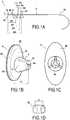
- the implantable device 1 shown in FIG. Figure 1Ais intended for the treatment of hiatal hernia. It comprises an elongate element of approximation 2, which comprises along its length a first support piece 3, fixed and ending one of the ends 2a of said elongate member 2, and four locking pieces 4,5,6,7 successive.
- the first 4, second 5, third 6 and fourth 7 locking piecesare respectively at distances D1, D2, D3, D4 of the contact face 3a of said first support piece 3, that is to say which is intended to come to apply against one of the anatomical structures to be brought together.
- D1, D2, D3, D4are respectively 10 mm, 15 mm, 20 mm and 25 mm.
- Blocking parts 4,5,6,7respectively a height h4, h5, h6, h7 of the same order, in this specific example of the order of 5 mm.
- the locking pieces 4,5,6,7have a generally frustoconical shape whose smallest base is oriented on said elongated element 2 in a direction opposite to the first support piece 3.
- the first support piece 3 and the blocking pieces 4,5,6,7are fixed along the length of said elongated element 2 by any means known from the state of the art, for example by gluing.
- the device 1comprises a second support piece 8 having an orifice 8a allowing the passage of said elongated member 2 and a contact face 8b intended to be applied against the other anatomical structure to be brought together.
- the contact faces 3a and 8b of the first 3 and second 8 support piecesare substantially planar and have a general shape of ellipse or circular. They are both able to develop a cicatricial fibrosis.
- the second support piececonsists of a main body 80 and a textile piece 81, which is pressed on the inner face of the main body 80 and which acts as contact face 8b.
- the main body 80which is covered with the textile piece capable of allowing the development of cicatricial fibrosis.
- the first support piece 3also formed of a main body and a textile piece plated on the inner face of said main body and forming the contact face 3a of said first support piece 3.
- the textile part 81is for example a nonwoven, preferably polyethylene terephthalate, said piece making from 30 to 500 g / m 2 and having a thickness of the order of 0.05 to 0.70 mm.
- a textile piece 80allows the development of fibrosis during contact with the anatomical structure. This fibrosis develops in the thickness of said textile piece, which allows an anchoring of said piece, and therefore of the support piece 8 which is integral therewith, on said anatomical structure.
- the first support piece 30consists of a rigid or semi-rigid main body 31 and a flexible piece which projects radially around the perimeter of the main body 31, said flexible piece being able to pass from an insertion position in which it is folded on itself to an implantation position in which it is deployed to come to be applied to one of the anatomical structures to be brought closer together .
- the flexible piece 32has an annular configuration being secured to the inner face 31a of the main body 31, itself circular configuration, by its central edge 32a.
- the contact face of the support piece 30is constituted by the flexible piece 32 and by the inner surface portion 31a of the main body 31, which is not covered by the flexible piece 32.
- the development of cicatricial fibrosisintervenes only on a part of the contact face, namely that which corresponds to the flexible piece 32.
- the flexible piece 33is of circular configuration, with just a through hole 34 for the elongate member.
- the contact face 33suitable for the development of cicatricial fibrosis, is formed in its entirety by the flexible piece 33.
- the flexible piece which may be a nonwoven as in the aforementioned embodimentis preferably secured to the main body 30 by any known technique, including welding, ultrasound or gluing.
- the flexible part 33is in the form of a part which, initially, is independent of the main body 31, being slidably mounted along the elongated element 2 by the practitioner during implantation.
- the fastening of the flexible part 33 to the main body 31is, in a natural way, by the compression effect obtained during the approximation of the anatomical structures followed by the blocking in the tightened position of the two support pieces by the action of the blocking part.
- the first support piece 3has the general shape of a flat plate.
- the second support piece 8comprises a hollow frustoconical piece 9 extending from its outer face 8c.
- the frustoconical piece 9has cutouts 10 forming lateral fins 11 and having a central recess 9a which extends the passage opening 8a.
- the outlet diameter of the recess 9a of said frustoconical piece 9is smaller than the size of the locking pieces 4,5,6,7.
- the elongate element 2has a rigid and curved end 2b opposite said first support piece 3.
- the device 1also comprises a protector in the form of a strip 12 in an elastic and implantable material, of preferably based on silicone, having a width l1 of the order of the height h1 of said frustoconical piece 9, preferably of the order of the height h1 added to the height h4, h5, h6, h7 of one of blocking parts 4,5,6,7.
- Said band 12is arranged in operation on the frustoconical piece 9 so as to cover not only the lateral cutouts 10, but also the locking piece 4,5,6,7 to protect the anatomical structures close to any perforations due to the thinned end, generally in the shape of a tip, of the locking piece 4,5,6,7.
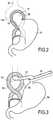
- the figure 2is a schematic representation of a hiatal hernia 13 highlighting the rise by the esophageal hiatus 13 of a portion 14a of the stomach 14 following a distention between the pillars 15,16 of the diaphragm.
- the device 1is preferably implanted by laparoscopy. First, the base of the esophagus 17 is removed by means of a lake 18 kept under tension and being in the form of a bead to disengage the abutments 15, 16 ( figure 3 ). Then the elongated element 2 is introduced through the pillars 15, 16, substantially at their centers, from its curved end 2b serving as means for introducing said elongate element 2 ( figure 4 ).
- the elongated element 2is thus introduced until the contact face 3a of the first support part 3 comes into abutment and abuts against the outer surface of the pillar 16 ( figure 5 ). Then the practitioner puts in tension the elongated element 2 by means of a traction member 19 passed through the inner conduit of a pusher 20 and attached to its curved end 2b.
- the second support piece 8can be easily threaded from the curved and rigid end 2b and then pushed through said inner conduit by means of a piston actuated by the practitioner.
- the practitionerthen has the second support piece 8 against the second pillar 15 by actuating both the organ of pulling 19 tensioning said elongated member 2 and the piston to force the second piece 8 on each blocking piece (7 to 4) to the locking piece 4 predetermined by the practitioner according to the degree of distension of the pillars 15 , 16 ( figure 6 ).
- the second support piece 8is inserted so that its contact face 8b bears and abuts against the outer surface of the second pillar 15.
- the fins 11 of the frustoconical piece 9deform radially for its passage. In the illustrated example, it is the fourth locking piece 4 which comes into rear abutment against the second support piece 8.
- the practitioneradjusts the bringing together of the two pillars 15 , 16 by means of the locking pieces which it forces one by one through said second support piece 8.
- the second piece 8was forced over the four locking pieces 4,5,6,7.
- the space delimited between said support pieces 3.8thus has at least one dimension D 1 less than 10 mm capable of receiving and gripping the two pillars 15, 16 of the diaphragm.
- the practitionercuts the elongate element 2 flush with the fourth locking piece 4 abuts against the second support piece 8 and removes the slender member portion 2 cut and the pusher 20 and the lake 18.
- the band 12is pre-positioned on the frustoconical piece 9 before implantation.
- the elastic band 12prevents during the passage of force blocking parts 4,5,6,7, causing the deformation of the fins, that the elongated element 2 passes through one of the side cuts and does not come shear the pillars 15,16 and / or interfere with the handling of the device 1 by the practitioner.
- the device 1 thus implantedis perfectly maintained in tension by said locking piece 4, which also maintains the contact faces 3a, 8b against the fibrous abutments 15, 16.
- the device 1has no part capable of shearing the outer surface of the pillars 15,16.
- the pillars 15, 16are kept close together durably, in particular because of the development of cicatricial fibrosis in the contact faces of the two support pieces, a development which prevents any slippage of the support pieces with respect to the anatomical structures and consequently all possible effect of shearing said anatomical structures by the elongate element which passes through them from side to side.
- the procedure which has been presented above for the device 1must be slightly completed for the variant embodiments in which the support part is composed of a main body and a flexible part which projects radially according to all or part of the circumference of said main body, as illustrated in Figures 14 and 15 .
- the devicein the case of a laparoscopic intervention, the device is introduced into a trocar whose inside diameter is slightly greater than the diameter of the main body, the flexible part being in the folded-back position on itself inside said trocar.
- the practitionermust also slide along the elongate element said flexible piece so that it comes into contact first with the face inside the support piece and then with the outer surface of the corresponding anatomical structure. Admittedly, the procedure is a little more complex when the flexible part is independent of the main body of the support piece but this disadvantage is offset by the advantage for the practitioner of power, before implantation, choose the dimension desired for the flexible part, either among different pieces of different dimensions, or by itself performing the desired dimensioning by cutting a large part.
- the flexible pieceWhen the flexible piece is independent of the main body of the support piece, it has only one hole for the sliding passage of the elongate element 2. In this case, the development of cicatricial fibrosis is also propagated in this case. passage hole, which also ensures the locking in position of the elongated element 2 relative to the flexible part 3, definitely eliminates the risk of shearing anatomical structures by said elongate element 2.
- the outer face 32b, 33b of the flexible piece 32,33namely that which does not come into contact with the anatomical structure is, at least in its radial extension beyond the main body 31, able to prevent the development of the cicatricial fibrosis, this in order to prevent there may be anarchic development of fibrosis in the case where an anatomical structure other than that whose approach is sought would come into contact with this outer face 32b, 33b.
- the outer face 32b, 33bmay be coated with a silicone coating or impregnation.
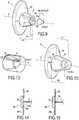
- the frustoconical piece 9 'shown in FIGS. figures 10 and 11is a variant of the frustoconical piece 9 described above. Only the elements of the frustoconical piece 9 'which differs from the part 9 are renumbered.
- the frustoconical piece 9 'has an internal shoulder 9'a having a depth h1' in its end portion 9b forming a housing adapted to receive a portion of the height h4, h5, h6, h7 of one of the locking pieces 4,5,6,7.
- the width l1 'of the band 12'is of the order of the height h1 of the frustoconical piece 9 'plus the height h4, h5, h6, h7 minus the depth h1' of the internal shoulder 9a so in operation (as represented in part by the figure 10 ), the band 12 'covers both the lateral cutouts 10 and the locking piece portion emerging from the shoulder 9a.
- the elongated element 2is not likely to shear neighboring anatomical structures passing through one of the cuts, and the thinned or sharp end of the blocking piece is not likely to perforate said structures.
- the main bodies 30, 80 of the first 3 and second 8 supporting parts, including the frustoconical parts 9, 9 'and the locking pieces 4,5, 6, 7are molded, preferably in a polymer.
- a polymerselected from the following polymers: PEEK (polyetheretherketone), POM (polyoxymethylene), PET (polyethylene terephthalate), PP (polypropylene), PE (polyethylene).
- the protector 12 "shown in figure 13is a variant of the protector or strip 12 'shown in FIG. figure 10 . Only the elements of the frustoconical piece 9 'that differs from the piece 9 are renumbered to the figure 13 .
- This 12 "protectoris molded at the same time as the second support piece 8 and the first frustoconical piece 9 ', preferably in a polymer chosen from the following polymers: PEEK (polyetheretherketone), POM (polyoxymethylene), PET (polyethylene terephthalate), PP (polypropylene) , PE (polyethylene).
- the protector 12 "being in this case rigid, is in the form of a cylinder extending from the face 8c of the second support piece 8.
- the protector 12"covers the lateral cutouts 10 of the hollow frustoconical piece 9 'without coming into direct contact with said frustoconical piece 9' and therefore its fins 11 so as to provide a free space, delimited between said frustoconical piece 9 'and said protector 12', wherein said fins 11 can deform radially at the force passage of the locking piece 4,5,6,7.
- the device 1 'shown in FIG. figure 11differs from the device 1 in that it comprises two elongate elements 21,22.
- the first support piece 23has a flat contact face 23a sufficient to be fixed in two different fastening zones 23b, 23c at the ends 21a, 22a of the first 21 and second 22 elements.
- Each elongated element 21, 22has four locking pieces, preferably arranged as described above.
- the second support piece 24, at the figure 12comprises a first 24a and a second 24b passage orifices to be slidably mounted at the same time respectively on the first 21 and the second 22 elongate elements.
- Opposite the first support piece 23, the free ends 21b, 22b of the elements 21, 22are rigid and curved.
- the second support piece 24comprises two frustoconical parts 25,26 projecting from its outer face 24c identical to the frustoconical piece 9 of the device 1 and each having in operation a band of the type of the strip 12.
- the practitionersuccessively passes the first element 21 and the second element 22 through the pillars of the diaphragm until the first support piece 23 abuts against a first pillar. Then he puts the second support piece 24 on the first 21 and second 22 elongate elements with the first 24a and second 24b through holes. Each of the locking pieces disposed along the length of the first 21 and second 22 elements is forced through the first 24a and second 24b through holes.
- the practitionerblocks the second support piece 24 with two locking pieces arranged substantially at a distance of the same order from the first support 23.
- the second elongate element 22, like the first elongate element 21,does not shear the pillars and reinforces the clamping pressure exerted by the device 1 'and in particular the first 23 and second 24 support pieces.
- the device 1'allows the use of support pieces 23,24 having contact faces greater than those of the parts 3,8 of the device 1, and to better balance the distribution of the tensions exerted by the first 21 and second 22 elongated elements between said parts 23,24.
- the frustoconical parts 25,26each comprise a protector in the form of a tube in an adherent elastic material equivalent to the protector 12 of the device 1.
- the first and the second support membersconsist of a main body and an insert which have the required properties on the development of cicatricial fibrosis.
- the first and second support piecescan be in one piece, the contact face having the properties allowing the development of fibrosis that can result from the structure itself of the support piece or appropriate treatment , in particular locally conferring on said support piece adequate porosity, with open pores allowing the development of said fibrosis.
Landscapes
- Health & Medical Sciences (AREA)
- Life Sciences & Earth Sciences (AREA)
- Surgery (AREA)
- Heart & Thoracic Surgery (AREA)
- Engineering & Computer Science (AREA)
- Biomedical Technology (AREA)
- Nuclear Medicine, Radiotherapy & Molecular Imaging (AREA)
- Medical Informatics (AREA)
- Molecular Biology (AREA)
- Animal Behavior & Ethology (AREA)
- General Health & Medical Sciences (AREA)
- Public Health (AREA)
- Veterinary Medicine (AREA)
- Rheumatology (AREA)
- Prostheses (AREA)
Description
Translated fromFrenchLa présente invention concerne un dispositif implantable destiné à réaliser le rapprochement de structures anatomiques fragiles, notamment mais non exclusivement le rapprochement des piliers du diaphragme dans le traitement de la hernie hiatale.The present invention relates to an implantable device intended to achieve the approximation of fragile anatomical structures, including but not exclusively the approximation of the pillars of the diaphragm in the treatment of hiatal hernia.
A l'état normal, l'orifice hiatal est traversé par le segment distal de l'oesophage accompagné des nerfs vague antérieur et postérieur. La jonction entre l'estomac et l'oesophage (cardia) est normalement située en dessous du diaphragme. Le muscle diaphragmatique sépare la cavité abdominale et la cavité thoracique. Il présente trois orifices qui permettent le passage de la veine cave, de l'aorte et de l'oesophage. L'orifice de passage de l'oesophage est dénommé orifice hiatal. Il est formé essentiellement par le pilier diaphragmatique droit, avec une contribution plus faible du pilier gauche. Le pilier droit prend son origine au niveau du ligament vertébral longitudinal antérieur qui couvre les vertèbres lombaires.In the normal state, the hiatal opening is crossed by the distal segment of the esophagus accompanied by anterior and posterior vagus nerves. The junction between the stomach and the esophagus (cardia) is normally located below the diaphragm. The diaphragmatic muscle separates the abdominal cavity and the thoracic cavity. It has three orifices that allow the passage of the vena cava, the aorta and the esophagus. The passage opening of the esophagus is called the hiatal orifice. It is formed essentially by the right diaphragmatic pillar, with a smaller contribution from the left pillar. The right pillar originates from the anterior longitudinal vertebral ligament that covers the lumbar vertebrae.
Une hernie hiatale est provoquée par une altération de l'anatomie de l'orifice hiatal. Des structures anatomiques normalement confinées dans la cavité abdominale passent alors au travers dudit orifice déformé et se retrouvent en position intra-thoracique.A hiatal hernia is caused by an alteration of the anatomy of the hiatal orifice. Anatomical structures normally confined in the abdominal cavity then pass through said deformed orifice and are found in the intrathoracic position.
Quatre types de hernie hiatale peuvent alors survenir, répertoriées selon leur gravité croissante :
- le premier type est une hernie hiatale par glissement. L'orifice hiatal est élargi et la membrane phréno-oesophagienne distendue ce qui permet l'ascension de la jonction gastro-oesophagienne au dessus du diaphragme. La plupart des hernies de ce type sont asymptomatiques. Elles peuvent cependant entraîner l'apparition d'une maladie de reflux gastro-oesophagien par la perte de la compétence du mécanisme sphinctérien oesophagien inférieur.
- le second type est une hernie para-oesophagienne. La jonction gastro-oesophagienne demeure en place, mais la partie supérieure de l'estomac (fundus) migre vers le thorax au travers d'une zone de faiblesse de la membrane phréno-oesophagienne. Ce type de hernie peut entraîner des complications mécaniques ou vasculaires au niveau du bas oesophage ou de l'estomac hernié ;
- le troisième type est une hernie mixte. Elle combine des éléments des deux premiers types. Dans certains cas, la totalité de l'estomac peut se retrouver en position sus-diaphragmatique ;
- le quatrième type est caractérisé par un élargissement important de l'orifice diaphragmatique, permettant la herniation, non seulement de l'estomac, mais également d'autres structures abdominales (colon, rate).
- the first type is a sliding hiatal hernia. The hiatal opening is enlarged and the phrenoesophageal membrane distended allowing ascension of the gastro-oesophageal junction above the diaphragm. Most hernias of this type are asymptomatic. However, they can lead to the development of gastroesophageal reflux disease by losing the competence of the lower esophageal sphincter mechanism.
- the second type is a para-oesophageal hernia. The gastroesophageal junction remains in place, but the upper part of the stomach (fundus) migrates to the thorax through a zone of weakness of the phrenoesophageal membrane. This type of hernia can lead to mechanical or vascular complications in the lower esophagus or herniated stomach;
- the third type is a mixed hernia. It combines elements of the first two types. In some cases, the entire stomach may be in an over-diaphragmatic position;
- the fourth type is characterized by a large enlargement of the diaphragmatic orifice, allowing herniation, not only of the stomach, but also of other abdominal structures (colon, spleen).
Le traitement d'une hernie hiatale, quel que soit le type de hernie, comporte la réduction de la hernie, c'est-à-dire le repositionnement des viscères herniés en dessous du diaphragme, et la plastie de l'orifice hiatal élargi.The treatment of a hiatal hernia, whatever the type of hernia, involves the reduction of the hernia, that is to say the repositioning of the herniated viscera below the diaphragm, and the plasty of the enlarged hiatal opening.
La plastie de l'orifice hiatal consiste en la recalibration de l'orifice hiatal autour de l'oesophage, sans comprimer mécaniquement l'oesophage tout en assurant une fermeture satisfaisante qui doit empêcher une récidive de la hernie. Cette réparation est appliquée sur une structure musculaire (piliers du diaphragme) qui n'a pas la résistance d'une structure aponévrotique et qui est sollicitée par des variations de pressions intra-abdominales (positives) et thoraciques (négatives).The plasty of the hiatal opening consists of the recalibration of the hiatal opening around the esophagus, without mechanically compressing the esophagus while ensuring a satisfactory closure which must prevent recurrence of the hernia. This repair is applied to a muscular structure (pillars of the diaphragm) that does not have the resistance of a fascial structure and is solicited by intra-abdominal (positive) and thoracic (negative) pressure variations.
La localisation de l'orifice hiatal (postérieure) accroît la difficulté du geste technique.The location of the hiatal (posterior) orifice increases the difficulty of the technical gesture.
Ce dispositif comprend un élément longiligne, une première pièce d'appui disposée sur la longueur dudit élément qui peut être rigide puisque éventuellement dans un métal tel que l'acier inoxydable, une seconde pièce d'appui, un plug et des pièces de blocage.This device comprises an elongated element, a first support part disposed along the length of said element which can be rigid since possibly in a metal such as stainless steel, a second support piece, a plug and locking pieces.
Le plug peut comprendre des composants cellulaires ou chimiques qui facilitent la fibrose.The plug can include cellular or chemical components that facilitate fibrosis.
Une première technique de plastie des hernies hiatales consiste à suturer avec des fils de suture non résorbables les piliers du diaphragme, en avant et/ou en arrière de l'oesophage. Des languettes, généralement en PTFE, peuvent être intercalées entre le fil de suture et les piliers du diaphragme pour éviter de cisailler les structures musculaires, cette technique de suture est alors appelée suture appuyée. Malgré cette précaution, on observe un effet de cisaillement des piliers gauche et droit, particulièrement avec la technique de suture simple. Cette première technique réalisée par laparoscopie rapporte des taux de récidive jusqu'à 42 % supérieurs aux taux de récidive observés dans la chirurgie conventionnelle, c'est-à-dire par laparotomie. Il n'existe pas d'étude randomisée comparant la suture simple et la suture appuyée. La différence des taux de récidive entre la chirurgie ouverte et la chirurgie laparoscopique laisse suspecter l'existence de difficultés techniques propres à la chirurgie laparoscopique.A first technique of plasty of hiatal hernias is to suture with nonabsorbable sutures the pillars of the diaphragm, forward and / or back of the esophagus. Tabs, usually made of PTFE, can be inserted between the suture and the diaphragm pillars to avoid shearing the muscle structures, this suture technique is then called suture supported. Despite this precaution, we observe a shear effect of the pillars left and right, especially with the simple suture technique. This first technique performed by laparoscopy reports recurrence rates up to 42% higher than the recurrence rates observed in conventional surgery, that is to say by laparotomy. There is no randomized study comparing simple suture and supported suture. The difference in recurrence rates between open surgery and laparoscopic surgery suggests that there are technical difficulties with laparoscopic surgery.
Une seconde technique consiste à renforcer la suture des piliers en la recouvrant d'une prothèse qui entoure partiellement ou totalement l'oesophage. Pour être efficace, la prothèse est invariablement proche de la paroi de l'oesophage. Une étude réalisée sur une durée courte -6 mois- démontre un taux de récidive de 9% après renforcement au moyen d'une prothèse contre 24% pour la suture simple. Ces résultats favorables doivent être contre-balancés par la description de complications sévères liées à l'utilisation du matériel prothétique. Un contact direct entre la prothèse et la paroi de l'oesophage peut provoquer soit une réaction inflammatoire fibreuse qui entraîne une sténose de l'oesophage, soit une érosion progressive de la paroi oesophagienne avec pénétration de la prothèse dans la lumière de l'oesophage. Ces complications nécessitent une reprise chirurgicale pouvant aller jusqu'à la résection de l'oesophage. La probabilité d'observer ces complications est majorée par le fait que le contact prothèse-oesophage est dynamique, entre les mouvements respiratoires du diaphragme et les mouvements péristaltiques de l'oesophage, non synchronisés.A second technique involves strengthening the suture of the pillars by covering it with a prosthesis that partially or totally surrounds the esophagus. To be effective, the prosthesis is invariably close to the wall of the esophagus. A study carried out over a short period of 6 months demonstrates a recurrence rate of 9% after reinforcement with a prosthesis compared to 24% for simple suture. These favorable results must be counterbalanced by the description of severe complications related to the use of prosthetic equipment. Direct contact between the prosthesis and the wall of the esophagus can cause either a fibrous inflammatory reaction that causes stenosis of the esophagus, or progressive erosion of the esophageal wall with penetration of the prosthesis into the lumen of the esophagus. These complications require surgical revision up to resection of the esophagus. The probability of observing these complications is increased by the fact that prosthesis-esophageal contact is dynamic, between the respiratory movements of the diaphragm and the peristaltic movements of the esophagus, which are not synchronized.
Une troisième technique consiste à disposer une prothèse sur l'orifice hiatal sans tension, c'est-à-dire sans suture préalable des piliers. Aucun suivi à long terme n'a été rapporté à ce jour sur cette dernière technique.A third technique is to have a prosthesis on the hiatal orifice without tension, that is to say without prior suture of the pillars. No long-term follow-up has been reported to date on this latter technique.
De nombreuses études ont démontré que la récidive de la hernie hiatale est la cause principale d'échec du traitement chirurgical du reflux gastro-oesophagien et de la hernie hiatale. Elle est à l'origine de la majorité des reprises chirurgicales. La récidive est provoquée par la rupture, la distension ou une malfaçon de la plastie crurale.Numerous studies have shown that recurrence of hiatal hernia is the main cause of failure of surgical treatment of gastroesophageal reflux and hiatus hernia. She is at the origin of the majority of surgical revisions. Recurrence is caused by rupture, distention or malfunction of the crural plasty.
Trois facteurs doivent être pris en considération lors du traitement d'une hernie hiatale :
- la longueur de l'oesophage. Elle doit être suffisante pour permettre le repositionnement sans tension de la jonction gastro-oesophagienne sous le diaphragme ;
- la qualité des piliers du diaphragme. En cas de hernie volumineuse, les piliers peuvent être très écartés et réduits à deux fines bandes musculaires fragiles ;
- la qualité de la plastie de l'orifice hiatal. 90 à 95% des hernies observées dans la maladie de reflux gastro-oesophagien sont des hernies du premier type décrit ci-dessus et donc de petite taille, avec conservation d'une musculature satisfaisante. La situation anatomique de l'orifice hiatal peut rendre difficile un geste de suture laparoscopique dont la qualité dépend significativement de l'expérience de l'opérateur.
- the length of the esophagus. It must be sufficient to allow tension-free repositioning of the gastroesophageal junction under the diaphragm;
- the quality of the pillars of the diaphragm. In case of bulging hernia, the pillars can be widely separated and reduced to two thin fragile muscle bands;
- the quality of a plasty of a hiatal opening. 90 to 95% of hernias observed in gastro-oesophageal reflux disease are hernias of the first type described above and therefore of small size, with preservation of a satisfactory musculature. The anatomical situation of the hiatal orifice can make difficult a laparoscopic suture gesture whose quality depends significantly on the experience of the operator.
La technique qui s'applique dans le cadre de la présente divulgation, s'agissant du traitement de la hernie hiatale, s'apparente à la première technique de plastie précitée en ce qu'elle cherche à rapprocher les piliers du diaphragme en avant et/ou en arrière de l'oesophage. Selon la présente divulgation, il ne s'agit pas de suturer les piliers du diaphragme avec des fils de suture classiques mais de mettre en oeuvre un dispositif particulièrement adapté au rapprochement desdits piliers.The technique that applies in the context of the present disclosure, with regard to the treatment of hiatal hernia, is similar to the first technique of the aforementioned plasty in that it seeks to bring the pillars of the diaphragm forward and / or or behind the esophagus. According to the present disclosure, it is not a question of suturing the pillars of the diaphragm with conventional sutures, but of implementing a device that is particularly suitable for bringing said abutments closer together.
Un tel dispositif n'est pas limité au traitement de la hernie hiatale mais peut s'appliquer au rapprochement de structures anatomiques fragiles, que ce soit des structures musculaires telles que la paroi abdominale, les piliers du diaphragme, le coeur, l'estomac ou l'utérus ou des structures parenchymateuses telles que les reins, le foie et les poumons.Such a device is not limited to the treatment of the hiatal hernia but can be applied to the approximation of fragile anatomical structures, be it muscle structures such as the abdominal wall, the pillars of the diaphragm, the heart, the stomach or the uterus or parenchymal structures such as the kidneys, liver and lungs.
Ledit dispositif comprend un élément longiligne, destiné à traverser de part en part les structures anatomiques à rapprocher, ledit élément longiligne comportant sur sa longueur une première pièce d'appui qui comporte une face de contact destinée à s'appliquer sur l'une des structures anatomiques à rapprocher et au moins une pièce de blocage qui est située à une distance donnée D de la face de contact de ladite première pièce d'appui. Le dispositif comprend également une seconde pièce d'appui qui comporte une face de contact destinée à s'appliquer sur une autre des structures anatomiques à rapprocher, ladite seconde pièce d'appui étant apte à coulisser sur la longueur de l'élément longiligne et étant conformée en sorte que, lors de l'implantation, la pièce de blocage est forcée à travers la seconde pièce d'appui et vient en butée arrière contre celle-ci, les faces de contact des première et seconde pièces d'appui étant tournées l'une vers l'autre et délimitant un espace apte à recevoir et enserrer les structures anatomiques à rapprocher. Enfin, chaque face de contact est, au moins en partie, apte à développer une fibrose cicatricielle.Said device comprises an elongated element, intended to pass right through the anatomical structures to be brought together, said elongate element comprising along its length a first support piece which has a contact face intended to be applied to one of the structures anatomical devices to be brought together and at least one locking piece which is situated at a given distance D from the face contacting said first support piece. The device also comprises a second support piece which has a contact face intended to be applied to another of the anatomical structures to be brought together, said second support piece being able to slide along the length of the elongate element and being shaped so that, during implantation, the locking piece is forced through the second bearing piece and abuts against it, the contact faces of the first and second bearing parts being rotated; one towards the other and delimiting a space able to receive and enclose the anatomical structures to be brought closer together. Finally, each contact face is, at least in part, able to develop a cicatricial fibrosis.
Ainsi, selon les dispositions particulières de la présente divulgation, lorsque les structures anatomiques sont rapprochées, étant enserrées entre les faces de contact des deux pièces d'appui, et que la fibrose cicatricielle se développe dans lesdites faces, on obtient un blocage définitif en position de l'ensemble constitué par les deux pièces d'appui et l'élément longiligne de sorte que ledit élément longiligne n'a plus la possibilité de se déplacer perpendiculairement aux structures anatomiques et qu'il n'y a donc plus de risques de cisaillement desdites structures.Thus, according to the particular provisions of the present disclosure, when the anatomical structures are close together, being sandwiched between the contact faces of the two support pieces, and the cicatricial fibrosis develops in said faces, a definitive locking in position is obtained. of the assembly constituted by the two supporting parts and the elongate element so that said elongate element no longer has the ability to move perpendicular to the anatomical structures and that there is therefore no risk of shearing said structures.
Etant donné qu'il s'agit de rapprocher des structures anatomiques fragiles, chaque face de contact de la pièce d'appui doit présenter, selon l'interprétation qu'il convient de faire de ce terme selon la présente divulgation, une surface suffisante pour éviter les risques de déformation voire de pénétration de la pièce d'appui dans la structure anatomique contre laquelle elle vient s'appliquer lors de l'implantation.Since it is a question of bringing closer to fragile anatomical structures, each contact face of the support piece must have, according to the appropriate interpretation of this term according to the present disclosure, a sufficient surface to avoid the risk of deformation or penetration of the support piece in the anatomical structure against which it comes to apply during implantation.
Ainsi la terminaison en T du dispositif décrit dans le document
A titre indicatif, chaque face de contact a une surface qui fait au moins 40 mm2. Il peut s'agir notamment d'une face de configuration elliptique ou circulaire, dans ce dernier cas ayant un diamètre de l'ordre de 8 mm.As an indication, each contact face has a surface that is at least 40 mm2 . It may be in particular a face of elliptical or circular configuration, in the latter case having a diameter of about 8 mm.
Contrairement aux techniques de sutures simples et appuyées encerclant en partie au moins deux structures anatomiques, telles que les piliers gauche et droit, l'élément longiligne traverse lesdites structures anatomiques, lesquelles sont maintenues entre les faces de contact des première et seconde pièces d'appui. Il n'y a donc pas de fil de suture venant directement en contact avec la surface extérieure desdites structures anatomiques, ce qui élimine les risques de cisaillement de ces dernières qui sont des structures fragiles, particulièrement en ce qui concerne les piliers du diaphragme qui sont des muscles « tendres ». Lesdites structures anatomiques, par exemple les piliers, sont enserrées entre les pièces d'appui bloquées et distantes d'une distance déterminée, qui est fonction de la distance entre la face de contact de la première pièce d'appui et la pièce de blocage assurant le blocage de la seconde pièce d'appui, de sorte que le praticien connaît précisément la distance selon laquelle il a rapproché lesdites structures anatomiques, ce qui augmente ainsi la précision de la technique opératoire.In contrast to simple and supported suture techniques partially encircling at least two anatomical structures, such as left and right abutments, the elongate element passes through said anatomical structures, which are held between the contact faces of the first and second support pieces. . There is therefore no suture directly in contact with the outer surface of said anatomical structures, which eliminates the risk of shearing the latter which are fragile structures, particularly with regard to the pillars of the diaphragm which are "soft" muscles. Said anatomical structures, for example the pillars, are sandwiched between the support pieces locked and distant by a determined distance, which is a function of the distance between the contact face of the first support piece and the locking piece ensuring the blocking of the second support piece, so that the practitioner knows precisely the distance by which he has brought said anatomical structures, thereby increasing the accuracy of the surgical technique.
Dans le cas du traitement de la hernie hiatale, le dispositif une fois implanté ne comporte pas de bords extérieurs susceptibles d'entrer en contact avec la paroi oesophagienne. Le dispositif est facile à mettre en place contrairement aux prothèses et sutures utilisés dans l'état de la technique ce qui diminue les risques post-opératoires de récidive. De plus, ledit dispositif étant peu encombrant peut être implanté facilement par laparoscopie. Les piliers gauche et droit viennent en appui contre les faces de contact des première et seconde pièces d'appui et sont retenus définitivement dans leur position resserrée entre ces dernières tout particulièrement après le développement de la fibrose cicatricielle. Il est bien sûr possible d'implanter le dispositif selon la présente divulgation par laparotomie.In the case of treatment of the hiatal hernia, the device once implanted has no external edges likely to come into contact with the esophageal wall. The device is easy to implement unlike the prostheses and sutures used in the state of the art which reduces the post-operative risk of recurrence. In addition, said device being compact can be easily implanted by laparoscopy. The left and right pillars abut against the contact faces of the first and second support pieces and are permanently retained in their narrowed position between the latter especially after the development of cicatricial fibrosis. It is of course possible to implant the device according to the present disclosure by laparotomy.
La première pièce d'appui et la ou les pièces de blocage sont fixées ou fixables sur la longueur dudit élément longiligne par n'importe quels moyens mécaniques ou chimiques connus de l'état de la technique : clipsage, collage, soudures ultrasons ou haute fréquences..., ou encore en réalisant un noeud sur lui-même dudit élément longiligne faisant office de pièce de blocage ou de butée arrière pour ladite première pièce d'appui.The first support piece and the one or more locking pieces are fixed or fixable along the length of said elongate element by any mechanical or chemical means known from the state of the art: clipping, gluing, ultrasonic or high-frequency welding ..., or again by making a knot on itself of said elongate member acting as a locking piece or rear stop for said first support piece.
Chaque première pièce d'appui est constituée d'un corps principal rigide ou semi-rigide, et d'une pièce souple qui se projette radialement selon tout ou partie du pourtour du corps principal et qui est apte à passer d'une position d'introduction dans laquelle elle est repliée sur elle-même à une position d'implantation dans laquelle est déployée pour venir s'appliquer sur l'une des structures anatomiques à rapprocher. La face de la pièce souple qui, lors de l'implantation, est destinée à être appliquée sur la structure anatomique fait bien sûr office de face de contact selon la présente invention, étant notamment apte à développer la fibrose cicatricielle.Each first support piece is constituted by a rigid or semi-rigid main body, and a flexible piece which projects radially along all or part of the periphery of the main body and which is able to pass from a position of introduction in which it is folded on itself to an implantation position in which is deployed to come to apply to one of the anatomical structures to be brought together. The face of the flexible part which, during implantation, is intended to be applied to the anatomical structure is of course used as a contact face according to the present invention, being particularly suitable for developing cicatricial fibrosis.
Ainsi, c'est la face du corps principal qui est en regard de la structure anatomique qui est à prendre en considération en ce qui concerne le serrage desdites structures anatomiques lors du rapprochement de celles-ci. Par contre, lorsque la fibrose cicatricielle s'est développée, c'est l'ensemble de la surface incluant l'extension radiale de la pièce souple au-delà du corps principal qui est à prendre en considération dans le blocage à long terme des deux structures anatomiques en position resserrée. Cette variante de réalisation est particulièrement adaptée pour les implantations qui interviennent par voie laparoscopique, puisque dans ce cas on peut utiliser pour l'introduction du dispositif un trocart de faible diamètre, correspondant sensiblement à celui du corps principal des deux pièces d'appui.Thus, it is the face of the main body which is opposite the anatomical structure which is to be considered with regard to the tightening of said anatomical structures when the latter are brought together. On the other hand, when the cicatricial fibrosis has developed, it is the whole of the surface including the radial extension of the flexible part beyond the main body which is to be taken into account in the long-term blockage of the two anatomical structures in a constricted position. This variant embodiment is particularly suitable for laparoscopic implantations, since in this case it is possible to use a small diameter trocar for the introduction of the device, corresponding substantially to that of the main body of the two supporting parts.
De préférence, la pièce souple, au moins dans son extension radiale au-delà du corps principal, comporte sur sa face opposée à la face de contact des moyens aptes à empêcher le développement de la fibrose cicatricielle. Il peut notamment s'agir d'une enduction ou d'une imprégnation de silicone. Le but visé par cette disposition particulière est d'éviter qu'il puisse y avoir un développement anarchique de fibrose dû à la présence de cette pièce souple s'il arrivait que celle-ci vienne en contact avec d'autres structures anatomiques que celles dont le rapprochement est recherché.Preferably, the flexible piece, at least in its radial extension beyond the main body, has on its face opposite the contact face means capable of preventing the development of cicatricial fibrosis. It may especially be a coating or a silicone impregnation. The purpose of this particular provision is to avoid that there may be an anarchic development of fibrosis due to the presence of this flexible piece if it came that it comes into contact with other anatomical structures than those of which the rapprochement is sought.
A titre d'exemple non exhaustif, le corps principal étant une pièce de configuration circulaire faisant de l'ordre de 8 mm de diamètre, l'extension radiale au-delà du corps principal présente un diamètre de 20mm.By way of non-exhaustive example, the main body being a piece of circular configuration making the order of 8 mm in diameter, the radial extension beyond the main body has a diameter of 20 mm.
A titre indicatif, chaque face de contact a une surface qui fait au moins 40 mm2. Il peut s'agir notamment d'une face de configuration elliptique ou circulaire, dans ce dernier cas ayant un diamètre de l'ordre de 8 mm.As an indication, each contact face has a surface that is at least 40 mm2 . It may be in particular a face of elliptical or circular configuration, in the latter case having a diameter of about 8 mm.
De préférence, chaque face de contact présente une surface qui reste supérieure à 40 mm2 pour éviter les risques de transpercement de la structure anatomique, et inférieure à 1300 mm2, pour éviter de générer des érosions entre la surface et la structure anatomique.Preferably, each contact face has a surface that remains greater than 40 mm2 to prevent the risk of piercing of the anatomical structure, and less than 1300 mm2 , to avoid generating erosions between the surface and the anatomical structure.
Selon une autre variante de réalisation, la face de contact de chaque pièce d'appui est constituée d'un matériau textile apte à permettre le développement d'une fibrose cicatricielle, notamment un non-tissé, par exemple de préférence en polyéthylènetéréphtalate (PET). Ce matériau textile peut occuper toute la surface de la pièce d'appui. Dans la variante particulière visée ci-dessus, il peut soit occuper uniquement la surface de l'extension radiale venant au-delà du corps principal soit occuper toute la surface de la face de contact, incluant le corps principal et l'extension radiale.According to another variant embodiment, the contact face of each support piece is made of a textile material capable of enabling the development of a cicatricial fibrosis, in particular a nonwoven, for example preferably polyethylene terephthalate (PET). . This textile material can occupy the entire surface of the support piece. In the particular variant referred to above, it can either occupy only the surface of the radial extension coming beyond the main body or occupy the entire surface of the contact face, including the main body and the radial extension.
Dans une variante de réalisation, la pièce d'appui comporte un corps principal et une pièce souple qui sont, avant implantation, indépendantes l'une de l'autre, ladite pièce souple étant apte à coulisser le long de l'élément longiligne pour venir contre le corps principal et former ainsi la face de contact de la pièce d'appui.In an alternative embodiment, the support piece comprises a main body and a flexible part which are, before implantation, independent of one another, said flexible part being able to slide along the elongated element to come against the main body and thus form the contact face of the support piece.
Dans une variante, la face de contact des première et seconde pièces d'appui est sensiblement plane, de préférence elle a une forme générale d'ellipse ou de cercle.In a variant, the contact face of the first and second support members is substantially flat, preferably it has a general shape of ellipse or circle.
Les faces de contact planes des première et seconde pièces d'appui sont plaquées contre les structures anatomiques, de sorte qu'elles ne peuvent cisailler ni endommager la structure musculaire fibreuse de ces dernières lorsqu'il s'agit de muscles, en particulier des piliers du diaphragme, pendant la période qui précède la fibrose cicatricielle.The planar contact faces of the first and second support pieces are pressed against the anatomical structures, so that they can not shear or damage the fibrous muscle structure of the latter when it comes to muscles, in particular pillars of the diaphragm, during the period preceding cicatricial fibrosis.
De préférence, la première pièce d'appui a une forme générale sensiblement plane.Preferably, the first support piece has a substantially flat overall shape.
Dans une variante, le dispositif comprend un second élément longiligne fixé sur la première pièce d'appui, et au moins une pièce de blocage située sur le second élément à une distance donnée D de la face de contact de la première pièce d'appui, la seconde pièce d'appui étant apte à coulisser sur la longueur dudit second élément longiligne en sorte que, lors de l'implantation, ladite pièce de blocage est forcée à travers ladite seconde pièce d'appui et vient en butée contre celle-ci.In a variant, the device comprises a second elongated element fixed on the first support piece, and at least one locking piece located on the second element at a given distance D of the contact face of the first support piece, the second bearing piece being slidable along the length of said second elongated member so that, during implantation, said locking piece is forced through said second bearing piece and abuts against it.
La seconde pièce d'appui est apte à coulisser à la fois sur le premier élément longiligne et sur le second élément longiligne.The second support piece is able to slide both on the first elongate element and on the second elongate element.
L'emploi d'un second élément longiligne permet de renforcer la pression exercée de part et d'autre desdites structures anatomiques respectivement par les première et seconde pièces d'appui.The use of a second elongate element makes it possible to reinforce the pressure exerted on either side of said anatomical structures respectively by the first and second support pieces.
Le second élément traverse également lesdites structures anatomiques de sorte qu'il ne peut cisailler leurs surfaces extérieures.The second element also passes through said anatomical structures so that it can not shear their outer surfaces.
Lorsque les structures anatomiques sont les deux piliers du diaphragme, le choix du nombre d'élément longiligne est fonction du renfort à apporter à la plastie du hiatus oesophagien et du type de hernie hiatale.When the anatomical structures are the two pillars of the diaphragm, the choice of the number of elongated element is a function of the reinforcement to be made to the plasty of the esophageal hiatus and the type of hiatal hernia.
Dans une variante, le premier, et éventuellement le second, élément longiligne comporte plusieurs pièces de blocage successives, de préférence ayant une hauteur du même ordre, à des distances prédéterminées D de la face de contact de ladite première pièce d'appui, de préférence la distance D est comprise dans l'intervalle [10 ; 25] mm.In a variant, the first, and possibly the second, elongated element comprises a plurality of successive locking pieces, preferably having a height of the same order, at predetermined distances D of the contact face of said first support piece, preferably the distance D is in the range [10; 25] mm.
Le premier, et éventuellement le second, élément longiligne comporte de préférence quatre pièces de blocage, la première étant à une distance D de préférence de l'ordre de 10 mm de la face de contact de la première pièce d'appui, les pièces de blocage suivantes étant espacées les unes des autres de préférence de l'ordre de 5 mm à compter de ladite première pièce de blocage. Les pièces de blocage sont autant de repère pour le praticien pour bloquer la seconde pièce d'appui et déterminer précisément la distance selon laquelle les structures anatomiques sont rapprochées ce qui n'était pas possible avec les sutures et orthèses mis en oeuvre dans l'état de la technique, particulièrement pour le traitement de la hernie hiatale.The first, and possibly the second, elongate member preferably comprises four locking pieces, the first being at a distance D preferably of the order of 10 mm from the contact face of the first support piece, the pieces of blocking being spaced apart from each other preferably of the order of 5 mm from said first blocking part. The blocking parts are also a reference for the practitioner to block the second support piece and precisely determine the distance by which the anatomical structures are close together which was not possible with the sutures and orthoses used in the state of the art, particularly for the treatment of hiatal hernia.
Les pièces de blocage disposées sur les premier et second éléments longilignes sont de préférence à égales distances de ladite première pièce d'appui de sorte que le praticien force deux pièces de blocage à la fois à travers la seconde pièce d'appui en sorte de former un espace délimité entre les première et seconde pièces d'appui ayant au moins une dimension sensiblement constante.The locking pieces disposed on the first and second elongate members are preferably at equal distances from said first support piece so that the practitioner forces two locking pieces at a time through the second support piece so as to form a space defined between the first and second support members having at least one substantially constant dimension.
La hauteur d'une pièce de blocage correspond à la longueur d'une portion de premier, ou de second, élément longiligne selon laquelle ladite pièce est fixée. De préférence, les pièces de blocage sont identiques et présentent une hauteur du même ordre.The height of a locking piece corresponds to the length of a portion of first or second elongate element in which said piece is fixed. Preferably, the locking pieces are identical and have a height of the same order.
La seconde pièce d'appui présente un premier orifice permettant le passage dudit premier élément longiligne, et éventuellement un second orifice permettant le passage dudit second élément longiligne.The second bearing piece has a first orifice allowing passage of said first elongate member, and optionally a second orifice allowing the passage of said second elongate member.
Le premier, et éventuellement le second, orifice permet à la seconde pièce d'appui de coulisser librement sur la longueur dudit premier, et éventuellement dudit second, élément longiligne.The first, and possibly the second, orifice allows the second support piece to slide freely along the length of said first, and possibly said second, elongate element.
Dans une variante, la seconde pièce d'appui comporte une première pièce tronconique creuse, et éventuellement une seconde pièce tronconique creuse, ayant des découpes formant des ailettes latérales et ayant un évidement central qui prolonge l'orifice de passage. Le diamètre de sortie de l'évidement de ladite pièce tronconique est inférieur à l'encombrement de la pièce de blocage, en sorte que le passage en force de la pièce de blocage à travers la seconde pièce d'appui est obtenu grâce à la déformation radiale des ailettes.In a variant, the second support piece comprises a first hollow frustoconical part, and possibly a second hollow frustoconical part, having cutouts forming lateral fins and having a central recess which extends the passage opening. The outlet diameter of the recess of said frustoconical piece is less than the size of the blocking piece, so that the force passage of the blocking piece through the second piece of support is obtained thanks to the deformation radial fins.
La première pièce tronconique creuse, et éventuellement la seconde pièce tronconique creuse, s'étend de préférence de la face extérieure de ladite seconde pièce d'appui de sorte que celle-ci conserve une face de contact sensiblement plane pour ne pas cisailler les structures anatomiques.The first hollow frustoconical piece, and possibly the second hollow frustoconical piece, preferably extends from the outer face of said second support piece so that it retains a substantially flat contact surface so as not to shear the anatomical structures. .
Dans une variante, la première, et éventuellement la seconde, pièce tronconique creuse comporte un épaulement interne dans sa portion d'extrémité formant un logement apte à recevoir tout ou partie de la hauteur d'une pièce de blocage.In a variant, the first, and possibly the second, hollow frustoconical part has an internal shoulder in its end portion. forming a housing adapted to receive all or part of the height of a locking piece.
Selon la profondeur de l'épaulement interne, tout ou partie de la hauteur de la pièce de blocage est logée à l'intérieur de la première, ou de la seconde, pièce tronconique et ce dans l'évidement central.Depending on the depth of the internal shoulder, all or part of the height of the locking piece is housed inside the first, or second, frustoconical piece and in the central recess.
Les découpes latérales sont ainsi en partie, ou totalement selon la profondeur de l'épaulement, obturées par la pièce de blocage en sorte que l'élément longiligne ne puisse passer à travers lesdites ailettes et cisailler des structures anatomiques environnantes.The lateral cutouts are thus partly, or totally according to the depth of the shoulder, closed by the locking piece so that the elongated member can pass through said fins and shear surrounding anatomical structures.
Dans une variante, ladite première, et éventuellement ladite seconde, pièce tronconique, est pourvue d'un protecteur, de préférence consistant dans une bande, éventuellement dans un matériau élastique, de préférence à base de silicone, ayant une largeur de l'ordre de la hauteur de ladite pièce tronconique, éventuellement majorée de tout ou partie de la hauteur de l'une des pièces de blocage, et apte à être disposée en fonctionnement sur ladite pièce tronconique et éventuellement ladite pièce de blocage, en sorte de recouvrir au moins lesdites découpes latérales.In a variant, said first, and possibly said second, frustoconical piece is provided with a protector, preferably consisting of a strip, optionally in an elastic material, preferably based on silicone, having a width of the order of the height of said frustoconical piece, optionally increased by all or part of the height of one of the locking pieces, and adapted to be disposed in operation on said frustoconical piece and possibly said locking piece, so as to cover at least said side cuts.
Lorsque le dispositif comprend deux éléments longilignes, la seconde pièce d'appui comprend de préférence deux pièces tronconiques telles que décrites ci-dessus et deux desdits protecteurs, chacun étant apte à être disposé en fonctionnement sur les pièces tronconiques.When the device comprises two elongated elements, the second support piece preferably comprises two frustoconical parts as described above and two of said protectors, each being able to be arranged in operation on the frustoconical parts.
De préférence, la largeur du protecteur est déterminée en sorte qu'il recouvre à la fois les découpes latérales et tout ou partie de la hauteur de la pièce de blocage sélectionnée. Lorsque la première, et éventuellement la seconde, pièce tronconique comporte un épaulement interne, la largeur du protecteur correspond à la hauteur de ladite pièce tronconique majorée de la hauteur de la pièce de blocage moins la profondeur dudit épaulement. Cette disposition permet que la pièce de blocage, en particulier lorsqu'elle comporte une extrémité amincie voire pointue, soit recouverte par ledit protecteur pour éviter de perforer des structures anatomiques voisines.Preferably, the width of the protector is determined so that it covers both the lateral cutouts and all or part of the height of the selected locking piece. When the first, and possibly the second, frustoconical piece has an internal shoulder, the width of the protector corresponds to the height of said frustoconical piece plus the height of the locking piece minus the depth of said shoulder. This arrangement allows the locking piece, in particular when it has a thinned or even pointed end, to be covered by said protector to avoid perforating neighboring anatomical structures.
Ce protecteur évite que le premier, éventuellement le second, élément longiligne, et éventuellement la pièce de blocage, ne passent à travers l'une des découpes latérales lors du passage en force de ladite pièce de blocage occasionnant la déformation desdites ailettes ou une fois le dispositif implanté, et ne viennent en contact avec la surface extérieure des structures anatomiques. On élimine ainsi le risque de cisaillement et la gêne que cela pourrait provoquer pour le praticien lors de la manipulation du dispositif.This protector prevents the first, possibly the second, elongate member, and possibly the locking piece, from passing through one of the lateral cutouts during the passage of force of said locking piece causing the deformation of said fins or once the implanted device, and do not come into contact with the outer surface of the anatomical structures. This eliminates the risk of shearing and the inconvenience that this could cause for the practitioner when handling the device.
La pièce de blocage, en particulier lorsqu'elle comporte une extrémité amincie voire pointue, est de préférence recouverte par ledit protecteur pour éviter de perforer des structures anatomiques voisines.The locking piece, in particular when it has a thinned or pointed end, is preferably covered by said protector to avoid perforating neighboring anatomical structures.
S'agissant des piliers du diaphragme qui sont des structures anatomiques très tendres et fragiles, en particulier parce que les fibres des muscles sont toutes orientées dans la direction longitudinale des piliers, compte tenu de la zone d'implantation soumise aux mouvements du diaphragme (environ 2500 pulsations du diaphragme par jour), la demanderesse a observé que, sans protecteur, si le premier élément longiligne et éventuellement la pièce de blocage passent à travers une découpe latérale et viennent en contact avec le pilier recevant la seconde pièce d'appui, ce pilier est cisaillé transversalement par ces derniers et le rapprochement des piliers opéré grâce au dispositif est alors nul. Le protecteur élimine ainsi tout risque de cisaillement des piliers du diaphragme et permet que le rapprochement des piliers opéré par le dispositif selon l'invention soit parfaitement stable.Regarding the pillars of the diaphragm which are very tender and fragile anatomical structures, in particular because the muscle fibers are all oriented in the longitudinal direction of the pillars, taking into account the implantation area subjected to the movements of the diaphragm (approximately 2500 pulsations of the diaphragm per day), the Applicant has observed that, without protector, if the first elongated element and possibly the locking piece pass through a lateral cut and come into contact with the pillar receiving the second support piece, this pillar is transversely sheared by the latter and the approximation of the pillars operated by the device is then zero. The protector thus eliminates any risk of shearing the pillars of the diaphragm and allows that the approach of the pillars operated by the device according to the invention is perfectly stable.
Dans une variante, le premier, et éventuellement le second, élément longiligne est un monofilament, une tresse ou un câble rigide de faible diamètre, de préférence de l'ordre de 1,7 mm.In a variant, the first, and possibly the second, elongate element is a monofilament, a braid or a rigid cable of small diameter, preferably of the order of 1.7 mm.
Dans une variante, le premier, et éventuellement le second, élément longiligne présente, à l'opposé de ladite première pièce d'appui, une extrémité rigide et courbe permettant son introduction dans lesdites structures anatomiques.In a variant, the first, and optionally the second, elongate member has, opposite said first support piece, a rigid and curved end allowing its introduction into said anatomical structures.
La rigidité doit être suffisante pour que ladite extrémité puisse traverser lesdites structures anatomiques et notamment les piliers. Ladite extrémité peut être formée à partir du premier ou du second élément longiligne lui-même par enduction ou imprégnation d'un polymère implantable puis mise en forme, ou par fusion du ou des polymères formant le dit premier ou second élément à l'aide d'un solvant de ces derniers. Ladite extrémité peut être également formée en rapportant sur l'extrémité libre une pièce courbe et rigide implantable moulée.The rigidity must be sufficient for said end to pass through said anatomical structures including the pillars. Said end may be formed from the first or second elongate element itself by coating or impregnating an implantable polymer and then shaping, or melting the polymer or polymers forming said first or second element with a solvent thereof. Said end may also be formed by providing on the free end a molded curved and rigid molded piece.
Dans une variante, la ou les pièces de blocage ont une forme générale tronconique.In a variant, the locking piece or pieces have a generally frustoconical shape.
Dans une variante, les première et seconde pièces d'appui et la ou les pièces de blocage sont moulées, de préférence dans un polymère choisi parmi les polymères suivants : PEEK (polyétheréthercetone), POM (polyoxyméthylène), PET (polyéthylènetéréphtalate), PP (polypropylène), PE (polyéthylène).In a variant, the first and second bearing parts and the blocking part or parts are molded, preferably in a polymer chosen from the following polymers: PEEK (polyetheretherketone), POM (polyoxymethylene), PET (polyethylene terephthalate), PP ( polypropylene), PE (polyethylene).
L'invention concerne selon un deuxième aspect un ensemble pour le rapprochement de structures anatomiques fragiles, notamment de structures musculaires telles que la paroi abdominale, les piliers du diaphragme dans le traitement de la hernie hiatale, le coeur, l'estomac ou l'utérus ou de structures parenchymateuses telles que les reins, le foie et les poumons comportant un dispositif implantable selon l'une des variantes de réalisation décrites ci-dessus et un kit d'implantation comprenant notamment un organe de traction et un poussoir.The invention relates to a second aspect an assembly for the approximation of fragile anatomical structures, including muscle structures such as the abdominal wall, the pillars of the diaphragm in the treatment of hiatal hernia, heart, stomach or uterus or parenchymal structures such as kidneys, liver and lungs comprising an implantable device according to one of the embodiments described above and an implantation kit comprising in particular a traction member and a pusher.
L'invention concerne selon un troisième aspect, l'utilisation d'un ou plusieurs dispositifs implantables selon l'une des variantes de réalisation décrites ci-dessus, pour le rapprochement de structures musculaires telles que la paroi abdominale, le diaphragme, le coeur, l'estomac ou l'utérus.The invention relates to a third aspect, the use of one or more implantable devices according to one of the embodiments described above, for the approximation of muscle structures such as the abdominal wall, the diaphragm, the heart, the stomach or the uterus.
L'invention concerne selon un quatrième aspect, l'utilisation d'un ou plusieurs dispositifs implantables selon l'une des variantes de réalisation décrites ci-dessus, pour le rapprochement de structures parenchymateuses telles que les reins, le foie et les poumons.The invention relates in a fourth aspect, the use of one or more implantable devices according to one of the embodiments described above, for the approximation of parenchymal structures such as the kidneys, liver and lungs.
L'invention sera mieux comprise, grâce à la description ci-après, qui se rapporte à deux modes de réalisation préférés, donné à titre d'exemples non limitatifs, et expliqués avec références aux dessins schématiques annexés, dans lesquels :
- la
figure 1A est une représentation schématique en perspective et vue de côté d'un premier exemple de dispositif ; - la
figure 1B est une représentation schématique en perspective et vue de côté de la seconde pièce d'appui représentée à lafigure 1A ; - la
figure 1C est une représentation schématique vue selon la face intérieure de la seconde pièce d'appui représentée à lafigure 1B ; - la
figure 1D est une représentation schématique vue de coté du protecteur de la pièce tronconique de la seconde pièce d'appui représentée auxfigures 1B et 1C ; - la
figure 2 est une représentation schématique d'une hernie hiatale du second type ; - les
figures 3 à 8 sont des représentations schématiques des différentes étapes pour l'implantation du dispositif décrit auxfigures 1A, 1B et 2 ; - les
figures 9 et 10 sont des représentations schématiques en perspective d'une variante de la pièce tronconique représentée auxfigures 1B-1D ; - les
figures 11 et 12 sont des représentations schématiques vues de côté d'un second mode de réalisation du dispositif ; - la
figure 13 est une représentation schématique en perspective d'un variante du protecteur représenté à lafigure 10 ; - les
figures 14 et 15 sont des représentations schématiques en coupe longitudinale de deux exemples de première pièce d'appui, selon la présente invention, dont la face de contact est une pièce souple à extension radiale.
- the
Figure 1A is a schematic representation in perspective and side view of a first exemplary device; - the
Figure 1B is a schematic representation in perspective and side view of the second support piece shown in FIG.Figure 1A ; - the
figure 1C is a schematic representation seen along the inside of the second support piece shown in FIG.Figure 1B ; - the
figure 1D is a diagrammatic representation seen from the side of the protector of the frustoconical piece of the second support piece shown in FIGS.Figures 1B and 1C ; - the
figure 2 is a schematic representation of a hiatal hernia of the second type; - the
Figures 3 to 8 are schematic representations of the different steps for the implementation of the device described inFigures 1A, 1B and2 ; - the
Figures 9 and 10 are diagrammatic representations in perspective of a variant of the frustoconical piece represented inFigures 1B-1D ; - the
Figures 11 and 12 are schematic side views of a second embodiment of the device; - the
figure 13 is a schematic representation in perspective of a variant of the protector shown infigure 10 ; - the
Figures 14 and 15 are diagrammatic representations in longitudinal section of two examples of first support piece, according to the present invention, whose contact face is a flexible piece with radial extension.
Le dispositif implantable 1 représenté à la
Le dispositif 1 comprend une seconde pièce d'appui 8 ayant un orifice 8a permettant le passage dudit élément longiligne 2 et une face de contact 8b destinée à venir s'appliquer contre l'autre structure anatomique à rapprocher. Les faces de contact 3a et 8b des première 3 et seconde 8 pièces d'appui sont sensiblement planes et ont une forme générale d'ellipse ou circulaire. Elles sont toutes deux aptes à développer une fibrose cicatricielle. Dans l'exemple de réalisation illustré à la
La pièce textile 81 est par exemple un non-tissé, de préférence en polyéthylènetéréphtalate, ladite pièce faisant de 30 à 500 g/m2 et ayant une épaisseur de l'ordre de 0.05 à 0.70 mm. Une telle pièce textile 80 permet le développement d'une fibrose lors du contact avec la structure anatomique. Cette fibrose se développe dans l'épaisseur de ladite pièce textile, ce qui permet un ancrage de ladite pièce, et donc de la pièce d'appui 8 qui lui est solidaire, sur ladite structure anatomique.The
Dans les deux exemples, selon la présente invention, qui sont illustrés aux
Dans l'exemple illustré à la
Dans l'exemple illustré à la
Dans ces deux exemples, la pièce souple qui peut être un non-tissé comme dans le mode de réalisation précité, est de préférence solidarisé au corps principal 30 par toute technique connue, notamment par soudure, ultrasons ou par collage. Cependant, s'agissant de l'exemple de la
Ce qui vient d'être dit, concernant les exemples des
La première pièce d'appui 3 a la forme générale d'une plaque plane. La seconde pièce d'appui 8 comporte une pièce tronconique creuse 9 s'étendant de sa face extérieure 8c. La pièce tronconique 9 comporte des découpes 10 formant des ailettes latérales 11 et ayant un évidement central 9a qui prolonge l'orifice de passage 8a. Le diamètre de sortie de l'évidement 9a de ladite pièce tronconique 9 est inférieur à l'encombrement des pièces de blocage 4,5,6,7. L'élément longiligne 2 présente une extrémité rigide et courbe 2b à l'opposé de ladite première pièce d'appui 3. Le dispositif 1 comprend également un protecteur se présentant sous la forme d'une bande 12 dans un matériau élastique et implantable, de préférence à base de silicone, ayant une largeur ℓ1 de l'ordre de la hauteur h1 de ladite pièce tronconique 9, de préférence de l'ordre de la hauteur h1 ajoutée à la hauteur h4,h5,h6,h7 de l'une des pièces de blocage 4,5,6,7. Ladite bande 12 est disposée en fonctionnement sur la pièce tronconique 9 en sorte de recouvrir non seulement les découpes latérales 10, mais également la pièce de blocage 4,5,6,7 afin de protéger les structures anatomiques proches d'éventuelles perforations dues à l'extrémité amincie, globalement en forme de pointe, de la pièce de blocage 4,5,6,7.The
La
Le dispositif 1 ainsi implanté est parfaitement maintenu en tension par la dite pièce de blocage 4, laquelle maintient également les faces de contact 3a,8b contre les piliers fibreux 15,16. Le dispositif 1 ne comporte pas de partie susceptible de cisailler la surface extérieure des piliers 15,16. Les piliers 15,16 sont maintenus rapprochés durablement du fait notamment du développement de la fibrose cicatricielle dans les faces de contact des deux pièces d'appui, développement qui empêche tout glissement éventuel des pièces d'appui par rapport aux structures anatomiques et par conséquent tout effet éventuel de cisaillement desdites structures anatomiques par l'élément longiligne qui les traverse de part en part. Le mode opératoire qui a été présente ci-dessus pour le dispositif 1 doit être légèrement complété pour les variantes de réalisation dans lesquelles la pièce d'appui est composée d'un corps principal et d'une pièce souple qui se projette radialement selon tout ou partie du pourtour dudit corps principal, comme illustré aux
Si la pièce souple est une pièce indépendante du corps principal de la pièce d'appui, le praticien doit également faire coulisser le long de l'élément longiligne ladite pièce souple de manière à ce qu'elle vienne en contact d'abord avec la face intérieure de la pièce d'appui et ensuite avec la surface extérieure de la structure anatomique correspondante. Certes, le mode opératoire est un peu plus complexe lorsque la pièce souple est indépendante du corps principal de la pièce d'appui mais cet inconvénient est compensé par l'avantage que présente pour le praticien de pouvoir, avant l'implantation, choisir la dimension voulue pour la pièce souple, soit parmi différentes pièces de dimensions différentes, soit en réalisant lui-même le dimensionnement souhaité en pratiquant une découpe d'une pièce de grande dimension.If the flexible piece is an independent part of the main body of the support piece, the practitioner must also slide along the elongate element said flexible piece so that it comes into contact first with the face inside the support piece and then with the outer surface of the corresponding anatomical structure. Admittedly, the procedure is a little more complex when the flexible part is independent of the main body of the support piece but this disadvantage is offset by the advantage for the practitioner of power, before implantation, choose the dimension desired for the flexible part, either among different pieces of different dimensions, or by itself performing the desired dimensioning by cutting a large part.
Lorsque la pièce souple est indépendante du corps principal de la pièce d'appui, elle ne comporte qu'un trou pour le passage par coulissement de l'élément longiligne 2. Dans ce cas, le développement de la fibrose cicatricielle se propage aussi dans ce trou de passage, ce qui assure également le blocage en position de l'élément longiligne 2 par rapport à la pièce souple 3, élimine définitivement le risque de cisaillement des structures anatomiques par ledit élément longiligne 2.When the flexible piece is independent of the main body of the support piece, it has only one hole for the sliding passage of the
La face extérieure 32b, 33b de la pièce souple 32,33, à savoir celle qui ne vient pas en contact avec la structure anatomique est, au moins dans son extension radiale au-delà du corps principal 31, apte à empêcher le développement de la fibrose cicatricielle, ceci afin d'éviter qu'il puisse y avoir un développement anarchique de fibrose dans le cas où une structure anatomique autre que celle dont le rapprochement est recherché viendrait en contact avec cette face extérieure 32b,33b. Pour empêcher ce développement de fibrose, la face extérieure 32b,33b peut être revêtue d'une enduction ou d'une imprégnation de silicone.The
La pièce tronconique 9' représentée aux
La pièce tronconique 9' comporte un épaulement interne 9'a ayant une profondeur h1' dans sa portion d'extrémité 9b formant un logement apte à recevoir une partie de la hauteur h4,h5,h6,h7 de l'une des pièces de blocage 4,5,6,7. La largeur l1' de la bande 12' est de l'ordre de celle de la hauteur h1 de la pièce tronconique 9' majorée de la hauteur h4,h5,h6,h7 moins la profondeur h1' de l'épaulement interne 9a en sorte qu'en fonctionnement (tel que représenté en partie à la
De préférence, les corps principaux 30,80 des première 3 et seconde 8 pièces d'appui, y compris les pièces tronconiques 9,9' ainsi que les pièces de blocage 4,5,6,7 sont moulées, de préférence dans un polymère choisi parmi les polymères suivants : PEEK (polyétherétherkétone), POM (polyoxyméthylène), PET (polyéthylènetéréphtalate), PP (polypropylène), PE (polyéthylène).Preferably, the
Le protecteur 12" représenté à la
Le dispositif 1' représenté à la
En fonctionnement, le praticien passe successivement le premier élément 21 puis le second élément 22 à travers les piliers du diaphragme jusqu'à ce que la première pièce d'appui 23 vienne en butée contre un premier pilier. Puis il enfile la seconde pièce d'appui 24 sur les premier 21 et second 22 éléments longilignes à l'aide des premier 24a et second 24b orifices de passage. Chacune des pièces de blocage disposées sur la longueur des premier 21 et second 22 éléments est forcée à travers les premier 24a et second 24b orifices de passage. De préférence, afin d'obtenir un espace délimité par une dimension sensiblement constante, correspondant à l'écartement entre les première 23 et seconde 24 pièces d'appui, le praticien bloque la seconde pièce d'appui 24 à l'aide de deux pièces de blocage disposées sensiblement à une distance du même ordre de la première d'appui 23.In operation, the practitioner successively passes the
Le second élément longiligne 22, tout comme le premier élément longiligne 21, ne cisaille pas les piliers et renforce la pression de serrage exercée par le dispositif 1' et notamment les première 23 et seconde 24 pièces d'appui. Le dispositif 1' permet l'emploi de pièces d'appui 23,24 ayant des faces de contact plus importantes que celles des pièces 3,8 du dispositif 1, et de mieux équilibrer la répartition des tensions exercées par les premier 21 et second 22 éléments longilignes entre lesdites pièces 23,24.The second
De préférence, les pièces tronconiques 25,26 comportent chacune un protecteur se présentant sous la forme d'un tube dans un matériau élastique adhérent équivalent au protecteur 12 du dispositif 1.Preferably, the
Bien sûr, selon la pathologie, il est possible d'implanter un ou plusieurs dispositifs 1 décrits aux
Dans les exemples de réalisation décrits ci-dessus, la première et la seconde pièces d'appui sont constituées d'un corps principal et d'une pièce rapportée qui présentent les propriétés requises sur le développement de la fibrose cicatricielle. Ceci n'est pas limitatif de la présente invention. La première et la seconde pièces d'appui peuvent être d'un seul tenant, la face de contact présentant les propriétés permettant le développement de la fibrose pouvant résulter de la structure elle-même de la pièce d'appui ou d'un traitement approprié, notamment conférant localement à ladite pièce d'appui une porosité adéquate, avec des pores ouverts autorisant le développement de ladite fibrose.In the embodiments described above, the first and the second support members consist of a main body and an insert which have the required properties on the development of cicatricial fibrosis. This is not limiting of the present invention. The first and second support pieces can be in one piece, the contact face having the properties allowing the development of fibrosis that can result from the structure itself of the support piece or appropriate treatment , in particular locally conferring on said support piece adequate porosity, with open pores allowing the development of said fibrosis.
Claims (18)
- An implantable device (1, 1') for bringing together fragile anatomical structures, comprising:a) an elongate element (2, 21, 22), intended to cross from side to side the anatomical structures (15, 16) to be brought together;b) at least one first bearing part (3, 23, 30) disposed over the length of said elongate element (2, 21, 22) and including a contact face (3a, 23a) intended to be applied to one of the anatomical structures (15, 16) to be brought together and having, at least in part, open pores allowing the development of cicatricial fibrosis;c) at least one blocking part (4, 5, 6, 7) disposed over the length of said elongate element (2, 21, 22) at a given distance D from the contact face (3a, 23a, 31a) of said first bearing part (3, 23, 30);d) at least one second bearing part (8, 24) including a contact face (8b) intended to be applied to another of the anatomical structures (15, 16) to be brought together and having, at least in part, open pores allowing the development of a cicatricial fibrosis, said second bearing part (8, 24) being able to slide over the length of the elongate element (2, 21, 22) and being shaped so that, during implantation, the blocking part (4, 5, 6, 7) is forced through the second bearing part (8, 24) and abuts thereagainst;
each first bearing part (3, 23, 30) consisting of a rigid or semirigid main body (31) and of a flexible part (32, 33) which projects radially along all or part of the periphery of the main body (31) and which is able to pass from an insertion position in which it is folded over itself to an implantation position in which it is deployed so as to be applied on one of the anatomical structures to be brought together, the face of the flexible part (32, 33) which, during implantation, is intended to be applied on the anatomical structure (15, 16) being able to develop a cicatricial fibrosis. - The device according to claim 1,characterized in that the second bearing part consists of a main body (80) and of a part in particular textile part (81), which is pressed on the inner face of the main body (80) and which acts as a contact face (8b).
- The device according to any one of claims 1 and 2,characterized in that that the main body (31) is a part with a circular configuration having a diameter of the order of 8 mm, the radial extension (32, 33) beyond the main body (31) having a diameter of the order of 20 mm.
- The device according to any of claims 1 to 3,characterized in that the flexible part (32) has an annular configuration and is secured to the main body (31) according to its central edge (32a).
- The device according to any of claims 1 to 3,characterized in that the flexible part (33) has an elliptical or circular configuration and is pierced with a hole (34) for passage of the elongate element (2).
- The device according to claim 5,characterized in that the flexible part (33) is independent of the main body (31) of the bearing part, being able to slide through the passage hole (34) along the elongate element (2) during implantation.
- The device according to either of claims 1 to 6,characterized in that the part forming, in whole or in part, the contact surface able to develop the cicatricial fibrosis is a textile part, in particular a non-woven fabric, preferably a polyethylene terephthalate.
- The device (1') according to any of claims 1 to 7,characterized in that it comprises a second elongate element (22) for bringing together said anatomical structures (15, 16), the first bearing part (23) being fixed or fixable in a given position of said second element (22), and at least one fixed blocking part over the length of said second element at a given distance D of said first bearing part (23) in said position, the second bearing part (24) being able to slide over the length of said second elongate element (22) so that, during implantation, said blocking part is forced through said second bearing part (24) and abuts against said second bearing part (24).
- The device (1,1') according to any of claims 1 to 8,characterized in that the first (2, 21), and possibly the second (22), elongate element includes a plurality of successive blocking parts (4, 5, 6, 7), preferably having a height (h4, h5, h6, h7) of the same order, at predetermined distances D (D1, D2, D3, D4) of said first bearing part (3, 23), preferably the distance D (D1, D2, D3, D4) is within the range [10; 25] mm.
- The device (1, 1') according to any of claims 1 to 9,characterized in that the second bearing part (8, 24) has a first orifice (8a, 24a) allowing the passage of the first elongate element (2, 21), and possibly a second orifice (24b) allowing the passage of the second elongate element (22).
- The device (1,1') according to claim 10,characterized in that the second bearing part (8, 24) includes a first hollow frustoconical part (9, 9', 25), and possibly a second hollow frustoconical part (26), having cutouts (10) forming lateral fins (11) and having a central recess (9a) which extends the passage orifice (8a, 24a, 25a),in that the outlet diameter of the recess (9a) of said frustoconical part (9, 9', 25) is smaller than the overall size of the blocking part (4, 5, 6, 7), so that the forced passage of the blocking part (4, 5, 6, 7) through the second bearing part (8, 24) is obtained thanks to the radial deformation of the fins (11).
- The device (1) according to claim 11,characterized in that the first (9'), and possibly the second, hollow frustoconical part includes an inner shoulder (9'a) in its end portion (9b) forming a housing able to receive all or part of the height (h4, h5, h6, h7) of one of the blocking parts (4, 5, 6, 7).
- The device (1,1') according to either of claims 11 and 12,characterized in that said first (9, 9', 25), and possibly said second (26), part frustoconical, is provided with a protector (12, 12'), preferably consisting of a strip made of an elastic material, preferably silicone-based material, having a width (ℓ1, ℓ1') of the order of the height (h1) of said frustoconical part (9, 9', 25, 26), possibly increased by all or part of the height (h4, h5, h6, h7) of one of the blocking parts (4, 5, 6, 7) and able to be disposed in operation on said frustoconical part (9, 9', 25, 26), and possibly said blocking part (4, 5, 6, 7), so as to cover at least said lateral cut-outs (10).
- The device (1, 1') according to any of claims 1 to 13,characterized in that the first elongate element (2, 21), and possibly the second elongate element (22), is a monofilament, a braid or a rigid cable of small diameter, preferably of the order of 1.7 mm.
- The device (1,1') according to any of claims 1 to 14,characterized in that said first (2, 21), and possibly said second (22), elongate element has a rigid and curved end (2b, 21b, 22b) allowing its insertion in said anatomical structures, in particular opposite said first bearing part (3, 23).
- The device (1, 1') according to any of claims 1 to 15,characterized in that the blocking part(s) (4, 5, 6, 7) have a generally frustoconical shape.
- The device (1, 1') according to any of claims 1 to 16,characterized in that the main body of the first (3, 23) and second (8, 24) bearing parts, the blocking part(s) (4, 5, 6, 7), the first hollow frustoconical part (9, 9', 25), possibly the second hollow frustoconical part (26), the protector of the first hollow frustoconical part (12"), and possibly the protector of the second hollow frustoconical part, are molded, preferably in a polymer selected from the following polymers: PEEK (polyetheretherketone), POM (polyoxymethylene), PET (polyethylene terephthalate), PP (polypropylene), PE (polyethylene).
- A set for bringing together fragile anatomical structures, in particular muscle structures such as the abdominal wall, the pillars of the diaphragm in the treatment of hiatal hernia, heart, stomach or uterus, or parenchymal structures such as kidneys, liver and lungs including an implantable device (1, 1') according to any of claims 1 to 17 and an implantation kit comprising in particular a traction member (19) and a pusher (20).
Applications Claiming Priority (2)
| Application Number | Priority Date | Filing Date | Title |
|---|---|---|---|
| FR0954758AFR2947715B1 (en) | 2009-07-09 | 2009-07-09 | IMPLANTABLE DEVICE FOR THE RECONCILIATION OF ANATOMICAL STRUCTURES, IN PARTICULAR IN THE TREATMENT OF HIATAL HERNIA |
| PCT/FR2010/051448WO2011004128A1 (en) | 2009-07-09 | 2010-07-08 | Implantable device for bringing together anatomical structures, in particular in hiatal hernia treatment |
Publications (2)
| Publication Number | Publication Date |
|---|---|
| EP2451362A1 EP2451362A1 (en) | 2012-05-16 |
| EP2451362B1true EP2451362B1 (en) | 2019-06-19 |
Family
ID=41664918
Family Applications (1)
| Application Number | Title | Priority Date | Filing Date |
|---|---|---|---|
| EP10751983.7ANot-in-forceEP2451362B1 (en) | 2009-07-09 | 2010-07-08 | Implantable device for bringing together anatomical structures, in particular in hiatal hernia treatment |
Country Status (4)
| Country | Link |
|---|---|
| EP (1) | EP2451362B1 (en) |
| ES (1) | ES2735515T3 (en) |
| FR (1) | FR2947715B1 (en) |
| WO (1) | WO2011004128A1 (en) |
Family Cites Families (7)
| Publication number | Priority date | Publication date | Assignee | Title |
|---|---|---|---|---|
| GR81919B (en)* | 1983-06-20 | 1984-12-12 | Ethicon Inc | |
| US6406420B1 (en)* | 1997-01-02 | 2002-06-18 | Myocor, Inc. | Methods and devices for improving cardiac function in hearts |
| US7021316B2 (en)* | 2003-08-07 | 2006-04-04 | Tools For Surgery, Llc | Device and method for tacking a prosthetic screen |
| WO2007002071A1 (en)* | 2005-06-21 | 2007-01-04 | Ams Research Corporation | Apparatus for securing a urethral sling to pubic bone |
| FR2889441B1 (en) | 2005-08-04 | 2008-05-16 | Microval Sa | REINFORCING PROSTHESIS IN THE FORM OF A TEXTILE STRUCTURE |
| EP1933756B1 (en)* | 2005-08-19 | 2016-07-20 | CHF Technologies Inc. | Steerable lesion excluding heart implants for congestive heart failure |
| US8491455B2 (en)* | 2007-10-03 | 2013-07-23 | Bioventrix, Inc. | Treating dysfunctional cardiac tissue |
- 2009
- 2009-07-09FRFR0954758Apatent/FR2947715B1/ennot_activeExpired - Fee Related
- 2010
- 2010-07-08WOPCT/FR2010/051448patent/WO2011004128A1/enactiveApplication Filing
- 2010-07-08EPEP10751983.7Apatent/EP2451362B1/ennot_activeNot-in-force
- 2010-07-08ESES10751983Tpatent/ES2735515T3/enactiveActive
Non-Patent Citations (1)
| Title |
|---|
| None* |
Also Published As
| Publication number | Publication date |
|---|---|
| ES2735515T3 (en) | 2019-12-19 |
| EP2451362A1 (en) | 2012-05-16 |
| WO2011004128A1 (en) | 2011-01-13 |
| FR2947715B1 (en) | 2013-05-24 |
| FR2947715A1 (en) | 2011-01-14 |
Similar Documents
| Publication | Publication Date | Title |
|---|---|---|
| EP0909147B9 (en) | Vascular bifurcation endoprosthesis | |
| EP1033946B1 (en) | Device for fixing a prosthesis for treating groin hernias by celioscopy | |
| EP2334256B1 (en) | Surgical instrument for deploying a prosthesis | |
| EP2150205B1 (en) | Kit for processing a blood circulation pipe | |
| EP2068756B1 (en) | Suburethral hammock | |
| FR2871364A1 (en) | PROTHETIC IMPLANT OF SUPPORT UNDER URETRAL AND SURGICAL INSTRUMENT FOR ITS IMPLANTATION | |
| FR2929835A1 (en) | SURGICAL ATTACHMENT FOR ATTACHING A HERNIA PROSTHESIS | |
| EP1406543A1 (en) | Kit comprising a medical fixing element and a device for placing said fixing element | |
| FR2964553A1 (en) | SURGICAL TREATMENT SYSTEM FOR REALIZING ANASTOMOSIS BETWEEN THE BLADDER AND THE URETRE | |
| EP2451362B1 (en) | Implantable device for bringing together anatomical structures, in particular in hiatal hernia treatment | |
| EP2103261B1 (en) | Implantable device | |
| EP2379005B1 (en) | Implantable device and prosthetic implant including at least one such device | |
| EP2127614B1 (en) | Anchoring and guiding device, manufacturing method and associated implant | |
| EP2723250B1 (en) | Anastomotic device and method for manufacturing such a device | |
| EP2334255B1 (en) | Prosthetic implant for suburethral support with gussets | |
| EP1800618B1 (en) | Surgical prosthesis forming device used to implant an organ support in a mammal | |
| WO2010023418A1 (en) | Prosthetic implant for suburethral support with rounded gusset | |
| EP2292150B1 (en) | Device for treating urinary incontinence | |
| FR2948011A1 (en) | Surgical treatment device for e.g. umbilical hernia of abdominal wall, has prosthesis fixed to arms by points that follow displacement of arms during passage of arms from folded state to unfolded state | |
| WO2010040856A1 (en) | Prosthetic system for supporting an organ | |
| WO2010049368A1 (en) | Kit for supporting an organ including an elongate implantable member with a reinforcement means | |
| FR2954089A1 (en) | L-prosthesis for treating hernia in abdominal wall, has lower element that confers rigidity on device in particular configuration to pass lower element from plane for allowing insertion of prosthesis in cavity to be treated |
Legal Events
| Date | Code | Title | Description |
|---|---|---|---|
| PUAI | Public reference made under article 153(3) epc to a published international application that has entered the european phase | Free format text:ORIGINAL CODE: 0009012 | |
| 17P | Request for examination filed | Effective date:20111208 | |
| AK | Designated contracting states | Kind code of ref document:A1 Designated state(s):AL AT BE BG CH CY CZ DE DK EE ES FI FR GB GR HR HU IE IS IT LI LT LU LV MC MK MT NL NO PL PT RO SE SI SK SM TR | |
| RIN1 | Information on inventor provided before grant (corrected) | Inventor name:DALLEMAGNE, BERNARD Inventor name:MARESCAUX, JACQUES Inventor name:LEROY, JOEL Inventor name:SOLECKI, GILLES | |
| DAX | Request for extension of the european patent (deleted) | ||
| GRAP | Despatch of communication of intention to grant a patent | Free format text:ORIGINAL CODE: EPIDOSNIGR1 | |
| STAA | Information on the status of an ep patent application or granted ep patent | Free format text:STATUS: GRANT OF PATENT IS INTENDED | |
| INTG | Intention to grant announced | Effective date:20181210 | |
| GRAS | Grant fee paid | Free format text:ORIGINAL CODE: EPIDOSNIGR3 | |
| GRAJ | Information related to disapproval of communication of intention to grant by the applicant or resumption of examination proceedings by the epo deleted | Free format text:ORIGINAL CODE: EPIDOSDIGR1 | |
| GRAL | Information related to payment of fee for publishing/printing deleted | Free format text:ORIGINAL CODE: EPIDOSDIGR3 | |
| STAA | Information on the status of an ep patent application or granted ep patent | Free format text:STATUS: REQUEST FOR EXAMINATION WAS MADE | |
| GRAP | Despatch of communication of intention to grant a patent | Free format text:ORIGINAL CODE: EPIDOSNIGR1 | |
| STAA | Information on the status of an ep patent application or granted ep patent | Free format text:STATUS: GRANT OF PATENT IS INTENDED | |
| GRAA | (expected) grant | Free format text:ORIGINAL CODE: 0009210 | |
| STAA | Information on the status of an ep patent application or granted ep patent | Free format text:STATUS: THE PATENT HAS BEEN GRANTED | |
| INTG | Intention to grant announced | Effective date:20190430 | |
| AK | Designated contracting states | Kind code of ref document:B1 Designated state(s):AL AT BE BG CH CY CZ DE DK EE ES FI FR GB GR HR HU IE IS IT LI LT LU LV MC MK MT NL NO PL PT RO SE SI SK SM TR | |
| REG | Reference to a national code | Ref country code:GB Ref legal event code:FG4D Free format text:NOT ENGLISH | |
| REG | Reference to a national code | Ref country code:CH Ref legal event code:EP | |
| REG | Reference to a national code | Ref country code:IE Ref legal event code:FG4D Free format text:LANGUAGE OF EP DOCUMENT: FRENCH | |
| REG | Reference to a national code | Ref country code:AT Ref legal event code:REF Ref document number:1144481 Country of ref document:AT Kind code of ref document:T Effective date:20190715 | |
| REG | Reference to a national code | Ref country code:DE Ref legal event code:R096 Ref document number:602010059542 Country of ref document:DE | |
| REG | Reference to a national code | Ref country code:NL Ref legal event code:MP Effective date:20190619 | |
| PG25 | Lapsed in a contracting state [announced via postgrant information from national office to epo] | Ref country code:LT Free format text:LAPSE BECAUSE OF FAILURE TO SUBMIT A TRANSLATION OF THE DESCRIPTION OR TO PAY THE FEE WITHIN THE PRESCRIBED TIME-LIMIT Effective date:20190619 Ref country code:HR Free format text:LAPSE BECAUSE OF FAILURE TO SUBMIT A TRANSLATION OF THE DESCRIPTION OR TO PAY THE FEE WITHIN THE PRESCRIBED TIME-LIMIT Effective date:20190619 Ref country code:SE Free format text:LAPSE BECAUSE OF FAILURE TO SUBMIT A TRANSLATION OF THE DESCRIPTION OR TO PAY THE FEE WITHIN THE PRESCRIBED TIME-LIMIT Effective date:20190619 Ref country code:NO Free format text:LAPSE BECAUSE OF FAILURE TO SUBMIT A TRANSLATION OF THE DESCRIPTION OR TO PAY THE FEE WITHIN THE PRESCRIBED TIME-LIMIT Effective date:20190919 Ref country code:AL Free format text:LAPSE BECAUSE OF FAILURE TO SUBMIT A TRANSLATION OF THE DESCRIPTION OR TO PAY THE FEE WITHIN THE PRESCRIBED TIME-LIMIT Effective date:20190619 Ref country code:FI Free format text:LAPSE BECAUSE OF FAILURE TO SUBMIT A TRANSLATION OF THE DESCRIPTION OR TO PAY THE FEE WITHIN THE PRESCRIBED TIME-LIMIT Effective date:20190619 | |
| PGFP | Annual fee paid to national office [announced via postgrant information from national office to epo] | Ref country code:IT Payment date:20190719 Year of fee payment:10 Ref country code:ES Payment date:20190917 Year of fee payment:10 Ref country code:FR Payment date:20190724 Year of fee payment:10 Ref country code:DE Payment date:20190807 Year of fee payment:10 | |
| REG | Reference to a national code | Ref country code:LT Ref legal event code:MG4D | |
| PG25 | Lapsed in a contracting state [announced via postgrant information from national office to epo] | Ref country code:BG Free format text:LAPSE BECAUSE OF FAILURE TO SUBMIT A TRANSLATION OF THE DESCRIPTION OR TO PAY THE FEE WITHIN THE PRESCRIBED TIME-LIMIT Effective date:20190919 Ref country code:LV Free format text:LAPSE BECAUSE OF FAILURE TO SUBMIT A TRANSLATION OF THE DESCRIPTION OR TO PAY THE FEE WITHIN THE PRESCRIBED TIME-LIMIT Effective date:20190619 Ref country code:GR Free format text:LAPSE BECAUSE OF FAILURE TO SUBMIT A TRANSLATION OF THE DESCRIPTION OR TO PAY THE FEE WITHIN THE PRESCRIBED TIME-LIMIT Effective date:20190920 | |
| REG | Reference to a national code | Ref country code:ES Ref legal event code:FG2A Ref document number:2735515 Country of ref document:ES Kind code of ref document:T3 Effective date:20191219 | |
| PGFP | Annual fee paid to national office [announced via postgrant information from national office to epo] | Ref country code:GB Payment date:20190821 Year of fee payment:10 | |
| REG | Reference to a national code | Ref country code:AT Ref legal event code:MK05 Ref document number:1144481 Country of ref document:AT Kind code of ref document:T Effective date:20190619 | |
| PG25 | Lapsed in a contracting state [announced via postgrant information from national office to epo] | Ref country code:EE Free format text:LAPSE BECAUSE OF FAILURE TO SUBMIT A TRANSLATION OF THE DESCRIPTION OR TO PAY THE FEE WITHIN THE PRESCRIBED TIME-LIMIT Effective date:20190619 Ref country code:PT Free format text:LAPSE BECAUSE OF FAILURE TO SUBMIT A TRANSLATION OF THE DESCRIPTION OR TO PAY THE FEE WITHIN THE PRESCRIBED TIME-LIMIT Effective date:20191021 Ref country code:SK Free format text:LAPSE BECAUSE OF FAILURE TO SUBMIT A TRANSLATION OF THE DESCRIPTION OR TO PAY THE FEE WITHIN THE PRESCRIBED TIME-LIMIT Effective date:20190619 Ref country code:RO Free format text:LAPSE BECAUSE OF FAILURE TO SUBMIT A TRANSLATION OF THE DESCRIPTION OR TO PAY THE FEE WITHIN THE PRESCRIBED TIME-LIMIT Effective date:20190619 Ref country code:CZ Free format text:LAPSE BECAUSE OF FAILURE TO SUBMIT A TRANSLATION OF THE DESCRIPTION OR TO PAY THE FEE WITHIN THE PRESCRIBED TIME-LIMIT Effective date:20190619 Ref country code:NL Free format text:LAPSE BECAUSE OF FAILURE TO SUBMIT A TRANSLATION OF THE DESCRIPTION OR TO PAY THE FEE WITHIN THE PRESCRIBED TIME-LIMIT Effective date:20190619 Ref country code:AT Free format text:LAPSE BECAUSE OF FAILURE TO SUBMIT A TRANSLATION OF THE DESCRIPTION OR TO PAY THE FEE WITHIN THE PRESCRIBED TIME-LIMIT Effective date:20190619 | |
| PG25 | Lapsed in a contracting state [announced via postgrant information from national office to epo] | Ref country code:SM Free format text:LAPSE BECAUSE OF FAILURE TO SUBMIT A TRANSLATION OF THE DESCRIPTION OR TO PAY THE FEE WITHIN THE PRESCRIBED TIME-LIMIT Effective date:20190619 Ref country code:IS Free format text:LAPSE BECAUSE OF FAILURE TO SUBMIT A TRANSLATION OF THE DESCRIPTION OR TO PAY THE FEE WITHIN THE PRESCRIBED TIME-LIMIT Effective date:20191019 | |
| REG | Reference to a national code | Ref country code:CH Ref legal event code:PL | |
| PG25 | Lapsed in a contracting state [announced via postgrant information from national office to epo] | Ref country code:TR Free format text:LAPSE BECAUSE OF FAILURE TO SUBMIT A TRANSLATION OF THE DESCRIPTION OR TO PAY THE FEE WITHIN THE PRESCRIBED TIME-LIMIT Effective date:20190619 Ref country code:MC Free format text:LAPSE BECAUSE OF FAILURE TO SUBMIT A TRANSLATION OF THE DESCRIPTION OR TO PAY THE FEE WITHIN THE PRESCRIBED TIME-LIMIT Effective date:20190619 | |
| REG | Reference to a national code | Ref country code:BE Ref legal event code:MM Effective date:20190731 | |
| PG25 | Lapsed in a contracting state [announced via postgrant information from national office to epo] | Ref country code:DK Free format text:LAPSE BECAUSE OF FAILURE TO SUBMIT A TRANSLATION OF THE DESCRIPTION OR TO PAY THE FEE WITHIN THE PRESCRIBED TIME-LIMIT Effective date:20190619 Ref country code:PL Free format text:LAPSE BECAUSE OF FAILURE TO SUBMIT A TRANSLATION OF THE DESCRIPTION OR TO PAY THE FEE WITHIN THE PRESCRIBED TIME-LIMIT Effective date:20190619 | |
| PG25 | Lapsed in a contracting state [announced via postgrant information from national office to epo] | Ref country code:BE Free format text:LAPSE BECAUSE OF NON-PAYMENT OF DUE FEES Effective date:20190731 Ref country code:LU Free format text:LAPSE BECAUSE OF NON-PAYMENT OF DUE FEES Effective date:20190708 Ref country code:CH Free format text:LAPSE BECAUSE OF NON-PAYMENT OF DUE FEES Effective date:20190731 Ref country code:IS Free format text:LAPSE BECAUSE OF FAILURE TO SUBMIT A TRANSLATION OF THE DESCRIPTION OR TO PAY THE FEE WITHIN THE PRESCRIBED TIME-LIMIT Effective date:20200224 Ref country code:LI Free format text:LAPSE BECAUSE OF NON-PAYMENT OF DUE FEES Effective date:20190731 | |
| REG | Reference to a national code | Ref country code:DE Ref legal event code:R097 Ref document number:602010059542 Country of ref document:DE | |
| PLBE | No opposition filed within time limit | Free format text:ORIGINAL CODE: 0009261 | |
| STAA | Information on the status of an ep patent application or granted ep patent | Free format text:STATUS: NO OPPOSITION FILED WITHIN TIME LIMIT | |
| PG2D | Information on lapse in contracting state deleted | Ref country code:IS | |
| PG25 | Lapsed in a contracting state [announced via postgrant information from national office to epo] | Ref country code:IE Free format text:LAPSE BECAUSE OF NON-PAYMENT OF DUE FEES Effective date:20190708 | |
| 26N | No opposition filed | Effective date:20200603 | |
| PG25 | Lapsed in a contracting state [announced via postgrant information from national office to epo] | Ref country code:SI Free format text:LAPSE BECAUSE OF FAILURE TO SUBMIT A TRANSLATION OF THE DESCRIPTION OR TO PAY THE FEE WITHIN THE PRESCRIBED TIME-LIMIT Effective date:20190619 | |
| REG | Reference to a national code | Ref country code:DE Ref legal event code:R119 Ref document number:602010059542 Country of ref document:DE | |
| GBPC | Gb: european patent ceased through non-payment of renewal fee | Effective date:20200708 | |
| PG25 | Lapsed in a contracting state [announced via postgrant information from national office to epo] | Ref country code:FR Free format text:LAPSE BECAUSE OF NON-PAYMENT OF DUE FEES Effective date:20200731 Ref country code:GB Free format text:LAPSE BECAUSE OF NON-PAYMENT OF DUE FEES Effective date:20200708 | |
| PG25 | Lapsed in a contracting state [announced via postgrant information from national office to epo] | Ref country code:CY Free format text:LAPSE BECAUSE OF FAILURE TO SUBMIT A TRANSLATION OF THE DESCRIPTION OR TO PAY THE FEE WITHIN THE PRESCRIBED TIME-LIMIT Effective date:20190619 Ref country code:DE Free format text:LAPSE BECAUSE OF NON-PAYMENT OF DUE FEES Effective date:20210202 | |
| PG25 | Lapsed in a contracting state [announced via postgrant information from national office to epo] | Ref country code:MT Free format text:LAPSE BECAUSE OF FAILURE TO SUBMIT A TRANSLATION OF THE DESCRIPTION OR TO PAY THE FEE WITHIN THE PRESCRIBED TIME-LIMIT Effective date:20190619 Ref country code:HU Free format text:LAPSE BECAUSE OF FAILURE TO SUBMIT A TRANSLATION OF THE DESCRIPTION OR TO PAY THE FEE WITHIN THE PRESCRIBED TIME-LIMIT; INVALID AB INITIO Effective date:20100708 | |
| PG25 | Lapsed in a contracting state [announced via postgrant information from national office to epo] | Ref country code:IT Free format text:LAPSE BECAUSE OF NON-PAYMENT OF DUE FEES Effective date:20200708 | |
| REG | Reference to a national code | Ref country code:ES Ref legal event code:FD2A Effective date:20211228 | |
| PG25 | Lapsed in a contracting state [announced via postgrant information from national office to epo] | Ref country code:ES Free format text:LAPSE BECAUSE OF NON-PAYMENT OF DUE FEES Effective date:20200709 | |
| PG25 | Lapsed in a contracting state [announced via postgrant information from national office to epo] | Ref country code:MK Free format text:LAPSE BECAUSE OF FAILURE TO SUBMIT A TRANSLATION OF THE DESCRIPTION OR TO PAY THE FEE WITHIN THE PRESCRIBED TIME-LIMIT Effective date:20190619 |