EP2450673B1 - Optical positioning device - Google Patents
Optical positioning deviceDownload PDFInfo
- Publication number
- EP2450673B1 EP2450673B1EP11185422.0AEP11185422AEP2450673B1EP 2450673 B1EP2450673 B1EP 2450673B1EP 11185422 AEP11185422 AEP 11185422AEP 2450673 B1EP2450673 B1EP 2450673B1
- Authority
- EP
- European Patent Office
- Prior art keywords
- strip
- sampling
- partial beams
- measuring device
- optical position
- Prior art date
- Legal status (The legal status is an assumption and is not a legal conclusion. Google has not performed a legal analysis and makes no representation as to the accuracy of the status listed.)
- Active
Links
Images


Classifications
- G—PHYSICS
- G01—MEASURING; TESTING
- G01D—MEASURING NOT SPECIALLY ADAPTED FOR A SPECIFIC VARIABLE; ARRANGEMENTS FOR MEASURING TWO OR MORE VARIABLES NOT COVERED IN A SINGLE OTHER SUBCLASS; TARIFF METERING APPARATUS; MEASURING OR TESTING NOT OTHERWISE PROVIDED FOR
- G01D5/00—Mechanical means for transferring the output of a sensing member; Means for converting the output of a sensing member to another variable where the form or nature of the sensing member does not constrain the means for converting; Transducers not specially adapted for a specific variable
- G01D5/26—Mechanical means for transferring the output of a sensing member; Means for converting the output of a sensing member to another variable where the form or nature of the sensing member does not constrain the means for converting; Transducers not specially adapted for a specific variable characterised by optical transfer means, i.e. using infrared, visible, or ultraviolet light
- G01D5/32—Mechanical means for transferring the output of a sensing member; Means for converting the output of a sensing member to another variable where the form or nature of the sensing member does not constrain the means for converting; Transducers not specially adapted for a specific variable characterised by optical transfer means, i.e. using infrared, visible, or ultraviolet light with attenuation or whole or partial obturation of beams of light
- G01D5/34—Mechanical means for transferring the output of a sensing member; Means for converting the output of a sensing member to another variable where the form or nature of the sensing member does not constrain the means for converting; Transducers not specially adapted for a specific variable characterised by optical transfer means, i.e. using infrared, visible, or ultraviolet light with attenuation or whole or partial obturation of beams of light the beams of light being detected by photocells
- G01D5/36—Forming the light into pulses
- G01D5/38—Forming the light into pulses by diffraction gratings
- G—PHYSICS
- G01—MEASURING; TESTING
- G01B—MEASURING LENGTH, THICKNESS OR SIMILAR LINEAR DIMENSIONS; MEASURING ANGLES; MEASURING AREAS; MEASURING IRREGULARITIES OF SURFACES OR CONTOURS
- G01B11/00—Measuring arrangements characterised by the use of optical techniques
- G01B11/24—Measuring arrangements characterised by the use of optical techniques for measuring contours or curvatures
- G01B11/2441—Measuring arrangements characterised by the use of optical techniques for measuring contours or curvatures using interferometry
Definitions
- the inventionrelates to an optical position measuring device for detecting the relative position of two mutually movable objects.
- the inventionrelates to such position measuring devices, in which Tanver stresses with optical grids are used, which split incident light by diffraction into different partial beams. By combining suitable partial beams resulting in a shift of a material measure over the other by the interference of the two partial beams periodic signals in a photodetector. By counting the periods in the detector can be concluded that the extent of the shift.
- Such interferential position-measuring devicesare used for high-precision position measurements, for example in the semiconductor industry, where, for example, exposure masks for photolithography must be moved relative to a wafer at speeds of more than one meter per second, with positioning accuracy in the nanometer range and, in the future, even below that ,
- a major advantage of such systems over conventional interferometersis that the interfering partial beams only have to travel very short distances, and thus are hardly affected by environmental influences such as changes in atmospheric pressure, temperature and humidity, which could falsify the measurement via a fluctuating refractive index of the air.
- a disadvantage of the in the WO 2008/138501 A1 disclosed arrangementis that movements of the table can not detect perpendicular to the table level.
- an optical position-measuring devicewhich, in addition to a measurement in the actual measuring direction (Horizontal measuring direction) additionally allows a measurement of the so-called scanning distance perpendicular to the measuring direction, ie the distance between the scale and its scanning unit.
- Thisis synonymous with the measurement of a second degree of freedom perpendicular to the measuring direction (vertical measuring direction).
- a light beamfalls through a transparent scanning plate with different optical structures on a reflective measuring scale on the scale. The light, which is split into two partial beams, thus wanders back and forth several times between the scanning plate and the scale.
- the partial beams of a partial beam bundlerun asymmetrically with respect to a plane perpendicular to the horizontal measuring direction and have different path lengths.
- the partial beamsinteract with a variety of, on the top and bottom of the scanning or on the top and bottom of the scale arranged optically active structures, such as with grids for splitting or merging light beams of different diffraction orders, mirrors for reflecting and lenses for targeted Distracting light.
- such partial beamsare combined with each other, which interfere with each other and thus generate periodic signals in a plurality of photodetectors in a relative movement between the measuring scale and the scanning head. Thanks to the asymmetrical arrangement of the partial beams, periodic signals are obtained in the detectors, from which both the horizontal and the vertical displacement of the measuring scale and scanning head can be seen, and thus the lateral and vertical displacement of the two mutually movable objects.
- the systemcan not be used for a crossed-scale measuring system as described above.
- the scanning platecan not be extended to a second scale relative to which the first scale could move across the measuring direction without disturbing the measurement.
- the object of the inventionis therefore to further develop an optical position-measuring device with two crossed scales so that an additional measurement of the scanning distance between the two scales is made possible.
- an optical position measuring devicehaving a sensing rod and a scale, wherein the sensing rod is extended in a first or second of two directions and the scale in the other of the two directions, wherein the scale in a third direction perpendicular to the first and second Direction is arranged offset by a scanning distance to the Abtaststab.
- the optical position measuring devicefurther comprises a light source, the light of which pierces the sensing rod at a crossing point of the sensing rod and scale to fall on the scale and from there back to the sensing rod and on to a detector, the light on optically active structures of Scanning rod and scale is split by diffraction into different sub-beams and reunited, whereby a periodic signal is formed in the detector by interference of sub-beams combined with a shift between the sensing rod and scale in the first direction.
- the optical position-measuring deviceis designed so that when a change in the scanning distance between the scanning rod and scale also periodic signals arise in the detector.
- the sub-beams of the first group and the sub-beams of the second groupmay each have an asymmetrical course relative to a plane perpendicular to the first direction.
- the optical structures on the sensing barare preferably periodic or translation-invariant with respect to the first direction so that the sensing bar can be extended over the entire travel in the first direction.
- optical structures on the scaleare preferably periodic or translation invariant with respect to the second direction so that the scale can be extended over the entire travel in the second direction.
- the optical structuresshould not have locally more than two periodicities.
- FIG. 1ais shown in a plan view of a table T whose position is to be detected in a plane defined by the first direction X and the second direction Y plane.
- optical position-measuring devicesare arranged on the table T, each having a scanning rod A arranged at a table edge and extending in a measuring direction and a scale M extending transversely to the measuring direction.
- Both the sensing rod A and the scale Mcarry regular grating structures whose grating lines are transverse to the respective measuring direction.
- a workpiece WSwhich is to be processed with a tool WZ.
- the workpiece WScan be, for example, a wafer, while the tool WZ can be an exposure lens to which the wafer is to be positioned.
- the tool WZcould also be the imaging optics of a microscope with which the wafer is to be examined.
- FIG. 1bshows a side view of FIG. 1a .
- the first direction Xwhich is the measuring direction for the position measuring device considered here, is perpendicular to the plane of the drawing.
- a light source LQis arranged, the light of which initially falls on a deflection mirror U, which is arranged parallel to the sensing rod A at the table edge. From there, the light passes through the transparent sensing rod A on the reflecting scale M, and further on a return path offset parallel to the way back into the scanning AK, in which a plurality of detectors DET convert the incident light into electrical signals.
- These signalsare periodic with a displacement of the table T in the measuring direction X.
- the number of periods that can be increased by interpolationis a measure of the displacement of the table T.
- the scanning head AK, the scale M and the tool WZare stationary in this example, while the table T with deflection mirror U, sensing rod A and workpiece WS are movable together in the plane of the table.
- This known from the prior art arrangementhas the advantage that the measurement of the position of the table in the first direction X is independent of the position of the table in the second direction Y possible. Since the grating lines which are decisive for the position measurement lie transversely to the measuring direction X on the scanning rod A and on the scale M, the detector signals of the detectors in the scanning head AK remain unchanged during a movement of the table T in the second direction Y, and react only to a movement in the actual measuring direction X.
- sampling distance dThe distance between the sensing rod A and the scale M is here referred to as sampling distance d.
- the tablee.g. due to guide errors, in addition to a movement in the third direction Z, it also inevitably changes the scanning distance d, since the sensing rod A is firmly connected to the table T and the scale M is stationary relative to the table. By detecting the scanning distance d, it would thus be possible to determine a further degree of freedom of the table.
- FIG. 11is a plan view showing the top and bottom of a transparent scanning plate, together with the respective passage points of light beams of the optical position measuring device.
- FIGS. 3a and 3bare Sectional views shown to support the spatial idea of the beam path.
- the FIG. 4arepresents a folded beam path, in which, for reasons of clarity, reflections are also shown as transmission through an optical interface.
- FIG. 4bwhich are suitable for FIG. 4a is arranged, these interfaces and their structuring are shown again.
- the passage points or points of impact of the lightare marked and numbered by the interfaces. With every interaction at an interface, the number of a point is increased by one. If several partial beams are formed by diffraction, these are designated at the following points of impact with a, b, c, etc.
- the FIG. 2ashows the top of a scanning APO, which is incident at the point 1 light of a light source.
- the scanningis transparent at this point and preferably tempered to avoid back reflections.
- the optical structure O1 at the point of light entry at point 1is therefore an unstructured region of the transparent glass substrate of the scanning plate.
- the FIG. 2bshows the underside of the scanning APU, which faces a material measure MV.
- the light, coming from point 1hits a regular grid 03 and is divided into two partial beams which leave the scanning plate and impinge on the material measure MV in points 3a and 3b.
- the lightstrikes a regular grid 03 whose lines are transverse to the measuring direction X as in point 2. Both sub-beams are again split into two sub-beams and reflected back to the bottom of the scanning APU, where they impinge in the points 4a, 4b, 4c, 4d.
- the four sub-beamsmust be directed in parallel at this point and simultaneously focused on specular structures 02 on the top of the scanning.
- the underside of the scanning APU in the points 4a and 4b optical structures 04in shape a one-dimensional grid with variable grating period. These structures act as a cylindrical lens and focus the incident light.
- the grating linesare additionally curved in order to achieve, in addition to the lens effect, a parallel direction of the respective light beams.
- the four partial beamsstrike reflecting surfaces of the upper side of the scanning plate APO.
- the rays of lightagain pass to the underside of the scanning plate APU, where they meet at points 8a and 8b on variable grating one-dimensional gratings 04 acting as cylindrical lenses the points 8c and 8d on structures that cause a change in direction of the rays in addition to the lens effect by means of curved grating lines.
- points 9a and 9b on the upper side of the measuring scale MVtwo light beams each are brought into interference, whereby at least two phase-shifted radiation beams are generated.
- the light beams thus generatedpass to the underside of the scanning plate APU, where they meet at point 10 on the regular grid 03 and are deflected in a suitable direction.
- two light beamsthen leave the scanning plate on the upper side APO and finally arrive at detectors in which mutually phase-shifted signals are generated.
- the pure displacement in the X directioncan be determined by summing the position information obtained from the two partial beams, and the change of the position information from a difference of the two position information Scanning distance d.
- FIGS. 2a and 2bit can also be seen that such a position measuring device is not readily suitable to be used in a system, as in the FIGS. 1a and 1b was declared.
- the optical structures on the sensing rod Amust be periodic or translationally invariant with respect to the first direction X.
- Translationally invariantare mirror surfaces or transparent surfaces that extend in the measuring direction, ie the first direction X. are and lattice structures whose lines are parallel to the first direction X.
- Suitable periodic optical structuresare lattice structures whose grating period does not change in the X direction.
- a position measuring devicecan be provided, which according to the FIGS. 1a and 1b is constructed, while allowing a measurement of the sampling distance d.
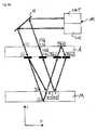
- FIGS. 5 to 7a first embodiment of the invention is shown.
- the type of representationwas analogous to the representation of the prior art in the Figures 2-4 was selected by numbering the points of incidence of the different light beams and displayed in different views of the involved interfaces. Through a synopsis of FIGS. 5 to 7 the beam path of the first embodiment can be fully understood.
- FIG. 5cshows the top (on which the light of the light source first hits) of the scale M (or a section thereof, because the scale M is in the second direction Y) with its different optical structures 03. These structures 03 are translation-invariant with respect to the second direction Y, the above-mentioned condition for a suitable scale M is thus satisfied.
- the deflecting element Uis shown, with which the light from the light source LQ is directed from the scanning head AK to the scanning rod A or from this back to the detectors DET in the scanning head AK.
- the light beams A1, A2 with the points of impingement 3d and 3cform a first partial beam A
- the light beams B1, B2 with the impact points 3a and 3bform a second partial beam B.
- the two partial beams A1, A2 and B1, B2each run asymmetrically with respect to a plane on which the measuring direction X is perpendicular, and which contains the point of impingement 2, as is best shown in the unfolded optical path of the Figure 7a can take.
- optical structure 04which contains the impact points 4a - 4d
- mirrorwhich contains the impact points 5a - 5d
- further diffractive cylindrical lensoptical structure 04, the impact points 6a - 6d contains
- the partial beams of the two partial beams A, Bare combined and brought to interference.
- two light beamsthen leave the scanning rod A in the direction of the deflecting element U, from which the required periodic signals can be obtained in a known manner.
- a disadvantage of the different path lengths and thus the phase difference of the partial beams within a partial beamis that even changes in the wavelength of light lead to periodic signals in the detectors of the scanning AK.
- a possibilityis shown of at least reducing the wavelength dependence of the position measurements (X and d) by disappearing the phase difference of the partial beams brought into interference at the operating point, that is to say at the desired sampling distance.
- FIGS. 8-10the second embodiment of the invention is shown.
- the type of representationwas analogous to the representation of the first embodiment in the FIGS. 5 to 7 was selected by numbering the points of incidence of the different light beams and displayed in different views of the involved interfaces. Through a synopsis of FIGS. 8-10 the beam path of the second embodiment can be fully understood.
- the topshows the scale M (or a portion thereof, because the scale M is extended in the second direction Y) with its various optical structures 01, 02, 03. These structures are again translation invariant with respect to the second direction Y.
- FIGS. 9a and 9bthe deflecting element U is shown, with which the light from the light source LQ is directed from the scanning head AK to the scanning rod A or from this back to the detectors DET in the scanning head AK.
- FIGS. 9b and 10acan take place at the impact point 2 on the underside of the sensing rod A first a split into 3 partial beams instead, two of which arrive at the impact points 5a and 5c on the top of the scale M, where they are reflected on a grid back to the sensing rod A.
- the third sub-beamfalls through a transparent area on the upper side of the scale (impact point 3) on a mirrored area on the back of the scale M (point of impact 4), is reflected there and leaves the scale M at the front in impact point 5b. If one compares the phase position of the partial beams in the points of impingement 5a, 5b and 5c, then all partial beams have traveled an equally long distance.
- the partial beam of impact point 5bis split only at the point of impact 8b and then forms the partial beam A2 of the partial beam A and the Sub-beam B2 of the partial beam B. These both return equally long paths.
- the phase differencedisappears only for a certain sampling distance d, the operating point. Changes in the wavelength of the light do not falsify the position measurement at the operating point. If the scanning distance d changes, the phase difference of the partial beams within the partial beams A, B nevertheless changes and the detectors generate periodic signals. By subtracting the position change produced from the partial beams A and B, the change of the scanning distance d is again obtained.
- FIG. 10aAlso in this embodiment can be seen in FIG. 10a the asymmetry of the partial beams within a partial beam A, B, and the symmetry between the two partial beams A, B, each with respect to a plane perpendicular to the measuring direction X.
- a device for compensating for tilting of the sensing rod AThe sub-beams pass through a first diffractive cylindrical lens at the points of impact 6a, 6b, 6c, which focuses the light on a mirror at the points of impact 7a, 7b, 7c, from where the light travels to the second diffractive cylindrical lens in the impingement points 8a, 8b, 8c.
- the second cylindrical lensstill fulfills a second function.
- the middle sub-beamwhich has covered the additional path through the scale substrate, is divided into sub-beams A2 and B2 only at impact point 8b.
- the optical structure 05has a first variable periodicity in the Y direction and a second constant Periodicity in the X direction.
- a cross grid or a checkerboard patternarises locally, whose period is variable in the Y direction, but constant in the X direction. This also fulfills this optical Structure 05 the important condition that it is periodically in the X direction, it can therefore be applied to a sampling bar A in any length.
- each periodicity or frequency in a gridgenerates its own diffraction orders, the intensity in the individual diffraction orders and thus in the partial beams decreases with the number of periodicities present.
- Transparent areas O1 and mirror areas 02do not contain any periodicities, one-dimensional grids 03 contain a periodicity (this also applies in the case of local viewing if the grating period is locally variable). Only the optical structure 05 of the second embodiment contains - when viewed locally - two periodicities.
- This boundary conditioncauses, for example, that in individual interfaces of scanning plate A or scale M not too many functions such as splitting or merging partial beams, aligning partial beams or focusing of partial beams can be placed, but the required functionalities must be distributed so that the condition locally to have a maximum of two periodicities or frequencies in the optical structures O1 - 05, can be met.
- the retroreflection required to compensate for tilting movementstakes place in the scanning rod A.
- the term sensing rod A and scale Mis arbitrary, ultimately, it is two crossed measuring scales, one of which must be at least partially transparent and the other at least partially reflective.
- the sensing rod Aextends in the measuring direction X and therefore carries grids with lines transverse to the measuring direction X and transverse to its extension direction.
- the sensing rod Acan also be arranged transversely to the measuring direction X, if it carries grating lines parallel to its extension direction, as for example in the FIG. 6 the cited above WO 2008/138501 A1 is shown. The line direction of the scale grid is then also rotated accordingly.
- the two dimensional scales sensing bar A and scale Mneed not necessarily be linear. As long as both define a plane, it is conceivable that one of the two directions X, Y represents a circular arc or other curved path relative to which a displacement is to be measured. In this way, for example, a path on a circular arc and thus an angle can be measured.
- a light beamleaves the scanning plate in the direction of the detector.
- several phase-shifted signalsmust be formed in several detectors for each partial beam. Either different diffraction orders are used for this than the two drawn beams, or corresponding light beams for the detectors are generated by means of additional phase-shifting elements, polarizers and beam splitters in the beam path. Such measures are customary and will not be described here.
Landscapes
- Physics & Mathematics (AREA)
- General Physics & Mathematics (AREA)
- Optical Transform (AREA)
- Length Measuring Devices By Optical Means (AREA)
Description
Translated fromGermanDie Erfindung betrifft eine optische Positionsmesseinrichtung zur Erfassung der Relativposition von zwei zueinander beweglichen Objekten. Insbesondere betrifft die Erfindung solche Positionsmesseinrichtungen, bei denen Maßverkörperungen mit optischen Gittern zum Einsatz kommen, die einfallendes Licht durch Beugung in unterschiedliche Teilstrahlen aufspalten. Durch Vereinigung geeigneter Teilstrahlen ergeben sich bei einer Verschiebung der einen Maßverkörperung gegenüber der anderen durch die Interferenz der beiden Teilstrahlen periodische Signale in einem Fotodetektor. Durch Zählen der Perioden im Detektor kann auf das Ausmaß der Verschiebung geschlossen werden.The invention relates to an optical position measuring device for detecting the relative position of two mutually movable objects. In particular, the invention relates to such position measuring devices, in which Maßverkörperungen with optical grids are used, which split incident light by diffraction into different partial beams. By combining suitable partial beams resulting in a shift of a material measure over the other by the interference of the two partial beams periodic signals in a photodetector. By counting the periods in the detector can be concluded that the extent of the shift.
Solche interferentiellen Positionsmesseinrichtungen werden für hochgenaue Positionsmessungen etwa in der Halbleiterindustrie eingesetzt, wo beispielsweise Belichtungsmasken für die Fotolithographie relativ zu einem Wafer mit Geschwindigkeiten von mehr als einem Meter pro Sekunde bewegt werden müssen, wobei eine Positioniergenauigkeit im Nanometer - Bereich und künftig auch darunter eingehalten werden muss. Ein großer Vorteil solcher Systeme gegenüber herkömmlichen Interferometern ist, dass die interferierenden Teilstrahlen nur sehr kurze Wege zurücklegen müssen, und damit kaum durch Umwelteinflüsse wie Luftdruck-, Temperatur- und Feuchtigkeitsschwankungen beeinträchtigt werden, die über einen schwankenden Brechungsindex der Luft die Messung verfälschen könnten.Such interferential position-measuring devices are used for high-precision position measurements, for example in the semiconductor industry, where, for example, exposure masks for photolithography must be moved relative to a wafer at speeds of more than one meter per second, with positioning accuracy in the nanometer range and, in the future, even below that , A major advantage of such systems over conventional interferometers is that the interfering partial beams only have to travel very short distances, and thus are hardly affected by environmental influences such as changes in atmospheric pressure, temperature and humidity, which could falsify the measurement via a fluctuating refractive index of the air.
Aus der
Nachteilig an der in der
Um die Position eines Tisches in der Tischebene zu erfassen, sind auch Messanordnungen mit Kreuzgittern bekannt, die an mehreren Stellen abgetastet werden und so laterale Verschiebungen und eine Drehung in der Tischebene erfassen können. In der
In der
Letztlich werden solche Teilstrahlen miteinander vereinigt, die miteinander interferieren und so bei einer Relativbewegung zwischen Maßverkörperung und Abtastkopf periodische Signale in mehreren Fotodetektoren erzeugen. Dank der asymmetrischen Anordnung der Teilstrahlen erhält man in den Detektoren periodische Signale, denen man sowohl die horizontale als auch die vertikale Verschiebung von Maßverkörperung und Abtastkopf entnehmen kann, und damit die laterale und vertikale Verschiebung der beiden zueinander beweglichen Objekte.Ultimately, such partial beams are combined with each other, which interfere with each other and thus generate periodic signals in a plurality of photodetectors in a relative movement between the measuring scale and the scanning head. Thanks to the asymmetrical arrangement of the partial beams, periodic signals are obtained in the detectors, from which both the horizontal and the vertical displacement of the measuring scale and scanning head can be seen, and thus the lateral and vertical displacement of the two mutually movable objects.
Aufgrund der Struktur der Abtastplatte des in der
Aufgabe der Erfindung ist es daher, eine optische Positionsmesseinrichtung mit zwei gekreuzten Maßstäben so weiter zu entwickeln, dass eine zusätzliche Messung des Abtastabstandes zwischen den beiden Maßstäben ermöglicht wird.The object of the invention is therefore to further develop an optical position-measuring device with two crossed scales so that an additional measurement of the scanning distance between the two scales is made possible.
Diese Aufgabe wird gelöst durch eine Vorrichtung mit den Merkmalen des Anspruches 1. Vorteilhafte Ausführungsformen ergeben sich aus den Merkmalen, die in den von Anspruch 1 abhängigen Ansprüchen aufgeführt sind.This object is achieved by a device having the features of
Es wird eine optische Positionsmesseinrichtung beschrieben, mit einem Abtaststab und einem Maßstab, wobei der Abtaststab in eine erste oder zweite von zwei Richtungen und der Maßstab in die jeweils andere der beiden Richtungen erstreckt ist, wobei der Maßstab in einer dritten Richtung senkrecht zur ersten und zweiten Richtung um einen Abtastabstand zum Abtaststab versetzt angeordnet ist. Die optische Positionsmesseinrichtung weist ferner eine Lichtquelle auf, deren Licht den Abtaststab an einem Kreuzungspunkt von Abtaststab und Maßstab durchstößt, um auf den Maßstab zu fallen und von dort zurück zum Abtaststab und weiter zu einem Detektor zu gelangen, wobei das Licht an optisch wirksamen Strukturen von Abtaststab und Maßstab durch Beugung in unterschiedliche Teilstrahlen aufgespalten und wieder vereinigt wird, wobei durch Interferenz von miteinander vereinigten Teilstrahlen bei einer Verschiebung zwischen Abtaststab und Maßstab in der ersten Richtung ein periodisches Signal im Detektor entsteht. Die optische Positionsmesseinrichtung ist dabei so ausgebildet, dass bei einer Änderung des Abtastabstandes zwischen Abtaststab und Maßstab ebenfalls periodische Signale im Detektor entstehen.There is described an optical position measuring device having a sensing rod and a scale, wherein the sensing rod is extended in a first or second of two directions and the scale in the other of the two directions, wherein the scale in a third direction perpendicular to the first and second Direction is arranged offset by a scanning distance to the Abtaststab. The optical position measuring device further comprises a light source, the light of which pierces the sensing rod at a crossing point of the sensing rod and scale to fall on the scale and from there back to the sensing rod and on to a detector, the light on optically active structures of Scanning rod and scale is split by diffraction into different sub-beams and reunited, whereby a periodic signal is formed in the detector by interference of sub-beams combined with a shift between the sensing rod and scale in the first direction. The optical position-measuring device is designed so that when a change in the scanning distance between the scanning rod and scale also periodic signals arise in the detector.
Dies wird erreicht, indem einzelne Teilstrahlen Gruppen bilden, wobei die Teilstrahlen einer ersten Gruppe und die Teilstrahlen einer zweiten Gruppe untereinander einen vom Abtastabstand abhängigen Phasenunterschied aufweisen.This is achieved by individual sub-beams forming groups, wherein the sub-beams of a first group and the sub-beams of a second group with each other have a dependent on the scanning distance phase difference.
Hierzu können die Teilstrahlen der ersten Gruppe bzw. die Teilstrahlen der zweiten Gruppe jeweils untereinander einen asymmetrischen Verlauf bezüglich einer Ebene senkrecht zur ersten Richtung aufweisen.For this purpose, the sub-beams of the first group and the sub-beams of the second group may each have an asymmetrical course relative to a plane perpendicular to the first direction.
Die optischen Strukturen auf dem Abtaststab sind vorzugsweise periodisch oder translationsinvariant bezüglich der ersten Richtung, damit der Abtaststab über den gesamten Verfahrweg in der ersten Richtung ausgedehnt werden kann.The optical structures on the sensing bar are preferably periodic or translation-invariant with respect to the first direction so that the sensing bar can be extended over the entire travel in the first direction.
Die optischen Strukturen auf dem Maßstab sind vorzugsweise periodisch oder translationsinvariant bezüglich der zweiten Richtung, damit der Maßstab über den gesamten Verfahrweg in der zweiten Richtung ausgedehnt werden kann.The optical structures on the scale are preferably periodic or translation invariant with respect to the second direction so that the scale can be extended over the entire travel in the second direction.
Um Detektorsignale ausreichender Qualität zu erhalten, sollten die optischen Strukturen außerdem lokal nicht mehr als zwei Periodizitäten aufweisen.In addition, to obtain detector signals of sufficient quality, the optical structures should not have locally more than two periodicities.
Weitere Vorteile sowie Einzelheiten der vorliegenden Erfindung ergeben sich aus der nachfolgenden Beschreibung bevorzugter Ausführungsformen anhand der Figuren. Dabei zeigen
- Figuren 1 - 4
- eine optische Positionsmesseinrichtung nach dem Stand der Technik,
- Figuren 5 - 7
- ein erstes Ausführungsbeispiel,
- Figuren 8 - 10
- ein zweites Ausführungsbeispiel.
- Figures 1 - 4
- an optical position measuring device according to the prior art,
- FIGS. 5 to 7
- a first embodiment,
- FIGS. 8-10
- a second embodiment.
In der
Um die Lage des Tisches T sowohl in der ersten Richtung X als auch in der zweiten Richtung Y erfassen zu können, und um außerdem auch eine Verdrehung des Tisches um eine Z - Achse senkrecht zur ersten und zweiten Richtung X, Y ermitteln zu können, sind drei dieser optischen Positionsmesseinrichtungen am Tisch T angeordnet. Betrachtet wird im Folgenden nur die in der
Die
In einem Abtastkopf AK ist eine Lichtquelle LQ angeordnet, deren Licht zunächst auf einen Umlenkspiegel U fällt, der parallel zum Abtaststab A an der Tischkante angeordnet ist. Von dort fällt das Licht durch den transparenten Abtaststab A auf den reflektierenden Maßstab M, und weiter auf einem parallel zum Hinweg versetzten Rückweg zurück in den Abtastkopf AK, in dem mehrere Detektoren DET das einfallende Licht in elektrische Signale umwandeln. Diese Signale sind bei einer Verschiebung des Tisches T in Messrichtung X periodisch. Die Anzahl der Perioden, die durch Interpolation erhöht werden kann, ist ein Maß für die Verschiebung des Tisches T. Durch die Erzeugung mehrerer, gegeneinander phasenverschobener Signale (z.B. 0/90 Grad oder 0/120/240 Grad Phasenversatz) kann außerdem eine Richtungsinformation gewonnen werden.In a scanning AK a light source LQ is arranged, the light of which initially falls on a deflection mirror U, which is arranged parallel to the sensing rod A at the table edge. From there, the light passes through the transparent sensing rod A on the reflecting scale M, and further on a return path offset parallel to the way back into the scanning AK, in which a plurality of detectors DET convert the incident light into electrical signals. These signals are periodic with a displacement of the table T in the measuring direction X. The number of periods that can be increased by interpolation is a measure of the displacement of the table T. By generating a plurality of mutually phase-shifted signals (eg, 0/90 degrees or 0/120/240 degrees phase offset) directional information can also be obtained become.
Der Abtastkopf AK, der Maßstab M und das Werkzeug WZ sind in diesem Beispiel ortsfest, während der Tisch T mit Umlenkspiegel U, Abtaststab A und Werkstück WS gemeinsam in der Tischebene beweglich sind. Diese aus dem Stand der Technik bekannte Anordnung hat den Vorteil, dass die Messung der Lage des Tisches in der ersten Richtung X unabhängig von der Lage des Tisches in der zweiten Richtung Y möglich ist. Da die für die Positionsmessung entscheidenden Gitterstriche auf dem Abtaststab A und auf dem Maßstab M quer zur Messrichtung X liegen, bleiben bei einer Bewegung des Tisches T in der zweiten Richtung Y die Detektorsignale der Detektoren im Abtastkopf AK unverändert, und reagieren nur auf eine Bewegung in der eigentlichen Messrichtung X.The scanning head AK, the scale M and the tool WZ are stationary in this example, while the table T with deflection mirror U, sensing rod A and workpiece WS are movable together in the plane of the table. This known from the prior art arrangement has the advantage that the measurement of the position of the table in the first direction X is independent of the position of the table in the second direction Y possible. Since the grating lines which are decisive for the position measurement lie transversely to the measuring direction X on the scanning rod A and on the scale M, the detector signals of the detectors in the scanning head AK remain unchanged during a movement of the table T in the second direction Y, and react only to a movement in the actual measuring direction X.
Der Abstand zwischen dem Abtaststab A und dem Maßstab M sei hier als Abtastabstand d bezeichnet. Führt der Tisch, z.B. aufgrund von Führungsfehlern, zusätzlich eine Bewegung in der dritten Richtung Z aus, so ändert sich damit zwangläufig auch der Abtastabstand d, da der Abtaststab A mit dem Tisch T fest verbunden und der Maßstab M gegenüber dem Tisch ortsfest ist. Über die Erfassung des Abtastabstandes d ließe sich also ein weiterer Freiheitsgrad des Tisches ermitteln.The distance between the sensing rod A and the scale M is here referred to as sampling distance d. Is the table, e.g. due to guide errors, in addition to a movement in the third direction Z, it also inevitably changes the scanning distance d, since the sensing rod A is firmly connected to the table T and the scale M is stationary relative to the table. By detecting the scanning distance d, it would thus be possible to determine a further degree of freedom of the table.
Die im Stand der Technik bekannten Positionsmesseinrichtungen, die auf gekreuzten Maßverkörperungen wie in den
In den
In den
In allen Darstellungen sind die Durchtrittspunkte oder Auftreffpunkte des Lichts durch die Grenzflächen markiert und durchnummeriert. Mit jeder Wechselwirkung an einer Grenzfläche wird die Nummer eines Punktes um eins erhöht. Entstehen durch Beugung mehrere Teilstrahlen, so werden diese an den folgenden Auftreffpunkten mit a, b, c usw. benannt.In all representations, the passage points or points of impact of the light are marked and numbered by the interfaces. With every interaction at an interface, the number of a point is increased by one. If several partial beams are formed by diffraction, these are designated at the following points of impact with a, b, c, etc.
Die
Auch in den Punkten 3a und 3b trifft das Licht auf ein regelmäßiges Gitter 03, dessen Striche wie schon im Punkt 2 quer zur Messrichtung X liegen. Beide Teilstrahlen werden erneut in zwei Teilstrahlen aufgeteilt und zurück zur Unterseite der Abtastplatte APU reflektiert, wo sie in den Punkten 4a, 4b, 4c, 4d auftreffen.Also in
Um gewisse Einflüsse gegen Verkippungen zwischen Maßstab und Abtastplatte zu kompensieren, müssen die vier Teilstrahlen an dieser Stelle parallel gerichtet und gleichzeitig auf spiegelnde Strukturen 02 auf der Oberseite der Abtastplatte fokussiert werden. Hierzu weist die Unterseite der Abtastplatte APU in den Punkten 4a und 4b optische Strukturen 04 in Form eines eindimensionalen Gitters mit veränderlicher Gitterperiode auf. Diese Strukturen wirken als Zylinderlinse und fokussieren das einfallende Licht. An den Punkten 4c und 4d sind die Gitterstriche zusätzlich gekrümmt, um neben der Linsenwirkung auch eine Parallelrichtung der jeweiligen Lichtstrahlen zu erreichen.In order to compensate for certain influences against tilting between scale and scanning, the four sub-beams must be directed in parallel at this point and simultaneously focused on
In den Punkten 5a, 5b, 5c und 5d treffen die vier Teilstrahlen auf spiegelnde Flächen der Oberseite der Abtastplatte APO.In the
Von den Punkten 5a und 5b erfolgt eine weitere Reflexion zu spiegelnden Flächen 02 auf der Unterseite der Abtastplatte APU, wo das Licht in den Punkten 6a und 6b auftrifft. Von dort läuft das Licht wieder zur Oberseite der Abtastplatte APO und trifft in den Punkten 7a und 7b auf spiegelnde Flächen 02.From the
Von den spiegelnden Flächen 02 in den Punkten 5c, 5d, 7a und 7b laufen die Lichtstrahlen erneut zur Unterseite der Abtastplatte APU, wo sie in den Punkten 8a und 8b auf eindimensionale Gitter 04 mit variabler Gitterperiode treffen, die als Zylinderlinsen wirken, bzw. in den Punkten 8c und 8d auf Strukturen, die zusätzlich zur Linsenwirkung mittels gekrümmter Gitterstriche eine Richtungsänderung der Strahlen bewirken. An den Punkten 9a und 9b auf der Oberseite der Maßverkörperung MV werden je zwei Lichtstrahlen zur Interferenz gebracht, wodurch mindestens zwei phasenverschobene Strahlenbündel erzeugt werden. Von den Punkten 9a und 9b der Maßverkörperung MV laufen die so erzeugten Lichtstrahlen zur Unterseite der Abtastplatte APU, wo sie im Punkt 10 auf das regelmäßiges Gitter 03 treffen und in eine passende Richtung abgelenkt werden. In den Punkten 11a und 11b verlassen dann zwei Lichtstrahlen die Abtastplatte an der Oberseite APO und gelangen schließlich zu Detektoren, in denen gegeneinander phasenverschobene Signale erzeugt werden.From the reflecting
Insbesondere in der
Da aber die beiden Teilstrahlenbündel A und B zueinander bezüglich besagter Ebene senkrecht zur Messrichtung X symmetrisch verlaufen, lässt sich durch eine Aufsummierung der aus den beiden Teilstrahlenbündeln gewonnen Positionsinformation die reine Verschiebung in X-Richtung bestimmen, und aus einer Differenz der beiden Positionsinformationen die Änderung des Abtastabstandes d.However, since the two partial beams A and B are symmetrical to each other with respect to said plane perpendicular to the measuring direction X, the pure displacement in the X direction can be determined by summing the position information obtained from the two partial beams, and the change of the position information from a difference of the two position information Scanning distance d.
Eine ausführliche Herleitung der physikalischen Grundlagen und der prinzipiellen Funktionsweise der Messung der des Abtastabstandes d, beruhend auf der erwähnten Asymmetrie der betrachteten Teilstrahlenbündel bezüglich einer Ebene, die Senkrecht auf der lateralen Messrichtung steht, findet sich in den Absätzen [0021] bis [0038] der eingangs bereits erwähnten
Anhand der
Hierzu ist es nämlich nötig, dass sich die Auftreffpunkte des Lichts auf dem Abtaststab A in der Messrichtung X verschieben lassen, ohne dabei die Messung zu stören. Hierzu müssen die optischen Strukturen auf dem Abtaststab A periodisch oder translationsinvariant sein bezüglich der ersten Richtung X. Translationsinvariant sind Spiegelflächen oder transparente Flächen, die in der Messrichtung, also der ersten Richtung X ausgedehnt sind, und Gitterstrukturen, deren Linien parallel zur ersten Richtung X verlaufen. Geeignete periodische optische Strukturen sind Gitterstrukturen, deren Gitterperiode sich in X-Richtung nicht ändert.For this purpose, it is necessary that the points of impact of the light on the sensing rod A in the measuring direction X can be moved without disturbing the measurement. For this purpose, the optical structures on the sensing rod A must be periodic or translationally invariant with respect to the first direction X. Translationally invariant are mirror surfaces or transparent surfaces that extend in the measuring direction, ie the first direction X. are and lattice structures whose lines are parallel to the first direction X. Suitable periodic optical structures are lattice structures whose grating period does not change in the X direction.
Im Folgenden werden zwei Ausführungsbeispiele der Erfindung beschrieben, bei denen der Abtaststab ausschließlich solche translationsinvarianten oder periodischen Strukturen trägt. Somit lässt sich eine Positionsmesseinrichtung schaffen, die gemäß der
In den
Es sei hier auf einige Besonderheiten dieses Ausführungsbeispiels eingegangen:
Die Figuren 5a und 5b zeigen die Oberseite (auf die das Licht der Lichtquelle zuerst trifft) und die Unterseite des Abtaststabes A (bzw. jeweils einen Ausschnitt davon, denn der Abtaststab A ist in der ersten Richtung X ausgedehnt) mit seinen verschiedenen optischen Strukturen O1, 02, 03, 04. Diese Strukturen sind dabei entweder translationsinvariant bezüglich der ersten Richtung (also der Messrichtung) X, wie die lichtdurchlässigen Bereiche 01, dieSpiegelflächen 02, und die eindimensionalen Gitter mit in Y-Richtung variabler Gitterperiode 04, deren Strichrichtung parallel zur Messrichtung X liegt, oder periodisch, wie die regelmäßigenGitter 03, deren Strichrichtung quer zur Messrichtung X liegen. Die oben genannte Bedingung für einen geeigneten Abtaststab A ist damit erfüllt.
- The
FIGS. 5a and 5b show the upper side (on which the light of the light source first hits) and the underside of the sensing rod A (or in each case a section thereof, since the sensing rod A is extended in the first direction X) with its various optical structures O1, 02, 03, 04. These structures are either translationally invariant with respect to the first direction (that is, the measuring direction) X, such as thetranslucent regions 01, the mirror surfaces 02, and the one-dimensional gratings with variable in the Ydirection grating period 04, the stroke direction is parallel to the measuring direction X, or periodically, such as theregular grid 03, the line direction are transverse to the measuring direction X. The above condition for a suitable sensing rod A is satisfied.
Die
In den
Vom Auftreffpunkt 2 auf der Unterseite des Abtaststabes A laufen vier Lichtstrahlen zum Maßstab M. Die Lichtstrahlen A1, A2 mit den Auftreffpunkten 3d und 3c bilden dabei ein erstes Teilstrahlenbündel A, die Lichtstrahlen B1, B2 mit den Auftreffpunkten 3a und 3b bilden ein zweites Teilstrahlenbündel B.From the
Deutlich erkennt man die Asymmetrie der Teilstrahlen A1, A2 bzw. B1, B2 innerhalb eines Teilstrahlenbündels A bzw. B, die zu unterschiedlich langen Lichtwegen zwischen den jeweiligen Teilstrahlen und damit zu einem Phasenunterschied führt, der zudem vom Abtastabstand d abhängt. Die beiden Teilstrahlen A1, A2 bzw. B1, B2 laufen jeweils asymmetrisch bzgl. einer Ebene, auf welche die Messrichtung X senkrecht steht, und die den Auftreffpunkt 2 enthält, wie man am besten dem aufgefalteten Strahlengang der
Außerdem erkennt man die Symmetrie zwischen den beiden Teilstrahlenbündeln A und B, die nötig ist, um durch Addition der Positionsinformation aus den beiden Teilstrahlenbündeln die Verschiebungsinformation in X-Richtung zu ermitteln, und durch Subtraktion die Änderung des Abtastabstandes d. Spiegelt man die beiden Teilstrahlen A1, A2 des Strahlenbündels A an besagter Ebene, so erhält man das Strahlenbündel B.In addition, one recognizes the symmetry between the two partial beams A and B, which is necessary to determine the displacement information in the X direction by adding the position information from the two partial beams, and by subtracting the change of the scanning distance d. If one reflects the two partial beams A1, A2 of the beam A at said plane, one obtains the beam B.
Wieder findet man die Kombination aus diffraktiver Zylinderlinse (optische Struktur 04, die die Auftreffpunkte 4a - 4d enthält), Spiegel (optische Struktur 02, die die Auftreffpunkte 5a - 5d enthält) und weiterer diffraktiver Zylinderlinse (optische Struktur 04, die die Auftreffpunkte 6a - 6d enthält), mit der eine Retroreflexion aller Teilstrahlen A1, A2, B1, B2 zur Kompensation von Kippbewegungen des Abtaststabes A bewirkt wird.Again one finds the combination of diffractive cylindrical lens (
An den Auftreffpunkten 8b bzw. 8a werden die Teilstrahlen der beiden Teilstrahlenbündel A, B vereinigt und zur Interferenz gebracht. An den Punkten 9a und 9b verlassen dann zwei Lichtstrahlen den Abtaststab A Richtung Umlenkelement U, aus denen sich die benötigten periodischen Signale in bekannter Weise gewinnen lassen.At the impact points 8b and 8a, the partial beams of the two partial beams A, B are combined and brought to interference. At the
Ein Nachteil der unterschiedlichen Weglängen und damit des Phasenunterschieds der Teilstrahlen innerhalb eines Teilstrahlenbündels ist, dass auch Änderungen in der Lichtwellenlänge zu periodischen Signalen in den Detektoren des Abtastkopfes AK führen.A disadvantage of the different path lengths and thus the phase difference of the partial beams within a partial beam is that even changes in the wavelength of light lead to periodic signals in the detectors of the scanning AK.
Im zweiten Ausführungsbeispiel wird eine Möglichkeit gezeigt, die Wellenlängenabhängigkeit der Positionsmessungen (X und d) zumindest zu reduzieren, indem die Phasendifferenz der zur Interferenz gebrachten Teilstrahlen im Arbeitspunkt, also im Soll - Abtastabstand, verschwindet.In the second exemplary embodiment, a possibility is shown of at least reducing the wavelength dependence of the position measurements (X and d) by disappearing the phase difference of the partial beams brought into interference at the operating point, that is to say at the desired sampling distance.
In den
Es sei wieder auf einige Besonderheiten dieses Ausführungsbeispiels eingegangen:
Die Figuren 8a bzw. 8b zeigen die Oberseite (auf die das Licht der Lichtquelle zuerst trifft) bzw. die Unterseite des Abtaststabes A (bzw. jeweils einen Ausschnitt davon, denn der Abtaststab A ist in der ersten Richtung X ausgedehnt) mit seinen verschiedenen optischen Strukturen O1, 02, 03, 04, 05. Diese Strukturen sind dabei entweder translationsinvariant bezüglich der ersten Richtung (also der Messrichtung) X, wie die lichtdurchlässigen Bereiche O1, dieSpiegelflächen 02, und die eindimensionalen Gitter mit in Y-Richtung variabler Gitterperiode 04, deren Strichrichtung parallel zur Messrichtung X liegt, oder periodisch, wie die regelmäßigenGitter 03, deren Strichrichtung quer zur Messrichtung X liegen, oder wie das zweidimensionaleGitter 05, dessen Gitterperiode in Messrichtung X konstant, aber in der zweiten Richtung Y variabel ist. Die oben genannte Bedingung für einen geeigneten Abtaststab A ist damit wiederum erfüllt.
- The
FIGS. 8b respectively show the upper side (on which the light of the light source first strikes) and the lower side of the scanning bar A (or a section thereof, since the scanning bar A is extended in the first direction X) with its different optical structures O1, 02, 03, 04, 05. These structures are either translation-invariant with respect to the first direction (ie the measuring direction) X, like the transparent areas O1, the mirror surfaces 02, and the one-dimensional gratings with variable in the Y8a direction grating period 04, the stroke direction is parallel to the measuring direction X, or periodically, such as theregular grating 03, the stroke direction transverse to the measuring direction X, or as the two-dimensional Grid 05 whose grating period is constant in the measuring direction X, but variable in the second direction Y. The above-mentioned condition for a suitable sampling bar A is thus fulfilled again.
Die
In den
Wie man insbesondere in der Zusammenschau der
Der Teilstrahl von Auftreffpunkt 5b wird erst im Auftreffpunkt 8b aufgespalten und bildet dann den Teilstrahl A2 des Teilstrahlenbündels A und den Teilstrahl B2 des Teilstrahlenbündels B. Diese legen beide wieder gleich lange Wege zurück.The partial beam of
Da der zusätzliche Weg durch den Maßstab M fest ist, verschwindet der Phasenunterschied nur für einen bestimmten Abtastabstand d, dem Arbeitspunkt. Wellenlängenänderungen des Lichts verfälschen damit im Arbeitspunkt die Positionsmessung nicht. Ändert sich der Abtastabstand d, so ändert sich dennoch der Phasenunterschied der Teilstrahlen innerhalb der Teilstrahlenbündel A, B und die Detektoren erzeugen periodische Signale. Durch Differenzbildung der aus den Teilstrahlen A und B erzeugten Positionsänderung erhält man wieder die Änderung des Abtastabstandes d.Since the additional path is fixed by the scale M, the phase difference disappears only for a certain sampling distance d, the operating point. Changes in the wavelength of the light do not falsify the position measurement at the operating point. If the scanning distance d changes, the phase difference of the partial beams within the partial beams A, B nevertheless changes and the detectors generate periodic signals. By subtracting the position change produced from the partial beams A and B, the change of the scanning distance d is again obtained.
Auch in diesem Ausführungsbeispiel erkennt man in
Man erkennt auch in diesem Ausführungsbeispiel eine Einrichtung zur Kompensation von Kippbewegungen des Abtaststabes A: Die Teilstrahlen durchlaufen eine erste diffraktive Zylinderlinse an den Auftreffpunkten 6a, 6b, 6c, die das Licht auf einen Spiegel an den Auftreffpunkten 7a, 7b, 7c fokussiert, von wo das Licht zur zweiten diffraktiven Zylinderlinse in den Auftreffpunkten 8a, 8b, 8c wandert.It can be seen in this embodiment, a device for compensating for tilting of the sensing rod A: The sub-beams pass through a first diffractive cylindrical lens at the points of
Die zweite Zylinderlinse erfüllt dabei noch eine zweite Funktion. Wie bereits oben erwähnt, wird der mittlere Teilstrahl, der den zusätzlichen Weg durch das Maßstabssubstrat zurückgelegt hat, erst im Auftreffpunkt 8b in die Teilstrahlen A2 bzw. B2 aufgeteilt.The second cylindrical lens still fulfills a second function. As already mentioned above, the middle sub-beam, which has covered the additional path through the scale substrate, is divided into sub-beams A2 and B2 only at
Um an den Auftreffpunkten 8a, 8b, 8c für die Teilstrahlenbündel A und B eine gemeinsame Linsenwirkung in Y-Richtung bei gleichzeitig unterschiedlicher Beugung in X-Richtung zu erzeugen, weist die optische Struktur 05 eine erste veränderliche Periodizität in Y-Richtung und eine zweite konstante Periodizität in X-Richtung auf. Es entsteht also lokal ein Kreuzgitter oder ein Schachbrettmuster, dessen Periode in Y-Richtung variabel, in X-Richtung jedoch konstant ist. Damit erfüllt auch diese optische Struktur 05 die wichtige Bedingung, dass sie periodisch in X-Richtung ist, sie kann daher auf einem Abtaststab A in beliebiger Länge aufgebracht werden.In order to produce a common lens action in the Y direction at the
Da jede Periodizität oder Frequenz in einem Gitter eigene Beugungsordnungen erzeugt, nimmt die Intensität in den einzelnen Beugungsordnungen und damit in den Teilstrahlen mit der Anzahl der vorhandenen Periodizitäten ab. Um gute Signale in den Detektoren DET zu bekommen, sollte darauf geachtet werden, dass die verwendeten optischen Strukturen O1-O5 lokal maximal zwei Periodizitäten oder Frequenzen aufweisen. Diese Randbedingung ist in beiden Ausführungsbeispielen erfüllt. Transparente Bereiche O1 und Spiegelflächen 02 enthalten gar keine Periodizitäten, eindimensionale Gitter 03 enthalten eine Periodizität (das gilt bei lokaler Betrachtung auch, wenn die Gitterperiode örtlich veränderlich ist). Einzig die optische Struktur 05 des zweiten Ausführungsbeispiels enthält - bei lokaler Betrachtung - zwei Periodizitäten.Since each periodicity or frequency in a grid generates its own diffraction orders, the intensity in the individual diffraction orders and thus in the partial beams decreases with the number of periodicities present. In order to obtain good signals in the detectors DET, care should be taken that the optical structures O1-O5 used have a maximum of two periodicities or frequencies locally. This boundary condition is met in both embodiments. Transparent areas O1 and
Diese Randbedingung bewirkt beispielsweise, dass in einzelnen Grenzflächen von Abtastplatte A oder Maßstab M nicht zu viele Funktionen wie Aufspalten oder Vereinigen von Teilstrahlen, Ausrichten von Teilstrahlen oder Fokussieren von Teilstrahlen gelegt werden können, vielmehr müssen die benötigen Funktionalitäten so verteilt werden, dass die Bedingung, lokal maximal zwei Periodizitäten bzw. Frequenzen in den optischen Strukturen O1 - 05 zu haben, erfüllt werden kann.This boundary condition causes, for example, that in individual interfaces of scanning plate A or scale M not too many functions such as splitting or merging partial beams, aligning partial beams or focusing of partial beams can be placed, but the required functionalities must be distributed so that the condition locally to have a maximum of two periodicities or frequencies in the optical structures O1 - 05, can be met.
In beiden beschrieben Ausführungsbeispielen findet die zur Kompensation von Kippbewegungen nötige Retroreflexion im Abtaststab A statt. Es ist natürlich auch möglich, diese Funktion im Maßstab M zu verwirklichen. Auch ist die Bezeichnung Abtaststab A und Maßstab M willkürlich, letztlich handelt es sich um zwei gekreuzte Maßverkörperungen, von denen eine zumindest teilweise transparent und die andere zumindest teilweise reflektierend sein muss.In both exemplary embodiments described, the retroreflection required to compensate for tilting movements takes place in the scanning rod A. Of course, it is also possible to realize this function in scale M. Also, the term sensing rod A and scale M is arbitrary, ultimately, it is two crossed measuring scales, one of which must be at least partially transparent and the other at least partially reflective.
In den Ausführungsbeispielen ist der Abtaststab A in Messrichtung X erstreckt und trägt deshalb Gitter mit Strichen quer zur Messrichtung X und quer zu seiner Erstreckungsrichtung. Der Abtaststab A lässt sich aber auch quer zur Messrichtung X anordnen, wenn er Gitterstriche parallel zu seiner Erstreckungsrichtung trägt, wie dies zum Beispiel in der
Die beiden Maßverkörperungen Abtaststab A und Maßstab M müssen auch nicht notwendigerweise linear sein. Solange beide eine Ebene definieren ist es vorstellbar, dass eine der beiden Richtungen X, Y einen Kreisbogen oder eine andere gekrümmte Bahn darstellt, relativ zu der eine Verschiebung gemessen werden soll. Auf diese Weise kann beispielsweise ein Weg auf einem Kreisbogen und damit ein Winkel gemessen werden.Also, the two dimensional scales sensing bar A and scale M need not necessarily be linear. As long as both define a plane, it is conceivable that one of the two directions X, Y represents a circular arc or other curved path relative to which a displacement is to be measured. In this way, for example, a path on a circular arc and thus an angle can be measured.
In allen Ausführungsbeispielen verlassen gemäß der Figuren nach der Vereinigung der Teilstrahlen A1, A2, bzw. B1, B2 pro Teilstrahlenbündel A, B ein Lichtstrahl die Abtastplatte Richtung Detektor. Dort müssen aber pro Teilstrahlenbündel jeweils mehrere phasenverschobene Signale in mehreren Detektoren gebildet werden. Entweder werden hierzu noch andere Beugungsordnungen als die beiden gezeichneten Strahlen herangezogen, oder es werden mittels zusätzlicher phasenschiebender Elemente, Polarisatoren und Strahlteiler im Strahlengang entsprechende Lichtstrahlen für die Detektoren erzeugt. Solche Maßnahmen sind fachüblich und werden hier nicht näher ausgeführt.In all embodiments, according to the figures after the union of the partial beams A1, A2, or B1, B2 per partial beam A, B, a light beam leaves the scanning plate in the direction of the detector. There, however, several phase-shifted signals must be formed in several detectors for each partial beam. Either different diffraction orders are used for this than the two drawn beams, or corresponding light beams for the detectors are generated by means of additional phase-shifting elements, polarizers and beam splitters in the beam path. Such measures are customary and will not be described here.
Es ist vorteilhaft, vor der zur Kompensation von Nickbewegungen benötigten Retroreflexion mittels diffraktiver Zylinderlinsen und Spiegel alle beteiligten Teilstrahlen parallel oder zumindest so auszurichten, dass die Richtungskomponenten in Messrichtung X betragsmäßig gleich sind, da dann für alle Teilstrahlen die gleichen Zylinderlinsen verwendet werden können.It is advantageous, in front of the retroreflection required to compensate for pitching movements by means of diffractive cylindrical lenses and mirrors, to align all participating partial beams parallel or at least in such a way that the directional components in the measuring direction X are equal in magnitude, since then the same cylindrical lenses can be used for all partial beams.
Claims (14)
- Optical position measuring device having a sampling strip (A) and a measuring strip (M), wherein the sampling strip (A) extends in a first or second of two directions (X, Y) and the measuring strip (M) extends in the respective other of the two directions (X, Y), and wherein the measuring strip (M) in a third direction (Z) is arranged offset from the sampling strip (A) by a sampling distance (d) perpendicular to the first and second directions (X, Y), and having a light source, the light of which pierces through the sampling strip (A) at an intersection of sampling strip (A) and measuring strip (M) so as to be incident on the measuring strip (M) and to pass from there back to the sampling strip (A) and further on to a detector, wherein the light is split up by diffraction into various partial beams (A1, A2, B1, B2) at optical structures (O1, 02, 03, 04, 05) of sampling strip (A) and measuring strip (M) and reunited, wherein, in the case of a displacement between sampling strip (A) and measuring strip (M) in the first direction (X), periodic detector signals are generated due to interference of the united partial beams (A1, A2, B1, B2),characterized in that periodic detector signals are generated even if the sampling distance (d) between sampling strip (A) and measuring strip (M) changes.
- Optical position measuring device according to Claim 1,characterized in that the detector signals remain unchanged in the case of a displacement between sampling strip (A) and measuring strip (M) in the second direction (Y).
- Optical position measuring device according to Claim 1 or 2,characterized in that the partial beams (A1, A2, B1, B2) form groups (A, B), wherein the partial beams (A1, A2) of a first group (A) and the partial beams (B1, B2) of a second group (R) have, among them, a phase difference which is dependant on the sampling distance (d).
- Optical position measuring device according to Claim 3,characterized in that the phase difference disappears for a specific sampling distance (d).
- Optical position measuring device according to Claim 4,characterized in that in each case one partial beam (A1, B1) within each group (A, B) travels an additional path within a transparent substrate of the measuring strip (M) or of the sampling strip (A).
- Optical position measuring device according to Claim 3, 4 or 5,characterized in that the partial beams (A1, A2) of the first group (A) extend mirror-symmetrically to the partial beams (B1, B2) of the second group (B) with respect to a plane perpendicular to the first direction (X).
- Optical position measuring device according to Claim 3, 4, 5 or 6,characterized in that the partial beams (A1, A2) of the first group (A) and the partial beams (B1, B2) of the second group (B) have, among them, an asymmetrical profile with respect to a plane perpendicular to the first direction (X).
- Optical position measuring device according to one of Claims 3-7,characterized in that the partial beams (A1, A2, B1, B2) undergo retroreflection.
- Optical position measuring device according to Claim 8,characterized in that the partial beams (A1, A2, B1, B2) extend in parallel before and after the retroreflection.
- Optical position measuring device according to Claim 8 or 9,characterized in that the retroreflection is effected using at least one diffractive lens (O4, O5) and a mirror surface (O2).
- Optical position measuring device according to one of Claims 3-10,characterized in that in each case mutually phase-shifted detector signals are produced from the interfering partial beams (A1 A2, B1, B2) of each group (A, B), wherein the displacement between sampling strip (A) and measuring strip (M) in the first direction (X), on the one hand, and the change of the sampling distance (d), on the other hand, can be ascertained by way of a different combination of the detector signals of the first group (A) and the second group (B).
- Optical position measuring device according to one of the preceding claims,characterized in that the optical structures (O1, 02, 03, 04, 05) on the sampling strip (A) are periodic or translation-invariant with respect to the first direction (X).
- Optical position measuring device according to one of the preceding claims,characterized in that the optical structures (O1, O2, O3, O4, O5) on the measuring strip (M) are periodic or translation-invariant with respect to the second direction (Y).
- Optical position measuring device according to Claim 12 or 13,characterized in that the optical structures (O1, O2, O3, O4, O5) locally have a maximum of two periodicities.
Applications Claiming Priority (1)
| Application Number | Priority Date | Filing Date | Title |
|---|---|---|---|
| DE201010043469DE102010043469A1 (en) | 2010-11-05 | 2010-11-05 | Optical position measuring device |
Publications (3)
| Publication Number | Publication Date |
|---|---|
| EP2450673A2 EP2450673A2 (en) | 2012-05-09 |
| EP2450673A3 EP2450673A3 (en) | 2012-11-14 |
| EP2450673B1true EP2450673B1 (en) | 2013-12-11 |
Family
ID=44785725
Family Applications (1)
| Application Number | Title | Priority Date | Filing Date |
|---|---|---|---|
| EP11185422.0AActiveEP2450673B1 (en) | 2010-11-05 | 2011-10-17 | Optical positioning device |
Country Status (5)
| Country | Link |
|---|---|
| US (1) | US8822907B2 (en) |
| EP (1) | EP2450673B1 (en) |
| JP (1) | JP5882672B2 (en) |
| CN (1) | CN102455192B (en) |
| DE (1) | DE102010043469A1 (en) |
Cited By (3)
| Publication number | Priority date | Publication date | Assignee | Title |
|---|---|---|---|---|
| DE102015218702A1 (en) | 2015-09-29 | 2017-03-30 | Dr. Johannes Heidenhain Gmbh | Optical layer system |
| EP3438618A1 (en) | 2017-08-02 | 2019-02-06 | Dr. Johannes Heidenhain GmbH | Scanner disk for an optical position measuring device |
| EP3869161B1 (en)* | 2020-02-19 | 2022-12-21 | Dr. Johannes Heidenhain GmbH | Optical positioning device |
Families Citing this family (7)
| Publication number | Priority date | Publication date | Assignee | Title |
|---|---|---|---|---|
| DE102013211758A1 (en)* | 2013-06-21 | 2014-12-24 | Dr. Johannes Heidenhain Gmbh | interferometer |
| DE102013221898A1 (en)* | 2013-10-29 | 2015-04-30 | Dr. Johannes Heidenhain Gmbh | Device for determining position |
| DE102015219810A1 (en) | 2015-10-13 | 2017-04-13 | Dr. Johannes Heidenhain Gmbh | X-Y table with a position measuring device |
| CN107192349B (en)* | 2016-03-14 | 2020-10-16 | 松下知识产权经营株式会社 | Light detection device |
| TW201741618A (en) | 2016-05-23 | 2017-12-01 | 國立交通大學 | Optical detecting device |
| JP7182522B2 (en)* | 2019-06-27 | 2022-12-02 | Dmg森精機株式会社 | detector |
| CN114894100B (en)* | 2022-05-12 | 2023-06-23 | 李里 | Displacement detection device |
Family Cites Families (14)
| Publication number | Priority date | Publication date | Assignee | Title |
|---|---|---|---|---|
| US5171999A (en)* | 1989-02-28 | 1992-12-15 | Nikon Corporation | Adjustable beam and interference fringe position |
| DE59203396D1 (en)* | 1992-07-18 | 1995-09-28 | Heidenhain Gmbh Dr Johannes | Optical device. |
| EP0669518B1 (en)* | 1994-02-23 | 2000-01-19 | Dr. Johannes Heidenhain GmbH | Device to generate position dependant signals |
| WO1999017073A1 (en)* | 1997-09-29 | 1999-04-08 | Dr. Johannes Heidenhain Gmbh | Device for detecting the position of two bodies |
| US6351313B1 (en) | 1997-09-29 | 2002-02-26 | Dr. Johannes Heidenhain Gmbh | Device for detecting the position of two bodies |
| DE102005029917A1 (en)* | 2005-06-28 | 2007-01-04 | Dr. Johannes Heidenhain Gmbh | Position measuring device |
| DE102005043569A1 (en) | 2005-09-12 | 2007-03-22 | Dr. Johannes Heidenhain Gmbh | Position measuring device |
| JP2009509156A (en)* | 2005-09-21 | 2009-03-05 | コーニンクレッカ フィリップス エレクトロニクス エヌ ヴィ | System for detecting the motion of an object |
| WO2007077855A1 (en)* | 2005-12-28 | 2007-07-12 | Nikon Corporation | Encoder |
| US7858922B2 (en)* | 2006-11-20 | 2010-12-28 | Dr. Johannes Heidenhain Gmbh | Position-measuring device |
| DE102008008873A1 (en)* | 2007-05-16 | 2008-11-20 | Dr. Johannes Heidenhain Gmbh | Position measuring device |
| DE102007023300A1 (en)* | 2007-05-16 | 2008-11-20 | Dr. Johannes Heidenhain Gmbh | Position measuring device and arrangement thereof |
| DE102008007319A1 (en)* | 2008-02-02 | 2009-08-06 | Dr. Johannes Heidenhain Gmbh | Optical position measuring device |
| JP5268529B2 (en)* | 2008-09-29 | 2013-08-21 | キヤノン株式会社 | Displacement measuring device and semiconductor manufacturing device |
- 2010
- 2010-11-05DEDE201010043469patent/DE102010043469A1/ennot_activeWithdrawn
- 2011
- 2011-10-10CNCN201110304952.9Apatent/CN102455192B/enactiveActive
- 2011-10-17EPEP11185422.0Apatent/EP2450673B1/enactiveActive
- 2011-10-21JPJP2011231341Apatent/JP5882672B2/enactiveActive
- 2011-11-02USUS13/288,007patent/US8822907B2/enactiveActive
Cited By (7)
| Publication number | Priority date | Publication date | Assignee | Title |
|---|---|---|---|---|
| DE102015218702A1 (en) | 2015-09-29 | 2017-03-30 | Dr. Johannes Heidenhain Gmbh | Optical layer system |
| EP3150970A1 (en) | 2015-09-29 | 2017-04-05 | Dr. Johannes Heidenhain GmbH | Optical layer system |
| US10094961B2 (en) | 2015-09-29 | 2018-10-09 | Dr. Johannes Heidenhain Gmbh | Optical layer system |
| EP3438618A1 (en) | 2017-08-02 | 2019-02-06 | Dr. Johannes Heidenhain GmbH | Scanner disk for an optical position measuring device |
| DE102017213330A1 (en) | 2017-08-02 | 2019-02-07 | Dr. Johannes Heidenhain Gmbh | Scanning plate for an optical position measuring device |
| US10914615B2 (en) | 2017-08-02 | 2021-02-09 | Dr. Johannes Heidenhain Gmbh | Scanning reticle including a grating formed in a substrate for an optical position measuring device |
| EP3869161B1 (en)* | 2020-02-19 | 2022-12-21 | Dr. Johannes Heidenhain GmbH | Optical positioning device |
Also Published As
| Publication number | Publication date |
|---|---|
| US8822907B2 (en) | 2014-09-02 |
| EP2450673A2 (en) | 2012-05-09 |
| JP5882672B2 (en) | 2016-03-09 |
| DE102010043469A1 (en) | 2012-05-10 |
| CN102455192B (en) | 2016-05-18 |
| JP2012103245A (en) | 2012-05-31 |
| EP2450673A3 (en) | 2012-11-14 |
| US20120112050A1 (en) | 2012-05-10 |
| CN102455192A (en) | 2012-05-16 |
Similar Documents
| Publication | Publication Date | Title |
|---|---|---|
| EP2450673B1 (en) | Optical positioning device | |
| EP1762828B1 (en) | Optical encoder for determining the position of two parts that are movable relative to one another in two directions of movement | |
| EP1901041B1 (en) | Position measuring device | |
| EP2149029B1 (en) | Position measuring device | |
| EP2848899B1 (en) | Optical positioning device | |
| EP2450672B1 (en) | Optical angle measuring apparatus | |
| EP2623937B1 (en) | Position measuring device and assembly with multiple position measuring devices | |
| DE102008007319A1 (en) | Optical position measuring device | |
| DE102010003157A1 (en) | Device for interferential distance measurement | |
| EP3059554B1 (en) | Optical positioning device | |
| EP2746731B1 (en) | Optical position measurement device | |
| EP1992915B1 (en) | Position measuring device | |
| EP3477264A1 (en) | Optical positioning device | |
| DE102011005937B4 (en) | Device for interferential distance measurement | |
| EP3869161B1 (en) | Optical positioning device | |
| EP2869034A1 (en) | Position sensing device | |
| DE112014001977B4 (en) | Device for interferential distance measurement | |
| EP3045873A1 (en) | Optical positioning device | |
| EP4170291B1 (en) | Optical position measuring device | |
| EP2356405B1 (en) | Optical position measuring device | |
| DE3928064A1 (en) | Opto-electric position measuring appts. for two objects - has light source and measuring scale grating producing deflected partial beams for interference by modulation | |
| EP4524517A1 (en) | Position measuring system | |
| DE102010029920B4 (en) | Optical position measuring device | |
| DE202016006787U1 (en) | Arrangement for measuring retroreflectors | |
| DE10229827A1 (en) | Optoelectronic movement sensor has polished glass measurement plate with rows of slits to form diffraction slits for different colored light under slot in sampling plate |
Legal Events
| Date | Code | Title | Description |
|---|---|---|---|
| PUAI | Public reference made under article 153(3) epc to a published international application that has entered the european phase | Free format text:ORIGINAL CODE: 0009012 | |
| AK | Designated contracting states | Kind code of ref document:A2 Designated state(s):AL AT BE BG CH CY CZ DE DK EE ES FI FR GB GR HR HU IE IS IT LI LT LU LV MC MK MT NL NO PL PT RO RS SE SI SK SM TR | |
| AX | Request for extension of the european patent | Extension state:BA ME | |
| PUAL | Search report despatched | Free format text:ORIGINAL CODE: 0009013 | |
| AK | Designated contracting states | Kind code of ref document:A3 Designated state(s):AL AT BE BG CH CY CZ DE DK EE ES FI FR GB GR HR HU IE IS IT LI LT LU LV MC MK MT NL NO PL PT RO RS SE SI SK SM TR | |
| AX | Request for extension of the european patent | Extension state:BA ME | |
| RIC1 | Information provided on ipc code assigned before grant | Ipc:G01D 5/38 20060101AFI20121005BHEP | |
| 17P | Request for examination filed | Effective date:20130514 | |
| GRAP | Despatch of communication of intention to grant a patent | Free format text:ORIGINAL CODE: EPIDOSNIGR1 | |
| INTG | Intention to grant announced | Effective date:20130829 | |
| GRAS | Grant fee paid | Free format text:ORIGINAL CODE: EPIDOSNIGR3 | |
| GRAA | (expected) grant | Free format text:ORIGINAL CODE: 0009210 | |
| AK | Designated contracting states | Kind code of ref document:B1 Designated state(s):AL AT BE BG CH CY CZ DE DK EE ES FI FR GB GR HR HU IE IS IT LI LT LU LV MC MK MT NL NO PL PT RO RS SE SI SK SM TR | |
| REG | Reference to a national code | Ref country code:GB Ref legal event code:FG4D Free format text:NOT ENGLISH | |
| REG | Reference to a national code | Ref country code:CH Ref legal event code:EP | |
| REG | Reference to a national code | Ref country code:AT Ref legal event code:REF Ref document number:644824 Country of ref document:AT Kind code of ref document:T Effective date:20140115 | |
| REG | Reference to a national code | Ref country code:IE Ref legal event code:FG4D Free format text:LANGUAGE OF EP DOCUMENT: GERMAN Ref country code:NL Ref legal event code:T3 | |
| REG | Reference to a national code | Ref country code:NL Ref legal event code:T3 Ref country code:DE Ref legal event code:R096 Ref document number:502011001787 Country of ref document:DE Effective date:20140206 | |
| PG25 | Lapsed in a contracting state [announced via postgrant information from national office to epo] | Ref country code:LT Free format text:LAPSE BECAUSE OF FAILURE TO SUBMIT A TRANSLATION OF THE DESCRIPTION OR TO PAY THE FEE WITHIN THE PRESCRIBED TIME-LIMIT Effective date:20131211 Ref country code:FI Free format text:LAPSE BECAUSE OF FAILURE TO SUBMIT A TRANSLATION OF THE DESCRIPTION OR TO PAY THE FEE WITHIN THE PRESCRIBED TIME-LIMIT Effective date:20131211 Ref country code:NO Free format text:LAPSE BECAUSE OF FAILURE TO SUBMIT A TRANSLATION OF THE DESCRIPTION OR TO PAY THE FEE WITHIN THE PRESCRIBED TIME-LIMIT Effective date:20140311 Ref country code:SE Free format text:LAPSE BECAUSE OF FAILURE TO SUBMIT A TRANSLATION OF THE DESCRIPTION OR TO PAY THE FEE WITHIN THE PRESCRIBED TIME-LIMIT Effective date:20131211 Ref country code:HR Free format text:LAPSE BECAUSE OF FAILURE TO SUBMIT A TRANSLATION OF THE DESCRIPTION OR TO PAY THE FEE WITHIN THE PRESCRIBED TIME-LIMIT Effective date:20131211 | |
| REG | Reference to a national code | Ref country code:LT Ref legal event code:MG4D | |
| PG25 | Lapsed in a contracting state [announced via postgrant information from national office to epo] | Ref country code:CY Free format text:LAPSE BECAUSE OF FAILURE TO SUBMIT A TRANSLATION OF THE DESCRIPTION OR TO PAY THE FEE WITHIN THE PRESCRIBED TIME-LIMIT Effective date:20131211 Ref country code:LV Free format text:LAPSE BECAUSE OF FAILURE TO SUBMIT A TRANSLATION OF THE DESCRIPTION OR TO PAY THE FEE WITHIN THE PRESCRIBED TIME-LIMIT Effective date:20131211 Ref country code:RS Free format text:LAPSE BECAUSE OF FAILURE TO SUBMIT A TRANSLATION OF THE DESCRIPTION OR TO PAY THE FEE WITHIN THE PRESCRIBED TIME-LIMIT Effective date:20131211 | |
| PG25 | Lapsed in a contracting state [announced via postgrant information from national office to epo] | Ref country code:EE Free format text:LAPSE BECAUSE OF FAILURE TO SUBMIT A TRANSLATION OF THE DESCRIPTION OR TO PAY THE FEE WITHIN THE PRESCRIBED TIME-LIMIT Effective date:20131211 Ref country code:IS Free format text:LAPSE BECAUSE OF FAILURE TO SUBMIT A TRANSLATION OF THE DESCRIPTION OR TO PAY THE FEE WITHIN THE PRESCRIBED TIME-LIMIT Effective date:20140411 | |
| PG25 | Lapsed in a contracting state [announced via postgrant information from national office to epo] | Ref country code:PL Free format text:LAPSE BECAUSE OF FAILURE TO SUBMIT A TRANSLATION OF THE DESCRIPTION OR TO PAY THE FEE WITHIN THE PRESCRIBED TIME-LIMIT Effective date:20131211 Ref country code:ES Free format text:LAPSE BECAUSE OF FAILURE TO SUBMIT A TRANSLATION OF THE DESCRIPTION OR TO PAY THE FEE WITHIN THE PRESCRIBED TIME-LIMIT Effective date:20131211 Ref country code:PT Free format text:LAPSE BECAUSE OF FAILURE TO SUBMIT A TRANSLATION OF THE DESCRIPTION OR TO PAY THE FEE WITHIN THE PRESCRIBED TIME-LIMIT Effective date:20140411 Ref country code:SK Free format text:LAPSE BECAUSE OF FAILURE TO SUBMIT A TRANSLATION OF THE DESCRIPTION OR TO PAY THE FEE WITHIN THE PRESCRIBED TIME-LIMIT Effective date:20131211 Ref country code:RO Free format text:LAPSE BECAUSE OF FAILURE TO SUBMIT A TRANSLATION OF THE DESCRIPTION OR TO PAY THE FEE WITHIN THE PRESCRIBED TIME-LIMIT Effective date:20131211 Ref country code:CZ Free format text:LAPSE BECAUSE OF FAILURE TO SUBMIT A TRANSLATION OF THE DESCRIPTION OR TO PAY THE FEE WITHIN THE PRESCRIBED TIME-LIMIT Effective date:20131211 | |
| REG | Reference to a national code | Ref country code:DE Ref legal event code:R097 Ref document number:502011001787 Country of ref document:DE | |
| PLBE | No opposition filed within time limit | Free format text:ORIGINAL CODE: 0009261 | |
| STAA | Information on the status of an ep patent application or granted ep patent | Free format text:STATUS: NO OPPOSITION FILED WITHIN TIME LIMIT | |
| PG25 | Lapsed in a contracting state [announced via postgrant information from national office to epo] | Ref country code:DK Free format text:LAPSE BECAUSE OF FAILURE TO SUBMIT A TRANSLATION OF THE DESCRIPTION OR TO PAY THE FEE WITHIN THE PRESCRIBED TIME-LIMIT Effective date:20131211 | |
| 26N | No opposition filed | Effective date:20140912 | |
| REG | Reference to a national code | Ref country code:DE Ref legal event code:R097 Ref document number:502011001787 Country of ref document:DE Effective date:20140912 | |
| PG25 | Lapsed in a contracting state [announced via postgrant information from national office to epo] | Ref country code:SI Free format text:LAPSE BECAUSE OF FAILURE TO SUBMIT A TRANSLATION OF THE DESCRIPTION OR TO PAY THE FEE WITHIN THE PRESCRIBED TIME-LIMIT Effective date:20131211 | |
| PG25 | Lapsed in a contracting state [announced via postgrant information from national office to epo] | Ref country code:LU Free format text:LAPSE BECAUSE OF FAILURE TO SUBMIT A TRANSLATION OF THE DESCRIPTION OR TO PAY THE FEE WITHIN THE PRESCRIBED TIME-LIMIT Effective date:20141017 Ref country code:MC Free format text:LAPSE BECAUSE OF FAILURE TO SUBMIT A TRANSLATION OF THE DESCRIPTION OR TO PAY THE FEE WITHIN THE PRESCRIBED TIME-LIMIT Effective date:20131211 | |
| REG | Reference to a national code | Ref country code:CH Ref legal event code:PL | |
| PG25 | Lapsed in a contracting state [announced via postgrant information from national office to epo] | Ref country code:BE Free format text:LAPSE BECAUSE OF NON-PAYMENT OF DUE FEES Effective date:20141031 | |
| REG | Reference to a national code | Ref country code:IE Ref legal event code:MM4A | |
| PG25 | Lapsed in a contracting state [announced via postgrant information from national office to epo] | Ref country code:LI Free format text:LAPSE BECAUSE OF NON-PAYMENT OF DUE FEES Effective date:20141031 Ref country code:CH Free format text:LAPSE BECAUSE OF NON-PAYMENT OF DUE FEES Effective date:20141031 | |
| REG | Reference to a national code | Ref country code:FR Ref legal event code:PLFP Year of fee payment:5 | |
| PG25 | Lapsed in a contracting state [announced via postgrant information from national office to epo] | Ref country code:IE Free format text:LAPSE BECAUSE OF NON-PAYMENT OF DUE FEES Effective date:20141017 | |
| PG25 | Lapsed in a contracting state [announced via postgrant information from national office to epo] | Ref country code:SM Free format text:LAPSE BECAUSE OF FAILURE TO SUBMIT A TRANSLATION OF THE DESCRIPTION OR TO PAY THE FEE WITHIN THE PRESCRIBED TIME-LIMIT Effective date:20131211 | |
| PG25 | Lapsed in a contracting state [announced via postgrant information from national office to epo] | Ref country code:GR Free format text:LAPSE BECAUSE OF FAILURE TO SUBMIT A TRANSLATION OF THE DESCRIPTION OR TO PAY THE FEE WITHIN THE PRESCRIBED TIME-LIMIT Effective date:20140312 Ref country code:BG Free format text:LAPSE BECAUSE OF FAILURE TO SUBMIT A TRANSLATION OF THE DESCRIPTION OR TO PAY THE FEE WITHIN THE PRESCRIBED TIME-LIMIT Effective date:20131211 | |
| PG25 | Lapsed in a contracting state [announced via postgrant information from national office to epo] | Ref country code:HU Free format text:LAPSE BECAUSE OF FAILURE TO SUBMIT A TRANSLATION OF THE DESCRIPTION OR TO PAY THE FEE WITHIN THE PRESCRIBED TIME-LIMIT; INVALID AB INITIO Effective date:20111017 Ref country code:MT Free format text:LAPSE BECAUSE OF FAILURE TO SUBMIT A TRANSLATION OF THE DESCRIPTION OR TO PAY THE FEE WITHIN THE PRESCRIBED TIME-LIMIT Effective date:20131211 Ref country code:TR Free format text:LAPSE BECAUSE OF FAILURE TO SUBMIT A TRANSLATION OF THE DESCRIPTION OR TO PAY THE FEE WITHIN THE PRESCRIBED TIME-LIMIT Effective date:20131211 | |
| REG | Reference to a national code | Ref country code:FR Ref legal event code:PLFP Year of fee payment:6 | |
| REG | Reference to a national code | Ref country code:FR Ref legal event code:PLFP Year of fee payment:7 | |
| REG | Reference to a national code | Ref country code:AT Ref legal event code:MM01 Ref document number:644824 Country of ref document:AT Kind code of ref document:T Effective date:20161017 | |
| PG25 | Lapsed in a contracting state [announced via postgrant information from national office to epo] | Ref country code:AT Free format text:LAPSE BECAUSE OF NON-PAYMENT OF DUE FEES Effective date:20161017 | |
| PG25 | Lapsed in a contracting state [announced via postgrant information from national office to epo] | Ref country code:MK Free format text:LAPSE BECAUSE OF FAILURE TO SUBMIT A TRANSLATION OF THE DESCRIPTION OR TO PAY THE FEE WITHIN THE PRESCRIBED TIME-LIMIT Effective date:20131211 | |
| REG | Reference to a national code | Ref country code:FR Ref legal event code:PLFP Year of fee payment:8 | |
| PG25 | Lapsed in a contracting state [announced via postgrant information from national office to epo] | Ref country code:AL Free format text:LAPSE BECAUSE OF FAILURE TO SUBMIT A TRANSLATION OF THE DESCRIPTION OR TO PAY THE FEE WITHIN THE PRESCRIBED TIME-LIMIT Effective date:20131211 | |
| PGFP | Annual fee paid to national office [announced via postgrant information from national office to epo] | Ref country code:IT Payment date:20231026 Year of fee payment:13 Ref country code:FR Payment date:20231024 Year of fee payment:13 | |
| PGFP | Annual fee paid to national office [announced via postgrant information from national office to epo] | Ref country code:NL Payment date:20241021 Year of fee payment:14 | |
| PGFP | Annual fee paid to national office [announced via postgrant information from national office to epo] | Ref country code:DE Payment date:20241021 Year of fee payment:14 | |
| PGFP | Annual fee paid to national office [announced via postgrant information from national office to epo] | Ref country code:GB Payment date:20241022 Year of fee payment:14 | |
| PG25 | Lapsed in a contracting state [announced via postgrant information from national office to epo] | Ref country code:FR Free format text:LAPSE BECAUSE OF NON-PAYMENT OF DUE FEES Effective date:20241031 |