EP2449361B1 - Method for remote sensing of vehicle emission - Google Patents
Method for remote sensing of vehicle emissionDownload PDFInfo
- Publication number
- EP2449361B1 EP2449361B1EP10802627.9AEP10802627AEP2449361B1EP 2449361 B1EP2449361 B1EP 2449361B1EP 10802627 AEP10802627 AEP 10802627AEP 2449361 B1EP2449361 B1EP 2449361B1
- Authority
- EP
- European Patent Office
- Prior art keywords
- light
- detector
- source
- vehicle
- scattered
- Prior art date
- Legal status (The legal status is an assumption and is not a legal conclusion. Google has not performed a legal analysis and makes no representation as to the accuracy of the status listed.)
- Active
Links
Images


Classifications
- G—PHYSICS
- G01—MEASURING; TESTING
- G01N—INVESTIGATING OR ANALYSING MATERIALS BY DETERMINING THEIR CHEMICAL OR PHYSICAL PROPERTIES
- G01N21/00—Investigating or analysing materials by the use of optical means, i.e. using sub-millimetre waves, infrared, visible or ultraviolet light
- G01N21/17—Systems in which incident light is modified in accordance with the properties of the material investigated
- G01N21/25—Colour; Spectral properties, i.e. comparison of effect of material on the light at two or more different wavelengths or wavelength bands
- G01N21/31—Investigating relative effect of material at wavelengths characteristic of specific elements or molecules, e.g. atomic absorption spectrometry
- G01N21/35—Investigating relative effect of material at wavelengths characteristic of specific elements or molecules, e.g. atomic absorption spectrometry using infrared light
- G01N21/3504—Investigating relative effect of material at wavelengths characteristic of specific elements or molecules, e.g. atomic absorption spectrometry using infrared light for analysing gases, e.g. multi-gas analysis
- G—PHYSICS
- G01—MEASURING; TESTING
- G01M—TESTING STATIC OR DYNAMIC BALANCE OF MACHINES OR STRUCTURES; TESTING OF STRUCTURES OR APPARATUS, NOT OTHERWISE PROVIDED FOR
- G01M15/00—Testing of engines
- G01M15/04—Testing internal-combustion engines
- G01M15/10—Testing internal-combustion engines by monitoring exhaust gases or combustion flame
- G01M15/102—Testing internal-combustion engines by monitoring exhaust gases or combustion flame by monitoring exhaust gases
- G01M15/108—Testing internal-combustion engines by monitoring exhaust gases or combustion flame by monitoring exhaust gases using optical methods
- G—PHYSICS
- G01—MEASURING; TESTING
- G01N—INVESTIGATING OR ANALYSING MATERIALS BY DETERMINING THEIR CHEMICAL OR PHYSICAL PROPERTIES
- G01N21/00—Investigating or analysing materials by the use of optical means, i.e. using sub-millimetre waves, infrared, visible or ultraviolet light
- G01N21/17—Systems in which incident light is modified in accordance with the properties of the material investigated
- G01N21/25—Colour; Spectral properties, i.e. comparison of effect of material on the light at two or more different wavelengths or wavelength bands
- G01N21/31—Investigating relative effect of material at wavelengths characteristic of specific elements or molecules, e.g. atomic absorption spectrometry
- G01N2021/3129—Determining multicomponents by multiwavelength light
- G01N2021/3137—Determining multicomponents by multiwavelength light with selection of wavelengths after the sample
- G—PHYSICS
- G01—MEASURING; TESTING
- G01N—INVESTIGATING OR ANALYSING MATERIALS BY DETERMINING THEIR CHEMICAL OR PHYSICAL PROPERTIES
- G01N21/00—Investigating or analysing materials by the use of optical means, i.e. using sub-millimetre waves, infrared, visible or ultraviolet light
- G01N21/17—Systems in which incident light is modified in accordance with the properties of the material investigated
- G01N21/25—Colour; Spectral properties, i.e. comparison of effect of material on the light at two or more different wavelengths or wavelength bands
- G01N21/31—Investigating relative effect of material at wavelengths characteristic of specific elements or molecules, e.g. atomic absorption spectrometry
- G01N21/35—Investigating relative effect of material at wavelengths characteristic of specific elements or molecules, e.g. atomic absorption spectrometry using infrared light
- G01N21/3504—Investigating relative effect of material at wavelengths characteristic of specific elements or molecules, e.g. atomic absorption spectrometry using infrared light for analysing gases, e.g. multi-gas analysis
- G01N2021/3513—Open path with an instrumental source
- G—PHYSICS
- G01—MEASURING; TESTING
- G01N—INVESTIGATING OR ANALYSING MATERIALS BY DETERMINING THEIR CHEMICAL OR PHYSICAL PROPERTIES
- G01N21/00—Investigating or analysing materials by the use of optical means, i.e. using sub-millimetre waves, infrared, visible or ultraviolet light
- G01N21/17—Systems in which incident light is modified in accordance with the properties of the material investigated
- G01N21/47—Scattering, i.e. diffuse reflection
- G01N2021/4704—Angular selective
- G01N2021/4709—Backscatter
Definitions
- the present inventiongenerally relates to emission detection of vehicles, and more particularly to a method that utilizes the LIDAR technology to remotely detect emission of vehicles.
- U.S. Patent Nos. 5,319,199 and 5,498,872 to Stedman et al.discloses a remote sensing system in which the light source 910 and detector 930 are oppositely located on both sides of the road 901, respectively, as shown in Fig. 9(a) .
- a beam of light 915 generated from the source 910passes through an exhaust plume 940 emitted from a vehicle 905 driven on the road 901, thereby carrying absorption signal associated with components and concentrations of the exhaust plume 940.
- the beam 915is collected by the detector 930 for analyzing the components and concentrations of exhaust plume 940.
- the light source 910 and detector 930are located on the same side of the road 901. And two reflectors 950 located on the opposite side of the road 901 are used to reflect the beam 915 generated from the source 910 to the detector 930 with two passes through the vehicle exhaust plume 940, which increases the absorption signal.
- the accuracycan depend on the height of the beam of light going across the road.
- the height of the tail pipevaries from vehicle to vehicle.
- the emission readswill vary depending on whether the beam is at the height of the tail pipe, lower or higher where the exhaust has time to dilute before detection.
- US 6,542, 831 B1applies a short-range LIDAR measuring approach for measuring particles in exhaust gas of vehicles.
- a detectorreceives radiation which is backscattered by the particles in the exhaust gas to be measured.
- On one side of the roada laser source and the detector are deployed and on the other side a beam terminus for terminating the laser beam emitted by the laser source is deployed.
- the measuring approachrequires that the beam terminus sufficiently reduces rear - back scatter, so that back scattering from the beam terminus does not overshine the back scattering from the particles in the exhaust gas.
- a back scattering of light from the surface of the road on which a vehicle is driving or from the bottom of a bridge through which the vehicle is drivingis used for returning the radiation, which was emitted by a light source, to the detector, to determine components and concentrations of the exhaust plume.
- the methoduses a source for emitting a beam of light and transmitting the emitted light through an exhaust plume emitted from the vehicle to the surface of a lane of the road on which the vehicle is driven, wherein the transmitted light is scattered at the surface of the lane; a detector for receiving at least one portion of the scattered light scattered from the surface of the lane; and a processor for processing the received light therein to provide one or more spectra of the received light so as to determine components and concentrations of the exhaust plume.
- the source and the detectorare located in the same side of the road.
- the sourcehas a halogen light source.
- a collimating opticsis adapted for collimating the emitted light and transmitting the collimated light through the exhaust plume to the surface of the lane.
- the collimating opticscomprises a first concave mirror and a second concave mirror positioned in relation to the source such that the first concave mirror receives the beam of light emitted from the source and reflects the received light to the second concave mirror, the second concave mirror, in turn, collimates the reflected light and transmits the collimated light through the exhaust plume to the surface of the lane.
- the first concave mirror and the second concave mirrordefine a focus therebetween, and a chopper is placed on the focus.
- one or more filtersare adapted and positioned in front of the detector. Each filter has a predetermined bandwidth.
- the sourcecomprises light emitting diodes (LEDs).
- the sourcecomprises a laser.
- the laserincludes a diode laser. In the case, both the source and the detector are placed on the same optical axis.
- the methodfurther may use a collecting optics positioned in an optical path between the source and detector for collecting the scattered light scattered from the surface of the lane and delivering the collected light to the detector, where the collecting optics has a focus on the optical path, and the detector is placed on the focus.
- the collecting opticscomprises a Newtonian telescope. In another embodiment, the collecting optics comprises a concave mirror.
- the detectorincludes a plurality of photosensors, each photosensor generating an electrical signal responsive of the scattered light received, where the electrical signal is indicative of the absorption of the scattered light by the exhaust plume.
- the detectorcomprises an array detector capable of capturing images of the exhaust plume.
- the processorcomprises a spectrometer.
- the methoduses a source for emitting a beam of light and transmitting the emitted light through an exhaust plume emitted from the vehicle to the surface of a lane of the road on which the vehicle is driven, wherein the transmitted light is scattered at the surface of the lane; a detector for receiving light and processing the received light therein to provide one or more spectra of the received light, wherein the detector and the source are located in the same side of the road and define an optical path therebetween; and a collecting optics positioned in the optical path for collecting the scattered light scattered from the surface of the lane and delivering the collected light to the detector.
- the sourcecomprises a halogen light source, LEDs, or a laser.
- the collecting opticscomprises a concave mirror or Newtonian telescope.
- the detectorcomprises a plurality of photosensors, each photosensor generating an electrical signal responsive of the scattered light received, wherein the electrical signal is indicative of the absorption of the scattered light by the exhaust plume.
- the detectormay further include a processor responsive to the electrical signals from the plurality of photosensors for determining components and concentrations of the exhaust plume.
- the detectorhas an array detector capable of capturing images of the exhaust plume.
- the methoduses a license plate reader for identifying the vehicle to be detected.
- the devicemay have a speed reader for detecting the speed of the vehicle so as to determine an exhaust pattern of the vehicle.
- the methoduses a source for emitting a beam of light and transmitting the emitted light through an exhaust plume emitted from the vehicle to a surface at which the transmitted light is scattered, and a detector for receiving at least one portion of the scattered light scattered from the surface and processing the received light therein to provide one or more spectra of the received light so as to determine components and concentrations of the exhaust plume.
- the surfaceis corresponding to the bottom surface of a bridge through which the vehicle is driven, or the surface of a lane of a road on which the vehicle is driven.
- LIDARis an acronym or abbreviation of "light detection and ranging”, and is an optical remote sensing technology that measures properties of scattered light to find range and/or other information of a distant target.
- this inventionin one aspect, relates to a method that utilizes the LIDAR technology to detect emissions of a vehicle.
- the methoduses a device which is a portable roadside system for detection of exhaust emissions of a vehicle having internal combustion engines and driven on a lane of a road. While the conventional emission detection devices use mirrors or retro reflectors to return a beam of light emitted from a source and transmitted through an exhaust plume of the vehicle to a detector, the invented method uses the LIDAR technology.
- the beam of light emitted from a sourceis directed downwards, passing through the exhaust plume, toward the surface of a traffic lane of a road on which the vehicle is driven.
- the transmitted lightis then scattered at the surface of the traffic lane.
- the invented methodcollects the scattered light from the surface of the traffic lane with concave mirrors to the detector.
- a detector arraycan be utilized to acquire images of the exhaust plume and the surface of the road for determining the column concentrations of gas pollutants in the exhaust plume.
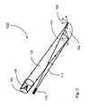
- the device 100includes a source 110, a detector 130 and an optical collecting optics 150.
- the source 110 and the detector 130define an optical path along which a beam of light travels from the source 110 to the detector 130, and the collecting optics 150 is positioned in the optical path. Further, the source 110, the detector 130 and the collecting means 150 are located in the same side of the road.
- the source 110emits a beam of light 112 that is transmitted through an exhaust plume 140 emitted from the vehicle 105 to the surface 102 of a lane 101 of the road on which the vehicle 105 is driven.
- the transmitted light 112is scattered, in a 2 ⁇ steradian hemisphere, at the surface 102 of the lane 101.
- a portion 122 of the scattered light 120 along the optical pathis collected by the concave mirror (the optical collecting optics) 150.
- the concave mirror 150delivers the portion 122 of the scattered light 120 to the detector 130 that is located at the focus of the concave mirror 150.
- the detector 130may includes a plurality of photosensors. Each photosensor generates an electrical signal responsive of the scattered light received.
- the electrical signalis indicative of the absorption of the scattered light by the exhaust plume.
- the device 100has a processor (not shown) in communication with the detector 130 to process the electrical signals from the detector 130 so as to determine components and concentrations of the exhaust plume.
- the processormay have a spectrometer.
- the focal plane of the concave mirror 150can be used to position several different detectors that image different sections of the road. One can image a strip of the road surface by using a parallel array detector.
- the light sourcesare pulse or chopped in accord with lock-in amplifiers to increase sensitivity and to differentiate light sources.
- the light sourcecan be directed to individual lanes of traffic and therefore can detect emissions of vehicles from specific lanes. Residual, low concentration exhausts from the neighboring lanes of traffic and be taken into account and deducted.
- the light sourcecan be directed to areas on the lane of traffic that would most likely target vehicles of different manufacturers that have tailpipes at different positions. Detecting the exhausts soon after it exits the tailpipe will allow detecting the highest concentrations of molecules of the exhaust before they mix with the ambient air. This will give the most precise remote sensing of the vehicle emissions.
- An examplewould be GM SUV tail pipe being positioned just after the right rear tire. Collection optics could image the right edge of the road to target the GM SUVs. A reading of the exhaust could be sensed before the rear of the vehicle passes the device, giving one a reading of the high possible concentrations.
- the devicecan measure concentration of pollutants such as hydrocarbons, CO, CO 2 , SO 2 , NH 3 and NO 2 of passing vehicles.
- the devicealso has a license recognition system and a velocity radar system to characterize the emission profile of different vehicles.
- the license recognition system and the velocity radar systemcan be those available on the market. Accordingly, the device used in the present method is much less expensive, and yet with superior performance, than the conventional devices.
- a system of remote sensing of vehicle exhaustmay comprises several devices as disclosed above and one license recognition and velocity radar system.
- the same devicecan also be used to remote sensing of emissions of a vehicle such as a heavy-duty truck that has the exhaust pile installed on its top, whereby the emitted exhaust plume is far away from the surface of the road on which the vehicle is driven.
- a bottom surface of bridge or the likecan be utilized to scatter the beam of light that transmits through the exhaust plume.
- the device 800has a source and a detector, as disclosed above, which are housed inside a device case. The device 800 is set up such that the beam of light 812 emitted from the source is directed upwards at the surface 802 of a bridge 801, instead of downwards at the lane surface of the road on which the vehicle 905 is driven.
- the beam of light 812is transmitted through the exhaust plume 840 emitted from the vehicle 805 towards the surface 802 of the bridge 801.
- the transmitted lightis then scattered at the surface 802 of the bridge 801.
- At least one portion 822 of the scattered light 820is received by the detector and processed therein so as to determine components and concentrations of the exhaust plume.
- a processor in communication with the detectormay be assembled inside the device case or outside the device case, for processing the data signals generated by the detector responsive to the scattered light.
- a Broadband Source - Halogen Light BulbIn one embodiment, a halogen light bulb such as a car headlight is used as the source.
- a collimating opticscan be utilized to collimate the beam of light emitted from the halogen light bulb and to transmit the collimated light through the exhaust plume to the surface of the lane.
- the collimating opticsincludes a first concave mirror 361 and a second concave mirror 362 positioned in relation to the broadband source 310 such that the first concave mirror 361 receives the beam of light 312 emitted from the source 310 and reflects the received light 312 to the second concave mirror 362.
- the second concave mirror 362collimates the reflected light 363 and transmits the collimated light 370 through the exhaust plume to the surface of the lane.
- the first concave mirror 361 and the second concave mirror 362define a focus 365 therebetween.
- the reflected light 363is chopped with a wheel or bell chopper 366.
- the chopper signalis fed in to a dual-phase lock-in amplifier.
- the lock-in amplifierthen amplifies the signal without adding noise.
- This broadband sourceradiates from ultraviolet to infrared light out to 5 ⁇ m. This covers strong fundamental absorption bands of CO and CO 2 as well as strong violet and ultraviolet bands of NO 2 , NO and SO 2 . Filters can be used to isolate specific bands of these molecules, along with water vapor, hydrocarbons, ammonia and others.
- a modulated halogen light sourceis strong in intensity and can be scattered over the complete lane.
- Mirrorscan be used to collect the light anywhere it is shining. Depending on the focal length and distance, these mirrors can image specific illuminated positions on to a detector. This allows different paths or position to be used to target different tailpipe positions.
- LEDscan be modulated and thus end the need for a physical chopper. They have also narrower bandwidth than the in the past. They have about the same bandwidth as filters. Therefore there is no need for filters on the detectors.
- the modulation of LEDscan be in the MHz range. This gives you more flexibility to filter out ambient noise. This noise is mainly due to thermals coming from the road surface.
- Diode LasersThe telecommunication industry as open up diode lasers to low cost.
- the telecommunication industryuses fiber optics and diode lasers to transmit large amounts of data, long distances. Because of the material of the fiber optics the average wavelength of these lasers is approximately 1.5 ⁇ m.
- the laser diodes and InGaAs detectorsare extremely inexpensive and extremely high quality because of the mass production and cost affectedness of sensitivity of the products. This allows for detection of these bands even though some are extremely weak.
- Diode laserscan be used to remote sense temperature of exhaust, because of the Boltzmann factor and the extreme narrowness of a laser line.
- the thermal distribution of rotational levelsis not simply given by the Boltzmann factor e -ElkT .
- Fig. 4shows the spectra of CO2 in the 1.5 ⁇ m region.
- the Boltzmann factorcan be seen in the higher rotational energies.
- the absorption lines at higher rotational energiesfollow the Boltzmann Factor and therefore can be used to calculate the temperature of the exhaust.
- the mixing ratio of molecules in the exhaustchanges as a vehicle warms up. A cold car pollutes more than a hot one.
- Diode lasershave an FWHM (Full Width at Half Maximum) in the range of about 6-10 MHz. This means it can sit on top of one absorption line. Different wavelength lasers can be selected to give the slope or shape of the Boltzmann factor. Then the temperature of the exhaust can be calculated. These lasers can be modulated at different frequencies. This allows the different detectors with lock-in amplifiers to be used to differentiate between the lasers illuminating the same spot.
- FWHMFull Width at Half Maximum
- the detectors usedare positioned at the focus of the collecting optics.
- the light collecting opticsincludes a Newtonian telescope, as shown in Fig. 5 .
- the Newtonian telescopeincludes a single concave mirror 550 and a reflecting plate 555 placed inside a tube 501.
- the concave mirror 550receives the beam of light 520 scattered from the surface of the lane of the road on which a vehicle is driven, and focuses it onto the plate 555.
- the plate 555directs the light along its axis 556 to the focus 557 in which the detector 530 is placed.
- the focus 557is outside the tube 501.
- the plate 555is configured to rotate around the axis 556.
- the detector 530is connected to a pre-amplifier and a lock-in amplifier.
- Array detectorscan be used to image strips of the road. This allows one to capture the entire exhaust plume and then to get absolute concentrations of the exhaust of a vehicle, irrelevant to the position or height of the tailpipe.
- each detectoris connected to a separate lock-in amplifier.
- the source 610 and the detector 630are placed on the same optical axis 655, as shown in Fig. 6 .
- the sphere mirror 650serves as the collecting optics for collecting the scattered light scattered from the surface of the lane and focusing the collected light onto the detector 630.
- the laser sourceis brought into the mirror housing with optical fiber. The laser can be outside of the housing.
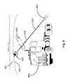
- Fig. 7shows schematically a setup of such a system in which one remote sensing device 711 is located in an accelerating zone, one 712 is located in an idling zone that is around the speed bump 703 placed on the road 701, and the other 713 is located in a decelerating zone. Additionally, a license recognition system 715 and a velocity radar system 716 are also incorporated into the remote sensing device 713. Accordingly, the measurements of the remote sensing devices 711, 712 and 713 are corresponding to the exhausts of a vehicle in the accelerating, idling and decelerating conditions, respectively.
- the present inventionrecites a method that uses a remote sensing device that uses the LIDAR technology.
- the beam of light emitted from a sourceis directed downwards, transmitting through the exhaust plume, toward the surface of a traffic lane of a road on which the vehicle is driven.
- the transmitted lightis then scattered at the surface of the traffic lane.
- a collecting opticsis used to collect the scattered light from the surface of the traffic lane.
- the collected lightis delivered to the detector for analyzing the components and concentrations of the exhaust plume.
- a detector arraycan be utilized to acquire images of the exhaust plume and the surface of the road, which would enable to unveil the whole picture of of gas pollutants in the vehicle exhaust.
Landscapes
- Physics & Mathematics (AREA)
- Chemical & Material Sciences (AREA)
- Spectroscopy & Molecular Physics (AREA)
- Combustion & Propulsion (AREA)
- Engineering & Computer Science (AREA)
- General Physics & Mathematics (AREA)
- Biochemistry (AREA)
- General Health & Medical Sciences (AREA)
- Analytical Chemistry (AREA)
- Immunology (AREA)
- Pathology (AREA)
- Life Sciences & Earth Sciences (AREA)
- Health & Medical Sciences (AREA)
- Investigating Or Analysing Materials By Optical Means (AREA)
Description
- The present invention generally relates to emission detection of vehicles, and more particularly to a method that utilizes the LIDAR technology to remotely detect emission of vehicles.
- It is known that vehicle emissions are a major contributor to air pollution. To identify vehicles that are releasing excessively polluting emissions, annually vehicle emission inspection is mandated in many countries. Accordingly, various emission inspection systems have been developed for the vehicle emission inspection. Generally, these systems are very expansive, and their operations require in a vast amount of labor and skill. Additionally, they are operated in testing stations to detect emissions of vehicles in either idling or artificially loaded conditions. Although the detection provides general baseline information regarding vehicle emissions, it is not representative of "real world' driving.
- Recently, remote emission sensing systems have been developed for detecting emissions of vehicles driven on the road. For example,
U.S. Patent Nos. 5,319,199 and5,498,872 to Stedman et al. discloses a remote sensing system in which thelight source 910 anddetector 930 are oppositely located on both sides of theroad 901, respectively, as shown inFig. 9(a) . For such an arrangement, a beam oflight 915 generated from thesource 910 passes through anexhaust plume 940 emitted from avehicle 905 driven on theroad 901, thereby carrying absorption signal associated with components and concentrations of theexhaust plume 940. Thebeam 915 is collected by thedetector 930 for analyzing the components and concentrations ofexhaust plume 940. Alternatively, as shown inFig. 9(b) , thelight source 910 anddetector 930 are located on the same side of theroad 901. And tworeflectors 950 located on the opposite side of theroad 901 are used to reflect thebeam 915 generated from thesource 910 to thedetector 930 with two passes through thevehicle exhaust plume 940, which increases the absorption signal. - However, for such remote emission sensing systems, the source, detector and reflectors are set up in both sides of the road, extra cares need being taken during the installation and maintenance. On the other hand, it is difficult to correctly associate each vehicle with its emission data when more than one vehicle is present in multiple lanes. For example, if multiple vehicles are present at the sensing location, each vehicle's exhaust plume may contribute emissions. Thus, the existing systems are not able to differentiate among several exhaust plumes.
- Also, the accuracy can depend on the height of the beam of light going across the road. The height of the tail pipe varies from vehicle to vehicle. The emission reads will vary depending on whether the beam is at the height of the tail pipe, lower or higher where the exhaust has time to dilute before detection. By looking down on to the
- Also the prior art according to
US 2002/0092988 A1 is based on such a conventional measuring approach. US 6,542, 831 B1 applies a short-range LIDAR measuring approach for measuring particles in exhaust gas of vehicles. A detector receives radiation which is backscattered by the particles in the exhaust gas to be measured. On one side of the road a laser source and the detector are deployed and on the other side a beam terminus for terminating the laser beam emitted by the laser source is deployed. The measuring approach requires that the beam terminus sufficiently reduces rear - back scatter, so that back scattering from the beam terminus does not overshine the back scattering from the particles in the exhaust gas.- Therefore, a heretofore unadressed need exists in the art to address the aforementioned deficiencies and inadequacies.
- Accordingly, it is an object to provide a method for effective remote sensing of emiossions of a vehicle driven on a road. Such a method is provided by
claim 1. Preferred embodiments are defined in the dependent claims. - According to the invention, a back scattering of light from the surface of the road on which a vehicle is driving or from the bottom of a bridge through which the vehicle is driving is used for returning the radiation, which was emitted by a light source, to the detector, to determine components and concentrations of the exhaust plume.
- In the following preferred embodiments of a device for remote sensing of emissions of a vehicle driven on a road, which can be used for measurements according to the method of the invention, are indicated.
- In one embodiment, the method uses a source for emitting a beam of light and transmitting the emitted light through an exhaust plume emitted from the vehicle to the surface of a lane of the road on which the vehicle is driven, wherein the transmitted light is scattered at the surface of the lane; a detector for receiving at least one portion of the scattered light scattered from the surface of the lane; and a processor for processing the received light therein to provide one or more spectra of the received light so as to determine components and concentrations of the exhaust plume. The source and the detector are located in the same side of the road.
- In one embodiment, the source has a halogen light source. A collimating optics is adapted for collimating the emitted light and transmitting the collimated light through the exhaust plume to the surface of the lane. In one embodiment, the collimating optics comprises a first concave mirror and a second concave mirror positioned in relation to the source such that the first concave mirror receives the beam of light emitted from the source and reflects the received light to the second concave mirror, the second concave mirror, in turn, collimates the reflected light and transmits the collimated light through the exhaust plume to the surface of the lane. The first concave mirror and the second concave mirror define a focus therebetween, and a chopper is placed on the focus.
- When the beam of light is a broadband light, one or more filters are adapted and positioned in front of the detector. Each filter has a predetermined bandwidth.
- In another one embodiment, the source comprises light emitting diodes (LEDs).
- In yet another one embodiment, the source comprises a laser. In one embodiment, the laser includes a diode laser. In the case, both the source and the detector are placed on the same optical axis.
- The method further may use a collecting optics positioned in an optical path between the source and detector for collecting the scattered light scattered from the surface of the lane and delivering the collected light to the detector, where the collecting optics has a focus on the optical path, and the detector is placed on the focus. In one embodiment, the collecting optics comprises a Newtonian telescope. In another embodiment, the collecting optics comprises a concave mirror.
- In one embodiment, the detector includes a plurality of photosensors, each photosensor generating an electrical signal responsive of the scattered light received, where the electrical signal is indicative of the absorption of the scattered light by the exhaust plume. In another embodiment, the detector comprises an array detector capable of capturing images of the exhaust plume.
- In one embodiment, the processor comprises a spectrometer.
- In one embodiment, the method uses a source for emitting a beam of light and transmitting the emitted light through an exhaust plume emitted from the vehicle to the surface of a lane of the road on which the vehicle is driven, wherein the transmitted light is scattered at the surface of the lane; a detector for receiving light and processing the received light therein to provide one or more spectra of the received light, wherein the detector and the source are located in the same side of the road and define an optical path therebetween; and a collecting optics positioned in the optical path for collecting the scattered light scattered from the surface of the lane and delivering the collected light to the detector.
- The source comprises a halogen light source, LEDs, or a laser. The collecting optics comprises a concave mirror or Newtonian telescope.
- In one embodiment, the detector comprises a plurality of photosensors, each photosensor generating an electrical signal responsive of the scattered light received, wherein the electrical signal is indicative of the absorption of the scattered light by the exhaust plume. The detector may further include a processor responsive to the electrical signals from the plurality of photosensors for determining components and concentrations of the exhaust plume.
- In another embodiment, the detector has an array detector capable of capturing images of the exhaust plume.
- In one embodiment, the method uses a license plate reader for identifying the vehicle to be detected. Further, the device may have a speed reader for detecting the speed of the vehicle so as to determine an exhaust pattern of the vehicle.
- In one embodiment, the method uses a source for emitting a beam of light and transmitting the emitted light through an exhaust plume emitted from the vehicle to a surface at which the transmitted light is scattered, and a detector for receiving at least one portion of the scattered light scattered from the surface and processing the received light therein to provide one or more spectra of the received light so as to determine components and concentrations of the exhaust plume. The surface is corresponding to the bottom surface of a bridge through which the vehicle is driven, or the surface of a lane of a road on which the vehicle is driven.
- These and other aspects of the present invention will become apparent from the following description of the preferred embodiment taken in conjunction with the following drawings, although variations and modifications therein may be effected without departing from the scope of the invention as defined by the appended claims.
- The accompanying drawings illustrate one or more embodiments of the invention and, together with the written description, serve to explain the principles of the invention. Wherever possible, the same reference numbers are used throughout the drawings to refer to the same or like elements of an embodiment, wherein:
Fig. 1 shows schematically a device for remote sensing of vehicle emission which can be used in the method of the present invention;Fig. 2 shows schematically an optical diagram of the remote sensing device which can be used in the method of the present invention;Fig. 3 shows schematically a collimating optics utilized in the remote sensing device which can be used in the method of the present invention;Fig. 4 shows the absorption lines at higher rotational energies follow the Boltzmann Factor;Fig. 5 shows schematically a collecting optics utilized in the remote sensing device which can be used in the method of the present invention;Fig. 6 shows schematically a collecting optics utilized in the remote sensing device which can be used in the method of the present invention;Fig. 7 shows schematically an application of the device of remote sensing of vehicle emission which can be used in the method of the present invention;Fig. 8 shows schematically a device for remote sensing of vehicle emission which can be used in the method of the present invention; andFig. 9 shows schematically a conventional device for remote sensing of vehicle emission.- The present invention is more particularly described in the following examples that are intended as illustrative only since numerous modifications and variations therein will be apparent to those skilled in the art. Various embodiments of the invention are now described in detail. Referring to the drawings, like numbers indicate like components throughout the views. As used in the description herein and throughout the claims that follow, the meaning of "a", "an", and "the" includes plural reference unless the context clearly dictates otherwise. Also, as used in the description herein and throughout the claims that follow, the meaning of "in" includes "in" and "on" unless the context clearly dictates otherwise. Additionally, some terms used in this specification are more specifically defined below.
- The terms used in this specification generally have their ordinary meanings in the art, within the context of the invention, and in the specific context where each term is used. Certain terms that are used to describe the invention are discussed below, or elsewhere in the specification, to provide additional guidance to the practitioner regarding the description of the invention. The use of examples anywhere in this specification, including examples of any terms discussed herein, is illustrative only, and in no way limits the scope and meaning of the invention or of any exemplified term. Likewise, the invention is not limited to various embodiments given in this specification.
- As used herein, "around", "about" or "approximately" shall generally mean within 20 percent, preferably within 10 percent, and more preferably within 5 percent of a given value or range. Numerical quantities given herein are approximate, meaning that the term "around", "about" or "approximately" can be inferred if not expressly stated.
- As used herein, the term "LIDAR" is an acronym or abbreviation of "light detection and ranging", and is an optical remote sensing technology that measures properties of scattered light to find range and/or other information of a distant target.
- As used herein, the terms "comprising," "including," "having," "containing," "involving," and the like are to be understood to be open-ended, i.e., to mean including but not limited to.
- The description will be made as to the embodiments of the present invention in conjunction with the accompanying drawings in
Figs. 1-8 . In accordance with the purposes of this invention, as embodied and broadly described herein, this invention, in one aspect, relates to a method that utilizes the LIDAR technology to detect emissions of a vehicle. The method uses a device which is a portable roadside system for detection of exhaust emissions of a vehicle having internal combustion engines and driven on a lane of a road. While the conventional emission detection devices use mirrors or retro reflectors to return a beam of light emitted from a source and transmitted through an exhaust plume of the vehicle to a detector, the invented method uses the LIDAR technology. The beam of light emitted from a source is directed downwards, passing through the exhaust plume, toward the surface of a traffic lane of a road on which the vehicle is driven. The transmitted light is then scattered at the surface of the traffic lane. The invented method collects the scattered light from the surface of the traffic lane with concave mirrors to the detector. Further, a detector array can be utilized to acquire images of the exhaust plume and the surface of the road for determining the column concentrations of gas pollutants in the exhaust plume. - Referring to
Figs. 1 and2 , and particularly toFig. 2 , adevice 100 for remote sensing of vehicle emission is shown schematically according to one example of the present disclosure. Thedevice 100 includes asource 110, adetector 130 and anoptical collecting optics 150. Thesource 110 and thedetector 130 define an optical path along which a beam of light travels from thesource 110 to thedetector 130, and the collectingoptics 150 is positioned in the optical path. Further, thesource 110, thedetector 130 and the collecting means 150 are located in the same side of the road. - In operation, the
source 110 emits a beam oflight 112 that is transmitted through anexhaust plume 140 emitted from thevehicle 105 to thesurface 102 of alane 101 of the road on which thevehicle 105 is driven. The transmittedlight 112 is scattered, in a 2π steradian hemisphere, at thesurface 102 of thelane 101. Aportion 122 of thescattered light 120 along the optical path is collected by the concave mirror (the optical collecting optics) 150. Theconcave mirror 150, in turn, delivers theportion 122 of thescattered light 120 to thedetector 130 that is located at the focus of theconcave mirror 150. Thedetector 130 may includes a plurality of photosensors. Each photosensor generates an electrical signal responsive of the scattered light received. The electrical signal is indicative of the absorption of the scattered light by the exhaust plume. Furthermore, thedevice 100 has a processor (not shown) in communication with thedetector 130 to process the electrical signals from thedetector 130 so as to determine components and concentrations of the exhaust plume. In one example, the processor may have a spectrometer. - Additionally, the focal plane of the
concave mirror 150 can be used to position several different detectors that image different sections of the road. One can image a strip of the road surface by using a parallel array detector. - Different light sources are utilized requiring different configurations and detector technologies. The light sources are pulse or chopped in accord with lock-in amplifiers to increase sensitivity and to differentiate light sources.
- The light source can be directed to individual lanes of traffic and therefore can detect emissions of vehicles from specific lanes. Residual, low concentration exhausts from the neighboring lanes of traffic and be taken into account and deducted.
- Also the light source can be directed to areas on the lane of traffic that would most likely target vehicles of different manufacturers that have tailpipes at different positions. Detecting the exhausts soon after it exits the tailpipe will allow detecting the highest concentrations of molecules of the exhaust before they mix with the ambient air. This will give the most precise remote sensing of the vehicle emissions. An example would be GM SUV tail pipe being positioned just after the right rear tire. Collection optics could image the right edge of the road to target the GM SUVs. A reading of the exhaust could be sensed before the rear of the vehicle passes the device, giving one a reading of the high possible concentrations.
- The device can measure concentration of pollutants such as hydrocarbons, CO, CO2, SO2, NH3 and NO2 of passing vehicles. The device also has a license recognition system and a velocity radar system to characterize the emission profile of different vehicles. The license recognition system and the velocity radar system can be those available on the market. Accordingly, the device used in the present method is much less expensive, and yet with superior performance, than the conventional devices. Additionally, a system of remote sensing of vehicle exhaust may comprises several devices as disclosed above and one license recognition and velocity radar system.
- Additionally, the same device can also be used to remote sensing of emissions of a vehicle such as a heavy-duty truck that has the exhaust pile installed on its top, whereby the emitted exhaust plume is far away from the surface of the road on which the vehicle is driven. In this case, a bottom surface of bridge or the like can be utilized to scatter the beam of light that transmits through the exhaust plume. As shown in
Fig, 8 , thedevice 800 has a source and a detector, as disclosed above, which are housed inside a device case. Thedevice 800 is set up such that the beam oflight 812 emitted from the source is directed upwards at thesurface 802 of abridge 801, instead of downwards at the lane surface of the road on which thevehicle 905 is driven. The beam oflight 812 is transmitted through theexhaust plume 840 emitted from thevehicle 805 towards thesurface 802 of thebridge 801. The transmitted light is then scattered at thesurface 802 of thebridge 801. At least oneportion 822 of thescattered light 820 is received by the detector and processed therein so as to determine components and concentrations of the exhaust plume. Additionally, a processor in communication with the detector may be assembled inside the device case or outside the device case, for processing the data signals generated by the detector responsive to the scattered light. - Without intent to limit the scope of the invention, exemplary devices and their related results used in the method according to the embodiments of the present invention are given below. Note that titles or subtitles may be used in the examples for convenience of a reader, which in no way should limit the scope of the invention. Moreover, certain theories are proposed and disclosed herein; however, in no way they, whether they are right or wrong, should limit the scope of the invention.
- A Broadband Source -Halogen Light Bulb: In one embodiment, a halogen light bulb such as a car headlight is used as the source. For such a broadband source, a collimating optics can be utilized to collimate the beam of light emitted from the halogen light bulb and to transmit the collimated light through the exhaust plume to the surface of the lane. As shown in
Fig. 3 , the collimating optics includes a firstconcave mirror 361 and a secondconcave mirror 362 positioned in relation to thebroadband source 310 such that the firstconcave mirror 361 receives the beam oflight 312 emitted from thesource 310 and reflects the received light 312 to the secondconcave mirror 362. The secondconcave mirror 362, in turn, collimates the reflectedlight 363 and transmits the collimated light 370 through the exhaust plume to the surface of the lane. The firstconcave mirror 361 and the secondconcave mirror 362 define afocus 365 therebetween. At thefocus 365, the reflectedlight 363 is chopped with a wheel orbell chopper 366. The chopper signal is fed in to a dual-phase lock-in amplifier. The lock-in amplifier then amplifies the signal without adding noise. - This broadband source radiates from ultraviolet to infrared light out to 5µm. This covers strong fundamental absorption bands of CO and CO2 as well as strong violet and ultraviolet bands of NO2, NO and SO2. Filters can be used to isolate specific bands of these molecules, along with water vapor, hydrocarbons, ammonia and others.
- A modulated halogen light source is strong in intensity and can be scattered over the complete lane. Mirrors can be used to collect the light anywhere it is shining. Depending on the focal length and distance, these mirrors can image specific illuminated positions on to a detector. This allows different paths or position to be used to target different tailpipe positions.
- Light Emitting Diodes (LEDs): LEDs can be modulated and thus end the need for a physical chopper. They have also narrower bandwidth than the in the past. They have about the same bandwidth as filters. Therefore there is no need for filters on the detectors. The modulation of LEDs can be in the MHz range. This gives you more flexibility to filter out ambient noise. This noise is mainly due to thermals coming from the road surface.
- Diode Lasers: The telecommunication industry as open up diode lasers to low cost. The telecommunication industry uses fiber optics and diode lasers to transmit large amounts of data, long distances. Because of the material of the fiber optics the average wavelength of these lasers is approximately 1.5µm. There are infrared absorption bands of CO2, CO, H2O, NH2 and others in this region. The laser diodes and InGaAs detectors are extremely inexpensive and extremely high quality because of the mass production and cost affectedness of sensitivity of the products. This allows for detection of these bands even though some are extremely weak.
- Diode lasers can be used to remote sense temperature of exhaust, because of the Boltzmann factor and the extreme narrowness of a laser line. The thermal distribution of rotational levels is not simply given by the Boltzmann factore-ElkT. The number of moleculesNJ in the rotational levelJ of the lowest vibrational state at the temperatureT is proportional to (G. Herzberg. Spectra of Diatomic Molecules, 2nd ed. D. Van Nostrand Co. 1950):

- This infers the higher the J value or rotational energy the more the exponential term dominates. One can then back out the temperature of the exhaust using this relationship.
Fig. 4 shows the spectra of CO2 in the 1.5 µm region. The Boltzmann factor can be seen in the higher rotational energies. The absorption lines at higher rotational energies follow the Boltzmann Factor and therefore can be used to calculate the temperature of the exhaust. - The mixing ratio of molecules in the exhaust changes as a vehicle warms up. A cold car pollutes more than a hot one. One can detect the temperature along with the concentration of gases in an exhaust plume using two or three different wavelength lasers. One can then adjust concentration expectations due to the temperature of the engine and tailpipe.
- Diode lasers have an FWHM (Full Width at Half Maximum) in the range of about 6-10 MHz. This means it can sit on top of one absorption line. Different wavelength lasers can be selected to give the slope or shape of the Boltzmann factor. Then the temperature of the exhaust can be calculated. These lasers can be modulated at different frequencies. This allows the different detectors with lock-in amplifiers to be used to differentiate between the lasers illuminating the same spot.
- According to the present invention, the detectors used are positioned at the focus of the collecting optics. In one embodiment, the light collecting optics includes a Newtonian telescope, as shown in
Fig. 5 . The Newtonian telescope includes a singleconcave mirror 550 and a reflectingplate 555 placed inside atube 501. Theconcave mirror 550 receives the beam oflight 520 scattered from the surface of the lane of the road on which a vehicle is driven, and focuses it onto theplate 555. Theplate 555 directs the light along itsaxis 556 to thefocus 557 in which thedetector 530 is placed. Thefocus 557 is outside thetube 501. Theplate 555 is configured to rotate around theaxis 556. Thedetector 530 is connected to a pre-amplifier and a lock-in amplifier. - Different sources need different detector systems. For a broadband light source, one or more filters are positioned in front of the detectors. Array detectors can be used to image strips of the road. This allows one to capture the entire exhaust plume and then to get absolute concentrations of the exhaust of a vehicle, irrelevant to the position or height of the tailpipe.
- For an LED source, no filter is needed, although the LED source is a broadband source. An LED of different wavelengths has a different modulation frequency and therefore, each detector is connected to a separate lock-in amplifier.
- For a diode laser source, the
source 610 and thedetector 630 are placed on the sameoptical axis 655, as shown inFig. 6 . Thesphere mirror 650 serves as the collecting optics for collecting the scattered light scattered from the surface of the lane and focusing the collected light onto thedetector 630. The laser source is brought into the mirror housing with optical fiber. The laser can be outside of the housing. - One of the main liabilities of remote sensing of car exhaust is that the mixing ratio changes depending on whether the vehicle/car is idling, accelerating or decelerating. One embodiment uses, three remote sensing devices are used to detect the exhaust of the vehicle during idling, accelerating or decelerating.
Fig. 7 shows schematically a setup of such a system in which oneremote sensing device 711 is located in an accelerating zone, one 712 is located in an idling zone that is around thespeed bump 703 placed on theroad 701, and the other 713 is located in a decelerating zone. Additionally, alicense recognition system 715 and avelocity radar system 716 are also incorporated into theremote sensing device 713. Accordingly, the measurements of theremote sensing devices - In sum, the present invention, among other things, recites a method that uses a remote sensing device that uses the LIDAR technology. The beam of light emitted from a source is directed downwards, transmitting through the exhaust plume, toward the surface of a traffic lane of a road on which the vehicle is driven. The transmitted light is then scattered at the surface of the traffic lane. A collecting optics is used to collect the scattered light from the surface of the traffic lane. The collected light is delivered to the detector for analyzing the components and concentrations of the exhaust plume. Additionally, according to the present invention, a detector array can be utilized to acquire images of the exhaust plume and the surface of the road, which would enable to unveil the whole picture of of gas pollutants in the vehicle exhaust.
- The foregoing description of the exemplary embodiments of the invention has been presented only for the purposes of illustration and description and is not intended to be exhaustive or to limit the invention to the precise forms disclosed. Many modifications and variations are possible in light of the above teaching.
- The embodiments were chosen and described in order to explain the principles of the invention and their practical application so as to activate others skilled in the art to utilize the invention and various embodiments and with various modifications as are suited to the particular use contemplated. Alternative embodiments will become apparent to those skilled in the art to which the present invention pertains without departing from its scope as defined by the appended claims. Accordingly, the scope of the present invention is defined by the appended claims rather than the foregoing description and the exemplary embodiments described therein.

Claims (15)
- Method for remote sensing of emissions of a vehicle driven on a road, comprising:A) deploying a source (110, 310; 610) for emitting a beam of light and a detector (130; 530; 630) for detecting light in the same side of the road;B) transmitting the beam of light emitted by said source (110, 310; 610) through an exhaust plume emitted from the vehicle to a surface at which the transmitted light is scattered, wherein said surface is a bottom (802) of a bridge through which the vehicle is driven or is the surface (102) of a lane of the road on which the vehicle is driven;C) receiving, by means of said detector, at least one portion of the scattered light scattered from the surface and processing the received light therein to provide one or more spectra of the received light so as to determine components and concentrations of the exhaust plume.
- The method according to claim 1, wherein a device (100; 711; 712; 716; 800) for remote sensing of emissions of a vehicle driven on a road is used, which has a processor for processing the received light to provide said one or more spectra of the received light so as to determine said components and concentrations of the exhaust plume.
- The method of claim 2, wherein the source comprises a broadband light source (310) or light emitting diodes (LEDs) or a laser (610).
- The method of claim 2, wherein the device further comprises a collimating optics (361, 362) for collimating the light emitted by the broadband light (310) source and transmitting the collimated light through the exhaust plume to the surface of the lane.
- The method of claim 4, wherein the collimating optics comprises a first concave mirror (361) and a second concave mirror (362) positioned in relation to the source such that the first concave mirror receives the beam of light emitted from the source and reflects the received light to the second concave mirror, the second concave mirror, in turn, collimates the reflected light and transmits the collimated light through the exhaust plume to the surface of the lane.
- The method of claim 5, wherein the first concave mirror (361) and the second concave mirror (362) define a focus (365) therebetween, and a chopper (366) is placed on the focus.
- The method of claim 3, wherein, when the source comprises said broad band light source (310), the device further comprises one or more filters positioned in relation to the detector, each filter having a predetermined bandwidth.
- The method of claim 3, wherein the laser comprises a diode laser (610), and wherein both the source (610) and the detector (630) are placed on the same optical axis.
- The method of claim 2, wherein the device further comprises a collecting optics (150; 550; 535; 650) positioned in an optical path between the source and detector for collecting the scattered light scattered from the surface of the lane and delivering the collected light to the detector, wherein the collecting optics has a focus on the optical path, and wherein the detector is placed on the focus.
- The method of claim 2, wherein the processor comprises a spectrometer.
- The method of claim 1, wherein the detector (110; 310; 610) and the source (130; 530; 630), which are located in the same side of the road, define an optical path therebetween; and wherein a collecting optics (150; 550, 555; 650) is positioned in the optical path for collecting the scattered light scattered from the surface of the lane and delivering the collected light to the detector.
- The method of claim 9 or 11, wherein the collecting optics comprises a concave mirror (150; 650) or Newtonian telescope (501, 550, 555).
- The method of claim 2 or 11, wherein the detector comprises a plurality of photosensors, each photosensor generating an electrical signal responsive of the scattered light received, wherein the electrical signal is indicative of the absorption of the scattered light by the exhaust plume.
- The method of claim 2 or 11, wherein the detector comprises a detector array capable of capturing images of the exhaust plume and the surface of the road.
- The method of claim 1, further comprising at least one of detecting the speed of the vehicle using a speed sensor so as to determine an exhaust pattern of the vehicle and identifying the vehicle to be detected using a license plate reader.
Applications Claiming Priority (2)
| Application Number | Priority Date | Filing Date | Title |
|---|---|---|---|
| US12/493,634US8134711B2 (en) | 2009-06-29 | 2009-06-29 | Device for remote sensing of vehicle emission |
| PCT/US2010/040330WO2011011166A1 (en) | 2009-06-29 | 2010-06-29 | Device for remote sensing of vehicle emission |
Publications (3)
| Publication Number | Publication Date |
|---|---|
| EP2449361A1 EP2449361A1 (en) | 2012-05-09 |
| EP2449361A4 EP2449361A4 (en) | 2012-11-14 |
| EP2449361B1true EP2449361B1 (en) | 2015-09-09 |
Family
ID=43380364
Family Applications (1)
| Application Number | Title | Priority Date | Filing Date |
|---|---|---|---|
| EP10802627.9AActiveEP2449361B1 (en) | 2009-06-29 | 2010-06-29 | Method for remote sensing of vehicle emission |
Country Status (6)
| Country | Link |
|---|---|
| US (1) | US8134711B2 (en) |
| EP (1) | EP2449361B1 (en) |
| DK (1) | DK2449361T3 (en) |
| ES (1) | ES2553396T3 (en) |
| PT (1) | PT2449361E (en) |
| WO (1) | WO2011011166A1 (en) |
Cited By (1)
| Publication number | Priority date | Publication date | Assignee | Title |
|---|---|---|---|---|
| CN106529608A (en)* | 2016-12-31 | 2017-03-22 | 中国科学技术大学 | Comprehensive stationing system for exhaust gas remote-measuring equipment of motor vehicle |
Families Citing this family (14)
| Publication number | Priority date | Publication date | Assignee | Title |
|---|---|---|---|---|
| US8885035B2 (en)* | 2009-06-16 | 2014-11-11 | Lester F. Ludwig | Electronic imaging flow-microscope for environmental remote sensing, bioreactor process monitoring, and optical microscopic tomography |
| US9594239B1 (en) | 2009-06-16 | 2017-03-14 | Lester F. Ludwig | Optical tomography for microscopy, cell cytometry, microplate array instrumentation, crystallography, and other applications |
| US9228938B2 (en)* | 2009-06-29 | 2016-01-05 | Hager Environmental And Atmospheric Technologies, Llc | Method and device for remote sensing of amount of ingredients and temperature of gases |
| JP5453679B2 (en)* | 2009-10-02 | 2014-03-26 | 株式会社Sumco | Silica glass crucible manufacturing apparatus and silica glass crucible manufacturing method |
| WO2012170093A2 (en)* | 2011-03-25 | 2012-12-13 | Exxonmobil Upstream Research Company | Autonomous detection of chemical plumes |
| US8818609B1 (en) | 2012-11-15 | 2014-08-26 | Google Inc. | Using geometric features and history information to detect features such as car exhaust in point maps |
| US9501827B2 (en) | 2014-06-23 | 2016-11-22 | Exxonmobil Upstream Research Company | Methods and systems for detecting a chemical species |
| US9471969B2 (en) | 2014-06-23 | 2016-10-18 | Exxonmobil Upstream Research Company | Methods for differential image quality enhancement for a multiple detector system, systems and use thereof |
| US9442011B2 (en) | 2014-06-23 | 2016-09-13 | Exxonmobil Upstream Research Company | Methods for calibrating a multiple detector system |
| EP3158321A1 (en) | 2014-06-23 | 2017-04-26 | Exxonmobil Upstream Research Company | Systems for detecting a chemical species and use thereof |
| CN106885786A (en)* | 2017-04-07 | 2017-06-23 | 北京星空永恒科技有限公司 | Telemetering motor vehicle tail system |
| CN108414469B (en)* | 2018-03-27 | 2023-10-27 | 安徽中科华仪科技有限公司 | TDLAS (tunable diode laser absorption Spectroscopy) scanning-based transceiver integrated motor vehicle tail gas remote sensing measurement device and method |
| US12248945B2 (en) | 2021-09-15 | 2025-03-11 | U.S. Government, As Represented By The Administrator Of The U.S. Environmental Protection Agency | System and method for quantifying source and component emission rates from a body in a flow field |
| CN114252306B (en)* | 2021-12-24 | 2024-04-26 | 安徽庆宇光电科技有限公司 | Motor vehicle tail gas collecting device for remote sensing detection and detection method thereof |
Family Cites Families (23)
| Publication number | Priority date | Publication date | Assignee | Title |
|---|---|---|---|---|
| US4489239A (en) | 1982-09-24 | 1984-12-18 | The United States Of America As Represented By The Administrator Of The National Aeronautics And Space Administration | Portable remote laser sensor for methane leak detection |
| US4924095A (en) | 1987-06-02 | 1990-05-08 | West Lodge Research | Remote gas analyzer for motor vehicle exhaust emissions surveillance |
| US5845639A (en) | 1990-08-10 | 1998-12-08 | Board Of Regents Of The University Of Washington | Optical imaging methods |
| US5489777A (en) | 1990-12-26 | 1996-02-06 | Denver Seminary | Apparatus for remote analysis of vehicle emissions using reflective thermography |
| US5210702A (en) | 1990-12-26 | 1993-05-11 | Colorado Seminary | Apparatus for remote analysis of vehicle emissions |
| US5401967A (en) | 1990-12-26 | 1995-03-28 | Colorado Seminary Dba University Of Denver | Apparatus for remote analysis of vehicle emissions |
| US5252828A (en)* | 1992-04-07 | 1993-10-12 | Hughes Aircraft Company | Mobile exhaust tracking system |
| US5637873A (en)* | 1995-06-07 | 1997-06-10 | The Boeing Company | Directional reflectometer for measuring optical bidirectional reflectance |
| US5767519A (en)* | 1996-03-01 | 1998-06-16 | The Aerospace Corporation | Ambient-normalized differential absorption lidar system and method |
| US6064488A (en) | 1997-06-06 | 2000-05-16 | Monitor Labs, Inc. | Method and apparatus for in situ gas concentration measurement |
| ES2258858T3 (en) | 1998-10-30 | 2006-09-01 | Envirotest Systems, Inc. | REMOTE DETECTOR FOR MULTIPLE RAILS. |
| US6455851B1 (en) | 2000-03-28 | 2002-09-24 | Air Instruments And Measurement, Inc. | Spectroscopic remote sensing exhaust emission monitoring system |
| FI114572B (en) | 2001-04-09 | 2004-11-15 | Valtion Teknillinen | Procedure and measurement system for determining and controlling exhaust emissions |
| US6542831B1 (en) | 2001-04-18 | 2003-04-01 | Desert Research Institute | Vehicle particulate sensor system |
| US20030089854A1 (en)* | 2001-11-09 | 2003-05-15 | Shifflett Peter S. | Apparatus and method for remotely sensing hydrocarbons and other pollutants in vehicle emissions |
| US7391557B1 (en)* | 2003-03-28 | 2008-06-24 | Applied Photonics Worldwide, Inc. | Mobile terawatt femtosecond laser system (MTFLS) for long range spectral sensing and identification of bioaerosols and chemical agents in the atmosphere |
| US20060173355A1 (en) | 2003-04-17 | 2006-08-03 | Alfano Robert R | Detecting human cancer through spectral optical imaging using key water absorption wavelengths |
| US7491943B2 (en) | 2005-01-13 | 2009-02-17 | Whitehead Institute For Biomedical Research | Method and apparatus for UV imaging |
| US7375814B2 (en) | 2005-03-11 | 2008-05-20 | Sandia Corporation | Natural gas leak mapper |
| US7544943B2 (en) | 2006-01-18 | 2009-06-09 | Mutual Sky Technology Limited | Method and system for remote exhaust emission measurement |
| CN103823051B (en) | 2008-03-21 | 2015-11-18 | 艾博特健康公司 | Utilize the intrinsic pigmentation of the haemoglobin contained in red blood cell to determine the method and apparatus of the red cell index of blood sample |
| US7930931B2 (en)* | 2008-05-02 | 2011-04-26 | Environmental Systems Products Holdings Inc. | System and method for quantifying the presence of components in the exhaust of commercial and/or heavy-duty vehicles |
| EP2338044A2 (en) | 2008-09-02 | 2011-06-29 | Technion Research and Development Foundation, Ltd. | Method and apparatus for sensing the nature of a gaseous composition, particularly vehicular emissions |
- 2009
- 2009-06-29USUS12/493,634patent/US8134711B2/enactiveActive
- 2010
- 2010-06-29DKDK10802627.9Tpatent/DK2449361T3/enactive
- 2010-06-29ESES10802627.9Tpatent/ES2553396T3/enactiveActive
- 2010-06-29WOPCT/US2010/040330patent/WO2011011166A1/enactiveApplication Filing
- 2010-06-29EPEP10802627.9Apatent/EP2449361B1/enactiveActive
- 2010-06-29PTPT108026279Tpatent/PT2449361E/enunknown
Cited By (2)
| Publication number | Priority date | Publication date | Assignee | Title |
|---|---|---|---|---|
| CN106529608A (en)* | 2016-12-31 | 2017-03-22 | 中国科学技术大学 | Comprehensive stationing system for exhaust gas remote-measuring equipment of motor vehicle |
| CN106529608B (en)* | 2016-12-31 | 2019-06-11 | 中国科学技术大学 | A comprehensive distribution system for vehicle exhaust telemetry equipment |
Also Published As
| Publication number | Publication date |
|---|---|
| US8134711B2 (en) | 2012-03-13 |
| ES2553396T3 (en) | 2015-12-09 |
| US20100328660A1 (en) | 2010-12-30 |
| WO2011011166A1 (en) | 2011-01-27 |
| EP2449361A1 (en) | 2012-05-09 |
| EP2449361A4 (en) | 2012-11-14 |
| PT2449361E (en) | 2015-11-30 |
| DK2449361T3 (en) | 2015-12-21 |
Similar Documents
| Publication | Publication Date | Title |
|---|---|---|
| EP2449361B1 (en) | Method for remote sensing of vehicle emission | |
| US8838396B2 (en) | Remote vehicle emissions sensing system and method for differentiating water from hydrocarbons | |
| JP4124731B2 (en) | Exhaust opacity measuring device | |
| US20110038507A1 (en) | Device and Method for Quantification of Gases in Plumes by Remote Sensing | |
| US6744516B2 (en) | Optical path structure for open path emissions sensing | |
| US9228938B2 (en) | Method and device for remote sensing of amount of ingredients and temperature of gases | |
| Wang et al. | A potential remote sensor of CO in vehicle exhausts using 2.3 µmdiode lasers | |
| EP2715307B1 (en) | System and method for quantifying the presence of components in vehicle exhaust | |
| KR101518968B1 (en) | Real time Measurement Device in the Exhaust gas of the Motor Vehicle on the Move | |
| US8654335B2 (en) | Method and device for quantification of gases in plumes by remote sensing | |
| EP2338044A2 (en) | Method and apparatus for sensing the nature of a gaseous composition, particularly vehicular emissions | |
| CN210155029U (en) | Full laser motor vehicle exhaust remote sensing detecting system | |
| CN111855617A (en) | Motor vehicle exhaust remote sensing detection device based on laser multi-dimensional space scanning and detection method thereof | |
| EP3702757B1 (en) | Measuring system of pollutants emitted by motor vehicles on roads | |
| EP2588847B1 (en) | Device and method for quantification of gases in plumes by remote sensing | |
| US20060064255A1 (en) | Remote vehicle emission sensing device with single detector | |
| KR102293020B1 (en) | Exhaust gas real-time measurement device of a moving vehicle equipped with a soot correction means | |
| CN102128772A (en) | Device for determining particle size and/or particle concentration of gas flow with particles, and method thereof | |
| KR20210098471A (en) | A method for detecting particles or aerosols in a flowing fluid, a computer program and an electrical storage medium | |
| US20240295492A1 (en) | Device and method for determining a concentration of a material in a measurement volume | |
| WO2012002979A1 (en) | Device and method for quantification of gases in plumes by remote sensing | |
| CN109211826A (en) | A kind of light-dividing device and across wave band vehicular emission remote sensing instrument | |
| EP3105567B1 (en) | Method and device for remote sensing of amount of ingredients and temperature of gases | |
| EP2926118B1 (en) | Method and device for quantification of gases in plumes by remote sensing | |
| KR102208064B1 (en) | Improved real-time measurement device for vehicle exhaust gas |
Legal Events
| Date | Code | Title | Description |
|---|---|---|---|
| PUAI | Public reference made under article 153(3) epc to a published international application that has entered the european phase | Free format text:ORIGINAL CODE: 0009012 | |
| 17P | Request for examination filed | Effective date:20111213 | |
| AK | Designated contracting states | Kind code of ref document:A1 Designated state(s):AL AT BE BG CH CY CZ DE DK EE ES FI FR GB GR HR HU IE IS IT LI LT LU LV MC MK MT NL NO PL PT RO SE SI SK SM TR | |
| DAX | Request for extension of the european patent (deleted) | ||
| A4 | Supplementary search report drawn up and despatched | Effective date:20121017 | |
| RIC1 | Information provided on ipc code assigned before grant | Ipc:G01M 15/10 20060101ALI20121011BHEP Ipc:G01N 21/35 20060101AFI20121011BHEP Ipc:G01N 33/00 20060101ALI20121011BHEP | |
| REG | Reference to a national code | Ref country code:DE Ref legal event code:R079 Ref document number:602010027459 Country of ref document:DE Free format text:PREVIOUS MAIN CLASS: G01N0021000000 Ipc:G01N0021350000 | |
| RIC1 | Information provided on ipc code assigned before grant | Ipc:G01N 21/35 20140101AFI20141215BHEP Ipc:G01N 21/31 20060101ALI20141215BHEP Ipc:G01M 15/10 20060101ALI20141215BHEP Ipc:G01N 21/3504 20140101ALI20141215BHEP | |
| GRAP | Despatch of communication of intention to grant a patent | Free format text:ORIGINAL CODE: EPIDOSNIGR1 | |
| INTG | Intention to grant announced | Effective date:20150123 | |
| GRAS | Grant fee paid | Free format text:ORIGINAL CODE: EPIDOSNIGR3 | |
| GRAA | (expected) grant | Free format text:ORIGINAL CODE: 0009210 | |
| AK | Designated contracting states | Kind code of ref document:B1 Designated state(s):AL AT BE BG CH CY CZ DE DK EE ES FI FR GB GR HR HU IE IS IT LI LT LU LV MC MK MT NL NO PL PT RO SE SI SK SM TR | |
| REG | Reference to a national code | Ref country code:GB Ref legal event code:FG4D | |
| REG | Reference to a national code | Ref country code:AT Ref legal event code:REF Ref document number:748528 Country of ref document:AT Kind code of ref document:T Effective date:20150915 Ref country code:CH Ref legal event code:EP | |
| REG | Reference to a national code | Ref country code:IE Ref legal event code:FG4D | |
| REG | Reference to a national code | Ref country code:DE Ref legal event code:R096 Ref document number:602010027459 Country of ref document:DE | |
| REG | Reference to a national code | Ref country code:PT Ref legal event code:SC4A Free format text:AVAILABILITY OF NATIONAL TRANSLATION Effective date:20151117 | |
| REG | Reference to a national code | Ref country code:RO Ref legal event code:EPE | |
| REG | Reference to a national code | Ref country code:ES Ref legal event code:FG2A Ref document number:2553396 Country of ref document:ES Kind code of ref document:T3 Effective date:20151209 | |
| REG | Reference to a national code | Ref country code:DK Ref legal event code:T3 Effective date:20151215 | |
| REG | Reference to a national code | Ref country code:SE Ref legal event code:TRGR | |
| PG25 | Lapsed in a contracting state [announced via postgrant information from national office to epo] | Ref country code:LT Free format text:LAPSE BECAUSE OF FAILURE TO SUBMIT A TRANSLATION OF THE DESCRIPTION OR TO PAY THE FEE WITHIN THE PRESCRIBED TIME-LIMIT Effective date:20150909 Ref country code:NO Free format text:LAPSE BECAUSE OF FAILURE TO SUBMIT A TRANSLATION OF THE DESCRIPTION OR TO PAY THE FEE WITHIN THE PRESCRIBED TIME-LIMIT Effective date:20151209 Ref country code:GR Free format text:LAPSE BECAUSE OF FAILURE TO SUBMIT A TRANSLATION OF THE DESCRIPTION OR TO PAY THE FEE WITHIN THE PRESCRIBED TIME-LIMIT Effective date:20151210 Ref country code:LV Free format text:LAPSE BECAUSE OF FAILURE TO SUBMIT A TRANSLATION OF THE DESCRIPTION OR TO PAY THE FEE WITHIN THE PRESCRIBED TIME-LIMIT Effective date:20150909 | |
| REG | Reference to a national code | Ref country code:LT Ref legal event code:MG4D Ref country code:NL Ref legal event code:FP | |
| PG25 | Lapsed in a contracting state [announced via postgrant information from national office to epo] | Ref country code:HR Free format text:LAPSE BECAUSE OF FAILURE TO SUBMIT A TRANSLATION OF THE DESCRIPTION OR TO PAY THE FEE WITHIN THE PRESCRIBED TIME-LIMIT Effective date:20150909 | |
| PG25 | Lapsed in a contracting state [announced via postgrant information from national office to epo] | Ref country code:IS Free format text:LAPSE BECAUSE OF FAILURE TO SUBMIT A TRANSLATION OF THE DESCRIPTION OR TO PAY THE FEE WITHIN THE PRESCRIBED TIME-LIMIT Effective date:20160109 Ref country code:EE Free format text:LAPSE BECAUSE OF FAILURE TO SUBMIT A TRANSLATION OF THE DESCRIPTION OR TO PAY THE FEE WITHIN THE PRESCRIBED TIME-LIMIT Effective date:20150909 Ref country code:SK Free format text:LAPSE BECAUSE OF FAILURE TO SUBMIT A TRANSLATION OF THE DESCRIPTION OR TO PAY THE FEE WITHIN THE PRESCRIBED TIME-LIMIT Effective date:20150909 | |
| PG25 | Lapsed in a contracting state [announced via postgrant information from national office to epo] | Ref country code:PL Free format text:LAPSE BECAUSE OF FAILURE TO SUBMIT A TRANSLATION OF THE DESCRIPTION OR TO PAY THE FEE WITHIN THE PRESCRIBED TIME-LIMIT Effective date:20150909 | |
| REG | Reference to a national code | Ref country code:DE Ref legal event code:R097 Ref document number:602010027459 Country of ref document:DE | |
| REG | Reference to a national code | Ref country code:FR Ref legal event code:PLFP Year of fee payment:7 | |
| PLBE | No opposition filed within time limit | Free format text:ORIGINAL CODE: 0009261 | |
| STAA | Information on the status of an ep patent application or granted ep patent | Free format text:STATUS: NO OPPOSITION FILED WITHIN TIME LIMIT | |
| 26N | No opposition filed | Effective date:20160610 | |
| PG25 | Lapsed in a contracting state [announced via postgrant information from national office to epo] | Ref country code:SI Free format text:LAPSE BECAUSE OF FAILURE TO SUBMIT A TRANSLATION OF THE DESCRIPTION OR TO PAY THE FEE WITHIN THE PRESCRIBED TIME-LIMIT Effective date:20150909 | |
| PG25 | Lapsed in a contracting state [announced via postgrant information from national office to epo] | Ref country code:MC Free format text:LAPSE BECAUSE OF FAILURE TO SUBMIT A TRANSLATION OF THE DESCRIPTION OR TO PAY THE FEE WITHIN THE PRESCRIBED TIME-LIMIT Effective date:20150909 | |
| REG | Reference to a national code | Ref country code:FR Ref legal event code:PLFP Year of fee payment:8 | |
| REG | Reference to a national code | Ref country code:AT Ref legal event code:UEP Ref document number:748528 Country of ref document:AT Kind code of ref document:T Effective date:20150909 | |
| PG25 | Lapsed in a contracting state [announced via postgrant information from national office to epo] | Ref country code:CY Free format text:LAPSE BECAUSE OF FAILURE TO SUBMIT A TRANSLATION OF THE DESCRIPTION OR TO PAY THE FEE WITHIN THE PRESCRIBED TIME-LIMIT Effective date:20150909 Ref country code:HU Free format text:LAPSE BECAUSE OF FAILURE TO SUBMIT A TRANSLATION OF THE DESCRIPTION OR TO PAY THE FEE WITHIN THE PRESCRIBED TIME-LIMIT; INVALID AB INITIO Effective date:20100629 Ref country code:SM Free format text:LAPSE BECAUSE OF FAILURE TO SUBMIT A TRANSLATION OF THE DESCRIPTION OR TO PAY THE FEE WITHIN THE PRESCRIBED TIME-LIMIT Effective date:20150909 | |
| PG25 | Lapsed in a contracting state [announced via postgrant information from national office to epo] | Ref country code:MK Free format text:LAPSE BECAUSE OF FAILURE TO SUBMIT A TRANSLATION OF THE DESCRIPTION OR TO PAY THE FEE WITHIN THE PRESCRIBED TIME-LIMIT Effective date:20150909 Ref country code:LU Free format text:LAPSE BECAUSE OF NON-PAYMENT OF DUE FEES Effective date:20160629 Ref country code:TR Free format text:LAPSE BECAUSE OF FAILURE TO SUBMIT A TRANSLATION OF THE DESCRIPTION OR TO PAY THE FEE WITHIN THE PRESCRIBED TIME-LIMIT Effective date:20150909 Ref country code:MT Free format text:LAPSE BECAUSE OF NON-PAYMENT OF DUE FEES Effective date:20160630 | |
| REG | Reference to a national code | Ref country code:FR Ref legal event code:PLFP Year of fee payment:9 | |
| PG25 | Lapsed in a contracting state [announced via postgrant information from national office to epo] | Ref country code:BG Free format text:LAPSE BECAUSE OF FAILURE TO SUBMIT A TRANSLATION OF THE DESCRIPTION OR TO PAY THE FEE WITHIN THE PRESCRIBED TIME-LIMIT Effective date:20150909 | |
| PG25 | Lapsed in a contracting state [announced via postgrant information from national office to epo] | Ref country code:AL Free format text:LAPSE BECAUSE OF FAILURE TO SUBMIT A TRANSLATION OF THE DESCRIPTION OR TO PAY THE FEE WITHIN THE PRESCRIBED TIME-LIMIT Effective date:20150909 | |
| REG | Reference to a national code | Ref country code:DE Ref legal event code:R081 Ref document number:602010027459 Country of ref document:DE Owner name:HAGER ENVIRONMENTAL AND ATMOSPHERIC TECHNOLOGI, US Free format text:FORMER OWNER: HAGER, J. STEWART, KNOXVILLE, TENN., US | |
| REG | Reference to a national code | Ref country code:CH Ref legal event code:NV Representative=s name:DENNEMEYER AG, CH Ref country code:CH Ref legal event code:PUE Owner name:HAGER, J. STEWART, US Free format text:FORMER OWNER: HAGER, J. STEWART, US | |
| REG | Reference to a national code | Ref country code:ES Ref legal event code:PC2A Owner name:HAGER ENVIRONMENTAL AND ATMOSPHERIC TECHNOLOGIES, LLC Effective date:20200214 | |
| REG | Reference to a national code | Ref country code:FI Ref legal event code:PCE Owner name:HAGER ENVIRONMENTAL AND ATMOSPHERIC TECHNOLOGIES, LLC | |
| REG | Reference to a national code | Ref country code:GB Ref legal event code:732E Free format text:REGISTERED BETWEEN 20200305 AND 20200311 | |
| REG | Reference to a national code | Ref country code:BE Ref legal event code:PD Owner name:HAGER ENVIRONMENTAL AND ATMOSPHERIC TECHNOLOGIES, LLC; US Free format text:DETAILS ASSIGNMENT: CHANGE OF OWNER(S), CESSION; FORMER OWNER NAME: HAGER, J. STEWART Effective date:20200309 | |
| REG | Reference to a national code | Ref country code:NL Ref legal event code:PD Owner name:HAGER ENVIRONMENTAL AND ATMOSPHERIC TECHNOLOGIES, LLC; US Free format text:DETAILS ASSIGNMENT: CHANGE OF OWNER(S), ASSIGNMENT; FORMER OWNER NAME: HAGER, J. STEWART Effective date:20200225 | |
| REG | Reference to a national code | Ref country code:AT Ref legal event code:PC Ref document number:748528 Country of ref document:AT Kind code of ref document:T Owner name:HAGER ENVIRONMENTAL AND ATMOSPHERIC TECHNOLOGI, US Effective date:20200626 | |
| P01 | Opt-out of the competence of the unified patent court (upc) registered | Effective date:20230525 | |
| PGFP | Annual fee paid to national office [announced via postgrant information from national office to epo] | Ref country code:IT Payment date:20240619 Year of fee payment:15 | |
| PGFP | Annual fee paid to national office [announced via postgrant information from national office to epo] | Ref country code:CH Payment date:20240704 Year of fee payment:15 | |
| REG | Reference to a national code | Ref country code:DE Ref legal event code:R082 Ref document number:602010027459 Country of ref document:DE Representative=s name:DENNEMEYER & ASSOCIATES RECHTSANWALTSGESELLSCH, DE | |
| PGFP | Annual fee paid to national office [announced via postgrant information from national office to epo] | Ref country code:FI Payment date:20250625 Year of fee payment:16 | |
| PGFP | Annual fee paid to national office [announced via postgrant information from national office to epo] | Ref country code:DE Payment date:20250627 Year of fee payment:16 | |
| PGFP | Annual fee paid to national office [announced via postgrant information from national office to epo] | Ref country code:GB Payment date:20250627 Year of fee payment:16 Ref country code:DK Payment date:20250625 Year of fee payment:16 | |
| PGFP | Annual fee paid to national office [announced via postgrant information from national office to epo] | Ref country code:NL Payment date:20250626 Year of fee payment:16 Ref country code:BE Payment date:20250627 Year of fee payment:16 | |
| PGFP | Annual fee paid to national office [announced via postgrant information from national office to epo] | Ref country code:PT Payment date:20250603 Year of fee payment:16 | |
| PGFP | Annual fee paid to national office [announced via postgrant information from national office to epo] | Ref country code:FR Payment date:20250625 Year of fee payment:16 | |
| PGFP | Annual fee paid to national office [announced via postgrant information from national office to epo] | Ref country code:AT Payment date:20250603 Year of fee payment:16 Ref country code:RO Payment date:20250605 Year of fee payment:16 | |
| PGFP | Annual fee paid to national office [announced via postgrant information from national office to epo] | Ref country code:CZ Payment date:20250609 Year of fee payment:16 | |
| PGFP | Annual fee paid to national office [announced via postgrant information from national office to epo] | Ref country code:IE Payment date:20250627 Year of fee payment:16 | |
| PGFP | Annual fee paid to national office [announced via postgrant information from national office to epo] | Ref country code:SE Payment date:20250627 Year of fee payment:16 | |
| PGFP | Annual fee paid to national office [announced via postgrant information from national office to epo] | Ref country code:ES Payment date:20250701 Year of fee payment:16 |