EP2449129B1 - Methods of determining the presence and/or concentration of an analyte in a sample - Google Patents
Methods of determining the presence and/or concentration of an analyte in a sampleDownload PDFInfo
- Publication number
- EP2449129B1 EP2449129B1EP10794686.5AEP10794686AEP2449129B1EP 2449129 B1EP2449129 B1EP 2449129B1EP 10794686 AEP10794686 AEP 10794686AEP 2449129 B1EP2449129 B1EP 2449129B1
- Authority
- EP
- European Patent Office
- Prior art keywords
- analyte
- receptor
- indicator
- citrate
- complex
- Prior art date
- Legal status (The legal status is an assumption and is not a legal conclusion. Google has not performed a legal analysis and makes no representation as to the accuracy of the status listed.)
- Not-in-force
Links
- 239000012491analyteSubstances0.000titleclaimsdescription68
- 238000000034methodMethods0.000titleclaimsdescription46
- KRKNYBCHXYNGOX-UHFFFAOYSA-KCitrateChemical compound[O-]C(=O)CC(O)(CC([O-])=O)C([O-])=OKRKNYBCHXYNGOX-UHFFFAOYSA-K0.000claimsdescription58
- 229910019142PO4Inorganic materials0.000claimsdescription27
- 239000010452phosphateSubstances0.000claimsdescription26
- NBIIXXVUZAFLBC-UHFFFAOYSA-KphosphateChemical compound[O-]P([O-])([O-])=ONBIIXXVUZAFLBC-UHFFFAOYSA-K0.000claimsdescription23
- OYPRJOBELJOOCE-UHFFFAOYSA-NCalciumChemical compound[Ca]OYPRJOBELJOOCE-UHFFFAOYSA-N0.000claimsdescription22
- 239000011575calciumSubstances0.000claimsdescription22
- 229910052791calciumInorganic materials0.000claimsdescription22
- 239000012530fluidSubstances0.000claimsdescription18
- 210000004369bloodAnatomy0.000claimsdescription16
- 239000008280bloodSubstances0.000claimsdescription16
- 238000012544monitoring processMethods0.000claimsdescription13
- 238000011088calibration curveMethods0.000claimsdescription11
- 238000004401flow injection analysisMethods0.000claimsdescription11
- 239000011777magnesiumSubstances0.000claimsdescription11
- PWIGYBONXWGOQE-UHFFFAOYSA-Nalizarin complexoneChemical compoundO=C1C2=CC=CC=C2C(=O)C2=C1C=C(CN(CC(O)=O)CC(=O)O)C(O)=C2OPWIGYBONXWGOQE-UHFFFAOYSA-N0.000claimsdescription10
- FYYHWMGAXLPEAU-UHFFFAOYSA-NMagnesiumChemical compound[Mg]FYYHWMGAXLPEAU-UHFFFAOYSA-N0.000claimsdescription9
- 229910052749magnesiumInorganic materials0.000claimsdescription9
- 239000013060biological fluidSubstances0.000claimsdescription8
- 230000008569processEffects0.000claimsdescription8
- 238000011282treatmentMethods0.000claimsdescription8
- 238000000502dialysisMethods0.000claimsdescription7
- HGPSVOAVAYJEIJ-XDHOZWIPSA-N2-[(e)-(3,4-dihydroxyphenyl)-(3-hydroxy-4-oxoniumylidenecyclohexa-2,5-dien-1-ylidene)methyl]benzenesulfonateChemical compoundC1=CC(=O)C(O)=C\C1=C(C=1C(=CC=CC=1)S(O)(=O)=O)/C1=CC=C(O)C(O)=C1HGPSVOAVAYJEIJ-XDHOZWIPSA-N0.000claimsdescription6
- 238000002615hemofiltrationMethods0.000claimsdescription6
- 238000013528artificial neural networkMethods0.000claimsdescription4
- NJYVEMPWNAYQQN-UHFFFAOYSA-N5-carboxyfluoresceinChemical compoundC12=CC=C(O)C=C2OC2=CC(O)=CC=C2C21OC(=O)C1=CC(C(=O)O)=CC=C21NJYVEMPWNAYQQN-UHFFFAOYSA-N0.000claimsdescription2
- ORZHVTYKPFFVMG-UHFFFAOYSA-Nxylenol orangeChemical compoundOC(=O)CN(CC(O)=O)CC1=C(O)C(C)=CC(C2(C3=CC=CC=C3S(=O)(=O)O2)C=2C=C(CN(CC(O)=O)CC(O)=O)C(O)=C(C)C=2)=C1ORZHVTYKPFFVMG-UHFFFAOYSA-N0.000claimsdescription2
- 102000005962receptorsHuman genes0.000description69
- 108020003175receptorsProteins0.000description69
- BHPQYMZQTOCNFJ-UHFFFAOYSA-NCalcium cationChemical compound[Ca+2]BHPQYMZQTOCNFJ-UHFFFAOYSA-N0.000description25
- 239000000243solutionSubstances0.000description19
- 238000011973continuous veno-venous hemofiltrationMethods0.000description12
- 210000002381plasmaAnatomy0.000description12
- YFHXZQPUBCBNIP-UHFFFAOYSA-Nfura-2Chemical compoundCC1=CC=C(N(CC(O)=O)CC(O)=O)C(OCCOC=2C(=CC=3OC(=CC=3C=2)C=2OC(=CN=2)C(O)=O)N(CC(O)=O)CC(O)=O)=C1YFHXZQPUBCBNIP-UHFFFAOYSA-N0.000description11
- 230000009885systemic effectEffects0.000description10
- OKKJLVBELUTLKV-UHFFFAOYSA-NMethanolChemical compoundOCOKKJLVBELUTLKV-UHFFFAOYSA-N0.000description9
- 238000002835absorbanceMethods0.000description8
- 238000005259measurementMethods0.000description8
- 230000010100anticoagulationEffects0.000description7
- 230000008859changeEffects0.000description7
- 238000004458analytical methodMethods0.000description6
- 239000000385dialysis solutionSubstances0.000description6
- 238000012959renal replacement therapyMethods0.000description6
- 238000010521absorption reactionMethods0.000description5
- 230000003993interactionEffects0.000description5
- 230000007246mechanismEffects0.000description5
- JKMHFZQWWAIEOD-UHFFFAOYSA-N2-[4-(2-hydroxyethyl)piperazin-1-yl]ethanesulfonic acidChemical compoundOCC[NH+]1CCN(CCS([O-])(=O)=O)CC1JKMHFZQWWAIEOD-UHFFFAOYSA-N0.000description4
- 239000007995HEPES bufferSubstances0.000description4
- 238000000862absorption spectrumMethods0.000description4
- 150000001450anionsChemical class0.000description4
- 125000000524functional groupChemical group0.000description4
- 230000001965increasing effectEffects0.000description4
- 238000002156mixingMethods0.000description4
- 230000003595spectral effectEffects0.000description4
- 238000002371ultraviolet--visible spectrumMethods0.000description4
- 208000013038HypocalcemiaDiseases0.000description3
- 238000003556assayMethods0.000description3
- 238000010668complexation reactionMethods0.000description3
- 238000001514detection methodMethods0.000description3
- 238000006073displacement reactionMethods0.000description3
- 230000000705hypocalcaemiaEffects0.000description3
- 238000001802infusionMethods0.000description3
- 150000002500ionsChemical class0.000description3
- 230000004060metabolic processEffects0.000description3
- 230000003287optical effectEffects0.000description3
- HXITXNWTGFUOAU-UHFFFAOYSA-Nphenylboronic acidChemical classOB(O)C1=CC=CC=C1HXITXNWTGFUOAU-UHFFFAOYSA-N0.000description3
- 238000012545processingMethods0.000description3
- 239000011550stock solutionSubstances0.000description3
- SHSJVYGFDBXWMH-UHFFFAOYSA-N4,5-difluoroacridineChemical compoundC1=CC(F)=C2N=C3C(F)=CC=CC3=CC2=C1SHSJVYGFDBXWMH-UHFFFAOYSA-N0.000description2
- MTVNAPYHLASOSX-UHFFFAOYSA-N9,9-dimethylxantheneChemical compoundC1=CC=C2C(C)(C)C3=CC=CC=C3OC2=C1MTVNAPYHLASOSX-UHFFFAOYSA-N0.000description2
- 208000009304Acute Kidney InjuryDiseases0.000description2
- BVKZGUZCCUSVTD-UHFFFAOYSA-MBicarbonateChemical compoundOC([O-])=OBVKZGUZCCUSVTD-UHFFFAOYSA-M0.000description2
- VEXZGXHMUGYJMC-UHFFFAOYSA-MChloride anionChemical compound[Cl-]VEXZGXHMUGYJMC-UHFFFAOYSA-M0.000description2
- 206010053567CoagulopathiesDiseases0.000description2
- 208000028399Critical IllnessDiseases0.000description2
- 206010021027HypomagnesaemiaDiseases0.000description2
- 208000029663HypophosphatemiaDiseases0.000description2
- OFBQJSOFQDEBGM-UHFFFAOYSA-NPentaneChemical compoundCCCCCOFBQJSOFQDEBGM-UHFFFAOYSA-N0.000description2
- XYFCBTPGUUZFHI-UHFFFAOYSA-NPhosphineChemical compoundPXYFCBTPGUUZFHI-UHFFFAOYSA-N0.000description2
- 208000033626Renal failure acuteDiseases0.000description2
- 238000009825accumulationMethods0.000description2
- DZBUGLKDJFMEHC-UHFFFAOYSA-NacridineChemical compoundC1=CC=CC2=CC3=CC=CC=C3N=C21DZBUGLKDJFMEHC-UHFFFAOYSA-N0.000description2
- 201000011040acute kidney failureDiseases0.000description2
- 208000012998acute renal failureDiseases0.000description2
- 239000012062aqueous bufferSubstances0.000description2
- 230000008901benefitEffects0.000description2
- -1boronate esterChemical class0.000description2
- ZADPBFCGQRWHPN-UHFFFAOYSA-Nboronic acidChemical compoundOBOZADPBFCGQRWHPN-UHFFFAOYSA-N0.000description2
- FNAQSUUGMSOBHW-UHFFFAOYSA-Hcalcium citrateChemical compound[Ca+2].[Ca+2].[Ca+2].[O-]C(=O)CC(O)(CC([O-])=O)C([O-])=O.[O-]C(=O)CC(O)(CC([O-])=O)C([O-])=OFNAQSUUGMSOBHW-UHFFFAOYSA-H0.000description2
- 230000035602clottingEffects0.000description2
- 150000001875compoundsChemical class0.000description2
- 238000011975continuous veno-venous hemodiafiltrationMethods0.000description2
- 230000007423decreaseEffects0.000description2
- 238000009792diffusion processMethods0.000description2
- 238000010790dilutionMethods0.000description2
- 239000012895dilutionSubstances0.000description2
- 150000002009diolsChemical class0.000description2
- 230000002349favourable effectEffects0.000description2
- 125000001153fluoro groupChemical groupF*0.000description2
- ZRALSGWEFCBTJO-UHFFFAOYSA-OguanidiniumChemical compoundNC(N)=[NH2+]ZRALSGWEFCBTJO-UHFFFAOYSA-O0.000description2
- 239000000543intermediateSubstances0.000description2
- 210000003734kidneyAnatomy0.000description2
- 210000004185liverAnatomy0.000description2
- 239000000203mixtureSubstances0.000description2
- 238000012986modificationMethods0.000description2
- 230000004048modificationEffects0.000description2
- 238000010992refluxMethods0.000description2
- 230000002441reversible effectEffects0.000description2
- 239000002904solventSubstances0.000description2
- 238000001179sorption measurementMethods0.000description2
- 239000000126substanceSubstances0.000description2
- 238000012360testing methodMethods0.000description2
- WJYMPXJVHNDZHD-UHFFFAOYSA-N1,3,5-triethylbenzeneChemical groupCCC1=CC(CC)=CC(CC)=C1WJYMPXJVHNDZHD-UHFFFAOYSA-N0.000description1
- WHBMMWSBFZVSSR-UHFFFAOYSA-N3-hydroxybutyric acidChemical compoundCC(O)CC(O)=OWHBMMWSBFZVSSR-UHFFFAOYSA-N0.000description1
- GJCOSYZMQJWQCA-UHFFFAOYSA-N9H-xantheneChemical compoundC1=CC=C2CC3=CC=CC=C3OC2=C1GJCOSYZMQJWQCA-UHFFFAOYSA-N0.000description1
- 208000010444AcidosisDiseases0.000description1
- 102000009027AlbuminsHuman genes0.000description1
- 108010088751AlbuminsProteins0.000description1
- 208000009017AthetosisDiseases0.000description1
- 206010005133Bleeding tendenciesDiseases0.000description1
- 102000013830Calcium-Sensing ReceptorsHuman genes0.000description1
- 108010050543Calcium-Sensing ReceptorsProteins0.000description1
- 102000004127CytokinesHuman genes0.000description1
- 108090000695CytokinesProteins0.000description1
- 229930091371FructoseNatural products0.000description1
- RFSUNEUAIZKAJO-ARQDHWQXSA-NFructoseChemical compoundOC[C@H]1O[C@](O)(CO)[C@@H](O)[C@@H]1ORFSUNEUAIZKAJO-ARQDHWQXSA-N0.000description1
- 239000005715FructoseSubstances0.000description1
- WQZGKKKJIJFFOK-GASJEMHNSA-NGlucoseNatural productsOC[C@H]1OC(O)[C@H](O)[C@@H](O)[C@@H]1OWQZGKKKJIJFFOK-GASJEMHNSA-N0.000description1
- 206010062713Haemorrhagic diathesisDiseases0.000description1
- 208000004547HallucinationsDiseases0.000description1
- 208000032843HemorrhageDiseases0.000description1
- VEXZGXHMUGYJMC-UHFFFAOYSA-NHydrochloric acidChemical compoundClVEXZGXHMUGYJMC-UHFFFAOYSA-N0.000description1
- 208000037147HypercalcaemiaDiseases0.000description1
- 208000029422HypernatremiaDiseases0.000description1
- 206010020772HypertensionDiseases0.000description1
- 206010021137HypovolaemiaDiseases0.000description1
- 206010022998IrritabilityDiseases0.000description1
- JVTAAEKCZFNVCJ-UHFFFAOYSA-MLactateChemical compoundCC(O)C([O-])=OJVTAAEKCZFNVCJ-UHFFFAOYSA-M0.000description1
- 206010027417Metabolic acidosisDiseases0.000description1
- 206010027423Metabolic alkalosisDiseases0.000description1
- 208000007101Muscle CrampDiseases0.000description1
- KWYHDKDOAIKMQN-UHFFFAOYSA-NN,N,N',N'-tetramethylethylenediamineChemical compoundCN(C)CCN(C)CKWYHDKDOAIKMQN-UHFFFAOYSA-N0.000description1
- 238000004497NIR spectroscopyMethods0.000description1
- ABLZXFCXXLZCGV-UHFFFAOYSA-NPhosphorous acidChemical groupOP(O)=OABLZXFCXXLZCGV-UHFFFAOYSA-N0.000description1
- 238000001069Raman spectroscopyMethods0.000description1
- 208000001647Renal InsufficiencyDiseases0.000description1
- 208000001871TachycardiaDiseases0.000description1
- 208000003217TetanyDiseases0.000description1
- 206010044565TremorDiseases0.000description1
- 230000002411adverseEffects0.000description1
- 230000029936alkylationEffects0.000description1
- 238000005804alkylation reactionMethods0.000description1
- 125000000129anionic groupChemical group0.000description1
- 230000002429anti-coagulating effectEffects0.000description1
- 238000002617apheresisMethods0.000description1
- 239000007864aqueous solutionSubstances0.000description1
- 206010003119arrhythmiaDiseases0.000description1
- WQZGKKKJIJFFOK-VFUOTHLCSA-Nbeta-D-glucoseChemical compoundOC[C@H]1O[C@@H](O)[C@H](O)[C@@H](O)[C@@H]1OWQZGKKKJIJFFOK-VFUOTHLCSA-N0.000description1
- 230000015572biosynthetic processEffects0.000description1
- 208000034158bleedingDiseases0.000description1
- 230000000740bleeding effectEffects0.000description1
- 230000023555blood coagulationEffects0.000description1
- 210000001124body fluidAnatomy0.000description1
- 150000007942carboxylatesChemical class0.000description1
- YCIMNLLNPGFGHC-UHFFFAOYSA-NcatecholChemical groupOC1=CC=CC=C1OYCIMNLLNPGFGHC-UHFFFAOYSA-N0.000description1
- 150000001768cationsChemical class0.000description1
- 210000004027cellAnatomy0.000description1
- 208000020832chronic kidney diseaseDiseases0.000description1
- KRKNYBCHXYNGOX-UHFFFAOYSA-Ncitric acidChemical compoundOC(=O)CC(O)(C(O)=O)CC(O)=OKRKNYBCHXYNGOX-UHFFFAOYSA-N0.000description1
- 230000015271coagulationEffects0.000description1
- 238000005345coagulationMethods0.000description1
- 239000012141concentrateSubstances0.000description1
- 230000003247decreasing effectEffects0.000description1
- 238000007872degassingMethods0.000description1
- KVEAILYLMGOETO-UHFFFAOYSA-Hdicalcium magnesium diphosphateChemical compoundP(=O)([O-])([O-])[O-].[Mg+2].[Ca+2].[Ca+2].P(=O)([O-])([O-])[O-]KVEAILYLMGOETO-UHFFFAOYSA-H0.000description1
- 230000000694effectsEffects0.000description1
- 239000003792electrolyteSubstances0.000description1
- 238000000295emission spectrumMethods0.000description1
- 201000000523end stage renal failureDiseases0.000description1
- 238000011013endotoxin removalMethods0.000description1
- 230000001037epileptic effectEffects0.000description1
- GATNOFPXSDHULC-UHFFFAOYSA-Nethylphosphonic acidChemical compoundCCP(O)(O)=OGATNOFPXSDHULC-UHFFFAOYSA-N0.000description1
- 239000008103glucoseSubstances0.000description1
- 238000001631haemodialysisMethods0.000description1
- 230000000322hemodialysisEffects0.000description1
- 230000000004hemodynamic effectEffects0.000description1
- 208000031169hemorrhagic diseaseDiseases0.000description1
- 230000000148hypercalcaemiaEffects0.000description1
- 208000030915hypercalcemia diseaseDiseases0.000description1
- 230000001939inductive effectEffects0.000description1
- 239000007924injectionSubstances0.000description1
- 238000002347injectionMethods0.000description1
- 230000002452interceptive effectEffects0.000description1
- 201000006370kidney failureDiseases0.000description1
- QDLAGTHXVHQKRE-UHFFFAOYSA-NlichenxanthoneNatural productsCOC1=CC(O)=C2C(=O)C3=C(C)C=C(OC)C=C3OC2=C1QDLAGTHXVHQKRE-UHFFFAOYSA-N0.000description1
- 150000002632lipidsChemical class0.000description1
- 239000007788liquidSubstances0.000description1
- 238000006138lithiation reactionMethods0.000description1
- DLEDOFVPSDKWEF-UHFFFAOYSA-Nlithium butaneChemical compound[Li+].CCC[CH2-]DLEDOFVPSDKWEF-UHFFFAOYSA-N0.000description1
- 239000012528membraneSubstances0.000description1
- 230000007102metabolic functionEffects0.000description1
- 229910052751metalInorganic materials0.000description1
- 239000002184metalSubstances0.000description1
- MZRVEZGGRBJDDB-UHFFFAOYSA-Nn-ButyllithiumSubstances[Li]CCCCMZRVEZGGRBJDDB-UHFFFAOYSA-N0.000description1
- 210000000653nervous systemAnatomy0.000description1
- 230000007935neutral effectEffects0.000description1
- 150000002823nitratesChemical class0.000description1
- 239000012038nucleophileSubstances0.000description1
- 230000000474nursing effectEffects0.000description1
- 206010029864nystagmusDiseases0.000description1
- 238000003909pattern recognitionMethods0.000description1
- 229910000073phosphorus hydrideInorganic materials0.000description1
- 238000002616plasmapheresisMethods0.000description1
- 238000004313potentiometryMethods0.000description1
- 239000002243precursorSubstances0.000description1
- 102000004196processed proteins & peptidesHuman genes0.000description1
- 108090000765processed proteins & peptidesProteins0.000description1
- 102000004169proteins and genesHuman genes0.000description1
- 108090000623proteins and genesProteins0.000description1
- 230000005588protonationEffects0.000description1
- 238000011002quantificationMethods0.000description1
- 238000010791quenchingMethods0.000description1
- 230000000171quenching effectEffects0.000description1
- 230000002829reductive effectEffects0.000description1
- 230000011514reflexEffects0.000description1
- 238000009256replacement therapyMethods0.000description1
- 238000012552reviewMethods0.000description1
- 230000002459sustained effectEffects0.000description1
- 238000003786synthesis reactionMethods0.000description1
- 230000006794tachycardiaEffects0.000description1
- 229910021654trace metalInorganic materials0.000description1
- 238000011277treatment modalityMethods0.000description1
Images


Classifications
- C—CHEMISTRY; METALLURGY
- C12—BIOCHEMISTRY; BEER; SPIRITS; WINE; VINEGAR; MICROBIOLOGY; ENZYMOLOGY; MUTATION OR GENETIC ENGINEERING
- C12Q—MEASURING OR TESTING PROCESSES INVOLVING ENZYMES, NUCLEIC ACIDS OR MICROORGANISMS; COMPOSITIONS OR TEST PAPERS THEREFOR; PROCESSES OF PREPARING SUCH COMPOSITIONS; CONDITION-RESPONSIVE CONTROL IN MICROBIOLOGICAL OR ENZYMOLOGICAL PROCESSES
- C12Q1/00—Measuring or testing processes involving enzymes, nucleic acids or microorganisms; Compositions therefor; Processes of preparing such compositions
- G—PHYSICS
- G01—MEASURING; TESTING
- G01N—INVESTIGATING OR ANALYSING MATERIALS BY DETERMINING THEIR CHEMICAL OR PHYSICAL PROPERTIES
- G01N33/00—Investigating or analysing materials by specific methods not covered by groups G01N1/00 - G01N31/00
- G01N33/48—Biological material, e.g. blood, urine; Haemocytometers
- G01N33/50—Chemical analysis of biological material, e.g. blood, urine; Testing involving biospecific ligand binding methods; Immunological testing
- G01N33/84—Chemical analysis of biological material, e.g. blood, urine; Testing involving biospecific ligand binding methods; Immunological testing involving inorganic compounds or pH
- G—PHYSICS
- G01—MEASURING; TESTING
- G01N—INVESTIGATING OR ANALYSING MATERIALS BY DETERMINING THEIR CHEMICAL OR PHYSICAL PROPERTIES
- G01N35/00—Automatic analysis not limited to methods or materials provided for in any single one of groups G01N1/00 - G01N33/00; Handling materials therefor
- G01N35/08—Automatic analysis not limited to methods or materials provided for in any single one of groups G01N1/00 - G01N33/00; Handling materials therefor using a stream of discrete samples flowing along a tube system, e.g. flow injection analysis
- G01N35/085—Flow Injection Analysis
Definitions
- Continuous renal replacement therapyis a form of extracorporeal blood treatment (EBT) that is performed in the intensive care unit (ICU) for patients with acute renal failure (ARF) or end-stage renal disease (ESRD), who are often hemodynamically unstable with multiple co-morbidities.
- EBTextracorporeal blood treatment
- ICUintensive care unit
- ESRDend-stage renal disease
- CVVHcontinuous veno-venous hemofiltration
- bloodis pumped through a hemofilter and uremic toxin-laden plasma ultrafiltrate is discarded at a rate of 1-10 liters per hour (convective removal of solutes).
- sterile crystalloid solutionreplacement fluid, CRRT fluid
- physiological electrolyte and base concentrationsare simultaneously infused into the blood circuit either before the hemofilter (pre-dilution) or after the hemofilter (post-dilution) to avoid volume depletion and hemodynamic collapse.
- CVVHis the closest of all available renal replacement therapy (RRT) modalities today to replicate the function of the native kidneys and the preferred treatment modality for critically ill patients with renal failure. Nevertheless, 90% of RRT in the ICU is performed as intermittent hemodialysis (IHD), sustained low efficiency dialysis (SLED), or sometimes as continuous veno-venous hemo-diafiltration (CVVHDF). Common to all of these latter methods of RRT is that the removal of most solutes is predominantly by the process of diffusion from blood plasma through the membrane of the hemofilter into the dialysis fluid. Diffusion is less efficient in the removal of larger solutes and also provides less predictable small solute movement than convection and therefore, from a theoretical standpoint, CVVH is a superior method of RRT.
- IHDintermittent hemodialysis
- SLEDsustained low efficiency dialysis
- CVVHDFcontinuous veno-venous hemo-diafiltration
- CVVHcardiovascular disease
- the anticoagulant effectcan be fully reversed by the local infusion of free ionized calcium into the venous (return) limb of the EBC. Therefore, theoretically, regional citrate anticoagulation can be both very powerful and fully reversible without systemic (intra-patient) bleeding tendencies.
- the patient's systemic plasma citrate levelcan fluctuate in the 0-3 mmol/L range depending on the body metabolism of citrate. Since an accumulation of systemic citrate to 3 mM could result in significant systemic ionized hypocalcemia unless the calcium infusion is increased to proportionally increase the plasma total calcium level, it is necessary to monitor the systemic citrate and total calcium levels.
- the effluent fluidcontains a wealth of information on the patient's plasma solute composition. This fluid is a clear crystalloid with a small amount of albumin, small peptides, and cytokines also present. The transparency and minimal viscosity of the effluent fluid provide for an ideal environment for an optical- and/or chemical sensor array. However, in current clinical practice, it is discarded without any further analysis.
- hypomagnesemiamay lead to weakness, muscle cramps, cardiac arrhythmia, increased irritability of the nervous system with tremors, athetosis, jerking, nystagmus and an extensor plantar reflex.
- a 2.5:1 molar ratio between total plasma calcium and total plasma magnesiumis usually maintained by using a high-Mg commercial replacement fluid. Phosphate losses can also be very large and can quickly lead to severe hypophosphatemia with high daily clearance goals during CVVH unless phosphate is added to the CRRT replacement fluid.
- the present disclosurerelates generally to methods of determining the presence and/or concentration level of an analyte in a sample as set out in the claims. More particularly, in some embodiments, the present disclosure relates to methods of measuring the concentration of citrate, ionized calcium, magnesium and/or phosphate in a sample.
- the present disclosureprovides a method for continuous, real-time monitoring of concentration levels of an analyte in a biological fluid comprising an extracorporeal blood circuit effluent fluid produced on a hemofilter or a dialyzer device with hemofiltration or dialysis or any combination of these two processes, the method comprising: providing an analyte; providing an analyte receptor and an indicator, wherein at least a portion of the analyte receptor and the indicator form a receptor/indicator complex; contacting the receptor/indicator complex with the analyte; and allowing the analyte to interact with the receptor/indicator complex so as to generate a detectable signal; and detecting the signal by using a Flow Injection Analysis instrument.
- the present disclosureprovides a system for continuous, real-time monitoring of concentration levels of an analyte in a biological fluid comprising an extracorporeal blood circuit effluent fluid produced on a hemofilter or a dialyzer device with hemofiltration or dialysis or any combination of these two processes, the system comprising: a receptor/indicator complex comprising an analyte receptor and an indicator; and an analyte, wherein the analyte will displace the indicator in the receptor/indicator complex; and wherein the displaced indicator will generate a detectable signal; and a Flow Injection Analysis instrument.
- the present disclosurerelates generally to methods of determining the presence and/or concentration level of an analyte in a sample as set out in the claims. More particularly, in some embodiments, the present disclosure relates to methods of determining the presence and/or concentration level of citrate, ionized calcium, magnesium and/or phosphate in a sample.
- the present disclosureprovides a method for continuous, real-time monitoring of concentration levels of an analyte in a biological fluid comprising an extracorporeal blood circuit effluent fluid produced on a hemofilter or a dialyzer device with hemofiltration or dialysis or any combination of these two processes, the method comprising: providing an analyte; providing an analyte receptor and an indicator, wherein at least a portion of the analyte receptor and the indicator form a receptor/indicator complex; contacting the receptor/indicator complex with the analyte; and allowing the analyte to interact with the receptor/indicator complex so as to generate a detectable signal; and detecting the signal by using a Flow Injection Analysis instrument.
- the analytedisplaces at least a portion of the indicator in the receptor/indicator complex to form a receptor/analyte complex. In other embodiments, the analyte may bind to the receptor/indicator complex.
- the present disclosureprovides methods that may solve many of the clinical problems associated with CVVH or similar procedures by providing methods that enable the monitoring of analyte concentration levels, such as citrate, calcium, magnesium and phosphate, in real time.
- the methodsmay provide a warning of any change in systemic analyte levels so as to prompt the monitoring personnel to review and adjust the treatment settings to ensure the safe continuation of the CVVH or similar procedure.
- the methods of the present disclosuremay provide information for the fine-tuning of dosages, including calcium plus magnesium dosing, and also monitor the metabolic function of the liver through monitoring the rate of citrate metabolism.
- the goals of the present disclosuremay be achieved by providing a method to measure the concentration levels of an analyte, such as citrate and/or ionized calcium (e.g., free and/or total ionized calcium) in a sample, such as a bodily fluid.
- an analytesuch as citrate and/or ionized calcium (e.g., free and/or total ionized calcium) in a sample, such as a bodily fluid.
- a receptor and an indicatormay be provided in the filter effluent fluid line during CVVH. This allows for the indirect measurement of the analyte level in the patient's systemic blood.
- the methods of the present disclosuremay utilize an indicator displacement assay (IDA) for the quantification of an analyte, such as citrate or a different analyte.
- Figure 1contains an image depicting an IDA, according to one embodiment of the present disclosure.
- IDAis a process in which an analyte receptor is initially allowed to form a weakly associated complex with an indicator, such as a chromophore or fluorophore, and reach an equilibrium. This equilibrium will be affected when an analyte bearing better structural complimentarity to the receptor than the indicator, is introduced into the system. The receptor/indicator complex will start to diminish allowing the receptor/analyte complex to form.
- the indicator in the cavity of the receptorwill be released. Due to the variation of the chemical environment of the indicator, its output signal, usually absorption or emission spectra will be modified. This change may be conveniently used in analysis of the analyte concentration provided necessary parameters describing the related equilibria are known.
- the present disclosureprovides for the detection of an analyte by allowing the analyte to bind to a receptor/indicator complex. After analyte binding, a detectable signal is produced.
- Figure 2contains an image depicting the binding of ionized calcium to the receptor/indicator complex, Fura-2.
- the success of the methods of the present disclosuredepend, at least in part, upon the affinity of the receptor or the receptor/indicator complex to bind to the analyte.
- a variety of different receptorsmay be used.
- the receptoris based upon a 2,4,6-triethylbenzene core.
- the receptorcan use any scaffold that brings together the functional groups.
- Various functional groupsincluding but not limited to guanidinium and phenylboronic acids, are substituted in the 1, 3, and 5 positions. Guanidinium is a favorable functional group because its geometry is conducive for the binding of carboxylates present in citrate and it remains protonated over a wide range pH range.
- Phenylboronic acidcan form robust boronate ester with the ⁇ -hydroxy carboxylate moiety of citrate via covalent bonds and represents another favorable functional group for citrate binding.
- Figures 3A and 3Billustrate several representative citrate receptors. Each of these citrate receptors can be easily synthesized by one of skill in the art. Initial trials have shown that Receptor 2 may be a preferred receptor for citrate. The interactions between the citrate receptor and glucose, fructose, or lactate are insignificant enough to be neglected. Other compounds or ions such as bicarbonate, chloride, phosphate and ⁇ -hydroxybutyrate are also expected to cause no interferences.
- the analyteis calcium
- Ca 2+ receptors(only some of which are shown in Figure 4 ) may be used and are now commercially available from different vendors. Many of them have the common EDTA-mimicking moiety, which forms a stable complex with Ca 2+ in solution. When such a moiety is appended to a chromophore or fluorophore, modified spectroscopic properties occur after complexation.
- the calcium receptormay be Fura-2, which is commercially available from Invitrogen. Owing to its high complexation constant with Ca 2+ , Fura-2 could extract the Ca 2+ from the complexes with competing anions, such as citrate 3- , PO 4 3- , etc.
- Fura-2shows high selectivity toward Ca 2+ over other ions such as Mg 2+ , Na + , K + , etc.
- the absorption band of Fura-2is centered at 273 nm. This allows for the detection of Ca 2+ to take place essentially free from interferences caused by residual proteins in the dialysis fluid, which produce absorption generally below 330 nm.
- analyteis magnesium
- Mg 2+ receptorsmay be used. As would be recognized by one of skill in the art, most current commercially available Mg 2+ receptors show higher affinity towards Ca 2+ . Therefore, when choosing an appropriate Mg 2+ receptor, receptors that show an affinity to Mg 2+ over Ca 2+ may be selected.
- a suitable Mg 2+ receptormay include those receptors shown in Figure 5 .
- Receptors 2 and 3may be synthesized from the corresponding acridine or xanthene precursors, as shown in Figure 6 .
- the two fluorine atoms of 4,5-difluoroacridine (4)may be displaced via SN AR mechanism when treated with an appropriate nucleophile. It was reported that negatively charged phophorous species displace fluorine atoms while neutral phosphine does conjugate addition at C-9.
- Double ortho-lithiation of 9,9-dimethylxanthene (6)is effected by refluxing with n-BuLi and TMEDA in pentane for 10 mins.
- phosphate receptorswith various degrees of selectivity are known in the art.
- a suitable phosphate receptormay include those receptors shown in Figure 8 .
- a preferred embodimentuses H-bpmp as reported in ( Han, M. S. et. al. Angew. Chem., Int. Ed. 2002, 41, 3809-3811 ) because it is reported to display selectivity over common anions, such as chloride, bicarbonates, nitrates, etc.
- the receptormay be synthesized by following the literature procedures.
- a sensing mechanism according to one embodimentsis shown in Figure 9 .
- PVPyrocatechol violet
- Indicatorsthat are suitable for use in the present disclose include those indicators that are capable of producing a detectable signal when displaced from a receptor/indicator complex by an analyte or those that are capable of producing a detectable signal when an analyte is bound to the receptor/indicator complex.
- suitable indicatorsinclude, but are not limited to, a chromophore, a fluorophore, alizarin complexone, 5-carboxyfluorescein, pyrocatechol violet, and xylenol orange.
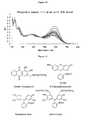
- Figure 11illustrates some representative indicators, which are featured with either a catechol moiety or multiple anionic residues.
- alizarin complexoneis used as the indicator for analysis of citrate concentrations.
- Alizarin complexonedisplays a relatively high binding affinity with Receptor 2 originating from the reversible boronic acid/diol interaction. This interaction between receptor and indicator is strong enough to allow the receptor/indicator complex to form to a great extent thus a large spectral change is attained. This is particularly advantageous in minimizing the errors when performing the citrate concentrate measurement activities. However, the strength of the association is still moderate enough to allow the indicator to be displaced by citrate to essentially completion.
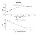
- a calibration curvemay be created by plotting the absorbance of a particular wavelength of light at known concentrations of citrate or another analyte. Figures 12A and 12B show representative calibration curves for citrate and calcium. Later, the concentration of an unknown sample may be determined simply by checking the UV-Vis absorption and comparing to the established calibration curve. It is important to account for temperature, however, as temperature affects the equilibrium significantly. Changes of room temperature during the analysis may lead to biased results.
- a detectable signalAfter a detectable signal has been generated, the signal is detected through the use of a Flow Injection Analysis (FIA) instrument.
- a Sequential Injection Analysis (SIA) Systemfrom Ocean Optics, Inc. may be used.
- this method of detectionmay be particularly advantageous as a general UV/vis spectrophotomer is quite space demanding.
- the SIA Systemhas dimensions of 5"x6"x6" and weighs about 8 lbs. It can also automate liquid transferring and mixing with precise control of volumes with the aid of a personal computer. A build-in compact UV-Vis photometer can then acquire the absorption spectra and the obtained data can be simultaneously analyzed.
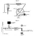
- the working principle of this SIA instrumentis shown in Figure 13 .
- sensing solution and dialysis fluidis aspirated into the mixing coil before further pushed into the built-in flowcell for optical signal measurement.
- This SIA deviceallows intermittent measurements to be done in an automatic fashion.
- the frequencycan be as fast as 1 minute or so depending on the programs for a specific application.
- an instrument based on the FIA working principle depicted in Figure 14may be used to measure in a continuous, real-time fashion.
- dialysis fluid to be testedis pumped into a line leading to the Flow-Injection-Analysis (FIA) instrument at a steady speed.
- An aliquot of sensing ensemble stock solution for a certain analyte, e.g., Ca 2+ , citrate, magnesium, phosphate, etc.is pumped into the line to get mixed with the dialysis fluid and induce an optical signal, which is collected by various detectors, e.g., UV-Vis spectrophotometer, CCD cameras, etc.
- optical signalsare generally preferred, other methods may be considered as well if they are advantageous in certain circumstances, including but not limited to near-infrared spectroscopy, Raman spectroscopy, Potentiometry, etc).
- a degassing modulecould be of use in case gas bubbles are generated during mixing.
- aqueous solution containing all the essential components of a typical dialysis fluid, except for citrate, Ca 2+ , Mg 2+ and CO 2is prepared.
- a 100 mM HEPES buffer with pH at 7.40is prepared from the above stock solution.
- the citrate sensing ensembleis prepared as following: 1) mixing 75 mL of MeOH and 25 mL HEPES buffer, 2) dissolving the particular amount of citrate Receptor 2 and alizarin complexone to make their concentrations 100 ⁇ M and 250 ⁇ M respectively.
- alizarin complexoneUpon the addition of citrate into the sensing ensemble, alizarin complexone is displaced from the cavity of Receptor 2, yielding to the larger affinity constant between Receptor 2 and citrate. Besides the boronic acid/diol interaction, charge pairing provides an extra driving force for the complexation between the citrate and the Receptor 2 ( Figure 15 ).
- Figure 16Ademonstrates the change in the absorption spectra of Alizarin complexone when in and outside of the receptor cavity. As the citrate concentration increases, absorption maxima of alizarin complexone at 337 nm and 540 nm increase while the maximum at 447 nm decreases. A calibration curve is made by plotting the solution absorbance at 540 nm vs. the corresponding citrate concentration ( Figure 16B ).
- a solution of Fura-2 at 25 ⁇ Mis prepared using the stock solution mentioned above. An aliquot of sample containing Ca 2+ is added and changes in the UV-Vis spectrum are observed. As the Ca 2+ concentration increases, the absorption maxima at 373 nm decreases while the maximum at 330 nm increases ( Figure 17A ). A calibration curve is made by plotting the solution absorbance at 373 nm vs. the corresponding Ca 2+ concentration ( Figure 17B ). The Ca 2+ concentration of an unknown sample may be obtained by its addition into the Fura-2 solution, checking the absorbance at 373 nm and comparing to the calibration curve.
- Fura-2displays such a high binding constant with Ca 2+ that: 1) Mg 2+ , another prevalent divalent cation present in the dialysate fluid, doesn't interfere, 2) citrate, which has a relatively weak binding affinity to Ca 2+ , doesn't displace Fura-2 in Ca 2+ binding.
- Stdevstandard deviation of the absorbance data from multiple replicates.
- VCcoefficient of variation calculated by Stdev/Abs.
- Concthe concentration of the analyte of the interest in the original ICU samples in the unit of millimolar. ICU samples are diluted with equal amount of 10mM HEPES buffer at pH 7.4 prior to the Ca 2+ measurements. ICU samples are diluted with 3 volumes of 100mM HEPES buffer at pH 7.4 and 12 volume of MeOH prior to the citrate measurements.
Landscapes
- Life Sciences & Earth Sciences (AREA)
- Chemical & Material Sciences (AREA)
- Health & Medical Sciences (AREA)
- Engineering & Computer Science (AREA)
- Organic Chemistry (AREA)
- Molecular Biology (AREA)
- Immunology (AREA)
- General Health & Medical Sciences (AREA)
- Biomedical Technology (AREA)
- Proteomics, Peptides & Aminoacids (AREA)
- Microbiology (AREA)
- Urology & Nephrology (AREA)
- Analytical Chemistry (AREA)
- Wood Science & Technology (AREA)
- Zoology (AREA)
- Biochemistry (AREA)
- Hematology (AREA)
- Biotechnology (AREA)
- Physics & Mathematics (AREA)
- Cell Biology (AREA)
- Pathology (AREA)
- Genetics & Genomics (AREA)
- General Engineering & Computer Science (AREA)
- Bioinformatics & Cheminformatics (AREA)
- Biophysics (AREA)
- Food Science & Technology (AREA)
- Medicinal Chemistry (AREA)
- General Physics & Mathematics (AREA)
- Inorganic Chemistry (AREA)
- Investigating Or Analysing Biological Materials (AREA)
- External Artificial Organs (AREA)
- Investigating Or Analysing Materials By The Use Of Chemical Reactions (AREA)
- Automatic Analysis And Handling Materials Therefor (AREA)
- Investigating Or Analyzing Non-Biological Materials By The Use Of Chemical Means (AREA)
- Measurement Of The Respiration, Hearing Ability, Form, And Blood Characteristics Of Living Organisms (AREA)
- Investigating Or Analysing Materials By Optical Means (AREA)
Description
- Continuous renal replacement therapy (CRRT) is a form of extracorporeal blood treatment (EBT) that is performed in the intensive care unit (ICU) for patients with acute renal failure (ARF) or end-stage renal disease (ESRD), who are often hemodynamically unstable with multiple co-morbidities. In a specific form of CRRT, continuous veno-venous hemofiltration (CVVH), blood is pumped through a hemofilter and uremic toxin-laden plasma ultrafiltrate is discarded at a rate of 1-10 liters per hour (convective removal of solutes). An equal amount of sterile crystalloid solution (replacement fluid, CRRT fluid) with physiological electrolyte and base concentrations is simultaneously infused into the blood circuit either before the hemofilter (pre-dilution) or after the hemofilter (post-dilution) to avoid volume depletion and hemodynamic collapse.
- From a theoretical and physiological point of view, when run continuously for 24 hours per day, CVVH is the closest of all available renal replacement therapy (RRT) modalities today to replicate the function of the native kidneys and the preferred treatment modality for critically ill patients with renal failure. Nevertheless, 90% of RRT in the ICU is performed as intermittent hemodialysis (IHD), sustained low efficiency dialysis (SLED), or sometimes as continuous veno-venous hemo-diafiltration (CVVHDF). Common to all of these latter methods of RRT is that the removal of most solutes is predominantly by the process of diffusion from blood plasma through the membrane of the hemofilter into the dialysis fluid. Diffusion is less efficient in the removal of larger solutes and also provides less predictable small solute movement than convection and therefore, from a theoretical standpoint, CVVH is a superior method of RRT.
- The most important reason for the limited use of CVVH in the ICU is that anticoagulation is mandatory to prevent clotting of the extracorporeal circuit in 24-hour treatments. Systemic anticoagulation has an unacceptable rate of major bleeding complications in critically ill patients and cannot be done safely. Similarly, extracorporeal blood treatments including plasmapheresis, plasma adsorption on specialized columns, blood banking procedures, lipid apheresis systems, plasma adsorption-based endotoxin removal, treatment with a bioartificial kidney device that contains live renal tubular cells, or with a liver replacement therapy circuit also require powerful anticoagulation..
- Regional citrate anticoagulation (RCA) has emerged as a possible solution to the clinical problem of circuit clotting without inducing any systemic bleeding tendency. Citrate, a trivalent anion, is present in the human plasma as an intermediate of metabolism. This ion chelates ionized calcium in the plasma resulting in a single negative Ca-citrate complex and decreased free ionized calcium levels. Since the coagulation cascade requires free ionized calcium for optimal function, blood clotting in the extracorporeal blood circuit (EBC) can be completely prevented by an infusion of citrate into the arterial (incoming) limb of the EBC. When the blood is passed through the extracorporeal processing unit, the anticoagulant effect can be fully reversed by the local infusion of free ionized calcium into the venous (return) limb of the EBC. Therefore, theoretically, regional citrate anticoagulation can be both very powerful and fully reversible without systemic (intra-patient) bleeding tendencies.
- Regional citrate anticoagulation has been performed for more than 20 years. Due to the lack of a simple and efficient protocol for the analysis of the critical composition of ultrafiltrate or blood, however, a number of complications associated with the practice of RCA occur. The following complications are well documented: hypernatremia; metabolic alkalosis; metabolic acidosis, hypocalcemia 1 (due to net calcium loss from the patient), hypocalcemia 2 (due to systemic citrate accumulation), rebound hypercalcemia (due to release of calcium from citrate after CVVH is stopped), hypophosphatemia, fluctuating levels of anticoagulation, nursing and physician errors, ionized hypomagnesemia, declining filter performance, trace metal depletion, etc. All these may be solved if real time monitoring of analytes, specifically citrate and ionized calcium is made possible.
- Additionally, using the above CVVH system, the patient's systemic plasma citrate level can fluctuate in the 0-3 mmol/L range depending on the body metabolism of citrate. Since an accumulation of systemic citrate to 3 mM could result in significant systemic ionized hypocalcemia unless the calcium infusion is increased to proportionally increase the plasma total calcium level, it is necessary to monitor the systemic citrate and total calcium levels.
- Laboratory testing of citrate and ionized calcium is not available in the routine clinical ICU setting. Marked changes in citrate and calcium levels can also develop in 2-3 hours during CVVH, too quickly for routine plasma chemistry monitoring every 6 hours to detect such problems in a timely manner before they have adverse clinical sequelae. The effluent fluid contains a wealth of information on the patient's plasma solute composition. This fluid is a clear crystalloid with a small amount of albumin, small peptides, and cytokines also present. The transparency and minimal viscosity of the effluent fluid provide for an ideal environment for an optical- and/or chemical sensor array. However, in current clinical practice, it is discarded without any further analysis.
- Furthermore, reduced Mg(II) concentration in blood, known as hypomagnesemia, may lead to weakness, muscle cramps, cardiac arrhythmia, increased irritability of the nervous system with tremors, athetosis, jerking, nystagmus and an extensor plantar reflex. In addition, there may be confusion, disorientation, hallucinations, depression, epileptic fits, hypertension, tachycardia and tetany. However, due to the lack of convenient and reliable clinical monitoring protocol of magnesium, a 2.5:1 molar ratio between total plasma calcium and total plasma magnesium is usually maintained by using a high-Mg commercial replacement fluid. Phosphate losses can also be very large and can quickly lead to severe hypophosphatemia with high daily clearance goals during CVVH unless phosphate is added to the CRRT replacement fluid.
- A need exists to develop an effective, real time method to measure the level of analytes, such as citrate, ionized calcium, magnesium, phosphate, etc., in the clinical setting. Such a method may take advantage of the effluent fluid that is currently discarded.
- The present disclosure relates generally to methods of determining the presence and/or concentration level of an analyte in a sample as set out in the claims. More particularly, in some embodiments, the present disclosure relates to methods of measuring the concentration of citrate, ionized calcium, magnesium and/or phosphate in a sample.
- In one embodiment, the present disclosure provides a method for continuous, real-time monitoring of concentration levels of an analyte in a biological fluid comprising an extracorporeal blood circuit effluent fluid produced on a hemofilter or a dialyzer device with hemofiltration or dialysis or any combination of these two processes, the method comprising: providing an analyte; providing an analyte receptor and an indicator, wherein at least a portion of the analyte receptor and the indicator form a receptor/indicator complex; contacting the receptor/indicator complex with the analyte; and allowing the analyte to interact with the receptor/indicator complex so as to generate a detectable signal; and detecting the signal by using a Flow Injection Analysis instrument.
- In another embodiment, the present disclosure provides a system for continuous, real-time monitoring of concentration levels of an analyte in a biological fluid comprising an extracorporeal blood circuit effluent fluid produced on a hemofilter or a dialyzer device with hemofiltration or dialysis or any combination of these two processes, the system comprising: a receptor/indicator complex comprising an analyte receptor and an indicator; and an analyte, wherein the analyte will displace the indicator in the receptor/indicator complex; and wherein the displaced indicator will generate a detectable signal; and a Flow Injection Analysis instrument.
- The features and advantages of the present disclosure will be readily apparent to those skilled in the art upon a reading of the description of the embodiments that follows.
- A more complete understanding of this disclosure may be acquired by referring to the following description taken in combination with the accompanying figures in which:
FIGURE 1 is an image depicting a mechanism of analyte sensing via an indicator displacement assay, according to one embodiment.FIGURE 2 is an image depicting a mechanism of analyte sensing via an analyte (Ca2+) binding to a receptor/indicator complex (Fura-2), according to one embodiment.FIGURES 3A and3B depict the structure of representative citrate receptors, according to one embodiment.FIGURE 4 depicts several representative Ca2+ receptors, according to one embodiment.FIGURE 5 depicts several representative Mg2+ receptors, according to one embodiment.FIGURE 6 depicts the synthesis scheme of Mg2+ receptors 2 and 3 (Figure 5 ) from known compounds, according to one embodiment.FIGURE 7 depicts representative Mg2+ receptors, according to one embodiment.FIGURE 8 depicts representative phosphate receptors based on H-bpmp, according to one embodimentFIGURE 9 is an image depicting a mechanism of analyte sensing via indicator displacement assay using H-bpmp, according to one embodiment.FIGURE 10 depicts changes of the solution UV-Vis spectra containing a H-bpmp receptor and a pyrocatechol violet indicator upon the addition of a phosphate analyte, according to one embodiment.FIGURE 11 depicts the structure of representative indicators, according to one embodiment.FIGURES 12A and 12B depict sample calibration curves for citrate (11A) and Ca2+(11B), according to one embodiment.FIGURE 13 depicts the working principle of a Flow-Injection-Analysis ("FIA") instrument, according to one embodiment.FIGURE 14 is a schematic representation of a FIA instrument, according to one embodiment.FIGURE 15 depicts the proposed binding modes of Receptor 2 with alizarin complexone and citrate.FIGURE 16A depicts changes of the solution UV-Vis spectra containing both Receptor 2, and Alizarin Complexone upon addition of citrate, according to one embodiment. Arrows indicate the spectral changes upon increasing citrate concentration.FIGURE 16B depicts the extrapolated calibration curve of citrate concentration by monitoring the absorbance at 540 nm, according to one embodiment.FIGURE 17A depicts changes of the solution UV-Vis spectra containing Fura-2 upon addition of Ca2+, according to one embodiment. Arrows indicates the spectral changes upon increasing the Ca2+ concentration.FIGURE 17B depicts extrapolated calibration curve of the Ca2+ concentration by monitoring the solution absorbance at 373 nm, according to one embodiment.- While the present disclosure is susceptible to various modifications and alternative forms, specific example embodiments have been shown in the figures and are herein described in more detail. It should be understood, however, that the description of specific example embodiments is not intended to limit the disclosure to the particular forms disclosed, but on the contrary, this disclosure is to cover all modifications and equivalents as defined by the appended claims.
- The present disclosure relates generally to methods of determining the presence and/or concentration level of an analyte in a sample as set out in the claims. More particularly, in some embodiments, the present disclosure relates to methods of determining the presence and/or concentration level of citrate, ionized calcium, magnesium and/or phosphate in a sample.
- In one embodiment, the present disclosure provides a method for continuous, real-time monitoring of concentration levels of an analyte in a biological fluid comprising an extracorporeal blood circuit effluent fluid produced on a hemofilter or a dialyzer device with hemofiltration or dialysis or any combination of these two processes, the method comprising: providing an analyte; providing an analyte receptor and an indicator, wherein at least a portion of the analyte receptor and the indicator form a receptor/indicator complex; contacting the receptor/indicator complex with the analyte; and allowing the analyte to interact with the receptor/indicator complex so as to generate a detectable signal; and detecting the signal by using a Flow Injection Analysis instrument. In some embodiments, the analyte displaces at least a portion of the indicator in the receptor/indicator complex to form a receptor/analyte complex. In other embodiments, the analyte may bind to the receptor/indicator complex.
- The present disclosure provides methods that may solve many of the clinical problems associated with CVVH or similar procedures by providing methods that enable the monitoring of analyte concentration levels, such as citrate, calcium, magnesium and phosphate, in real time. For maximum safety, in certain embodiments, the methods may provide a warning of any change in systemic analyte levels so as to prompt the monitoring personnel to review and adjust the treatment settings to ensure the safe continuation of the CVVH or similar procedure. Furthermore, in some embodiments, the methods of the present disclosure may provide information for the fine-tuning of dosages, including calcium plus magnesium dosing, and also monitor the metabolic function of the liver through monitoring the rate of citrate metabolism.
- Due to the interaction between citrate and free ionized calcium, the goals of the present disclosure may be achieved by providing a method to measure the concentration levels of an analyte, such as citrate and/or ionized calcium (e.g., free and/or total ionized calcium) in a sample, such as a bodily fluid. In one embodiment, a receptor and an indicator may be provided in the filter effluent fluid line during CVVH. This allows for the indirect measurement of the analyte level in the patient's systemic blood.
- In one embodiment, the methods of the present disclosure may utilize an indicator displacement assay (IDA) for the quantification of an analyte, such as citrate or a different analyte.
Figure 1 contains an image depicting an IDA, according to one embodiment of the present disclosure. As shown inFigure 1 , IDA is a process in which an analyte receptor is initially allowed to form a weakly associated complex with an indicator, such as a chromophore or fluorophore, and reach an equilibrium. This equilibrium will be affected when an analyte bearing better structural complimentarity to the receptor than the indicator, is introduced into the system. The receptor/indicator complex will start to diminish allowing the receptor/analyte complex to form. At the same time, the indicator in the cavity of the receptor will be released. Due to the variation of the chemical environment of the indicator, its output signal, usually absorption or emission spectra will be modified. This change may be conveniently used in analysis of the analyte concentration provided necessary parameters describing the related equilibria are known. - In another embodiment, the present disclosure provides for the detection of an analyte by allowing the analyte to bind to a receptor/indicator complex. After analyte binding, a detectable signal is produced. One example is shown in
Figure 2 , which contains an image depicting the binding of ionized calcium to the receptor/indicator complex, Fura-2. - The success of the methods of the present disclosure depend, at least in part, upon the affinity of the receptor or the receptor/indicator complex to bind to the analyte. A variety of different receptors may be used. In certain embodiments, where the analyte is citrate, the receptor is based upon a 2,4,6-triethylbenzene core. However, the receptor can use any scaffold that brings together the functional groups. Various functional groups, including but not limited to guanidinium and phenylboronic acids, are substituted in the 1, 3, and 5 positions. Guanidinium is a favorable functional group because its geometry is conducive for the binding of carboxylates present in citrate and it remains protonated over a wide range pH range. Phenylboronic acid can form robust boronate ester with the α-hydroxy carboxylate moiety of citrate via covalent bonds and represents another favorable functional group for citrate binding.
Figures 3A and3B illustrate several representative citrate receptors. Each of these citrate receptors can be easily synthesized by one of skill in the art. Initial trials have shown that Receptor 2 may be a preferred receptor for citrate. The interactions between the citrate receptor and glucose, fructose, or lactate are insignificant enough to be neglected. Other compounds or ions such as bicarbonate, chloride, phosphate and β-hydroxybutyrate are also expected to cause no interferences. - In those embodiments where the analyte is calcium, a variety of Ca2+ receptors (only some of which are shown in
Figure 4 ) may be used and are now commercially available from different vendors. Many of them have the common EDTA-mimicking moiety, which forms a stable complex with Ca2+ in solution. When such a moiety is appended to a chromophore or fluorophore, modified spectroscopic properties occur after complexation. In one embodiment, the calcium receptor may be Fura-2, which is commercially available from Invitrogen. Owing to its high complexation constant with Ca2+, Fura-2 could extract the Ca2+ from the complexes with competing anions, such as citrate3-, PO43-, etc. Additionally, Fura-2 shows high selectivity toward Ca2+ over other ions such as Mg2+, Na+, K+, etc. The absorption band of Fura-2 is centered at 273 nm. This allows for the detection of Ca2+ to take place essentially free from interferences caused by residual proteins in the dialysis fluid, which produce absorption generally below 330 nm. - In those embodiments where the analyte is magnesium, a variety of Mg2+ receptors may be used. As would be recognized by one of skill in the art, most current commercially available Mg2+ receptors show higher affinity towards Ca2+. Therefore, when choosing an appropriate Mg2+ receptor, receptors that show an affinity to Mg2+ over Ca2+ may be selected.
- In one embodiment, a suitable Mg2+ receptor may include those receptors shown in
Figure 5 . Receptors 2 and 3 (fromFigure 5 ) may be synthesized from the corresponding acridine or xanthene precursors, as shown inFigure 6 . The two fluorine atoms of 4,5-difluoroacridine (4) may be displaced via SNAR mechanism when treated with an appropriate nucleophile. It was reported that negatively charged phophorous species displace fluorine atoms while neutral phosphine does conjugate addition at C-9. Double ortho-lithiation of 9,9-dimethylxanthene (6) is effected by refluxing with n-BuLi and TMEDA in pentane for 10 mins. Quenching with chlorodiehtylphosphate furnishes the ethylphosphonate intermediates. Both 5 and 7 may be easily hydrolyzied by refluxing in concentrated HCl solution to yield the desired receptor 2 and 3, respectively. In addition, the steric and electronic properties of receptors 2 or 3 (fromFigure 5 ) may be further fine tuned via alkylation of the phosphonate group as shown inFigure 7 . - The present disclosure also allows for the testing of phosphate. A number of phosphate receptors with various degrees of selectivity are known in the art. In one embodiment, a suitable phosphate receptor may include those receptors shown in
Figure 8 . A preferred embodiment uses H-bpmp as reported in (Han, M. S. et. al. Angew. Chem., Int. Ed. 2002, 41, 3809-3811) because it is reported to display selectivity over common anions, such as chloride, bicarbonates, nitrates, etc. The receptor may be synthesized by following the literature procedures. A sensing mechanism according to one embodiments is shown inFigure 9 . Pyrocatechol violet (PV) can coordinate to the two Zn2+ metal centers in the absence of phosphate or other competing anions. Upon addition of phosphate solution, PV will get displaced and changes to its protonation states will cause the solution color to change from light navy to brownish yellow. - Though phosphate leads to a significant spectral change, as depicted in
Figure 10 , initial results have shown that citrate can cause severe interferences to the phosphate sensing due to the fact that citrate displays a higher affinity towards the H-bpmp receptor. In such systems where two interfering variants are to be determined, it would be necessary to introduce the use of pattern recognition. When phosphate sensing is performed, the change to the readout signal is not only determined by the concentration of phosphate but also the concentration of citrate in the solution. The same is also true when citrate sensing is performed, though the influence of phosphate is minimal. A mathematical treatment such as artificial neural network (ANN) processing of the raw data can help extrapolate the actual concentration of both phosphate and citrate. In one embodiment, processing of UV-Vis measurements may be accomplished using Statistica Artificial Neural Network software. - The use of a solvent system comprising 75% MeOH: 25% aqueous buffer (v/v) instead of 100% aqueous buffer solution is found to improve selectivity toward phosphate over citrate. This may lead to higher accuracy in phosphate measurements. Additionally, the stability of the phosphate sensing ensemble solution is also dramatically improved in such solvent system.
- Indicators that are suitable for use in the present disclose include those indicators that are capable of producing a detectable signal when displaced from a receptor/indicator complex by an analyte or those that are capable of producing a detectable signal when an analyte is bound to the receptor/indicator complex. Examples of suitable indicators include, but are not limited to, a chromophore, a fluorophore, alizarin complexone, 5-carboxyfluorescein, pyrocatechol violet, and xylenol orange.
Figure 11 illustrates some representative indicators, which are featured with either a catechol moiety or multiple anionic residues. In one embodiment, alizarin complexone is used as the indicator for analysis of citrate concentrations. Alizarin complexone displays a relatively high binding affinity with Receptor 2 originating from the reversible boronic acid/diol interaction. This interaction between receptor and indicator is strong enough to allow the receptor/indicator complex to form to a great extent thus a large spectral change is attained. This is particularly advantageous in minimizing the errors when performing the citrate concentrate measurement activities. However, the strength of the association is still moderate enough to allow the indicator to be displaced by citrate to essentially completion. A calibration curve may be created by plotting the absorbance of a particular wavelength of light at known concentrations of citrate or another analyte.Figures 12A and 12B show representative calibration curves for citrate and calcium. Later, the concentration of an unknown sample may be determined simply by checking the UV-Vis absorption and comparing to the established calibration curve. It is important to account for temperature, however, as temperature affects the equilibrium significantly. Changes of room temperature during the analysis may lead to biased results. - After a detectable signal has been generated, the signal is detected through the use of a Flow Injection Analysis (FIA) instrument. For example, a Sequential Injection Analysis (SIA) System from Ocean Optics, Inc. may be used. In some embodiments, this method of detection may be particularly advantageous as a general UV/vis spectrophotomer is quite space demanding. The SIA System has dimensions of 5"x6"x6" and weighs about 8 lbs. It can also automate liquid transferring and mixing with precise control of volumes with the aid of a personal computer. A build-in compact UV-Vis photometer can then acquire the absorption spectra and the obtained data can be simultaneously analyzed. The working principle of this SIA instrument is shown in
Figure 13 . An aliquot of sensing solution and dialysis fluid is aspirated into the mixing coil before further pushed into the built-in flowcell for optical signal measurement. This SIA device allows intermittent measurements to be done in an automatic fashion. The frequency can be as fast as 1 minute or so depending on the programs for a specific application. - In another embodiment, an instrument based on the FIA working principle depicted in
Figure 14 may be used to measure in a continuous, real-time fashion. In one embodiment, dialysis fluid to be tested is pumped into a line leading to the Flow-Injection-Analysis (FIA) instrument at a steady speed. An aliquot of sensing ensemble stock solution for a certain analyte, e.g., Ca2+, citrate, magnesium, phosphate, etc., is pumped into the line to get mixed with the dialysis fluid and induce an optical signal, which is collected by various detectors, e.g., UV-Vis spectrophotometer, CCD cameras, etc. Though optical signals are generally preferred, other methods may be considered as well if they are advantageous in certain circumstances, including but not limited to near-infrared spectroscopy, Raman spectroscopy, Potentiometry, etc). A degassing module could be of use in case gas bubbles are generated during mixing. - To facilitate a better understanding of the present disclosure, the following examples of certain aspects of some embodiments are given. In no way should the following examples be read to limit, or define, the entire scope of the disclosure.
- An aqueous solution containing all the essential components of a typical dialysis fluid, except for citrate, Ca2+, Mg2+ and CO2 is prepared. A 100 mM HEPES buffer with pH at 7.40 is prepared from the above stock solution. The citrate sensing ensemble is prepared as following: 1) mixing 75 mL of MeOH and 25 mL HEPES buffer, 2) dissolving the particular amount of citrate Receptor 2 and alizarin complexone to make their concentrations 100 µM and 250 µM respectively.
- Upon the addition of citrate into the sensing ensemble, alizarin complexone is displaced from the cavity of Receptor 2, yielding to the larger affinity constant between Receptor 2 and citrate. Besides the boronic acid/diol interaction, charge pairing provides an extra driving force for the complexation between the citrate and the Receptor 2 (
Figure 15 ). Figure 16A demonstrates the change in the absorption spectra of Alizarin complexone when in and outside of the receptor cavity. As the citrate concentration increases, absorption maxima of alizarin complexone at 337 nm and 540 nm increase while the maximum at 447 nm decreases. A calibration curve is made by plotting the solution absorbance at 540 nm vs. the corresponding citrate concentration (Figure 16B ).- A solution of Fura-2 at 25 µM is prepared using the stock solution mentioned above. An aliquot of sample containing Ca2+ is added and changes in the UV-Vis spectrum are observed. As the Ca2+ concentration increases, the absorption maxima at 373 nm decreases while the maximum at 330 nm increases (
Figure 17A ). A calibration curve is made by plotting the solution absorbance at 373 nm vs. the corresponding Ca2+ concentration (Figure 17B ). The Ca2+ concentration of an unknown sample may be obtained by its addition into the Fura-2 solution, checking the absorbance at 373 nm and comparing to the calibration curve. Fura-2 displays such a high binding constant with Ca2+ that: 1) Mg2+, another prevalent divalent cation present in the dialysate fluid, doesn't interfere, 2) citrate, which has a relatively weak binding affinity to Ca2+, doesn't displace Fura-2 in Ca2+ binding. - Eight patient dialysate fluid sample obtained from ICU unit of the Henry Ford Hospital was tested for [Ca2+] and [Citrate] using the calibration curves shown in
Figures 12A and 12B . The Ca2+ and citrate concentrations in the dialysate fluid were calculated based on the absorption spectra of the resulting solutions (Table 1).TABLE 1 Sample ID ICU-1 ICU-2 ICU-3 ICU-4 ICU-5 ICU-6 ICU-7 ICU-8 Ca2+ data Abs 0.8895 0.9162 0.9369 0.8986 0.8232 0.7823 0.7511 0.7013 Stdev 0.0278 0.0281 0.0301 0.0270 0.0278 0.0236 0.0222 0.0249 VC 0.031 0.031 0.032 0.030 0.034 0.030 0.030 0.035 Conc (mM) 0.063 0.030 0.004 0.052 0.137 0.180 0.214 0.272 Citrate data Abs 0.1682 0.1682 0.1661 0.1650 0.1850 0.1872 0.1845 0.1720 Stdev 0.0028 0.0026 0.0022 0.0049 0.0031 0.0032 0.0044 0.0013 VC 0.017 0.015 0.013 0.030 0.017 0.017 0.024 0.008 Conc (mM) 3.10 3.10 2.96 2.89 4.75 5.00 4.70 3.36 Notes: Abs: average absorbance from multiple replicates. Stdev: standard deviation of the absorbance data from multiple replicates. VC: coefficient of variation calculated by Stdev/Abs. Conc: the concentration of the analyte of the interest in the original ICU samples in the unit of millimolar. ICU samples are diluted with equal amount of 10mM HEPES buffer at pH 7.4 prior to the Ca2+ measurements. ICU samples are diluted with 3 volumes of 100mM HEPES buffer at pH 7.4 and 12 volume of MeOH prior to the citrate measurements.
Claims (12)
- A method for continuous, real-time monitoring of concentration levels of an analyte in a biological fluid comprising an extracorporeal blood circuit effluent fluid produced on a hemofilter or a dialyzer device with hemofiltration or dialysis or any combination of these two processes, the method comprising continuously:providing a biological fluid comprising an analyte;providing an analyte receptor and an indicator, wherein at least a portion of the analyte receptor and the indicator form a receptor/indicator complex;contacting the receptor/indicator complex with the analyte;allowing the analyte to interact with the receptor/indicator complex so as to generate a detectable signal; anddetecting the signal by using a Flow Injection Analysis instrument.
- A system for continuous, real-time monitoring of concentration levels of an analyte in a biological fluid comprising an extracorporeal blood circuit effluent fluid produced on a hemofilter or a dialyzer device with hemofiltration or dialysis or any combination of these two processes, the system comprising:a receptor/indicator complex comprising an analyte receptor and an indicator; and an analyte, wherein the analyte will displace the indicator in the receptor/indicator complex; and wherein the displaced indicator will generate a detectable signal; anda Flow Injection Analysis instrument.
- The method of Claim 1, or the system of Claim 2, wherein the biological fluid comprises an extracorporeal blood circuit effluent fluid produced on a hemofilter or a dialyzer device with hemofiltration or dialysis or any combination of these two processes.
- The method of Claims 1 or 3, wherein the concentration level of the analyte in the biological fluid is monitored.
- The method of Claims 1, 3 or 4, further comprising correlating the detectable signal with a calibration curve to determine a concentration of the analyte.
- The method of Claim 1 or system of Claim 2, wherein the analyte is selected from the group consisting of: ionized calcium, citrate, phosphate and magnesium.
- The method of Claim 1, or system of Claim 2, wherein allowing the analyte to interact with the receptor/indicator complex comprises allowing the analyte to displace at least a portion of the indicator in the receptor/indicator complex to form a receptor/analyte complex.
- The method of Claim 1, or system of Claim 2, wherein allowing the analyte to interact with the receptor/indicator complex comprises allowing the analyte to bind to the receptor/indicator complex.
- The method of Claim 1, or system of Claim 2, wherein the indicator comprises at least one indicator selected from the group consisting of: a chromophore, a fluorophore, alizarin complexone, 5-carboxyfluorescein, pyrocatechol violet, and xylenol orange.
- The method of Claim 1, or system of Claim 2, wherein the analyte comprises phosphate and citrate.
- The method of Claim 10, further comprising using a mathematical treatment to extrapolate the concentration of phosphate and citrate.
- The method of Claim 11, wherein the mathematical treatment comprises an artificial neural network (ANN).
Applications Claiming Priority (2)
| Application Number | Priority Date | Filing Date | Title |
|---|---|---|---|
| US22228509P | 2009-07-01 | 2009-07-01 | |
| PCT/US2010/040543WO2011002850A1 (en) | 2009-07-01 | 2010-06-30 | Methods of determining the presence and/or concentration of an analyte in a sample |
Publications (3)
| Publication Number | Publication Date |
|---|---|
| EP2449129A1 EP2449129A1 (en) | 2012-05-09 |
| EP2449129A4 EP2449129A4 (en) | 2012-05-09 |
| EP2449129B1true EP2449129B1 (en) | 2014-04-16 |
Family
ID=43411421
Family Applications (1)
| Application Number | Title | Priority Date | Filing Date |
|---|---|---|---|
| EP10794686.5ANot-in-forceEP2449129B1 (en) | 2009-07-01 | 2010-06-30 | Methods of determining the presence and/or concentration of an analyte in a sample |
Country Status (6)
| Country | Link |
|---|---|
| US (1) | US20120115248A1 (en) |
| EP (1) | EP2449129B1 (en) |
| JP (2) | JP5823389B2 (en) |
| AU (1) | AU2010266335A1 (en) |
| CA (1) | CA2766597A1 (en) |
| WO (1) | WO2011002850A1 (en) |
Families Citing this family (63)
| Publication number | Priority date | Publication date | Assignee | Title |
|---|---|---|---|---|
| WO2006086490A1 (en) | 2005-02-07 | 2006-08-17 | Medtronic, Inc. | Ion imbalance detector |
| US8728025B2 (en) | 2008-03-10 | 2014-05-20 | S.E.A. Medical Systems, Inc. | Intravenous fluid monitoring |
| US9052276B2 (en) | 2009-06-08 | 2015-06-09 | S.E.A. Medical Systems, Inc. | Systems and methods for the identification of compounds using admittance spectroscopy |
| US9399091B2 (en) | 2009-09-30 | 2016-07-26 | Medtronic, Inc. | System and method to regulate ultrafiltration |
| US9456755B2 (en) | 2011-04-29 | 2016-10-04 | Medtronic, Inc. | Method and device to monitor patients with kidney disease |
| US9848778B2 (en) | 2011-04-29 | 2017-12-26 | Medtronic, Inc. | Method and device to monitor patients with kidney disease |
| US9561316B2 (en) | 2011-04-29 | 2017-02-07 | Medtronic, Inc. | Intersession monitoring for blood fluid removal therapy |
| CN103889481B (en) | 2011-08-02 | 2016-03-09 | 美敦力公司 | Hemodialysis system with flow path with controlled compliance volume |
| EP2744537B1 (en) | 2011-08-16 | 2018-01-24 | Medtronic, Inc. | Modular hemodialysis system |
| EP2800592B1 (en) | 2012-01-04 | 2019-03-06 | Medtronic Inc. | Multi-staged filtration system for blood fluid removal |
| US10905816B2 (en) | 2012-12-10 | 2021-02-02 | Medtronic, Inc. | Sodium management system for hemodialysis |
| US9713666B2 (en) | 2013-01-09 | 2017-07-25 | Medtronic, Inc. | Recirculating dialysate fluid circuit for blood measurement |
| US9707328B2 (en) | 2013-01-09 | 2017-07-18 | Medtronic, Inc. | Sorbent cartridge to measure solute concentrations |
| US11154648B2 (en) | 2013-01-09 | 2021-10-26 | Medtronic, Inc. | Fluid circuits for sorbent cartridge with sensors |
| US11565029B2 (en) | 2013-01-09 | 2023-01-31 | Medtronic, Inc. | Sorbent cartridge with electrodes |
| US9623164B2 (en) | 2013-02-01 | 2017-04-18 | Medtronic, Inc. | Systems and methods for multifunctional volumetric fluid control |
| US10850016B2 (en) | 2013-02-01 | 2020-12-01 | Medtronic, Inc. | Modular fluid therapy system having jumpered flow paths and systems and methods for cleaning and disinfection |
| US10010663B2 (en) | 2013-02-01 | 2018-07-03 | Medtronic, Inc. | Fluid circuit for delivery of renal replacement therapies |
| US10543052B2 (en) | 2013-02-01 | 2020-01-28 | Medtronic, Inc. | Portable dialysis cabinet |
| US9526822B2 (en) | 2013-02-01 | 2016-12-27 | Medtronic, Inc. | Sodium and buffer source cartridges for use in a modular controlled compliant flow path |
| US9827361B2 (en)* | 2013-02-02 | 2017-11-28 | Medtronic, Inc. | pH buffer measurement system for hemodialysis systems |
| US9144640B2 (en) | 2013-02-02 | 2015-09-29 | Medtronic, Inc. | Sorbent cartridge configurations for improved dialysate regeneration |
| US20160018347A1 (en)* | 2013-03-11 | 2016-01-21 | S.E.A. Medical Systems, Inc. | Designs, systems, configurations, and methods for immittance spectroscopy |
| US10076283B2 (en) | 2013-11-04 | 2018-09-18 | Medtronic, Inc. | Method and device to manage fluid volumes in the body |
| US10537875B2 (en) | 2013-11-26 | 2020-01-21 | Medtronic, Inc. | Precision recharging of sorbent materials using patient and session data |
| US9884145B2 (en) | 2013-11-26 | 2018-02-06 | Medtronic, Inc. | Parallel modules for in-line recharging of sorbents using alternate duty cycles |
| EP3073911B8 (en) | 2013-11-27 | 2025-09-03 | Mozarc Medical US LLC | Precision dialysis monitoring and synchonization system |
| ES2989503T3 (en) | 2014-06-24 | 2024-11-26 | Mozarc Medical Us Llc | Modular dialysate regeneration assembly |
| WO2015199768A1 (en) | 2014-06-24 | 2015-12-30 | Medtronic, Inc. | Stacked sorbent assembly |
| US10874787B2 (en) | 2014-12-10 | 2020-12-29 | Medtronic, Inc. | Degassing system for dialysis |
| US10098993B2 (en) | 2014-12-10 | 2018-10-16 | Medtronic, Inc. | Sensing and storage system for fluid balance |
| US9895479B2 (en) | 2014-12-10 | 2018-02-20 | Medtronic, Inc. | Water management system for use in dialysis |
| US9713665B2 (en) | 2014-12-10 | 2017-07-25 | Medtronic, Inc. | Degassing system for dialysis |
| WO2017078965A1 (en) | 2015-11-06 | 2017-05-11 | Medtronic, Inc | Dialysis prescription optimization for decreased arrhythmias |
| WO2017160840A1 (en) | 2016-03-14 | 2017-09-21 | Diassess Inc. | Selectively vented biological assay devices and associated methods |
| AU2017232340B2 (en) | 2016-03-14 | 2022-04-28 | Pfizer Inc. | Systems and methods for performing biological assays |
| WO2017160839A1 (en) | 2016-03-14 | 2017-09-21 | Diassess Inc. | Devices and methods for modifying optical properties |
| US10874790B2 (en) | 2016-08-10 | 2020-12-29 | Medtronic, Inc. | Peritoneal dialysis intracycle osmotic agent adjustment |
| US12329892B2 (en) | 2016-04-04 | 2025-06-17 | Mozarc Medical Us Llc | Dextrose concentration sensor for a peritoneal dialysis system |
| US10994064B2 (en) | 2016-08-10 | 2021-05-04 | Medtronic, Inc. | Peritoneal dialysate flow path sensing |
| US11013843B2 (en) | 2016-09-09 | 2021-05-25 | Medtronic, Inc. | Peritoneal dialysis fluid testing system |
| US10981148B2 (en) | 2016-11-29 | 2021-04-20 | Medtronic, Inc. | Zirconium oxide module conditioning |
| US11080848B2 (en) | 2017-04-06 | 2021-08-03 | Lucira Health, Inc. | Image-based disease diagnostics using a mobile device |
| US10960381B2 (en) | 2017-06-15 | 2021-03-30 | Medtronic, Inc. | Zirconium phosphate disinfection recharging and conditioning |
| WO2019055135A1 (en) | 2017-09-14 | 2019-03-21 | Diassess Inc. | Multiplexed biological assay device with electronic readout |
| US11278654B2 (en) | 2017-12-07 | 2022-03-22 | Medtronic, Inc. | Pneumatic manifold for a dialysis system |
| US11033667B2 (en) | 2018-02-02 | 2021-06-15 | Medtronic, Inc. | Sorbent manifold for a dialysis system |
| US11110215B2 (en) | 2018-02-23 | 2021-09-07 | Medtronic, Inc. | Degasser and vent manifolds for dialysis |
| US12089930B2 (en) | 2018-03-05 | 2024-09-17 | Marquette University | Method and apparatus for non-invasive hemoglobin level prediction |
| US12285552B2 (en) | 2018-08-14 | 2025-04-29 | Mozarc Medical Us Llc | Precision dialysis therapy based on sorbent effluent analysis |
| US11213616B2 (en) | 2018-08-24 | 2022-01-04 | Medtronic, Inc. | Recharge solution for zirconium phosphate |
| US11806457B2 (en) | 2018-11-16 | 2023-11-07 | Mozarc Medical Us Llc | Peritoneal dialysis adequacy meaurements |
| US11806456B2 (en) | 2018-12-10 | 2023-11-07 | Mozarc Medical Us Llc | Precision peritoneal dialysis therapy based on dialysis adequacy measurements |
| US12433976B2 (en) | 2019-01-08 | 2025-10-07 | Mozarc Medical Us Llc | Bicarbonate sensor for dialysis |
| EP4028378A4 (en) | 2019-09-10 | 2024-03-13 | Countertrace LLC | Hexasubstituted benzenes, surfaces modified therewith, and associated methods |
| WO2021050669A1 (en) | 2019-09-10 | 2021-03-18 | Countertrace Llc | Fluid analyses and sensor constructs employing hexasubstituted benzenes |
| US12128165B2 (en) | 2020-04-27 | 2024-10-29 | Mozarc Medical Us Llc | Dual stage degasser |
| US12397093B2 (en) | 2021-05-18 | 2025-08-26 | Mozarc Medical Us Llc | Sorbent cartridge designs |
| US12154673B2 (en) | 2021-08-02 | 2024-11-26 | Mozarc Medical Us Llc | Artificial intelligence assisted home therapy settings for dialysis |
| US11850344B2 (en) | 2021-08-11 | 2023-12-26 | Mozarc Medical Us Llc | Gas bubble sensor |
| CN113588579B (en)* | 2021-08-23 | 2024-03-01 | 重庆山外山血液净化技术股份有限公司 | Blood ion concentration detection device and method, and calcium ion concentration detection method |
| US11965763B2 (en) | 2021-11-12 | 2024-04-23 | Mozarc Medical Us Llc | Determining fluid flow across rotary pump |
| US11944733B2 (en) | 2021-11-18 | 2024-04-02 | Mozarc Medical Us Llc | Sodium and bicarbonate control |
Family Cites Families (16)
| Publication number | Priority date | Publication date | Assignee | Title |
|---|---|---|---|---|
| JPS612867A (en)* | 1984-06-15 | 1986-01-08 | 株式会社日立製作所 | Artificial kidney diagnosis monitor apparatus |
| WO2001006253A2 (en)* | 1999-07-16 | 2001-01-25 | Board Of Regents, The University Of Texas System | Detection system based on an analyte reactive particle |
| WO2001055702A1 (en)* | 2000-01-31 | 2001-08-02 | Board Of Regents, The University Of Texas System | Portable sensor array system |
| AU2002229152A1 (en)* | 2000-07-28 | 2002-02-18 | Japan Science And Technology Corporation | Fluorescent probe for magnesium ion determination |
| WO2002061392A2 (en)* | 2001-01-31 | 2002-08-08 | Board Of Regents, The University Of Texas System | Method and apparatus for the confinement of materials in a micromachined chemical sensor array |
| AU2002349700A1 (en)* | 2001-11-22 | 2003-06-10 | Japan Science And Technology Corporation | Method for measuring concentrations of chemical substances, method for measuring concentrations of ion species, and sensor therefor |
| JP4138331B2 (en)* | 2002-02-22 | 2008-08-27 | 独立行政法人科学技術振興機構 | Fluorescent sensor for phosphate ion and phosphorylated peptide |
| US6801316B2 (en)* | 2002-07-19 | 2004-10-05 | Optix Lp | Measurement of an analyte concentration in a scattering medium |
| US7302349B2 (en)* | 2002-08-16 | 2007-11-27 | Lattec I/S | System and a method for observing and predicting a physiological state of an animal |
| JP4326207B2 (en)* | 2002-11-12 | 2009-09-02 | キヤノンセミコンダクターエクィップメント株式会社 | Metal detection method and apparatus |
| DE102004023402A1 (en)* | 2004-05-12 | 2005-12-08 | Roche Diagnostics Gmbh | Method for increasing the dynamic measuring range of, in particular immunological test elements based on specific binding reactions |
| JP5254043B2 (en)* | 2006-02-22 | 2013-08-07 | ヘンリー フォード ヘルス システム | Topical citrate anticoagulant delivery system and method to extracorporeal blood circuit |
| US8133194B2 (en)* | 2006-02-22 | 2012-03-13 | Henry Ford Health System | System and method for delivery of regional citrate anticoagulation to extracorporeal blood circuits |
| JP4855854B2 (en)* | 2006-07-10 | 2012-01-18 | 川澄化学工業株式会社 | Chemiluminescent urea sensor for hemodialysis and urea measurement method in hemodialysis |
| US20100112680A1 (en)* | 2006-07-11 | 2010-05-06 | Paul Nigel Brockwell | Indicator system for determining analyte concentration |
| WO2010024224A1 (en)* | 2008-08-26 | 2010-03-04 | 財団法人岡山県産業振興財団 | Urea concentration measurement method and urea concentration measurement apparatus |
- 2010
- 2010-06-30EPEP10794686.5Apatent/EP2449129B1/ennot_activeNot-in-force
- 2010-06-30WOPCT/US2010/040543patent/WO2011002850A1/enactiveApplication Filing
- 2010-06-30CACA2766597Apatent/CA2766597A1/ennot_activeAbandoned
- 2010-06-30JPJP2012517878Apatent/JP5823389B2/ennot_activeExpired - Fee Related
- 2010-06-30AUAU2010266335Apatent/AU2010266335A1/ennot_activeAbandoned
- 2012
- 2012-01-03USUS13/342,598patent/US20120115248A1/ennot_activeAbandoned
- 2014
- 2014-04-28JPJP2014092352Apatent/JP2014142361A/ennot_activeWithdrawn
Also Published As
| Publication number | Publication date |
|---|---|
| EP2449129A1 (en) | 2012-05-09 |
| JP2012532318A (en) | 2012-12-13 |
| US20120115248A1 (en) | 2012-05-10 |
| WO2011002850A1 (en) | 2011-01-06 |
| AU2010266335A1 (en) | 2012-02-02 |
| JP2014142361A (en) | 2014-08-07 |
| JP5823389B2 (en) | 2015-11-25 |
| CA2766597A1 (en) | 2011-01-06 |
| EP2449129A4 (en) | 2012-05-09 |
| WO2011002850A8 (en) | 2011-04-07 |
Similar Documents
| Publication | Publication Date | Title |
|---|---|---|
| EP2449129B1 (en) | Methods of determining the presence and/or concentration of an analyte in a sample | |
| US7002670B2 (en) | Optical sensor and method for measuring concentration of a chemical constituent using its intrinsic optical absorbance | |
| AU2013276453B2 (en) | Method and device for monitoring an extracorporeal blood treatment of a patient | |
| CN112203578B (en) | Sensor and device for determining at least one parameter of blood circulating in an extracorporeal blood circuit | |
| US8133194B2 (en) | System and method for delivery of regional citrate anticoagulation to extracorporeal blood circuits | |
| WO2003097121A2 (en) | 'biosensor for dialysis therapy' | |
| Uhlin et al. | Estimation of delivered dialysis dose by on-line monitoring of the ultraviolet absorbance in the spent dialysate | |
| EP2577270A1 (en) | Method and device for measuring and monitoring concentration of substances in a biological fluid | |
| Eloot et al. | What can the dialysis physician learn from kinetic modelling beyond kt/v urea? | |
| US11460395B2 (en) | System and method for measuring serum phosphate levels using portable reader device | |
| Robertson | Measurement of ionised calcium in body fluids—A review | |
| Santoro et al. | On-line urea kinetics in haemodiafiltration | |
| WO2009071102A1 (en) | Optical method and device for measuring concentrations of substances in biological fluids | |
| CN108593811B (en) | A kind of method for measuring paraquat and diquat content in biological fluid | |
| CN113588579B (en) | Blood ion concentration detection device and method, and calcium ion concentration detection method | |
| CN110412185B (en) | Method for measuring six ions in urine by online dialysis-double inhibition ion chromatography | |
| Koncki | Analytical aspects of hemodialysis | |
| Wolf et al. | The extracellular concentration of the anti-epileptic drug valproate in the rat brain as determined with microdialysis and an automated HPLC procedure | |
| Filutowicz et al. | Remarks on spectra-photometric monitoring of urea in dialysate | |
| Kondepati et al. | Infrared transmission spectrometry for the determination of urea in microliter sample volumes of blood plasma dialysates | |
| Enberg et al. | Utilization of UV absorbance for estimation of phosphate elimination during hemodiafiltration | |
| Tomson et al. | Development of a method for optical monitoring of creatinine in the spent dialysate | |
| Uhlin et al. | Optical online monitoring of uremic toxins beyond urea | |
| Stepanova et al. | Analysis of solute kinetics during hemodialysis treatment by measuring the UV absorption of effluent dialysate at different wavelengths | |
| Chadha et al. | Sieving coefficient inaccuracies during hemodiafiltration in patients with hyperbilirubinemia |
Legal Events
| Date | Code | Title | Description |
|---|---|---|---|
| PUAI | Public reference made under article 153(3) epc to a published international application that has entered the european phase | Free format text:ORIGINAL CODE: 0009012 | |
| 17P | Request for examination filed | Effective date:20120124 | |
| A4 | Supplementary search report drawn up and despatched | Effective date:20120402 | |
| AK | Designated contracting states | Kind code of ref document:A1 Designated state(s):AL AT BE BG CH CY CZ DE DK EE ES FI FR GB GR HR HU IE IS IT LI LT LU LV MC MK MT NL NO PL PT RO SE SI SK SM TR | |
| DAX | Request for extension of the european patent (deleted) | ||
| 17Q | First examination report despatched | Effective date:20130222 | |
| REG | Reference to a national code | Ref country code:DE Ref legal event code:R079 Ref document number:602010015248 Country of ref document:DE Free format text:PREVIOUS MAIN CLASS: C12Q0001000000 Ipc:G01N0033840000 | |
| RIC1 | Information provided on ipc code assigned before grant | Ipc:G01N 35/08 20060101ALI20130920BHEP Ipc:G01N 33/84 20060101AFI20130920BHEP Ipc:C12Q 1/00 20060101ALI20130920BHEP | |
| GRAP | Despatch of communication of intention to grant a patent | Free format text:ORIGINAL CODE: EPIDOSNIGR1 | |
| INTG | Intention to grant announced | Effective date:20131111 | |
| GRAS | Grant fee paid | Free format text:ORIGINAL CODE: EPIDOSNIGR3 | |
| GRAA | (expected) grant | Free format text:ORIGINAL CODE: 0009210 | |
| AK | Designated contracting states | Kind code of ref document:B1 Designated state(s):AL AT BE BG CH CY CZ DE DK EE ES FI FR GB GR HR HU IE IS IT LI LT LU LV MC MK MT NL NO PL PT RO SE SI SK SM TR | |
| REG | Reference to a national code | Ref country code:GB Ref legal event code:FG4D | |
| REG | Reference to a national code | Ref country code:CH Ref legal event code:EP | |
| REG | Reference to a national code | Ref country code:AT Ref legal event code:REF Ref document number:662871 Country of ref document:AT Kind code of ref document:T Effective date:20140515 | |
| REG | Reference to a national code | Ref country code:IE Ref legal event code:FG4D | |
| REG | Reference to a national code | Ref country code:DE Ref legal event code:R096 Ref document number:602010015248 Country of ref document:DE Effective date:20140528 | |
| REG | Reference to a national code | Ref country code:AT Ref legal event code:MK05 Ref document number:662871 Country of ref document:AT Kind code of ref document:T Effective date:20140416 | |
| REG | Reference to a national code | Ref country code:NL Ref legal event code:VDEP Effective date:20140416 | |
| REG | Reference to a national code | Ref country code:LT Ref legal event code:MG4D | |
| PG25 | Lapsed in a contracting state [announced via postgrant information from national office to epo] | Ref country code:CY Free format text:LAPSE BECAUSE OF FAILURE TO SUBMIT A TRANSLATION OF THE DESCRIPTION OR TO PAY THE FEE WITHIN THE PRESCRIBED TIME-LIMIT Effective date:20140416 Ref country code:NL Free format text:LAPSE BECAUSE OF FAILURE TO SUBMIT A TRANSLATION OF THE DESCRIPTION OR TO PAY THE FEE WITHIN THE PRESCRIBED TIME-LIMIT Effective date:20140416 Ref country code:IS Free format text:LAPSE BECAUSE OF FAILURE TO SUBMIT A TRANSLATION OF THE DESCRIPTION OR TO PAY THE FEE WITHIN THE PRESCRIBED TIME-LIMIT Effective date:20140816 Ref country code:GR Free format text:LAPSE BECAUSE OF FAILURE TO SUBMIT A TRANSLATION OF THE DESCRIPTION OR TO PAY THE FEE WITHIN THE PRESCRIBED TIME-LIMIT Effective date:20140717 Ref country code:FI Free format text:LAPSE BECAUSE OF FAILURE TO SUBMIT A TRANSLATION OF THE DESCRIPTION OR TO PAY THE FEE WITHIN THE PRESCRIBED TIME-LIMIT Effective date:20140416 Ref country code:BG Free format text:LAPSE BECAUSE OF FAILURE TO SUBMIT A TRANSLATION OF THE DESCRIPTION OR TO PAY THE FEE WITHIN THE PRESCRIBED TIME-LIMIT Effective date:20140716 Ref country code:NO Free format text:LAPSE BECAUSE OF FAILURE TO SUBMIT A TRANSLATION OF THE DESCRIPTION OR TO PAY THE FEE WITHIN THE PRESCRIBED TIME-LIMIT Effective date:20140716 Ref country code:LT Free format text:LAPSE BECAUSE OF FAILURE TO SUBMIT A TRANSLATION OF THE DESCRIPTION OR TO PAY THE FEE WITHIN THE PRESCRIBED TIME-LIMIT Effective date:20140416 | |
| PG25 | Lapsed in a contracting state [announced via postgrant information from national office to epo] | Ref country code:HR Free format text:LAPSE BECAUSE OF FAILURE TO SUBMIT A TRANSLATION OF THE DESCRIPTION OR TO PAY THE FEE WITHIN THE PRESCRIBED TIME-LIMIT Effective date:20140416 Ref country code:LV Free format text:LAPSE BECAUSE OF FAILURE TO SUBMIT A TRANSLATION OF THE DESCRIPTION OR TO PAY THE FEE WITHIN THE PRESCRIBED TIME-LIMIT Effective date:20140416 Ref country code:AT Free format text:LAPSE BECAUSE OF FAILURE TO SUBMIT A TRANSLATION OF THE DESCRIPTION OR TO PAY THE FEE WITHIN THE PRESCRIBED TIME-LIMIT Effective date:20140416 Ref country code:SE Free format text:LAPSE BECAUSE OF FAILURE TO SUBMIT A TRANSLATION OF THE DESCRIPTION OR TO PAY THE FEE WITHIN THE PRESCRIBED TIME-LIMIT Effective date:20140416 Ref country code:PL Free format text:LAPSE BECAUSE OF FAILURE TO SUBMIT A TRANSLATION OF THE DESCRIPTION OR TO PAY THE FEE WITHIN THE PRESCRIBED TIME-LIMIT Effective date:20140416 Ref country code:ES Free format text:LAPSE BECAUSE OF FAILURE TO SUBMIT A TRANSLATION OF THE DESCRIPTION OR TO PAY THE FEE WITHIN THE PRESCRIBED TIME-LIMIT Effective date:20140416 | |
| PG25 | Lapsed in a contracting state [announced via postgrant information from national office to epo] | Ref country code:PT Free format text:LAPSE BECAUSE OF FAILURE TO SUBMIT A TRANSLATION OF THE DESCRIPTION OR TO PAY THE FEE WITHIN THE PRESCRIBED TIME-LIMIT Effective date:20140818 | |
| REG | Reference to a national code | Ref country code:DE Ref legal event code:R097 Ref document number:602010015248 Country of ref document:DE | |
| PG25 | Lapsed in a contracting state [announced via postgrant information from national office to epo] | Ref country code:BE Free format text:LAPSE BECAUSE OF FAILURE TO SUBMIT A TRANSLATION OF THE DESCRIPTION OR TO PAY THE FEE WITHIN THE PRESCRIBED TIME-LIMIT Effective date:20140416 Ref country code:SK Free format text:LAPSE BECAUSE OF FAILURE TO SUBMIT A TRANSLATION OF THE DESCRIPTION OR TO PAY THE FEE WITHIN THE PRESCRIBED TIME-LIMIT Effective date:20140416 Ref country code:DK Free format text:LAPSE BECAUSE OF FAILURE TO SUBMIT A TRANSLATION OF THE DESCRIPTION OR TO PAY THE FEE WITHIN THE PRESCRIBED TIME-LIMIT Effective date:20140416 Ref country code:EE Free format text:LAPSE BECAUSE OF FAILURE TO SUBMIT A TRANSLATION OF THE DESCRIPTION OR TO PAY THE FEE WITHIN THE PRESCRIBED TIME-LIMIT Effective date:20140416 Ref country code:LU Free format text:LAPSE BECAUSE OF FAILURE TO SUBMIT A TRANSLATION OF THE DESCRIPTION OR TO PAY THE FEE WITHIN THE PRESCRIBED TIME-LIMIT Effective date:20140630 Ref country code:RO Free format text:LAPSE BECAUSE OF FAILURE TO SUBMIT A TRANSLATION OF THE DESCRIPTION OR TO PAY THE FEE WITHIN THE PRESCRIBED TIME-LIMIT Effective date:20140416 Ref country code:CZ Free format text:LAPSE BECAUSE OF FAILURE TO SUBMIT A TRANSLATION OF THE DESCRIPTION OR TO PAY THE FEE WITHIN THE PRESCRIBED TIME-LIMIT Effective date:20140416 Ref country code:MC Free format text:LAPSE BECAUSE OF FAILURE TO SUBMIT A TRANSLATION OF THE DESCRIPTION OR TO PAY THE FEE WITHIN THE PRESCRIBED TIME-LIMIT Effective date:20140416 | |
| REG | Reference to a national code | Ref country code:CH Ref legal event code:PL | |
| PLBE | No opposition filed within time limit | Free format text:ORIGINAL CODE: 0009261 | |
| STAA | Information on the status of an ep patent application or granted ep patent | Free format text:STATUS: NO OPPOSITION FILED WITHIN TIME LIMIT | |
| 26N | No opposition filed | Effective date:20150119 | |
| REG | Reference to a national code | Ref country code:IE Ref legal event code:MM4A | |
| PG25 | Lapsed in a contracting state [announced via postgrant information from national office to epo] | Ref country code:LI Free format text:LAPSE BECAUSE OF NON-PAYMENT OF DUE FEES Effective date:20140630 Ref country code:IE Free format text:LAPSE BECAUSE OF NON-PAYMENT OF DUE FEES Effective date:20140630 Ref country code:CH Free format text:LAPSE BECAUSE OF NON-PAYMENT OF DUE FEES Effective date:20140630 | |
| REG | Reference to a national code | Ref country code:DE Ref legal event code:R097 Ref document number:602010015248 Country of ref document:DE Effective date:20150119 | |
| PG25 | Lapsed in a contracting state [announced via postgrant information from national office to epo] | Ref country code:SI Free format text:LAPSE BECAUSE OF FAILURE TO SUBMIT A TRANSLATION OF THE DESCRIPTION OR TO PAY THE FEE WITHIN THE PRESCRIBED TIME-LIMIT Effective date:20140416 | |
| PG25 | Lapsed in a contracting state [announced via postgrant information from national office to epo] | Ref country code:MT Free format text:LAPSE BECAUSE OF FAILURE TO SUBMIT A TRANSLATION OF THE DESCRIPTION OR TO PAY THE FEE WITHIN THE PRESCRIBED TIME-LIMIT Effective date:20140416 | |
| PG25 | Lapsed in a contracting state [announced via postgrant information from national office to epo] | Ref country code:SM Free format text:LAPSE BECAUSE OF FAILURE TO SUBMIT A TRANSLATION OF THE DESCRIPTION OR TO PAY THE FEE WITHIN THE PRESCRIBED TIME-LIMIT Effective date:20140416 | |
| REG | Reference to a national code | Ref country code:FR Ref legal event code:PLFP Year of fee payment:7 | |
| PG25 | Lapsed in a contracting state [announced via postgrant information from national office to epo] | Ref country code:HU Free format text:LAPSE BECAUSE OF FAILURE TO SUBMIT A TRANSLATION OF THE DESCRIPTION OR TO PAY THE FEE WITHIN THE PRESCRIBED TIME-LIMIT; INVALID AB INITIO Effective date:20100630 Ref country code:TR Free format text:LAPSE BECAUSE OF FAILURE TO SUBMIT A TRANSLATION OF THE DESCRIPTION OR TO PAY THE FEE WITHIN THE PRESCRIBED TIME-LIMIT Effective date:20140416 | |
| PGFP | Annual fee paid to national office [announced via postgrant information from national office to epo] | Ref country code:GB Payment date:20160627 Year of fee payment:7 | |
| PGFP | Annual fee paid to national office [announced via postgrant information from national office to epo] | Ref country code:FR Payment date:20160628 Year of fee payment:7 | |
| PGFP | Annual fee paid to national office [announced via postgrant information from national office to epo] | Ref country code:IT Payment date:20160627 Year of fee payment:7 Ref country code:DE Payment date:20160628 Year of fee payment:7 | |
| REG | Reference to a national code | Ref country code:DE Ref legal event code:R119 Ref document number:602010015248 Country of ref document:DE | |
| GBPC | Gb: european patent ceased through non-payment of renewal fee | Effective date:20170630 | |
| REG | Reference to a national code | Ref country code:FR Ref legal event code:ST Effective date:20180228 | |
| PG25 | Lapsed in a contracting state [announced via postgrant information from national office to epo] | Ref country code:DE Free format text:LAPSE BECAUSE OF NON-PAYMENT OF DUE FEES Effective date:20180103 Ref country code:GB Free format text:LAPSE BECAUSE OF NON-PAYMENT OF DUE FEES Effective date:20170630 | |
| PG25 | Lapsed in a contracting state [announced via postgrant information from national office to epo] | Ref country code:IT Free format text:LAPSE BECAUSE OF NON-PAYMENT OF DUE FEES Effective date:20170630 Ref country code:FR Free format text:LAPSE BECAUSE OF NON-PAYMENT OF DUE FEES Effective date:20170630 | |
| PG25 | Lapsed in a contracting state [announced via postgrant information from national office to epo] | Ref country code:MK Free format text:LAPSE BECAUSE OF FAILURE TO SUBMIT A TRANSLATION OF THE DESCRIPTION OR TO PAY THE FEE WITHIN THE PRESCRIBED TIME-LIMIT Effective date:20140416 | |
| PG25 | Lapsed in a contracting state [announced via postgrant information from national office to epo] | Ref country code:AL Free format text:LAPSE BECAUSE OF FAILURE TO SUBMIT A TRANSLATION OF THE DESCRIPTION OR TO PAY THE FEE WITHIN THE PRESCRIBED TIME-LIMIT Effective date:20140416 |