EP2448505B1 - Orthopaedic implant and fastener assembly - Google Patents
Orthopaedic implant and fastener assemblyDownload PDFInfo
- Publication number
- EP2448505B1 EP2448505B1EP10794718.6AEP10794718AEP2448505B1EP 2448505 B1EP2448505 B1EP 2448505B1EP 10794718 AEP10794718 AEP 10794718AEP 2448505 B1EP2448505 B1EP 2448505B1
- Authority
- EP
- European Patent Office
- Prior art keywords
- aperture
- nail
- screw
- section
- compression
- Prior art date
- Legal status (The legal status is an assumption and is not a legal conclusion. Google has not performed a legal analysis and makes no representation as to the accuracy of the status listed.)
- Active
Links
Images


Classifications
- A—HUMAN NECESSITIES
- A61—MEDICAL OR VETERINARY SCIENCE; HYGIENE
- A61B—DIAGNOSIS; SURGERY; IDENTIFICATION
- A61B17/00—Surgical instruments, devices or methods
- A61B17/56—Surgical instruments or methods for treatment of bones or joints; Devices specially adapted therefor
- A61B17/58—Surgical instruments or methods for treatment of bones or joints; Devices specially adapted therefor for osteosynthesis, e.g. bone plates, screws or setting implements
- A61B17/68—Internal fixation devices, including fasteners and spinal fixators, even if a part thereof projects from the skin
- A61B17/72—Intramedullary devices, e.g. pins or nails
- A61B17/7216—Intramedullary devices, e.g. pins or nails for bone lengthening or compression
- A61B17/7225—Intramedullary devices, e.g. pins or nails for bone lengthening or compression for bone compression
- A—HUMAN NECESSITIES
- A61—MEDICAL OR VETERINARY SCIENCE; HYGIENE
- A61B—DIAGNOSIS; SURGERY; IDENTIFICATION
- A61B17/00—Surgical instruments, devices or methods
- A61B17/56—Surgical instruments or methods for treatment of bones or joints; Devices specially adapted therefor
- A61B17/58—Surgical instruments or methods for treatment of bones or joints; Devices specially adapted therefor for osteosynthesis, e.g. bone plates, screws or setting implements
- A61B17/68—Internal fixation devices, including fasteners and spinal fixators, even if a part thereof projects from the skin
- A61B17/72—Intramedullary devices, e.g. pins or nails
- A61B17/7233—Intramedullary devices, e.g. pins or nails with special means of locking the nail to the bone
- A61B17/725—Intramedullary devices, e.g. pins or nails with special means of locking the nail to the bone with locking pins or screws of special form
- A—HUMAN NECESSITIES
- A61—MEDICAL OR VETERINARY SCIENCE; HYGIENE
- A61B—DIAGNOSIS; SURGERY; IDENTIFICATION
- A61B17/00—Surgical instruments, devices or methods
- A61B17/56—Surgical instruments or methods for treatment of bones or joints; Devices specially adapted therefor
- A61B17/58—Surgical instruments or methods for treatment of bones or joints; Devices specially adapted therefor for osteosynthesis, e.g. bone plates, screws or setting implements
- A61B17/68—Internal fixation devices, including fasteners and spinal fixators, even if a part thereof projects from the skin
- A61B17/72—Intramedullary devices, e.g. pins or nails
- A61B17/7233—Intramedullary devices, e.g. pins or nails with special means of locking the nail to the bone
- A61B17/7258—Intramedullary devices, e.g. pins or nails with special means of locking the nail to the bone with laterally expanding parts, e.g. for gripping the bone
- A61B17/7266—Intramedullary devices, e.g. pins or nails with special means of locking the nail to the bone with laterally expanding parts, e.g. for gripping the bone with fingers moving radially outwardly
- A—HUMAN NECESSITIES
- A61—MEDICAL OR VETERINARY SCIENCE; HYGIENE
- A61B—DIAGNOSIS; SURGERY; IDENTIFICATION
- A61B17/00—Surgical instruments, devices or methods
- A61B17/56—Surgical instruments or methods for treatment of bones or joints; Devices specially adapted therefor
- A61B17/58—Surgical instruments or methods for treatment of bones or joints; Devices specially adapted therefor for osteosynthesis, e.g. bone plates, screws or setting implements
- A61B17/68—Internal fixation devices, including fasteners and spinal fixators, even if a part thereof projects from the skin
- A61B17/72—Intramedullary devices, e.g. pins or nails
- A61B17/7283—Intramedullary devices, e.g. pins or nails with special cross-section of the nail
- A—HUMAN NECESSITIES
- A61—MEDICAL OR VETERINARY SCIENCE; HYGIENE
- A61B—DIAGNOSIS; SURGERY; IDENTIFICATION
- A61B17/00—Surgical instruments, devices or methods
- A61B17/56—Surgical instruments or methods for treatment of bones or joints; Devices specially adapted therefor
- A61B17/58—Surgical instruments or methods for treatment of bones or joints; Devices specially adapted therefor for osteosynthesis, e.g. bone plates, screws or setting implements
- A61B17/68—Internal fixation devices, including fasteners and spinal fixators, even if a part thereof projects from the skin
- A61B17/74—Devices for the head or neck or trochanter of the femur
- A61B17/742—Devices for the head or neck or trochanter of the femur having one or more longitudinal elements oriented along or parallel to the axis of the neck
- A61B17/744—Devices for the head or neck or trochanter of the femur having one or more longitudinal elements oriented along or parallel to the axis of the neck the longitudinal elements coupled to an intramedullary nail
- A—HUMAN NECESSITIES
- A61—MEDICAL OR VETERINARY SCIENCE; HYGIENE
- A61B—DIAGNOSIS; SURGERY; IDENTIFICATION
- A61B17/00—Surgical instruments, devices or methods
- A61B17/56—Surgical instruments or methods for treatment of bones or joints; Devices specially adapted therefor
- A61B17/58—Surgical instruments or methods for treatment of bones or joints; Devices specially adapted therefor for osteosynthesis, e.g. bone plates, screws or setting implements
- A61B17/68—Internal fixation devices, including fasteners and spinal fixators, even if a part thereof projects from the skin
- A61B17/74—Devices for the head or neck or trochanter of the femur
- A61B17/742—Devices for the head or neck or trochanter of the femur having one or more longitudinal elements oriented along or parallel to the axis of the neck
- A61B17/746—Devices for the head or neck or trochanter of the femur having one or more longitudinal elements oriented along or parallel to the axis of the neck the longitudinal elements coupled to a plate opposite the femoral head
- A—HUMAN NECESSITIES
- A61—MEDICAL OR VETERINARY SCIENCE; HYGIENE
- A61B—DIAGNOSIS; SURGERY; IDENTIFICATION
- A61B17/00—Surgical instruments, devices or methods
- A61B17/56—Surgical instruments or methods for treatment of bones or joints; Devices specially adapted therefor
- A61B17/58—Surgical instruments or methods for treatment of bones or joints; Devices specially adapted therefor for osteosynthesis, e.g. bone plates, screws or setting implements
- A61B17/68—Internal fixation devices, including fasteners and spinal fixators, even if a part thereof projects from the skin
- A61B17/80—Cortical plates, i.e. bone plates; Instruments for holding or positioning cortical plates, or for compressing bones attached to cortical plates
- A61B17/8061—Cortical plates, i.e. bone plates; Instruments for holding or positioning cortical plates, or for compressing bones attached to cortical plates specially adapted for particular bones
- A—HUMAN NECESSITIES
- A61—MEDICAL OR VETERINARY SCIENCE; HYGIENE
- A61F—FILTERS IMPLANTABLE INTO BLOOD VESSELS; PROSTHESES; DEVICES PROVIDING PATENCY TO, OR PREVENTING COLLAPSING OF, TUBULAR STRUCTURES OF THE BODY, e.g. STENTS; ORTHOPAEDIC, NURSING OR CONTRACEPTIVE DEVICES; FOMENTATION; TREATMENT OR PROTECTION OF EYES OR EARS; BANDAGES, DRESSINGS OR ABSORBENT PADS; FIRST-AID KITS
- A61F2/00—Filters implantable into blood vessels; Prostheses, i.e. artificial substitutes or replacements for parts of the body; Appliances for connecting them with the body; Devices providing patency to, or preventing collapsing of, tubular structures of the body, e.g. stents
- A61F2/02—Prostheses implantable into the body
- A61F2/30—Joints
- A61F2/32—Joints for the hip
- A61F2/36—Femoral heads ; Femoral endoprostheses
- A61F2/3609—Femoral heads or necks; Connections of endoprosthetic heads or necks to endoprosthetic femoral shafts
- A61F2002/3611—Heads or epiphyseal parts of femur
- A61F2002/3613—Heads or epiphyseal parts of femur with lateral or oblique apertures, holes or openings
- Y—GENERAL TAGGING OF NEW TECHNOLOGICAL DEVELOPMENTS; GENERAL TAGGING OF CROSS-SECTIONAL TECHNOLOGIES SPANNING OVER SEVERAL SECTIONS OF THE IPC; TECHNICAL SUBJECTS COVERED BY FORMER USPC CROSS-REFERENCE ART COLLECTIONS [XRACs] AND DIGESTS
- Y10—TECHNICAL SUBJECTS COVERED BY FORMER USPC
- Y10S—TECHNICAL SUBJECTS COVERED BY FORMER USPC CROSS-REFERENCE ART COLLECTIONS [XRACs] AND DIGESTS
- Y10S623/00—Prosthesis, i.e. artificial body members, parts thereof, or aids and accessories therefor
- Y10S623/909—Method or apparatus for assembling prosthetic
- Y10S623/911—Bone
Definitions
- This disclosurerelates to orthopaedic implants and fastener assemblies.
- compression screw assemblieswhich include generally a compression plate having a barrel member, a lag screw and a compressing screw.
- compression platehaving a barrel member, a lag screw and a compressing screw.
- examplesinclude the AMBI® and CLASSICTM compression hip screw systems offered by Smith & Nephew, Inc.
- the compression plateis secured to the exterior of the femur, and the barrel member is inserted in a predrilled hole in the direction of the femoral head.
- the lag screwhas a threaded end, or another mechanism for engaging bone, and a smooth portion.
- the lag screwis inserted through the barrel member so that it extends across the break and into the femoral head.
- the threaded portionengages the femoral head.
- the compression screwconnects the lag screw to the plate.
- the smooth portion of the lag screwis free to slide through the barrel member to permit the adjustment of the compression screw.
- Intramedullary nails in combination with lag screws or other screw assemblieshave been successfully used to treat fractures of the femur, humerus, tibia, and other long bones as well.
- a significant application of such deviceshas been the treatment of femoral fractures.
- One such nailing systemis the IMHS® system offered by Smith & Nephew, Inc., and covered at least in part by U.S. Pat. No. 5,032,125 and various related international patents.
- Other seminal patents in the fieldinclude U.S. Pat. Nos. 4,827,917 , 5,167,663 , 5,312,406 , and 5,562,666 , which are all assigned to Smith & Nephew, Inc.
- a typical prior art intramedullary nailmay have one or more transverse apertures through its distal end to allow distal bone screws or pins to be screwed or otherwise inserted through the femur at the distal end of the intramedullary nail. This is called “locking" and secures the distal end of the intramedullary nail to the femur.
- a typical intramedullary nailmay have one or more apertures through its proximal end to allow a lag screw assembly to be screwed or otherwise inserted through the proximal end of the intramedullary nail and into the femur. The lag screw is positioned across the break in the femur and an end portion of the lag screw engages the femoral head.
- An intramedullary nailcan also be used to treat shaft fractures of the femur or other long bones.
- intramedullary nail systemsare sometimes designed to allow compression screws and/or lag screws to slide through the nail and thus permit contact between or among the bone fragments. Contact resulting from sliding compression facilitates faster healing in some circumstances.
- two separate screwsare used in order, among other things, to prevent rotation of the femoral head relative to the remainder of the femur, to prevent penetration of a single screw beyond the femoral head, and to prevent a single screw from tearing through the femoral neck and head.
- a structureconfigured to be implanted in or stabilize a first bone fragment and a fastening assembly can be used to treat bone fractures.
- the structuremay take the form of a plate or other device for at least partial application to the outer surface of bone, or an implant for at least partial implantation within bone.
- Such implantsmay include a proximal section having a transverse aperture, and an aperture substantially along their length. Preferably, they include at least one cross-section in their proximal portions which features a shape that imparts additional strength and resistance to tension.
- Such shapescan be provided, for instance, by (1) adding additional mass in lateral portions of the cross section, and/or (2) strategically adding and reducing mass in the cross section to take advantage of flange effects similar to the way flanges add structural benefits to I-beams and channels.
- One way to characterize such cross-sectionsis that they generally feature a moment of inertia extending in a lateral direction from a point that is the midpoint of a line from a lateral tangent to a medial tangent of the cross section. In some structures, that line is coplanar with the axis of the transverse aperture and coplanar with the cross section and thus defined by the intersection of those planes.
- Such implantsalso typically include a distal section and a transition section that provides a coupling between the proximal section and the distal section.
- Fastening assembliescan include an engaging member and a compression device.
- the fastening assembliesare adapted to be received in the transverse aperture of the implant in a sliding relationship, so that the fastening assembly is adapted to slide with respect to the transverse aperture, and thus apply compression to a fracture and for any other desired purpose.
- the engaging memberis adapted to gain purchase in a second bone fragment.
- the engaging member and the compression deviceare configured so that the compression device interacts with a portion of the implant and also with a portion of the engaging member so that adjustment of the compression device controls sliding of the engaging member relative to the implant and thereby enables controlled movement between the first and second bone fragments.
- the compression deviceat least partially directly contacts the second bone fragment when implanted.
- a femoral intramedullary nailin one general aspect, includes a shaft having a proximal region, a distal region, a medial side, a lateral side, and a longitudinal axis extending proximally and distally, the proximal region having a non-circular cross-sectional shape perpendicular to the longitudinal axis.
- a reconstruction apertureis located in the proximal region for receiving two members in a reconstruction mode and the aperture is oriented to target the femoral head and neck.
- An antegrade apertureis located in the proximal region for receiving a member in an antegrade mode. The antegrade aperture is oriented to target the lesser trochanter.
- the reconstruction apertureextends from the medial side to the lateral of the nail and the antegrade aperture is radially offset from the reconstruction aperture.
- the antegrade apertureincludes an exit opening located within the reconstruction aperture.
- the reconstruction aperturecomprises two overlapping apertures.
- the shaftcomprises a head portion in the proximal region, the head portion having a cross-sectional shape perpendicular to the longitudinal axis that is different from a cross-sectional shape perpendicular to the longitudinal axis of the distal region of the shaft.
- the longitudinal axis within the head portionis angled from the longitudinal axis in the distal region.
- a femoral intramedullary nailincluding a shaft having a proximal region, a distal region, a medial side, a lateral side, and a longitudinal axis extending proximally and distally.
- a reconstruction apertureis located in the proximal region for receiving two members in a reconstruction mode, and the reconstruction aperture is oriented to target the femoral head and neck.
- An antegrade apertureis located in the proximal region for receiving a member in an antegrade mode, and the antegrade aperture is oriented to target the lesser trochanter.
- a distal apertureis located in the distal region, and the reconstruction, antegrade, and distal apertures each have a central through axis.
- the central through axis of the antegrade aperturelies within an antegrade plane, with the antegrade plane being parallel to the longitudinal axis.
- the through axis of the distal aperturelies in the antegrade plane or a plane parallel to the antegrade plane, and the central through axis of the reconstruction aperture intersects the antegrade plane.
- the reconstruction aperturecomposes two overlapping apertures.
- the reconstruction aperturecomprises two discrete apertures.
- the shaftcomprises a head portion in the proximal region, the head portion having a non-circular cross section perpendicular to the longitudinal axis.
- the longitudinal axis within the head portionis angled from the longitudinal axis in the distal region.
- an intramedullary nailincluding a shaft having a proximal region, a distal region, a medial side, a lateral side, and a longitudinal axis extending proximally and distally.
- a reconstruction apertureis located in the proximal region for receiving two members in reconstruction mode, with the reconstruction aperture having an entry opening substantially on the lateral side of the shaft and an exit opening substantially on the medial side of the shaft.
- An antegrade apertureis located in the proximal region for receiving a member in an antegrade mode, with the antegrade aperture having an entry opening substantially on the lateral side of the shaft and an exit opening substantially on the medial side of the shaft.
- the antegrade aperture exit openingis contained entirely within the reconstruction aperture exit opening.
- the reconstruction aperturecomprises two overlapping apertures.
- the reconstruction aperturecomprises two discrete apertures.
- the shaftcomposes a head portion in the proximal region, the head portion having a non-circular cross section perpendicular to the longitudinal axis.
- the longitudinal axis within the head portionis angled from the longitudinal axis in the distal region.
- a central through axis of the antegrade apertureintersects a plane that includes a central through axis of the reconstruction aperture.
- an intramedullary nailincluding a first non-circular transverse aperture having a central through axis oriented off a central long axis of the nail, with the first transverse aperture including a shoulder and configured to receive a compression assembly.
- the first transverse apertureincludes an entry on a lateral side of the nail and an exit on a medial side of the nail.
- a second transverse aperturehas a central through axis oriented off the central long axis of the nail and has an entry on the lateral side of the nail and an exit on the medial side of the nail within the exit of the first transverse aperture.
- the central through axis of the second transverse apertureextends along an axis that is radially-offset from the central through axis of the first transverse aperture.
- Implementationscan include one or more of the following features.
- the first transverse aperture and the second transverse apertureare located in a head, and a third transverse aperture is located proximate a distal end of the nail.
- the headis angled relative to the long axis.
- a boreextends in a direction of the long axis, with the bore intersecting the first transverse aperture.
- an orthopaedic implantincluding a nail having a long axis, an inner wall defining a through hole oriented off the long axis, and a first transverse aperture proximal of the through hole.
- the inner wallincludes a first semi-cylindrical section having an arc greater than 180 degrees and defines a first portion of the through hole.
- a second U-shaped sectionhas a pair of parallel walls and a semi-cylindrical segment having an arc of approximately 180 degrees. The second U-shape section defines a second portion of the through hole.
- the arc of the first semi-cylindrical sectiondefines a first open face of the first portion of the through hole
- the parallel walls of the second U-shape portiondefine a second open face of the second portion of the through hole opposing the first open face, such that a cylindrical member of substantially the same diameter as that of the second semi-cylindrical section can pass out from the second portion of the through hole toward the first portion of the through hole.
- the first transverse aperturehas an exit located in the inner wall.
- the first transverse apertureextends along an axis that is radially-offset from the orientation of the through hole.
- the nailfurther comprises a second transverse aperture located proximate a distal end of the nail.
- the second transverse apertureextends along an axis that is non- perpendicular to the long axis of the nail.
- the first transverse apertureis oriented off the long axis and has an entry located in a head of the nail, the head of the nail being angled relative to the long axis of the nail.
- a second transverse apertureis located proximate a distal end of the nail, the second transverse aperture having an opening aligned with the entry of the first proximal aperture.
- FIGS. 1-6illustrate various views of one implementation of an intramedullary nail 100.
- the intramedullary nail 100has a longitudinal bore 130 throughout to aid in insertion in the bone.
- the intramedullary nail 100has a proximal section 102, a transition section 104, and a distal section 106.
- the proximal section 102 of the particular structure shown in FIGS. 1-6preferably features an anatomically inspired shape that corresponds more accurately to typical cortical bone.
- One version of such shapeis shown in the cross-sectional view of the proximal section 102 in FIG. 6 .
- the particular cross-section of the proximal section 102 shown in FIG. 6is generally non-circular and exists along at least some portions of the length of the intramedullary nail 100.
- the cross-section of FIG. 6has a lateral side or aspect 108 that is larger than a medial side or aspect 109.
- the lateral side 108 and medial side 109are joined by a first side 110 and a second side 116.
- first radiused corner 112At the intersection of the first side 110 with the lateral side 108 is a first radiused corner 112 and at the intersection of the second side 116 with the lateral side 108 is a second radiused corner 114.
- the first side 110, second side 116 and lateral side 108are of approximately equal length.
- the first side 110 and second side 116are oriented at acute angles relative to the lateral side 108, so that the medial side 109 is smaller than the lateral side 108.
- the medial side 109 shown in FIG. 6can be radiused. As can be seen in FIG. 4 , the radiused medial side 109 protrudes out from the transition section 104 and continues to the proximal end of the intramedullary nail 100. The protrusion of the medial side 109 corresponds to the calcar region of the femur and improves the evenness of load distribution between the bone and intramedullary nail 100.
- the general cross-section geometry of the proximal section 102reduces peak stresses in the proximal section 102. More specifically, the typical failure mode of an intramedullary nail and screw assembly combination is failure of the nail in tension on its lateral side. The tension is created by bending moment induced by body weight load that is applied to the screw assembly. Therefore, it would be beneficial in reducing stress in the proximal section of a nail to include more material on the side of the nail that is in tension, the lateral side, to shape the cross section more effectively to enhance strength and robustness in the lateral area, or both. The design illustrated in FIG. 6 accomplishes this objective.
- the lateral side 108is wider than the medial side 109, thus imparting, at least partially, a flange-like effect. Stress per unit area induced on the lateral side 108 is less than would be the case if the lateral side featured a smaller cross-sectional area, such as the cross-sectional area of the medial side 109.
- FIGS. 1B and 1Cillustrate an intramedullary nail 1100 with a generally circular cross section whose generally circular aperture 1128 is disposed other than concentric with the periphery of the cross section.
- the offset aperture 1128is offset toward the medial side 1109 such that a greater portion of material is available to take load, and reduce stress, on the lateral side 1108.
- any cross-section that provides more material on the lateral side of the sectionreduces stress per unit area in the nail on that side.
- the effectcan be characterized as imparting a moment of inertia to the cross section oriented at least partially in the direction of the lateral side or aspect 108.
- the moment of inertiashown denoted by the letter M on FIG.
- the effect in at least some casesis to create a cross section that features a moment of inertia extending in at least partially lateral direction from a center of the cross section.
- that centercan be a midpoint between the lateral and medial edges of the cross section.
- that centercan be the center of mass of the cross section.
- the radius of gyration reflected by the moment of inertiawhich is a function of the square of the distance of the incremental mass from the center, reflects additional strength in lateral parts of the proximal portion 102 caused by more mass or more strategically placed mass in the cross section.
- line Lis coplanar with the axis of the longitudinal bore 130 and coplanar with the plane of the cross section and thus defined by the intersection of those planes.
- the cross sectioncan but need not be asymmetrical with respect to at least one of its axes.
- the longitudinal bore 130can be located to share its central axis with a geometric center of the cross section, or it can be offset in order to help impart the lateral strength or for other purposes.
- the first side 110, second side 116 and lateral side 108have flat portions. Alternatively, these sides could be curved. In the implementations shown in FIGS. 1-6 , the medial side 109 is radiused, but as one skilled in the art could appreciate, the medial side could be flat or have one or more flat portions.
- the proximal section 102has a proximal transverse aperture 118 that receives a fastening or screw assembly 200 (various versions of which are shown in FIGS. 19-41 ) through the intramedullary nail 100.
- a fastening or screw assembly 200(various versions of which are shown in FIGS. 19-41 ) through the intramedullary nail 100.
- One implementation of the proximal transverse aperture 118, shown in FIGS. 1-4is formed from two overlapping circular apertures 120, 122, where the proximal circle aperture 120 is smaller in diameter than the distal circle aperture 122.
- the proximal circle aperture 120 shownhas a shoulder 132 for constraining the insertion depth of the screw assembly as will be explained in more detail below.
- FIG. 33illustrates the intramedullary nail with a circular aperture. The implementation of FIG. 33 is described in greater detail below.
- FIGS. 45 through 47illustrate another non-circular aperture, which is described in greater detail below.
- the proximal section 102 illustrated in FIG. 3has a proximal end aperture 128.
- the proximal end aperture 128is threaded to allow for the insertion of a set screw that can be used to fix the rotational and translational position of a screw assembly within the proximal transverse aperture 118.
- a set screwmay also include mechanisms for spanning a compression screw 204 ( FIG. 19 ) and interfering with a lag screw 202 ( FIG. 19 ) to independently restrict the rotation or translation of the lag screw 202.
- the transition section 104is tapered from the proximal section 102 to the distal section 106.
- the tapered nature of the transition section 104creates a press fit in the intramedullary canal that controls subsidence.
- the tapered transition section 104assists in preventing the nail 100 from being pressed further down into the intramedullary canal of the femur than intended.
- the cross-section of the transition section 104is circular, but the cross-section could vary as known to those skilled in the art.
- the cross-sectioncould be anatomically derived, similar to the cross-section of the proximal section 102, oval or non-circular.
- the transition section 104contains a distal transverse aperture 124. The distal aperture 124 allows the insertion through the intramedullary nail 100 of a distal locking screw for locking of the intramedullary nail 100.
- the distal section 106 of the intramedullary nail 100is generally cylindrical and is configured to provide a reduced bending stiffness.
- the implementation shown in FIGS. 1-5has a longitudinal slot 126 through the center of the distal section 106 that forms two sides 134, 136. The slot reduces bending stiffness at the distal end of the intramedullary nail 100 and reduces the chances of periprosthetic fractures.
- FIG. 1Dshows an intramedullary nail 100 according to another implementation of the disclosure.
- This nailfeatures, in its proximal portions, a noncircular cross section that is symmetrical with respect to its lateral - medial axis (in this case, preferably but not necessarily, oval shaped in cross-section), and which features a centered longitudinal bore (in this case, preferably but not necessarily, circular in cross-section).
- This nailachieves additional stability to the extent it resists twisting in the medullary canal. It also accomplishes the aim of placing more mass toward the lateral edge or aspect of the proximal cross section. Furthermore, it places additional mass toward the medial edge or aspect, and thus provides additional structure that acts as a fulcrum to decrease the mechanical advantage of the fastening assembly which when loaded is the component that imposes tensional stress on the lateral edge or aspect.
- FIGS. 7-18illustrate intramedullary nails 100 according to other implementations of the disclosure.
- FIGS. 7 and 13illustrate an intramedullary nail 100 having no longitudinal bore throughout.
- FIGS. 8 and 14illustrate an intramedullary nail 100 having stiffness reduction slots 140 in the transition section 104 and the distal section 106.
- the stiffness reduction slots 140reduce the bending stiffness at the distal end of the intramedullary nail 100 and could be used to receive locking screws in some implementations.
- FIGS. 9 and 15illustrate an intramedullary nail 100 having three longitudinal slots 138 in the distal section 106 and a portion of the transition section 104 forming a cloverleaf pattern. This pattern more readily permits blood flow near the intramedullary nail 100 and also reduces bending stiffness at the distal end of the nail 100.
- FIGS. 10 and 16illustrate an intramedullary nail 100 in which the distal section 106 and a portion of the transition section 104 have a series of longitudinal grooves 146.
- the longitudinal grooves 146reduce bending stiffness at the distal end, provide rotational resistance, and enhance blood flow near the intramedullary nail 100.
- FIGS. 11 and 17illustrate an intramedullary nail 100 where the transition section 104 and the distal section 106 have fins 144.
- the fins 144provide rotational resistance for the intramedullary nail 100.
- FIGS. 12 and 18illustrate an intramedullary nail 100 having barbs 142 located on the distal section 106 and a portion of the transition section 104.
- the barbs 142provide rotational resistance for the intramedullary nail 100.
- Intramedullary nails according to the present disclosuremay be inserted into a patient by any suitable known technique.
- the intramedullary canal of the boneis prepared with an appropriate tool to create a void for insertion of the nail. Some portions of the void may be prepared to be about 1 millimeter larger than the perimeter of the nail to permit sufficient space for blood flow after insertion of the nail.
- a guide pin or wireis optionally inserted into the prepared medullary canal. The nail is then introduced into the desired position. If the nail is cannulated, the nail can be introduced over the guide wire. The position of the nail may be confirmed by image intensification.
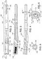
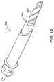
- FIG. 19shows one implementation of a tool 300 for preparing a medullary canal.
- the toolhas a drill bit 302 for reaming and also a mortise chisel 304.
- the drill bit 302reams out the medullary canal of the femur and the mortise chisel 304 cuts out a larger section in the more proximal end of a bone.
- the mortise chisel 304has an anatomically derived cross-section of approximately the same shape as the proximal section of the intramedullary nail.
- the mortise chisel 304may be of a wide variety of shapes, even complicated, asymmetrical shapes. This is advantageous because it enables a device and method for preparing voids able to accept a wide variety of shapes of intramedullary nails without merely over-reaming circular voids. Preparation of an accurately conforming void is valuable in avoiding unnecessary removal of healthy bone, and in ensuring stable seating of the nail.
- the tool 300is advanced as a unit, with the drill bit 302 reaming and the mortise chisel 304 cutting simultaneously.
- the drill bit 302may be turned with a power driver, or by hand.
- the entire tool 300may be advanced into a medullary canal manually, or advanced with the assistance of mechanical advantage or power equipment.
- the drill bit 302may be cannulated (not shown) such that the entire tool 300 is operable over and guided by a guide wire that has been inserted into the medullary canal.
- the bit for reamingis a more traditional reamer that is separate from a cutting tool such as the mortise chisel 304.
- the method for preparing a void in such an instancewould include first reaming an opening with a traditional reamer.
- a devicesuch as a chisel or a broach, shaped similar to the intramedullary nail to be implanted, would then be used to prepare the void.
- the chisel or broachmay be driven in by hand, with the assistance of a hammer or mallet, or with the use of other power equipment.
- a nail consistent with the void preparedwould then be implanted.
- a contoured broachor a custom router bit and template could be used as well.
- Broacheshave long been used to prepare openings for hip stems, and the use of a broach would be familiar to one of skill in the art.
- a router bit and templatecould be use, in effect, to mill out the desired shape in the bone. Such a method might also be used in combination with reaming or broaching to create the desired void.
- the intramedullary nails of the present disclosurecan be used to treat proximal femoral fractures and femoral shaft fractures, among other fractures of long bones.
- the intramedullary nailis secured in the femur by one or more fastening devices.
- the intramedullary nailis preferably used in conjunction with a proximal fastener assembly.
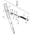
- FIGS. 20 and 21illustrate an intramedullary nail 100 used in conjunction with a fastener assembly 200.
- This type of fastener assemblymay be used in various other bones and to treat a number of other indications, but for the purpose of providing an example, it is described here in use with the proximal femur.
- the fastener assembly 200is useful in any situation where one fragment of a bone is to be drawn back toward or pushed away from another fragment of the bone in a controlled manner.
- the fastener assemblyprovides the additional advantage of being configurable to allow sliding of the assembly in a desired direction after the movement of the bone fragments has been accomplished.
- the axis of the proximal transverse aperture 118 in the intramedullary nail 100is angled relative to the proximal section 102 and, in use, is directed towards the femoral head.
- an engaging membersuch as a lag screw 202 is used in conjunction with a compression device, such as a compression screw 204 or a compression peg.
- the screwsare configured such that when in use the circumference of the lag screw 202 partially intersects with the circumference of the compression screw 204, so that the compression screw 204 nests partially within the circumference of the lag screw 202.
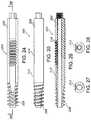
- This particular combination of lag screw 202 and compression screw 204are further illustrated in FIGS. 22 through 32 .
- the lag screw 202 shown in these figuresis intended to engage the femoral head and to slide in the transverse aperture 118 of the nail 100.
- the compression screw 204engages a shoulder 132 or other structure of the nail 100 within the transverse aperture 118 and also threads in the portion of lag screw 202 within which compression screw 204 nests, so that rotation of compression screw 204 controls sliding of the lag screw 202 relative to the nail 100 and thus compression of the femoral head against the fracture site.
- the lag screw 202 shown in these drawingsincludes an elongate body 206 and threaded end 208. As shown in FIGS. 24 and 25 , the threaded end 208 does not include a sharp end, which reduces the possibility of the cut out through the femoral head.
- the elongate body 206includes a channel 212 that allows for the positioning of the compression screw 204 partially inside the circumference of the lag screw 202.
- the channel 212includes a threaded portion 210 that compliments and cooperates with a threaded section 214 of the compression screw 204.
- the compression screw 204includes the threaded section 214 and a head section 215.
- the threaded section 214 of the compression screw 204is configured such that the threads are relatively flat and smooth at the exterior surface so that they can easily slide in the aperture and also reduce the possibility of cut out.
- the lag screw 202is received in the proximal transverse aperture 118 and into a pre-drilled hole in the femur so that the lag screw 202 extends across the fracture and into the femoral head.
- the threaded end 208 of the lag screw 202engages the femoral head as the lag screw 202 is rotated within aperture 118 causing its threaded end 208 to engage the femoral head.
- the threaded end 208may be any device for obtaining purchase in the femoral head, and includes but is not limited to, threads of any desired configuration including helices, barbs, blades, hooks, expanding devices, and the like.
- the placement depth of the lag screw 202 into the femoral headdiffers depending on the desired compression of the fracture.
- the compression screw 204can also be received through the proximal transverse aperture 118 into a predrilled hole in the femoral head.
- the threaded section 214 of the compression screw 204engages with the threaded portion of the channel 212 of the lag screw 202.
- the proximal transverse aperture 118includes the interior shoulder 132 ( FIG. 21 ) to limit the sliding of the compression screw 204 in the general medial direction and, therefore, to limit the sliding of the lag screw 202, through the aperture 118.
- the compression screw threads 214engage with the lag screw channel threaded portion 210 and the compression screw 204 moves in the generally medial direction down the lag screw 202.
- the head section 215 of the compression screw 204engages the shoulder 132 of the proximal transverse aperture 118 preventing the compression screw 204 from moving further in the general medial direction.
- the lag screw 202is drawn in the general lateral direction toward the intramedullary nail providing compression to the fracture.
- the compression screw 204partially intersecting the circumference of the lag screw 202 provides greater surface resistance and aids in the prevention of femoral head rotation.
- the compression screw 204therefore acts not only as a part of the mechanism for moving fragments of the fractured bone relative to one another, but also directly contacts bone of the femoral head to help prevent the femoral head from rotating about the axis of the lag screw 202.
- a set screw(not shown), positioned in the proximal end aperture 128 of the intramedullary nail, is used to engage the compression screw 204 and fix the compression screw 204 and lag screw 202 in place.
- the use of the set screw to fix the fastener assembly 200 in placeis fracture pattern dependent. If a set screw is not used to engage the fastener assembly, the fastener assembly 200 can slide within the proximal aperture limited by the shoulder 132.
- the diameter of the compression screw 204is smaller than the diameter of the lag screw 202.
- the diameters of the lag screw 202 and compression screw 204could be the same or the diameter of the lag screw 202 could be smaller than the diameter of the compression screw 204.
- the threads of the lag screw 202 and the compression screw 204could be a variety of different shapes as known to those skilled in the art.
- the purpose of the lag screw 202is to obtain purchase in bone, and the purpose of the compression screw 204 is to engage with and draw or move the lag screw. Any configuration that permits these functions is within the scope of the disclosure.
- the fastener assembly 200could additionally be configured to allow the addition of a prosthetic femoral head and neck.
- the lag screw 202would be replaced with a prosthetic head and neck.
- the neckwould fit into the proximal transverse aperture 118 in the nail 100.
- the designwould be beneficial where degeneration or re-injury of a repaired femoral fracture and hip joint later necessitated a total hip arthroplasty (THA).
- THAtotal hip arthroplasty
- the decision to accomplish a THAcould be made interoperatively, or after some period of time. Instead of having to prepare a femur to accept a hip stem as is known in association with THA, only a small portion of bone would need to be removed, along with the fastener assembly 200.
- the prosthetic head and neckcould then be inserted into the proximal transverse aperture 118, the acetabulum prepared, and the remainder of the THA completed.
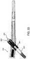
- FIG. 33is a cross-section view of an intramedullary nail 100 according to another implementation of the disclosure with an alternate fastener assembly 400.
- the fastener assembly 400 illustratedis very similar to the compressing fastener assembly of Smith & Nephew's IMHS® system, as is more thoroughly disclosed in U.S. Pat. No. 5,032,125 , which is hereby incorporated by reference, and various related international patents.
- the improvement of the device illustratedis that it includes the intramedullary nail 100 with an anatomically derived shape and its multiple advantages as discussed above.
- a sleeve 401fits through the intramedullary nail 100, and may be secured to the nail by set screw, or other effective mechanisms.
- a sliding lag screw 402is able to move axially within the sleeve 401.
- a compressing screw 404is threaded into the sliding lag screw 402 such that tightening of the compressing screw 404 draws the sliding lag screw 402 back into the sleeve 401. With this mechanism, a bone fragment may be brought into a desired position, but still permitted to achieve sliding compression once positioned.
- FIGS. 34-35illustrate a fastener assembly 200 according to another implementation of the disclosure having a lag screw 202 and a compression peg 502.
- the lag screw 202 and the compression peg 502are configured such that, when in use, the circumference of the lag screw 202 partially intersects with the circumference of the compression peg 502, although in some implementations the circumferences might be adjacent rather than intersecting.
- the lag screw 202includes an elongate body 206 and threaded end 208.
- the lag screw 202has a key 504 on the channel 212.
- the compression peg 502has a slot 503 that is adapted to receive the key 504 of the lag screw 202.
- the key 504 and slot 503can be a variety of complimentary shapes, such as, when considered in cross section, triangular, D-shaped, key-holed and other shapes as are apparent to those skilled in the art.
- the compression peg 502may be moved relative to the lag screw 202 by a compression tool (not shown) that applies disparate forces between the compression peg 502 and the lag screw 202, or between the entire assembly and the intramedullary nail 100.
- the lag screw 202is received to slide in a proximal aperture of the intramedullary nail so that the lag screw 202 extends across the break and into the femoral head.
- the threaded end 208 of the lag screw 202engages the femoral head.
- the compression peg 502helps to prevent the rotation of the femoral head on the lag screw 202.
- the compression peg 502is fixed in position in the intramedullary nail 100 by a set screw positioned in the proximal end aperture of the nail.
- the lag screw 202can slide on the compression peg 502 through the proximal aperture.
- the compression peg 502has barbs on its surface.
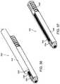
- a fastener assembly 200is illustrated in FIGS. 36-37 and has a compression peg 502 and a lag screw 202 similar to the implementation illustrated in FIGS. 34-35 except that the key 504 of the lag screw 202 and the slot 503 of the compression peg 502 have complimentary ratchet teeth 506.
- the compression peg 502is fixed in position in the intramedullary nail by a set screw positioned in the proximal end aperture. Compression of the fracture can be achieved by pulling the lag screw in the general lateral direction.
- the ratchet teeth 506allow the lag screw 202 to move in the general lateral direction, but prevent the lag screw 202 from moving in the general medial direction.
- a compression tool similar to the tool describe in association with FIGS. 34-35may be used to accomplish the movement.
- FIGS. 38-39illustrate a fastener assembly 200 having a lag screw 602, a cross hair screw 610 and a compression screw 604.
- the lag screw 602includes an elongate body 606 and threaded end 608.
- the elongate body 606is semi-circular shaped in cross section.
- the screws 602, 604, 610are configured so that the circumference of the lag screw 602 intersects with the circumferences of the cross hair screw 610 and the compression screw 604.
- the elongate body 606 of the lag screw 602is threaded to compliment and cooperate with a threaded section of the cross hair screw 610.
- the cross hair screw 610is threaded to engage with the lag screw 602 and the compression screw 604.
- the compression screw 604includes a threaded portion 614 and a head portion 612.
- the lag screw 602the cross hair screw 610 and the compression screw 604 are received simultaneously to slide in a proximal aperture of an intramedullary screw.
- the lag screw 602extends across the break and into the femoral head.
- the threaded end 608 of the lag screw 602engages the femoral head.
- the threads 614 of the compression screwengage the threads of the cross hair screw 610 and lag screw 602, thereby moving the lag screw 602 in the general lateral direction toward the intramedullary nail providing compression to the femoral head.
- the cross hair screw 610is then turned causing the compression screw 604 to move in the distal direction away from the lag screw 602.
- the fastener assembly 200can alternatively be configured so that the compression screw 604 moves proximally relative to the lag screw 602.
- the compression screw 604 separate from the lag screw 602helps to prevent rotation of the femoral head on the lag screw 602 by adding more area for resistance.
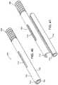
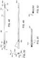
- FIGS. 40-41illustrate a fastener assembly 200 having a lag screw 702 and a compression peg 704.
- the lag screw 702includes an elongate body 706 and a threaded end 708.
- the elongate body 706is semi-circular shaped in order to allow the compression peg 704 to be positioned partially inside the circumference of the lag screw 702 for insertion into the femur and has a key 712 positioned on the interior side of the elongate body 706.
- the elongate body 706also has an aperture 710 through the body.
- the compression peg 704is generally cylindrical and is sized to fit within the semi-circular body 706 of the lag screw.
- the key 712 of the lag screwis received by a slot 714 in the compression peg 704.
- the key 712 and slot 714contain complimentary ratchet teeth.
- the lag screw 702 and the compression peg 704are received simultaneously to slide in a proximal aperture of an intramedullary screw into a pre-drilled hole in the femur.
- the lag screw 702extends across the break and into the femoral head.
- the threaded end of the lag screw 702engages the femoral head.
- a compression tool similar to the tool described in association with FIGS. 34-35may be used to accomplish movement between the compression peg 704 and the lag screw 702, or between the entire assembly and the intramedullary nail 100.
- a set screwmay used to fix the position of the fastener assembly.
- the set screwis configured such that when the set screw is tightened a protrusion on the set screw is received through the slot 710 of the lag screw 702 and moves the compression screw 704 away from the lag screw 702.
- the compression screw 704separate from the lag screw 702 helps to prevent rotation of the femoral head on the lag screw by adding more area for resistance.
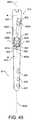
- FIG. 42illustrates another implementation where a fastener assembly 200 is employed in cooperation with a compression plate 150. As illustrated, the devices are being applied to a femur.
- the various implementations of the fastener assembly 200 disclosed abovemay be used with a similar compression plate, and various compression plates may be configured to be applicable to other parts of the anatomy.
- FIG. 43illustrates another implementation where a fastener assembly 200 is being used with a periarticular plate 170. The plate and fastener assembly shown are being applied to a proximal tibia.
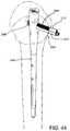
- FIG. 44illustrates another implementation where a fastener assembly 200 is used in combination with a humeral nail 190.
- a head section 212 of compression screw 204bears against the humerus to draw compression against the humerus.
- the compression force applied to lag screw 202, and the lag screw 202 affixed to a bone fragment through its threaded end 208the bone fragment may be drawn into position for proper healing.
- the opening in the humerusmay be enlarged such that head section 212 is permitted to penetrate the humerus and bear against a portion of the humeral nail 190.
- the fastener assembly 200would be shorter than illustrated in FIG. 45 to obtain purchase in the same area of bone with the threaded end 208.
- a universal femoral nail 800defines a reconstruction aperture 801 for treating fractures or other injury to the femoral head and neck in a reconstruction mode and targets the femoral head and neck, as described above, and an antegrade aperture 802 for treating fractures of the femoral shaft in an antegrade mode and targets the lesser trochanter.
- the nail 800includes a central long axis 800a, a head 800b formed at a proximal portion 812 of the nail 800 and a shaft 813 extending from the head 800b to a distal portion 814 of the nail 800.
- the cross-sectional shape of the head 800b in a plane perpendicular to the long axis 800ais generally non-circular.
- the cross-sectional shape of the head 800bis generally trapezoidal and includes rounded portions. For example, at least a portion of a lateral side 800d is flat. However, the medial side 800e is generally rounded.
- a medial to lateral plane M-Lbisects the head 800b, includes a central through axis 801a of the reconstruction aperture, and includes the central long axis 800a of the nail 800.
- the medial to lateral plane M-Lis coplanar with a coronal plane of the nail 800 that separates the front of the nail from the back of the nail.
- this planeis not necessarily related to a coronal plane of a patient's body or even a coronal plane of a patient's femur.
- the reconstruction aperture 801is not centrally disposed in the head 800b such that the medial to lateral plane M-L does not include the central through axis 801a, but the medial to lateral plane M-L is then parallel to a central through axis 801a of the reconstruction aperture 801, and parallel to the coronal plane of the nail 800.
- the reconstruction transverse aperture 801is "light bulb” shaped and oriented off the long axis 800a of the nail 800, and is configured to receive a lag member and a compression member, such as the lag screw 202 and the compression screw 204 described above.
- the central through axis 801a of the reconstruction aperture 801lies in the medial to lateral plane M-L, and is oriented at an angle A of about 122 degrees relative to the central long axis 800a.
- the antegrade transverse aperture 802is also oriented off the long axis 800a by an angle B, which is about 35 degrees.
- the antegrade aperture 802is oriented such that a central through axis 802a of the antegrade aperture 802 lies in an antegrade plane AP, which is parallel to the long axis 800a and is radially offset from the medial to lateral plane M-L by an angle C of approximately 12 degrees. As illustrated in FIG. 50 , the antegrade aperture 802 is not centered in the head 800b, such that the central through axis 802a of the antegrade aperture 802 does not intersect the long axis 800a of the nail 800. In some implementations, and as illustrated in FIG. 50 , the central through axis 802a intersects the medial to lateral plane M-L proximate the medial side 800e.
- the nail 800also includes three holes 831, 832, and 833 located in a distal section 814 of the nail that, in use, can receive pins or screws to stabilize the distal section of the nail 800.
- the most proximal hole 831is formed as a slot
- the central and most distal holes 832 and 833are formed as circular holes.
- the most proximal hole 831 and the most distal hole 833are formed such that respective central through axes 831a and 833a of the most proximal hole 831 and the most distal hole 833 lie in planes that are parallel to the antegrade plane AP.
- the central through axes 831a and 833aare radially offset from the medial to lateral plane M-L by the same angle as the central through axis 802c of the antegrade aperture 802.
- the antegrade aperture 802the most proximal hole 831 and the most distal hole 833 can be said to be parallel, or lie in parallel planes, even though they may be oriented differently with respect to the central axis 800a of the nail 800.
- the central through axis 802a of the antegrade aperture 802is oriented at 35 degrees with respect to the central long axis 800a of the nail 800.
- the most proximal hole 831 and the most distal hole 833may be formed at approximately 90 degrees to the central long axis 800a, or at other angular orientations.
- the central though axis 831a of the most proximal hole 831lies in the same plane as the central through axis 833a of the most distal hole 833.
- central through axes 831a and 833a of the most proximal hole 831 and the most distal hole 833can lie in the antegrade plane AP such that the central through axes 802a, 831a, and 833a are coplanar.
- a central through axis 832a of the central hole 832is also radially offset from the medial to lateral plane M-L.
- the central through axis 832ais offset from the medial to lateral plane M-L by a different amount than the central through axes 831a and 833a.
- the central through axis 832a of the central hole 832is offset from the medial to lateral plane M-L by 37 degrees, and is radially offset from the antegrade plane AP by 25 degrees.
- the nail 800When treating fractures of the neck, head, and intertrochanteric regions of the femur, the nail 800 is used in conjunction with first and second members, such as the lag screw 202 and the compression screw 204, received in the reconstruction aperture 801.
- first and second memberssuch as the lag screw 202 and the compression screw 204
- the nail 800When treating only a fracture in the femoral shaft, the nail 800 is used in conjunction with a bone pin received in the antegrade aperture 802.
- Running along the long axis 800a of the nail 800is a bore 816.
- a set screw(not shown) can be disposed in the bore 816 for locking the first and second members or the bone pin.
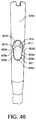
- the reconstruction aperture 801has a first semi-cylindrical aperture 810 associated with a first portion 811 ( FIG. 46 ) of the reconstruction aperture 801, and a second U-shaped aperture 820 associated with a second portion 821 ( FIG. 46 ) of the reconstruction aperture 801.
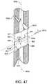
- the nail 800includes an inner wall 805 ( FIG. 47 ) that defines the reconstruction aperture 801.
- the inner wall 805includes a first, semi-cylindrical section 807 that defines the semi-cylindrical aperture 810 and a second, U-shaped section 809 that defines the U-shaped aperture 820.
- the reconstruction aperture 801has a constant cross-sectional shape along a length dimension, L, of the reconstruction aperture 801. Shoulder 803 is defined by an outward step 818 in the U-shaped section 809.
- the semi-cylindrical section 807 of the inner wall 805comprises an arc segment that extends more than 180 degrees, for example, 270 degrees, and terminates in two opposing edges 808a and 808b.
- the plane between the opposing edges 808a and 808bdefines a face 841 of the semi-cylindrical section 807.
- the opposing edges 808a and 808bare located at a transition, T, between the semi-cylindrical section 807 and the U-shaped section 809 of the inner wall 805.
- Ttransition
- the U-shaped section 809 of the inner wall 805includes a semi-cylindrical arc segment 809a opposite the face 841 of the semi-cylindrical section 807 and two mutually-opposing walls 809b and 809c extending from the semi-cylindrical arc segment 809a.
- the U-shaped section 809 of the inner wall 805also includes a face 845 defined by the plane between edges 809e and 809f of the walls 809b and 809c. As illustrated, the face 845 of the U-shaped section 809 is coplanar with the face 841 of the semi-cylindrical section 807.
- the semi-cylindrical arc segment 809aincludes a face 843 that opposes the face 841 of the semi-cylindrical section 807 of the inner wall 805 (and the face 845 of the U-shaped section 809 of the inner wall 805), and is spaced therefrom by the opposing walls 809b and 809c.
- the face 843 of the semi-cylindrical arc segment 809ais spaced from the first open face 841 of the first semi-cylindrical aperture 810 by a distance D such that a cylindrical member having a circular cross section of substantially the same diameter as the diameter of the semi-cylindrical arc segment 809a extends into the first portion 811 of the reconstruction aperture 801 when disposed in and abutting the semi-cylindrical arc segment 809a.
- the parallel walls 809b and 809cextend from the semi-cylindrical arc segment 809a (that is to say, from the face 843 of the semi-cylindrical arc segment 809a) the distance, D, which is less than the radius of the semi-cylindrical arc segment 809a.
- the diameter of the semi-cylindrical arc segment 809ais between about 5 millimeters and about 15 millimeters, and the amount of overlap of such a cylindrical member with a cylindrical member received within the semi-cylindrical section 807 is between about 1 millimeter and 5 millimeters.
- the opposing walls 809b and 809care parallel and the semi-cylindrical arc segment 809a is a 180 degree arc segment.
- the opposing walls 809b and 809ccan be divergent, and/or the semi-cylindrical arc segment 809a can be an arc segment less than 180 degrees.
- the memberwhen a member that is sized to fit within the semi-cylindrical arc segment 809a is disposed in the U-shaped aperture 820, the member is not constrained by a narrowing of the U-shaped aperture 820.
- a member that is sized to fit within the semi-cylindrical arc segment 809ais constrained from moving into the semi-cylindrical aperture 810 only when a second member is disposed in the semi-cylindrical aperture 810.
- a compression screw 204is disposed within the U-shaped section 809 of the inner wall 805 and a lag screw 202 is disposed within the semi-cylindrical section 807 of the inner wall 805
- the compression screw 204is constrained to remain in the U-shaped section 809, and the lag screw 202 and the compression screw 204 cooperate to resist a force moment applied to one or both of the lag screw 202 and the compression screw 204.
- the compression screw 204can move in response to forces applied to the compression screw 204, such that occurrence of bending or breaking of the compression screw 204 is reduced.
- the antegrade aperture 802includes a first opening (or entry) 802a formed in a lateral side 800d of the nail 800 that is proximal to a first opening (or entry) 801a of the reconstruction aperture 801 formed in the lateral side 800d of the nail 800.
- the first opening 801a of the reconstruction aperture 801is generally centered on the lateral side 800d of the nail 800 and the first opening 802a of the antegrade aperture 802 is not centered on the lateral side 800d of the nail 800.
- the non-circular cross-sectional shape of the head 800b with a larger lateral side 800d than medial side 800eprovides additional surface area for locating the first opening 802a of the antegrade aperture 802 off-center within the head 800b, and can provide increased strength compared to a head having a circular cross-sectional shape when the antegrade aperture 802 is oriented off the medial to lateral plane M-L.
- the reconstruction aperture 801is oriented in the direction of a femoral neck such that the second opening (or exit) 801b of the reconstruction aperture 801 formed in a medial side 800e of the nail 800 is proximal to the first opening 801a of the reconstruction aperture 801, the antegrade aperture 802 is oriented distally towards a second opening (or exit) 802b that is formed in the inner wall 805 at a location proximate to the second opening 801b of the reconstruction aperture 801 formed in the medial side 800e of the nail 800.
- the second opening 802b of the antegrade aperture 802can be formed in the medial side 800e of the nail 800, and the second opening 802b can be located proximally or distally of the second opening 801b of the reconstruction aperture 801,
- the exit opening 802bis formed on the medial side 800e of the nail 800 such that the exit opening 802b is contained entirely within the exit opening 801b of the reconstruction aperture 801.
- the co-location of the exit openings 802b and 801breduces an amount of material that is removed from the medial side 800e of the nail 800.
- the non-circular cross-sectional shape of the head 800ballows for the co-location of the exit openings 802b and 801b in conjunction with the radial offset of the antegrade plane AP and the medial to lateral plane M-L while maintaining structural strength of the head 800b.
- the head 800b of the nail 800is angled from the shaft 813 by an angle D, such as a 5 degree angle.
- the bendis formed in the antegrade plane AP such that a tangent of the long axis 800a at a location 831 in the head 800b makes an angle of approximately 5 degrees relative to a tangent of the long axis 800a at a location 833 in the shaft 813.
- the head 800b and the shaft 813are both generally straight in the antegrade plane AP.
- the nail 800is curved perpendicular to the antegrade plane AP such that the antegrade plane AP is also curved.
- the curve illustrated in FIG. 60is compound, having more than one radius of curvature perpendicular to the antegrade plane AP.
- the non-circular aperture of FIGS. 45-47is illustrated with circular semi-cylindrical portions
- the non-circular aperturecan have semi-cylindrical portions having other cross-sectional shapes, such as oval or rectangular.
- fastening members with corresponding shapesi.e., cylindrical fasteners having square, rectangular, oval, crescent, or other cross-sectional shapes can be used.
- the non-circular aperturemay have additional portions, which may or may not be cylindrical.
- one or more of the apertures 831, 832, 833 located near the distal end 800ccan be angled other than perpendicularly to the axis 800a having a first opening located proximally or distally of a second opening thereof.
- the cross-sectional shape of the shaft 813 in a plane perpendicular to the long axis 800ais substantially circular, although the diameter of the shaft 813 can be varied along the long axis 800a.
- all or a portion of the shaft 813can be tapered.
- the head 800bcan be formed in other cross-sectional shapes, including circular, oval, or polygonal, for example.
- the medial to lateral plane M-Lstill includes the central long axis 800a and is parallel to or includes the central through axis 801a of the reconstruction aperture 801.
- the transverse aperture 801can be oriented such that the angle A can be from about 110 degrees to about 150 degrees, or from about 120 degrees to about 130 degrees.
- the central through axis 832a of the central hole 832can be offset from the medial to lateral plane M-L and the antegrade plane AP by other amounts, such as by an angle from about 20 to about 75 degrees, or from about 30 degrees to about 60 degrees.
- the angle Ccan be from about 0 degrees to about 30 degrees, from about 0 degrees to about 20 degrees, or from about 10 degrees to about 15 degrees.
- the angle Dcan be from about 0 to about 20 degrees, or from about 0 to about 10 degrees.
- the central through axis 832a of the central hole 832can be radially offset from the antegrade plane by an angle from about 0 to about 90 degrees, or from about 0 to about 45 degrees.
Landscapes
- Health & Medical Sciences (AREA)
- Orthopedic Medicine & Surgery (AREA)
- Surgery (AREA)
- Life Sciences & Earth Sciences (AREA)
- Heart & Thoracic Surgery (AREA)
- Nuclear Medicine, Radiotherapy & Molecular Imaging (AREA)
- Engineering & Computer Science (AREA)
- Biomedical Technology (AREA)
- Neurology (AREA)
- Medical Informatics (AREA)
- Molecular Biology (AREA)
- Animal Behavior & Ethology (AREA)
- General Health & Medical Sciences (AREA)
- Public Health (AREA)
- Veterinary Medicine (AREA)
- Surgical Instruments (AREA)
- Prostheses (AREA)
Description
- This disclosure relates to orthopaedic implants and fastener assemblies.
- There are a variety of devices used to treat fractures of the femur, humerus, tibia, and other long bones. For example, fractures of the femoral neck, head, and intertrochanteric region have been successfully treated with a variety of compression screw assemblies, which include generally a compression plate having a barrel member, a lag screw and a compressing screw. Examples include the AMBI® and CLASSIC™ compression hip screw systems offered by Smith & Nephew, Inc. In such systems, the compression plate is secured to the exterior of the femur, and the barrel member is inserted in a predrilled hole in the direction of the femoral head. The lag screw has a threaded end, or another mechanism for engaging bone, and a smooth portion. The lag screw is inserted through the barrel member so that it extends across the break and into the femoral head. The threaded portion engages the femoral head. The compression screw connects the lag screw to the plate. By adjusting the tension of the compression screw, the compression (reduction) of the fracture can be varied. The smooth portion of the lag screw is free to slide through the barrel member to permit the adjustment of the compression screw. Some assemblies of the prior art use multiple screws to prevent rotation of the lag screw relative to the compression plate and barrel member and also to prevent rotation of the femoral head on the lag screw.
US2005/277936A1 discloses an intramedullary rod which includes multiple curved sections in different planes designed to conform with the long bones of a patient. - Intramedullary nails in combination with lag screws or other screw assemblies have been successfully used to treat fractures of the femur, humerus, tibia, and other long bones as well. A significant application of such devices has been the treatment of femoral fractures. One such nailing system is the IMHS® system offered by Smith & Nephew, Inc., and covered at least in part by
U.S. Pat. No. 5,032,125 and various related international patents. Other seminal patents in the field includeU.S. Pat. Nos. 4,827,917 ,5,167,663 ,5,312,406 , and5,562,666 , which are all assigned to Smith & Nephew, Inc. These patents are all hereby incorporated by reference. A typical prior art intramedullary nail may have one or more transverse apertures through its distal end to allow distal bone screws or pins to be screwed or otherwise inserted through the femur at the distal end of the intramedullary nail. This is called "locking" and secures the distal end of the intramedullary nail to the femur. In addition, a typical intramedullary nail may have one or more apertures through its proximal end to allow a lag screw assembly to be screwed or otherwise inserted through the proximal end of the intramedullary nail and into the femur. The lag screw is positioned across the break in the femur and an end portion of the lag screw engages the femoral head. An intramedullary nail can also be used to treat shaft fractures of the femur or other long bones. - As with compression hip screw systems, intramedullary nail systems are sometimes designed to allow compression screws and/or lag screws to slide through the nail and thus permit contact between or among the bone fragments. Contact resulting from sliding compression facilitates faster healing in some circumstances. In some systems, two separate screws (or one screw and a separate pin) are used in order, among other things, to prevent rotation of the femoral head relative to the remainder of the femur, to prevent penetration of a single screw beyond the femoral head, and to prevent a single screw from tearing through the femoral neck and head. When an additional screw or pin is used, however, unequal forces applied to the separated screws or pins can cause the separate screws or pins to be pressed against the sides of the holes through which the separate screws or pins are intended to slide. This may result in binding, which reduces the sliding of the screws or pins through the nail. Conversely, a problem can result from excessive compression of the femoral head toward or into the fracture site. In extreme cases, excessive sliding compression may cause the femoral head to be compressed all the way into the trochanteric region of the femur.
- One or both of a structure configured to be implanted in or stabilize a first bone fragment and a fastening assembly can be used to treat bone fractures. The structure may take the form of a plate or other device for at least partial application to the outer surface of bone, or an implant for at least partial implantation within bone. Such implants may include a proximal section having a transverse aperture, and an aperture substantially along their length. Preferably, they include at least one cross-section in their proximal portions which features a shape that imparts additional strength and resistance to tension. Such shapes can be provided, for instance, by (1) adding additional mass in lateral portions of the cross section, and/or (2) strategically adding and reducing mass in the cross section to take advantage of flange effects similar to the way flanges add structural benefits to I-beams and channels. One way to characterize such cross-sections, which can but need not be asymmetrical with respect to at least one axis, is that they generally feature a moment of inertia extending in a lateral direction from a point that is the midpoint of a line from a lateral tangent to a medial tangent of the cross section. In some structures, that line is coplanar with the axis of the transverse aperture and coplanar with the cross section and thus defined by the intersection of those planes. The endpoints of that line can be defined as the intersection of the line with tangents to the medial aspect and the lateral aspect of the cross section, respectively. Such implants also typically include a distal section and a transition section that provides a coupling between the proximal section and the distal section.
- Fastening assemblies can include an engaging member and a compression device. The fastening assemblies are adapted to be received in the transverse aperture of the implant in a sliding relationship, so that the fastening assembly is adapted to slide with respect to the transverse aperture, and thus apply compression to a fracture and for any other desired purpose. The engaging member is adapted to gain purchase in a second bone fragment. The engaging member and the compression device are configured so that the compression device interacts with a portion of the implant and also with a portion of the engaging member so that adjustment of the compression device controls sliding of the engaging member relative to the implant and thereby enables controlled movement between the first and second bone fragments. In some implementations, the compression device at least partially directly contacts the second bone fragment when implanted.
- In one general aspect, a femoral intramedullary nail includes a shaft having a proximal region, a distal region, a medial side, a lateral side, and a longitudinal axis extending proximally and distally, the proximal region having a non-circular cross-sectional shape perpendicular to the longitudinal axis. A reconstruction aperture is located in the proximal region for receiving two members in a reconstruction mode and the aperture is oriented to target the femoral head and neck. An antegrade aperture is located in the proximal region for receiving a member in an antegrade mode. The antegrade aperture is oriented to target the lesser trochanter. The reconstruction aperture extends from the medial side to the lateral of the nail and the antegrade aperture is radially offset from the reconstruction aperture. The antegrade aperture includes an exit opening located within the reconstruction aperture.
- Implementations can include one or more of the following features. For example, the reconstruction aperture comprises two overlapping apertures. The shaft comprises a head portion in the proximal region, the head portion having a cross-sectional shape perpendicular to the longitudinal axis that is different from a cross-sectional shape perpendicular to the longitudinal axis of the distal region of the shaft. The longitudinal axis within the head portion is angled from the longitudinal axis in the distal region.
- Also described but not claimed is a femoral intramedullary nail including a shaft having a proximal region, a distal region, a medial side, a lateral side, and a longitudinal axis extending proximally and distally. A reconstruction aperture is located in the proximal region for receiving two members in a reconstruction mode, and the reconstruction aperture is oriented to target the femoral head and neck. An antegrade aperture is located in the proximal region for receiving a member in an antegrade mode, and the antegrade aperture is oriented to target the lesser trochanter. A distal aperture is located in the distal region, and the reconstruction, antegrade, and distal apertures each have a central through axis. The central through axis of the antegrade aperture lies within an antegrade plane, with the antegrade plane being parallel to the longitudinal axis. The through axis of the distal aperture lies in the antegrade plane or a plane parallel to the antegrade plane, and the central through axis of the reconstruction aperture intersects the antegrade plane.
- Implementations can include one or more of the following features. For example, the reconstruction aperture composes two overlapping apertures. The reconstruction aperture comprises two discrete apertures. The shaft comprises a head portion in the proximal region, the head portion having a non-circular cross section perpendicular to the longitudinal axis. The longitudinal axis within the head portion is angled from the longitudinal axis in the distal region.
- Also described but not claimed is an intramedullary nail including a shaft having a proximal region, a distal region, a medial side, a lateral side, and a longitudinal axis extending proximally and distally. A reconstruction aperture is located in the proximal region for receiving two members in reconstruction mode, with the reconstruction aperture having an entry opening substantially on the lateral side of the shaft and an exit opening substantially on the medial side of the shaft. An antegrade aperture is located in the proximal region for receiving a member in an antegrade mode, with the antegrade aperture having an entry opening substantially on the lateral side of the shaft and an exit opening substantially on the medial side of the shaft. The antegrade aperture exit opening is contained entirely within the reconstruction aperture exit opening.
- Implementations can include one or more of the following features. For example, the reconstruction aperture comprises two overlapping apertures. The reconstruction aperture comprises two discrete apertures. The shaft composes a head portion in the proximal region, the head portion having a non-circular cross section perpendicular to the longitudinal axis. The longitudinal axis within the head portion is angled from the longitudinal axis in the distal region. A central through axis of the antegrade aperture intersects a plane that includes a central through axis of the reconstruction aperture.
- Also described but not claimed is an intramedullary nail including a first non-circular transverse aperture having a central through axis oriented off a central long axis of the nail, with the first transverse aperture including a shoulder and configured to receive a compression assembly. The first transverse aperture includes an entry on a lateral side of the nail and an exit on a medial side of the nail. A second transverse aperture has a central through axis oriented off the central long axis of the nail and has an entry on the lateral side of the nail and an exit on the medial side of the nail within the exit of the first transverse aperture. The central through axis of the second transverse aperture extends along an axis that is radially-offset from the central through axis of the first transverse aperture.
- Implementations can include one or more of the following features. For example, the first transverse aperture and the second transverse aperture are located in a head, and a third transverse aperture is located proximate a distal end of the nail. The head is angled relative to the long axis. A bore extends in a direction of the long axis, with the bore intersecting the first transverse aperture.
- Also described but not claimed is an orthopaedic implant including a nail having a long axis, an inner wall defining a through hole oriented off the long axis, and a first transverse aperture proximal of the through hole. The inner wall includes a first semi-cylindrical section having an arc greater than 180 degrees and defines a first portion of the through hole. A second U-shaped section has a pair of parallel walls and a semi-cylindrical segment having an arc of approximately 180 degrees. The second U-shape section defines a second portion of the through hole. The arc of the first semi-cylindrical section defines a first open face of the first portion of the through hole, and the parallel walls of the second U-shape portion define a second open face of the second portion of the through hole opposing the first open face, such that a cylindrical member of substantially the same diameter as that of the second semi-cylindrical section can pass out from the second portion of the through hole toward the first portion of the through hole.
- Implementations can include one or more of the following features. For example, the first transverse aperture has an exit located in the inner wall. The first transverse aperture extends along an axis that is radially-offset from the orientation of the through hole. The nail further comprises a second transverse aperture located proximate a distal end of the nail. The second transverse aperture extends along an axis that is non- perpendicular to the long axis of the nail. The first transverse aperture is oriented off the long axis and has an entry located in a head of the nail, the head of the nail being angled relative to the long axis of the nail. A second transverse aperture is located proximate a distal end of the nail, the second transverse aperture having an opening aligned with the entry of the first proximal aperture.
FIG. 1 is a perspective view of an intramedullary shown installed in a femur.FIG. 1A is a perspective view of an intramedullary nail in greater detail.FIG. 1B is a perspective view of an intramedullary nail.FIG. 1C is a cross-sectional view of a portion of the nail ofFig. 1B .FIG. 1D is a perspective view of an intramedullary nail.FIG. 2 is an elevation view of the intramedullary nail ofFIG. 1 .FIG. 3 is a cross-section view of the intramedullary nail ofFIG. 2 taken through the line 3-3.FIG. 4 is a side view of the intramedullary nail ofFIG. 2 .FIG. 5 is a cross-section view of the intramedullary nail ofFIG. 4 taken through the line 5-5.FIG. 6 is a cross-section of the intramedullary nail ofFIG. 4 taken through the line 6-6.FIGS. 7-12 are perspective views of intramedullary nails.FIG. 13 is a cross-section view of the intramedullary nail ofFIG. 7 taken through line 13-13.FIG. 14 is a cross-section view of the intramedullary nail ofFIG. 8 taken through line 14-14.FIG. 15 is a cross-section view of the intramedullary nail ofFIG. 9 taken through line 15-15.FIG. 16 is a cross-section view of the intramedullary nail ofFIG. 10 taken through line 16-16.FIG. 17 is a cross-section view of the intramedullary nail ofFIG. 11 taken through line 17-17.FIG. 18 is a cross-section view of the intramedullary nail ofFIG. 12 taken through line 18-18.FIG. 19 is a perspective view of a tool for preparing bone to receive certain devices.FIG. 20 is a perspective view of a device which includes a version of a fastener assembly.FIG. 21 is an exploded view of the intramedullary device and fastener assembly shown inFIG. 20 .FIG. 22 is a perspective view of the fastener assembly shown inFIG. 20 .FIG. 23 is an exploded view of the fastener assembly ofFIG. 20 .FIG. 24 is an elevation view of the engaging member of the fastener assembly ofFIG. 23 .FIG. 25 is a side view of the engaging member ofFIG. 24 .FIG. 26 is a cross-section view of the engaging member ofFIG. 24 taken through line 26-26.FIG. 27 is an end view of one end of the engaging member ofFIG. 24 .FIG. 28 is an end view of the other end of the engaging member ofFIG. 24 .FIG. 29 is an elevation view of the compression device of the fastener assembly ofFIG. 22 .FIG. 30 is a cross-section view of the compression device ofFIG. 29 shown through line 30-30.FIG. 31 is an end view of one end of the compression device ofFIG. 29 .FIG. 32 is an end view of the other end of the compression device ofFIG. 29 .FIG. 33 is a cross-section view of an intramedullary nail and screw assembly.FIG. 34 is a perspective view of a fastener assembly.FIG. 35 is a perspective view of the lag screw of the fastener assembly ofFIG. 34 .FIG. 36 is a perspective view of a fastener assembly.FIG. 37 is a perspective view of the lag screw of the fastener assembly ofFIG. 36 .FIG. 38 is a perspective view of a fastener assembly.FIG. 39 is an exploded view of the fastener assembly ofFIG. 38 .FIG. 40 is a perspective view of a fastener assembly.FIG. 41 is an exploded view of the fastener assembly ofFIG. 40 .FIG. 42 is a perspective view of a compression plate which includes a fastener assembly.FIG. 43 is a perspective view of a periarticular plate which includes a fastener assembly.FIG. 44 is a perspective view of a device used in the context of humeral repair in a shoulder joint.FIG. 45 is a perspective view showing a lateral side of an intramedullary nail.FIG. 46 is a perspective view showing a medial side of the intramedullary nail ofFIG. 45 .FIG. 47 is a cross-sectional view of the intramedullary nail ofFIG. 45 , taken along line 47-47.FIG. 48 is a plan view of a lateral side of an intramedullary nail.FIG. 49 is side plan view of the intramedullary nail ofFIG. 48 .FIG. 50 is a proximal end view of the intramedullary nail ofFIG. 47 .FIG. 51 is a cross-sectional view of the intramedullary nail taken along lines A-A ofFIG 48 in the M-L plane ofFIG. 50 .FIG. 52 is a cross-sectional view of the intramedullary nail taken along the AP plane ofFIG. 50 .FIG. 53 is side plan view of the intramedullary nail ofFIG. 47 perpendicular to the AP plane ofFIG. 50 .FIG. 54 is a plan view of the lateral side of the distal end of the intramedullary nail taken along lines M-M ofFIG. 53 .FIG. 55 is a cross-sectional view of the intramedullary nail taken along lines O-O ofFIG. 54 .FIG. 56 is a cross-sectional view of the intramedullary nail taken along lines P-P ofFIG. 54 .FIG. 57 is a cross-sectional view of the intramedullary nail taken along lines S-S ofFIG. 54 .FIG. 58 is a side view of the intramedullary nail ofFIGS. 47-57 perpendicular to the AP plane ofFIG, 50 including bends.FIG. 59 is an end view of the intramedullary nail ofFIG. 58 .FIG. 60 is a plan view of the lateral side of the nail ofFIG. 58 .- Methods, devices and systems according to implementations of this disclosure seek to provide improved treatment of femur fractures.
FIGS. 1-6 illustrate various views of one implementation of anintramedullary nail 100. Theintramedullary nail 100 has alongitudinal bore 130 throughout to aid in insertion in the bone. Theintramedullary nail 100 has aproximal section 102, atransition section 104, and adistal section 106. - The
proximal section 102 of the particular structure shown inFIGS. 1-6 preferably features an anatomically inspired shape that corresponds more accurately to typical cortical bone. One version of such shape is shown in the cross-sectional view of theproximal section 102 inFIG. 6 . The particular cross-section of theproximal section 102 shown inFIG. 6 is generally non-circular and exists along at least some portions of the length of theintramedullary nail 100. The cross-section ofFIG. 6 has a lateral side oraspect 108 that is larger than a medial side oraspect 109. Thelateral side 108 andmedial side 109 are joined by afirst side 110 and asecond side 116. At the intersection of thefirst side 110 with thelateral side 108 is a firstradiused corner 112 and at the intersection of thesecond side 116 with thelateral side 108 is a secondradiused corner 114. Thefirst side 110,second side 116 andlateral side 108 are of approximately equal length. Thefirst side 110 andsecond side 116 are oriented at acute angles relative to thelateral side 108, so that themedial side 109 is smaller than thelateral side 108. By having thelateral side 108 larger than themedial side 109 the rotational stability of theintramedullary nail 100 is increased, and resistance to bending and twisting can also be enhanced. - The
medial side 109 shown inFIG. 6 can be radiused. As can be seen inFIG. 4 , the radiusedmedial side 109 protrudes out from thetransition section 104 and continues to the proximal end of theintramedullary nail 100. The protrusion of themedial side 109 corresponds to the calcar region of the femur and improves the evenness of load distribution between the bone andintramedullary nail 100. - Furthermore, the general cross-section geometry of the
proximal section 102 reduces peak stresses in theproximal section 102. More specifically, the typical failure mode of an intramedullary nail and screw assembly combination is failure of the nail in tension on its lateral side. The tension is created by bending moment induced by body weight load that is applied to the screw assembly. Therefore, it would be beneficial in reducing stress in the proximal section of a nail to include more material on the side of the nail that is in tension, the lateral side, to shape the cross section more effectively to enhance strength and robustness in the lateral area, or both. The design illustrated inFIG. 6 accomplishes this objective. Thelateral side 108 is wider than themedial side 109, thus imparting, at least partially, a flange-like effect. Stress per unit area induced on thelateral side 108 is less than would be the case if the lateral side featured a smaller cross-sectional area, such as the cross-sectional area of themedial side 109. - A structure according to another implementation of the disclosure that benefits from the same principle is shown in
FIGS. 1B and 1C which illustrate anintramedullary nail 1100 with a generally circular cross section whose generallycircular aperture 1128 is disposed other than concentric with the periphery of the cross section. In the particular structure shown in these two figures, the offsetaperture 1128 is offset toward themedial side 1109 such that a greater portion of material is available to take load, and reduce stress, on thelateral side 1108. Likewise, any cross-section that provides more material on the lateral side of the section reduces stress per unit area in the nail on that side. - Regardless of the particular manner in which material or mass may be added to some portions of the lateral parts of the cross section of
proximal portion 102, material may be added and removed from some portions of the cross section in order to increase the strength and robustness of the lateral parts, or both, the effect can be characterized as imparting a moment of inertia to the cross section oriented at least partially in the direction of the lateral side oraspect 108. In a preferred implementation, the moment of inertia (shown denoted by the letter M onFIG. 6 ) can be characterized as extending in a lateral direction, or at least partially toward lateral aspect orside 108 from a point P that is the midpoint of a line L extending from the intersection I1 of that line with a tangent TI to thelateral aspect 108, to the intersection 12 of that line with a tangent T2 to themedial aspect 109. Stated another way, the effect in at least some cases is to create a cross section that features a moment of inertia extending in at least partially lateral direction from a center of the cross section. Preferably, that center can be a midpoint between the lateral and medial edges of the cross section. Alternatively, that center can be the center of mass of the cross section. The radius of gyration reflected by the moment of inertia, which is a function of the square of the distance of the incremental mass from the center, reflects additional strength in lateral parts of theproximal portion 102 caused by more mass or more strategically placed mass in the cross section. In some structures, line L is coplanar with the axis of thelongitudinal bore 130 and coplanar with the plane of the cross section and thus defined by the intersection of those planes. AsFIGS. 1A , on the one hand, and 1B and 1C on the other hand reflect, and bearing in mind that these are only two of a myriad of structures that can impart such lateral additional strength and robustness, the cross section can but need not be asymmetrical with respect to at least one of its axes. Additionally, thelongitudinal bore 130 can be located to share its central axis with a geometric center of the cross section, or it can be offset in order to help impart the lateral strength or for other purposes. - In the particular device shown in
FIGS. 1-6 , thefirst side 110,second side 116 andlateral side 108 have flat portions. Alternatively, these sides could be curved. In the implementations shown inFIGS. 1-6 , themedial side 109 is radiused, but as one skilled in the art could appreciate, the medial side could be flat or have one or more flat portions. - The
proximal section 102 has a proximaltransverse aperture 118 that receives a fastening or screw assembly 200 (various versions of which are shown inFIGS. 19-41 ) through theintramedullary nail 100. One implementation of the proximaltransverse aperture 118, shown inFIGS. 1-4 , is formed from two overlappingcircular apertures proximal circle aperture 120 is smaller in diameter than thedistal circle aperture 122. Theproximal circle aperture 120 shown has ashoulder 132 for constraining the insertion depth of the screw assembly as will be explained in more detail below. Various other apertures allowing insertion of various screw assemblies could be used as would be known to those skilled in the art. For example,FIG. 33 illustrates the intramedullary nail with a circular aperture. The implementation ofFIG. 33 is described in greater detail below.FIGS. 45 through 47 illustrate another non-circular aperture, which is described in greater detail below. - The
proximal section 102 illustrated inFIG. 3 has aproximal end aperture 128. Theproximal end aperture 128 is threaded to allow for the insertion of a set screw that can be used to fix the rotational and translational position of a screw assembly within the proximaltransverse aperture 118. A set screw may also include mechanisms for spanning a compression screw 204 (FIG. 19 ) and interfering with a lag screw 202 (FIG. 19 ) to independently restrict the rotation or translation of thelag screw 202. - As shown in
FIGS. 1-6 , thetransition section 104 is tapered from theproximal section 102 to thedistal section 106. The tapered nature of thetransition section 104 creates a press fit in the intramedullary canal that controls subsidence. The taperedtransition section 104 assists in preventing thenail 100 from being pressed further down into the intramedullary canal of the femur than intended. - In the implementation of the
intramedullary nail 100 shown inFIGS. 1-6 , the cross-section of thetransition section 104 is circular, but the cross-section could vary as known to those skilled in the art. The cross-section could be anatomically derived, similar to the cross-section of theproximal section 102, oval or non-circular. In the implementation shown inFIGS. 1-6 , thetransition section 104 contains a distaltransverse aperture 124. Thedistal aperture 124 allows the insertion through theintramedullary nail 100 of a distal locking screw for locking of theintramedullary nail 100. - The
distal section 106 of theintramedullary nail 100 is generally cylindrical and is configured to provide a reduced bending stiffness. The implementation shown inFIGS. 1-5 has alongitudinal slot 126 through the center of thedistal section 106 that forms twosides intramedullary nail 100 and reduces the chances of periprosthetic fractures. FIG. 1D shows anintramedullary nail 100 according to another implementation of the disclosure. This nail features, in its proximal portions, a noncircular cross section that is symmetrical with respect to its lateral - medial axis (in this case, preferably but not necessarily, oval shaped in cross-section), and which features a centered longitudinal bore (in this case, preferably but not necessarily, circular in cross-section). This nail achieves additional stability to the extent it resists twisting in the medullary canal. It also accomplishes the aim of placing more mass toward the lateral edge or aspect of the proximal cross section. Furthermore, it places additional mass toward the medial edge or aspect, and thus provides additional structure that acts as a fulcrum to decrease the mechanical advantage of the fastening assembly which when loaded is the component that imposes tensional stress on the lateral edge or aspect.FIGS. 7-18 illustrateintramedullary nails 100 according to other implementations of the disclosure.FIGS. 7 and13 illustrate anintramedullary nail 100 having no longitudinal bore throughout.FIGS. 8 and14 illustrate anintramedullary nail 100 havingstiffness reduction slots 140 in thetransition section 104 and thedistal section 106. Thestiffness reduction slots 140 reduce the bending stiffness at the distal end of theintramedullary nail 100 and could be used to receive locking screws in some implementations.FIGS. 9 and15 illustrate anintramedullary nail 100 having threelongitudinal slots 138 in thedistal section 106 and a portion of thetransition section 104 forming a cloverleaf pattern. This pattern more readily permits blood flow near theintramedullary nail 100 and also reduces bending stiffness at the distal end of thenail 100.FIGS. 10 and16 illustrate anintramedullary nail 100 in which thedistal section 106 and a portion of thetransition section 104 have a series oflongitudinal grooves 146. Thelongitudinal grooves 146 reduce bending stiffness at the distal end, provide rotational resistance, and enhance blood flow near theintramedullary nail 100.FIGS. 11 and17 illustrate anintramedullary nail 100 where thetransition section 104 and thedistal section 106 havefins 144. Thefins 144 provide rotational resistance for theintramedullary nail 100.FIGS. 12 and18 illustrate anintramedullary nail 100 havingbarbs 142 located on thedistal section 106 and a portion of thetransition section 104. Thebarbs 142 provide rotational resistance for theintramedullary nail 100.- Intramedullary nails according to the present disclosure may be inserted into a patient by any suitable known technique. Generally, the intramedullary canal of the bone is prepared with an appropriate tool to create a void for insertion of the nail. Some portions of the void may be prepared to be about 1 millimeter larger than the perimeter of the nail to permit sufficient space for blood flow after insertion of the nail. A guide pin or wire is optionally inserted into the prepared medullary canal. The nail is then introduced into the desired position. If the nail is cannulated, the nail can be introduced over the guide wire. The position of the nail may be confirmed by image intensification.
FIG. 19 shows one implementation of atool 300 for preparing a medullary canal. The tool has adrill bit 302 for reaming and also amortise chisel 304. In operation, thedrill bit 302 reams out the medullary canal of the femur and themortise chisel 304 cuts out a larger section in the more proximal end of a bone. As shown inFIG. 19 , themortise chisel 304 has an anatomically derived cross-section of approximately the same shape as the proximal section of the intramedullary nail. By applying this type of shaped, mortise chisel, the proximal end of the nail will be better enabled to seat on cortical bone that has been only minimally altered. Themortise chisel 304 may be of a wide variety of shapes, even complicated, asymmetrical shapes. This is advantageous because it enables a device and method for preparing voids able to accept a wide variety of shapes of intramedullary nails without merely over-reaming circular voids. Preparation of an accurately conforming void is valuable in avoiding unnecessary removal of healthy bone, and in ensuring stable seating of the nail.- In operation, the
tool 300 is advanced as a unit, with thedrill bit 302 reaming and themortise chisel 304 cutting simultaneously. Thedrill bit 302 may be turned with a power driver, or by hand. Likewise, theentire tool 300 may be advanced into a medullary canal manually, or advanced with the assistance of mechanical advantage or power equipment. In other configurations, thedrill bit 302 may be cannulated (not shown) such that theentire tool 300 is operable over and guided by a guide wire that has been inserted into the medullary canal. - In other implementations, the bit for reaming is a more traditional reamer that is separate from a cutting tool such as the
mortise chisel 304. The method for preparing a void in such an instance would include first reaming an opening with a traditional reamer. A device such as a chisel or a broach, shaped similar to the intramedullary nail to be implanted, would then be used to prepare the void. The chisel or broach may be driven in by hand, with the assistance of a hammer or mallet, or with the use of other power equipment. A nail consistent with the void prepared would then be implanted. - Other custom instruments such as a contoured broach or a custom router bit and template could be used as well. Broaches have long been used to prepare openings for hip stems, and the use of a broach would be familiar to one of skill in the art. A router bit and template could be use, in effect, to mill out the desired shape in the bone. Such a method might also be used in combination with reaming or broaching to create the desired void.
- The intramedullary nails of the present disclosure can be used to treat proximal femoral fractures and femoral shaft fractures, among other fractures of long bones. When used to treat femoral shaft fractures, the intramedullary nail is secured in the femur by one or more fastening devices. When used for the treatment of proximal femoral fractures the intramedullary nail is preferably used in conjunction with a proximal fastener assembly.
FIGS. 20 and21 illustrate anintramedullary nail 100 used in conjunction with afastener assembly 200. This type of fastener assembly may be used in various other bones and to treat a number of other indications, but for the purpose of providing an example, it is described here in use with the proximal femur. In general, thefastener assembly 200 is useful in any situation where one fragment of a bone is to be drawn back toward or pushed away from another fragment of the bone in a controlled manner. The fastener assembly provides the additional advantage of being configurable to allow sliding of the assembly in a desired direction after the movement of the bone fragments has been accomplished.- As shown in
FIG. 21 , the axis of the proximaltransverse aperture 118 in theintramedullary nail 100 is angled relative to theproximal section 102 and, in use, is directed towards the femoral head. In this implementation of thefastener assembly 200, an engaging member such as alag screw 202 is used in conjunction with a compression device, such as acompression screw 204 or a compression peg. The screws are configured such that when in use the circumference of thelag screw 202 partially intersects with the circumference of thecompression screw 204, so that thecompression screw 204 nests partially within the circumference of thelag screw 202. This particular combination oflag screw 202 andcompression screw 204 are further illustrated inFIGS. 22 through 32 . Briefly, thelag screw 202 shown in these figures is intended to engage the femoral head and to slide in thetransverse aperture 118 of thenail 100. Thecompression screw 204 engages ashoulder 132 or other structure of thenail 100 within thetransverse aperture 118 and also threads in the portion oflag screw 202 within whichcompression screw 204 nests, so that rotation ofcompression screw 204 controls sliding of thelag screw 202 relative to thenail 100 and thus compression of the femoral head against the fracture site. - The
lag screw 202 shown in these drawings includes anelongate body 206 and threadedend 208. As shown inFIGS. 24 and 25 , the threadedend 208 does not include a sharp end, which reduces the possibility of the cut out through the femoral head. Theelongate body 206 includes achannel 212 that allows for the positioning of thecompression screw 204 partially inside the circumference of thelag screw 202. Thechannel 212 includes a threadedportion 210 that compliments and cooperates with a threadedsection 214 of thecompression screw 204. Thecompression screw 204 includes the threadedsection 214 and ahead section 215. The threadedsection 214 of thecompression screw 204 is configured such that the threads are relatively flat and smooth at the exterior surface so that they can easily slide in the aperture and also reduce the possibility of cut out. - The
lag screw 202 is received in the proximaltransverse aperture 118 and into a pre-drilled hole in the femur so that thelag screw 202 extends across the fracture and into the femoral head. The threadedend 208 of thelag screw 202 engages the femoral head as thelag screw 202 is rotated withinaperture 118 causing its threadedend 208 to engage the femoral head. The threadedend 208 may be any device for obtaining purchase in the femoral head, and includes but is not limited to, threads of any desired configuration including helices, barbs, blades, hooks, expanding devices, and the like. The placement depth of thelag screw 202 into the femoral head differs depending on the desired compression of the fracture. - The
compression screw 204 can also be received through the proximaltransverse aperture 118 into a predrilled hole in the femoral head. The threadedsection 214 of thecompression screw 204 engages with the threaded portion of thechannel 212 of thelag screw 202. The proximaltransverse aperture 118 includes the interior shoulder 132 (FIG. 21 ) to limit the sliding of thecompression screw 204 in the general medial direction and, therefore, to limit the sliding of thelag screw 202, through theaperture 118. When thecompression screw 204 is tightened, thecompression screw threads 214 engage with the lag screw channel threadedportion 210 and thecompression screw 204 moves in the generally medial direction down thelag screw 202. Thehead section 215 of thecompression screw 204 engages theshoulder 132 of the proximaltransverse aperture 118 preventing thecompression screw 204 from moving further in the general medial direction. As thecompression screw 204 is tightened, thelag screw 202 is drawn in the general lateral direction toward the intramedullary nail providing compression to the fracture. Thecompression screw 204 partially intersecting the circumference of thelag screw 202 provides greater surface resistance and aids in the prevention of femoral head rotation. Thecompression screw 204 therefore acts not only as a part of the mechanism for moving fragments of the fractured bone relative to one another, but also directly contacts bone of the femoral head to help prevent the femoral head from rotating about the axis of thelag screw 202. - In one implementation, a set screw (not shown), positioned in the
proximal end aperture 128 of the intramedullary nail, is used to engage thecompression screw 204 and fix thecompression screw 204 andlag screw 202 in place. The use of the set screw to fix thefastener assembly 200 in place is fracture pattern dependent. If a set screw is not used to engage the fastener assembly, thefastener assembly 200 can slide within the proximal aperture limited by theshoulder 132. - In the implementation of the lag screw and compression screw shown in
FIGS. 20-32 , the diameter of thecompression screw 204 is smaller than the diameter of thelag screw 202. The diameters of thelag screw 202 andcompression screw 204 could be the same or the diameter of thelag screw 202 could be smaller than the diameter of thecompression screw 204. The threads of thelag screw 202 and thecompression screw 204 could be a variety of different shapes as known to those skilled in the art. In general, the purpose of thelag screw 202 is to obtain purchase in bone, and the purpose of thecompression screw 204 is to engage with and draw or move the lag screw. Any configuration that permits these functions is within the scope of the disclosure. - The
fastener assembly 200 could additionally be configured to allow the addition of a prosthetic femoral head and neck. In such an implementation, thelag screw 202 would be replaced with a prosthetic head and neck. The neck would fit into the proximaltransverse aperture 118 in thenail 100. The design would be beneficial where degeneration or re-injury of a repaired femoral fracture and hip joint later necessitated a total hip arthroplasty (THA). The decision to accomplish a THA could be made interoperatively, or after some period of time. Instead of having to prepare a femur to accept a hip stem as is known in association with THA, only a small portion of bone would need to be removed, along with thefastener assembly 200. The prosthetic head and neck could then be inserted into the proximaltransverse aperture 118, the acetabulum prepared, and the remainder of the THA completed. FIG. 33 is a cross-section view of anintramedullary nail 100 according to another implementation of the disclosure with analternate fastener assembly 400. Thefastener assembly 400 illustrated is very similar to the compressing fastener assembly of Smith & Nephew's IMHS® system, as is more thoroughly disclosed inU.S. Pat. No. 5,032,125 , which is hereby incorporated by reference, and various related international patents. The improvement of the device illustrated is that it includes theintramedullary nail 100 with an anatomically derived shape and its multiple advantages as discussed above. In operation, asleeve 401 fits through theintramedullary nail 100, and may be secured to the nail by set screw, or other effective mechanisms. A slidinglag screw 402 is able to move axially within thesleeve 401. A compressingscrew 404 is threaded into the slidinglag screw 402 such that tightening of the compressingscrew 404 draws the slidinglag screw 402 back into thesleeve 401. With this mechanism, a bone fragment may be brought into a desired position, but still permitted to achieve sliding compression once positioned.FIGS. 34-35 illustrate afastener assembly 200 according to another implementation of the disclosure having alag screw 202 and acompression peg 502. As shown inFIG. 34 , thelag screw 202 and thecompression peg 502 are configured such that, when in use, the circumference of thelag screw 202 partially intersects with the circumference of thecompression peg 502, although in some implementations the circumferences might be adjacent rather than intersecting. Thelag screw 202 includes anelongate body 206 and threadedend 208. Thelag screw 202 has a key 504 on thechannel 212. Thecompression peg 502 has aslot 503 that is adapted to receive the key 504 of thelag screw 202. The key 504 and slot 503 can be a variety of complimentary shapes, such as, when considered in cross section, triangular, D-shaped, key-holed and other shapes as are apparent to those skilled in the art. In operation, thecompression peg 502 may be moved relative to thelag screw 202 by a compression tool (not shown) that applies disparate forces between thecompression peg 502 and thelag screw 202, or between the entire assembly and theintramedullary nail 100.- In the
fastener assembly 200 shown inFIGS. 34-35 , thelag screw 202 is received to slide in a proximal aperture of the intramedullary nail so that thelag screw 202 extends across the break and into the femoral head. The threadedend 208 of thelag screw 202 engages the femoral head. Once thelag screw 200 has been properly engaged with the femoral head, thecompression peg 502 is inserted in the proximal aperture into a predrilled hole in the femoral head, in order to prevent further rotation of thelag screw 202 as theslot 503 of thecompression peg 502 receives the key 504 of thelag screw 202. By providing more area for resistance, thecompression peg 502 helps to prevent the rotation of the femoral head on thelag screw 202. Thecompression peg 502 is fixed in position in theintramedullary nail 100 by a set screw positioned in the proximal end aperture of the nail. Thelag screw 202 can slide on thecompression peg 502 through the proximal aperture. In another implementation, thecompression peg 502 has barbs on its surface. - A
fastener assembly 200 according to another implementation of the disclosure is illustrated inFIGS. 36-37 and has acompression peg 502 and alag screw 202 similar to the implementation illustrated inFIGS. 34-35 except that the key 504 of thelag screw 202 and theslot 503 of thecompression peg 502 havecomplimentary ratchet teeth 506. Thecompression peg 502 is fixed in position in the intramedullary nail by a set screw positioned in the proximal end aperture. Compression of the fracture can be achieved by pulling the lag screw in the general lateral direction. Theratchet teeth 506 allow thelag screw 202 to move in the general lateral direction, but prevent thelag screw 202 from moving in the general medial direction. A compression tool similar to the tool describe in association withFIGS. 34-35 may be used to accomplish the movement. FIGS. 38-39 illustrate afastener assembly 200 having alag screw 602, across hair screw 610 and acompression screw 604. Thelag screw 602 includes anelongate body 606 and threadedend 608. Theelongate body 606 is semi-circular shaped in cross section. Thescrews lag screw 602 intersects with the circumferences of thecross hair screw 610 and thecompression screw 604. Theelongate body 606 of thelag screw 602 is threaded to compliment and cooperate with a threaded section of thecross hair screw 610. Thecross hair screw 610 is threaded to engage with thelag screw 602 and thecompression screw 604. Thecompression screw 604 includes a threadedportion 614 and ahead portion 612.- In the implementation of
FIGS. 38-39 , thelag screw 602, thecross hair screw 610 and thecompression screw 604 are received simultaneously to slide in a proximal aperture of an intramedullary screw. Thelag screw 602 extends across the break and into the femoral head. The threadedend 608 of thelag screw 602 engages the femoral head. Ascompression screw 604 is tightened, thethreads 614 of the compression screw engage the threads of thecross hair screw 610 andlag screw 602, thereby moving thelag screw 602 in the general lateral direction toward the intramedullary nail providing compression to the femoral head. Thecross hair screw 610 is then turned causing thecompression screw 604 to move in the distal direction away from thelag screw 602. Thefastener assembly 200 can alternatively be configured so that thecompression screw 604 moves proximally relative to thelag screw 602. Thecompression screw 604 separate from thelag screw 602 helps to prevent rotation of the femoral head on thelag screw 602 by adding more area for resistance. FIGS. 40-41 illustrate afastener assembly 200 having alag screw 702 and acompression peg 704. Thelag screw 702 includes anelongate body 706 and a threadedend 708. Theelongate body 706 is semi-circular shaped in order to allow thecompression peg 704 to be positioned partially inside the circumference of thelag screw 702 for insertion into the femur and has a key 712 positioned on the interior side of theelongate body 706. Theelongate body 706 also has anaperture 710 through the body. Thecompression peg 704 is generally cylindrical and is sized to fit within thesemi-circular body 706 of the lag screw. The key 712 of the lag screw is received by aslot 714 in thecompression peg 704. The key 712 and slot 714 contain complimentary ratchet teeth.- The
lag screw 702 and thecompression peg 704 are received simultaneously to slide in a proximal aperture of an intramedullary screw into a pre-drilled hole in the femur. Thelag screw 702 extends across the break and into the femoral head. The threaded end of thelag screw 702 engages the femoral head. A compression tool similar to the tool described in association withFIGS. 34-35 may be used to accomplish movement between thecompression peg 704 and thelag screw 702, or between the entire assembly and theintramedullary nail 100. A set screw may used to fix the position of the fastener assembly. The set screw is configured such that when the set screw is tightened a protrusion on the set screw is received through theslot 710 of thelag screw 702 and moves thecompression screw 704 away from thelag screw 702. Thecompression screw 704 separate from thelag screw 702 helps to prevent rotation of the femoral head on the lag screw by adding more area for resistance. FIG. 42 illustrates another implementation where afastener assembly 200 is employed in cooperation with acompression plate 150. As illustrated, the devices are being applied to a femur. The various implementations of thefastener assembly 200 disclosed above may be used with a similar compression plate, and various compression plates may be configured to be applicable to other parts of the anatomy. For example,FIG. 43 illustrates another implementation where afastener assembly 200 is being used with aperiarticular plate 170. The plate and fastener assembly shown are being applied to a proximal tibia.FIG. 44 illustrates another implementation where afastener assembly 200 is used in combination with ahumeral nail 190. As illustrated, ahead section 212 ofcompression screw 204 bears against the humerus to draw compression against the humerus. With the compression force applied to lagscrew 202, and thelag screw 202 affixed to a bone fragment through its threadedend 208, the bone fragment may be drawn into position for proper healing. In some circumstances, it may be advantageous to place a washer or bearing surface (not shown) between thehead section 212 and the humeral bone against which thehead section 212 compresses. In yet another variant, the opening in the humerus may be enlarged such thathead section 212 is permitted to penetrate the humerus and bear against a portion of thehumeral nail 190. In such an implementation, thefastener assembly 200 would be shorter than illustrated inFIG. 45 to obtain purchase in the same area of bone with the threadedend 208.- Referring to
FIGS. 45-47 , a universalfemoral nail 800 defines areconstruction aperture 801 for treating fractures or other injury to the femoral head and neck in a reconstruction mode and targets the femoral head and neck, as described above, and anantegrade aperture 802 for treating fractures of the femoral shaft in an antegrade mode and targets the lesser trochanter. Thenail 800 includes a centrallong axis 800a, ahead 800b formed at aproximal portion 812 of thenail 800 and ashaft 813 extending from thehead 800b to adistal portion 814 of thenail 800. The cross-sectional shape of thehead 800b in a plane perpendicular to thelong axis 800a is generally non-circular. As illustrated inFIG. 50 , the cross-sectional shape of thehead 800b is generally trapezoidal and includes rounded portions. For example, at least a portion of alateral side 800d is flat. However, themedial side 800e is generally rounded. As also illustrated inFIG. 50 , a medial to lateral plane M-L bisects thehead 800b, includes a central throughaxis 801a of the reconstruction aperture, and includes the centrallong axis 800a of thenail 800. Thus, as illustrated, the medial to lateral plane M-L is coplanar with a coronal plane of thenail 800 that separates the front of the nail from the back of the nail. It should be noted that this plane is not necessarily related to a coronal plane of a patient's body or even a coronal plane of a patient's femur. Additionally, in some implementations, thereconstruction aperture 801 is not centrally disposed in thehead 800b such that the medial to lateral plane M-L does not include the central throughaxis 801a, but the medial to lateral plane M-L is then parallel to a central throughaxis 801a of thereconstruction aperture 801, and parallel to the coronal plane of thenail 800. - The
reconstruction transverse aperture 801 is "light bulb" shaped and oriented off thelong axis 800a of thenail 800, and is configured to receive a lag member and a compression member, such as thelag screw 202 and thecompression screw 204 described above. To target the femoral head and neck in the reconstruction mode, the central throughaxis 801a of thereconstruction aperture 801 lies in the medial to lateral plane M-L, and is oriented at an angle A of about 122 degrees relative to the centrallong axis 800a. The antegradetransverse aperture 802 is also oriented off thelong axis 800a by an angle B, which is about 35 degrees. Theantegrade aperture 802 is oriented such that a central throughaxis 802a of theantegrade aperture 802 lies in an antegrade plane AP, which is parallel to thelong axis 800a and is radially offset from the medial to lateral plane M-L by an angle C of approximately 12 degrees. As illustrated inFIG. 50 , theantegrade aperture 802 is not centered in thehead 800b, such that the central throughaxis 802a of theantegrade aperture 802 does not intersect thelong axis 800a of thenail 800. In some implementations, and as illustrated inFIG. 50 , the central throughaxis 802a intersects the medial to lateral plane M-L proximate themedial side 800e. - As shown in
FIGS. 48 and 49 , thenail 800 also includes threeholes distal section 814 of the nail that, in use, can receive pins or screws to stabilize the distal section of thenail 800. The mostproximal hole 831 is formed as a slot, and the central and mostdistal holes holes - The most
proximal hole 831 and the mostdistal hole 833 are formed such that respective central throughaxes proximal hole 831 and the mostdistal hole 833 lie in planes that are parallel to the antegrade plane AP. In other words, the central throughaxes antegrade aperture 802. Thus, theantegrade aperture 802, the mostproximal hole 831 and the mostdistal hole 833 can be said to be parallel, or lie in parallel planes, even though they may be oriented differently with respect to thecentral axis 800a of thenail 800. For example, as discussed above, the central throughaxis 802a of theantegrade aperture 802 is oriented at 35 degrees with respect to the centrallong axis 800a of thenail 800. However, the mostproximal hole 831 and the mostdistal hole 833 may be formed at approximately 90 degrees to the centrallong axis 800a, or at other angular orientations. In some implementations, the central thoughaxis 831a of the mostproximal hole 831 lies in the same plane as the central throughaxis 833a of the mostdistal hole 833. Additionally, the central throughaxes proximal hole 831 and the mostdistal hole 833 can lie in the antegrade plane AP such that the central throughaxes - A central through
axis 832a of thecentral hole 832 is also radially offset from the medial to lateral plane M-L. However, the central throughaxis 832a is offset from the medial to lateral plane M-L by a different amount than the central throughaxes axis 832a of thecentral hole 832 is offset from the medial to lateral plane M-L by 37 degrees, and is radially offset from the antegrade plane AP by 25 degrees. - When treating fractures of the neck, head, and intertrochanteric regions of the femur, the
nail 800 is used in conjunction with first and second members, such as thelag screw 202 and thecompression screw 204, received in thereconstruction aperture 801. When treating only a fracture in the femoral shaft, thenail 800 is used in conjunction with a bone pin received in theantegrade aperture 802. Running along thelong axis 800a of thenail 800 is abore 816. A set screw (not shown) can be disposed in thebore 816 for locking the first and second members or the bone pin. - The
reconstruction aperture 801 has a firstsemi-cylindrical aperture 810 associated with a first portion 811 (FIG. 46 ) of thereconstruction aperture 801, and a secondU-shaped aperture 820 associated with a second portion 821 (FIG. 46 ) of thereconstruction aperture 801. Thenail 800 includes an inner wall 805 (FIG. 47 ) that defines thereconstruction aperture 801. Theinner wall 805 includes a first,semi-cylindrical section 807 that defines thesemi-cylindrical aperture 810 and a second,U-shaped section 809 that defines theU-shaped aperture 820. As shown, except for ashoulder 803, thereconstruction aperture 801 has a constant cross-sectional shape along a length dimension, L, of thereconstruction aperture 801.Shoulder 803 is defined by an outward step 818 in theU-shaped section 809. - The
semi-cylindrical section 807 of theinner wall 805 comprises an arc segment that extends more than 180 degrees, for example, 270 degrees, and terminates in two opposingedges edges face 841 of thesemi-cylindrical section 807. The opposingedges semi-cylindrical section 807 and theU-shaped section 809 of theinner wall 805. Thus, thesemi-cylindrical section 807 and theU-shaped section 809 define a continuous surface of thereconstruction aperture 801. - The
U-shaped section 809 of theinner wall 805 includes asemi-cylindrical arc segment 809a opposite theface 841 of thesemi-cylindrical section 807 and two mutually-opposingwalls semi-cylindrical arc segment 809a. TheU-shaped section 809 of theinner wall 805 also includes aface 845 defined by the plane betweenedges 809e and 809f of thewalls face 845 of theU-shaped section 809 is coplanar with theface 841 of thesemi-cylindrical section 807. Thesemi-cylindrical arc segment 809a includes aface 843 that opposes theface 841 of thesemi-cylindrical section 807 of the inner wall 805 (and theface 845 of theU-shaped section 809 of the inner wall 805), and is spaced therefrom by the opposingwalls - In some implementations, the
face 843 of thesemi-cylindrical arc segment 809a is spaced from the firstopen face 841 of the firstsemi-cylindrical aperture 810 by a distance D such that a cylindrical member having a circular cross section of substantially the same diameter as the diameter of thesemi-cylindrical arc segment 809a extends into thefirst portion 811 of thereconstruction aperture 801 when disposed in and abutting thesemi-cylindrical arc segment 809a. For example, where thesemi-cylindrical arc segment 809a is a 180 degree arc segment, theparallel walls semi-cylindrical arc segment 809a (that is to say, from theface 843 of thesemi-cylindrical arc segment 809a) the distance, D, which is less than the radius of thesemi-cylindrical arc segment 809a. In some implementations, the diameter of thesemi-cylindrical arc segment 809a is between about 5 millimeters and about 15 millimeters, and the amount of overlap of such a cylindrical member with a cylindrical member received within thesemi-cylindrical section 807 is between about 1 millimeter and 5 millimeters. - As illustrated, the opposing
walls semi-cylindrical arc segment 809a is a 180 degree arc segment. Alternatively, however, the opposingwalls semi-cylindrical arc segment 809a can be an arc segment less than 180 degrees. Thus, when a member that is sized to fit within thesemi-cylindrical arc segment 809a is disposed in theU-shaped aperture 820, the member is not constrained by a narrowing of theU-shaped aperture 820. As such, a member that is sized to fit within thesemi-cylindrical arc segment 809a is constrained from moving into thesemi-cylindrical aperture 810 only when a second member is disposed in thesemi-cylindrical aperture 810. For example, when acompression screw 204 is disposed within theU-shaped section 809 of theinner wall 805 and alag screw 202 is disposed within thesemi-cylindrical section 807 of theinner wall 805, thecompression screw 204 is constrained to remain in theU-shaped section 809, and thelag screw 202 and thecompression screw 204 cooperate to resist a force moment applied to one or both of thelag screw 202 and thecompression screw 204. However, if thelag screw 202 is not present within thesemi-cylindrical section 807 of theinner wall 805, then thecompression screw 204 can move in response to forces applied to thecompression screw 204, such that occurrence of bending or breaking of thecompression screw 204 is reduced. - Referring additionally to
FIGS. 48-52 , theantegrade aperture 802 includes a first opening (or entry) 802a formed in alateral side 800d of thenail 800 that is proximal to a first opening (or entry) 801a of thereconstruction aperture 801 formed in thelateral side 800d of thenail 800. Thefirst opening 801a of thereconstruction aperture 801 is generally centered on thelateral side 800d of thenail 800 and thefirst opening 802a of theantegrade aperture 802 is not centered on thelateral side 800d of thenail 800. The non-circular cross-sectional shape of thehead 800b with a largerlateral side 800d thanmedial side 800e provides additional surface area for locating thefirst opening 802a of theantegrade aperture 802 off-center within thehead 800b, and can provide increased strength compared to a head having a circular cross-sectional shape when theantegrade aperture 802 is oriented off the medial to lateral plane M-L. - Additionally, while the
reconstruction aperture 801 is oriented in the direction of a femoral neck such that the second opening (or exit) 801b of thereconstruction aperture 801 formed in amedial side 800e of thenail 800 is proximal to thefirst opening 801a of thereconstruction aperture 801, theantegrade aperture 802 is oriented distally towards a second opening (or exit) 802b that is formed in theinner wall 805 at a location proximate to thesecond opening 801b of thereconstruction aperture 801 formed in themedial side 800e of thenail 800. However, in some implementations, thesecond opening 802b of theantegrade aperture 802 can be formed in themedial side 800e of thenail 800, and thesecond opening 802b can be located proximally or distally of thesecond opening 801b of thereconstruction aperture 801, - As shown in
FIGS. 51 and 52 , theexit opening 802b is formed on themedial side 800e of thenail 800 such that theexit opening 802b is contained entirely within theexit opening 801b of thereconstruction aperture 801. For given dimensions of theantegrade aperture 802 and thereconstruction aperture 801, the co-location of theexit openings medial side 800e of thenail 800. As mentioned above, the non-circular cross-sectional shape of thehead 800b allows for the co-location of theexit openings head 800b. - In some implementations, as illustrated in
FIGS. 58 and 59 , thehead 800b of thenail 800 is angled from theshaft 813 by an angle D, such as a 5 degree angle. The bend is formed in the antegrade plane AP such that a tangent of thelong axis 800a at alocation 831 in thehead 800b makes an angle of approximately 5 degrees relative to a tangent of thelong axis 800a at alocation 833 in theshaft 813. As illustrated, thehead 800b and theshaft 813 are both generally straight in the antegrade plane AP. As illustrated inFIGS. 59 and 60 , thenail 800 is curved perpendicular to the antegrade plane AP such that the antegrade plane AP is also curved. The curve illustrated inFIG. 60 is compound, having more than one radius of curvature perpendicular to the antegrade plane AP. - As those skilled in the art will appreciate, the particular implementations described above and illustrated in the figures are provided for illustration, and various alterations may be made in the structure and materials of the illustrated implementations. For example, while the non-circular aperture of
FIGS. 45-47 is illustrated with circular semi-cylindrical portions, the non-circular aperture can have semi-cylindrical portions having other cross-sectional shapes, such as oval or rectangular. Accordingly, fastening members with corresponding shapes, i.e., cylindrical fasteners having square, rectangular, oval, crescent, or other cross-sectional shapes can be used. Furthermore, the non-circular aperture may have additional portions, which may or may not be cylindrical. Additionally, one or more of theapertures axis 800a having a first opening located proximally or distally of a second opening thereof. Furthermore, in general, the cross-sectional shape of theshaft 813 in a plane perpendicular to thelong axis 800a is substantially circular, although the diameter of theshaft 813 can be varied along thelong axis 800a. For example, all or a portion of theshaft 813 can be tapered. Also, thehead 800b can be formed in other cross-sectional shapes, including circular, oval, or polygonal, for example. However, where other shapes are selected for thehead 800b, the medial to lateral plane M-L still includes the centrallong axis 800a and is parallel to or includes the central throughaxis 801a of thereconstruction aperture 801. Additionally, thetransverse aperture 801 can be oriented such that the angle A can be from about 110 degrees to about 150 degrees, or from about 120 degrees to about 130 degrees. The central throughaxis 832a of thecentral hole 832 can be offset from the medial to lateral plane M-L and the antegrade plane AP by other amounts, such as by an angle from about 20 to about 75 degrees, or from about 30 degrees to about 60 degrees. The angle C can be from about 0 degrees to about 30 degrees, from about 0 degrees to about 20 degrees, or from about 10 degrees to about 15 degrees. The angle D can be from about 0 to about 20 degrees, or from about 0 to about 10 degrees. The central throughaxis 832a of thecentral hole 832 can be radially offset from the antegrade plane by an angle from about 0 to about 90 degrees, or from about 0 to about 45 degrees.
Claims (7)
- A femoral intramedullary nail (800), comprising:a shaft (813) having a proximal region (812), a distal region (814), a medial side, a lateral side, and a longitudinal axis extending proximally and distally, the proximal region (812) having a non-circular cross-sectional shape perpendicular to the longitudinal axis;a reconstruction aperture (801) locating in the proximal region (812) for receiving at least one member in a reconstruction mode, the aperture (801) oriented to target the femoral head and neck; andan antegrade aperture (802) in the proximal region (812) for receiving at least one member in an antegrade mode, the antegrade aperture (802) oriented to target the lesser trochanter;wherein the reconstruction aperture (801) extends from the medial side to the lateral side of the nail (800) and the antegrade aperture (802) is radially offset from the reconstruction aperture (801);characterised in that:
the antegrade aperture (802) includes an exit opening (802b) entirely located within the reconstruction aperture (801). - The intramedullary nail of claim 1, wherein the reconstruction aperture (801) comprises two overlapping apertures.
- The intramedullary nail of claim 1, wherein the reconstruction aperture (801) comprises two discrete apertures.
- The intramedullary nail of claim 1, wherein the shaft (813) comprises a head portion (800b) in the proximal region (812), the head portion (800b) having a non-circular cross section perpendicular to the longitudinal axis.
- The intramedullary nail of claim 1, wherein the longitudinal axis within the head portion (800b) is angled from the longitudinal axis in the distal region (814).
- The intramedullary nail of claim 1, wherein the shaft (813) comprises a head portion (800b) in the proximal region (812), the head portion (800b) having a cross-sectional shape perpendicular to the longitudinal axis that is different from a cross-sectional shape perpendicular to the longitudinal axis of the distal region (814) of the shaft (813).
- The intramedullary nail of claim 6, wherein the longitudinal axis within the head portion (800b) is angled from the longitudinal axis in the distal region (814).
Applications Claiming Priority (2)
| Application Number | Priority Date | Filing Date | Title |
|---|---|---|---|
| US22207809P | 2009-06-30 | 2009-06-30 | |
| PCT/US2010/040631WO2011002903A2 (en) | 2009-06-30 | 2010-06-30 | Orthopaedic implant and fastener assembly |
Publications (3)
| Publication Number | Publication Date |
|---|---|
| EP2448505A2 EP2448505A2 (en) | 2012-05-09 |
| EP2448505A4 EP2448505A4 (en) | 2014-11-26 |
| EP2448505B1true EP2448505B1 (en) | 2019-06-26 |
Family
ID=43411728
Family Applications (1)
| Application Number | Title | Priority Date | Filing Date |
|---|---|---|---|
| EP10794718.6AActiveEP2448505B1 (en) | 2009-06-30 | 2010-06-30 | Orthopaedic implant and fastener assembly |
Country Status (10)
| Country | Link |
|---|---|
| US (1) | US8834469B2 (en) |
| EP (1) | EP2448505B1 (en) |
| JP (2) | JP5801297B2 (en) |
| KR (1) | KR101743051B1 (en) |
| CN (2) | CN102639074B (en) |
| AU (2) | AU2010266297B2 (en) |
| BR (1) | BRPI1011556A2 (en) |
| CA (1) | CA2765376C (en) |
| RU (1) | RU2580978C2 (en) |
| WO (1) | WO2011002903A2 (en) |
Cited By (1)
| Publication number | Priority date | Publication date | Assignee | Title |
|---|---|---|---|---|
| WO2025078262A1 (en)* | 2023-10-12 | 2025-04-17 | Orthoxel Dac | An intramedullary nail system |
Families Citing this family (63)
| Publication number | Priority date | Publication date | Assignee | Title |
|---|---|---|---|---|
| CN101917915B (en) | 2007-11-26 | 2014-08-06 | 比德尔曼技术有限责任两合公司 | Nails and Osseosynthesis Kits for Heels |
| US20110046625A1 (en)* | 2008-05-07 | 2011-02-24 | Tornier | Surgical technique and apparatus for proximal humeral fracture repair |
| RU2557692C2 (en)* | 2009-11-10 | 2015-07-27 | Смит Энд Нефью, Инк. | Adjustment of bone compression |
| US10588647B2 (en) | 2010-03-01 | 2020-03-17 | Stryker European Holdings I, Llc | Computer assisted surgery system |
| BR112013020956B1 (en)* | 2011-02-14 | 2020-12-08 | Synthes Gmbh | bone fixation set |
| US9265541B2 (en) | 2011-10-28 | 2016-02-23 | Stryker Trauma Gmbh | Intramedullary nail locking hole arrangement |
| EP2586393B1 (en)* | 2011-10-28 | 2014-10-08 | Stryker Trauma GmbH | Locking hole arrangement |
| CN104519833B (en)* | 2011-11-30 | 2017-09-26 | 史密夫和内修有限公司 | Orthopedic implant with powered penetrating fixation slot |
| USD693470S1 (en)* | 2012-04-13 | 2013-11-12 | Lance Fagan | Nail for bone fracture fixation |
| US9427266B2 (en)* | 2012-04-16 | 2016-08-30 | DePuy Synthes Products, Inc. | Bump cut on hole edge |
| DE202012103384U1 (en)* | 2012-09-05 | 2012-09-24 | Signus Medizintechnik Gmbh | Pelvic ring implant |
| US10039606B2 (en) | 2012-09-27 | 2018-08-07 | Stryker European Holdings I, Llc | Rotational position determination |
| EP2732783B1 (en) | 2012-11-14 | 2016-04-27 | Biedermann Technologies GmbH & Co. KG | Bone nail for the heel |
| USD693929S1 (en)* | 2012-12-13 | 2013-11-19 | Orthopedic Designs North American, Inc. | Intramedullary tang actuator |
| DE102013005414A1 (en)* | 2013-03-28 | 2014-10-02 | Dietmar Wolter | Osteosynthesis system for the multidirectional, angularly stable treatment of fractures of long bones including an intramedullary nail and bone screws |
| CN103654933A (en)* | 2013-12-27 | 2014-03-26 | 杨鹏 | Acetabular anterior wall anatomical steel plate |
| US9839454B2 (en) | 2014-03-21 | 2017-12-12 | Biomet C.V. | Intramedullary device with compound fastener trajectories |
| JP6562595B2 (en)* | 2014-05-21 | 2019-08-21 | ディトマール・ヴォルター | Osteosynthesis system for multi-directional, angle-stable treatment of tubular fractures with intramedullary nails and bone screws |
| ES2701245T3 (en) | 2014-11-25 | 2019-02-21 | Swemac Innovation Ab | Intramedullary nail |
| US20220151664A1 (en)* | 2015-04-16 | 2022-05-19 | Texas Tech University System | Ankle (Tibio-Talar) Fusion Nail |
| US12011198B2 (en) | 2015-04-24 | 2024-06-18 | Biomet Manufacturing, Llc | Humeral nail |
| KR101722252B1 (en)* | 2016-03-18 | 2017-04-03 | 이동훈 | Intramedullary nail having an anti-tilting fuction |
| JP6204638B1 (en)* | 2016-04-25 | 2017-09-27 | 山田 郁史 | Fracture fixation device |
| US10695110B2 (en) | 2016-04-25 | 2020-06-30 | Sakae Tanaka | Internal fixator for bone fracture |
| WO2018042595A1 (en)* | 2016-09-01 | 2018-03-08 | 株式会社オーミック | Thighbone fixing tool |
| US10682168B2 (en) | 2016-09-15 | 2020-06-16 | Wright Medical Technology, Inc. | Intramedullary implant with proximal plate and method for its use |
| US11045242B2 (en) | 2016-09-22 | 2021-06-29 | Globus Medical, Inc. | Systems and methods for intramedullary nail implantation |
| US11083503B2 (en) | 2016-09-22 | 2021-08-10 | Globus Medical, Inc. | Systems and methods for intramedullary nail implantation |
| US10299847B2 (en) | 2016-09-22 | 2019-05-28 | Globus Medical, Inc. | Systems and methods for intramedullary nail implantation |
| US10751096B2 (en) | 2016-09-22 | 2020-08-25 | Bala Sundararajan | Systems and methods for intramedullary nail implantation |
| US10492803B2 (en) | 2016-09-22 | 2019-12-03 | Globus Medical, Inc. | Systems and methods for intramedullary nail implantation |
| MX2019004076A (en)* | 2016-10-10 | 2019-06-10 | Ferrero Manzanal Francisco | Intramedullary nailing system of variable angle to treat femur fractures. |
| RU2632706C1 (en)* | 2016-11-30 | 2017-10-09 | Олег Андреевич Стрелецкий | Method for anti-adhesive antibacterial coating application on orthopedic implants from titanium and stainless steel |
| CN106618719B (en)* | 2017-01-11 | 2023-04-18 | 海口市人民医院 | Hollow lag screw guide pin aiming fixer for reduction through posterior femoral lesser tuberosity |
| EP3585287B1 (en)* | 2017-02-27 | 2024-11-13 | Paragon 28, Inc. | Intramedullary nail fixation systems |
| CN107280749B (en)* | 2017-08-03 | 2023-06-16 | 大博医疗科技股份有限公司 | Blade structure, hip screw and femoral fracture treatment device |
| CN107320168A (en)* | 2017-08-03 | 2017-11-07 | 大博医疗科技股份有限公司 | Femur fixing device |
| US11446072B2 (en) | 2017-10-10 | 2022-09-20 | DePuy Synthes Products, Inc. | Self-retaining nail to insertion handle interface |
| MX2020003481A (en) | 2017-10-11 | 2020-12-07 | Howmedica Osteonics Corp | Humeral fixation plate guides. |
| US10881436B2 (en) | 2017-10-27 | 2021-01-05 | Wright Medical Technology, Inc. | Implant with intramedullary portion and offset extramedullary portion |
| CN107837120B (en)* | 2017-12-05 | 2024-07-12 | 苏州口腔医院(集团)有限公司 | Supporting nail capable of adjusting supporting wire tension |
| ES3034064T3 (en)* | 2018-04-13 | 2025-08-12 | Stryker European Operations Holdings Llc | Femoral nail with enhanced bone conforming geometry |
| CN108670502B (en)* | 2018-05-24 | 2021-05-11 | 大博医疗科技股份有限公司 | Femoral stem of femoral joint prosthesis and femoral joint prosthesis |
| KR102153796B1 (en) | 2018-10-16 | 2020-09-08 | 주식회사 아이키 | Intramedulary lod for bone joint |
| US11660201B2 (en) | 2018-10-25 | 2023-05-30 | Wright Medical Technology, Inc. | Systems, apparatuses, and methods for correcting a bone defect |
| CN109925040B (en)* | 2019-04-29 | 2024-06-18 | 大博医疗科技股份有限公司 | Intramedullary nail |
| US11633219B2 (en) | 2019-06-26 | 2023-04-25 | Globus Medical, Inc. | Fenestrated pedicle nail |
| US11285008B1 (en)* | 2019-11-08 | 2022-03-29 | Omnes Medical Inc. | Hip implant with compression resistance and self-centering features |
| JP7693964B2 (en)* | 2020-01-23 | 2025-06-18 | 株式会社シミズテック | Artificial hip stem |
| CN111281510A (en)* | 2020-02-27 | 2020-06-16 | 天津市威曼生物材料有限公司 | Combined anatomical intramedullary fixation device for proximal femur fracture |
| CN111281511A (en)* | 2020-02-27 | 2020-06-16 | 天津市威曼生物材料有限公司 | Anatomical proximal femoral intramedullary nail |
| CN111658109B (en)* | 2020-06-22 | 2025-01-14 | 常州市康辉医疗器械有限公司 | Main nail for intramedullary nail system and intramedullary nail system |
| CN112022321B (en)* | 2020-09-12 | 2024-10-11 | 陈聚伍 | Fracture composite structure fixing nail and fracture nail plate assembly |
| TR202017292A1 (en)* | 2020-10-30 | 2022-05-23 | Tst Rakor Ve Tibbi Aletler Sanayi Ve Ticaret Ltd Sirketi | ARTRODESIA NAIL |
| CN112353475B (en)* | 2020-11-06 | 2025-03-07 | 陈聚伍 | Femoral trochanteric fracture fixation device |
| CN113768599A (en)* | 2021-02-02 | 2021-12-10 | 浙江德康医疗器械有限公司 | Bone cement intramedullary nail fixing system |
| CN113576637A (en)* | 2021-08-19 | 2021-11-02 | 宁波兆盈医疗器械有限公司 | Femoral intramedullary nail device and use method and application thereof |
| US12004785B2 (en) | 2022-04-21 | 2024-06-11 | DePuy Synthes Products, Inc. | Retrograde femoral intramedullary nail, and related systems and methods |
| US20230338073A1 (en)* | 2022-04-26 | 2023-10-26 | Stryker European Operations Limited | Internal Brace Plate |
| KR102713912B1 (en)* | 2022-07-18 | 2024-10-11 | 주식회사 코렌텍 | Humeral Stem for Fractures |
| WO2024238198A1 (en)* | 2023-05-15 | 2024-11-21 | Smith & Nephew, Inc. | Orthopedic intramedullary nail system for greater trochanter fixation |
| US20250204963A1 (en)* | 2023-12-23 | 2025-06-26 | George J. Haidukewych | Interconnected implants and methods |
| WO2025193393A1 (en)* | 2024-03-15 | 2025-09-18 | Smith & Nephew, Inc. | Intramedullary femoral nail with a flexible distal end region |
Family Cites Families (200)
| Publication number | Priority date | Publication date | Assignee | Title |
|---|---|---|---|---|
| US2267925A (en) | 1941-02-11 | 1941-12-30 | Herbert A Johnston | Fracture securing apparatus |
| US2699774A (en) | 1952-05-12 | 1955-01-18 | Livingston Herman Harrison | Bone pin locking device |
| US3374786A (en) | 1964-12-15 | 1968-03-26 | George R. Callender Jr. | Fractured bone setting fastener assembly |
| US3630261A (en) | 1968-02-27 | 1971-12-28 | Rex Chainbelt Inc | Frictional antirotation device |
| US3530854A (en) | 1968-07-11 | 1970-09-29 | John Kearney | Fracture nail assembly |
| US3990438A (en) | 1975-04-21 | 1976-11-09 | Pritchard Rowland W | Bone fracture fixation and compression apparatus |
| US4103683A (en) | 1977-06-03 | 1978-08-01 | Neufeld John A | Sub-trochanteric nail |
| US4172452A (en) | 1978-05-15 | 1979-10-30 | Howmedica, Inc. | Fracture nail plate assembly |
| CH648197A5 (en) | 1980-05-28 | 1985-03-15 | Synthes Ag | IMPLANT AND SCREW FASTENING ON ITS BONE. |
| US4438762A (en) | 1981-12-30 | 1984-03-27 | Richard F. Kyle | Orthopedic hip fixation device |
| US4641640A (en) | 1982-01-18 | 1987-02-10 | Calvin Griggs | Compression screw assembly |
| US4432358A (en) | 1982-01-22 | 1984-02-21 | Fixel Irving E | Compression hip screw apparatus |
| US4657001A (en) | 1984-07-25 | 1987-04-14 | Fixel Irving E | Antirotational hip screw |
| US4612920A (en) | 1984-11-06 | 1986-09-23 | Zimmer, Inc. | Compression hip screw |
| US4622959A (en)* | 1985-03-05 | 1986-11-18 | Marcus Randall E | Multi-use femoral intramedullary nail |
| US4621629A (en) | 1985-08-12 | 1986-11-11 | Harrington Arthritis Research Center | Compression hip screw |
| US5190544A (en) | 1986-06-23 | 1993-03-02 | Pfizer Hospital Products Group, Inc. | Modular femoral fixation system |
| US4776330A (en) | 1986-06-23 | 1988-10-11 | Pfizer Hospital Products Group, Inc. | Modular femoral fixation system |
| DE8620399U1 (en) | 1986-07-30 | 1986-10-09 | Howmedica GmbH Werk Schönkirchen, 2314 Schönkirchen | Osteosynthesis aids for the treatment of subtrochanteric fractures |
| US5312406A (en) | 1986-12-30 | 1994-05-17 | Smith & Nephew Richards Inc. | Method of treating an intertrochanteric fracture |
| US5167663A (en) | 1986-12-30 | 1992-12-01 | Smith & Nephew Richards Inc. | Femoral fracture device |
| US4827917A (en) | 1986-12-30 | 1989-05-09 | Richards Medical Company | Fermoral fracture device |
| GB8722370D0 (en) | 1987-09-23 | 1987-10-28 | Halder S C | Fixating device |
| US5176681A (en) | 1987-12-14 | 1993-01-05 | Howmedica International Inc. | Intramedullary intertrochanteric fracture fixation appliance and fitting device |
| EP0355411A1 (en) | 1988-08-10 | 1990-02-28 | Ace Medical Company | Intramedullary rod for femur stabilization |
| DE8900121U1 (en) | 1989-01-04 | 1990-02-15 | Mecron Medizinische Produkte Gmbh, 1000 Berlin | Compression screw connection device |
| US4978349A (en) | 1989-08-03 | 1990-12-18 | Synthes (U.S.A.) | Fixation plate |
| US5032125A (en) | 1990-02-06 | 1991-07-16 | Smith & Nephew Richards Inc. | Intramedullary hip screw |
| US5112333A (en) | 1990-02-07 | 1992-05-12 | Fixel Irving E | Intramedullary nail |
| US5041116A (en) | 1990-05-21 | 1991-08-20 | Wilson James T | Compression hip screw system |
| US5122141A (en) | 1990-08-30 | 1992-06-16 | Zimmer, Inc. | Modular intramedullary nail |
| US5100404A (en) | 1990-09-04 | 1992-03-31 | Beth Israel Hospital | Intramedullary nailing method and apparatus |
| US5514138A (en) | 1991-02-08 | 1996-05-07 | Pfizer Inc. | Connector having a stop member |
| GB9113578D0 (en) | 1991-06-24 | 1991-08-14 | Howmedica | Intramedullary intertrochanteric fracture fixation appliance |
| DE9109883U1 (en) | 1991-08-09 | 1991-09-26 | Howmedica GmbH, 2314 Schönkirchen | Locking nail for the treatment of femoral fractures in the middle and trochanteric region |
| CH686339A5 (en) | 1991-12-10 | 1996-03-15 | Synthes Ag | Nut for the plate fixation. |
| IT1257628B (en) | 1992-01-14 | 1996-02-01 | ENDOMIDOLLAR NAIL FOR DYNAMIC OSTEOSYNTHESIS WITH A DISTAL SELF-LOCKING END FOR FRACTURES OF THE FEMORAL TROCANTERIC REGION | |
| DE4318150C2 (en) | 1993-06-01 | 1996-08-01 | Endocare Ag | Osteosynthesis tools for the treatment of subtrochanteric and pertrochanteric fractures as well as fractures of the femoral neck |
| IT1257859B (en) | 1992-07-13 | 1996-02-13 | ENDOPROTESIS FOR OSTEOSYNTHESIS OF THE PROXIMAL FEMOR | |
| FR2698261B1 (en) | 1992-11-24 | 1995-03-17 | Lacaffiniere Jean Yves De | Device for guiding a double screw of the neck of the femur for locked trochantero-diaphyseal nail. |
| US5429640A (en) | 1992-11-27 | 1995-07-04 | Clemson University | Intramedullary rod for fracture fixation of femoral shaft independent of ipsilateral femoral neck fracture fixation |
| WO1994013219A1 (en) | 1992-12-04 | 1994-06-23 | Frigg, Robert | Modular marrow nail |
| US5364399A (en) | 1993-02-05 | 1994-11-15 | Danek Medical, Inc. | Anterior cervical plating system |
| US5324292A (en) | 1993-02-10 | 1994-06-28 | Zimmer, Inc. | Fracture fixation assembly with selectively removable protrusion |
| IL105183A (en) | 1993-03-28 | 1996-07-23 | Yehiel Gotfried | Surgical device for connection of fractured bones |
| IL109929A (en) | 1994-06-08 | 1998-04-05 | Gotfried Yehiel | Surgical instrument for use during connection of a fractured bone |
| IT1272537B (en) | 1993-08-30 | 1997-06-23 | Synos Medical Spa | ENDOMIDOLLAR NAIL FOR THE SYNTHESIS OF THE PROXIMAL FEMORE FRACTURES AND EQUIPMENT FOR ITS POSITIONING |
| FR2711505B1 (en) | 1993-10-25 | 1995-12-29 | Tornier Sa | Device for synthesizing fractures of the upper end of the femur. |
| US5514137A (en) | 1993-12-06 | 1996-05-07 | Coutts; Richard D. | Fixation of orthopedic devices |
| FR2717674B1 (en) | 1994-03-23 | 1996-06-28 | Smith & Nephew Richards France | Osteosynthesis device for femoral neck fractures and instrument for actuating this device. |
| FR2718013B1 (en) | 1994-04-01 | 1996-06-07 | Medinov Sa | Central medullary nailing device especially for sub-cervical fractures of the femur. |
| US5855579A (en) | 1994-07-15 | 1999-01-05 | Smith & Nephew, Inc. | Cannulated modular intramedullary nail |
| US5549610A (en)* | 1994-10-31 | 1996-08-27 | Smith & Nephew Richards Inc. | Femoral intramedullary nail |
| JP3077049B2 (en) | 1994-11-01 | 2000-08-14 | 有限会社エーアンドエフ | Internal fixation member for treatment of rotational femoral head osteotomy and femoral neck fracture |
| DK0715832T3 (en) | 1994-11-17 | 2002-04-22 | Treu Instr Gmbh | Marrow seam for hip compression |
| US5888204A (en) | 1996-04-15 | 1999-03-30 | Fastenetix, Llc | Acetabular cup having capped polyaxial locking screws |
| FR2737968B1 (en) | 1995-08-23 | 1997-12-05 | Biomat | IMPLANT FOR OSTEOSYNTHESIS OF SUPERIOR FEMALE EPIPHYSIS |
| JP3307805B2 (en) | 1995-08-31 | 2002-07-24 | 瑞穂医科工業株式会社 | Intramedullary nail |
| JPH0966061A (en) | 1995-08-31 | 1997-03-11 | Mizuho Ika Kogyo Kk | Intramedullary nail |
| AU6971396A (en) | 1995-09-08 | 1997-03-27 | Depuy Ace Medical Company | Internal bone fracture fixator |
| US5749872A (en) | 1995-09-08 | 1998-05-12 | Ace Medical Company | Keyed/keyless barrel for bone plates |
| FR2741256A1 (en) | 1995-11-21 | 1997-05-23 | Advanced Technical Fabrication | CENTROMEDULAR NAIL |
| US5984970A (en) | 1996-03-13 | 1999-11-16 | Bramlet; Dale G. | Arthroplasty joint assembly |
| US5976139A (en) | 1996-07-17 | 1999-11-02 | Bramlet; Dale G. | Surgical fastener assembly |
| US5658288A (en) | 1996-03-19 | 1997-08-19 | Kim; Andrew C. | Universal dynamic compression device for intramedullary system |
| US5779704A (en) | 1996-03-19 | 1998-07-14 | Kim; Andrew C. | Bi-directional universal dynamic compression device |
| US6087446A (en) | 1996-03-20 | 2000-07-11 | Hercules Incorporated | Masterbatch formulations for polyolefin applications |
| IT1287271B1 (en) | 1996-04-05 | 1998-08-04 | Antonio Chemello | ENDOMIDOLLAR NAIL FOR THE OSTEOSYNTHESIS OF LONG BONE FRACTURES |
| DE19619093B4 (en) | 1996-05-06 | 2004-02-26 | Aap Implantate Ag | Intramedullary nail system for fracture healing or bone extension |
| WO1998002105A1 (en) | 1996-07-17 | 1998-01-22 | Bramlet Dale G | Surgical fastener assembly |
| EP0917449B1 (en) | 1996-07-31 | 2003-02-05 | Synthes Ag Chur | Device for attaching fractured hip-joint heads |
| IT242435Y1 (en) | 1996-10-24 | 2001-06-14 | Hit Medica Srl | NAIL FOR THE REDUCTION OF TROCANTERIC FRACTURES AND OF THE NECK DELFEMORE. |
| US5741256A (en) | 1997-01-13 | 1998-04-21 | Synthes (U.S.A.) | Helical osteosynthetic implant |
| IT1293934B1 (en) | 1997-01-21 | 1999-03-11 | Orthofix Srl | ENDOMIDOLLAR NAIL FOR THE TREATMENT OF HIP FRACTURES |
| US6106528A (en) | 1997-02-11 | 2000-08-22 | Orthomatrix, Inc. | Modular intramedullary fixation system and insertion instrumentation |
| ES2297092T3 (en) | 1997-02-11 | 2008-05-01 | Warsaw Orthopedic, Inc. | PREVIOUS CERVICAL PLATE OF UNIQUE BLOCK. |
| EP1342453B1 (en) | 1997-03-19 | 2005-08-24 | Stryker Trauma GmbH | Modular intramedullary nail |
| US5810821A (en) | 1997-03-28 | 1998-09-22 | Biomet Inc. | Bone fixation screw system |
| JPH10323351A (en) | 1997-05-27 | 1998-12-08 | Terumo Corp | Bone fixation pin and manufacture thereof |
| DE19723339C2 (en) | 1997-06-04 | 1999-05-06 | Aesculap Ag & Co Kg | Implant |
| US5954722A (en) | 1997-07-29 | 1999-09-21 | Depuy Acromed, Inc. | Polyaxial locking plate |
| DE59710521D1 (en) | 1997-10-20 | 2003-09-04 | Synthes Ag | BONE FIXATION DEVICE |
| DE19750493A1 (en) | 1997-11-14 | 1999-06-02 | Medos Medizintechnik Gmbh | Fracture stabilization implant and screw for use in surgery |
| US6139552A (en) | 1998-05-13 | 2000-10-31 | K. K. Hollyx | Bone jointer and a bone jointer fixing tool |
| DE19829228C1 (en) | 1998-06-30 | 1999-10-28 | Aesculap Ag & Co Kg | Bone fracture fixture with locking-nail with through-hole |
| DE29811670U1 (en) | 1998-06-30 | 1998-09-24 | Aesculap AG & Co. KG, 78532 Tuttlingen | Device for the care of broken bones |
| US6228085B1 (en) | 1998-07-14 | 2001-05-08 | Theken Surgical Llc | Bone fixation system |
| US6059786A (en) | 1998-10-22 | 2000-05-09 | Jackson; Roger P. | Set screw for medical implants |
| DE29823113U1 (en) | 1998-12-28 | 2000-05-11 | Howmedica GmbH, 24232 Schönkirchen | Femoral neck screw |
| US6123708A (en) | 1999-02-03 | 2000-09-26 | Pioneer Laboratories, Inc. | Intramedullary bone fixation rod |
| DK1158915T3 (en) | 1999-03-09 | 2004-11-08 | Synthes Ag | bone plate |
| US6296645B1 (en) | 1999-04-09 | 2001-10-02 | Depuy Orthopaedics, Inc. | Intramedullary nail with non-metal spacers |
| DE50015249D1 (en) | 1999-05-12 | 2008-08-21 | Zimmer Gmbh | Locking nail for the treatment of femoral stem fractures |
| US7008425B2 (en) | 1999-05-27 | 2006-03-07 | Jonathan Phillips | Pediatric intramedullary nail and method |
| US7018380B2 (en) | 1999-06-10 | 2006-03-28 | Cole J Dean | Femoral intramedullary rod system |
| US6221074B1 (en) | 1999-06-10 | 2001-04-24 | Orthodyne, Inc. | Femoral intramedullary rod system |
| JP4113575B2 (en) | 1999-07-07 | 2008-07-09 | ジンテーズ ゲゼルシャフト ミト ベシュレンクテル ハフツング | Bone screw with two parts screw head |
| US6926719B2 (en) | 1999-10-21 | 2005-08-09 | Gary W. Sohngen | Modular intramedullary nail |
| CA2391062C (en) | 1999-11-11 | 2008-01-08 | Synthes (U.S.A.) | Radially expandable intramedullary nail |
| ES2214071T3 (en) | 1999-12-03 | 2004-09-01 | Synthes Ag Chur | INTRAMEDULAR KEY. |
| EP1255498B1 (en) | 2000-01-27 | 2005-11-23 | SYNTHES AG Chur | Bone plate |
| US6767351B2 (en) | 2000-02-01 | 2004-07-27 | Hand Innovations, Inc. | Fixation system with multidirectional stabilization pegs |
| US6562042B2 (en) | 2000-02-02 | 2003-05-13 | Owen A. Nelson | Orthopedic implant used to repair intertrochanteric fractures and a method for inserting the same |
| US6235031B1 (en) | 2000-02-04 | 2001-05-22 | Encore Medical Corporation | Intramedullary fracture fixation device |
| US6409768B1 (en) | 2000-03-16 | 2002-06-25 | Slobodan Tepic | Screw anchored joint prosthesis |
| US6533789B1 (en) | 2000-04-04 | 2003-03-18 | Synthes (Usa) | Device for rotational stabilization of bone segments |
| US6645209B2 (en) | 2000-04-04 | 2003-11-11 | Synthes (Usa) | Device for rotational stabilization of bone segments |
| US6235033B1 (en) | 2000-04-19 | 2001-05-22 | Synthes (Usa) | Bone fixation assembly |
| DE60119732T2 (en) | 2000-05-31 | 2007-02-22 | Vese, Silvana | FASTENING DEVICE FOR BONE PLATE |
| DE20012877U1 (en) | 2000-07-26 | 2001-12-06 | stryker Trauma GmbH, 24232 Schönkirchen | Locking nail |
| JP4278289B2 (en)* | 2000-07-27 | 2009-06-10 | 有限会社ケイオーアイ | Intramedullary nail |
| JP4018327B2 (en) | 2000-09-04 | 2007-12-05 | 株式会社ホムズ技研 | Osteosynthesis device |
| US6527775B1 (en) | 2000-09-22 | 2003-03-04 | Piper Medical, Inc. | Intramedullary interlocking fixation device for the distal radius |
| US6740088B1 (en) | 2000-10-25 | 2004-05-25 | Sdgi Holdings, Inc. | Anterior lumbar plate and method |
| YU73000A (en) | 2000-11-22 | 2003-02-28 | Milorad Mitković | Internal fixator of bones |
| US6413259B1 (en) | 2000-12-14 | 2002-07-02 | Blackstone Medical, Inc | Bone plate assembly including a screw retaining member |
| DE20101917U1 (en) | 2001-02-03 | 2002-06-06 | stryker Trauma GmbH, 24232 Schönkirchen | Osteosynthesis aids made of a steel, cobalt and / or titanium alloy |
| ITMI20010100U1 (en)* | 2001-02-27 | 2002-08-27 | Ortomedical S R L | ENDOMIDOLLAR NAIL FOR THE OSTEOSYNTHESIS OF THE FEMORE TRONCANTERIC FRACTURES |
| JP4418122B2 (en) | 2001-03-01 | 2010-02-17 | 瑞穂医科工業株式会社 | Intramedullary nail |
| CN1511013A (en) | 2001-03-30 | 2004-07-07 | 特雷埃吉医药有限公司 | Distal bone anchors for bone fixation with secondary compression |
| US6887243B2 (en) | 2001-03-30 | 2005-05-03 | Triage Medical, Inc. | Method and apparatus for bone fixation with secondary compression |
| US6511481B2 (en) | 2001-03-30 | 2003-01-28 | Triage Medical, Inc. | Method and apparatus for fixation of proximal femoral fractures |
| FI115382B (en) | 2001-04-03 | 2005-04-29 | Inion Ltd | Implant |
| US6565573B1 (en) | 2001-04-16 | 2003-05-20 | Smith & Nephew, Inc. | Orthopedic screw and method of use |
| US7857836B2 (en) | 2005-07-13 | 2010-12-28 | Acumed Llc | Bone plates with movable locking elements |
| US6443954B1 (en) | 2001-04-24 | 2002-09-03 | Dale G. Bramlet | Femoral nail intramedullary system |
| US6648889B2 (en) | 2001-04-24 | 2003-11-18 | Dale G. Bramlet | Intramedullary hip nail with bifurcated lock |
| US6488684B2 (en) | 2001-04-25 | 2002-12-03 | Dale G. Bramlet | Intramedullary nail |
| DE10131993A1 (en) | 2001-07-02 | 2003-01-23 | Aesculap Ag & Co Kg | Surgical instrument |
| US6652528B2 (en) | 2001-07-17 | 2003-11-25 | Biomet, Inc. | Intramedullary nail with modular sleeve |
| JP4416359B2 (en) | 2001-08-03 | 2010-02-17 | 株式会社ホリックス | Osteosynthesis device |
| DE20113345U1 (en) | 2001-08-17 | 2003-01-02 | Tantum AG, 24534 Neumünster | Femurfrakturnagel |
| US6524314B1 (en) | 2001-08-24 | 2003-02-25 | John C. Dean | Interlocking intramedullary nail |
| ITTO20010854A1 (en) | 2001-09-07 | 2003-03-07 | Biotek S R L | OSTEOSYNTHESIS DEVICE FOR FEMORAL FRACTURES. |
| US6652529B2 (en) | 2001-09-12 | 2003-11-25 | Todd V. Swanson | Method and apparatus for treating supracondylar fractures of the femur |
| US6835197B2 (en) | 2001-10-17 | 2004-12-28 | Christoph Andreas Roth | Bone fixation system |
| KR100379194B1 (en) | 2001-10-31 | 2003-04-08 | U & I Co Ltd | Apparatus for fixing bone |
| US6533788B1 (en) | 2001-11-01 | 2003-03-18 | Hand Innovations, Inc. | Locking device for intramedullary pin fixation |
| IL147783A0 (en) | 2002-01-23 | 2002-08-14 | Disc O Tech Medical Tech Ltd | Locking mechanism for intramedulliary nails |
| DE20204655U1 (en) | 2002-03-21 | 2002-06-13 | stryker Trauma GmbH, 24232 Schönkirchen | Locking nail and target device |
| ITBO20020200A1 (en) | 2002-04-15 | 2003-10-15 | Hit Medica Srl | DEVICE FOR THE POSITIONING OF A SCREW TO BE ASSOCIATED AND AN ENDOMIDULAR NAIL FIXED IN THE FEMORE MEDILLARY CHANNEL |
| FR2841459B1 (en) | 2002-06-28 | 2004-08-27 | Sanortho | MINIMALLY INVASIVE OSTEOSYNTHESIS DEVICE, PARTICULARLY HIP SCREWS |
| JP3977205B2 (en) | 2002-08-29 | 2007-09-19 | 有限会社ケイオーアイ | Intramedullary nail |
| ATE403399T1 (en) | 2002-09-03 | 2008-08-15 | Pennig Dietmar Prof Dr | SYSTEM FOR FIXING BONE FRACTURES |
| ATE335438T1 (en) | 2002-09-03 | 2006-09-15 | Dietmar Prof Dr Pennig | NAIL AND SCREW FOR SURGICAL FIXATION SYSTEM |
| US7476228B2 (en) | 2002-10-11 | 2009-01-13 | Abdou M Samy | Distraction screw for skeletal surgery and method of use |
| WO2004039270A1 (en) | 2002-10-29 | 2004-05-13 | Mathys Medizinaltechnik Ag | Device for the treatment of fractures of the femur |
| EP1415605B1 (en) | 2002-11-04 | 2010-10-13 | Zimmer GmbH | Bone fixation system |
| AU2004228764B2 (en)* | 2003-04-09 | 2007-10-04 | Synthes Gmbh | Intramedullary nail for femur fracture fixation |
| US6945973B2 (en) | 2003-05-01 | 2005-09-20 | Nuvasive, Inc. | Slidable bone plate system |
| EP1638473A2 (en) | 2003-06-12 | 2006-03-29 | Disc-O-Tech Medical Technologies, Ltd. | Plate device |
| US7135023B2 (en) | 2003-07-07 | 2006-11-14 | Watkins William T | Compression bone screw device |
| US7455673B2 (en) | 2003-07-08 | 2008-11-25 | Yechiel Gotfried | Intramedullary nail system and method for fixation of a fractured bone |
| US7780667B2 (en)* | 2003-09-08 | 2010-08-24 | Smith & Nephew, Inc. | Orthopaedic plate and screw assembly |
| US7799030B2 (en)* | 2003-09-08 | 2010-09-21 | Smith & Nephew, Inc. | Orthopaedic plate and screw assembly |
| US20050055024A1 (en)* | 2003-09-08 | 2005-03-10 | James Anthony H. | Orthopaedic implant and screw assembly |
| ES2228273B1 (en) | 2003-09-23 | 2006-08-01 | Enrique Instituto Tecnologico De Canarias, S.A. | FIXING DEVICE FOR HIP AND FRACTURE OSTEOTOMIES, IN CHILDREN AND ADOLESCENTS. |
| US7267678B2 (en) | 2003-09-30 | 2007-09-11 | Robert J. Medoff | Intramedullary implant for fracture fixation |
| US6932818B2 (en) | 2003-10-30 | 2005-08-23 | Alfred F. Behrens | Intramedullary nail-based bone fracture treatment |
| CA2546050C (en) | 2003-11-18 | 2012-08-28 | Synthes Gmbh | Osteosynthesis plate set |
| US7601153B2 (en) | 2003-12-25 | 2009-10-13 | Homs Engineering Inc. | Intramedullary nail |
| US7947043B2 (en)* | 2004-01-20 | 2011-05-24 | Depuy Products, Inc. | Intramedullary nail and associated method |
| US8157801B2 (en) | 2004-02-09 | 2012-04-17 | Doubler Robert L | Intramedullary screw and tang for orthopedic surgery |
| WO2005094707A2 (en) | 2004-03-26 | 2005-10-13 | Smith & Nephew, Inc. | Methods for treating fractures of the femur and femoral fracture devices |
| US7771428B2 (en)* | 2004-06-11 | 2010-08-10 | Synthes Usa, Llc | Intramedullary rod with spiraling flutes |
| US20060036248A1 (en) | 2004-07-01 | 2006-02-16 | Ferrante Joseph M | Fixation elements |
| FR2873913A1 (en) | 2004-08-06 | 2006-02-10 | Fournitures Hospitalieres Ind | Intramedullary fixation device for femur fracture, has jig bushing fixed in oblique passage of intramedullary nail, and including channels to receive, via their respective insertion ends, cephalic screw end and threaded end of cephalic stem |
| ES2306976T3 (en) | 2004-09-27 | 2008-11-16 | Orthofix S.R.L. | INTRAMEDULAR SCREW FOR THE TREATMENT OF FEMUR PROXIMAL FRACTURES. |
| AU2004323972A1 (en) | 2004-10-14 | 2006-04-20 | Synthes Gmbh | Intramedullary pin for insertion into the medullary space of a femur |
| US20060106389A1 (en) | 2004-11-12 | 2006-05-18 | Reber Erik W | Anti-migration threaded fastener |
| DE102005007674B4 (en) | 2005-02-19 | 2007-02-01 | Aesculap Ag & Co. Kg | Orthopedic fixation system |
| GB0504382D0 (en)* | 2005-03-03 | 2005-04-06 | Depuy Int Ltd | Intra-medullary fixation device |
| US20060293668A1 (en) | 2005-06-10 | 2006-12-28 | Sdgi Holdings, Inc. | Bone screw locking mechanism and method of use |
| US20080249580A1 (en) | 2005-09-28 | 2008-10-09 | Smith & Nephew, Inc. | Methods and Instruments of Reducing a Fracture |
| US20070123874A1 (en)* | 2005-10-31 | 2007-05-31 | Czartoski Timothy J | Multiple purpose nail with oblique openings |
| US20070123875A1 (en)* | 2005-10-31 | 2007-05-31 | Czartoski Timothy J | Intramedullary nail |
| US20070123873A1 (en)* | 2005-10-31 | 2007-05-31 | Czartoski Timothy J | Intramedullary nail with oblique openings |
| US7670341B2 (en) | 2005-12-16 | 2010-03-02 | Depuy Products, Inc. | Orthopaedic device with locking barrel |
| JP2009530035A (en) | 2006-03-20 | 2009-08-27 | スミス アンド ネフュー インコーポレーテッド | Assembly consisting of shaping plate and screw |
| US20070270846A1 (en) | 2006-03-31 | 2007-11-22 | Metzinger Anthony J | Fixture, intramedullary nail kit and method of presetting a nail assembly |
| US7503919B2 (en) | 2006-04-28 | 2009-03-17 | James Albert Shaw | Locking compression hip screw |
| CA2663912A1 (en) | 2006-08-14 | 2008-02-21 | Smith & Nephew, Inc. | Fracture fixation device |
| US20080119856A1 (en) | 2006-11-20 | 2008-05-22 | Yechiel Gotfried | Intramedullary nail system and method for fixation of a fractured bone |
| US9320551B2 (en)* | 2007-01-26 | 2016-04-26 | Biomet Manufacturing, Llc | Lockable intramedullary fixation device |
| US8303590B2 (en)* | 2007-01-26 | 2012-11-06 | Ebi, Llc | Lockable intramedullary fixation device |
| US7763023B2 (en) | 2007-02-09 | 2010-07-27 | Yechiel Gotfried | Intramedullary nail system and method for fixation of a fractured bone |
| WO2008098728A2 (en) | 2007-02-12 | 2008-08-21 | Stryker Trauma Gmbh | Fixation device |
| US7988691B2 (en) | 2007-02-13 | 2011-08-02 | Depuy Products, Inc. | Orthopaedic trauma bone plate kit |
| RU64503U1 (en)* | 2007-02-26 | 2007-07-10 | Сергей Валерьевич Глиняный | DEVICE FOR REMOTE LOCKING OF INTRAMEDOLLAR PINS |
| US7918853B2 (en)* | 2007-03-20 | 2011-04-05 | Smith & Nephew, Inc. | Orthopaedic plate and screw assembly |
| US8177786B2 (en) | 2007-03-30 | 2012-05-15 | Depuy Products, Inc. | Orthopaedic trauma hip screw assembly and associated method |
| EP2134279B1 (en) | 2007-04-19 | 2017-01-04 | Stryker European Holdings I, LLC | Hip fracture device with static locking mechanism allowing compression |
| US8398636B2 (en) | 2007-04-19 | 2013-03-19 | Stryker Trauma Gmbh | Hip fracture device with barrel and end cap for load control |
| FR2916338B1 (en) | 2007-05-22 | 2009-07-31 | Groupe Lepine Sarl | OSTEOSYNTHESIS EQUIPMENT OF THE "SCREW-PLATE" TYPE. |
| US8025667B2 (en) | 2007-09-27 | 2011-09-27 | Depuy Products, Inc. | Apparatus for measuring an angle of a guide wire relative to a bone |
| US8394103B2 (en)* | 2007-10-16 | 2013-03-12 | Biomet Manufacturing Corp. | Method and apparatus for orthopedic fixation |
| US8114079B2 (en)* | 2008-03-31 | 2012-02-14 | Depuy Products, Inc. | Intramedullary nail with coupled shafts |
| US8100911B2 (en)* | 2008-06-30 | 2012-01-24 | Depuy Products, Inc. | Fracture fixation apparatus |
| JP5291719B2 (en) | 2008-10-31 | 2013-09-18 | 株式会社ロバート・リード商会 | Bone fixation member and femoral fixation system |
| US8449544B2 (en)* | 2009-06-30 | 2013-05-28 | Smith & Nephew, Inc. | Orthopaedic implant and fastener assembly |
- 2010
- 2010-06-30USUS13/380,438patent/US8834469B2/enactiveActive
- 2010-06-30EPEP10794718.6Apatent/EP2448505B1/enactiveActive
- 2010-06-30BRBRPI1011556Apatent/BRPI1011556A2/ennot_activeApplication Discontinuation
- 2010-06-30RURU2012101964/14Apatent/RU2580978C2/ennot_activeIP Right Cessation
- 2010-06-30KRKR1020127002527Apatent/KR101743051B1/enactiveActive
- 2010-06-30JPJP2012517894Apatent/JP5801297B2/enactiveActive
- 2010-06-30CNCN201080030243.XApatent/CN102639074B/enactiveActive
- 2010-06-30CNCN201610086929.XApatent/CN105726112B/enactiveActive
- 2010-06-30CACA2765376Apatent/CA2765376C/ennot_activeExpired - Fee Related
- 2010-06-30WOPCT/US2010/040631patent/WO2011002903A2/enactiveApplication Filing
- 2010-06-30AUAU2010266297Apatent/AU2010266297B2/enactiveActive
- 2015
- 2015-06-02JPJP2015112340Apatent/JP6138856B2/enactiveActive
- 2016
- 2016-04-08AUAU2016202215Apatent/AU2016202215B2/enactiveActive
Non-Patent Citations (1)
| Title |
|---|
| None* |
Cited By (1)
| Publication number | Priority date | Publication date | Assignee | Title |
|---|---|---|---|---|
| WO2025078262A1 (en)* | 2023-10-12 | 2025-04-17 | Orthoxel Dac | An intramedullary nail system |
Also Published As
| Publication number | Publication date |
|---|---|
| KR20120090932A (en) | 2012-08-17 |
| WO2011002903A3 (en) | 2011-04-28 |
| CA2765376C (en) | 2017-06-06 |
| JP2012531955A (en) | 2012-12-13 |
| JP2015155032A (en) | 2015-08-27 |
| CN102639074B (en) | 2016-03-16 |
| AU2010266297A1 (en) | 2012-01-19 |
| CA2765376A1 (en) | 2011-01-06 |
| JP5801297B2 (en) | 2015-10-28 |
| CN105726112A (en) | 2016-07-06 |
| US20120143192A1 (en) | 2012-06-07 |
| WO2011002903A2 (en) | 2011-01-06 |
| CN105726112B (en) | 2021-04-27 |
| AU2016202215B2 (en) | 2017-08-31 |
| BRPI1011556A2 (en) | 2016-03-29 |
| AU2010266297B2 (en) | 2016-02-25 |
| EP2448505A2 (en) | 2012-05-09 |
| RU2012101964A (en) | 2013-08-10 |
| US8834469B2 (en) | 2014-09-16 |
| RU2580978C2 (en) | 2016-04-10 |
| EP2448505A4 (en) | 2014-11-26 |
| CN102639074A (en) | 2012-08-15 |
| JP6138856B2 (en) | 2017-05-31 |
| KR101743051B1 (en) | 2017-06-02 |
Similar Documents
| Publication | Publication Date | Title |
|---|---|---|
| EP2448505B1 (en) | Orthopaedic implant and fastener assembly | |
| US8617161B2 (en) | Orthopaedic plate and fastener assembly | |
| CA2673894C (en) | Orthopaedic implant and fastener assembly | |
| AU2014240244A1 (en) | Orthopaedic implant and bone screw assembly |
Legal Events
| Date | Code | Title | Description |
|---|---|---|---|
| PUAI | Public reference made under article 153(3) epc to a published international application that has entered the european phase | Free format text:ORIGINAL CODE: 0009012 | |
| 17P | Request for examination filed | Effective date:20120130 | |
| AK | Designated contracting states | Kind code of ref document:A2 Designated state(s):AL AT BE BG CH CY CZ DE DK EE ES FI FR GB GR HR HU IE IS IT LI LT LU LV MC MK MT NL NO PL PT RO SE SI SK SM TR | |
| DAX | Request for extension of the european patent (deleted) | ||
| A4 | Supplementary search report drawn up and despatched | Effective date:20141023 | |
| RIC1 | Information provided on ipc code assigned before grant | Ipc:A61B 17/82 20060101ALI20141017BHEP Ipc:A61F 2/36 20060101ALI20141017BHEP Ipc:A61B 17/84 20060101ALI20141017BHEP Ipc:A61B 17/86 20060101ALI20141017BHEP Ipc:A61B 17/76 20060101AFI20141017BHEP | |
| 17Q | First examination report despatched | Effective date:20151123 | |
| STAA | Information on the status of an ep patent application or granted ep patent | Free format text:STATUS: EXAMINATION IS IN PROGRESS | |
| GRAP | Despatch of communication of intention to grant a patent | Free format text:ORIGINAL CODE: EPIDOSNIGR1 | |
| STAA | Information on the status of an ep patent application or granted ep patent | Free format text:STATUS: GRANT OF PATENT IS INTENDED | |
| INTG | Intention to grant announced | Effective date:20180911 | |
| GRAS | Grant fee paid | Free format text:ORIGINAL CODE: EPIDOSNIGR3 | |
| GRAA | (expected) grant | Free format text:ORIGINAL CODE: 0009210 | |
| STAA | Information on the status of an ep patent application or granted ep patent | Free format text:STATUS: THE PATENT HAS BEEN GRANTED | |
| AK | Designated contracting states | Kind code of ref document:B1 Designated state(s):AL AT BE BG CH CY CZ DE DK EE ES FI FR GB GR HR HU IE IS IT LI LT LU LV MC MK MT NL NO PL PT RO SE SI SK SM TR | |
| REG | Reference to a national code | Ref country code:GB Ref legal event code:FG4D | |
| REG | Reference to a national code | Ref country code:CH Ref legal event code:EP | |
| REG | Reference to a national code | Ref country code:AT Ref legal event code:REF Ref document number:1147403 Country of ref document:AT Kind code of ref document:T Effective date:20190715 | |
| REG | Reference to a national code | Ref country code:DE Ref legal event code:R096 Ref document number:602010059724 Country of ref document:DE | |
| REG | Reference to a national code | Ref country code:IE Ref legal event code:FG4D | |
| REG | Reference to a national code | Ref country code:NL Ref legal event code:FP | |
| PG25 | Lapsed in a contracting state [announced via postgrant information from national office to epo] | Ref country code:NO Free format text:LAPSE BECAUSE OF FAILURE TO SUBMIT A TRANSLATION OF THE DESCRIPTION OR TO PAY THE FEE WITHIN THE PRESCRIBED TIME-LIMIT Effective date:20190926 Ref country code:AL Free format text:LAPSE BECAUSE OF FAILURE TO SUBMIT A TRANSLATION OF THE DESCRIPTION OR TO PAY THE FEE WITHIN THE PRESCRIBED TIME-LIMIT Effective date:20190626 Ref country code:FI Free format text:LAPSE BECAUSE OF FAILURE TO SUBMIT A TRANSLATION OF THE DESCRIPTION OR TO PAY THE FEE WITHIN THE PRESCRIBED TIME-LIMIT Effective date:20190626 Ref country code:SE Free format text:LAPSE BECAUSE OF FAILURE TO SUBMIT A TRANSLATION OF THE DESCRIPTION OR TO PAY THE FEE WITHIN THE PRESCRIBED TIME-LIMIT Effective date:20190626 Ref country code:HR Free format text:LAPSE BECAUSE OF FAILURE TO SUBMIT A TRANSLATION OF THE DESCRIPTION OR TO PAY THE FEE WITHIN THE PRESCRIBED TIME-LIMIT Effective date:20190626 Ref country code:LT Free format text:LAPSE BECAUSE OF FAILURE TO SUBMIT A TRANSLATION OF THE DESCRIPTION OR TO PAY THE FEE WITHIN THE PRESCRIBED TIME-LIMIT Effective date:20190626 | |
| REG | Reference to a national code | Ref country code:LT Ref legal event code:MG4D | |
| PG25 | Lapsed in a contracting state [announced via postgrant information from national office to epo] | Ref country code:BG Free format text:LAPSE BECAUSE OF FAILURE TO SUBMIT A TRANSLATION OF THE DESCRIPTION OR TO PAY THE FEE WITHIN THE PRESCRIBED TIME-LIMIT Effective date:20190926 Ref country code:LV Free format text:LAPSE BECAUSE OF FAILURE TO SUBMIT A TRANSLATION OF THE DESCRIPTION OR TO PAY THE FEE WITHIN THE PRESCRIBED TIME-LIMIT Effective date:20190626 Ref country code:GR Free format text:LAPSE BECAUSE OF FAILURE TO SUBMIT A TRANSLATION OF THE DESCRIPTION OR TO PAY THE FEE WITHIN THE PRESCRIBED TIME-LIMIT Effective date:20190927 | |
| REG | Reference to a national code | Ref country code:AT Ref legal event code:MK05 Ref document number:1147403 Country of ref document:AT Kind code of ref document:T Effective date:20190626 | |
| PG25 | Lapsed in a contracting state [announced via postgrant information from national office to epo] | Ref country code:RO Free format text:LAPSE BECAUSE OF FAILURE TO SUBMIT A TRANSLATION OF THE DESCRIPTION OR TO PAY THE FEE WITHIN THE PRESCRIBED TIME-LIMIT Effective date:20190626 Ref country code:CZ Free format text:LAPSE BECAUSE OF FAILURE TO SUBMIT A TRANSLATION OF THE DESCRIPTION OR TO PAY THE FEE WITHIN THE PRESCRIBED TIME-LIMIT Effective date:20190626 Ref country code:AT Free format text:LAPSE BECAUSE OF FAILURE TO SUBMIT A TRANSLATION OF THE DESCRIPTION OR TO PAY THE FEE WITHIN THE PRESCRIBED TIME-LIMIT Effective date:20190626 Ref country code:EE Free format text:LAPSE BECAUSE OF FAILURE TO SUBMIT A TRANSLATION OF THE DESCRIPTION OR TO PAY THE FEE WITHIN THE PRESCRIBED TIME-LIMIT Effective date:20190626 Ref country code:SK Free format text:LAPSE BECAUSE OF FAILURE TO SUBMIT A TRANSLATION OF THE DESCRIPTION OR TO PAY THE FEE WITHIN THE PRESCRIBED TIME-LIMIT Effective date:20190626 Ref country code:PT Free format text:LAPSE BECAUSE OF FAILURE TO SUBMIT A TRANSLATION OF THE DESCRIPTION OR TO PAY THE FEE WITHIN THE PRESCRIBED TIME-LIMIT Effective date:20191028 | |
| PG25 | Lapsed in a contracting state [announced via postgrant information from national office to epo] | Ref country code:IT Free format text:LAPSE BECAUSE OF FAILURE TO SUBMIT A TRANSLATION OF THE DESCRIPTION OR TO PAY THE FEE WITHIN THE PRESCRIBED TIME-LIMIT Effective date:20190626 Ref country code:IS Free format text:LAPSE BECAUSE OF FAILURE TO SUBMIT A TRANSLATION OF THE DESCRIPTION OR TO PAY THE FEE WITHIN THE PRESCRIBED TIME-LIMIT Effective date:20191026 Ref country code:SM Free format text:LAPSE BECAUSE OF FAILURE TO SUBMIT A TRANSLATION OF THE DESCRIPTION OR TO PAY THE FEE WITHIN THE PRESCRIBED TIME-LIMIT Effective date:20190626 Ref country code:ES Free format text:LAPSE BECAUSE OF FAILURE TO SUBMIT A TRANSLATION OF THE DESCRIPTION OR TO PAY THE FEE WITHIN THE PRESCRIBED TIME-LIMIT Effective date:20190626 | |
| REG | Reference to a national code | Ref country code:BE Ref legal event code:MM Effective date:20190630 | |
| PG25 | Lapsed in a contracting state [announced via postgrant information from national office to epo] | Ref country code:TR Free format text:LAPSE BECAUSE OF FAILURE TO SUBMIT A TRANSLATION OF THE DESCRIPTION OR TO PAY THE FEE WITHIN THE PRESCRIBED TIME-LIMIT Effective date:20190626 Ref country code:MC Free format text:LAPSE BECAUSE OF FAILURE TO SUBMIT A TRANSLATION OF THE DESCRIPTION OR TO PAY THE FEE WITHIN THE PRESCRIBED TIME-LIMIT Effective date:20190626 | |
| PG25 | Lapsed in a contracting state [announced via postgrant information from national office to epo] | Ref country code:IE Free format text:LAPSE BECAUSE OF NON-PAYMENT OF DUE FEES Effective date:20190630 Ref country code:PL Free format text:LAPSE BECAUSE OF FAILURE TO SUBMIT A TRANSLATION OF THE DESCRIPTION OR TO PAY THE FEE WITHIN THE PRESCRIBED TIME-LIMIT Effective date:20190626 Ref country code:DK Free format text:LAPSE BECAUSE OF FAILURE TO SUBMIT A TRANSLATION OF THE DESCRIPTION OR TO PAY THE FEE WITHIN THE PRESCRIBED TIME-LIMIT Effective date:20190626 | |
| PG25 | Lapsed in a contracting state [announced via postgrant information from national office to epo] | Ref country code:LU Free format text:LAPSE BECAUSE OF NON-PAYMENT OF DUE FEES Effective date:20190630 Ref country code:IS Free format text:LAPSE BECAUSE OF FAILURE TO SUBMIT A TRANSLATION OF THE DESCRIPTION OR TO PAY THE FEE WITHIN THE PRESCRIBED TIME-LIMIT Effective date:20200224 Ref country code:BE Free format text:LAPSE BECAUSE OF NON-PAYMENT OF DUE FEES Effective date:20190630 | |
| REG | Reference to a national code | Ref country code:DE Ref legal event code:R097 Ref document number:602010059724 Country of ref document:DE | |
| PLBE | No opposition filed within time limit | Free format text:ORIGINAL CODE: 0009261 | |
| STAA | Information on the status of an ep patent application or granted ep patent | Free format text:STATUS: NO OPPOSITION FILED WITHIN TIME LIMIT | |
| PG2D | Information on lapse in contracting state deleted | Ref country code:IS | |
| 26N | No opposition filed | Effective date:20200603 | |
| PG25 | Lapsed in a contracting state [announced via postgrant information from national office to epo] | Ref country code:SI Free format text:LAPSE BECAUSE OF FAILURE TO SUBMIT A TRANSLATION OF THE DESCRIPTION OR TO PAY THE FEE WITHIN THE PRESCRIBED TIME-LIMIT Effective date:20190626 | |
| PG25 | Lapsed in a contracting state [announced via postgrant information from national office to epo] | Ref country code:CY Free format text:LAPSE BECAUSE OF FAILURE TO SUBMIT A TRANSLATION OF THE DESCRIPTION OR TO PAY THE FEE WITHIN THE PRESCRIBED TIME-LIMIT Effective date:20190626 | |
| PG25 | Lapsed in a contracting state [announced via postgrant information from national office to epo] | Ref country code:HU Free format text:LAPSE BECAUSE OF FAILURE TO SUBMIT A TRANSLATION OF THE DESCRIPTION OR TO PAY THE FEE WITHIN THE PRESCRIBED TIME-LIMIT; INVALID AB INITIO Effective date:20100630 Ref country code:MT Free format text:LAPSE BECAUSE OF FAILURE TO SUBMIT A TRANSLATION OF THE DESCRIPTION OR TO PAY THE FEE WITHIN THE PRESCRIBED TIME-LIMIT Effective date:20190626 | |
| PGFP | Annual fee paid to national office [announced via postgrant information from national office to epo] | Ref country code:NL Payment date:20210615 Year of fee payment:12 | |
| PG25 | Lapsed in a contracting state [announced via postgrant information from national office to epo] | Ref country code:MK Free format text:LAPSE BECAUSE OF FAILURE TO SUBMIT A TRANSLATION OF THE DESCRIPTION OR TO PAY THE FEE WITHIN THE PRESCRIBED TIME-LIMIT Effective date:20190626 | |
| REG | Reference to a national code | Ref country code:NL Ref legal event code:MM Effective date:20220701 | |
| PG25 | Lapsed in a contracting state [announced via postgrant information from national office to epo] | Ref country code:NL Free format text:LAPSE BECAUSE OF NON-PAYMENT OF DUE FEES Effective date:20220701 | |
| P01 | Opt-out of the competence of the unified patent court (upc) registered | Effective date:20230525 | |
| PGFP | Annual fee paid to national office [announced via postgrant information from national office to epo] | Ref country code:CH Payment date:20240704 Year of fee payment:15 | |
| PGFP | Annual fee paid to national office [announced via postgrant information from national office to epo] | Ref country code:DE Payment date:20250507 Year of fee payment:16 | |
| PGFP | Annual fee paid to national office [announced via postgrant information from national office to epo] | Ref country code:GB Payment date:20250508 Year of fee payment:16 | |
| PGFP | Annual fee paid to national office [announced via postgrant information from national office to epo] | Ref country code:FR Payment date:20250508 Year of fee payment:16 |