EP2447656B1 - Heat Exchanger with louvered transversal fins - Google Patents
Heat Exchanger with louvered transversal finsDownload PDFInfo
- Publication number
- EP2447656B1 EP2447656B1EP11185348.7AEP11185348AEP2447656B1EP 2447656 B1EP2447656 B1EP 2447656B1EP 11185348 AEP11185348 AEP 11185348AEP 2447656 B1EP2447656 B1EP 2447656B1
- Authority
- EP
- European Patent Office
- Prior art keywords
- heat exchanger
- protrusion
- inclined surfaces
- plate
- guide plates
- Prior art date
- Legal status (The legal status is an assumption and is not a legal conclusion. Google has not performed a legal analysis and makes no representation as to the accuracy of the status listed.)
- Active
Links
Images


Classifications
- F—MECHANICAL ENGINEERING; LIGHTING; HEATING; WEAPONS; BLASTING
- F28—HEAT EXCHANGE IN GENERAL
- F28D—HEAT-EXCHANGE APPARATUS, NOT PROVIDED FOR IN ANOTHER SUBCLASS, IN WHICH THE HEAT-EXCHANGE MEDIA DO NOT COME INTO DIRECT CONTACT
- F28D1/00—Heat-exchange apparatus having stationary conduit assemblies for one heat-exchange medium only, the media being in contact with different sides of the conduit wall, in which the other heat-exchange medium is a large body of fluid, e.g. domestic or motor car radiators
- F28D1/02—Heat-exchange apparatus having stationary conduit assemblies for one heat-exchange medium only, the media being in contact with different sides of the conduit wall, in which the other heat-exchange medium is a large body of fluid, e.g. domestic or motor car radiators with heat-exchange conduits immersed in the body of fluid
- F28D1/04—Heat-exchange apparatus having stationary conduit assemblies for one heat-exchange medium only, the media being in contact with different sides of the conduit wall, in which the other heat-exchange medium is a large body of fluid, e.g. domestic or motor car radiators with heat-exchange conduits immersed in the body of fluid with tubular conduits
- F28D1/047—Heat-exchange apparatus having stationary conduit assemblies for one heat-exchange medium only, the media being in contact with different sides of the conduit wall, in which the other heat-exchange medium is a large body of fluid, e.g. domestic or motor car radiators with heat-exchange conduits immersed in the body of fluid with tubular conduits the conduits being bent, e.g. in a serpentine or zig-zag
- F28D1/0477—Heat-exchange apparatus having stationary conduit assemblies for one heat-exchange medium only, the media being in contact with different sides of the conduit wall, in which the other heat-exchange medium is a large body of fluid, e.g. domestic or motor car radiators with heat-exchange conduits immersed in the body of fluid with tubular conduits the conduits being bent, e.g. in a serpentine or zig-zag the conduits being bent in a serpentine or zig-zag
- F—MECHANICAL ENGINEERING; LIGHTING; HEATING; WEAPONS; BLASTING
- F24—HEATING; RANGES; VENTILATING
- F24F—AIR-CONDITIONING; AIR-HUMIDIFICATION; VENTILATION; USE OF AIR CURRENTS FOR SCREENING
- F24F1/00—Room units for air-conditioning, e.g. separate or self-contained units or units receiving primary air from a central station
- F24F1/06—Separate outdoor units, e.g. outdoor unit to be linked to a separate room comprising a compressor and a heat exchanger
- F24F1/14—Heat exchangers specially adapted for separate outdoor units
- F24F1/18—Heat exchangers specially adapted for separate outdoor units characterised by their shape
- F—MECHANICAL ENGINEERING; LIGHTING; HEATING; WEAPONS; BLASTING
- F28—HEAT EXCHANGE IN GENERAL
- F28F—DETAILS OF HEAT-EXCHANGE AND HEAT-TRANSFER APPARATUS, OF GENERAL APPLICATION
- F28F1/00—Tubular elements; Assemblies of tubular elements
- F28F1/10—Tubular elements and assemblies thereof with means for increasing heat-transfer area, e.g. with fins, with projections, with recesses
- F28F1/12—Tubular elements and assemblies thereof with means for increasing heat-transfer area, e.g. with fins, with projections, with recesses the means being only outside the tubular element
- F28F1/24—Tubular elements and assemblies thereof with means for increasing heat-transfer area, e.g. with fins, with projections, with recesses the means being only outside the tubular element and extending transversely
- F28F1/32—Tubular elements and assemblies thereof with means for increasing heat-transfer area, e.g. with fins, with projections, with recesses the means being only outside the tubular element and extending transversely the means having portions engaging further tubular elements
- F28F1/325—Fins with openings
- F—MECHANICAL ENGINEERING; LIGHTING; HEATING; WEAPONS; BLASTING
- F25—REFRIGERATION OR COOLING; COMBINED HEATING AND REFRIGERATION SYSTEMS; HEAT PUMP SYSTEMS; MANUFACTURE OR STORAGE OF ICE; LIQUEFACTION SOLIDIFICATION OF GASES
- F25B—REFRIGERATION MACHINES, PLANTS OR SYSTEMS; COMBINED HEATING AND REFRIGERATION SYSTEMS; HEAT PUMP SYSTEMS
- F25B39/00—Evaporators; Condensers
- F25B39/02—Evaporators
- F—MECHANICAL ENGINEERING; LIGHTING; HEATING; WEAPONS; BLASTING
- F28—HEAT EXCHANGE IN GENERAL
- F28F—DETAILS OF HEAT-EXCHANGE AND HEAT-TRANSFER APPARATUS, OF GENERAL APPLICATION
- F28F2215/00—Fins
- F28F2215/04—Assemblies of fins having different features, e.g. with different fin densities
- F—MECHANICAL ENGINEERING; LIGHTING; HEATING; WEAPONS; BLASTING
- F28—HEAT EXCHANGE IN GENERAL
- F28F—DETAILS OF HEAT-EXCHANGE AND HEAT-TRANSFER APPARATUS, OF GENERAL APPLICATION
- F28F2215/00—Fins
- F28F2215/08—Fins with openings, e.g. louvers
Definitions
- Embodiments of the present disclosurerelate to a heat exchanger with an improved heat exchange structure.
- a heat exchangeris mounted in devices operating based upon a refrigeration cycle, such as air conditioners or refrigerators.
- the heat exchangerincludes a plurality of heat exchanger fins and a refrigerant pipe extending through the heat exchanger fins to guide a refrigerant.
- Contact area between the heat exchanger fins and external air introduced to the heat exchangeris increased to improve heat exchange efficiency between the refrigerant flowing in the refrigerant pipe and the external air.
- a heat exchanger used as an evaporatorthat is, the refrigeration cycle performs a heating operation
- the surface temperature of the heat exchangeris lowered to below zero Celsius, and moisture contained in outdoor air is attached to the surface of the cold heat exchanger in a frozen state, thereby reducing heat exchange efficiency of the heat exchanger.
- US 4,705,105 Adiscloses a heat exchanger with the features of the pre-characterizing part of claim 1. It discloses a room air conditioner with a nest of tubes and numerous thin metallic fins attached thereto. Further used are an evaporator and a condenser wherein it is said that thermally conducting tubes of the evaporator and condenser are air cooled by a corresponding flow of air passing the tubes and associated fins.
- a finmay comprise a plate and a protrusion protruding from the plate. Each protrusion is provided with a louver unit to perform heat exchange with the air passing therethrough.
- US 2002/003035 A1discloses slits provided on both surfaces of corresponding air guide fins. However, there is no protrusion and there are no slits disposed on opposite sides of the protrusion, namely the left and right sides of such protrusion.
- US 2001/004012 A1discloses a fin and tube type heat-exchanger with a number of slit groups in each of which slits are arranged in a number of rows and are formed on each stage, namely upper stage and lower stage of each cooling fin.
- US 2005/077036 A1discloses fins for heat exchanger only with a plurality of louvers without any slits and without any protrusion.
- the louver unitmay include first cutouts provided at the protrusion and a plurality of guide plates provided in parallel to each other so that the guide plates are spaced apart from each other by the respective first cutouts, the first cutouts and the guide plates being alternately arranged.
- Each of the guide platesmay have a width of 0.5 mm to 3 mm.
- the protrusionmay include first inclined surfaces inclined relative to the plate, the guide plates may be provided at the first inclined surfaces, and the angle between the guide plates and the first inclined surfaces may be 10 to 60 degrees.
- Each of the slitsincludes second inclined surfaces inclined relative to the plate, a top surface formed between the second inclined surfaces, and a second cutout provided at the rear of the top surface.
- the top surfacemay have a width of 0.5 mm to 5 mm.
- the first inclined surfacesmay be disposed at the plate in a symmetrical fashion, the distance between a line formed at the position where the first inclined surfaces join each other and the plate may constitute a height of the protrusion, and the protrusion may have a height of 0.5 mm to 4 mm.
- the first inclined surfacesmay be disposed at the plate in a symmetrical fashion, the distance between a flat surface connected between the first inclined surfaces and the plate may constitute a height of the protrusion, and the protrusion may have a height of 0.5 mm to 4 mm.
- the heat exchanger finmay include a plurality of plates stacked at an interval.
- the protrusionmay include first inclined surfaces disposed in a symmetrical fashion to form a 'V' shape, and the guide plates and the first cutouts may be provided at the first inclined surfaces.
- the angle between the first inclined surfaces and the guide plates provided at the first inclined surfacesmay be 10 to 60 degrees.
- the protrusionmay include first inclined surfaces disposed in a symmetrical fashion and a flat surface connected between the first inclined surfaces, the guide plates and the first cutouts being provided at the first inclined surfaces or the flat surface.
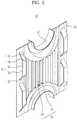
- FIG. 1is a perspective view illustrating a heat exchanger according to an embodiment of the present disclosure.
- a heat exchanger 10includes a refrigerant pipe 20, in which a refrigerant flows, and heat exchanger fins 30 coupled to the outer circumference of the refrigerant pipe 20.
- the refrigerant pipe 20is configured in the shape of a hollow tube in which the refrigerant flows.
- the refrigerant pipe 20is lengthened to increase heat exchange area between the refrigerant flowing in the refrigerant pipe 20 and external air.
- the refrigerant flowing in the refrigerant pipe 20is formed by mixing different Freon products exhibiting different properties.
- R-134a and R410Amay be used.
- the refrigerantmay be phase changed (compressed) from a gas state to a liquid state to perform heat exchange with external air.
- the refrigerantmay be phase changed (expanded) from a liquid state to a gas state to perform heat exchange with external air.
- the heat exchanger 10is used as a condenser.
- the heat exchanger 10is used as an evaporator.
- the refrigerant, flowing in the refrigerant pipe 20,is compressed or expanded to discharge heat to the surroundings or to absorb heat from the surroundings.
- the heat exchanger fins 30are coupled to the refrigerant pipe 20 so that the refrigerant efficiently discharges or absorbs heat during compression or expansion.
- the heat exchanger fins 30are disposed at a predetermined interval in the direction in which the refrigerant pipe 20 extends.
- the heat exchanger fins 30may be made of various metal materials, such as aluminum, exhibiting high thermal conductivity.
- the heat exchanger fins 30are coupled to the outer circumference of the refrigerant pipe 20 in a contact state to increase contact area between the refrigerant pipe 20 and external air.
- the interval between the heat exchanger fins 30may be reduced to increase the number of the heat exchanger fins 30. If the interval between the heat exchanger fins 30 is too small, however, the heat exchanger fins 30 may act as resistance to air F introduced to the heat exchanger 10, as shown in FIG. 1 , resulting in pressure loss. For this reason, the interval between the heat exchanger fins 30 may be properly adjusted.
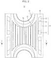
- FIG. 2is a perspective view illustrating part of one of the heat exchanger fins of FIG. 1
- FIG. 3is a front view of FIG. 2
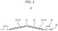
- FIG. 4is a sectional view taken along line I-I of FIG. 3
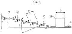
- FIG. 5is an enlarged sectional view illustrating part of FIG. 4 .
- the heat exchanger fin 30includes a plate 40, a protrusion 70 protruding from the plate 40, slits 50 provided at opposite sides of the protrusion 70, and a louver unit 60 provided at the protrusion 70.
- the plate 40is made of an aluminum alloy.
- the plate 40is thin.
- the plate 40includes location holes 32, through which the refrigerant pipe 20 extends in a contact state.
- Each of the location holes 32contacts the outer circumference of the refrigerant pipe 20 to support the refrigerant pipe 20.
- Each of the location holes 32is formed in a shape corresponding to the outer circumference of the refrigerant pipe 20 to surround the refrigerant pipe 20.
- each of the location holes 32protrudes frontward and rearward from the plate 40 to stably support the refrigerant pipe 20 and to increase contact area between the refrigerant pipe 20 and the heat exchanger fin 30 so that heat exchange is smoothly achieved.
- the protrusion 70protrudes frontward from the plate 40.
- the protrusion 70includes first inclined surfaces 72 disposed at a predetermined angle relative to the plate 40.
- the first inclined surfaces 72are disposed on the plate 40 in a symmetrical fashion to form a 'V' shape.
- the first inclined surfaces 72guide air, passing through the slits 50, to the louver unit 60. That is, air, accelerated while passing through the slits 50, naturally flows along the first inclined surfaces 72 so that speed of the air is not reduced.
- the air flowing along the first inclined surfaces 72contacts the louver unit 60 to perform heat exchange with the refrigerant flowing in the refrigerant pipe 20, thereby increasing heat transfer efficiency.
- the first inclined surfaces 72are disposed on the plate 40 in a symmetrical fashion to form a 'V' shape.
- a contact line 74is formed vertically at a position where the first inclined surfaces 72 join each other. The distance between the contact line 74 and the plate 40 constitutes a height H of the protrusion 70.
- the height H of the protrusion 70is increased, the area of the first inclined surfaces 72 increases, thereby increasing the contact area between the first inclined surfaces 72 and external air. If the height H of the protrusion 70 is excessively increased, however, the first inclined surfaces 72 act as resistance to external air. As a result, the speed of air is reduced and pressure of the air is reduced (pressure loss), thereby reducing heat transfer efficiency.
- the height H of the protrusion 70is 0.5 mm to 4.0 mm.
- first inclined surfaces 72may be disposed on the plate in a non-symmetrical fashion, which will be described in detail below in connection with a heat exchanger fin 300 according to another embodiment of the present disclosure.
- the slits 50are disposed at opposite sides of the protrusion 70.
- the slits 50prevent moisture contained in external air from being attached to the surface of the heat exchanger fin 30. Also, the slits accelerate external air introduced to the heat exchanger 10 and guide the external air to the protrusion 70 and the louver unit 60.
- Each of the slits 50includes second inclined surfaces 52 inclined relative to the plate 40, a top surface 54 provided between the second inclined surfaces 52, and a second cutout 56 provided at the rear of the top surface 54.
- the second inclined surfaces 52protrude from the plate 40 so that the second inclined surfaces 52 are disposed at a predetermined angle relative to the plate 40 to define a space, in which external air flows, between the plate 40 and the top surface 54.
- the top surface 54is formed in an approximately trapezoidal shape.
- the top surface 54is disposed between the second inclined surfaces 52. Air, passing through each of the slits 50, is divided by the top surface 54 and flows along the front and rear of the top surface 54, resulting in turbulent flow. As a result, the air is further accelerated.
- the top surface 54may be formed in other shapes.
- the top surface 54may be formed in the shape of a triangle, a semicircle, an arc or a quadrangle. Even if the top surface 54 is formed in any one of the above-specified shapes, the same effect in that air, passing through each of the slits 50, is divided by the top surface 54 is achieved.
- An edge 58is formed between top surface 54 and each of the second inclined surfaces 52.
- the edge 58prevents frost formation.
- Frost formationis a phenomenon in which moisture contained in external air is attached to the surface of the heat exchanger fin 30 in a frozen state.
- Frostis formed at a flat surface on which more than a predetermined amount of moisture is easily collected. More than a predetermined amount of moisture is prevented from being collected by the provision of the edge 58, thereby preventing or retarding frost formation.
- the second cutout 56is provided at the rear of the top surface 54 to guide external air, introduced to the heat exchanger 10, to the louver unit 60 and to minimize resistance applied to the air flowing along the top surface 54.
- the heat exchanger 10When the heat exchanger 10 is used as an evaporator to heat a room, the refrigerant, flowing in the refrigerant pipe 20, is expanded from a liquid state to a gas state to absorb heat from the surroundings. As a result, the surface temperature of the refrigerant pipe 20 is generally lowered to below zero degrees Celsius.
- the second cutout 56retards heat exchange between the refrigerant pipe 20 and the corresponding slit 50, thereby preventing frost formation.
- the width D of the top surface 54may be 0.5 to 5.0 mm in consideration of resistance applied to air passing through the corresponding slit 50.
- the slits 50are disposed at opposite sides of the protrusion 70. At least two slits 50 may be disposed in the vertical direction of the plate 40 so that the slits 50 are spaced apart from each other.
- the strength of the slits 50 and the plate 40is higher than when the slits are disposed without separation.
- the louver unit 60is provided at the protrusion 70.
- the louver unit 60includes guide plates 62 provided at the first inclined surfaces 72 and first cutout 64 alternating with the guide plates 62.
- the guide plates 62are disposed at a predetermined angle relative to the first inclined surfaces 72.
- the guide plates 62are arranged in parallel to each other so that the guide plates 62 are spaced apart from each other.
- External airaccelerated after having passed through the slits 50, flows along the first inclined surfaces 72 and contacts the guide plates 62 to perform heat exchange with the guide plates 62.
- the guide plates 62increase contact area between the heat exchanger fin 30 and external air to increase heat exchange efficiency.
- the pitch (width) P of each of the guide plates 62is small or when the inclination angle ⁇ between each of the guide plates 62 and the first inclined angle 72 is small, contact area between the heat exchanger fin 30 and external air increases. If the pitch P is too small or the inclination angle ⁇ is too large, however, speed of air passing through the louver unit 60 is reduced by the guide plates 62, resulting in pressure loss. As a result, overall heat exchange efficiency is lowered. Consequently, the pitch P and the inclination angle ⁇ are properly adjusted.
- the pitch Pmay be 0.5 mm to 3.0 mm and the inclination angle ⁇ may be 10 degrees to 60 degrees.
- each of the guide plates 62prevents or retards frost formation, as previously described.
- the first cutouts 64are provided at the first inclined surfaces 72 so that the first cutouts 64 and the guide plates 62 are alternately disposed.
- the first cutouts 64guide external air, accelerated after having passed through the slits 50, to flow along one side of each of the guide plates 62, thereby effectively achieving heat transfer between the guide plates 62 and external air.
- FIG. 6is a view illustrating air flow around the heat exchanger fin of FIG. 3
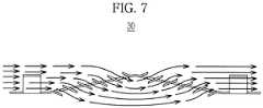
- FIG. 7is a sectional view taken along line II-II of FIG. 6 .
- FIGS. 6 and 7illustrate calculation results of air flow around the heat exchanger fin 30 using computational fluid dynamics (CFD).
- CFDcomputational fluid dynamics
- the slits 50accelerate air introduced into the slits 50 and guide the introduced air to the louver unit 60.
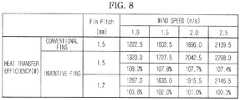
- FIG. 8is a table illustrating heat exchange efficiency of the heat exchanger fin of FIG. 3 .
- FIGS. 9 and 10are a front view and a sectional view illustrating a conventional fin compared with the heat exchange efficiency of the heat exchanger fin of FIG. 3 .
- a conventional fin 1is provided at the middle thereof with silts 5 but does not include a protrusion 70 and a louver unit 60, which are included in the heat exchanger fin 30 of FIG. 3 .
- wind speedindicates speed of external air introduced to the fin
- fin pitchindicates the distance between the respective fins. Smaller pitch means that a larger number of fins may be disposed in a limited space.
- the inventive finshave approximately 7.4 % to 8.2 % higher heat transfer efficiency in all wind speed sections than the conventional fins.
- the inventive finshave higher heat transfer efficiency than the conventional fins having a pitch of 1.5 mm. This means that higher heat transfer efficiency is achieved using a smaller number of inventive fins, thereby reducing material costs.
- FIGS. 11 to 19are front views and sectional views illustrating heat exchanger fins 200, 300, 400, 500 and 600 according to other embodiments of the present disclosure.
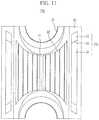
- FIG. 11illustrates a heat exchanger fin 200 according to another embodiment of the present disclosure.
- a slit 250, protruding frontward from the heat exchanger fin 200,is formed as a single body.
- FIGS. 12 and 13illustrate a heat exchanger fin 300 according to another embodiment of the present disclosure.
- a protrusion 370 of the heat exchanger fin 300is formed in a non-symmetrical shape. That is, first inclined surfaces 372a and 372b constituting the protrusion 370 are formed in a non-symmetrical 'V' shape.
- An inclination angle ⁇ between the first inclined surface 372a and the front of a plate 40is larger than an inclination angle ⁇ ' between the first inclined surface 372b and the front of the plate 40. Consequently, the area of the first inclined surface 372a is smaller than that of the first inclined surface 372b. Also, a contact line 374 at which the first inclined surfaces 372a and 372b join each other deviates from the middle of the plate 40.
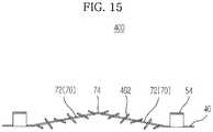
- FIGS. 14 and 15illustrate a heat exchanger fin 400 according to another embodiment of the present disclosure.
- Guide plates 462 provided at a louver unit 60 of the heat exchanger fin 400have different inclination angles.
- the guide plates 462may be provided at first inclined surfaces 72 so that the guide plates 462 are at different inclination angles relative to the first inclined surfaces 72.
- FIGS. 16 and 17illustrate a heat exchanger fin 500 which does not form part of the present invention. Slits 50, protruding frontward from the heat exchanger fin 500, are provided at only one side of a protrusion 700.
- the slits 50are disposed at an external air introduction side.
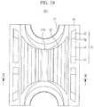
- FIGS. 18 and 19illustrate a heat exchanger fin 600 according to yet another embodiment of the present disclosure.
- a protrusion 670 of the heat exchanger fin 600includes a flat surface 676.
- the flat surface 676is provided between first inclined surfaces 672.
- the first inclined surfaces 672may be symmetric with respect to the flat surface 676.
- the distance between the flat surface 676 and a plate 40constitutes the height of the protrusion 670.
- the height of the protrusion 670is 0.5 mm to 4.0 mm.
- Guide plates 62may be selectively provided at the first inclined surfaces 672 or the flat surface 676. Alternatively, the guide plates 62 may be provided at both the first inclined surfaces 672 and the flat surface 676.
- the guide plates 462may be provided at the first inclined surfaces 372a and 372b of the protrusion 370 formed in a non-symmetrical shape (characteristic of the embodiment of FIG. FIGS. 12 and 13 ) so that the guide plates 462 are at different inclination angles to the first inclined surfaces 372a and 372b (characteristic of the embodiment of FIGS. 14 and 15 ).
- frost formationis restrained on the surfaces of the heat exchanger fins, thereby improving heat exchange efficiency.
Landscapes
- Engineering & Computer Science (AREA)
- Physics & Mathematics (AREA)
- Mechanical Engineering (AREA)
- General Engineering & Computer Science (AREA)
- Thermal Sciences (AREA)
- Geometry (AREA)
- Chemical & Material Sciences (AREA)
- Combustion & Propulsion (AREA)
- Heat-Exchange Devices With Radiators And Conduit Assemblies (AREA)
Description
- Embodiments of the present disclosure relate to a heat exchanger with an improved heat exchange structure.
- A heat exchanger is mounted in devices operating based upon a refrigeration cycle, such as air conditioners or refrigerators. The heat exchanger includes a plurality of heat exchanger fins and a refrigerant pipe extending through the heat exchanger fins to guide a refrigerant. Contact area between the heat exchanger fins and external air introduced to the heat exchanger is increased to improve heat exchange efficiency between the refrigerant flowing in the refrigerant pipe and the external air.
- When the contact area between the heat exchanger fins and external air contacting the heat exchanger fins is large or when resistance applied to air contacting the heat exchanger fins is small, heat exchange efficiency is increased. However, if the contact area between the heat exchanger fins and air is too large, large resistance is applied to air passing through the heat exchanger fins. On the other hand, if the contact area is reduced to lower resistance applied to air, heat exchange efficiency is lowered. For this reason, it may be necessary to provide fins having an optimal shape based on the heat exchanger employed.
- For a heat exchanger used as an evaporator (that is, the refrigeration cycle performs a heating operation), if outdoor temperature is too low, the surface temperature of the heat exchanger is lowered to below zero Celsius, and moisture contained in outdoor air is attached to the surface of the cold heat exchanger in a frozen state, thereby reducing heat exchange efficiency of the heat exchanger.
US 4,705,105 A discloses a heat exchanger with the features of the pre-characterizing part ofclaim 1. It discloses a room air conditioner with a nest of tubes and numerous thin metallic fins attached thereto. Further used are an evaporator and a condenser wherein it is said that thermally conducting tubes of the evaporator and condenser are air cooled by a corresponding flow of air passing the tubes and associated fins. Such a fin may comprise a plate and a protrusion protruding from the plate. Each protrusion is provided with a louver unit to perform heat exchange with the air passing therethrough.US 4,676,304 A discloses a heat exchanger with a flat metal tube and a plurality of corrugated fin units disposed therebetween. There seems to be no coupling of corresponding heat exchanger fins or fin units to an outer circumference of the refrigerant pipe. Fin units comprise a plurality of plate portions, each comprising inclined louvers and parallel lovers.US 2002/003035 A1 discloses slits provided on both surfaces of corresponding air guide fins. However, there is no protrusion and there are no slits disposed on opposite sides of the protrusion, namely the left and right sides of such protrusion.US 2001/004012 A1 discloses a fin and tube type heat-exchanger with a number of slit groups in each of which slits are arranged in a number of rows and are formed on each stage, namely upper stage and lower stage of each cooling fin.US 2005/077036 A1 discloses fins for heat exchanger only with a plurality of louvers without any slits and without any protrusion.- It is an object of the present disclosure to provide a heat exchanger having a structure to effectively achieve heat exchange between air and heat exchanger fins and to restrain frost formation on the surfaces of heat exchanger fins.
- Additional aspects of the disclosure will be set forth in part in the description which follows and, in part, will be apparent from the description, or may be learned by practice of the disclosure.
- The object is solved by the features according to the independent claim.
- Advantageous embodiments are disclosed by the subclaims.
- The louver unit may include first cutouts provided at the protrusion and a plurality of guide plates provided in parallel to each other so that the guide plates are spaced apart from each other by the respective first cutouts, the first cutouts and the guide plates being alternately arranged.
- Each of the guide plates may have a width of 0.5 mm to 3 mm.
- The protrusion may include first inclined surfaces inclined relative to the plate, the guide plates may be provided at the first inclined surfaces, and the angle between the guide plates and the first inclined surfaces may be 10 to 60 degrees.
- Each of the slits includes second inclined surfaces inclined relative to the plate, a top surface formed between the second inclined surfaces, and a second cutout provided at the rear of the top surface.
- The top surface may have a width of 0.5 mm to 5 mm.
- The first inclined surfaces may be disposed at the plate in a symmetrical fashion, the distance between a line formed at the position where the first inclined surfaces join each other and the plate may constitute a height of the protrusion, and the protrusion may have a height of 0.5 mm to 4 mm.
- The first inclined surfaces may be disposed at the plate in a symmetrical fashion, the distance between a flat surface connected between the first inclined surfaces and the plate may constitute a height of the protrusion, and the protrusion may have a height of 0.5 mm to 4 mm.
- The heat exchanger fin may include a plurality of plates stacked at an interval.
- The protrusion may include first inclined surfaces disposed in a symmetrical fashion to form a 'V' shape, and the guide plates and the first cutouts may be provided at the first inclined surfaces.
- The angle between the first inclined surfaces and the guide plates provided at the first inclined surfaces may be 10 to 60 degrees.
- The protrusion may include first inclined surfaces disposed in a symmetrical fashion and a flat surface connected between the first inclined surfaces, the guide plates and the first cutouts being provided at the first inclined surfaces or the flat surface.
- These and/or other aspects of the disclosure will become apparent and more readily appreciated from the following description of the embodiments, taken in conjunction with the accompanying drawings of which:
FIG. 1 is a perspective view illustrating a heat exchanger according to an embodiment of the present disclosure;FIG. 2 is a perspective view illustrating part of a heat exchanger fin ofFIG. 1 ;FIG. 3 is a front view ofFIG. 2 ;FIG. 4 is a sectional view taken along line I-I ofFIG. 3 ;FIG. 5 is an enlarged sectional view illustrating part ofFIG. 4 ;FIG. 6 is a view illustrating air flow around the heat exchanger fin ofFIG. 3 ;FIG. 7 is a sectional view taken along line II-II ofFIG. 6 ;FIG. 8 is a table illustrating heat exchange efficiency of the heat exchanger fin ofFIG. 3 ;FIG. 9 is a front view illustrating a conventional fin;FIG. 10 is a sectional view taken along line A-A ofFIG. 9 ;FIG. 11 is a front view illustrating a heat exchanger according to another embodiment of the present disclosure;FIG. 12 is a front view illustrating a heat exchanger according to another embodiment of the present disclosure;FIG. 13 is a sectional view taken along line III-III ofFIG. 12 ;FIG. 14 is a front view illustrating a heat exchanger according to another embodiment of the present disclosure;FIG. 15 is a sectional view taken along line IV-IV ofFIG. 14 ;FIG. 16 is a front view illustrating a heat exchanger not forming part of the present invention,FIG. 17 is a sectional view taken along line V-V ofFIG. 16 ;FIG. 18 is a front view illustrating a heat exchanger according to yet another embodiment of the present disclosure; andFIG. 19 is a sectional view taken along line VI-VI ofFIG. 18 .- Reference will now be made in detail to the embodiments of the present disclosure, examples of which are illustrated in the accompanying drawings, wherein like reference numerals refer to like elements throughout.
FIG. 1 is a perspective view illustrating a heat exchanger according to an embodiment of the present disclosure.- As shown in
FIG. 1 , aheat exchanger 10 includes arefrigerant pipe 20, in which a refrigerant flows, andheat exchanger fins 30 coupled to the outer circumference of therefrigerant pipe 20. - The
refrigerant pipe 20 is configured in the shape of a hollow tube in which the refrigerant flows. Therefrigerant pipe 20 is lengthened to increase heat exchange area between the refrigerant flowing in therefrigerant pipe 20 and external air. However, it may be difficult to extend therefrigerant pipe 20 in one direction due to spatial restrictions. Consequently, therefrigerant pipe 20 is repeatedly bent at opposite ends of theheat exchanger 10 in opposite directions to efficiently increase heat exchange area per unit volume. - The refrigerant flowing in the
refrigerant pipe 20 is formed by mixing different Freon products exhibiting different properties. For example, R-134a and R410A may be used. - The refrigerant may be phase changed (compressed) from a gas state to a liquid state to perform heat exchange with external air. On the other hand, the refrigerant may be phase changed (expanded) from a liquid state to a gas state to perform heat exchange with external air. When the refrigerant is phase changed from a gas state to a liquid state, the
heat exchanger 10 is used as a condenser. When the refrigerant is phase changed from a liquid state to a gas state, theheat exchanger 10 is used as an evaporator. - The refrigerant, flowing in the
refrigerant pipe 20, is compressed or expanded to discharge heat to the surroundings or to absorb heat from the surroundings. Theheat exchanger fins 30 are coupled to therefrigerant pipe 20 so that the refrigerant efficiently discharges or absorbs heat during compression or expansion. - The
heat exchanger fins 30 are disposed at a predetermined interval in the direction in which therefrigerant pipe 20 extends. - The
heat exchanger fins 30 may be made of various metal materials, such as aluminum, exhibiting high thermal conductivity. Theheat exchanger fins 30 are coupled to the outer circumference of therefrigerant pipe 20 in a contact state to increase contact area between therefrigerant pipe 20 and external air. - The interval between the
heat exchanger fins 30 may be reduced to increase the number of theheat exchanger fins 30. If the interval between theheat exchanger fins 30 is too small, however, theheat exchanger fins 30 may act as resistance to air F introduced to theheat exchanger 10, as shown inFIG. 1 , resulting in pressure loss. For this reason, the interval between theheat exchanger fins 30 may be properly adjusted. FIG. 2 is a perspective view illustrating part of one of the heat exchanger fins ofFIG. 1 ,FIG. 3 is a front view ofFIG. 2 ,FIG. 4 is a sectional view taken along line I-I ofFIG. 3 , andFIG. 5 is an enlarged sectional view illustrating part ofFIG. 4 .- As shown in
FIGS. 2 to 5 , theheat exchanger fin 30 includes aplate 40, aprotrusion 70 protruding from theplate 40, slits 50 provided at opposite sides of theprotrusion 70, and alouver unit 60 provided at theprotrusion 70. - The
plate 40 is made of an aluminum alloy. Theplate 40 is thin. Theplate 40 includes location holes 32, through which therefrigerant pipe 20 extends in a contact state. - Each of the location holes 32 contacts the outer circumference of the
refrigerant pipe 20 to support therefrigerant pipe 20. Each of the location holes 32 is formed in a shape corresponding to the outer circumference of therefrigerant pipe 20 to surround therefrigerant pipe 20. - As shown in
FIG. 2 , each of the location holes 32 protrudes frontward and rearward from theplate 40 to stably support therefrigerant pipe 20 and to increase contact area between therefrigerant pipe 20 and theheat exchanger fin 30 so that heat exchange is smoothly achieved. - The
protrusion 70 protrudes frontward from theplate 40. - The
protrusion 70 includes firstinclined surfaces 72 disposed at a predetermined angle relative to theplate 40. The firstinclined surfaces 72 are disposed on theplate 40 in a symmetrical fashion to form a 'V' shape. - The first
inclined surfaces 72 guide air, passing through theslits 50, to thelouver unit 60. That is, air, accelerated while passing through theslits 50, naturally flows along the firstinclined surfaces 72 so that speed of the air is not reduced. The air flowing along the firstinclined surfaces 72 contacts thelouver unit 60 to perform heat exchange with the refrigerant flowing in therefrigerant pipe 20, thereby increasing heat transfer efficiency. - As previously described, the first
inclined surfaces 72 are disposed on theplate 40 in a symmetrical fashion to form a 'V' shape. Acontact line 74 is formed vertically at a position where the firstinclined surfaces 72 join each other. The distance between thecontact line 74 and theplate 40 constitutes a height H of theprotrusion 70. - If the height H of the
protrusion 70 is increased, the area of the firstinclined surfaces 72 increases, thereby increasing the contact area between the firstinclined surfaces 72 and external air. If the height H of theprotrusion 70 is excessively increased, however, the firstinclined surfaces 72 act as resistance to external air. As a result, the speed of air is reduced and pressure of the air is reduced (pressure loss), thereby reducing heat transfer efficiency. The height H of theprotrusion 70 is 0.5 mm to 4.0 mm. - Meanwhile, the first
inclined surfaces 72 may be disposed on the plate in a non-symmetrical fashion, which will be described in detail below in connection with aheat exchanger fin 300 according to another embodiment of the present disclosure. - The
slits 50 are disposed at opposite sides of theprotrusion 70. - The
slits 50 prevent moisture contained in external air from being attached to the surface of theheat exchanger fin 30. Also, the slits accelerate external air introduced to theheat exchanger 10 and guide the external air to theprotrusion 70 and thelouver unit 60. Each of theslits 50 includes secondinclined surfaces 52 inclined relative to theplate 40, atop surface 54 provided between the secondinclined surfaces 52, and asecond cutout 56 provided at the rear of thetop surface 54. - The second
inclined surfaces 52 protrude from theplate 40 so that the secondinclined surfaces 52 are disposed at a predetermined angle relative to theplate 40 to define a space, in which external air flows, between theplate 40 and thetop surface 54. - The
top surface 54 is formed in an approximately trapezoidal shape. Thetop surface 54 is disposed between the second inclined surfaces 52. Air, passing through each of theslits 50, is divided by thetop surface 54 and flows along the front and rear of thetop surface 54, resulting in turbulent flow. As a result, the air is further accelerated. - The
top surface 54 may be formed in other shapes. For example, thetop surface 54 may be formed in the shape of a triangle, a semicircle, an arc or a quadrangle. Even if thetop surface 54 is formed in any one of the above-specified shapes, the same effect in that air, passing through each of theslits 50, is divided by thetop surface 54 is achieved. - An
edge 58 is formed betweentop surface 54 and each of the second inclined surfaces 52. Theedge 58 prevents frost formation. Frost formation is a phenomenon in which moisture contained in external air is attached to the surface of theheat exchanger fin 30 in a frozen state. Frost is formed at a flat surface on which more than a predetermined amount of moisture is easily collected. More than a predetermined amount of moisture is prevented from being collected by the provision of theedge 58, thereby preventing or retarding frost formation. - The
second cutout 56 is provided at the rear of thetop surface 54 to guide external air, introduced to theheat exchanger 10, to thelouver unit 60 and to minimize resistance applied to the air flowing along thetop surface 54. - When the
heat exchanger 10 is used as an evaporator to heat a room, the refrigerant, flowing in therefrigerant pipe 20, is expanded from a liquid state to a gas state to absorb heat from the surroundings. As a result, the surface temperature of therefrigerant pipe 20 is generally lowered to below zero degrees Celsius. Thesecond cutout 56 retards heat exchange between therefrigerant pipe 20 and thecorresponding slit 50, thereby preventing frost formation. - The width D of the
top surface 54 may be 0.5 to 5.0 mm in consideration of resistance applied to air passing through thecorresponding slit 50. - The
slits 50 are disposed at opposite sides of theprotrusion 70. At least twoslits 50 may be disposed in the vertical direction of theplate 40 so that theslits 50 are spaced apart from each other. - When the slits are disposed in the vertical direction of the
plate 40 so that theslits 50 are spaced apart from each other, the strength of theslits 50 and theplate 40 is higher than when the slits are disposed without separation. - The
louver unit 60 is provided at theprotrusion 70. - The
louver unit 60 includesguide plates 62 provided at the firstinclined surfaces 72 andfirst cutout 64 alternating with theguide plates 62. - The
guide plates 62 are disposed at a predetermined angle relative to the first inclined surfaces 72. Theguide plates 62 are arranged in parallel to each other so that theguide plates 62 are spaced apart from each other. - External air, accelerated after having passed through the
slits 50, flows along the firstinclined surfaces 72 and contacts theguide plates 62 to perform heat exchange with theguide plates 62. Theguide plates 62 increase contact area between theheat exchanger fin 30 and external air to increase heat exchange efficiency. - When the pitch (width) P of each of the
guide plates 62 is small or when the inclination angle α between each of theguide plates 62 and the firstinclined angle 72 is small, contact area between theheat exchanger fin 30 and external air increases. If the pitch P is too small or the inclination angle α is too large, however, speed of air passing through thelouver unit 60 is reduced by theguide plates 62, resulting in pressure loss. As a result, overall heat exchange efficiency is lowered. Consequently, the pitch P and the inclination angle α are properly adjusted. For example, the pitch P may be 0.5 mm to 3.0 mm and the inclination angle α may be 10 degrees to 60 degrees. - Also, the edge of each of the
guide plates 62 prevents or retards frost formation, as previously described. - The
first cutouts 64 are provided at the firstinclined surfaces 72 so that thefirst cutouts 64 and theguide plates 62 are alternately disposed. Thefirst cutouts 64 guide external air, accelerated after having passed through theslits 50, to flow along one side of each of theguide plates 62, thereby effectively achieving heat transfer between theguide plates 62 and external air. FIG. 6 is a view illustrating air flow around the heat exchanger fin ofFIG. 3 , andFIG. 7 is a sectional view taken along line II-II ofFIG. 6 .FIGS. 6 and7 illustrate calculation results of air flow around theheat exchanger fin 30 using computational fluid dynamics (CFD). In the drawings, lines indicate air flow direction, and lengths of the lines indicate air speed. Longer lengths of the lines represent higher air speed.- As shown in
FIGS. 6 and7 , air passing through theslits 50 of theheat exchanger fin 30 moves faster than air not passing through theslits 50 since the air introduced into theslits 50 is accelerated by thetop surface 54 of each of theslits 50. - The air, accelerated by the
slits 50, flows to thelouver unit 60 without reduction of air speed. As previously described, theslits 50 accelerate air introduced into theslits 50 and guide the introduced air to thelouver unit 60. - The air flows on the surfaces of the
guide plates 62 and between theguide plates 62, i.e. at thefirst cutouts 64, at high speed to perform heat exchange with theguide plates 62. FIG. 8 is a table illustrating heat exchange efficiency of the heat exchanger fin ofFIG. 3 .FIGS. 9 and10 are a front view and a sectional view illustrating a conventional fin compared with the heat exchange efficiency of the heat exchanger fin ofFIG. 3 .- As shown in
FIGS. 9 and10 , aconventional fin 1 is provided at the middle thereof withsilts 5 but does not include aprotrusion 70 and alouver unit 60, which are included in theheat exchanger fin 30 ofFIG. 3 . - In the table of
FIG. 8 , wind speed indicates speed of external air introduced to the fin, and fin pitch indicates the distance between the respective fins. Smaller pitch means that a larger number of fins may be disposed in a limited space. - As the result of a comparison of heat transfer efficiency between the conventional fins and the inventive fins having the same pitch (1.5 mm), the inventive fins have approximately 7.4 % to 8.2 % higher heat transfer efficiency in all wind speed sections than the conventional fins.
- Also, even when the pitch of the inventive fins is increased from 1.5 mm to 1.7 mm, the inventive fins have higher heat transfer efficiency than the conventional fins having a pitch of 1.5 mm. This means that higher heat transfer efficiency is achieved using a smaller number of inventive fins, thereby reducing material costs.
FIGS. 11 to 19 are front views and sectional views illustratingheat exchanger fins FIG. 11 illustrates aheat exchanger fin 200 according to another embodiment of the present disclosure. Aslit 250, protruding frontward from theheat exchanger fin 200, is formed as a single body.FIGS. 12 and13 illustrate aheat exchanger fin 300 according to another embodiment of the present disclosure. Aprotrusion 370 of theheat exchanger fin 300 is formed in a non-symmetrical shape. That is, firstinclined surfaces protrusion 370 are formed in a non-symmetrical 'V' shape.- An inclination angle β between the first
inclined surface 372a and the front of aplate 40 is larger than an inclination angle β' between the firstinclined surface 372b and the front of theplate 40. Consequently, the area of the firstinclined surface 372a is smaller than that of the firstinclined surface 372b. Also, acontact line 374 at which the firstinclined surfaces plate 40. FIGS. 14 and15 illustrate aheat exchanger fin 400 according to another embodiment of the present disclosure.Guide plates 462 provided at alouver unit 60 of theheat exchanger fin 400 have different inclination angles.- That is, the
guide plates 462 may be provided at firstinclined surfaces 72 so that theguide plates 462 are at different inclination angles relative to the first inclined surfaces 72. FIGS. 16 and17 illustrate aheat exchanger fin 500 which does not form part of the present invention.Slits 50, protruding frontward from theheat exchanger fin 500, are provided at only one side of a protrusion 700.- In this case, the
slits 50 are disposed at an external air introduction side. FIGS. 18 and19 illustrate aheat exchanger fin 600 according to yet another embodiment of the present disclosure. Aprotrusion 670 of theheat exchanger fin 600 includes aflat surface 676.- The
flat surface 676 is provided between firstinclined surfaces 672. The firstinclined surfaces 672 may be symmetric with respect to theflat surface 676. The distance between theflat surface 676 and aplate 40 constitutes the height of theprotrusion 670. The height of theprotrusion 670 is 0.5 mm to 4.0 mm. Guide plates 62 may be selectively provided at the firstinclined surfaces 672 or theflat surface 676. Alternatively, theguide plates 62 may be provided at both the firstinclined surfaces 672 and theflat surface 676.- At least two of the previous embodiments may be combined. For example, when the embodiment of
FIGS. 12 and13 and the embodiment ofFIGS. 14 and15 are combined, theguide plates 462 may be provided at the firstinclined surfaces protrusion 370 formed in a non-symmetrical shape (characteristic of the embodiment of FIG.FIGS. 12 and13 ) so that theguide plates 462 are at different inclination angles to the firstinclined surfaces FIGS. 14 and15 ). - As is apparent from the above description, heat exchange between air and the heat exchanger fins of the embodiments of the present disclosure is effectively achieved, thereby improving heat exchange efficiency.
- Also, frost formation is restrained on the surfaces of the heat exchanger fins, thereby improving heat exchange efficiency.
- Although a few embodiments of the present disclosure have been shown and described, it would be appreciated by those skilled in the art that changes may be made in these embodiments without departing from the principles of the invention, the scope of which is defined in the claims.
Claims (9)
- A heat exchanger (10) comprising:a refrigerant pipe (20) in which a refrigerant flows; anda heat exchanger fin (30, 200, 300, 400, 600) coupled to an outer circumference of the refrigerant pipe (20), wherein the heat exchanger fin comprises:characterized bya plate (40);a protrusion (70, 370, 670) protruding from the plate (40);a louver unit (60) provided at the protrusion to perform heat exchange;
slits (50) disposed at right and left sides of the protrusion (70, 370, 670) to guide air to the protrusion, wherein said louver unit (60) is adapted to perform said heat exchange with the air having passed through the slits (50), and
wherein air flows in the slits disposed at the right side of the protrusion, and then passes through the protrusion, and finally flows out of the slits disposed at the left side of the protrusion. - The heat exchanger according to claim 1, wherein the louver unit (60) comprises:first cutouts (64) provided at the protrusion (70); anda plurality of guide plates (62, 462) provided in parallel to each other so that the guide plates are spaced apart from each other by the respective first cutouts (64),the first cutouts (64) and the guide plates (62, 462) being alternately arranged.
- The heat exchanger according to claim 2, wherein each of the guide plates (62) has a width of 0.5 mm to 3 mm.
- The heat exchanger according to claim 2, wherein
the protrusion (70, 470) comprises first inclined surfaces (72, 672, 372 a, b) inclined relative to the plate (40),
the guide plates (62, 462) are provided at the first inclined surfaces, and
an angle between the guide plates and the first inclined surfaces is 10 to 60 degrees. - The heat exchanger according to claim 1, wherein each of the slits (50) comprises:second inclined surfaces(52) inclined relative to the plate (40);a top surface (54) formed between the second inclined surfaces (52); anda second cutout (56) provided at a rear of the top surface (54).
- The heat exchanger according to claim 5, wherein the top surface (54) has a width of 0.5 mm to 5 mm.
- The heat exchanger according to claim 4, wherein
the first inclined surfaces (52) are disposed at the plate (40) in a symmetrical fashion, a distance between a line formed at a position where the first inclined surfaces join each other and the plate constitutes a height (H) of the protrusion (70, 470), and
the protrusion has a height of 0.5 mm to 4 mm. - The heat exchanger according to claim 4, wherein
the first inclined surfaces (52) are disposed at the plate (40) in a symmetrical fashion, a distance between a flat surface (676) connected between the first inclined surfaces (52) and the plate (40) constitutes a height (H) of the protrusion, and
the protrusion has a height of 0.5 mm to 4 mm. - The heat exchanger according to claim 1, wherein the heat exchanger fin (30, 200, 300, 400, 600) comprises a plurality of plates (40) stacked at an interval.
Applications Claiming Priority (1)
| Application Number | Priority Date | Filing Date | Title |
|---|---|---|---|
| KR1020100106371AKR20120044850A (en) | 2010-10-28 | 2010-10-28 | Heat exchanger |
Publications (3)
| Publication Number | Publication Date |
|---|---|
| EP2447656A2 EP2447656A2 (en) | 2012-05-02 |
| EP2447656A3 EP2447656A3 (en) | 2015-02-25 |
| EP2447656B1true EP2447656B1 (en) | 2016-12-21 |
Family
ID=44785705
Family Applications (1)
| Application Number | Title | Priority Date | Filing Date |
|---|---|---|---|
| EP11185348.7AActiveEP2447656B1 (en) | 2010-10-28 | 2011-10-17 | Heat Exchanger with louvered transversal fins |
Country Status (4)
| Country | Link |
|---|---|
| US (1) | US20120103587A1 (en) |
| EP (1) | EP2447656B1 (en) |
| KR (1) | KR20120044850A (en) |
| CN (1) | CN102455089B (en) |
Families Citing this family (10)
| Publication number | Priority date | Publication date | Assignee | Title |
|---|---|---|---|---|
| CN103851716A (en)* | 2012-11-28 | 2014-06-11 | 苏州昆拓热控系统股份有限公司 | High-effect cabinet air conditioner |
| FR3038977B1 (en)* | 2015-07-17 | 2019-08-30 | Valeo Systemes Thermiques | HEAT EXCHANGER WITH FINS COMPRISING IMPROVED PERSIANS |
| USD800282S1 (en)* | 2016-03-03 | 2017-10-17 | Lennox Industries Inc. | Heat exchanger fin |
| JP2018124047A (en)* | 2017-02-03 | 2018-08-09 | 三星電子株式会社Samsung Electronics Co.,Ltd. | Heat exchanger, method for manufacturing the same, and radiator |
| WO2018143619A1 (en) | 2017-02-03 | 2018-08-09 | Samsung Electronics Co., Ltd. | Heat exchanger and method of manufacturing the same |
| IL255877B (en)* | 2017-11-23 | 2019-12-31 | Dulberg Sharon | Device for extraction of water from air, and dehumidifying with high energy efficiency and methods for manufacturing thereof |
| US11236951B2 (en)* | 2018-12-06 | 2022-02-01 | Johnson Controls Technology Company | Heat exchanger fin surface enhancement |
| CN110726324A (en)* | 2019-11-19 | 2020-01-24 | 广东美的暖通设备有限公司 | Cooling fin for heat exchanger, cooling assembly and refrigeration equipment |
| CN111322683A (en)* | 2020-03-06 | 2020-06-23 | 青岛海信日立空调系统有限公司 | Air conditioner |
| EP4372303A4 (en)* | 2021-09-06 | 2024-11-13 | Mitsubishi Heavy Industries Thermal Systems, Ltd. | Fin for heat exchanger |
Family Cites Families (15)
| Publication number | Priority date | Publication date | Assignee | Title |
|---|---|---|---|---|
| US2789797A (en)* | 1953-08-20 | 1957-04-23 | Modine Mfg Co | Heat exchanger fin structure |
| US4328861A (en)* | 1979-06-21 | 1982-05-11 | Borg-Warner Corporation | Louvred fins for heat exchangers |
| JPS5656589A (en)* | 1979-10-15 | 1981-05-18 | Matsushita Electric Ind Co Ltd | Heat exchanger having fin |
| GB2169694B (en)* | 1985-01-15 | 1988-01-20 | Sanden Corp | Serpentine heat exchanger |
| JPS6256786A (en)* | 1985-09-06 | 1987-03-12 | Hitachi Ltd | Heat exchanger |
| US4705105A (en)* | 1986-05-06 | 1987-11-10 | Whirlpool Corporation | Locally inverted fin for an air conditioner |
| JPH02238297A (en)* | 1989-03-08 | 1990-09-20 | Nippondenso Co Ltd | Method of designing heat exchanger and evaluation method |
| US5501270A (en)* | 1995-03-09 | 1996-03-26 | Ford Motor Company | Plate fin heat exchanger |
| KR200144768Y1 (en)* | 1996-06-11 | 1999-06-15 | 윤종용 | Heat exchanger for refrigeration system |
| KR100477480B1 (en)* | 1997-12-30 | 2005-06-07 | 한라공조주식회사 | heat transmitter |
| FI109432B (en)* | 1999-03-16 | 2002-07-31 | Outokumpu Oy | Cooling element for heat exchanger |
| JP2001194084A (en)* | 1999-12-15 | 2001-07-17 | Lg Electronics Inc | Fin tube type heat exchanger |
| KR100347894B1 (en)* | 2000-07-06 | 2002-08-09 | 엘지전자주식회사 | Heat exchanger |
| US6805193B2 (en)* | 2002-01-24 | 2004-10-19 | Valeo, Inc. | Fin louver design for heat exchanger |
| US7428920B2 (en)* | 2003-08-21 | 2008-09-30 | Visteon Global Technologies, Inc. | Fin for heat exchanger |
- 2010
- 2010-10-28KRKR1020100106371Apatent/KR20120044850A/ennot_activeCeased
- 2011
- 2011-10-17EPEP11185348.7Apatent/EP2447656B1/enactiveActive
- 2011-10-24USUS13/317,602patent/US20120103587A1/ennot_activeAbandoned
- 2011-10-27CNCN201110342838.5Apatent/CN102455089B/enactiveActive
Also Published As
| Publication number | Publication date |
|---|---|
| KR20120044850A (en) | 2012-05-08 |
| EP2447656A2 (en) | 2012-05-02 |
| CN102455089A (en) | 2012-05-16 |
| CN102455089B (en) | 2015-11-25 |
| US20120103587A1 (en) | 2012-05-03 |
| EP2447656A3 (en) | 2015-02-25 |
Similar Documents
| Publication | Publication Date | Title |
|---|---|---|
| EP2447656B1 (en) | Heat Exchanger with louvered transversal fins | |
| EP2369285B1 (en) | Heat exchanger | |
| CN101963418B (en) | Micro channel heat exchanger for air-conditioner heat pump | |
| US20110030932A1 (en) | Multichannel heat exchanger fins | |
| WO2014091782A1 (en) | Flat tube heat exchange apparatus, and outdoor unit for air conditioner provided with same | |
| KR102174510B1 (en) | Refrigeration cycle of refrigerator | |
| CN104246413A (en) | Heat exchanger | |
| JPWO2012098912A1 (en) | Heat exchanger and air conditioner | |
| CN102200365B (en) | Refrigerator | |
| CN204063687U (en) | Heat exchanger and freezing cycle device | |
| EP3062037B1 (en) | Heat exchanger and refrigeration cycle device using said heat exchanger | |
| US20160298886A1 (en) | Heat exchanger and heat pump apparatus | |
| JPWO2017183180A1 (en) | Heat exchanger | |
| JPWO2019026239A1 (en) | Heat exchanger and refrigeration cycle apparatus | |
| US20120103582A1 (en) | Heat exchanger and micro-channel tube thereof | |
| WO2016085817A2 (en) | Frost tolerant microchannel heat exchanger | |
| WO2018040037A1 (en) | Micro-channel heat exchanger and air-cooled refrigerator | |
| JP7381909B2 (en) | Heat exchanger tubes and heat exchangers | |
| KR100493697B1 (en) | The refrigerator for improvement on heat exchange efficiency | |
| KR100941706B1 (en) | heat transmitter | |
| WO2018040034A1 (en) | Micro-channel heat exchanger and air-cooled refrigerator | |
| EP4300026B1 (en) | Heat exchange fin, heat exchanger, and heat pump system | |
| JP2017133815A (en) | Heat exchanger | |
| CN102538306A (en) | Heat exchanger structure | |
| JP6921323B2 (en) | Heat exchanger, heat exchanger unit, and refrigeration cycle equipment |
Legal Events
| Date | Code | Title | Description |
|---|---|---|---|
| PUAI | Public reference made under article 153(3) epc to a published international application that has entered the european phase | Free format text:ORIGINAL CODE: 0009012 | |
| AK | Designated contracting states | Kind code of ref document:A2 Designated state(s):AL AT BE BG CH CY CZ DE DK EE ES FI FR GB GR HR HU IE IS IT LI LT LU LV MC MK MT NL NO PL PT RO RS SE SI SK SM TR | |
| AX | Request for extension of the european patent | Extension state:BA ME | |
| RAP1 | Party data changed (applicant data changed or rights of an application transferred) | Owner name:SAMSUNG ELECTRONICS CO., LTD. | |
| PUAL | Search report despatched | Free format text:ORIGINAL CODE: 0009013 | |
| AK | Designated contracting states | Kind code of ref document:A3 Designated state(s):AL AT BE BG CH CY CZ DE DK EE ES FI FR GB GR HR HU IE IS IT LI LT LU LV MC MK MT NL NO PL PT RO RS SE SI SK SM TR | |
| AX | Request for extension of the european patent | Extension state:BA ME | |
| RIC1 | Information provided on ipc code assigned before grant | Ipc:F28F 1/32 20060101ALI20150122BHEP Ipc:F25B 39/02 20060101ALI20150122BHEP Ipc:F28D 1/047 20060101AFI20150122BHEP Ipc:F24F 1/18 20110101ALI20150122BHEP | |
| 17P | Request for examination filed | Effective date:20150825 | |
| RBV | Designated contracting states (corrected) | Designated state(s):AL AT BE BG CH CY CZ DE DK EE ES FI FR GB GR HR HU IE IS IT LI LT LU LV MC MK MT NL NO PL PT RO RS SE SI SK SM TR | |
| RIC1 | Information provided on ipc code assigned before grant | Ipc:F28F 1/32 20060101ALI20160517BHEP Ipc:F24F 1/18 20110101ALI20160517BHEP Ipc:F28D 1/047 20060101AFI20160517BHEP Ipc:F25B 39/02 20060101ALI20160517BHEP | |
| GRAP | Despatch of communication of intention to grant a patent | Free format text:ORIGINAL CODE: EPIDOSNIGR1 | |
| INTG | Intention to grant announced | Effective date:20160628 | |
| GRAS | Grant fee paid | Free format text:ORIGINAL CODE: EPIDOSNIGR3 | |
| GRAA | (expected) grant | Free format text:ORIGINAL CODE: 0009210 | |
| AK | Designated contracting states | Kind code of ref document:B1 Designated state(s):AL AT BE BG CH CY CZ DE DK EE ES FI FR GB GR HR HU IE IS IT LI LT LU LV MC MK MT NL NO PL PT RO RS SE SI SK SM TR | |
| REG | Reference to a national code | Ref country code:GB Ref legal event code:FG4D | |
| REG | Reference to a national code | Ref country code:CH Ref legal event code:EP | |
| REG | Reference to a national code | Ref country code:IE Ref legal event code:FG4D | |
| REG | Reference to a national code | Ref country code:AT Ref legal event code:REF Ref document number:855852 Country of ref document:AT Kind code of ref document:T Effective date:20170115 | |
| REG | Reference to a national code | Ref country code:DE Ref legal event code:R096 Ref document number:602011033568 Country of ref document:DE | |
| PG25 | Lapsed in a contracting state [announced via postgrant information from national office to epo] | Ref country code:LV Free format text:LAPSE BECAUSE OF FAILURE TO SUBMIT A TRANSLATION OF THE DESCRIPTION OR TO PAY THE FEE WITHIN THE PRESCRIBED TIME-LIMIT Effective date:20161221 | |
| REG | Reference to a national code | Ref country code:LT Ref legal event code:MG4D | |
| REG | Reference to a national code | Ref country code:NL Ref legal event code:MP Effective date:20161221 | |
| PG25 | Lapsed in a contracting state [announced via postgrant information from national office to epo] | Ref country code:LT Free format text:LAPSE BECAUSE OF FAILURE TO SUBMIT A TRANSLATION OF THE DESCRIPTION OR TO PAY THE FEE WITHIN THE PRESCRIBED TIME-LIMIT Effective date:20161221 Ref country code:NO Free format text:LAPSE BECAUSE OF FAILURE TO SUBMIT A TRANSLATION OF THE DESCRIPTION OR TO PAY THE FEE WITHIN THE PRESCRIBED TIME-LIMIT Effective date:20170321 Ref country code:GR Free format text:LAPSE BECAUSE OF FAILURE TO SUBMIT A TRANSLATION OF THE DESCRIPTION OR TO PAY THE FEE WITHIN THE PRESCRIBED TIME-LIMIT Effective date:20170322 Ref country code:SE Free format text:LAPSE BECAUSE OF FAILURE TO SUBMIT A TRANSLATION OF THE DESCRIPTION OR TO PAY THE FEE WITHIN THE PRESCRIBED TIME-LIMIT Effective date:20161221 | |
| REG | Reference to a national code | Ref country code:AT Ref legal event code:MK05 Ref document number:855852 Country of ref document:AT Kind code of ref document:T Effective date:20161221 | |
| PG25 | Lapsed in a contracting state [announced via postgrant information from national office to epo] | Ref country code:FI Free format text:LAPSE BECAUSE OF FAILURE TO SUBMIT A TRANSLATION OF THE DESCRIPTION OR TO PAY THE FEE WITHIN THE PRESCRIBED TIME-LIMIT Effective date:20161221 Ref country code:RS Free format text:LAPSE BECAUSE OF FAILURE TO SUBMIT A TRANSLATION OF THE DESCRIPTION OR TO PAY THE FEE WITHIN THE PRESCRIBED TIME-LIMIT Effective date:20161221 Ref country code:HR Free format text:LAPSE BECAUSE OF FAILURE TO SUBMIT A TRANSLATION OF THE DESCRIPTION OR TO PAY THE FEE WITHIN THE PRESCRIBED TIME-LIMIT Effective date:20161221 | |
| PG25 | Lapsed in a contracting state [announced via postgrant information from national office to epo] | Ref country code:NL Free format text:LAPSE BECAUSE OF FAILURE TO SUBMIT A TRANSLATION OF THE DESCRIPTION OR TO PAY THE FEE WITHIN THE PRESCRIBED TIME-LIMIT Effective date:20161221 | |
| PG25 | Lapsed in a contracting state [announced via postgrant information from national office to epo] | Ref country code:SK Free format text:LAPSE BECAUSE OF FAILURE TO SUBMIT A TRANSLATION OF THE DESCRIPTION OR TO PAY THE FEE WITHIN THE PRESCRIBED TIME-LIMIT Effective date:20161221 Ref country code:EE Free format text:LAPSE BECAUSE OF FAILURE TO SUBMIT A TRANSLATION OF THE DESCRIPTION OR TO PAY THE FEE WITHIN THE PRESCRIBED TIME-LIMIT Effective date:20161221 Ref country code:IS Free format text:LAPSE BECAUSE OF FAILURE TO SUBMIT A TRANSLATION OF THE DESCRIPTION OR TO PAY THE FEE WITHIN THE PRESCRIBED TIME-LIMIT Effective date:20170421 Ref country code:RO Free format text:LAPSE BECAUSE OF FAILURE TO SUBMIT A TRANSLATION OF THE DESCRIPTION OR TO PAY THE FEE WITHIN THE PRESCRIBED TIME-LIMIT Effective date:20161221 Ref country code:CZ Free format text:LAPSE BECAUSE OF FAILURE TO SUBMIT A TRANSLATION OF THE DESCRIPTION OR TO PAY THE FEE WITHIN THE PRESCRIBED TIME-LIMIT Effective date:20161221 | |
| PG25 | Lapsed in a contracting state [announced via postgrant information from national office to epo] | Ref country code:BE Free format text:LAPSE BECAUSE OF FAILURE TO SUBMIT A TRANSLATION OF THE DESCRIPTION OR TO PAY THE FEE WITHIN THE PRESCRIBED TIME-LIMIT Effective date:20161221 Ref country code:PT Free format text:LAPSE BECAUSE OF FAILURE TO SUBMIT A TRANSLATION OF THE DESCRIPTION OR TO PAY THE FEE WITHIN THE PRESCRIBED TIME-LIMIT Effective date:20170421 Ref country code:AT Free format text:LAPSE BECAUSE OF FAILURE TO SUBMIT A TRANSLATION OF THE DESCRIPTION OR TO PAY THE FEE WITHIN THE PRESCRIBED TIME-LIMIT Effective date:20161221 Ref country code:BG Free format text:LAPSE BECAUSE OF FAILURE TO SUBMIT A TRANSLATION OF THE DESCRIPTION OR TO PAY THE FEE WITHIN THE PRESCRIBED TIME-LIMIT Effective date:20170321 Ref country code:PL Free format text:LAPSE BECAUSE OF FAILURE TO SUBMIT A TRANSLATION OF THE DESCRIPTION OR TO PAY THE FEE WITHIN THE PRESCRIBED TIME-LIMIT Effective date:20161221 Ref country code:ES Free format text:LAPSE BECAUSE OF FAILURE TO SUBMIT A TRANSLATION OF THE DESCRIPTION OR TO PAY THE FEE WITHIN THE PRESCRIBED TIME-LIMIT Effective date:20161221 Ref country code:SM Free format text:LAPSE BECAUSE OF FAILURE TO SUBMIT A TRANSLATION OF THE DESCRIPTION OR TO PAY THE FEE WITHIN THE PRESCRIBED TIME-LIMIT Effective date:20161221 | |
| REG | Reference to a national code | Ref country code:DE Ref legal event code:R097 Ref document number:602011033568 Country of ref document:DE | |
| PLBE | No opposition filed within time limit | Free format text:ORIGINAL CODE: 0009261 | |
| STAA | Information on the status of an ep patent application or granted ep patent | Free format text:STATUS: NO OPPOSITION FILED WITHIN TIME LIMIT | |
| 26N | No opposition filed | Effective date:20170922 | |
| PG25 | Lapsed in a contracting state [announced via postgrant information from national office to epo] | Ref country code:DK Free format text:LAPSE BECAUSE OF FAILURE TO SUBMIT A TRANSLATION OF THE DESCRIPTION OR TO PAY THE FEE WITHIN THE PRESCRIBED TIME-LIMIT Effective date:20161221 | |
| PG25 | Lapsed in a contracting state [announced via postgrant information from national office to epo] | Ref country code:SI Free format text:LAPSE BECAUSE OF FAILURE TO SUBMIT A TRANSLATION OF THE DESCRIPTION OR TO PAY THE FEE WITHIN THE PRESCRIBED TIME-LIMIT Effective date:20161221 | |
| REG | Reference to a national code | Ref country code:DE Ref legal event code:R119 Ref document number:602011033568 Country of ref document:DE | |
| PG25 | Lapsed in a contracting state [announced via postgrant information from national office to epo] | Ref country code:MC Free format text:LAPSE BECAUSE OF FAILURE TO SUBMIT A TRANSLATION OF THE DESCRIPTION OR TO PAY THE FEE WITHIN THE PRESCRIBED TIME-LIMIT Effective date:20161221 | |
| REG | Reference to a national code | Ref country code:CH Ref legal event code:PL | |
| REG | Reference to a national code | Ref country code:IE Ref legal event code:MM4A | |
| REG | Reference to a national code | Ref country code:FR Ref legal event code:ST Effective date:20180629 | |
| PG25 | Lapsed in a contracting state [announced via postgrant information from national office to epo] | Ref country code:LU Free format text:LAPSE BECAUSE OF NON-PAYMENT OF DUE FEES Effective date:20171017 Ref country code:DE Free format text:LAPSE BECAUSE OF NON-PAYMENT OF DUE FEES Effective date:20180501 Ref country code:LI Free format text:LAPSE BECAUSE OF NON-PAYMENT OF DUE FEES Effective date:20171031 Ref country code:CH Free format text:LAPSE BECAUSE OF NON-PAYMENT OF DUE FEES Effective date:20171031 | |
| PG25 | Lapsed in a contracting state [announced via postgrant information from national office to epo] | Ref country code:FR Free format text:LAPSE BECAUSE OF NON-PAYMENT OF DUE FEES Effective date:20171031 | |
| PG25 | Lapsed in a contracting state [announced via postgrant information from national office to epo] | Ref country code:MT Free format text:LAPSE BECAUSE OF NON-PAYMENT OF DUE FEES Effective date:20171017 | |
| PG25 | Lapsed in a contracting state [announced via postgrant information from national office to epo] | Ref country code:IE Free format text:LAPSE BECAUSE OF NON-PAYMENT OF DUE FEES Effective date:20171017 | |
| PG25 | Lapsed in a contracting state [announced via postgrant information from national office to epo] | Ref country code:HU Free format text:LAPSE BECAUSE OF FAILURE TO SUBMIT A TRANSLATION OF THE DESCRIPTION OR TO PAY THE FEE WITHIN THE PRESCRIBED TIME-LIMIT; INVALID AB INITIO Effective date:20111017 | |
| PG25 | Lapsed in a contracting state [announced via postgrant information from national office to epo] | Ref country code:CY Free format text:LAPSE BECAUSE OF NON-PAYMENT OF DUE FEES Effective date:20161221 | |
| PG25 | Lapsed in a contracting state [announced via postgrant information from national office to epo] | Ref country code:MK Free format text:LAPSE BECAUSE OF FAILURE TO SUBMIT A TRANSLATION OF THE DESCRIPTION OR TO PAY THE FEE WITHIN THE PRESCRIBED TIME-LIMIT Effective date:20161221 | |
| PG25 | Lapsed in a contracting state [announced via postgrant information from national office to epo] | Ref country code:TR Free format text:LAPSE BECAUSE OF FAILURE TO SUBMIT A TRANSLATION OF THE DESCRIPTION OR TO PAY THE FEE WITHIN THE PRESCRIBED TIME-LIMIT Effective date:20161221 | |
| PG25 | Lapsed in a contracting state [announced via postgrant information from national office to epo] | Ref country code:AL Free format text:LAPSE BECAUSE OF FAILURE TO SUBMIT A TRANSLATION OF THE DESCRIPTION OR TO PAY THE FEE WITHIN THE PRESCRIBED TIME-LIMIT Effective date:20161221 | |
| PGFP | Annual fee paid to national office [announced via postgrant information from national office to epo] | Ref country code:IT Payment date:20201012 Year of fee payment:10 | |
| PG25 | Lapsed in a contracting state [announced via postgrant information from national office to epo] | Ref country code:IT Free format text:LAPSE BECAUSE OF NON-PAYMENT OF DUE FEES Effective date:20211017 | |
| PGFP | Annual fee paid to national office [announced via postgrant information from national office to epo] | Ref country code:GB Payment date:20240920 Year of fee payment:14 |