EP2446193B1 - Method for controlling a combustion process, in particular in a combustion chamber of a fossil-fueled steam generator, and combustion system - Google Patents
Method for controlling a combustion process, in particular in a combustion chamber of a fossil-fueled steam generator, and combustion systemDownload PDFInfo
- Publication number
- EP2446193B1 EP2446193B1EP10729831.7AEP10729831AEP2446193B1EP 2446193 B1EP2446193 B1EP 2446193B1EP 10729831 AEP10729831 AEP 10729831AEP 2446193 B1EP2446193 B1EP 2446193B1
- Authority
- EP
- European Patent Office
- Prior art keywords
- combustion
- variables
- control
- values
- different
- Prior art date
- Legal status (The legal status is an assumption and is not a legal conclusion. Google has not performed a legal analysis and makes no representation as to the accuracy of the status listed.)
- Not-in-force
Links
- 238000002485combustion reactionMethods0.000titleclaimsdescription70
- 238000000034methodMethods0.000titleclaimsdescription42
- 230000008569processEffects0.000claimsdescription26
- 238000005259measurementMethods0.000claimsdescription23
- 238000005457optimizationMethods0.000claimsdescription19
- 238000009826distributionMethods0.000claimsdescription14
- 230000009466transformationEffects0.000claimsdescription13
- 238000013528artificial neural networkMethods0.000claimsdescription10
- 238000010304firingMethods0.000claimsdescription9
- 238000005516engineering processMethods0.000claimsdescription6
- 238000004422calculation algorithmMethods0.000claimsdescription3
- 238000012937correctionMethods0.000claimsdescription2
- 238000009434installationMethods0.000claimsdescription2
- 230000001629suppressionEffects0.000claimsdescription2
- 238000003745diagnosisMethods0.000claims2
- 230000001944accentuationEffects0.000claims1
- 230000009286beneficial effectEffects0.000claims1
- 239000000446fuelSubstances0.000description11
- 239000003245coalSubstances0.000description9
- 241001156002Anthonomus pomorumSpecies0.000description5
- UGFAIRIUMAVXCW-UHFFFAOYSA-NCarbon monoxideChemical compound[O+]#[C-]UGFAIRIUMAVXCW-UHFFFAOYSA-N0.000description5
- 230000008901benefitEffects0.000description5
- 239000003546flue gasSubstances0.000description5
- 206010053615Thermal burnDiseases0.000description4
- 238000004364calculation methodMethods0.000description3
- 230000001276controlling effectEffects0.000description3
- 238000001514detection methodMethods0.000description3
- 238000000691measurement methodMethods0.000description3
- 210000002023somiteAnatomy0.000description3
- 238000010521absorption reactionMethods0.000description2
- QVGXLLKOCUKJST-UHFFFAOYSA-Natomic oxygenChemical compound[O]QVGXLLKOCUKJST-UHFFFAOYSA-N0.000description2
- 230000001419dependent effectEffects0.000description2
- 229910052760oxygenInorganic materials0.000description2
- 239000001301oxygenSubstances0.000description2
- 238000010183spectrum analysisMethods0.000description2
- OKTJSMMVPCPJKN-UHFFFAOYSA-NCarbonChemical compound[C]OKTJSMMVPCPJKN-UHFFFAOYSA-N0.000description1
- 238000013459approachMethods0.000description1
- 230000033228biological regulationEffects0.000description1
- 229910052799carbonInorganic materials0.000description1
- 238000006243chemical reactionMethods0.000description1
- 238000009795derivationMethods0.000description1
- 238000013461designMethods0.000description1
- 239000000295fuel oilSubstances0.000description1
- 230000005484gravityEffects0.000description1
- 230000003993interactionEffects0.000description1
- 238000012544monitoring processMethods0.000description1
- 230000001537neural effectEffects0.000description1
- 238000002360preparation methodMethods0.000description1
- 238000004886process controlMethods0.000description1
- 238000003672processing methodMethods0.000description1
- 230000001105regulatory effectEffects0.000description1
- 230000002123temporal effectEffects0.000description1
- 238000009966trimmingMethods0.000description1
- 230000000007visual effectEffects0.000description1
Images
Classifications
- F—MECHANICAL ENGINEERING; LIGHTING; HEATING; WEAPONS; BLASTING
- F23—COMBUSTION APPARATUS; COMBUSTION PROCESSES
- F23D—BURNERS
- F23D1/00—Burners for combustion of pulverulent fuel
- F23D1/02—Vortex burners, e.g. for cyclone-type combustion apparatus
- F—MECHANICAL ENGINEERING; LIGHTING; HEATING; WEAPONS; BLASTING
- F23—COMBUSTION APPARATUS; COMBUSTION PROCESSES
- F23N—REGULATING OR CONTROLLING COMBUSTION
- F23N5/00—Systems for controlling combustion
- F23N5/003—Systems for controlling combustion using detectors sensitive to combustion gas properties
- F—MECHANICAL ENGINEERING; LIGHTING; HEATING; WEAPONS; BLASTING
- F23—COMBUSTION APPARATUS; COMBUSTION PROCESSES
- F23N—REGULATING OR CONTROLLING COMBUSTION
- F23N5/00—Systems for controlling combustion
- F23N5/02—Systems for controlling combustion using devices responsive to thermal changes or to thermal expansion of a medium
- F—MECHANICAL ENGINEERING; LIGHTING; HEATING; WEAPONS; BLASTING
- F23—COMBUSTION APPARATUS; COMBUSTION PROCESSES
- F23N—REGULATING OR CONTROLLING COMBUSTION
- F23N2900/00—Special features of, or arrangements for controlling combustion
- F23N2900/05006—Controlling systems using neuronal networks
Definitions
- the inventionrelates to a method for controlling a combustion process, in particular in a combustion chamber of a fossil-fired steam generator, in which spatially resolved measured values are determined in the combustion chamber.
- the inventionfurther relates to a corresponding combustion system.
- the fuelis first processed (eg grinding the coal in the coal mill, preheating the fuel oil or the like) and then fed controlled with the combustion air to the combustion chamber according to the current heat demand of the system.
- the introduction of the fuel into the furnacetakes place at different points of the steam generator to the so-called burners.
- the supply of airtakes place at various points. At the burners themselves always takes place an air supply.
- the inventionthus utilizes an improved detection of the current state of Feuerungsluien by the use of at least one measurement technique with spatially resolving detection range for the quantitative determination of the combustion products after combustion inside the technical furnace for a differentiated and faster process control.
- An essential advantage of the inventionis that the complex measured value distributions of the spatially resolving measurement technique can be processed by the transformation to simple state or controlled variables using conventional controllers. Furthermore, it is achieved by the inverse transformation that the output signals of the conventional controllers are distributed according to a predetermined optimization target to the existing control variables. Thus, an optimal interaction between the newly defined control concepts and the installed complex measurement technology is achieved. In particular, however, an as efficient as possible, low-wear and running with the lowest possible emissions combustion process is realized by the thus improved control structures.
- the state variablesare determined on the basis of statistical information of the spatially resolved measured values. This has the advantage that here the enormous diversity of information about the existing example, temperature or concentration distributions can be compacted. Weighting can be introduced and other image processing methods used. Another advantage is that in this way process variables arise with which the combustion process can be described and regulated.
- the distribution of the controller outputs to the actuatorsis optimized in one embodiment using a neural network.
- the control interventionscan also be finely adjusted using the neural network. This achieves a particularly intelligent and exact control which is robust against the variation of external influences, e.g. variable fuel quality.
- Decisive in the selection of the measurement techniqueis that it is suitable for determining essential properties of the combustion with spatial resolution. Measurements are carried out, for example, on a cross section of the combustion chamber near the combustion process. The measured values characterize combustion based on properties such as local concentrations (CO, 02, C02, H20, ...) and temperature.
- variable transformation VTIn the context of a variable transformation VT, these data, which are identified by M measured values MW in the figure, are converted in a first step into state variables that can be used in terms of control technology.
- the spatial information about the combustion chamberis mapped to individual key figures and thus condensed.
- an optimization targetcan be defined as a setpoint.
- these state variablesin combination with conventional, process technology available measurement and process information characterize the current operating state of the combustion process.
- variable transformation VTconverts any desired number of M measured values MW into an arbitrary number of N controlled variables RG, where M and N represent natural numbers and N is usually smaller than M.
- the control variables RGare state variables which are then used as actual values for individual controllers.
- the N controlled variablesare fed to N regulators R.
- the control modulewhich contains a subtractor and further control technology components such as a PI controller.
- Thisis a conventional control module that may already be present in the technical system to be controlled. It can also be a multi-variable control module, depending on the design variant.
- the control block considered herealso has an input ESW for the desired value of the derived state variable. This is either specified manually, is given constant or load-dependent and should characterize the desired operating behavior. Still exists In addition to the input ERG for the controlled variable RG another input EPG for any other process variables PG, which are detected outside of the spatially resolving measuring system.
- the control difference between the setpoint and actual valueis formed, the control difference by the other process variables varies, for example, to adjust the controller gain as a function of the current load situation, and the existing controller (here PI) supplied, which determines the necessary manipulated variable changes , This signal is present at the output ARA of the controller.
- control outputs RAthere are N controllers, there are N values for the control outputs RA (see figure). It now applies, in a back transformation RT, to convert these signals RA, designated as control outputs, of the number N in such a way that a certain number of K actuators each receive the actuating signal necessary to achieve the control target.
- the control outputs RA of the N controllers Rmust now be used to derive control interventions for various actuators with which the combustion process can be favorably influenced. In this case, a control intervention can be made on a plurality of actuators in differentiated strength.
- Actuatorsare, for example, the openings of the combustion chamber arranged louvers.
- the distribution of N control outputs to K actuatorstakes place (N, K each natural numbers).
- process variables PGare taken into account, which are recorded outside the spatially resolving measuring system.
- the distribution of the controller outputsis performed on the actuators in an optimal manner, so that, for example, a minimization of emissions can take place and at the same time the highest possible efficiency of the system becomes.
- the calculation unit RTalso has optimization values OW from the optimizer OPT be supplied. The optimizer receives information from different areas.
- the optimizercan also obtain measurement results of spatially resolving measuring devices arranged in the combustion chamber.
- a number M' of the spatially resolved measured valuesis converted into any number N 'of state variables which are fed to the optimizer OPT.
- N 'of state variableswhich are fed to the optimizer OPT.
- the optimizer OPTmay be connected to a neural network NN.
- a hybrid control structure of conventional control blocks and neural networksis achieved.
- the neural networkis trained with process measures and serves as a specific model for predicting the behavior of the furnace.
- An iterative optimization algorithmdetermines the optimum distribution of the control actions on the actuators and correction values for the actuators based on the firing reaction predicted by the neural network. This optimizes the process according to a given target function.
- the optimization values OWcan, for example, also be trim factors.
- trim factorsBy means of the trimming factors, the results of the back transformation RT are weighted, shifted and adjusted in accordance with the optimization process in accordance with the desired control target.
- a total manipulated variable calculation GSB for the existing K actuatorstakes place.
- the different control interventions on different actuators from different identified setpoint deviationsare superimposed additively to a total control intervention for each actuator.
- K manipulated variable changes STare forwarded to the individual actuators such as air dampers or fuel supply devices.
Landscapes
- Engineering & Computer Science (AREA)
- Chemical & Material Sciences (AREA)
- Combustion & Propulsion (AREA)
- Mechanical Engineering (AREA)
- General Engineering & Computer Science (AREA)
- Regulation And Control Of Combustion (AREA)
- Incineration Of Waste (AREA)
- Control Of Steam Boilers And Waste-Gas Boilers (AREA)
Description
Translated fromGermanDie Erfindung betrifft ein Verfahren zur Regelung eines Verbrennungsprozesses, insbesondere in einem Feuerraum eines fossilbefeuerten Dampferzeugers, bei dem räumlich aufgelöste Messwerte im Feuerraum ermittelt werden. Die Erfindung betrifft ferner ein entsprechendes Verbrennungssystem.The invention relates to a method for controlling a combustion process, in particular in a combustion chamber of a fossil-fired steam generator, in which spatially resolved measured values are determined in the combustion chamber. The invention further relates to a corresponding combustion system.
Beim Verbrennungsprozess eines Dampferzeugers, wie zum Beispiel aus dem
Es besteht nun die Aufgabe, den Verbrennungsprozess so zu führen, dass er möglichst effizient, verschleißarm und/oder mit möglichst geringen Emissionen abläuft. Die typischen wesentlichen Einflussparameter für den Verbrennungsprozess eines Dampferzeugers sind:
- Verteilung des Brennstoffes auf die einzelnen Brenner
- Verteilung der Verbrennungslüfte auf die verschiedenen Feuerungsbereiche
- Gesamtmassenstrom der Verbrennungsluft
- Qualität der Brennstoffaufbereitung (z.B. Mahlkraft, Sichterdrehzahl, Sichtertemperatur der Kohlemühlen)
- Rauchgasrückführung
- Position von Schwenkbrennern
- Distribution of the fuel to the individual burners
- Distribution of the combustion air to the different firing ranges
- Total mass flow of combustion air
- Quality of the fuel preparation (eg grinding power, classifier speed, classifier temperature of the coal mills)
- Flue gas recirculation
- Position of swing burners
Diese Einflussgrößen werden in der Regel zum Zeitpunkt der Inbetriebnahme des Dampferzeugers eingestellt. Dabei werden je nach betrieblichen Randbedingungen verschiedene Optimierungsziele in den Vordergrund gestellt, wie maximaler Anlagenwirkungsgrad, minimale Emissionen (NOx, CO, ... ), minimaler Kohlenstoffgehalt in der Asche (Vollständigkeit der Verbrennung). Durch die zeitliche Variabilität der Prozessparameter - insbesondere die schwankenden Eigenschaften des Brennstoffes (Heizwert, Luftbedarf, Zündverhalten usw.) - ist jedoch eine ständige Überwachung und Anpassung des Verbrennungsprozesses notwendig. In technischen Anlagen wird die Verbrennung daher durch messtechnische Einrichtungen überwacht und die zur Verfügung stehenden Einflussgrößen werden durch Regeleingriffe gemäß der aktuell erfassten Verbrennungssituation modifiziert.These influencing factors are usually set at the time of commissioning of the steam generator. Depending on the operational boundary conditions, different optimization objectives are emphasized, such as maximum system efficiency, minimum emissions (NOx, CO, ...), minimum carbon content in the ash (completeness of combustion). Due to the temporal variability of the process parameters - in particular the fluctuating properties of the fuel (calorific value, air requirement, ignition behavior, etc.) - but a constant monitoring and adjustment of the combustion process is necessary. In technical plants, the combustion is therefore monitored by metrological equipment and the available influencing variables are modified by control interventions according to the currently detected combustion situation.
Die Variation der Einflussparameter während des Anlagenbetriebs wird jedoch nur in sehr begrenztem Maße durchgeführt. Der Grund hierfür ist, dass durch die hohen Temperaturen, sowie die chemisch und mechanisch verschleißreiche Umgebung, nur wenige bis gar keine Messergebnisse in hinreichender Qualität aus der verbrennungsnahen Umgebung zur Verfügung stehen. Es können daher nur Messdaten, die im Rauchgasweg weit weg von der Verbrennung aufgenommen werden, zur Verbrennungsregelung herangezogen werden. Die Prozessdaten stehen somit nur verzögert und ohne spezifischen Bezug zu den einzelnen Stellgliedern für regelungstechnische Optimierungen zur Verfügung. Durch die großen Abmessungen von technischen Großfeuerungen sind die verfügbaren Punktmessungen außerdem oft nicht repräsentativ und geben kein differenziertes Bild der realen räumlichen Prozesssituation wieder.However, the variation of the influencing parameters during the plant operation is carried out only to a very limited extent. The reason for this is that due to the high temperatures, as well as the chemically and mechanically wear-rich environment, only few or no measurement results of sufficient quality from the environment close to the combustion are available. Therefore, only measurement data taken in the flue gas path far away from the combustion can be used for the combustion control. The process data are thus available only with delay and without specific reference to the individual actuators for control engineering optimizations. Moreover, due to the large dimensions of large industrial furnaces, the available point measurements are often not representative and do not reflect a differentiated picture of the real spatial process situation.
Da in vielen Fällen keine Regelung bzw. Optimierung des Verbrennungsprozesses möglich ist, werden die Prozessparameter (z.B. Luftüberschuss) in hinreichendem Abstand zu den technischen Prozessgrenzen eingestellt. Dies verursacht Verluste durch einen Betrieb mit reduzierter Prozesseffizienz, höherem Verschleiß und/oder höheren Emissionen.Since in many cases no regulation or optimization of the combustion process is possible, the process parameters (eg excess air) set at a sufficient distance from the technical process limits. This causes losses through operation with reduced process efficiency, higher wear and / or higher emissions.
Eine ggf. vorhandene Regelung und Optimierung des Verbrennungsprozesses wird nach dem momentanen Stand der Technik mit unterschiedlichen Ansätzen durchgeführt:
- Regelung des Gesamtluftmassenstromes auf Basis einer Messung des Sauerstoffgehaltes im Rauchgasstrom.
- Regelung des Verhältnisses zwischen Verbrennungs- und Oberluft auf Basis einer NOx- und ggf. CO-Messung im Rauchgasstrom.
- Bei Kohlekesseln wird der zugeführte Brennstoffmassenstrom als Drehzahl des Zuteilerbandes, mit dem die Kohle in die Kohlemühle gefördert wird, gemessen. Die genaue Aufteilung des Kohlestroms auf die durch diese Mühle versorgten Brenner wird dabei oft nicht erfasst. Es wird daher angenommen, dass jeder Brenner einen festen Anteil am Brennstoffmassenstrom trägt und die Verbrennungsluft entsprechend einstellt. Es existieren jedoch verschiedene Messsysteme, mit deren Hilfe die Kohleströme der einzelnen Brenner erfasst werden können. Eine genauere Luftregelung, bei der der Luftmassenstrom pro Brenner an den entsprechenden Kohlemassenstrom angepasst wird, wird somit ermöglicht.
- Bei Kesseln, die mit einer Windbox ausgerüstet sind, ist zunächst auch der Luftmassenstrom pro Luftzuführung unbekannt. Um eine Luftregelung pro Luftzuführung dennoch durchführen zu können, werden die Druckdifferenzen über die einzelnen Luftklappen messtechnisch erfasst und die Luftmassenströme aus diesen Messdaten errechnet. Somit ist wiederum eine genauere, auf den Brennstoff abgestimmte Regelung der Luftmassenströme möglich.
- Neuronale Netze werden dazu verwendet, den Zusammenhang zwischen den unterschiedlichen Einflussgrößen und den Prozessmessdaten zu lernen. Auf Basis des so entstehenden Neuronalen Modells des Dampferzeugers wird dann eine Optimierung des Verbrennungsprozesses durchgeführt.
- In der Patentanmeldung
EP 1 850 069 B1 - Um der großen räumlichen Ausdehnungen der Großfeuerungen zu begegnen, werden teilweise wichtige Prozessgrößen, wie die Sauerstoffkonzentration im Rauchgas, durch Gittermessungen am Kesselaustritt erfasst. In begrenztem Maße lassen sich somit Rückschlüsse auf die räumliche Verteilung der Prozessgrößen im Verbrennungsprozess ziehen.
- Control of the total air mass flow on the basis of a measurement of the oxygen content in the flue gas stream.
- Control of the ratio between combustion and upper air on the basis of a NOx and possibly CO measurement in the flue gas flow.
- In coal boilers, the fuel mass flow supplied is measured as the speed of the distributor belt used to convey the coal to the coal mill. The exact distribution of the coal flow to the burners powered by this mill is often not recorded. It is therefore assumed that each burner carries a fixed share of the fuel mass flow and adjusts the combustion air accordingly. However, there are different measuring systems, with the help of the coal flows of the individual burners can be detected. A more precise air control, in which the air mass flow per burner is adapted to the corresponding coal mass flow, is thus made possible.
- For boilers that are equipped with a windbox, initially the air mass flow per air supply is unknown. In order to still be able to carry out one air control per air supply, the pressure differences across the individual air dampers are measured and the air mass flows are calculated from these measured data. Thus, in turn, a more accurate, tailored to the fuel control of the air mass flows is possible.
- Neural networks are used to learn the relationship between the different parameters and the process measurement data. On the basis of the resulting neural model of the steam generator, an optimization of the combustion process is then carried out.
- In the patent application
EP 1 850 069 B1 - In order to counteract the large spatial dimensions of large combustion plants, important process variables, such as the oxygen concentration in the flue gas, are in part detected by grid measurements at the boiler outlet. To a limited extent, conclusions can be drawn about the spatial distribution of process variables in the combustion process.
Eine noch weitergehende Optimierung der Verbrennung wird möglich, wenn man ein räumlich auflösendes Messsystem einsetzt, mit dessen Hilfe Messdaten aus der unmittelbaren Nähe der Verbrennung zur Verfügung gestellt werden können.An even further optimization of the combustion becomes possible if one uses a spatially resolving measuring system with the help of which measurement data from the immediate vicinity of the combustion can be made available.
Es ist die Aufgabe der vorliegenden Erfindung, ein verbessertes Verfahren zur Regelung eines Verbrennungsprozesses anzugeben, bei dem räumlich aufgelöste Messwerte im Feuerraum verwendet werden. Eine weitere Aufgabe besteht darin, ein entsprechendes Verbrennungssystem anzugeben.It is the object of the present invention to specify an improved method for controlling a combustion process in which spatially resolved measured values are used in the combustion chamber. Another object is to provide a corresponding combustion system.
Diese Aufgaben werden durch die Merkmale der unabhängigen Patentansprüche gelöst. Vorteilhafte Ausgestaltungen sind jeweils in den abhängigen Patentansprüchen wiedergegeben.These objects are achieved by the features of the independent claims. Advantageous embodiments are given in the dependent claims.
Die wesentlichen Merkmale der Erfindung können wie folgt zusammengefasst werden:
- Räumliche Messinformationen werden in regelungstechnisch verwertbare Zustandsgrößen transformiert.
- Zu diesen Zustandsgrößen werden anschließend Sollwerte definiert, die das gewünschte Betriebsverhalten beschreiben.
- Diese Zustandsgrößen werden dann als Istwerte für insbesondere konventionelle Regelkreise verwendet und dort mit den vorgegebenen Sollwerten verglichen.
- Die so gebildeten Regeldifferenzen werden Reglern zugeführt, die dann notwendige Stellgrößenänderungen ermitteln.
- Die Reglerausgänge werden auf die vorhandenen Stellglieder verteilt, wobei eine Rücktransformation der Reglerausgänge auf die vorhandenen Stellglieder stattfindet, da das Ergebnis der Reglerausgänge an die Anlage angepasst werden muss.
- Spatial measurement information is transformed into controllable state variables.
- Then setpoints are defined for these state variables, which describe the desired operating behavior.
- These state variables are then used as actual values for, in particular, conventional control circuits, where they are compared with the predefined setpoint values.
- The control differences thus formed are fed to regulators, which then determine necessary manipulated variable changes.
- The controller outputs are distributed to the existing actuators, with an inverse transformation of the controller outputs to the existing actuators, since the result of the controller outputs must be adapted to the system.
Die Erfindung nutzt somit eine verbesserte Erfassung des aktuellen Zustands von Feuerungsprozessen durch den Einsatz mindestens einer Messtechnik mit räumlich auflösendem Erfassungsbereich zur quantitativen Bestimmung der Verbrennungsprodukte nach der Verbrennung im Innern der technischen Feuerungsanlage für eine differenziertere und schnellere Prozessregelung. Ein wesentlicher Vorteil der Erfindung liegt darin, dass die komplexen Messwertverteilungen der räumlich auflösenden Messtechnik durch die Transformation auf einfache Zustands- oder Regelgrößen anhand konventioneller Regler verarbeitet werden können. Ferner wird durch die Rücktransformation erreicht, dass die Ausgangssignale der herkömmlichen Regler gemäß einem vorgegebenen Optimierungsziel auf die vorhandenen Stellgrößen verteilt werden. Es wird somit ein optimales Zusammenspiel zwischen den neu definierten Regelkonzepten und der installierten komplexen Messtechnik erreicht. Insbesondere wird aber durch die derart verbesserten Regelstrukturen ein möglichst effizienter, verschleißarmer und mit möglichst geringen Emissionen ablaufender Verbrennungsprozess realisiert.The invention thus utilizes an improved detection of the current state of Feuerungsprozessen by the use of at least one measurement technique with spatially resolving detection range for the quantitative determination of the combustion products after combustion inside the technical furnace for a differentiated and faster process control. An essential advantage of the invention is that the complex measured value distributions of the spatially resolving measurement technique can be processed by the transformation to simple state or controlled variables using conventional controllers. Furthermore, it is achieved by the inverse transformation that the output signals of the conventional controllers are distributed according to a predetermined optimization target to the existing control variables. Thus, an optimal interaction between the newly defined control concepts and the installed complex measurement technology is achieved. In particular, however, an as efficient as possible, low-wear and running with the lowest possible emissions combustion process is realized by the thus improved control structures.
In einer ersten Ausführungsvariante werden die Zustandsgrößen anhand statistischer Informationen der räumlich aufgelösten Messwerte ermittelt. Dies hat den Vorteil, dass hier die enorme Vielfalt der Informationen über die vorhandenen beispielsweise Temperatur- oder Konzentrationsverteilungen verdichtet werden können. Es können Wichtungen eingeführt werden und andere Methoden der Bildverarbeitung zur Anwendung kommen. Ein weiterer Vorteil besteht darin, dass auf diese Art und Weise Prozessgrößen entstehen, mit denen der Verbrennungsprozess beschrieben und geregelt werden kann.In a first embodiment, the state variables are determined on the basis of statistical information of the spatially resolved measured values. This has the advantage that here the enormous diversity of information about the existing example, temperature or concentration distributions can be compacted. Weighting can be introduced and other image processing methods used. Another advantage is that in this way process variables arise with which the combustion process can be described and regulated.
Weitere Ausführungsvarianten betreffen die Sollwertermittlung. Der Vorteil bei der Vorgabe der Sollwerte liegt darin, dass ein Optimierungsziel konkret und allgemeinverständlich vorgegeben werden kann. Dadurch wird das gewünschte optimale Anlagenverhalten eindeutig und nachvollziehbar beschrieben. Der Anlagenbetreiber hat dann jederzeit die Möglichkeit durch Variation der Sollwerte den optimalen Arbeitspunkt neu zu definieren, z.B. ein höheres Gewicht auf minimale Emissionen zu legen auf Kosten eines etwas schlechteren Wirkungsgrades.Further variants relate to the setpoint determination. The advantage of specifying the target values lies in the fact that an optimization target can be specified concretely and generally intelligible. As a result, the desired optimum system behavior is described clearly and comprehensibly. The plant operator then has the option of redefining the optimum operating point at any time by varying the setpoint values, e.g. put a higher emphasis on minimum emissions at the expense of a slightly lower efficiency.
Die Verteilung der Reglerausgänge auf die Stellglieder wird in einer Ausführungsvariante mit Hilfe eines Neuronalen Netzes optimiert. Die Stelleingriffe können mit Hilfe des Neuronalen Netzes ferner fein justiert werden. Dadurch wird eine besonders intelligente und exakte Regelung erreicht, die robust gegen die Variation äußerer Einflüsse, z.B. veränderlicher Brennstoffqualität ist.The distribution of the controller outputs to the actuators is optimized in one embodiment using a neural network. The control interventions can also be finely adjusted using the neural network. This achieves a particularly intelligent and exact control which is robust against the variation of external influences, e.g. variable fuel quality.
Die Erfindung wird nachfolgend anhand eines in der Zeichnung dargestellten Ausführungsbeispiels näher erläutert. Dabei zeigt die
- Figur
- ein Schema zur Verdeutlichung der erfindungsgemäßen Verbrennungsregelung.
- figure
- a scheme to illustrate the combustion control according to the invention.
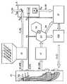
Der Feuerraum FR eines Kraftwerks oder einer anderen technischen Anlage, in der ein Verbrennungsprozess stattfindet, ist mit einem räumlich auflösenden Messsystem (in der Figur mit MS bezeichnet) ausgerüstet. Dabei kann es sich um beliebige Messsysteme handeln, mit dessen Hilfe Messdaten aus der unmittelbaren Nähe der Verbrennung zur Verfügung gestellt werden. Beispiele für solche Messsysteme sind:
- Feuerraumkameras, mit deren Hilfe der Verbrennungsvorgang im Feuerraum erfasst werden kann. Dabei werden durch eine Spektralanalyse des von den Flammen emittierten Lichts zusätzliche Informationen über die Verbrennung gewonnen.
- Anordnung aus Lasern und entsprechenden Detektoren. Hierbei werden Laserstrahlen durch den Feuerraum auf Photodetektoren geleitet. Die Spektralanalyse, der aus dem Feuerraum wieder austretenden Laserstrahlen liefert aufgrund der Absorption bestimmter Wellenlängen eine Information über die Verbrennung selbst. Werden die Laserstrahlen gitterförmig auf mehreren Wegen durch den Feuerraum geschickt, kann die Messinformation räumlich aufgelöst werden.
- Combustion chamber cameras with the aid of which the combustion process in the combustion chamber can be detected. In this case, additional information about the combustion is obtained by a spectral analysis of the light emitted by the flames.
- Arrangement of lasers and corresponding detectors. Here, laser beams are directed through the firebox on photodetectors. The spectral analysis of the laser beam emerging from the combustion chamber again provides information about the combustion itself due to the absorption of certain wavelengths. If the laser beams are sent in lattice form on several paths through the combustion chamber, the measurement information can be spatially resolved.
Entscheidend bei der Auswahl der Messtechnik ist, dass sie zur Bestimmung von wesentlichen Eigenschaften der Verbrennung mit räumlicher Auflösung geeignet ist. Messungen werden dabei beispielsweise auf einem Querschnitt des Feuerraums nahe des Verbrennungsvorgangs durchgeführt. Die ermittelten Messwerte charakterisieren die Verbrennung anhand von Eigenschaften wie beispielsweise lokale Konzentrationen (CO, 02, C02, H20,...) und Temperatur.Decisive in the selection of the measurement technique is that it is suitable for determining essential properties of the combustion with spatial resolution. Measurements are carried out, for example, on a cross section of the combustion chamber near the combustion process. The measured values characterize combustion based on properties such as local concentrations (CO, 02, C02, H20, ...) and temperature.
In allen Fällen erhält man eine Vielzahl unterschiedlichster Messwerte in Abhängigkeit von räumlichen Koordinaten. Am Eingang des erfindungsgemäßen Regelungssystems liegen somit nicht einzelne Messwerte, sondern ganze Messwertverteilungen ähnlich einem zwei- oder dreidimensionalen Muster, an.In all cases, a large number of different measured values are obtained as a function of spatial coordinates. Thus, not individual measured values but entire measured value distributions similar to a two- or three-dimensional pattern are present at the input of the control system according to the invention.
Im Rahmen einer Variablentransformation VT werden diese in der Figur durch M Messwerte MW gekennzeichneten Daten in einem ersten Schritt in regelungstechnisch verwertbare Zustandsgrößen umgewandelt. Die räumliche Information über den Brennraum wird hierbei auf einzelne Kennzahlen abgebildet und somit verdichtet.In the context of a variable transformation VT, these data, which are identified by M measured values MW in the figure, are converted in a first step into state variables that can be used in terms of control technology. The spatial information about the combustion chamber is mapped to individual key figures and thus condensed.
Für die Ableitung der verschiedenen Zustandsgrößen aus der räumlichen Messinformation werden typischerweise folgende Punkte ausgewertet:
- a) Gewichtete Mittelwerte mit Betonung bzw. Unterdrückung von Teilen des messtechnisch erfassten Raumes,
- b) der Mittelwert der Messgröße über den messtechnisch erfassten Raum.
- c) Räumliche Lage des Schwerpunkts der Messwerte,
- d) Statistische Kennzahlen für räumliche Verteilungsmuster.
- a) Weighted averages with emphasis or suppression of parts of the metrologically recorded space,
- b) the mean value of the measurand over the metrologically recorded space.
- c) spatial position of the center of gravity of the measured values,
- d) Statistical key figures for spatial distribution patterns.
Für die regelungstechnisch verwertbaren Zustandsgrößen kann ein Optimierungsziel als Sollwert definiert werden. Außerdem charakterisieren diese Zustandsgrößen in Verbindung mit herkömmlichen, leittechnisch verfügbaren Mess- und Prozessinformationen den aktuellen Betriebszustand des Verbrennungsprozesses.For the controllable state variables, an optimization target can be defined as a setpoint. In addition, these state variables in combination with conventional, process technology available measurement and process information characterize the current operating state of the combustion process.
Durch die beschriebene Variablentransformation VT wird demnach eine beliebige Anzahl von M Messwerten MW in eine wiederum beliebige Anzahl von N Regelgrößen RG umgewandelt, wobei M und N natürliche Zahlen darstellen und N üblicherweise kleiner als M ist. Bei den Regelgrößen RG handelt es sich um Zustandsgrößen, die anschließend als Istwerte für einzelne Regler verwendet werden.Accordingly, the described variable transformation VT converts any desired number of M measured values MW into an arbitrary number of N controlled variables RG, where M and N represent natural numbers and N is usually smaller than M. The control variables RG are state variables which are then used as actual values for individual controllers.
Die N Regelgrößen werden N Reglern R zugeführt. Dies ist in der Figur anhand des Regelbausteins, der einen Subtrahierer und weitere regelungstechnische Bausteine wie beispielsweise einen PI-Regler enthält, dargestellt. Es handelt sich hierbei um einen herkömmlichen Regelbaustein, der ggfs. in der zu regelnden technischen Anlage bereits vorhanden ist. Es kann sich auch um einen Mehrgrößenregelbaustein handeln, je nach Ausführungsvariante. Der hier betrachtete Regelbaustein weist ferner einen Eingang ESW für den Sollwert der abgeleiteten Zustandsgröße auf. Dieser wird entweder manuell vorgegeben, ist konstant oder lastabhängig vorgegeben und soll das gewünschte Betriebsverhalten charakterisieren. Weiterhin existiert neben dem Eingang ERG für die Regelgröße RG ein weiterer Eingang EPG für weitere beliebige Prozessmessgrößen PG, die außerhalb des räumlich auflösenden Messsystems erfasst werden. Innerhalb des Reglers wird die Regeldifferenz zwischen dem Soll- und Istwert gebildet, die Regeldifferenz durch die weiteren Prozessmessgrößen variiert, z.B. zur Anpassung der Reglerverstärkung in Abhängigkeit der aktuellen Lastsituation, und dem vorhandenen Regler (hier PI-Regler) zugeführt, der die notwendigen Stellgrößenänderungen ermittelt. Dieses Signal liegt am Ausgang ARA des Reglers an.The N controlled variables are fed to N regulators R. This is shown in the figure by means of the control module, which contains a subtractor and further control technology components such as a PI controller. This is a conventional control module that may already be present in the technical system to be controlled. It can also be a multi-variable control module, depending on the design variant. The control block considered here also has an input ESW for the desired value of the derived state variable. This is either specified manually, is given constant or load-dependent and should characterize the desired operating behavior. Still exists In addition to the input ERG for the controlled variable RG another input EPG for any other process variables PG, which are detected outside of the spatially resolving measuring system. Within the controller, the control difference between the setpoint and actual value is formed, the control difference by the other process variables varies, for example, to adjust the controller gain as a function of the current load situation, and the existing controller (here PI) supplied, which determines the necessary manipulated variable changes , This signal is present at the output ARA of the controller.
Sind nun N Regler vorhanden, so existieren an dieser Stelle N Werte für die Regelausgänge RA (vgl. Figur). Es gilt nun, in einer Rücktransformation RT diese als Regelausgänge bezeichneten Signale RA der Anzahl N derart umzuwandeln, dass eine bestimmte Anzahl von K Stellgliedern jeweils das Stellsignal erhält, das zur Erreichung des Regelziels notwendig ist. Mit anderen Worten müssen aus den Regelausgängen RA der N Regler R nun Regeleingriffe für verschiedene Stellglieder abgeleitet werden, mit denen der Verbrennungsprozess günstig beeinflusst werden kann. Hierbei kann ein Regeleingriff auf mehrere Stellglieder in differenzierter Stärke erfolgen.If there are N controllers, there are N values for the control outputs RA (see figure). It now applies, in a back transformation RT, to convert these signals RA, designated as control outputs, of the number N in such a way that a certain number of K actuators each receive the actuating signal necessary to achieve the control target. In other words, the control outputs RA of the N controllers R must now be used to derive control interventions for various actuators with which the combustion process can be favorably influenced. In this case, a control intervention can be made on a plurality of actuators in differentiated strength.
Stellglieder sind beispielsweise die Öffnungen von im Verbrennungsraum angeordneten Luftklappen.
In der Berechnungseinheit RT findet die Aufteilung von N Regelausgängen auf K Stellglieder statt (N, K jeweils natürliche Zahlen). Hierbei werden auch Prozessmessgrößen PG berücksichtigt, die außerhalb des räumlich auflösenden Messsystems erfasst werden. Bei der Rücktransformation der Reglerausgänge auf die vorhandenen Stellgrößen ist es von besonderem Vorteil, dass die Aufteilung der Reglerausgänge auf die Stellglieder auf optimale Art und Weise durchgeführt wird, so dass z.B. eine Minimierung der Emissionswerte stattfinden kann und aber gleichzeitig ein möglichst hoher Wirkungsgrad der Anlage erreicht wird. Dies wird in diesem Ausführungsbeispiel dadurch erreicht, dass der Berechnungseinheit RT auch Optimierungswerte OW aus dem Optimierer OPT zugeführt werden. Der Optimierer erhält Informationen aus unterschiedlichen Bereichen.Actuators are, for example, the openings of the combustion chamber arranged louvers.
In the calculation unit RT, the distribution of N control outputs to K actuators takes place (N, K each natural numbers). In this process process variables PG are taken into account, which are recorded outside the spatially resolving measuring system. In the inverse transformation of the controller outputs on the existing control variables, it is of particular advantage that the distribution of the controller outputs is performed on the actuators in an optimal manner, so that, for example, a minimization of emissions can take place and at the same time the highest possible efficiency of the system becomes. This is achieved in this exemplary embodiment in that the calculation unit RT also has optimization values OW from the optimizer OPT be supplied. The optimizer receives information from different areas.
Neben Prozessmessgrößen, die außerhalb des räumlich auflösenden Messsystems erfasst werden, kann der Optimierer ebenfalls Messergebnisse der im Verbrennungsraum angeordneten räumlich auflösenden Messeinrichtungen erhalten. Im Rahmen der Variablentransformation VT' wird eine Anzahl M' der räumlich aufgelösten Messwerte in eine beliebige Anzahl N' von Zustandsgrößen umgewandelt, welche dem Optimierer OPT zugeführt werden. Es kann sich dabei um die gleichen Messwerte handeln wie weiter oben beschrieben, alternativ können auch andere Messwerte verwendet werden. Optional kann der Optimierer OPT mit einem neuronalen Netz NN verbunden sein.
In diesem Fall wird eine hybride Regelstruktur aus herkömmlichen Regelbausteinen sowie neuronalen Netzen erreicht. Das Neuronale Netz wird mit Prozessmessgrößen trainiert und dient als spezifisches Modell zur Vorhersage des Verhaltens der Feuerung. Ein iterativer Optimierungsalgorithmus bestimmt anhand der vom Neuronalen Netz vorhergesagten Feuerungsreaktion die optimale Verteilung der Regeleingriffe auf die Stellglieder sowie Korrekturwerte für die Stellglieder. Dadurch wird der Prozess entsprechend einer vorgegebenen Zielfunktion optimiert.In addition to process variables that are recorded outside of the spatially resolving measuring system, the optimizer can also obtain measurement results of spatially resolving measuring devices arranged in the combustion chamber. In the context of the variable transformation VT ', a number M' of the spatially resolved measured values is converted into any number N 'of state variables which are fed to the optimizer OPT. These may be the same measurements as described above, but other measurements may be used as well. Optionally, the optimizer OPT may be connected to a neural network NN.
In this case, a hybrid control structure of conventional control blocks and neural networks is achieved. The neural network is trained with process measures and serves as a specific model for predicting the behavior of the furnace. An iterative optimization algorithm determines the optimum distribution of the control actions on the actuators and correction values for the actuators based on the firing reaction predicted by the neural network. This optimizes the process according to a given target function.
Bei den Optimierungswerten OW kann es sich beispielsweise auch um Trimmfaktoren handeln. Mittels der Trimmfaktoren werden die Ergebnisse der Rücktransformation RT unter Berücksichtigung des Optimierungsprozesses entsprechend des gewünschten Regelungsziels gewichtet, verschoben und angepasst.The optimization values OW can, for example, also be trim factors. By means of the trimming factors, the results of the back transformation RT are weighted, shifted and adjusted in accordance with the optimization process in accordance with the desired control target.
Anhand der Ausgabewerte der Rücktransformation und gegebenenfalls unter weiterer Berücksichtigung der Ergebnisse aus dem Optimierungsprozess findet abschließend eine Gesamtstellgrößenberechnung GSB für die vorhandenen K Stellglieder statt. Die unterschiedlichen Regeleingriffe auf verschiedene Stellglieder von verschiedenen identifizierten Sollwertabweichungen überlagern sich additiv zu einem Gesamtregeleingriff für jedes Stellglied. Am Ende des Algorithmus werden K Stellgrößenänderungen ST an die einzelnen Stellglieder wie Luftklappen oder Brennstoffzufuhreinrichtungen weitergeleitet.On the basis of the output values of the inverse transformation and, if appropriate, with further consideration of the results from the optimization process, finally, a total manipulated variable calculation GSB for the existing K actuators takes place. The different control interventions on different actuators from different identified setpoint deviations are superimposed additively to a total control intervention for each actuator. At the end of the algorithm K manipulated variable changes ST are forwarded to the individual actuators such as air dampers or fuel supply devices.
Während des gesamten Regelungsverfahrens werden Geschwindigkeit und Größe der einzelnen Regeleingriffe an die gegebenen technischen Randbedingungen und Grenzen der technischen Anlage angepasst. Vom Prozess vorgegebene Grenzen werden nicht überschritten.During the entire control procedure, the speed and size of the individual control interventions are adapted to the given technical boundary conditions and limits of the technical system. The limits specified by the process are not exceeded.
Claims (13)
- Method for controlling a combustion process, in particular in a firing chamber (FR) of a fossil-fuel-fired steam generator, wherein spatially resolved measured values (MW) are determined in the firing chamber (FR),
wherein- an arbitrary number of M measured values (MW) is converted with the aid of a variable transformation (VT) in which the spatial information about the combustion chamber is mapped to individual characteristic parameters and consequently compressed into a number of N less than M controlled variables (RG), the controlled variables corresponding to state variables which can be used for closed-loop control purposes and which are subsequently supplied as actual values to N control loops (R),and wherein- manipulated variable changes (RA) determined in the N control loops (R) are distributed among K actuating elements in an inverse transformation (RT) taking into account an optimization target, where M, N and K are natural numbers. - Method according to claim 1,
wherein in the variable transformation (VT, VT') in order to determine the different state variables from the spatial measured values (MW, MW') reference variables from the following group of reference variables are evaluated:a) Weighted average values with accentuation or suppression of parts of the space registered by the measurement technology means, and/orb) the average value of the measured variable over the space registered by the measurement technology means, and/orc) spatial position of the centre of mass of the measured values, and/ord) statistical characteristic parameters for spatial distribution patterns. - Method according to claim 1 or 2,
wherein an optimization target can be defined as a setpoint value (SW) for the state variables, the state variables, in conjunction with conventionally available measurement and process information, characterize the current operating status of the combustion process. - Method according to one of the preceding claims, wherein setpoint values (SW) for the derived state variables are defined in order to specify the desired operating behaviour.
- Method according to one of the preceding claims, wherein control interventions are derived for different manipulated variables, the combustion process being influenced in a targeted manner by means of said control interventions, wherein a control intervention acts on a plurality of actuating elements at different degrees of intensity.
- Method according to one of the preceding claims, wherein setpoint value deviations are calculated in order to identify deviations for corrective closed-loop control interventions in the process.
- Method according to one of the preceding claims, wherein different control interventions applied to different actuating elements by different identified setpoint value deviations are superimposed additively on one another to produce an overall control intervention for each actuating element.
- Method according to one of claims 1 to 7,
wherein in order to achieve the optimization target a neural network is trained with measured process variables and used as a specific model for predicting the firing behaviour. - Method according to claim 8,
wherein on the basis of the firing response predicted by the neural network a beneficial distribution of the control interventions among the actuating elements as well as correction values for the actuating elements are determined by means of an iterative optimization algorithm. - Method according to one of the preceding claims, wherein the measurement is carried out on a cross-section of the firing chamber close to the combustion zone.
- Method according to one of the preceding claims, wherein the local concentrations of CO, O2, CO2, H2O and the temperature or subgroups of these or comparable measured variables are determined as characteristic properties of the combustion.
- Combustion system having a firing chamber, in particular for a fossil-fuel-fired steam generator, comprising a closed-loop control system having a combustion diagnosis unit, the combustion diagnosis unit being equipped with a spatially resolving measurement system in the firing chamber,
characterised in that
the closed-loop control system is embodied for performing the method according to one of claims 1 to 11. - Fossil-fuel-fired power plant installation having a combustion system according to claim 12.
Applications Claiming Priority (2)
| Application Number | Priority Date | Filing Date | Title |
|---|---|---|---|
| DE102009030322ADE102009030322A1 (en) | 2009-06-24 | 2009-06-24 | Concept for controlling and optimizing the combustion of a steam generator on the basis of spatially resolved measurement information from the combustion chamber |
| PCT/EP2010/058878WO2010149687A2 (en) | 2009-06-24 | 2010-06-23 | Method for controlling a combustion process, in particular in a combustion chamber of a fossil-fueled steam generator, and combustion system |
Publications (2)
| Publication Number | Publication Date |
|---|---|
| EP2446193A2 EP2446193A2 (en) | 2012-05-02 |
| EP2446193B1true EP2446193B1 (en) | 2014-05-07 |
Family
ID=43217810
Family Applications (1)
| Application Number | Title | Priority Date | Filing Date |
|---|---|---|---|
| EP10729831.7ANot-in-forceEP2446193B1 (en) | 2009-06-24 | 2010-06-23 | Method for controlling a combustion process, in particular in a combustion chamber of a fossil-fueled steam generator, and combustion system |
Country Status (11)
| Country | Link |
|---|---|
| US (1) | US9360209B2 (en) |
| EP (1) | EP2446193B1 (en) |
| CN (1) | CN102460018B (en) |
| AU (1) | AU2010264723B2 (en) |
| BR (1) | BRPI1012684A2 (en) |
| CA (1) | CA2766458C (en) |
| DE (1) | DE102009030322A1 (en) |
| ES (1) | ES2465068T3 (en) |
| MX (1) | MX2012000184A (en) |
| RU (1) | RU2523931C2 (en) |
| WO (1) | WO2010149687A2 (en) |
Cited By (1)
| Publication number | Priority date | Publication date | Assignee | Title |
|---|---|---|---|---|
| DE102022106628A1 (en) | 2022-03-22 | 2023-09-28 | Uniper Technologies GmbH | Method for predicting process engineering process values of an incineration plant using a trained neural network |
Families Citing this family (8)
| Publication number | Priority date | Publication date | Assignee | Title |
|---|---|---|---|---|
| CN103032887B (en)* | 2012-12-31 | 2015-02-04 | 河南省电力公司电力科学研究院 | Method for realizing energy-saving running of coal burning boiler |
| CN103615735B (en)* | 2013-11-27 | 2017-02-01 | 广东电网公司电力科学研究院 | Simulation monitoring method of premixed combustion of foamed ceramic burner |
| CN103615736A (en)* | 2013-11-27 | 2014-03-05 | 广东电网公司电力科学研究院 | Simulation monitoring method of thickness of flame area of foamed ceramic burner |
| DE102015203978A1 (en)* | 2015-03-05 | 2016-09-08 | Stg Combustion Control Gmbh & Co. Kg | Method for the controlled operation of a, in particular regenerative, heated industrial furnace, control and regulating device and heatable industrial furnace |
| US10920982B2 (en)* | 2015-09-28 | 2021-02-16 | Schlumberger Technology Corporation | Burner monitoring and control systems |
| RU2713850C1 (en)* | 2018-12-10 | 2020-02-07 | Федеральное государственное бюджетное учреждение науки Институт теплофизики им. С.С. Кутателадзе Сибирского отделения Российской академии наук (ИТ СО РАН) | Fuel combustion modes monitoring system by means of torch images analysis using classifier based on convolutional neural network |
| RU2715302C1 (en)* | 2018-12-10 | 2020-02-26 | Федеральное государственное бюджетное учреждение науки Институт теплофизики им. С.С. Кутателадзе Сибирского отделения Российской академии наук (ИТ СО РАН) | Automatic system for diagnosing combustion of pulverized coal fuel in a combustion chamber |
| CN111895399B (en)* | 2020-08-31 | 2025-04-18 | 北京天地融创科技股份有限公司 | A dual-channel reverse-jet swirl burner and its use method |
Family Cites Families (19)
| Publication number | Priority date | Publication date | Assignee | Title |
|---|---|---|---|---|
| EP0524317A4 (en)* | 1991-02-08 | 1995-02-15 | Tokyo Shibaura Electric Co | Model forecasting controller |
| DE4220149C2 (en)* | 1992-06-19 | 2002-06-13 | Steinmueller Gmbh L & C | Method for regulating the combustion of waste on a grate of a furnace and device for carrying out the method |
| US5408406A (en)* | 1993-10-07 | 1995-04-18 | Honeywell Inc. | Neural net based disturbance predictor for model predictive control |
| US5493631A (en)* | 1993-11-17 | 1996-02-20 | Northrop Grumman Corporation | Stabilized adaptive neural network based control system |
| DE19509412C2 (en)* | 1995-03-15 | 1997-01-30 | Siemens Ag | Method and device for controlling the firing of a steam generator system |
| US5822740A (en)* | 1996-06-28 | 1998-10-13 | Honeywell Inc. | Adaptive fuzzy controller that modifies membership functions |
| DE19710206A1 (en)* | 1997-03-12 | 1998-09-17 | Siemens Ag | Method and device for combustion analysis and flame monitoring in a combustion chamber |
| DE19841877A1 (en) | 1998-09-11 | 2000-04-20 | Siemens Ag | Method and device for determining the soot loading of a combustion chamber |
| US6532454B1 (en)* | 1998-09-24 | 2003-03-11 | Paul J. Werbos | Stable adaptive control using critic designs |
| US6553924B2 (en)* | 1998-10-19 | 2003-04-29 | Eco/Technologies, Llc | Co-combustion of waste sludge in municipal waste combustors and other furnaces |
| NL1013209C2 (en)* | 1999-10-04 | 2001-04-05 | Tno | Control system for an incineration plant, such as a waste incineration plant. |
| DE19948377C1 (en) | 1999-10-07 | 2001-05-23 | Siemens Ag | Method and device for determining and regulating the excess air in a combustion process |
| CH694823A5 (en)* | 2000-12-08 | 2005-07-29 | Von Roll Umwelttechnik Ag | A method for operating an incinerator. |
| EP1543394B1 (en) | 2002-09-26 | 2006-05-17 | Siemens Aktiengesellschaft | Method and device for monitoring a technical installation comprising several systems, in particular an electric power station |
| US7581945B2 (en)* | 2005-11-30 | 2009-09-01 | General Electric Company | System, method, and article of manufacture for adjusting CO emission levels at predetermined locations in a boiler system |
| PL1850069T3 (en) | 2006-04-25 | 2009-01-30 | Powitec Intelligent Tech Gmbh | Method and Control Loop for Controlling a Combustion Process |
| MX2008014186A (en)* | 2006-05-05 | 2009-02-25 | Plascoenergy Ip Holdings Slb | A control system for the conversion of a carbonaceous feedstock into gas. |
| DE102006022626B4 (en)* | 2006-05-12 | 2010-09-02 | Rwe Power Ag | Method of operating a coal-fired steam generator |
| US8219247B2 (en)* | 2009-11-19 | 2012-07-10 | Air Products And Chemicals, Inc. | Method of operating a furnace |
- 2009
- 2009-06-24DEDE102009030322Apatent/DE102009030322A1/ennot_activeCeased
- 2010
- 2010-06-23USUS13/378,727patent/US9360209B2/enactiveActive
- 2010-06-23MXMX2012000184Apatent/MX2012000184A/enactiveIP Right Grant
- 2010-06-23RURU2012102271/06Apatent/RU2523931C2/ennot_activeIP Right Cessation
- 2010-06-23WOPCT/EP2010/058878patent/WO2010149687A2/enactiveApplication Filing
- 2010-06-23EPEP10729831.7Apatent/EP2446193B1/ennot_activeNot-in-force
- 2010-06-23BRBRPI1012684Apatent/BRPI1012684A2/ennot_activeIP Right Cessation
- 2010-06-23ESES10729831.7Tpatent/ES2465068T3/enactiveActive
- 2010-06-23AUAU2010264723Apatent/AU2010264723B2/ennot_activeCeased
- 2010-06-23CACA2766458Apatent/CA2766458C/ennot_activeExpired - Fee Related
- 2010-06-23CNCN201080036258.7Apatent/CN102460018B/enactiveActive
Cited By (1)
| Publication number | Priority date | Publication date | Assignee | Title |
|---|---|---|---|---|
| DE102022106628A1 (en) | 2022-03-22 | 2023-09-28 | Uniper Technologies GmbH | Method for predicting process engineering process values of an incineration plant using a trained neural network |
Also Published As
| Publication number | Publication date |
|---|---|
| CA2766458A1 (en) | 2010-12-29 |
| EP2446193A2 (en) | 2012-05-02 |
| CN102460018B (en) | 2016-03-09 |
| RU2523931C2 (en) | 2014-07-27 |
| US20120125003A1 (en) | 2012-05-24 |
| BRPI1012684A2 (en) | 2016-03-29 |
| US9360209B2 (en) | 2016-06-07 |
| AU2010264723A1 (en) | 2012-01-19 |
| WO2010149687A2 (en) | 2010-12-29 |
| CN102460018A (en) | 2012-05-16 |
| ES2465068T3 (en) | 2014-06-05 |
| CA2766458C (en) | 2014-10-14 |
| DE102009030322A1 (en) | 2010-12-30 |
| MX2012000184A (en) | 2012-02-28 |
| WO2010149687A3 (en) | 2011-03-03 |
| RU2012102271A (en) | 2013-07-27 |
| AU2010264723B2 (en) | 2013-02-21 |
Similar Documents
| Publication | Publication Date | Title |
|---|---|---|
| EP2446193B1 (en) | Method for controlling a combustion process, in particular in a combustion chamber of a fossil-fueled steam generator, and combustion system | |
| EP0897086B1 (en) | Method for determining the average radiation of a burner bed in an incinerating plant and for the control of the combustion process | |
| EP0696708B1 (en) | Method for controlling the burning in combustion plants, especially waste incineration plants | |
| DE102012100261A1 (en) | Stoichiometric exhaust gas recirculation and associated combustion control | |
| EP2920515B1 (en) | Cfd simulation of a combustion chamber with a plurality of burners with separate consideration of the fuel and air components originating from each burner | |
| WO2009013136A1 (en) | Method for operating a combustion device, and combustion device for carrying out the method | |
| DE112007002909T5 (en) | Coal-fired boiler device | |
| DE102011079325A1 (en) | Method for controlling the air number of a burner | |
| EP3663648A1 (en) | Method and device for regulating the mixing ratio of combustion air and combustion gas in a combustion process | |
| DE102004036911A1 (en) | Operating procedure for a combustion plant | |
| DE102006015230A1 (en) | combustion chamber | |
| DE102014115726A1 (en) | STEAM TEMPERATURE CONTROL USING A MODEL-BASED TEMPERATURE COMPENSATION | |
| EP0499976B1 (en) | Method for operating an incineration plant | |
| EP4058727B1 (en) | Method for controlling the combustion in furnace systems | |
| DE3607386C2 (en) | ||
| EP3964752B1 (en) | Method for operating a combustion plant | |
| DE2718520A1 (en) | METHOD FOR AUTOMATICALLY CONTROLLING COMBUSTION IN A FIRE AND CORRESPONDING FIRE | |
| EP1687566A2 (en) | Device and method for optimizing the exhaust gas burn-out rate in incinerating plants | |
| EP2730842B1 (en) | Heating device and method for optimised combustion of biomass | |
| AT412903B (en) | METHOD FOR CONTROLLING BZW. CONTROL OF FUELING SYSTEMS AND THEREBY REGULATORY FIRING SYSTEM | |
| EP3861256B1 (en) | A method and device for regulating a process within a system, in particular a combustion process in a power station | |
| EP2920517B1 (en) | Apparatus and method for measuring the combustiongrade of a particle in a furnace | |
| DE19712771C2 (en) | Method and arrangement for automatic combustion control in boilers | |
| EP4155608A1 (en) | Method for detecting a burner flame extinguishment | |
| DD234915A1 (en) | PROCESS FOR THE COMBUSTION OPTIMAL POWER CONTROL OF STEAM GENERATORS WITH RUST FIRES |
Legal Events
| Date | Code | Title | Description |
|---|---|---|---|
| PUAI | Public reference made under article 153(3) epc to a published international application that has entered the european phase | Free format text:ORIGINAL CODE: 0009012 | |
| 17P | Request for examination filed | Effective date:20111216 | |
| AK | Designated contracting states | Kind code of ref document:A2 Designated state(s):AL AT BE BG CH CY CZ DE DK EE ES FI FR GB GR HR HU IE IS IT LI LT LU LV MC MK MT NL NO PL PT RO SE SI SK SM TR | |
| DAX | Request for extension of the european patent (deleted) | ||
| RAP1 | Party data changed (applicant data changed or rights of an application transferred) | Owner name:SIEMENS AKTIENGESELLSCHAFT | |
| RIC1 | Information provided on ipc code assigned before grant | Ipc:F23D 1/02 20060101AFI20130205BHEP Ipc:F23N 5/02 20060101ALI20130205BHEP Ipc:F23N 5/00 20060101ALI20130205BHEP | |
| GRAP | Despatch of communication of intention to grant a patent | Free format text:ORIGINAL CODE: EPIDOSNIGR1 | |
| INTG | Intention to grant announced | Effective date:20131206 | |
| GRAS | Grant fee paid | Free format text:ORIGINAL CODE: EPIDOSNIGR3 | |
| GRAA | (expected) grant | Free format text:ORIGINAL CODE: 0009210 | |
| AK | Designated contracting states | Kind code of ref document:B1 Designated state(s):AL AT BE BG CH CY CZ DE DK EE ES FI FR GB GR HR HU IE IS IT LI LT LU LV MC MK MT NL NO PL PT RO SE SI SK SM TR | |
| REG | Reference to a national code | Ref country code:GB Ref legal event code:FG4D Free format text:NOT ENGLISH | |
| REG | Reference to a national code | Ref country code:AT Ref legal event code:REF Ref document number:666992 Country of ref document:AT Kind code of ref document:T Effective date:20140515 | |
| REG | Reference to a national code | Ref country code:IE Ref legal event code:FG4D Free format text:LANGUAGE OF EP DOCUMENT: GERMAN | |
| REG | Reference to a national code | Ref country code:ES Ref legal event code:FG2A Ref document number:2465068 Country of ref document:ES Kind code of ref document:T3 Effective date:20140605 | |
| REG | Reference to a national code | Ref country code:DE Ref legal event code:R096 Ref document number:502010006915 Country of ref document:DE Effective date:20140612 | |
| REG | Reference to a national code | Ref country code:NL Ref legal event code:T3 | |
| REG | Reference to a national code | Ref country code:LT Ref legal event code:MG4D | |
| PG25 | Lapsed in a contracting state [announced via postgrant information from national office to epo] | Ref country code:GR Free format text:LAPSE BECAUSE OF FAILURE TO SUBMIT A TRANSLATION OF THE DESCRIPTION OR TO PAY THE FEE WITHIN THE PRESCRIBED TIME-LIMIT Effective date:20140808 Ref country code:IS Free format text:LAPSE BECAUSE OF FAILURE TO SUBMIT A TRANSLATION OF THE DESCRIPTION OR TO PAY THE FEE WITHIN THE PRESCRIBED TIME-LIMIT Effective date:20140907 Ref country code:FI Free format text:LAPSE BECAUSE OF FAILURE TO SUBMIT A TRANSLATION OF THE DESCRIPTION OR TO PAY THE FEE WITHIN THE PRESCRIBED TIME-LIMIT Effective date:20140507 Ref country code:CY Free format text:LAPSE BECAUSE OF FAILURE TO SUBMIT A TRANSLATION OF THE DESCRIPTION OR TO PAY THE FEE WITHIN THE PRESCRIBED TIME-LIMIT Effective date:20140507 Ref country code:NO Free format text:LAPSE BECAUSE OF FAILURE TO SUBMIT A TRANSLATION OF THE DESCRIPTION OR TO PAY THE FEE WITHIN THE PRESCRIBED TIME-LIMIT Effective date:20140807 Ref country code:LT Free format text:LAPSE BECAUSE OF FAILURE TO SUBMIT A TRANSLATION OF THE DESCRIPTION OR TO PAY THE FEE WITHIN THE PRESCRIBED TIME-LIMIT Effective date:20140507 | |
| PG25 | Lapsed in a contracting state [announced via postgrant information from national office to epo] | Ref country code:LV Free format text:LAPSE BECAUSE OF FAILURE TO SUBMIT A TRANSLATION OF THE DESCRIPTION OR TO PAY THE FEE WITHIN THE PRESCRIBED TIME-LIMIT Effective date:20140507 Ref country code:PL Free format text:LAPSE BECAUSE OF FAILURE TO SUBMIT A TRANSLATION OF THE DESCRIPTION OR TO PAY THE FEE WITHIN THE PRESCRIBED TIME-LIMIT Effective date:20140507 Ref country code:HR Free format text:LAPSE BECAUSE OF FAILURE TO SUBMIT A TRANSLATION OF THE DESCRIPTION OR TO PAY THE FEE WITHIN THE PRESCRIBED TIME-LIMIT Effective date:20140507 Ref country code:SE Free format text:LAPSE BECAUSE OF FAILURE TO SUBMIT A TRANSLATION OF THE DESCRIPTION OR TO PAY THE FEE WITHIN THE PRESCRIBED TIME-LIMIT Effective date:20140507 | |
| PG25 | Lapsed in a contracting state [announced via postgrant information from national office to epo] | Ref country code:PT Free format text:LAPSE BECAUSE OF FAILURE TO SUBMIT A TRANSLATION OF THE DESCRIPTION OR TO PAY THE FEE WITHIN THE PRESCRIBED TIME-LIMIT Effective date:20140908 | |
| REG | Reference to a national code | Ref country code:DE Ref legal event code:R119 Ref document number:502010006915 Country of ref document:DE | |
| PG25 | Lapsed in a contracting state [announced via postgrant information from national office to epo] | Ref country code:DK Free format text:LAPSE BECAUSE OF FAILURE TO SUBMIT A TRANSLATION OF THE DESCRIPTION OR TO PAY THE FEE WITHIN THE PRESCRIBED TIME-LIMIT Effective date:20140507 Ref country code:EE Free format text:LAPSE BECAUSE OF FAILURE TO SUBMIT A TRANSLATION OF THE DESCRIPTION OR TO PAY THE FEE WITHIN THE PRESCRIBED TIME-LIMIT Effective date:20140507 Ref country code:SK Free format text:LAPSE BECAUSE OF FAILURE TO SUBMIT A TRANSLATION OF THE DESCRIPTION OR TO PAY THE FEE WITHIN THE PRESCRIBED TIME-LIMIT Effective date:20140507 Ref country code:RO Free format text:LAPSE BECAUSE OF FAILURE TO SUBMIT A TRANSLATION OF THE DESCRIPTION OR TO PAY THE FEE WITHIN THE PRESCRIBED TIME-LIMIT Effective date:20140507 | |
| REG | Reference to a national code | Ref country code:CH Ref legal event code:PL | |
| PLBE | No opposition filed within time limit | Free format text:ORIGINAL CODE: 0009261 | |
| STAA | Information on the status of an ep patent application or granted ep patent | Free format text:STATUS: NO OPPOSITION FILED WITHIN TIME LIMIT | |
| REG | Reference to a national code | Ref country code:DE Ref legal event code:R119 Ref document number:502010006915 Country of ref document:DE Effective date:20150101 | |
| 26N | No opposition filed | Effective date:20150210 | |
| GBPC | Gb: european patent ceased through non-payment of renewal fee | Effective date:20140807 | |
| PG25 | Lapsed in a contracting state [announced via postgrant information from national office to epo] | Ref country code:DE Free format text:LAPSE BECAUSE OF NON-PAYMENT OF DUE FEES Effective date:20150101 Ref country code:LI Free format text:LAPSE BECAUSE OF NON-PAYMENT OF DUE FEES Effective date:20140630 Ref country code:CH Free format text:LAPSE BECAUSE OF NON-PAYMENT OF DUE FEES Effective date:20140630 | |
| REG | Reference to a national code | Ref country code:FR Ref legal event code:PLFP Year of fee payment:6 | |
| PG25 | Lapsed in a contracting state [announced via postgrant information from national office to epo] | Ref country code:SI Free format text:LAPSE BECAUSE OF FAILURE TO SUBMIT A TRANSLATION OF THE DESCRIPTION OR TO PAY THE FEE WITHIN THE PRESCRIBED TIME-LIMIT Effective date:20140507 Ref country code:GB Free format text:LAPSE BECAUSE OF NON-PAYMENT OF DUE FEES Effective date:20140807 | |
| PGFP | Annual fee paid to national office [announced via postgrant information from national office to epo] | Ref country code:TR Payment date:20150528 Year of fee payment:6 Ref country code:CZ Payment date:20150622 Year of fee payment:6 | |
| PGFP | Annual fee paid to national office [announced via postgrant information from national office to epo] | Ref country code:IT Payment date:20150623 Year of fee payment:6 Ref country code:FR Payment date:20150610 Year of fee payment:6 Ref country code:NL Payment date:20150602 Year of fee payment:6 | |
| PGFP | Annual fee paid to national office [announced via postgrant information from national office to epo] | Ref country code:ES Payment date:20150727 Year of fee payment:6 | |
| PG25 | Lapsed in a contracting state [announced via postgrant information from national office to epo] | Ref country code:MT Free format text:LAPSE BECAUSE OF FAILURE TO SUBMIT A TRANSLATION OF THE DESCRIPTION OR TO PAY THE FEE WITHIN THE PRESCRIBED TIME-LIMIT Effective date:20140507 | |
| REG | Reference to a national code | Ref country code:IE Ref legal event code:MM4A | |
| PG25 | Lapsed in a contracting state [announced via postgrant information from national office to epo] | Ref country code:SM Free format text:LAPSE BECAUSE OF FAILURE TO SUBMIT A TRANSLATION OF THE DESCRIPTION OR TO PAY THE FEE WITHIN THE PRESCRIBED TIME-LIMIT Effective date:20140507 Ref country code:MC Free format text:LAPSE BECAUSE OF FAILURE TO SUBMIT A TRANSLATION OF THE DESCRIPTION OR TO PAY THE FEE WITHIN THE PRESCRIBED TIME-LIMIT Effective date:20140507 | |
| PG25 | Lapsed in a contracting state [announced via postgrant information from national office to epo] | Ref country code:BG Free format text:LAPSE BECAUSE OF FAILURE TO SUBMIT A TRANSLATION OF THE DESCRIPTION OR TO PAY THE FEE WITHIN THE PRESCRIBED TIME-LIMIT Effective date:20140507 | |
| PG25 | Lapsed in a contracting state [announced via postgrant information from national office to epo] | Ref country code:LU Free format text:LAPSE BECAUSE OF NON-PAYMENT OF DUE FEES Effective date:20140623 Ref country code:IE Free format text:LAPSE BECAUSE OF NON-PAYMENT OF DUE FEES Effective date:20140623 Ref country code:BE Free format text:LAPSE BECAUSE OF FAILURE TO SUBMIT A TRANSLATION OF THE DESCRIPTION OR TO PAY THE FEE WITHIN THE PRESCRIBED TIME-LIMIT Effective date:20140630 Ref country code:HU Free format text:LAPSE BECAUSE OF FAILURE TO SUBMIT A TRANSLATION OF THE DESCRIPTION OR TO PAY THE FEE WITHIN THE PRESCRIBED TIME-LIMIT; INVALID AB INITIO Effective date:20100623 | |
| REG | Reference to a national code | Ref country code:AT Ref legal event code:MM01 Ref document number:666992 Country of ref document:AT Kind code of ref document:T Effective date:20150623 | |
| PG25 | Lapsed in a contracting state [announced via postgrant information from national office to epo] | Ref country code:AT Free format text:LAPSE BECAUSE OF NON-PAYMENT OF DUE FEES Effective date:20150623 | |
| PG25 | Lapsed in a contracting state [announced via postgrant information from national office to epo] | Ref country code:CZ Free format text:LAPSE BECAUSE OF NON-PAYMENT OF DUE FEES Effective date:20160623 | |
| REG | Reference to a national code | Ref country code:NL Ref legal event code:MM Effective date:20160701 | |
| REG | Reference to a national code | Ref country code:FR Ref legal event code:ST Effective date:20170228 | |
| PG25 | Lapsed in a contracting state [announced via postgrant information from national office to epo] | Ref country code:FR Free format text:LAPSE BECAUSE OF NON-PAYMENT OF DUE FEES Effective date:20160630 | |
| PG25 | Lapsed in a contracting state [announced via postgrant information from national office to epo] | Ref country code:NL Free format text:LAPSE BECAUSE OF NON-PAYMENT OF DUE FEES Effective date:20160701 | |
| PG25 | Lapsed in a contracting state [announced via postgrant information from national office to epo] | Ref country code:IT Free format text:LAPSE BECAUSE OF NON-PAYMENT OF DUE FEES Effective date:20160623 | |
| PG25 | Lapsed in a contracting state [announced via postgrant information from national office to epo] | Ref country code:ES Free format text:LAPSE BECAUSE OF NON-PAYMENT OF DUE FEES Effective date:20160624 | |
| PG25 | Lapsed in a contracting state [announced via postgrant information from national office to epo] | Ref country code:MK Free format text:LAPSE BECAUSE OF FAILURE TO SUBMIT A TRANSLATION OF THE DESCRIPTION OR TO PAY THE FEE WITHIN THE PRESCRIBED TIME-LIMIT Effective date:20140507 | |
| PG25 | Lapsed in a contracting state [announced via postgrant information from national office to epo] | Ref country code:AL Free format text:LAPSE BECAUSE OF FAILURE TO SUBMIT A TRANSLATION OF THE DESCRIPTION OR TO PAY THE FEE WITHIN THE PRESCRIBED TIME-LIMIT Effective date:20140507 | |
| REG | Reference to a national code | Ref country code:ES Ref legal event code:FD2A Effective date:20181119 | |
| PG25 | Lapsed in a contracting state [announced via postgrant information from national office to epo] | Ref country code:TR Free format text:LAPSE BECAUSE OF NON-PAYMENT OF DUE FEES Effective date:20160623 |