EP2445993B1 - Multistage resid hydrocracking - Google Patents
Multistage resid hydrocrackingDownload PDFInfo
- Publication number
- EP2445993B1 EP2445993B1EP10726674.4AEP10726674AEP2445993B1EP 2445993 B1EP2445993 B1EP 2445993B1EP 10726674 AEP10726674 AEP 10726674AEP 2445993 B1EP2445993 B1EP 2445993B1
- Authority
- EP
- European Patent Office
- Prior art keywords
- resid
- fraction
- stage
- reactor
- hydrocracking
- Prior art date
- Legal status (The legal status is an assumption and is not a legal conclusion. Google has not performed a legal analysis and makes no representation as to the accuracy of the status listed.)
- Active
Links
Images


Classifications
- C—CHEMISTRY; METALLURGY
- C10—PETROLEUM, GAS OR COKE INDUSTRIES; TECHNICAL GASES CONTAINING CARBON MONOXIDE; FUELS; LUBRICANTS; PEAT
- C10G—CRACKING HYDROCARBON OILS; PRODUCTION OF LIQUID HYDROCARBON MIXTURES, e.g. BY DESTRUCTIVE HYDROGENATION, OLIGOMERISATION, POLYMERISATION; RECOVERY OF HYDROCARBON OILS FROM OIL-SHALE, OIL-SAND, OR GASES; REFINING MIXTURES MAINLY CONSISTING OF HYDROCARBONS; REFORMING OF NAPHTHA; MINERAL WAXES
- C10G67/00—Treatment of hydrocarbon oils by at least one hydrotreatment process and at least one process for refining in the absence of hydrogen only
- C10G67/02—Treatment of hydrocarbon oils by at least one hydrotreatment process and at least one process for refining in the absence of hydrogen only plural serial stages only
- C10G67/04—Treatment of hydrocarbon oils by at least one hydrotreatment process and at least one process for refining in the absence of hydrogen only plural serial stages only including solvent extraction as the refining step in the absence of hydrogen
- C10G67/0454—Solvent desasphalting
- C10G67/049—The hydrotreatment being a hydrocracking
- C—CHEMISTRY; METALLURGY
- C10—PETROLEUM, GAS OR COKE INDUSTRIES; TECHNICAL GASES CONTAINING CARBON MONOXIDE; FUELS; LUBRICANTS; PEAT
- C10G—CRACKING HYDROCARBON OILS; PRODUCTION OF LIQUID HYDROCARBON MIXTURES, e.g. BY DESTRUCTIVE HYDROGENATION, OLIGOMERISATION, POLYMERISATION; RECOVERY OF HYDROCARBON OILS FROM OIL-SHALE, OIL-SAND, OR GASES; REFINING MIXTURES MAINLY CONSISTING OF HYDROCARBONS; REFORMING OF NAPHTHA; MINERAL WAXES
- C10G21/00—Refining of hydrocarbon oils, in the absence of hydrogen, by extraction with selective solvents
- C10G21/003—Solvent de-asphalting
- C—CHEMISTRY; METALLURGY
- C10—PETROLEUM, GAS OR COKE INDUSTRIES; TECHNICAL GASES CONTAINING CARBON MONOXIDE; FUELS; LUBRICANTS; PEAT
- C10G—CRACKING HYDROCARBON OILS; PRODUCTION OF LIQUID HYDROCARBON MIXTURES, e.g. BY DESTRUCTIVE HYDROGENATION, OLIGOMERISATION, POLYMERISATION; RECOVERY OF HYDROCARBON OILS FROM OIL-SHALE, OIL-SAND, OR GASES; REFINING MIXTURES MAINLY CONSISTING OF HYDROCARBONS; REFORMING OF NAPHTHA; MINERAL WAXES
- C10G47/00—Cracking of hydrocarbon oils, in the presence of hydrogen or hydrogen- generating compounds, to obtain lower boiling fractions
- C—CHEMISTRY; METALLURGY
- C10—PETROLEUM, GAS OR COKE INDUSTRIES; TECHNICAL GASES CONTAINING CARBON MONOXIDE; FUELS; LUBRICANTS; PEAT
- C10G—CRACKING HYDROCARBON OILS; PRODUCTION OF LIQUID HYDROCARBON MIXTURES, e.g. BY DESTRUCTIVE HYDROGENATION, OLIGOMERISATION, POLYMERISATION; RECOVERY OF HYDROCARBON OILS FROM OIL-SHALE, OIL-SAND, OR GASES; REFINING MIXTURES MAINLY CONSISTING OF HYDROCARBONS; REFORMING OF NAPHTHA; MINERAL WAXES
- C10G67/00—Treatment of hydrocarbon oils by at least one hydrotreatment process and at least one process for refining in the absence of hydrogen only
- C—CHEMISTRY; METALLURGY
- C10—PETROLEUM, GAS OR COKE INDUSTRIES; TECHNICAL GASES CONTAINING CARBON MONOXIDE; FUELS; LUBRICANTS; PEAT
- C10G—CRACKING HYDROCARBON OILS; PRODUCTION OF LIQUID HYDROCARBON MIXTURES, e.g. BY DESTRUCTIVE HYDROGENATION, OLIGOMERISATION, POLYMERISATION; RECOVERY OF HYDROCARBON OILS FROM OIL-SHALE, OIL-SAND, OR GASES; REFINING MIXTURES MAINLY CONSISTING OF HYDROCARBONS; REFORMING OF NAPHTHA; MINERAL WAXES
- C10G2300/00—Aspects relating to hydrocarbon processing covered by groups C10G1/00 - C10G99/00
- C10G2300/10—Feedstock materials
- C10G2300/107—Atmospheric residues having a boiling point of at least about 538 °C
- C—CHEMISTRY; METALLURGY
- C10—PETROLEUM, GAS OR COKE INDUSTRIES; TECHNICAL GASES CONTAINING CARBON MONOXIDE; FUELS; LUBRICANTS; PEAT
- C10G—CRACKING HYDROCARBON OILS; PRODUCTION OF LIQUID HYDROCARBON MIXTURES, e.g. BY DESTRUCTIVE HYDROGENATION, OLIGOMERISATION, POLYMERISATION; RECOVERY OF HYDROCARBON OILS FROM OIL-SHALE, OIL-SAND, OR GASES; REFINING MIXTURES MAINLY CONSISTING OF HYDROCARBONS; REFORMING OF NAPHTHA; MINERAL WAXES
- C10G2300/00—Aspects relating to hydrocarbon processing covered by groups C10G1/00 - C10G99/00
- C10G2300/10—Feedstock materials
- C10G2300/1077—Vacuum residues
- C—CHEMISTRY; METALLURGY
- C10—PETROLEUM, GAS OR COKE INDUSTRIES; TECHNICAL GASES CONTAINING CARBON MONOXIDE; FUELS; LUBRICANTS; PEAT
- C10G—CRACKING HYDROCARBON OILS; PRODUCTION OF LIQUID HYDROCARBON MIXTURES, e.g. BY DESTRUCTIVE HYDROGENATION, OLIGOMERISATION, POLYMERISATION; RECOVERY OF HYDROCARBON OILS FROM OIL-SHALE, OIL-SAND, OR GASES; REFINING MIXTURES MAINLY CONSISTING OF HYDROCARBONS; REFORMING OF NAPHTHA; MINERAL WAXES
- C10G2300/00—Aspects relating to hydrocarbon processing covered by groups C10G1/00 - C10G99/00
- C10G2300/20—Characteristics of the feedstock or the products
- C10G2300/201—Impurities
- C10G2300/202—Heteroatoms content, i.e. S, N, O, P
- C—CHEMISTRY; METALLURGY
- C10—PETROLEUM, GAS OR COKE INDUSTRIES; TECHNICAL GASES CONTAINING CARBON MONOXIDE; FUELS; LUBRICANTS; PEAT
- C10G—CRACKING HYDROCARBON OILS; PRODUCTION OF LIQUID HYDROCARBON MIXTURES, e.g. BY DESTRUCTIVE HYDROGENATION, OLIGOMERISATION, POLYMERISATION; RECOVERY OF HYDROCARBON OILS FROM OIL-SHALE, OIL-SAND, OR GASES; REFINING MIXTURES MAINLY CONSISTING OF HYDROCARBONS; REFORMING OF NAPHTHA; MINERAL WAXES
- C10G2300/00—Aspects relating to hydrocarbon processing covered by groups C10G1/00 - C10G99/00
- C10G2300/20—Characteristics of the feedstock or the products
- C10G2300/201—Impurities
- C10G2300/205—Metal content
- C10G2300/206—Asphaltenes
- C—CHEMISTRY; METALLURGY
- C10—PETROLEUM, GAS OR COKE INDUSTRIES; TECHNICAL GASES CONTAINING CARBON MONOXIDE; FUELS; LUBRICANTS; PEAT
- C10G—CRACKING HYDROCARBON OILS; PRODUCTION OF LIQUID HYDROCARBON MIXTURES, e.g. BY DESTRUCTIVE HYDROGENATION, OLIGOMERISATION, POLYMERISATION; RECOVERY OF HYDROCARBON OILS FROM OIL-SHALE, OIL-SAND, OR GASES; REFINING MIXTURES MAINLY CONSISTING OF HYDROCARBONS; REFORMING OF NAPHTHA; MINERAL WAXES
- C10G2300/00—Aspects relating to hydrocarbon processing covered by groups C10G1/00 - C10G99/00
- C10G2300/20—Characteristics of the feedstock or the products
- C10G2300/30—Physical properties of feedstocks or products
- C10G2300/301—Boiling range
- C—CHEMISTRY; METALLURGY
- C10—PETROLEUM, GAS OR COKE INDUSTRIES; TECHNICAL GASES CONTAINING CARBON MONOXIDE; FUELS; LUBRICANTS; PEAT
- C10G—CRACKING HYDROCARBON OILS; PRODUCTION OF LIQUID HYDROCARBON MIXTURES, e.g. BY DESTRUCTIVE HYDROGENATION, OLIGOMERISATION, POLYMERISATION; RECOVERY OF HYDROCARBON OILS FROM OIL-SHALE, OIL-SAND, OR GASES; REFINING MIXTURES MAINLY CONSISTING OF HYDROCARBONS; REFORMING OF NAPHTHA; MINERAL WAXES
- C10G2300/00—Aspects relating to hydrocarbon processing covered by groups C10G1/00 - C10G99/00
- C10G2300/40—Characteristics of the process deviating from typical ways of processing
- C10G2300/42—Hydrogen of special source or of special composition
Definitions
- the inventionrelates to a process for hydrocracking and deasphalting resid.
- Hydrocarbon compoundsare useful for a number of purposes.
- hydrocarbon compoundsare useful, inter alia, as fuels, solvents, degreasers, cleaning agents, and polymer precursors.
- the most important source of hydrocarbon compoundsis petroleum crude oil. Refining of crude oil into separate hydrocarbon compound fractions is a well-known processing technique.
- Crude oilsrange widely in their composition and physical and chemical properties. Heavy crudes are characterized by a relatively high viscosity, low API gravity, and high percentage of high boiling components (i.e., having a normal boiling point of greater than 510°C (950°F)).
- Refined petroleum productsgenerally have higher average hydrogen to carbon ratios on a molecular basis. Therefore, the upgrading of a petroleum refinery hydrocarbon fraction is generally classified into one of two categories: hydrogen addition and carbon rejection.
- Hydrogen additionis performed by processes such as hydrocracking and hydrotreating.
- Carbon rejection processestypically produce a stream of rejected high carbon material which may be a liquid or a solid; e.g., coke deposits.
- Hydrocracking processescan be used to upgrade higher boiling materials, such as resid, typically present in heavy crude oil by converting them into more valuable lower boiling materials.
- resid feed to a hydrocracking reactormay be converted to a hydrocracking reaction product.
- the unreacted residmay be recovered from the hydrocracking process and either removed or recycled back to the hydrocracking reactor in order to increase the overall resid conversion.
- the resid conversion in a hydrocracking reactorcan depend on a variety of factors, including feedstock composition; the type of reactor used; the reaction severity, including temperature and pressure conditions; reactor space velocity; and catalyst type and performance.
- the reaction severitymay be used to increase the conversion.
- side reactionsmay occur inside the hydrocracking reactor to produce various byproducts in the form of coke precursors, sediments, other deposits as well as byproducts which form a secondary liquid phase. Excessive formation of such sediments can hinder subsequent processing and can deactivate the hydrocracking catalyst by poisoning, coking, or fouling. Deactivation of the hydrocracking catalyst can not only significantly reduce the resid conversion, but can also require more frequent change-outs of expensive catalyst.
- Formation of a secondary liquid phasenot only deactivates the hydrocracking catalyst, but also limits the maximum conversion, thereby resulting in a higher catalyst consumption which can defluidize the catalyst. This leads to formation of "hot zones" within the catalyst bed, exacerbating the formation of coke, which further deactivates the hydrocracking catalyst.
- Sediment formation inside the hydrocracking reactoris also a strong function of the feedstock quality.
- asphaltenes that may be present in the resid feed to the hydrocracking reactor systemare especially prone to forming sediments when subjected to severe operating conditions.
- separation of the asphaltenes from the resid in order to increase the conversionmay be desirable.
- solvent deasphaltingtypically involves physically separating the lighter hydrocarbons and the heavier hydrocarbons including asphaltenes based on their relative affinities for the solvent.
- a light solventsuch as a C 3 to C 7 hydrocarbon can be used to dissolve or suspend the lighter hydrocarbons, commonly referred to as deasphalted oil, allowing the asphaltenes to be precipitated.
- the two phasesare then separated and the solvent is recovered. Additional information on solvent deasphalting conditions, solvents and operations may be obtained from U.S. Patent Nos. 4,239,616 ; 4,440,633 ; 4,354,922 ; 4,354,928 ; and 4,536,283 .
- Moderate overall resid conversionsmay be achieved using such processes, as both the deasphalted oil and the asphaltenes are separately hydrocracked.
- the hydrocracking of asphaltenes as disclosedis at high severity/high conversion, and may present special challenges, as discussed above. For example, operating the asphaltenes hydrocracker at high severity in order to increase the conversion may also cause a high rate of sediment formation, and a high rate of catalyst replacement. In contrast, operating the asphaltenes hydrocracker at low severity will suppress sediment formation, but the per-pass conversion of asphaltenes will be low.
- Residuum hydrocarbon (resid) feedstocks useful in the invention disclosed hereinmay include various heavy crude and refinery fractions.
- resid hydrocarbon feedstocksmay include fresh resid hydrocarbon feeds, petroleum atmospheric or vacuum residue, hydrocracked atmospheric tower or vacuum tower bottoms, straight run vacuum gas oil, hydrocracked vacuum gas oil, fluid catalytically cracked (FCC) slurry oils or cycle oils, as well as other similar hydrocarbon streams, or a combination thereof, each of which may be straight run, process derived, hydrocracked, partially desulfurized, and/or low-metal streams.
- the above resid feedstocksmay include various impurities, including asphaltenes, metals, organic sulfur, organic nitrogen, and Conradson carbon residue (CCR).
- CCRConradson carbon residue
- the process according to the invention disclosed herein for conversion of resid hydrocarbon feedstocks to lighter hydrocarbonsinclude initially hydrocracking the resid feedstock, including any asphaltenes contained therein.
- the entire resid feed, including asphaltenesmay be reacted with hydrogen over a hydrocracking catalyst in a first hydrocracking reaction stage to convert at least a portion of the hydrocarbons to lighter molecules, including the conversion of at least a portion of the asphaltenes.
- the first stage hydrocracking reactionmay be conducted at temperatures and pressures that may avoid high rates of sediment formation and catalyst fouling (i.e., "moderate severity" reaction conditions). Resid conversion in the first reaction stage may be in the range from about 30 wt% to about 75 wt% in some embodiments.
- the reaction product from the first stageis separated to recover at least one distillate hydrocarbon fraction and a resid fraction including unreacted resid feed, asphaltenes, and any resid-boiling range products resulting from hydrocracking of the asphaltenes contained in the resid feedstock.
- Distillate hydrocarbon fractions recoveredinclude hydrocarbons having a normal boiling temperature of less than about 340°C, and vacuum distillates, such as hydrocarbons having a normal boiling temperature of from about 468°C to about 579°C.
- the resid fractionis separated in a solvent deasphalting unit to recover a deasphalted oil fraction and an asphaltenes fraction.
- the solvent deasphalting unitmay be, for example, as described in one or more of U.S. Patent Nos. 4,239,616 , 4,440,633 , 4,354,922 , 4,354,928 , 4,536,283 , and 7,214,308 .
- a light hydrocarbon solventmay be used to selectively dissolve desired components of the resid fraction and reject the asphaltenes.
- the light hydrocarbon solventmay be a C 3 to C 7 hydrocarbon, and may include propane, butane, isobutane, pentane, isopentane, hexane, heptane, and mixtures thereof.
- the deasphalted oil fractionis reacted with hydrogen over a hydrocracking catalyst in a second hydrocracking reaction stage to convert at least a portion of the hydrocarbons to lighter molecules.
- the reaction product from the second hydrocracking reaction stageis separated along with the reaction product from the first hydrocracking stage to recover distillate range hydrocarbons produced in both the first and second hydrocracking reaction stages.
- the process of the invention disclosed hereinthus include a solvent deasphalting unit downstream of the first hydrocracking reaction stage, providing for conversion of at least a portion of the asphaltenes to lighter, more valuable hydrocarbons.
- Hydrocracking of asphaltenes in the first reaction stagemay provide for overall resid conversions that may be greater than about 60 wt% in some embodiments; greater than 85 wt% in other embodiments; and greater than 95 wt% in yet other embodiments.
- the required size for solvent deasphalting units used in embodimentsmay be less than would be required where the entire resid feed is initially processed.
- Catalysts used in the first and second reaction stagesmay be the same or different.
- Suitable hydrotreating and hydrocracking catalysts useful in the first and second reaction stagesmay include one or more elements selected from Groups 4-12 of the Periodic Table of the Elements.
- the hydrotreating and hydrocracking catalysts according to embodiments disclosed hereinmay comprise, consist of, or consist essentially of one or more of nickel, cobalt, tungsten, molybdenum and combinations thereof, either unsupported or supported on a porous substrate such as silica, alumina, titania, or combinations thereof.
- the hydroconversion catalystsmay be in the form of metal oxides, for example. If necessary or desired, the metal oxides may be converted to metal sulfides prior to or during use.
- the hydrocracking catalystsmay be pre-sulfided and / or pre-conditioned prior to introduction to the hydrocracking reactor.
- the first hydrotreating and hydrocracking reaction stagemay include one or more reactors in series and/or parallel.
- Reactors suitable for use in the first hydrotreating and hydrocracking reaction stagemay include any type of hydrocracking reactor. Ebullated bed reactors and fluidized bed reactors are preferred due to the processing of asphaltenes in the first reaction stage.
- the first hydrocracking reaction stageincludes only a single ebullated bed reactor.
- the second hydrocracking reaction stagemay include one or more reactors in series and/or parallel.
- Reactors suitable for use in the second hydrocracking reaction stagemay include any type of hydrocracking reactor, including ebullated bed reactors, fluidized bed reactors, and fixed bed reactors, among others. Asphaltenes may be present in the deasphalted oil only to a minor extent, thus a wide variety of reactor types may be used in the second reaction stage. For instance, a fixed bed reactor may be considered where the metals and Conradson carbon residue of the deasphalted oil fraction fed to the second hydrocracking reaction stage is less than 80 wppm and 10%, respectively. The number of reactors required may depend on the feed rate, the overall target resid conversion level, and the level of conversion attained in the first hydrocracking reaction stage.
- the fractionating of effluents from first and second reaction stagesis achieved in a common fractionation system placed intermediate to the two hydrocracking reaction stages.
- the hydrocracking reaction in each of the first and second reaction stagesmay be conducted at a temperature in the range from about 360°C to about 480°C; from about 400°C to about 450°C in other embodiments. Pressures in each of the first and second reaction stages may be in the range from about 7 MPa (70 bara) to about 23 MPa (230 bara) in some embodiments; from about 10 to about 18 MPa (100 to about 180 bara) in other embodiments.
- the hydrocrackig reactionsmay also be conducted at a liquid hourly space velocity (LHSV) in the range from about 0.1 hr -1 to about 3.0 hr -1 in some embodiments; from about 0.2 hr -1 to about 2 hr -1 in other embodiments.
- LHSVliquid hourly space velocity
- operating conditions in the first reaction stagemay be less severe than those used in the second reaction stage, thus avoiding excessive catalyst replacement rates. Accordingly, overall catalyst replacement (i.e., for both stages combined) is also reduced.
- the temperature in the first reaction stagemay be less than the temperature in the second reaction stage.
- Operating conditionsmay be selected based upon the resid feedstock, including the content of impurities in the resid feedstock and the desired level of impurities to be removed in the first stage, among other factors.
- resid conversion in the first reaction stagemay be in the range from about 30 to about 60 wt%; from about 45 to about 55 wt% in other embodiments; and less than 50 wt% in yet other embodiments.
- sulfur and metal removalmay each be in the range from about 40% to about 75%, and Conradson carbon removal may be in the range from about 30% to about 60%.
- at least one of an operating temperature and an operating pressure in the first reaction stagemay be greater than used in the second reaction stage.
- overall resid conversions for processes according to embodiments disclosed hereinmay be greater than 80% due to the partial conversion of asphaltenes in the first reaction stage and the conversion of DAO in the second reaction stage..
- overall resid conversions of at least 80%, 85%, 90% or highermay be attained, which is a significant improvement over what can be achieved with a two-stage hydrocracking system alone.
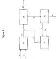
- FIG. 1a simplified process flow diagram of processes for upgrading resid not according to the invention is illustrated. Pumps, valves, heat exchangers, and other equipment are not shown for ease of illustration of embodiments disclosed herein.
- a resid and hydrogenmay be fed via flow lines 10 and 12, respectively, to a first hydrocracking reaction stage 14 containing a hydrocracking catalyst and operating at a temperature and pressure sufficient to convert at least a portion of the resid to lighter hydrocarbons.
- the first stage reactor effluentmay be recovered via flow line 16.
- the first stage effluentmay include reaction products and unreacted resid, which may include unreacted feed components such as asphaltenes, and hydrocracked asphaltenes having various boiling points, including those in the boiling range of the resid feedstock.
- a deasphalted oil fraction and hydrogenmay be fed via flow lines 18 and 20, respectively, to a second hydrocracking reaction stage 22 containing a hydrocracking catalyst and operating at a temperature and pressure to convert at least a portion of the deasphalted oil to lighter hydrocarbons.
- the second stage reactor effluentmay be recovered via flow line 24.
- the first stage effluent and the second stage effluent in flow lines 16, 24may then be fed to a separation system 26.
- the first and second stage eflfluentsmay be fractionated to recover at least one distillate hydrocarbon fraction and a hydrocarbon fraction including the unreacted resid, asphaltenes, and similar boiling range compounds formed from hydrocracking of the asphaltenes.
- the distillate hydrocarbon fractionsmay be recovered via one or more flow lines 28.
- the hydrocarbon fraction including the unreacted resid and asphaltenesmay be fed via flow line 30 to solvent deasphalting unit 32 to produce an asphaltenes fraction recovered via flow line 34 and a deasphalted oil fraction.
- the deasphalted oil fractionmay be recovered from solvent deasphalting unit 32 via flow line 18 and fed to second hydrocracking reaction stage 22, as described above.
- separation system 26may include a high pressure high temperature separator 40 (HP/HT separator) for separating the effluent liquid and vapor.
- HP/HT separatorhigh pressure high temperature separator 40
- the separated vapormay be recovered via flow line 42, and the separated liquid may be recovered via flow line 44
- the vapormay then be directed via flow line 42 to a gas cooling, purification, and recycle compression system 46.
- a hydrogen-containing gasmay be recovered from system 46 via flow line 48, a portion of which may be recycled to reactors 14, 16. Hydrocarbons condensed during the cooling and purification may be recovered via flow 50 and combined with the separated liquid in flow line 44 for further processing.
- the combined liquid stream 52may then be fed to an atmospheric distillation tower 54 to separate the stream into a fraction including hydrocarbons boiling in a range of atmospheric distillates and a first bottoms fraction including hydrocarbons having a normal boiling point of at least 340°C.
- the atmospheric distillatesmay be recovered via flow line 56, and the first bottoms fraction may be recovered via flow line 58.
- the first bottoms fractionmay then be fed to a vacuum distillation system 60 for separating the first bottoms fraction into a fraction including hydrocarbons boiling in a range of vacuum distllates and a second bottoms fraction including hydrocarbons having a normal boiling point of at least 480°C.
- the vacuum distillatesmay be recovered via flow line 62, and the second bottoms fraction may be recovered via flow line 30 and processed in the solvent deasphalting unit 32 as described above.
- the second bottoms fractionmay be cooled via indirect or direct heat exchange. Due to fouling of indirect heat exchange systems that often occurs with vacuum tower residues, direct heat exchange may be preferred, and may be performed, for example, by contacting the second bottoms fraction with at least one of a portion of the first bottoms fraction and a portion of the neat resid feed, such as may be fed via flow lines 64 and 66, respectively.
- processes disclosed hereinmay include a stand-alone gas cooling, purification and compression system 46.
- the vapor fraction recovered via flow line 42, or at least a portion thereofmay be processed in a common gas cooling, purification, and compression system, integrating the gas processing with other hydroprocessing units on site.
- asphaltenes recovered via flow line 34may be recycled to the first hycrocracking reactor stage in some embodiments. Upgrading or otherwise using asphaltenes recovered via flow line 34 may be performed using other various processes known to one skilled in the art.
- the asphaltenesmay be blended with a cutter such as FCC slurry oil and used as fuel oil, or processed alone or in combination with other feeds to delayed coking or gasification units, or pelletized to asphalt pellets.
- Figure 3(Comparative Example 1) is a process for upgrading resid, a standalone LC-FINING unit designed to produce stable low sulfur fuel oil, where the reactor data is based upon actual commercial plant performance data.
- Figure 4(Example 1) is a process for upgrading resid according to embodiments disclosed herein.
- the following description and comparative data, including key reaction parameters presented in Table 1,provides a comparison between the standalone process and an integrated process according to embodiments disclosed herein.
- a comparative system 300 for upgrading residis illustrated in Figure 3 , and includes a reaction section 302 and a separation system 304.
- Reaction section 302may include a single cracking reaction stage, such as an LC-FINING reaction system having three reactors in series. Resid and hydrogen are fed via flow lines 306 and 308, respectively, to reactor section 302 for cracking / upgrading of the resid. Effluent from reactor section 302 is then fed via flow line 310 to separation system 304 for fractionating the reactor effluent into desired fractions, including atmospheric distillates and vacuum distillates, recovered via flow lines 312 and 314, respectively, and a vacuum residue, recovered via flow line 316.
- separation system 304includes a high pressure high temperature separator 320, a gas cooling, purification, and compression system 322, an atmospheric fractionation tower 324, and a vacuum fractionation tower 326.
- Fresh or make-up hydrogenis fed to the gas cooling, purification, and compression system 322 via flow line 330, mixed with unreacted hydrogen and other light gases recovered in gas system 322, and forwarded to reactor section 302 via flow line 308.
- the total feed rate of resid (via flow line 306) to reactor section 302is approximately 3974 m 3 per stream day (25000 barrels per stream day (BPSD)).
- Reactor Section 302is operated at a temperature and pressure sufficient to react approximately 62% of the resid. Separation of the reactor effluent recovered via flow line 310 results in recovery of approximately 1311 m 3 per stream day (8250 BPSD) atmospheric distillates via flow line 312, 1211 m 3 per stream day (7620 BPSD) vacuum distillates via flow line 314, and 1599 m 3 per stream day (10060 BPSD) vacuum residue via flow line 316. An overall resid conversion of approximately 62% is achieved.
- a process for upgrading resid according to embodimentsis simulated with a flowsheet as illustrated in Figure 4 , which is similar to Figure 2 .
- reference numerals for Figure 2are used to represent the same components in Figure 4 , and the description of the process flow is not repeated here.
- the fresh / make-up hydrogenis fed via flow line 12 to the gas cooling, purification, and compression system 46.
- Reaction stage 14includes one reactor, and reaction stage 22 includes two reactors in series.
- the total feed rate of resid (via flow line 10) to first reactor stage 14is approximately 6359 m 3 per stream day (40000 BPSD).
- First reactor stage 14is operated at a temperature and pressure sufficient to react approximately 52% of the resid.
- Second reactor stage 22is operated at a temperature and pressure sufficient to react approximately 85% of the DAO feed.
- the vacuum residueis then processed in solvent deasphalting unit 32, operating at approximately 75% lift and recovery and feed via flow line 18 of approximately 2707 m 3 per stream day (17030 BPSD) DAO to second reaction stage 22.
- An overall resid conversion of approximately 84.3%is achieved.
- Example 1the overall residue conversion can be increased by more than 22% to 84.3% using processes according to embodiments disclosed herein (Example 1) as compared to a standalone LC-FINING unit (Comparative Example 1).
- Example 1The results of the Example 1 and Comparative Example 1 are further compared in Table 1.
- Table 1Comparative Example 1
- Example 1Example 1 Stage --- 1 2 Resid Conversion, 975+ vol % 62 52 85 Hydrodesulfurization achieved, wt. % 83 60 80 Total feed capacity, m 3 per stream day (BPSD) 3974 (25000) 6359 (40000) 2707 (17030) LHSV 1/hr.
- the conversion, reactor temperature, and reactor liquid hourly space velocity for the operation of the reactors in both Example 1 and Comparative Example 1are limited by the stability of the fuel oil, which typically must have a sediment content of less than 0.15 wt%, as measured by the Shell Hot Filtration Test (i.e. IP-375).
- Example 1The reaction system parameters for Example 1 are supported by data obtained from pilot plant testing of both the straight run vacuum residue and the DAO derived from the unconverted hydrocracked vacuum residue.
- the thermal operating severityi.e. reactor temperature and space velocity
- the thermal severity at which the DAO conversion stage can be operatedenables 60% more vacuum resid feed to be processed at 22% higher conversion while requiring only an 18% increase in reactor volume.
- atmospheric and vacuum distillate productionis increased from 64 vol% to 89 vol%, based on fresh vacuum resid feed.
- the unit catalyst addition ratei.e., lbs per barrel of vacuum resid feed
- the unit catalyst addition ratecan be reduced by 15% or more.
- light gas make and unit chemical hydrogen consumptionis reduced by 10 to 15% than would otherwise be the case if the same conversion were achieved without integration of a SDA Unit.
- embodiments disclosed hereinprovide for the efficient conversion of heavy hydrocarbons to lighter hydrocarbons via an integrated hydrocracking and solvent deasphalting process.
- processes according to embodiments disclosed hereinmay be useful for attaining a high overall feed conversion in a hydrocracking process, such as greater than 60%, 85%, or 95% conversion.
- processes according to embodiments disclosed hereinmay provide for reducing the required size of processing equipment, including at least one of a hydrocracking reactor and a solvent deasphalting unit. High conversions attained may result in relative recycle rates less than required by prior art processes to achieve high overall conversions. Additionally, hydrocracking at least a portion of the asphaltenes in the first reaction stage may provide for decreased feed rates, solvent usage, etc., associated with the solvent deasphalting unit as compared to prior art processes.
- processes according to embodiments disclosed hereinmay provide for decreased catalyst fouling rates, thereby extending catalyst cycle times and catalyst lifespan.
- operating conditions in the first reaction zonemay be selected to minimize sediment formation and catalyst fouling that may otherwise occur when hydrocracking asphaltenes.
- Removal of asphaltenes in between the reaction stagesmay additionally result in a lower sediment deposition problem in equipment associated with separation of liquid from vapor in the reactor effluent circuit, including equipment in the fractionation section.
Landscapes
- Chemical & Material Sciences (AREA)
- Oil, Petroleum & Natural Gas (AREA)
- Engineering & Computer Science (AREA)
- Chemical Kinetics & Catalysis (AREA)
- General Chemical & Material Sciences (AREA)
- Organic Chemistry (AREA)
- Production Of Liquid Hydrocarbon Mixture For Refining Petroleum (AREA)
- Catalysts (AREA)
- Other Liquid Machine Or Engine Such As Wave Power Use (AREA)
Description
- The invention relates to a process for hydrocracking and deasphalting resid.
- Hydrocarbon compounds are useful for a number of purposes. In particular, hydrocarbon compounds are useful, inter alia, as fuels, solvents, degreasers, cleaning agents, and polymer precursors. The most important source of hydrocarbon compounds is petroleum crude oil. Refining of crude oil into separate hydrocarbon compound fractions is a well-known processing technique.
- Crude oils range widely in their composition and physical and chemical properties. Heavy crudes are characterized by a relatively high viscosity, low API gravity, and high percentage of high boiling components (i.e., having a normal boiling point of greater than 510°C (950°F)).
- Refined petroleum products generally have higher average hydrogen to carbon ratios on a molecular basis. Therefore, the upgrading of a petroleum refinery hydrocarbon fraction is generally classified into one of two categories: hydrogen addition and carbon rejection. Hydrogen addition is performed by processes such as hydrocracking and hydrotreating. Carbon rejection processes typically produce a stream of rejected high carbon material which may be a liquid or a solid; e.g., coke deposits.
- Hydrocracking processes can be used to upgrade higher boiling materials, such as resid, typically present in heavy crude oil by converting them into more valuable lower boiling materials. For example, at least a portion of the resid feed to a hydrocracking reactor may be converted to a hydrocracking reaction product. The unreacted resid may be recovered from the hydrocracking process and either removed or recycled back to the hydrocracking reactor in order to increase the overall resid conversion.
- The resid conversion in a hydrocracking reactor can depend on a variety of factors, including feedstock composition; the type of reactor used; the reaction severity, including temperature and pressure conditions; reactor space velocity; and catalyst type and performance. In particular, the reaction severity may be used to increase the conversion. However, as the reaction severity increases, side reactions may occur inside the hydrocracking reactor to produce various byproducts in the form of coke precursors, sediments, other deposits as well as byproducts which form a secondary liquid phase. Excessive formation of such sediments can hinder subsequent processing and can deactivate the hydrocracking catalyst by poisoning, coking, or fouling. Deactivation of the hydrocracking catalyst can not only significantly reduce the resid conversion, but can also require more frequent change-outs of expensive catalyst. Formation of a secondary liquid phase not only deactivates the hydrocracking catalyst, but also limits the maximum conversion, thereby resulting in a higher catalyst consumption which can defluidize the catalyst. This leads to formation of "hot zones" within the catalyst bed, exacerbating the formation of coke, which further deactivates the hydrocracking catalyst.
- Sediment formation inside the hydrocracking reactor is also a strong function of the feedstock quality. For example, asphaltenes that may be present in the resid feed to the hydrocracking reactor system are especially prone to forming sediments when subjected to severe operating conditions. Thus, separation of the asphaltenes from the resid in order to increase the conversion may be desirable.
- One type of processes that may be used to remove such asphaltenes from the heavy hydrocarbon residue feed is solvent deasphalting. For example, solvent deasphalting typically involves physically separating the lighter hydrocarbons and the heavier hydrocarbons including asphaltenes based on their relative affinities for the solvent. A light solvent such as a C3 to C7 hydrocarbon can be used to dissolve or suspend the lighter hydrocarbons, commonly referred to as deasphalted oil, allowing the asphaltenes to be precipitated. The two phases are then separated and the solvent is recovered. Additional information on solvent deasphalting conditions, solvents and operations may be obtained from
U.S. Patent Nos. 4,239,616 ;4,440,633 ;4,354,922 ;4,354,928 ; and4,536,283 . - Several methods for integrating solvent deasphalting with hydrocracking in order to remove asphaltenes from resid are available. One such process is disclosed in
U.S. Patent Nos. 7,214,308 and7,279,090 . These patents disclose contacting the residue feed in a solvent deasphalting system to separate the asphaltenes from deasphalted oil. The deasphalted oil and the asphaltenes are then each reacted in separate hydrocracking reactor systems. - Moderate overall resid conversions (about 65% to 70% as described in
U.S. Patent No. 7,214,308 ) may be achieved using such processes, as both the deasphalted oil and the asphaltenes are separately hydrocracked. However, the hydrocracking of asphaltenes as disclosed is at high severity/high conversion, and may present special challenges, as discussed above. For example, operating the asphaltenes hydrocracker at high severity in order to increase the conversion may also cause a high rate of sediment formation, and a high rate of catalyst replacement. In contrast, operating the asphaltenes hydrocracker at low severity will suppress sediment formation, but the per-pass conversion of asphaltenes will be low. In order to achieve a higher overall resid conversion, such processes typically require a high recycle rate of the unreacted resid back to one or more of the hydrocracking reactors. Such high-volume recycle can significantly increase the size of the hydrocracking reactor and/or the upstream solvent deasphalting system.US 4 176 048 ,FR 2 906 813 EP 0 403 087 ,US 4 640 762 ,GB 1 560 148 WO 2008/014947 all disclose a process for upgrading resid. - Accordingly, there exists a need for improved resid hydrocracking processes that achieve a high resid conversion, reduce the overall equipment size of hydrocracking reactor and/or solvent deasphalter, and require less frequent hydrocracking catalyst change-outs.
- The process according to the invention is defined in claim 1.
- Other aspects and advantages will be apparent from the following description and the appended claims.
FIG. 1 is a simplified flow diagram of a hydrocracking and deasphalting process not according to the invention.FIG. 2 is a simplified flow diagram of a hydrocracking and deasphalting process according to embodiments disclosed herein.FIG. 3 is a simplified flow diagram of a process for upgrading resid for comparison to processes according to embodiments disclosed herein.FIG. 4 is a simplified flow diagram of a hydrocracking and deasphalting process according to embodiments disclosed herein.- Residuum hydrocarbon (resid) feedstocks useful in the invention disclosed herein may include various heavy crude and refinery fractions. For example, resid hydrocarbon feedstocks may include fresh resid hydrocarbon feeds, petroleum atmospheric or vacuum residue, hydrocracked atmospheric tower or vacuum tower bottoms, straight run vacuum gas oil, hydrocracked vacuum gas oil, fluid catalytically cracked (FCC) slurry oils or cycle oils, as well as other similar hydrocarbon streams, or a combination thereof, each of which may be straight run, process derived, hydrocracked, partially desulfurized, and/or low-metal streams. The above resid feedstocks may include various impurities, including asphaltenes, metals, organic sulfur, organic nitrogen, and Conradson carbon residue (CCR). The initial boiling point of the resid is typically greater than about 350°C.
- The process according to the invention disclosed herein for conversion of resid hydrocarbon feedstocks to lighter hydrocarbons include initially hydrocracking the resid feedstock, including any asphaltenes contained therein. The entire resid feed, including asphaltenes, may be reacted with hydrogen over a hydrocracking catalyst in a first hydrocracking reaction stage to convert at least a portion of the hydrocarbons to lighter molecules, including the conversion of at least a portion of the asphaltenes. In order to mitigate sediment formation, the first stage hydrocracking reaction may be conducted at temperatures and pressures that may avoid high rates of sediment formation and catalyst fouling (i.e., "moderate severity" reaction conditions). Resid conversion in the first reaction stage may be in the range from about 30 wt% to about 75 wt% in some embodiments.
- The reaction product from the first stage is separated to recover at least one distillate hydrocarbon fraction and a resid fraction including unreacted resid feed, asphaltenes, and any resid-boiling range products resulting from hydrocracking of the asphaltenes contained in the resid feedstock. Distillate hydrocarbon fractions recovered include hydrocarbons having a normal boiling temperature of less than about 340°C, and vacuum distillates, such as hydrocarbons having a normal boiling temperature of from about 468°C to about 579°C.
- The resid fraction is separated in a solvent deasphalting unit to recover a deasphalted oil fraction and an asphaltenes fraction. The solvent deasphalting unit may be, for example, as described in one or more of
U.S. Patent Nos. 4,239,616 ,4,440,633 ,4,354,922 ,4,354,928 ,4,536,283 , and7,214,308 . In the solvent deasphalting unit, a light hydrocarbon solvent may be used to selectively dissolve desired components of the resid fraction and reject the asphaltenes. In some embodiments, the light hydrocarbon solvent may be a C3 to C7 hydrocarbon, and may include propane, butane, isobutane, pentane, isopentane, hexane, heptane, and mixtures thereof. - The deasphalted oil fraction is reacted with hydrogen over a hydrocracking catalyst in a second hydrocracking reaction stage to convert at least a portion of the hydrocarbons to lighter molecules. The reaction product from the second hydrocracking reaction stage is separated along with the reaction product from the first hydrocracking stage to recover distillate range hydrocarbons produced in both the first and second hydrocracking reaction stages.
- The process of the invention disclosed herein thus include a solvent deasphalting unit downstream of the first hydrocracking reaction stage, providing for conversion of at least a portion of the asphaltenes to lighter, more valuable hydrocarbons. Hydrocracking of asphaltenes in the first reaction stage may provide for overall resid conversions that may be greater than about 60 wt% in some embodiments; greater than 85 wt% in other embodiments; and greater than 95 wt% in yet other embodiments. Additionally, due to conversion of at least a portion of the asphaltenes upstream, the required size for solvent deasphalting units used in embodiments may be less than would be required where the entire resid feed is initially processed.
- Catalysts used in the first and second reaction stages may be the same or different. Suitable hydrotreating and hydrocracking catalysts useful in the first and second reaction stages may include one or more elements selected from Groups 4-12 of the Periodic Table of the Elements. In some embodiments, the hydrotreating and hydrocracking catalysts according to embodiments disclosed herein may comprise, consist of, or consist essentially of one or more of nickel, cobalt, tungsten, molybdenum and combinations thereof, either unsupported or supported on a porous substrate such as silica, alumina, titania, or combinations thereof. As supplied from a manufacturer or as resulting from a regeneration process, the hydroconversion catalysts may be in the form of metal oxides, for example. If necessary or desired, the metal oxides may be converted to metal sulfides prior to or during use. In some embodiments, the hydrocracking catalysts may be pre-sulfided and / or pre-conditioned prior to introduction to the hydrocracking reactor.
- The first hydrotreating and hydrocracking reaction stage may include one or more reactors in series and/or parallel. Reactors suitable for use in the first hydrotreating and hydrocracking reaction stage may include any type of hydrocracking reactor. Ebullated bed reactors and fluidized bed reactors are preferred due to the processing of asphaltenes in the first reaction stage. In some embodiments, the first hydrocracking reaction stage includes only a single ebullated bed reactor.
- The second hydrocracking reaction stage may include one or more reactors in series and/or parallel. Reactors suitable for use in the second hydrocracking reaction stage may include any type of hydrocracking reactor, including ebullated bed reactors, fluidized bed reactors, and fixed bed reactors, among others. Asphaltenes may be present in the deasphalted oil only to a minor extent, thus a wide variety of reactor types may be used in the second reaction stage. For instance, a fixed bed reactor may be considered where the metals and Conradson carbon residue of the deasphalted oil fraction fed to the second hydrocracking reaction stage is less than 80 wppm and 10%, respectively. The number of reactors required may depend on the feed rate, the overall target resid conversion level, and the level of conversion attained in the first hydrocracking reaction stage.
- The fractionating of effluents from first and second reaction stages is achieved in a common fractionation system placed intermediate to the two hydrocracking reaction stages.
- The hydrocracking reaction in each of the first and second reaction stages may be conducted at a temperature in the range from about 360°C to about 480°C; from about 400°C to about 450°C in other embodiments. Pressures in each of the first and second reaction stages may be in the range from about 7 MPa (70 bara) to about 23 MPa (230 bara) in some embodiments; from about 10 to about 18 MPa (100 to about 180 bara) in other embodiments. The hydrocrackig reactions may also be conducted at a liquid hourly space velocity (LHSV) in the range from about 0.1 hr-1 to about 3.0 hr-1 in some embodiments; from about 0.2 hr-1 to about 2 hr-1 in other embodiments.
- In some embodiments, operating conditions in the first reaction stage may be less severe than those used in the second reaction stage, thus avoiding excessive catalyst replacement rates. Accordingly, overall catalyst replacement (i.e., for both stages combined) is also reduced. For example, the temperature in the first reaction stage may be less than the temperature in the second reaction stage. Operating conditions may be selected based upon the resid feedstock, including the content of impurities in the resid feedstock and the desired level of impurities to be removed in the first stage, among other factors. In some embodiments, resid conversion in the first reaction stage may be in the range from about 30 to about 60 wt%; from about 45 to about 55 wt% in other embodiments; and less than 50 wt% in yet other embodiments. In addition to hydrocracking the resid, sulfur and metal removal may each be in the range from about 40% to about 75%, and Conradson carbon removal may be in the range from about 30% to about 60%. In other embodiments, at least one of an operating temperature and an operating pressure in the first reaction stage may be greater than used in the second reaction stage.
- Although resid conversion in the first reaction stage may be purposefully reduced to prevent catalyst fouling, overall resid conversions for processes according to embodiments disclosed herein may be greater than 80% due to the partial conversion of asphaltenes in the first reaction stage and the conversion of DAO in the second reaction stage.. Using process flow schemes according to embodiments disclosed herein, overall resid conversions of at least 80%, 85%, 90% or higher may be attained, which is a significant improvement over what can be achieved with a two-stage hydrocracking system alone.
- Referring now to
Figure 1 , a simplified process flow diagram of processes for upgrading resid not according to the invention is illustrated. Pumps, valves, heat exchangers, and other equipment are not shown for ease of illustration of embodiments disclosed herein. - A resid and hydrogen may be fed via
flow lines hydrocracking reaction stage 14 containing a hydrocracking catalyst and operating at a temperature and pressure sufficient to convert at least a portion of the resid to lighter hydrocarbons. The first stage reactor effluent may be recovered viaflow line 16. As described above, the first stage effluent may include reaction products and unreacted resid, which may include unreacted feed components such as asphaltenes, and hydrocracked asphaltenes having various boiling points, including those in the boiling range of the resid feedstock. - A deasphalted oil fraction and hydrogen may be fed via
flow lines hydrocracking reaction stage 22 containing a hydrocracking catalyst and operating at a temperature and pressure to convert at least a portion of the deasphalted oil to lighter hydrocarbons. The second stage reactor effluent may be recovered viaflow line 24. - The first stage effluent and the second stage effluent in
flow lines separation system 26. Inseparation system 26, the first and second stage eflfluents may be fractionated to recover at least one distillate hydrocarbon fraction and a hydrocarbon fraction including the unreacted resid, asphaltenes, and similar boiling range compounds formed from hydrocracking of the asphaltenes. The distillate hydrocarbon fractions may be recovered via one ormore flow lines 28. - The hydrocarbon fraction including the unreacted resid and asphaltenes may be fed via
flow line 30 tosolvent deasphalting unit 32 to produce an asphaltenes fraction recovered viaflow line 34 and a deasphalted oil fraction. The deasphalted oil fraction may be recovered fromsolvent deasphalting unit 32 viaflow line 18 and fed to secondhydrocracking reaction stage 22, as described above. - Referring now to
Figure 2 , a simplified process flow diagram of processes for upgrading resid according to the invention is illustrated, where like numerals represent like parts. As described forFigure 1 , the first stage reactor effluent and the second stage reactor effluent may be fed viaflow lines separation system 26. In this embodiment,separation system 26 may include a high pressure high temperature separator 40 (HP/HT separator) for separating the effluent liquid and vapor. The separated vapor may be recovered viaflow line 42, and the separated liquid may be recovered viaflow line 44 - The vapor may then be directed via
flow line 42 to a gas cooling, purification, and recyclecompression system 46. A hydrogen-containing gas may be recovered fromsystem 46 viaflow line 48, a portion of which may be recycled toreactors flow 50 and combined with the separated liquid inflow line 44 for further processing. The combinedliquid stream 52 may then be fed to anatmospheric distillation tower 54 to separate the stream into a fraction including hydrocarbons boiling in a range of atmospheric distillates and a first bottoms fraction including hydrocarbons having a normal boiling point of at least 340°C. The atmospheric distillates may be recovered viaflow line 56, and the first bottoms fraction may be recovered viaflow line 58. - The first bottoms fraction may then be fed to a
vacuum distillation system 60 for separating the first bottoms fraction into a fraction including hydrocarbons boiling in a range of vacuum distllates and a second bottoms fraction including hydrocarbons having a normal boiling point of at least 480°C. The vacuum distillates may be recovered viaflow line 62, and the second bottoms fraction may be recovered viaflow line 30 and processed in thesolvent deasphalting unit 32 as described above. - It may be necessary to reduce the temperature of the second bottoms fraction prior to feeding the second bottoms fraction to
solvent deasphalting unit 32. The second bottoms fraction may be cooled via indirect or direct heat exchange. Due to fouling of indirect heat exchange systems that often occurs with vacuum tower residues, direct heat exchange may be preferred, and may be performed, for example, by contacting the second bottoms fraction with at least one of a portion of the first bottoms fraction and a portion of the neat resid feed, such as may be fed viaflow lines - As illustrated in
Figure 2 , processes disclosed herein may include a stand-alone gas cooling, purification andcompression system 46. In other embodiments, the vapor fraction recovered viaflow line 42, or at least a portion thereof, may be processed in a common gas cooling, purification, and compression system, integrating the gas processing with other hydroprocessing units on site. - Although not illustrated, at least a portion of the asphaltenes recovered via
flow line 34 may be recycled to the first hycrocracking reactor stage in some embodiments. Upgrading or otherwise using asphaltenes recovered viaflow line 34 may be performed using other various processes known to one skilled in the art. For example, the asphaltenes may be blended with a cutter such as FCC slurry oil and used as fuel oil, or processed alone or in combination with other feeds to delayed coking or gasification units, or pelletized to asphalt pellets. - The following examples are derived from modeling techniques. Although the work has been performed, the Inventors do not present these examples in the past tense to comply with applicable rules.
- In the examples presented below,
Figure 3 (Comparative Example 1) is a process for upgrading resid, a standalone LC-FINING unit designed to produce stable low sulfur fuel oil, where the reactor data is based upon actual commercial plant performance data.Figure 4 (Example 1) is a process for upgrading resid according to embodiments disclosed herein. The following description and comparative data, including key reaction parameters presented in Table 1, provides a comparison between the standalone process and an integrated process according to embodiments disclosed herein. - A
comparative system 300 for upgrading resid is illustrated inFigure 3 , and includes areaction section 302 and aseparation system 304.Reaction section 302, for example, may include a single cracking reaction stage, such as an LC-FINING reaction system having three reactors in series. Resid and hydrogen are fed viaflow lines reactor section 302 for cracking / upgrading of the resid. Effluent fromreactor section 302 is then fed viaflow line 310 toseparation system 304 for fractionating the reactor effluent into desired fractions, including atmospheric distillates and vacuum distillates, recovered viaflow lines flow line 316. - As illustrated in
Figure 3 ,separation system 304 includes a high pressurehigh temperature separator 320, a gas cooling, purification, andcompression system 322, anatmospheric fractionation tower 324, and avacuum fractionation tower 326. Fresh or make-up hydrogen is fed to the gas cooling, purification, andcompression system 322 viaflow line 330, mixed with unreacted hydrogen and other light gases recovered ingas system 322, and forwarded toreactor section 302 viaflow line 308. - The total feed rate of resid (via flow line 306) to
reactor section 302 is approximately 3974 m3 per stream day (25000 barrels per stream day (BPSD)).Reactor Section 302 is operated at a temperature and pressure sufficient to react approximately 62% of the resid. Separation of the reactor effluent recovered viaflow line 310 results in recovery of approximately 1311 m3 per stream day (8250 BPSD) atmospheric distillates viaflow line 312, 1211 m3 per stream day (7620 BPSD) vacuum distillates viaflow line 314, and 1599 m3 per stream day (10060 BPSD) vacuum residue viaflow line 316. An overall resid conversion of approximately 62% is achieved. - A process for upgrading resid according to embodiments is simulated with a flowsheet as illustrated in
Figure 4 , which is similar toFigure 2 . As such, reference numerals forFigure 2 are used to represent the same components inFigure 4 , and the description of the process flow is not repeated here. As withFigure 3 , the fresh / make-up hydrogen is fed viaflow line 12 to the gas cooling, purification, andcompression system 46.Reaction stage 14 includes one reactor, andreaction stage 22 includes two reactors in series. - The total feed rate of resid (via flow line 10) to
first reactor stage 14 is approximately 6359 m3 per stream day (40000 BPSD).First reactor stage 14 is operated at a temperature and pressure sufficient to react approximately 52% of the resid.Second reactor stage 22 is operated at a temperature and pressure sufficient to react approximately 85% of the DAO feed. Combined separation of the first and second stage effluents recovered viaflow lines flow line 56, 2821 m3 per stream day (17745 BPSD) vacuum distillates recovered viaflow line 62, and 3609 m3 per stream day (22705 BPSD) vacuum residue recovered viaflow line 34. The vacuum residue is then processed insolvent deasphalting unit 32, operating at approximately 75% lift and recovery and feed viaflow line 18 of approximately 2707 m3 per stream day (17030 BPSD) DAO tosecond reaction stage 22. An overall resid conversion of approximately 84.3% is achieved. - As shown by the examples above, the overall residue conversion can be increased by more than 22% to 84.3% using processes according to embodiments disclosed herein (Example 1) as compared to a standalone LC-FINING unit (Comparative Example 1). The results of the Example 1 and Comparative Example 1 are further compared in Table 1.
Table 1. Comparative Example 1 Example 1 Example 1 Stage --- 1 2 Resid Conversion, 975+ vol % 62 52 85 Hydrodesulfurization achieved, wt. % 83 60 80 Total feed capacity, m3 per stream day (BPSD) 3974 (25000) 6359 (40000) 2707 (17030) LHSV 1/hr. X 2.2X 1.5X Number of Reactors 3 1 2 Reactor Operating Temp, °C Y Y+15 Y+23 Chemical Hydrogen Consumption, SCFH Z 1.25Z 0.82Z Total Reactor Volume, m3 A 0.72A 0.45A Catalyst Addition Rate, g/m3 (lbs/Bbl) B 0.75B 0.25B - The conversion, reactor temperature, and reactor liquid hourly space velocity for the operation of the reactors in both Example 1 and Comparative Example 1 are limited by the stability of the fuel oil, which typically must have a sediment content of less than 0.15 wt%, as measured by the Shell Hot Filtration Test (i.e. IP-375).
- The reaction system parameters for Example 1 are supported by data obtained from pilot plant testing of both the straight run vacuum residue and the DAO derived from the unconverted hydrocracked vacuum residue. As a result of the reduced residue conversion from
first stage reactor 14, the thermal operating severity (i.e. reactor temperature and space velocity) can be increased, compared with the reactors in Comparative Example 1, producing stable low sulfur fuel oil and without significantly affecting the sediment formation. This, in combination with the higher thermal severity at which the DAO conversion stage can be operated, enables 60% more vacuum resid feed to be processed at 22% higher conversion while requiring only an 18% increase in reactor volume. As a result of the higher conversion attainable with the flow scheme of Example 1, atmospheric and vacuum distillate production is increased from 64 vol% to 89 vol%, based on fresh vacuum resid feed. - In addition due to the reduced metals removal in the first reaction stage and the rejection of metals in the SDA pitch (asphalt recovered via stream 34) the unit catalyst addition rate (i.e., lbs per barrel of vacuum resid feed) can be reduced by 15% or more. Similarly, as a result of the reduced CCR and asphaltene conversion in the first reaction stage and the subsequent rejection of asphaltenes in the SDA pitch, light gas make and unit chemical hydrogen consumption is reduced by 10 to 15% than would otherwise be the case if the same conversion were achieved without integration of a SDA Unit.
- As described above, embodiments disclosed herein provide for the efficient conversion of heavy hydrocarbons to lighter hydrocarbons via an integrated hydrocracking and solvent deasphalting process.
- In one aspect, processes according to embodiments disclosed herein may be useful for attaining a high overall feed conversion in a hydrocracking process, such as greater than 60%, 85%, or 95% conversion.
- In another aspect, processes according to embodiments disclosed herein may provide for reducing the required size of processing equipment, including at least one of a hydrocracking reactor and a solvent deasphalting unit. High conversions attained may result in relative recycle rates less than required by prior art processes to achieve high overall conversions. Additionally, hydrocracking at least a portion of the asphaltenes in the first reaction stage may provide for decreased feed rates, solvent usage, etc., associated with the solvent deasphalting unit as compared to prior art processes.
- In yet another aspect, processes according to embodiments disclosed herein may provide for decreased catalyst fouling rates, thereby extending catalyst cycle times and catalyst lifespan. For example, operating conditions in the first reaction zone may be selected to minimize sediment formation and catalyst fouling that may otherwise occur when hydrocracking asphaltenes.
- Significant reductions in capital and operating costs may be realized due to one or more of the low recycle requirements, efficient catalyst usage, and partial conversion of asphaltenes prior to solvent deasphalting.
- Removal of asphaltenes in between the reaction stages may additionally result in a lower sediment deposition problem in equipment associated with separation of liquid from vapor in the reactor effluent circuit, including equipment in the fractionation section.
Claims (15)
- A process for upgrading resid, comprising:hydrocracking a resid in a first reaction stage (14) to form a first stage effluent;hydrocracking a deasphalted oil fraction in a second reaction stage (22) to form a second stage effluent;feeding the first stage effluent and the second stage effluent to a separation system (26);fractionating the first stage effluent and the second stage effluent in the separation system (26) to recover at least one distillate hydrocarbon fraction and a resid hydrocarbon fraction; andfeeding the resid hydrocarbon fraction to a solvent deasphalting unit (32) to provide an asphaltene fraction and the deasphalted oil fraction,wherein hydrocracking a resid comprises:feeding hydrogen and the resid to a first reactor containing a first hydrocracking catalyst;contacting the resid and hydrogen in the presence of the first hydrocracking catalyst at conditions of temperature and pressure to crack at least a portion of the resid;recovering the first stage effluent from the first reactor;wherein hydrocracking a deasphalted oil fraction comprises:feeding hydrogen and the deasphalted oil fraction to a second reactor containing a second hydrocracking catalyst;contacting the deasphalted oil fraction and hydrogen in the presence of the second hydrocracking catalyst at conditions of temperature and pressure to crack at least a portion of the deasphalted oil; andrecovering the second stage effluent from the second reactor, andwherein the fractionating comprises:separating the first and second stage effluents in a high pressure high temperature separator (40) to provide a gas phase product and a liquid phase product;separating the liquid phase product in an atmospheric distillation tower (54) to recover a fraction comprising hydrocarbons boiling in a range of atmospheric distillates and a first bottoms fraction comprising hydrocarbons having a normal boiling point of at least 340°C;separating the bottoms fraction in a vacuum distillation tower (60) to recover a fraction comprising hydrocarbons boiling in a range of vacuum distillates and a second bottoms fraction comprising hydrocarbons having a boiling temperature of at least 480°C; andfeeding the second bottoms fraction to the solvent deasphalting unit (32) as the resid hydrocarbon fraction.
- The process of claim 1, wherein at least one of an operating temperature and an operating pressure in the second reaction stage (22) is greater than an operating temperature and an operating pressure of the first reaction stage (14).
- The process of claim 1, wherein at least a portion of asphaltenes in the resid are hydrocracked in the first reaction stage (14).
- The process of claim 1, further comprising operating the first reaction stage (14) at a temperature and pressure to hydrocrack the resid at a conversion from about 30 wt.% to about 75 wt.% of the resid.
- The process of claim 1, further comprising operating the first reaction stage (14) at a temperature and pressure to hydrocrack the resid at an overall resid conversion of at least 60 wt.%.
- The process of claim 5, wherein the overall resid conversion is of at least 95 wt.%.
- The process of claim 1, wherein the resid hydrocarbon fraction comprises hydrocarbons with a normal boiling point of at least 340°C.
- The process of claim 1, wherein the first reaction stage (14) comprises a single ebullated bed reactor.
- The process of claim 1, wherein the second reaction stage (22) comprises at least one of an ebullated bed reactor and a fixed bed reactor.
- The process of claim 1, further comprising
cooling the gas phase product to recover a hydrogen-containing gas fraction and a distillate fraction; and
feeding the distillate fraction to the separating the liquid phase product. - The process of claim 10, further comprising recycling at least a portion of the recovered hydrogen to at least one of the first reactor and the second reactor.
- The process of claim 1, further comprising cooling the second bottoms fraction via direct heat exchange with at least one of a portion of the resid and a portion of the first bottoms fraction.
- The process of claim 1, wherein at least one of an operating temperature and an operating pressure in the second reactor is less than an operating temperature and an operating pressure of the first reactor.
- The process of claim 1, wherein the resid hydrocarbon fraction comprises hydrocarbons with a normal boiling point of at least 480°C.
- The process of claim 1, wherein the fractionating comprises feeding the first stage effluent and the second stage effluent to a common fractionation system.
Priority Applications (4)
| Application Number | Priority Date | Filing Date | Title |
|---|---|---|---|
| PL10726674TPL2445993T3 (en) | 2009-06-23 | 2010-06-16 | Multistage resid hydrocracking |
| HRP20191157TTHRP20191157T1 (en) | 2009-06-23 | 2010-06-16 | MULTI-STAGE HYDROCRAKING OF THE RESIDUE |
| EP12181854.6AEP2562235B1 (en) | 2009-06-23 | 2010-06-16 | Multistage resid hydrocracking |
| PL12181854TPL2562235T3 (en) | 2009-06-23 | 2010-06-16 | Multistage resid hydrocracking |
Applications Claiming Priority (2)
| Application Number | Priority Date | Filing Date | Title |
|---|---|---|---|
| US12/490,089US8287720B2 (en) | 2009-06-23 | 2009-06-23 | Multistage resid hydrocracking |
| PCT/US2010/001736WO2010151300A1 (en) | 2009-06-23 | 2010-06-16 | Multistage resid hydrocracking |
Related Child Applications (2)
| Application Number | Title | Priority Date | Filing Date |
|---|---|---|---|
| EP12181854.6ADivision-IntoEP2562235B1 (en) | 2009-06-23 | 2010-06-16 | Multistage resid hydrocracking |
| EP12181854.6ADivisionEP2562235B1 (en) | 2009-06-23 | 2010-06-16 | Multistage resid hydrocracking |
Publications (2)
| Publication Number | Publication Date |
|---|---|
| EP2445993A1 EP2445993A1 (en) | 2012-05-02 |
| EP2445993B1true EP2445993B1 (en) | 2019-03-27 |
Family
ID=42727438
Family Applications (2)
| Application Number | Title | Priority Date | Filing Date |
|---|---|---|---|
| EP10726674.4AActiveEP2445993B1 (en) | 2009-06-23 | 2010-06-16 | Multistage resid hydrocracking |
| EP12181854.6AActiveEP2562235B1 (en) | 2009-06-23 | 2010-06-16 | Multistage resid hydrocracking |
Family Applications After (1)
| Application Number | Title | Priority Date | Filing Date |
|---|---|---|---|
| EP12181854.6AActiveEP2562235B1 (en) | 2009-06-23 | 2010-06-16 | Multistage resid hydrocracking |
Country Status (17)
| Country | Link |
|---|---|
| US (3) | US8287720B2 (en) |
| EP (2) | EP2445993B1 (en) |
| KR (2) | KR101351147B1 (en) |
| CN (2) | CN102803441B (en) |
| BR (1) | BRPI1015117B1 (en) |
| CA (1) | CA2764971C (en) |
| EC (1) | ECSP12011619A (en) |
| ES (2) | ES2856200T3 (en) |
| HR (2) | HRP20191157T1 (en) |
| HU (2) | HUE044287T2 (en) |
| MX (1) | MX2011013604A (en) |
| MY (3) | MY194683A (en) |
| PL (2) | PL2562235T3 (en) |
| PT (2) | PT2445993T (en) |
| RU (2) | RU2538961C1 (en) |
| SG (1) | SG177364A1 (en) |
| WO (1) | WO2010151300A1 (en) |
Families Citing this family (25)
| Publication number | Priority date | Publication date | Assignee | Title |
|---|---|---|---|---|
| US8287720B2 (en) | 2009-06-23 | 2012-10-16 | Lummus Technology Inc. | Multistage resid hydrocracking |
| US10400184B2 (en)* | 2011-08-31 | 2019-09-03 | Exxonmobil Research And Engineering Company | Hydroprocessing of heavy hydrocarbon feeds using small pore catalysts |
| US9028674B2 (en) | 2013-01-17 | 2015-05-12 | Lummus Technology Inc. | Conversion of asphaltenic pitch within an ebullated bed residuum hydrocracking process |
| US20140221713A1 (en)* | 2013-02-04 | 2014-08-07 | Lummus Technology Inc. | Residue hydrocracking processing |
| US20140221709A1 (en)* | 2013-02-04 | 2014-08-07 | Lummus Technology Inc. | Integration of residue hydrocracking and solvent deasphalting |
| US9650312B2 (en) | 2013-03-14 | 2017-05-16 | Lummus Technology Inc. | Integration of residue hydrocracking and hydrotreating |
| US10208261B2 (en) | 2014-02-12 | 2019-02-19 | Lummus Technology Inc. | Processing vacuum residuum and vacuum gas oil in ebullated bed reactor systems |
| RU2546677C1 (en)* | 2014-03-27 | 2015-04-10 | Игорь Анатольевич Мнушкин | Method and installation of hydrocracking with obtaining motor fuels |
| US9783748B2 (en)* | 2014-09-09 | 2017-10-10 | Uop Llc | Process for producing diesel fuel |
| US9663732B2 (en) | 2014-09-09 | 2017-05-30 | Uop Llc | Process for controlling operations of a residue process unit |
| CA2963546C (en) | 2014-10-07 | 2022-11-01 | Shell Internationale Research Maatschappij B.V. | A hydrocracking process integrated with solvent deasphalting to reduce heavy polycyclic aromatic buildup in heavy oil hydrocracker recycle stream |
| PL3209753T3 (en) | 2014-10-22 | 2025-09-08 | Shell Internationale Research Maatschappij B.V. | Hydrocracking process integrated with vacuum distillation and solvent dewaxing to reduce the accumulation of heavy polycyclic aromatic compounds |
| US9695369B2 (en) | 2014-11-21 | 2017-07-04 | Lummus Technology Inc. | Process to upgrade partially converted vacuum residua |
| US10144884B2 (en) | 2015-06-18 | 2018-12-04 | Uop Llc | Two stage hydrocracking process and apparatus |
| US11015132B2 (en)* | 2016-08-18 | 2021-05-25 | Haldor Topsøe A/S | High conversion hydrocracking process |
| EP3559171B1 (en)* | 2016-12-22 | 2025-05-14 | Lummus Technology LLC | Multistage resid hydrocracking |
| US11788017B2 (en) | 2017-02-12 | 2023-10-17 | Magëmã Technology LLC | Multi-stage process and device for reducing environmental contaminants in heavy marine fuel oil |
| US10604709B2 (en) | 2017-02-12 | 2020-03-31 | Magēmā Technology LLC | Multi-stage device and process for production of a low sulfur heavy marine fuel oil from distressed heavy fuel oil materials |
| US12281266B2 (en) | 2017-02-12 | 2025-04-22 | Magẽmã Technology LLC | Heavy marine fuel oil composition |
| US12071592B2 (en) | 2017-02-12 | 2024-08-27 | Magēmā Technology LLC | Multi-stage process and device utilizing structured catalyst beds and reactive distillation for the production of a low sulfur heavy marine fuel oil |
| US12025435B2 (en) | 2017-02-12 | 2024-07-02 | Magēmã Technology LLC | Multi-stage device and process for production of a low sulfur heavy marine fuel oil |
| US20190233741A1 (en) | 2017-02-12 | 2019-08-01 | Magēmā Technology, LLC | Multi-Stage Process and Device for Reducing Environmental Contaminates in Heavy Marine Fuel Oil |
| FR3075809B1 (en) | 2017-12-21 | 2020-09-11 | Ifp Energies Now | PROCESS FOR CONVERTING HEAVY LOADS OF HYDROCARBONS WITH RECYCLE OF A DESASPHALTED OIL |
| US11261387B2 (en) | 2019-07-23 | 2022-03-01 | Saudi Arabian Oil Company | Fuel oil conversion |
| FR3113062B1 (en)* | 2020-07-30 | 2023-11-03 | Ifp Energies Now | Residue hydroconversion process with several hydroconversion stages integrating a deasphalting step |
Family Cites Families (24)
| Publication number | Priority date | Publication date | Assignee | Title |
|---|---|---|---|---|
| NL7510465A (en)* | 1975-09-05 | 1977-03-08 | Shell Int Research | PROCESS FOR CONVERTING HYDROCARBONS. |
| NL7612960A (en) | 1976-11-22 | 1978-05-24 | Shell Int Research | METHOD FOR CONVERTING HYDROCARBONS. |
| US4176048A (en)* | 1978-10-31 | 1979-11-27 | Standard Oil Company (Indiana) | Process for conversion of heavy hydrocarbons |
| US4239616A (en)* | 1979-07-23 | 1980-12-16 | Kerr-Mcgee Refining Corporation | Solvent deasphalting |
| US4354928A (en)* | 1980-06-09 | 1982-10-19 | Mobil Oil Corporation | Supercritical selective extraction of hydrocarbons from asphaltic petroleum oils |
| US4354922A (en)* | 1981-03-31 | 1982-10-19 | Mobil Oil Corporation | Processing of heavy hydrocarbon oils |
| FR2504934A1 (en)* | 1981-04-30 | 1982-11-05 | Inst Francais Du Petrole | IMPROVED METHOD FOR SOLVENT DESASPHALTING OF HEAVY FRACTIONS OF HYDROCARBONS |
| US4536283A (en)* | 1984-08-20 | 1985-08-20 | Exxon Research And Engineering Co. | Integrated process for deasphalting heavy oils using a gaseous antisolvent |
| CA1222471A (en)* | 1985-06-28 | 1987-06-02 | H. John Woods | Process for improving the yield of distillables in hydrogen donor diluent cracking |
| GB8828335D0 (en)* | 1988-12-05 | 1989-01-05 | Shell Int Research | Process for conversion of heavy hydrocarbonaceous feedstock |
| CA2010774A1 (en) | 1989-06-12 | 1990-12-12 | William L. Lafferty, Jr. | Conversion increase of vacuum residiums |
| MX9502237A (en)* | 1994-05-19 | 1997-02-28 | Shell Int Research | Process for conversion of a hydrocarbon residual oil. |
| FR2753982B1 (en) | 1996-10-02 | 1999-05-28 | Inst Francais Du Petrole | MULTI-STAGE CATALYTIC PROCESS FOR CONVERTING A HEAVY HYDROCARBON FRACTION |
| US6514403B1 (en)* | 2000-04-20 | 2003-02-04 | Abb Lummus Global Inc. | Hydrocracking of vacuum gas and other oils using a cocurrent/countercurrent reaction system and a post-treatment reactive distillation system |
| US6436279B1 (en)* | 2000-11-08 | 2002-08-20 | Axens North America, Inc. | Simplified ebullated-bed process with enhanced reactor kinetics |
| US7214308B2 (en)* | 2003-02-21 | 2007-05-08 | Institut Francais Du Petrole | Effective integration of solvent deasphalting and ebullated-bed processing |
| US7279090B2 (en)* | 2004-12-06 | 2007-10-09 | Institut Francais Du Pe'trole | Integrated SDA and ebullated-bed process |
| ITMI20042445A1 (en)* | 2004-12-22 | 2005-03-22 | Eni Spa | PROCEDURE FOR THE CONVERSION OF HEAVY CHARGES WHICH WEIGHING AND DISTILLATION WASTE |
| US7594990B2 (en)* | 2005-11-14 | 2009-09-29 | The Boc Group, Inc. | Hydrogen donor solvent production and use in resid hydrocracking processes |
| CN100366709C (en)* | 2006-04-17 | 2008-02-06 | 中国石油化工集团公司 | Combined process for processing heavy oil |
| CN100569925C (en)* | 2006-06-16 | 2009-12-16 | 中国石油化工股份有限公司 | A combined processing method for heavy and residual oil |
| ITMI20061512A1 (en) | 2006-07-31 | 2008-02-01 | Eni Spa | PROCEDURE FOR THE TOTAL CONVERSION OF HEAVY DUTIES TO DISTILLATES |
| FR2906813A1 (en) | 2006-10-06 | 2008-04-11 | Inst Francais Du Petrole | Heavy petroleum feed e.g. vacuum residue, hydroconverting method for producing petrol, involves de-asphalting vacuum residue to obtain de-asphalted oil, and recycling totality of oil by hydroconversion |
| US8287720B2 (en) | 2009-06-23 | 2012-10-16 | Lummus Technology Inc. | Multistage resid hydrocracking |
- 2009
- 2009-06-23USUS12/490,089patent/US8287720B2/enactiveActive
- 2010
- 2010-06-16CNCN201080027522.0Apatent/CN102803441B/enactiveActive
- 2010-06-16CACA2764971Apatent/CA2764971C/enactiveActive
- 2010-06-16PLPL12181854Tpatent/PL2562235T3/enunknown
- 2010-06-16HRHRP20191157TTpatent/HRP20191157T1/enunknown
- 2010-06-16KRKR1020127001729Apatent/KR101351147B1/enactiveActive
- 2010-06-16MYMYPI2018000279Apatent/MY194683A/enunknown
- 2010-06-16MXMX2011013604Apatent/MX2011013604A/enactiveIP Right Grant
- 2010-06-16HUHUE10726674patent/HUE044287T2/enunknown
- 2010-06-16CNCN201610232031.9Apatent/CN105838416B/enactiveActive
- 2010-06-16MYMYPI2011006267Apatent/MY159468A/enunknown
- 2010-06-16BRBRPI1015117-6Apatent/BRPI1015117B1/enactiveIP Right Grant
- 2010-06-16ESES12181854Tpatent/ES2856200T3/enactiveActive
- 2010-06-16PTPT10726674Tpatent/PT2445993T/enunknown
- 2010-06-16SGSG2011096229Apatent/SG177364A1/enunknown
- 2010-06-16WOPCT/US2010/001736patent/WO2010151300A1/enactiveApplication Filing
- 2010-06-16EPEP10726674.4Apatent/EP2445993B1/enactiveActive
- 2010-06-16PLPL10726674Tpatent/PL2445993T3/enunknown
- 2010-06-16ESES10726674Tpatent/ES2732813T3/enactiveActive
- 2010-06-16MYMYPI2014002911Apatent/MY169463A/enunknown
- 2010-06-16RURU2013131001/04Apatent/RU2538961C1/enactive
- 2010-06-16KRKR1020137023787Apatent/KR101696017B1/enactiveActive
- 2010-06-16HUHUE12181854Apatent/HUE053691T2/enunknown
- 2010-06-16PTPT121818546Tpatent/PT2562235T/enunknown
- 2010-06-16RURU2012102048/04Apatent/RU2495911C2/enactive
- 2010-06-16EPEP12181854.6Apatent/EP2562235B1/enactiveActive
- 2012
- 2012-01-23ECEC2012011619Apatent/ECSP12011619A/enunknown
- 2012-06-07USUS13/491,147patent/US9441174B2/enactiveActive
- 2016
- 2016-08-05USUS15/229,530patent/US9873839B2/enactiveActive
- 2021
- 2021-03-26HRHRP20210490TTpatent/HRP20210490T1/enunknown
Non-Patent Citations (1)
| Title |
|---|
| None* |
Also Published As
Similar Documents
| Publication | Publication Date | Title |
|---|---|---|
| US9873839B2 (en) | Multistage resid hydrocracking | |
| KR102327288B1 (en) | Multistage resid hydrocracking | |
| EP3221430B1 (en) | Process and system to upgrade partially converted vacuum residua | |
| US7938952B2 (en) | Process for multistage residue hydroconversion integrated with straight-run and conversion gasoils hydroconversion steps | |
| CN114058404A (en) | Process for Hydrogenation of Conversion Residue with Several Hydroconversion Stages Incorporating a Deasphalting Step |
Legal Events
| Date | Code | Title | Description |
|---|---|---|---|
| PUAI | Public reference made under article 153(3) epc to a published international application that has entered the european phase | Free format text:ORIGINAL CODE: 0009012 | |
| 17P | Request for examination filed | Effective date:20120117 | |
| AK | Designated contracting states | Kind code of ref document:A1 Designated state(s):AL AT BE BG CH CY CZ DE DK EE ES FI FR GB GR HR HU IE IS IT LI LT LU LV MC MK MT NL NO PL PT RO SE SI SK SM TR | |
| DAX | Request for extension of the european patent (deleted) | ||
| 17Q | First examination report despatched | Effective date:20150929 | |
| STAA | Information on the status of an ep patent application or granted ep patent | Free format text:STATUS: EXAMINATION IS IN PROGRESS | |
| GRAP | Despatch of communication of intention to grant a patent | Free format text:ORIGINAL CODE: EPIDOSNIGR1 | |
| STAA | Information on the status of an ep patent application or granted ep patent | Free format text:STATUS: GRANT OF PATENT IS INTENDED | |
| RIC1 | Information provided on ipc code assigned before grant | Ipc:C10G 67/04 20060101ALI20181016BHEP Ipc:C10G 67/00 20060101ALI20181016BHEP Ipc:C10G 47/00 20060101ALI20181016BHEP Ipc:C10G 21/00 20060101AFI20181016BHEP | |
| INTG | Intention to grant announced | Effective date:20181031 | |
| GRAS | Grant fee paid | Free format text:ORIGINAL CODE: EPIDOSNIGR3 | |
| GRAA | (expected) grant | Free format text:ORIGINAL CODE: 0009210 | |
| STAA | Information on the status of an ep patent application or granted ep patent | Free format text:STATUS: THE PATENT HAS BEEN GRANTED | |
| RAP1 | Party data changed (applicant data changed or rights of an application transferred) | Owner name:LUMMUS TECHNOLOGY LLC | |
| AK | Designated contracting states | Kind code of ref document:B1 Designated state(s):AL AT BE BG CH CY CZ DE DK EE ES FI FR GB GR HR HU IE IS IT LI LT LU LV MC MK MT NL NO PL PT RO SE SI SK SM TR | |
| REG | Reference to a national code | Ref country code:GB Ref legal event code:FG4D | |
| REG | Reference to a national code | Ref country code:CH Ref legal event code:EP | |
| REG | Reference to a national code | Ref country code:AT Ref legal event code:REF Ref document number:1113058 Country of ref document:AT Kind code of ref document:T Effective date:20190415 | |
| REG | Reference to a national code | Ref country code:IE Ref legal event code:FG4D | |
| REG | Reference to a national code | Ref country code:DE Ref legal event code:R096 Ref document number:602010057821 Country of ref document:DE | |
| REG | Reference to a national code | Ref country code:HR Ref legal event code:TUEP Ref document number:P20191157 Country of ref document:HR | |
| REG | Reference to a national code | Ref country code:PT Ref legal event code:SC4A Ref document number:2445993 Country of ref document:PT Date of ref document:20190710 Kind code of ref document:T Free format text:AVAILABILITY OF NATIONAL TRANSLATION Effective date:20190627 | |
| REG | Reference to a national code | Ref country code:NL Ref legal event code:FP | |
| REG | Reference to a national code | Ref country code:SE Ref legal event code:TRGR | |
| PG25 | Lapsed in a contracting state [announced via postgrant information from national office to epo] | Ref country code:LT Free format text:LAPSE BECAUSE OF FAILURE TO SUBMIT A TRANSLATION OF THE DESCRIPTION OR TO PAY THE FEE WITHIN THE PRESCRIBED TIME-LIMIT Effective date:20190327 Ref country code:NO Free format text:LAPSE BECAUSE OF FAILURE TO SUBMIT A TRANSLATION OF THE DESCRIPTION OR TO PAY THE FEE WITHIN THE PRESCRIBED TIME-LIMIT Effective date:20190627 | |
| PG25 | Lapsed in a contracting state [announced via postgrant information from national office to epo] | Ref country code:GR Free format text:LAPSE BECAUSE OF FAILURE TO SUBMIT A TRANSLATION OF THE DESCRIPTION OR TO PAY THE FEE WITHIN THE PRESCRIBED TIME-LIMIT Effective date:20190628 Ref country code:LV Free format text:LAPSE BECAUSE OF FAILURE TO SUBMIT A TRANSLATION OF THE DESCRIPTION OR TO PAY THE FEE WITHIN THE PRESCRIBED TIME-LIMIT Effective date:20190327 | |
| REG | Reference to a national code | Ref country code:AT Ref legal event code:MK05 Ref document number:1113058 Country of ref document:AT Kind code of ref document:T Effective date:20190327 | |
| REG | Reference to a national code | Ref country code:HR Ref legal event code:ODRP Ref document number:P20191157 Country of ref document:HR Payment date:20190710 Year of fee payment:10 | |
| REG | Reference to a national code | Ref country code:SK Ref legal event code:T3 Ref document number:E 31494 Country of ref document:SK | |
| REG | Reference to a national code | Ref country code:HR Ref legal event code:T1PR Ref document number:P20191157 Country of ref document:HR | |
| REG | Reference to a national code | Ref country code:HU Ref legal event code:AG4A Ref document number:E044287 Country of ref document:HU | |
| PG25 | Lapsed in a contracting state [announced via postgrant information from national office to epo] | Ref country code:RO Free format text:LAPSE BECAUSE OF FAILURE TO SUBMIT A TRANSLATION OF THE DESCRIPTION OR TO PAY THE FEE WITHIN THE PRESCRIBED TIME-LIMIT Effective date:20190327 Ref country code:CZ Free format text:LAPSE BECAUSE OF FAILURE TO SUBMIT A TRANSLATION OF THE DESCRIPTION OR TO PAY THE FEE WITHIN THE PRESCRIBED TIME-LIMIT Effective date:20190327 Ref country code:AL Free format text:LAPSE BECAUSE OF FAILURE TO SUBMIT A TRANSLATION OF THE DESCRIPTION OR TO PAY THE FEE WITHIN THE PRESCRIBED TIME-LIMIT Effective date:20190327 Ref country code:EE Free format text:LAPSE BECAUSE OF FAILURE TO SUBMIT A TRANSLATION OF THE DESCRIPTION OR TO PAY THE FEE WITHIN THE PRESCRIBED TIME-LIMIT Effective date:20190327 | |
| REG | Reference to a national code | Ref country code:ES Ref legal event code:FG2A Ref document number:2732813 Country of ref document:ES Kind code of ref document:T3 Effective date:20191126 | |
| PG25 | Lapsed in a contracting state [announced via postgrant information from national office to epo] | Ref country code:SM Free format text:LAPSE BECAUSE OF FAILURE TO SUBMIT A TRANSLATION OF THE DESCRIPTION OR TO PAY THE FEE WITHIN THE PRESCRIBED TIME-LIMIT Effective date:20190327 | |
| PG25 | Lapsed in a contracting state [announced via postgrant information from national office to epo] | Ref country code:IS Free format text:LAPSE BECAUSE OF FAILURE TO SUBMIT A TRANSLATION OF THE DESCRIPTION OR TO PAY THE FEE WITHIN THE PRESCRIBED TIME-LIMIT Effective date:20190727 Ref country code:AT Free format text:LAPSE BECAUSE OF FAILURE TO SUBMIT A TRANSLATION OF THE DESCRIPTION OR TO PAY THE FEE WITHIN THE PRESCRIBED TIME-LIMIT Effective date:20190327 | |
| REG | Reference to a national code | Ref country code:DE Ref legal event code:R119 Ref document number:602010057821 Country of ref document:DE | |
| PG25 | Lapsed in a contracting state [announced via postgrant information from national office to epo] | Ref country code:MC Free format text:LAPSE BECAUSE OF FAILURE TO SUBMIT A TRANSLATION OF THE DESCRIPTION OR TO PAY THE FEE WITHIN THE PRESCRIBED TIME-LIMIT Effective date:20190327 Ref country code:DK Free format text:LAPSE BECAUSE OF FAILURE TO SUBMIT A TRANSLATION OF THE DESCRIPTION OR TO PAY THE FEE WITHIN THE PRESCRIBED TIME-LIMIT Effective date:20190327 | |
| REG | Reference to a national code | Ref country code:CH Ref legal event code:PL | |
| PLBE | No opposition filed within time limit | Free format text:ORIGINAL CODE: 0009261 | |
| STAA | Information on the status of an ep patent application or granted ep patent | Free format text:STATUS: NO OPPOSITION FILED WITHIN TIME LIMIT | |
| PG25 | Lapsed in a contracting state [announced via postgrant information from national office to epo] | Ref country code:SI Free format text:LAPSE BECAUSE OF FAILURE TO SUBMIT A TRANSLATION OF THE DESCRIPTION OR TO PAY THE FEE WITHIN THE PRESCRIBED TIME-LIMIT Effective date:20190327 | |
| 26N | No opposition filed | Effective date:20200103 | |
| REG | Reference to a national code | Ref country code:BE Ref legal event code:MM Effective date:20190630 | |
| PG25 | Lapsed in a contracting state [announced via postgrant information from national office to epo] | Ref country code:TR Free format text:LAPSE BECAUSE OF FAILURE TO SUBMIT A TRANSLATION OF THE DESCRIPTION OR TO PAY THE FEE WITHIN THE PRESCRIBED TIME-LIMIT Effective date:20190327 | |
| PG25 | Lapsed in a contracting state [announced via postgrant information from national office to epo] | Ref country code:IE Free format text:LAPSE BECAUSE OF NON-PAYMENT OF DUE FEES Effective date:20190616 Ref country code:DE Free format text:LAPSE BECAUSE OF NON-PAYMENT OF DUE FEES Effective date:20200101 | |
| PGFP | Annual fee paid to national office [announced via postgrant information from national office to epo] | Ref country code:GB Payment date:20191210 Year of fee payment:10 | |
| PG25 | Lapsed in a contracting state [announced via postgrant information from national office to epo] | Ref country code:LI Free format text:LAPSE BECAUSE OF NON-PAYMENT OF DUE FEES Effective date:20190630 Ref country code:LU Free format text:LAPSE BECAUSE OF NON-PAYMENT OF DUE FEES Effective date:20190616 Ref country code:CH Free format text:LAPSE BECAUSE OF NON-PAYMENT OF DUE FEES Effective date:20190630 Ref country code:BE Free format text:LAPSE BECAUSE OF NON-PAYMENT OF DUE FEES Effective date:20190630 | |
| REG | Reference to a national code | Ref country code:HR Ref legal event code:ODRP Ref document number:P20191157 Country of ref document:HR Payment date:20200527 Year of fee payment:11 | |
| PG25 | Lapsed in a contracting state [announced via postgrant information from national office to epo] | Ref country code:FR Free format text:LAPSE BECAUSE OF NON-PAYMENT OF DUE FEES Effective date:20190630 | |
| PGFP | Annual fee paid to national office [announced via postgrant information from national office to epo] | Ref country code:HR Payment date:20200527 Year of fee payment:11 Ref country code:SE Payment date:20200610 Year of fee payment:11 Ref country code:HU Payment date:20200502 Year of fee payment:11 Ref country code:NL Payment date:20200615 Year of fee payment:11 | |
| PGFP | Annual fee paid to national office [announced via postgrant information from national office to epo] | Ref country code:ES Payment date:20200701 Year of fee payment:11 | |
| GBPC | Gb: european patent ceased through non-payment of renewal fee | Effective date:20200616 | |
| PG25 | Lapsed in a contracting state [announced via postgrant information from national office to epo] | Ref country code:GB Free format text:LAPSE BECAUSE OF NON-PAYMENT OF DUE FEES Effective date:20200616 | |
| PG25 | Lapsed in a contracting state [announced via postgrant information from national office to epo] | Ref country code:CY Free format text:LAPSE BECAUSE OF FAILURE TO SUBMIT A TRANSLATION OF THE DESCRIPTION OR TO PAY THE FEE WITHIN THE PRESCRIBED TIME-LIMIT Effective date:20190327 | |
| PG25 | Lapsed in a contracting state [announced via postgrant information from national office to epo] | Ref country code:MT Free format text:LAPSE BECAUSE OF FAILURE TO SUBMIT A TRANSLATION OF THE DESCRIPTION OR TO PAY THE FEE WITHIN THE PRESCRIBED TIME-LIMIT Effective date:20190327 | |
| REG | Reference to a national code | Ref country code:HR Ref legal event code:PBON Ref document number:P20191157 Country of ref document:HR Effective date:20210616 | |
| REG | Reference to a national code | Ref country code:SE Ref legal event code:EUG | |
| REG | Reference to a national code | Ref country code:NL Ref legal event code:MM Effective date:20210701 | |
| PG25 | Lapsed in a contracting state [announced via postgrant information from national office to epo] | Ref country code:HU Free format text:LAPSE BECAUSE OF NON-PAYMENT OF DUE FEES Effective date:20210617 | |
| PG25 | Lapsed in a contracting state [announced via postgrant information from national office to epo] | Ref country code:SE Free format text:LAPSE BECAUSE OF NON-PAYMENT OF DUE FEES Effective date:20210617 Ref country code:NL Free format text:LAPSE BECAUSE OF NON-PAYMENT OF DUE FEES Effective date:20210701 Ref country code:HR Free format text:LAPSE BECAUSE OF NON-PAYMENT OF DUE FEES Effective date:20210616 | |
| PG25 | Lapsed in a contracting state [announced via postgrant information from national office to epo] | Ref country code:MK Free format text:LAPSE BECAUSE OF FAILURE TO SUBMIT A TRANSLATION OF THE DESCRIPTION OR TO PAY THE FEE WITHIN THE PRESCRIBED TIME-LIMIT Effective date:20190327 | |
| REG | Reference to a national code | Ref country code:ES Ref legal event code:FD2A Effective date:20220831 | |
| PG25 | Lapsed in a contracting state [announced via postgrant information from national office to epo] | Ref country code:ES Free format text:LAPSE BECAUSE OF NON-PAYMENT OF DUE FEES Effective date:20210617 | |
| P01 | Opt-out of the competence of the unified patent court (upc) registered | Effective date:20230524 | |
| PGFP | Annual fee paid to national office [announced via postgrant information from national office to epo] | Ref country code:PL Payment date:20250327 Year of fee payment:16 | |
| PGFP | Annual fee paid to national office [announced via postgrant information from national office to epo] | Ref country code:FI Payment date:20250620 Year of fee payment:16 | |
| PGFP | Annual fee paid to national office [announced via postgrant information from national office to epo] | Ref country code:IT Payment date:20250522 Year of fee payment:16 | |
| PGFP | Annual fee paid to national office [announced via postgrant information from national office to epo] | Ref country code:PT Payment date:20250616 Year of fee payment:16 | |
| PGFP | Annual fee paid to national office [announced via postgrant information from national office to epo] | Ref country code:BG Payment date:20250415 Year of fee payment:16 | |
| PGFP | Annual fee paid to national office [announced via postgrant information from national office to epo] | Ref country code:SK Payment date:20250513 Year of fee payment:16 |