EP2444113B1 - Respiratory interface device with flexible cover - Google Patents
Respiratory interface device with flexible coverDownload PDFInfo
- Publication number
- EP2444113B1 EP2444113B1EP12150605.9AEP12150605AEP2444113B1EP 2444113 B1EP2444113 B1EP 2444113B1EP 12150605 AEP12150605 AEP 12150605AEP 2444113 B1EP2444113 B1EP 2444113B1
- Authority
- EP
- European Patent Office
- Prior art keywords
- support element
- fabric
- user
- interface device
- nose
- Prior art date
- Legal status (The legal status is an assumption and is not a legal conclusion. Google has not performed a legal analysis and makes no representation as to the accuracy of the status listed.)
- Not-in-force
Links
- 230000000241respiratory effectEffects0.000titleclaimsdescription32
- 239000004744fabricSubstances0.000claimsdescription49
- 230000008878couplingEffects0.000claimsdescription24
- 238000010168coupling processMethods0.000claimsdescription24
- 238000005859coupling reactionMethods0.000claimsdescription24
- 239000000463materialSubstances0.000description38
- 239000007789gasSubstances0.000description25
- 230000007246mechanismEffects0.000description15
- 238000000465mouldingMethods0.000description8
- 238000004026adhesive bondingMethods0.000description4
- 239000006261foam materialSubstances0.000description4
- 238000007789sealingMethods0.000description4
- 239000000853adhesiveSubstances0.000description3
- 230000001070adhesive effectEffects0.000description3
- 230000001815facial effectEffects0.000description3
- 230000029058respiratory gaseous exchangeEffects0.000description3
- 238000002560therapeutic procedureMethods0.000description3
- 238000013022ventingMethods0.000description3
- -1without limitationSubstances0.000description3
- 238000000034methodMethods0.000description2
- 239000004033plasticSubstances0.000description2
- 229920003023plasticPolymers0.000description2
- 229920001296polysiloxanePolymers0.000description2
- 229920002635polyurethanePolymers0.000description2
- 239000004814polyurethaneSubstances0.000description2
- 229920002379silicone rubberPolymers0.000description2
- 239000004945silicone rubberSubstances0.000description2
- 230000001225therapeutic effectEffects0.000description2
- 239000012815thermoplastic materialSubstances0.000description2
- 241000258957AsteroideaSpecies0.000description1
- 206010040880Skin irritationDiseases0.000description1
- 230000017531blood circulationEffects0.000description1
- 230000015556catabolic processEffects0.000description1
- 238000011513continuous positive airway pressure therapyMethods0.000description1
- 238000009945crochetingMethods0.000description1
- 238000009950feltingMethods0.000description1
- 239000000835fiberSubstances0.000description1
- 239000012530fluidSubstances0.000description1
- 239000006260foamSubstances0.000description1
- 239000003292glueSubstances0.000description1
- 238000009940knittingMethods0.000description1
- 238000004519manufacturing processMethods0.000description1
- 239000002184metalSubstances0.000description1
- 238000005065miningMethods0.000description1
- 230000010412perfusionEffects0.000description1
- 230000002093peripheral effectEffects0.000description1
- 229920000728polyesterPolymers0.000description1
- 229920000642polymerPolymers0.000description1
- 238000009958sewingMethods0.000description1
- 208000017520skin diseaseDiseases0.000description1
- 230000036556skin irritationEffects0.000description1
- 231100000475skin irritationToxicity0.000description1
- 239000011343solid materialSubstances0.000description1
- 125000006850spacer groupChemical group0.000description1
- 238000006467substitution reactionMethods0.000description1
- 230000009182swimmingEffects0.000description1
- 229920001169thermoplasticPolymers0.000description1
- 239000004416thermosoftening plasticSubstances0.000description1
- 238000009941weavingMethods0.000description1
Images


Classifications
- A—HUMAN NECESSITIES
- A61—MEDICAL OR VETERINARY SCIENCE; HYGIENE
- A61M—DEVICES FOR INTRODUCING MEDIA INTO, OR ONTO, THE BODY; DEVICES FOR TRANSDUCING BODY MEDIA OR FOR TAKING MEDIA FROM THE BODY; DEVICES FOR PRODUCING OR ENDING SLEEP OR STUPOR
- A61M16/00—Devices for influencing the respiratory system of patients by gas treatment, e.g. ventilators; Tracheal tubes
- A61M16/06—Respiratory or anaesthetic masks
- A61M16/0605—Means for improving the adaptation of the mask to the patient
- B—PERFORMING OPERATIONS; TRANSPORTING
- B29—WORKING OF PLASTICS; WORKING OF SUBSTANCES IN A PLASTIC STATE IN GENERAL
- B29C—SHAPING OR JOINING OF PLASTICS; SHAPING OF MATERIAL IN A PLASTIC STATE, NOT OTHERWISE PROVIDED FOR; AFTER-TREATMENT OF THE SHAPED PRODUCTS, e.g. REPAIRING
- B29C45/00—Injection moulding, i.e. forcing the required volume of moulding material through a nozzle into a closed mould; Apparatus therefor
- B29C45/16—Making multilayered or multicoloured articles
- B29C45/1676—Making multilayered or multicoloured articles using a soft material and a rigid material, e.g. making articles with a sealing part
- A—HUMAN NECESSITIES
- A61—MEDICAL OR VETERINARY SCIENCE; HYGIENE
- A61M—DEVICES FOR INTRODUCING MEDIA INTO, OR ONTO, THE BODY; DEVICES FOR TRANSDUCING BODY MEDIA OR FOR TAKING MEDIA FROM THE BODY; DEVICES FOR PRODUCING OR ENDING SLEEP OR STUPOR
- A61M16/00—Devices for influencing the respiratory system of patients by gas treatment, e.g. ventilators; Tracheal tubes
- A61M16/06—Respiratory or anaesthetic masks
- A61M16/0683—Holding devices therefor
- A—HUMAN NECESSITIES
- A61—MEDICAL OR VETERINARY SCIENCE; HYGIENE
- A61M—DEVICES FOR INTRODUCING MEDIA INTO, OR ONTO, THE BODY; DEVICES FOR TRANSDUCING BODY MEDIA OR FOR TAKING MEDIA FROM THE BODY; DEVICES FOR PRODUCING OR ENDING SLEEP OR STUPOR
- A61M16/00—Devices for influencing the respiratory system of patients by gas treatment, e.g. ventilators; Tracheal tubes
- A61M16/08—Bellows; Connecting tubes ; Water traps; Patient circuits
- A61M16/0816—Joints or connectors
- A61M16/0825—Joints or connectors with ball-sockets
- A—HUMAN NECESSITIES
- A61—MEDICAL OR VETERINARY SCIENCE; HYGIENE
- A61M—DEVICES FOR INTRODUCING MEDIA INTO, OR ONTO, THE BODY; DEVICES FOR TRANSDUCING BODY MEDIA OR FOR TAKING MEDIA FROM THE BODY; DEVICES FOR PRODUCING OR ENDING SLEEP OR STUPOR
- A61M16/00—Devices for influencing the respiratory system of patients by gas treatment, e.g. ventilators; Tracheal tubes
- A61M16/10—Preparation of respiratory gases or vapours
- A—HUMAN NECESSITIES
- A61—MEDICAL OR VETERINARY SCIENCE; HYGIENE
- A61M—DEVICES FOR INTRODUCING MEDIA INTO, OR ONTO, THE BODY; DEVICES FOR TRANSDUCING BODY MEDIA OR FOR TAKING MEDIA FROM THE BODY; DEVICES FOR PRODUCING OR ENDING SLEEP OR STUPOR
- A61M2210/00—Anatomical parts of the body
- A61M2210/06—Head
- A61M2210/0618—Nose
Definitions
- a variety of respiratory masksare known which contact the areas surrounding the nose and/or mouth of a human user and that are designed to create an effective fit against the user's face.
- gasescan be provided at a positive pressure within the mask for consumption by the user.
- the uses for such masksinclude high altitude breathing (aviation applications), swimming, mining, fire fighting and various medical diagnostic and therapeutic applications.
- a substantially rigid structuresuch as a faceplate to support the more flexible sealing member which comes into contact with the user's face, such as a back cushion portion.
- the rigid structure of the faceplaterestricts or limits the ability of the cushion portion to conform to the facial contours of the user. If the fit is not effective, there will be gaps in the mask-to-face interface resulting in gas leaking from the mask at the gaps.
- US2921581discloses a respiratory interface device having a fabric body in the form of a fabric cone. The centre of the cone is provided with an orifice in which a hollow grommet is secured. The grommet provides an anchor for the end of an air hose connected to an air supply line.
- interface devicerefers to any suitable mechanism for transporting gas to and/or from the airway of a user and expressly includes, but is not limited to, non-invasive interface devices such as masks (e.g., without limitation, nasal/oral masks, nasal masks, and full face masks).
- non-invasive interface devicessuch as masks (e.g., without limitation, nasal/oral masks, nasal masks, and full face masks).
- the statement that two or more parts or components "engage” one anothershall mean that the parts exert a force against one another either directly or through one or more intermediate parts or components.
- the term “number”shall mean one or an integer greater than one (i.e., a plurality).
- FIG. 1is a front isometric view of respiratory mask 10 according to an example.
- Respiratory mask 10includes substantially flexible body 12 which, as shown in FIG. 1 , contacts the nasal and oral portions of the user's face. Alternatively, body 12 may contact only one of the nasal portion or oral portion of the user's face.
- Body 12is constructed of a fabric material.
- the term "fabric”shall mean any material that is made from weaving, knitting, crocheting, knotting, or felting fibers together.
- the materialmay be stretchable or non-stretchable; coated or uncoated. Uncoated materials preferably will be air breathable such that air may pass through the material (e.g., to allow exhaled gases to pass to the ambient atmosphere).
- the materialcan include one layer or material or various layers of material, wherein the layers include the same material or various combinations of different materials.
- Non-limiting examples of such fabric materialsinclude, without limitation, polyesters.
- body 12includes opening 11 which functions as a gas inlet.
- Shell 13is coupled to body 12 along the periphery of opening 11.
- Shell 13is also constructed of a fabric material. Suitable fabrics for use in making shell 13 can include those described elsewhere herein for use in constructing body 12.
- the fabric used to make shell 13can be the same fabric as that used to make body 12.
- shell 13can be integrally coupled to body 12.
- the fabric used to make shell 13can be of a different, more rigid fabric than that used to make body 12.
- body 12is made of a soft, stretchable fabric to promote comfort and shell 13 is made of a stiffer, non-stretchable but uncoated fabric to allow exhaled gases to escape to the ambient atmosphere.
- shell 13extends outwardly from body 12 and is structured to receive therein coupling device 15.
- First end 9 of coupling device 15is received into shell 13. It is contemplated that the inside diameter of shell 13 is sized such that first end 9 of coupling device 15 fits snuggly therein.
- a fluid sealing mechanismincluding, without limitation, an adhesive material, such as glue, or a flow restrictor, such as a clamp or the like, can be applied to first end 9 of coupling device 15 and/or shell 13 to enhance the seal between coupling device 15 and shell 13 and minimize or preclude leakage.
- connector end 17Positioned opposite of first end 9 of coupling device 15 is connector end 17 which is capable of being coupled to an external gas source (not shown) through one or more conduits.
- connector end 17can include a swivel connector for connecting to the one or more conduits.
- the external gas sourcecan encompass, without limitation, any gas delivery or gas generation system capable of supplying gas for consumption by a user.
- Non-limiting examples of various gas delivery therapiescan include but are not limited to continuous positive airway pressure (CPAP) therapy, automatic positive airway pressure (APAP) therapy and bi-level positive airway pressure (BiPAP) therapy.
- Coupling device 15is employed to carry gas such as breathing air between the external gas source and mask 10.
- Coupling device 15includes a venting mechanism, such as exhaust port 20, as shown in FIG. 1 , for exhausting gas expired by the user to the atmosphere.
- Exhaust port 20includes a plurality of small openings that allow the exhaust gas expired by the user to exit mask 10 to the atmosphere.
- the particular exhaust port 20 shown in FIG. 1is not meant to be limiting and it should be understood that the present invention contemplates a variety of different venting mechanisms that could be employed to exhaust the gas expired by the user to the atmosphere, such as, without limitation, an exhaust valve. Thus, a variety of venting mechanisms may be substituted for exhaust port 20.
- the particular coupling device 15 shown in FIG. 1is not meant to be limiting and it should be understood that the present invention contemplates a variety of different coupling devices that could be received within, either permanently or selectively, shell 13 to carry gas to or from mask 10. Thus, a variety of coupling devices may be substituted for the coupling device 15.
- mask 10includes headgear 19 attached to body 12 to secure body 12 on each side to the user's face.
- Headgear 19can be structured in a wide variety of ways to secure body 12 to the user's face and can be constructed of a wide variety of fabrics known in the art such as, without limitation, any fabric having the ability to stretch and/or flex.
- headgear 19attaches to each side of body 12 and fits around the circumference of the head of the user.
- headgear 19is integrally coupled to body 12.
- headgear 19can be coupled to body 12 using a wide variety of molding, bonding and fastening mechanisms such as, without limitation, sewing or stitching, snaps, straps, adhesive, and the like.
- the same fabriccan be used to construct body 12, shell 13 and headgear 19.
- body 12 and/or shell 13can be made of a less permeable fabric than headgear 19.
- headgear 19can be made of a more stretchable fabric than body 12. The particular headgear 19 shown in FIG.
- headgear 1is not meant to be limiting and it should be understood that the present invention contemplates a wide variety of different headgears, (e.g., adjustable or non-adjustable or combinations thereof, integrally coupled or detachably coupled) that could be employed to secure body 12 to the face of the user.
- headgearse.g., adjustable or non-adjustable or combinations thereof, integrally coupled or detachably coupled
- headgearse.g., adjustable or non-adjustable or combinations thereof, integrally coupled or detachably coupled
- FIG. 2is a front isometric view of mask 10' according to another example.
- mask 10'includes a number of the same components included as part of mask 10 in FIG. 1 , including body 12, opening 11, shell 13, coupling device 15, connector end 17, exhaust port 20 and headgear 19.
- mask 10'includes frame 21.
- Frame 21is formed along the periphery of opening 11 and extends outwardly (e.g., radially) therefrom.
- Frame 21can be formed on the interior surface of body 12 (e.g., the surface that comes into contact with the user's face) and/or frame 21 can be formed on the exterior surface of body 12 (as shown in FIG. 2 ).
- Frame 21can be formed using various molding and fastening techniques known in the art.
- the exemplary frame 21, as shown in FIG. 2is coupled to the outer surface of body 12 and is in the shape of a starfish.
- the particular frame 21 shown in FIG. 2is not meant to be limiting and it should be understood that the present invention encompasses a wide variety of shapes and configurations that could be used as substitutions for frame 21.
- Frame 21may be constructed of a variety of materials including, without limitation, the fabric materials described elsewhere herein for body 12 and shell 13.
- Frame 21also may be constructed of a flexible, solid material, such as, without limitation, a material having greater rigidity than the materials used to make body 12 and/or shell 13 (e.g., silicone, polyurethane or foam).
- a layer of a rigid materialsuch as, without limitation, plastic, metal or wire can be inserted between frame 21 and the surface of body 12. It is contemplated that frame 21 in the various embodiments described will provide enhanced support to improve the effective fit of mask 10' to the user's face.
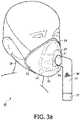
- FIGS. 3a and 3bare front isometric views of masks 40 and 40' according to an embodiment of the present invention.
- the masks 40 and 40'are similar to masks 10 and 10' shown in FIGS. 1 and 2 and have a number of the same components such as body 12 (made of any of the fabric materials described elsewhere herein), opening 11, coupling device 15, first end 9, connector 17, exhaust port 20 and headgear 19.
- the masks 40 and 40'include a nose support 14 which provides assistance in conforming and/or sealing body 12 to the contours of the nasal portion of the user's face.
- nose support 14is positioned over the bridge of the nose of the user.
- the particular nose support 14 shown in FIGS. 3a and 3bis not meant to be limiting and it should be understood that a variety of shapes and configurations for the nose support are contemplated which can be substituted for nose support 14.
- nose support 14is coupled to the interior surface of body 12.
- the mechanism for coupling nose support 14 to body 12can include a wide variety of molding, bonding and fastening mechanisms known in the art such as but not limited to over-molding, gluing, stapling, or stitching.
- Nose support 14can be constructed of a substantially flexible material such as a gel material, a foam material or a pad or cushion-like material.
- masks 40 and 40'also include lip support 16 coupled to body 12.
- Lip support 16provides assistance in conforming and/or sealing body 12 to the contours of the oral portion of the user's face.
- lip support 16is positioned along the outer periphery of the lower lip of the user.
- the particular lip support 16 shown in FIGS. 3a and 3bis not meant to be limiting and it should be understood that a variety of shapes and configurations for the lip support are contemplated which can be substituted for lip support 16.
- lip support 16is coupled to the interior surface of body 12.
- the mechanism for coupling lip support 16 to body 12can include a wide variety of molding, bonding and fastening mechanisms known in the art such as but not limited to over-molding, gluing, stapling, or stitching.
- Lip support 16can be constructed of a substantially flexible material such as a gel material, a foam material or a pad or cushion-like material.
- the particular embodiment shown in FIG. 3afurther includes a chin support, such as chin cuff 18, which provides for restricting movement of the chin of the user.
- Chin cuff 18is integrally connected to the interior surface of body 12.
- the mechanism for connecting chin cuff 18 to body 12can include a wide variety of molding, bonding and fastening mechanisms known in the art such as but not limited to over-molding, gluing, stapling, or stitching.
- Chin cuff 18can be constructed of a substantially flexible material, such as, without limitation, silicone rubber.
- chin cuff 18can include a pad or cushion-like material, or a foam material.
- chin cuff 18can be constructed of a substantially rigid material such as, without limitation, a thermoplastic material. It is contemplated that chin cuff 18 will aid in keeping closed the mouth of the user and providing an effective fit in the oral region of the user's face to prevent gapping and leaking.
- the particular embodiment shown in FIG. 3bincludes a chin support, such as a chin strap 23, which provides for restricting movement of the chin of the user.
- the exemplary chin strap 23 shown in FIG. 3bis coupled to the exterior surface of headgear 19. It is contemplated that chin strap 23 can be permanently or removably coupled to headgear 19.
- the mechanism for connecting chin strap 23 to headgear 19can include a wide variety of fastening mechanisms known in the art such as but not limited to adhesive, snaps, gluing, stapling, or stitching.
- Chin strap 23can be constructed of a substantially flexible material, such as, without limitation, silicone rubber. Further, chin strap 23 can include a pad or cushion-like material, or a foam material. Alternatively, chin strap 23 can be constructed of a substantially rigid material such as a thermoplastic material.
- masks 40 and 40'include opening 11 which functions as a gas inlet.
- rim 22(preferably made of a substantially rigid material such as plastic but also possibly made of a substantially flexible (non-fabric) material as described elsewhere herein such as silicone) extends along the peripheral edge of opening 11.
- Rim 22is preferably coupled to the interior surface of body 12 and provides support for connecting coupling device 15 to opening 11, for carrying gas such as breathing air between masks 40 and 40' and an external gas source (not shown).
- Rim 22preferably includes a threaded mechanism which is structured to receive swivel end 24 of coupling device 15.
- the connector end 17 (which may or may not swivel) of coupling device 15is coupled to an external gas source through one or more conduits such that coupling device 15 functions to transport gas from the external gas source to masks 40 and 40'.
- the thickness of rim 22is less than the thickness of nose support 14 and lip support 16 such that rim 22 will be positioned a distance from the face of the user so that rim 22 does not come into contact with the user's face.
- nose support 14 and lip support 16thus also function as spacers to provide for added comfort.
- FIG. 4is a front isometric view of respiratory mask 50 according to another embodiment of the invention.
- mask 50includes a number of the same components included as part of masks 40 and 40' in FIGS. 3a and 3b , including body 12 (made of any of the fabric materials described elsewhere herein), opening 11, nose support 14, lip support 16, rim 22, coupling device 15, swivel end 24, connector end 17, exhaust port 20 and headgear 19.
- body 12made of any of the fabric materials described elsewhere herein
- opening 11nose support 14
- lip support 16lip support
- coupling device15
- swivel end 24connector end 17, exhaust port 20 and headgear 19
- mask 50includes bridge support 37 which extends upwardly from rim 22 and nose wing 41 is connected to the distal end of bridge support 37.
- Bridge support 37, rim 22 and nose wing 41are preferably coupled to the interior surface (or underside) of body 12 such that body 12 preferably forms a fabric cover over these components.
- nose wing 41is preferably provided between body 12 and a portion of nose support 14.
- bridge support 37is structured to engage the bridge of the user's nose in a direction along the bridge of the user's nose
- nose wing 41is structured to engage the bridge of the user's nose in a direction substantially perpendicular to the direction of bridge support 37.
- Bridge support 37 and nose wing 41provide additional support.
- Bridge support 37 and nose wing 41can be constructed of various materials including, without limitation, a material that is substantially rigid, semi-rigid and/or more rigid than the fabric material used to make body 12. Suitable substantially rigid materials can include, without limitation, polymers, polyurethanes and thermoplastics.
- FIG. 5is a side view of respiratory mask 60 according to a further alternate embodiment of the invention.
- mask 60includes a number of the same components included as part of mask 50 shown in FIG. 4 , including body 12, opening 11, coupling device 15, connector end 17, exhaust port 20 and headgear 19.
- Mask 60does not, however, include nose support 14 and lip support 16 as shown in FIG. 4 .
- mask 60includes rigid or semi-rigid chin cuff 18 (as previously shown in FIG. 3a and described in more detail elsewhere herein). As seen in FIG. 5 , chin cuff 18 is coupled to the bottom of rim 22.
- bridge support 37 having nose wing 41 coupled theretois coupled to the top of rim 22.
- chin cuff 18 engaging the user's chin (as described elsewhere herein) and bridge support 37 and nose wing 41 engaging the user's nose (as described elsewhere herein)rim 22 and a portion of bridge support 37 will be positioned a distance from the user's face for added comfort.
Landscapes
- Health & Medical Sciences (AREA)
- Engineering & Computer Science (AREA)
- Life Sciences & Earth Sciences (AREA)
- Animal Behavior & Ethology (AREA)
- Anesthesiology (AREA)
- Biomedical Technology (AREA)
- Heart & Thoracic Surgery (AREA)
- Hematology (AREA)
- Emergency Medicine (AREA)
- Pulmonology (AREA)
- General Health & Medical Sciences (AREA)
- Public Health (AREA)
- Veterinary Medicine (AREA)
- Manufacturing & Machinery (AREA)
- Mechanical Engineering (AREA)
- Respiratory Apparatuses And Protective Means (AREA)
Description
- A variety of respiratory masks are known which contact the areas surrounding the nose and/or mouth of a human user and that are designed to create an effective fit against the user's face. Typically, gases can be provided at a positive pressure within the mask for consumption by the user. The uses for such masks include high altitude breathing (aviation applications), swimming, mining, fire fighting and various medical diagnostic and therapeutic applications.
- One requisite of many of these masks, (e.g.) particularly medical respiratory masks, is that they provide an effective fit against the user's face and that the mask contours with the user's face to limit or prevent leakage of the gas being supplied. Commonly, in conventional mask configurations, an effective mask-to-face fit has been attained in many instances only with considerable discomfort for the user. This problem is most crucial in those applications, especially medical applications, which require the user to wear the mask continuously for hours or perhaps even days. In such situations, the user often will not tolerate the mask for long durations and therefore optimum therapeutic or diagnostic objectives will not be achieved, or will be achieved with great difficulty and considerable user discomfort.
- Several types of respiratory masks for the types of applications mentioned above are known. Perhaps the most common type of mask incorporates a substantially rigid structure such as a faceplate to support the more flexible sealing member which comes into contact with the user's face, such as a back cushion portion. The rigid structure of the faceplate restricts or limits the ability of the cushion portion to conform to the facial contours of the user. If the fit is not effective, there will be gaps in the mask-to-face interface resulting in gas leaking from the mask at the gaps.
- Considerable force will be required to compress the mask member to close the gaps and attain a satisfactory seal in those areas where the gaps occur. Typically, this required force will be provided by straps that are connected to the mask to securely fit the mask to the face of the user. Such force is undesirable because it produces high pressure points elsewhere on the face of the user where the mask contour is forcibly deformed against the face to conform to the user's facial contours. This will produce considerable user discomfort and possible skin irritation and breakdown anywhere the applied force exceeds the local perfusion pressure, which is the pressure that is sufficient to cut off surface blood flow. Thus, it would be desirable to minimize or eliminate the rigid structure of the mask to improve the ability of the cushion portion to conform to the facial contours of the user and therefore to enhance the fit of the mask to the user's face.
US2921581 discloses a respiratory interface device having a fabric body in the form of a fabric cone. The centre of the cone is provided with an orifice in which a hollow grommet is secured. The grommet provides an anchor for the end of an air hose connected to an air supply line. - Accordingly, it is an object of the present invention to provide a respiratory interface device that overcomes the shortcomings of conventional respiratory interface devices. This object is achieved according to one aspect of the present invention by providing a respiratory interface device according to claim 1.
- These and other objects, features, and characteristics of the present invention, as well as the methods of operation and functions of the related elements of structure and the combination of parts and economies of manufacture, will become more apparent upon consideration of the following description and the appended claims with reference to the accompanying drawings, all of which form a part of this specification, wherein like reference numerals designate corresponding parts in the various figures. It is to be expressly understood, however, that the drawings are for the purpose of illustration and description only and are not intended as a definition of the limits of the invention. As used in the specification and in the claims, the singular form of "a", "an", and "the" include plural referents unless the context clearly dictates otherwise.
FIG. 1 is a front isometric view of a respiratory mask according to an example;FIG. 2 is a front isometric view of a respiratory mask according to an alternative example;FIGS. 3 a and 3b are front isometric views of a respiratory mask according to an embodiment of the invention;FIG. 4 is a front isometric view of a respiratory mask according to another embodiment of the invention; andFIG. 5 is a side view of a respiratory mask according to another alternate embodiment of the invention.- Directional phrases used herein, such as, for example and without limitation, top, bottom, left, right, upper, lower, front, back, and derivatives thereof, relate to the orientation of the elements shown in the drawings and are not limiting upon the claims unless expressly recited therein.
- As employed herein, the term "interface device" refers to any suitable mechanism for transporting gas to and/or from the airway of a user and expressly includes, but is not limited to, non-invasive interface devices such as masks (e.g., without limitation, nasal/oral masks, nasal masks, and full face masks).
- As employed herein, the statement that two or more parts or components are "coupled" or "connected" together shall mean that the parts are joined or operate together either directly or through one or more intermediate parts or components.
- As employed herein, the statement that two or more parts or components "engage" one another shall mean that the parts exert a force against one another either directly or through one or more intermediate parts or components. As employed herein, the term "number" shall mean one or an integer greater than one (i.e., a plurality).
FIG. 1 is a front isometric view ofrespiratory mask 10 according to an example.Respiratory mask 10 includes substantiallyflexible body 12 which, as shown inFIG. 1 , contacts the nasal and oral portions of the user's face. Alternatively,body 12 may contact only one of the nasal portion or oral portion of the user's face.Body 12 is constructed of a fabric material. As employed herein, the term "fabric" shall mean any material that is made from weaving, knitting, crocheting, knotting, or felting fibers together. The material may be stretchable or non-stretchable; coated or uncoated. Uncoated materials preferably will be air breathable such that air may pass through the material (e.g., to allow exhaled gases to pass to the ambient atmosphere). Further, the material can include one layer or material or various layers of material, wherein the layers include the same material or various combinations of different materials. Non-limiting examples of such fabric materials include, without limitation, polyesters.- Also as shown in
FIG. 1 ,body 12 includes opening 11 which functions as a gas inlet.Shell 13 is coupled tobody 12 along the periphery of opening 11.Shell 13 is also constructed of a fabric material. Suitable fabrics for use in makingshell 13 can include those described elsewhere herein for use in constructingbody 12. In an embodiment, the fabric used to makeshell 13 can be the same fabric as that used to makebody 12. Further, in this embodiment,shell 13 can be integrally coupled tobody 12. In another embodiment, the fabric used to makeshell 13 can be of a different, more rigid fabric than that used to makebody 12. In another particular embodiment,body 12 is made of a soft, stretchable fabric to promote comfort andshell 13 is made of a stiffer, non-stretchable but uncoated fabric to allow exhaled gases to escape to the ambient atmosphere. - Also as shown in
FIG. 1 ,shell 13 extends outwardly frombody 12 and is structured to receivetherein coupling device 15. First end 9 ofcoupling device 15 is received intoshell 13. It is contemplated that the inside diameter ofshell 13 is sized such that first end 9 ofcoupling device 15 fits snuggly therein. In an embodiment, a fluid sealing mechanism (not shown) including, without limitation, an adhesive material, such as glue, or a flow restrictor, such as a clamp or the like, can be applied to first end 9 ofcoupling device 15 and/orshell 13 to enhance the seal betweencoupling device 15 andshell 13 and minimize or preclude leakage. Positioned opposite of first end 9 ofcoupling device 15 isconnector end 17 which is capable of being coupled to an external gas source (not shown) through one or more conduits. - In an exemplary embodiment,
connector end 17 can include a swivel connector for connecting to the one or more conduits. It is contemplated that the external gas source can encompass, without limitation, any gas delivery or gas generation system capable of supplying gas for consumption by a user. Non-limiting examples of various gas delivery therapies can include but are not limited to continuous positive airway pressure (CPAP) therapy, automatic positive airway pressure (APAP) therapy and bi-level positive airway pressure (BiPAP) therapy.Coupling device 15 is employed to carry gas such as breathing air between the external gas source andmask 10.Coupling device 15 includes a venting mechanism, such asexhaust port 20, as shown inFIG. 1 , for exhausting gas expired by the user to the atmosphere. Exhaust port 20 includes a plurality of small openings that allow the exhaust gas expired by the user to exitmask 10 to the atmosphere. Theparticular exhaust port 20 shown inFIG. 1 is not meant to be limiting and it should be understood that the present invention contemplates a variety of different venting mechanisms that could be employed to exhaust the gas expired by the user to the atmosphere, such as, without limitation, an exhaust valve. Thus, a variety of venting mechanisms may be substituted forexhaust port 20.- Further, the
particular coupling device 15 shown inFIG. 1 is not meant to be limiting and it should be understood that the present invention contemplates a variety of different coupling devices that could be received within, either permanently or selectively,shell 13 to carry gas to or frommask 10. Thus, a variety of coupling devices may be substituted for thecoupling device 15. - Also, as shown in
FIG. 1 ,mask 10 includesheadgear 19 attached tobody 12 to securebody 12 on each side to the user's face.Headgear 19 can be structured in a wide variety of ways to securebody 12 to the user's face and can be constructed of a wide variety of fabrics known in the art such as, without limitation, any fabric having the ability to stretch and/or flex. In the embodiment as shown inFIG. 1 ,headgear 19 attaches to each side ofbody 12 and fits around the circumference of the head of the user. Also as shown inFIG. 1 ,headgear 19 is integrally coupled tobody 12. - Alternatively,
headgear 19 can be coupled tobody 12 using a wide variety of molding, bonding and fastening mechanisms such as, without limitation, sewing or stitching, snaps, straps, adhesive, and the like. In an embodiment, the same fabric can be used to constructbody 12,shell 13 andheadgear 19. In other embodiments,body 12 and/orshell 13 can be made of a less permeable fabric thanheadgear 19. In a particular embodiment,headgear 19 can be made of a more stretchable fabric thanbody 12. Theparticular headgear 19 shown inFIG. 1 is not meant to be limiting and it should be understood that the present invention contemplates a wide variety of different headgears, (e.g., adjustable or non-adjustable or combinations thereof, integrally coupled or detachably coupled) that could be employed to securebody 12 to the face of the user. Thus, a variety of headgears known in the art or hereinafter developed may be substituted forheadgear 19. FIG. 2 is a front isometric view of mask 10' according to another example. As shown inFIG. 2 , mask 10' includes a number of the same components included as part ofmask 10 inFIG. 1 , includingbody 12, opening 11,shell 13,coupling device 15,connector end 17,exhaust port 20 andheadgear 19. In addition, as shown inFIG. 2 , mask 10' includesframe 21.Frame 21 is formed along the periphery of opening 11 and extends outwardly (e.g., radially) therefrom.Frame 21 can be formed on the interior surface of body 12 (e.g., the surface that comes into contact with the user's face) and/orframe 21 can be formed on the exterior surface of body 12 (as shown inFIG. 2 ).Frame 21 can be formed using various molding and fastening techniques known in the art.- The
exemplary frame 21, as shown inFIG. 2 , is coupled to the outer surface ofbody 12 and is in the shape of a starfish. Theparticular frame 21 shown inFIG. 2 is not meant to be limiting and it should be understood that the present invention encompasses a wide variety of shapes and configurations that could be used as substitutions forframe 21.Frame 21 may be constructed of a variety of materials including, without limitation, the fabric materials described elsewhere herein forbody 12 andshell 13.Frame 21 also may be constructed of a flexible, solid material, such as, without limitation, a material having greater rigidity than the materials used to makebody 12 and/or shell 13 (e.g., silicone, polyurethane or foam). In an alternate embodiment, a layer of a rigid material, such as, without limitation, plastic, metal or wire can be inserted betweenframe 21 and the surface ofbody 12. It is contemplated thatframe 21 in the various embodiments described will provide enhanced support to improve the effective fit of mask 10' to the user's face. FIGS. 3a and3b are front isometric views ofmasks 40 and 40' according to an embodiment of the present invention. Themasks 40 and 40' are similar tomasks 10 and 10' shown inFIGS. 1 and2 and have a number of the same components such as body 12 (made of any of the fabric materials described elsewhere herein), opening 11,coupling device 15, first end 9,connector 17,exhaust port 20 andheadgear 19. In addition, as shown inFIGS. 3a and3b , themasks 40 and 40' include anose support 14 which provides assistance in conforming and/or sealingbody 12 to the contours of the nasal portion of the user's face.- As shown in
FIGS. 3a and3b ,nose support 14 is positioned over the bridge of the nose of the user. Theparticular nose support 14 shown inFIGS. 3a and3b is not meant to be limiting and it should be understood that a variety of shapes and configurations for the nose support are contemplated which can be substituted fornose support 14. As also shown inFIGS. 3a and3b ,nose support 14 is coupled to the interior surface ofbody 12. The mechanism forcoupling nose support 14 tobody 12 can include a wide variety of molding, bonding and fastening mechanisms known in the art such as but not limited to over-molding, gluing, stapling, or stitching.Nose support 14 can be constructed of a substantially flexible material such as a gel material, a foam material or a pad or cushion-like material. - As shown in
FIGS. 3a and3b , masks 40 and 40' also includelip support 16 coupled tobody 12.Lip support 16 provides assistance in conforming and/or sealingbody 12 to the contours of the oral portion of the user's face. As shown inFIGS. 3a and3b ,lip support 16 is positioned along the outer periphery of the lower lip of the user. Theparticular lip support 16 shown inFIGS. 3a and3b is not meant to be limiting and it should be understood that a variety of shapes and configurations for the lip support are contemplated which can be substituted forlip support 16. As also shown inFIGS. 3a and3b ,lip support 16 is coupled to the interior surface ofbody 12. The mechanism for couplinglip support 16 tobody 12 can include a wide variety of molding, bonding and fastening mechanisms known in the art such as but not limited to over-molding, gluing, stapling, or stitching.Lip support 16 can be constructed of a substantially flexible material such as a gel material, a foam material or a pad or cushion-like material. - The particular embodiment shown in
FIG. 3a further includes a chin support, such aschin cuff 18, which provides for restricting movement of the chin of the user.Chin cuff 18 is integrally connected to the interior surface ofbody 12. The mechanism for connectingchin cuff 18 tobody 12 can include a wide variety of molding, bonding and fastening mechanisms known in the art such as but not limited to over-molding, gluing, stapling, or stitching.Chin cuff 18 can be constructed of a substantially flexible material, such as, without limitation, silicone rubber. Further,chin cuff 18 can include a pad or cushion-like material, or a foam material. Alternatively,chin cuff 18 can be constructed of a substantially rigid material such as, without limitation, a thermoplastic material. It is contemplated thatchin cuff 18 will aid in keeping closed the mouth of the user and providing an effective fit in the oral region of the user's face to prevent gapping and leaking. - The particular embodiment shown in
FIG. 3b includes a chin support, such as a chin strap 23, which provides for restricting movement of the chin of the user. The exemplary chin strap 23 shown inFIG. 3b is coupled to the exterior surface ofheadgear 19. It is contemplated that chin strap 23 can be permanently or removably coupled toheadgear 19. The mechanism for connecting chin strap 23 toheadgear 19 can include a wide variety of fastening mechanisms known in the art such as but not limited to adhesive, snaps, gluing, stapling, or stitching. Chin strap 23 can be constructed of a substantially flexible material, such as, without limitation, silicone rubber. Further, chin strap 23 can include a pad or cushion-like material, or a foam material. Alternatively, chin strap 23 can be constructed of a substantially rigid material such as a thermoplastic material. - Further, as shown in
FIGS. 3a and3b , masks 40 and 40' include opening 11 which functions as a gas inlet. In the embodiment as shown inFIGS. 3a and3b , rim 22 (preferably made of a substantially rigid material such as plastic but also possibly made of a substantially flexible (non-fabric) material as described elsewhere herein such as silicone) extends along the peripheral edge ofopening 11.Rim 22 is preferably coupled to the interior surface ofbody 12 and provides support for connectingcoupling device 15 to opening 11, for carrying gas such as breathing air betweenmasks 40 and 40' and an external gas source (not shown).Rim 22 preferably includes a threaded mechanism which is structured to receive swivel end 24 ofcoupling device 15. The connector end 17 (which may or may not swivel) ofcoupling device 15 is coupled to an external gas source through one or more conduits such thatcoupling device 15 functions to transport gas from the external gas source tomasks 40 and 40'. - In one particular embodiment, the thickness of
rim 22 is less than the thickness ofnose support 14 andlip support 16 such that rim 22 will be positioned a distance from the face of the user so thatrim 22 does not come into contact with the user's face. In this embodiment,nose support 14 andlip support 16 thus also function as spacers to provide for added comfort. FIG. 4 is a front isometric view ofrespiratory mask 50 according to another embodiment of the invention. As seen inFIG. 4 ,mask 50 includes a number of the same components included as part ofmasks 40 and 40' inFIGS. 3a and3b , including body 12 (made of any of the fabric materials described elsewhere herein), opening 11,nose support 14,lip support 16,rim 22,coupling device 15,swivel end 24,connector end 17,exhaust port 20 andheadgear 19. In addition, as shown inFIG. 4 ,mask 50 includesbridge support 37 which extends upwardly fromrim 22 andnose wing 41 is connected to the distal end ofbridge support 37.Bridge support 37,rim 22 andnose wing 41, are preferably coupled to the interior surface (or underside) ofbody 12 such thatbody 12 preferably forms a fabric cover over these components. In addition,nose wing 41 is preferably provided betweenbody 12 and a portion ofnose support 14.- As seen in
FIG. 4 ,bridge support 37 is structured to engage the bridge of the user's nose in a direction along the bridge of the user's nose, andnose wing 41 is structured to engage the bridge of the user's nose in a direction substantially perpendicular to the direction ofbridge support 37. In this manner,bridge support 37 andnose wing 41 provide additional support.Bridge support 37 andnose wing 41 can be constructed of various materials including, without limitation, a material that is substantially rigid, semi-rigid and/or more rigid than the fabric material used to makebody 12. Suitable substantially rigid materials can include, without limitation, polymers, polyurethanes and thermoplastics. FIG. 5 is a side view ofrespiratory mask 60 according to a further alternate embodiment of the invention. As seen inFIG. 5 ,mask 60 includes a number of the same components included as part ofmask 50 shown inFIG. 4 , includingbody 12, opening 11,coupling device 15,connector end 17,exhaust port 20 andheadgear 19.Mask 60 does not, however, includenose support 14 andlip support 16 as shown inFIG. 4 . In addition, as shown inFIG. 5 ,mask 60 includes rigid or semi-rigid chin cuff 18 (as previously shown inFIG. 3a and described in more detail elsewhere herein). As seen inFIG. 5 ,chin cuff 18 is coupled to the bottom ofrim 22. As described elsewhere herein,bridge support 37 havingnose wing 41 coupled thereto is coupled to the top ofrim 22. As a result ofchin cuff 18 engaging the user's chin (as described elsewhere herein) andbridge support 37 andnose wing 41 engaging the user's nose (as described elsewhere herein),rim 22 and a portion ofbridge support 37 will be positioned a distance from the user's face for added comfort.- While preferred embodiments of the invention have been described and illustrated above, it should be understood that these are exemplary of the invention and are not to be considered as limiting. Accordingly, the invention is not to be considered as limited by the foregoing description but is only limited by the scope of the appended claims.
Claims (9)
- A respiratory interface device, comprising:a fabric body (12) structured to accommodate and contact one or both of a nasal and oral region of a user's face, the fabric body having an opening (11) formed therein, the opening being structured to receive a coupling device for delivering a gas to the respiratory interface device; anda first non-fabric support element coupled to the interior surface of the fabric body and arranged to engage a nasal or oral portion of a user's face,characterized in that the respiratory interface device further comprises a second non-fabric support element in the form of a rim (22), the rim being structured to extend around the opening (11) and the rim being structured to receive the coupling device (15) for delivering a gas to the respiratory interface device.
- The respiratory interface device of claim 1 wherein the first non-fabric support element (16) comprises a nose support element (14), the nose support element being structured to engage a nose of a user.
- The respiratory interface device of claim 1 wherein the first non-fabric support element comprises a lip support element (16), the lip support element being structured to engage a face of the user below a mouth of the user.
- The respiratory interface device of claim 1, wherein the first non-fabric support element further comprises a non-fabric bridge support element (37) coupled to the fabric body (12), the bridge support element having a bridge support portion coupled to and extending from the rim (22) and structured to engage a bridge of the user's nose along a first direction, the bridge support element further having a nose wing portion (41) coupled to the bridge support portion for engaging the bridge of the user's nose along a second direction substantially perpendicular to the first direction.
- The respiratory interface device of claim 1, wherein the first non-fabric support element further comprises a non-fabric nose support element (14) coupled to the fabric body (12), the nose support element being structured to engage a nose of a user, and the respiratory interface device further comprises a third non-fabric support element that comprises a non-fabric lip support element (16) coupled to the fabric body, the lip support element being structured to engage a face of the user below a mouth of the user.
- The respiratory interface device of claim 5, wherein a thickness of the rim (22) is less than a thickness of each of the nose support element (14) and the lip support element (16).
- The respiratory interface device of claim 5, wherein the respiratory interface device comprises a fourth non-fabric support element that comprises a non-fabric chin support element (18) coupled to the fabric body (12), the chin support element being structured to engage a chin portion of the user's face.
- The respiratory interface device of claim 1, wherein the respiratory interface device comprises a third non-fabric support element that comprises a non-fabric chin support element (18) coupled to the fabric body (12), the chin support element being structured to engage a chin portion of the user's face, the non-fabric chin support element being coupled to the rim (22) for spacing the rim from a face of the user.
- The respiratory interface device of claim 8, wherein the first non-fabric support element comprises a bridge support element (37) coupled to the fabric body (12), the bridge support element having a bridge support portion coupled to and extending from the rim and structured to engage a bridge of a user's nose along a first direction, the bridge support element further having a nose wing portion (41) coupled to the bridge support portion for engaging the bridge of the user's nose along a second direction substantially perpendicular to the first direction.
Applications Claiming Priority (3)
| Application Number | Priority Date | Filing Date | Title |
|---|---|---|---|
| US13971308P | 2008-12-22 | 2008-12-22 | |
| PCT/IB2009/055260WO2010073138A1 (en) | 2008-12-22 | 2009-11-21 | Respiratory interface device with flexible cover |
| EP09764585.7AEP2379148B1 (en) | 2008-12-22 | 2009-11-21 | Respiratory interface device with flexible cover |
Related Parent Applications (3)
| Application Number | Title | Priority Date | Filing Date |
|---|---|---|---|
| EP09764585.7ADivision-IntoEP2379148B1 (en) | 2008-12-22 | 2009-11-21 | Respiratory interface device with flexible cover |
| EP09764585.7ADivisionEP2379148B1 (en) | 2008-12-22 | 2009-11-21 | Respiratory interface device with flexible cover |
| EP09764585.7Division | 2009-11-21 |
Publications (3)
| Publication Number | Publication Date |
|---|---|
| EP2444113A2 EP2444113A2 (en) | 2012-04-25 |
| EP2444113A3 EP2444113A3 (en) | 2012-08-15 |
| EP2444113B1true EP2444113B1 (en) | 2018-08-01 |
Family
ID=41665049
Family Applications (2)
| Application Number | Title | Priority Date | Filing Date |
|---|---|---|---|
| EP12150605.9ANot-in-forceEP2444113B1 (en) | 2008-12-22 | 2009-11-21 | Respiratory interface device with flexible cover |
| EP09764585.7ANot-in-forceEP2379148B1 (en) | 2008-12-22 | 2009-11-21 | Respiratory interface device with flexible cover |
Family Applications After (1)
| Application Number | Title | Priority Date | Filing Date |
|---|---|---|---|
| EP09764585.7ANot-in-forceEP2379148B1 (en) | 2008-12-22 | 2009-11-21 | Respiratory interface device with flexible cover |
Country Status (6)
| Country | Link |
|---|---|
| US (1) | US9919120B2 (en) |
| EP (2) | EP2444113B1 (en) |
| JP (1) | JP5750047B2 (en) |
| CN (1) | CN102264424A (en) |
| BR (1) | BRPI0918105A2 (en) |
| WO (1) | WO2010073138A1 (en) |
Families Citing this family (57)
| Publication number | Priority date | Publication date | Assignee | Title |
|---|---|---|---|---|
| US9308343B2 (en)* | 2008-02-19 | 2016-04-12 | Circadiance, Llc | Respiratory mask with disposable cloth body |
| FR2952582A1 (en)* | 2009-11-16 | 2011-05-20 | Deltalyo & Valmy | DISPOSABLE OBJECT FOR SINGLE USE |
| GB2489379B (en) | 2009-12-23 | 2016-01-13 | Fisher & Paykel Healthcare Ltd | Patient interface and headgear |
| NZ701943A (en)* | 2010-09-01 | 2016-05-27 | Resmed Ltd | Mask system |
| US9308339B2 (en)* | 2010-12-20 | 2016-04-12 | Koninklijke Philips N.V. | Patient interface having wrap around fabric headgear |
| US10603456B2 (en) | 2011-04-15 | 2020-03-31 | Fisher & Paykel Healthcare Limited | Interface comprising a nasal sealing portion |
| GB2529079B (en) | 2011-04-15 | 2016-06-22 | Fisher & Paykel Healthcare Ltd | An elbow assembly for a mask |
| EP2731655B1 (en) | 2011-07-12 | 2017-07-12 | ResMed Limited | Textile mask systems |
| EP3851146B1 (en) | 2011-08-22 | 2025-04-30 | ResMed Pty Ltd | Manufactured to shape headgear and masks |
| US10143817B2 (en)* | 2011-12-06 | 2018-12-04 | Koninklijke Philips N.V. | Cushion having adjustable stabilization member |
| GB2553475B8 (en) | 2012-08-08 | 2019-01-02 | Fisher & Paykel Healthcare Ltd | Headgear for patient interface |
| EP4279106A3 (en) | 2012-09-04 | 2024-01-17 | Fisher & Paykel Healthcare Limited | Valsalva mask |
| US10821250B2 (en) | 2012-11-16 | 2020-11-03 | Fisher & Paykel Healthcare Limited | Nasal seal and respiratory interface |
| US20150314095A1 (en)* | 2012-12-13 | 2015-11-05 | Koninklijke Philips N.V. | Patient interface cushion with integral straps |
| EP4397346B1 (en)* | 2013-03-04 | 2025-10-08 | Fisher & Paykel Healthcare Limited | Patient interfaces with condensation reducing or compensating arrangements |
| US10004866B2 (en) | 2013-03-15 | 2018-06-26 | Lucy Carol Davis | Facial mask apparatus and method of making |
| US11235119B2 (en) | 2013-03-15 | 2022-02-01 | Lucy Carol Davis | Facial mask apparatus and method of making |
| US20140261430A1 (en)* | 2013-03-15 | 2014-09-18 | Lucy Carol Davis | Facial Mask Apparatus and Method of Making |
| US11235120B2 (en) | 2013-03-15 | 2022-02-01 | Lucy Carol Davis | Facial mask apparatus with removable filter |
| CA2919449C (en) | 2013-08-05 | 2022-04-12 | Fisher & Paykel Healthcare Limited | Seal for a patient interface, interface assemblies and aspects thereof |
| US9776023B2 (en) | 2013-09-24 | 2017-10-03 | 3M Innovative Properties Company | Respiratory mask having a nose support extension |
| CN106413788B (en) | 2014-06-17 | 2019-12-20 | 费雪派克医疗保健有限公司 | Patient interface |
| WO2016032343A1 (en) | 2014-08-25 | 2016-03-03 | Fisher & Paykel Healthcare Limited | Respiratory mask and related portions, components or sub-assemblies |
| JP6931326B2 (en) | 2014-09-16 | 2021-09-01 | フィッシャー アンド ペイケル ヘルスケア リミテッド | Headgear assembly and interface assembly with headgear |
| US10828452B2 (en) | 2014-09-16 | 2020-11-10 | Fisher & Paykel Healthcare Limited | Intramold headgear |
| US10646680B2 (en) | 2014-09-19 | 2020-05-12 | Fisher & Paykel Healthcare Limited | Headgear assemblies and interface assemblies with headgear |
| US20180071476A1 (en)* | 2014-11-19 | 2018-03-15 | Koninklijke Philips N.V. | Frame/headgear adjustment assembly |
| EP3223894B1 (en) | 2014-11-26 | 2020-12-23 | ResMed Pty Ltd | Textile patient interface |
| US10828451B2 (en) | 2015-06-18 | 2020-11-10 | Koninklijke Philips N.V. | Passive nose bridge pressure distributing insert |
| CN118987436A (en) | 2015-07-20 | 2024-11-22 | 瑞思迈私人有限公司 | Patient interface with volume reduction member |
| US10994090B2 (en) | 2015-09-04 | 2021-05-04 | Fisher & Paykel Healthcare Limited | Patient interfaces |
| CN105381530A (en)* | 2015-12-09 | 2016-03-09 | 东莞市毅达电子有限公司 | a flexible mask |
| WO2017120643A1 (en)* | 2016-01-14 | 2017-07-20 | Resmed Limited | Oro-nasal patient interface |
| EP3430284B1 (en) | 2016-03-16 | 2021-07-14 | Fisher & Paykel Healthcare Limited | Directional lock for interface headgear arrangement |
| AU2017234345B2 (en) | 2016-03-16 | 2022-03-03 | Fisher & Paykel Healthcare Limited | Intra-mould substrate |
| SG11201807699TA (en) | 2016-03-16 | 2018-10-30 | Fisher & Paykel Healthcare Ltd | Strap assembly, strap connector, headgear, headgear assembly, method of forming headgear, tubular connector, patient interface and method of joining straps |
| WO2018056844A1 (en)* | 2016-09-26 | 2018-03-29 | Fisher & Paykel Healthcare Limited | A respiratory system and mask interface background |
| USD823455S1 (en) | 2017-02-23 | 2018-07-17 | Fisher & Paykel Healthcare Limited | Cushion assembly for breathing mask assembly |
| USD823454S1 (en) | 2017-02-23 | 2018-07-17 | Fisher & Paykel Healthcare Limited | Cushion assembly for breathing mask assembly |
| USD824020S1 (en) | 2017-02-23 | 2018-07-24 | Fisher & Paykel Healthcare Limited | Cushion assembly for breathing mask assembly |
| USD901673S1 (en) | 2017-03-09 | 2020-11-10 | Fisher & Paykel Healthcare Limited | Frame and breathing tube assembly for a nasal mask |
| USD874646S1 (en) | 2017-03-09 | 2020-02-04 | Fisher & Paykel Healthcare Limited | Headgear component for a nasal mask assembly |
| US12102764B2 (en) | 2017-06-26 | 2024-10-01 | Fisher & Paykel Healthcare Limited | Respiratory mask system |
| USD875242S1 (en) | 2017-09-20 | 2020-02-11 | Fisher & Paykel Healthcare Limited | Nasal mask and breathing tube set |
| USD855793S1 (en) | 2017-09-20 | 2019-08-06 | Fisher & Paykel Healthcare Limited | Frame for a nasal mask |
| WO2019123348A1 (en) | 2017-12-21 | 2019-06-27 | Fisher & Paykel Healthcare Limited | Respiratory mask system |
| CN108245756A (en)* | 2018-01-26 | 2018-07-06 | 王泽华 | A kind of comfortable ventilating type oxygen mask |
| EP3765135B1 (en) | 2018-03-16 | 2024-11-27 | Fisher & Paykel Healthcare Limited | Headgear with lock disengagement mechanism |
| USD884153S1 (en) | 2018-04-04 | 2020-05-12 | Fisher & Paykel Healthcare Limited | Frame for a mask assembly |
| US12115314B2 (en) | 2018-10-16 | 2024-10-15 | ResMed Pty Ltd | Textile seal-forming structure with multiple curvatures |
| MX2021004369A (en) | 2018-10-16 | 2021-09-21 | ResMed Pty Ltd | PATIENT INTERFACE. |
| US12059528B2 (en) | 2018-10-16 | 2024-08-13 | ResMed Pty Ltd | Textile seal-forming structure with multiple curvatures |
| US11844887B2 (en) | 2019-10-16 | 2023-12-19 | ResMed Pty Ltd | Textile seal-forming structure with multiple curvatures |
| WO2021137765A1 (en) | 2019-12-31 | 2021-07-08 | ResMed Asia Pte Ltd | A patient interface formed from a textile construction and including a stiffened portion to provide for customization |
| US12256057B2 (en) | 2019-12-31 | 2025-03-18 | ResMed Asia Pte. Ltd. | Positioning, stabilising, and interfacing structures and system incorporating same |
| US20220095718A1 (en)* | 2020-09-25 | 2022-03-31 | The Board Of Regents Of The University Of Oklahoma | External Brace for Enhancing Fit and Filtration Efficacy of Face Masks |
| JP7750813B2 (en)* | 2022-09-30 | 2025-10-07 | 日本光電工業株式会社 | Gas inhalation mask |
Citations (1)
| Publication number | Priority date | Publication date | Assignee | Title |
|---|---|---|---|---|
| US2921581A (en)* | 1955-10-21 | 1960-01-19 | John J Swearingen | Adhesive-type oxygen mask |
Family Cites Families (33)
| Publication number | Priority date | Publication date | Assignee | Title |
|---|---|---|---|---|
| GB150232A (en)* | 1920-02-10 | 1920-09-02 | Cecil Rosling | Improvements in breathing apparatus |
| US1878464A (en)* | 1929-07-24 | 1932-09-20 | Frederick R M Bulmer | Mask |
| GB438863A (en)* | 1934-08-18 | 1935-11-25 | Bartels & Rieger Hermet G M B | Improvements in or relating to respirators |
| US2307730A (en)* | 1941-09-11 | 1943-01-05 | Herbert J Heribert | Gas mask |
| US3130722A (en)* | 1959-09-08 | 1964-04-28 | Protective Treat S Inc | Respiratory mask |
| DE1944548C3 (en)* | 1969-09-02 | 1980-04-03 | Laerdal, Asmund S., Stavanger (Norwegen) | Collapsible ventilation mask and transport bag therefor |
| CA2068925A1 (en) | 1991-05-21 | 1992-11-22 | Amad Tayebi | Breathing mask |
| US6272690B1 (en)* | 1994-11-23 | 2001-08-14 | Michael J. Carey | Head covering |
| US5857460A (en)* | 1996-03-14 | 1999-01-12 | Beth Israel Deaconess Medical Center, Inc. | Gas-sensing mask |
| US5884336A (en)* | 1997-06-20 | 1999-03-23 | Stout; Kathleen K. | Cold weather mask including a mouth seal having a direct flow through porous hygroscopic material |
| US6041782A (en) | 1997-06-24 | 2000-03-28 | 3M Innovative Properties Company | Respiratory mask having comfortable inner cover web |
| US6016804A (en)* | 1997-10-24 | 2000-01-25 | Scott Technologies, Inc. | Respiratory mask and method of making thereof |
| US6102039A (en) | 1997-12-01 | 2000-08-15 | 3M Innovative Properties Company | Molded respirator containing sorbent particles |
| US5918598A (en)* | 1998-04-10 | 1999-07-06 | Belfer; William A. | Strapless respiratory facial mask for customizing to the wearer's face |
| JP3106128B1 (en) | 1999-04-30 | 2000-11-06 | 浄 高本 | mask |
| US6357440B1 (en)* | 1999-06-16 | 2002-03-19 | Mallinckrodt Inc. | Pliable respiratory mask |
| US6604524B1 (en)* | 1999-10-19 | 2003-08-12 | 3M Innovative Properties Company | Manner of attaching component elements to filtration material such as may be utilized in respiratory masks |
| US6718982B2 (en)* | 2001-05-07 | 2004-04-13 | Mark A. Smith | Face mask incorporating respiratory flow sensor |
| US20050199240A1 (en)* | 2003-01-09 | 2005-09-15 | Matthew Hall | Flexible full-face mask for CPAP treatment |
| GB0300875D0 (en) | 2003-01-15 | 2003-02-12 | Smiths Group Plc | Face masks |
| US9789274B2 (en) | 2003-07-09 | 2017-10-17 | Resmed R&D Germany Gmbh | Respiratory mask arrangement as well as headband arrangement and respiratory gas evacuation device for a respiratory mask |
| JP2005304574A (en) | 2004-04-16 | 2005-11-04 | Ookisu Medical:Kk | Mask |
| DE102004030068B3 (en)* | 2004-06-23 | 2005-06-23 | Drägerwerk AG | Respiration mask for continuous positive airway pressure respiration device with respiration gases supplied via bandage attaching mask to head of patient |
| WO2006024249A1 (en)* | 2004-09-03 | 2006-03-09 | Weinmann Geräte für Medizin GmbH & Co. KG | Respiratory device |
| DE102004055433B3 (en)* | 2004-11-17 | 2005-11-17 | Drägerwerk AG | Breathing mask with integrated suction area |
| US20060199457A1 (en)* | 2005-03-01 | 2006-09-07 | Kimberly-Clark Worldwide, Inc. | Cloth-like biaxial stretch nonwoven |
| US7743768B2 (en)* | 2005-12-20 | 2010-06-29 | Ric Investments, Llc | Patient interface device with dampening cushion |
| AU2007205869A1 (en)* | 2006-01-19 | 2007-07-26 | John C. Jeppesen Dmd, Inc. | Method and device for treating sleep apnea |
| US20080142015A1 (en) | 2006-01-27 | 2008-06-19 | David Groll | Apparatus to provide continuous positive airway pressure |
| WO2007109837A1 (en)* | 2006-03-24 | 2007-10-04 | Resmed Ltd | Air delivery conduit |
| US20090065005A1 (en)* | 2007-09-06 | 2009-03-12 | Ades Abraham J | Nose mask assembly to be worn during sleep having a suspension support bracket and a retractable line |
| US20110000492A1 (en) | 2008-03-04 | 2011-01-06 | Resmed Ltd | Foam respiratory mask |
| US8113201B2 (en)* | 2008-06-30 | 2012-02-14 | Kimberly-Clark Worldwide, Inc. | Collapse resistant respirator |
- 2009
- 2009-11-21JPJP2011541653Apatent/JP5750047B2/ennot_activeExpired - Fee Related
- 2009-11-21WOPCT/IB2009/055260patent/WO2010073138A1/enactiveApplication Filing
- 2009-11-21EPEP12150605.9Apatent/EP2444113B1/ennot_activeNot-in-force
- 2009-11-21USUS13/132,453patent/US9919120B2/enactiveActive
- 2009-11-21BRBRPI0918105Apatent/BRPI0918105A2/ennot_activeIP Right Cessation
- 2009-11-21EPEP09764585.7Apatent/EP2379148B1/ennot_activeNot-in-force
- 2009-11-21CNCN2009801519662Apatent/CN102264424A/enactivePending
Patent Citations (1)
| Publication number | Priority date | Publication date | Assignee | Title |
|---|---|---|---|---|
| US2921581A (en)* | 1955-10-21 | 1960-01-19 | John J Swearingen | Adhesive-type oxygen mask |
Also Published As
| Publication number | Publication date |
|---|---|
| EP2379148B1 (en) | 2016-10-19 |
| JP5750047B2 (en) | 2015-07-15 |
| JP2012513229A (en) | 2012-06-14 |
| EP2444113A2 (en) | 2012-04-25 |
| US20110247628A1 (en) | 2011-10-13 |
| BRPI0918105A2 (en) | 2015-11-24 |
| CN102264424A (en) | 2011-11-30 |
| US9919120B2 (en) | 2018-03-20 |
| EP2444113A3 (en) | 2012-08-15 |
| EP2379148A1 (en) | 2011-10-26 |
| WO2010073138A1 (en) | 2010-07-01 |
Similar Documents
| Publication | Publication Date | Title |
|---|---|---|
| EP2444113B1 (en) | Respiratory interface device with flexible cover | |
| AU2020203017B2 (en) | Interface Comprising a Rolling Nasal Bridge Portion | |
| US9056177B2 (en) | Respiratory interface with flexing faceplate | |
| US9844639B2 (en) | Patient interface device including a coating adhesive layer |
Legal Events
| Date | Code | Title | Description |
|---|---|---|---|
| AC | Divisional application: reference to earlier application | Ref document number:2379148 Country of ref document:EP Kind code of ref document:P | |
| AK | Designated contracting states | Kind code of ref document:A2 Designated state(s):AT BE BG CH CY CZ DE DK EE ES FI FR GB GR HR HU IE IS IT LI LT LU LV MC MK MT NL NO PL PT RO SE SI SK SM TR | |
| PUAI | Public reference made under article 153(3) epc to a published international application that has entered the european phase | Free format text:ORIGINAL CODE: 0009012 | |
| PUAL | Search report despatched | Free format text:ORIGINAL CODE: 0009013 | |
| AK | Designated contracting states | Kind code of ref document:A3 Designated state(s):AT BE BG CH CY CZ DE DK EE ES FI FR GB GR HR HU IE IS IT LI LT LU LV MC MK MT NL NO PL PT RO SE SI SK SM TR | |
| RIC1 | Information provided on ipc code assigned before grant | Ipc:A61M 16/06 20060101AFI20120710BHEP Ipc:B29C 45/16 20060101ALI20120710BHEP | |
| 17P | Request for examination filed | Effective date:20130215 | |
| RAP1 | Party data changed (applicant data changed or rights of an application transferred) | Owner name:KONINKLIJKE PHILIPS N.V. | |
| 17Q | First examination report despatched | Effective date:20170221 | |
| GRAP | Despatch of communication of intention to grant a patent | Free format text:ORIGINAL CODE: EPIDOSNIGR1 | |
| INTG | Intention to grant announced | Effective date:20180223 | |
| GRAS | Grant fee paid | Free format text:ORIGINAL CODE: EPIDOSNIGR3 | |
| GRAA | (expected) grant | Free format text:ORIGINAL CODE: 0009210 | |
| AC | Divisional application: reference to earlier application | Ref document number:2379148 Country of ref document:EP Kind code of ref document:P | |
| AK | Designated contracting states | Kind code of ref document:B1 Designated state(s):AT BE BG CH CY CZ DE DK EE ES FI FR GB GR HR HU IE IS IT LI LT LU LV MC MK MT NL NO PL PT RO SE SI SK SM TR | |
| REG | Reference to a national code | Ref country code:GB Ref legal event code:FG4D | |
| REG | Reference to a national code | Ref country code:CH Ref legal event code:EP Ref country code:AT Ref legal event code:REF Ref document number:1023587 Country of ref document:AT Kind code of ref document:T Effective date:20180815 | |
| REG | Reference to a national code | Ref country code:IE Ref legal event code:FG4D | |
| REG | Reference to a national code | Ref country code:DE Ref legal event code:R096 Ref document number:602009053653 Country of ref document:DE | |
| REG | Reference to a national code | Ref country code:NL Ref legal event code:MP Effective date:20180801 | |
| REG | Reference to a national code | Ref country code:LT Ref legal event code:MG4D | |
| REG | Reference to a national code | Ref country code:AT Ref legal event code:MK05 Ref document number:1023587 Country of ref document:AT Kind code of ref document:T Effective date:20180801 | |
| PG25 | Lapsed in a contracting state [announced via postgrant information from national office to epo] | Ref country code:FI Free format text:LAPSE BECAUSE OF FAILURE TO SUBMIT A TRANSLATION OF THE DESCRIPTION OR TO PAY THE FEE WITHIN THE PRESCRIBED TIME-LIMIT Effective date:20180801 Ref country code:NL Free format text:LAPSE BECAUSE OF FAILURE TO SUBMIT A TRANSLATION OF THE DESCRIPTION OR TO PAY THE FEE WITHIN THE PRESCRIBED TIME-LIMIT Effective date:20180801 Ref country code:PL Free format text:LAPSE BECAUSE OF FAILURE TO SUBMIT A TRANSLATION OF THE DESCRIPTION OR TO PAY THE FEE WITHIN THE PRESCRIBED TIME-LIMIT Effective date:20180801 Ref country code:LT Free format text:LAPSE BECAUSE OF FAILURE TO SUBMIT A TRANSLATION OF THE DESCRIPTION OR TO PAY THE FEE WITHIN THE PRESCRIBED TIME-LIMIT Effective date:20180801 Ref country code:NO Free format text:LAPSE BECAUSE OF FAILURE TO SUBMIT A TRANSLATION OF THE DESCRIPTION OR TO PAY THE FEE WITHIN THE PRESCRIBED TIME-LIMIT Effective date:20181101 Ref country code:BG Free format text:LAPSE BECAUSE OF FAILURE TO SUBMIT A TRANSLATION OF THE DESCRIPTION OR TO PAY THE FEE WITHIN THE PRESCRIBED TIME-LIMIT Effective date:20181101 Ref country code:SE Free format text:LAPSE BECAUSE OF FAILURE TO SUBMIT A TRANSLATION OF THE DESCRIPTION OR TO PAY THE FEE WITHIN THE PRESCRIBED TIME-LIMIT Effective date:20180801 Ref country code:AT Free format text:LAPSE BECAUSE OF FAILURE TO SUBMIT A TRANSLATION OF THE DESCRIPTION OR TO PAY THE FEE WITHIN THE PRESCRIBED TIME-LIMIT Effective date:20180801 Ref country code:IS Free format text:LAPSE BECAUSE OF FAILURE TO SUBMIT A TRANSLATION OF THE DESCRIPTION OR TO PAY THE FEE WITHIN THE PRESCRIBED TIME-LIMIT Effective date:20181201 Ref country code:GR Free format text:LAPSE BECAUSE OF FAILURE TO SUBMIT A TRANSLATION OF THE DESCRIPTION OR TO PAY THE FEE WITHIN THE PRESCRIBED TIME-LIMIT Effective date:20181102 | |
| PG25 | Lapsed in a contracting state [announced via postgrant information from national office to epo] | Ref country code:ES Free format text:LAPSE BECAUSE OF FAILURE TO SUBMIT A TRANSLATION OF THE DESCRIPTION OR TO PAY THE FEE WITHIN THE PRESCRIBED TIME-LIMIT Effective date:20180801 Ref country code:HR Free format text:LAPSE BECAUSE OF FAILURE TO SUBMIT A TRANSLATION OF THE DESCRIPTION OR TO PAY THE FEE WITHIN THE PRESCRIBED TIME-LIMIT Effective date:20180801 Ref country code:LV Free format text:LAPSE BECAUSE OF FAILURE TO SUBMIT A TRANSLATION OF THE DESCRIPTION OR TO PAY THE FEE WITHIN THE PRESCRIBED TIME-LIMIT Effective date:20180801 | |
| PG25 | Lapsed in a contracting state [announced via postgrant information from national office to epo] | Ref country code:IT Free format text:LAPSE BECAUSE OF FAILURE TO SUBMIT A TRANSLATION OF THE DESCRIPTION OR TO PAY THE FEE WITHIN THE PRESCRIBED TIME-LIMIT Effective date:20180801 Ref country code:EE Free format text:LAPSE BECAUSE OF FAILURE TO SUBMIT A TRANSLATION OF THE DESCRIPTION OR TO PAY THE FEE WITHIN THE PRESCRIBED TIME-LIMIT Effective date:20180801 Ref country code:RO Free format text:LAPSE BECAUSE OF FAILURE TO SUBMIT A TRANSLATION OF THE DESCRIPTION OR TO PAY THE FEE WITHIN THE PRESCRIBED TIME-LIMIT Effective date:20180801 Ref country code:CZ Free format text:LAPSE BECAUSE OF FAILURE TO SUBMIT A TRANSLATION OF THE DESCRIPTION OR TO PAY THE FEE WITHIN THE PRESCRIBED TIME-LIMIT Effective date:20180801 | |
| REG | Reference to a national code | Ref country code:DE Ref legal event code:R097 Ref document number:602009053653 Country of ref document:DE | |
| PG25 | Lapsed in a contracting state [announced via postgrant information from national office to epo] | Ref country code:SK Free format text:LAPSE BECAUSE OF FAILURE TO SUBMIT A TRANSLATION OF THE DESCRIPTION OR TO PAY THE FEE WITHIN THE PRESCRIBED TIME-LIMIT Effective date:20180801 Ref country code:SM Free format text:LAPSE BECAUSE OF FAILURE TO SUBMIT A TRANSLATION OF THE DESCRIPTION OR TO PAY THE FEE WITHIN THE PRESCRIBED TIME-LIMIT Effective date:20180801 Ref country code:DK Free format text:LAPSE BECAUSE OF FAILURE TO SUBMIT A TRANSLATION OF THE DESCRIPTION OR TO PAY THE FEE WITHIN THE PRESCRIBED TIME-LIMIT Effective date:20180801 | |
| PLBE | No opposition filed within time limit | Free format text:ORIGINAL CODE: 0009261 | |
| STAA | Information on the status of an ep patent application or granted ep patent | Free format text:STATUS: NO OPPOSITION FILED WITHIN TIME LIMIT | |
| REG | Reference to a national code | Ref country code:CH Ref legal event code:PL | |
| 26N | No opposition filed | Effective date:20190503 | |
| GBPC | Gb: european patent ceased through non-payment of renewal fee | Effective date:20181121 | |
| PG25 | Lapsed in a contracting state [announced via postgrant information from national office to epo] | Ref country code:MC Free format text:LAPSE BECAUSE OF FAILURE TO SUBMIT A TRANSLATION OF THE DESCRIPTION OR TO PAY THE FEE WITHIN THE PRESCRIBED TIME-LIMIT Effective date:20180801 Ref country code:LU Free format text:LAPSE BECAUSE OF NON-PAYMENT OF DUE FEES Effective date:20181121 | |
| REG | Reference to a national code | Ref country code:BE Ref legal event code:MM Effective date:20181130 | |
| REG | Reference to a national code | Ref country code:IE Ref legal event code:MM4A | |
| PG25 | Lapsed in a contracting state [announced via postgrant information from national office to epo] | Ref country code:LI Free format text:LAPSE BECAUSE OF NON-PAYMENT OF DUE FEES Effective date:20181130 Ref country code:CH Free format text:LAPSE BECAUSE OF NON-PAYMENT OF DUE FEES Effective date:20181130 Ref country code:SI Free format text:LAPSE BECAUSE OF FAILURE TO SUBMIT A TRANSLATION OF THE DESCRIPTION OR TO PAY THE FEE WITHIN THE PRESCRIBED TIME-LIMIT Effective date:20180801 | |
| PG25 | Lapsed in a contracting state [announced via postgrant information from national office to epo] | Ref country code:IE Free format text:LAPSE BECAUSE OF NON-PAYMENT OF DUE FEES Effective date:20181121 | |
| PG25 | Lapsed in a contracting state [announced via postgrant information from national office to epo] | Ref country code:BE Free format text:LAPSE BECAUSE OF NON-PAYMENT OF DUE FEES Effective date:20181130 | |
| PG25 | Lapsed in a contracting state [announced via postgrant information from national office to epo] | Ref country code:GB Free format text:LAPSE BECAUSE OF NON-PAYMENT OF DUE FEES Effective date:20181121 | |
| PG25 | Lapsed in a contracting state [announced via postgrant information from national office to epo] | Ref country code:MT Free format text:LAPSE BECAUSE OF NON-PAYMENT OF DUE FEES Effective date:20181121 | |
| PG25 | Lapsed in a contracting state [announced via postgrant information from national office to epo] | Ref country code:TR Free format text:LAPSE BECAUSE OF FAILURE TO SUBMIT A TRANSLATION OF THE DESCRIPTION OR TO PAY THE FEE WITHIN THE PRESCRIBED TIME-LIMIT Effective date:20180801 | |
| PG25 | Lapsed in a contracting state [announced via postgrant information from national office to epo] | Ref country code:PT Free format text:LAPSE BECAUSE OF FAILURE TO SUBMIT A TRANSLATION OF THE DESCRIPTION OR TO PAY THE FEE WITHIN THE PRESCRIBED TIME-LIMIT Effective date:20180801 | |
| PG25 | Lapsed in a contracting state [announced via postgrant information from national office to epo] | Ref country code:MK Free format text:LAPSE BECAUSE OF NON-PAYMENT OF DUE FEES Effective date:20180801 Ref country code:HU Free format text:LAPSE BECAUSE OF FAILURE TO SUBMIT A TRANSLATION OF THE DESCRIPTION OR TO PAY THE FEE WITHIN THE PRESCRIBED TIME-LIMIT; INVALID AB INITIO Effective date:20091121 Ref country code:CY Free format text:LAPSE BECAUSE OF FAILURE TO SUBMIT A TRANSLATION OF THE DESCRIPTION OR TO PAY THE FEE WITHIN THE PRESCRIBED TIME-LIMIT Effective date:20180801 | |
| PGFP | Annual fee paid to national office [announced via postgrant information from national office to epo] | Ref country code:FR Payment date:20201126 Year of fee payment:12 Ref country code:DE Payment date:20201130 Year of fee payment:12 | |
| REG | Reference to a national code | Ref country code:DE Ref legal event code:R119 Ref document number:602009053653 Country of ref document:DE | |
| PG25 | Lapsed in a contracting state [announced via postgrant information from national office to epo] | Ref country code:DE Free format text:LAPSE BECAUSE OF NON-PAYMENT OF DUE FEES Effective date:20220601 | |
| PG25 | Lapsed in a contracting state [announced via postgrant information from national office to epo] | Ref country code:FR Free format text:LAPSE BECAUSE OF NON-PAYMENT OF DUE FEES Effective date:20211130 |