EP2441403A1 - Rod-shaped implant, in particular for spinal stabilization, method and tool for producing the same - Google Patents
Rod-shaped implant, in particular for spinal stabilization, method and tool for producing the sameDownload PDFInfo
- Publication number
- EP2441403A1 EP2441403A1EP12151170AEP12151170AEP2441403A1EP 2441403 A1EP2441403 A1EP 2441403A1EP 12151170 AEP12151170 AEP 12151170AEP 12151170 AEP12151170 AEP 12151170AEP 2441403 A1EP2441403 A1EP 2441403A1
- Authority
- EP
- European Patent Office
- Prior art keywords
- rod
- component
- tool
- shaped implant
- cavity
- Prior art date
- Legal status (The legal status is an assumption and is not a legal conclusion. Google has not performed a legal analysis and makes no representation as to the accuracy of the status listed.)
- Granted
Links
- 239000007943implantSubstances0.000titleclaimsabstractdescription40
- 230000006641stabilisationEffects0.000titleclaimsabstractdescription26
- 238000011105stabilizationMethods0.000titleclaimsabstractdescription26
- 238000000034methodMethods0.000titleclaimsdescription12
- 239000000463materialSubstances0.000claimsabstractdescription68
- 239000004033plasticSubstances0.000claimsabstractdescription20
- 229920003023plasticPolymers0.000claimsabstractdescription20
- 238000002844meltingMethods0.000claimsabstractdescription8
- 230000008018meltingEffects0.000claimsabstractdescription8
- 238000004519manufacturing processMethods0.000claimsdescription15
- 238000002347injectionMethods0.000claimsdescription13
- 239000007924injectionSubstances0.000claimsdescription13
- 238000001746injection mouldingMethods0.000claimsdescription5
- 239000000835fiberSubstances0.000claimsdescription3
- 239000002184metalSubstances0.000claims1
- 230000004927fusionEffects0.000description8
- 238000003466weldingMethods0.000description7
- 210000000988bone and boneAnatomy0.000description4
- 230000007704transitionEffects0.000description3
- 238000005452bendingMethods0.000description2
- 230000001747exhibiting effectEffects0.000description2
- 239000007769metal materialSubstances0.000description2
- 229920001692polycarbonate urethanePolymers0.000description2
- 239000002639bone cementSubstances0.000description1
- 238000001816coolingMethods0.000description1
- 230000001419dependent effectEffects0.000description1
- 238000011161developmentMethods0.000description1
- 230000018109developmental processEffects0.000description1
- 229920002457flexible plasticPolymers0.000description1
- 238000012986modificationMethods0.000description1
- 230000004048modificationEffects0.000description1
- 239000012768molten materialSubstances0.000description1
- 239000007787solidSubstances0.000description1
- 238000002604ultrasonographyMethods0.000description1
Images


Classifications
- A—HUMAN NECESSITIES
- A61—MEDICAL OR VETERINARY SCIENCE; HYGIENE
- A61B—DIAGNOSIS; SURGERY; IDENTIFICATION
- A61B17/00—Surgical instruments, devices or methods
- A61B17/56—Surgical instruments or methods for treatment of bones or joints; Devices specially adapted therefor
- A61B17/58—Surgical instruments or methods for treatment of bones or joints; Devices specially adapted therefor for osteosynthesis, e.g. bone plates, screws or setting implements
- A61B17/68—Internal fixation devices, including fasteners and spinal fixators, even if a part thereof projects from the skin
- A61B17/70—Spinal positioners or stabilisers, e.g. stabilisers comprising fluid filler in an implant
- A61B17/7001—Screws or hooks combined with longitudinal elements which do not contact vertebrae
- A61B17/7002—Longitudinal elements, e.g. rods
- A61B17/7019—Longitudinal elements having flexible parts, or parts connected together, such that after implantation the elements can move relative to each other
- A61B17/7031—Longitudinal elements having flexible parts, or parts connected together, such that after implantation the elements can move relative to each other made wholly or partly of flexible material
- A—HUMAN NECESSITIES
- A61—MEDICAL OR VETERINARY SCIENCE; HYGIENE
- A61B—DIAGNOSIS; SURGERY; IDENTIFICATION
- A61B17/00—Surgical instruments, devices or methods
- A61B17/56—Surgical instruments or methods for treatment of bones or joints; Devices specially adapted therefor
- A61B17/58—Surgical instruments or methods for treatment of bones or joints; Devices specially adapted therefor for osteosynthesis, e.g. bone plates, screws or setting implements
- A61B17/68—Internal fixation devices, including fasteners and spinal fixators, even if a part thereof projects from the skin
- A61B17/84—Fasteners therefor or fasteners being internal fixation devices
- A61B17/86—Pins or screws or threaded wires; nuts therefor
- A—HUMAN NECESSITIES
- A61—MEDICAL OR VETERINARY SCIENCE; HYGIENE
- A61F—FILTERS IMPLANTABLE INTO BLOOD VESSELS; PROSTHESES; DEVICES PROVIDING PATENCY TO, OR PREVENTING COLLAPSING OF, TUBULAR STRUCTURES OF THE BODY, e.g. STENTS; ORTHOPAEDIC, NURSING OR CONTRACEPTIVE DEVICES; FOMENTATION; TREATMENT OR PROTECTION OF EYES OR EARS; BANDAGES, DRESSINGS OR ABSORBENT PADS; FIRST-AID KITS
- A61F2/00—Filters implantable into blood vessels; Prostheses, i.e. artificial substitutes or replacements for parts of the body; Appliances for connecting them with the body; Devices providing patency to, or preventing collapsing of, tubular structures of the body, e.g. stents
- A61F2/02—Prostheses implantable into the body
- A61F2/30—Joints
- A61F2/44—Joints for the spine, e.g. vertebrae, spinal discs
- B—PERFORMING OPERATIONS; TRANSPORTING
- B29—WORKING OF PLASTICS; WORKING OF SUBSTANCES IN A PLASTIC STATE IN GENERAL
- B29C—SHAPING OR JOINING OF PLASTICS; SHAPING OF MATERIAL IN A PLASTIC STATE, NOT OTHERWISE PROVIDED FOR; AFTER-TREATMENT OF THE SHAPED PRODUCTS, e.g. REPAIRING
- B29C45/00—Injection moulding, i.e. forcing the required volume of moulding material through a nozzle into a closed mould; Apparatus therefor
- B29C45/16—Making multilayered or multicoloured articles
- B29C45/1635—Making multilayered or multicoloured articles using displaceable mould parts, e.g. retractable partition between adjacent mould cavities
- B—PERFORMING OPERATIONS; TRANSPORTING
- B29—WORKING OF PLASTICS; WORKING OF SUBSTANCES IN A PLASTIC STATE IN GENERAL
- B29C—SHAPING OR JOINING OF PLASTICS; SHAPING OF MATERIAL IN A PLASTIC STATE, NOT OTHERWISE PROVIDED FOR; AFTER-TREATMENT OF THE SHAPED PRODUCTS, e.g. REPAIRING
- B29C45/00—Injection moulding, i.e. forcing the required volume of moulding material through a nozzle into a closed mould; Apparatus therefor
- B29C45/16—Making multilayered or multicoloured articles
- B29C45/1657—Making multilayered or multicoloured articles using means for adhering or bonding the layers or parts to each other
- A—HUMAN NECESSITIES
- A61—MEDICAL OR VETERINARY SCIENCE; HYGIENE
- A61B—DIAGNOSIS; SURGERY; IDENTIFICATION
- A61B17/00—Surgical instruments, devices or methods
- A61B2017/00526—Methods of manufacturing
- B—PERFORMING OPERATIONS; TRANSPORTING
- B29—WORKING OF PLASTICS; WORKING OF SUBSTANCES IN A PLASTIC STATE IN GENERAL
- B29L—INDEXING SCHEME ASSOCIATED WITH SUBCLASS B29C, RELATING TO PARTICULAR ARTICLES
- B29L2031/00—Other particular articles
- B29L2031/753—Medical equipment; Accessories therefor
Definitions
- the inventionrelates to a rod-shaped implant, in particular for spinal stabilization, to a method and a tool for producing such a rod-shaped implant.
- the rod-shaped implantincludes a first component comprising a first material and a second component comprising a second material, wherein at least the first material is a plastic material and wherein the first and the second component are connected by melting at least the first component to the second component.
- the connection between the componentsis non-detachable so that a single-piece rod-shaped implant is provided.
- a rod-shaped implant made of a plastic material for the dynamic stabilization of portions of the spinal columnis known, for example, from US 2007/0093820 A1 , US 2007/0161999 A1 and US 2007/0270843 A1 .
- the rod-shaped implants of the prior artare made of a plastic material having specific properties such as bending flexibility.
- the size of these implants, in particular their lengthis dimensioned such that, when anchored in the vertebrae, they extend along one or several motion segments of the spine for allowing a limited motion of the vertebrae of the respective motion segments. If a larger portion of the spine has to be stabilized several individual rods having different properties may be used for different portions of the spine.
- the rod-shaped implant according to the inventionhas the advantage that portions having different properties, in particular having a different flexibility are combined in a single-piece implant. This facilitates the handling of the implant for the surgeon because rod connectors are not needed.
- Using the method according to the inventionallows to combine different materials within a single piece rod-shaped implant which can be specially designed according to the clinical requirements.
- Fig. 1shows a spinal column 100 with vertebrae 101, 102, etc. and intervertebral discs 103, 104, etc.
- the intervertebral discsare removed and the space between the vertebrae is filled with fusion cages 105, 106, etc. which may be filled with bone cement or bone graft.
- pedicle screws 107, 108, 109are screwed into the adjacent vertebrae and a rod-shaped implant in the form of a spinal stabilization rod 1 is accommodated in the receiving portions of the pedicle screws to connect the pedicle screws to each other.
- the spinal stabilization rod 1extends along the fusion zone comprising the fusion cages 105, 106 through a transition zone into a flexible zone.
- the spinal stabilization rod 1includes substantially rigid portion 1c for the fixation of the fusion zone, a transition portion 1b which is less stiff than the rigid portion 1c and a flexible portion 1a which is flexible in such a way that it allows a limited motion of the motion segments stabilized thereby.
- the spinal stabilization rod 1having portions with different flexibility the vertebrae which are neighboring vertebrae to the fusion zone can be protected from overloading.
- the spinal stabilization rod 1is shown in Fig. 2 with two portions 1a, 1b having different properties.
- the spinal stabilization rodis substantially cylindrical.
- the first portion 1ais made of a first material and the second portion 1b is made of a second material.
- the first portion 1a and the second portion 1bare connected at a connection surface 2.
- the first materialis a bio-compatible plastic material exhibiting specific properties, in particular bending flexibility.
- the second materialis also a bio-compatible plastic material exhibiting properties which are different from those of the first material.
- the second portion 1bmay be less flexible than the first portion 1a.
- Exemplary materialsare PCU (poly carbonate urethane) with different degrees of hardness, for example 65D and 55D.
- connection surface 2has in the embodiment shown a circular cross section.
- the first portion 1ais connected to the second portion 1b at the connection surface 2 by means of melting at least one of the materials of the first portion 1a or the second portion 1b.
- a permanent mechanical connectionis established between the portions 1 a and 1b.
- the connectionis not detachable by loads or tension acting upon the rod under all circumstances of the intended clinical use.
- the spinal stabilization rod 1 as shown in Fig. 2is not limited to consist only of two portions 1a and 1b having different properties. It may have a third portion 1c as shown in Fig. 1 with high stiffness which can also be made from a bio-compatible plastic material. The rod 1 may also have alternating portions of flexible and stiff portions along the zone of the spinal column which is to be stabilized.
- the pedicle screwsare anchored into the vertebrae.
- the spinal stabilization rod 1is inserted into the receiving portions of the pedicle screws and fixed therein by clamping.
- the stabilization rodprovides a rigid fixation in the fusion zone and flexibility to allow a motion of the vertebrae in the transition zone and the flexible zone with a different degree of mobility, respectively.
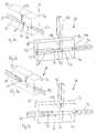
- Fig. 3shows a tool for producing a spinal stabilization rod with two portions 1a, 1b having different properties.
- the toolis in an opened state and shown in section.
- the tool 3comprises a first tool part 3a and a second tool part 3b each having a cylindrical cavity 4a, 4b which is open to respective surfaces 31a, 31b of the tool parts 3a, 3b, facing each other.
- the cavities 4a, 4bare dimensioned such that they define the mold pattern or die for the portions 1a, 1b of the rod 1.
- An injection channel 41a, 41 bopens into the cavity 4a, 4b from a free surface of the first and second tool part, respectively.
- the tool 3further comprises two injection nozzles 5a, 5b which are suitable for injecting molten material into the cavities 4a, 4b via the injection channels 41a, 41 b.
- a method for producing the spinal stabilization rod according to Fig. 2is shown in Figs. 4 and 5 .
- the methoduses the known technique of injection molding.
- the tool parts 3a and 3bare closed as shown in Fig. 4 .
- a valve or a slidemay be provided to temporarily separate cavity 4a from cavity 4b.
- the valveis closed and the molten first material is injected via the nozzle and the injection channel 41 a into the cavity 4a.
- the valveis opened and as shown in Fig. 5 the second material for the second portion 1b is injected via the nozzle 5b and the injection channel 41b into the cavity 4b.
- the connection surface 2 where the first material encounters the second material in a molten or at least plastically deformable statea mechanical connection is established through melting which leads to the permanent connection between portion 1a and portion 1b.
- the so produced spinal stabilization rod 1is cooled down, if necessary by a separate cooling device (not shown), and after having reached the final solid state, the first and second tool part 3a and 3b are moved apart to open the tool 3 to take out the rod 1.
- the sequencemay be also changed depending on the type of material.
- an adjustment of the conditions necessary for injection molding of the specific materialssuch as temperature, time intervals, pressure etc. is possible. The adjustment can be made independently for each of the materials used.
- the toolis connected to a control device which is designed to be able to control the parameters.
- the tool 3may consist of further tool parts if the rod consists of several components having different properties.
- the shape of the cavities and hence the shape of the rodcan vary. For example, rods having any type of cross section such as square, rectangular, oval etc. can be produced.
- Figs. 6a to 7bshow a second embodiment of the tool.
- the tool 30 according to Figs. 6a to 7bdiffers from the tool 3 of the first embodiment in the design of the second tool part 3b'.
- the first tool part 3ais identical to the tool part 3a of the first embodiment and its descripton will not be repeated.
- Like parts of the tool 30 which correspond to the parts of tool 3are indicated with the same reference numerals.
- the cavity 4b' of the second tool part 3b'comprises a first section 40 sized similar to the cavity 4a of the first tool part 3a and adjacent to the first section 40 a second section 41 having a larger diameter and extending to the outer surface 32.
- a core puller 50is provided fitting into the second section 41 of the cavity and including a core 51.
- the core 51has a length which is dimensioned such that when the core puller 50 is fully inserted into the second section 41 the core 51 extends into the first cavity 4a of the first tool part 3a to a certain extent.
- the toolis closed and the core puller 50 is pushed into the second cavity 4b such that the core 51 extends into the first cavity 4a. Then molten first material is injected via the nozzle 5a and the injection channel 41 a into the first cavity thereby surrounding the end portion of the core 51.
- the core puller 50is retracted and the second material is injected via the nozzle 5b and the injection channel 41b into the second cavity 4b.
- the molten second materialflows into the first cavity 4a to the portion which was occupied by the end portion of end core 51 during the injection molding step of the first material.
- Figs. 8a to 8eshow various shapes with increased surface area of the connection surface 2' by providing a core 51 with a corresponding shape.
- Fig. 8ashows a cylindrical connection surface 2
- Fig. 8bshows a connection surface having a truncated cone shape
- Fig. 8cshows a connection surface having an undercut 2a.
- Fig. 8dshows a connection surface with a christmas-tree-shape
- Fig. 8eshows a connection surface having a tree-shape with undercut.
- any other shapesare conceivable.
- Fig. 9ashows a second embodiment of the spinal stabilization rod.
- the spinal stabilization rod 1'differs from the spinal stabilization rod 1 according to Fig. 2 in that the two components 1a' and 1b' having different properties are not connected at a front side of the cylindrical rod but are connected along the whole outer surface.
- the first component 1a'forms an inner cylinder and the second component 1b' forms an outer hollow cylinder connected to the inner cylinder at the surface.
- component 1a'is comprised of a stiffer material whereas the second component 1b' is comprised of a material having a lesser degree of stiffness or hardness.
- the first component 1a'can be made of plastic material having a degree of hardness of 65D and the second component is made of a material having a degree of hardness of 55D.
- This rodcan be used in particular in such applications where the stiffer component 1a' has to provide a high degree of tension stiffness for fusion.
- a stiffer rodis hardly fixable in the receiving portion of the pedicle screw.
- any clamping devicesuch as a clamping tooth or projection 60 as shown in Fig. 9b , can penetrate into the more flexible material. This results in a secure clamping.
- Fig. 10shows a third embodiment of the spinal stabilization rod.
- the spinal stabilization rod 1"comprises in radial direction several zones 1a", 1b, 1b", 1c" having different properties.
- zone 1a"can comprise fibers 70 to provide a specific stiffness.
- Zone 1b"can have oriented fibers 71 and zone 1c" is comprised of a material with a lesser degree of stiffness.
- the tool required for the production thereofis adapted to form the rod with different zones by injection molding of different materials to connect them at the surface area by melting. Any combination and shape of zones is conceivable.
- the inventionis not limited to plastic materials. It is applicable also for a rod-shaped implant comprising a first component made of a metallic material and a second component made of a plastic material which is melted to engage the metallic material at a connection surface.
- the inventionis further not limited to be used with a specific type of pedicle screw. Any type of known bone anchors, for example monoaxial and polyaxial screws can be used.
- the rod-shaped implantis composed of rod-parts 10a, 10b which are made of different materials, similar to the implants of foregoing embodiments.
- the rod partsare prefabricated.
- the implantis manufactured by welding the rod parts together at the connection surface 20, which is one end surface of the rod parts.
- ultrasound welding or infrared weldingare preferable, but any other welding technique can also be used.
- a permanent connection between the rod partsis established through melting.
- a bulge 21 of materialusually appears in the course of the manufacturing procedure which results from the flow of the material during the welding step. In a still further manufacturing step this bulge is removed by a post treatment, such as, for example, grinding.
Landscapes
- Health & Medical Sciences (AREA)
- Orthopedic Medicine & Surgery (AREA)
- Engineering & Computer Science (AREA)
- Life Sciences & Earth Sciences (AREA)
- Surgery (AREA)
- Neurology (AREA)
- Biomedical Technology (AREA)
- Heart & Thoracic Surgery (AREA)
- Animal Behavior & Ethology (AREA)
- Veterinary Medicine (AREA)
- Public Health (AREA)
- General Health & Medical Sciences (AREA)
- Medical Informatics (AREA)
- Molecular Biology (AREA)
- Nuclear Medicine, Radiotherapy & Molecular Imaging (AREA)
- Manufacturing & Machinery (AREA)
- Mechanical Engineering (AREA)
- Cardiology (AREA)
- Oral & Maxillofacial Surgery (AREA)
- Transplantation (AREA)
- Vascular Medicine (AREA)
- Prostheses (AREA)
- Surgical Instruments (AREA)
Abstract
Description
- The invention relates to a rod-shaped implant, in particular for spinal stabilization, to a method and a tool for producing such a rod-shaped implant. The rod-shaped implant includes a first component comprising a first material and a second component comprising a second material, wherein at least the first material is a plastic material and wherein the first and the second component are connected by melting at least the first component to the second component. The connection between the components is non-detachable so that a single-piece rod-shaped implant is provided.
- A rod-shaped implant made of a plastic material for the dynamic stabilization of portions of the spinal column is known, for example, from
US 2007/0093820 A1 ,US 2007/0161999 A1 andUS 2007/0270843 A1 . - The rod-shaped implants of the prior art are made of a plastic material having specific properties such as bending flexibility. The size of these implants, in particular their length is dimensioned such that, when anchored in the vertebrae, they extend along one or several motion segments of the spine for allowing a limited motion of the vertebrae of the respective motion segments. If a larger portion of the spine has to be stabilized several individual rods having different properties may be used for different portions of the spine.
- It is further known to connect two metallic rod or a metallic rod and a flexible plastic rod with a rod connector device.
- It is the object of the invention to provide a rod-shaped implant, in particular for the stabilization of the spine, a method and a tool for the production thereof which allows the stabilization of bone segments or motion segments of the spinal column with various degrees of flexibility along different portions of the bone segments or the spinal column.
- The object is solved by a rod-shaped implant according to
claim 1, a method according to claim 9 and a tool according to claim 13. Further developments of the invention are given in the dependent claims. - The rod-shaped implant according to the invention has the advantage that portions having different properties, in particular having a different flexibility are combined in a single-piece implant. This facilitates the handling of the implant for the surgeon because rod connectors are not needed.
- Using the method according to the invention allows to combine different materials within a single piece rod-shaped implant which can be specially designed according to the clinical requirements.
- Further features and advantages of the invention will become apparent frein the following detailed description of embodiments in conjunction with the accompanying drawings. In the drawings:
- Fig. 1
- shows a schematic view of the human spinal column together with a spinal stabilization and fusion system.
- Fig. 2
- shows a schematic side view of the rod-shaped implant according to a first embodiment.
- Fig. 3
- shows a perspective view in section of a tool for the production of the rod-shaped implant according to
Fig. 2 in an opened state. - Fig. 4
- shows the tool according to
Fig. 3 in a closed state during production of the first component of the rod-shaped implant. - Fig. 5
- shows the tool of
Fig. 3 and4 in the closed state during production of the second component of the rod-shaped implant. - Fig. 6a
- shows a second embodiment of the tool in a perspective sectional view in a first step producing the first component of the rod-shaped implant.
- Fig. 6b
- shows the tool of
Fig. 6a in the same state in a different perspective view. - Fig. 7a
- shows the tool of
Fig. 6a after producing of the first component in a second state. - Fig. 7b
- shows the tool of
Fig. 7a during production of the second component in a different perspective view. - Fig. 8a to Fig. 8e
- show modifications of the rod-shaped implant of
Fig. 2 wherein the surface of contact of the first component and the second component is increased. - Fig. 9a
- shows a schematic view of a second embodiment of the rod-shaped implant.
- Fig. 9b
- shows a schematic view of the fixation of the rod-shaped implant of
Fig. 9a . - Fig. 10
- shows a further embodiment of the rod-shaped implant.
- Fig. 11
- shows a still further embodiment of the rod-shaped implant during an intermediate step of manufacturing.
- Fig. 12
- shows the implant of
Fig. 11 during a further intermediate step of manufacturing. Fig. 1 shows aspinal column 100 withvertebrae intervertebral discs fusion cages system pedicle screws spinal stabilization rod 1 is accommodated in the receiving portions of the pedicle screws to connect the pedicle screws to each other. Thespinal stabilization rod 1 shown inFig. 1 extends along the fusion zone comprising thefusion cages spinal stabilization rod 1 includes substantially rigid portion 1c for the fixation of the fusion zone, a transition portion 1b which is less stiff than the rigid portion 1c and aflexible portion 1a which is flexible in such a way that it allows a limited motion of the motion segments stabilized thereby. With thespinal stabilization rod 1 having portions with different flexibility the vertebrae which are neighboring vertebrae to the fusion zone can be protected from overloading.- The
spinal stabilization rod 1 is shown inFig. 2 with twoportions 1a, 1b having different properties. In the embodiment shown the spinal stabilization rod is substantially cylindrical. Thefirst portion 1a is made of a first material and the second portion 1b is made of a second material. Thefirst portion 1a and the second portion 1b are connected at aconnection surface 2. The first material is a bio-compatible plastic material exhibiting specific properties, in particular bending flexibility. The second material is also a bio-compatible plastic material exhibiting properties which are different from those of the first material. With reference toFig. 1 the second portion 1b may be less flexible than thefirst portion 1a. Exemplary materials are PCU (poly carbonate urethane) with different degrees of hardness, for example 65D and 55D. - The
connection surface 2 has in the embodiment shown a circular cross section. Thefirst portion 1a is connected to the second portion 1b at theconnection surface 2 by means of melting at least one of the materials of thefirst portion 1a or the second portion 1b. As a result thereof a permanent mechanical connection is established between theportions 1 a and 1b. The connection is not detachable by loads or tension acting upon the rod under all circumstances of the intended clinical use. - The
spinal stabilization rod 1 as shown inFig. 2 is not limited to consist only of twoportions 1a and 1b having different properties. It may have a third portion 1c as shown inFig. 1 with high stiffness which can also be made from a bio-compatible plastic material. Therod 1 may also have alternating portions of flexible and stiff portions along the zone of the spinal column which is to be stabilized. - In use, as shown in
Fig. 1 , the pedicle screws are anchored into the vertebrae. Then, thespinal stabilization rod 1 is inserted into the receiving portions of the pedicle screws and fixed therein by clamping. The stabilization rod provides a rigid fixation in the fusion zone and flexibility to allow a motion of the vertebrae in the transition zone and the flexible zone with a different degree of mobility, respectively. Fig. 3 shows a tool for producing a spinal stabilization rod with twoportions 1a, 1b having different properties. The tool is in an opened state and shown in section.- The
tool 3 comprises a first tool part 3a and a second tool part 3b each having acylindrical cavity 4a, 4b which is open to respective surfaces 31a, 31b of the tool parts 3a, 3b, facing each other. Thecavities 4a, 4b are dimensioned such that they define the mold pattern or die for theportions 1a, 1b of therod 1. An injection channel 41a, 41 b opens into thecavity 4a, 4b from a free surface of the first and second tool part, respectively. - The
tool 3 further comprises twoinjection nozzles cavities 4a, 4b via the injection channels 41a, 41 b. - A method for producing the spinal stabilization rod according to
Fig. 2 is shown inFigs. 4 and 5 . The method uses the known technique of injection molding. For the production, the tool parts 3a and 3b are closed as shown inFig. 4 . A valve or a slide (not shown) may be provided to temporarilyseparate cavity 4a from cavity 4b. In a first step which is shown inFig. 4 the valve is closed and the molten first material is injected via the nozzle and the injection channel 41 a into thecavity 4a. - Thereafter, the valve is opened and as shown in
Fig. 5 the second material for the second portion 1b is injected via thenozzle 5b and the injection channel 41b into the cavity 4b. At theconnection surface 2 where the first material encounters the second material in a molten or at least plastically deformable state a mechanical connection is established through melting which leads to the permanent connection betweenportion 1a and portion 1b. - After the two materials are injected and adhered together at the
connection surface 2, the so producedspinal stabilization rod 1 is cooled down, if necessary by a separate cooling device (not shown), and after having reached the final solid state, the first and second tool part 3a and 3b are moved apart to open thetool 3 to take out therod 1. - It is preferable to first inject the material for the stiffer rod portion and then to inject the material for the more flexible rod portion, but the sequence may be also changed depending on the type of material. With the process, an adjustment of the conditions necessary for injection molding of the specific materials such as temperature, time intervals, pressure etc. is possible. The adjustment can be made independently for each of the materials used.
- Preferably the tool is connected to a control device which is designed to be able to control the parameters.
- The
tool 3 may consist of further tool parts if the rod consists of several components having different properties. The shape of the cavities and hence the shape of the rod can vary. For example, rods having any type of cross section such as square, rectangular, oval etc. can be produced. Figs. 6a to 7b show a second embodiment of the tool. Thetool 30 according toFigs. 6a to 7b differs from thetool 3 of the first embodiment in the design of the second tool part 3b'. The first tool part 3a is identical to the tool part 3a of the first embodiment and its descripton will not be repeated. Like parts of thetool 30 which correspond to the parts oftool 3 are indicated with the same reference numerals.- The cavity 4b' of the second tool part 3b' comprises a
first section 40 sized similar to thecavity 4a of the first tool part 3a and adjacent to the first section 40 asecond section 41 having a larger diameter and extending to theouter surface 32. - Furthermore, a
core puller 50 is provided fitting into thesecond section 41 of the cavity and including acore 51. Thecore 51 has a length which is dimensioned such that when thecore puller 50 is fully inserted into thesecond section 41 thecore 51 extends into thefirst cavity 4a of the first tool part 3a to a certain extent. - In the production of the
rod 1, as shown inFigs. 6a and 6b , first, the tool is closed and thecore puller 50 is pushed into the second cavity 4b such that thecore 51 extends into thefirst cavity 4a. Then molten first material is injected via thenozzle 5a and the injection channel 41 a into the first cavity thereby surrounding the end portion of thecore 51. - Thereafter, as shown in
Figs. 7a and 7b thecore puller 50 is retracted and the second material is injected via thenozzle 5b and the injection channel 41b into the second cavity 4b. The molten second material flows into thefirst cavity 4a to the portion which was occupied by the end portion ofend core 51 during the injection molding step of the first material. By means of this, the surface area of theconnection surface 2 can be enhanced which leads to an increased strength of the connection. Figs. 8a to 8e show various shapes with increased surface area of the connection surface 2' by providing a core 51 with a corresponding shape.Fig. 8a shows acylindrical connection surface 2,Fig. 8b shows a connection surface having a truncated cone shape,Fig. 8c shows a connection surface having an undercut 2a.Fig. 8d shows a connection surface with a christmas-tree-shape andFig. 8e shows a connection surface having a tree-shape with undercut. However, any other shapes are conceivable.Fig. 9a shows a second embodiment of the spinal stabilization rod. The spinal stabilization rod 1' differs from thespinal stabilization rod 1 according toFig. 2 in that the twocomponents 1a' and 1b' having different properties are not connected at a front side of the cylindrical rod but are connected along the whole outer surface. Thefirst component 1a' forms an inner cylinder and the second component 1b' forms an outer hollow cylinder connected to the inner cylinder at the surface. In this case,component 1a' is comprised of a stiffer material whereas the second component 1b' is comprised of a material having a lesser degree of stiffness or hardness. For example, thefirst component 1a' can be made of plastic material having a degree of hardness of 65D and the second component is made of a material having a degree of hardness of 55D. This rod can be used in particular in such applications where thestiffer component 1a' has to provide a high degree of tension stiffness for fusion. However, such a stiffer rod is hardly fixable in the receiving portion of the pedicle screw. With the embodiment according toFig. 9a any clamping device, such as a clamping tooth orprojection 60 as shown inFig. 9b , can penetrate into the more flexible material. This results in a secure clamping.Fig. 10 shows a third embodiment of the spinal stabilization rod. Thespinal stabilization rod 1" comprises in radial directionseveral zones 1a", 1b, 1b", 1c" having different properties. For example,zone 1a" can comprisefibers 70 to provide a specific stiffness. Zone 1b" can have orientedfibers 71 and zone 1c" is comprised of a material with a lesser degree of stiffness. The tool required for the production thereof is adapted to form the rod with different zones by injection molding of different materials to connect them at the surface area by melting. Any combination and shape of zones is conceivable.- The invention is not limited to plastic materials. It is applicable also for a rod-shaped implant comprising a first component made of a metallic material and a second component made of a plastic material which is melted to engage the metallic material at a connection surface.
- The invention is further not limited to be used with a specific type of pedicle screw. Any type of known bone anchors, for example monoaxial and polyaxial screws can be used.
- A still further embodiment is shown in
Figs. 11 and 12 . As can be seen inFig. 11 ,the rod-shaped implant is composed of rod-parts 10a, 10b which are made of different materials, similar to the implants of foregoing embodiments. The rod parts are prefabricated. The implant is manufactured by welding the rod parts together at theconnection surface 20, which is one end surface of the rod parts. For the welding technique ultrasound welding or infrared welding are preferable, but any other welding technique can also be used. By means of welding a permanent connection between the rod parts is established through melting. As can be seen inFig. 12 , abulge 21 of material usually appears in the course of the manufacturing procedure which results from the flow of the material during the welding step. In a still further manufacturing step this bulge is removed by a post treatment, such as, for example, grinding.
Claims (10)
- Rod-shaped implant for spinal stabilization, including
at least a first component (1a, 1a', 1a") comprising a first material,
and a second component (1b, 1b', 1b") comprising a second material, wherein
at least the first material is a plastic material, and
the first component (1a) is a first rod and the second component (1b) is a second rod which are connected at one of their ends (2),
characterized in that
the first and second materials are injection molded so that the first and the second component being non-detachably connected by melting at least the first component to the second component,
wherein the second component (1b, 1b', 1b") comprises a plastic material which is different from the first material. - Rod-shaped implant according to claim 1, wherein the second component comprises a metal.
- Rod-shaped implant according to one of claims 1 to 2, wherein one component (1b') surrounds the other component (1a') at along at least a portion of the length of the implant.
- Rod-shaped implant according to one of claims 1 to 3, wherein one of the components has a portion with an increased surface (2', 2a) for connection with the other component.
- The rod-shaped implant according to one of claims 1 to 4, wherein the plastic material comprises stiffening elements such as fibers.
- Method for producing a rod-shaped implant for spinal stabilization, the rod-shaped implant including
at least a first component comprising a first material,
and a second component comprising a second material,
wherein at least the first material is a plastic material, and
the first component (1a) is a first rod and the second component (1b) is a second rod which are connected at one of their ends (2),
characterized by the step of
injection molding of the first and second materials so that the first and second components are non-detachably connected by melting at least the first component to the second component, wherein the second material is a plastic material which is different from the first material.. - The method according to claim 6, wherein at least one of the first and the second component is injection molded.
- The method according to one of claims 6 to 7, wherein the first component is welded to the second component.
- Tool for the production of a rod-shaped implant according to one of claims 1 to 5, comprising:a first tool part (3a) with a first cavity (4a) and a first injection nozzle (5a) comprising the first molten plastic material for injection into the cavity to produce the first component (1a),a second tool part (3b; 3b') with a second cavity (4b) and a second injection nozzle (5b) comprising a second molten plastic material for injection into the second cavity to produce the second component, wherein the second plastic material is different form the first plastic material;wherein the first cavity is rod-shaped and has a first opening at one side to allow the molten plastic material to adhere to the second component provided at the first opening; andthe second cavity is rod-shaped and has a second opening ;wherein, when the first tool part (3a) and the second tool part (3b; 3b') are closed, the second opening of the second tool part (3b; 3b') facing the first opening of the first tool part (3a) to provide the second component provided at the first opening.
- The tool of claim 9, wherein the tool comprises a core (51) to produce a cavity within one of the components.
Priority Applications (1)
| Application Number | Priority Date | Filing Date | Title |
|---|---|---|---|
| EP12151170.3AEP2441403B1 (en) | 2008-04-28 | 2008-04-28 | Rod-shaped implant, in particular for spinal stabilization, method and tool for producing the same |
Applications Claiming Priority (2)
| Application Number | Priority Date | Filing Date | Title |
|---|---|---|---|
| EP12151170.3AEP2441403B1 (en) | 2008-04-28 | 2008-04-28 | Rod-shaped implant, in particular for spinal stabilization, method and tool for producing the same |
| EP08008136AEP2113216B1 (en) | 2008-04-28 | 2008-04-28 | Rod-shaped element for spinal stabilization and method for producing the same |
Related Parent Applications (1)
| Application Number | Title | Priority Date | Filing Date |
|---|---|---|---|
| EP08008136.7Division | 2008-04-28 |
Publications (2)
| Publication Number | Publication Date |
|---|---|
| EP2441403A1true EP2441403A1 (en) | 2012-04-18 |
| EP2441403B1 EP2441403B1 (en) | 2013-07-31 |
Family
ID=39760888
Family Applications (3)
| Application Number | Title | Priority Date | Filing Date |
|---|---|---|---|
| EP12151172.9ANot-in-forceEP2441404B1 (en) | 2008-04-28 | 2008-04-28 | Rod-shaped implant, in particular for spinal stabilization, and method for producing the same |
| EP12151170.3ANot-in-forceEP2441403B1 (en) | 2008-04-28 | 2008-04-28 | Rod-shaped implant, in particular for spinal stabilization, method and tool for producing the same |
| EP08008136ANot-in-forceEP2113216B1 (en) | 2008-04-28 | 2008-04-28 | Rod-shaped element for spinal stabilization and method for producing the same |
Family Applications Before (1)
| Application Number | Title | Priority Date | Filing Date |
|---|---|---|---|
| EP12151172.9ANot-in-forceEP2441404B1 (en) | 2008-04-28 | 2008-04-28 | Rod-shaped implant, in particular for spinal stabilization, and method for producing the same |
Family Applications After (1)
| Application Number | Title | Priority Date | Filing Date |
|---|---|---|---|
| EP08008136ANot-in-forceEP2113216B1 (en) | 2008-04-28 | 2008-04-28 | Rod-shaped element for spinal stabilization and method for producing the same |
Country Status (7)
| Country | Link |
|---|---|
| US (1) | US8460595B2 (en) |
| EP (3) | EP2441404B1 (en) |
| JP (1) | JP5631556B2 (en) |
| KR (1) | KR101453014B1 (en) |
| CN (1) | CN101569554B (en) |
| ES (3) | ES2433145T3 (en) |
| TW (1) | TW200944176A (en) |
Families Citing this family (62)
| Publication number | Priority date | Publication date | Assignee | Title |
|---|---|---|---|---|
| US7833250B2 (en) | 2004-11-10 | 2010-11-16 | Jackson Roger P | Polyaxial bone screw with helically wound capture connection |
| US7862587B2 (en) | 2004-02-27 | 2011-01-04 | Jackson Roger P | Dynamic stabilization assemblies, tool set and method |
| US8292926B2 (en) | 2005-09-30 | 2012-10-23 | Jackson Roger P | Dynamic stabilization connecting member with elastic core and outer sleeve |
| US10258382B2 (en) | 2007-01-18 | 2019-04-16 | Roger P. Jackson | Rod-cord dynamic connection assemblies with slidable bone anchor attachment members along the cord |
| US10729469B2 (en) | 2006-01-09 | 2020-08-04 | Roger P. Jackson | Flexible spinal stabilization assembly with spacer having off-axis core member |
| US8353932B2 (en) | 2005-09-30 | 2013-01-15 | Jackson Roger P | Polyaxial bone anchor assembly with one-piece closure, pressure insert and plastic elongate member |
| US8876868B2 (en) | 2002-09-06 | 2014-11-04 | Roger P. Jackson | Helical guide and advancement flange with radially loaded lip |
| US7621918B2 (en) | 2004-11-23 | 2009-11-24 | Jackson Roger P | Spinal fixation tool set and method |
| US7377923B2 (en) | 2003-05-22 | 2008-05-27 | Alphatec Spine, Inc. | Variable angle spinal screw assembly |
| US8926670B2 (en) | 2003-06-18 | 2015-01-06 | Roger P. Jackson | Polyaxial bone screw assembly |
| US7776067B2 (en) | 2005-05-27 | 2010-08-17 | Jackson Roger P | Polyaxial bone screw with shank articulation pressure insert and method |
| US7766915B2 (en) | 2004-02-27 | 2010-08-03 | Jackson Roger P | Dynamic fixation assemblies with inner core and outer coil-like member |
| US7179261B2 (en) | 2003-12-16 | 2007-02-20 | Depuy Spine, Inc. | Percutaneous access devices and bone anchor assemblies |
| US11419642B2 (en) | 2003-12-16 | 2022-08-23 | Medos International Sarl | Percutaneous access devices and bone anchor assemblies |
| US7527638B2 (en) | 2003-12-16 | 2009-05-05 | Depuy Spine, Inc. | Methods and devices for minimally invasive spinal fixation element placement |
| JP2007525274A (en) | 2004-02-27 | 2007-09-06 | ロジャー・ピー・ジャクソン | Orthopedic implant rod reduction instrument set and method |
| US11241261B2 (en) | 2005-09-30 | 2022-02-08 | Roger P Jackson | Apparatus and method for soft spinal stabilization using a tensionable cord and releasable end structure |
| US7160300B2 (en) | 2004-02-27 | 2007-01-09 | Jackson Roger P | Orthopedic implant rod reduction tool set and method |
| US8152810B2 (en) | 2004-11-23 | 2012-04-10 | Jackson Roger P | Spinal fixation tool set and method |
| US7651502B2 (en) | 2004-09-24 | 2010-01-26 | Jackson Roger P | Spinal fixation tool set and method for rod reduction and fastener insertion |
| US8926672B2 (en) | 2004-11-10 | 2015-01-06 | Roger P. Jackson | Splay control closure for open bone anchor |
| US9216041B2 (en) | 2009-06-15 | 2015-12-22 | Roger P. Jackson | Spinal connecting members with tensioned cords and rigid sleeves for engaging compression inserts |
| US8444681B2 (en) | 2009-06-15 | 2013-05-21 | Roger P. Jackson | Polyaxial bone anchor with pop-on shank, friction fit retainer and winged insert |
| WO2006057837A1 (en) | 2004-11-23 | 2006-06-01 | Jackson Roger P | Spinal fixation tool attachment structure |
| US9168069B2 (en) | 2009-06-15 | 2015-10-27 | Roger P. Jackson | Polyaxial bone anchor with pop-on shank and winged insert with lower skirt for engaging a friction fit retainer |
| US7901437B2 (en) | 2007-01-26 | 2011-03-08 | Jackson Roger P | Dynamic stabilization member with molded connection |
| US8105368B2 (en) | 2005-09-30 | 2012-01-31 | Jackson Roger P | Dynamic stabilization connecting member with slitted core and outer sleeve |
| CA2670988C (en) | 2006-12-08 | 2014-03-25 | Roger P. Jackson | Tool system for dynamic spinal implants |
| US8366745B2 (en) | 2007-05-01 | 2013-02-05 | Jackson Roger P | Dynamic stabilization assembly having pre-compressed spacers with differential displacements |
| US8475498B2 (en) | 2007-01-18 | 2013-07-02 | Roger P. Jackson | Dynamic stabilization connecting member with cord connection |
| US10383660B2 (en) | 2007-05-01 | 2019-08-20 | Roger P. Jackson | Soft stabilization assemblies with pretensioned cords |
| US8979904B2 (en) | 2007-05-01 | 2015-03-17 | Roger P Jackson | Connecting member with tensioned cord, low profile rigid sleeve and spacer with torsion control |
| AU2010260521C1 (en) | 2008-08-01 | 2013-08-01 | Roger P. Jackson | Longitudinal connecting member with sleeved tensioned cords |
| US20100217319A1 (en)* | 2009-02-24 | 2010-08-26 | Abbott Spine Inc. | System and method for spinal stabilization |
| CN103826560A (en) | 2009-06-15 | 2014-05-28 | 罗杰.P.杰克逊 | Polyaxial Bone Anchor with Socket Stem and Winged Inserts with Friction Fit Compression Collars |
| US8998959B2 (en) | 2009-06-15 | 2015-04-07 | Roger P Jackson | Polyaxial bone anchors with pop-on shank, fully constrained friction fit retainer and lock and release insert |
| US11229457B2 (en) | 2009-06-15 | 2022-01-25 | Roger P. Jackson | Pivotal bone anchor assembly with insert tool deployment |
| US9668771B2 (en) | 2009-06-15 | 2017-06-06 | Roger P Jackson | Soft stabilization assemblies with off-set connector |
| EP2485654B1 (en) | 2009-10-05 | 2021-05-05 | Jackson P. Roger | Polyaxial bone anchor with non-pivotable retainer and pop-on shank, some with friction fit |
| CH702636A1 (en)* | 2010-02-04 | 2011-08-15 | Spinesave Ag | Point-symmetric plastic rod for surgical treatment of spinal column to dynamically stabilize spinal column, has two regions with different rigidities in longitudinal direction and connected with each other by adhesives, welds or combination |
| AU2011299558A1 (en) | 2010-09-08 | 2013-05-02 | Roger P. Jackson | Dynamic stabilization members with elastic and inelastic sections |
| US9956014B2 (en) | 2010-09-20 | 2018-05-01 | DePuy Synthes Products, Inc. | Method for joining two or more segments of a surgical implant |
| US8911479B2 (en) | 2012-01-10 | 2014-12-16 | Roger P. Jackson | Multi-start closures for open implants |
| US10695097B2 (en) | 2012-07-05 | 2020-06-30 | Spinesave Ag | Elastic rod having different degrees of stiffness for the surgical treatment of the spine |
| US8911478B2 (en) | 2012-11-21 | 2014-12-16 | Roger P. Jackson | Splay control closure for open bone anchor |
| US10058354B2 (en) | 2013-01-28 | 2018-08-28 | Roger P. Jackson | Pivotal bone anchor assembly with frictional shank head seating surfaces |
| US8852239B2 (en) | 2013-02-15 | 2014-10-07 | Roger P Jackson | Sagittal angle screw with integral shank and receiver |
| US9566092B2 (en) | 2013-10-29 | 2017-02-14 | Roger P. Jackson | Cervical bone anchor with collet retainer and outer locking sleeve |
| TWI586313B (en)* | 2013-11-26 | 2017-06-11 | 財團法人工業技術研究院 | Bionic fixing apparatus |
| CN104665913B (en) | 2013-11-26 | 2017-06-06 | 财团法人工业技术研究院 | Bionic fixing device and pulling-out device thereof |
| CN104665905B (en) | 2013-11-26 | 2018-04-06 | 财团法人工业技术研究院 | Bionic fixing device |
| CN104665906B (en) | 2013-11-26 | 2017-09-08 | 财团法人工业技术研究院 | Bionic fixing device |
| US9717533B2 (en) | 2013-12-12 | 2017-08-01 | Roger P. Jackson | Bone anchor closure pivot-splay control flange form guide and advancement structure |
| US9451993B2 (en) | 2014-01-09 | 2016-09-27 | Roger P. Jackson | Bi-radial pop-on cervical bone anchor |
| US10588642B2 (en) | 2014-05-15 | 2020-03-17 | Gauthier Biomedical, Inc. | Molding process and products formed thereby |
| US10064658B2 (en) | 2014-06-04 | 2018-09-04 | Roger P. Jackson | Polyaxial bone anchor with insert guides |
| US9597119B2 (en) | 2014-06-04 | 2017-03-21 | Roger P. Jackson | Polyaxial bone anchor with polymer sleeve |
| TWI587847B (en) | 2015-12-07 | 2017-06-21 | 財團法人工業技術研究院 | Implant device for osseous integration |
| US11207108B2 (en) | 2017-05-03 | 2021-12-28 | Eos Imaging | Surgery planning tool for spinal correction rod |
| US11006981B2 (en)* | 2017-07-07 | 2021-05-18 | K2M, Inc. | Surgical implant and methods of additive manufacturing |
| AU2017429385B2 (en)* | 2017-09-01 | 2024-06-13 | Eos Imaging | Spinal correction rod implant manufacturing process part |
| US11534307B2 (en) | 2019-09-16 | 2022-12-27 | K2M, Inc. | 3D printed cervical standalone implant |
Citations (9)
| Publication number | Priority date | Publication date | Assignee | Title |
|---|---|---|---|---|
| DE9308770U1 (en)* | 1993-06-12 | 1993-08-19 | Synthes AG, Chur, Graubünden | Trial staff |
| US6562009B1 (en)* | 1999-11-12 | 2003-05-13 | Schöttli AG | Pump piston for a disposable syringe |
| DE102004048938A1 (en)* | 2004-10-07 | 2006-04-13 | Synthes | Device for the dynamic stabilization of bones or bone fragments, in particular vertebrae |
| US20060247638A1 (en)* | 2005-04-29 | 2006-11-02 | Sdgi Holdings, Inc. | Composite spinal fixation systems |
| US20070093820A1 (en) | 2005-08-29 | 2007-04-26 | Stefan Freudiger | Frictional screw-rod connection having an indirect form-locking portion |
| US20070129729A1 (en)* | 2004-03-02 | 2007-06-07 | Spinevision, A Corporation Of France | Dynamic linking element for a spinal attachment system, and spinal attachment system including said linking element |
| US20070161999A1 (en) | 2005-11-17 | 2007-07-12 | Lutz Biedermann | Bone anchoring device |
| US20070191832A1 (en)* | 2006-01-27 | 2007-08-16 | Sdgi Holdings, Inc. | Vertebral rods and methods of use |
| US20070270843A1 (en) | 2006-05-16 | 2007-11-22 | Wilfried Matthis | Longitudinal member for use in spinal or trauma surgery and stabilization device with such a longitudinal member |
Family Cites Families (41)
| Publication number | Priority date | Publication date | Assignee | Title |
|---|---|---|---|---|
| US4120922B1 (en)* | 1958-05-09 | 1996-07-16 | Jerome H Lemelson | Method for molding |
| US4094952A (en)* | 1975-01-08 | 1978-06-13 | Alan I. W. Frank Corporation | Method of molding polymeric material |
| ES455627A1 (en)* | 1977-01-26 | 1978-01-01 | Mares Ibanez Pedro | Process and apparatus for forming compound structure of various plastic materials in mold having apertured slide plate |
| FR2579129B1 (en)* | 1985-03-22 | 1987-08-28 | Cartier Ind | SLIDING INJECTION MOLD FOR THE PRODUCTION OF COMPOSITE PARTS |
| US5183096A (en)* | 1990-03-15 | 1993-02-02 | Cook Arnold J | Method and apparatus for single die composite production |
| JPH062675A (en)* | 1992-06-18 | 1994-01-11 | Toshiba Corp | Fluid compressor |
| CN1039980C (en) | 1992-09-25 | 1998-09-30 | 陈勋森 | Composite bicycle frame and method of manufacturing the same |
| US5593408A (en)* | 1994-11-30 | 1997-01-14 | Sofamor S.N.C | Vertebral instrumentation rod |
| DE19631963C2 (en)* | 1996-08-08 | 2000-03-09 | Mann & Hummel Filter | Injection mold |
| FR2763832B1 (en)* | 1997-05-29 | 1999-10-01 | Materiel Orthopedique En Abreg | VERTEBRAL ROD FOR INSTRUMENTATION OF RACHIDIAN OSTEOSYNTHESIS, AND OSTEOSYNTHESIS INSTRUMENTATION COMPRISING SUCH ROD |
| US7220262B1 (en)* | 2001-03-16 | 2007-05-22 | Sdgi Holdings, Inc. | Spinal fixation system and related methods |
| JP3911494B2 (en)* | 2001-05-31 | 2007-05-09 | 大和化成工業株式会社 | Injection molding method and injection molding apparatus |
| US6966910B2 (en)* | 2002-04-05 | 2005-11-22 | Stephen Ritland | Dynamic fixation device and method of use |
| US20040147928A1 (en)* | 2002-10-30 | 2004-07-29 | Landry Michael E. | Spinal stabilization system using flexible members |
| US6860316B2 (en)* | 2003-01-06 | 2005-03-01 | Chi Yin Wu | Material melting device of metal injection molding machine |
| US7473267B2 (en)* | 2003-04-25 | 2009-01-06 | Warsaw Orthopedic, Inc. | System and method for minimally invasive posterior fixation |
| WO2004096066A2 (en) | 2003-04-25 | 2004-11-11 | Kitchen Michael S | Spinal curvature correction device |
| US7766915B2 (en)* | 2004-02-27 | 2010-08-03 | Jackson Roger P | Dynamic fixation assemblies with inner core and outer coil-like member |
| US20050203513A1 (en)* | 2003-09-24 | 2005-09-15 | Tae-Ahn Jahng | Spinal stabilization device |
| US7806914B2 (en)* | 2003-12-31 | 2010-10-05 | Spine Wave, Inc. | Dynamic spinal stabilization system |
| US8858599B2 (en)* | 2004-06-09 | 2014-10-14 | Warsaw Orthopedic, Inc. | Systems and methods for flexible spinal stabilization |
| WO2006066053A1 (en)* | 2004-12-15 | 2006-06-22 | Stryker Spine | Spinal rods having segments of different elastic properties and methods of using them |
| WO2006079531A1 (en)* | 2005-01-26 | 2006-08-03 | Aesculap Ag & Co. Kg | Self-contouring spinal rod |
| KR20070122570A (en)* | 2005-04-20 | 2007-12-31 | 쿡 인코포레이티드 | Medical delivery apparatus having tapered components |
| US20060242813A1 (en)* | 2005-04-29 | 2006-11-02 | Fred Molz | Metal injection molding of spinal fixation systems components |
| US20060264937A1 (en)* | 2005-05-04 | 2006-11-23 | White Patrick M | Mobile spine stabilization device |
| US7871424B2 (en)* | 2005-05-23 | 2011-01-18 | Custom Spine, Inc. | Spinal rod inserter |
| US7828825B2 (en)* | 2005-06-20 | 2010-11-09 | Warsaw Orthopedic, Inc. | Multi-level multi-functional spinal stabilization systems and methods |
| DE602005007223D1 (en)* | 2005-08-24 | 2008-07-10 | Biedermann Motech Gmbh | Rod-shaped element for use in spine or trauma surgery and stabilization device with such an element |
| US20070096364A1 (en)* | 2005-11-03 | 2007-05-03 | Mgs Mfg. Group, Inc. | Sandwich molding system with independent runner passages |
| US20070176324A1 (en)* | 2006-01-27 | 2007-08-02 | Sdgi Holdings, Inc. | Methods of injection molding a polymeric orthopedic device |
| EP1815812B1 (en)* | 2006-02-03 | 2009-07-29 | Spinelab AG | Spinal implant |
| EP1891904B1 (en) | 2006-08-24 | 2013-12-25 | Biedermann Technologies GmbH & Co. KG | Bone anchoring device |
| US7766942B2 (en)* | 2006-08-31 | 2010-08-03 | Warsaw Orthopedic, Inc. | Polymer rods for spinal applications |
| US7824430B2 (en)* | 2006-12-08 | 2010-11-02 | Warsaw Orthopedic, Inc. | Methods and devices for treating a multi-level spinal deformity |
| US8870871B2 (en)* | 2007-01-17 | 2014-10-28 | University Of Massachusetts Lowell | Biodegradable bone plates and bonding systems |
| US7875059B2 (en)* | 2007-01-18 | 2011-01-25 | Warsaw Orthopedic, Inc. | Variable stiffness support members |
| US8109975B2 (en)* | 2007-01-30 | 2012-02-07 | Warsaw Orthopedic, Inc. | Collar bore configuration for dynamic spinal stabilization assembly |
| US8057516B2 (en)* | 2007-03-21 | 2011-11-15 | Zimmer Spine, Inc. | Spinal stabilization system with rigid and flexible elements |
| EP1972289B1 (en)* | 2007-03-23 | 2018-10-17 | coLigne AG | Elongated stabilization member and bone anchor useful in bone and especially spinal repair processes |
| EP2160988B1 (en)* | 2008-09-04 | 2012-12-26 | Biedermann Technologies GmbH & Co. KG | Rod-shaped implant in particular for stabilizing the spinal column and stabilization device including such a rod-shaped implant |
- 2008
- 2008-04-28EPEP12151172.9Apatent/EP2441404B1/ennot_activeNot-in-force
- 2008-04-28EPEP12151170.3Apatent/EP2441403B1/ennot_activeNot-in-force
- 2008-04-28ESES12151172Tpatent/ES2433145T3/enactiveActive
- 2008-04-28EPEP08008136Apatent/EP2113216B1/ennot_activeNot-in-force
- 2008-04-28ESES12151170Tpatent/ES2433006T3/enactiveActive
- 2008-04-28ESES08008136Tpatent/ES2387829T3/enactiveActive
- 2009
- 2009-04-16USUS12/425,327patent/US8460595B2/ennot_activeExpired - Fee Related
- 2009-04-23KRKR1020090035554Apatent/KR101453014B1/ennot_activeExpired - Fee Related
- 2009-04-23TWTW098113401Apatent/TW200944176A/enunknown
- 2009-04-23JPJP2009105224Apatent/JP5631556B2/ennot_activeExpired - Fee Related
- 2009-04-23CNCN2009101345889Apatent/CN101569554B/ennot_activeExpired - Fee Related
Patent Citations (9)
| Publication number | Priority date | Publication date | Assignee | Title |
|---|---|---|---|---|
| DE9308770U1 (en)* | 1993-06-12 | 1993-08-19 | Synthes AG, Chur, Graubünden | Trial staff |
| US6562009B1 (en)* | 1999-11-12 | 2003-05-13 | Schöttli AG | Pump piston for a disposable syringe |
| US20070129729A1 (en)* | 2004-03-02 | 2007-06-07 | Spinevision, A Corporation Of France | Dynamic linking element for a spinal attachment system, and spinal attachment system including said linking element |
| DE102004048938A1 (en)* | 2004-10-07 | 2006-04-13 | Synthes | Device for the dynamic stabilization of bones or bone fragments, in particular vertebrae |
| US20060247638A1 (en)* | 2005-04-29 | 2006-11-02 | Sdgi Holdings, Inc. | Composite spinal fixation systems |
| US20070093820A1 (en) | 2005-08-29 | 2007-04-26 | Stefan Freudiger | Frictional screw-rod connection having an indirect form-locking portion |
| US20070161999A1 (en) | 2005-11-17 | 2007-07-12 | Lutz Biedermann | Bone anchoring device |
| US20070191832A1 (en)* | 2006-01-27 | 2007-08-16 | Sdgi Holdings, Inc. | Vertebral rods and methods of use |
| US20070270843A1 (en) | 2006-05-16 | 2007-11-22 | Wilfried Matthis | Longitudinal member for use in spinal or trauma surgery and stabilization device with such a longitudinal member |
Also Published As
| Publication number | Publication date |
|---|---|
| KR101453014B1 (en) | 2014-10-21 |
| ES2387829T3 (en) | 2012-10-02 |
| CN101569554A (en) | 2009-11-04 |
| US8460595B2 (en) | 2013-06-11 |
| KR20090113767A (en) | 2009-11-02 |
| US20090270922A1 (en) | 2009-10-29 |
| ES2433006T3 (en) | 2013-12-05 |
| EP2441404A1 (en) | 2012-04-18 |
| JP2009261947A (en) | 2009-11-12 |
| EP2113216A1 (en) | 2009-11-04 |
| EP2441404B1 (en) | 2013-07-31 |
| TW200944176A (en) | 2009-11-01 |
| EP2113216B1 (en) | 2012-05-30 |
| CN101569554B (en) | 2013-01-16 |
| ES2433145T3 (en) | 2013-12-09 |
| JP5631556B2 (en) | 2014-11-26 |
| EP2441403B1 (en) | 2013-07-31 |
Similar Documents
| Publication | Publication Date | Title |
|---|---|---|
| EP2441404B1 (en) | Rod-shaped implant, in particular for spinal stabilization, and method for producing the same | |
| US11992417B2 (en) | Flexible anchoring and fusion devices and methods of using the same | |
| EP2076190B1 (en) | Polymer rods for spinal applications | |
| US20060241759A1 (en) | Oriented polymeric spinal implants | |
| KR20200076612A (en) | Method and apparatus for a shape memory implant | |
| US20110257685A1 (en) | Pre-stressed spinal stabilization system | |
| WO2006118866A1 (en) | Spinal fixation systems comprising a metal-polymer composite | |
| US20080147120A1 (en) | Metal injection molding of spinal fixation systems components | |
| CN101557766B (en) | Fixing element for a bone fragment | |
| CN101442948A (en) | Bone anchor system employing molded coupling member for coupling a bone anchor to a stabilization member and method thereof | |
| EP2174607B1 (en) | Implantation pin kit and method for implanting an implantation pin | |
| EP3610812A1 (en) | Connector for simultaneously fixing screw head and rod |
Legal Events
| Date | Code | Title | Description |
|---|---|---|---|
| PUAI | Public reference made under article 153(3) epc to a published international application that has entered the european phase | Free format text:ORIGINAL CODE: 0009012 | |
| AC | Divisional application: reference to earlier application | Ref document number:2113216 Country of ref document:EP Kind code of ref document:P | |
| AK | Designated contracting states | Kind code of ref document:A1 Designated state(s):CH DE ES FR GB IT LI | |
| RAP1 | Party data changed (applicant data changed or rights of an application transferred) | Owner name:BIEDERMANN TECHNOLOGIES GMBH & CO. KG | |
| 17P | Request for examination filed | Effective date:20121018 | |
| GRAP | Despatch of communication of intention to grant a patent | Free format text:ORIGINAL CODE: EPIDOSNIGR1 | |
| RIC1 | Information provided on ipc code assigned before grant | Ipc:A61B 17/70 20060101AFI20130131BHEP Ipc:B29C 45/16 20060101ALI20130131BHEP | |
| RIN1 | Information on inventor provided before grant (corrected) | Inventor name:BIEDERMANN, LUTZ Inventor name:MATTHIS, WILFRIED | |
| GRAS | Grant fee paid | Free format text:ORIGINAL CODE: EPIDOSNIGR3 | |
| GRAA | (expected) grant | Free format text:ORIGINAL CODE: 0009210 | |
| AC | Divisional application: reference to earlier application | Ref document number:2113216 Country of ref document:EP Kind code of ref document:P | |
| AK | Designated contracting states | Kind code of ref document:B1 Designated state(s):CH DE ES FR GB IT LI | |
| REG | Reference to a national code | Ref country code:GB Ref legal event code:FG4D Ref country code:CH Ref legal event code:NV Representative=s name:NOVAGRAAF INTERNATIONAL SA, CH Ref country code:CH Ref legal event code:EP | |
| REG | Reference to a national code | Ref country code:DE Ref legal event code:R096 Ref document number:602008026538 Country of ref document:DE Effective date:20131002 | |
| REG | Reference to a national code | Ref country code:ES Ref legal event code:FG2A Ref document number:2433006 Country of ref document:ES Kind code of ref document:T3 Effective date:20131205 | |
| PLBE | No opposition filed within time limit | Free format text:ORIGINAL CODE: 0009261 | |
| STAA | Information on the status of an ep patent application or granted ep patent | Free format text:STATUS: NO OPPOSITION FILED WITHIN TIME LIMIT | |
| 26N | No opposition filed | Effective date:20140502 | |
| PGFP | Annual fee paid to national office [announced via postgrant information from national office to epo] | Ref country code:GB Payment date:20140423 Year of fee payment:7 | |
| REG | Reference to a national code | Ref country code:DE Ref legal event code:R097 Ref document number:602008026538 Country of ref document:DE Effective date:20140502 | |
| PGFP | Annual fee paid to national office [announced via postgrant information from national office to epo] | Ref country code:ES Payment date:20140417 Year of fee payment:7 Ref country code:CH Payment date:20140422 Year of fee payment:7 Ref country code:IT Payment date:20140424 Year of fee payment:7 Ref country code:FR Payment date:20140416 Year of fee payment:7 Ref country code:DE Payment date:20140430 Year of fee payment:7 | |
| REG | Reference to a national code | Ref country code:DE Ref legal event code:R119 Ref document number:602008026538 Country of ref document:DE | |
| REG | Reference to a national code | Ref country code:CH Ref legal event code:PL | |
| GBPC | Gb: european patent ceased through non-payment of renewal fee | Effective date:20150428 | |
| PG25 | Lapsed in a contracting state [announced via postgrant information from national office to epo] | Ref country code:DE Free format text:LAPSE BECAUSE OF NON-PAYMENT OF DUE FEES Effective date:20151103 Ref country code:LI Free format text:LAPSE BECAUSE OF NON-PAYMENT OF DUE FEES Effective date:20150430 Ref country code:CH Free format text:LAPSE BECAUSE OF NON-PAYMENT OF DUE FEES Effective date:20150430 Ref country code:IT Free format text:LAPSE BECAUSE OF NON-PAYMENT OF DUE FEES Effective date:20150428 Ref country code:GB Free format text:LAPSE BECAUSE OF NON-PAYMENT OF DUE FEES Effective date:20150428 | |
| REG | Reference to a national code | Ref country code:FR Ref legal event code:ST Effective date:20151231 | |
| PG25 | Lapsed in a contracting state [announced via postgrant information from national office to epo] | Ref country code:FR Free format text:LAPSE BECAUSE OF NON-PAYMENT OF DUE FEES Effective date:20150430 | |
| PG25 | Lapsed in a contracting state [announced via postgrant information from national office to epo] | Ref country code:ES Free format text:LAPSE BECAUSE OF NON-PAYMENT OF DUE FEES Effective date:20150429 | |
| REG | Reference to a national code | Ref country code:ES Ref legal event code:FD2A Effective date:20180704 |