EP2439541B1 - System for determining the air speed of an aircraft - Google Patents
System for determining the air speed of an aircraftDownload PDFInfo
- Publication number
- EP2439541B1 EP2439541B1EP11184262.1AEP11184262AEP2439541B1EP 2439541 B1EP2439541 B1EP 2439541B1EP 11184262 AEP11184262 AEP 11184262AEP 2439541 B1EP2439541 B1EP 2439541B1
- Authority
- EP
- European Patent Office
- Prior art keywords
- aircraft
- fuselage
- laser
- axis
- plane
- Prior art date
- Legal status (The legal status is an assumption and is not a legal conclusion. Google has not performed a legal analysis and makes no representation as to the accuracy of the status listed.)
- Active
Links
Images


Classifications
- G—PHYSICS
- G01—MEASURING; TESTING
- G01P—MEASURING LINEAR OR ANGULAR SPEED, ACCELERATION, DECELERATION, OR SHOCK; INDICATING PRESENCE, ABSENCE, OR DIRECTION, OF MOVEMENT
- G01P5/00—Measuring speed of fluids, e.g. of air stream; Measuring speed of bodies relative to fluids, e.g. of ship, of aircraft
- G01P5/26—Measuring speed of fluids, e.g. of air stream; Measuring speed of bodies relative to fluids, e.g. of ship, of aircraft by measuring the direct influence of the streaming fluid on the properties of a detecting optical wave
- G—PHYSICS
- G01—MEASURING; TESTING
- G01P—MEASURING LINEAR OR ANGULAR SPEED, ACCELERATION, DECELERATION, OR SHOCK; INDICATING PRESENCE, ABSENCE, OR DIRECTION, OF MOVEMENT
- G01P13/00—Indicating or recording presence, absence, or direction, of movement
- G01P13/02—Indicating direction only, e.g. by weather vane
- G01P13/025—Indicating direction only, e.g. by weather vane indicating air data, i.e. flight variables of an aircraft, e.g. angle of attack, side slip, shear, yaw
- G—PHYSICS
- G01—MEASURING; TESTING
- G01S—RADIO DIRECTION-FINDING; RADIO NAVIGATION; DETERMINING DISTANCE OR VELOCITY BY USE OF RADIO WAVES; LOCATING OR PRESENCE-DETECTING BY USE OF THE REFLECTION OR RERADIATION OF RADIO WAVES; ANALOGOUS ARRANGEMENTS USING OTHER WAVES
- G01S17/00—Systems using the reflection or reradiation of electromagnetic waves other than radio waves, e.g. lidar systems
- G01S17/02—Systems using the reflection of electromagnetic waves other than radio waves
- G01S17/50—Systems of measurement based on relative movement of target
- G01S17/58—Velocity or trajectory determination systems; Sense-of-movement determination systems
- G—PHYSICS
- G01—MEASURING; TESTING
- G01S—RADIO DIRECTION-FINDING; RADIO NAVIGATION; DETERMINING DISTANCE OR VELOCITY BY USE OF RADIO WAVES; LOCATING OR PRESENCE-DETECTING BY USE OF THE REFLECTION OR RERADIATION OF RADIO WAVES; ANALOGOUS ARRANGEMENTS USING OTHER WAVES
- G01S17/00—Systems using the reflection or reradiation of electromagnetic waves other than radio waves, e.g. lidar systems
- G01S17/87—Combinations of systems using electromagnetic waves other than radio waves
- G—PHYSICS
- G01—MEASURING; TESTING
- G01S—RADIO DIRECTION-FINDING; RADIO NAVIGATION; DETERMINING DISTANCE OR VELOCITY BY USE OF RADIO WAVES; LOCATING OR PRESENCE-DETECTING BY USE OF THE REFLECTION OR RERADIATION OF RADIO WAVES; ANALOGOUS ARRANGEMENTS USING OTHER WAVES
- G01S17/00—Systems using the reflection or reradiation of electromagnetic waves other than radio waves, e.g. lidar systems
- G01S17/88—Lidar systems specially adapted for specific applications
- G01S17/95—Lidar systems specially adapted for specific applications for meteorological use
- Y—GENERAL TAGGING OF NEW TECHNOLOGICAL DEVELOPMENTS; GENERAL TAGGING OF CROSS-SECTIONAL TECHNOLOGIES SPANNING OVER SEVERAL SECTIONS OF THE IPC; TECHNICAL SUBJECTS COVERED BY FORMER USPC CROSS-REFERENCE ART COLLECTIONS [XRACs] AND DIGESTS
- Y02—TECHNOLOGIES OR APPLICATIONS FOR MITIGATION OR ADAPTATION AGAINST CLIMATE CHANGE
- Y02A—TECHNOLOGIES FOR ADAPTATION TO CLIMATE CHANGE
- Y02A90/00—Technologies having an indirect contribution to adaptation to climate change
- Y02A90/10—Information and communication technologies [ICT] supporting adaptation to climate change, e.g. for weather forecasting or climate simulation
Definitions
- the inventionlies in the field of on-board airborne measurements of fixed-wing aircraft.
- the on-board airborne measurementsare intended to determine in particular the following values located at infinity upstream: true air speed (or TAS for True Air Speed), the incidence, the skid, the conventional speed and the static pressure of the aircraft or pressure altitude.
- the upstream infinityis a sufficiently large distance (for example six fuselage diameters of the aircraft) upstream of the aircraft such that the displacement of air induced by the movement of said aircraft does not disturb the aerodynamic field.
- the disturbances induced by the aircraftcan be calculated to correct the local measurements adequately. In order to establish these corrections, it is necessary to carry out a preliminary calibration during flight tests carried out by the manufacturer.
- the figure 1illustrates a local impact around a fuselage of an aircraft.
- This figurerepresents a tangent plane 100 to a fuselage 101 (supposedly cylindrical) of an aircraft.
- the aircrafthas a longitudinal axis 102 and a plane of symmetry 103.
- the local incidence ⁇ locis an angle between, on the one hand, a vector of a velocity V loc measured locally (that is to say around the fuselage) in the tangent plane 100 to the fuselage 101 and, on the other hand, a vector u located in the plane tangent and parallel to the longitudinal axis of the aircraft 102.
- the probe measuring the local incidence ⁇ locis for example a pallet (that is to say a small mobile wing) aligning with the wind bed.
- ⁇ locTan -1 (v / u)
- skiddingcan be measured directly, using a pallet that aligns with the wind bed.
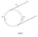
- the figure 2presents an exemplary device according to the known art for determining the incidence and the skidding of an aircraft from local measurements of incidence.
- This devicecomprises a first pallet 201 located on one side of the fuselage 101 and a second pallet 202 located on another side of the fuselage symmetrical to the first pallet with respect to the plane of symmetry of the aircraft.
- the first pallet 201measuring a first local angle of incidence ⁇ locG and the second pallet 202 a second angle of local incidence ⁇ locD .
- f and gare functions depending on the aerodynamic characteristics of the aircraft and taking into account the corrections related to the disturbances mentioned above.
- the figure 3presents the way in which the airspeed parameters are determined from the local measurements made.
- the conventional speed Vcis deduced from the difference ⁇ P between the stop pressure Pt and the local static pressure Ps.
- the number of Mach Mis determined from the ratio between, on the one hand, the difference ⁇ P between the stop pressure Pt and the local static pressure Ps and, on the other hand, the local static pressure Ps.
- the static temperature Tis determined from the impact temperature Ti and the number of mach M
- the number of mach M and the static temperature Tthen make it possible to calculate the modulus of the true air velocity vector V.
- the local static pressure Ps and the static temperature Tthen make it possible to calculate the density of the air e.
- the modulus of the true air speed vector, the angle of incidence and the upstream infinite skid angle of the aircraftmake it possible to define entirely the true air speed vector of the aircraft.
- a system for measuring the true airspeed of an aircraft using a laser anemometer focusing at a great distance from the fuselage (at least 100 m) and carrying out at least three measurements at three different points of the aircraftis already known. space.
- a system for measuring the true airspeed of an aircraft using a laser anemometer focusing at a great distance from the fuselage (at least 100 m) and carrying out at least three measurements at three different points of the aircraftis already known. space.
- such a systemhas the disadvantage of needing a powerful laser with a wide opening.
- the determination of three appropriate measurement pointscan be difficult.
- the document FR 2 938 924 A1discloses a system for determining the true air velocity vector comprising four laser anemometers, each provided with a single measurement channel for measuring a local component of the true airspeed and being distributed in different locations around the fuselage of the aircraft, each of the laser anemometers emitting laser radiation at a predetermined distance of a few meters or tens of meters beyond the aircraft.
- the document FR 2 891 409 A1discloses a laser anemometry system which has improved sensitivity enabling high altitude operation with a reduced energy incident optical signal and having a focus area being fifty centimeters apart.
- the inventionaims in particular to overcome the problems mentioned above by proposing a system for determining the air speed of a more reliable aircraft and easier to install on the fuselage of the aircraft.
- the inventionthus facilitates the implementation of measurements of anemometric parameters.
- the subject of the inventionis a system for determining the true air speed vector, defined by a module and by a direction, of an aircraft comprising a fuselage, said system comprising the features of claim 1.
- the solution of the inventionuses laser anemometers capable of measuring along a line of sight (using Doppler measurement) to determine incidence and slip.
- the laser anemometeroffers safety advantages (no risk of icing, dissimilarity compared to a conventional system, reliability, insensitivity to aerosols).
- the inventionmakes it possible not to use a sensitive and protruding pitot probe, probe and tube.
- This equipmentparticularly sensitive to frost, is replaced by more resistant and non-protuberant laser anemometers.
- the first and second of the six laser anemometersare located substantially in the horizontal plane of the aircraft and symmetrically with respect to the longitudinal axis of the aircraft.
- the third and fourth of the six laser anemometersare located substantially in the vertical plane of the aircraft and symmetrically with respect to the longitudinal axis of the aircraft.
- the axis in which the measurement is madeis an axis situated in a plane parallel to the plane tangent to the fuselage, said measurement axis forming an angle D with the axis lying in a plane parallel to the plane tangential to the fuselage and parallel to the plane. longitudinal axis of the fuselage.
- the angle D between the measurement axis and the axis located in a plane parallel to the plane tangential to the fuselage and parallel to the longitudinal axis of the fuselageis substantially equal to 45 degrees.
- the laser anemometersare fiberized, each of the laser anemometers being connected by an optical fiber to the same power source.
- the inventionmakes it possible to fully characterize the speed vector of the aircraft, that is to say, its modulus and its direction (using the incidence and the skid) from at least four measurements of local speed component.
- the figure 4shows an example of implementation of the measuring system according to the invention.
- the systemcomprises six anemometers 401, 402, 403, 404, 405, 406, lasers distributed around the fuselage 101 of the aircraft measuring a component of the true air speed and being distributed in different locations around the fuselage 101 of the aircraft .
- the systemalso includes means for calculating the true air speed of the aircraft from the six local component measurements of the true air speed.
- the fifth anemometer 405is located midway between the second and fourth and the sixth anemometer 406 located midway between the fourth and the first.
- the anemometersare then located under the fuselage of the aircraft and thus protected from the weather.
- This redundant configurationhas the advantage of being able to detect a failure of one of the laser anemometers.
- Anemometersare configured to perform local measurements.
- the lasersfocus at a distance close to the fuselage, less than 1 meter, and for example between 10 and 50 cm for a fuselage whose diameter is comprised in 4 meters and 8 meters. This allows the use of low power lasers that are less expensive and less bulky than lasers that can focus at greater distances.
- Each of the laser anemometershas only one measurement channel, ie it only measures a speed in one axis.
- the first 401 and second 402 of the six anemometersare located substantially in the horizontal plane of the aircraft and symmetrically with respect to the longitudinal axis 102 of the aircraft; the third 403 and the fourth 404 of the four anemometers are located substantially in the vertical plane of the aircraft and symmetrically with respect to the longitudinal axis 102 of the aircraft.
- This particular embodimentmakes it possible to facilitate calculations for determining the speed vector from the measurements.
- the axis in which the measurement is madeis an axis located in a plane 411 substantially parallel to the plane tangent to the fuselage. This axis forms an angle D with the axis 412 located in the plane 411 substantially parallel to the plane tangential to the fuselage and parallel to the longitudinal axis of the fuselage.
- the value of the angle Dis significantly greater than 0, so as not to be in the axis of movement of the aircraft
- Dcan be for example of the order of 45 °.
- the figure 5presents the way in which the airspeed parameters are determined from the local measurements made.
- the vector of the air velocity at infinity upstream Vis calculated from the components of true air velocity measured by the laser anemometers. However, these measurements are strongly disturbed by the presence of the fuselage. A correction is therefore necessary.
- a prior calibration in flight(in the development phase of the aircraft) is therefore necessary, after, a first theoretical estimate resulting from calculations of fluid mechanics on the fuselage portion considered.
- the means for calculating the true air speed of the aircraftimplement such a table to establish the true air speed from the six local component measurements of the true air speed.
- each local measurement Uiresulting from a laser anemometer, depends on the module of the upstream infinite speed V, the incidence and the skidding.
- the dynamic pressure ⁇ Pis directly deduced from the difference between the static pressure Ps and the stop pressure Pt measured.
- the dynamic pressurethen makes it possible to calculate the conventional speed Vc.
- the air velocity at infinity upstream V and the impact temperaturemake it possible to determine the number of mach M and the static temperature T.
- the density of the air eis established from the local static pressure Ps and the static temperature T.
- the laser anemometersare fibered.
- a fiber-optic anemometerthen uses a remote power source to which it is connected by an optical fiber. It is then possible to use a plurality of laser anemometers connected to the same power source.
- each of the laser anemometersbeing connected, by an optical fiber, to the same power source.
- This embodimenthas the advantage of being easier to implement and more economical.
Landscapes
- Physics & Mathematics (AREA)
- Engineering & Computer Science (AREA)
- Electromagnetism (AREA)
- General Physics & Mathematics (AREA)
- Computer Networks & Wireless Communication (AREA)
- Radar, Positioning & Navigation (AREA)
- Remote Sensing (AREA)
- Aviation & Aerospace Engineering (AREA)
- Multimedia (AREA)
- Indicating Or Recording The Presence, Absence, Or Direction Of Movement (AREA)
- Optical Radar Systems And Details Thereof (AREA)
Description
Translated fromFrenchL'invention se situe dans le domaine des mesures embarquées anémométriques des aéronefs à voilure fixe.The invention lies in the field of on-board airborne measurements of fixed-wing aircraft.
Les mesures embarquées anémométriques visent à déterminer notamment les valeurs suivantes situées à l'infini amont : la vitesse air vraie (ou TAS pour True Air Speed), l'incidence, le dérapage, la vitesse conventionnelle et la pression statique de l'aéronef ou l'altitude pression.The on-board airborne measurements are intended to determine in particular the following values located at infinity upstream: true air speed (or TAS for True Air Speed), the incidence, the skid, the conventional speed and the static pressure of the aircraft or pressure altitude.
On rappelle que :
- la vitesse air vraie V est la vitesse d'un aéronef par rapport à l'air non perturbé,
- l'incidence est l'angle α formé entre le vecteur vitesse V de l'aéronef et l'axe longitudinal,
- le dérapage est l'angle entre le vecteur vitesse V et le plan de symétrie (plan vertical) de l'aéronef,
- la pression statique Ps est une pression mesurée par exemple par une prise de pression statique,
- la pression d'arrêt (Pt) est la pression mesurée par un tube de Pitot, par exemple,
- la vitesse conventionnelle Vc est la vitesse utilisée pour déterminer la vitesse de décrochage de l'aéronef (c'est la vitesse qu'aurait l'aéronef, au niveau du sol, en conditions standards, avec la même mesure de pression Pt moins Ps), et
- l'altitude pression est l'altitude correspondant à la pression statique dans la table d'atmosphère standard définie par l'Organisation de l'Aéronautique Civile Internationale.
- the true air speed V is the speed of an aircraft relative to the undisturbed air,
- the incidence is the angle α formed between the speed vector V of the aircraft and the longitudinal axis,
- the skid is the angle between the velocity vector V and the plane of symmetry (vertical plane) of the aircraft,
- the static pressure Ps is a pressure measured for example by a static pressure tap,
- the stop pressure (Pt) is the pressure measured by a Pitot tube, for example,
- the conventional speed Vc is the speed used to determine the stalling speed of the aircraft (this is the speed that the aircraft would have, at ground level, in standard conditions, with the same pressure measurement Pt minus Ps) , and
- the pressure altitude is the altitude corresponding to the static pressure in the standard atmosphere table defined by the International Civil Aviation Organization.
Ces valeurs correspondent à l'infini amont de l'appareil. L'infini amont est une distance suffisamment grande (par exemple six diamètres de fuselage de l'aéronef) en amont de l'aéronef tel que le déplacement d'air induit par le déplacement dudit l'aéronef ne perturbe pas le champ aérodynamique.These values correspond to the upstream infinity of the device. The upstream infinity is a sufficiently large distance (for example six fuselage diameters of the aircraft) upstream of the aircraft such that the displacement of air induced by the movement of said aircraft does not disturb the aerodynamic field.
Les systèmes actuels déterminent ces valeurs à l'infini amont à l'aide de mesures locales de clinométrie et d'anémométrie. Ces mesures locales sont réalisées au voisinage du fuselage et sont donc soumises aux perturbations générées par celui-ci.Current systems determine these values at infinity upstream using local measurements of clinometry and anemometry. These local measurements are made in the vicinity of the fuselage and are therefore subject to the disturbances generated by it.
Les perturbations induites par l'aéronef peuvent être calculées pour corriger les mesures locales de manière adéquate. Pour établir ces corrections, il est nécessaire de procéder à un étalonnage préalable lors d'essais en vol réalisés par le constructeur.The disturbances induced by the aircraft can be calculated to correct the local measurements adequately. In order to establish these corrections, it is necessary to carry out a preliminary calibration during flight tests carried out by the manufacturer.
Les systèmes selon l'art connu pour déterminer l'anémométrie d'un aéronef comprennent :
- une sonde d'incidence placée à un endroit particulier (incidence locale insensible au dérapage) et mesurant une incidence locale αloc,
- éventuellement une sonde de dérapage mesurant un dérapage local βloc,
- un tube de Pitot mesurant une pression d'arrêt Pt, et
- une paire de prises de pression statiques gauche-droite placées à des endroits particuliers (où la pression statique moyenne G/D (gauche-droite) ne dépend pas du dérapage, et pour laquelle on effectue une moyenne pneumatique des pressions G/D, que l'on corrige par des lois de type « SSEC » (pour Static Source Error Correction), pour calculer la pression statique locale Ps, et
- une sonde pour mesurer une température d'impact Ti (ou TAT pour Total Air Temperature) qui est la température due à l'échauffement cinétique lors du déplacement de l'aéronef.
- an incidence probe placed at a particular location (local incidence insensitive to skidding) and measuring a local incidence αloc ,
- possibly a skid probe measuring a local skid βloc ,
- a pitot tube measuring a stop pressure Pt, and
- a pair of left-right static pressure taps placed at particular locations (where the mean static pressure G / D (left-right) does not depend on the skidding, and for which a pneumatic average of the G / D pressures is one corrects by laws of the type "SSEC" (for Static Source Error Correction), to calculate the local static pressure Ps, and
- a probe for measuring an impact temperature Ti (or TAT for Total Air Temperature) which is the temperature due to the kinetic heating during the displacement of the aircraft.
La
On rappelle que l'incidence locale αloc est un angle entre, d'une part, un vecteur d'une vitesse Vloc mesurée localement (c'est-à-dire aux abords du fuselage) dans le plan tangent 100 au fuselage 101 et, d'autre part, un vecteur u situé dans le plan tangent et parallèle à l'axe longitudinal de l'aéronef 102.It is recalled that the local incidence αloc is an angle between, on the one hand, a vector of a velocity Vloc measured locally (that is to say around the fuselage) in the
La sonde mesurant l'incidence locale αloc est par exemple une palette (c'est-à-dire une petite ailette mobile) s'alignant dans le lit du vent.The probe measuring the local incidence αloc is for example a pallet (that is to say a small mobile wing) aligning with the wind bed.
De façon alternative, l'incidence locale αloc peut aussi être déterminée indirectement en effectuant deux mesures :
- une mesure du vecteur vitesse u situé dans le plan tangent 100 et parallèle à l'axe longitudinal de l'aéronef 102, et
- une mesure d'un vecteur vitesse v situé dans le plan tangent 100 et orthogonal au vecteur vitesse u.
- a measurement of the velocity vector u located in the
tangent plane 100 and parallel to the longitudinal axis of theaircraft 102, and - a measurement of a velocity vector v located in the
tangent plane 100 and orthogonal to the velocity vector u.
L'incidence locale αloc est alors déterminée à partir de ces deux valeurs en appliquant la formule suivante : αloc = Tan-1 (v/u)The local incidence αloc is then determined from these two values by applying the following formula: αloc = Tan-1 (v / u)
Comme pour l'incidence locale, on peut mesurer le dérapage directement, à l'aide d'une palette s'alignant dans le lit du vent.As with local incidence, skidding can be measured directly, using a pallet that aligns with the wind bed.
On peut aussi déterminer le dérapage à partir du ratio de deux composantes mesurées.We can also determine the slip from the ratio of two measured components.
La
Ce dispositif comprend une première palette 201 située sur un coté du fuselage 101 et une deuxième palette 202 situé sur un autre coté du fuselage symétrique à la première palette par rapport au plan de symétrie de l'aéronef. La première palette 201 mesurant un premier angle d'incidence locale αlocG et la deuxième palette 202 un deuxième angle d'incidence locale αlocD. L'incidence α et le dérapage α à l'infini amont de l'aéronef peuvent alors être déterminés à l'aide des mesures locales précédentes en appliquant les relations suivantes:

Où f et g sont des fonctions dépendant des caractéristiques aérodynamiques de l'aéronef et prenant en compte les corrections liés aux perturbations évoquées précédemment.Where f and g are functions depending on the aerodynamic characteristics of the aircraft and taking into account the corrections related to the disturbances mentioned above.
La
La vitesse conventionnelle Vc est déduite de la différence ΔP entre la pression d'arrêt Pt et la pression statique locale Ps.The conventional speed Vc is deduced from the difference ΔP between the stop pressure Pt and the local static pressure Ps.
Le nombre de Mach M est déterminé à partir du ratio entre, d'une part, la différence ΔP entre la pression d'arrêt Pt et la pression statique locale Ps et, d'autre part, la pression statique locale Ps.The number of Mach M is determined from the ratio between, on the one hand, the difference ΔP between the stop pressure Pt and the local static pressure Ps and, on the other hand, the local static pressure Ps.
La température statique T est déterminée à partir de la température d'impact Ti et du nombre de mach MThe static temperature T is determined from the impact temperature Ti and the number of mach M
Le nombre de mach M et la température statique T permettent alors de calculer le module du vecteur vitesse air vrai V.The number of mach M and the static temperature T then make it possible to calculate the modulus of the true air velocity vector V.
La pression statique locale Ps et la température statique T permettent alors de calculer la masse volumique de l'air e.The local static pressure Ps and the static temperature T then make it possible to calculate the density of the air e.
Le module du vecteur vitesse air vraie, l'angle d'incidence et l'angle de dérapage à l'infini amont de l'aéronef permettent de définir entièrement le vecteur vitesse air vraie de l'aéronef.The modulus of the true air speed vector, the angle of incidence and the upstream infinite skid angle of the aircraft make it possible to define entirely the true air speed vector of the aircraft.
Ces systèmes ont pour inconvénients notamment d'avoir recours à des instruments de mesures, par exemple les palettes, fragiles car légères et particulièrement sensible au givrage.These systems have the particular disadvantages of using measuring instruments, for example pallets, fragile because light and particularly sensitive to icing.
Ces systèmes sont en outre complexes à installer car les instruments de mesures doivent en outre être placés à des points spécifiques du fuselage de l'aéronef pour minimiser les erreurs de mesures liées aux perturbations.These systems are also complex to install because the measuring instruments must also be placed at specific points of the fuselage of the aircraft to minimize measurement errors related to disturbances.
On connaît déjà un système de mesure de la vitesse air vraie d'un aéronef à l'aide d'un anémomètre laser focalisant à une grande distance du fuselage (au moins 100m) et réalisant au moins trois mesures en trois points différents de l'espace. Cependant un tel système a pour inconvénient de nécessité un laser puissant et avec une large ouverture. De plus, la détermination de trois points de mesure appropriés peut être difficile.A system for measuring the true airspeed of an aircraft using a laser anemometer focusing at a great distance from the fuselage (at least 100 m) and carrying out at least three measurements at three different points of the aircraft is already known. space. However, such a system has the disadvantage of needing a powerful laser with a wide opening. In addition, the determination of three appropriate measurement points can be difficult.
Le document
Le document
L'invention vise notamment à pallier les problèmes cités précédemment en proposant un système pour la détermination de la vitesse air d'un aéronef plus fiable et plus facile installer sur le fuselage de l'aéronef.The invention aims in particular to overcome the problems mentioned above by proposing a system for determining the air speed of a more reliable aircraft and easier to install on the fuselage of the aircraft.
L'invention facilite ainsi la mise en oeuvre des mesures de paramètres anémométriques.The invention thus facilitates the implementation of measurements of anemometric parameters.
A cet effet, l'invention a pour objet un système pour la détermination du vecteur vitesse air vraie, défini par un module et par une direction, d'un aéronef comportant un fuselage, ledit système comportant les caractéristiques de la revendication 1.For this purpose, the subject of the invention is a system for determining the true air speed vector, defined by a module and by a direction, of an aircraft comprising a fuselage, said system comprising the features of
La solution de l'invention utilise des anémomètres à laser capables de faire des mesures selon un axe de visée (grâce à la mesure selon l'effet Doppler) pour déterminer l'incidence et le dérapage.The solution of the invention uses laser anemometers capable of measuring along a line of sight (using Doppler measurement) to determine incidence and slip.
L'anémomètre à laser présente des avantages au niveau sécurité (pas de risque de givrage, de dissemblance par rapport à un système classique, fiabilité, insensibilité aux aérosols).The laser anemometer offers safety advantages (no risk of icing, dissimilarity compared to a conventional system, reliability, insensitivity to aerosols).
L'invention permet de ne pas utiliser de sonde d'incidence, de sonde et de tube Pitot fragiles et protubérants. Ces équipements, particulièrement sensibles au givre, sont remplacés par des anémomètres lasers plus résistants et non protubérants.The invention makes it possible not to use a sensitive and protruding pitot probe, probe and tube. This equipment, particularly sensitive to frost, is replaced by more resistant and non-protuberant laser anemometers.
Avantageusement, le premier et le deuxième des six anémomètres lasers sont situées sensiblement dans le plan horizontal de l'aéronef et de façon symétrique par rapport à l'axe longitudinal de l'aéronef.Advantageously, the first and second of the six laser anemometers are located substantially in the horizontal plane of the aircraft and symmetrically with respect to the longitudinal axis of the aircraft.
Avantageusement, le troisième et le quatrième des six anémomètres lasers sont situées sensiblement dans le plan vertical de l'aéronef et de façon symétrique par rapport à l'axe longitudinal de l'aéronef.Advantageously, the third and fourth of the six laser anemometers are located substantially in the vertical plane of the aircraft and symmetrically with respect to the longitudinal axis of the aircraft.
Avantageusement, l'axe selon lequel est effectué la mesure est un axe situé dans un plan parallèle au plan tangent au fuselage, ledit axe de mesure formant un angle D avec l'axe situé dans plan parallèle au plan tangent au fuselage et parallèle à l'axe longitudinal du fuselage.Advantageously, the axis in which the measurement is made is an axis situated in a plane parallel to the plane tangent to the fuselage, said measurement axis forming an angle D with the axis lying in a plane parallel to the plane tangential to the fuselage and parallel to the plane. longitudinal axis of the fuselage.
Avantageusement, l'angle D entre l'axe de mesure et l'axe situé dans plan parallèle au plan tangent au fuselage et parallèle à l'axe longitudinal du fuselage est sensiblement égal à 45 degrés.Advantageously, the angle D between the measurement axis and the axis located in a plane parallel to the plane tangential to the fuselage and parallel to the longitudinal axis of the fuselage is substantially equal to 45 degrees.
Avantageusement, les anémomètres lasers sont fibrés, chacun des anémomètres lasers étant relié, par une fibre optique, à une même source de puissance.Advantageously, the laser anemometers are fiberized, each of the laser anemometers being connected by an optical fiber to the same power source.
L'invention sera mieux comprise et d'autres avantages apparaîtront à la lecture de la description détaillée faite à titre d'exemple non limitatif et à l'aide des figures parmi lesquelles :
- La
figure 1 , déjà présentée, illustre une incidence locale aux abords d'un fuselage d'un aéronef. - La
figure 2 , déjà présentée, présente un exemple de dispositif selon l'art connu pour déterminer l'incidence et le dérapage d'un aéronef à partir de mesures locales d'incidence et de dérapage. - La
figure 3 , déjà présentée, présente la façon dont sont déterminés les paramètres anémométriques à partir des mesures locales effectuées. - La
figure 4 présente un exemple de mise en oeuvre du système de mesure selon l'invention. - La
figure 5 présente la façon dont sont déterminés les paramètres anémométriques à partir des mesures locales effectuées.
- The
figure 1 , already presented, illustrates a local impact around a fuselage of an aircraft. - The
figure 2 , already presented, presents an exemplary device according to the known art for determining the incidence and the skidding of an aircraft from local measurements of incidence and skidding. - The
figure 3 , already presented, presents the way in which the anemometric parameters are determined from the local measurements made. - The
figure 4 shows an example of implementation of the measuring system according to the invention. - The
figure 5 presents the way in which the airspeed parameters are determined from the local measurements made.
L'invention permet de caractériser entièrement le vecteur vitesse de l'aéronef, c'est-à-dire, son module et sa direction (à l'aide de l'incidence et du dérapage) à partir d'au moins quatre mesures de composante de vitesse locale.The invention makes it possible to fully characterize the speed vector of the aircraft, that is to say, its modulus and its direction (using the incidence and the skid) from at least four measurements of local speed component.
La
Le système comprend six anémomètres 401, 402, 403, 404, 405, 406, lasers répartis autour du fuselage 101 de l'aéronef mesurant une composante de la vitesse air vraie et étant répartis dans des localisations différentes autour du fuselage 101 de l'aéronef.The system comprises six
Le système comprend aussi des moyens pour le calcul de la vitesse air vraie de l'aéronef à partir des six mesures de composante locale de la vitesse air vraie.The system also includes means for calculating the true air speed of the aircraft from the six local component measurements of the true air speed.
Le cinquième anémomètre 405 est situé à mi-distance entre le deuxième et le quatrième et le sixième anémomètre 406 situé à mi-distance entre le quatrième et le premier.The
Les anémomètres étant alors situés sous le fuselage de l'aéronef et donc protégés des intempéries.The anemometers are then located under the fuselage of the aircraft and thus protected from the weather.
Le positionnement à mi distance des autres anémomètres permet de faciliter les calculs effectués sur les mesures.Positioning the other anemometers at a distance makes it easier to calculate the measurements.
Cette configuration redondante a pour avantage de pouvoir détecter une panne de l'un des anémomètres laser.This redundant configuration has the advantage of being able to detect a failure of one of the laser anemometers.
Les anémomètres sont configurés pour réaliser des mesures locales. Les lasers focalisent à une distance proche du fuselage, inférieure à 1 mètre, et par exemple comprise entre 10 et 50 cm pour un fuselage dont le diamètre est compris en 4 mètres et 8 mètres. Ceci permet d'utiliser des lasers à faible puissance qui sont moins coûteux et moins volumineux que des lasers pouvant focaliser à des distances plus importantes.Anemometers are configured to perform local measurements. The lasers focus at a distance close to the fuselage, less than 1 meter, and for example between 10 and 50 cm for a fuselage whose diameter is comprised in 4 meters and 8 meters. This allows the use of low power lasers that are less expensive and less bulky than lasers that can focus at greater distances.
Chacun des anémomètres laser ne présente qu'une unique voie de mesure, c'est-à-dire qu'il n'effectue une mesure de vitesse que selon un seul axe. Ainsi, à un instant donné, on obtient un jeu de six composantes locales de la vitesse air qui sont utilisées pour déterminer le module du vecteur vitesse air vraie, l'incidence et le dérapage.Each of the laser anemometers has only one measurement channel, ie it only measures a speed in one axis. Thus, at a given moment, we obtain a set of six local components of the air velocity which are used to determine the modulus of the true air velocity vector, the incidence and the skidding.
De façon avantageuse, le premier 401 et le deuxième 402 des six anémomètres sont situés sensiblement dans le plan horizontal de l'aéronef et de façon symétrique par rapport à l'axe longitudinal 102 de l'aéronef ; le troisième 403 et le quatrième 404 des quatre anémomètres sont situés sensiblement dans le plan vertical de l'aéronef et de façon symétrique par rapport à l'axe longitudinal 102 de l'aéronef.Advantageously, the first 401 and second 402 of the six anemometers are located substantially in the horizontal plane of the aircraft and symmetrically with respect to the
Ce mode de réalisation particulier permet de faciliter les calculs de détermination du vecteur vitesse à partir des mesures.This particular embodiment makes it possible to facilitate calculations for determining the speed vector from the measurements.
L'axe selon lequel est effectué la mesure est un axe situé dans un plan 411 sensiblement parallèle au plan tangent au fuselage. Cet axe forme un angle D avec l'axe 412 situé dans le plan 411 sensiblement parallèle au plan tangent au fuselage et parallèle à l'axe longitudinal du fuselage.The axis in which the measurement is made is an axis located in a
La valeur de l'angle D est significativement supérieure à 0, afin de ne pas être dans l'axe de déplacement de l'avionThe value of the angle D is significantly greater than 0, so as not to be in the axis of movement of the aircraft
D peut être par exemple de l'ordre de 45°.D can be for example of the order of 45 °.
L'important est de faire une mesure à quelques dizaines de centimètres de l'émetteur (Par émetteur, on entend la lentille d'émission du faisceau laser), dans un plan quasi tangent (en étant situé a quelques centimètres de la paroi pour être situé en dehors de la couche limite qui se développe sur le fuselage de l'aéronef). Ceci est valable pour les valeurs de diamètre de fuselage d'un avion de transport, c'est à dire de 2 à 8 m de diamètre environs.The important thing is to make a measurement a few tens of centimeters from the transmitter (By transmitter, we mean the emission lens of the laser beam), in an almost tangent plane (being located a few centimeters from the wall to be located outside the boundary layer that develops on the fuselage of the aircraft). This is valid for the fuselage diameter values of a transport aircraft, ie about 2 to 8 m in diameter.
La
Le vecteur de la vitesse air vraie à l'infini amont V est calculée à partir des composantes de vitesse air vrai mesurées par les anémomètres laser. Cependant, ces mesures sont fortement perturbées par la présence du fuselage. Une correction est donc nécessaire.The vector of the air velocity at infinity upstream V is calculated from the components of true air velocity measured by the laser anemometers. However, these measurements are strongly disturbed by the presence of the fuselage. A correction is therefore necessary.
Un étalonnage préalable en vol (en phase développement de l'aéronef) est donc nécessaire, après, une première estimation théorique résultant de calculs de mécanique des fluides sur la portion de fuselage considérée.A prior calibration in flight (in the development phase of the aircraft) is therefore necessary, after, a first theoretical estimate resulting from calculations of fluid mechanics on the fuselage portion considered.
Il est important d'explorer l'ensemble du domaine de vol de l'aéronef, en incidence, dérapage, vitesse et altitude, et d'enregistrer les différentes mesures, avec une référence de vitesse qui est déterminée, par exemple par un anémomètre laser focalisant à distance moyenne (une centaine de mètres), et une référence de pression statique qui peut être classiquement un cône tracté (permettant d'éviter les perturbations dues au fuselage) ou une méthode indirecte à base de mesure d'altitude provenant de radio navigation (GPS par exemple), le vent étant estimé par des lâchers de ballons-sondes.It is important to explore the entire flight envelope of the aircraft, in incidence, skid, speed and altitude, and record the different measurements, with a speed reference that is determined, for example by a laser anemometer focusing at medium distance (a hundred meters), and a static pressure reference that can be classically a towed cone (to avoid disturbances due to the fuselage) or an indirect method based on altitude measurement from radio navigation (GPS for example), the wind being estimated by the release of balloons-probes.
On peut donc alors enregistrer l'ensemble des paramètres (4 ou 6 vitesses locales, pressions statiques, température) en fonction des paramètres de référence (incidence, dérapage, nombre de Mach, vitesse conventionnelle, et altitude pression) et ainsi obtenir un tableau de correspondance permettant de fournir les coefficients d'étalonnage du système anémométrique.We can then record all the parameters (4 or 6 local velocities, static pressures, temperature) according to the reference parameters (incidence, skid, Mach number, conventional speed, and altitude pressure) and thus obtain a table of correspondence to provide the calibration coefficients of the airspeed system.
Les moyens pour le calcul de la vitesse air vraie de l'aéronef mettent en oeuvre un tel tableau pour établir la vitesse air vraie à partir des six mesures de composante locales de la vitesse air vraie.The means for calculating the true air speed of the aircraft implement such a table to establish the true air speed from the six local component measurements of the true air speed.
En tout point exploré du domaine de vol (altitude, nombre de Mach, incidence et dérapage), on enregistre les mesures locales et la mesure de référence (c'est-à-dire le vecteur vitesse air vraie définie par son module un angle d'incidence et un angle de dérapage). Chaque mesure locale Ui, issue d'un anémomètre laser, dépend du module de la vitesse infini amont V, de l'incidence et du dérapage.At any point explored in the flight domain (altitude, Mach number, incidence and skid), the local measurements and the reference measurement (ie the true airspeed vector defined by its modulus, an angle of incidence and a slip angle). Each local measurement Ui, resulting from a laser anemometer, depends on the module of the upstream infinite speed V, the incidence and the skidding.
On détermine ensuite à l'aide de ces mesures des courbes de mesure locale Ui fonction, par exemple, d'un angle d'incidence et pour des modules de vitesses constants et des dérapages constants.Using these measurements, local measurement curves Ui are determined, for example, by an angle of incidence and for constant speed moduli and constant slippage.
Des quatre réseaux de courbes Ui, (ix1,2,3,4) on déduit alors les valeurs attendues du vecteur vitesse air (module et incidence et dérapage). Il n'y a pas à proprement parler de correction, mais modélisation entre les mesures locales et le vecteur vitesse air.From the four networks of curves Ui, (ix1,2,3,4) the expected values of the air velocity vector (modulus and incidence and slip) are then deduced. There is no actual correction, but modeling between local measurements and air velocity vector.
L'ajout des autres deux valeurs permet soit de lever des ambigüités si les courbes précédentes ne permettent de trouver une seule solution, soit de sécuriser l'information par détection de mesures erronées.The addition of the other two values makes it possible to remove ambiguities if the preceding curves do not make it possible to find a single solution, or to secure the information by detecting erroneous measurements.
La pression dynamique ΔP est directement déduite de l'écart entre la pression statique Ps et la pression d'arrêt Pt mesurées.The dynamic pressure ΔP is directly deduced from the difference between the static pressure Ps and the stop pressure Pt measured.
La pression dynamique permet alors de calculer la vitesse conventionnelle Vc.The dynamic pressure then makes it possible to calculate the conventional speed Vc.
La vitesse air vraie à l'infini amont V et la température d'impact permettent de déterminer le nombre de mach M et la température statique T.The air velocity at infinity upstream V and the impact temperature make it possible to determine the number of mach M and the static temperature T.
Comme précédemment, la masse volumique de l'air e est établie à partir de la pression statique locale Ps et la température statique T.As previously, the density of the air e is established from the local static pressure Ps and the static temperature T.
Selon un mode de réalisation préféré de l'invention, les anémomètres lasers sont fibrés. Un anémomètre fibré utilise alors une source de puissance distante à laquelle il est relié par une fibre optique. Il est alors possible d'utiliser une pluralité d'anémomètres lasers reliés à la même source de puissance.According to a preferred embodiment of the invention, the laser anemometers are fibered. A fiber-optic anemometer then uses a remote power source to which it is connected by an optical fiber. It is then possible to use a plurality of laser anemometers connected to the same power source.
Ainsi, chacun des anémomètres lasers étant relié, par une fibre optique, à une même source de puissance.Thus, each of the laser anemometers being connected, by an optical fiber, to the same power source.
Ce mode de réalisation a pour avantage d'être plus facile à mettre en oeuvre et plus économique.This embodiment has the advantage of being easier to implement and more economical.
Claims (6)
- A system for determining the true air speed vector, defined by a modulus and by a direction, of an aircraft comprising a fuselage (101), said system comprising:a first, second, third, fourth, fifth and sixth laser anemometer (401, 402, 403, 404, 405 and 406) each provided with a single measurement channel for measuring a local component of the true air speed and being distributed over various locations around said fuselage (101) of the aircraft,said system beingcharacterised in that:said laser anemometers are configured so as to carry out local measurements with a focusing point at a distance of less than one metre;said fifth laser anemometer (405) is located halfway between said fourth (404) and said second (402) laser anemometer andsaid sixth laser anemometer (406) is located halfway between said fourth (404) and said first (404) laser anemometer,said system further comprising means for calculating the modulus and the direction of the vector of the true air speed of the aircraft on the basis of the six local component measurements of the true air speed, said means implementing a table of correspondence allowing a correlation to be made between the local measurements and the true air speed vector and thus taking into account the disruptions associated with the presence of the fuselage.
- The system according to claim 1, wherein the first (401) and the second (402) laser anemometers of the six laser anemometers are substantially located in the horizontal plane of the aircraft and are symmetrically located relative to the longitudinal axis (102) of the aircraft.
- The system according to claim 1 or 2, wherein the third (403) and the fourth (404) laser anemometers of the six laser anemometers are substantially located in the vertical plane of the aircraft and are symmetrically located relative to the longitudinal axis (102) of the aircraft.
- The system according to any one of the preceding claims, wherein the axis along which the measurement is carried out is an axis located in a plane parallel to the tangential plane of the fuselage, said measurement axis forming an angle D with the axis located in the plane parallel to the plane tangent to the fuselage and parallel to the longitudinal axis of the fuselage.
- The system according to claim 4, wherein the angle D between the axis of measurement and the axis located in the plane parallel to the tangential plane of the fuselage and parallel to the longitudinal axis of the fuselage is substantially equal to 45 degrees.
- The system according to any one of the preceding claims, wherein said laser anemometers are fibre based, with each of said laser anemometers being connected by an optical fibre to the same power source.
Applications Claiming Priority (1)
| Application Number | Priority Date | Filing Date | Title |
|---|---|---|---|
| FR1003994AFR2965928B1 (en) | 2010-10-08 | 2010-10-08 | SYSTEM FOR DETERMINING THE AIR SPEED OF AN AIRCRAFT |
Publications (2)
| Publication Number | Publication Date |
|---|---|
| EP2439541A1 EP2439541A1 (en) | 2012-04-11 |
| EP2439541B1true EP2439541B1 (en) | 2014-02-12 |
Family
ID=43982176
Family Applications (1)
| Application Number | Title | Priority Date | Filing Date |
|---|---|---|---|
| EP11184262.1AActiveEP2439541B1 (en) | 2010-10-08 | 2011-10-07 | System for determining the air speed of an aircraft |
Country Status (4)
| Country | Link |
|---|---|
| US (1) | US8718971B2 (en) |
| EP (1) | EP2439541B1 (en) |
| CA (1) | CA2754397A1 (en) |
| FR (1) | FR2965928B1 (en) |
Cited By (1)
| Publication number | Priority date | Publication date | Assignee | Title |
|---|---|---|---|---|
| US11815608B2 (en) | 2020-07-28 | 2023-11-14 | Honeywell International Inc. | Vector air data dynamic constraining and self-checking systems and methods |
Families Citing this family (12)
| Publication number | Priority date | Publication date | Assignee | Title |
|---|---|---|---|---|
| CN102707092B (en)* | 2012-06-19 | 2014-01-08 | 北京航空航天大学 | A single-beam laser velocimeter calibration method based on an angular rate platform |
| FR3000561B1 (en)* | 2012-12-28 | 2016-04-29 | Thales Sa | METHOD OF DETERMINING THE SPEED IN RELATION TO THE SURROUNDING AIR OF A ROTARY TURNING AIRCRAFT |
| CN104596515B (en)* | 2014-10-13 | 2017-06-06 | 北京航空航天大学 | A kind of Hardware In The Loop Simulation Method of inertial navigation/laser velocimeter integrated navigation |
| US10775504B2 (en)* | 2016-09-29 | 2020-09-15 | Honeywell International Inc. | Laser air data sensor mounting and operation for eye safety |
| US10598789B2 (en)* | 2016-09-29 | 2020-03-24 | Honeywell International Inc. | Mounting a laser transceiver to an aircraft |
| CN109850171B (en)* | 2017-11-28 | 2023-09-29 | 天津天航智远科技有限公司 | Airspeed measurement and safety switch integrated device for small unmanned aerial vehicle |
| US10578717B2 (en) | 2018-01-31 | 2020-03-03 | Honeywell International Inc. | Dimmable glass for eye safety for LiDAR technology |
| FR3093567B1 (en)* | 2019-03-07 | 2021-02-26 | Thales Sa | Aeronautical anemometric measurement system including low power lidar |
| FR3102856B1 (en) | 2019-11-05 | 2021-10-01 | Airbus Helicopters | Method and device for estimating the air speed of a rotorcraft by analyzing its rotor. |
| US12112648B2 (en)* | 2021-02-24 | 2024-10-08 | Honeywell International Inc. | Determining vehicle operating state by particle detection |
| FR3123723B1 (en)* | 2021-06-07 | 2023-04-21 | Thales Sa | Pressure measurement probe including a pressure sensor board |
| CN113533784B (en)* | 2021-09-07 | 2022-01-25 | 成都飞机工业(集团)有限责任公司 | GPS (global positioning system) round-trip non-constant-speed flat flight airspeed calibration method |
Citations (1)
| Publication number | Priority date | Publication date | Assignee | Title |
|---|---|---|---|---|
| FR2891409A1 (en)* | 2005-09-23 | 2007-03-30 | Thales Sa | LASER ANEMOMETRY DEVICE WITH IMPROVED EYE SAFETY |
Family Cites Families (3)
| Publication number | Priority date | Publication date | Assignee | Title |
|---|---|---|---|---|
| FR2725033B1 (en)* | 1994-09-22 | 1997-01-03 | Sextant Avionique | METHOD AND SYSTEM FOR DETERMINING ANEMOBAROCLINOMETRIC PARAMETERS ON BOARD AN AIRCRAFT |
| FR2922314B1 (en)* | 2007-10-16 | 2010-02-26 | Thales Sa | OPTICAL DEVICE FOR MEASURING ANEMOMETRIC PARAMETERS |
| FR2938924B1 (en) | 2008-11-24 | 2011-02-11 | Airbus France | METHOD AND DEVICE FOR DETERMINING ANEMOMETRIC PARAMETERS OF AN AIRCRAFT |
- 2010
- 2010-10-08FRFR1003994Apatent/FR2965928B1/ennot_activeExpired - Fee Related
- 2011
- 2011-10-07USUS13/269,128patent/US8718971B2/enactiveActive
- 2011-10-07EPEP11184262.1Apatent/EP2439541B1/enactiveActive
- 2011-10-07CACA2754397Apatent/CA2754397A1/ennot_activeAbandoned
Patent Citations (1)
| Publication number | Priority date | Publication date | Assignee | Title |
|---|---|---|---|---|
| FR2891409A1 (en)* | 2005-09-23 | 2007-03-30 | Thales Sa | LASER ANEMOMETRY DEVICE WITH IMPROVED EYE SAFETY |
Cited By (1)
| Publication number | Priority date | Publication date | Assignee | Title |
|---|---|---|---|---|
| US11815608B2 (en) | 2020-07-28 | 2023-11-14 | Honeywell International Inc. | Vector air data dynamic constraining and self-checking systems and methods |
Also Published As
| Publication number | Publication date |
|---|---|
| FR2965928A1 (en) | 2012-04-13 |
| CA2754397A1 (en) | 2012-04-08 |
| US8718971B2 (en) | 2014-05-06 |
| US20120089362A1 (en) | 2012-04-12 |
| EP2439541A1 (en) | 2012-04-11 |
| FR2965928B1 (en) | 2013-05-31 |
Similar Documents
| Publication | Publication Date | Title |
|---|---|---|
| EP2439541B1 (en) | System for determining the air speed of an aircraft | |
| CN108717195B (en) | Coherent Doppler wind lidar system and control method thereof | |
| EP2202524B1 (en) | Aerodynamic probe and helicopter equipped with the probe | |
| CN101833089B (en) | Doppler anemometry laser radar sensitivity calibrating system and method | |
| CN102508222B (en) | Middle and upper atmospheric wind field retrieval method | |
| CN101718799A (en) | Method and arrangement to determine a wind-speed | |
| FR3035209A1 (en) | MULTIFUNCTION PROBE FOR PRIMARY REFERENCES FOR AIRCRAFT, MEASUREMENT SYSTEM, AIRCRAFT AND METHOD FOR OBTAINING PHYSICAL SIZES | |
| EP3754341B1 (en) | Method for determining the vertical profile of the wind speed upstream of a wind turbine provided with a laser remote detection sensor | |
| EP2425262B1 (en) | Method and system for detecting and determining atmospheric abnormalities from afar | |
| EP2202525A1 (en) | Aerodynamic probe to measure air flow along a wall | |
| EP2977769B1 (en) | Method and device for estimating the mach number of an aircraft | |
| Mansour et al. | Seven-sensor fast-response probe for full-scale wind turbine flowfield measurements | |
| EP3049762A1 (en) | Method of calculating the surface speed of at least one ship and method for deduction of each vector derived at any point of the trajectory of said ship | |
| EP2583110A1 (en) | Method for locating a partial discharge transmission area and associated device | |
| FR3031811A1 (en) | METHOD AND DEVICE FOR DETERMINING THE WIND SPEED TO BE TAKEN INTO ACCOUNT IN ORDER TO OPTIMIZE THE MASS AT THE TAKE-OFF OF AN AIRCRAFT | |
| FR2694634A1 (en) | Incidence probe. | |
| FR2915584A1 (en) | METHOD OF DETECTION OF ATMOSPHERIC TURBULENCE BY AN ELECTROMAGNETIC SENSOR ONBOARD, IN PARTICULAR ABOARD AN AIRCRAFT. | |
| EP2196809B1 (en) | Bi-axial laser anemometric probe | |
| FR2938924A1 (en) | METHOD AND DEVICE FOR DETERMINING ANEMOMETRIC PARAMETERS OF AN AIRCRAFT | |
| FR3000561A1 (en) | METHOD FOR DETERMINING THE SPEED IN RELATION TO THE SURROUNDING AIR OF A ROTARY TURNING AIRCRAFT | |
| EP2333564A1 (en) | Power-assisted bistatic pressure sensor | |
| EP2876459A1 (en) | Device and method for determining the presence of damage or dirt on a laser Doppler anemometry probe window | |
| EP3100057B1 (en) | Device for measuring the travelling speed of a fluid in relation to an object | |
| CN110850393B (en) | Laser radar data verification method | |
| FR3067468B1 (en) | STATIC PRESSURE MEASURING PROBE SYSTEM AND METHOD THEREOF |
Legal Events
| Date | Code | Title | Description |
|---|---|---|---|
| AK | Designated contracting states | Kind code of ref document:A1 Designated state(s):AL AT BE BG CH CY CZ DE DK EE ES FI FR GB GR HR HU IE IS IT LI LT LU LV MC MK MT NL NO PL PT RO RS SE SI SK SM TR | |
| AX | Request for extension of the european patent | Extension state:BA ME | |
| PUAI | Public reference made under article 153(3) epc to a published international application that has entered the european phase | Free format text:ORIGINAL CODE: 0009012 | |
| 17P | Request for examination filed | Effective date:20121009 | |
| 17Q | First examination report despatched | Effective date:20121109 | |
| REG | Reference to a national code | Ref country code:DE Ref legal event code:R079 Ref document number:602011004907 Country of ref document:DE Free format text:PREVIOUS MAIN CLASS: G01P0005260000 Ipc:G01S0017950000 | |
| RIC1 | Information provided on ipc code assigned before grant | Ipc:G01S 17/95 20060101AFI20130703BHEP Ipc:G01P 5/26 20060101ALI20130703BHEP Ipc:G01S 17/58 20060101ALI20130703BHEP Ipc:G01P 13/02 20060101ALI20130703BHEP Ipc:G01S 17/87 20060101ALI20130703BHEP | |
| GRAP | Despatch of communication of intention to grant a patent | Free format text:ORIGINAL CODE: EPIDOSNIGR1 | |
| INTG | Intention to grant announced | Effective date:20130819 | |
| GRAS | Grant fee paid | Free format text:ORIGINAL CODE: EPIDOSNIGR3 | |
| GRAA | (expected) grant | Free format text:ORIGINAL CODE: 0009210 | |
| AK | Designated contracting states | Kind code of ref document:B1 Designated state(s):AL AT BE BG CH CY CZ DE DK EE ES FI FR GB GR HR HU IE IS IT LI LT LU LV MC MK MT NL NO PL PT RO RS SE SI SK SM TR | |
| REG | Reference to a national code | Ref country code:GB Ref legal event code:FG4D Free format text:NOT ENGLISH | |
| REG | Reference to a national code | Ref country code:CH Ref legal event code:EP | |
| REG | Reference to a national code | Ref country code:AT Ref legal event code:REF Ref document number:652376 Country of ref document:AT Kind code of ref document:T Effective date:20140215 | |
| REG | Reference to a national code | Ref country code:IE Ref legal event code:FG4D Free format text:LANGUAGE OF EP DOCUMENT: FRENCH | |
| REG | Reference to a national code | Ref country code:DE Ref legal event code:R096 Ref document number:602011004907 Country of ref document:DE Effective date:20140327 | |
| REG | Reference to a national code | Ref country code:NL Ref legal event code:VDEP Effective date:20140212 | |
| REG | Reference to a national code | Ref country code:AT Ref legal event code:MK05 Ref document number:652376 Country of ref document:AT Kind code of ref document:T Effective date:20140212 | |
| REG | Reference to a national code | Ref country code:LT Ref legal event code:MG4D | |
| PG25 | Lapsed in a contracting state [announced via postgrant information from national office to epo] | Ref country code:LT Free format text:LAPSE BECAUSE OF FAILURE TO SUBMIT A TRANSLATION OF THE DESCRIPTION OR TO PAY THE FEE WITHIN THE PRESCRIBED TIME-LIMIT Effective date:20140212 Ref country code:IS Free format text:LAPSE BECAUSE OF FAILURE TO SUBMIT A TRANSLATION OF THE DESCRIPTION OR TO PAY THE FEE WITHIN THE PRESCRIBED TIME-LIMIT Effective date:20140612 Ref country code:NO Free format text:LAPSE BECAUSE OF FAILURE TO SUBMIT A TRANSLATION OF THE DESCRIPTION OR TO PAY THE FEE WITHIN THE PRESCRIBED TIME-LIMIT Effective date:20140512 | |
| PG25 | Lapsed in a contracting state [announced via postgrant information from national office to epo] | Ref country code:ES Free format text:LAPSE BECAUSE OF FAILURE TO SUBMIT A TRANSLATION OF THE DESCRIPTION OR TO PAY THE FEE WITHIN THE PRESCRIBED TIME-LIMIT Effective date:20140212 Ref country code:PT Free format text:LAPSE BECAUSE OF FAILURE TO SUBMIT A TRANSLATION OF THE DESCRIPTION OR TO PAY THE FEE WITHIN THE PRESCRIBED TIME-LIMIT Effective date:20140612 Ref country code:CY Free format text:LAPSE BECAUSE OF FAILURE TO SUBMIT A TRANSLATION OF THE DESCRIPTION OR TO PAY THE FEE WITHIN THE PRESCRIBED TIME-LIMIT Effective date:20140212 Ref country code:FI Free format text:LAPSE BECAUSE OF FAILURE TO SUBMIT A TRANSLATION OF THE DESCRIPTION OR TO PAY THE FEE WITHIN THE PRESCRIBED TIME-LIMIT Effective date:20140212 Ref country code:SE Free format text:LAPSE BECAUSE OF FAILURE TO SUBMIT A TRANSLATION OF THE DESCRIPTION OR TO PAY THE FEE WITHIN THE PRESCRIBED TIME-LIMIT Effective date:20140212 Ref country code:NL Free format text:LAPSE BECAUSE OF FAILURE TO SUBMIT A TRANSLATION OF THE DESCRIPTION OR TO PAY THE FEE WITHIN THE PRESCRIBED TIME-LIMIT Effective date:20140212 Ref country code:AT Free format text:LAPSE BECAUSE OF FAILURE TO SUBMIT A TRANSLATION OF THE DESCRIPTION OR TO PAY THE FEE WITHIN THE PRESCRIBED TIME-LIMIT Effective date:20140212 | |
| PG25 | Lapsed in a contracting state [announced via postgrant information from national office to epo] | Ref country code:RS Free format text:LAPSE BECAUSE OF FAILURE TO SUBMIT A TRANSLATION OF THE DESCRIPTION OR TO PAY THE FEE WITHIN THE PRESCRIBED TIME-LIMIT Effective date:20140212 Ref country code:HR Free format text:LAPSE BECAUSE OF FAILURE TO SUBMIT A TRANSLATION OF THE DESCRIPTION OR TO PAY THE FEE WITHIN THE PRESCRIBED TIME-LIMIT Effective date:20140212 Ref country code:LV Free format text:LAPSE BECAUSE OF FAILURE TO SUBMIT A TRANSLATION OF THE DESCRIPTION OR TO PAY THE FEE WITHIN THE PRESCRIBED TIME-LIMIT Effective date:20140212 | |
| PG25 | Lapsed in a contracting state [announced via postgrant information from national office to epo] | Ref country code:EE Free format text:LAPSE BECAUSE OF FAILURE TO SUBMIT A TRANSLATION OF THE DESCRIPTION OR TO PAY THE FEE WITHIN THE PRESCRIBED TIME-LIMIT Effective date:20140212 Ref country code:DK Free format text:LAPSE BECAUSE OF FAILURE TO SUBMIT A TRANSLATION OF THE DESCRIPTION OR TO PAY THE FEE WITHIN THE PRESCRIBED TIME-LIMIT Effective date:20140212 Ref country code:CZ Free format text:LAPSE BECAUSE OF FAILURE TO SUBMIT A TRANSLATION OF THE DESCRIPTION OR TO PAY THE FEE WITHIN THE PRESCRIBED TIME-LIMIT Effective date:20140212 Ref country code:RO Free format text:LAPSE BECAUSE OF FAILURE TO SUBMIT A TRANSLATION OF THE DESCRIPTION OR TO PAY THE FEE WITHIN THE PRESCRIBED TIME-LIMIT Effective date:20140212 | |
| REG | Reference to a national code | Ref country code:DE Ref legal event code:R097 Ref document number:602011004907 Country of ref document:DE | |
| PG25 | Lapsed in a contracting state [announced via postgrant information from national office to epo] | Ref country code:SK Free format text:LAPSE BECAUSE OF FAILURE TO SUBMIT A TRANSLATION OF THE DESCRIPTION OR TO PAY THE FEE WITHIN THE PRESCRIBED TIME-LIMIT Effective date:20140212 Ref country code:PL Free format text:LAPSE BECAUSE OF FAILURE TO SUBMIT A TRANSLATION OF THE DESCRIPTION OR TO PAY THE FEE WITHIN THE PRESCRIBED TIME-LIMIT Effective date:20140212 | |
| PLBE | No opposition filed within time limit | Free format text:ORIGINAL CODE: 0009261 | |
| STAA | Information on the status of an ep patent application or granted ep patent | Free format text:STATUS: NO OPPOSITION FILED WITHIN TIME LIMIT | |
| 26N | No opposition filed | Effective date:20141113 | |
| REG | Reference to a national code | Ref country code:DE Ref legal event code:R097 Ref document number:602011004907 Country of ref document:DE Effective date:20141113 | |
| PG25 | Lapsed in a contracting state [announced via postgrant information from national office to epo] | Ref country code:IT Free format text:LAPSE BECAUSE OF FAILURE TO SUBMIT A TRANSLATION OF THE DESCRIPTION OR TO PAY THE FEE WITHIN THE PRESCRIBED TIME-LIMIT Effective date:20140212 | |
| PG25 | Lapsed in a contracting state [announced via postgrant information from national office to epo] | Ref country code:SI Free format text:LAPSE BECAUSE OF FAILURE TO SUBMIT A TRANSLATION OF THE DESCRIPTION OR TO PAY THE FEE WITHIN THE PRESCRIBED TIME-LIMIT Effective date:20140212 Ref country code:LU Free format text:LAPSE BECAUSE OF FAILURE TO SUBMIT A TRANSLATION OF THE DESCRIPTION OR TO PAY THE FEE WITHIN THE PRESCRIBED TIME-LIMIT Effective date:20141007 Ref country code:MC Free format text:LAPSE BECAUSE OF FAILURE TO SUBMIT A TRANSLATION OF THE DESCRIPTION OR TO PAY THE FEE WITHIN THE PRESCRIBED TIME-LIMIT Effective date:20140212 | |
| REG | Reference to a national code | Ref country code:CH Ref legal event code:PL | |
| PG25 | Lapsed in a contracting state [announced via postgrant information from national office to epo] | Ref country code:BE Free format text:LAPSE BECAUSE OF NON-PAYMENT OF DUE FEES Effective date:20141031 | |
| REG | Reference to a national code | Ref country code:IE Ref legal event code:MM4A | |
| PG25 | Lapsed in a contracting state [announced via postgrant information from national office to epo] | Ref country code:CH Free format text:LAPSE BECAUSE OF NON-PAYMENT OF DUE FEES Effective date:20141031 Ref country code:LI Free format text:LAPSE BECAUSE OF NON-PAYMENT OF DUE FEES Effective date:20141031 | |
| PG25 | Lapsed in a contracting state [announced via postgrant information from national office to epo] | Ref country code:IE Free format text:LAPSE BECAUSE OF NON-PAYMENT OF DUE FEES Effective date:20141007 | |
| PG25 | Lapsed in a contracting state [announced via postgrant information from national office to epo] | Ref country code:SM Free format text:LAPSE BECAUSE OF FAILURE TO SUBMIT A TRANSLATION OF THE DESCRIPTION OR TO PAY THE FEE WITHIN THE PRESCRIBED TIME-LIMIT Effective date:20140212 | |
| PG25 | Lapsed in a contracting state [announced via postgrant information from national office to epo] | Ref country code:GR Free format text:LAPSE BECAUSE OF FAILURE TO SUBMIT A TRANSLATION OF THE DESCRIPTION OR TO PAY THE FEE WITHIN THE PRESCRIBED TIME-LIMIT Effective date:20140513 Ref country code:BG Free format text:LAPSE BECAUSE OF FAILURE TO SUBMIT A TRANSLATION OF THE DESCRIPTION OR TO PAY THE FEE WITHIN THE PRESCRIBED TIME-LIMIT Effective date:20140212 | |
| PG25 | Lapsed in a contracting state [announced via postgrant information from national office to epo] | Ref country code:TR Free format text:LAPSE BECAUSE OF FAILURE TO SUBMIT A TRANSLATION OF THE DESCRIPTION OR TO PAY THE FEE WITHIN THE PRESCRIBED TIME-LIMIT Effective date:20140212 Ref country code:HU Free format text:LAPSE BECAUSE OF FAILURE TO SUBMIT A TRANSLATION OF THE DESCRIPTION OR TO PAY THE FEE WITHIN THE PRESCRIBED TIME-LIMIT; INVALID AB INITIO Effective date:20111007 Ref country code:MT Free format text:LAPSE BECAUSE OF FAILURE TO SUBMIT A TRANSLATION OF THE DESCRIPTION OR TO PAY THE FEE WITHIN THE PRESCRIBED TIME-LIMIT Effective date:20140212 | |
| REG | Reference to a national code | Ref country code:FR Ref legal event code:PLFP Year of fee payment:6 | |
| REG | Reference to a national code | Ref country code:FR Ref legal event code:PLFP Year of fee payment:7 | |
| PGFP | Annual fee paid to national office [announced via postgrant information from national office to epo] | Ref country code:GB Payment date:20170929 Year of fee payment:7 | |
| PGFP | Annual fee paid to national office [announced via postgrant information from national office to epo] | Ref country code:DE Payment date:20171004 Year of fee payment:7 | |
| PG25 | Lapsed in a contracting state [announced via postgrant information from national office to epo] | Ref country code:MK Free format text:LAPSE BECAUSE OF FAILURE TO SUBMIT A TRANSLATION OF THE DESCRIPTION OR TO PAY THE FEE WITHIN THE PRESCRIBED TIME-LIMIT Effective date:20140212 | |
| REG | Reference to a national code | Ref country code:FR Ref legal event code:PLFP Year of fee payment:8 | |
| PG25 | Lapsed in a contracting state [announced via postgrant information from national office to epo] | Ref country code:AL Free format text:LAPSE BECAUSE OF FAILURE TO SUBMIT A TRANSLATION OF THE DESCRIPTION OR TO PAY THE FEE WITHIN THE PRESCRIBED TIME-LIMIT Effective date:20140212 | |
| REG | Reference to a national code | Ref country code:DE Ref legal event code:R119 Ref document number:602011004907 Country of ref document:DE | |
| GBPC | Gb: european patent ceased through non-payment of renewal fee | Effective date:20181007 | |
| PG25 | Lapsed in a contracting state [announced via postgrant information from national office to epo] | Ref country code:DE Free format text:LAPSE BECAUSE OF NON-PAYMENT OF DUE FEES Effective date:20190501 | |
| PG25 | Lapsed in a contracting state [announced via postgrant information from national office to epo] | Ref country code:GB Free format text:LAPSE BECAUSE OF NON-PAYMENT OF DUE FEES Effective date:20181007 | |
| P01 | Opt-out of the competence of the unified patent court (upc) registered | Effective date:20230427 | |
| PGFP | Annual fee paid to national office [announced via postgrant information from national office to epo] | Ref country code:FR Payment date:20240923 Year of fee payment:14 |