EP2438405B1 - Aircraft fuel level measurement apparatus and method - Google Patents
Aircraft fuel level measurement apparatus and methodDownload PDFInfo
- Publication number
- EP2438405B1 EP2438405B1EP10722397.6AEP10722397AEP2438405B1EP 2438405 B1EP2438405 B1EP 2438405B1EP 10722397 AEP10722397 AEP 10722397AEP 2438405 B1EP2438405 B1EP 2438405B1
- Authority
- EP
- European Patent Office
- Prior art keywords
- fuel
- capacitance
- capacitive
- time
- output signal
- Prior art date
- Legal status (The legal status is an assumption and is not a legal conclusion. Google has not performed a legal analysis and makes no representation as to the accuracy of the status listed.)
- Active
Links
Images


Classifications
- G—PHYSICS
- G01—MEASURING; TESTING
- G01F—MEASURING VOLUME, VOLUME FLOW, MASS FLOW OR LIQUID LEVEL; METERING BY VOLUME
- G01F23/00—Indicating or measuring liquid level or level of fluent solid material, e.g. indicating in terms of volume or indicating by means of an alarm
- G01F23/22—Indicating or measuring liquid level or level of fluent solid material, e.g. indicating in terms of volume or indicating by means of an alarm by measuring physical variables, other than linear dimensions, pressure or weight, dependent on the level to be measured, e.g. by difference of heat transfer of steam or water
- G01F23/26—Indicating or measuring liquid level or level of fluent solid material, e.g. indicating in terms of volume or indicating by means of an alarm by measuring physical variables, other than linear dimensions, pressure or weight, dependent on the level to be measured, e.g. by difference of heat transfer of steam or water by measuring variations of capacity or inductance of capacitors or inductors arising from the presence of liquid or fluent solid material in the electric or electromagnetic fields
- G01F23/263—Indicating or measuring liquid level or level of fluent solid material, e.g. indicating in terms of volume or indicating by means of an alarm by measuring physical variables, other than linear dimensions, pressure or weight, dependent on the level to be measured, e.g. by difference of heat transfer of steam or water by measuring variations of capacity or inductance of capacitors or inductors arising from the presence of liquid or fluent solid material in the electric or electromagnetic fields by measuring variations in capacitance of capacitors
- G01F23/266—Indicating or measuring liquid level or level of fluent solid material, e.g. indicating in terms of volume or indicating by means of an alarm by measuring physical variables, other than linear dimensions, pressure or weight, dependent on the level to be measured, e.g. by difference of heat transfer of steam or water by measuring variations of capacity or inductance of capacitors or inductors arising from the presence of liquid or fluent solid material in the electric or electromagnetic fields by measuring variations in capacitance of capacitors measuring circuits therefor
- G—PHYSICS
- G01—MEASURING; TESTING
- G01F—MEASURING VOLUME, VOLUME FLOW, MASS FLOW OR LIQUID LEVEL; METERING BY VOLUME
- G01F23/00—Indicating or measuring liquid level or level of fluent solid material, e.g. indicating in terms of volume or indicating by means of an alarm
- G01F23/22—Indicating or measuring liquid level or level of fluent solid material, e.g. indicating in terms of volume or indicating by means of an alarm by measuring physical variables, other than linear dimensions, pressure or weight, dependent on the level to be measured, e.g. by difference of heat transfer of steam or water
- G01F23/26—Indicating or measuring liquid level or level of fluent solid material, e.g. indicating in terms of volume or indicating by means of an alarm by measuring physical variables, other than linear dimensions, pressure or weight, dependent on the level to be measured, e.g. by difference of heat transfer of steam or water by measuring variations of capacity or inductance of capacitors or inductors arising from the presence of liquid or fluent solid material in the electric or electromagnetic fields
- G01F23/263—Indicating or measuring liquid level or level of fluent solid material, e.g. indicating in terms of volume or indicating by means of an alarm by measuring physical variables, other than linear dimensions, pressure or weight, dependent on the level to be measured, e.g. by difference of heat transfer of steam or water by measuring variations of capacity or inductance of capacitors or inductors arising from the presence of liquid or fluent solid material in the electric or electromagnetic fields by measuring variations in capacitance of capacitors
- G01F23/265—Indicating or measuring liquid level or level of fluent solid material, e.g. indicating in terms of volume or indicating by means of an alarm by measuring physical variables, other than linear dimensions, pressure or weight, dependent on the level to be measured, e.g. by difference of heat transfer of steam or water by measuring variations of capacity or inductance of capacitors or inductors arising from the presence of liquid or fluent solid material in the electric or electromagnetic fields by measuring variations in capacitance of capacitors for discrete levels
- G—PHYSICS
- G01—MEASURING; TESTING
- G01N—INVESTIGATING OR ANALYSING MATERIALS BY DETERMINING THEIR CHEMICAL OR PHYSICAL PROPERTIES
- G01N33/00—Investigating or analysing materials by specific methods not covered by groups G01N1/00 - G01N31/00
- G01N33/26—Oils; Viscous liquids; Paints; Inks
- G01N33/28—Oils, i.e. hydrocarbon liquids
- G01N33/2835—Specific substances contained in the oils or fuels
- G01N33/2847—Water in oils
Definitions
- the present inventionis concerned with an aircraft fuel tank fluid level measurement apparatus and method for measurement of fluid levels in aircraft fuel tanks. More specifically, the present invention is concerned with an aircraft wing fuel tank fuel, water and ice level measurement apparatus and method.
- Aircraft fuel tankscomprise vents in order to allow air in and out of the tank. This is because as the aircraft's altitude changes, the ambient pressure changes and therefore in order to avoid a significant pressure differential between the inside and outside of the fuel tank it is beneficial to allow ambient air to move in and out of the tank. This also allows air to replace the fuel used by the aircraft engines as the tank empties.
- a problem with venting aircraft fuel tanksis that moist air may be allowed into the tank.
- moist airWhen the moist air is cooled by a reduction in ambient temperature, the water in the air condenses to a liquid.
- Fuel levels in modern aircraftare often monitored using a capacitive fuel probe.
- Such probescomprise a pair of offset plates (normally in the shape of a pair of concentric cylinders) between which fuel can enter.
- the annular area between the plates which contains fuelalso decreases. Because the dielectric constant of the fuel is significantly higher than that of air, the capacitance of the probe changes with the fuel level, and can be measured in a low power circuit to determine the fuel level.
- capacitive probesoperate on the assumption that the dielectric constant of the fuel is known and is constant, and therefore the capacitance of the probe is proportional to the fuel level. This may not be the case, as the dielectric constant may change with the pressure and temperature of the fuel.
- the dielectric constant of the fuelcan be measured by using the fuel as the dielectric in a capacitor of known dimensions and properties.
- a problem with this approachis that the measurement equipment adds complexity and weight to the aircraft fuel system.
- a further problem with known capacitive probesis that when the water level rises in the tank (as previously described) a stratified fluid develops in which the probe is partially immersed in water at its base, a layer of fuel on top of the water and the remainder in air. The reading of the probe is thus distorted because the dielectric constant of water (about 80 times that of air) is significantly higher than that of fuel. Therefore the probe will indicate a higher capacitance than the equivalent level of fuel alone and report that the tank contains more fuel than it actually does.
- Capacitive probeshave a large working range as they need to be able to report the fuel level from an empty to a full tank. A probe partially immersed in water will therefore not always provide a reading outside of its working range, rather it will report an erroneously high fuel level. Therefore the error is not always detectable by out-of-range readings. This is further complicated by the introduction of other substances such as ice.
- the inventionminimises wiring to the central fuel processing computer. Less wiring is advantageous in aircraft applications in order to minimise weight and interference. Further, by using the subject method, existing aircraft architecture may be used and the present invention retrofitted thereto.
- the first reference capacitoris positioned at a first end of the plurality of discrete capacitive sections, and a second reference capacitor is provided at a second end of the plurality of discrete capacitive sections.
- a capacitive probe 100is installed within an aircraft wing fuel tank 102.
- the fuel tank 102contains fuel 104 to a level L.
- the capacitive probe 100comprises an outer cylindrical plate 106 and an inner cylindrical plate 108 which are concentric.
- the cylindrical plates 106, 108define an annular capacitor 110.
- the probe 100is not in contact with the tank 102 such that the fuel 104 can flow into, and out of, the capacitor 110.
- a pair of electrical contacts 112are connected to the outer and inner plates 106, 108 for measurement of the capacitance of the probe 100 in a known fashion.
- the capacitance of the probe 100changes because the dielectric constant of air (filling the tank space) is significantly lower than that of fuel. Therefore, the level L of the fuel 104 in the tank can be estimated providing the dielectric constant of the fuel 104 is known.
- dielectric constant of fuelmust be either estimated (introducing inaccuracies in the reading) or measured (which requires additional equipment).
- the probecomprises a plurality of stacked annular sections 202, from 1 to "N" sections. Typically, N+1 is a power of 2 (e.g. 8, 16, 32, 64 etc.).
- Each section 202comprises an outer plate 204 and a common inner plate 206 and each section 202 therefore acts independently as a capacitor.
- the outer plates 204are etched onto the inner surface of a carrier (not shown).
- An axial gap 205 at a single circumferential positionis formed in the outer plates 204.
- Each section 202comprises its own set of contacts 208 etched into the carrier and routed through the gap 205 for use in measurement of its capacitance as will be described below.
- Each section 202is identical, i.e. of equal height in the fuel fill direction, and equal diameter. Therefore each section can be assumed to have substantially the same capacitance properties when presented with the same dielectric substance.
- Each of the contactsis connected to a multiplexing circuit 210 which will be described below.
- a fuel tank 212 in which the probe 200 is installedcontains a layer of water 214 condensed from ingested atmospheric air (as described above).
- the tankalso contains a layer of fuel 216 and the remainder is filled with air 218.
- the water 214sinks to the bottom of the tank 212 because it is denser than the fuel 216.
- the lowest of the annular sections 202is completely immersed in water 214, the next of the annular sections 202 is partly immersed in water 214, and partly in fuel 216, the next three annular sections 202 are fully immersed in fuel 216, the next section is partly immersed in fuel 216 and partly immersed in the air 218, and the remaining sections 202 are exposed to the air 218 only.
- the probe 200is shown in circuit diagram form.
- Each of the N sections 202is connected to one common contact 220, and the other to a 1:(N+1) analogue multiplexer 222 of the multiplexing circuit 210 via the contacts 208.
- the multiplexer 222comprises an output 224 to a conventional capacitive probe measurement circuit (not shown) capable of measuring the capacitance between the common contact 220 and the output 224.
- a reference (sync) capacitor 228is provided which is not affected by the contents of the fuel tank 212.
- the reference (sync) capacitor 228is also connected to the common contact 220, the 1:(N+1) analogue multiplexer 222 (thus providing N+1 inputs).
- the capacitance of the reference capacitor 228, Arefis significantly higher than the capacitance of any of the sections 202 when immersed in water, and is typically 1000pF.
- the multiplexer 222is configured to switch sequentially from the reference capacitor 228 (at time T0) to each of the sections 202 in turn, starting from the lowermost section (at time T1) to the uppermost section (at time TN) and then returns to the reference capacitor 228 (at time T0) and repeats the sequence.
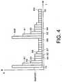
- the resulting series of measured capacitances (A) between the contacts 220 and 224forms a time-domain output signal, shown in figure 4 .
- the output signal necessary to detect the fluid boundariesis contained entirely within the time domain.
- the capacitance A1 of the completely water immersed sectionis lower by design (as described above).
- the capacitance A2 of the next sectionis slightly lower still because it is partially immersed in fuel, which has a lower dielectric constant than water.
- the capacitances A3, A4, A5 of the next three capacitorsare equal as they are all immersed in fuel.
- the capacitance A6 of the next sectionis slightly lower because it is only partially immersed in fuel, and the capacitance of the remaining sections A7 to AN is lower still because the dielectric constant of air is lower than that of fuel.
- the fuel and / or water levelcan be estimated by detecting a change in the capacitance at a specific time.
- TwThe time at which the capacitance changes from water to fuel (indicated by a drop in capacitance at A2) is denoted as Tw.
- TfThe time at which the capacitance changes from fuel to air (indicated by a drop in capacitance at A6) is denoted as Tf.
- a more accurate method of determining the height of water and / or fuelcan be used in which the capacitance of the transition probe (A2 or A6) is used.
- HwaccHp ⁇ Tw Tp + A 2 ⁇ A 3 N A 1 ⁇ A 3
- the level Hwhich is not as accurate as Hacc, can be used for alarms (e.g. if water exceeds a predetermined height).
- the level Hacccan be used for more accurate readings of fuel or water quantity within the tank.
- TDACtime domain analogue capacitance
- the probe 300comprises a first plurality of stacked flat conductive sections 302, from 1 to "N" sections. Typically, N+1 is a power of 2 (e.g. 8, 16, 32, 64 etc.). Adjacent to (but not in contact with) the stacked flat sections 302 is a second plurality of stacked flat conductive sections 304. Thus, pairs of flat conductive sections are formed. The sections are mounted on the outer surface of an electrically insulating fuel tank wall 306 containing a fluid 308.
- Each section 302, 304is identical, i.e. of equal height in the fuel fill direction, and equal width. Therefore each pair of sections can be assumed to have substantially the same capacitance properties when presented with the same dielectric substance as will be described below.
- a probe 400comprises a common flat conductive section 402 and a plurality of stacked flat conductive sections 404 proximate thereto.
- the sections 402, 404are mounted on the outer surface of an electrically insulating fuel tank wall 406 containing a fluid 408.
- FIG 6ca section through the plane C in figure 6b is shown.
- the electric field between the sections 402, 404passes through the fluid 408 and as such the dielectric constant of the fluid will affect the capacitance between the common section 402 and each of the individual sections 404.
- the platesdo not need to by cylindrical, and may be any shape as long as they define discrete capacitive regions.
- a multiplexerdoes not have to be used; a less preferable option is to continuously and simultaneously read the capacitance of each section.
- the probemay use a single, common outer plate and a plurality of inner plates. This may be advantageous if the capacitor is etched onto a carrier as it is easier to etch an outer surface of a carrier than an inner surface.
- sets of multiple opposed inner and outer platesmay be used.
- N+1is not a power of 2
- the counteris modified to count from 0 to N+1 and repeat.
- the number of counter bitsis then adjusted to the next highest power of 2.
Landscapes
- Physics & Mathematics (AREA)
- Engineering & Computer Science (AREA)
- Power Engineering (AREA)
- General Physics & Mathematics (AREA)
- Chemical & Material Sciences (AREA)
- Fluid Mechanics (AREA)
- Thermal Sciences (AREA)
- Electromagnetism (AREA)
- Health & Medical Sciences (AREA)
- Life Sciences & Earth Sciences (AREA)
- Analytical Chemistry (AREA)
- Biochemistry (AREA)
- General Health & Medical Sciences (AREA)
- Medicinal Chemistry (AREA)
- Immunology (AREA)
- Pathology (AREA)
- Food Science & Technology (AREA)
- Oil, Petroleum & Natural Gas (AREA)
- General Chemical & Material Sciences (AREA)
- Chemical Kinetics & Catalysis (AREA)
- Measurement Of Levels Of Liquids Or Fluent Solid Materials (AREA)
Description
- The present invention is concerned with an aircraft fuel tank fluid level measurement apparatus and method for measurement of fluid levels in aircraft fuel tanks. More specifically, the present invention is concerned with an aircraft wing fuel tank fuel, water and ice level measurement apparatus and method.
- Aircraft fuel tanks comprise vents in order to allow air in and out of the tank. This is because as the aircraft's altitude changes, the ambient pressure changes and therefore in order to avoid a significant pressure differential between the inside and outside of the fuel tank it is beneficial to allow ambient air to move in and out of the tank. This also allows air to replace the fuel used by the aircraft engines as the tank empties.
- A problem with venting aircraft fuel tanks is that moist air may be allowed into the tank. When the moist air is cooled by a reduction in ambient temperature, the water in the air condenses to a liquid.
- Fuel levels in modern aircraft are often monitored using a capacitive fuel probe. Such probes comprise a pair of offset plates (normally in the shape of a pair of concentric cylinders) between which fuel can enter. As the fuel level decreases, the annular area between the plates which contains fuel also decreases. Because the dielectric constant of the fuel is significantly higher than that of air, the capacitance of the probe changes with the fuel level, and can be measured in a low power circuit to determine the fuel level.
- A problem with some such capacitive probes is that they operate on the assumption that the dielectric constant of the fuel is known and is constant, and therefore the capacitance of the probe is proportional to the fuel level. This may not be the case, as the dielectric constant may change with the pressure and temperature of the fuel.
- One solution to this problem is that the dielectric constant of the fuel can be measured by using the fuel as the dielectric in a capacitor of known dimensions and properties. A problem with this approach is that the measurement equipment adds complexity and weight to the aircraft fuel system.
- A further problem with known capacitive probes is that when the water level rises in the tank (as previously described) a stratified fluid develops in which the probe is partially immersed in water at its base, a layer of fuel on top of the water and the remainder in air. The reading of the probe is thus distorted because the dielectric constant of water (about 80 times that of air) is significantly higher than that of fuel. Therefore the probe will indicate a higher capacitance than the equivalent level of fuel alone and report that the tank contains more fuel than it actually does.
- Capacitive probes have a large working range as they need to be able to report the fuel level from an empty to a full tank. A probe partially immersed in water will therefore not always provide a reading outside of its working range, rather it will report an erroneously high fuel level. Therefore the error is not always detectable by out-of-range readings. This is further complicated by the introduction of other substances such as ice.
- Erroneous fuel readings are clearly undesirable. What is required is a fuel tank measurement system that can determine the level of each individual substance of a stratified substance an aircraft fuel tank.
- It is an aim of the present invention to provide an improved fuel tank substance level detection apparatus and method.
- According to a first aspect of the invention there is provided a method of detecting boundaries within a stratified substance in an aircraft fuel tank according to claim 1. Further, optional, steps are recited in each of claims 2 and 3.
- According to a second aspect of the invention there is provided a fuel level measurement apparatus according to claim 4. Further, optional, features are recited in each of claims 5 to 9.
- By providing an output signal in the time domain, the invention minimises wiring to the central fuel processing computer. Less wiring is advantageous in aircraft applications in order to minimise weight and interference. Further, by using the subject method, existing aircraft architecture may be used and the present invention retrofitted thereto.
- All sections above the fuel level will have a first capacitance, and all below the fuel level will have a second, higher capacitance. Similarly, all sections below the water level (if present) will have a third capacitance higher than the second. In addition, if any ice has formed it will have a fourth capacitance higher than that of fuel, but lower than that of water. As such, by monitoring changes in the time domain signal as opposed to the absolute capacitance values, the dielectric constants of each constituent part of the stratified substance does not need to be known. This obviates the need for apparatus to measure or estimate the dielectric constants of the constituent substances.
- Preferably, the first reference capacitor is positioned at a first end of the plurality of discrete capacitive sections, and a second reference capacitor is provided at a second end of the plurality of discrete capacitive sections.
- An example fuel level measurement apparatus and method in accordance with the present invention will not be described with reference to the accompanying figures in which:
Figure 1 is a perspective view of a known capacitive probe,Figure 2 is a perspective view of a first capacitive probe in accordance with the present invention,Figure 3 is a circuit diagram of the capacitive probe offigure 2 ,Figure 4 is a graphic representation of the measured output of a probe according to the present invention,Figure 5 is a further example of an output of a probe in accordance with the present invention,Figure 6a is a perspective section view of a second capacitive probe in accordance with the present invention,Figure 6b is a perspective section view of a third capacitive probe in accordance with the present invention, and,Figure 6c is a section view of the capacitive probe offigure 6b .- Referring to
figure 1 , acapacitive probe 100 is installed within an aircraftwing fuel tank 102. Thefuel tank 102 containsfuel 104 to a level L. - The
capacitive probe 100 comprises an outercylindrical plate 106 and an innercylindrical plate 108 which are concentric. Thecylindrical plates annular capacitor 110. - The
probe 100 is not in contact with thetank 102 such that thefuel 104 can flow into, and out of, thecapacitor 110. A pair ofelectrical contacts 112 are connected to the outer andinner plates probe 100 in a known fashion. - As the
tank 102 fills and empties with thefuel 104, the capacitance of theprobe 100 changes because the dielectric constant of air (filling the tank space) is significantly lower than that of fuel. Therefore, the level L of thefuel 104 in the tank can be estimated providing the dielectric constant of thefuel 104 is known. - As mentioned, a problem with this type of
probe 100 is that the dielectric constant of fuel must be either estimated (introducing inaccuracies in the reading) or measured (which requires additional equipment). - Turning to
figure 2 , aprobe 200 in accordance with the present invention is shown. The probe comprises a plurality of stackedannular sections 202, from 1 to "N" sections. Typically, N+1 is a power of 2 (e.g. 8, 16, 32, 64 etc.). Eachsection 202 comprises anouter plate 204 and a commoninner plate 206 and eachsection 202 therefore acts independently as a capacitor. Theouter plates 204 are etched onto the inner surface of a carrier (not shown). Anaxial gap 205 at a single circumferential position is formed in theouter plates 204. Eachsection 202 comprises its own set ofcontacts 208 etched into the carrier and routed through thegap 205 for use in measurement of its capacitance as will be described below. Eachsection 202 is identical, i.e. of equal height in the fuel fill direction, and equal diameter. Therefore each section can be assumed to have substantially the same capacitance properties when presented with the same dielectric substance. - Each of the contacts is connected to a
multiplexing circuit 210 which will be described below. - As can be seen in
figure 2 , afuel tank 212 in which theprobe 200 is installed contains a layer ofwater 214 condensed from ingested atmospheric air (as described above). The tank also contains a layer offuel 216 and the remainder is filled withair 218. Thewater 214 sinks to the bottom of thetank 212 because it is denser than thefuel 216. - As can be seen, the lowest of the
annular sections 202 is completely immersed inwater 214, the next of theannular sections 202 is partly immersed inwater 214, and partly infuel 216, the next threeannular sections 202 are fully immersed infuel 216, the next section is partly immersed infuel 216 and partly immersed in theair 218, and the remainingsections 202 are exposed to theair 218 only. - This is typical of the situation in an aircraft wing fuel tank.
- Referring to
figure 3 , theprobe 200 is shown in circuit diagram form. Each of theN sections 202 is connected to onecommon contact 220, and the other to a 1:(N+1)analogue multiplexer 222 of themultiplexing circuit 210 via thecontacts 208. Themultiplexer 222 comprises anoutput 224 to a conventional capacitive probe measurement circuit (not shown) capable of measuring the capacitance between thecommon contact 220 and theoutput 224. An oscillator an m bit (where 2m = N+1)counter 226 is also provided to control themultiplexer 222. - A reference (sync)
capacitor 228 is provided which is not affected by the contents of thefuel tank 212. The reference (sync)capacitor 228 is also connected to thecommon contact 220, the 1:(N+1) analogue multiplexer 222 (thus providing N+1 inputs). The capacitance of thereference capacitor 228, Aref, is significantly higher than the capacitance of any of thesections 202 when immersed in water, and is typically 1000pF. - The
multiplexer 222 is configured to switch sequentially from the reference capacitor 228 (at time T0) to each of thesections 202 in turn, starting from the lowermost section (at time T1) to the uppermost section (at time TN) and then returns to the reference capacitor 228 (at time T0) and repeats the sequence. The resulting series of measured capacitances (A) between thecontacts figure 4 . Thus the output signal necessary to detect the fluid boundaries is contained entirely within the time domain. - Each capacitor returns a capacitance of An (n = 0(ref), 1, 2, 3 ... N) for a specific time interval "t" (a clocking period of the counter) determined by the oscillator and m bit counter 226. As can be see in
figure 4 , the reference capacitance Aref = A0 (at T0) is the highest. The capacitance A1 of the completely water immersed section is lower by design (as described above). The capacitance A2 of the next section is slightly lower still because it is partially immersed in fuel, which has a lower dielectric constant than water. The capacitances A3, A4, A5 of the next three capacitors are equal as they are all immersed in fuel. The capacitance A6 of the next section is slightly lower because it is only partially immersed in fuel, and the capacitance of the remaining sections A7 to AN is lower still because the dielectric constant of air is lower than that of fuel. - As can be seen, the cycle repeats starting with the reference capacitance Aref=A0 at T0.
- The height of the
probe 200 is known = Hp. The fuel and / or water level can be estimated by detecting a change in the capacitance at a specific time. - The complete cycle takes time Tp = (N+1)*t.
- The time at which the capacitance changes from water to fuel (indicated by a drop in capacitance at A2) is denoted as Tw.
- Therefore the water height can be calculated as Hw = Hp * (Tw/Tp).
- The time at which the capacitance changes from fuel to air (indicated by a drop in capacitance at A6) is denoted as Tf.
- Therefore the fuel height can be calculated as Hf = Hp∗ (Tf/Tp).
- A more accurate method of determining the height of water and / or fuel can be used in which the capacitance of the transition probe (A2 or A6) is used.
- Therefore a more accurate water height can be determined by:

- A more accurate fuel height can be determined by:

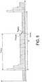
- Obviously, these methods are applicable generically, and following any change in capacitance, the height at which the dielectric constant changes (and hence fluid type changes) is calculated by:


- Ttrans = the time at which the transition section provides the first change in capacitance,
- Atrans = the capacitance of the transition section,
- Abelow = the capacitance of the section following the transition section, and
- Aabove = the capacitance of the section preceding the transition section, as shown in
figure 5 . - The level H, which is not as accurate as Hacc, can be used for alarms (e.g. if water exceeds a predetermined height). The level Hacc can be used for more accurate readings of fuel or water quantity within the tank.
- Many such readings are taken over a significant time interval (where Tp = 1 second and 10 readings are taken over 10 seconds), which results are filtered to eliminate erroneous results from e.g. sloshing in the tank.
- Because a time domain analogue capacitance (TDAC) probe as described above recognises changes in capacitance of the sections, the dielectric constants of the various fluids in the tank are not required. Therefore the invention offers significant advantages over known systems.
- In the above embodiment, each
section 202 where N+1= 32, diameter ofouter plate 204 = 20mm,inner plate 206 = 16mm, the capacitance:in air =7.8pF, in fuel =16.5pF (Jet-A) in ice =32.5pF in water =625pF. - Referring to
figure 6a , an alternative aprobe 300 in accordance with the present invention is shown. Theprobe 300 comprises a first plurality of stacked flatconductive sections 302, from 1 to "N" sections. Typically, N+1 is a power of 2 (e.g. 8, 16, 32, 64 etc.). Adjacent to (but not in contact with) the stackedflat sections 302 is a second plurality of stacked flatconductive sections 304. Thus, pairs of flat conductive sections are formed. The sections are mounted on the outer surface of an electrically insulatingfuel tank wall 306 containing a fluid 308. - Each
section - Referring to
figure 6b , a similar arrangement to that offigure 6a , but aprobe 400 comprises a common flatconductive section 402 and a plurality of stacked flatconductive sections 404 proximate thereto. Thesections fuel tank wall 406 containing a fluid 408. - Referring to
figure 6c , a section through the plane C infigure 6b is shown. As can be seen, the electric field between thesections common section 402 and each of theindividual sections 404. - Variations of the above apparatus and method fall within the scope of the present invention.
- The plates do not need to by cylindrical, and may be any shape as long as they define discrete capacitive regions.
- A multiplexer does not have to be used; a less preferable option is to continuously and simultaneously read the capacitance of each section.
- Instead of using multiple sets of outer plates, the probe may use a single, common outer plate and a plurality of inner plates. This may be advantageous if the capacitor is etched onto a carrier as it is easier to etch an outer surface of a carrier than an inner surface. Alternatively, sets of multiple opposed inner and outer plates may be used.
- If N+1 is not a power of 2, the counter is modified to count from 0 to N+1 and repeat. The number of counter bits is then adjusted to the next highest power of 2.


Claims (9)
- A method of detecting boundaries within a stratified substance in an aircraft fuel tank (212) comprising the steps of:providing a capacitive fuel probe (200) comprising a plurality of discrete capacitive sections (202),immersing the capacitive fuel probe in a stratified substance (214, 216, 218) in an aircraft fuel tank (212),sequentially measuring the capacitance of each of the plurality of discrete capacitive sections (202) at predetermined time intervals (t) to create a time-domain output signal,detecting a change in the time-domain output signal,calculating the location of a boundary along the fuel probe (200) within the stratified substance based on the time of the change (Tw) in the time-domain output signal, and,characterised by:providing a first reference capacitor (228) at a known position on the capacitive fuel probe (200), the reference capacitor having a capacitance outside of the expected capacitive range of each element of the stratified substance, and,detecting the first reference capacitor (228) by detecting the capacitance outside of the expected capacitive range of the stratified substance,in which the location of the boundary (Tw) is calculated by determining the time between the detection of the reference capacitor (228) and the detection of the change in capacitance in the time-domain output signal.
- A method of detecting boundaries according to claim 1 in which:
the fuel probe (200) comprises a multiplexer (222) arranged to sequentially measure the capacitance of each of the discrete capacitive sections at a predetermined time interval to create the time domain output signal. - A method of detecting boundaries according to claim 1 or claim 2 comprising the step of:
calculating a precise location of the boundary within a discrete capacitive section by:determining a transition section having a transition capacitance,calculating the location of the boundary within the transition section by interpolating the transition capacitance with respect to the capacitance of the preceding discrete capacitive section and following discrete capacitive section in the time domain output signal. - A fuel level measurement apparatus comprising;
a capacitive fuel probe (200) defining a fuel fill direction, the capacitive fuel probe having a plurality of discrete capacitive sections (202) in the fuel fill direction,
a circuit (210) arranged to provide a time domain output signal representative of the capacitance of each of the plurality of discrete capacitive sections in turn,
a processor configured to calculate the location of a boundary within a stratified substance in which the fuel probe (200) is immersed from the time of a change in the time-domain output signal,
characterised by:a first reference capacitor (228) at a first position on the capacitive fuel probe, the reference capacitor (228) having a capacitance (Aref) outside of the expected capacitive range of each element of the stratified substance, and,in which the processor is configured to calculate the location of the boundary by determining the time between the detection of the reference capacitor and the detection of the change in the time-domain output signal. - A fuel level measurement apparatus according to claim 4 comprising a multiplexer (222) arranged to sequentially measure the capacitance of each of the discrete capacitive sections at a predetermined time interval to create the time domain output signal.
- A fuel level measurement apparatus according to claim 5 in which the multiplexer is integral with the fuel probe.
- A fuel level measurement apparatus according to any of claims 4 to 6 in which the processor is configured to:
calculate a precise location of the boundary within a discrete capacitive section by:determining a transition section having a transition capacitance,calculating the location of the boundary within the transition section by interpolating the transition capacitance with respect to the capacitance of the preceding discrete capacitive section and following discrete capacitive section in the time domain output signal. - A fuel level measurement apparatus according to any of claims 4 to 7 in which each of the plurality of discrete capacitive sections (202) is of equal length in the fuel fill direction.
- A fuel level measurement apparatus according to any of claims 4 to 8 in which each of the plurality of discrete capacitive sections (202) comprises a pair of diametrically opposed axial slits such that each discrete capacitive section comprises a first discrete sub-region and a second discrete sub-region.
Applications Claiming Priority (2)
| Application Number | Priority Date | Filing Date | Title |
|---|---|---|---|
| GBGB0909510.0AGB0909510D0 (en) | 2009-06-03 | 2009-06-03 | Fuel level measurement apparatus and method |
| PCT/GB2010/050845WO2010139974A1 (en) | 2009-06-03 | 2010-05-24 | Aircraft fuel level measurement apparatus and method |
Publications (2)
| Publication Number | Publication Date |
|---|---|
| EP2438405A1 EP2438405A1 (en) | 2012-04-11 |
| EP2438405B1true EP2438405B1 (en) | 2019-09-18 |
Family
ID=40902499
Family Applications (1)
| Application Number | Title | Priority Date | Filing Date |
|---|---|---|---|
| EP10722397.6AActiveEP2438405B1 (en) | 2009-06-03 | 2010-05-24 | Aircraft fuel level measurement apparatus and method |
Country Status (4)
| Country | Link |
|---|---|
| US (1) | US9354099B2 (en) |
| EP (1) | EP2438405B1 (en) |
| GB (1) | GB0909510D0 (en) |
| WO (1) | WO2010139974A1 (en) |
Families Citing this family (22)
| Publication number | Priority date | Publication date | Assignee | Title |
|---|---|---|---|---|
| US8281655B2 (en) | 2009-04-03 | 2012-10-09 | Eaton Corporation | Fuel gauging system utilizing a digital fuel gauging probe |
| GB201102401D0 (en) | 2011-02-10 | 2011-03-30 | Oxford Rf Sensors Ltd | Fluid sensor |
| US9035800B2 (en)* | 2012-10-12 | 2015-05-19 | The Boeing Company | Fuel tank monitoring system |
| US9293033B2 (en) | 2013-07-16 | 2016-03-22 | The Boeing Company | Wireless fuel sensor system |
| GB2519783A (en)* | 2013-10-30 | 2015-05-06 | Airbus Operations Ltd | Capacitive liquid level sensor |
| WO2015181770A2 (en) | 2014-05-30 | 2015-12-03 | Eltek S.P.A. | A sensor for detecting the level of a medium |
| WO2016042456A2 (en) | 2014-09-15 | 2016-03-24 | Eltek S.P.A. | Sensor for detecting the level of a medium |
| BR112017005012B1 (en)* | 2014-09-15 | 2021-03-30 | Eltek S.P.A. | SENSOR TO DETECT THE LEVEL OF A MEDIA CONTAINED IN A CONTAINER, METHOD TO CONTROL A SENSOR TO DETECT THE LEVEL OF A MEDIA CONTAINED IN A CONTAINER, CONTAINER, AND METHOD CHARACTERIZED BY THE FACT THAT IS TO CONTROL A SENSOR TO DETECT THE LEVEL OF A CONTAINER QUITE |
| EP3280983A4 (en)* | 2015-04-10 | 2019-01-02 | CoVar Applied Technologies, Inc. | Discrete capacitive flow stream height measurement for partially filled pipes |
| US9153119B2 (en)* | 2015-04-23 | 2015-10-06 | Scott Stapleford | Scenting nebulizer with remote management and capacitive liquid level sensing |
| DE102015223868B4 (en)* | 2015-12-01 | 2024-02-22 | Ifm Electronic Gmbh | Arrangement and method for capacitive level determination |
| DE102015016775A1 (en)* | 2015-12-23 | 2017-06-29 | Audi Ag | Method for operating a sensor arrangement for a fluid tank of a motor vehicle and corresponding sensor arrangement |
| ITUA20164407A1 (en)* | 2016-06-15 | 2017-12-15 | Eltek Spa | SENSOR FOR DETECTION OF THE LEVEL OF A MEDIA |
| ITUA20164400A1 (en)* | 2016-06-15 | 2017-12-15 | Eltek Spa | SENSOR FOR DETECTION OF THE LEVEL OF A MEDIA |
| ITUA20164395A1 (en)* | 2016-06-15 | 2017-12-15 | Eltek Spa | SENSOR FOR DETECTION OF THE LEVEL OF A MEDIA |
| ES2773181T3 (en)* | 2017-02-22 | 2020-07-09 | Zodiac Aerotechnics | Condenser fuel probe |
| US10830469B2 (en)* | 2017-08-01 | 2020-11-10 | D-M-S Holdings, Inc. | Humidifier measurement and control |
| US20190041086A1 (en)* | 2017-08-01 | 2019-02-07 | D-M-S Holdings, Inc. | Humidifier liquid tank |
| US10760937B2 (en)* | 2017-09-08 | 2020-09-01 | RV Whisper LLC | System and method for measuring the level of fluid in a container |
| EP3457096B1 (en)* | 2017-09-13 | 2021-07-07 | Intersens | Improved probe for fill limiting device for petroleum fuel transport tank and corresponding fill limiting device |
| FR3071054B1 (en)* | 2017-09-13 | 2021-01-29 | Intersens | PROBE FOR FILLING LIMITER DEVICE FOR LIQUID OIL FUEL TRANSPORT TANK AND CORRESPONDING FILLING LIMITER DEVICE |
| CN113144339B (en)* | 2021-04-13 | 2023-08-01 | 山东亚华电子股份有限公司 | Infusion monitoring device |
Family Cites Families (17)
| Publication number | Priority date | Publication date | Assignee | Title |
|---|---|---|---|---|
| NO742093L (en)* | 1974-06-10 | 1975-12-11 | Navaltronic As | |
| US4099167A (en) | 1977-02-10 | 1978-07-04 | P.R. Mallory & Co. Inc. | Capacitive means for measuring the level of a liquid |
| US4601201A (en) | 1984-03-14 | 1986-07-22 | Tokyo Tatsuno Co., Ltd. | Liquid level and quantity measuring apparatus |
| JPS60192227A (en) | 1984-03-14 | 1985-09-30 | Tokyo Tatsuno Co Ltd | Electrode for electrostatic capacity type level gauge |
| US5103368A (en)* | 1990-05-07 | 1992-04-07 | Therm-O-Disc, Incorporated | Capacitive fluid level sensor |
| US5613399A (en) | 1993-10-27 | 1997-03-25 | Kdi Precision Products, Inc. | Method for liquid level detection |
| US5406843A (en) | 1993-10-27 | 1995-04-18 | Kdi Corporation, Inc. | Digital liquid level sensing apparatus |
| US6101873A (en)* | 1996-05-17 | 2000-08-15 | Nohken Inc. | Level sensor |
| DE19630075A1 (en) | 1996-07-26 | 1998-05-28 | Gerhard Dipl Ing Wergen | Multi-dimensional handle |
| WO1998033044A1 (en) | 1997-01-28 | 1998-07-30 | Abb Research Ltd. | Capacitative level detector with optimized electrode geometry |
| DE19713267A1 (en) | 1997-01-28 | 1998-07-30 | Abb Research Ltd | Method for determining the dielectric constant and / or the conductivity of at least one medium and device for carrying out the method |
| JPH11311562A (en) | 1998-04-27 | 1999-11-09 | Wako:Kk | Water level sensor |
| DE10008093B4 (en)* | 2000-02-22 | 2007-07-05 | Ifm Electronic Gmbh | Capacitive level gauge |
| US6568264B2 (en)* | 2001-02-23 | 2003-05-27 | Charles E. Heger | Wireless swimming pool water level system |
| DE10345707A1 (en) | 2003-10-01 | 2005-04-21 | Volkswagen Ag | Method for level detection in a container and corresponding level measurement system |
| WO2008049913A1 (en)* | 2006-10-26 | 2008-05-02 | Inergy Automotive Systems Research (Société Anonyme) | Process for measuring a liquid level in a tank and associated system |
| EP2034282A1 (en) | 2007-07-19 | 2009-03-11 | Siemens Milltronics Process Instruments Inc. | Method and apparatus for measuring medium layers and interfaces between them using a multi-sensor probe |
- 2009
- 2009-06-03GBGBGB0909510.0Apatent/GB0909510D0/ennot_activeCeased
- 2010
- 2010-05-24WOPCT/GB2010/050845patent/WO2010139974A1/enactiveApplication Filing
- 2010-05-24USUS13/319,166patent/US9354099B2/enactiveActive
- 2010-05-24EPEP10722397.6Apatent/EP2438405B1/enactiveActive
Non-Patent Citations (1)
| Title |
|---|
| None* |
Also Published As
| Publication number | Publication date |
|---|---|
| WO2010139974A1 (en) | 2010-12-09 |
| US9354099B2 (en) | 2016-05-31 |
| EP2438405A1 (en) | 2012-04-11 |
| GB0909510D0 (en) | 2009-07-15 |
| US20120065904A1 (en) | 2012-03-15 |
Similar Documents
| Publication | Publication Date | Title |
|---|---|---|
| EP2438405B1 (en) | Aircraft fuel level measurement apparatus and method | |
| US20130276533A1 (en) | Device for measuring fluid level in a container | |
| US20150033830A1 (en) | Automated phase separation and fuel quality sensor | |
| CN101981415B (en) | Method for measuring the volume flow of electrically conductive liquids through a vessel | |
| US20130298667A1 (en) | Apparatus and Method for Capacitive Fill Level Measurement | |
| US10371555B2 (en) | Capacitive continuous fluid level sensor | |
| US20070252715A1 (en) | Liquid quality and level sensor | |
| CN103376144A (en) | Liquid level detecting device | |
| US12326354B2 (en) | Capacitive filling level probe without dead zone | |
| US20120291541A1 (en) | Digital field-induction water-level intelligent sensing system and its implementation method | |
| KR20210154139A (en) | Dual Polarity Mutual Capacitive Liquid Detection | |
| EP1212607B1 (en) | Method of measuring water content | |
| US10114139B1 (en) | Multi-capacitor liquid detection device and method(s) of use | |
| CN117607190A (en) | Liquid heating container and liquid heating state monitoring device based on fluctuation discrimination | |
| CN116642556A (en) | Non-contact measuring sensor for liquid volume of container based on twice measuring method | |
| JP6132482B2 (en) | Liquid level detector | |
| KR20170104748A (en) | An apparatus for detecting level of the fluid in the tank using a plurality of pcb pad | |
| EP3130896B1 (en) | Liquid level sensor with insulating region over the probe foot | |
| US12442676B2 (en) | Differentiating between fuel and water using capacitive measurement thereof | |
| CN111206376A (en) | Liquid level detection device and method and washing machine | |
| US20220316935A1 (en) | Differentiating between fuel and water using capacitive measurement thereof | |
| CN220794357U (en) | Liquid storage container and liquid level measuring sensor thereof | |
| CN111206393A (en) | Liquid level detection device and method and washing machine | |
| JP5692020B2 (en) | Liquid level detector | |
| CN117630088A (en) | Liquid heating container and liquid heating state monitoring device based on difference discrimination |
Legal Events
| Date | Code | Title | Description |
|---|---|---|---|
| PUAI | Public reference made under article 153(3) epc to a published international application that has entered the european phase | Free format text:ORIGINAL CODE: 0009012 | |
| 17P | Request for examination filed | Effective date:20111201 | |
| AK | Designated contracting states | Kind code of ref document:A1 Designated state(s):AL AT BE BG CH CY CZ DE DK EE ES FI FR GB GR HR HU IE IS IT LI LT LU LV MC MK MT NL NO PL PT RO SE SI SK SM TR | |
| DAX | Request for extension of the european patent (deleted) | ||
| 17Q | First examination report despatched | Effective date:20161006 | |
| STAA | Information on the status of an ep patent application or granted ep patent | Free format text:STATUS: EXAMINATION IS IN PROGRESS | |
| RIC1 | Information provided on ipc code assigned before grant | Ipc:G01F 23/26 20060101AFI20190130BHEP Ipc:G01N 33/28 20060101ALI20190130BHEP | |
| GRAP | Despatch of communication of intention to grant a patent | Free format text:ORIGINAL CODE: EPIDOSNIGR1 | |
| STAA | Information on the status of an ep patent application or granted ep patent | Free format text:STATUS: GRANT OF PATENT IS INTENDED | |
| INTG | Intention to grant announced | Effective date:20190409 | |
| GRAS | Grant fee paid | Free format text:ORIGINAL CODE: EPIDOSNIGR3 | |
| GRAA | (expected) grant | Free format text:ORIGINAL CODE: 0009210 | |
| STAA | Information on the status of an ep patent application or granted ep patent | Free format text:STATUS: THE PATENT HAS BEEN GRANTED | |
| AK | Designated contracting states | Kind code of ref document:B1 Designated state(s):AL AT BE BG CH CY CZ DE DK EE ES FI FR GB GR HR HU IE IS IT LI LT LU LV MC MK MT NL NO PL PT RO SE SI SK SM TR | |
| REG | Reference to a national code | Ref country code:GB Ref legal event code:FG4D | |
| REG | Reference to a national code | Ref country code:CH Ref legal event code:EP | |
| REG | Reference to a national code | Ref country code:DE Ref legal event code:R096 Ref document number:602010061097 Country of ref document:DE | |
| REG | Reference to a national code | Ref country code:AT Ref legal event code:REF Ref document number:1181884 Country of ref document:AT Kind code of ref document:T Effective date:20191015 | |
| REG | Reference to a national code | Ref country code:IE Ref legal event code:FG4D | |
| REG | Reference to a national code | Ref country code:NL Ref legal event code:MP Effective date:20190918 | |
| PG25 | Lapsed in a contracting state [announced via postgrant information from national office to epo] | Ref country code:HR Free format text:LAPSE BECAUSE OF FAILURE TO SUBMIT A TRANSLATION OF THE DESCRIPTION OR TO PAY THE FEE WITHIN THE PRESCRIBED TIME-LIMIT Effective date:20190918 Ref country code:BG Free format text:LAPSE BECAUSE OF FAILURE TO SUBMIT A TRANSLATION OF THE DESCRIPTION OR TO PAY THE FEE WITHIN THE PRESCRIBED TIME-LIMIT Effective date:20191218 Ref country code:SE Free format text:LAPSE BECAUSE OF FAILURE TO SUBMIT A TRANSLATION OF THE DESCRIPTION OR TO PAY THE FEE WITHIN THE PRESCRIBED TIME-LIMIT Effective date:20190918 Ref country code:LT Free format text:LAPSE BECAUSE OF FAILURE TO SUBMIT A TRANSLATION OF THE DESCRIPTION OR TO PAY THE FEE WITHIN THE PRESCRIBED TIME-LIMIT Effective date:20190918 Ref country code:FI Free format text:LAPSE BECAUSE OF FAILURE TO SUBMIT A TRANSLATION OF THE DESCRIPTION OR TO PAY THE FEE WITHIN THE PRESCRIBED TIME-LIMIT Effective date:20190918 Ref country code:NO Free format text:LAPSE BECAUSE OF FAILURE TO SUBMIT A TRANSLATION OF THE DESCRIPTION OR TO PAY THE FEE WITHIN THE PRESCRIBED TIME-LIMIT Effective date:20191218 | |
| REG | Reference to a national code | Ref country code:LT Ref legal event code:MG4D | |
| PG25 | Lapsed in a contracting state [announced via postgrant information from national office to epo] | Ref country code:GR Free format text:LAPSE BECAUSE OF FAILURE TO SUBMIT A TRANSLATION OF THE DESCRIPTION OR TO PAY THE FEE WITHIN THE PRESCRIBED TIME-LIMIT Effective date:20191219 Ref country code:LV Free format text:LAPSE BECAUSE OF FAILURE TO SUBMIT A TRANSLATION OF THE DESCRIPTION OR TO PAY THE FEE WITHIN THE PRESCRIBED TIME-LIMIT Effective date:20190918 Ref country code:AL Free format text:LAPSE BECAUSE OF FAILURE TO SUBMIT A TRANSLATION OF THE DESCRIPTION OR TO PAY THE FEE WITHIN THE PRESCRIBED TIME-LIMIT Effective date:20190918 | |
| REG | Reference to a national code | Ref country code:AT Ref legal event code:MK05 Ref document number:1181884 Country of ref document:AT Kind code of ref document:T Effective date:20190918 | |
| PG25 | Lapsed in a contracting state [announced via postgrant information from national office to epo] | Ref country code:NL Free format text:LAPSE BECAUSE OF FAILURE TO SUBMIT A TRANSLATION OF THE DESCRIPTION OR TO PAY THE FEE WITHIN THE PRESCRIBED TIME-LIMIT Effective date:20190918 Ref country code:PT Free format text:LAPSE BECAUSE OF FAILURE TO SUBMIT A TRANSLATION OF THE DESCRIPTION OR TO PAY THE FEE WITHIN THE PRESCRIBED TIME-LIMIT Effective date:20200120 Ref country code:ES Free format text:LAPSE BECAUSE OF FAILURE TO SUBMIT A TRANSLATION OF THE DESCRIPTION OR TO PAY THE FEE WITHIN THE PRESCRIBED TIME-LIMIT Effective date:20190918 Ref country code:EE Free format text:LAPSE BECAUSE OF FAILURE TO SUBMIT A TRANSLATION OF THE DESCRIPTION OR TO PAY THE FEE WITHIN THE PRESCRIBED TIME-LIMIT Effective date:20190918 Ref country code:AT Free format text:LAPSE BECAUSE OF FAILURE TO SUBMIT A TRANSLATION OF THE DESCRIPTION OR TO PAY THE FEE WITHIN THE PRESCRIBED TIME-LIMIT Effective date:20190918 Ref country code:RO Free format text:LAPSE BECAUSE OF FAILURE TO SUBMIT A TRANSLATION OF THE DESCRIPTION OR TO PAY THE FEE WITHIN THE PRESCRIBED TIME-LIMIT Effective date:20190918 Ref country code:IT Free format text:LAPSE BECAUSE OF FAILURE TO SUBMIT A TRANSLATION OF THE DESCRIPTION OR TO PAY THE FEE WITHIN THE PRESCRIBED TIME-LIMIT Effective date:20190918 Ref country code:PL Free format text:LAPSE BECAUSE OF FAILURE TO SUBMIT A TRANSLATION OF THE DESCRIPTION OR TO PAY THE FEE WITHIN THE PRESCRIBED TIME-LIMIT Effective date:20190918 | |
| PG25 | Lapsed in a contracting state [announced via postgrant information from national office to epo] | Ref country code:SM Free format text:LAPSE BECAUSE OF FAILURE TO SUBMIT A TRANSLATION OF THE DESCRIPTION OR TO PAY THE FEE WITHIN THE PRESCRIBED TIME-LIMIT Effective date:20190918 Ref country code:IS Free format text:LAPSE BECAUSE OF FAILURE TO SUBMIT A TRANSLATION OF THE DESCRIPTION OR TO PAY THE FEE WITHIN THE PRESCRIBED TIME-LIMIT Effective date:20200224 Ref country code:SK Free format text:LAPSE BECAUSE OF FAILURE TO SUBMIT A TRANSLATION OF THE DESCRIPTION OR TO PAY THE FEE WITHIN THE PRESCRIBED TIME-LIMIT Effective date:20190918 Ref country code:CZ Free format text:LAPSE BECAUSE OF FAILURE TO SUBMIT A TRANSLATION OF THE DESCRIPTION OR TO PAY THE FEE WITHIN THE PRESCRIBED TIME-LIMIT Effective date:20190918 | |
| REG | Reference to a national code | Ref country code:DE Ref legal event code:R097 Ref document number:602010061097 Country of ref document:DE | |
| PLBE | No opposition filed within time limit | Free format text:ORIGINAL CODE: 0009261 | |
| STAA | Information on the status of an ep patent application or granted ep patent | Free format text:STATUS: NO OPPOSITION FILED WITHIN TIME LIMIT | |
| PG2D | Information on lapse in contracting state deleted | Ref country code:IS | |
| PG25 | Lapsed in a contracting state [announced via postgrant information from national office to epo] | Ref country code:DK Free format text:LAPSE BECAUSE OF FAILURE TO SUBMIT A TRANSLATION OF THE DESCRIPTION OR TO PAY THE FEE WITHIN THE PRESCRIBED TIME-LIMIT Effective date:20190918 Ref country code:IS Free format text:LAPSE BECAUSE OF FAILURE TO SUBMIT A TRANSLATION OF THE DESCRIPTION OR TO PAY THE FEE WITHIN THE PRESCRIBED TIME-LIMIT Effective date:20200119 | |
| 26N | No opposition filed | Effective date:20200619 | |
| PG25 | Lapsed in a contracting state [announced via postgrant information from national office to epo] | Ref country code:SI Free format text:LAPSE BECAUSE OF FAILURE TO SUBMIT A TRANSLATION OF THE DESCRIPTION OR TO PAY THE FEE WITHIN THE PRESCRIBED TIME-LIMIT Effective date:20190918 | |
| PG25 | Lapsed in a contracting state [announced via postgrant information from national office to epo] | Ref country code:MC Free format text:LAPSE BECAUSE OF FAILURE TO SUBMIT A TRANSLATION OF THE DESCRIPTION OR TO PAY THE FEE WITHIN THE PRESCRIBED TIME-LIMIT Effective date:20190918 Ref country code:LI Free format text:LAPSE BECAUSE OF NON-PAYMENT OF DUE FEES Effective date:20200531 Ref country code:CH Free format text:LAPSE BECAUSE OF NON-PAYMENT OF DUE FEES Effective date:20200531 | |
| REG | Reference to a national code | Ref country code:BE Ref legal event code:MM Effective date:20200531 | |
| PG25 | Lapsed in a contracting state [announced via postgrant information from national office to epo] | Ref country code:LU Free format text:LAPSE BECAUSE OF NON-PAYMENT OF DUE FEES Effective date:20200524 | |
| PG25 | Lapsed in a contracting state [announced via postgrant information from national office to epo] | Ref country code:IE Free format text:LAPSE BECAUSE OF NON-PAYMENT OF DUE FEES Effective date:20200524 | |
| PG25 | Lapsed in a contracting state [announced via postgrant information from national office to epo] | Ref country code:BE Free format text:LAPSE BECAUSE OF NON-PAYMENT OF DUE FEES Effective date:20200531 | |
| PG25 | Lapsed in a contracting state [announced via postgrant information from national office to epo] | Ref country code:TR Free format text:LAPSE BECAUSE OF FAILURE TO SUBMIT A TRANSLATION OF THE DESCRIPTION OR TO PAY THE FEE WITHIN THE PRESCRIBED TIME-LIMIT Effective date:20190918 Ref country code:MT Free format text:LAPSE BECAUSE OF FAILURE TO SUBMIT A TRANSLATION OF THE DESCRIPTION OR TO PAY THE FEE WITHIN THE PRESCRIBED TIME-LIMIT Effective date:20190918 Ref country code:CY Free format text:LAPSE BECAUSE OF FAILURE TO SUBMIT A TRANSLATION OF THE DESCRIPTION OR TO PAY THE FEE WITHIN THE PRESCRIBED TIME-LIMIT Effective date:20190918 | |
| PG25 | Lapsed in a contracting state [announced via postgrant information from national office to epo] | Ref country code:MK Free format text:LAPSE BECAUSE OF FAILURE TO SUBMIT A TRANSLATION OF THE DESCRIPTION OR TO PAY THE FEE WITHIN THE PRESCRIBED TIME-LIMIT Effective date:20190918 | |
| PGFP | Annual fee paid to national office [announced via postgrant information from national office to epo] | Ref country code:DE Payment date:20250521 Year of fee payment:16 | |
| PGFP | Annual fee paid to national office [announced via postgrant information from national office to epo] | Ref country code:GB Payment date:20250526 Year of fee payment:16 | |
| PGFP | Annual fee paid to national office [announced via postgrant information from national office to epo] | Ref country code:FR Payment date:20250528 Year of fee payment:16 |