EP2433868B1 - Improved de-icing system for a fixed or rotary wing of an aircraft - Google Patents
Improved de-icing system for a fixed or rotary wing of an aircraftDownload PDFInfo
- Publication number
- EP2433868B1 EP2433868B1EP11007542.1AEP11007542AEP2433868B1EP 2433868 B1EP2433868 B1EP 2433868B1EP 11007542 AEP11007542 AEP 11007542AEP 2433868 B1EP2433868 B1EP 2433868B1
- Authority
- EP
- European Patent Office
- Prior art keywords
- leading edge
- wing element
- element according
- aircraft wing
- piezoelectric actuators
- Prior art date
- Legal status (The legal status is an assumption and is not a legal conclusion. Google has not performed a legal analysis and makes no representation as to the accuracy of the status listed.)
- Active
Links
- 239000011347resinSubstances0.000claimsdescription26
- 229920005989resinPolymers0.000claimsdescription26
- 229920001971elastomerPolymers0.000claimsdescription21
- 239000000806elastomerSubstances0.000claimsdescription21
- 239000000919ceramicSubstances0.000claimsdescription12
- 238000002604ultrasonographyMethods0.000claimsdescription12
- 239000000463materialSubstances0.000claimsdescription9
- 238000004026adhesive bondingMethods0.000claimsdescription6
- 239000000853adhesiveSubstances0.000claimsdescription4
- 230000001070adhesive effectEffects0.000claimsdescription4
- 239000002313adhesive filmSubstances0.000claimsdescription3
- 229920001084poly(chloroprene)Polymers0.000claimsdescription3
- 229920001296polysiloxanePolymers0.000claimsdescription3
- 230000000295complement effectEffects0.000description5
- 238000010257thawingMethods0.000description5
- 239000003292glueSubstances0.000description3
- 238000012423maintenanceMethods0.000description3
- 230000005540biological transmissionEffects0.000description2
- 230000015572biosynthetic processEffects0.000description2
- 239000011248coating agentSubstances0.000description2
- 238000000576coating methodMethods0.000description2
- 230000032798delaminationEffects0.000description2
- 230000001627detrimental effectEffects0.000description2
- 239000000428dustSubstances0.000description2
- 238000009434installationMethods0.000description2
- 230000010354integrationEffects0.000description2
- 238000010008shearingMethods0.000description2
- 239000004593EpoxySubstances0.000description1
- 229910000831SteelInorganic materials0.000description1
- RTAQQCXQSZGOHL-UHFFFAOYSA-NTitaniumChemical compound[Ti]RTAQQCXQSZGOHL-UHFFFAOYSA-N0.000description1
- 238000005299abrasionMethods0.000description1
- 229910052782aluminiumInorganic materials0.000description1
- XAGFODPZIPBFFR-UHFFFAOYSA-NaluminiumChemical compound[Al]XAGFODPZIPBFFR-UHFFFAOYSA-N0.000description1
- 239000002131composite materialSubstances0.000description1
- 238000013016dampingMethods0.000description1
- 230000000694effectsEffects0.000description1
- 238000005516engineering processMethods0.000description1
- 230000005284excitationEffects0.000description1
- 230000002349favourable effectEffects0.000description1
- 239000000835fiberSubstances0.000description1
- 238000007667floatingMethods0.000description1
- 238000010438heat treatmentMethods0.000description1
- 238000002513implantationMethods0.000description1
- 238000005304joiningMethods0.000description1
- 238000004519manufacturing processMethods0.000description1
- 239000011159matrix materialSubstances0.000description1
- 229910052751metalInorganic materials0.000description1
- 239000002184metalSubstances0.000description1
- 238000000034methodMethods0.000description1
- 230000008520organizationEffects0.000description1
- 230000036316preloadEffects0.000description1
- 230000001681protective effectEffects0.000description1
- 239000010959steelSubstances0.000description1
- 239000010936titaniumSubstances0.000description1
- 229910052719titaniumInorganic materials0.000description1
- 230000003313weakening effectEffects0.000description1
Images


Classifications
- B—PERFORMING OPERATIONS; TRANSPORTING
- B64—AIRCRAFT; AVIATION; COSMONAUTICS
- B64D—EQUIPMENT FOR FITTING IN OR TO AIRCRAFT; FLIGHT SUITS; PARACHUTES; ARRANGEMENT OR MOUNTING OF POWER PLANTS OR PROPULSION TRANSMISSIONS IN AIRCRAFT
- B64D15/00—De-icing or preventing icing on exterior surfaces of aircraft
- B64D15/16—De-icing or preventing icing on exterior surfaces of aircraft by mechanical means, e.g. pulsating mats or shoes attached to, or built into, surface
- B64D15/163—De-icing or preventing icing on exterior surfaces of aircraft by mechanical means, e.g. pulsating mats or shoes attached to, or built into, surface using electro-impulsive devices
- B—PERFORMING OPERATIONS; TRANSPORTING
- B06—GENERATING OR TRANSMITTING MECHANICAL VIBRATIONS IN GENERAL
- B06B—METHODS OR APPARATUS FOR GENERATING OR TRANSMITTING MECHANICAL VIBRATIONS OF INFRASONIC, SONIC, OR ULTRASONIC FREQUENCY, e.g. FOR PERFORMING MECHANICAL WORK IN GENERAL
- B06B1/00—Methods or apparatus for generating mechanical vibrations of infrasonic, sonic, or ultrasonic frequency
- B06B1/02—Methods or apparatus for generating mechanical vibrations of infrasonic, sonic, or ultrasonic frequency making use of electrical energy
- B06B1/06—Methods or apparatus for generating mechanical vibrations of infrasonic, sonic, or ultrasonic frequency making use of electrical energy operating with piezoelectric effect or with electrostriction
- B06B1/0607—Methods or apparatus for generating mechanical vibrations of infrasonic, sonic, or ultrasonic frequency making use of electrical energy operating with piezoelectric effect or with electrostriction using multiple elements
- B06B1/0622—Methods or apparatus for generating mechanical vibrations of infrasonic, sonic, or ultrasonic frequency making use of electrical energy operating with piezoelectric effect or with electrostriction using multiple elements on one surface
- B—PERFORMING OPERATIONS; TRANSPORTING
- B64—AIRCRAFT; AVIATION; COSMONAUTICS
- B64C—AEROPLANES; HELICOPTERS
- B64C27/00—Rotorcraft; Rotors peculiar thereto
- B64C27/04—Helicopters
- B—PERFORMING OPERATIONS; TRANSPORTING
- B64—AIRCRAFT; AVIATION; COSMONAUTICS
- B64C—AEROPLANES; HELICOPTERS
- B64C27/00—Rotorcraft; Rotors peculiar thereto
- B64C27/32—Rotors
- B64C27/46—Blades
- B64C27/473—Constructional features
Definitions
- the present inventionrelates to the general technical field of defrosting structures of an aircraft and in particular fixed or rotating wings.
- the inventionrelates more particularly to ultrasonic deicing, that is to say the transmission of ultrasonic mechanical vibrations on a structure to de-ice and / or where appropriate to clean.
- ultrasonic deicingthat is to say the transmission of ultrasonic mechanical vibrations on a structure to de-ice and / or where appropriate to clean.
- frostthe aforementioned structures can also be covered with a dust deposit that should be removed.
- the present inventionwill refer mainly to aircraft of the genus rotorcraft, including helicopters, but it finds application with all types of aircraft fixed or rotary wing.
- Electrothermal deicers used on helicoptersare thus known. These deicers include electrical resistors embedded in the leading edge of the blades. The electric resistances transform by Joule effect the electrical energy which is supplied to them in heat. This heat makes it possible to raise the temperature of the leading edge beyond the temperatures favorable to the formation of frost.
- deicershave a number of disadvantages, particularly for application to rotorcraft type helicopters. Indeed, these defrosters consume a high electrical power, for example between 10 and 40 kW. These defrosters are also heavy and bulky, because of the high electric power that is necessary for their operation. These de-icers can not, under these conditions, be installed on small machines. In addition, these De-icers require the use of a brush manifold with many electrical tracks. These de-icers are therefore complex and very expensive systems.
- these deicerscan lead in case of drift of the electrothermal control, a temperature drift and therefore a delamination of the leading edge. It is of course possible to respond to this problem by using a thermal protection device embedded in the blade. Such an additional protective device substantially increases the cost of the de-icer as well as the onboard weight, which is undesirable.
- vibration generatorson the leading edge of an aircraft, such as for example the air intake of a nacelle of a propulsion unit.
- the leading edgecomprises an acoustic coating composed of an acoustically resistive layer, a honeycomb structure and a reflective layer.
- the vibration generating meansare for example placed in a housing formed by a hollow deformation of the acoustically resistive layer, said housing being closed by a cover.
- Ultrasonic deicersare also known for defrosting a structure by shearing the ice by means of said ultrasound.
- An example of a general principle of operation of such deicersis for example described in the document US 2010/0031972 . This document notably describes the use of piezoelectric actuators and their modes of excitation to obtain maximum efficiency for transmitting ultrasonic waves without affecting the structure to be deiced.
- deicersfor example based on ceramic elements, have the disadvantage of not being able to be integrated in structures like the leading edge of helicopter blades. Indeed, the leading edges are generally mechanically fixed very rigidly and integrally on a base structure and the adhesives ensuring the maintenance of said leading edges lock the vibrating elements, thus preventing them from transmitting their energy.
- the arrangement of the de-icers in the vicinity of the surfaces to be de-icedis also problematic because of a lack of available space under the leading edge.
- Ceramicsare prestressed to protect them against certain efforts to which they are particularly sensitive (torsion type forces and in general anything that is outside these main axes). In addition the prestressing allows them not to exceed their mechanical limits in operation, which can damage the ceramics if said limits were exceeded.
- the present inventionis then intended to propose a new de-icing system to overcome the limitations mentioned.
- the object of the present inventionis therefore to integrate an ultrasonic deicing system in a wing, for example a rotor blade, without weakening the attachment of a leading edge.
- Another object of the present inventionis to propose a new de-icing system for simplifying the integration operations of said system in a structure of the main rotor blade type or in a fixed wing.
- Another object of the present inventionis to propose a new de-icing system for substantially reducing the corresponding onboard weight and its cost.
- the objects assigned to the inventionare achieved by means of a deicing system equipping a fixed or rotating aircraft wing element and comprising means for generating ultrasound which are transmitted at least locally to an external surface of the aircraft.
- wing elementThe wing element has a basic structure covered at least locally with at least one leading edge.
- the means for generating ultrasoundare disposed in housings open towards the leading edge to generate ultrasonic waves whose propagation in at least one direction is substantially parallel to the outer surface of the wing.
- a wiringconnects the means for generating ultrasound to a control and power supply unit. Fastening means secures the leading edge to the base structure.
- the wing elementis characterized in that said means for generating ultrasound consist of piezoelectric actuators.
- the wing elementcomprises a structure for holding said piezoelectric actuators.
- the holding structureis disposed and immobilized between the base structure and the leading edge.
- the holding structurecomprises cells and is perforated to include free spaces between said cells.
- Each celldefines a said housing and said piezoelectric actuators are arranged in at least a number of housing.
- Said fixing meansfix the leading edge to said piezoelectric actuators arranged in their respective housings.
- the free spacescross for example through the holding structure being open towards the leading edge and towards the basic structure, while the housings are blind, being open only to the leading edge and not to the leading edge. the basic structure.
- the holding structureis made of elastomer.
- the holding structureis advantageously made of a material capable of prestressing on the piezoelectric elements. This is particularly the case for the elastomer. Therefore, the holding structure is prestressed to exert efforts on the piezoelectric elements.
- the holding structure, the base structure and the leading edgeare secured with a polymerizable resin.
- the polymerizable resinis disposed in the voids, between the holding structure and the base structure, and between the holding structure and the leading edge.
- the elastomeric structuredefines cells each comprising a housing for housing a piezoelectric actuator.
- the piezoelectric actuatorsare for example glued in the housing or at the leading edge.
- the elastomer structurecomprises a first perforated layer integral with the base structure via the polymerizable resin and a second perforated layer secured to the first layer via bonding means of the adhesive film type, the housings for the piezoelectric actuators being provided in said second layer.
- the resincan also contribute to the joining of the two layers.
- the cellsare independent and interconnected by the polymerizable resin and the leading edge.
- the cellsare interconnected at the level of the first elastomer layer, by elastomeric connecting bridges forming an integral part of said first layer.
- the cellshave a hexagonal shape.
- free spaces remaining between the cellsare filled with the polymerizable resin.
- the leading edgehas on its inner face protruding studs engaged in the polymerizable resin contained in free spaces.
- the leading edgeis in one or more parts so as to cover a continuous zone or discontinuous areas of the wing.
- the fastening means of the leading edgeare bonding means forming a connection by bonding with the piezoelectric actuators arranged in their respective housings.
- the leading edgeis also bonded to the second layer of the elastomeric structure with which it is in contact.
- the fastening means of the leading edgecomprise flexible fastening elements integral with the base structure and made of a material of the neoprene or silicone type, to which are fixed by gluing. the ends of the leading edge, the basic structure having a clearance of material facing the leading edge so as to define a free gap in which are arranged piezoelectric actuators.
- the deicing systemalso extends under an outer wall of the wing which is devoid of leading edge.
- Such a solutionis advantageous insofar as part of the capture of frost is on the lower surface and leads to a lesser loss of performance. It may therefore be interesting to extend the protection system to this area.
- the wiringis performed on the wing or by separate areas when the leading edge has a separate portion for each of the zones, or globally on a single zone when the edge of Attack is in one piece on this area. This allows to control the system differently.
- a global wiringleads to an operation of the entire system while it may be interesting to manage the defrost by zones in time. This solution is particularly advantageous if the consumption of the overall system is too important.
- the piezoelectric actuatorsconsist of ceramic elements having a substantially cylindrical shape of the disk type. This results in a propagation of substantially isotropic ultrasound waves in a plane parallel to the outer surface of the wing.
- the objects assigned to the inventionare also achieved by means of a movable member of a fixed wing of the wing type aircraft comprising a deicing system according to the invention.
- the deicing system according to the inventionhas the advantage of being economical in terms of the electrical power consumed. In addition, the system does not present risks of occurrence of localized heating which are detrimental to the mechanical cohesion of the wing.
- the deicing system according to the inventionalso has a small footprint and a reduced onboard weight, in particular by optimizing the wiring and associated control means.
- the organization of the cablingfor example according to a matrix design makes it possible to better adapt to the shape of the cavities housing the actuators.
- Such wiringallows one or more piezoelectric actuators to be selected for power purposes. Such wiring reduces the amount of cables compared to an individual connector of each piezoelectric actuator.
- Another advantage of the deicing system according to the inventionlies in the fact that a failure of one or more piezoelectric actuators does not affect the efficiency of the deicing system as a whole. We can indeed define a percentage of failing actuators below which deicing efficiency is not affected.
- this percentagecan reach at least 30%.
- the inventionalso has an advantage in maintenance through easy disassembly.
- the figure 1is a sectional view of an exemplary embodiment of a deicing system according to the invention, integrated into an aircraft wing element.
- the defrosting systemcomprises a perforated elastomer holding structure 1, arranged and immobilized between a base structure 2 and a leading edge 3.
- the base structure 2is advantageously a longitudinal fiber-based structure of the group of composite materials .
- Housing 4is delimited in the elastomeric structure 1 and open towards the leading edge 3.
- the elastomeric holding structure 1defines individualized cells 5 each comprising a housing 4 and for accommodating a piezoelectric actuator 4a therein.
- piezoelectric actuatorsare arranged in at least a number of housings 4 to generate ultrasound.
- the elastomer structure 1, the base structure 2 and the leading edge 3are joined together with a polymerizable resin 6.
- the elastomer structure 1comprises, for example, a first perforated layer 1a integral with the base structure 2 by means of a film of glue and a second perforated layer 1b integral with the first layer 1a via said resin 6
- the housings 4 for the piezoelectric actuators 4aare preferably provided in said second layer 1b.
- the cells 5are connected to each other at the level of the first layer 1a of elastomer, by connecting bridges 7 made of elastomer forming an integral part of said first layer 1a.
- the first layer 1aadvantageously has grooves 1c and 1d at the interfaces of the cells 5, thus allowing better engagement with the resin 6.
- These grooves 1c, 1dconstitute reduced thickness zones to obtain a geometric coherence for all the connecting bridges 7, especially since it is planned to machine a large block of elastomer material to obtain the first layer 1a.
- the cells 5are independent and connected to each other solely by the polymerizable resin 6 and by the leading edge 3.
- the embodiment illustrated in FIG. figure 2thus has a first layer 1a devoid of connecting bridges 7.
- free spaces 1e remaining between the cells 5are filled with the polymerizable resin 6.
- the leading edge 3has on its inner face studs 8 projecting, engaged in the polymerizable resin 6 contained in free spaces 1 e delimited between the cells 5.
- leading edge 3is devoid of studs 8.
- the deicing system according to the inventionalso comprises gluing means 9 for fixing the leading edge 3 to the piezoelectric actuators 4a arranged in their respective housings 4.
- the piezoelectric actuators 4aare covered for example with an adhesive film, of the epoxy type, on their surface in contact with the leading edge 3.
- a wiring 10 connecting the piezoelectric actuators to a control and power supply unitis also installed in a known manner. Each actuator is connected.
- the cablesare more or less embedded in the different elastomers to be protected during handling, during installation and once in use.
- the control / power partis remote and is not an integral part of the blade.
- the wiring embedded in the elastomeris therefore protected from certain vibrations. Its reliability is thus improved.
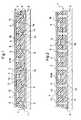
- the figure 3corresponds to a partial view from above of a part of a de-icing system of the figure 1 which more particularly shows the first layer 1a and the wiring 10.
- the cells 5have a hexagonal shape.
- the first layer 1athus has hexagonal elements 11 in the form of enhancements, each having a central portion 12 on substantially circular delimiting the bottom of the corresponding housing 4.
- the hexagonal elements 11are interconnected by the connecting bridges 7 of elastomer.
- the free spaces 1eare intended to be filled by the resin 6 and the first layer 1a with the connecting bridges 7 which allows to substantially reduce the tensions exerted on the wiring 10 deposited on said first layer 1a.
- the figure 4is another partial view from above of a part of a de-icing system from the figure 1 .
- the figure 4shows complementary hexagonal elements 13 identical to the hexagonal elements 11. These complementary hexagonal elements 13 are deposited, if necessary glued, on the hexagonal elements 11 so as to delimit the periphery of the housings 4. For this purpose the complementary hexagonal elements 13 have a central opening through and circular to be engaged on the central parts on high 12.
- the complementary hexagonal elements 13therefore constitute the second layer 1b elastomer.
- the elastomer layer 1can therefore be likened to a honeycomb structure with two layers 1a, 1b superimposed.
- the complementary hexagonal elements 13provide on the one hand a preload of the piezoelectric actuator 4a of the ceramic type and on the other hand the support and the protection by damping vibrations of the wiring and connections.
- the ceramic and its wiringare preferably installed before completing the assembly with a second layer 1b elastomer.
- the preferred objectiveis to create substantially isotropic waves and at least parallel to the surface on which one comes to place the piezoelectric actuators 4a.
- the cells 5could also have a different shape, for example rectangular or triangular without departing from the scope of the invention.
- the figure 5is a partial view from above of an enlarged detail of the deicing system according to the invention.
- the deicing system according to the inventioncomprises different types of cells 5.
- Some cells 5 'thusdo not have a piezoelectric actuator and thus constitute inactive cells. These cells with no piezoelectric actuator are used only as resonance cavities which function only when the neighboring active cells are functioning. This may correspond for example to areas where it is known that the ice can not form, at least not critically, or that it is easily detached, or that the waves are transmitted well.
- the deicing systemit is conceivable to use an electrically conductive leading edge 3 and a conductive adhesive at the interface of said leading edge 3 and piezoelectric actuators.
- the leading edge 3can thus constitute the common electrical ground for all or part of the piezoelectric actuators 4a. This substantially reduces the on-board wiring weight 10.
- the piezoelectric actuatorscan be likened to capacitive loads. By separating said actuators into distinct blocks, each block can also be likened to a capacitive load. A block can thus be electrically charged and then discharge into another block. Part of the electrical energy involved could thus be recovered and saved.
- leading edge 3is also bonded to the second layer 1b of the elastomeric structure 1 with which it is in contact.
- the deicing systemalso extends under an outer wall of the wing, not shown, which has no leading edge 3. It is thus possible to protect at least a portion of the intrados against the formation of ice.
- the figure 6is a top view of a blade 14 for helicopter main rotor comprising a deicing system according to the invention.
- the wiring 10is performed on the wing or by separate zones in a transverse direction A when the leading edge 3 has a separate portion for each of the zones a, b, c, d , e, globally in a longitudinal direction B on a single zone when the leading edge 3 is in one piece on this zone.
- the leading edge 3is in one or more parts so as to cover a continuous zone or discontinuous zones of the wing.
- the figure 7is thus a cross-sectional view of an exemplary embodiment of the blade 14 of the figure 6 , comprising a deicing system according to the invention, associated with a leading edge 3 in one part.
- a deicing systemaccording to the invention
- Each of the zones a, b, c, d, ecan thus be provided with such a leading edge 3.
- the figure 8is a cross-sectional view of another embodiment of the blade 14 of the figure 6 , comprising a deicing system according to the invention associated with a leading edge 3 in two distinct parts.
- Each separate portion of the leading edge 3comprises for example a defrosting system.
- Each of the zones a, b, c, d, ecan thus be provided with a leading edge 3 of this type.
- the piezoelectric actuators 4aconsist of ceramic elements having a substantially cylindrical shape of the disk type.
- An electrode connected to the top and another electrode connected below the ceramic elementsmake it possible to connect said elements to the overall wiring.
- the lattercomprises for example transmission lines associated with appropriate connectors.
- the circular shape of the ceramic elements constituting the electric actuatorsmakes it possible to obtain an isotropic propagation of the ultrasonic waves in at least one plane parallel to the outer surface of the wing and in particular to the leading edge 3.
- the piezoelectric actuators 4aare installed with the wiring 10, and the second layer 1b with the interposition of a glue film. Then positioned on the whole, the leading edge 3 with the interposition of a film of adhesive at least at the actuators.
- the assembly thus producedis then attached to the structure of the blade and the resin 6 is injected into the free spaces 1e so that the resin 6 ensures by bonding a mechanical connection between the leading edge 3, the structure of the maintaining 1 and the structure of the blade.
- the fastening means of the leading edge 3comprise flexible fastening elements 15 integral with the base structure 2 and made of a material of the neoprene or silicone type.
- the ends of the leading edge 3are fixed by gluing on these flexible fastening elements 15.
- the basic structure 2 of the blade 14has, facing the leading edge 3, a clearance of material 16 so as to define a free gap 17 in which piezoelectric actuators are arranged.
- Such an assemblymakes it possible to mount the leading edge 3 according to a so-called floating configuration.
- the flexible fastening elements 15are advantageously covered by the leading edge 3 so as to avoid abrasion of said flexible fastening elements 15.
- the holding structure 1consists of a set of individual blocks 18 each comprising a piezoelectric element 4a at least partially embedded in a material of said individual blocks which serves as prestressing.
- the spaces located between the individual blocks 18are filled with resin 6 and the leading edge 3 is advantageously bonded to the free surfaces of the piezoelectric elements 4a.
- each individual block 18is advantageously constituted by a lower part 18a and an upper part 18b open facing the leading edge 3.
- the connectorcomprises connection wires 19,20 connecting each piezoelectric element 4a to a connection harness 21 bonded via bonding zones 22 to the base structure 2.
- connection wires 19,20connecting each piezoelectric element 4a to a connection harness 21 bonded via bonding zones 22 to the base structure 2.
- the deicing system according to the inventionmakes it possible, for example, to generate an ultrasonic wave whose frequency is preferably between 5 Hz and 100 kHz, through a medium consisting of the leading edge 3 and frost or ice or dust.
- the piezoelectric actuatorswill create shear stress at the interface of leading edge 3 and frost or ice, greater than 1.5 MPa, corresponding to the average shearing force of ice on a surface metal (aluminum, titanium, steel and others).
Landscapes
- Engineering & Computer Science (AREA)
- Mechanical Engineering (AREA)
- Aviation & Aerospace Engineering (AREA)
- General Electrical Machinery Utilizing Piezoelectricity, Electrostriction Or Magnetostriction (AREA)
Description
Translated fromFrenchLa présente invention se rapporte au domaine technique général du dégivrage de structures d'un aéronef et notamment des voilures fixes ou tournantes.The present invention relates to the general technical field of defrosting structures of an aircraft and in particular fixed or rotating wings.
L'invention concerne plus particulièrement le dégivrage par ultrasons, c'est-à-dire la transmission de vibrations mécaniques ultrasonores sur une structure à dégivrer et/ou le cas échéant à nettoyer. En plus du givre, les structures précitées peuvent également être recouvertes d'un dépôt de poussières qu'il convient d'éliminer.The invention relates more particularly to ultrasonic deicing, that is to say the transmission of ultrasonic mechanical vibrations on a structure to de-ice and / or where appropriate to clean. In addition to frost, the aforementioned structures can also be covered with a dust deposit that should be removed.
La présente invention fera référence principalement à des aéronefs du genre giravions, et notamment des hélicoptères, mais elle trouve son application avec tous types d'aéronefs à voilure fixe ou tournante.The present invention will refer mainly to aircraft of the genus rotorcraft, including helicopters, but it finds application with all types of aircraft fixed or rotary wing.
Il existe déjà différentes technologies de dégivreurs. On connaît ainsi les dégivreurs électrothermiques utilisés sur les hélicoptères. Ces dégivreurs comportent des résistances électriques noyées dans le bord d'attaque des pales. Les résistances électriques transforment par effet Joule l'énergie électrique qui leur est fournie en chaleur. Cette chaleur permet d'élever la température du bord d'attaque au-delà des températures favorables à la formation de givre.There are already different de-icer technologies. Electrothermal deicers used on helicopters are thus known. These deicers include electrical resistors embedded in the leading edge of the blades. The electric resistances transform by Joule effect the electrical energy which is supplied to them in heat. This heat makes it possible to raise the temperature of the leading edge beyond the temperatures favorable to the formation of frost.
Ces dégivreurs présentent cependant un certain nombre d'inconvénients en particulier pour l'application aux giravions du genre hélicoptères. En effet, ces dégivreurs consomment une puissance électrique élevée, par exemple comprise entre 10 et 40 kW. Ces dégivreurs sont aussi lourds et volumineux, en raison de la puissance électrique élevée qui est nécessaire à leur fonctionnement. Ces dégivreurs ne peuvent pas, dans ces conditions, être installés sur des petites machines. En outre, ces dégivreurs nécessitent l'utilisation d'un collecteur à balais comportant de nombreuses pistes électriques. Ces dégivreurs constituent donc des systèmes complexes et très coûteux.These deicers, however, have a number of disadvantages, particularly for application to rotorcraft type helicopters. Indeed, these defrosters consume a high electrical power, for example between 10 and 40 kW. These defrosters are also heavy and bulky, because of the high electric power that is necessary for their operation. These de-icers can not, under these conditions, be installed on small machines. In addition, these De-icers require the use of a brush manifold with many electrical tracks. These de-icers are therefore complex and very expensive systems.
Ces dégivreurs sont aussi plus lourds, à cause de la partie commande, c'est à dire l'ensemble de l'électronique de pilotage résidant en référentiel non tournant.These deicers are also heavier, because of the control part, ie all the control electronics residing in non-rotating reference.
Par ailleurs, ces dégivreurs peuvent conduire en cas de dérive de la commande électrothermique, à une dérive en température et par conséquent à un délaminage du bord d'attaque. Il est bien entendu possible de répondre à ce problème en utilisant un dispositif de protection thermique noyé dans la pale. Un tel dispositif de protection supplémentaire augmente substantiellement le coût du dégivreur ainsi que la masse embarquée, ce qui n'est pas souhaitable.Furthermore, these deicers can lead in case of drift of the electrothermal control, a temperature drift and therefore a delamination of the leading edge. It is of course possible to respond to this problem by using a thermal protection device embedded in the blade. Such an additional protective device substantially increases the cost of the de-icer as well as the onboard weight, which is undesirable.
Il a aussi été proposé par le document
De telles modalités d'implantation des moyens générateurs de vibrations sur le bord d'attaque ne sont pas satisfaisantes, notamment en raison d'un maintien douteux des moyens générateurs de vibrations dans les logements qui les reçoivent et d'une fragilisation du revêtement acoustique pouvant conduire à son délaminage.Such methods of implantation of the vibration generating means on the leading edge are unsatisfactory, in particular because of a doubtful maintenance of the vibration generating means in the housing units which receive and embrittlement of the acoustic coating may lead to delamination.
On connaît également des dégivreurs à ultrasons pour procéder au dégivrage d'une structure en cisaillant la glace grâce aux dits ultrasons. Un exemple de principe général de fonctionnement de tels dégivreurs est par exemple décrit dans le document
Ces dégivreurs, par exemple à base d'éléments céramiques, présentent l'inconvénient de ne pas pouvoir être intégrés dans des structures du genre bord d'attaque de pales d'hélicoptère. En effet, les bords d'attaque sont en général fixés mécaniquement de manière très rigide et intégralement sur une structure de base et les colles assurant le maintien desdits bords d'attaque verrouilleraient les éléments vibrants, les empêchant ainsi de transmettre leur énergie. La disposition des dégivreurs au voisinage des surfaces à dégivrer est également problématique du fait d'un manque d'espace disponible sous le bord d'attaque.These deicers, for example based on ceramic elements, have the disadvantage of not being able to be integrated in structures like the leading edge of helicopter blades. Indeed, the leading edges are generally mechanically fixed very rigidly and integrally on a base structure and the adhesives ensuring the maintenance of said leading edges lock the vibrating elements, thus preventing them from transmitting their energy. The arrangement of the de-icers in the vicinity of the surfaces to be de-iced is also problematic because of a lack of available space under the leading edge.
Un autre inconvénient des dégivreurs à ultrasons est lié à leur intégration dans des pales. Les câblages volants, induits pour la connexion de ces actionneurs, vont créer des volumes d'air non contrôlés ainsi que des zones où la colle ou la résine n'aura pas polymérisé. Des parties exothermiques peuvent également apparaître lors de la fabrication des pales.Another disadvantage of ultrasonic deicers is related to their integration in blades. Flying wirings, induced for the connection of these actuators, will create uncontrolled air volumes as well as areas where the glue or resin will not have polymerized. Exothermic parts may also appear during the manufacture of the blades.
Tous ces inconvénients augmentent le risque de perte du bord d'attaque en vol, constituant une situation catastrophique pour l'hélicoptère.All these disadvantages increase the risk of loss of the leading edge in flight, constituting a catastrophic situation for the helicopter.
Par ailleurs, il faut noter que les éléments céramiques utilisés dans les dégivreurs à ultrasons connus, doivent être précontraints.Furthermore, it should be noted that the ceramic elements used in known ultrasonic deicers must be prestressed.
On précontraint les céramiques pour les protéger vis-à-vis de certains efforts auxquels elles sont particulièrement sensibles (efforts de type torsion et de manière générale tout ce qui est en dehors de ces axes principaux). De plus la précontrainte leur permet de ne pas dépasser leurs limites mécaniques en fonctionnement, qui peuvent endommager les céramiques si lesdites limites étaient dépassées.Ceramics are prestressed to protect them against certain efforts to which they are particularly sensitive (torsion type forces and in general anything that is outside these main axes). In addition the prestressing allows them not to exceed their mechanical limits in operation, which can damage the ceramics if said limits were exceeded.
La présente invention a pour alors objet de proposer un nouveau système de dégivrage permettant de s'affranchir des limitations mentionnées.The present invention is then intended to propose a new de-icing system to overcome the limitations mentioned.
L'objet de la présente invention vise par conséquent à intégrer un système de dégivrage à ultrasons dans une voilure, par exemple une pale de rotor, sans pour autant fragiliser la fixation d'un bord d'attaque.The object of the present invention is therefore to integrate an ultrasonic deicing system in a wing, for example a rotor blade, without weakening the attachment of a leading edge.
Un autre objet de la présente invention vise à proposer un nouveau système de dégivrage permettant de simplifier les opérations d'intégration dudit système dans une structure du genre pale de rotor principal ou dans une voilure fixe.Another object of the present invention is to propose a new de-icing system for simplifying the integration operations of said system in a structure of the main rotor blade type or in a fixed wing.
Un autre objet de la présente invention vise à proposer un nouveau système de dégivrage permettant de diminuer sensiblement la masse embarquée correspondante et son coût.Another object of the present invention is to propose a new de-icing system for substantially reducing the corresponding onboard weight and its cost.
Les objets assignés à l'invention sont atteints à l'aide d'un système de dégivrage équipant un élément de voilure fixe ou tournante d'aéronef et comportant des moyens pour générer des ultrasons lesquels sont transmis au moins localement à une surface externe de l'élément de voilure. L'élément de voilure comporte une structure de base recouverte au moins localement avec au moins un bord d'attaque.The objects assigned to the invention are achieved by means of a deicing system equipping a fixed or rotating aircraft wing element and comprising means for generating ultrasound which are transmitted at least locally to an external surface of the aircraft. wing element. The wing element has a basic structure covered at least locally with at least one leading edge.
Les moyens pour générer des ultrasons sont disposés dans des logements ouverts en direction du bord d'attaque pour générer des ondes ultrasonores dont la propagation selon au moins une direction s'effectue sensiblement parallèlement à la surface externe de la voilure. Un câblage relie les moyens pour générer des ultrasons à une unité de commande et d'alimentation électrique. Des moyens de fixation fixent le bord d'attaque à la structure de base.The means for generating ultrasound are disposed in housings open towards the leading edge to generate ultrasonic waves whose propagation in at least one direction is substantially parallel to the outer surface of the wing. A wiring connects the means for generating ultrasound to a control and power supply unit. Fastening means secures the leading edge to the base structure.
Selon la présente invention, l'élément de voilure est caractérisé en ce que lesdits moyens pour générer des ultrasons sont constitués d'actionneurs piézoélectriques. L'élément de voilure comporte une structure de maintien desdits actionneurs piézoélectriques. La structure de maintien est disposée et immobilisée entre la structure de base et le bord d'attaque. La structure de maintien comporte des cellules et est ajourée pour comprendre des espaces libres entre lesdites cellules. Chaque cellule délimite un dit logement et lesdits actionneurs piézoélectriques sont disposés dans au moins un certain nombre de logements. Lesdits moyens de fixation fixent le bord d'attaque auxdits actionneurs piézoélectriques disposés dans leurs logements respectifs.According to the present invention, the wing element is characterized in that said means for generating ultrasound consist of piezoelectric actuators. The wing element comprises a structure for holding said piezoelectric actuators. The holding structure is disposed and immobilized between the base structure and the leading edge. The holding structure comprises cells and is perforated to include free spaces between said cells. Each cell defines a said housing and said piezoelectric actuators are arranged in at least a number of housing. Said fixing means fix the leading edge to said piezoelectric actuators arranged in their respective housings.
Les espaces libres traversent par exemple de part en part la structure de maintien en étant ouvert vers le bord d'attaque et vers la structure de base, alors que les logements sont borgnes en étant ouvert uniquement vers le bord d'attaque et non pas vers la structure de base.The free spaces cross for example through the holding structure being open towards the leading edge and towards the basic structure, while the housings are blind, being open only to the leading edge and not to the leading edge. the basic structure.
Par suite, on peut noyer la structure de maintien dans une résine polymérisable en disposant ladite résine notamment dans les espaces libres.As a result, it is possible to drown the holding structure in a polymerizable resin by disposing said resin in particular in the free spaces.
Selon un exemple de réalisation conforme à l'invention, la structure de maintien est en élastomère.According to an exemplary embodiment according to the invention, the holding structure is made of elastomer.
La structure de maintien est avantageusement réalisée avec un matériau pouvant réaliser une précontrainte sur les éléments piézoélectriques. Ceci est particulièrement le cas pour l'élastomère. Dès lors, la structure de maintien est précontrainte pour exercer des efforts sur les éléments piézoélectriques.The holding structure is advantageously made of a material capable of prestressing on the piezoelectric elements. This is particularly the case for the elastomer. Therefore, the holding structure is prestressed to exert efforts on the piezoelectric elements.
Selon un exemple de réalisation conforme à l'invention, la structure de maintien, la structure de base et le bord d'attaque sont solidarisés à l'aide d'une résine polymérisable. Par exemple, la résine polymérisable est disposée dans les espaces vides, entre la structure de maintien et la structure de base, et entre la structure de maintien et le bord d'attaque.According to an exemplary embodiment according to the invention, the holding structure, the base structure and the leading edge are secured with a polymerizable resin. For example, the polymerizable resin is disposed in the voids, between the holding structure and the base structure, and between the holding structure and the leading edge.
Selon un exemple de réalisation conforme à l'invention, la structure en élastomère définit des cellules comportant chacune un logement destiné à loger un actionneur piézoélectrique. Les actionneurs piézoélectriques sont par exemple collés dans les logements voire au bord d'attaque.According to an exemplary embodiment according to the invention, the elastomeric structure defines cells each comprising a housing for housing a piezoelectric actuator. The piezoelectric actuators are for example glued in the housing or at the leading edge.
Selon un exemple de réalisation conforme à l'invention, la structure en élastomère comprend une première couche ajourée solidaire de la structure de base par l'intermédiaire de la résine polymérisable et une seconde couche ajourée solidaire de la première couche par l'intermédiaire d'un moyen de liaison du type film de colle, les logements pour les actionneurs piézoélectriques étant prévus dans ladite seconde couche. La résine peut aussi contribuer à la solidarisation des deux couches.According to an exemplary embodiment according to the invention, the elastomer structure comprises a first perforated layer integral with the base structure via the polymerizable resin and a second perforated layer secured to the first layer via bonding means of the adhesive film type, the housings for the piezoelectric actuators being provided in said second layer. The resin can also contribute to the joining of the two layers.
Selon un exemple de réalisation conforme à l'invention, les cellules sont indépendantes et reliées entre elles par la résine polymérisable et par le bord d'attaque.According to an exemplary embodiment according to the invention, the cells are independent and interconnected by the polymerizable resin and the leading edge.
Selon un exemple de réalisation conforme à l'invention, les cellules sont reliées entre elles au niveau de la première couche d'élastomère, par des ponts de liaison en élastomère faisant partie intégrante de ladite première couche.According to an exemplary embodiment according to the invention, the cells are interconnected at the level of the first elastomer layer, by elastomeric connecting bridges forming an integral part of said first layer.
Selon un exemple de réalisation conforme à l'invention, les cellules présentent une forme hexagonale.According to an exemplary embodiment according to the invention, the cells have a hexagonal shape.
Selon un exemple de réalisation conforme à l'invention, des espaces libres subsistant entre les cellules sont remplis avec la résine polymérisable.According to an exemplary embodiment according to the invention, free spaces remaining between the cells are filled with the polymerizable resin.
Selon un exemple de réalisation conforme à l'invention, le bord d'attaque présente sur sa face intérieure des plots en saillie, engagés dans la résine polymérisable contenue dans des espaces libres.According to an exemplary embodiment according to the invention, the leading edge has on its inner face protruding studs engaged in the polymerizable resin contained in free spaces.
Selon un exemple de réalisation conforme à l'invention, le bord d'attaque est en une ou en plusieurs parties de manière à recouvrir une zone continue ou des zones discontinues de la voilure.According to an exemplary embodiment according to the invention, the leading edge is in one or more parts so as to cover a continuous zone or discontinuous areas of the wing.
Selon un exemple de réalisation conforme à l'invention, les moyens de fixation du bord d'attaque sont des moyens de collage réalisant une liaison par collage avec les actionneurs piézoélectriques disposés dans leurs logements respectifs.According to an exemplary embodiment according to the invention, the fastening means of the leading edge are bonding means forming a connection by bonding with the piezoelectric actuators arranged in their respective housings.
Selon un exemple de réalisation conforme à l'invention, le bord d'attaque est également collé sur la seconde couche de la structure en élastomère avec laquelle il est en contact.According to an exemplary embodiment according to the invention, the leading edge is also bonded to the second layer of the elastomeric structure with which it is in contact.
Selon un autre exemple de réalisation conforme à l'invention, les moyens de fixation du bord d'attaque comprennent des éléments de fixation souple solidaires de la structure de base et réalisés avec un matériau du genre néoprène ou silicone, sur lesquels sont fixées par collage les extrémités du bord d'attaque, la structure de base présentant au regard du bord d'attaque un dégagement de matière de manière à délimiter un intervalle libre dans lequel sont disposés des actionneurs piézoélectriques.According to another exemplary embodiment according to the invention, the fastening means of the leading edge comprise flexible fastening elements integral with the base structure and made of a material of the neoprene or silicone type, to which are fixed by gluing. the ends of the leading edge, the basic structure having a clearance of material facing the leading edge so as to define a free gap in which are arranged piezoelectric actuators.
Selon un exemple de réalisation conforme à l'invention, le système de dégivrage s'étend également sous une paroi extérieure de la voilure qui est dépourvue de bord d'attaque. Une telle solution est avantageuse dans la mesure où une partie de la captation du givre se fait sur l'intrados et entraine dans une moindre mesure des pertes de performances. Il peut donc être intéressant d'étendre le système de protection à cette zone.According to an exemplary embodiment according to the invention, the deicing system also extends under an outer wall of the wing which is devoid of leading edge. Such a solution is advantageous insofar as part of the capture of frost is on the lower surface and leads to a lesser loss of performance. It may therefore be interesting to extend the protection system to this area.
Selon un exemple de réalisation conforme à l'invention, le câblage est effectué sur la voilure soit par zones distinctes lorsque le bord d'attaque comporte une partie distincte pour chacune des zones, soit de façon globale sur une zone unique lorsque le bord d'attaque est en un seul tenant sur cette zone. Cela permet de piloter le système différemment. Un câblage global entraine une mise en fonctionnement de l'ensemble du système alors qu'il est peut être intéressant de gérer le dégivrage par zones dans le temps. Cette solution est particulièrement avantageuse si la consommation du système global est trop importante.According to an exemplary embodiment according to the invention, the wiring is performed on the wing or by separate areas when the leading edge has a separate portion for each of the zones, or globally on a single zone when the edge of Attack is in one piece on this area. This allows to control the system differently. A global wiring leads to an operation of the entire system while it may be interesting to manage the defrost by zones in time. This solution is particularly advantageous if the consumption of the overall system is too important.
Selon un exemple de réalisation conforme à l'invention, les actionneurs piézoélectriques sont constitués d'éléments céramiques présentant une forme sensiblement cylindrique du genre disque. On obtient ainsi une propagation des ondes ultrasonores sensiblement isotrope dans un plan parallèle à la surface extérieure de la voilure.According to an exemplary embodiment according to the invention, the piezoelectric actuators consist of ceramic elements having a substantially cylindrical shape of the disk type. This results in a propagation of substantially isotropic ultrasound waves in a plane parallel to the outer surface of the wing.
Alternativement, si l'on recherche une propagation plus marquée dans une ou plusieurs directions, il est possible d'utiliser des éléments céramiques de forme différente.Alternatively, if one seeks a more pronounced propagation in one or more directions, it is possible to use ceramic elements of different shape.
Les objets assignés à l'invention sont également atteints à l'aide d'une pale de rotor principal pour giravion comportant un système de dégivrage conformément à l'invention.The objects assigned to the invention are also achieved by means of a rotorcraft main rotor blade comprising a de-icing system according to the invention.
Les objets assignés à l'invention sont également atteints à l'aide d'un élément mobile d'une voilure fixe d'aéronef du genre volet comportant un système de dégivrage conformément à l'invention.The objects assigned to the invention are also achieved by means of a movable member of a fixed wing of the wing type aircraft comprising a deicing system according to the invention.
Le système de dégivrage conforme à l'invention présente l'avantage d'être économe sur le plan de la puissance électrique consommée. En outre, le système ne présente pas de risques d'apparition d'échauffements localisés qui sont préjudiciables à la cohésion mécanique de la voilure.The deicing system according to the invention has the advantage of being economical in terms of the electrical power consumed. In addition, the system does not present risks of occurrence of localized heating which are detrimental to the mechanical cohesion of the wing.
Le système de dégivrage conforme à l'invention présente également un encombrement réduit et une masse embarquée réduite, notamment par l'optimisation du câblage et des moyens de commande associés. L'organisation du câblage par exemple selon une conception matricielle permet de s'adapter au mieux à la forme des cavités logeant les actionneurs. Un tel câblage permet de sélectionner un ou plusieurs actionneurs piézoélectriques à des fins d'alimentation. Un tel câblage permet de réduire la quantité de câbles par rapport à une connectique individuelle de chaque actionneur piézoélectrique.The deicing system according to the invention also has a small footprint and a reduced onboard weight, in particular by optimizing the wiring and associated control means. The organization of the cabling for example according to a matrix design makes it possible to better adapt to the shape of the cavities housing the actuators. Such wiring allows one or more piezoelectric actuators to be selected for power purposes. Such wiring reduces the amount of cables compared to an individual connector of each piezoelectric actuator.
Un autre avantage du système de dégivrage conforme à l'invention réside dans le fait qu'une défaillance d'un ou de plusieurs actionneurs piézoélectriques n'altère pas l'efficacité du système de dégivrage dans son ensemble. On peut en effet définir un pourcentage d'actionneurs défaillants en deçà duquel l'efficacité du dégivrage n'est pas affectée.Another advantage of the deicing system according to the invention lies in the fact that a failure of one or more piezoelectric actuators does not affect the efficiency of the deicing system as a whole. We can indeed define a percentage of failing actuators below which deicing efficiency is not affected.
Contrairement aux attentes, il est remarquable de constater que le bord d'attaque, ne doit pas être collé intégralement sur une surface porteuse et que la libération d'un certain pourcentage de sa surface n'est pas préjudiciable à la solidité de sa fixation. Selon un exemple de réalisation, ce pourcentage peut atteindre au moins 30%.Contrary to expectations, it is remarkable to note that the leading edge, must not be glued integrally on a bearing surface and that the release of a certain percentage of its surface is not detrimental to the strength of its fixation. According to an exemplary embodiment, this percentage can reach at least 30%.
L'invention présente également un avantage au niveau de la maintenance grâce à un démontage facilité.The invention also has an advantage in maintenance through easy disassembly.
L'invention et ses avantages apparaîtront avec plus de détails dans le cadre de la description qui suit avec un exemple de réalisation donné à titre illustratif en référence aux figures annexées qui représentent :
- la
figure 1 , une vue en coupe d'un exemple de réalisation d'un système de dégivrage conforme à l'invention, intégré dans un élément de voilure d'aéronef, - la
figure 2 , une vue en coupe d'un autre exemple de réalisation d'un système de dégivrage conforme à l'invention, intégré dans un élément de voilure d'aéronef, - la
figure 3 , une vue partielle de dessus d'une partie d'un système de dégivrage de lafigure 1 , - la
figure 4 , une autre vue partielle de dessus d'une partie d'un système de dégivrage de lafigure 1 , - la
figure 5 , une vue partielle de dessus d'un détail agrandi du système de dégivrage conforme à l'invention, - la
figure 6 , une vue de dessus d'une pale pour rotor principal d'hélicoptère comportant un système de dégivrage conforme à l'invention, - la
figure 7 , une vue en coupe transversale d'un exemple de réalisation de la pale de lafigure 6 , comportant un système de dégivrage conforme à l'invention, - la
figure 8 , une vue en coupe transversale d'un autre exemple de réalisation de la pale de lafigure 6 , comportant un système de dégivrage conforme à l'invention, - la
figure 9 , une vue en coupe transversale d'un autre exemple de réalisation d'une pale comportant un système de dégivrage conforme à l'invention, - et la
figure 10 , une vue en coupe d'un exemple de réalisation supplémentaire d'un système de dégivrage conforme à l'invention, intégré dans un élément de voilure d'aéronef.
- the
figure 1 , a sectional view of an exemplary embodiment of a deicing system according to the invention integrated in an aircraft wing element, - the
figure 2 , a sectional view of another embodiment of a deicing system according to the invention integrated in an aircraft wing element, - the
figure 3 , a partial view from above of a part of a de-icing system of thefigure 1 , - the
figure 4 , another partial view from above of a part of a de-icing system of thefigure 1 , - the
figure 5 , a partial view from above of an enlarged detail of the deicing system according to the invention, - the
figure 6 , a top view of a helicopter main rotor blade comprising a deicing system according to the invention, - the
figure 7 , a cross-sectional view of an exemplary embodiment of the blade of thefigure 6 , comprising a deicing system according to the invention, - the
figure 8 , a cross-sectional view of another embodiment of the blade of thefigure 6 , comprising a deicing system according to the invention, - the
figure 9 , a cross-sectional view of another embodiment of a blade comprising a deicing system according to the invention, - and the
figure 10 , a sectional view of an additional embodiment of a deicing system according to the invention, integrated into an aircraft wing element.
Les éléments structurellement et fonctionnellement identiques, présents sur plusieurs figures distinctes, sont affectés d'une seule et même référence numérique ou alphanumérique.The structurally and functionally identical elements, present in several distinct figures, are assigned a single numerical or alphanumeric reference.
La
Le système de dégivrage comporte une structure de maintien en élastomère 1 ajourée, disposée et immobilisée entre une structure de base 2 et un bord d'attaque 3. La structure de base 2 est avantageusement une structure à base de fibres longitudinales du groupe des matériaux composites.The defrosting system comprises a perforated elastomer holding structure 1, arranged and immobilized between a
Des logements 4 sont délimités dans la structure en élastomère 1 et ouverts en direction du bord d'attaque 3.
Selon un exemple de réalisation conforme à l'invention, la structure de maintien en élastomère 1 définit des cellules 5 individualisées comportant chacune un logement 4 et pour y loger un actionneur piézoélectrique 4a.According to an exemplary embodiment according to the invention, the elastomeric holding structure 1 defines
Avantageusement, des actionneurs piézoélectriques sont disposés dans au moins un certain nombre de logements 4 pour générer des ultrasons.Advantageously, piezoelectric actuators are arranged in at least a number of
Selon un exemple de réalisation conforme à l'invention, la structure en élastomère 1, la structure de base 2 et le bord d'attaque 3 sont solidarisés ensembles à l'aide d'une résine polymérisable 6.According to an exemplary embodiment according to the invention, the elastomer structure 1, the
La structure en élastomère 1 comprend par exemple une première couche 1a ajourée solidaire de la structure de base 2 par l'intermédiaire d'un film de colle et une seconde couche 1b ajourée solidaire de la première couche 1a par l'intermédiaire de ladite résine 6. Les logements 4 pour les actionneurs piézoélectriques 4a sont de préférence prévus dans ladite seconde couche 1b.The elastomer structure 1 comprises, for example, a first
Selon un exemple de réalisation conforme à l'invention, les cellules 5 sont reliées entre elles au niveau de la première couche 1a d'élastomère, par des ponts de liaison 7 en élastomère faisant partie intégrante de ladite première couche 1a.According to an exemplary embodiment according to the invention, the
La première couche 1a présente avantageusement des rainures 1c et 1d au niveau des interfaces des cellules 5, permettant ainsi un meilleur accrochage avec la résine 6. Ces rainures 1c,1d constituent des zones à épaisseur réduite pour obtenir une cohérence géométrique pour l'ensemble des ponts de liaison 7, d'autant qu'il est envisagé d'usiner un grand bloc de matière élastomère pour obtenir la première couche 1a. On peut aussi profiter de ces zones pour y faire passer le câblage et éviter ainsi que le câblage assure une cohésion mécanique entre différents éléments.The
Selon un autre exemple de réalisation conforme à l'invention et illustré à la
Selon un exemple de réalisation conforme à l'invention, des espaces libres 1e subsistant entre les cellules 5 sont remplis avec la résine 6 polymérisable.According to an exemplary embodiment according to the invention,
Selon un exemple de réalisation conforme à l'invention et illustré à la
Dans l'exemple de la réalisation de la
Le système de dégivrage conforme à l'invention comporte également des moyens de collage 9 pour fixer le bord d'attaque 3 sur les actionneurs piézoélectriques 4a disposés dans leurs logements 4 respectifs. Les actionneurs piézoélectriques 4a sont recouverts par exemple d'un film de colle, du genre époxy, sur leur surface en contact avec le bord d'attaque 3.The deicing system according to the invention also comprises gluing means 9 for fixing the
Un câblage 10 reliant les actionneurs piézoélectriques à une unité de commande et d'alimentation électrique est également installé de manière connue. Chaque actionneur est connecté. Les câbles sont plus ou moins noyés dans les différents élastomères pour être protégés lors de la manipulation, lors de l'installation et une fois en service. La partie commande/alimentation est déportée et ne fait pas partie intégrante de la pale. Le câblage noyé dans l'élastomère, est de ce fait protégé de certaines vibrations. Sa fiabilité est ainsi améliorée.A
La
Selon un exemple de réalisation conforme à l'invention, les cellules 5 présentent une forme hexagonale. La première couche 1a présente donc des éléments hexagonaux 11 sous forme de rehaussements, présentant chacun une partie sur élevée centrale 12 sensiblement circulaire délimitant le fond du logement 4 correspondant. Les éléments hexagonaux 11 sont reliés entre eux par les ponts de liaison 7 en élastomère.According to an exemplary embodiment according to the invention, the
Les espaces libres 1e sont destinés à être remplis par la résine 6 et la première couche 1a avec les ponts de liaison 7 ce qui permet de réduire substantiellement les tensions exercées sur le câblage 10 déposé sur ladite première couche 1 a.The
La
Les éléments hexagonaux complémentaires 13 assurent d'une part une précontrainte de l'actionneur piézoélectrique 4a du genre céramique et d'autre part le support et la protection par l'amortissement des vibrations du câblage et des connexions.The complementary
La céramique et son câblage sont installés de préférence avant de compléter l'assemblage avec une seconde couche 1b en élastomère.The ceramic and its wiring are preferably installed before completing the assembly with a
L'objectif préférentiel est de créer des ondes sensiblement isotropes et au moins parallèle à la surface sur laquelle on vient placer les actionneurs piézoélectriques 4a.The preferred objective is to create substantially isotropic waves and at least parallel to the surface on which one comes to place the
A titre de variante, les cellules 5 pourraient également présenter une forme différente, par exemple rectangulaire ou triangulaire sans sortir du cadre de l'invention.Alternatively, the
La
Certaines cellules 5' ne comportent ainsi pas d'actionneur piézoélectrique et constituent de ce fait des cellules 5 inactives. On utilise ces cellules 5 ne comportant pas d'actionneur piézoélectrique, uniquement comme cavités de résonance qui fonctionnent uniquement lorsque les cellules 5 actives voisines fonctionnent. Cela peut correspondre par exemple à des zones où l'on sait que la glace ne peut pas se former, en tout cas pas de manière critique, ou qu'elle se détache facilement, ou que les ondes se transmettent bien.Some cells 5 'thus do not have a piezoelectric actuator and thus constitute inactive cells. These cells with no piezoelectric actuator are used only as resonance cavities which function only when the neighboring active cells are functioning. This may correspond for example to areas where it is known that the ice can not form, at least not critically, or that it is easily detached, or that the waves are transmitted well.
En outre, il est possible de prévoir des moyens de remplissage 5" de type cellules ne délimitant pas un logement.In addition, it is possible to provide cell-type filling means 5 "not delimiting a housing.
Selon un exemple de réalisation du système de dégivrage conforme à l'invention, on peut envisager d'utiliser un bord d'attaque 3 conducteur électriquement ainsi qu'une colle conductrice à l'interface dudit bord d'attaque 3 et des actionneurs piézoélectriques. Le bord d'attaque 3 peut ainsi constituer la masse électrique commune pour l'ensemble ou une partie des actionneurs piézoélectriques 4a. Ceci permet de réduire substantiellement la masse embarquée de câblage 10.According to an exemplary embodiment of the deicing system according to the invention, it is conceivable to use an electrically conductive
En outre, les actionneurs piézoélectriques peuvent être assimilés à des charges capacitives. En séparant lesdits actionneurs en blocs distincts, chaque bloc peut également être assimilé à une charge capacitive. Un bloc peut ainsi se charger électriquement puis se décharger dans un autre bloc. Une partie de l'énergie électrique mise en jeu pourrait ainsi être récupérée et économisée.In addition, the piezoelectric actuators can be likened to capacitive loads. By separating said actuators into distinct blocks, each block can also be likened to a capacitive load. A block can thus be electrically charged and then discharge into another block. Part of the electrical energy involved could thus be recovered and saved.
Dans une réalisation se basant sur des zones distinctes, on pourrait ainsi activer une zone, qui emmagasinerait de l'énergie en se déformant et la restituerait en partie à la zone voisine, en revenant à sa position initiale. Il serait alors possible d'économiser une partie de l'énergie stockée et non utilisée.In an embodiment based on distinct areas, one could thus activate a zone, which would store energy by deforming and return it partially to the neighboring area, returning to its original position. It would then be possible to save some of the stored and unused energy.
Selon un autre exemple de réalisation conforme à l'invention, le bord d'attaque 3 est également collé sur la seconde couche 1b de la structure en élastomère 1 avec laquelle il est en contact.According to another embodiment of the invention, the
Selon un exemple de réalisation conforme à l'invention, le système de dégivrage s'étend également sous une paroi extérieure de la voilure, non représentée, qui est dépourvue de bord d'attaque 3. On peut ainsi protéger au moins une partie de l'intrados contre la formation de glace.According to an exemplary embodiment according to the invention, the deicing system also extends under an outer wall of the wing, not shown, which has no
La
Selon un exemple de réalisation conforme à l'invention, le câblage 10 est effectué sur la voilure soit par zones distinctes selon une direction A transversale lorsque le bord d'attaque 3 comporte une partie distincte pour chacune des zones a, b, c, d, e, soit de façon globale selon une direction B longitudinale sur une zone unique lorsque le bord d'attaque 3 est en un seul tenant sur cette zone.According to an exemplary embodiment according to the invention, the
Il s'agit de gérer localement et temporellement le dégivrage par zones (a, b, c, d, e). Le choix est à faire en fonction de la consommation de l'ensemble des actionneurs.It is a question of managing locally and temporally zone defrosting (a, b, c, d, e). The choice is to be made according to the consumption of all the actuators.
Selon un exemple de réalisation conforme à l'invention, le bord d'attaque 3 est en une ou en plusieurs parties de manière à recouvrir une zone continue ou des zones discontinues de la voilure.According to an exemplary embodiment according to the invention, the
La
La
Selon un exemple de réalisation conforme à l'invention, les actionneurs piézoélectriques 4a sont constitués d'éléments céramiques présentant une forme sensiblement cylindrique du genre disque. Une électrode connectée au dessus et une autre électrode connectée en dessous des éléments céramiques, permettent de relier lesdits éléments au câblage 10 d'ensemble. Ce dernier comprend par exemple des lignes de transmission associées à des connecteurs appropriés.According to an exemplary embodiment according to the invention, the
La forme circulaire des éléments céramiques constituant les actionneurs électriques, permet d'obtenir une propagation isotrope des ondes ultrasonores dans au moins un plan parallèle à la surface extérieure de la voilure et notamment au bord d'attaque 3.The circular shape of the ceramic elements constituting the electric actuators makes it possible to obtain an isotropic propagation of the ultrasonic waves in at least one plane parallel to the outer surface of the wing and in particular to the
Lors d'un exemple de montage du système de dégivrage conforme à l'invention, après l'installation de la première couche 1a sur un plan de travail, on installe les actionneurs piézoélectriques 4a avec le câblage 10, puis on met en place la seconde couche 1b avec l'interposition d'un film de colle. On positionne ensuite sur le tout, le bord d'attaque 3 avec l'interposition d'un film de colle au moins au niveau des actionneurs. L'ensemble ainsi réalisé est alors rapporté sur la structure de la pale et on injecte la résine 6 dans les espaces libres 1e de façon à ce que ladite résine 6 assure par collage une liaison mécanique entre le bord d'attaque 3, la structure de maintien 1 et la structure de la pale.During an example of mounting of the deicing system according to the invention, after the installation of the
Selon un exemple de réalisation illustré par la
Les éléments de fixation souples 15 sont avantageusement recouverts par le bord d'attaque 3 de manière à éviter une abrasion desdits éléments de fixation souples 15.The
Selon un autre exemple de réalisation du système de dégivrage conforme à l'invention, illustré par exemple à la
La connectique comprend des fils de connexion 19,20 reliant chaque élément piézoélectrique 4a à un harnais de connexion 21 collé via des zones de collage 22 sur la structure de base 2. Ainsi, lors du montage du système de dégivrage, il suffit de connecter chaque bloc individuel 18 sur le harnais de connexion 21 et de fixer le tout par le biais de la résine 6.The connector comprises
Le système de dégivrage conforme à l'invention permet par exemple de générer une onde ultrasonore dont la fréquence est comprise de préférence entre 5 Hz et 100 kHz, à travers un milieu constitué du bord d'attaque 3 et de givre ou de glace ou de poussières. Les actionneurs piézoélectriques vont créer une contrainte de cisaillement à l'interface du bord d'attaque 3 et du givre ou de la glace, supérieure à 1,5 MPa, correspondant à la force d'adhésion moyenne en cisaillement de la glace sur une surface métallique (aluminium, titane, acier et autres).The deicing system according to the invention makes it possible, for example, to generate an ultrasonic wave whose frequency is preferably between 5 Hz and 100 kHz, through a medium consisting of the
Naturellement, la présente invention est sujette à de nombreuses variations quant à sa mise en oeuvre. Bien que plusieurs modes de réalisations aient été décrits, on comprend bien qu'il n'est pas concevable d'identifier de manière exhaustive tous les modes possibles. Il est bien sûr envisageable de remplacer un moyen décrit par un moyen équivalent sans sortir du cadre de la présente invention défini par le texte des revendications.Naturally, the present invention is subject to many variations as to its implementation. Although several embodiments have been described, it is clear that it is not conceivable to exhaustively identify all the possible modes. It is of course conceivable to replace a means described by equivalent means without departing from the scope of the present invention defined by the text of the claims.
Claims (20)
- Fixed or rotary aircraft wing element equipped with a de-icing system comprising means for generating ultrasounds which are transmitted at least locally to an outside surface of the wing element, which element comprises a base structure (2) covered at least locally with at least one leading edge (3), the means for generating ultrasounds being arranged in housings (4) open towards the leading edge (3) in order to generate ultrasound waves which propagate in at least one direction substantially in parallel with the outside surface, wiring (10) connecting the means for generating ultrasounds to an electrical power supply and control unit, fastening means fastening the leading edge (3) to the base structure (2),characterised in that said means for generating ultrasounds are constituted by piezoelectric actuators (4a), the fastening means comprising a support structure (1) for the piezoelectric actuators (4a) on the base structure (2), the support structure (1) being arranged and immobilised between the base structure (2) and the leading edge (3) which covers the piezoelectric actuators (4a), the support structure (1) comprising cells (5) and being perforated to comprise empty spaces (1e) between said cells (5), each cell defining a said housing (4) and said piezoelectric actuators (4a) being arranged in at least a certain number of housings (4), said fastening means fastening the leading edge to said piezoelectric actuators (4a) arranged in their respective housings (4).
- Aircraft wing element according to claim 1,
characterised in that the support structure (1) is made of an elastomer. - Aircraft wing element according to claim 1,
characterised in that the support structure (1) is prestressed to exert forces on the piezoelectric actuators (4a). - Aircraft wing element according to any one of claims 1 to 3,
characterised in that the support structure (1), the base structure (2) and the leading edge (3) are secured to one another using films of adhesive. - Aircraft wing element according to claim 2,
characterised in that the elastomer support structure (1) comprises a perforated first layer (1a) secured to the base structure (2) by means of a polymerisable resin (6) and a perforated second layer (1b) secured to the first layer (1a) by a connection means of the adhesive film type, the housings (4) for the piezoelectric actuators (4a) being provided in said second layer (1b). - Aircraft wing element according to claim 1,
characterised in that the cells (5) are structurally independent and connected to one another by a polymerisable resin (6) and by the leading edge (3), said resin (6) being arranged in said empty spaces (1e). - Aircraft wing element according to claim 5,
characterised in that the cells (5) are connected to one another at the first elastomer layer (1a) by elastomer connecting bridges (7) forming an integral part of said first layer (1a). - Aircraft wing element according to any one of claims 1 to 7,
characterised in that the cells (5) have a hexagonal shape. - Aircraft wing element according to any one of claims 1 to 8,
characterised in that empty spaces (1e) remaining between the cells (5) are filled with a polymerisable resin (6). - Aircraft wing element according to claim 9,
characterised in that the leading edge (3) has projecting studs (8) on its inside face, which studs are engaged in the polymerisable resin (6) contained in empty spaces (1e). - Aircraft wing element according to any one of claims 1 to 10,
characterised in that the leading edge (3) is in one or more portions so as to cover a continuous zone or discontinuous zones of the wing. - Aircraft wing element according to any one of claims 1 to 11,
characterised in that the means for fastening the leading edge (3) are adhesive bonding means (9) providing a connection by adhesive bonding with the piezoelectric actuators (4a) arranged in their respective housings (4). - Aircraft wing element according to claim 5,
characterised in that the leading edge (3) is adhesively bonded to the second layer (1b) of the elastomer structure (1) with which it is in contact. - Aircraft wing element according to any one of claims 1 to 13,
characterised in that the piezoelectric actuators are constituted by disc-like ceramic elements having a substantially cylindrical shape. - Aircraft wing element according to any one of claims 1 to 14,
characterised in that means for fastening the leading edge (3) comprise flexible fastening elements (15) secured to the base structure (2) and made of a material of the neoprene or silicone type, to which the ends of the leading edge (3) are fastened by adhesive bonding, the base structure (2) having with regard to the leading edge (3) a material relief (16) so as to define an empty gap (17) in which piezoelectric actuators (4a) are arranged. - Aircraft wing element according to any one of claims 1 to 15,
characterised in that said de-icing system also extends under at least an outside wall portion of the wing which does not have the leading edge (3). - Aircraft wing element according to any one of claims 1 to 16,
characterised in that the wiring (10) is carried out on the wing in distinct zones when the leading edge (3) comprises a distinct portion (a,b,c,d,e) for each of the zones. - Aircraft wing element according to any one of claims 1 to 16,
characterised in that the wiring (10) is carried out on the wing overall in a single zone when the leading edge (3) is a single piece over said zone. - Main rotor blade (14) for rotorcraft comprising a wing element in accordance with any one of claims 1 to 18.
- Movable element of an aircraft fixed wing of the flap type, comprising a wing element in accordance with any one of claims 1 to 18.
Applications Claiming Priority (1)
| Application Number | Priority Date | Filing Date | Title |
|---|---|---|---|
| FR1003827AFR2965249B1 (en) | 2010-09-28 | 2010-09-28 | IMPROVED DEFROSTING SYSTEM FOR FIXED OR ROTATING SAIL OF AN AIRCRAFT |
Publications (2)
| Publication Number | Publication Date |
|---|---|
| EP2433868A1 EP2433868A1 (en) | 2012-03-28 |
| EP2433868B1true EP2433868B1 (en) | 2015-11-11 |
Family
ID=43903831
Family Applications (1)
| Application Number | Title | Priority Date | Filing Date |
|---|---|---|---|
| EP11007542.1AActiveEP2433868B1 (en) | 2010-09-28 | 2011-09-15 | Improved de-icing system for a fixed or rotary wing of an aircraft |
Country Status (3)
| Country | Link |
|---|---|
| US (1) | US8888047B2 (en) |
| EP (1) | EP2433868B1 (en) |
| FR (1) | FR2965249B1 (en) |
Cited By (1)
| Publication number | Priority date | Publication date | Assignee | Title |
|---|---|---|---|---|
| FR3135449A1 (en) | 2022-05-16 | 2023-11-17 | Pytheas Technology | Defrosting system for a mechanical part, comprising at least one piezoelectric actuator |
Families Citing this family (20)
| Publication number | Priority date | Publication date | Assignee | Title |
|---|---|---|---|---|
| JP5589826B2 (en)* | 2010-03-19 | 2014-09-17 | セイコーエプソン株式会社 | Ultrasonic sensor |
| FR2965249B1 (en)* | 2010-09-28 | 2013-03-15 | Eurocopter France | IMPROVED DEFROSTING SYSTEM FOR FIXED OR ROTATING SAIL OF AN AIRCRAFT |
| US8827207B2 (en) | 2011-05-03 | 2014-09-09 | Goodrich Corporation | Ice protection system |
| US9067685B2 (en)* | 2012-04-18 | 2015-06-30 | Zodiac Aerotechnics | De-icing systems and methods |
| GB2494766B (en) | 2012-09-11 | 2014-01-01 | Selex Es Ltd | De-Icing system and method |
| EP2816200B1 (en) | 2013-06-18 | 2017-02-01 | General Electric Technology GmbH | Method and device for suppressing the formation of ice on structures at the air intake of a turbomachine |
| JP2016524089A (en)* | 2013-06-28 | 2016-08-12 | ゼネラル・エレクトリック・カンパニイ | Composite piezoelectric application system and method for ice detachment |
| US10124772B1 (en) | 2013-10-18 | 2018-11-13 | Todd James Hartman | Systems, methods, and apparatus for debris removal |
| DE102013020496A1 (en)* | 2013-12-11 | 2015-06-11 | Airbus Defence and Space GmbH | Actuator mounting method and manufacturing method for an ice protection device and mounting device |
| CN105966626B (en)* | 2016-05-23 | 2018-01-02 | 北京航空航天大学 | A kind of new lifting airscrew hot gas expanded film and electric heating joint prevents/deicer |
| GB2550947B (en)* | 2016-05-26 | 2021-07-21 | Bae Systems Plc | De-icing system |
| EP3546364A1 (en)* | 2018-03-28 | 2019-10-02 | Ratier-Figeac SAS | De-icing apparatus |
| CN109436338B (en)* | 2018-10-31 | 2022-05-06 | 浙江清华柔性电子技术研究院 | Anti-icing device and anti-icing control method based on the device |
| CN110816855B (en)* | 2019-10-31 | 2021-06-25 | 清华大学 | An aircraft wing anti-icing device and method based on ultrasonic vibration |
| US20230242261A1 (en)* | 2022-01-28 | 2023-08-03 | Meggitt Aerospace Limited | Piezo de-icing and anti-icing systems and methods |
| CN116892490B (en)* | 2023-09-08 | 2023-11-28 | 中北大学 | Ultrasonic deicing method, controller, system and medium for wind driven generator blade |
| US12371173B1 (en) | 2024-01-17 | 2025-07-29 | Goodrich Corporation | Sustainable hybrid piezoelectric matrix ice protection system |
| EP4588804A1 (en)* | 2024-01-17 | 2025-07-23 | Goodrich Corporation | Sustainable hybrid piezoelectric matrix ice protection system |
| EP4592185A1 (en)* | 2024-01-24 | 2025-07-30 | Goodrich Corporation | Hybrid ice protection system |
| US20250236400A1 (en)* | 2024-01-24 | 2025-07-24 | Goodrich Corporation | Low frequency piezoelectric matrix de-icing system |
Family Cites Families (26)
| Publication number | Priority date | Publication date | Assignee | Title |
|---|---|---|---|---|
| US3809341A (en)* | 1972-11-14 | 1974-05-07 | I Levin | Device for removing ice from surfaces of thin-walled structures |
| US4277711A (en)* | 1979-10-11 | 1981-07-07 | Hewlett-Packard Company | Acoustic electric transducer with shield of controlled thickness |
| US4277712A (en)* | 1979-10-11 | 1981-07-07 | Hewlett-Packard Company | Acoustic electric transducer with slotted base |
| US4385255A (en)* | 1979-11-02 | 1983-05-24 | Yokogawa Electric Works, Ltd. | Linear array ultrasonic transducer |
| US4545553A (en)* | 1983-02-25 | 1985-10-08 | The United States Of America As Represented By The United States National Aeronautics And Space Administration | Piezoelectric deicing device |
| US4704556A (en)* | 1983-12-05 | 1987-11-03 | Leslie Kay | Transducers |
| US4732351A (en)* | 1985-03-21 | 1988-03-22 | Larry Bird | Anti-icing and deicing device |
| US4690353A (en)* | 1985-05-31 | 1987-09-01 | The United States Of America As Represented By The Administrator Of The National Aeronautics And Space Administration | Electro-expulsive separation system |
| US5744898A (en)* | 1992-05-14 | 1998-04-28 | Duke University | Ultrasound transducer array with transmitter/receiver integrated circuitry |
| US5376859A (en)* | 1994-02-07 | 1994-12-27 | The United States Of America As Represented By The Secretary Of The Navy | Transducers with improved signal transfer |
| US5655276A (en)* | 1995-02-06 | 1997-08-12 | General Electric Company | Method of manufacturing two-dimensional array ultrasonic transducers |
| JP2001326999A (en)* | 2000-05-18 | 2001-11-22 | Olympus Optical Co Ltd | Method for machining piezoelectric structure, and production method of complex piezoelectric body |
| EP1616525A3 (en)* | 2002-07-19 | 2006-02-01 | Aloka Co., Ltd. | Ultrasonic probe |
| US7382082B2 (en)* | 2002-08-14 | 2008-06-03 | Bhardwaj Mahesh C | Piezoelectric transducer with gas matrix |
| EP1738407B1 (en)* | 2004-04-20 | 2014-03-26 | Visualsonics Inc. | Arrayed ultrasonic transducer |
| US20070222339A1 (en)* | 2004-04-20 | 2007-09-27 | Mark Lukacs | Arrayed ultrasonic transducer |
| JP4513596B2 (en)* | 2004-08-25 | 2010-07-28 | 株式会社デンソー | Ultrasonic sensor |
| US7449821B2 (en)* | 2005-03-02 | 2008-11-11 | Research Triangle Institute | Piezoelectric micromachined ultrasonic transducer with air-backed cavities |
| US7708227B2 (en)* | 2006-01-06 | 2010-05-04 | Cox & Company, Inc. | Energy-efficient electro-thermal ice-protection system |
| JP4730162B2 (en)* | 2006-03-24 | 2011-07-20 | 株式会社日立製作所 | Ultrasonic transmitting / receiving device, ultrasonic probe, and manufacturing method thereof |
| FR2906786B1 (en)* | 2006-10-09 | 2009-11-27 | Eurocopter France | METHOD AND DEVICE FOR DEFROSTING AN AIRCRAFT WALL |
| FR2908738B1 (en)* | 2006-11-16 | 2009-12-04 | Airbus France | AIRCRAFT ATTACK RIDGE. |
| FR2928346B1 (en)* | 2008-03-05 | 2011-09-16 | Hutchinson | ANTI-FRICTION / DEFROSTING SYSTEM AND METHOD AND AIRCRAFT STRUCTURE INCORPORATING SAID SYSTEM |
| US8217554B2 (en) | 2008-05-28 | 2012-07-10 | Fbs, Inc. | Ultrasonic vibration system and method for removing/avoiding unwanted build-up on structures |
| JP5620345B2 (en)* | 2010-06-23 | 2014-11-05 | 株式会社東芝 | Ultrasonic transducer and manufacturing method thereof |
| FR2965249B1 (en)* | 2010-09-28 | 2013-03-15 | Eurocopter France | IMPROVED DEFROSTING SYSTEM FOR FIXED OR ROTATING SAIL OF AN AIRCRAFT |
- 2010
- 2010-09-28FRFR1003827Apatent/FR2965249B1/ennot_activeExpired - Fee Related
- 2011
- 2011-09-15EPEP11007542.1Apatent/EP2433868B1/enactiveActive
- 2011-09-22USUS13/240,838patent/US8888047B2/enactiveActive
Cited By (2)
| Publication number | Priority date | Publication date | Assignee | Title |
|---|---|---|---|---|
| FR3135449A1 (en) | 2022-05-16 | 2023-11-17 | Pytheas Technology | Defrosting system for a mechanical part, comprising at least one piezoelectric actuator |
| WO2023222549A1 (en) | 2022-05-16 | 2023-11-23 | Pytheas Technology | De-icing system for a mechanical part, comprising at least one piezoelectric actuator |
Also Published As
| Publication number | Publication date |
|---|---|
| US8888047B2 (en) | 2014-11-18 |
| FR2965249A1 (en) | 2012-03-30 |
| EP2433868A1 (en) | 2012-03-28 |
| US20120074262A1 (en) | 2012-03-29 |
| FR2965249B1 (en) | 2013-03-15 |
Similar Documents
| Publication | Publication Date | Title |
|---|---|---|
| EP2433868B1 (en) | Improved de-icing system for a fixed or rotary wing of an aircraft | |
| EP1564142B1 (en) | Heating mat made of electrically conductive fibers | |
| CA2700187C (en) | Piezoelectric de-icing of an air inlet | |
| EP2535271B1 (en) | Air intake of an aircraft nacelle including a reinforced lip with a joule effect de-icing system | |
| FR3086641A1 (en) | MULTIROTOR AIRCRAFT WITH ELECTRIC OR HYBRID MOTORIZATION WITH OPTIMIZED ENERGY CONSUMPTION | |
| EP2222563B1 (en) | Anti-lightning system and aircraft comprising such a system | |
| EP2046643B1 (en) | Device for detecting and eliminating the presence of a layer of ice or liquid | |
| EP2102062A2 (en) | Aircraft leading edge | |
| WO2009153452A2 (en) | System for dissipating a lightning current generated by a thunderstorm discharge on an aircraft | |
| FR2639608A1 (en) | AIRCRAFT PROPELLER DEGIVER, HELICOPTER ROTORS AND THE LIKE | |
| EP2001739B1 (en) | Aerodynamic or hydrodynamic profile which can be deformed in a continuous and controlled manner | |
| EP2971738A1 (en) | Turbine engine, such as an airplane turbofan or turboprop engine | |
| CA2896211A1 (en) | Electric de-icing device for turbojet engine nacelle | |
| EP3380728B1 (en) | Wind turbine blade including an optimized density of the metallic mesh | |
| FR2936649A1 (en) | PHOTOVOLTAIC CELL ARRAY WITH MECHANICAL DECOUPLING OF CELLS IN RELATION TO THEIR SUPPORT | |
| FR3044349A1 (en) | WIND TURBINE BLADE COMPRISING A METALLIZATION LAYER HAVING OPTIMIZED GRAMMING | |
| EP4279388A1 (en) | Deicing element capable of being exposed to frost | |
| EP2415117A1 (en) | Radio antenna comprising improved rigidifying means | |
| FR2990301A1 (en) | DEVICE FOR CONVERTING THERMAL ENERGY IN ELECTRIC ENERGY IN THE PRESENCE OF A HOT SOURCE | |
| WO2015075184A1 (en) | Satellite support structure comprising a damping connecting device | |
| EP2632797B1 (en) | Leading edge structure, in particular for an air inlet of an aircraft engine nacelle | |
| FR2964941A1 (en) | MINIMIZED VULNERABILITY BLADE | |
| EP4186782A1 (en) | Heat shield comprising a main part and at least one secondary part, in particular for a part of an aircraft | |
| EP4198283A1 (en) | Heating device with heating mattress for an aircraft ice protection system | |
| FR2986843A1 (en) | Structural connection device for transmitting tensile or compressive stress between engine and mast reactor of aircraft, has connection ring connecting beams for ensuring filtering of vibrations generated by structure elements |
Legal Events
| Date | Code | Title | Description |
|---|---|---|---|
| PUAI | Public reference made under article 153(3) epc to a published international application that has entered the european phase | Free format text:ORIGINAL CODE: 0009012 | |
| AK | Designated contracting states | Kind code of ref document:A1 Designated state(s):AL AT BE BG CH CY CZ DE DK EE ES FI FR GB GR HR HU IE IS IT LI LT LU LV MC MK MT NL NO PL PT RO RS SE SI SK SM TR | |
| AX | Request for extension of the european patent | Extension state:BA ME | |
| 17P | Request for examination filed | Effective date:20120316 | |
| 17Q | First examination report despatched | Effective date:20130604 | |
| RAP1 | Party data changed (applicant data changed or rights of an application transferred) | Owner name:AIRBUS HELICOPTERS | |
| GRAP | Despatch of communication of intention to grant a patent | Free format text:ORIGINAL CODE: EPIDOSNIGR1 | |
| RIN1 | Information on inventor provided before grant (corrected) | Inventor name:IMBERT, NICOLAS Inventor name:CHUC, CHARLES | |
| INTG | Intention to grant announced | Effective date:20150622 | |
| GRAS | Grant fee paid | Free format text:ORIGINAL CODE: EPIDOSNIGR3 | |
| GRAA | (expected) grant | Free format text:ORIGINAL CODE: 0009210 | |
| AK | Designated contracting states | Kind code of ref document:B1 Designated state(s):AL AT BE BG CH CY CZ DE DK EE ES FI FR GB GR HR HU IE IS IT LI LT LU LV MC MK MT NL NO PL PT RO RS SE SI SK SM TR | |
| REG | Reference to a national code | Ref country code:GB Ref legal event code:FG4D Free format text:NOT ENGLISH | |
| REG | Reference to a national code | Ref country code:CH Ref legal event code:EP | |
| REG | Reference to a national code | Ref country code:IE Ref legal event code:FG4D Free format text:LANGUAGE OF EP DOCUMENT: FRENCH | |
| REG | Reference to a national code | Ref country code:AT Ref legal event code:REF Ref document number:760299 Country of ref document:AT Kind code of ref document:T Effective date:20151215 | |
| REG | Reference to a national code | Ref country code:DE Ref legal event code:R096 Ref document number:602011021304 Country of ref document:DE | |
| REG | Reference to a national code | Ref country code:LT Ref legal event code:MG4D | |
| REG | Reference to a national code | Ref country code:NL Ref legal event code:MP Effective date:20160211 | |
| REG | Reference to a national code | Ref country code:AT Ref legal event code:MK05 Ref document number:760299 Country of ref document:AT Kind code of ref document:T Effective date:20151111 | |
| PG25 | Lapsed in a contracting state [announced via postgrant information from national office to epo] | Ref country code:NL Free format text:LAPSE BECAUSE OF FAILURE TO SUBMIT A TRANSLATION OF THE DESCRIPTION OR TO PAY THE FEE WITHIN THE PRESCRIBED TIME-LIMIT Effective date:20151111 Ref country code:ES Free format text:LAPSE BECAUSE OF FAILURE TO SUBMIT A TRANSLATION OF THE DESCRIPTION OR TO PAY THE FEE WITHIN THE PRESCRIBED TIME-LIMIT Effective date:20151111 Ref country code:NO Free format text:LAPSE BECAUSE OF FAILURE TO SUBMIT A TRANSLATION OF THE DESCRIPTION OR TO PAY THE FEE WITHIN THE PRESCRIBED TIME-LIMIT Effective date:20160211 Ref country code:HR Free format text:LAPSE BECAUSE OF FAILURE TO SUBMIT A TRANSLATION OF THE DESCRIPTION OR TO PAY THE FEE WITHIN THE PRESCRIBED TIME-LIMIT Effective date:20151111 Ref country code:IS Free format text:LAPSE BECAUSE OF FAILURE TO SUBMIT A TRANSLATION OF THE DESCRIPTION OR TO PAY THE FEE WITHIN THE PRESCRIBED TIME-LIMIT Effective date:20160311 Ref country code:LT Free format text:LAPSE BECAUSE OF FAILURE TO SUBMIT A TRANSLATION OF THE DESCRIPTION OR TO PAY THE FEE WITHIN THE PRESCRIBED TIME-LIMIT Effective date:20151111 | |
| PG25 | Lapsed in a contracting state [announced via postgrant information from national office to epo] | Ref country code:FI Free format text:LAPSE BECAUSE OF FAILURE TO SUBMIT A TRANSLATION OF THE DESCRIPTION OR TO PAY THE FEE WITHIN THE PRESCRIBED TIME-LIMIT Effective date:20151111 Ref country code:GR Free format text:LAPSE BECAUSE OF FAILURE TO SUBMIT A TRANSLATION OF THE DESCRIPTION OR TO PAY THE FEE WITHIN THE PRESCRIBED TIME-LIMIT Effective date:20160212 Ref country code:PT Free format text:LAPSE BECAUSE OF FAILURE TO SUBMIT A TRANSLATION OF THE DESCRIPTION OR TO PAY THE FEE WITHIN THE PRESCRIBED TIME-LIMIT Effective date:20160311 Ref country code:SE Free format text:LAPSE BECAUSE OF FAILURE TO SUBMIT A TRANSLATION OF THE DESCRIPTION OR TO PAY THE FEE WITHIN THE PRESCRIBED TIME-LIMIT Effective date:20151111 Ref country code:LV Free format text:LAPSE BECAUSE OF FAILURE TO SUBMIT A TRANSLATION OF THE DESCRIPTION OR TO PAY THE FEE WITHIN THE PRESCRIBED TIME-LIMIT Effective date:20151111 Ref country code:AT Free format text:LAPSE BECAUSE OF FAILURE TO SUBMIT A TRANSLATION OF THE DESCRIPTION OR TO PAY THE FEE WITHIN THE PRESCRIBED TIME-LIMIT Effective date:20151111 Ref country code:RS Free format text:LAPSE BECAUSE OF FAILURE TO SUBMIT A TRANSLATION OF THE DESCRIPTION OR TO PAY THE FEE WITHIN THE PRESCRIBED TIME-LIMIT Effective date:20151111 Ref country code:PL Free format text:LAPSE BECAUSE OF FAILURE TO SUBMIT A TRANSLATION OF THE DESCRIPTION OR TO PAY THE FEE WITHIN THE PRESCRIBED TIME-LIMIT Effective date:20151111 | |
| PG25 | Lapsed in a contracting state [announced via postgrant information from national office to epo] | Ref country code:CZ Free format text:LAPSE BECAUSE OF FAILURE TO SUBMIT A TRANSLATION OF THE DESCRIPTION OR TO PAY THE FEE WITHIN THE PRESCRIBED TIME-LIMIT Effective date:20151111 | |
| REG | Reference to a national code | Ref country code:DE Ref legal event code:R097 Ref document number:602011021304 Country of ref document:DE | |
| PG25 | Lapsed in a contracting state [announced via postgrant information from national office to epo] | Ref country code:DK Free format text:LAPSE BECAUSE OF FAILURE TO SUBMIT A TRANSLATION OF THE DESCRIPTION OR TO PAY THE FEE WITHIN THE PRESCRIBED TIME-LIMIT Effective date:20151111 Ref country code:RO Free format text:LAPSE BECAUSE OF FAILURE TO SUBMIT A TRANSLATION OF THE DESCRIPTION OR TO PAY THE FEE WITHIN THE PRESCRIBED TIME-LIMIT Effective date:20151111 Ref country code:SM Free format text:LAPSE BECAUSE OF FAILURE TO SUBMIT A TRANSLATION OF THE DESCRIPTION OR TO PAY THE FEE WITHIN THE PRESCRIBED TIME-LIMIT Effective date:20151111 Ref country code:EE Free format text:LAPSE BECAUSE OF FAILURE TO SUBMIT A TRANSLATION OF THE DESCRIPTION OR TO PAY THE FEE WITHIN THE PRESCRIBED TIME-LIMIT Effective date:20151111 Ref country code:SK Free format text:LAPSE BECAUSE OF FAILURE TO SUBMIT A TRANSLATION OF THE DESCRIPTION OR TO PAY THE FEE WITHIN THE PRESCRIBED TIME-LIMIT Effective date:20151111 | |
| PLBE | No opposition filed within time limit | Free format text:ORIGINAL CODE: 0009261 | |
| STAA | Information on the status of an ep patent application or granted ep patent | Free format text:STATUS: NO OPPOSITION FILED WITHIN TIME LIMIT | |
| REG | Reference to a national code | Ref country code:FR Ref legal event code:PLFP Year of fee payment:6 | |
| 26N | No opposition filed | Effective date:20160812 | |
| PG25 | Lapsed in a contracting state [announced via postgrant information from national office to epo] | Ref country code:SI Free format text:LAPSE BECAUSE OF FAILURE TO SUBMIT A TRANSLATION OF THE DESCRIPTION OR TO PAY THE FEE WITHIN THE PRESCRIBED TIME-LIMIT Effective date:20151111 | |
| PG25 | Lapsed in a contracting state [announced via postgrant information from national office to epo] | Ref country code:BE Free format text:LAPSE BECAUSE OF NON-PAYMENT OF DUE FEES Effective date:20160930 | |
| REG | Reference to a national code | Ref country code:DE Ref legal event code:R119 Ref document number:602011021304 Country of ref document:DE | |
| PG25 | Lapsed in a contracting state [announced via postgrant information from national office to epo] | Ref country code:MC Free format text:LAPSE BECAUSE OF FAILURE TO SUBMIT A TRANSLATION OF THE DESCRIPTION OR TO PAY THE FEE WITHIN THE PRESCRIBED TIME-LIMIT Effective date:20151111 | |
| REG | Reference to a national code | Ref country code:CH Ref legal event code:PL | |
| REG | Reference to a national code | Ref country code:IE Ref legal event code:MM4A | |
| PG25 | Lapsed in a contracting state [announced via postgrant information from national office to epo] | Ref country code:DE Free format text:LAPSE BECAUSE OF NON-PAYMENT OF DUE FEES Effective date:20170401 Ref country code:LI Free format text:LAPSE BECAUSE OF NON-PAYMENT OF DUE FEES Effective date:20160930 Ref country code:IE Free format text:LAPSE BECAUSE OF NON-PAYMENT OF DUE FEES Effective date:20160915 Ref country code:CH Free format text:LAPSE BECAUSE OF NON-PAYMENT OF DUE FEES Effective date:20160930 | |
| PG25 | Lapsed in a contracting state [announced via postgrant information from national office to epo] | Ref country code:LU Free format text:LAPSE BECAUSE OF NON-PAYMENT OF DUE FEES Effective date:20160915 | |
| REG | Reference to a national code | Ref country code:FR Ref legal event code:PLFP Year of fee payment:7 | |
| REG | Reference to a national code | Ref country code:BE Ref legal event code:MM Effective date:20160930 | |
| PG25 | Lapsed in a contracting state [announced via postgrant information from national office to epo] | Ref country code:CY Free format text:LAPSE BECAUSE OF FAILURE TO SUBMIT A TRANSLATION OF THE DESCRIPTION OR TO PAY THE FEE WITHIN THE PRESCRIBED TIME-LIMIT Effective date:20151111 Ref country code:HU Free format text:LAPSE BECAUSE OF FAILURE TO SUBMIT A TRANSLATION OF THE DESCRIPTION OR TO PAY THE FEE WITHIN THE PRESCRIBED TIME-LIMIT; INVALID AB INITIO Effective date:20110915 | |
| PG25 | Lapsed in a contracting state [announced via postgrant information from national office to epo] | Ref country code:MK Free format text:LAPSE BECAUSE OF FAILURE TO SUBMIT A TRANSLATION OF THE DESCRIPTION OR TO PAY THE FEE WITHIN THE PRESCRIBED TIME-LIMIT Effective date:20151111 Ref country code:TR Free format text:LAPSE BECAUSE OF FAILURE TO SUBMIT A TRANSLATION OF THE DESCRIPTION OR TO PAY THE FEE WITHIN THE PRESCRIBED TIME-LIMIT Effective date:20151111 Ref country code:MT Free format text:LAPSE BECAUSE OF FAILURE TO SUBMIT A TRANSLATION OF THE DESCRIPTION OR TO PAY THE FEE WITHIN THE PRESCRIBED TIME-LIMIT Effective date:20151111 | |
| PG25 | Lapsed in a contracting state [announced via postgrant information from national office to epo] | Ref country code:BG Free format text:LAPSE BECAUSE OF FAILURE TO SUBMIT A TRANSLATION OF THE DESCRIPTION OR TO PAY THE FEE WITHIN THE PRESCRIBED TIME-LIMIT Effective date:20151111 | |
| REG | Reference to a national code | Ref country code:FR Ref legal event code:PLFP Year of fee payment:8 | |
| PG25 | Lapsed in a contracting state [announced via postgrant information from national office to epo] | Ref country code:AL Free format text:LAPSE BECAUSE OF FAILURE TO SUBMIT A TRANSLATION OF THE DESCRIPTION OR TO PAY THE FEE WITHIN THE PRESCRIBED TIME-LIMIT Effective date:20151111 | |
| PGFP | Annual fee paid to national office [announced via postgrant information from national office to epo] | Ref country code:GB Payment date:20220920 Year of fee payment:12 | |
| PGFP | Annual fee paid to national office [announced via postgrant information from national office to epo] | Ref country code:IT Payment date:20220926 Year of fee payment:12 | |
| P01 | Opt-out of the competence of the unified patent court (upc) registered | Effective date:20230530 | |
| GBPC | Gb: european patent ceased through non-payment of renewal fee | Effective date:20230915 | |
| PG25 | Lapsed in a contracting state [announced via postgrant information from national office to epo] | Ref country code:GB Free format text:LAPSE BECAUSE OF NON-PAYMENT OF DUE FEES Effective date:20230915 | |
| PG25 | Lapsed in a contracting state [announced via postgrant information from national office to epo] | Ref country code:GB Free format text:LAPSE BECAUSE OF NON-PAYMENT OF DUE FEES Effective date:20230915 | |
| PGFP | Annual fee paid to national office [announced via postgrant information from national office to epo] | Ref country code:FR Payment date:20240925 Year of fee payment:14 | |
| PG25 | Lapsed in a contracting state [announced via postgrant information from national office to epo] | Ref country code:IT Free format text:LAPSE BECAUSE OF NON-PAYMENT OF DUE FEES Effective date:20230915 | |
| PG25 | Lapsed in a contracting state [announced via postgrant information from national office to epo] | Ref country code:IT Free format text:LAPSE BECAUSE OF NON-PAYMENT OF DUE FEES Effective date:20230915 |