EP2433835B1 - Loading bar for setting and adjusting in or on a rail in a cargo space - Google Patents
Loading bar for setting and adjusting in or on a rail in a cargo spaceDownload PDFInfo
- Publication number
- EP2433835B1 EP2433835B1EP11007646.0AEP11007646AEP2433835B1EP 2433835 B1EP2433835 B1EP 2433835B1EP 11007646 AEP11007646 AEP 11007646AEP 2433835 B1EP2433835 B1EP 2433835B1
- Authority
- EP
- European Patent Office
- Prior art keywords
- load
- rail
- catch
- shoe
- loading
- Prior art date
- Legal status (The legal status is an assumption and is not a legal conclusion. Google has not performed a legal analysis and makes no representation as to the accuracy of the status listed.)
- Not-in-force
Links
- 230000002950deficientEffects0.000description4
- 238000010521absorption reactionMethods0.000description1
- 230000007257malfunctionEffects0.000description1
- 238000000034methodMethods0.000description1
- 239000000725suspensionSubstances0.000description1
Images

Classifications
- B—PERFORMING OPERATIONS; TRANSPORTING
- B60—VEHICLES IN GENERAL
- B60P—VEHICLES ADAPTED FOR LOAD TRANSPORTATION OR TO TRANSPORT, TO CARRY, OR TO COMPRISE SPECIAL LOADS OR OBJECTS
- B60P7/00—Securing or covering of load on vehicles
- B60P7/06—Securing of load
- B60P7/135—Securing or supporting by load bracing means
- B60P7/15—Securing or supporting by load bracing means the load bracing means comprising a movable bar
Definitions
- the inventionrelates to a loading bar according to the features of the preamble of claim 1.
- Loading bars for holdsare known from the prior art.
- a cargo spacefor example a truck
- a plurality of railsare provided on the walls. These are usually termedllegend and arranged parallel to each other. Between two opposing rails, one or even a plurality of loading bars may or may be required be introduced. Most of the loading bars are locked with their ends in the rails. Disadvantageously, the adjustment of the loading bars in the rails is very loud. This is especially for residents of charging areas, for example, in shops or hotels, very uncomfortable.
- Such loading barsare, for example, from the DE 101 45 416 known.
- a loading beam for moving and locating on a rail in a load compartmentconsisting of a load receiver and two lateral shoes running in the rails.
- the shoescan be fixed to the horizontally running rails.
- a loading baris known in which at the end of a load receiving a rotatable shoe is located, which can engage in turning into corresponding lateral recesses of the rail.
- a loading barin which a shoe, which is fixed with a load pawl in a rail, is connected via an intermediate piece with a load receiver, said intermediate piece, which is pivotally connected to the shoe, is displaceable in the load receiving approximately perpendicular to the rail ,
- the object of the inventionis to provide a loading bar for fixing in a rail in a hold, which can be adjusted very quietly and operated in a simple manner.
- a loading bar for fixing and adjusting in or on a rail in a load compartmentcomprises a load receiver and a shoe running in the rail.
- On the load bearing the loadeg. Pallets od. Like., Turned off.
- an outer part of the shoeruns in the rail.
- An inner part of the shoeis guided with a play in the load suspension.
- the shoecomprises a load pawl.
- the loading baris fixed in a system bore of the rail.
- the load pawlpasses through the shoe.
- the railis preferably an airline rail.
- the shoe of the loading beam relative to the load bearingis relatively movable.
- the load bearing in the longitudinal direction of the railis movable. This results in the advantage that the load bearing is movable against the shoe when loaded by a load.
- the loading barcomprises a load latch lever which is in communication with the load receiver and the shoe so that it presses the load pawl into the rail during a relative movement between the shoe and the load receiver.
- the load pawlis pressed into a system bore in the rail.
- the loading baris fixed to the rail at a desired height.
- the load pawlis biased by a load pawl spring.
- the load pawlis guided in a guide, in which the load pawl spring is introduced.
- the loading baris connected via a cable holder with a hoist rope.
- the hoist ropeis arranged in the rail. This results in the advantage that the hoist rope is protected from damage.
- the hoist ropeis an additional safeguard for the loading bar, for example when the load pawl, the load pawl spring or the load pawl lever are defective.
- the hoisting ropeis connected to a motor drive, which is adapted to adjust the loading bar along the rail.
- a motor drivewhich is adapted to adjust the loading bar along the rail.
- the loading barcomprises a securing pawl. This results in the advantage that, for example, in a Hubseilbruch or a defective load pawl, load pawl spring or load latch lever, the loaded loading bar is still held in the desired height in the rail and does not fall down.
- the securing pawlis adapted to engage in the rail, in particular in a system bore of the rail.
- the safety latchis connected to the cable holder. This results in the advantage that when a cable break the cable receptacle is relieved and allows the safety catch engages the rail and the loading bar against a down traps or slides secures.
- the securing pawl and / or the cable receptaclein particular via a joint, connected to the load latch lever.
- the safety latchis biased with a safety latch spring. This results in the advantage that it is prevented that the securing pawl engages with an unloaded loading bar in the rail and determines this. This is important to ensure that the loading bar can be adjusted quietly, only by a load on the load bearing and if the Sirherungsklinke is released by a Hubseilbruch or a defective load pawl, the bias of the safety pawl spring can be overcome. In the event of a cable break or a defective load pawl, the safety catch is pressed into the rail or a system bore in the rail.
- a plurality of railsare provided in the cargo space.
- two railsare episodeilegend each arranged.
- At least one loading baris inserted between the opposite rails.
- a plurality of loading beams between two opposing railsmay be introduced.
- a plurality of limit switchesare arranged in all mutually parallel rails.
- the drives for the individual rails and loading barsare connected to the limit switches so that all the loading bars can be adjusted by means of an operating operation to a desired height. This results in the advantage that a plurality of loading bars present in a loading space can be adjusted synchronously.
- a load securing systemhaving at least one loading bar according to one of said features and a plurality of rails arranged in a loading space, the plurality of rails having associated limit switches for marking or setting predetermined loading positions.
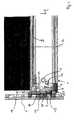
- FIG. 1shows a loading bar 1, which is arranged on a rail 2 in a loading space, vertically movable.
- the loading bar 1comprises a load receiver 4 and a shoe 5. Since the loading bar 1 is not loaded, are an edge 11 of the shoe 5 and a receiving surface 12 of the load-bearing 4 approximately at a height.
- the load bearing 4is preferably a cross-beam formed as a hollow profile, on which a load 3, see FIG. 2 , can be turned off.
- the shoe 5has an outer part 21, which engages in the rail 2, and an inner part 22.
- the inner part 22is guided in the load bearing 4 with a game. As a result, the load bearing 4 relative to the shoe 5 in the direction of arrow Y is displaced.
- the loading bar 1comprises a load pawl 7.
- the load pawl 7is in a guide 8 in the inner part 22 of the shoe 5 of the loading beam. 1 arranged.
- a load latch spring 9With a load latch spring 9, the load pawl 7 is biased relative to the shoe 5, so that the load pawl 7 is not already pressed by the weight of the load receptacle 4 in a securing opening 13 of the rail 2,
- About a load latch lever 10is the load pawl 7 with the load bearing 4 in Connection.
- the load-latch lever 10is connected via a joint 6 with the load-bearing 4 and has a further articulated connection 16 with the guide 8 of the shoe 5. From the load latch lever 10 protrudes a pressure piece 26, which can load the load pawl 7 with pressure.
- the load latch lever 10releases the load pawl 7 and this slides under the pressure of the load pawl spring 9 again from the securing opening 13. Then the loading bar 1 can be adjusted in the rail 2 quietly.
- the adjustment of the loading beam 1is manually possible in the unloaded state, but should preferably be carried out by electric motor.
- a hoist rope 14As in the FIGS. 1 and 2 shown, which is connected to a drive, not shown, provided, the hoist rope 14 is connected via a cable connection 15 with the loading bar. 1 connected, wherein the hoist rope 14 with an abutment 25, the cable connection 15 engages around.
- the loading bar 1when the load pawl 7 does not engage in a securing opening 13 in the rail 2, be adjusted via the hoist rope 14 at a height along the rail 2.
- the cable connection 15passes through the shoe 5 and is arranged on the hinge 16.
- an unillustrated stopis provided for the Sellability 15 which limits a movement of the cable holder 15 against the arrow Y upwards.
- a safety latch 17In the event of breakage of the hoist rope 14, the loading bar 1, as well as in FIG. 1 illustrated, a safety latch 17.
- the safety latch 17is biased by means of a safety pawl spring 18 against the load-bearing 4.
- a safety latch lever 19About a safety latch lever 19, the safety latch 17 is connected to the cable holder 15 and the joint 16.
- the functioning hoist cable 14holds the cable holder 15 and thus also the safety catch lever 17 against the safety latch spring 18 so that it can not press the safety catch 17 into the rail 2.
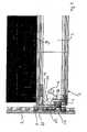
- FIG. 3shows the load bar 1 loaded with the load 3 in which the hoist rope 14 is torn.
- the hoist ropeis not shown.
- the load bearing 4is loaded with the load 3
- the load pawl 7, as to FIG. 2 describedpressed into the securing opening 13 of the rail 2 and fixes the charging bar 1, as an additional backup, the Sellability 15 is released after a hoisting rope break.
- the safety pawl lever 19rotates about the hinge 16 and allows so that the safety pawl spring 18, the safety pawl 17 presses in a further system bore 20 of the rail 2.
- the loading bar 1is additionally fixed.
- This safety mechanismis analogous to an unloaded loading bar.
Landscapes
- Engineering & Computer Science (AREA)
- Transportation (AREA)
- Mechanical Engineering (AREA)
- Load-Engaging Elements For Cranes (AREA)
- Machines For Laying And Maintaining Railways (AREA)
Description
Translated fromGermanDie Erfindung betrifft einen Ladebalken nach den Merkmalen des Oberbegriffs des Anspruchs 1.The invention relates to a loading bar according to the features of the preamble of claim 1.
Aus dem Stand der Technik sind Ladebalken für Laderäume bekannt. In einem Laderaum, bspw. einem LKW, sind an den Wänden eine Mehrzahl von Schienen vorgesehen. Diese sind meist gegenüberllegend und parallel zueinander angeordnet. Zwischen zwei gegenüberliegenden Schienen kann oder können je nach Bedarf ein oder auch eine Mehrzahl von Ladebalken eingebracht werden. Meist werden die Ladebalken mit ihren Enden in den Schienen verrastet. Nachteiligerweise ist das Verstellen der Ladebalken in den Schienen sehr laut. Dies ist vor allem für Anwohner von Ladebereichen, bspw. an Geschäften oder in Hotels, sehr unangenehm. Derartige Ladebalken sind bspw. aus der
In der
Aus der
Aus der
Aufgabe der Erfindung ist es, einen Ladebalken zum Festlegen in einer Schiene in einem Laderaum zu schaffen, der sehr geräuscharm verstellt und auf einfache Art und Weise bedient werden kann.The object of the invention is to provide a loading bar for fixing in a rail in a hold, which can be adjusted very quietly and operated in a simple manner.
Zur Lösung der Aufgabe führen die Merkmale des kennzeichnenden Teils des Anspruchs 1.To achieve the object, the features of the characterizing part of claim 1.
Ein Ladebalken zum Festlegen und Verstellen in bzw. an einer Schiene in einem Laderaum umfasst eine Lastaufnahme und einen Schuh, der in der Schiene läuft. Auf der Lastaufnahme wird das Ladegut, bspw. Paletten od. dgl., abgestellt.A loading bar for fixing and adjusting in or on a rail in a load compartment comprises a load receiver and a shoe running in the rail. On the load bearing the load, eg. Pallets od. Like., Turned off.
Bevorzugt läuft ein äusserer Teil des Schuhs in der Schiene. Ein innerer Teil des Schuhs ist mit einem Spiel in der Lastaufnahme geführt.Preferably, an outer part of the shoe runs in the rail. An inner part of the shoe is guided with a play in the load suspension.
Zweckmässigerweise umfasst der Schuh eine Lastklinke. Mittels der Lastklinke wird der Ladebalken in einer Systembohrung der Schiene festgelegt. Dazu durchgreift die Lastklinke den Schuh. Bei der Schiene handelt es sich bevorzugt um eine Airline-Schiene.Conveniently, the shoe comprises a load pawl. By means of the load pawl, the loading bar is fixed in a system bore of the rail. For this purpose, the load pawl passes through the shoe. The rail is preferably an airline rail.
Vorzugsweise ist der Schuh des Ladebalkens gegenüber der Lastaufnahme relativ bewegbar. Bevorzugt ist die Lastaufnahme in Längsrichtung der Schiene bewegbar. Dadurch ergibt sich der Vorteil, dass die Lastaufnahme bei einer Belastung durch ein Ladegut gegenüber dem Schuh beweglich ist.Preferably, the shoe of the loading beam relative to the load bearing is relatively movable. Preferably, the load bearing in the longitudinal direction of the rail is movable. This results in the advantage that the load bearing is movable against the shoe when loaded by a load.
Zweckmässigerweise umfasst der Ladebalken einen Lastklinkenhebel der mit der Lastaufnahme und dem Schuh so in Verbindung steht, dass er bei einer Relativbewegung zwischen dem Schuh und der Lastaufnahme die Lastklinke in die Schiene drückt. Bevorzugt wird die Lastklinke in eine Systembohrung in der Schiene gedrückt. Dadurch wird der Ladebalken an der Schiene in einer gewünschten Höhe fixiert.Conveniently, the loading bar comprises a load latch lever which is in communication with the load receiver and the shoe so that it presses the load pawl into the rail during a relative movement between the shoe and the load receiver. Preferably, the load pawl is pressed into a system bore in the rail. As a result, the loading bar is fixed to the rail at a desired height.
In typischen Ausführungsbeispielen ist die Lastklinke Über eine Lastklinkenfeder vorgespannt. Bevorzugt ist die Lastklinke in einer Führung, in die auch die Lastklinkenfeder eingebracht ist, geführt. Dadurch ergibt sich der Vorteil, dass der Ladebalken unbelastet nicht in der Schiene fixiert ist, sondern ohne weiteres leicht bewegt werden kann. Es wird verhindert, dass die Lastaufnahme durch ihr Eigengewicht nach unten fällt. Da die Lastklinke bei einem nicht belasteten Ladebalken vollständig aus der Schiene entfernt ist und nur der Schuh In der Schlene gleitet, ergibt sich des weiteren der Vorteil, dass der Ladebalken sehr geräuscharm verstellt werden kann.In typical embodiments, the load pawl is biased by a load pawl spring. Preferably, the load pawl is guided in a guide, in which the load pawl spring is introduced. This results in the advantage that the loading bar is unloaded not fixed in the rail, but can be easily moved easily. It is prevented that the load absorption by its own weight falls down. Since the load pawl is completely removed from the rail with a loading bar not loaded and only the shoe slides in the Schlene, there is also the advantage that the loading bar can be adjusted very quietly.
Vorteilhafterweise ist der Ladebalken über eine Seilaufnahme mit einem Hubseil verbunden. Bevorzugt ist das Hubseil in der Schiene angeordnet. Dadurch ergibt sich der Vorteil, dass das Hubseil vor Beschädigungen geschützt Ist. Ein weiterer Vorteil ist, dass das Hubseil eine zusätzliche Sicherung für den Ladebalken darstellt, bspw. wenn die Lastklinke, die Lastklinkenfeder oder der Lastklinkenhebel defekt sind.Advantageously, the loading bar is connected via a cable holder with a hoist rope. Preferably, the hoist rope is arranged in the rail. This results in the advantage that the hoist rope is protected from damage. Another advantage is that the hoist rope is an additional safeguard for the loading bar, for example when the load pawl, the load pawl spring or the load pawl lever are defective.
Zweckmässigerweise ist das Hubseil mit einem motorischen Antrieb verbunden, der geeignet ist, den Ladebalken entlang der Schiene zu verstellen. Dadurch ergibt sich der Vorteil, dass der Ladebalken oder auch eine Mehrzahl von Ladebalken auf einfache Art und Weise automatisch über den Antrieb verstellt werden können.Conveniently, the hoisting rope is connected to a motor drive, which is adapted to adjust the loading bar along the rail. This results in the advantage that the loading bar or a plurality of loading bars can be adjusted automatically via the drive in a simple manner.
In typischen Ausführungsbeispielen umfasst der Ladebalken eine Sicherungsklinke. Dadurch ergibt sich der Vorteil, dass bspw. bei einem Hubseilbruch oder einer defekten Lastklinke, Lastklinkenfeder oder Lastklinkenhebel, der belastete Ladebalken trotzdem in der gewünschten Höhe in der Schiene gehalten wird und nicht nach unten fällt.In typical embodiments, the loading bar comprises a securing pawl. This results in the advantage that, for example, in a Hubseilbruch or a defective load pawl, load pawl spring or load latch lever, the loaded loading bar is still held in the desired height in the rail and does not fall down.
Bevorzugt ist die Sicherungsklinke dazu geeignet, in die Schiene, insbesondere in eine Systembohrung der Schiene, einzurasten.Preferably, the securing pawl is adapted to engage in the rail, in particular in a system bore of the rail.
Zweckmässlgerweise Ist die Sicherungsklinke mit der Seilaufnahme verbunden. Dadurch ergibt sich der Vorteil, dass bei einem Seilbruch die Seilaufnahme entlastet wird und zulässt, dass die Sicherungsklinke in die Schiene eingreift und den Ladebalken gegen ein nach Unten-Fallen oder Rutschen sichert.Appropriately, the safety latch is connected to the cable holder. This results in the advantage that when a cable break the cable receptacle is relieved and allows the safety catch engages the rail and the loading bar against a down traps or slides secures.
Vorzugsweise ist die Sicherungsklinke und/oder die Seilaufnahme, Insbesondere über ein Gelenk, mit dem Lastklinkenhebel verbunden. Dadurch ergibt sich der Vorteil, dass bei einer Fehifunktion der Lastklinke auch die Sicherungsklinke betätigt wird.Preferably, the securing pawl and / or the cable receptacle, in particular via a joint, connected to the load latch lever. This results in the advantage that in a malfunction of the load pawl and the safety latch is actuated.
In typischen Ausführungsbeispielen ist die Sicherungsklinke mit einer Sicherungsklinkenfeder vorgespannt. Dadurch ergibt sich der Vorteil, dass verhindert wird, dass die Sicherungsklinke bei einem unbelasteten Ladebalken in der Schiene einrastet und diese festlegt. Dies ist wichtig, um zu gewährleisten, dass der Ladebalken geräuscharm verstellt werden kann, Erst durch eine Last auf der Lastaufnahme und wenn durch einen Hubseilbruch oder eine defekte Lastklinke die Sirherungsklinke freigegeben wird, kann die Vorspannung der Sicherungsklinkenfeder überwunden werden. Bei einem Seilbruch oder einer defekten Lastklinke wird die Sicherungsklinke in die Schiene bzw. eine Systembohrung in der Schiene gedrückt.In typical embodiments, the safety latch is biased with a safety latch spring. This results in the advantage that it is prevented that the securing pawl engages with an unloaded loading bar in the rail and determines this. This is important to ensure that the loading bar can be adjusted quietly, only by a load on the load bearing and if the Sirherungsklinke is released by a Hubseilbruch or a defective load pawl, the bias of the safety pawl spring can be overcome. In the event of a cable break or a defective load pawl, the safety catch is pressed into the rail or a system bore in the rail.
Vorteilhafterweise sind in dem Laderaum eine Mehrzahl von Schienen vorgesehen. Bevorzugt sind jeweils zwei Schienen gegenüberilegend angeordnet. Zwischen den gegenüberliegenden Schienen ist zumindest ein Ladebalken eingebracht. Zweckmässigerweise können auch eine Mehrzahl von Ladebalken zwischen zwei gegenoberliegenden Schienen eingebracht sein.Advantageously, a plurality of rails are provided in the cargo space. Preferably, two rails are gegenüberilegend each arranged. At least one loading bar is inserted between the opposite rails. Conveniently, a plurality of loading beams between two opposing rails may be introduced.
In allen parallel zueinander verlaufenden Schienen sind bevorzugt eine Mehrzahl von Endschaltern, besonders bevorzugt in vorbestimmten Höhen, angeordnet. Zweckmässigerweise sind die Antriebe für die einzelnen Schienen und Ladebalken so mit den Endschaltern verbunden, dass alle Ladebalken mittels eines Bedienvorgangs auf eine gewünschte Höhe eingestellt werden können. Dadurch ergibt sich der Vorteil, dass eine Mehrzahl der in einem Laderaum vorhandenen Ladebalken synchron verstellt werden können.In all mutually parallel rails preferably a plurality of limit switches, particularly preferably at predetermined heights, are arranged. Conveniently, the drives for the individual rails and loading bars are connected to the limit switches so that all the loading bars can be adjusted by means of an operating operation to a desired height. This results in the advantage that a plurality of loading bars present in a loading space can be adjusted synchronously.
Gesondert wird Schutz beansprucht für ein Ladungssicherungssystem mit zumindest einem Ladebalken nach einem der genannten Merkmale und einer Mehrzahl von Schienen, die in einem Laderaum angeordnet sind, wobei die Mehrzahl der Schienen einander zugeordnete Endschalter aufweisen, um vorbestimmte Beladepositionen zu markieren bzw. einstellen zu können.Separately, protection is claimed for a load securing system having at least one loading bar according to one of said features and a plurality of rails arranged in a loading space, the plurality of rails having associated limit switches for marking or setting predetermined loading positions.
Nachfolgend wird die Erfindung anhand der beiliegenden Figuren kurz beschrieben, wobei die Figuren zeigen:
Figur 1 zeigt eine schematische Darstellung eines Ausschnitts eines offenen Ladebalkens in einer Ausgangstellung ohne Last;Figur 2Figur 3
FIG. 1 shows a schematic representation of a section of an open loading beam in a starting position without load;FIG. 2 shows a schematic representation of a section of an open loaded loading beam;FIG. 3 shows a further schematic representation of a section of an open loaded loading beam in a broken hoist rope.
Der Ladebalken 1 umfasst eine Lastaufnahme 4 und einen Schuh 5. Da der Ladebalken 1 nicht belastet ist, liegen eine Kante 11 des Schuhs 5 und eine Aufnahmefläche 12 der Lastaufnahme 4 in etwa auf einer Höhe. Die Lastaufnahme 4 ist bevorzugt ein als Hohlprofil ausgebildeter Querbalken, auf dem ein Last 3, siehe
Der Schuh 5 weist einen äusseren Teil 21, der in die Schiene 2 eingreift, und einen inneren Teil 22 auf. Der innere Teil 22 ist in der Lastaufnahme 4 mit einem Spiel geführt. Dadurch ist die Lastaufnahme 4 gegenüber dem Schuh 5 in Pfeilrichtung Y verschiebbar.The shoe 5 has an outer part 21, which engages in the
Des Weiteren umfasst der Ladebalken 1 eine Lastklinke 7. Die Lastklinke 7 ist in einer Führung 8 in dem inneren Teil 22 des Schuhs 5 des Ladebalkens 1 angeordnet. Mit einer Lastklinkenfeder 9 ist die Lastklinke 7 gegenüber dem Schuh 5 vorgespannt, so dass die Lastklinke 7 nicht bereits durch das Eigengewicht der Lastaufnahme 4 in eine Sicherungsöffnung 13 der Schiene 2 gedrückt wird, Über einen Lastklinkenhebel 10 steht die Lastklinke 7 mit der Lastaufnahme 4 in Verbindung. Der Lastklinkenhebel 10 Ist über ein Gelenk 6 mit der Lastaufnahme 4 verbunden und weist eine weitere gelenkige Verbindung 16 mit der Führung 8 des Schuhs 5 auf. Vom Lastklinkenhebel 10 ragt ein Druckstück 26 ab, welches die Lastklinke 7 mit Druck beaufschlagen kann.Furthermore, the loading bar 1 comprises a load pawl 7. The load pawl 7 is in a guide 8 in the
Die Funktionsweise der Erfindung ist folgende:
- Wird die Lastaufnahme 4 des Ladebalkens 1 mit der Last 3 belastet, wird die Lastaufnahme 4 gegenüber dem Schuh 5 in Pfeilrichtung Y nach unten verschoben, bis eine Oberkante 23 des inneren Teils 22 des Schuhs 5 an einer Innenseite 24 der Lastaufnahme 4 anliegt, wie in
Figur 2um das Gelenk 6 gedreht und drückt so auf die Lastklinke 7, dass diese indie Sicherungsöffnung 13 inder Schiene 2 einfährt. Dadurch wird der Ladebalken 1 ander Schiene 2 fixiert. Dieser Vorgang findet auch an dem nicht dargestellten anderen Ende des Ladebalkens 1 statt.
- If the load bearing 4 of the loading beam 1 loaded with the
load 3, the load bearing 4 is shifted relative to the shoe 5 in the direction of arrow Y down until an upper edge 23 of theinner part 22 of the shoe 5 abuts an inner side 24 of the load bearing 4, as inFIG. 2 shown. In this case, the load latch lever 10 is rotated about thehinge 6 and presses on the load pawl 7 so that it enters the securingopening 13 in therail 2. As a result, the loading bar 1 is fixed to therail 2. This process also takes place at the other end of the loading beam 1, not shown.
Wird die Lastaufnahme 4 des Ladebalkens 1 wieder entlastet, so gibt der Lastklinkenhebel 10 die Lastklinke 7 frei und diese gleitet unter dem Druck der Lastklinkenfeder 9 wieder aus der Sicherungsöffnung 13. Dann kann der Ladebalken 1 geräuscharm in der Schiene 2 verstellt werden.If the load bearing 4 of the loading beam 1 is relieved again, the load latch lever 10 releases the load pawl 7 and this slides under the pressure of the load pawl spring 9 again from the securing
Das Verstellen des Ladebalkens 1 ist manuell im unbelasteten Zustand möglich, soll aber bevorzugt elektromotorisch erfolgen.The adjustment of the loading beam 1 is manually possible in the unloaded state, but should preferably be carried out by electric motor.
Zum Verstellen des Ladebalkens 1 ist ein Hubseil 14, wie in den
Im unbelasteten Zustand kann der Ladebalken 1, wenn die Lastklinke 7 nicht in eine Sicherungsöffnung 13 in der Schiene 2 eingreift, über das Hubseil 14 in einer Höhe entlang der Schiene 2 verstellt werden.In the unloaded state, the loading bar 1, when the load pawl 7 does not engage in a securing
Die Seilverbindung 15 durchgreift den Schuh 5 und ist an dem Gelenk 16 angeordnet. Zusätzlich ist für die Sellaufnahme 15 ein nicht dargestellter Anschlag vorgesehen, der eine Bewegung der Seilaufnahme 15 entgegen der Pfeilrichtung Y nach oben begrenzt.The
Als Sicherungssystem, bspw. für den Fall eines Bruchs des Hubseils 14, weist der Ladebalken 1, wie auch in
Claims (12)
- A load bar (1) for moving and securing in or on a rail (2) in a cargo space,
having a load receiver (4) for receiving a load (3),
a shoe (5) which runs in the rail (2) and
a load catch (7),
wherein the shoe (5) and the load receiver (4) are movable relative to one another,
characterized in that the shoe (5) is displaceable with respect to the load receiver (4), and
a load catch lever (10) which upon relative motion between the shoe (5) and the load receiver (4), movable in the longitudinal direction of the rail (2), fixes the load catch (7) in or on the rail (2) upon loading by the load (3). - A load bar according to claim 1,characterized in that the load catch (7) is pre-tensioned via a load catch spring (9).
- A load bar according to claim 1 or 2,characterized in that the load catch lever (10) enters into an articulated connection (6) with the load receiver (4).
- A load bar according to any one of claims 1 to 3,characterized in that the load catch lever (10) enters into an articulated connection (16) with the shoe (5).
- A load bar according to claim 4,characterized in that a pressure piece (26) is provided at the load catch lever (10) so as to be between the two articulations (6, 16) and acts upon the load catch (7) with pressure.
- A load bar according to any one of the preceding claims,characterized in that the load bar (1) is connected to a lifting cable (14) via a cable receiver (15).
- A load bar according to claim 6,characterized in that the lifting cable (14) is connected to a drive suitable for displacing the load bar (1) along the rail (2).
- A load bar according to any one of the preceding claims,characterized in that the load bar (1) comprises a safety catch (17).
- A load bar according to claim 8,characterized in that the safety catch (17) is connected to the cable receiver (15).
- A load bar according to claim 8 or 9,characterized in that the safety catch (17) and/or the cable receiver (15) is/are connected via the articulation (16) to the load catch lever (10) and/or a safety catch lever (19).
- A load bar according to any one of the preceding claims,characterized in that the safety catch (17) is pre-tensioned by a safety catch spring (18).
- A load securing system having at least one load bar (1) according to any one of the preceding claims and a plurality of rails (2),characterized in that the plurality of rails (2) have limit switches associated with one another, in order to mark predetermined loading positions.
Priority Applications (1)
| Application Number | Priority Date | Filing Date | Title |
|---|---|---|---|
| PL11007646TPL2433835T3 (en) | 2010-09-23 | 2011-09-20 | Loading bar for setting and adjusting in or on a rail in a cargo space |
Applications Claiming Priority (1)
| Application Number | Priority Date | Filing Date | Title |
|---|---|---|---|
| DE102010037753ADE102010037753A1 (en) | 2010-09-23 | 2010-09-23 | Loading bar for fixing and adjusting in or on a rail in a loading space |
Publications (2)
| Publication Number | Publication Date |
|---|---|
| EP2433835A1 EP2433835A1 (en) | 2012-03-28 |
| EP2433835B1true EP2433835B1 (en) | 2014-11-12 |
Family
ID=44650898
Family Applications (1)
| Application Number | Title | Priority Date | Filing Date |
|---|---|---|---|
| EP11007646.0ANot-in-forceEP2433835B1 (en) | 2010-09-23 | 2011-09-20 | Loading bar for setting and adjusting in or on a rail in a cargo space |
Country Status (3)
| Country | Link |
|---|---|
| EP (1) | EP2433835B1 (en) |
| DE (1) | DE102010037753A1 (en) |
| PL (1) | PL2433835T3 (en) |
Cited By (1)
| Publication number | Priority date | Publication date | Assignee | Title |
|---|---|---|---|---|
| EP3848244A1 (en) | 2020-01-09 | 2021-07-14 | WISTRA GmbH Cargo Control | Load beam |
Families Citing this family (2)
| Publication number | Priority date | Publication date | Assignee | Title |
|---|---|---|---|---|
| WO2019168846A1 (en)* | 2018-03-02 | 2019-09-06 | Ancra International Llc | Remotely adjustable captive beam system |
| DE102023115357A1 (en) | 2023-06-13 | 2024-12-19 | allsafe GmbH & Co.KG | self-propelled loading beam |
Family Cites Families (6)
| Publication number | Priority date | Publication date | Assignee | Title |
|---|---|---|---|---|
| US4553888A (en)* | 1983-06-23 | 1985-11-19 | Aeroquip Corporation | Captive dunnage fitting |
| DE9305610U1 (en)* | 1993-04-14 | 1993-07-01 | Ancra Jungfalk GmbH, 7707 Engen | Structure for the loading area of a vehicle with support tube |
| DE20115232U1 (en) | 2000-09-15 | 2001-12-13 | ANCRA Jungfalk GmbH & Co. KG, 78234 Engen | Device for securing cargo on the loading surface of a vehicle |
| US6739811B1 (en)* | 2002-12-19 | 2004-05-25 | Aero-Kit Industries Inc. | Deck beam and support rail |
| US20070224010A1 (en)* | 2006-03-24 | 2007-09-27 | Cunningham Jeffrey E | Locking device for securing loads |
| DE102008039648A1 (en)* | 2008-08-19 | 2010-03-04 | Seebauer, Kurt | Device for secure loading of e.g. lorry, with packaged goods in field of commercial freight transport, has separating element slidably moving relative to rail during movement in unlocked condition of element within rail in link-like manner |
- 2010
- 2010-09-23DEDE102010037753Apatent/DE102010037753A1/ennot_activeWithdrawn
- 2011
- 2011-09-20EPEP11007646.0Apatent/EP2433835B1/ennot_activeNot-in-force
- 2011-09-20PLPL11007646Tpatent/PL2433835T3/enunknown
Cited By (1)
| Publication number | Priority date | Publication date | Assignee | Title |
|---|---|---|---|---|
| EP3848244A1 (en) | 2020-01-09 | 2021-07-14 | WISTRA GmbH Cargo Control | Load beam |
Also Published As
| Publication number | Publication date |
|---|---|
| PL2433835T3 (en) | 2015-03-31 |
| DE102010037753A1 (en) | 2012-03-29 |
| EP2433835A1 (en) | 2012-03-28 |
Similar Documents
| Publication | Publication Date | Title |
|---|---|---|
| EP2185382B1 (en) | Apparatus for securing a container on a platform of a transport vehicle | |
| EP2627537B1 (en) | Ramp having a side barrier | |
| EP1772414A1 (en) | Foldable self-locking toe guard for elevator car | |
| EP2433835B1 (en) | Loading bar for setting and adjusting in or on a rail in a cargo space | |
| DE3876404T2 (en) | TRANSLATION NUT, APPLICABLE IN LIFTING DEVICES. | |
| DE202006013213U1 (en) | Tool cabinet moving on castors, comprises arrangement preventing unit from falling over | |
| EP1692058B1 (en) | Stacking pillar | |
| EP3153349A1 (en) | Vehicle body for a motor vehicle with a partition | |
| DE102018122634A1 (en) | Load securing system and vehicle comprising such a system and a method for securing loads | |
| AT10739U1 (en) | TRANSITION BETWEEN VEHICLE PARTS | |
| DE2423322A1 (en) | MOVING UPPER LOADING AREA FOR GOODS WAGONS | |
| EP0931532A1 (en) | Ramp for vehicles | |
| EP1726560A1 (en) | Scissor type lifting table | |
| DE3442919C2 (en) | Safety device for parking facilities | |
| AT9330U1 (en) | VEHICLE TRANSITION | |
| DE102006034666B4 (en) | Loading bridge with safety spreader and method for operating the dock leveler | |
| DE202011050603U1 (en) | Device in a funeral vehicle for loading and storing a coffin | |
| DE202008010192U1 (en) | Storage device for heavy components | |
| DE69209731T2 (en) | Freight car with sliding cover | |
| DE4207382C2 (en) | Roll-off protection on the tail lift of a vehicle | |
| AT504234B1 (en) | SLIDING DOOR OR SLIDING DOOR | |
| EP3806802A1 (en) | Transport system | |
| EP4339062B1 (en) | Method for centering or deflecting of a coupling head of a rail vehicle, and a support device for carrying out the method | |
| DE3211941A1 (en) | Box body with a liftable floor, in particular for vehicles for transporting animals | |
| AT17658U1 (en) | Vehicle for transporting people |
Legal Events
| Date | Code | Title | Description |
|---|---|---|---|
| PUAI | Public reference made under article 153(3) epc to a published international application that has entered the european phase | Free format text:ORIGINAL CODE: 0009012 | |
| AK | Designated contracting states | Kind code of ref document:A1 Designated state(s):AL AT BE BG CH CY CZ DE DK EE ES FI FR GB GR HR HU IE IS IT LI LT LU LV MC MK MT NL NO PL PT RO RS SE SI SK SM TR | |
| AX | Request for extension of the european patent | Extension state:BA ME | |
| 17P | Request for examination filed | Effective date:20120928 | |
| GRAP | Despatch of communication of intention to grant a patent | Free format text:ORIGINAL CODE: EPIDOSNIGR1 | |
| INTG | Intention to grant announced | Effective date:20140626 | |
| GRAS | Grant fee paid | Free format text:ORIGINAL CODE: EPIDOSNIGR3 | |
| GRAA | (expected) grant | Free format text:ORIGINAL CODE: 0009210 | |
| AK | Designated contracting states | Kind code of ref document:B1 Designated state(s):AL AT BE BG CH CY CZ DE DK EE ES FI FR GB GR HR HU IE IS IT LI LT LU LV MC MK MT NL NO PL PT RO RS SE SI SK SM TR | |
| REG | Reference to a national code | Ref country code:GB Ref legal event code:FG4D Free format text:NOT ENGLISH | |
| REG | Reference to a national code | Ref country code:CH Ref legal event code:EP | |
| REG | Reference to a national code | Ref country code:AT Ref legal event code:REF Ref document number:695524 Country of ref document:AT Kind code of ref document:T Effective date:20141115 | |
| REG | Reference to a national code | Ref country code:CH Ref legal event code:NV Representative=s name:ARIE WUBBEN C/O ALTAMURA GMBH, CH | |
| REG | Reference to a national code | Ref country code:IE Ref legal event code:FG4D Free format text:LANGUAGE OF EP DOCUMENT: GERMAN | |
| REG | Reference to a national code | Ref country code:DE Ref legal event code:R096 Ref document number:502011004931 Country of ref document:DE Effective date:20141224 | |
| REG | Reference to a national code | Ref country code:NL Ref legal event code:T3 | |
| REG | Reference to a national code | Ref country code:SE Ref legal event code:TRGR | |
| REG | Reference to a national code | Ref country code:PL Ref legal event code:T3 | |
| PG25 | Lapsed in a contracting state [announced via postgrant information from national office to epo] | Ref country code:PT Free format text:LAPSE BECAUSE OF FAILURE TO SUBMIT A TRANSLATION OF THE DESCRIPTION OR TO PAY THE FEE WITHIN THE PRESCRIBED TIME-LIMIT Effective date:20150312 Ref country code:FI Free format text:LAPSE BECAUSE OF FAILURE TO SUBMIT A TRANSLATION OF THE DESCRIPTION OR TO PAY THE FEE WITHIN THE PRESCRIBED TIME-LIMIT Effective date:20141112 Ref country code:NO Free format text:LAPSE BECAUSE OF FAILURE TO SUBMIT A TRANSLATION OF THE DESCRIPTION OR TO PAY THE FEE WITHIN THE PRESCRIBED TIME-LIMIT Effective date:20150212 Ref country code:LT Free format text:LAPSE BECAUSE OF FAILURE TO SUBMIT A TRANSLATION OF THE DESCRIPTION OR TO PAY THE FEE WITHIN THE PRESCRIBED TIME-LIMIT Effective date:20141112 Ref country code:ES Free format text:LAPSE BECAUSE OF FAILURE TO SUBMIT A TRANSLATION OF THE DESCRIPTION OR TO PAY THE FEE WITHIN THE PRESCRIBED TIME-LIMIT Effective date:20141112 Ref country code:IS Free format text:LAPSE BECAUSE OF FAILURE TO SUBMIT A TRANSLATION OF THE DESCRIPTION OR TO PAY THE FEE WITHIN THE PRESCRIBED TIME-LIMIT Effective date:20150312 | |
| PG25 | Lapsed in a contracting state [announced via postgrant information from national office to epo] | Ref country code:HR Free format text:LAPSE BECAUSE OF FAILURE TO SUBMIT A TRANSLATION OF THE DESCRIPTION OR TO PAY THE FEE WITHIN THE PRESCRIBED TIME-LIMIT Effective date:20141112 Ref country code:LV Free format text:LAPSE BECAUSE OF FAILURE TO SUBMIT A TRANSLATION OF THE DESCRIPTION OR TO PAY THE FEE WITHIN THE PRESCRIBED TIME-LIMIT Effective date:20141112 Ref country code:RS Free format text:LAPSE BECAUSE OF FAILURE TO SUBMIT A TRANSLATION OF THE DESCRIPTION OR TO PAY THE FEE WITHIN THE PRESCRIBED TIME-LIMIT Effective date:20141112 Ref country code:GR Free format text:LAPSE BECAUSE OF FAILURE TO SUBMIT A TRANSLATION OF THE DESCRIPTION OR TO PAY THE FEE WITHIN THE PRESCRIBED TIME-LIMIT Effective date:20150213 Ref country code:CY Free format text:LAPSE BECAUSE OF FAILURE TO SUBMIT A TRANSLATION OF THE DESCRIPTION OR TO PAY THE FEE WITHIN THE PRESCRIBED TIME-LIMIT Effective date:20141112 | |
| REG | Reference to a national code | Ref country code:DE Ref legal event code:R082 Ref document number:502011004931 Country of ref document:DE Representative=s name:PATENTANWAELTE UND RECHTSANWALT DR. WEISS, ARA, DE Ref country code:DE Ref legal event code:R082 Ref document number:502011004931 Country of ref document:DE Representative=s name:PATENTANWAELTE UND RECHTSANWALT WEISS, ARAT & , DE | |
| PG25 | Lapsed in a contracting state [announced via postgrant information from national office to epo] | Ref country code:SK Free format text:LAPSE BECAUSE OF FAILURE TO SUBMIT A TRANSLATION OF THE DESCRIPTION OR TO PAY THE FEE WITHIN THE PRESCRIBED TIME-LIMIT Effective date:20141112 Ref country code:EE Free format text:LAPSE BECAUSE OF FAILURE TO SUBMIT A TRANSLATION OF THE DESCRIPTION OR TO PAY THE FEE WITHIN THE PRESCRIBED TIME-LIMIT Effective date:20141112 Ref country code:DK Free format text:LAPSE BECAUSE OF FAILURE TO SUBMIT A TRANSLATION OF THE DESCRIPTION OR TO PAY THE FEE WITHIN THE PRESCRIBED TIME-LIMIT Effective date:20141112 Ref country code:RO Free format text:LAPSE BECAUSE OF FAILURE TO SUBMIT A TRANSLATION OF THE DESCRIPTION OR TO PAY THE FEE WITHIN THE PRESCRIBED TIME-LIMIT Effective date:20141112 Ref country code:CZ Free format text:LAPSE BECAUSE OF FAILURE TO SUBMIT A TRANSLATION OF THE DESCRIPTION OR TO PAY THE FEE WITHIN THE PRESCRIBED TIME-LIMIT Effective date:20141112 | |
| REG | Reference to a national code | Ref country code:DE Ref legal event code:R097 Ref document number:502011004931 Country of ref document:DE | |
| PLBE | No opposition filed within time limit | Free format text:ORIGINAL CODE: 0009261 | |
| STAA | Information on the status of an ep patent application or granted ep patent | Free format text:STATUS: NO OPPOSITION FILED WITHIN TIME LIMIT | |
| 26N | No opposition filed | Effective date:20150813 | |
| PG25 | Lapsed in a contracting state [announced via postgrant information from national office to epo] | Ref country code:SI Free format text:LAPSE BECAUSE OF FAILURE TO SUBMIT A TRANSLATION OF THE DESCRIPTION OR TO PAY THE FEE WITHIN THE PRESCRIBED TIME-LIMIT Effective date:20141112 | |
| PG25 | Lapsed in a contracting state [announced via postgrant information from national office to epo] | Ref country code:MC Free format text:LAPSE BECAUSE OF FAILURE TO SUBMIT A TRANSLATION OF THE DESCRIPTION OR TO PAY THE FEE WITHIN THE PRESCRIBED TIME-LIMIT Effective date:20141112 | |
| REG | Reference to a national code | Ref country code:IE Ref legal event code:MM4A | |
| PG25 | Lapsed in a contracting state [announced via postgrant information from national office to epo] | Ref country code:IE Free format text:LAPSE BECAUSE OF NON-PAYMENT OF DUE FEES Effective date:20150920 | |
| REG | Reference to a national code | Ref country code:FR Ref legal event code:PLFP Year of fee payment:6 | |
| PGFP | Annual fee paid to national office [announced via postgrant information from national office to epo] | Ref country code:IT Payment date:20160929 Year of fee payment:6 | |
| PG25 | Lapsed in a contracting state [announced via postgrant information from national office to epo] | Ref country code:MT Free format text:LAPSE BECAUSE OF FAILURE TO SUBMIT A TRANSLATION OF THE DESCRIPTION OR TO PAY THE FEE WITHIN THE PRESCRIBED TIME-LIMIT Effective date:20141112 | |
| PG25 | Lapsed in a contracting state [announced via postgrant information from national office to epo] | Ref country code:BG Free format text:LAPSE BECAUSE OF FAILURE TO SUBMIT A TRANSLATION OF THE DESCRIPTION OR TO PAY THE FEE WITHIN THE PRESCRIBED TIME-LIMIT Effective date:20141112 Ref country code:SM Free format text:LAPSE BECAUSE OF FAILURE TO SUBMIT A TRANSLATION OF THE DESCRIPTION OR TO PAY THE FEE WITHIN THE PRESCRIBED TIME-LIMIT Effective date:20141112 Ref country code:HU Free format text:LAPSE BECAUSE OF FAILURE TO SUBMIT A TRANSLATION OF THE DESCRIPTION OR TO PAY THE FEE WITHIN THE PRESCRIBED TIME-LIMIT; INVALID AB INITIO Effective date:20110920 | |
| PG25 | Lapsed in a contracting state [announced via postgrant information from national office to epo] | Ref country code:BE Free format text:LAPSE BECAUSE OF NON-PAYMENT OF DUE FEES Effective date:20150930 | |
| REG | Reference to a national code | Ref country code:FR Ref legal event code:PLFP Year of fee payment:7 | |
| REG | Reference to a national code | Ref country code:DE Ref legal event code:R082 Ref document number:502011004931 Country of ref document:DE Representative=s name:PATENTANWAELTE UND RECHTSANWALT WEISS, ARAT & , DE Ref country code:DE Ref legal event code:R081 Ref document number:502011004931 Country of ref document:DE Owner name:ALLSAFE GMBH & CO.KG, DE Free format text:FORMER OWNER: ALLSAFE JUNGFALK GMBH & CO. KG, 78234 ENGEN, DE | |
| PGFP | Annual fee paid to national office [announced via postgrant information from national office to epo] | Ref country code:TR Payment date:20170920 Year of fee payment:7 | |
| PG25 | Lapsed in a contracting state [announced via postgrant information from national office to epo] | Ref country code:MK Free format text:LAPSE BECAUSE OF FAILURE TO SUBMIT A TRANSLATION OF THE DESCRIPTION OR TO PAY THE FEE WITHIN THE PRESCRIBED TIME-LIMIT Effective date:20141112 | |
| PG25 | Lapsed in a contracting state [announced via postgrant information from national office to epo] | Ref country code:IT Free format text:LAPSE BECAUSE OF NON-PAYMENT OF DUE FEES Effective date:20170920 | |
| REG | Reference to a national code | Ref country code:FR Ref legal event code:PLFP Year of fee payment:8 | |
| PG25 | Lapsed in a contracting state [announced via postgrant information from national office to epo] | Ref country code:AL Free format text:LAPSE BECAUSE OF FAILURE TO SUBMIT A TRANSLATION OF THE DESCRIPTION OR TO PAY THE FEE WITHIN THE PRESCRIBED TIME-LIMIT Effective date:20141112 | |
| PGFP | Annual fee paid to national office [announced via postgrant information from national office to epo] | Ref country code:LU Payment date:20200921 Year of fee payment:10 Ref country code:NL Payment date:20200921 Year of fee payment:10 Ref country code:FR Payment date:20200921 Year of fee payment:10 | |
| PGFP | Annual fee paid to national office [announced via postgrant information from national office to epo] | Ref country code:SE Payment date:20200923 Year of fee payment:10 Ref country code:AT Payment date:20200918 Year of fee payment:10 Ref country code:CH Payment date:20200925 Year of fee payment:10 | |
| PGFP | Annual fee paid to national office [announced via postgrant information from national office to epo] | Ref country code:PL Payment date:20201008 Year of fee payment:10 | |
| REG | Reference to a national code | Ref country code:SE Ref legal event code:EUG | |
| REG | Reference to a national code | Ref country code:NL Ref legal event code:MM Effective date:20211001 | |
| REG | Reference to a national code | Ref country code:CH Ref legal event code:PL | |
| REG | Reference to a national code | Ref country code:AT Ref legal event code:MM01 Ref document number:695524 Country of ref document:AT Kind code of ref document:T Effective date:20210920 | |
| PG25 | Lapsed in a contracting state [announced via postgrant information from national office to epo] | Ref country code:TR Free format text:LAPSE BECAUSE OF NON-PAYMENT OF DUE FEES Effective date:20180920 Ref country code:NL Free format text:LAPSE BECAUSE OF NON-PAYMENT OF DUE FEES Effective date:20211001 | |
| PG25 | Lapsed in a contracting state [announced via postgrant information from national office to epo] | Ref country code:SE Free format text:LAPSE BECAUSE OF NON-PAYMENT OF DUE FEES Effective date:20210921 Ref country code:LU Free format text:LAPSE BECAUSE OF NON-PAYMENT OF DUE FEES Effective date:20210920 Ref country code:FR Free format text:LAPSE BECAUSE OF NON-PAYMENT OF DUE FEES Effective date:20210930 | |
| PG25 | Lapsed in a contracting state [announced via postgrant information from national office to epo] | Ref country code:LI Free format text:LAPSE BECAUSE OF NON-PAYMENT OF DUE FEES Effective date:20210930 Ref country code:CH Free format text:LAPSE BECAUSE OF NON-PAYMENT OF DUE FEES Effective date:20210930 Ref country code:AT Free format text:LAPSE BECAUSE OF NON-PAYMENT OF DUE FEES Effective date:20210920 | |
| PGFP | Annual fee paid to national office [announced via postgrant information from national office to epo] | Ref country code:GB Payment date:20220927 Year of fee payment:12 | |
| PGFP | Annual fee paid to national office [announced via postgrant information from national office to epo] | Ref country code:DE Payment date:20221125 Year of fee payment:12 | |
| PG25 | Lapsed in a contracting state [announced via postgrant information from national office to epo] | Ref country code:PL Free format text:LAPSE BECAUSE OF NON-PAYMENT OF DUE FEES Effective date:20210920 | |
| P01 | Opt-out of the competence of the unified patent court (upc) registered | Effective date:20230530 | |
| REG | Reference to a national code | Ref country code:DE Ref legal event code:R119 Ref document number:502011004931 Country of ref document:DE | |
| GBPC | Gb: european patent ceased through non-payment of renewal fee | Effective date:20230920 | |
| PG25 | Lapsed in a contracting state [announced via postgrant information from national office to epo] | Ref country code:GB Free format text:LAPSE BECAUSE OF NON-PAYMENT OF DUE FEES Effective date:20230920 | |
| PG25 | Lapsed in a contracting state [announced via postgrant information from national office to epo] | Ref country code:GB Free format text:LAPSE BECAUSE OF NON-PAYMENT OF DUE FEES Effective date:20230920 Ref country code:DE Free format text:LAPSE BECAUSE OF NON-PAYMENT OF DUE FEES Effective date:20240403 |