EP2433553A1 - Video stylet with directable tip - Google Patents
Video stylet with directable tipDownload PDFInfo
- Publication number
- EP2433553A1 EP2433553A1EP11182551AEP11182551AEP2433553A1EP 2433553 A1EP2433553 A1EP 2433553A1EP 11182551 AEP11182551 AEP 11182551AEP 11182551 AEP11182551 AEP 11182551AEP 2433553 A1EP2433553 A1EP 2433553A1
- Authority
- EP
- European Patent Office
- Prior art keywords
- video
- stylet
- image data
- laryngoscope
- intubation system
- Prior art date
- Legal status (The legal status is an assumption and is not a legal conclusion. Google has not performed a legal analysis and makes no representation as to the accuracy of the status listed.)
- Withdrawn
Links
- 238000002627tracheal intubationMethods0.000claimsabstractdescription36
- 238000005286illuminationMethods0.000claimsdescription11
- 230000003213activating effectEffects0.000claims1
- 210000003437tracheaAnatomy0.000abstractdescription11
- 238000000034methodMethods0.000description15
- 230000008569processEffects0.000description13
- 210000003484anatomyAnatomy0.000description11
- 238000003384imaging methodMethods0.000description9
- 210000001260vocal cordAnatomy0.000description6
- 239000000835fiberSubstances0.000description5
- 238000012423maintenanceMethods0.000description5
- 230000008901benefitEffects0.000description4
- 230000006870functionEffects0.000description4
- 230000003287optical effectEffects0.000description4
- 229910052782aluminiumInorganic materials0.000description3
- XAGFODPZIPBFFR-UHFFFAOYSA-NaluminiumChemical compound[Al]XAGFODPZIPBFFR-UHFFFAOYSA-N0.000description3
- 230000005540biological transmissionEffects0.000description3
- 210000000867larynxAnatomy0.000description3
- 229920003023plasticPolymers0.000description3
- 238000012545processingMethods0.000description3
- 230000029058respiratory gaseous exchangeEffects0.000description3
- 230000009471actionEffects0.000description2
- 238000004891communicationMethods0.000description2
- 230000008878couplingEffects0.000description2
- 238000010168coupling processMethods0.000description2
- 238000005859coupling reactionMethods0.000description2
- 238000010586diagramMethods0.000description2
- 210000002409epiglottisAnatomy0.000description2
- 238000003780insertionMethods0.000description2
- 230000037431insertionEffects0.000description2
- 239000000463materialSubstances0.000description2
- 238000012986modificationMethods0.000description2
- 230000004048modificationEffects0.000description2
- 206010002091AnaesthesiaDiseases0.000description1
- RYGMFSIKBFXOCR-UHFFFAOYSA-NCopperChemical compound[Cu]RYGMFSIKBFXOCR-UHFFFAOYSA-N0.000description1
- 239000000956alloySubstances0.000description1
- 229910045601alloyInorganic materials0.000description1
- 230000003321amplificationEffects0.000description1
- 230000037005anaesthesiaEffects0.000description1
- QVGXLLKOCUKJST-UHFFFAOYSA-Natomic oxygenChemical compound[O]QVGXLLKOCUKJST-UHFFFAOYSA-N0.000description1
- 238000006243chemical reactionMethods0.000description1
- 230000001427coherent effectEffects0.000description1
- 230000000295complement effectEffects0.000description1
- 229910052802copperInorganic materials0.000description1
- 239000010949copperSubstances0.000description1
- 230000034994deathEffects0.000description1
- 231100000517deathToxicity0.000description1
- 210000003811fingerAnatomy0.000description1
- 239000013305flexible fiberSubstances0.000description1
- 229920002457flexible plasticPolymers0.000description1
- 238000005259measurementMethods0.000description1
- 229910044991metal oxideInorganic materials0.000description1
- 150000004706metal oxidesChemical class0.000description1
- 238000003199nucleic acid amplification methodMethods0.000description1
- 239000013307optical fiberSubstances0.000description1
- 229910052760oxygenInorganic materials0.000description1
- 239000001301oxygenSubstances0.000description1
- 230000002035prolonged effectEffects0.000description1
- 230000001681protective effectEffects0.000description1
- 238000012552reviewMethods0.000description1
- 239000004065semiconductorSubstances0.000description1
- 238000001356surgical procedureMethods0.000description1
- 230000001360synchronised effectEffects0.000description1
- 210000003813thumbAnatomy0.000description1
- 238000009423ventilationMethods0.000description1
Images


Classifications
- A—HUMAN NECESSITIES
- A61—MEDICAL OR VETERINARY SCIENCE; HYGIENE
- A61B—DIAGNOSIS; SURGERY; IDENTIFICATION
- A61B1/00—Instruments for performing medical examinations of the interior of cavities or tubes of the body by visual or photographical inspection, e.g. endoscopes; Illuminating arrangements therefor
- A61B1/267—Instruments for performing medical examinations of the interior of cavities or tubes of the body by visual or photographical inspection, e.g. endoscopes; Illuminating arrangements therefor for the respiratory tract, e.g. laryngoscopes, bronchoscopes
- A—HUMAN NECESSITIES
- A61—MEDICAL OR VETERINARY SCIENCE; HYGIENE
- A61B—DIAGNOSIS; SURGERY; IDENTIFICATION
- A61B1/00—Instruments for performing medical examinations of the interior of cavities or tubes of the body by visual or photographical inspection, e.g. endoscopes; Illuminating arrangements therefor
- A61B1/00002—Operational features of endoscopes
- A61B1/00043—Operational features of endoscopes provided with output arrangements
- A61B1/00045—Display arrangement
- A61B1/0005—Display arrangement combining images e.g. side-by-side, superimposed or tiled
- A—HUMAN NECESSITIES
- A61—MEDICAL OR VETERINARY SCIENCE; HYGIENE
- A61B—DIAGNOSIS; SURGERY; IDENTIFICATION
- A61B1/00—Instruments for performing medical examinations of the interior of cavities or tubes of the body by visual or photographical inspection, e.g. endoscopes; Illuminating arrangements therefor
- A61B1/00002—Operational features of endoscopes
- A61B1/00043—Operational features of endoscopes provided with output arrangements
- A61B1/00045—Display arrangement
- A61B1/00052—Display arrangement positioned at proximal end of the endoscope body
- A—HUMAN NECESSITIES
- A61—MEDICAL OR VETERINARY SCIENCE; HYGIENE
- A61B—DIAGNOSIS; SURGERY; IDENTIFICATION
- A61B1/00—Instruments for performing medical examinations of the interior of cavities or tubes of the body by visual or photographical inspection, e.g. endoscopes; Illuminating arrangements therefor
- A61B1/005—Flexible endoscopes
- A61B1/0051—Flexible endoscopes with controlled bending of insertion part
- A—HUMAN NECESSITIES
- A61—MEDICAL OR VETERINARY SCIENCE; HYGIENE
- A61B—DIAGNOSIS; SURGERY; IDENTIFICATION
- A61B1/00—Instruments for performing medical examinations of the interior of cavities or tubes of the body by visual or photographical inspection, e.g. endoscopes; Illuminating arrangements therefor
- A61B1/04—Instruments for performing medical examinations of the interior of cavities or tubes of the body by visual or photographical inspection, e.g. endoscopes; Illuminating arrangements therefor combined with photographic or television appliances
- A61B1/042—Instruments for performing medical examinations of the interior of cavities or tubes of the body by visual or photographical inspection, e.g. endoscopes; Illuminating arrangements therefor combined with photographic or television appliances characterised by a proximal camera, e.g. a CCD camera
- A—HUMAN NECESSITIES
- A61—MEDICAL OR VETERINARY SCIENCE; HYGIENE
- A61B—DIAGNOSIS; SURGERY; IDENTIFICATION
- A61B1/00—Instruments for performing medical examinations of the interior of cavities or tubes of the body by visual or photographical inspection, e.g. endoscopes; Illuminating arrangements therefor
- A61B1/06—Instruments for performing medical examinations of the interior of cavities or tubes of the body by visual or photographical inspection, e.g. endoscopes; Illuminating arrangements therefor with illuminating arrangements
- A—HUMAN NECESSITIES
- A61—MEDICAL OR VETERINARY SCIENCE; HYGIENE
- A61M—DEVICES FOR INTRODUCING MEDIA INTO, OR ONTO, THE BODY; DEVICES FOR TRANSDUCING BODY MEDIA OR FOR TAKING MEDIA FROM THE BODY; DEVICES FOR PRODUCING OR ENDING SLEEP OR STUPOR
- A61M16/00—Devices for influencing the respiratory system of patients by gas treatment, e.g. ventilators; Tracheal tubes
- A61M16/04—Tracheal tubes
- A61M16/0488—Mouthpieces; Means for guiding, securing or introducing the tubes
- A—HUMAN NECESSITIES
- A61—MEDICAL OR VETERINARY SCIENCE; HYGIENE
- A61B—DIAGNOSIS; SURGERY; IDENTIFICATION
- A61B1/00—Instruments for performing medical examinations of the interior of cavities or tubes of the body by visual or photographical inspection, e.g. endoscopes; Illuminating arrangements therefor
- A61B1/00064—Constructional details of the endoscope body
- A61B1/00071—Insertion part of the endoscope body
- A61B1/0008—Insertion part of the endoscope body characterised by distal tip features
- A61B1/00082—Balloons
- A—HUMAN NECESSITIES
- A61—MEDICAL OR VETERINARY SCIENCE; HYGIENE
- A61B—DIAGNOSIS; SURGERY; IDENTIFICATION
- A61B1/00—Instruments for performing medical examinations of the interior of cavities or tubes of the body by visual or photographical inspection, e.g. endoscopes; Illuminating arrangements therefor
- A61B1/04—Instruments for performing medical examinations of the interior of cavities or tubes of the body by visual or photographical inspection, e.g. endoscopes; Illuminating arrangements therefor combined with photographic or television appliances
- A61B1/044—Instruments for performing medical examinations of the interior of cavities or tubes of the body by visual or photographical inspection, e.g. endoscopes; Illuminating arrangements therefor combined with photographic or television appliances for absorption imaging
- A—HUMAN NECESSITIES
- A61—MEDICAL OR VETERINARY SCIENCE; HYGIENE
- A61B—DIAGNOSIS; SURGERY; IDENTIFICATION
- A61B1/00—Instruments for performing medical examinations of the interior of cavities or tubes of the body by visual or photographical inspection, e.g. endoscopes; Illuminating arrangements therefor
- A61B1/267—Instruments for performing medical examinations of the interior of cavities or tubes of the body by visual or photographical inspection, e.g. endoscopes; Illuminating arrangements therefor for the respiratory tract, e.g. laryngoscopes, bronchoscopes
- A61B1/2676—Bronchoscopes
- A—HUMAN NECESSITIES
- A61—MEDICAL OR VETERINARY SCIENCE; HYGIENE
- A61M—DEVICES FOR INTRODUCING MEDIA INTO, OR ONTO, THE BODY; DEVICES FOR TRANSDUCING BODY MEDIA OR FOR TAKING MEDIA FROM THE BODY; DEVICES FOR PRODUCING OR ENDING SLEEP OR STUPOR
- A61M2205/00—General characteristics of the apparatus
- A61M2205/58—Means for facilitating use, e.g. by people with impaired vision
- A61M2205/587—Lighting arrangements
Definitions
- the inventionrelates to a video stylet with a tip that may be directed by a user, and more specifically, to a combination video stylet and the video laryngoscope combination where both the video stylet and laryngoscope are provided with a similar image sensor providing a split screen view for the user.
- Some of the difficulties the user encountersinclude: the restriction of view as the tube is inserted, variations in the anatomy of the patients, an uncomfortable and unnatural position for the anesthesiologist while holding the instrument and the necessity for rapid intubation.
- Video laryngoscopeshave been used to help facilitate the intubation of a patient.
- Video laryngoscopestypically contain a light guiding system, usually in the form of fiber optic cables, in order to bring light to the surgical area.
- Video laryngoscopesalso typically contain an image guiding system, for example in the form of a rigid rod lens system, arranged in the blade of the laryngoscope, or in the form of an ordered, flexible fiber optic bundle. In these configurations, the image guiding system is utilized to transmit reflected light from the area ahead of the blade to a camera, which may be attached to the laryngoscope.
- an imagerwhich may comprise, for example, a Charge Couple Device (CCD), or Complementary Metal Oxide Semiconductor (CMOS) to the distal end of the laryngoscope blade.
- CCDCharge Couple Device
- CMOSComplementary Metal Oxide Semiconductor
- the image datamay be transmitted to the camera affixed to the laryngoscope via electrical wires (or wirelessly) as digital image data.
- the imaging devicetypically positioned on the underside and distal end of the laryngoscope blade, only provides a view of the, roughly, two-thirds of the configuration of the anatomy (depending on the patient it could be more or less) with the lower one-third not visible to the user.
- ETTEndotracheal Tube
- a malleable aluminum styletis an accessory used with the ETT (typically inserted into the tube) to provide the tube with additional rigidity for the intubation process.
- the anatomy of patientsoften requires that the tip of the ETT to have a sharper bend and be partially more rigid so as to introduce it through the vocal cords, which are located toward an anterior (at the 12 o'clock) position.
- the styletwhich may comprise a malleable aluminum rod covered with a plastic material (disposable) is slid inside the ETT and is used to increase the bend of the tip of the ETT and form the proper angulation for the particular patient. After intubation, the stylet is removed and the ETT remains in place.
- a video laryngoscope systemthat provides a split image simultaneously to a user, such that, the user is provided with a greater field of view.
- the video laryngoscope systemincludes a video laryngoscope having an imaging device positioned at a distal end of the blade and a flexible stylet having an imaging device positioned at a distal end of the stylet.
- the two imaging devicesprovide two different views of the patient's anatomy during the intubation process. These two image streams may then be presented to the user on a display(s) (e.g., two different monitors positioned side-by-side or a single monitor provided with a split screen).
- a display(s)e.g., two different monitors positioned side-by-side or a single monitor provided with a split screen.
- the video styletmay be provided as a flexible member that allows the user to actuate the tip allowing the tip to deflect to the proper angulation or bend radius for the patient's particular anatomy. This provides the further benefit that the video stylet does not need to be removed from the trachea in order for the user to alter the angulation of the tip, thereby reducing the time needed to complete the intubation process.
- the tipis deflectable by mechanical actuation where the user need only pull a lever of the grip handle to deflect the tip.
- the video styletis provided having a pistol-type grip with a trigger-type lever, thereby facilitating easy gripping and manipulation by the user. It is contemplated that the tip will be deflectable in one plane, however, it is understood that the tip may further be deflectable in multiple planes with the addition of further controls.
- the video styletmay also be provided with a camera that is detachably connected to a proximal end of the video stylet.
- the cameramay be provided with image processing circuitry and may receive image data from the imaging device on the distal end of the video stylet.
- the video styletis provided with fiber optical cables running along a longitudinal length of the video stylet such that light from the area ahead of the distal end of the video stylet is picked up and transmitted to the camera, which in turn, processed the received light into image data.
- a light sourcefor example, an Light Emitting Diode (LED) is positioned at the distal end of the video stylet (either in the detachable camera or in the video stylet it self), for generating illuminating light. The illuminating light is transmitted through the video stylet via illumination cable (fiber optic cables) to an area ahead of the distal end of the video stylet.
- LEDLight Emitting Diode
- the video styletmay further be provided as either a wired or wireless device.
- the devicemay include a power cable for providing electrical power to the electronics and illuminating device, or electrical power may be provided via battery power (such as a rechargeable battery).
- the video styletmay be wirelessly powered via resonant coupling as disclosed in previous U.S. Patent Application Publication No. 2010/0179384 A1 .
- the image data generated by the imaging devicemay be coupled to a control unit or a directly to a display via a cable (e.g., a digital cable connection) or may be wirelessly transmitted to the control unit or directly to the display.
- control unitmay comprise a configurable control unit, such that, upon connection of the video stylet with the control unit, the control unit automatically identifies the particular video stylet and/or associated camera and configures itself to properly function with the video stylet to, for example, process image data from, and receive/send control and/or command signals with the particular video stylet.
- the video stylet and/or the detachable cameramay comprise storage having video stylet and/or camera information identifying the type of video stylet and/or camera.
- the storagemay comprise video stylet and/or camera use and maintenance data, which may be updated as the video stylet and/or camera are used. Additionally, all of the image data, control/command, maintenance and/or use data may be transmitted and stored over a network connection.
- the video laryngoscopemay be provided with similar functionality as discussed in connection with the video stylet except that the laryngoscope imaging device is positioned typically at a distal end of the blade coupled to the laryngoscope handle.
- the laryngoscopemay further be provided with, for example, a Macintosh-type of blade the may detachably connectable with the handle of the laryngoscope.
- the handle of the laryngoscopemay also be provided with a piston-type grip facilitating ease of gripping for the user.
- both the video laryngoscope and video styletworking on conjunction with each other, the user is able to obtain a full view of both the upper and lower portions (shown simultaneously on a display(s)) of the patient's anatomy during the intubation process, which provides for a safer and quicker intubation process.
- datameans any indicia, signals, marks, symbols, domains, symbol sets, representations, and any other physical form or forms representing information, whether permanent or temporary, whether visible, audible, acoustic, electric, magnetic, electromagnetic or otherwise manifested.
- dataas used to represent predetermined information in one physical form shall be deemed to encompass any and all representations of the same predetermined information in a different physical form or forms.
- networkincludes both networks and internetworks of all kinds, including the Internet, and is not limited to any particular network or inter-network.
- first and secondare used to distinguish one element, set, data, object or thing from another, and are not used to designate relative position or arrangement in time.
- Coupledmeans a relationship between or among two or more devices, apparatus, files, programs, media, components, networks, systems, subsystems, and/or means, constituting any one or more of (a) a connection, whether direct or through one or more other devices, apparatus, files, programs, media, components, networks, systems, subsystems, or means, (b) a communications relationship, whether direct or through one or more other devices, apparatus, files, programs, media, components, networks, systems, subsystems, or means, and/or (c) a functional relationship in which the operation of any one or more devices, apparatus, files, programs, media, components, networks, systems, subsystems, or means depends, in whole or in part, on the operation of any one or more others thereof.
- processand “processing” as used herein each mean an action or a series of actions including, for example, but not limited to: the continuous or non-continuous, synchronous or asynchronous; direction of data; modification of data; formatting and/or conversion of data; tagging or annotation of data; measurement, comparison and/or review of data; and may or may not comprise a program.
- a video intubation systemincluding a video stylet for inserting into an ETT and a video laryngoscope having a laryngoscope imager generating image data
- the video styletcomprises a housing having a distal and a proximal end, the housing comprising a pistol-type grip and an control interface.
- the video styletalso includes a shaft including a distal and a proximal end, the proximal end of the shaft coupled to the distal end of the housing and the distal end of the shaft comprising a deflectable section, where deflection of the deflectable section is controlled by the control interface.
- the video styletfurther includes an illumination source generating illuminating light for illuminating an area ahead of the distal end the shaft and a video stylet imager positioned in the deflectable section of the shaft, the video stylet imager generating image data of an area ahead of the distal end the shaft.
- the video styletstill further includes a video stylet camera coupled to the housing, the video stylet camera receiving the image data, and a display coupled to the camera and to the laryngoscope imager, the display receiving both the image data from the video stylet imager and the laryngoscope imager.
- the video intubation systemis provided such that both the image data generated by the video stylet imager and the image data generated by the laryngoscope imager are simultaneously displayed.
- Figs. 1 and 2illustrate a stylet 10 and ETT 100, as is known in the prior art.
- Stylet 10typically comprises a malleable aluminum rod with a plastic cover.
- the ETTtypically comprises a plastic material with a distal end 102 with an inflatable cuff 104 positioned near distal end 102.
- the inflatable cuff 104can be expanded to form a seal around the ETT and the inner surface of the treacha.
- the stylet 10may be withdrawn and the ETT connected to a machine to facilitate breathing for the patient.
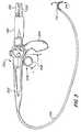
- Fig. 3is an illustration of one advantageous embodiment of the video stylet 200.
- the video stylet 200includes a housing 202 having a handle 204, which in this illustration, is provided in the form of a pistol-type grip with a control interface 206.
- the control interface 206is provided in the form of a trigger-type lever having a closed loop 208 into which a user may insert a finger.
- the video stylet 200also includes a shaft 210 coupled at one end to the housing 202.
- Shaft 210further includes a deflectable section 212 located at a distal end 214 of shaft 210. Actuation of control interface 206 allows a user to actuate deflectable section 212 as indicated by the arrows in Fig. 3 .
- Camera 218may be provided detachably coupled ( Fig. 4 ) to housing 202 such that different cameras (218, 218' ... 218 n ) may be attached to housing 202.
- camera 218is provided with multiple channels for transmitting power and information.
- illuminating lightmay be provided via an optical channel 222 (which may comprise fiber optic cables), while image data may be transmitted from camera 218 via data channel 220 (which may comprise two or more copper wires).
- data channel 220which may comprise two or more copper wires.
- optical channel 222 and data channel 220are illustrated as comprising two different cables, it is understood that both may be consolidating as a single cable surrounded by a protective jacketing (not shown).
- Illuminating lightwill then be transmitted from camera 218 through housing 202 and shaft 210 out the distal end 214 to illuminate the area ahead of the shaft. Reflected light is then picked-up and transmitted back to camera 218, which converts the received light to image data. It is contemplated that the transmitted and received light may be transmitted via coherent optical fibers.
- a video stylet imager 216is located at the distal end 214 (see Fig. 7 ).
- Video stylet imager 216is provided to convert received light into digital image data, which in turn, is transmitted to housing 202 on onward to a display ( FIGS. 6 & 8 ). It is contemplated that video stylet imager 216 may comprise virtually any type of digital imaging device, including, but not limited to, a CMOS device or a CCD.
- the video stylet 200may be used in conjunction with ETT 100.
- shaft 210may be inserted into a proximal end 106 of ETT 100.
- the distal end 102 of ETT 100may then be guided by a user controlling the movement of deflectable section 212.
- Thisprovides a distinct advantage over the prior art stylet 10. For example, when a user intubates a patient with stylet 10, the user must pre-bend the stylet 10 (typically made of a malleable alloy) to provide a particular bend radius to distal end 102.
- the userwill be required to remove the ETT/stylet (100,10), adjust the bend of the distal end 12 of stylet 10, and try to intubate the patient a second time.
- the userneed only view the image data being transmitted by the video stylet imager 216 and actuate the control interface 206 to adjust the bend radius of distal end 102 to the desired angle for the particular patient without the need to remove ETT 100. This results in a faster intubation with a lower chance of causing damage to the patient during the intubation process.
- FIGS. 6-9Fig. 6 is a block diagram of a video intubation system
- FIGS. 7-9are illustrations of various embodiments O the video stylet 200 used in conjunction with a video laryngoscope 300.
- the video intubation systemis illustrated in these embodiments comprising the video stylet 200 with (or without) detachable camera 218 coupled to housing 202.
- the camera 218is shown ( FIGS. 8 & 9 ) coupled to a control unit 226 via a cable 224 (which may comprise, for example, optical channel 222 and data channel 220; cable 224' for video laryngoscope 300).
- cable 224which may comprise, for example, optical channel 222 and data channel 220; cable 224' for video laryngoscope 300.
- cable 224which may comprise, for example, optical channel 222 and data channel 220; cable 224' for video laryngoscope 300.
- camera 218may be wirelessly coupled to control unit 226.
- the camera 218may be replaced by use of a video stylet imager 216, which may be positioned at the distal end 214 of the shaft 210.
- image datais generated by the video stylet imager 216 and transmitted to the display.
- Video stylet electronics 228is shown coupled to video stylet imager 216 via an image data channel 230. An arrow is provided to indicate that image data generated by video stylet imager 216, may in this embodiment, be transmitted to video stylet electronics 228.
- Video stylet electronics 228may or may not be utilized, and when utilized may comprise, but is not limited to, processing circuitry, amplification circuitry, memory (e.g., cache memory), etc.
- storage 232is also illustrated in housing 202 , which is provided as a memory to storage video stylet information, including but not limited to, identification data, configuration data, use data and maintenance data. Storage 232 may further be provided to store image data as needed.
- the image datamay, in certain embodiments, be transmitted from video stylet electronics 228 to camera electronics 234 (when used), which may be provided to generate image data from the received reflected light.
- the image datamay be generated by the video stylet imager 216 and received by video stylet electronics 228 for transmission to the display.
- the generated/processed image datamay be transmitted to control unit 226 via cable 224 (or wirelessly).
- the control unitmay be used to further process the information (by means of control unit electronics 236) and/or transmit the image data to display 238 via connection 240.
- cable 224 coupling camera 218 to control unit 226is illustrated with a two-way arrow, which is provided to indicate two-way communication.
- the video stylet 200transmits video stylet information, such as, for example, identification/use/maintenance data to control unit 226.
- Control unit 226may then use this information to automatically configure to function properly with video stylet 200.
- command and control datamay be transmitted to video stylet 200 from control unit 226, and image data is also transmitted from video stylet 200 to control unit 226.
- an input device 242keyboard, mouse, track pad, microphone, etc.
- display 238may be provided as a touch screen control device, which may be used to display both image data and provide for control/command inputs.
- Storage device 244is provided to store, for example, the received image data.
- Storage device 244may comprise virtually any type of digital storage device and may be internal or external to control unit 226, including a magnetic, high density hard drive, a writable medium including a CD/DVD, or card inserted into the screen casing including, for example, a removable drive, such as a thumb drive, volatile or non-volatile memory, etc. It is further contemplated that storage 244 may have saved thereon, configuration data for configuration of control unit 226 so that control unit 226 may properly process the received image data and control video stylet 200.
- Control unit 226is further shown coupled to computer 246 via a network connection 248. It is contemplated that network connection 248 may comprise, for example, an Internet connection. Computer 246 is further coupled to a remote storage 248, which may comprise virtually any type of memory device as is described in connection with storage 244. Additionally, virtually any type of digital data may be saved on remote storage 248, such as, but not limited to, configuration data, update information, image data, etc.
- illumination source 250is also shown in camera 218. It should be noted that illumination source 250 may be positioned in camera 218 (as illustrated), or in housing 202 or be positioned in control unit 226 (indicated as illumination source 250'). In the case where illumination source 250 is positioned in either camera 218 or housing 202, cable 224 would then only comprise a digital transmission cable for transmitting image data, control/command data, update, use, maintenance data, etc. However, in the embodiment where the illumination source 250' is positioned in control unit 226, cable 224 would then be provided with a fiber optic channel for transmission of illuminating light from illumination source 250' to video stylet 200. In either case, illuminating light is transmitted via illuminating light channel 252.
- video laryngoscope 300which is provided with a housing 302, a blade 304 coupled to housing 302 and a camera 306 (if necessary) coupled to housing 302.
- the blade 304may be provided with a laryngoscope imager 308, which may comprise, for example, a CCD and/or CMOS device.
- Laryngoscope imager 308may, in one advantageous embodiment, be positioned on an underside of blade 304 and generates image data, which is transmitted to camera 306. Alternatively, a camera 306 may be used to generate the image data.
- control unit 226may identify laryngoscope 300 upon connection and automatically configure itself based on the identification. Once configured, control unit is able to properly process the received image data from laryngoscope 300. It should be noted that, like video stylet 200, the connection between video laryngoscope 300 and control unit 226 may be either wired or wireless. Additionally, it is understood that control unit 226 need not be used, rather, the image data may be transmitted directly to the display.
- the video laryngoscope 300has similar functionality as video stylet 200, and therefore the various functions and features of video laryngoscope 300 will not be reiterated.
- display 238comprising a single display having a split frame (Frame 1 and Frame 2; FIGS. 6 and 8 ). It is contemplated that control unit receives first image data from video stylet 200 and second image data from video laryngoscope 300. These two video streams may be combined into one digital video stream (e.g., may be multiplexed) that is transmitted to display 238 and presented as a split-screen display (e.g., simultaneous presentation of video stylet image data stream in Frame 1 and video laryngoscope image data stream in Frame 2). While a single display 238 is illustrated, it is contemplated that multiple displays could be utilized positioned, for example, side-by-side.
- Fig. 9is an illustration of both video stylet 200 and video laryngoscope 200 each generating and transmitting image data.
- the video intubating laryngoscopeis used to elevate the tongue and displays the majority of the view of the epiglottis and upper part of the vocal cords.
- the video styletwhich is introduced below the tongue and the tip directed from the pistol grip simultaneously with the video laryngoscope, displays the lower part of the larynx and clearly shows the introduction into the trachea and displays the proper position of the ETT in relation to the bifurcation (not seen by the blind introduction of the ETT with a standard stylet). Both images can be simultaneously observed, for example, on the split screen.
Landscapes
- Health & Medical Sciences (AREA)
- Life Sciences & Earth Sciences (AREA)
- Surgery (AREA)
- Biomedical Technology (AREA)
- Veterinary Medicine (AREA)
- Public Health (AREA)
- General Health & Medical Sciences (AREA)
- Animal Behavior & Ethology (AREA)
- Heart & Thoracic Surgery (AREA)
- Engineering & Computer Science (AREA)
- Medical Informatics (AREA)
- Biophysics (AREA)
- Physics & Mathematics (AREA)
- Molecular Biology (AREA)
- Pathology (AREA)
- Optics & Photonics (AREA)
- Nuclear Medicine, Radiotherapy & Molecular Imaging (AREA)
- Radiology & Medical Imaging (AREA)
- Pulmonology (AREA)
- Otolaryngology (AREA)
- Physiology (AREA)
- Emergency Medicine (AREA)
- Anesthesiology (AREA)
- Hematology (AREA)
- Endoscopes (AREA)
Abstract
Description
- The invention relates to a video stylet with a tip that may be directed by a user, and more specifically, to a combination video stylet and the video laryngoscope combination where both the video stylet and laryngoscope are provided with a similar image sensor providing a split screen view for the user.
- During a medical procedure that requires the patient to be anesthetized, the patient's breathing functions are temporarily disabled. Ventilation is supplied to the patient through an endotracheal tube. This tube is inserted into the trachea, and is typically closed against the wall of the trachea by an inflatable cuff. However, the insertion of the tube involves risks, such as, damage to the vocal cords and a prolonged intubation procedure in which the patients breathing is stopped but oxygen is not yet delivered to the patient as the tube has not yet been inserted. It is estimated that about one third of deaths occurring during a surgical procedure while under anesthesia for morbidly obese patients are associated with the intubation process.
- Some of the difficulties the user encounters include: the restriction of view as the tube is inserted, variations in the anatomy of the patients, an uncomfortable and unnatural position for the anesthesiologist while holding the instrument and the necessity for rapid intubation.
- With the advent of video laryngoscopes and cameras, instrumentation has been improved to the extent that it can enable viewing of the cords and larynx on a video screen thereby facilitating the intubation of the patient in a relatively quick and safe manner. For example,
U.S. Patent Nos. 6,890,298 ,6,875,169 and7,044,909 are variously directed toward video imaging systems. However, typically the view provided by the equipment has been limited requiring more time for the user to intubate the patient. - For example, video laryngoscopes have been used to help facilitate the intubation of a patient. Video laryngoscopes typically contain a light guiding system, usually in the form of fiber optic cables, in order to bring light to the surgical area. Video laryngoscopes also typically contain an image guiding system, for example in the form of a rigid rod lens system, arranged in the blade of the laryngoscope, or in the form of an ordered, flexible fiber optic bundle. In these configurations, the image guiding system is utilized to transmit reflected light from the area ahead of the blade to a camera, which may be attached to the laryngoscope. Alternatively, it is known to affix an imager, which may comprise, for example, a Charge Couple Device (CCD), or Complementary Metal Oxide Semiconductor (CMOS) to the distal end of the laryngoscope blade. In this case, the image data may be transmitted to the camera affixed to the laryngoscope via electrical wires (or wirelessly) as digital image data.
- While this configuration for a video laryngoscope does provide a user very useful information in the form of image data, a major problem with current systems is the limited field of view. For example, when the user is intubating the patient, the imaging device, typically positioned on the underside and distal end of the laryngoscope blade, only provides a view of the, roughly, two-thirds of the configuration of the anatomy (depending on the patient it could be more or less) with the lower one-third not visible to the user. This is because the laryngoscope is only advanced into the throat of the patient far enough to lift the tongue (the upper anatomy part of the epiglottis and the vocal cords) and facilitate the introduction of the Endotracheal Tube ("ETT", and which typically comprises a flexible plastic) into the trachea.
- A malleable aluminum stylet is an accessory used with the ETT (typically inserted into the tube) to provide the tube with additional rigidity for the intubation process. The anatomy of patients often requires that the tip of the ETT to have a sharper bend and be partially more rigid so as to introduce it through the vocal cords, which are located toward an anterior (at the 12 o'clock) position. The stylet, which may comprise a malleable aluminum rod covered with a plastic material (disposable) is slid inside the ETT and is used to increase the bend of the tip of the ETT and form the proper angulation for the particular patient. After intubation, the stylet is removed and the ETT remains in place.
- So, a major problem with current systems is two-fold, 1) if the stylet is not provided with the proper angulation or bend radius prior to insertion of the ETT, the user must remove the ETT and bend the stylet to match the patient's particular anatomy (which takes additional time and is highly undesirable); and 2) as the ETT (and stylet) is advanced through the vocal cords, the view in front of the ETT blocked by the stylet and ETT.
- While current systems do provide a view from the bottom of the laryngoscope blade, this view is limited to the upper portion of the patient's anatomy.
- It is therefore desired to provide an improved video laryngoscope system that provides the user with a greater field of view.
- It is also desired to provide an improved video laryngoscope system that allows the user to see virtually all of the larynx and the trachea as the ETT is advanced.
- It is further desired to provide an improved video laryngoscope system that facilitates a quicker intubation and reduces the probably of injuring the patient.
- It is still further desired to provide an improved video laryngoscope system that is relatively comfortable for the user to grip.
- It is also desired to provide an improved video laryngoscope system that provides enhanced control to the user for the intubation process.
- These and other objectives are achieved by the provision of a video laryngoscope system that provides a split image simultaneously to a user, such that, the user is provided with a greater field of view.
- Accordingly, in one advantageous embodiment, the video laryngoscope system includes a video laryngoscope having an imaging device positioned at a distal end of the blade and a flexible stylet having an imaging device positioned at a distal end of the stylet. The two imaging devices provide two different views of the patient's anatomy during the intubation process. These two image streams may then be presented to the user on a display(s) (e.g., two different monitors positioned side-by-side or a single monitor provided with a split screen). This provides the advantage that the user is presented with a view of the upper portion of the patient's anatomy via the laryngoscope as well as being presented with a view in front of the video stylet as the stylet is advanced through the trachea.
- It is contemplated that the video stylet may be provided as a flexible member that allows the user to actuate the tip allowing the tip to deflect to the proper angulation or bend radius for the patient's particular anatomy. This provides the further benefit that the video stylet does not need to be removed from the trachea in order for the user to alter the angulation of the tip, thereby reducing the time needed to complete the intubation process. In one advantageous embodiment, the tip is deflectable by mechanical actuation where the user need only pull a lever of the grip handle to deflect the tip. In another advantageous embodiment, the video stylet is provided having a pistol-type grip with a trigger-type lever, thereby facilitating easy gripping and manipulation by the user. It is contemplated that the tip will be deflectable in one plane, however, it is understood that the tip may further be deflectable in multiple planes with the addition of further controls.
- The video stylet may also be provided with a camera that is detachably connected to a proximal end of the video stylet. The camera may be provided with image processing circuitry and may receive image data from the imaging device on the distal end of the video stylet. In an alternative embodiment, the video stylet is provided with fiber optical cables running along a longitudinal length of the video stylet such that light from the area ahead of the distal end of the video stylet is picked up and transmitted to the camera, which in turn, processed the received light into image data. In yet another embodiment, a light source, for example, an Light Emitting Diode (LED) is positioned at the distal end of the video stylet (either in the detachable camera or in the video stylet it self), for generating illuminating light. The illuminating light is transmitted through the video stylet via illumination cable (fiber optic cables) to an area ahead of the distal end of the video stylet.
- The video stylet may further be provided as either a wired or wireless device. For example, the device may include a power cable for providing electrical power to the electronics and illuminating device, or electrical power may be provided via battery power (such as a rechargeable battery). Still further, it is contemplated that the video stylet may be wirelessly powered via resonant coupling as disclosed in previous
U.S. Patent Application Publication No. 2010/0179384 A1 . Likewise, the image data generated by the imaging device may be coupled to a control unit or a directly to a display via a cable (e.g., a digital cable connection) or may be wirelessly transmitted to the control unit or directly to the display. It is also contemplated that the control unit may comprise a configurable control unit, such that, upon connection of the video stylet with the control unit, the control unit automatically identifies the particular video stylet and/or associated camera and configures itself to properly function with the video stylet to, for example, process image data from, and receive/send control and/or command signals with the particular video stylet. In this particular embodiment, the video stylet and/or the detachable camera may comprise storage having video stylet and/or camera information identifying the type of video stylet and/or camera. Still further, the storage may comprise video stylet and/or camera use and maintenance data, which may be updated as the video stylet and/or camera are used. Additionally, all of the image data, control/command, maintenance and/or use data may be transmitted and stored over a network connection. - It is contemplated that the video laryngoscope may be provided with similar functionality as discussed in connection with the video stylet except that the laryngoscope imaging device is positioned typically at a distal end of the blade coupled to the laryngoscope handle. The laryngoscope may further be provided with, for example, a Macintosh-type of blade the may detachably connectable with the handle of the laryngoscope. The handle of the laryngoscope may also be provided with a piston-type grip facilitating ease of gripping for the user.
- By the provision of both the video laryngoscope and video stylet working on conjunction with each other, the user is able to obtain a full view of both the upper and lower portions (shown simultaneously on a display(s)) of the patient's anatomy during the intubation process, which provides for a safer and quicker intubation process.
- For this application the following terms and definitions shall apply:
- The term "data" as used herein means any indicia, signals, marks, symbols, domains, symbol sets, representations, and any other physical form or forms representing information, whether permanent or temporary, whether visible, audible, acoustic, electric, magnetic, electromagnetic or otherwise manifested. The term "data" as used to represent predetermined information in one physical form shall be deemed to encompass any and all representations of the same predetermined information in a different physical form or forms.
- The term "network" as used herein includes both networks and internetworks of all kinds, including the Internet, and is not limited to any particular network or inter-network.
- The terms "first" and "second" are used to distinguish one element, set, data, object or thing from another, and are not used to designate relative position or arrangement in time.
- The terms "coupled", "coupled to", "coupled with", "connected", "connected to", and "connected with" as used herein each mean a relationship between or among two or more devices, apparatus, files, programs, media, components, networks, systems, subsystems, and/or means, constituting any one or more of (a) a connection, whether direct or through one or more other devices, apparatus, files, programs, media, components, networks, systems, subsystems, or means, (b) a communications relationship, whether direct or through one or more other devices, apparatus, files, programs, media, components, networks, systems, subsystems, or means, and/or (c) a functional relationship in which the operation of any one or more devices, apparatus, files, programs, media, components, networks, systems, subsystems, or means depends, in whole or in part, on the operation of any one or more others thereof.
- The terms "process" and "processing" as used herein each mean an action or a series of actions including, for example, but not limited to: the continuous or non-continuous, synchronous or asynchronous; direction of data; modification of data; formatting and/or conversion of data; tagging or annotation of data; measurement, comparison and/or review of data; and may or may not comprise a program.
- In one advantageous embodiment a video intubation system including a video stylet for inserting into an ETT and a video laryngoscope having a laryngoscope imager generating image data is provided, where the video stylet comprises a housing having a distal and a proximal end, the housing comprising a pistol-type grip and an control interface. The video stylet also includes a shaft including a distal and a proximal end, the proximal end of the shaft coupled to the distal end of the housing and the distal end of the shaft comprising a deflectable section, where deflection of the deflectable section is controlled by the control interface. The video stylet further includes an illumination source generating illuminating light for illuminating an area ahead of the distal end the shaft and a video stylet imager positioned in the deflectable section of the shaft, the video stylet imager generating image data of an area ahead of the distal end the shaft. The video stylet still further includes a video stylet camera coupled to the housing, the video stylet camera receiving the image data, and a display coupled to the camera and to the laryngoscope imager, the display receiving both the image data from the video stylet imager and the laryngoscope imager. The video intubation system is provided such that both the image data generated by the video stylet imager and the image data generated by the laryngoscope imager are simultaneously displayed.
- Other objects of the invention and its particular features and advantages will become more apparent from consideration of the following drawings and accompanying detailed description.
- Fig. 1
- is an illustration of a stylet and ETT as is known in the prior art.
- Fig. 2
- is an illustration of the stylet inserted into the ETT according to
Fig. 1 . - Fig. 3
- is an illustration of the video stylet according to one advantageous embodiment of the present invention.
- Fig. 4
- is an illustration of the video stylet with the camera detached from the video stylet.
- Fig. 5
- is an illustration of the video stylet inserted into an ETT according to
Fig. 3 . - Fig. 6
- is a block diagram of the video stylet according to
Fig. 3 . - Fig. 7
- is an illustration of the video stylet according to
Fig. 3 . - Fig. 8
- is an illustration of a video intubation system including the video stylet according to
Fig. 3 and a video laryngoscope providing simultaneous images on a display(s). - Fig. 9
- is an illustration of the video intubation system according to
Fig. 6 . - Referring now to the drawings, wherein like reference numerals designate corresponding structure throughout the views.
Figs. 1 and 2 illustrate astylet 10 andETT 100, as is known in the prior art. As previously discussed, to intubate a patient, it is known to use astylet 10, which is typically inserted into theETT 100 as illustrated inFig. 2 , for introduction into the trachea.Stylet 10 typically comprises a malleable aluminum rod with a plastic cover.- The ETT typically comprises a plastic material with a
distal end 102 with aninflatable cuff 104 positioned neardistal end 102. Once the ETT has been inserted into the patient's trachea, theinflatable cuff 104 can be expanded to form a seal around the ETT and the inner surface of the treacha. Thestylet 10 may be withdrawn and the ETT connected to a machine to facilitate breathing for the patient. Fig. 3 is an illustration of one advantageous embodiment of thevideo stylet 200. Thevideo stylet 200 includes ahousing 202 having ahandle 204, which in this illustration, is provided in the form of a pistol-type grip with acontrol interface 206. In this particular embodiment, thecontrol interface 206 is provided in the form of a trigger-type lever having aclosed loop 208 into which a user may insert a finger.- The
video stylet 200 also includes ashaft 210 coupled at one end to thehousing 202.Shaft 210 further includes adeflectable section 212 located at adistal end 214 ofshaft 210. Actuation ofcontrol interface 206 allows a user to actuatedeflectable section 212 as indicated by the arrows inFig. 3 . Camera 218 may be provided detachably coupled (Fig. 4 ) tohousing 202 such that different cameras (218, 218' ... 218n) may be attached tohousing 202. In the advantageous embodiment illustrated inFig. 3 ,camera 218 is provided with multiple channels for transmitting power and information. For example, it is contemplated that illuminating light may be provided via an optical channel 222 (which may comprise fiber optic cables), while image data may be transmitted fromcamera 218 via data channel 220 (which may comprise two or more copper wires). Whileoptical channel 222 anddata channel 220 are illustrated as comprising two different cables, it is understood that both may be consolidating as a single cable surrounded by a protective jacketing (not shown). Illuminating light will then be transmitted fromcamera 218 throughhousing 202 andshaft 210 out thedistal end 214 to illuminate the area ahead of the shaft. Reflected light is then picked-up and transmitted back tocamera 218, which converts the received light to image data. It is contemplated that the transmitted and received light may be transmitted via coherent optical fibers.- In an alternative embodiment, a
video stylet imager 216 is located at the distal end 214 (seeFig. 7 ).Video stylet imager 216 is provided to convert received light into digital image data, which in turn, is transmitted tohousing 202 on onward to a display (FIGS. 6 &8 ). It is contemplated thatvideo stylet imager 216 may comprise virtually any type of digital imaging device, including, but not limited to, a CMOS device or a CCD. - As illustrated in
Fig. 5 , thevideo stylet 200 may be used in conjunction withETT 100. For example,shaft 210 may be inserted into aproximal end 106 ofETT 100. Thedistal end 102 ofETT 100 may then be guided by a user controlling the movement ofdeflectable section 212. This provides a distinct advantage over theprior art stylet 10. For example, when a user intubates a patient withstylet 10, the user must pre-bend the stylet 10 (typically made of a malleable alloy) to provide a particular bend radius todistal end 102. However, because of various anatomical anomalies and variations from patient to patient, if the bend radius is not correct to guide the ETT/stylet through the patient's anatomy (e.g., through the vocal cords and into the trachea so that the cuff can then be inflated), the user will be required to remove the ETT/stylet (100,10), adjust the bend of thedistal end 12 ofstylet 10, and try to intubate the patient a second time. However, with thevideo stylet 200, the user need only view the image data being transmitted by thevideo stylet imager 216 and actuate thecontrol interface 206 to adjust the bend radius ofdistal end 102 to the desired angle for the particular patient without the need to removeETT 100. This results in a faster intubation with a lower chance of causing damage to the patient during the intubation process. - Referring now to
FIGS. 6-9 ,Fig. 6 is a block diagram of a video intubation system, andFIGS. 7-9 are illustrations of various embodiments O thevideo stylet 200 used in conjunction with avideo laryngoscope 300. The video intubation system is illustrated in these embodiments comprising thevideo stylet 200 with (or without)detachable camera 218 coupled tohousing 202. Thecamera 218 is shown (FIGS. 8 &9 ) coupled to acontrol unit 226 via a cable 224 (which may comprise, for example,optical channel 222 anddata channel 220; cable 224' for video laryngoscope 300). Alternatively, it is understood thatcamera 218 may be wirelessly coupled to controlunit 226. Still further, thecamera 218 may be replaced by use of avideo stylet imager 216, which may be positioned at thedistal end 214 of theshaft 210. In this embodiment, image data is generated by thevideo stylet imager 216 and transmitted to the display. - Inside
housing 202video stylet electronics 228 is illustrated.Video stylet electronics 228 is shown coupled tovideo stylet imager 216 via animage data channel 230. An arrow is provided to indicate that image data generated byvideo stylet imager 216, may in this embodiment, be transmitted tovideo stylet electronics 228.Video stylet electronics 228 may or may not be utilized, and when utilized may comprise, but is not limited to, processing circuitry, amplification circuitry, memory (e.g., cache memory), etc. Also illustrated inhousing 202 isstorage 232, which is provided as a memory to storage video stylet information, including but not limited to, identification data, configuration data, use data and maintenance data.Storage 232 may further be provided to store image data as needed. - The image data may, in certain embodiments, be transmitted from
video stylet electronics 228 to camera electronics 234 (when used), which may be provided to generate image data from the received reflected light. Alternatively, the image data may be generated by thevideo stylet imager 216 and received byvideo stylet electronics 228 for transmission to the display. In various advantageous embodiments, the generated/processed image data may be transmitted to controlunit 226 via cable 224 (or wirelessly). The control unit may be used to further process the information (by means of control unit electronics 236) and/or transmit the image data to display 238 viaconnection 240. It should be noted thatcable 224coupling camera 218 to controlunit 226 is illustrated with a two-way arrow, which is provided to indicate two-way communication. For example, thevideo stylet 200 transmits video stylet information, such as, for example, identification/use/maintenance data to controlunit 226.Control unit 226 may then use this information to automatically configure to function properly withvideo stylet 200. Additionally, command and control data may be transmitted tovideo stylet 200 fromcontrol unit 226, and image data is also transmitted fromvideo stylet 200 to controlunit 226. It is contemplated that in one embodiment, an input device 242 (keyboard, mouse, track pad, microphone, etc.) may be used by a user to provide input commands for the system. It is further contemplated that rather than having a separate input device 242 (optional), thatdisplay 238 may be provided as a touch screen control device, which may be used to display both image data and provide for control/command inputs. - Also shown coupled to control
unit 226 is astorage device 244, which is provided to store, for example, the received image data.Storage device 244 may comprise virtually any type of digital storage device and may be internal or external to controlunit 226, including a magnetic, high density hard drive, a writable medium including a CD/DVD, or card inserted into the screen casing including, for example, a removable drive, such as a thumb drive, volatile or non-volatile memory, etc. It is further contemplated thatstorage 244 may have saved thereon, configuration data for configuration ofcontrol unit 226 so thatcontrol unit 226 may properly process the received image data and controlvideo stylet 200. Control unit 226 is further shown coupled tocomputer 246 via anetwork connection 248. It is contemplated thatnetwork connection 248 may comprise, for example, an Internet connection.Computer 246 is further coupled to aremote storage 248, which may comprise virtually any type of memory device as is described in connection withstorage 244. Additionally, virtually any type of digital data may be saved onremote storage 248, such as, but not limited to, configuration data, update information, image data, etc.- An
illumination source 250 is also shown incamera 218. It should be noted thatillumination source 250 may be positioned in camera 218 (as illustrated), or inhousing 202 or be positioned in control unit 226 (indicated as illumination source 250'). In the case whereillumination source 250 is positioned in eithercamera 218 orhousing 202,cable 224 would then only comprise a digital transmission cable for transmitting image data, control/command data, update, use, maintenance data, etc. However, in the embodiment where the illumination source 250' is positioned incontrol unit 226,cable 224 would then be provided with a fiber optic channel for transmission of illuminating light from illumination source 250' tovideo stylet 200. In either case, illuminating light is transmitted via illuminatinglight channel 252. - Also illustrated in
FIGS. 6 ,8 and9 isvideo laryngoscope 300, which is provided with ahousing 302, ablade 304 coupled tohousing 302 and a camera 306 (if necessary) coupled tohousing 302. Theblade 304 may be provided with alaryngoscope imager 308, which may comprise, for example, a CCD and/or CMOS device.Laryngoscope imager 308 may, in one advantageous embodiment, be positioned on an underside ofblade 304 and generates image data, which is transmitted tocamera 306. Alternatively, acamera 306 may be used to generate the image data. Ifcamera 306 is used, it may then be coupled to controlunit 226, otherwise, the image data generated by thelaryngoscope imager 308 may be transmitted to controlunit 226. It is contemplated thatcontrol unit 226 may identifylaryngoscope 300 upon connection and automatically configure itself based on the identification. Once configured, control unit is able to properly process the received image data fromlaryngoscope 300. It should be noted that, likevideo stylet 200, the connection betweenvideo laryngoscope 300 andcontrol unit 226 may be either wired or wireless. Additionally, it is understood thatcontrol unit 226 need not be used, rather, the image data may be transmitted directly to the display. - The
video laryngoscope 300 has similar functionality asvideo stylet 200, and therefore the various functions and features ofvideo laryngoscope 300 will not be reiterated. - In yet another advantageous embodiment,
display 238 is provided comprising a single display having a split frame (Frame 1 andFrame 2;FIGS. 6 and8 ). It is contemplated that control unit receives first image data fromvideo stylet 200 and second image data fromvideo laryngoscope 300. These two video streams may be combined into one digital video stream (e.g., may be multiplexed) that is transmitted to display 238 and presented as a split-screen display (e.g., simultaneous presentation of video stylet image data stream inFrame 1 and video laryngoscope image data stream in Frame 2). While asingle display 238 is illustrated, it is contemplated that multiple displays could be utilized positioned, for example, side-by-side. Fig. 9 is an illustration of bothvideo stylet 200 andvideo laryngoscope 200 each generating and transmitting image data. It should be understood that the video intubating laryngoscope is used to elevate the tongue and displays the majority of the view of the epiglottis and upper part of the vocal cords. The video stylet, which is introduced below the tongue and the tip directed from the pistol grip simultaneously with the video laryngoscope, displays the lower part of the larynx and clearly shows the introduction into the trachea and displays the proper position of the ETT in relation to the bifurcation (not seen by the blind introduction of the ETT with a standard stylet). Both images can be simultaneously observed, for example, on the split screen.- Although the invention has been described with reference to a particular arrangement of parts, features and the like, these are not intended to exhaust all possible arrangements or features, and indeed many other modifications and variations will be ascertainable to those of skill in the art.
Claims (14)
- A video intubation system including a video stylet (200) for inserting into an endotracheal tube (ETT) (100) and a video laryngoscope (300) generating laryngoscope image data, the video stylet (200) comprising:a housing (202) having a distal and a proximal end, the housing (202) comprising a control interface (206);a shaft (210) including a distal and a proximal end, the proximal end of the shaft (210) coupled to the distal end of the housing (202) and the distal end of the shaft comprising a deflectable section (212);wherein deflection of the deflectable section (212) is controlled by the control interface (206);an illumination source (250) generating illuminating light for illuminating an area ahead of the distal end of the shaft (210);a video stylet imager (216) generating image data of an area ahead of the distal end of the shaft (210);a display (238) coupled to and receiving the video stylet image data and the laryngoscope image data;wherein both the video stylet image data and the laryngoscope image data are simultaneously displayed on the display (238).
- The video intubation system according to claim 1, further comprising a control unit (226) coupled between a video stylet camera (218) and the display (238).
- The video intubation system according to claim 2, wherein the image data generated by the video stylet imager (216) is wirelessly transmitted to the control unit (226).
- The video intubation system according to anyone of claims 1 - 3, wherein the illumination source (250) is positioned in the housing (202).
- The video intubation system according to anyone of claims 1 - 4, further comprising a battery providing electrical power to the video stylet imager (216) and to the illumination source (250).
- The video intubation system according to claim 3, wherein, when the video stylet (200) is brought within a predefined radius of the control unit (226), the video stylet (200) automatically wirelessly connects with the control unit (226).
- The video intubation system according to claim 2, further comprising a storage (232) coupled to the control unit (226) and both the image data generated by the video stylet imager (216) and the image data generated by a laryngoscope imager (308) are stored on the storage (232) as combined image data.
- The video intubation system according to claim 7, wherein the combined image data is annotated and saved on the storage by the user, the annotation being selected from the group consisting of: text, audio, symbols, marking, highlighting, tagging and/or combinations thereof.
- The video intubation system according to anyone of claims 1 - 8, wherein the control interface (206) comprises a trigger-type lever.
- The video intubation system according to claim 9, wherein the trigger-type lever comprises a closed loop (208) into which a user may insert a finger.
- The video intubation system according to anyone of claims 7 - 10, wherein the display (238) presents the image data generated by the video stylet imager (216) in a first frame and the image data generated by the laryngoscope imager (308) in a second frame, and the size of each frame is adjustable.
- The video intubation system according to anyone of claims 1 - 11, wherein the display (238) comprises a touch screen, wherein control commands for controlling the video stylet (200) are entered by activating the touch screen.
- The video intubation system according to anyone of claims 1 - 12, wherein both the video stylet image data and the laryngoscope image data are simultaneously presented on the display (238) as a split screen.
- The video intubation system according to anyone of claims 1 - 13, wherein the housing (202) comprises a pistol-type grip.
Applications Claiming Priority (1)
| Application Number | Priority Date | Filing Date | Title |
|---|---|---|---|
| US12/889,095US8652033B2 (en) | 2010-09-23 | 2010-09-23 | Video stylet with directable tip |
Publications (1)
| Publication Number | Publication Date |
|---|---|
| EP2433553A1true EP2433553A1 (en) | 2012-03-28 |
Family
ID=44983434
Family Applications (1)
| Application Number | Title | Priority Date | Filing Date |
|---|---|---|---|
| EP11182551AWithdrawnEP2433553A1 (en) | 2010-09-23 | 2011-09-23 | Video stylet with directable tip |
Country Status (4)
| Country | Link |
|---|---|
| US (2) | US8652033B2 (en) |
| EP (1) | EP2433553A1 (en) |
| JP (1) | JP5409738B2 (en) |
| CA (1) | CA2752366C (en) |
Cited By (7)
| Publication number | Priority date | Publication date | Assignee | Title |
|---|---|---|---|---|
| CN103070664A (en)* | 2012-12-27 | 2013-05-01 | 成都华信电子设备厂 | Laryngoscope illuminating system and method for controlling laryngoscope illumination thereof |
| WO2014184507A1 (en)* | 2013-05-11 | 2014-11-20 | Smiths Medical International Limited | Medico-surgical viewing assemblies, guides and introducers |
| US10835115B2 (en) | 2017-11-15 | 2020-11-17 | Aircraft Medical Ltd. | Multifunctional visualization instrument |
| US20210016060A1 (en)* | 2019-07-15 | 2021-01-21 | Boston Scientific Scimed, Inc. | Medical systems, devices, and related methods |
| US11696671B2 (en) | 2019-08-19 | 2023-07-11 | Covidien Ag | Steerable endoscope with motion alignment |
| US12232691B2 (en) | 2019-10-31 | 2025-02-25 | Covidien Ag | User interface for steerable endoscope |
| US12295719B2 (en) | 2021-05-06 | 2025-05-13 | Covidien Lp | Endoscope navigation system with updating anatomy model |
Families Citing this family (67)
| Publication number | Priority date | Publication date | Assignee | Title |
|---|---|---|---|---|
| US20140275772A1 (en)* | 2007-03-29 | 2014-09-18 | Robert Michael Chuda | Intubation device with video and anatomic stylet steering |
| US9095298B2 (en)* | 2008-06-23 | 2015-08-04 | Intubrite, Llc | Adjustable display mechanism and method |
| US8894569B2 (en) | 2010-04-21 | 2014-11-25 | Chunyuan Qiu | Intubation systems and methods based on airway pattern identification |
| US9795753B2 (en)* | 2012-03-07 | 2017-10-24 | Chunyuan Qiu | Intubation delivery systems and methods |
| US9289114B2 (en)* | 2010-07-30 | 2016-03-22 | Nilesh R. Vasan | Disposable, self-contained laryngoscope and method of using same |
| MX350734B (en) | 2010-09-08 | 2017-09-15 | Covidien Lp | Catheter with imaging assembly. |
| US8652033B2 (en)* | 2010-09-23 | 2014-02-18 | Karl Storz Endovision, Inc. | Video stylet with directable tip |
| US20130014750A1 (en)* | 2011-07-14 | 2013-01-17 | Soheil Etesham | Intubation Apparatus |
| CN103874522B (en) | 2011-10-11 | 2016-02-03 | 呼吸医疗技术有限公司 | Pressure regulates syringe and method thereof |
| WO2013069699A1 (en)* | 2011-11-07 | 2013-05-16 | 株式会社フジクラ | Suction catheter |
| USD737966S1 (en)* | 2012-01-20 | 2015-09-01 | Olympus Corporation | Endoscope |
| US9622651B2 (en)* | 2012-01-27 | 2017-04-18 | Kbport Llc | Wireless laryngoscope simulator with onboard event recording adapted for laryngoscopy training |
| USD717340S1 (en) | 2012-09-07 | 2014-11-11 | Covidien Lp | Display screen with enteral feeding icon |
| US9198835B2 (en) | 2012-09-07 | 2015-12-01 | Covidien Lp | Catheter with imaging assembly with placement aid and related methods therefor |
| US9517184B2 (en) | 2012-09-07 | 2016-12-13 | Covidien Lp | Feeding tube with insufflation device and related methods therefor |
| USD716841S1 (en) | 2012-09-07 | 2014-11-04 | Covidien Lp | Display screen with annotate file icon |
| USD735343S1 (en) | 2012-09-07 | 2015-07-28 | Covidien Lp | Console |
| WO2014040253A1 (en)* | 2012-09-13 | 2014-03-20 | 台州瀚创医疗器械科技有限公司 | S-shaped visible hard intubation core |
| US20140135583A1 (en)* | 2012-11-14 | 2014-05-15 | Manuel V. Moreno | Intubation Tube |
| US20140200405A1 (en)* | 2012-11-15 | 2014-07-17 | Rutgers, The State University Of New Jersey | Extendable intubation stylet |
| US12108938B2 (en) | 2013-03-15 | 2024-10-08 | Dvl, Inc. | System and device for visualization of an enclosed space |
| HK1220344A1 (en) | 2013-03-15 | 2017-05-05 | R. Perez-Lizano Edward | System and device for visualization of an enclosed space |
| US9662466B2 (en) | 2013-03-15 | 2017-05-30 | Sanovas, Inc. | Imaging stylet for intubation |
| JP5814287B2 (en)* | 2013-03-25 | 2015-11-17 | 株式会社フジクラ | Guide wire |
| EP2996539B1 (en)* | 2013-05-16 | 2020-10-14 | Truphatek International Ltd. | Video laryngoscope systems |
| US10149957B2 (en) | 2013-10-03 | 2018-12-11 | University Of Utah Research Foundation | Tracheal intubation system including a laryngoscope |
| CA2927173A1 (en)* | 2013-10-10 | 2015-04-16 | Kumudhini HENDRIX | Method and apparatus for multi-camera intubation |
| US10433720B2 (en) | 2014-01-07 | 2019-10-08 | Guy Livnat | Intubation accessory |
| US9199051B2 (en)* | 2014-02-12 | 2015-12-01 | Anton BOOTH | System and method for facilitating an intubation |
| US10045758B2 (en)* | 2014-11-26 | 2018-08-14 | Visura Technologies, LLC | Apparatus, systems and methods for proper transesophageal echocardiography probe positioning by using camera for ultrasound imaging |
| US10265046B2 (en) | 2014-11-26 | 2019-04-23 | Visura Technologies, Inc. | Apparatus, system and methods for proper transesophageal echocardiography probe positioning by using camera for ultrasound imaging |
| US9782061B2 (en) | 2015-03-04 | 2017-10-10 | Velosal Medical, Inc. | Video laryngoscopy device |
| WO2016175664A2 (en)* | 2015-04-27 | 2016-11-03 | Memini, Inc. | Video recording device, systems and method |
| WO2017083648A1 (en)* | 2015-11-13 | 2017-05-18 | Bodner Daryl | Endoscope |
| US10588502B2 (en) | 2015-11-18 | 2020-03-17 | Sanovas Intellectual Property, Llc | Side loading articulating laryngeal access system |
| US10339595B2 (en) | 2016-05-09 | 2019-07-02 | Grabango Co. | System and method for computer vision driven applications within an environment |
| WO2018013439A1 (en) | 2016-07-09 | 2018-01-18 | Grabango Co. | Remote state following devices |
| US11419490B2 (en)* | 2016-08-02 | 2022-08-23 | Covidien Lp | System and method of using an endoscopic catheter as a port in laparoscopic surgery |
| USD858763S1 (en)* | 2016-12-13 | 2019-09-03 | Karl Storz Gmbh & Co. Kg | Video laryngoscope |
| USD865169S1 (en)* | 2016-12-13 | 2019-10-29 | Karl Storz Se & Co. Kg | Video laryngoscope |
| WO2018148613A1 (en) | 2017-02-10 | 2018-08-16 | Grabango Co. | A dynamic customer checkout experience within an automated shopping environment |
| US10778906B2 (en) | 2017-05-10 | 2020-09-15 | Grabango Co. | Series-configured camera array for efficient deployment |
| IL271528B2 (en) | 2017-06-21 | 2024-08-01 | Grabango Co | Linking observed human activity on video to a user account |
| US20190079591A1 (en) | 2017-09-14 | 2019-03-14 | Grabango Co. | System and method for human gesture processing from video input |
| US10963704B2 (en) | 2017-10-16 | 2021-03-30 | Grabango Co. | Multiple-factor verification for vision-based systems |
| US11033180B2 (en) | 2017-11-03 | 2021-06-15 | Aircraft Medical Ltd. | Video laryngoscope systems and methods |
| US11481805B2 (en) | 2018-01-03 | 2022-10-25 | Grabango Co. | Marketing and couponing in a retail environment using computer vision |
| USD876625S1 (en) | 2018-08-07 | 2020-02-25 | Adroit Surgical, Llc | Laryngoscope |
| US11288648B2 (en) | 2018-10-29 | 2022-03-29 | Grabango Co. | Commerce automation for a fueling station |
| WO2020096878A2 (en)* | 2018-11-06 | 2020-05-14 | Gardner Glenn P | Introducing stylet |
| AU2020231365A1 (en) | 2019-03-01 | 2021-09-16 | Grabango Co. | Cashier interface for linking customers to virtual data |
| US11684251B2 (en)* | 2019-03-01 | 2023-06-27 | Covidien Ag | Multifunctional visualization instrument with orientation control |
| WO2020191269A1 (en)* | 2019-03-21 | 2020-09-24 | The Brigham And Women's Hospital, Inc. | Robotic artificial intelligence nasal/oral/ rectal enteric tube |
| DE102020205723A1 (en)* | 2020-05-06 | 2021-11-11 | Reiner Kunz | Intubation aid |
| EP4153025A4 (en) | 2020-05-19 | 2024-06-19 | Spiro Robotics, Inc. | Robotic-assisted navigation and control for airway management procedures, assemblies and systems |
| USD960357S1 (en)* | 2020-07-03 | 2022-08-09 | Baylis Medical Company Inc. | Piercing stylet with non-contacting distal tip |
| EP4183437A4 (en)* | 2020-08-20 | 2024-08-21 | Jiaqing Huang | DUAL VISUALIZATION COMBINED WITH VISUAL LARYNGOSCOPE/VISUAL GUIDANCE CORE AND DUAL POSITIONING TRACHEAL INTUBATION SET |
| CN111821553A (en)* | 2020-08-20 | 2020-10-27 | 西安交通大学医学院第一附属医院 | A magnetron visualized tracheal intubation pre-guiding device |
| US20230372032A1 (en)* | 2020-09-21 | 2023-11-23 | The Brigham And Women's Hospital, Inc. | Robotic artificial intelligence nasal/oral/rectal enteric tube |
| US11980715B2 (en)* | 2020-10-20 | 2024-05-14 | Innovital, Llc | Endotracheal intubation assistance system |
| EP4355398A2 (en)* | 2021-06-18 | 2024-04-24 | Tjb Medical, Inc. | Intubation tool, system and methods |
| KR102598685B1 (en) | 2021-09-09 | 2023-11-03 | 이화여자대학교 산학협력단 | Endotracheal intubation guide device |
| EP4412690A4 (en)* | 2021-10-08 | 2025-07-16 | Spiro Robotics Inc | NAVIGATION AND CONTROL FOR AIRWAY MANAGEMENT PROCEDURES, ARRANGEMENTS AND SYSTEMS |
| US20230124915A1 (en)* | 2021-10-20 | 2023-04-20 | Covidien Lp | Video laryngoscope image file management systems and methods |
| US11832800B2 (en)* | 2022-02-09 | 2023-12-05 | Visurraga Enterprises Llc | Medical visualization and intubation systems |
| JP2025514665A (en) | 2022-04-10 | 2025-05-09 | スピロ・ロボティクス・インコーポレーテッド | Disposable controls, reusable devices, and how to use them |
| EP4272792A1 (en) | 2022-05-04 | 2023-11-08 | Albert-Ludwigs-Universität Freiburg | Medical instrument for intubation |
Citations (10)
| Publication number | Priority date | Publication date | Assignee | Title |
|---|---|---|---|---|
| US6875169B2 (en) | 2002-10-31 | 2005-04-05 | Karl Storz Gmbh & Co. Kg | Camera unit with a coupling for a detachable light and image guide |
| US20070049794A1 (en)* | 2005-09-01 | 2007-03-01 | Ezc Medical Llc | Visualization stylet for medical device applications having self-contained power source |
| US20070129603A1 (en)* | 2005-12-02 | 2007-06-07 | Robert Hirsh | System and method for managing difficult airways |
| WO2008019367A2 (en)* | 2006-08-07 | 2008-02-14 | Innovative Medical Devices, Inc. | System to aid in the positioning, confirmation and documentation of an endotracheal tube |
| US20080177146A1 (en)* | 2007-01-19 | 2008-07-24 | Tien-Sheng Chen | Double Vision Endotracheal Tube Installation System |
| US20080236575A1 (en)* | 2007-03-29 | 2008-10-02 | Robert Michael Chuda | Intubation device with video, stylet steering, prep and storage system |
| WO2009051698A2 (en)* | 2007-10-12 | 2009-04-23 | Beth Israel Deaconess Medical Center | Catheter guided endotracheal intubation |
| US20100094090A1 (en)* | 2008-01-28 | 2010-04-15 | Mauricio Mejia | Self-cleaning wireless video stylet with display mounted to laryngoscope blade and method for using the same |
| US20100179384A1 (en) | 2008-04-25 | 2010-07-15 | Hans David Hoeg | Wirelessly Powered Medical Devices And Instruments |
| US20100224187A1 (en)* | 2009-03-04 | 2010-09-09 | Thomas Maxwell Dalton | Apparatus and methods facilitating atraumatic intubation |
Family Cites Families (37)
| Publication number | Priority date | Publication date | Assignee | Title |
|---|---|---|---|---|
| US4742819A (en) | 1987-03-23 | 1988-05-10 | George Gordon P | Intubating scope with camera and screen |
| US5313306A (en)* | 1991-05-13 | 1994-05-17 | Telerobotics International, Inc. | Omniview motionless camera endoscopy system |
| US5399164A (en)* | 1992-11-02 | 1995-03-21 | Catheter Imaging Systems | Catheter having a multiple durometer |
| US5383852A (en)* | 1992-12-04 | 1995-01-24 | C. R. Bard, Inc. | Catheter with independent proximal and distal control |
| US5363838B1 (en) | 1992-12-09 | 2000-03-28 | Gordon P George | Fiberoptic intubating scope with camera and lightweight portable screen and method of using same |
| US5896166A (en)* | 1993-06-02 | 1999-04-20 | Envision Medical Corporation | Remote CCD video camera with non-volatile digital memory |
| US5375401A (en)* | 1993-06-25 | 1994-12-27 | Flickinger; Harry H. | Easy weed and dandelion remover |
| US5535833A (en)* | 1993-09-08 | 1996-07-16 | Mathews; Linden H. | Tool for weeding |
| US6302875B1 (en)* | 1996-10-11 | 2001-10-16 | Transvascular, Inc. | Catheters and related devices for forming passageways between blood vessels or other anatomical structures |
| US5659959A (en)* | 1996-02-23 | 1997-08-26 | General Housewares Corp. | Shears with rotatable handle |
| US5856819A (en)* | 1996-04-29 | 1999-01-05 | Gateway 2000, Inc. | Bi-directional presentation display |
| CN1158674C (en)* | 1996-08-26 | 2004-07-21 | Nec东金株式会社 | Composite magnetic tube, method for mfg. same, and electromagnetic interference suppressing tube |
| US6322498B1 (en) | 1996-10-04 | 2001-11-27 | University Of Florida | Imaging scope |
| US5800344A (en)* | 1996-10-23 | 1998-09-01 | Welch Allyn, Inc. | Video laryngoscope |
| US7995096B1 (en)* | 1999-09-23 | 2011-08-09 | The Boeing Company | Visual security operations system |
| US7497844B2 (en)* | 2000-03-31 | 2009-03-03 | Medtronic, Inc. | System and method for positioning implantable medical devices within coronary veins |
| US6929600B2 (en) | 2001-07-24 | 2005-08-16 | Stephen D. Hill | Apparatus for intubation |
| WO2003077738A1 (en)* | 2002-03-11 | 2003-09-25 | Graumann Martin P | Digital laryngoscope |
| US7289139B2 (en)* | 2002-03-12 | 2007-10-30 | Karl Storz Imaging, Inc. | Endoscope reader |
| US20040049172A1 (en)* | 2002-03-18 | 2004-03-11 | Root Thomas V. | Reusable instruments and related systems and methods |
| US20040215061A1 (en) | 2003-04-28 | 2004-10-28 | Zebadiah Kimmel | Visualization stylet for endotracheal intubation |
| US7543327B1 (en)* | 2003-11-21 | 2009-06-02 | Arecont Vision Llc | Video surveillance system based on high resolution network cameras capable of concurrent transmission of multiple image formats at video rates |
| US7297105B2 (en) | 2004-02-10 | 2007-11-20 | Mackin Robert A | Endotracheal camera |
| US20050266798A1 (en)* | 2004-05-31 | 2005-12-01 | Seamus Moloney | Linking security association to entries in a contact directory of a wireless device |
| US7632313B2 (en)* | 2005-04-29 | 2009-12-15 | Jmea Corporation | Disc repair system |
| US20060270975A1 (en)* | 2005-05-31 | 2006-11-30 | Prorhythm, Inc. | Steerable catheter |
| US7658708B2 (en) | 2005-09-20 | 2010-02-09 | Ai Medical Devices, Inc. | Endotracheal intubation device |
| EP2023795A2 (en)* | 2006-05-19 | 2009-02-18 | Avantis Medical Systems, Inc. | Device and method for reducing effects of video artifacts |
| USD557096S1 (en)* | 2007-04-21 | 2007-12-11 | Winland Garden Tools Co., Ltd. | Scissors |
| US8323182B2 (en)* | 2007-12-18 | 2012-12-04 | Manohara Harish M | Endoscope and system and method of operation thereof |
| US20090192350A1 (en)* | 2008-01-28 | 2009-07-30 | Mauricio Mejia | Wireless video stylet with display mounted to laryngoscope blade and method for using the same |
| WO2010065566A2 (en)* | 2008-12-01 | 2010-06-10 | Stc.Unm | Intubating stylets and systems and methods for intubation |
| US8725228B2 (en)* | 2009-02-20 | 2014-05-13 | Boston Scientific Scimed, Inc. | Steerable catheter having intermediate stiffness transition zone |
| WO2010114621A2 (en)* | 2009-04-02 | 2010-10-07 | University Of Pittsburgh - Of The Commonwealth System Of Higher Education | Articulating laryngoscope |
| US9400659B2 (en)* | 2009-09-29 | 2016-07-26 | Verizon Patent And Licensing Inc. | Graphical user interface window attachment |
| US20110137127A1 (en)* | 2009-12-08 | 2011-06-09 | Ai Medical Devices, Inc. | Dual screen intubation system |
| US8652033B2 (en)* | 2010-09-23 | 2014-02-18 | Karl Storz Endovision, Inc. | Video stylet with directable tip |
- 2010
- 2010-09-23USUS12/889,095patent/US8652033B2/enactiveActive
- 2011
- 2011-09-16CACA2752366Apatent/CA2752366C/ennot_activeExpired - Fee Related
- 2011-09-22JPJP2011207276Apatent/JP5409738B2/ennot_activeExpired - Fee Related
- 2011-09-23EPEP11182551Apatent/EP2433553A1/ennot_activeWithdrawn
- 2013
- 2013-08-02USUS13/958,056patent/US20130317300A1/ennot_activeAbandoned
Patent Citations (12)
| Publication number | Priority date | Publication date | Assignee | Title |
|---|---|---|---|---|
| US6890298B2 (en) | 1999-10-14 | 2005-05-10 | Karl Storz Gmbh & Co. Kg | Video laryngoscope with detachable light and image guides |
| US7044909B2 (en) | 1999-10-14 | 2006-05-16 | Karl Storz Gmbh & Co. Kg | Video laryngoscope with detachable light and image guides |
| US6875169B2 (en) | 2002-10-31 | 2005-04-05 | Karl Storz Gmbh & Co. Kg | Camera unit with a coupling for a detachable light and image guide |
| US20070049794A1 (en)* | 2005-09-01 | 2007-03-01 | Ezc Medical Llc | Visualization stylet for medical device applications having self-contained power source |
| US20070129603A1 (en)* | 2005-12-02 | 2007-06-07 | Robert Hirsh | System and method for managing difficult airways |
| WO2008019367A2 (en)* | 2006-08-07 | 2008-02-14 | Innovative Medical Devices, Inc. | System to aid in the positioning, confirmation and documentation of an endotracheal tube |
| US20080177146A1 (en)* | 2007-01-19 | 2008-07-24 | Tien-Sheng Chen | Double Vision Endotracheal Tube Installation System |
| US20080236575A1 (en)* | 2007-03-29 | 2008-10-02 | Robert Michael Chuda | Intubation device with video, stylet steering, prep and storage system |
| WO2009051698A2 (en)* | 2007-10-12 | 2009-04-23 | Beth Israel Deaconess Medical Center | Catheter guided endotracheal intubation |
| US20100094090A1 (en)* | 2008-01-28 | 2010-04-15 | Mauricio Mejia | Self-cleaning wireless video stylet with display mounted to laryngoscope blade and method for using the same |
| US20100179384A1 (en) | 2008-04-25 | 2010-07-15 | Hans David Hoeg | Wirelessly Powered Medical Devices And Instruments |
| US20100224187A1 (en)* | 2009-03-04 | 2010-09-09 | Thomas Maxwell Dalton | Apparatus and methods facilitating atraumatic intubation |
Cited By (11)
| Publication number | Priority date | Publication date | Assignee | Title |
|---|---|---|---|---|
| CN103070664A (en)* | 2012-12-27 | 2013-05-01 | 成都华信电子设备厂 | Laryngoscope illuminating system and method for controlling laryngoscope illumination thereof |
| WO2014184507A1 (en)* | 2013-05-11 | 2014-11-20 | Smiths Medical International Limited | Medico-surgical viewing assemblies, guides and introducers |
| US10835115B2 (en) | 2017-11-15 | 2020-11-17 | Aircraft Medical Ltd. | Multifunctional visualization instrument |
| US12121223B2 (en) | 2017-11-15 | 2024-10-22 | Covidien Ag | Multifunctional visualization instrument |
| US20210016060A1 (en)* | 2019-07-15 | 2021-01-21 | Boston Scientific Scimed, Inc. | Medical systems, devices, and related methods |
| US11751753B2 (en)* | 2019-07-15 | 2023-09-12 | Boston Scientific Scimed, Inc. | Medical systems and devices for physically and electronically coupling medical devices |
| US12042123B2 (en) | 2019-07-15 | 2024-07-23 | Boston Scientific Scimed, Inc. | Medical systems and devices for physically and electronically coupling medical devices |
| US12419497B2 (en) | 2019-07-15 | 2025-09-23 | Boston Scientific Scimed, Inc. | Connected medical devices |
| US11696671B2 (en) | 2019-08-19 | 2023-07-11 | Covidien Ag | Steerable endoscope with motion alignment |
| US12232691B2 (en) | 2019-10-31 | 2025-02-25 | Covidien Ag | User interface for steerable endoscope |
| US12295719B2 (en) | 2021-05-06 | 2025-05-13 | Covidien Lp | Endoscope navigation system with updating anatomy model |
Also Published As
| Publication number | Publication date |
|---|---|
| US20120078055A1 (en) | 2012-03-29 |
| US20130317300A1 (en) | 2013-11-28 |
| JP2012066083A (en) | 2012-04-05 |
| JP5409738B2 (en) | 2014-02-05 |
| US8652033B2 (en) | 2014-02-18 |
| CA2752366C (en) | 2015-06-16 |
| CA2752366A1 (en) | 2012-03-23 |
Similar Documents
| Publication | Publication Date | Title |
|---|---|---|
| CA2752366C (en) | Video stylet with directable tip | |
| US10576231B2 (en) | Imaging stylet for intubation | |
| US20200178780A1 (en) | Video Laryngoscope Systems | |
| US7946981B1 (en) | Two-piece video laryngoscope | |
| JP6875287B2 (en) | Intubation device | |
| JP5908564B2 (en) | Laryngoscope | |
| KR20200088321A (en) | Multifunctional visualization device | |
| US20200178787A1 (en) | Side Loading Articulating Laryngeal Access System | |
| EP2720745B1 (en) | Medical device for conducting a medical examination and/or intervention within a human or animal body | |
| US20150112146A1 (en) | Video Laryngoscope with Adjustable Handle Mounted Monitor | |
| US20160081539A1 (en) | Medico-surgical viewing assemblies, guides and introducers | |
| JP2005143756A (en) | Oral airway and airway maintenance aid | |
| EP2481345A1 (en) | Medical device for conducting a laryngoscopy and/or an intubation | |
| US20050192481A1 (en) | Laryngoscope and camera coupling | |
| US11116926B2 (en) | Intubating endoscopic device | |
| JP2002000732A (en) | Auxiliary device for endotracheal intubation | |
| JP2005218644A (en) | Endotracheal intubation apparatus | |
| JP3108837U (en) | Small camera radio system for tracheal intubation | |
| WO2013142915A1 (en) | Endotracheal tube introducer | |
| ITRM20090319A1 (en) | VIDEOINTRODUCER, INTEGRATED IN A SYSTEM THAT INCLUDES AN ENDOTRACHEAL TUBE SUCH TO ALLOW A VISUAL INSPECTION OF THE AERIAL WAYS OF A PATIENT OR A GUIDE DURING AN ENDOTRACHEAL INTUBATION PROCEDURE | |
| WO2020129076A1 (en) | Portable automated dynamic linearity fibreless video endoscopy devices | |
| JP2005205140A (en) | Larynx optical mirror | |
| WO2025094137A1 (en) | Intubation apparatus with disposable cover, and system and kit therefor |
Legal Events
| Date | Code | Title | Description |
|---|---|---|---|
| PUAI | Public reference made under article 153(3) epc to a published international application that has entered the european phase | Free format text:ORIGINAL CODE: 0009012 | |
| 17P | Request for examination filed | Effective date:20110923 | |
| AK | Designated contracting states | Kind code of ref document:A1 Designated state(s):AL AT BE BG CH CY CZ DE DK EE ES FI FR GB GR HR HU IE IS IT LI LT LU LV MC MK MT NL NO PL PT RO RS SE SI SK SM TR | |
| AX | Request for extension of the european patent | Extension state:BA ME | |
| RAP1 | Party data changed (applicant data changed or rights of an application transferred) | Owner name:BOARD OF REGENTS OF THE UNIVERSITY OF TEXAS SYSTEM Owner name:KARL STORZ ENDOVISION, INC. | |
| RIN1 | Information on inventor provided before grant (corrected) | Inventor name:BARRY, JAMES P. Inventor name:BERCI, GEORGE, PROF. DR. Inventor name:HAGBERG, CARIN A. | |
| 17Q | First examination report despatched | Effective date:20160317 | |
| STAA | Information on the status of an ep patent application or granted ep patent | Free format text:STATUS: EXAMINATION IS IN PROGRESS | |
| STAA | Information on the status of an ep patent application or granted ep patent | Free format text:STATUS: THE APPLICATION IS DEEMED TO BE WITHDRAWN | |
| 18D | Application deemed to be withdrawn | Effective date:20180103 |