EP2433321B1 - Battery thermal management system - Google Patents
Battery thermal management systemDownload PDFInfo
- Publication number
- EP2433321B1 EP2433321B1EP10721588.1AEP10721588AEP2433321B1EP 2433321 B1EP2433321 B1EP 2433321B1EP 10721588 AEP10721588 AEP 10721588AEP 2433321 B1EP2433321 B1EP 2433321B1
- Authority
- EP
- European Patent Office
- Prior art keywords
- thermoelectric
- battery
- working fluid
- management system
- group
- Prior art date
- Legal status (The legal status is an assumption and is not a legal conclusion. Google has not performed a legal analysis and makes no representation as to the accuracy of the status listed.)
- Not-in-force
Links
- 239000012530fluidSubstances0.000claimsdescription161
- 238000004891communicationMethods0.000claimsdescription113
- 230000000712assemblyEffects0.000claimsdescription31
- 238000000429assemblyMethods0.000claimsdescription31
- 238000000034methodMethods0.000claimsdescription29
- 230000004044responseEffects0.000claimsdescription6
- 238000012544monitoring processMethods0.000description22
- 238000001816coolingMethods0.000description17
- 238000010438heat treatmentMethods0.000description16
- 230000008859changeEffects0.000description10
- 238000012546transferMethods0.000description7
- 238000010586diagramMethods0.000description6
- 238000003491arrayMethods0.000description5
- 239000003507refrigerantSubstances0.000description5
- 239000007788liquidSubstances0.000description4
- 230000002829reductive effectEffects0.000description4
- 230000000903blocking effectEffects0.000description3
- 238000006243chemical reactionMethods0.000description3
- 230000001143conditioned effectEffects0.000description3
- 230000003750conditioning effectEffects0.000description3
- 239000007789gasSubstances0.000description3
- 230000007246mechanismEffects0.000description3
- 238000012545processingMethods0.000description3
- LYCAIKOWRPUZTN-UHFFFAOYSA-NEthylene glycolChemical compoundOCCOLYCAIKOWRPUZTN-UHFFFAOYSA-N0.000description2
- WHXSMMKQMYFTQS-UHFFFAOYSA-NLithiumChemical compound[Li]WHXSMMKQMYFTQS-UHFFFAOYSA-N0.000description2
- 230000001419dependent effectEffects0.000description2
- 239000005431greenhouse gasSubstances0.000description2
- 230000002401inhibitory effectEffects0.000description2
- 229910052744lithiumInorganic materials0.000description2
- 239000000463materialSubstances0.000description2
- 238000005259measurementMethods0.000description2
- 208000032953Device battery issueDiseases0.000description1
- 238000009529body temperature measurementMethods0.000description1
- 238000004364calculation methodMethods0.000description1
- 230000015556catabolic processEffects0.000description1
- 230000003247decreasing effectEffects0.000description1
- 238000006731degradation reactionMethods0.000description1
- 230000003292diminished effectEffects0.000description1
- 238000001914filtrationMethods0.000description1
- WGCNASOHLSPBMP-UHFFFAOYSA-NhydroxyacetaldehydeNatural productsOCC=OWGCNASOHLSPBMP-UHFFFAOYSA-N0.000description1
- 238000009413insulationMethods0.000description1
- 230000000670limiting effectEffects0.000description1
- 239000000203mixtureSubstances0.000description1
- 238000012986modificationMethods0.000description1
- 230000004048modificationEffects0.000description1
- 238000005086pumpingMethods0.000description1
- 239000007787solidSubstances0.000description1
- 230000001052transient effectEffects0.000description1
- 239000002918waste heatSubstances0.000description1
- XLYOFNOQVPJJNP-UHFFFAOYSA-NwaterSubstancesOXLYOFNOQVPJJNP-UHFFFAOYSA-N0.000description1
Images


Classifications
- H—ELECTRICITY
- H01—ELECTRIC ELEMENTS
- H01M—PROCESSES OR MEANS, e.g. BATTERIES, FOR THE DIRECT CONVERSION OF CHEMICAL ENERGY INTO ELECTRICAL ENERGY
- H01M10/00—Secondary cells; Manufacture thereof
- H01M10/60—Heating or cooling; Temperature control
- H01M10/61—Types of temperature control
- H—ELECTRICITY
- H01—ELECTRIC ELEMENTS
- H01M—PROCESSES OR MEANS, e.g. BATTERIES, FOR THE DIRECT CONVERSION OF CHEMICAL ENERGY INTO ELECTRICAL ENERGY
- H01M10/00—Secondary cells; Manufacture thereof
- H01M10/60—Heating or cooling; Temperature control
- H01M10/63—Control systems
- B—PERFORMING OPERATIONS; TRANSPORTING
- B60—VEHICLES IN GENERAL
- B60L—PROPULSION OF ELECTRICALLY-PROPELLED VEHICLES; SUPPLYING ELECTRIC POWER FOR AUXILIARY EQUIPMENT OF ELECTRICALLY-PROPELLED VEHICLES; ELECTRODYNAMIC BRAKE SYSTEMS FOR VEHICLES IN GENERAL; MAGNETIC SUSPENSION OR LEVITATION FOR VEHICLES; MONITORING OPERATING VARIABLES OF ELECTRICALLY-PROPELLED VEHICLES; ELECTRIC SAFETY DEVICES FOR ELECTRICALLY-PROPELLED VEHICLES
- B60L50/00—Electric propulsion with power supplied within the vehicle
- B60L50/50—Electric propulsion with power supplied within the vehicle using propulsion power supplied by batteries or fuel cells
- B60L50/60—Electric propulsion with power supplied within the vehicle using propulsion power supplied by batteries or fuel cells using power supplied by batteries
- B60L50/64—Constructional details of batteries specially adapted for electric vehicles
- H—ELECTRICITY
- H01—ELECTRIC ELEMENTS
- H01M—PROCESSES OR MEANS, e.g. BATTERIES, FOR THE DIRECT CONVERSION OF CHEMICAL ENERGY INTO ELECTRICAL ENERGY
- H01M10/00—Secondary cells; Manufacture thereof
- H01M10/42—Methods or arrangements for servicing or maintenance of secondary cells or secondary half-cells
- H01M10/48—Accumulators combined with arrangements for measuring, testing or indicating the condition of cells, e.g. the level or density of the electrolyte
- H01M10/486—Accumulators combined with arrangements for measuring, testing or indicating the condition of cells, e.g. the level or density of the electrolyte for measuring temperature
- H—ELECTRICITY
- H01—ELECTRIC ELEMENTS
- H01M—PROCESSES OR MEANS, e.g. BATTERIES, FOR THE DIRECT CONVERSION OF CHEMICAL ENERGY INTO ELECTRICAL ENERGY
- H01M10/00—Secondary cells; Manufacture thereof
- H01M10/60—Heating or cooling; Temperature control
- H01M10/61—Types of temperature control
- H01M10/613—Cooling or keeping cold
- H—ELECTRICITY
- H01—ELECTRIC ELEMENTS
- H01M—PROCESSES OR MEANS, e.g. BATTERIES, FOR THE DIRECT CONVERSION OF CHEMICAL ENERGY INTO ELECTRICAL ENERGY
- H01M10/00—Secondary cells; Manufacture thereof
- H01M10/60—Heating or cooling; Temperature control
- H01M10/61—Types of temperature control
- H01M10/615—Heating or keeping warm
- H—ELECTRICITY
- H01—ELECTRIC ELEMENTS
- H01M—PROCESSES OR MEANS, e.g. BATTERIES, FOR THE DIRECT CONVERSION OF CHEMICAL ENERGY INTO ELECTRICAL ENERGY
- H01M10/00—Secondary cells; Manufacture thereof
- H01M10/60—Heating or cooling; Temperature control
- H01M10/61—Types of temperature control
- H01M10/617—Types of temperature control for achieving uniformity or desired distribution of temperature
- H—ELECTRICITY
- H01—ELECTRIC ELEMENTS
- H01M—PROCESSES OR MEANS, e.g. BATTERIES, FOR THE DIRECT CONVERSION OF CHEMICAL ENERGY INTO ELECTRICAL ENERGY
- H01M10/00—Secondary cells; Manufacture thereof
- H01M10/60—Heating or cooling; Temperature control
- H01M10/62—Heating or cooling; Temperature control specially adapted for specific applications
- H01M10/625—Vehicles
- H—ELECTRICITY
- H01—ELECTRIC ELEMENTS
- H01M—PROCESSES OR MEANS, e.g. BATTERIES, FOR THE DIRECT CONVERSION OF CHEMICAL ENERGY INTO ELECTRICAL ENERGY
- H01M10/00—Secondary cells; Manufacture thereof
- H01M10/60—Heating or cooling; Temperature control
- H01M10/63—Control systems
- H01M10/637—Control systems characterised by the use of reversible temperature-sensitive devices, e.g. NTC, PTC or bimetal devices; characterised by control of the internal current flowing through the cells, e.g. by switching
- H—ELECTRICITY
- H01—ELECTRIC ELEMENTS
- H01M—PROCESSES OR MEANS, e.g. BATTERIES, FOR THE DIRECT CONVERSION OF CHEMICAL ENERGY INTO ELECTRICAL ENERGY
- H01M10/00—Secondary cells; Manufacture thereof
- H01M10/60—Heating or cooling; Temperature control
- H01M10/65—Means for temperature control structurally associated with the cells
- H01M10/653—Means for temperature control structurally associated with the cells characterised by electrically insulating or thermally conductive materials
- H—ELECTRICITY
- H01—ELECTRIC ELEMENTS
- H01M—PROCESSES OR MEANS, e.g. BATTERIES, FOR THE DIRECT CONVERSION OF CHEMICAL ENERGY INTO ELECTRICAL ENERGY
- H01M10/00—Secondary cells; Manufacture thereof
- H01M10/60—Heating or cooling; Temperature control
- H01M10/65—Means for temperature control structurally associated with the cells
- H01M10/655—Solid structures for heat exchange or heat conduction
- H01M10/6556—Solid parts with flow channel passages or pipes for heat exchange
- H—ELECTRICITY
- H01—ELECTRIC ELEMENTS
- H01M—PROCESSES OR MEANS, e.g. BATTERIES, FOR THE DIRECT CONVERSION OF CHEMICAL ENERGY INTO ELECTRICAL ENERGY
- H01M10/00—Secondary cells; Manufacture thereof
- H01M10/60—Heating or cooling; Temperature control
- H01M10/65—Means for temperature control structurally associated with the cells
- H01M10/656—Means for temperature control structurally associated with the cells characterised by the type of heat-exchange fluid
- H01M10/6561—Gases
- H01M10/6563—Gases with forced flow, e.g. by blowers
- H—ELECTRICITY
- H01—ELECTRIC ELEMENTS
- H01M—PROCESSES OR MEANS, e.g. BATTERIES, FOR THE DIRECT CONVERSION OF CHEMICAL ENERGY INTO ELECTRICAL ENERGY
- H01M10/00—Secondary cells; Manufacture thereof
- H01M10/60—Heating or cooling; Temperature control
- H01M10/65—Means for temperature control structurally associated with the cells
- H01M10/656—Means for temperature control structurally associated with the cells characterised by the type of heat-exchange fluid
- H01M10/6567—Liquids
- H01M10/6568—Liquids characterised by flow circuits, e.g. loops, located externally to the cells or cell casings
- H—ELECTRICITY
- H01—ELECTRIC ELEMENTS
- H01M—PROCESSES OR MEANS, e.g. BATTERIES, FOR THE DIRECT CONVERSION OF CHEMICAL ENERGY INTO ELECTRICAL ENERGY
- H01M10/00—Secondary cells; Manufacture thereof
- H01M10/60—Heating or cooling; Temperature control
- H01M10/65—Means for temperature control structurally associated with the cells
- H01M10/657—Means for temperature control structurally associated with the cells by electric or electromagnetic means
- H01M10/6572—Peltier elements or thermoelectric devices
- H—ELECTRICITY
- H01—ELECTRIC ELEMENTS
- H01M—PROCESSES OR MEANS, e.g. BATTERIES, FOR THE DIRECT CONVERSION OF CHEMICAL ENERGY INTO ELECTRICAL ENERGY
- H01M4/00—Electrodes
- H01M4/02—Electrodes composed of, or comprising, active material
- H01M4/06—Electrodes for primary cells
- H—ELECTRICITY
- H01—ELECTRIC ELEMENTS
- H01M—PROCESSES OR MEANS, e.g. BATTERIES, FOR THE DIRECT CONVERSION OF CHEMICAL ENERGY INTO ELECTRICAL ENERGY
- H01M4/00—Electrodes
- H01M4/02—Electrodes composed of, or comprising, active material
- H01M4/13—Electrodes for accumulators with non-aqueous electrolyte, e.g. for lithium-accumulators; Processes of manufacture thereof
- H01M4/134—Electrodes based on metals, Si or alloys
- H—ELECTRICITY
- H01—ELECTRIC ELEMENTS
- H01M—PROCESSES OR MEANS, e.g. BATTERIES, FOR THE DIRECT CONVERSION OF CHEMICAL ENERGY INTO ELECTRICAL ENERGY
- H01M4/00—Electrodes
- H01M4/02—Electrodes composed of, or comprising, active material
- H01M4/13—Electrodes for accumulators with non-aqueous electrolyte, e.g. for lithium-accumulators; Processes of manufacture thereof
- H01M4/136—Electrodes based on inorganic compounds other than oxides or hydroxides, e.g. sulfides, selenides, tellurides, halogenides or LiCoFy
- H—ELECTRICITY
- H01—ELECTRIC ELEMENTS
- H01M—PROCESSES OR MEANS, e.g. BATTERIES, FOR THE DIRECT CONVERSION OF CHEMICAL ENERGY INTO ELECTRICAL ENERGY
- H01M4/00—Electrodes
- H01M4/02—Electrodes composed of, or comprising, active material
- H01M4/13—Electrodes for accumulators with non-aqueous electrolyte, e.g. for lithium-accumulators; Processes of manufacture thereof
- H01M4/139—Processes of manufacture
- H01M4/1397—Processes of manufacture of electrodes based on inorganic compounds other than oxides or hydroxides, e.g. sulfides, selenides, tellurides, halogenides or LiCoFy
- H—ELECTRICITY
- H01—ELECTRIC ELEMENTS
- H01M—PROCESSES OR MEANS, e.g. BATTERIES, FOR THE DIRECT CONVERSION OF CHEMICAL ENERGY INTO ELECTRICAL ENERGY
- H01M50/00—Constructional details or processes of manufacture of the non-active parts of electrochemical cells other than fuel cells, e.g. hybrid cells
- H01M50/20—Mountings; Secondary casings or frames; Racks, modules or packs; Suspension devices; Shock absorbers; Transport or carrying devices; Holders
- H01M50/233—Mountings; Secondary casings or frames; Racks, modules or packs; Suspension devices; Shock absorbers; Transport or carrying devices; Holders characterised by physical properties of casings or racks, e.g. dimensions
- H01M50/24—Mountings; Secondary casings or frames; Racks, modules or packs; Suspension devices; Shock absorbers; Transport or carrying devices; Holders characterised by physical properties of casings or racks, e.g. dimensions adapted for protecting batteries from their environment, e.g. from corrosion
- H—ELECTRICITY
- H01—ELECTRIC ELEMENTS
- H01M—PROCESSES OR MEANS, e.g. BATTERIES, FOR THE DIRECT CONVERSION OF CHEMICAL ENERGY INTO ELECTRICAL ENERGY
- H01M50/00—Constructional details or processes of manufacture of the non-active parts of electrochemical cells other than fuel cells, e.g. hybrid cells
- H01M50/20—Mountings; Secondary casings or frames; Racks, modules or packs; Suspension devices; Shock absorbers; Transport or carrying devices; Holders
- H01M50/249—Mountings; Secondary casings or frames; Racks, modules or packs; Suspension devices; Shock absorbers; Transport or carrying devices; Holders specially adapted for aircraft or vehicles, e.g. cars or trains
- H—ELECTRICITY
- H01—ELECTRIC ELEMENTS
- H01M—PROCESSES OR MEANS, e.g. BATTERIES, FOR THE DIRECT CONVERSION OF CHEMICAL ENERGY INTO ELECTRICAL ENERGY
- H01M6/00—Primary cells; Manufacture thereof
- H01M6/14—Cells with non-aqueous electrolyte
- H01M6/16—Cells with non-aqueous electrolyte with organic electrolyte
- H01M6/162—Cells with non-aqueous electrolyte with organic electrolyte characterised by the electrolyte
- H—ELECTRICITY
- H01—ELECTRIC ELEMENTS
- H01M—PROCESSES OR MEANS, e.g. BATTERIES, FOR THE DIRECT CONVERSION OF CHEMICAL ENERGY INTO ELECTRICAL ENERGY
- H01M2220/00—Batteries for particular applications
- H01M2220/20—Batteries in motive systems, e.g. vehicle, ship, plane
- Y—GENERAL TAGGING OF NEW TECHNOLOGICAL DEVELOPMENTS; GENERAL TAGGING OF CROSS-SECTIONAL TECHNOLOGIES SPANNING OVER SEVERAL SECTIONS OF THE IPC; TECHNICAL SUBJECTS COVERED BY FORMER USPC CROSS-REFERENCE ART COLLECTIONS [XRACs] AND DIGESTS
- Y02—TECHNOLOGIES OR APPLICATIONS FOR MITIGATION OR ADAPTATION AGAINST CLIMATE CHANGE
- Y02E—REDUCTION OF GREENHOUSE GAS [GHG] EMISSIONS, RELATED TO ENERGY GENERATION, TRANSMISSION OR DISTRIBUTION
- Y02E60/00—Enabling technologies; Technologies with a potential or indirect contribution to GHG emissions mitigation
- Y02E60/10—Energy storage using batteries
- Y—GENERAL TAGGING OF NEW TECHNOLOGICAL DEVELOPMENTS; GENERAL TAGGING OF CROSS-SECTIONAL TECHNOLOGIES SPANNING OVER SEVERAL SECTIONS OF THE IPC; TECHNICAL SUBJECTS COVERED BY FORMER USPC CROSS-REFERENCE ART COLLECTIONS [XRACs] AND DIGESTS
- Y02—TECHNOLOGIES OR APPLICATIONS FOR MITIGATION OR ADAPTATION AGAINST CLIMATE CHANGE
- Y02T—CLIMATE CHANGE MITIGATION TECHNOLOGIES RELATED TO TRANSPORTATION
- Y02T10/00—Road transport of goods or passengers
- Y02T10/60—Other road transportation technologies with climate change mitigation effect
- Y02T10/70—Energy storage systems for electromobility, e.g. batteries
- Y—GENERAL TAGGING OF NEW TECHNOLOGICAL DEVELOPMENTS; GENERAL TAGGING OF CROSS-SECTIONAL TECHNOLOGIES SPANNING OVER SEVERAL SECTIONS OF THE IPC; TECHNICAL SUBJECTS COVERED BY FORMER USPC CROSS-REFERENCE ART COLLECTIONS [XRACs] AND DIGESTS
- Y02—TECHNOLOGIES OR APPLICATIONS FOR MITIGATION OR ADAPTATION AGAINST CLIMATE CHANGE
- Y02T—CLIMATE CHANGE MITIGATION TECHNOLOGIES RELATED TO TRANSPORTATION
- Y02T90/00—Enabling technologies or technologies with a potential or indirect contribution to GHG emissions mitigation
- Y02T90/10—Technologies relating to charging of electric vehicles
- Y02T90/16—Information or communication technologies improving the operation of electric vehicles
Definitions
- the present applicationrelates to battery thermal management systems and thermoelectric cooling and heating batteries.
- High performance batteries for use in large systemshave certain properties that make thermal management of the batteries and/or containment system desirable. Charging characteristics of high performance batteries change at elevated temperatures and can cause the cycle life of the batteries to decrease significantly if they are charged at too high of a temperature. For example, the cycle life of some lithium based batteries decreased by over 50% if they are repeatedly charged at about 50 °C. Since cycle life can be reduced by a large amount, the lifetime cost of batteries can be greatly increased if charging temperatures are not controlled within proper limits. Also, some high performance batteries can exhibit reduced performance and can be possibly damaged if charged or operated at too low of temperatures, such as below about -30 °C. Furthermore, high performance batteries and arrays of high performance batteries can experience thermal events from which the batteries can be permanently damaged or destroyed, and over temperature condition can even result in fires and other safety related events.
- the present inventionis directed to a battery thermal management system and a method of thermally managing a battery system as defined in the claims.
- a battery thermal management systemcan include at least one battery and a plurality of thermoelectric assemblies in thermal communication with the at least one battery.
- Each thermoelectric assemblycan include a plurality of thermoelectric elements, and a first thermoelectric assembly of the plurality of thermoelectric assemblies is in electrical communication with a second thermoelectric assembly of the plurality of thermoelectric assemblies.
- the battery thermal management systemcan also include a circuit in electrical communication with the first thermoelectric assembly and the second thermoelectric assembly. The circuit can be configured to be selectively switchable to place the first thermoelectric assembly and the second thermoelectric assembly either in series electrical communication or parallel electrical communication with one another.
- the at least some of the plurality of thermoelectric elements of the first thermoelectric assemblyare in series electrical communication with one another and at least some of the plurality of thermoelectric elements of the second thermoelectric assembly are in series electrical communication with one another.
- the plurality of thermoelectric assembliesare selectively operable to either heat or cool the at least one battery.
- a method of thermally managing a battery systemincludes providing a battery system comprising at least one battery and a plurality of thermoelectric assemblies in thermal communication with the at least one battery.
- the methodcan further include measuring at least one parameter of the battery system and switching, in response to the at least one parameter, a first thermoelectric assembly of the plurality of thermoelectric assemblies between being in parallel or in series electrical communication with a second thermoelectric assembly of the plurality of thermoelectric assemblies.
- the at least one parameteris a temperature of the at least one battery and/or a temperature of the plurality of thermoelectric assemblies.
- a battery thermal management systemincludes at least one battery, at least one thermoelectric device in thermal communication with the at least one battery, and at least one first conduit comprising at least one inlet configured to allow a first working fluid to enter and flow into the at least one first conduit and into thermal communication with the at least one thermoelectric device.
- the at least one first conduitfurther comprises at least one outlet configured to allow the first working fluid to exit and flow from the at least one first conduit and away from being in thermal communication with the at least one thermoelectric device.
- the battery thermal management systemcan further include at least one first flow control device which directs the first working fluid through the at least one inlet of the at least one first conduit and at least one second flow control device which directs the first working fluid through the at least one outlet of the at least one first conduit.
- the at least one first flow control device and the at least one second flow control deviceare each separately operable from one another.
- the at least one second conduitcomprises at least one inlet configured to allow a second working fluid to enter and flow into the at least one second conduit and into thermal communication with the at least one thermoelectric device.
- the at least one second conduitcomprises at least one outlet configured to allow the second working fluid to exit and flow from the at least one second conduit and away from being in thermal communication with the at least one thermoelectric device.
- the battery thermal management systemcan also include at least one third flow control device which directs the second working fluid through the at least one inlet of the at least one second conduit and at least one fourth flow control device which directs the second working fluid through the at least one outlet of the at least one second conduit.
- the at least third first flow control device and the at least one fourth flow control devicecan each be separately operable from one another.
- a method of thermally managing a battery systemincludes transferring heat between at least one battery and at least one thermoelectric device, and flowing a working fluid through a fluid conduit in thermal communication with the at least one thermoelectric device.
- the methodcan also include operating at least one first flow control device to direct the working fluid to be in thermal communication with the at least one thermoelectric device, and operating at least one second flow control device separately from the operating of the at least one first flow control device to direct the working fluid away from being in thermal communication with the at least one thermoelectric device.
- a battery thermal management systemincludes at least one battery, at least one thermoelectric device in thermal communication with the at least one battery, and at least one fluid conduit configured to allow a working fluid to flow therein and to transfer the working fluid into being in thermal communication with the at least one thermoelectric device or away from being in thermal communication with the at least one thermoelectric device.
- the battery thermal management systemcan further include at least one first flow control device which directs the working fluid through the at least one fluid conduit and at least one second flow control device which directs the working fluid through the at least one fluid conduit.
- the at least one first flow control device and the at least one second flow control deviceare each separately operable from one another.
- the battery thermal management systemcan also include at least one divider portion that is selectively positionable to block the working fluid from flowing between the at least one fluid conduit and a selected one of the at least one first flow control device and the at least one second flow control device.
- a method of thermally managing a battery systemincludes transferring heat between at least one battery and at least one thermoelectric device, and flowing a working fluid through a fluid conduit in thermal communication with at least one thermoelectric device.
- the methodcan further include directing the working fluid through the fluid conduit using at least one first flow control device and at least one second flow control device, and selectively inhibiting flow of the working fluid through a selected one of the at least one first flow control device and the at least one second flow control device.
- a method of thermally managing a battery systemincludes providing a battery system comprising at least one battery and a plurality of thermoelectric devices in thermal communication with the at least one battery.
- the plurality of thermoelectric devicescomprise a first group of one or more thermoelectric devices in series electrical communication with a second group of one or more thermoelectric devices.
- the methodcan further include measuring a first electrical voltage or current of the first group, measuring a second electrical voltage or current of the second group or of both the first group and the second group together, and monitoring an electrical comparison parameter dependent on the first electrical voltage or current and the second electrical voltage or current.
- Battery thermal management systemscan be used to control temperatures and monitor conditions of batteries and arrays of batteries to prevent battery failure and/or safety related failure.
- a BTMScan improve the overall conditions of battery operation by both managing the thermal environment and also being sufficiently reliable so that overall system performance is not degraded. For example, a BTMS may not reduce overall system reliability and not increase system operating cost by not including significant additional possible failure mechanisms to the system.
- the systemscan be environmentally friendly and not contain materials that emit greenhouse gases such as refrigerants. environmentally friendly and not contain materials that emit greenhouse gases such as refrigerants.
- a BTMSincludes at least one battery or battery array.
- a battery thermal management systemcan be used to both heat and cool batteries and/or battery arrays.
- the battery thermal management systemcan be integrated with the at least one battery, the battery thermal management system can be integrated with an enclosure wherein the at least one battery is contained, or the thermal management system can be positioned in thermal communication with the at least one battery.
- a battery thermal management systemincludes one or more thermoelectric (TE) devices.
- the battery thermal management systemcan include a plurality of thermoelectric elements, at least one thermoelectric assembly, and/or at least one thermoelectric module.
- TE devicesare solid state and do not utilize refrigerants to produce cooling, and some TE devices can produce both heating and cooling.
- battery thermal management systemscan include a plurality of TE devices which can be configured to increase reliability over that of a conventional two phase refrigerant system, such as one employing refrigerant 134A.
- a battery thermal management system 100includes at least one battery and a plurality of thermoelectric devices in thermal communication with the at least one battery.
- Figure 1is a schematic circuit diagram of an example thermal management system 100 comprising a plurality of TE devices in accordance with certain embodiments described herein.
- the TE devicescan be TE elements, TE assemblies, and/or TE modules.
- the plurality of TE devicesincludes a first group 104a of TE devices and a second group 104b of TE devices.
- the TE devices of the first TE group 104aare in parallel electrical communication with one another, and the TE devices of the second TE group 104b are in parallel electrical communication with one another.
- TE device 1, TE device 2, and TE device 3are in parallel electrical communication with one another and TE device 4, TE device 5, and TE device 6 are in parallel electrical communication with one another.
- the first TE group 104a and the second TE group 104bare in series electrical communication with one another.
- One or more additional TE groups 104ccan also be placed in series electrical communication with the first TE group 104a and the second TE group 104b.
- the battery thermal management system 100can improve overall system cooling and heating reliability.
- the TE devicesare configured so as to allow redundancy and eliminate common single point failure mechanisms within each TE group. For example, if TE device 1 fails open such that the TE device 1 is electrically open (e.g., the TE device is unable to pass electrical current), the current is rerouted through TE device 2 and TE device 3 which are electrically connected in parallel with the failed TE device 1. If three or more TE devices are electrically connected together in parallel, more than one TE device could fail open, and the thermal management system 100 would still operate to provide cooling and/or heating.
- TE device 1fails closed (e.g., the TE device 1 is more electrically conductive than TE device 2 and TE device 3), more of the electrical current will flow through the failed TE device 1 than TE device 2 and TE device 3, and reduce or eliminate the cooling and/or heating of the TE device 2 and TE device 3 in the same parallel electrical connection.
- the TE group 2 that is in series electrical communication with TE group 1will continue to function and provide heating and/or cooling. Failure of a TE device will degrade performance, but with sufficient numbers of TE devices, and the proper operating conditions, the thermal management system 100 can continue to function, albeit at a reduced heating and/or cooling capability if a TE device fails.
- performance of a thermal management system 100 with one or more failed TE devicescan be substantially the same as that of a thermal management system 100 without any failed TE devices.
- Further examples of TE device redundancyare described in U.S. Patent Publication No. 2010/0031987 , which is incorporated herein in its entirety by reference.
- Figure 2is a illustrative plot of operating electrical current as a function of the efficiency of energy conversion (COP) and the total thermal output of a TE device (Q c ).
- Points A and A'are near the operating current that optimizes operating efficiency of the TE device (indicated by Point A) so that it will operate near its peak possible efficiency.
- Points B and B'are a second operating current that is at 1.5 times the operating current of Points A and A', and Points C and C' are at a third operating current 3 times the operating current of Points A and A'.
- the dashed lines in Figure 2illustrate positions of the points relative to each other and relative to the x and y axes.
- a TE devicecan have a thermal output beyond peak operating efficiency by increasing electrical power even though efficiency may decrease.
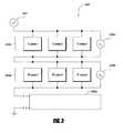
- FIG. 3is a schematic circuit diagram of an example thermal management system 300 that includes a plurality of TE devices in accordance with certain embodiments described herein.
- the thermal management system 300 in Figure 3also illustrates an example monitoring method to detect failure of a TE device. Diagnosing failure in a TE device of a thermal management system 300 can be measured through monitoring voltages and/or currents of the battery thermal management system 300, either under transient or quasi-steady state conditions. Many other monitoring methods are also possible.
- the electrical configuration of the TE devices of the battery thermal management system 300 illustrated in Figure 3is similar to that illustrated in Figure 1 .
- the battery thermal management system 300includes a plurality of TE devices includes a first TE group 304a and a second TE group 304b.
- the TE devices of the first TE group 304aare in parallel electrical communication with one another, and the TE devices of the second TE group 304b are in parallel electrical communication with one another.
- TE device 1, TE device 2, and TE device 3are in parallel electrical communication with one another and TE device 4, TE device 5, and TE device 6 are in parallel electrical communication with one another.
- the first TE group 304a and the second TE group 304bare in series electrical communication with one another.
- One or more additional TE groups 304ccan also be placed in series electrical communication with the first TE group 304a and the second TE group 304b.
- a method of thermally managing a battery system 300includes providing a battery system comprising at least one battery and a plurality of thermoelectric devices in thermal communication with the at least one battery.
- the plurality of thermoelectric devicesincludes a first group 304a of thermoelectric devices in series electrical communication with a second group 304b of thermoelectric devices.
- the methodincludes measuring a first electrical voltage or current of the first group 304a and measuring a second electrical voltage or current of the second group 304b or both the first group 304a and second group 304b together.
- the methodfurther includes monitoring an electrical comparison parameter dependent on the first electrical voltage or current and the second electrical voltage or current.
- the electrical comparison parametercomprises a value of the first electrical voltage or current divided by the second electrical voltage or current.
- the methodfurther includes changing, in response to the electrical comparison parameter, at least one parameter of the battery system.
- the at least one parametercan be, for example, electrical power supplied to the plurality of thermoelectric devices.
- the thermal management system 300can include two or more voltage and/or current meters for measuring the electrical voltage or current.
- a first meter 306acan measure a first voltage and/or current (V 1 ) across the first group 304a
- a second meter 306bcan measure a second voltage and/or current (V 2 ) across the second group 304b.
- a system meter 302can measure a system voltage and/or current (V + ) across the first TE group 304a, the second group 304b, and the one or more additional TE groups 304c.
- the ratio of V 1 /V 2 , V 1 /V + or V 2 /V +will change if one or more TE devices fail.
- V 1 /V 2 , V 1 /V + , and V 2 /V +would remain constant if one or more TE devices does not fail. Therefore, by monitoring V 1 and V 2 or V + , a failure of a TE device can be detected.
- FIG. 4Aillustrates an example battery thermal management system 400 in accordance with certain embodiments described herein.
- a battery thermal management system 400includes at least one battery 402a-d and at least one thermoelectric device 404 in thermal communication with the at least one battery 402a-d.
- the battery thermal management system 400can include at least one first conduit 406 that includes at least one inlet 408 configured to allow a first working fluid to enter and flow into the at least one first conduit 406 and into thermal communication with the at least one thermoelectric module 404.
- a heat exchanger 428can transfer heat between the at least one thermoelectric module 404 and the first working fluid.
- the at least one first conduit 406also includes at least one outlet 410 configured to allow the first working fluid to exit and flow from the at least one first conduit 406 and away from being in thermal communication with the at least one thermoelectric module 404.
- the battery thermal management system 400can further include at least one first flow control device 412 which directs the first working fluid through the at least one inlet 408 of the at least one first conduit 406, and at least one second flow control device 414 which directs the first working fluid through the at least one outlet 410 of the at least one first conduit 406.
- the at least one first flow control device 412 and the at least one second flow control device 414are each separately operable from one another.
- the at least one first flow control device 412pushes the first working fluid while the at least one second flow control device 414 pulls the first working fluid
- the at least one first flow control device 412 and the at least one second flow control device 414are in series with one another or are in a push/pull configuration.
- the arrows in Figure 4Aillustrate the direction of flow of the working fluid.
- the at least one first control device 412is positioned at an entrance of the at least one inlet 408 and the at least one second control device 414 is positioned at an exit of the at least one outlet 410.
- the at least one first control device 412is configured to push the first working fluid through the at least one inlet 408 and the at least one second control device 414 is configured to pull the first working fluid through at least one outlet 410.
- the battery thermal management system 400further includes a flow path for the first working fluid in which the first working fluid is in thermal communication with the at least one battery. The flow path, in some embodiments, receives the first working fluid from the at least one outlet 408.
- the first working fluidis substantially thermally or electrically isolated from the at least one battery.
- the thermoelectric module 404can include two sides including a cooler side and a hotter side. The first working fluid can be in thermal communication with only the cooler side or the hotter side, and the first working fluid can be substantially thermally isolated from the other side.
- the battery thermal management system 400includes at least one second conduit 416 including at least one inlet 418 configured to allow a second working fluid to enter and flow into the at least one second conduit 416 and into thermal communication with the at least one thermoelectric device 404.
- a heat exchanger 426can transfer heat between the at least one thermoelectric device 404 and the second working fluid.
- the at least one second conduit 416includes at least one outlet 420 configured to allow the second working fluid to exit and flow from the at least one second conduit 416 and away from being in thermal communication with the at least one thermoelectric device 404.
- the battery thermal management system 400includes at least one third flow control device 422 which directs the second working fluid through the at least one inlet 418 of the at least one second conduit 416, and at least one fourth flow control device 424 which directs the second working fluid through the at least one outlet 420 of the at least one second conduit 416.
- the at least one third first flow control device 422 and the at least one fourth flow control device 424are each separately operable from one another.
- the arrows in Figure 4Aillustrate the direction of flow of the first working fluid and the second working fluid.
- the first working fluidis substantially thermally isolated from the second working fluid.
- the first working fluidcan be in thermal communication with a first side of the TE device 404 and the at least one battery 402a-d
- the second working fluidcan be in thermal communication with a second side of the TE device 404 different from the first side.
- the at least one battery 402a-dcan be selectively heated or cooled and the first working fluid and second working fluid can be correspondingly heated or cooled.
- the first side of the TE device 404can be selected to heat or cool the at least one battery 402a-d by heating or cooling the first working fluid and transferring heat between the at least one battery 402a-d and the first working fluid, and the second working fluid can be correspondingly cooled if the first working fluid is heated or heated if the first working fluid is cooled.
- a method of thermally managing a battery thermal management system 400includes transferring heat between at least one battery 402a-d and at least one thermoelectric device 404 and flowing a working fluid through a fluid conduit 406 in thermal communication with the at least one thermoelectric device 404.
- the methodfurther includes operating at least one first flow control device 412 to direct the working fluid to be in thermal communication with the at least one thermoelectric device 404 and operating at least one second flow control device 414 to direct the working fluid away from being in thermal communication with the at least one thermoelectric device 404.
- the working fluidflows past, along, or around the at least one battery 402a-d and heat is transferred from or to the at least one battery 402a-d.
- the at least one battery 402a-dis in substantially direct thermal communication with the TE device 404 and a working fluid does not transfer heat between the at least one battery 402a-d and the TE device.
- the working fluidis substantially thermally isolated from the at least one battery 402a-d and heat is transferred between the TE device 404 and working fluid.
- the working fluidcan transfer waste heat away from the TE device 404.
- Figure 4Billustrates a fluid conduit 450 of a battery thermal management system in accordance with certain embodiments described herein.
- Figure 4Bis an example of flow control devices working in parallel while Figure 4A is an example of flow control devices working in series.
- a battery thermal management systemincludes at least one battery and at least one thermoelectric module 452 in thermal communication with the at least one battery.
- the battery thermal management systemfurther includes at least one fluid conduit 450 configured to allow a working fluid to flow therein and to transfer the working fluid into being in thermal communication with the at least one thermoelectric module 452 or away from being in thermal communication with the at least one thermoelectric module 452.
- At least one first flow control device 454directs the working fluid through the at least one fluid conduit 450
- at least one second flow control device 456directs the working fluid through the at least one fluid conduit 450.
- the at least one first flow control device 454 and the at least one second flow control device 456are each separately operable from one another.
- the battery thermal management systemalso includes at least one divider portion 458 that is selectively positionable to block the working fluid from flowing between the at least one fluid conduit 450 and a selected one of the at least one first flow control device 454 and the at least one second flow control device 456.
- a divider wall 460can separate the at least one fluid conduit 450
- a flapper valve 462can be positioned to block flow of the working fluid through either the first flow control device 454 or the at least one second flow control device 456.
- the dotted line in Figure 4Billustrates the flapper valve 462 blocking the flow through the at least one second flow control device 456, and the arrow illustrates how the flapper valve 462 can rotate to block the flow of the working fluid from flowing through the at least one second flow control device 456.
- the flapper valve 462prevents back flow of the working fluid through an inoperative flow control device.
- the other arrows in Figure 4Billustrate the direction of flow of the working fluid.
- the at least one divider portion 458is positionable in multiple positions including: (1) a first position permitting the working fluid to flow between the at least one fluid conduit 450 and the at least one first flow control device 454 and permitting the working fluid to flow between the at least one fluid conduit 450 and the at least one second flow control device 456, (2) a second position permitting the working fluid to flow between the at least one fluid conduit 450 and the at least one first flow control device 454 and blocking the working fluid from flowing between the at least one fluid conduit 450 and the at least one second flow control device 456, and (3) a third position blocking the working fluid from flowing between the at least one fluid conduit 450 and the at least one first flow control device 454 and permitting the working fluid to flow between the at least one fluid conduit 450 and the at least one second flow control device 458.
- the battery thermal management systemcan include both flow control devices in series and parallel.
- the at least one first flow control device 412 in Figure 4Acan include at least two first flow control devices.
- the battery thermal management system 400can include at least one divider portion that is selectively positionable to block the working fluid from flowing between the at least one first fluid conduit 406 and a selected one of the at least one first flow control devices 412.
- the divider portionseparates at least a portion of the at least one inlet or the at least one outlet into at least two fluid channels comprising a first fluid channel and a second fluid channel.
- At least one flow control device of the at least two first flow control devices 412directs the first working fluid through a first fluid channel, and at least one other flow control device of the at least two first flow control devices directs the first working fluid through a second fluid channel.
- Each of the at least two first flow control devicesare each separately operable from one another.
- a method of thermally managing a battery systemincludes transferring heat between at least one battery and at least one thermoelectric device 452 and flowing a working fluid through a fluid conduit 450 in thermal communication with at least one thermoelectric device 452. The method further includes directing the working fluid through the fluid conduit 450 using at least one first flow control device 454 and at least one second flow control device 456 and selectively inhibiting flow of the working fluid through a selected one of the at least one first flow control device 454 and the at least one second flow control device 456.
- the battery thermal management systemincludes a plurality of power lines and/or redundancy with the power source or supply.
- the power supplycan have several power conversion phases and energy filtering and/or storage components.
- Other methods of providing electrical power redundancymay also be provided. While performance such as ripple or drop out may occur as the result of a single failure, cooling or heating can continue to be provided.
- the TE deviceis put in close proximity to the battery.
- TE devicemay be attached, coupled, or integrated with the battery or a battery case.
- the cooling or heating side of a TE devicecan be advantageously positioned as close to the battery as possible.
- the cooling or heating power that may be lost through ducts or insulationcan directly condition the system. Conditioning can include transferring heat to the battery to increase the temperature of the battery or transferring heat from the battery to decrease the temperature of the battery.
- the thermal power generated that leaks out of at least a portion of the ducts, conduits, or other mechanisms that direct a conditioned working fluidoften still can be at least partially utilized.
- the conditioning surfacessuch as ducts, tubes, etc. are positioned generally toward the working fluid, battery, or volume to be cooled, and the heat rejection side generally away from the conditioned surfaces and area.
- FIG. 7illustrates an example battery thermal management system 700 that includes at least one conduit 760 (e.g. fluid circuit) in accordance with certain embodiments described herein.
- the battery thermal management system 700includes at least one battery 702a-d and at least one thermoelectric device 704 in thermal communication with the at least one battery 702a-d.
- the battery thermal management system 700includes at least one flow control device 740 such as a fluid pump.
- the at least one flow control device 740circulates the working fluid through the at least one conduit 760.
- the working fluidis re-circulated through the at least one conduit 760.
- the working fluidmay flow into thermal communication with the at least one thermoelectric device 704, and the working fluid may flow away from being in thermal communication with the at least one thermoelectric device 704.
- At least one heat exchanger 726may be in thermal communication with the at least one thermoelectric device 704.
- the working fluidmay flow into thermal communication with the at least one heat exchanger 726 and the working fluid may flow away from being in thermal communication with the at least one heat exchanger 726.
- the same working fluidmay flow into and away from being in thermal communication with the at least one thermoelectric device 704 more than once.
- the at least one conduit 760can be a fluid loop.
- the battery thermal management system 700includes a fluid reservoir or source 750 fluidly coupled with the at least one conduit 760.
- the fluid reservoir or source 750may heat or cool the working fluid.
- the fluid reservoir or source 750can be connected to other sources of heat such as an engine powertrain fluid to provide further heat to the at least one battery 702a-d.
- the fluid reservoir or source 750can include a radiator such as a vehicle chassis or an auxiliary radiator to reject heat from the at least one battery 702a-d through the at least one TE device 704.
- the working fluidcan be any type of fluid such as liquid, gas, or multipurpose solid-liquid convection medium.
- the working fluidcomprises a mixture of water and glycol.
- a liquid working fluidmay have a greater thermal capacity than a gas working fluid, which can result in greater efficiency for the TE device 704.
- many heat exchangers with fins, etc.have a higher thermal coefficient of performance or a higher heat transfer rate with the working fluid when the working fluid is a liquid than when the working fluid is a gas (e.g., air).
- a higher thermal coefficient of performancecan reduce the temperature drop across the interface between the working fluid and the heat exchanger 726.
- the total temperature drop between the TE device 704 and the working fluidcan be reduced.
- a lower temperature dropcan result in higher efficiency for the TE device 704 and/or higher temperature differential across the TE device 704.
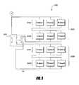
- FIG. 5is a schematic circuit diagram of an example thermal management system 500 comprising a plurality of TE devices configured to change thermal power output by changing the electrical configuration of the TE devices in accordance with certain embodiments described herein. For example, under extreme ambient heat (or cold), it may be desirable to increase the current through the TE devices to increase cooling (or heating) thermal power output.
- the TE devicescan be TE elements, TE assemblies, or TE modules.
- At battery thermal management system 500includes at least one battery and a plurality of thermoelectric assemblies 502a, 502b in thermal communication with the at least one battery.
- Each thermoelectric assembly 502a, 502bincludes a plurality of thermoelectric devices.
- a first thermoelectric assembly 502a of the plurality of thermoelectric assembliesis in electrical communication with a second thermoelectric assembly 502b of the plurality of thermoelectric assemblies.
- a circuit 506is in electrical communication with the first thermoelectric assembly 502a and the second thermoelectric assembly 502b.
- the circuit 506can be configured to be selectively switchable to place the first thermoelectric assembly 502a and the second thermoelectric assembly 502b either in series electrical communication or parallel electrical communication with one another.
- thermoelectric elements of the first thermoelectric assembly 502acan be in series electrical communication and/or in parallel electrical communication with one another
- at least some of the plurality of thermoelectric elements of the second thermoelectric assembly 502bcan be in series electrical communication and/or parallel electrical communication with one another
- the first thermoelectric assembly 502acan include a first plurality of TE groups 504a, 504b
- the second thermoelectric assembly 502bcan include a second plurality of TE groups 504c, 504d.
- a first TE group 504a of TE devicesare in parallel electrical communication with one another
- a second TE group 504b of TE devicesare in parallel electrical communication with one another
- a third TE group 504c of TE devicesare in parallel electrical communication with one another
- a fourth TE group 504d of TE devicesare in parallel electrical communication with one another.
- the first TE group 504ais in parallel electrical communication with the second TE group 504b
- the third group 504cis in parallel electrical communication with the fourth TE group 504d.
- thermoelectric assembly 502acan be configured to be selectively switchable to place the first thermoelectric assembly 502a and the second thermoelectric assembly 502b either in series electrical communication or parallel electrical communication with one another.
- the solid lines in the circuit 506 of Figure 5illustrate a first circuit position wherein the first TE group 504a, the second TE group 504b, the third TE group 504c, and the fourth TE group 504d are in series electrical communication with one another.
- the dotted lines in the circuit 506 of Figure 5illustrate a second circuit position wherein the first TE group 504a is in series electrical communication with the second TE group 504b, the third TE group 504c is in series electrical communication with the fourth TE group 504d, and the first thermoelectric assembly 502a (e.g., the first TE group 504a and the second TE group 504b) is in parallel electrical communication with the second thermoelectric assembly 502b (e.g., the third TE group 504c and the second TE group 504d).
- a method of thermally managing a battery system 500includes providing a battery system including at least one battery and a plurality of thermoelectric assemblies 502a, 502b in thermal communication with the at least one battery. The method further includes measuring at least one parameter of the battery system and switching, in response to the at least one parameter, a first thermoelectric assembly 502a of the plurality of thermoelectric assemblies between being in parallel or series electrical communication with a second thermoelectric assembly 502b of the plurality of thermoelectric assemblies.
- the at least one parametercan, for example, include temperature of the at least one battery and/or the battery system. Additional parameters are discussed in the following sections.
- the plurality of thermoelectric assembliesare selectively operable to either heat or cool the at least one battery.
- the circuit 506may also be selectively switchable to adjust current flow through the first thermoelectric assembly 502a and the second thermoelectric assembly 502b.
- voltage of the circuit 502can be altered to cause more or less current to flow through the TE devices in order to modify heat pumping capacity of the TE devices.
- the performance of the BTMScan be altered by, for example, altering fan and/or pump operation to change working fluid flow conditions such as flow rate and/or flow paths.
- the BTMScan further include a controller to control the circuit 502, flow control devices, etc. of the BTMS.
- the controllermay be integrated with the BTMS or may be an external controller.
- Thermal managementcan be important to the proper operation and life of a battery or battery array, so monitoring temperatures and other parameters to determine the state of operation of the BTMS can be advantageous. Several conditions can also be monitored simultaneously and/or periodically or at various times to assure proper function and address operational discrepancies. Monitoring sensors and devices can be incorporated into the TE devices, fans and/or pumps the electrical circuitry and other parts of the system to provide useful information.
- Figure 6illustrates examples of a plurality of monitoring systems 630a-d and their locations in a BTMS 600 in accordance with certain embodiments described herein.
- a TE device 604can include one or more monitoring systems 630a-d including TE device monitoring systems 630a, battery monitoring systems 630b, working fluid monitoring systems 630c, and flow control device monitoring systems 630d that can measure at least one parameter.
- the monitoring systems 630a-dcan be integrated within, on a surface of, neighboring, or within proximity to measure the at least one parameter of the TE device 604, battery 602a-d, working fluid, flow control device 612, etc.
- componentssuch as fans, circuit elements, battery parts, batteries, components of a battery, battery arrays and/or BTMS can include monitoring systems 630a-d.
- a monitoring system 630a-dcan include one or more temperature sensors. Temperature sensors can include thermistors, positive temperature coefficient-thermal cutoffs, thermocouples and other temperature sensing and temperature activated devices. Temperatures that can be monitored can include, for example, working fluid, inlet fluid temperatures, conditioned fluid temperatures, temperature differentials between fluid inlets and outlets, temperature between the conditioning side and the heat rejection side, fluid control device (e.g., pump or fan) temperatures. Furthermore, multiple measurements at several locations and any other combination of temperature measurements may be made.
- fluid control device speeds, fluid control device voltages and/or currents, fluid flow rates at one or multiple locations, emissions of fluids from the battery, battery array or any other device, fluid velocities, battery voltages and/or currents, battery or battery dimensions and/or dimensional changecan be monitored.
- at least one monitoring systemcan include circuit sensors to monitor electrical communication of circuits and/or TE devices 604.
- Monitoring systemscan also provide a signal or be in communication with a control device.
- the control devicemay measure the at least one parameter that is monitored, and the control device may, in response to the at least one parameter, cause at least one component of the BTMS to change.
- the control devicemay apply an algorithm to the measured parameter to determine what response, if any, the control device may apply to a component of the BTMS.
- Control devicescan include devices that acquire sensor data, perform calculations based on the sensor data, and cause at least one component of the BTMS to change such as valves, blower speed controllers and other devices to actuate or reduce/increase flow rate, etc., and parametric controllers.
- At least one parametercan be monitored to determine the exposure the battery, battery array or BTMS may have experienced and any other operating history of the BTMS that may be useful.
- the monitoringcan be done for warranty, determining charge cycle (e.g., optimizing speed of charge), state of operation, safety, optimizing performance, increasing longevity, establishing operational history, indicating failure, modifying battery charge schedules based on measured values, indicating impending degradation of performance and any other diagnostic measurements.
- the BTMSmay contain control, communication, computational, storage and/or processing capabilities to act upon the information collected by components of the BTMS and/or other systems in communication with the BTMS and communicate results of information processed by the BTMS and/or other systems.
- the BTMSmay contain electronic signal processing hardware, input/output devices, permanent recording hardware or any other useful electronic or other signal processing equipment.
- the systemmay have the capacity to take actions, send signals, receive signals, store information, perform logic functions, control temperatures, fan and/or pump, TE, and any other subsystem function, modify operation and/or perform any other function to manage battery or battery array operation.
Landscapes
- Engineering & Computer Science (AREA)
- Chemical & Material Sciences (AREA)
- Chemical Kinetics & Catalysis (AREA)
- Electrochemistry (AREA)
- General Chemical & Material Sciences (AREA)
- Manufacturing & Machinery (AREA)
- Materials Engineering (AREA)
- Electromagnetism (AREA)
- Physics & Mathematics (AREA)
- Sustainable Development (AREA)
- Life Sciences & Earth Sciences (AREA)
- Sustainable Energy (AREA)
- Power Engineering (AREA)
- Transportation (AREA)
- Mechanical Engineering (AREA)
- Aviation & Aerospace Engineering (AREA)
- Inorganic Chemistry (AREA)
- Automation & Control Theory (AREA)
- Secondary Cells (AREA)
Description
- The present application relates to battery thermal management systems and thermoelectric cooling and heating batteries.
- High performance batteries for use in large systems (including, for example, lithium based batteries used in electrical vehicles) have certain properties that make thermal management of the batteries and/or containment system desirable. Charging characteristics of high performance batteries change at elevated temperatures and can cause the cycle life of the batteries to decrease significantly if they are charged at too high of a temperature. For example, the cycle life of some lithium based batteries decreased by over 50% if they are repeatedly charged at about 50 °C. Since cycle life can be reduced by a large amount, the lifetime cost of batteries can be greatly increased if charging temperatures are not controlled within proper limits. Also, some high performance batteries can exhibit reduced performance and can be possibly damaged if charged or operated at too low of temperatures, such as below about -30 °C. Furthermore, high performance batteries and arrays of high performance batteries can experience thermal events from which the batteries can be permanently damaged or destroyed, and over temperature condition can even result in fires and other safety related events.
- The present invention is directed to a battery thermal management system and a method of thermally managing a battery system as defined in the claims.
- In certain embodiments, a battery thermal management system is provided. The battery thermal management system can include at least one battery and a plurality of thermoelectric assemblies in thermal communication with the at least one battery. Each thermoelectric assembly can include a plurality of thermoelectric elements, and a first thermoelectric assembly of the plurality of thermoelectric assemblies is in electrical communication with a second thermoelectric assembly of the plurality of thermoelectric assemblies. The battery thermal management system can also include a circuit in electrical communication with the first thermoelectric assembly and the second thermoelectric assembly. The circuit can be configured to be selectively switchable to place the first thermoelectric assembly and the second thermoelectric assembly either in series electrical communication or parallel electrical communication with one another.
- In some embodiments, the at least some of the plurality of thermoelectric elements of the first thermoelectric assembly are in series electrical communication with one another and at least some of the plurality of thermoelectric elements of the second thermoelectric assembly are in series electrical communication with one another. In further embodiments, the plurality of thermoelectric assemblies are selectively operable to either heat or cool the at least one battery.
- In certain embodiments, a method of thermally managing a battery system includes providing a battery system comprising at least one battery and a plurality of thermoelectric assemblies in thermal communication with the at least one battery. The method can further include measuring at least one parameter of the battery system and switching, in response to the at least one parameter, a first thermoelectric assembly of the plurality of thermoelectric assemblies between being in parallel or in series electrical communication with a second thermoelectric assembly of the plurality of thermoelectric assemblies. In some embodiments the at least one parameter is a temperature of the at least one battery and/or a temperature of the plurality of thermoelectric assemblies.
- In certain embodiments, a battery thermal management system includes at least one battery, at least one thermoelectric device in thermal communication with the at least one battery, and at least one first conduit comprising at least one inlet configured to allow a first working fluid to enter and flow into the at least one first conduit and into thermal communication with the at least one thermoelectric device. The at least one first conduit further comprises at least one outlet configured to allow the first working fluid to exit and flow from the at least one first conduit and away from being in thermal communication with the at least one thermoelectric device. The battery thermal management system can further include at least one first flow control device which directs the first working fluid through the at least one inlet of the at least one first conduit and at least one second flow control device which directs the first working fluid through the at least one outlet of the at least one first conduit. The at least one first flow control device and the at least one second flow control device are each separately operable from one another.
- In some embodiments, the at least one second conduit comprises at least one inlet configured to allow a second working fluid to enter and flow into the at least one second conduit and into thermal communication with the at least one thermoelectric device. The at least one second conduit comprises at least one outlet configured to allow the second working fluid to exit and flow from the at least one second conduit and away from being in thermal communication with the at least one thermoelectric device. The battery thermal management system can also include at least one third flow control device which directs the second working fluid through the at least one inlet of the at least one second conduit and at least one fourth flow control device which directs the second working fluid through the at least one outlet of the at least one second conduit. The at least third first flow control device and the at least one fourth flow control device can each be separately operable from one another.
- In certain embodiments, a method of thermally managing a battery system includes transferring heat between at least one battery and at least one thermoelectric device, and flowing a working fluid through a fluid conduit in thermal communication with the at least one thermoelectric device. The method can also include operating at least one first flow control device to direct the working fluid to be in thermal communication with the at least one thermoelectric device, and operating at least one second flow control device separately from the operating of the at least one first flow control device to direct the working fluid away from being in thermal communication with the at least one thermoelectric device.
- In certain embodiments, a battery thermal management system includes at least one battery, at least one thermoelectric device in thermal communication with the at least one battery, and at least one fluid conduit configured to allow a working fluid to flow therein and to transfer the working fluid into being in thermal communication with the at least one thermoelectric device or away from being in thermal communication with the at least one thermoelectric device. The battery thermal management system can further include at least one first flow control device which directs the working fluid through the at least one fluid conduit and at least one second flow control device which directs the working fluid through the at least one fluid conduit. The at least one first flow control device and the at least one second flow control device are each separately operable from one another. The battery thermal management system can also include at least one divider portion that is selectively positionable to block the working fluid from flowing between the at least one fluid conduit and a selected one of the at least one first flow control device and the at least one second flow control device.
- In certain embodiments, a method of thermally managing a battery system includes transferring heat between at least one battery and at least one thermoelectric device, and flowing a working fluid through a fluid conduit in thermal communication with at least one thermoelectric device. The method can further include directing the working fluid through the fluid conduit using at least one first flow control device and at least one second flow control device, and selectively inhibiting flow of the working fluid through a selected one of the at least one first flow control device and the at least one second flow control device.
- In certain embodiments, a method of thermally managing a battery system includes providing a battery system comprising at least one battery and a plurality of thermoelectric devices in thermal communication with the at least one battery. The plurality of thermoelectric devices comprise a first group of one or more thermoelectric devices in series electrical communication with a second group of one or more thermoelectric devices. The method can further include measuring a first electrical voltage or current of the first group, measuring a second electrical voltage or current of the second group or of both the first group and the second group together, and monitoring an electrical comparison parameter dependent on the first electrical voltage or current and the second electrical voltage or current.
Figure 1 is a schematic circuit diagram of an example thermal management system including a plurality of TE devices in accordance with certain embodiments described herein;Figure 2 is an illustrative plot of operating electrical current as a function of the efficiency of energy conversion (COP) and the total thermal output of a TE device;Figure 3 is a schematic circuit diagram of an example thermal management system including a plurality of TE devices and voltage meters in accordance with certain embodiments described herein;Figure 4A is an example thermal management system illustrating flow of a working fluid with flow control devices in series in accordance with certain embodiments described herein;Figure 4B is an example thermal management system illustrating flow of a working fluid with flow control devices in parallel in accordance with certain embodiments described herein;Figure 5 is a schematic circuit diagram of an example thermal management system that includes a control that can be configured to be selectively switchable to place two thermoelectric assemblies either in series electrical communication or parallel electrical communication with one another in accordance with certain embodiments described herein;Figure 6 is an example thermal management system that includes monitoring systems to measure at least one parameter in accordance with certain embodiments described herein; andFigure 7 is an example thermal management system that includes a fluid conduit loop in accordance with certain embodiments described herein.- Battery thermal management systems (BTMS) can be used to control temperatures and monitor conditions of batteries and arrays of batteries to prevent battery failure and/or safety related failure. A BTMS can improve the overall conditions of battery operation by both managing the thermal environment and also being sufficiently reliable so that overall system performance is not degraded. For example, a BTMS may not reduce overall system reliability and not increase system operating cost by not including significant additional possible failure mechanisms to the system. Furthermore, the systems can be environmentally friendly and not contain materials that emit greenhouse gases such as refrigerants. environmentally friendly and not contain materials that emit greenhouse gases such as refrigerants.
- A BTMS includes at least one battery or battery array. In certain embodiments, a battery thermal management system can be used to both heat and cool batteries and/or battery arrays. For example, the battery thermal management system can be integrated with the at least one battery, the battery thermal management system can be integrated with an enclosure wherein the at least one battery is contained, or the thermal management system can be positioned in thermal communication with the at least one battery.
- In certain embodiments, a battery thermal management system includes one or more thermoelectric (TE) devices. For example, the battery thermal management system can include a plurality of thermoelectric elements, at least one thermoelectric assembly, and/or at least one thermoelectric module. TE devices are solid state and do not utilize refrigerants to produce cooling, and some TE devices can produce both heating and cooling. Furthermore, battery thermal management systems can include a plurality of TE devices which can be configured to increase reliability over that of a conventional two phase refrigerant system, such as one employing refrigerant 134A.
- A variety of embodiments of battery thermal management systems are described below to illustrate various configurations. The particular embodiments and examples are only illustrative and features described in one embodiment or example may be combined with other features described in other embodiments or examples. Accordingly, the particular embodiments and examples are not intended to be restrictive in any way.
- In certain embodiments, a battery
thermal management system 100 includes at least one battery and a plurality of thermoelectric devices in thermal communication with the at least one battery.Figure 1 is a schematic circuit diagram of an examplethermal management system 100 comprising a plurality of TE devices in accordance with certain embodiments described herein. The TE devices can be TE elements, TE assemblies, and/or TE modules. The plurality of TE devices includes afirst group 104a of TE devices and asecond group 104b of TE devices. The TE devices of thefirst TE group 104a are in parallel electrical communication with one another, and the TE devices of thesecond TE group 104b are in parallel electrical communication with one another. In particular,TE device 1,TE device 2, andTE device 3 are in parallel electrical communication with one another andTE device 4,TE device 5, andTE device 6 are in parallel electrical communication with one another. Thefirst TE group 104a and thesecond TE group 104b are in series electrical communication with one another. One or moreadditional TE groups 104c can also be placed in series electrical communication with thefirst TE group 104a and thesecond TE group 104b. - The battery
thermal management system 100 can improve overall system cooling and heating reliability. First, the TE devices are configured so as to allow redundancy and eliminate common single point failure mechanisms within each TE group. For example, ifTE device 1 fails open such that theTE device 1 is electrically open (e.g., the TE device is unable to pass electrical current), the current is rerouted throughTE device 2 andTE device 3 which are electrically connected in parallel with the failedTE device 1. If three or more TE devices are electrically connected together in parallel, more than one TE device could fail open, and thethermal management system 100 would still operate to provide cooling and/or heating. - In a further example, if
TE device 1 fails closed (e.g., theTE device 1 is more electrically conductive thanTE device 2 and TE device 3), more of the electrical current will flow through the failedTE device 1 thanTE device 2 andTE device 3, and reduce or eliminate the cooling and/or heating of theTE device 2 andTE device 3 in the same parallel electrical connection. TheTE group 2 that is in series electrical communication withTE group 1 will continue to function and provide heating and/or cooling. Failure of a TE device will degrade performance, but with sufficient numbers of TE devices, and the proper operating conditions, thethermal management system 100 can continue to function, albeit at a reduced heating and/or cooling capability if a TE device fails. In arrays larger than illustrated inFigure 1 , performance of athermal management system 100 with one or more failed TE devices can be substantially the same as that of athermal management system 100 without any failed TE devices. Further examples of TE device redundancy are described inU.S. Patent Publication No. 2010/0031987 , which is incorporated herein in its entirety by reference. Figure 2 is a illustrative plot of operating electrical current as a function of the efficiency of energy conversion (COP) and the total thermal output of a TE device (Qc). Points A and A' are near the operating current that optimizes operating efficiency of the TE device (indicated by Point A) so that it will operate near its peak possible efficiency. Points B and B' are a second operating current that is at 1.5 times the operating current of Points A and A', and Points C and C' are at a third operating current 3 times the operating current of Points A and A'. The dashed lines inFigure 2 illustrate positions of the points relative to each other and relative to the x and y axes. If the TE device operates under a lower temperature differential, efficiency will be lower at Points B, B', C, and C', but cooling and/or heating power will be diminished by a relatively small amount so that cooling and/or heating power will remain nearly the same. Furthermore, a TE device can have a thermal output beyond peak operating efficiency by increasing electrical power even though efficiency may decrease.- The change in the operating circuit induced by failure of one or more TE devices can result in a different current-voltage relationship of a battery
thermal management system 300. Thus, for example if one or more TE devices fail, and if current to the batterythermal management system 300 is fixed, a voltage change will be induced, and vice versa, if voltage is fixed, a current change will be induced.Figure 3 is a schematic circuit diagram of an examplethermal management system 300 that includes a plurality of TE devices in accordance with certain embodiments described herein. Thethermal management system 300 inFigure 3 also illustrates an example monitoring method to detect failure of a TE device. Diagnosing failure in a TE device of athermal management system 300 can be measured through monitoring voltages and/or currents of the batterythermal management system 300, either under transient or quasi-steady state conditions. Many other monitoring methods are also possible. - The electrical configuration of the TE devices of the battery
thermal management system 300 illustrated inFigure 3 is similar to that illustrated inFigure 1 . The batterythermal management system 300 includes a plurality of TE devices includes afirst TE group 304a and asecond TE group 304b. The TE devices of thefirst TE group 304a are in parallel electrical communication with one another, and the TE devices of thesecond TE group 304b are in parallel electrical communication with one another. In particular,TE device 1,TE device 2, andTE device 3 are in parallel electrical communication with one another andTE device 4,TE device 5, andTE device 6 are in parallel electrical communication with one another. Thefirst TE group 304a and thesecond TE group 304b are in series electrical communication with one another. One or moreadditional TE groups 304c can also be placed in series electrical communication with thefirst TE group 304a and thesecond TE group 304b. - In certain embodiments, a method of thermally managing a
battery system 300 includes providing a battery system comprising at least one battery and a plurality of thermoelectric devices in thermal communication with the at least one battery. The plurality of thermoelectric devices includes afirst group 304a of thermoelectric devices in series electrical communication with asecond group 304b of thermoelectric devices. The method includes measuring a first electrical voltage or current of thefirst group 304a and measuring a second electrical voltage or current of thesecond group 304b or both thefirst group 304a andsecond group 304b together. The method further includes monitoring an electrical comparison parameter dependent on the first electrical voltage or current and the second electrical voltage or current. In some embodiments, the electrical comparison parameter comprises a value of the first electrical voltage or current divided by the second electrical voltage or current. In further embodiments, the method further includes changing, in response to the electrical comparison parameter, at least one parameter of the battery system. The at least one parameter can be, for example, electrical power supplied to the plurality of thermoelectric devices. - The
thermal management system 300 can include two or more voltage and/or current meters for measuring the electrical voltage or current. For example, afirst meter 306a can measure a first voltage and/or current (V1) across thefirst group 304a, and asecond meter 306b can measure a second voltage and/or current (V2) across thesecond group 304b. Asystem meter 302 can measure a system voltage and/or current (V+) across thefirst TE group 304a, thesecond group 304b, and the one or moreadditional TE groups 304c. The ratio of V1/V2, V1/V+ or V2/V+ will change if one or more TE devices fail. Furthermore, even if the system voltage or current (V+) changes, the ratios V1/V2, V1/V+, and V2/V+ would remain constant if one or more TE devices does not fail. Therefore, by monitoring V1 and V2 or V+, a failure of a TE device can be detected. - Other possible failure modes include those associated with a fluid cooling/heating system. For example, if more than one flow control device (e.g., fan or pump) is used to move a working fluid, reliability can be increase over use of a single flow control device.
Figure 4A illustrates an example batterythermal management system 400 in accordance with certain embodiments described herein. In certain embodiments, a batterythermal management system 400 includes at least onebattery 402a-d and at least onethermoelectric device 404 in thermal communication with the at least onebattery 402a-d. - The battery
thermal management system 400 can include at least onefirst conduit 406 that includes at least oneinlet 408 configured to allow a first working fluid to enter and flow into the at least onefirst conduit 406 and into thermal communication with the at least onethermoelectric module 404. For example, aheat exchanger 428 can transfer heat between the at least onethermoelectric module 404 and the first working fluid. The at least onefirst conduit 406 also includes at least oneoutlet 410 configured to allow the first working fluid to exit and flow from the at least onefirst conduit 406 and away from being in thermal communication with the at least onethermoelectric module 404. The batterythermal management system 400 can further include at least one firstflow control device 412 which directs the first working fluid through the at least oneinlet 408 of the at least onefirst conduit 406, and at least one secondflow control device 414 which directs the first working fluid through the at least oneoutlet 410 of the at least onefirst conduit 406. The at least one firstflow control device 412 and the at least one secondflow control device 414 are each separately operable from one another. In certain embodiments, the at least one firstflow control device 412 pushes the first working fluid while the at least one secondflow control device 414 pulls the first working fluid, and the at least one firstflow control device 412 and the at least one secondflow control device 414 are in series with one another or are in a push/pull configuration. The arrows inFigure 4A illustrate the direction of flow of the working fluid. - In some embodiments, the at least one
first control device 412 is positioned at an entrance of the at least oneinlet 408 and the at least onesecond control device 414 is positioned at an exit of the at least oneoutlet 410. In further embodiments, the at least onefirst control device 412 is configured to push the first working fluid through the at least oneinlet 408 and the at least onesecond control device 414 is configured to pull the first working fluid through at least oneoutlet 410. In certain embodiments, the batterythermal management system 400 further includes a flow path for the first working fluid in which the first working fluid is in thermal communication with the at least one battery. The flow path, in some embodiments, receives the first working fluid from the at least oneoutlet 408. In other embodiments, the first working fluid is substantially thermally or electrically isolated from the at least one battery. For example, thethermoelectric module 404 can include two sides including a cooler side and a hotter side. The first working fluid can be in thermal communication with only the cooler side or the hotter side, and the first working fluid can be substantially thermally isolated from the other side. - In certain embodiments, the battery
thermal management system 400 includes at least onesecond conduit 416 including at least oneinlet 418 configured to allow a second working fluid to enter and flow into the at least onesecond conduit 416 and into thermal communication with the at least onethermoelectric device 404. For example, aheat exchanger 426 can transfer heat between the at least onethermoelectric device 404 and the second working fluid. The at least onesecond conduit 416 includes at least oneoutlet 420 configured to allow the second working fluid to exit and flow from the at least onesecond conduit 416 and away from being in thermal communication with the at least onethermoelectric device 404. The batterythermal management system 400 includes at least one thirdflow control device 422 which directs the second working fluid through the at least oneinlet 418 of the at least onesecond conduit 416, and at least one fourthflow control device 424 which directs the second working fluid through the at least oneoutlet 420 of the at least onesecond conduit 416. The at least one third firstflow control device 422 and the at least one fourthflow control device 424 are each separately operable from one another. - The arrows in
Figure 4A illustrate the direction of flow of the first working fluid and the second working fluid. In certain embodiments, the first working fluid is substantially thermally isolated from the second working fluid. For example, the first working fluid can be in thermal communication with a first side of theTE device 404 and the at least onebattery 402a-d, and the second working fluid can be in thermal communication with a second side of theTE device 404 different from the first side. Furthermore, the at least onebattery 402a-d can be selectively heated or cooled and the first working fluid and second working fluid can be correspondingly heated or cooled. For example, the first side of theTE device 404 can be selected to heat or cool the at least onebattery 402a-d by heating or cooling the first working fluid and transferring heat between the at least onebattery 402a-d and the first working fluid, and the second working fluid can be correspondingly cooled if the first working fluid is heated or heated if the first working fluid is cooled. - In certain embodiments, a method of thermally managing a battery
thermal management system 400 includes transferring heat between at least onebattery 402a-d and at least onethermoelectric device 404 and flowing a working fluid through afluid conduit 406 in thermal communication with the at least onethermoelectric device 404. The method further includes operating at least one firstflow control device 412 to direct the working fluid to be in thermal communication with the at least onethermoelectric device 404 and operating at least one secondflow control device 414 to direct the working fluid away from being in thermal communication with the at least onethermoelectric device 404. In some embodiments, the working fluid flows past, along, or around the at least onebattery 402a-d and heat is transferred from or to the at least onebattery 402a-d. In other embodiments, the at least onebattery 402a-d is in substantially direct thermal communication with theTE device 404 and a working fluid does not transfer heat between the at least onebattery 402a-d and the TE device. In some embodiments, the working fluid is substantially thermally isolated from the at least onebattery 402a-d and heat is transferred between theTE device 404 and working fluid. For example, the working fluid can transfer waste heat away from theTE device 404. Figure 4B illustrates afluid conduit 450 of a battery thermal management system in accordance with certain embodiments described herein. For comparison,Figure 4B is an example of flow control devices working in parallel whileFigure 4A is an example of flow control devices working in series. In certain embodiments, a battery thermal management system includes at least one battery and at least onethermoelectric module 452 in thermal communication with the at least one battery. The battery thermal management system further includes at least onefluid conduit 450 configured to allow a working fluid to flow therein and to transfer the working fluid into being in thermal communication with the at least onethermoelectric module 452 or away from being in thermal communication with the at least onethermoelectric module 452. At least one firstflow control device 454 directs the working fluid through the at least onefluid conduit 450, and at least one secondflow control device 456 directs the working fluid through the at least onefluid conduit 450. The at least one firstflow control device 454 and the at least one secondflow control device 456 are each separately operable from one another.- The battery thermal management system also includes at least one
divider portion 458 that is selectively positionable to block the working fluid from flowing between the at least onefluid conduit 450 and a selected one of the at least one firstflow control device 454 and the at least one secondflow control device 456. For example, adivider wall 460 can separate the at least onefluid conduit 450, and aflapper valve 462 can be positioned to block flow of the working fluid through either the firstflow control device 454 or the at least one secondflow control device 456. The dotted line inFigure 4B illustrates theflapper valve 462 blocking the flow through the at least one secondflow control device 456, and the arrow illustrates how theflapper valve 462 can rotate to block the flow of the working fluid from flowing through the at least one secondflow control device 456. Theflapper valve 462 prevents back flow of the working fluid through an inoperative flow control device. The other arrows inFigure 4B illustrate the direction of flow of the working fluid. - In certain embodiments, the at least one
divider portion 458 is positionable in multiple positions including: (1) a first position permitting the working fluid to flow between the at least onefluid conduit 450 and the at least one firstflow control device 454 and permitting the working fluid to flow between the at least onefluid conduit 450 and the at least one secondflow control device 456, (2) a second position permitting the working fluid to flow between the at least onefluid conduit 450 and the at least one firstflow control device 454 and blocking the working fluid from flowing between the at least onefluid conduit 450 and the at least one secondflow control device 456, and (3) a third position blocking the working fluid from flowing between the at least onefluid conduit 450 and the at least one firstflow control device 454 and permitting the working fluid to flow between the at least onefluid conduit 450 and the at least one secondflow control device 458. - In some embodiments, the battery thermal management system can include both flow control devices in series and parallel. For example, the at least one first
flow control device 412 inFigure 4A can include at least two first flow control devices. Furthermore, the batterythermal management system 400 can include at least one divider portion that is selectively positionable to block the working fluid from flowing between the at least one firstfluid conduit 406 and a selected one of the at least one firstflow control devices 412. In certain embodiments, the divider portion separates at least a portion of the at least one inlet or the at least one outlet into at least two fluid channels comprising a first fluid channel and a second fluid channel. At least one flow control device of the at least two firstflow control devices 412 directs the first working fluid through a first fluid channel, and at least one other flow control device of the at least two first flow control devices directs the first working fluid through a second fluid channel. Each of the at least two first flow control devices are each separately operable from one another. - In certain embodiments, a method of thermally managing a battery system includes transferring heat between at least one battery and at least one
thermoelectric device 452 and flowing a working fluid through afluid conduit 450 in thermal communication with at least onethermoelectric device 452. The method further includes directing the working fluid through thefluid conduit 450 using at least one firstflow control device 454 and at least one secondflow control device 456 and selectively inhibiting flow of the working fluid through a selected one of the at least one firstflow control device 454 and the at least one secondflow control device 456. - The reliability of the electrical power provided by the BTMS can also be improved. In certain embodiments, the battery thermal management system includes a plurality of power lines and/or redundancy with the power source or supply. For example, the power supply can have several power conversion phases and energy filtering and/or storage components. Other methods of providing electrical power redundancy may also be provided. While performance such as ripple or drop out may occur as the result of a single failure, cooling or heating can continue to be provided.
- In certain embodiments, the TE device is put in close proximity to the battery. For example, TE device may be attached, coupled, or integrated with the battery or a battery case. To improve efficiency of the BTMS, increase heating and/or cooling capacity, and/or increase temperature control uniformity across a battery, the cooling or heating side of a TE device can be advantageously positioned as close to the battery as possible. Furthermore, the cooling or heating power that may be lost through ducts or insulation can directly condition the system. Conditioning can include transferring heat to the battery to increase the temperature of the battery or transferring heat from the battery to decrease the temperature of the battery. As a result, the thermal power generated that leaks out of at least a portion of the ducts, conduits, or other mechanisms that direct a conditioned working fluid, often still can be at least partially utilized. Thus, in certain embodiments, the conditioning surfaces such as ducts, tubes, etc. are positioned generally toward the working fluid, battery, or volume to be cooled, and the heat rejection side generally away from the conditioned surfaces and area.
Figure 7 illustrates an example batterythermal management system 700 that includes at least one conduit 760 (e.g. fluid circuit) in accordance with certain embodiments described herein. The batterythermal management system 700 includes at least one battery 702a-d and at least onethermoelectric device 704 in thermal communication with the at least one battery 702a-d. The batterythermal management system 700 includes at least oneflow control device 740 such as a fluid pump. The at least oneflow control device 740 circulates the working fluid through the at least oneconduit 760. In some embodiments, the working fluid is re-circulated through the at least oneconduit 760. The working fluid may flow into thermal communication with the at least onethermoelectric device 704, and the working fluid may flow away from being in thermal communication with the at least onethermoelectric device 704. For example, at least oneheat exchanger 726 may be in thermal communication with the at least onethermoelectric device 704. The working fluid may flow into thermal communication with the at least oneheat exchanger 726 and the working fluid may flow away from being in thermal communication with the at least oneheat exchanger 726. The same working fluid may flow into and away from being in thermal communication with the at least onethermoelectric device 704 more than once. For example, the at least oneconduit 760 can be a fluid loop.- In certain embodiments, the battery
thermal management system 700 includes a fluid reservoir orsource 750 fluidly coupled with the at least oneconduit 760. The fluid reservoir orsource 750 may heat or cool the working fluid. For example, the fluid reservoir orsource 750 can be connected to other sources of heat such as an engine powertrain fluid to provide further heat to the at least one battery 702a-d. In another example, the fluid reservoir orsource 750 can include a radiator such as a vehicle chassis or an auxiliary radiator to reject heat from the at least one battery 702a-d through the at least oneTE device 704. - The working fluid can be any type of fluid such as liquid, gas, or multipurpose solid-liquid convection medium. In certain embodiments, the working fluid comprises a mixture of water and glycol. A liquid working fluid may have a greater thermal capacity than a gas working fluid, which can result in greater efficiency for the
TE device 704. In particular, many heat exchangers with fins, etc. have a higher thermal coefficient of performance or a higher heat transfer rate with the working fluid when the working fluid is a liquid than when the working fluid is a gas (e.g., air). A higher thermal coefficient of performance can reduce the temperature drop across the interface between the working fluid and theheat exchanger 726. Thus, the total temperature drop between theTE device 704 and the working fluid can be reduced. A lower temperature drop can result in higher efficiency for theTE device 704 and/or higher temperature differential across theTE device 704. - The thermal output of a BTMS may be varied to accommodate various conditions, including operation in extreme environments.
Figure 5 is a schematic circuit diagram of an examplethermal management system 500 comprising a plurality of TE devices configured to change thermal power output by changing the electrical configuration of the TE devices in accordance with certain embodiments described herein. For example, under extreme ambient heat (or cold), it may be desirable to increase the current through the TE devices to increase cooling (or heating) thermal power output. The TE devices can be TE elements, TE assemblies, or TE modules. - In certain embodiments, at battery
thermal management system 500 includes at least one battery and a plurality ofthermoelectric assemblies thermoelectric assembly thermoelectric assembly 502a of the plurality of thermoelectric assemblies is in electrical communication with a secondthermoelectric assembly 502b of the plurality of thermoelectric assemblies. Acircuit 506 is in electrical communication with the firstthermoelectric assembly 502a and the secondthermoelectric assembly 502b. Thecircuit 506 can be configured to be selectively switchable to place the firstthermoelectric assembly 502a and the secondthermoelectric assembly 502b either in series electrical communication or parallel electrical communication with one another. - In some embodiments, at least some of the plurality of thermoelectric elements of the first
thermoelectric assembly 502a can be in series electrical communication and/or in parallel electrical communication with one another, and at least some of the plurality of thermoelectric elements of the secondthermoelectric assembly 502b can be in series electrical communication and/or parallel electrical communication with one another. For example, the firstthermoelectric assembly 502a can include a first plurality ofTE groups thermoelectric assembly 502b can include a second plurality ofTE groups Figure 5 , afirst TE group 504a of TE devices are in parallel electrical communication with one another, asecond TE group 504b of TE devices are in parallel electrical communication with one another, athird TE group 504c of TE devices are in parallel electrical communication with one another, and afourth TE group 504d of TE devices are in parallel electrical communication with one another. Thefirst TE group 504a is in parallel electrical communication with thesecond TE group 504b, and thethird group 504c is in parallel electrical communication with thefourth TE group 504d. Similar features as discussed with regard toFigure 1 can be included with certain embodiments that include acircuit 506 that can be configured to be selectively switchable to place the firstthermoelectric assembly 502a and the secondthermoelectric assembly 502b either in series electrical communication or parallel electrical communication with one another. - The solid lines in the
circuit 506 ofFigure 5 illustrate a first circuit position wherein thefirst TE group 504a, thesecond TE group 504b, thethird TE group 504c, and thefourth TE group 504d are in series electrical communication with one another. The dotted lines in thecircuit 506 ofFigure 5 illustrate a second circuit position wherein thefirst TE group 504a is in series electrical communication with thesecond TE group 504b, thethird TE group 504c is in series electrical communication with thefourth TE group 504d, and the firstthermoelectric assembly 502a (e.g., thefirst TE group 504a and thesecond TE group 504b) is in parallel electrical communication with the secondthermoelectric assembly 502b (e.g., thethird TE group 504c and thesecond TE group 504d). - In certain embodiments, a method of thermally managing a
battery system 500 includes providing a battery system including at least one battery and a plurality ofthermoelectric assemblies thermoelectric assembly 502a of the plurality of thermoelectric assemblies between being in parallel or series electrical communication with a secondthermoelectric assembly 502b of the plurality of thermoelectric assemblies. The at least one parameter can, for example, include temperature of the at least one battery and/or the battery system. Additional parameters are discussed in the following sections. - In some embodiments, the plurality of thermoelectric assemblies are selectively operable to either heat or cool the at least one battery. The
circuit 506 may also be selectively switchable to adjust current flow through the firstthermoelectric assembly 502a and the secondthermoelectric assembly 502b. Furthermore, voltage of the circuit 502 can be altered to cause more or less current to flow through the TE devices in order to modify heat pumping capacity of the TE devices. The performance of the BTMS can be altered by, for example, altering fan and/or pump operation to change working fluid flow conditions such as flow rate and/or flow paths. The BTMS can further include a controller to control the circuit 502, flow control devices, etc. of the BTMS. The controller may be integrated with the BTMS or may be an external controller. - Thermal management can be important to the proper operation and life of a battery or battery array, so monitoring temperatures and other parameters to determine the state of operation of the BTMS can be advantageous. Several conditions can also be monitored simultaneously and/or periodically or at various times to assure proper function and address operational discrepancies. Monitoring sensors and devices can be incorporated into the TE devices, fans and/or pumps the electrical circuitry and other parts of the system to provide useful information.
Figure 6 illustrates examples of a plurality ofmonitoring systems 630a-d and their locations in aBTMS 600 in accordance with certain embodiments described herein. - A
TE device 604 can include one ormore monitoring systems 630a-d including TEdevice monitoring systems 630a,battery monitoring systems 630b, workingfluid monitoring systems 630c, and flow controldevice monitoring systems 630d that can measure at least one parameter. Themonitoring systems 630a-d can be integrated within, on a surface of, neighboring, or within proximity to measure the at least one parameter of theTE device 604,battery 602a-d, working fluid,flow control device 612, etc. For example, components such as fans, circuit elements, battery parts, batteries, components of a battery, battery arrays and/or BTMS can includemonitoring systems 630a-d. - A
monitoring system 630a-d can include one or more temperature sensors. Temperature sensors can include thermistors, positive temperature coefficient-thermal cutoffs, thermocouples and other temperature sensing and temperature activated devices. Temperatures that can be monitored can include, for example, working fluid, inlet fluid temperatures, conditioned fluid temperatures, temperature differentials between fluid inlets and outlets, temperature between the conditioning side and the heat rejection side, fluid control device (e.g., pump or fan) temperatures. Furthermore, multiple measurements at several locations and any other combination of temperature measurements may be made. - In addition to temperature, fluid control device speeds, fluid control device voltages and/or currents, fluid flow rates at one or multiple locations, emissions of fluids from the battery, battery array or any other device, fluid velocities, battery voltages and/or currents, battery or battery dimensions and/or dimensional change can be monitored. Furthermore, at least one monitoring system can include circuit sensors to monitor electrical communication of circuits and/or
TE devices 604. - Monitoring systems can also provide a signal or be in communication with a control device. In some embodiments, the control device may measure the at least one parameter that is monitored, and the control device may, in response to the at least one parameter, cause at least one component of the BTMS to change. For example, the control device may apply an algorithm to the measured parameter to determine what response, if any, the control device may apply to a component of the BTMS. Control devices can include devices that acquire sensor data, perform calculations based on the sensor data, and cause at least one component of the BTMS to change such as valves, blower speed controllers and other devices to actuate or reduce/increase flow rate, etc., and parametric controllers.
- In addition, at least one parameter (e.g., a signal) can be monitored to determine the exposure the battery, battery array or BTMS may have experienced and any other operating history of the BTMS that may be useful. The monitoring can be done for warranty, determining charge cycle (e.g., optimizing speed of charge), state of operation, safety, optimizing performance, increasing longevity, establishing operational history, indicating failure, modifying battery charge schedules based on measured values, indicating impending degradation of performance and any other diagnostic measurements.
- In addition to the components, sensors, functions, etc. discussed above, the BTMS may contain control, communication, computational, storage and/or processing capabilities to act upon the information collected by components of the BTMS and/or other systems in communication with the BTMS and communicate results of information processed by the BTMS and/or other systems. Thus, the BTMS may contain electronic signal processing hardware, input/output devices, permanent recording hardware or any other useful electronic or other signal processing equipment. The system may have the capacity to take actions, send signals, receive signals, store information, perform logic functions, control temperatures, fan and/or pump, TE, and any other subsystem function, modify operation and/or perform any other function to manage battery or battery array operation.
- Various embodiments have been described above. Although the invention has been described with reference to these specific embodiments, the descriptions are intended to be illustrative and are not intended to be limiting. Various modifications and applications may occur to those skilled in the art without departing from the scope of the invention as defined in the appended claims.
Claims (16)
- A battery thermal management system comprising:at least one battery;a plurality of thermoelectric assemblies in thermal communication with the at least one battery, each thermoelectric assembly comprising a plurality of thermoelectric elements, wherein a first thermoelectric assembly of the plurality of thermoelectric assemblies is in electrical communication with a second thermoelectric assembly of the plurality of thermoelectric assemblies; anda circuit in electrical communication with the first thermoelectric assembly and the second thermoelectric assembly, the circuit configured to be selectively switchable to place the first thermoelectric assembly and the second thermoelectric assembly either in series electrical communication or parallel electrical communication with one another.
- The battery thermal management system of Claim 1, wherein at least some of the plurality of thermoelectric elements of the first thermoelectric assembly are in series electrical communication with one another and at least some of the plurality of thermoelectric elements of the second thermoelectric assembly are in series electrical communication with one another.
- The battery thermal management system of Claim 1 or Claim 2, wherein the plurality of thermoelectric assemblies are selectively operable to either heat or cool the at least one battery.
- The battery thermal management system of any one of Claims 1-3, wherein the circuit is selectively switchable to adjust current flow through the first thermoelectric assembly and the second thermoelectric assembly.
- The battery thermal management system of any one of Claims 1-4, wherein at least some of the plurality of thermoelectric elements of the first thermoelectric assembly are in parallel or series electrical communication with one another.
- The battery thermal management system of any one of Claims 1-5, further comprising a controller configured to control the circuit.
- The battery thermal management system of any one of Claims 1-6, further comprising a monitor configured to monitor at least one parameter.
- The battery thermal management system of Claim 7, wherein the at least one parameter comprises a temperature of the at least one battery.
- The battery thermal management system of any one of Claims 1-8,
wherein the first thermoelectric assembly comprises at least a first group of thermoelectric devices and a second group of thermoelectric devices, wherein the thermoelectric devices of the first group are in parallel electrical communication with one another and the thermoelectric devices of the second group are in parallel electrical communication with one another,
wherein the second thermoelectric assembly comprises at least a third group of thermoelectric devices and a fourth group of thermoelectric devices, wherein the thermoelectric devices of the third group are in parallel electrical communication with one another and the thermoelectric devices of the fourth group are in parallel electrical communication with one another; and
wherein the first group of thermoelectric devices is in series electrical communication with the second group of thermoelectric devices and the third group of thermoelectric devices is in series electrical communication with the fourth group of thermoelectric devices. - A method of thermally managing a battery system, comprising:providing a battery system comprising at least one battery and a plurality of thermoelectric assemblies in thermal communication with the at least one battery;measuring at least one parameter of the battery system; andswitching, in response to the at least one parameter, a first thermoelectric assembly of the plurality of thermoelectric assemblies between being in parallel or in series electrical communication with a second thermoelectric assembly of the plurality of thermoelectric assemblies.
- The method of Claim 10, wherein the at least one parameter comprises a temperature of the at least one battery.
- The method of Claim 10 or Claim 11, wherein the at least one parameter comprises a temperature of at least one of the plurality of thermoelectric assemblies.
- The method of any one of Claims 10-12, wherein the at least one parameter is whether a thermoelectric element of the plurality of thermoelectric assemblies has failed.
- The method of any one of Claims 10-13, wherein the first thermoelectric assembly comprises a plurality of thermoelectric elements, at least some of the plurality of thermoelectric elements of the first thermoelectric assembly are in parallel or series electrical communication with one another.
- The method of any one of Claims 10-14, wherein the plurality of thermoelectric assemblies are selectively operable to either heat or cool the at least one battery.
- The method of any one of Claims 10-15, further comprising:flowing a working fluid through a fluid conduit in thermal communication with at least one of the plurality of thermoelectric assemblies;operating at least one first flow control device to direct the working fluid to be in thermal communication with the at least one of the plurality of thermoelectric assemblies; andoperating at least one second flow control device separately from the operating of the at least one first flow control device to direct the working fluid away from being in thermal communication with the at least one of the plurality of thermoelectric assemblies.
Applications Claiming Priority (2)
| Application Number | Priority Date | Filing Date | Title |
|---|---|---|---|
| US17932609P | 2009-05-18 | 2009-05-18 | |
| PCT/US2010/035321WO2010135371A2 (en) | 2009-05-18 | 2010-05-18 | Battery thermal management system |
Publications (2)
| Publication Number | Publication Date |
|---|---|
| EP2433321A2 EP2433321A2 (en) | 2012-03-28 |
| EP2433321B1true EP2433321B1 (en) | 2014-10-22 |
Family
ID=42320084
Family Applications (1)
| Application Number | Title | Priority Date | Filing Date |
|---|---|---|---|
| EP10721588.1ANot-in-forceEP2433321B1 (en) | 2009-05-18 | 2010-05-18 | Battery thermal management system |
Country Status (8)
| Country | Link |
|---|---|
| US (6) | US8974942B2 (en) |
| EP (1) | EP2433321B1 (en) |
| JP (1) | JP5496324B2 (en) |
| KR (4) | KR101979955B1 (en) |
| CN (2) | CN104538697B (en) |
| MX (1) | MX2011012238A (en) |
| RU (1) | RU2011143856A (en) |
| WO (1) | WO2010135371A2 (en) |
Families Citing this family (79)
| Publication number | Priority date | Publication date | Assignee | Title |
|---|---|---|---|---|
| US7273981B2 (en)* | 2001-02-09 | 2007-09-25 | Bsst, Llc. | Thermoelectric power generation systems |
| JP2004537708A (en) | 2001-08-07 | 2004-12-16 | ビーエスエスティー エルエルシー | Thermoelectric personal environment adjustment equipment |
| US20110209740A1 (en)* | 2002-08-23 | 2011-09-01 | Bsst, Llc | High capacity thermoelectric temperature control systems |
| US7380586B2 (en) | 2004-05-10 | 2008-06-03 | Bsst Llc | Climate control system for hybrid vehicles using thermoelectric devices |
| US7743614B2 (en) | 2005-04-08 | 2010-06-29 | Bsst Llc | Thermoelectric-based heating and cooling system |
| US8783397B2 (en) | 2005-07-19 | 2014-07-22 | Bsst Llc | Energy management system for a hybrid-electric vehicle |
| US7779639B2 (en) | 2006-08-02 | 2010-08-24 | Bsst Llc | HVAC system for hybrid vehicles using thermoelectric devices |
| US20100155018A1 (en) | 2008-12-19 | 2010-06-24 | Lakhi Nandlal Goenka | Hvac system for a hybrid vehicle |
| CN104990301B (en) | 2007-05-25 | 2019-04-16 | 詹思姆公司 | Distribution formula thermoelectricity heating and cooling system and method |
| US9555686B2 (en) | 2008-10-23 | 2017-01-31 | Gentherm Incorporated | Temperature control systems with thermoelectric devices |
| WO2010048575A1 (en) | 2008-10-23 | 2010-04-29 | Bsst Llc | Multi-mode hvac system with thermoelectric device |
| US9447994B2 (en) | 2008-10-23 | 2016-09-20 | Gentherm Incorporated | Temperature control systems with thermoelectric devices |
| US8974942B2 (en) | 2009-05-18 | 2015-03-10 | Gentherm Incorporated | Battery thermal management system including thermoelectric assemblies in thermal communication with a battery |
| WO2010135363A2 (en) | 2009-05-18 | 2010-11-25 | Bsst Llc | Temperature control system with thermoelectric device |
| WO2010148224A2 (en) | 2009-06-18 | 2010-12-23 | Jason Fuhr | Battery module having a cell tray with thermal management features |
| EP2567424B1 (en) | 2010-05-07 | 2015-08-19 | Siemens Aktiengesellschaft | Electrical energy store with cooling device |
| US20120203421A1 (en)* | 2011-02-07 | 2012-08-09 | GM Global Technology Operations LLC | Data association for vehicles |
| DE102011004610A1 (en) | 2011-02-23 | 2014-08-21 | Behr Gmbh & Co. Kg | Method and device for setting an electric current for an electrothermal converter for controlling the temperature of an energy store |
| DE102011004721A1 (en)* | 2011-02-25 | 2012-08-30 | Behr Gmbh & Co. Kg | Temperierungsvorrichtung and method for controlling the temperature of an energy storage |
| US9553460B2 (en)* | 2011-03-31 | 2017-01-24 | Elite Power Solutions Llc | Wireless battery management system |
| DE112012002935T5 (en) | 2011-07-11 | 2014-05-15 | Gentherm Inc. | Thermoelectric based thermal management of electrical devices |
| JP2013025948A (en)* | 2011-07-19 | 2013-02-04 | Toyota Industries Corp | Battery module |
| JP5365715B2 (en)* | 2012-03-12 | 2013-12-11 | 株式会社豊田自動織機 | Battery pack |
| US9415700B2 (en) | 2012-09-04 | 2016-08-16 | GM Global Technology Operations LLC | Battery thermal system and diagnostic method |
| KR101877996B1 (en)* | 2012-09-07 | 2018-07-16 | 현대자동차주식회사 | Battery system |
| KR101371739B1 (en)* | 2012-09-07 | 2014-03-12 | 기아자동차(주) | Battery system |
| KR101355616B1 (en)* | 2012-10-23 | 2014-01-27 | 기아자동차주식회사 | System and method for managing battery |
| DE102012224486A1 (en)* | 2012-12-28 | 2014-04-10 | Behr Gmbh & Co. Kg | Heat exchanger |
| DE112014000419T5 (en) | 2013-01-14 | 2015-10-15 | Gentherm Incorporated | Thermoelectric based thermal management of electrical devices |
| US10270141B2 (en) | 2013-01-30 | 2019-04-23 | Gentherm Incorporated | Thermoelectric-based thermal management system |
| CN103219831A (en)* | 2013-03-22 | 2013-07-24 | 天津市松正电动汽车技术股份有限公司 | Air-cooling motor and new energy automobile battery heating device |
| JP6024562B2 (en)* | 2013-03-28 | 2016-11-16 | トヨタ自動車株式会社 | Battery temperature control system |
| US9799933B2 (en)* | 2013-08-28 | 2017-10-24 | Robert Bosch Gmbh | Solid state battery with integrated rate booster |
| WO2015066079A1 (en) | 2013-10-29 | 2015-05-07 | Gentherm Incorporated | Battery thermal management with thermoelectrics |
| CN106575252A (en)* | 2014-06-12 | 2017-04-19 | 联发科技股份有限公司 | Thermal management method and electronic system with thermal management mechanism |
| US10295200B2 (en)* | 2014-08-29 | 2019-05-21 | Qingdao Haier Air Conditioner General Corp., Ltd. | Wall-mounted air conditioner indoor unit |
| CN106717139B (en)* | 2014-09-12 | 2019-07-12 | 詹思姆公司 | Graphite thermoelectric and/or resistive thermal management systems and methods |
| KR101829093B1 (en)* | 2014-10-22 | 2018-03-29 | 주식회사 엘지화학 | Cooling air flow control system and method for battery system |
| CN105633484A (en)* | 2014-10-31 | 2016-06-01 | 中华汽车工业股份有限公司 | Electric vehicle battery temperature management system |
| US10581251B2 (en)* | 2014-12-18 | 2020-03-03 | Fca Us Llc | Battery pack active thermal management system |
| CN112644247A (en) | 2014-12-19 | 2021-04-13 | 詹思姆公司 | Thermal conditioning system and method for a vehicle area |
| US9627725B2 (en) | 2015-04-28 | 2017-04-18 | Lg Chem, Ltd. | Battery pack |
| US10290911B2 (en)* | 2015-05-18 | 2019-05-14 | Toyota Motor Engineering & Manufacturing North America, Inc. | Cooling loops and vehicles incorporating the same |
| CN107690726A (en) | 2015-06-10 | 2018-02-13 | 金瑟姆股份有限公司 | Vehicular battery thermoelectric device and its assemble method with integrated cold drawing assembly |
| WO2017015826A1 (en) | 2015-07-27 | 2017-02-02 | 宁德时代新能源科技股份有限公司 | Battery group heat management module |
| JP2017045970A (en)* | 2015-08-29 | 2017-03-02 | 京セラ株式会社 | Thermoelectric module |
| US10625566B2 (en) | 2015-10-14 | 2020-04-21 | Gentherm Incorporated | Systems and methods for controlling thermal conditioning of vehicle regions |
| US10471803B2 (en)* | 2016-01-27 | 2019-11-12 | Ford Global Technologies, Llc | Systems and methods for thermal battery control |
| US10361577B2 (en) | 2016-04-05 | 2019-07-23 | Adam Gleason | Battery charging and cooling apparatus |
| US10714956B2 (en) | 2016-04-05 | 2020-07-14 | Adam Gleason | Apparatus, system, and method for battery charging |
| CN106711537A (en)* | 2016-11-16 | 2017-05-24 | 浙江超威创元实业有限公司 | Lithium battery with inside structure matched with heat pipe heat radiation mode |
| GB2556881A (en)* | 2016-11-23 | 2018-06-13 | Ford Global Tech Llc | A method of adaptively controlling an electrical system having a lithium-ion battery |
| WO2018210363A1 (en)* | 2017-05-17 | 2018-11-22 | Gentherm Gmbh | Temperature management device for vehicle batteries |
| KR20200051833A (en)* | 2017-10-06 | 2020-05-13 | 노마 유.에스. 홀딩 엘엘씨 | Manifold segment for battery thermal management and its assembly |
| CN109980313A (en)* | 2017-12-27 | 2019-07-05 | 河南森源重工有限公司 | A kind of the heat management control method and system of battery pack |
| DE102018205363A1 (en)* | 2018-04-10 | 2019-10-10 | Bayerische Motoren Werke Aktiengesellschaft | Device for tempering an electrical energy store |
| US10873116B2 (en)* | 2018-05-18 | 2020-12-22 | Lee Fei Chen | Charging device having thermoelectric module |
| EP3588667A1 (en)* | 2018-06-25 | 2020-01-01 | APR Technologies AB | Immersion cooling of battery device |
| CN109119726A (en)* | 2018-09-27 | 2019-01-01 | 蔚来汽车有限公司 | Temperature control device and method for battery pack |
| CN113167510B (en) | 2018-11-30 | 2025-10-03 | 金瑟姆股份公司 | Thermoelectric regulation system and method |
| US11152557B2 (en) | 2019-02-20 | 2021-10-19 | Gentherm Incorporated | Thermoelectric module with integrated printed circuit board |
| US11670813B2 (en) | 2019-04-01 | 2023-06-06 | Applied Thermoelectric Solutions, LLC | Electrically insulative and thermally conductive parallel battery cooling and temperature control system |
| DE102019003534A1 (en)* | 2019-05-21 | 2020-11-26 | Gentherm Gmbh | Temperature control device for an energy store |
| CN110576746A (en)* | 2019-09-04 | 2019-12-17 | 陕西法士特齿轮有限责任公司 | Energy management method for pure electric vehicle |
| KR102287330B1 (en) | 2019-11-15 | 2021-08-06 | 삼성에스디아이 주식회사 | Fan fault detection device |
| FR3106937A1 (en)* | 2020-02-05 | 2021-08-06 | Valeo Systemes Thermiques | Device for regulating the temperature of an electrical element capable of releasing heat in operation and battery pack comprising such a device |
| US11592210B2 (en) | 2020-06-08 | 2023-02-28 | Max Moskowitz | System and method for providing heated water to sabbath observers |
| KR20220150004A (en)* | 2021-05-03 | 2022-11-10 | 에스케이온 주식회사 | Secondary battery |
| US12272805B2 (en) | 2021-05-07 | 2025-04-08 | Apple Inc. | System and method for cooling battery cells |
| CN113381096B (en)* | 2021-06-09 | 2022-10-14 | 上海理工大学 | Real-time optimization battery thermal management system based on cooling path |
| DE102021209629A1 (en) | 2021-09-01 | 2023-03-02 | Siemens Mobility GmbH | Vehicle, in particular rail vehicle with energy store and cooling device |
| US12249857B2 (en) | 2022-01-13 | 2025-03-11 | Lee Fei Chen | Electric energy management system with thermoelectric power supply conversion function |
| KR102463150B1 (en)* | 2022-02-09 | 2022-11-08 | (주)프라즈마 사이언스 | Battery module and battery module management system for enhancing physical safety and chemical safety |
| JP2025509880A (en)* | 2022-03-21 | 2025-04-11 | ジョージア テック リサーチ コーポレイション | Battery Thermal Management System and Method |
| EP4276974A1 (en)* | 2022-05-09 | 2023-11-15 | Volvo Truck Corporation | A cooling system for one or more battery cells of an electric battery |
| EP4292841A3 (en) | 2022-06-16 | 2024-08-14 | Voss Automotive GmbH | Thermal management assembly and vehicle having at least one such thermal management assembly |
| DE102022002190A1 (en) | 2022-06-16 | 2023-12-21 | Voss Automotive Gmbh | Thermal management arrangement and vehicle with at least one such thermal management arrangement |
| DE102022002189A1 (en) | 2022-06-16 | 2023-12-21 | Voss Automotive Gmbh | Thermal management arrangement and vehicle with at least one such thermal management arrangement |
| EP4292840A3 (en) | 2022-06-16 | 2024-08-14 | Voss Automotive GmbH | Thermal management assembly and vehicle having at least one such thermal management assembly |
Family Cites Families (425)
| Publication number | Priority date | Publication date | Assignee | Title |
|---|---|---|---|---|
| US413136A (en) | 1889-10-15 | dewey | ||
| DE460762C (en) | 1924-03-21 | 1928-06-05 | Alice Sandberg Geb Mohlin | Heat exchange device |
| US2363168A (en) | 1942-10-08 | 1944-11-21 | Eaton Mfg Co | Heater |
| US2519241A (en) | 1946-07-05 | 1950-08-15 | Eaton Mfg Co | Thermoelectric generator and burner therefor |
| US2499901A (en) | 1946-08-31 | 1950-03-07 | Brown Fintube Co | Fin tube assembly |
| US2944404A (en) | 1957-04-29 | 1960-07-12 | Minnesota Mining & Mfg | Thermoelectric dehumidifying apparatus |
| US2997514A (en) | 1958-03-11 | 1961-08-22 | Whirlpool Co | Refrigerating apparatus |
| US2949014A (en) | 1958-06-02 | 1960-08-16 | Whirlpool Co | Thermoelectric air conditioning apparatus |
| US2984077A (en) | 1958-10-24 | 1961-05-16 | Collins Radio Co | Method of using the peltier effect for cooling equipment |
| US3085405A (en) | 1961-04-06 | 1963-04-16 | Westinghouse Electric Corp | Thermoelectric air conditioning apparatus for a protective garment |
| US3136577A (en) | 1961-08-02 | 1964-06-09 | Stevenson P Clark | Seat temperature regulator |
| DE1301454B (en) | 1962-03-07 | 1969-08-21 | Eigner Otto | Room cooling unit |
| GB1040485A (en) | 1962-06-28 | 1966-08-24 | Licentia Gmbh | Improvements relating to refrigerating equipment |
| US3125860A (en) | 1962-07-12 | 1964-03-24 | Thermoelectric cooling system | |
| US3137142A (en) | 1962-09-24 | 1964-06-16 | Borg Warner | Heat transfer system as it pertains to thermoelectrics |
| US3138934A (en) | 1962-11-19 | 1964-06-30 | Kysor Industrial Corp | Thermoelectric heating and cooling system for vehicles |
| US3196620A (en) | 1964-02-10 | 1965-07-27 | Thore M Elfving | Thermoelectric cooling system |
| US3212275A (en) | 1964-08-20 | 1965-10-19 | American Radiator & Standard | Thermoelectric heat pump |
| US3527621A (en) | 1964-10-13 | 1970-09-08 | Borg Warner | Thermoelectric assembly |
| US3213630A (en) | 1964-12-18 | 1965-10-26 | Westinghouse Electric Corp | Thermoelectric apparatus |
| US3252504A (en) | 1964-12-30 | 1966-05-24 | Borg Warner | Thermoelectric air conditioning systems |
| US3236056A (en) | 1965-01-11 | 1966-02-22 | Edward L Phillips | Apparatus for cooling automobiles and the like |
| US3391727A (en) | 1966-11-14 | 1968-07-09 | Ford Motor Co | Disc type rotary heat exchanger |
| US3561224A (en) | 1967-06-07 | 1971-02-09 | Trw Inc | Thermoelectric temperature controller |
| US3554809A (en) | 1967-12-18 | 1971-01-12 | Gen Electric | Process and apparatus for distributing fluid inerts with respect to the electrodes of a fuel battery |
| DE1944453B2 (en) | 1969-09-02 | 1970-11-19 | Buderus Eisenwerk | Peltier battery with heat exchanger |
| SE337227B (en) | 1969-11-24 | 1971-08-02 | Asea Ab | |
| DE1963023A1 (en) | 1969-12-10 | 1971-06-16 | Siemens Ag | Thermoelectric device |
| US3599437A (en) | 1970-03-03 | 1971-08-17 | Us Air Force | Thermoelectric cooling device |
| DE2058280A1 (en) | 1970-11-26 | 1972-06-08 | Sueddeutsche Kuehler Behr | Circuit for heating and / or cooling rooms, in particular vehicles |
| BE791951A (en) | 1971-12-10 | 1973-03-16 | Int Promotion Eng Sa | IMPROVEMENTS IN COLD PRODUCTION MEANS AND APPLICATIONS |
| US3885126A (en) | 1972-06-07 | 1975-05-20 | Nissan Motor | Electric heat accumulator unit |
| US3817043A (en) | 1972-12-07 | 1974-06-18 | Petronilo C Constantino & Ass | Automobile air conditioning system employing thermoelectric devices |
| DE2319155A1 (en) | 1973-04-16 | 1974-10-31 | Daimler Benz Ag | EMISSION-FREE HEATING OF VEHICLES WITH HYBRID DRIVE |
| US4051691A (en) | 1973-12-10 | 1977-10-04 | Dawkins Claude W | Air conditioning apparatus |
| FR2315771A1 (en) | 1975-06-27 | 1977-01-21 | Air Ind | IMPROVEMENTS TO THERMO-ELECTRICAL INSTALLATIONS |
| US4065936A (en) | 1976-06-16 | 1978-01-03 | Borg-Warner Corporation | Counter-flow thermoelectric heat pump with discrete sections |
| US4193271A (en) | 1977-07-07 | 1980-03-18 | Honigsbaum Richard F | Air conditioning system having controllably coupled thermal storage capability |
| US4280330A (en) | 1977-09-19 | 1981-07-28 | Verdell Harris | Vehicle heating and cooling system |
| JPS5618231Y2 (en) | 1978-09-08 | 1981-04-28 | ||
| US4229687A (en) | 1979-05-07 | 1980-10-21 | Utah Research & Development Corporation | Temperature maintained battery system |
| JPS5618231A (en) | 1979-07-25 | 1981-02-20 | Masahiro Morita | Cool sleep system |
| US4324845A (en) | 1980-06-30 | 1982-04-13 | Communications Satellite Corp. | Metal-oxide-hydrogen cell with variable conductant heat pipe |
| US4314008A (en) | 1980-08-22 | 1982-02-02 | General Electric Company | Thermoelectric temperature stabilized battery system |
| IL63115A (en) | 1981-06-18 | 1989-09-10 | Ormat Turbines | Method and apparatus for controlling temperature and humidity within an enclosure |
| US4489568A (en)* | 1982-02-03 | 1984-12-25 | Snyder General Corporation | Ground water heat pump system |
| US4448157A (en) | 1982-03-08 | 1984-05-15 | Eckstein Robert J | Auxiliary power unit for vehicles |
| US4444851A (en) | 1982-06-28 | 1984-04-24 | Energy Research Corporation | Fuel cell stack |
| US4531379A (en) | 1983-10-14 | 1985-07-30 | Diefenthaler Jr Robert E | Auxiliary power system for vehicle air conditioner and heater |
| US4494380A (en) | 1984-04-19 | 1985-01-22 | Bilan, Inc. | Thermoelectric cooling device and gas analyzer |
| DE3519044A1 (en) | 1984-05-28 | 1985-11-28 | Mitsubishi Denki K.K., Tokio/Tokyo | RADIATOR FOR MOTOR VEHICLE USE AND MOTOR VEHICLE AIR CONDITIONING |
| JPS60259517A (en) | 1984-06-04 | 1985-12-21 | Diesel Kiki Co Ltd | Air conditioner for automobile |
| US4665707A (en) | 1985-08-26 | 1987-05-19 | Hamilton A C | Protection system for electronic apparatus |
| IT1182849B (en) | 1985-09-03 | 1987-10-05 | Ital Idee Srl | THERMOELECTRIC EFFECT EQUIPMENT FOR THE GENERATION OF CURRENT IN ENDOTHERMIC MOTOR VEHICLES AND SIMILAR, WITH HEAT RECOVERY DISSIPATED OUTSIDE |
| US4988847A (en) | 1986-09-02 | 1991-01-29 | Argos Harry J | Electrically heated air blower unit for defogging bathroom mirrors |
| JPH0537521Y2 (en) | 1986-10-23 | 1993-09-22 | ||
| US4823554A (en) | 1987-04-22 | 1989-04-25 | Leonard Trachtenberg | Vehicle thermoelectric cooling and heating food and drink appliance |
| US4907060A (en) | 1987-06-02 | 1990-03-06 | Nelson John L | Encapsulated thermoelectric heat pump and method of manufacture |
| JPH0624235Y2 (en) | 1987-08-31 | 1994-06-29 | ぺんてる株式会社 | Writing instrument |
| DE3735931A1 (en) | 1987-10-23 | 1989-05-03 | Asea Brown Boveri | HIGH TEMPERATURE STORAGE BATTERY |
| US4922998A (en) | 1987-11-05 | 1990-05-08 | Peter Carr | Thermal energy storage apparatus |
| JPH01131830A (en) | 1987-11-14 | 1989-05-24 | Matsushita Electric Works Ltd | Dehumidifier |
| JPH0789334B2 (en) | 1987-11-20 | 1995-09-27 | 富士通株式会社 | Database management processing method |
| US4848090A (en) | 1988-01-27 | 1989-07-18 | Texas Instruments Incorporated | Apparatus for controlling the temperature of an integrated circuit package |
| JPH01281344A (en) | 1988-02-02 | 1989-11-13 | Sanei Corp:Kk | Dehumidifying device |
| JPH01200122A (en) | 1988-02-04 | 1989-08-11 | Fujita Corp | Local cooling heating device |
| FR2631896B1 (en) | 1988-05-27 | 1990-08-24 | Valeo | DISTRIBUTION HOUSING FOR HEATING AND / OR AIR CONDITIONING DEVICE, PARTICULARLY FOR MOTOR VEHICLE |
| US4858069A (en) | 1988-08-08 | 1989-08-15 | Gte Spacenet Corporation | Electronic housing for a satellite earth station |
| US5198930A (en) | 1989-02-14 | 1993-03-30 | Kabushiki Kaisha Topcon | Wide-band half-mirror |
| US5092129A (en) | 1989-03-20 | 1992-03-03 | United Technologies Corporation | Space suit cooling apparatus |
| CA1321886C (en) | 1989-03-20 | 1993-09-07 | Stephen A. Bayes | Space suit cooling apparatus |
| US5038569A (en) | 1989-04-17 | 1991-08-13 | Nippondenso Co., Ltd. | Thermoelectric converter |
| US4905475A (en) | 1989-04-27 | 1990-03-06 | Donald Tuomi | Personal comfort conditioner |
| US4922721A (en) | 1989-05-01 | 1990-05-08 | Marlow Industries, Inc. | Transporter unit with communication media environmental storage modules |
| ES2041069T3 (en) | 1989-05-19 | 1993-11-01 | Siemens Aktiengesellschaft | HEATING AND AIR CONDITIONING APPARATUS FOR A CAR. |
| KR910009003B1 (en) | 1989-05-29 | 1991-10-26 | 삼성전자 주식회사 | Portable refrigerator |
| JPH0754189Y2 (en) | 1989-07-18 | 1995-12-13 | ミツミ電機株式会社 | Paper feeder for printer |
| US4999576A (en) | 1989-07-31 | 1991-03-12 | General Electric Company | Electrical-energy-supplying device having an extended storage life |
| KR910005009A (en) | 1989-08-15 | 1991-03-29 | 도오하라 히로기 | Electronic small refrigerator |
| JPH03181302A (en) | 1989-12-12 | 1991-08-07 | Hitachi Ltd | Distilling apparatus |
| US5015545A (en) | 1990-01-03 | 1991-05-14 | General Motors Corporation | Method and apparatus for cooling an array of rechargeable batteries |
| US5097829A (en) | 1990-03-19 | 1992-03-24 | Tony Quisenberry | Temperature controlled cooling system |
| US5121047A (en) | 1990-06-01 | 1992-06-09 | Motorola, Inc. | Battery charging system |
| US5167129A (en) | 1990-07-26 | 1992-12-01 | Calsonic Corporation | Automotive air conditioning system |
| JPH04103925A (en) | 1990-08-23 | 1992-04-06 | Nippondenso Co Ltd | Dehumidifier |
| US5269146A (en) | 1990-08-28 | 1993-12-14 | Kerner James M | Thermoelectric closed-loop heat exchange system |
| DE4029901A1 (en) | 1990-09-21 | 1992-03-26 | Licentia Gmbh | HIGH-ENERGY BATTERY |
| US5119640A (en) | 1990-10-22 | 1992-06-09 | Conrad Richard H | Freeze-thaw air dryer |
| JPH04165234A (en) | 1990-10-30 | 1992-06-11 | Nippondenso Co Ltd | Thermoelectric conversion device |
| US5197291A (en) | 1990-11-13 | 1993-03-30 | General Electric Company | Solar powered thermoelectric cooling apparatus |
| US5071652A (en) | 1990-12-11 | 1991-12-10 | Globe-Union Inc. | Metal oxide hydrogen battery having improved heat transfer properties |
| JPH056687A (en) | 1991-02-14 | 1993-01-14 | Hitachi Ltd | Analog signal storage |
| EP0504653B1 (en) | 1991-03-19 | 1994-10-26 | Behr GmbH & Co. | Process for cooling the drive components as well as heating the passenger compartment of a motor vehicle in particular an electric vehicle and device for performing said process |
| CA2038563A1 (en) | 1991-03-19 | 1992-09-20 | Richard Tyce | Personal environment system |
| US5232516A (en) | 1991-06-04 | 1993-08-03 | Implemed, Inc. | Thermoelectric device with recuperative heat exchangers |
| US5229702A (en) | 1991-06-26 | 1993-07-20 | Boehling Daniel E | Power system battery temperature control |
| DE4121460A1 (en) | 1991-06-28 | 1993-01-14 | Deutsche Forsch Luft Raumfahrt | HEAT STORAGE SYSTEM WITH COMBINED HEAT STORAGE |
| JPH0537521U (en) | 1991-10-30 | 1993-05-21 | 株式会社高岳製作所 | Heat storage heating system for automobiles |
| US5213152A (en) | 1991-11-05 | 1993-05-25 | Abb Air Preheater, Inc. | Temperature control system for a heat detector on a heat exchanger |
| JP3301109B2 (en) | 1991-11-14 | 2002-07-15 | 株式会社デンソー | Air conditioning system for seats |
| CA2090998C (en) | 1992-05-21 | 2000-11-28 | Anthony Joseph Cesaroni | Panel heat exchanger with integral thermoelectric device |
| GB2267338A (en) | 1992-05-21 | 1993-12-01 | Chang Pen Yen | Thermoelectric air conditioning |
| JP3135991B2 (en) | 1992-06-18 | 2001-02-19 | 本田技研工業株式会社 | Fuel cell and fuel cell stack tightening method |
| US5193347A (en) | 1992-06-19 | 1993-03-16 | Apisdorf Yair J | Helmet-mounted air system for personal comfort |
| US5386823A (en) | 1992-07-01 | 1995-02-07 | The United States Of America As Represented By The Secretary Of The Air Force | Open loop cooling apparatus |
| JP3114369B2 (en) | 1992-07-08 | 2000-12-04 | トヨタ自動車株式会社 | Heat pump type air conditioning system |
| JPH0689955A (en)* | 1992-09-08 | 1994-03-29 | Fujitsu Ltd | Thermoelectric cooler |
| US5592363A (en) | 1992-09-30 | 1997-01-07 | Hitachi, Ltd. | Electronic apparatus |
| JPH06207771A (en)* | 1992-10-19 | 1994-07-26 | Mitsubishi Electric Corp | Cold and hot storage chamber |
| JP2769073B2 (en) | 1992-10-29 | 1998-06-25 | 株式会社デンソー | Vehicle air conditioner |
| DE4238364A1 (en) | 1992-11-13 | 1994-05-26 | Behr Gmbh & Co | Device for cooling drive components and for heating a passenger compartment of an electric vehicle |
| WO1994012833A1 (en) | 1992-11-27 | 1994-06-09 | Pneumo Abex Corporation | Thermoelectric device for heating and cooling air for human use |
| US5291960A (en) | 1992-11-30 | 1994-03-08 | Ford Motor Company | Hybrid electric vehicle regenerative braking energy recovery system |
| US5303771A (en) | 1992-12-18 | 1994-04-19 | Des Champs Laboratories Incorporated | Double cross counterflow plate type heat exchanger |
| JP2666902B2 (en) | 1993-03-10 | 1997-10-22 | 松下電器産業株式会社 | Dehumidifier |
| SE501444C2 (en) | 1993-07-01 | 1995-02-20 | Saab Scania Ab | Cooling system for a retarded vehicle |
| US5653111A (en) | 1993-07-07 | 1997-08-05 | Hydrocool Pty. Ltd. | Thermoelectric refrigeration with liquid heat exchange |
| US5407130A (en) | 1993-07-20 | 1995-04-18 | Honda Giken Kogyo Kabushiki Kaisha | Motor vehicle heat storage device with coolant bypass |
| JPH0754189A (en) | 1993-08-12 | 1995-02-28 | Matsushita Electric Ind Co Ltd | Electroplating equipment |
| DE4327866C1 (en) | 1993-08-19 | 1994-09-22 | Daimler Benz Ag | Device for air conditioning the passenger compartment and cooling the drive system of electric vehicles |
| JP3265749B2 (en) | 1993-09-27 | 2002-03-18 | 松下電器産業株式会社 | Electric and fossil fuel combined vehicle air conditioners |
| US5524439A (en) | 1993-11-22 | 1996-06-11 | Amerigon, Inc. | Variable temperature seat climate control system |
| US5626021A (en) | 1993-11-22 | 1997-05-06 | Amerigon, Inc. | Variable temperature seat climate control system |
| WO1995019255A1 (en) | 1994-01-12 | 1995-07-20 | Oceaneering International, Inc. | Enclosure for thermoelectric refrigerator and method |
| US5395708A (en) | 1994-01-14 | 1995-03-07 | Space Systems/Loral, Inc. | Bimodal electric vehicle battery system |
| WO1995022188A1 (en)* | 1994-02-08 | 1995-08-17 | Marlow Industries, Inc. | Fault tolerant thermoelectric device circuit |
| JPH07253224A (en) | 1994-03-15 | 1995-10-03 | Aisin Seiki Co Ltd | Air conditioner |
| US5419780A (en) | 1994-04-29 | 1995-05-30 | Ast Research, Inc. | Method and apparatus for recovering power from semiconductor circuit using thermoelectric device |
| US5623195A (en) | 1994-06-22 | 1997-04-22 | Lucent Technologies Inc. | Apparatus and method for controlling a charging voltage of a battery based on battery temperature |
| US5921088A (en) | 1994-07-01 | 1999-07-13 | Komatsu Ltd. | Air conditioning apparatus |
| JPH0837322A (en)* | 1994-07-21 | 1996-02-06 | Seiko Instr Inc | Thermoelectric module |
| US5576512A (en)* | 1994-08-05 | 1996-11-19 | Marlow Industries, Inc. | Thermoelectric apparatus for use with multiple power sources and method of operation |
| US5694770A (en) | 1994-08-09 | 1997-12-09 | Emitec Gesellschaft Fuer Emissionstechnologie Mbh | Method and assembly for operating an electrical heater of a catalytic converter system |
| US5497625A (en) | 1994-11-03 | 1996-03-12 | Spx Corporation | Thermoelectric refrigerant handling system |
| US6082445A (en) | 1995-02-22 | 2000-07-04 | Basf Corporation | Plate-type heat exchangers |
| JP2894243B2 (en) | 1995-05-24 | 1999-05-24 | 住友金属工業株式会社 | Heat sink with excellent heat dissipation characteristics |
| US5644185A (en) | 1995-06-19 | 1997-07-01 | Miller; Joel V. | Multi stage thermoelectric power generation using an ammonia absorption refrigeration cycle and thermoelectric elements at numerous locations in the cycle |
| JPH0942801A (en) | 1995-07-25 | 1997-02-14 | Hitachi Ltd | Cooling panel |
| JPH0997930A (en) | 1995-07-27 | 1997-04-08 | Aisin Seiki Co Ltd | Thermoelectric cooling module and manufacturing method thereof |
| US5673964A (en) | 1995-08-04 | 1997-10-07 | Ford Motor Company | Integral center-mounted airhandling system with integral instrument panel air-conditioning duct and structural beam |
| US5901572A (en) | 1995-12-07 | 1999-05-11 | Rocky Research | Auxiliary heating and air conditioning system for a motor vehicle |
| JP3675017B2 (en) | 1996-01-16 | 2005-07-27 | 株式会社デンソー | Air conditioner for vehicles |
| DE19651279B4 (en) | 1995-12-13 | 2004-09-16 | Denso Corp., Kariya | Air conditioning for a vehicle |
| WO1999009360A1 (en) | 1996-03-18 | 1999-02-25 | Eventemp International Corporation | Remote control vehicle heating and cooling system |
| JPH09276076A (en) | 1996-04-10 | 1997-10-28 | Matsushita Electric Ind Co Ltd | Temperature control device |
| DE59706206D1 (en) | 1996-05-25 | 2002-03-14 | Volkswagen Ag | Device for heating a vehicle |
| US5977785A (en) | 1996-05-28 | 1999-11-02 | Burward-Hoy; Trevor | Method and apparatus for rapidly varying the operating temperature of a semiconductor device in a testing environment |
| RU2092753C1 (en) | 1996-06-13 | 1997-10-10 | Григорий Арамович Аракелов | Thermoelectric refrigerating unit |
| US6058712A (en) | 1996-07-12 | 2000-05-09 | Thermotek, Inc. | Hybrid air conditioning system and a method therefor |
| JPH1035268A (en) | 1996-07-24 | 1998-02-10 | Zexel Corp | On-vehicle air conditioner |
| US5802856A (en) | 1996-07-31 | 1998-09-08 | Stanford University | Multizone bake/chill thermal cycling module |
| JPH1076841A (en) | 1996-09-06 | 1998-03-24 | Calsonic Corp | Heat pump type air conditioner for automobile |
| JPH1092394A (en) | 1996-09-11 | 1998-04-10 | Shin Kobe Electric Mach Co Ltd | Monoblock battery |
| US6105659A (en) | 1996-09-12 | 2000-08-22 | Jaro Technologies, Inc. | Rechargeable thermal battery for latent energy storage and transfer |
| JP3567643B2 (en) | 1996-09-20 | 2004-09-22 | 株式会社豊田自動織機 | Viscous heater |
| AU702397B2 (en) | 1996-10-07 | 1999-02-18 | Jc Associates Co., Ltd. | Vehicle seat |
| JP3531090B2 (en) | 1996-11-07 | 2004-05-24 | 日立マクセル株式会社 | Battery pack |
| AU715129B2 (en) | 1996-11-08 | 2000-01-20 | Panasonic Corporation | Thermoelectric cooling system |
| US5964092A (en) | 1996-12-13 | 1999-10-12 | Nippon Sigmax, Co., Ltd. | Electronic cooling apparatus |
| US5955772A (en) | 1996-12-17 | 1999-09-21 | The Regents Of The University Of California | Heterostructure thermionic coolers |
| JP3926424B2 (en) | 1997-03-27 | 2007-06-06 | セイコーインスツル株式会社 | Thermoelectric conversion element |
| US5871859A (en) | 1997-05-09 | 1999-02-16 | Parise; Ronald J. | Quick charge battery with thermal management |
| US5968456A (en) | 1997-05-09 | 1999-10-19 | Parise; Ronald J. | Thermoelectric catalytic power generator with preheat |
| US6653002B1 (en)* | 1997-05-09 | 2003-11-25 | Ronald J. Parise | Quick charge battery with thermal management |
| JPH1132492A (en) | 1997-05-14 | 1999-02-02 | Nissan Motor Co Ltd | Thermoelectric generator and driving method thereof |
| DE19730678A1 (en) | 1997-07-17 | 1999-01-21 | Volkswagen Ag | Hybrid vehicle drive component cooling and interior heating arrangement |
| JP3794115B2 (en) | 1997-07-29 | 2006-07-05 | 株式会社デンソー | Air conditioner |
| GB2333352B (en) | 1997-08-22 | 2000-12-27 | Icee Ltd | A heat exchange unit |
| BR9702791A (en) | 1997-08-27 | 2000-05-16 | Eloir Fernando Protasiewytch | Automotive air conditioning generator with electronic refrigeration circuit |
| JPH1178498A (en) | 1997-09-17 | 1999-03-23 | Toyota Autom Loom Works Ltd | Coolant circulating method and coolant circulating circuit |
| US5975856A (en) | 1997-10-06 | 1999-11-02 | The Aerospace Corporation | Method of pumping a fluid through a micromechanical valve having N-type and P-type thermoelectric elements for heating and cooling a fluid between an inlet and an outlet |
| JP3834959B2 (en) | 1997-10-13 | 2006-10-18 | 株式会社デンソー | Air conditioner for vehicles |
| WO1999022181A1 (en) | 1997-10-24 | 1999-05-06 | Ebara Corporation | Dehumidifying air-conditioning system |
| US5966940A (en) | 1997-11-18 | 1999-10-19 | Micro Component Technology, Inc. | Semiconductor thermal conditioning apparatus and method |
| US5966941A (en) | 1997-12-10 | 1999-10-19 | International Business Machines Corporation | Thermoelectric cooling with dynamic switching to isolate heat transport mechanisms |
| JP3222415B2 (en) | 1997-12-10 | 2001-10-29 | セイコーインスツルメンツ株式会社 | Vehicle air conditioner |
| JP2000108655A (en) | 1998-01-13 | 2000-04-18 | Denso Corp | Dehumidifier |
| JP3084521B2 (en) | 1998-02-05 | 2000-09-04 | セイコーインスツルメンツ株式会社 | Electronic equipment with generator |
| US6455186B1 (en) | 1998-03-05 | 2002-09-24 | Black & Decker Inc. | Battery cooling system |
| US6264649B1 (en) | 1998-04-09 | 2001-07-24 | Ian Andrew Whitcroft | Laser treatment cooling head |
| JPH11301254A (en) | 1998-04-16 | 1999-11-02 | Tgk Co Ltd | Air conditioner for automobile |
| CN1195090A (en) | 1998-04-28 | 1998-10-07 | 石家庄市中天电子技术研究所 | Semiconductor refrigerating air-conditioner |
| US6119463A (en) | 1998-05-12 | 2000-09-19 | Amerigon | Thermoelectric heat exchanger |
| US6606866B2 (en) | 1998-05-12 | 2003-08-19 | Amerigon Inc. | Thermoelectric heat exchanger |
| US6050326A (en) | 1998-05-12 | 2000-04-18 | International Business Machines Corporation | Method and apparatus for cooling an electronic device |
| US6457324B2 (en) | 1998-05-22 | 2002-10-01 | Bergstrom, Inc. | Modular low-pressure delivery vehicle air conditioning system having an in-cab cool box |
| JPH11342731A (en) | 1998-06-02 | 1999-12-14 | Mitsubishi Heavy Ind Ltd | Car air conditioner |
| US6294721B1 (en)* | 1998-06-05 | 2001-09-25 | Thomas A. Oravetz | Temperature regulating enclosure for telecommunication batteries |
| US6510696B2 (en) | 1998-06-15 | 2003-01-28 | Entrosys Ltd. | Thermoelectric air-condition apparatus |
| US5987890A (en) | 1998-06-19 | 1999-11-23 | International Business Machines Company | Electronic component cooling using a heat transfer buffering capability |
| DE19829440A1 (en) | 1998-07-01 | 2000-01-05 | Bayerische Motoren Werke Ag | Heating and conditioning unit, especially for private motor vehicles |
| US6257329B1 (en) | 1998-08-17 | 2001-07-10 | Alfiero Balzano | Thermal management system |
| JP2000130883A (en)* | 1998-10-30 | 2000-05-12 | Sanyo Electric Co Ltd | Cooler |
| US6138466A (en) | 1998-11-12 | 2000-10-31 | Daimlerchrysler Corporation | System for cooling electric vehicle batteries |
| US6366832B2 (en) | 1998-11-24 | 2002-04-02 | Johnson Controls Technology Company | Computer integrated personal environment system |
| JP2000161721A (en) | 1998-11-25 | 2000-06-16 | Zexel Corp | Air conditioner |
| US6094919A (en) | 1999-01-04 | 2000-08-01 | Intel Corporation | Package with integrated thermoelectric module for cooling of integrated circuits |
| KR100317829B1 (en) | 1999-03-05 | 2001-12-22 | 윤종용 | Thermoelectric-cooling temperature control apparatus for semiconductor manufacturing process facilities |
| JP2000274871A (en) | 1999-03-19 | 2000-10-06 | Matsushita Refrig Co Ltd | Thermoelectric unit and thermoelectric manifold |
| JP2000274788A (en) | 1999-03-24 | 2000-10-06 | Hirayama Setsubi Kk | Heating device, cooling device, and air conditioner utilzing the cooling device |
| JP2000274874A (en) | 1999-03-26 | 2000-10-06 | Yamaha Corp | Thermoelectric cooler |
| JP2000318434A (en) | 1999-05-10 | 2000-11-21 | Futaba Industrial Co Ltd | Vehicular air conditioner |
| JP3927735B2 (en) | 1999-09-28 | 2007-06-13 | テルモ株式会社 | catheter |
| US6346668B1 (en) | 1999-10-13 | 2002-02-12 | Mcgrew Stephen P. | Miniature, thin-film, solid state cryogenic cooler |
| US6347521B1 (en) | 1999-10-13 | 2002-02-19 | Komatsu Ltd | Temperature control device and method for manufacturing the same |
| DE19951224B4 (en) | 1999-10-20 | 2005-11-24 | Takata-Petri Ag | Device for tempering a component |
| US6282907B1 (en) | 1999-12-09 | 2001-09-04 | International Business Machines Corporation | Thermoelectric cooling apparatus and method for maximizing energy transport |
| DE19961825A1 (en) | 1999-12-21 | 2001-06-28 | Valeo Klimasysteme Gmbh | Cooling-heating circuit with two coolers |
| KR100344805B1 (en) | 1999-12-23 | 2002-07-20 | 엘지전자주식회사 | An air-conditioner for cooling and heating the personal environment |
| US6205802B1 (en) | 2000-01-05 | 2001-03-27 | Carrier Corporation | Travel coach air conditioning system |
| US6464027B1 (en) | 2000-02-02 | 2002-10-15 | Visteon Global Technologies, Inc. | Method of thermal management for a hybrid vehicle |
| US6401462B1 (en) | 2000-03-16 | 2002-06-11 | George Bielinski | Thermoelectric cooling system |
| FR2806666B1 (en) | 2000-03-21 | 2003-12-12 | Technicatome | PROCESS FOR AIR CONDITIONING A HYBRID SELF-PROPELLED VEHICLE AND VEHICLE USING SUCH A PROCESS |
| DE10019580B4 (en) | 2000-04-20 | 2010-06-10 | Behr Gmbh & Co. Kg | Device for cooling an interior of a motor vehicle |
| KR100623010B1 (en) | 2000-06-12 | 2006-09-12 | 한라공조주식회사 | Thermoelectric element cooling device of car cooling box |
| JP2002013758A (en) | 2000-06-26 | 2002-01-18 | Daikin Ind Ltd | Air conditioner for toilet |
| US6763666B2 (en) | 2000-06-28 | 2004-07-20 | Textron Automotive Company Inc. | Console heating and cooling apparatus |
| US6732534B2 (en) | 2000-08-03 | 2004-05-11 | Tellurex Corporation | Vehicle temperature-conditioned container with a power control circuit and a defrost circuit |
| JP2002059736A (en) | 2000-08-14 | 2002-02-26 | Nissan Motor Co Ltd | Cooling system |
| US6570362B1 (en) | 2000-08-22 | 2003-05-27 | Motorola, Inc. | Portable electronic device with enhanced battery life and cooling |
| GB0021393D0 (en) | 2000-08-31 | 2000-10-18 | Imi Cornelius Uk Ltd | Thermoelectric module |
| US6530231B1 (en) | 2000-09-22 | 2003-03-11 | Te Technology, Inc. | Thermoelectric assembly sealing member and thermoelectric assembly incorporating same |
| US6481213B2 (en) | 2000-10-13 | 2002-11-19 | Instatherm Company | Personal thermal comfort system using thermal storage |
| US6607142B1 (en) | 2000-11-02 | 2003-08-19 | Ford Motor Company | Electric coolant pump control strategy for hybrid electric vehicles |
| US6588217B2 (en) | 2000-12-11 | 2003-07-08 | International Business Machines Corporation | Thermoelectric spot coolers for RF and microwave communication integrated circuits |
| US6412287B1 (en) | 2000-12-21 | 2002-07-02 | Delphi Technologies, Inc. | Heated/cooled console storage unit and method |
| KR100442237B1 (en) | 2000-12-29 | 2004-07-30 | 엘지전자 주식회사 | Thermoelectric cooler |
| KR100727870B1 (en) | 2001-01-02 | 2007-06-14 | 한라공조주식회사 | Auxiliary cooling and heating system for vehicle and its control method |
| US6539729B2 (en) | 2001-01-05 | 2003-04-01 | General Electric Company | Refrigerator airflow distribution system and method |
| EP1221389B1 (en) | 2001-01-05 | 2006-11-08 | Behr GmbH & Co. KG | Air conditioning for a motor vehicle |
| US6715307B2 (en) | 2001-01-24 | 2004-04-06 | Calsonic Kansei Corporation | Air conditioner for vehicle |
| DE20105487U1 (en)* | 2001-01-31 | 2001-10-18 | Digger Research and Management Corp., Wilmington, Del. | Cooling device with multiple working modes to optimize effectiveness. |
| US7942010B2 (en) | 2001-02-09 | 2011-05-17 | Bsst, Llc | Thermoelectric power generating systems utilizing segmented thermoelectric elements |
| US6539725B2 (en)* | 2001-02-09 | 2003-04-01 | Bsst Llc | Efficiency thermoelectrics utilizing thermal isolation |
| US7946120B2 (en)* | 2001-02-09 | 2011-05-24 | Bsst, Llc | High capacity thermoelectric temperature control system |
| US6672076B2 (en) | 2001-02-09 | 2004-01-06 | Bsst Llc | Efficiency thermoelectrics utilizing convective heat flow |
| US6959555B2 (en) | 2001-02-09 | 2005-11-01 | Bsst Llc | High power density thermoelectric systems |
| JP4204237B2 (en) | 2001-03-21 | 2009-01-07 | 日本碍子株式会社 | Lithium secondary cell and connection structure of lithium secondary cell |
| JP2002283838A (en) | 2001-03-28 | 2002-10-03 | Sanyo Electric Co Ltd | Automotive air conditioning system |
| US6682844B2 (en) | 2001-04-27 | 2004-01-27 | Plug Power Inc. | Release valve and method for venting a system |
| JP2003007356A (en) | 2001-06-25 | 2003-01-10 | Matsushita Refrig Co Ltd | Temperature regulator for storage battery and running vehicle mounting the same |
| WO2003012357A2 (en) | 2001-07-20 | 2003-02-13 | Alma Technology Co., Ltd. | Heat exchanger assembly and heat exchange manifold |
| US8490412B2 (en) | 2001-08-07 | 2013-07-23 | Bsst, Llc | Thermoelectric personal environment appliance |
| JP2004537708A (en) | 2001-08-07 | 2004-12-16 | ビーエスエスティー エルエルシー | Thermoelectric personal environment adjustment equipment |
| US6438964B1 (en) | 2001-09-10 | 2002-08-27 | Percy Giblin | Thermoelectric heat pump appliance with carbon foam heat sink |
| US6470696B1 (en) | 2001-09-18 | 2002-10-29 | Valerie Palfy | Devices and methods for sensing condensation conditions and for removing condensation from surfaces |
| AU2002334609A1 (en) | 2001-09-21 | 2003-04-07 | Collins And Aikman Automotive Company Inc. | Non-mechanical blower |
| FR2830926B1 (en) | 2001-10-12 | 2004-04-02 | Peugeot Citroen Automobiles Sa | THERMAL REGULATION DEVICE FOR MOTOR VEHICLES, IN PARTICULAR OF THE ELECTRIC OR HYBRID TYPE |
| US6502405B1 (en) | 2001-10-19 | 2003-01-07 | John Van Winkle | Fluid heat exchanger assembly |
| US6700052B2 (en) | 2001-11-05 | 2004-03-02 | Amerigon Incorporated | Flexible thermoelectric circuit |
| US7592776B2 (en) | 2001-11-07 | 2009-09-22 | Quallion Llc | Energy storage device configured to discharge energy in response to unsafe conditions |
| FR2832187B1 (en) | 2001-11-13 | 2005-08-05 | Valeo Thermique Moteur Sa | THERMAL ENERGY MANAGEMENT SYSTEM DEVELOPED BY A MOTOR VEHICLE THERMAL MOTOR |
| DE10157498A1 (en) | 2001-11-23 | 2003-06-12 | Daimler Chrysler Ag | Heating and / or air conditioning with decentralized air conveyor |
| JP3801027B2 (en) | 2001-11-26 | 2006-07-26 | 株式会社デンソー | Air conditioner for vehicles |
| DE10158385A1 (en) | 2001-11-28 | 2003-06-12 | Bosch Gmbh Robert | air conditioning |
| JP4012736B2 (en) | 2002-01-18 | 2007-11-21 | 株式会社ワイ・ワイ・エル | Current introduction terminal |
| KR100493295B1 (en) | 2002-02-07 | 2005-06-03 | 엘지전자 주식회사 | Air-conditioner using thermoelectric module |
| JP2003237357A (en) | 2002-02-21 | 2003-08-27 | Japan Climate Systems Corp | Air conditioner for vehicle |
| WO2003071200A1 (en) | 2002-02-25 | 2003-08-28 | Famm Co. Ltd. | Heat recovery unit and heat recovery system of building utilizing it |
| US6640889B1 (en) | 2002-03-04 | 2003-11-04 | Visteon Global Technologies, Inc. | Dual loop heat and air conditioning system |
| US6705089B2 (en) | 2002-04-04 | 2004-03-16 | International Business Machines Corporation | Two stage cooling system employing thermoelectric modules |
| US6598403B1 (en) | 2002-04-11 | 2003-07-29 | International Business Machines Corporation | Nanoscopic thermoelectric refrigerators |
| US6883602B2 (en) | 2002-05-31 | 2005-04-26 | Carrier Corporation | Dehumidifier for use in mass transit vehicle |
| JP3974826B2 (en) | 2002-07-16 | 2007-09-12 | トヨタ自動車株式会社 | Air conditioner for vehicles |
| US20040025516A1 (en) | 2002-08-09 | 2004-02-12 | John Van Winkle | Double closed loop thermoelectric heat exchanger |
| US6973799B2 (en) | 2002-08-27 | 2005-12-13 | Whirlpool Corporation | Distributed refrigeration system for a vehicle |
| US6779348B2 (en) | 2002-11-04 | 2004-08-24 | Tandis, Inc. | Thermoelectrically controlled blower |
| US6658861B1 (en) | 2002-12-06 | 2003-12-09 | Nanocoolers, Inc. | Cooling of high power density devices by electrically conducting fluids |
| US20040155251A1 (en) | 2003-02-07 | 2004-08-12 | Vladimir Abramov | Peltier cooler integrated with electronic device(s) |
| US7089756B2 (en) | 2003-02-19 | 2006-08-15 | The Boeing Company | System and method of refrigerating at least one enclosure |
| WO2004076213A1 (en)* | 2003-02-27 | 2004-09-10 | Intier Automotive Inc. | Thermoelectric pump assembly |
| US20040182600A1 (en) | 2003-03-20 | 2004-09-23 | Fujitsu Limited | Method for growing carbon nanotubes, and electronic device having structure of ohmic connection to carbon element cylindrical structure body and production method thereof |
| JP4366100B2 (en) | 2003-03-24 | 2009-11-18 | パナソニックEvエナジー株式会社 | Battery pack |
| CN1195090C (en) | 2003-04-03 | 2005-03-30 | 上海交通大学 | Mixed salt process to preparing in-situ reinforced Mg-based composite material |
| US6951114B2 (en) | 2003-07-15 | 2005-10-04 | Weatherford/Lamb, Inc. | Reliable outdoor instrument cooling system |
| JP4263052B2 (en) | 2003-08-01 | 2009-05-13 | 日産ディーゼル工業株式会社 | Temperature control device for electric double layer capacitor |
| KR100552527B1 (en) | 2003-08-13 | 2006-02-14 | 기아자동차주식회사 | Battery thermostat of the car |
| US6862892B1 (en) | 2003-08-19 | 2005-03-08 | Visteon Global Technologies, Inc. | Heat pump and air conditioning system for a vehicle |
| GB0320852D0 (en) | 2003-09-05 | 2003-10-08 | Creactive Design | Vehicle air conditioning device |
| US7356912B2 (en) | 2003-09-25 | 2008-04-15 | W.E.T. Automotive Systems, Ltd. | Method for ventilating a seat |
| US7270910B2 (en) | 2003-10-03 | 2007-09-18 | Black & Decker Inc. | Thermal management systems for battery packs |
| JP2005116839A (en) | 2003-10-08 | 2005-04-28 | Sony Corp | Heat conductor, cooling device, electronic apparatus, and method for manufacturing heat conductor |
| US7171955B2 (en) | 2003-10-20 | 2007-02-06 | Perkins Michael T | Flowing fluid conditioner |
| US7073338B2 (en) | 2003-12-03 | 2006-07-11 | Lear Corporation | Thermally controlled storage space system for an interior cabin of a vehicle |
| US20060028182A1 (en) | 2004-07-23 | 2006-02-09 | Jihui Yang | Thermoelectric methods to control temperature of batteries |
| US7384704B2 (en) | 2003-12-18 | 2008-06-10 | General Motors Corporation | Methods and apparatus for controlling the temperature of an automobile battery |
| US9236639B2 (en) | 2003-12-18 | 2016-01-12 | GM Global Technology Operations LLC | Thermoelectric methods to control temperature of batteries |
| US7007491B2 (en) | 2003-12-22 | 2006-03-07 | Caterpillar Inc. | Thermal management system for a vehicle |
| DE10361686B4 (en) | 2003-12-30 | 2008-04-24 | Airbus Deutschland Gmbh | Cooling system for cooling heat generating equipment in an aircraft |
| JP4075812B2 (en) | 2004-01-28 | 2008-04-16 | トヨタ自動車株式会社 | Coordinated control device for vehicle |
| JP2005228954A (en) | 2004-02-13 | 2005-08-25 | Fujitsu Ltd | Thermal conduction mechanism, heat dissipation system, and communication device |
| JP2005302851A (en) | 2004-04-08 | 2005-10-27 | Tokyo Electron Ltd | Substrate mounting table and heat treatment apparatus |
| US7380586B2 (en) | 2004-05-10 | 2008-06-03 | Bsst Llc | Climate control system for hybrid vehicles using thermoelectric devices |
| US7134288B2 (en) | 2004-05-10 | 2006-11-14 | International Business Machines Corporation | System, method, and apparatus for providing a thermal bypass in electronic equipment |
| US7238101B2 (en) | 2004-05-20 | 2007-07-03 | Delphi Technologies, Inc. | Thermally conditioned vehicle seat |
| US20050257545A1 (en) | 2004-05-24 | 2005-11-24 | Ziehr Lawrence P | Dual compressor HVAC system |
| US20050278863A1 (en) | 2004-06-22 | 2005-12-22 | Riverpark Incorporated | Comfort product |
| ES2295737T3 (en)* | 2004-07-02 | 2008-04-16 | F. Hoffmann-La Roche Ag | DEVICE FOR A RELIABLE ANALYSIS. |
| JP2006015965A (en) | 2004-07-05 | 2006-01-19 | Toyota Motor Corp | Vehicular air-conditioner |
| US20060009389A1 (en)* | 2004-07-06 | 2006-01-12 | Moore Emma E | Pharmaceutical composition comprising FGF18 and IL-1 antagonist and method of use |
| US20060005548A1 (en) | 2004-07-08 | 2006-01-12 | Keith Ruckstuhl | Countertop thermoelectric assembly |
| CA2474415A1 (en) | 2004-07-15 | 2006-01-15 | Gerald Hayes | Auxillary cooler for an engine located in a building |
| JP2008513291A (en) | 2004-09-21 | 2008-05-01 | べー.エー.テー. オートモーティブ システムズ アーゲー | Vehicle seat heating, cooling and ventilation systems |
| KR20060027578A (en) | 2004-09-23 | 2006-03-28 | 삼성에스디아이 주식회사 | Secondary Battery Module Temperature Control System |
| JP2006093526A (en) | 2004-09-27 | 2006-04-06 | Matsushita Electric Ind Co Ltd | Conductive heat conductive sheet |
| WO2006037178A1 (en) | 2004-10-01 | 2006-04-13 | Hydrocool Pty Limited | Reverse peltier defrost systems |
| US20060075758A1 (en) | 2004-10-07 | 2006-04-13 | Tigerone Development, Llc; | Air-conditioning and heating system utilizing thermo-electric solid state devices |
| US7934384B2 (en) | 2004-10-22 | 2011-05-03 | General Mills, Inc. | Portable cooled merchandizing unit with customer enticement features |
| KR100579377B1 (en)* | 2004-10-28 | 2006-05-12 | 삼성에스디아이 주식회사 | Secondary battery |
| JP2006127920A (en) | 2004-10-29 | 2006-05-18 | Sanyo Electric Co Ltd | Power supply device |
| US20060124165A1 (en) | 2004-12-09 | 2006-06-15 | Marlow Industries, Inc. | Variable watt density thermoelectrics |
| JP4560550B2 (en) | 2004-12-15 | 2010-10-13 | アルチュリク・アノニム・シルケチ | Thermoelectric cooling / heating equipment |
| US7587901B2 (en) | 2004-12-20 | 2009-09-15 | Amerigon Incorporated | Control system for thermal module in vehicle |
| US7272936B2 (en) | 2004-12-28 | 2007-09-25 | Steve Feher | Variable temperature cushion and heat pump |
| PL1846949T3 (en) | 2005-01-05 | 2019-01-31 | Philips Lighting Holding B.V. | HEAT AND ELECTRIC CONDUCTIVE DEVICE |
| US20060150657A1 (en) | 2005-01-10 | 2006-07-13 | Caterpillar Inc. | Thermoelectric enhanced HVAC system and method |
| EP1850704A1 (en) | 2005-02-22 | 2007-11-07 | Daewoo Electronics Corporation | Multi-functional child care storage |
| KR100648698B1 (en) | 2005-03-25 | 2006-11-23 | 삼성에스디아이 주식회사 | Secondary battery module |
| US7743614B2 (en) | 2005-04-08 | 2010-06-29 | Bsst Llc | Thermoelectric-based heating and cooling system |
| US7263835B2 (en) | 2005-05-11 | 2007-09-04 | Ching-Yu Lin | Ice cube maker |
| US20060254284A1 (en) | 2005-05-11 | 2006-11-16 | Yuji Ito | Seat air conditioning unit |
| FR2886217A1 (en) | 2005-05-27 | 2006-12-01 | Valeo Systemes Thermiques | INDEPENDENT AIR CONDITIONING MODULE, IN PARTICULAR FOR THERMAL TREATMENT OF A VEHICLE'S CAR AREA |
| EP1899664A2 (en) | 2005-06-24 | 2008-03-19 | Carrier Corporation | An integrated thermo-electric system |
| JP4813833B2 (en) | 2005-07-06 | 2011-11-09 | 株式会社Adeka | Cleaning composition for chemical mechanical polishing and cleaning method using the cleaning composition |
| US8783397B2 (en) | 2005-07-19 | 2014-07-22 | Bsst Llc | Energy management system for a hybrid-electric vehicle |
| US7246496B2 (en) | 2005-07-19 | 2007-07-24 | Visteon Global Technologies, Inc. | Thermoelectric based heating and cooling system for a hybrid-electric vehicle |
| US20070056295A1 (en) | 2005-09-13 | 2007-03-15 | Almont Development, Ltd. | Solid-state water cooler |
| US7363766B2 (en) | 2005-11-08 | 2008-04-29 | Nissan Technical Center North America, Inc. | Vehicle air conditioning system |
| US7310953B2 (en) | 2005-11-09 | 2007-12-25 | Emerson Climate Technologies, Inc. | Refrigeration system including thermoelectric module |
| JP2007161110A (en) | 2005-12-14 | 2007-06-28 | Calsonic Kansei Corp | Air conditioner |
| US7870745B2 (en) | 2006-03-16 | 2011-01-18 | Bsst Llc | Thermoelectric device efficiency enhancement using dynamic feedback |
| US20070272290A1 (en) | 2006-05-24 | 2007-11-29 | Sims Joseph P | Regulating vehicle cabin environment and generating supplemental electrical current from waste heat |
| FR2903057B1 (en) | 2006-06-30 | 2009-02-20 | Valeo Equip Electr Moteur | COMPACT POWER SUPPLY DEVICE FOR A MOTOR VEHICLE COMPRISING PELTIER-COOLING MEANS |
| KR101203998B1 (en) | 2006-07-18 | 2012-11-23 | 삼성전자주식회사 | Heat exchanger and ventilator having the same |
| US20100155018A1 (en) | 2008-12-19 | 2010-06-24 | Lakhi Nandlal Goenka | Hvac system for a hybrid vehicle |
| US7779639B2 (en) | 2006-08-02 | 2010-08-24 | Bsst Llc | HVAC system for hybrid vehicles using thermoelectric devices |
| US7788933B2 (en) | 2006-08-02 | 2010-09-07 | Bsst Llc | Heat exchanger tube having integrated thermoelectric devices |
| JP5354846B2 (en) | 2006-08-11 | 2013-11-27 | 株式会社東芝 | Assembled battery and charging / discharging method of assembled battery |
| CA2661385C (en) | 2006-08-22 | 2015-04-07 | Brilliant Telecommunications, Inc. | Apparatus and method for thermal stabilization of pcb-mounted electronic components within an enclosed housing |
| JP2008091183A (en) | 2006-09-30 | 2008-04-17 | Sanyo Electric Co Ltd | Square battery and battery pack |
| US7531270B2 (en) | 2006-10-13 | 2009-05-12 | Enerdel, Inc. | Battery pack with integral cooling and bussing devices |
| JP4493641B2 (en) | 2006-10-13 | 2010-06-30 | ビーエスエスティー リミテッド ライアビリティ カンパニー | Thermoelectric heating and cooling system for hybrid electric vehicles |
| JP2008108509A (en)* | 2006-10-24 | 2008-05-08 | Chugoku Electric Power Co Inc:The | Battery mounting apparatus and temperature regulation system |
| EP1932695B1 (en) | 2006-12-12 | 2009-03-04 | Dezsö Balogh | Thermoelectric air conditioning for vehicles |
| JP5119687B2 (en) | 2007-03-07 | 2013-01-16 | 日本電気株式会社 | Uninterruptible power supply, battery temperature adjustment method and battery temperature adjustment control program used for the uninterruptible power supply |
| JP2008226617A (en)* | 2007-03-12 | 2008-09-25 | Auto Network Gijutsu Kenkyusho:Kk | Power supply |
| KR101212362B1 (en)* | 2007-04-04 | 2012-12-13 | 에스케이이노베이션 주식회사 | Temperature controller for electric vehicle using thermoelectric semiconductor |
| JP2008274790A (en)* | 2007-04-26 | 2008-11-13 | Toyota Motor Corp | Waste heat recovery device |
| SE531113C2 (en) | 2007-05-15 | 2008-12-23 | Scania Cv Ab | Heating system for use in a vehicle |
| CN104990301B (en) | 2007-05-25 | 2019-04-16 | 詹思姆公司 | Distribution formula thermoelectricity heating and cooling system and method |
| JP2009010138A (en)* | 2007-06-27 | 2009-01-15 | Denso Corp | Thermoelectric conversion element circuit |
| US9105809B2 (en) | 2007-07-23 | 2015-08-11 | Gentherm Incorporated | Segmented thermoelectric device |
| US7863866B2 (en) | 2007-10-23 | 2011-01-04 | Sony Ericsson Mobile Communications Ab | Activating batteries based on environmental conditions |
| KR101511275B1 (en) | 2007-10-30 | 2015-04-10 | 삼성전자주식회사 | Charge Battery Contact Modulation, Portable Electronic Machine Having the Same and Method for preventing Charge Battery from Exploding by Using the Same |
| JP5119936B2 (en) | 2008-01-16 | 2013-01-16 | トヨタ自動車株式会社 | Power storage device |
| JP4569640B2 (en) | 2008-01-31 | 2010-10-27 | 株式会社デンソー | Battery temperature control device |
| DE102008013850B8 (en) | 2008-03-12 | 2010-02-11 | Nft Nanofiltertechnik Gmbh | Air conditioning device for arranged in a cabinet electronic components and arrangement for air conditioning a cabinet |
| JP2009245730A (en) | 2008-03-31 | 2009-10-22 | West Japan Railway Co | Battery connection tool |
| JP5285960B2 (en) | 2008-05-27 | 2013-09-11 | 株式会社ケーヒン | Battery control device for battery pack |
| CN102105757A (en) | 2008-06-03 | 2011-06-22 | Bsst有限责任公司 | Thermoelectric heat pump |
| FR2932440B1 (en)* | 2008-06-11 | 2015-11-13 | Valeo Systemes Thermiques | MODULE FOR CONTROLLING A TEMPERATURE OF AN ELECTRIC POWER SOURCE OF A MOTOR VEHICLE |
| CN102239579A (en) | 2008-08-01 | 2011-11-09 | Bsst有限责任公司 | Enhanced thermally isolated thermoelectrics |
| JP5340676B2 (en) | 2008-08-29 | 2013-11-13 | 三洋電機株式会社 | Battery system |
| US20130192272A1 (en) | 2008-10-23 | 2013-08-01 | Gentherm Incorporated | Temperature control systems with thermoelectric devices |
| US9555686B2 (en) | 2008-10-23 | 2017-01-31 | Gentherm Incorporated | Temperature control systems with thermoelectric devices |
| WO2010048575A1 (en) | 2008-10-23 | 2010-04-29 | Bsst Llc | Multi-mode hvac system with thermoelectric device |
| US9447994B2 (en) | 2008-10-23 | 2016-09-20 | Gentherm Incorporated | Temperature control systems with thermoelectric devices |
| US8153290B2 (en) | 2008-10-28 | 2012-04-10 | Tesla Motors, Inc. | Heat dissipation for large battery packs |
| JP5305081B2 (en) | 2008-11-05 | 2013-10-02 | トヨタ自動車株式会社 | Assembled battery |
| US20100128439A1 (en) | 2008-11-24 | 2010-05-27 | General Electric Company | Thermal management system with graphene-based thermal interface material |
| PL211980B1 (en) | 2008-12-16 | 2012-07-31 | Impact Automotive Technologies Społka Z Ograniczoną Odpowiedzialnością | Thermally stabilized module of electric batteries |
| DE102009005853A1 (en) | 2009-01-23 | 2010-07-29 | Li-Tec Battery Gmbh | Temperate battery system II |
| US8359871B2 (en) | 2009-02-11 | 2013-01-29 | Marlow Industries, Inc. | Temperature control device |
| JP2010192207A (en) | 2009-02-17 | 2010-09-02 | Mitsubishi Heavy Ind Ltd | Cooling device for battery, and battery pack |
| JP5428386B2 (en) | 2009-02-25 | 2014-02-26 | 株式会社デンソー | Battery system |
| US9209495B2 (en) | 2009-03-25 | 2015-12-08 | Lava Energy Systems, Inc. | System and method for the thermal management of battery-based energy storage systems |
| US8377581B2 (en) | 2009-03-27 | 2013-02-19 | GM Global Technology Operations LLC | Battery pack for a vehicle |
| DE102009003737B4 (en) | 2009-04-03 | 2012-12-20 | Webasto Ag | Mobile heating system |
| US8974942B2 (en) | 2009-05-18 | 2015-03-10 | Gentherm Incorporated | Battery thermal management system including thermoelectric assemblies in thermal communication with a battery |
| WO2010135363A2 (en) | 2009-05-18 | 2010-11-25 | Bsst Llc | Temperature control system with thermoelectric device |
| JP5518384B2 (en) | 2009-07-14 | 2014-06-11 | 三洋電機株式会社 | Battery pack and vehicle equipped with the same |
| KR20110013876A (en) | 2009-08-04 | 2011-02-10 | 신민호 | Vehicle fuel saving / air conditioning system |
| CN102792512A (en) | 2009-10-14 | 2012-11-21 | 江森自控帅福得先进能源动力系统有限责任公司 | Prismatic cell system with thermal management features |
| CN101667568B (en) | 2009-10-15 | 2011-01-19 | 上海交通大学 | Preparation method of refrigeration structure for microelectronic three-dimensional packaging |
| KR101108191B1 (en) | 2010-05-24 | 2012-02-06 | 에스비리모티브 주식회사 | Battery Pack |
| KR101721256B1 (en) | 2010-06-10 | 2017-03-29 | 한온시스템 주식회사 | A battery cooling device for vehicle |
| US9620827B2 (en) | 2010-06-14 | 2017-04-11 | Johnson Controls—SAFT Advanced Power Solutions LLC | Thermal management system for a battery system |
| WO2012023249A1 (en) | 2010-08-19 | 2012-02-23 | 三洋電機株式会社 | Battery system, and electric vehicle, mobile body, electric power storage device and power supply device each equipped with same |
| JP5585364B2 (en) | 2010-10-01 | 2014-09-10 | 三菱自動車工業株式会社 | Battery device |
| US20130183566A1 (en) | 2010-10-01 | 2013-07-18 | Graftech International Holdings Inc. | Thermal Management Structures for Battery Packs |
| US9347714B2 (en) | 2010-11-17 | 2016-05-24 | Lg Hausys, Ltd. | Battery assembly having a heat-dissipating and heat-emitting functions |
| KR101478785B1 (en) | 2010-12-06 | 2015-01-05 | 주식회사 엘지화학 | Secondary battery system having thermoelectric power generation device using heat generated from secondary battery operation |
| JP2012124319A (en) | 2010-12-08 | 2012-06-28 | Jm Energy Corp | Power storage device |
| US9196880B2 (en) | 2011-01-26 | 2015-11-24 | Samsung Sdi Co., Ltd. | Battery module with offset battery cells |
| JP2012174496A (en) | 2011-02-22 | 2012-09-10 | Panasonic Corp | Battery module |
| DE102011004721A1 (en) | 2011-02-25 | 2012-08-30 | Behr Gmbh & Co. Kg | Temperierungsvorrichtung and method for controlling the temperature of an energy storage |
| JP2012216422A (en) | 2011-03-31 | 2012-11-08 | Toyota Industries Corp | Reduction in temperature variance between batteries |
| JP2012216423A (en) | 2011-03-31 | 2012-11-08 | Toyota Industries Corp | Thermal input/output quantity control system in view of temperature unevenness |
| US8962168B2 (en) | 2011-04-04 | 2015-02-24 | Hitachi Automotive Systems, Ltd. | Storage battery module |
| CN202094248U (en) | 2011-04-08 | 2011-12-28 | 苏州盖娅智能科技有限公司 | Storage battery cooling system |
| US20120266608A1 (en) | 2011-04-25 | 2012-10-25 | Delphi Technologies, Inc. | Thermoelectric heat exchanger capable of providing two different discharge temperatures |
| US8658299B2 (en) | 2011-05-03 | 2014-02-25 | GM Global Technology Operations LLC | Battery pack thermal management system and method |
| JP2012234749A (en) | 2011-05-07 | 2012-11-29 | Toyota Industries Corp | Battery temperature regulation system |
| DE112012002935T5 (en) | 2011-07-11 | 2014-05-15 | Gentherm Inc. | Thermoelectric based thermal management of electrical devices |
| EP2565977A1 (en) | 2011-08-29 | 2013-03-06 | Alcatel Lucent | Battery cooling |
| JP2013077432A (en) | 2011-09-30 | 2013-04-25 | Panasonic Corp | Battery module |
| JP5799737B2 (en) | 2011-10-13 | 2015-10-28 | スズキ株式会社 | Battery cooling device for vehicle |
| JP5748000B2 (en)* | 2011-11-16 | 2015-07-15 | トヨタ自動車株式会社 | Cooling device for electrical equipment |
| US9797664B2 (en) | 2012-02-20 | 2017-10-24 | Neograf Solutions, Llc | Composite heat spreader and battery module incorporating the same |
| JP5978718B2 (en) | 2012-03-30 | 2016-08-24 | 三菱マテリアル株式会社 | Battery with temperature control function |
| US10183547B2 (en) | 2012-05-24 | 2019-01-22 | Honda Motor Co., Ltd | Idle stop and heater control system and method for a vehicle |
| US20140030560A1 (en) | 2012-07-25 | 2014-01-30 | GM Global Technology Operations LLC | Battery with solid state cooling |
| US10229862B2 (en) | 2012-11-02 | 2019-03-12 | Nanotek Instruments, Inc. | Thermal management system containing a graphene oxide-coated graphitic foil laminate for electronic device application |
| DE112014000419T5 (en) | 2013-01-14 | 2015-10-15 | Gentherm Incorporated | Thermoelectric based thermal management of electrical devices |
| US10270141B2 (en) | 2013-01-30 | 2019-04-23 | Gentherm Incorporated | Thermoelectric-based thermal management system |
| WO2014134369A1 (en) | 2013-02-27 | 2014-09-04 | Vorbeck Materials | Thermal management device systems |
| KR101558661B1 (en)* | 2013-10-10 | 2015-10-07 | 현대자동차주식회사 | Air conditioning system and method for high-voltage battery of vehicle |
| KR20150042104A (en)* | 2013-10-10 | 2015-04-20 | 현대자동차주식회사 | Air conditioning system and method for high-voltage battery of vehicle |
| KR20150042103A (en)* | 2013-10-10 | 2015-04-20 | 현대자동차주식회사 | Air conditioning system and method for high-voltage battery of vehicle |
| WO2015066079A1 (en) | 2013-10-29 | 2015-05-07 | Gentherm Incorporated | Battery thermal management with thermoelectrics |
| WO2015171453A1 (en) | 2014-05-06 | 2015-11-12 | Gentherm Incorporated | Liquid cooled thermoelectric device |
| JP6210161B2 (en) | 2014-08-11 | 2017-10-11 | 富士電機株式会社 | Rotating electric machine |
| CN106717139B (en) | 2014-09-12 | 2019-07-12 | 詹思姆公司 | Graphite thermoelectric and/or resistive thermal management systems and methods |
| EP3215796A4 (en) | 2014-11-06 | 2018-08-22 | Tempronics, Inc. | Functional and durable thermoelectric devices and systems |
| CN113167510B (en) | 2018-11-30 | 2025-10-03 | 金瑟姆股份公司 | Thermoelectric regulation system and method |
- 2010
- 2010-05-18USUS12/782,532patent/US8974942B2/enactiveActive
- 2010-05-18KRKR1020117028331Apatent/KR101979955B1/ennot_activeExpired - Fee Related
- 2010-05-18KRKR1020177007725Apatent/KR20170036119A/ennot_activeCeased
- 2010-05-18WOPCT/US2010/035321patent/WO2010135371A2/enactiveApplication Filing
- 2010-05-18MXMX2011012238Apatent/MX2011012238A/enunknown
- 2010-05-18CNCN201410696320.5Apatent/CN104538697B/ennot_activeExpired - Fee Related
- 2010-05-18CNCN201080022010.5Apatent/CN102439756B/ennot_activeExpired - Fee Related
- 2010-05-18KRKR1020197016065Apatent/KR102112970B1/ennot_activeExpired - Fee Related
- 2010-05-18RURU2011143856/07Apatent/RU2011143856A/ennot_activeApplication Discontinuation
- 2010-05-18JPJP2012511976Apatent/JP5496324B2/ennot_activeExpired - Fee Related
- 2010-05-18KRKR1020207013401Apatent/KR102218137B1/ennot_activeExpired - Fee Related
- 2010-05-18EPEP10721588.1Apatent/EP2433321B1/ennot_activeNot-in-force
- 2011
- 2011-06-03USUS13/153,241patent/US20110236731A1/ennot_activeAbandoned
- 2012
- 2012-07-26USUS13/559,530patent/US20120285758A1/ennot_activeAbandoned
- 2015
- 2015-03-05USUS14/639,921patent/US9666914B2/ennot_activeExpired - Fee Related
- 2017
- 2017-04-27USUS15/499,507patent/US20170294692A1/ennot_activeAbandoned
- 2019
- 2019-09-06USUS16/563,550patent/US11264655B2/enactiveActive
Also Published As
| Publication number | Publication date |
|---|---|
| KR102112970B1 (en) | 2020-05-19 |
| KR20120027272A (en) | 2012-03-21 |
| KR102218137B1 (en) | 2021-02-22 |
| CN102439756B (en) | 2014-12-24 |
| KR20200055802A (en) | 2020-05-21 |
| CN102439756A (en) | 2012-05-02 |
| US9666914B2 (en) | 2017-05-30 |
| CN104538697A (en) | 2015-04-22 |
| US20110236731A1 (en) | 2011-09-29 |
| JP2012527734A (en) | 2012-11-08 |
| KR101979955B1 (en) | 2019-05-17 |
| KR20170036119A (en) | 2017-03-31 |
| JP5496324B2 (en) | 2014-05-21 |
| US20150244042A1 (en) | 2015-08-27 |
| KR20190067937A (en) | 2019-06-17 |
| US20200067150A1 (en) | 2020-02-27 |
| WO2010135371A3 (en) | 2011-03-03 |
| US20120285758A1 (en) | 2012-11-15 |
| US8974942B2 (en) | 2015-03-10 |
| RU2011143856A (en) | 2013-06-27 |
| US20100291414A1 (en) | 2010-11-18 |
| CN104538697B (en) | 2019-08-30 |
| WO2010135371A2 (en) | 2010-11-25 |
| MX2011012238A (en) | 2012-02-28 |
| US11264655B2 (en) | 2022-03-01 |
| US20170294692A1 (en) | 2017-10-12 |
| EP2433321A2 (en) | 2012-03-28 |
Similar Documents
| Publication | Publication Date | Title |
|---|---|---|
| US11264655B2 (en) | Thermal management system including flapper valve to control fluid flow for thermoelectric device | |
| CN109305060B (en) | Battery pack thermal management system and control method thereof | |
| US7971447B2 (en) | Control parameters for a high voltage battery cooling strategy | |
| CN103972607A (en) | Electric vehicle thermal management system | |
| Gandoman et al. | Reliability evaluation of Li-ion batteries for electric vehicles applications from the thermal perspectives | |
| WO2022057297A1 (en) | System and method for battery thermal management | |
| CN104085271A (en) | Method and system for thermal storage in vehicle | |
| CN115117502A (en) | Battery cooling system | |
| CN116075963A (en) | Cooling system and method for energy storage | |
| WO2023028879A1 (en) | Device cooling system and thermal management system | |
| US20230361384A1 (en) | Thermal system | |
| CN114778142A (en) | Electric automobile heat management waterway system testing device | |
| US20240300289A1 (en) | Thermal management system | |
| US11942614B2 (en) | Thermal management system for an electric vehicle, an electric vehicle including the thermal management system, and a method for thermal management of the electric vehicle | |
| KR102788556B1 (en) | Coolant leak detection System for electric vehicle using Coolant leak detection module | |
| CN220764339U (en) | Heat pump thermal management system of power exchange station and power exchange station | |
| KR20250077151A (en) | Energy storage system | |
| GB2637945A (en) | Control of vehicle thermal management systems | |
| Pyo | Multiscale Cell-to-Vehicle Thermo-Electrical Modelling, Simulation and Testing of Electric Vehicles: A Case Study for Battery Pack Temperature Estimation Models | |
| CN118336232A (en) | Control method and control device of battery thermal management system, battery pack and vehicle | |
| Wang | Experimental and Modeling Study of the Thermal Management of Li-ion Battery Packs |
Legal Events
| Date | Code | Title | Description |
|---|---|---|---|
| PUAI | Public reference made under article 153(3) epc to a published international application that has entered the european phase | Free format text:ORIGINAL CODE: 0009012 | |
| 17P | Request for examination filed | Effective date:20111206 | |
| AK | Designated contracting states | Kind code of ref document:A2 Designated state(s):AL AT BE BG CH CY CZ DE DK EE ES FI FR GB GR HR HU IE IS IT LI LT LU LV MC MK MT NL NO PL PT RO SE SI SK SM TR | |
| DAX | Request for extension of the european patent (deleted) | ||
| 17Q | First examination report despatched | Effective date:20130607 | |
| REG | Reference to a national code | Ref country code:DE Ref legal event code:R079 Ref document number:602010019680 Country of ref document:DE Free format text:PREVIOUS MAIN CLASS: H01M0002100000 Ipc:H01M0010650000 | |
| GRAP | Despatch of communication of intention to grant a patent | Free format text:ORIGINAL CODE: EPIDOSNIGR1 | |
| RIC1 | Information provided on ipc code assigned before grant | Ipc:H01M 10/613 20140101ALI20140408BHEP Ipc:H01M 10/6568 20140101ALI20140408BHEP Ipc:H01M 10/48 20060101ALI20140408BHEP Ipc:H01M 10/65 20140101AFI20140408BHEP Ipc:H01M 2/10 20060101ALI20140408BHEP Ipc:H01M 10/6572 20140101ALI20140408BHEP Ipc:H01M 10/615 20140101ALI20140408BHEP Ipc:H01M 10/6563 20140101ALI20140408BHEP | |
| INTG | Intention to grant announced | Effective date:20140428 | |
| GRAS | Grant fee paid | Free format text:ORIGINAL CODE: EPIDOSNIGR3 | |
| GRAA | (expected) grant | Free format text:ORIGINAL CODE: 0009210 | |
| AK | Designated contracting states | Kind code of ref document:B1 Designated state(s):AL AT BE BG CH CY CZ DE DK EE ES FI FR GB GR HR HU IE IS IT LI LT LU LV MC MK MT NL NO PL PT RO SE SI SK SM TR | |
| REG | Reference to a national code | Ref country code:GB Ref legal event code:FG4D | |
| REG | Reference to a national code | Ref country code:CH Ref legal event code:EP | |
| REG | Reference to a national code | Ref country code:AT Ref legal event code:REF Ref document number:693004 Country of ref document:AT Kind code of ref document:T Effective date:20141115 | |
| REG | Reference to a national code | Ref country code:IE Ref legal event code:FG4D | |
| REG | Reference to a national code | Ref country code:DE Ref legal event code:R096 Ref document number:602010019680 Country of ref document:DE Effective date:20141204 | |
| REG | Reference to a national code | Ref country code:NL Ref legal event code:VDEP Effective date:20141022 | |
| REG | Reference to a national code | Ref country code:AT Ref legal event code:MK05 Ref document number:693004 Country of ref document:AT Kind code of ref document:T Effective date:20141022 | |
| REG | Reference to a national code | Ref country code:LT Ref legal event code:MG4D | |
| PG25 | Lapsed in a contracting state [announced via postgrant information from national office to epo] | Ref country code:LT Free format text:LAPSE BECAUSE OF FAILURE TO SUBMIT A TRANSLATION OF THE DESCRIPTION OR TO PAY THE FEE WITHIN THE PRESCRIBED TIME-LIMIT Effective date:20141022 Ref country code:IS Free format text:LAPSE BECAUSE OF FAILURE TO SUBMIT A TRANSLATION OF THE DESCRIPTION OR TO PAY THE FEE WITHIN THE PRESCRIBED TIME-LIMIT Effective date:20150222 Ref country code:ES Free format text:LAPSE BECAUSE OF FAILURE TO SUBMIT A TRANSLATION OF THE DESCRIPTION OR TO PAY THE FEE WITHIN THE PRESCRIBED TIME-LIMIT Effective date:20141022 Ref country code:NL Free format text:LAPSE BECAUSE OF FAILURE TO SUBMIT A TRANSLATION OF THE DESCRIPTION OR TO PAY THE FEE WITHIN THE PRESCRIBED TIME-LIMIT Effective date:20141022 Ref country code:NO Free format text:LAPSE BECAUSE OF FAILURE TO SUBMIT A TRANSLATION OF THE DESCRIPTION OR TO PAY THE FEE WITHIN THE PRESCRIBED TIME-LIMIT Effective date:20150122 Ref country code:FI Free format text:LAPSE BECAUSE OF FAILURE TO SUBMIT A TRANSLATION OF THE DESCRIPTION OR TO PAY THE FEE WITHIN THE PRESCRIBED TIME-LIMIT Effective date:20141022 Ref country code:PT Free format text:LAPSE BECAUSE OF FAILURE TO SUBMIT A TRANSLATION OF THE DESCRIPTION OR TO PAY THE FEE WITHIN THE PRESCRIBED TIME-LIMIT Effective date:20150223 | |
| PG25 | Lapsed in a contracting state [announced via postgrant information from national office to epo] | Ref country code:SE Free format text:LAPSE BECAUSE OF FAILURE TO SUBMIT A TRANSLATION OF THE DESCRIPTION OR TO PAY THE FEE WITHIN THE PRESCRIBED TIME-LIMIT Effective date:20141022 Ref country code:GR Free format text:LAPSE BECAUSE OF FAILURE TO SUBMIT A TRANSLATION OF THE DESCRIPTION OR TO PAY THE FEE WITHIN THE PRESCRIBED TIME-LIMIT Effective date:20150123 Ref country code:HR Free format text:LAPSE BECAUSE OF FAILURE TO SUBMIT A TRANSLATION OF THE DESCRIPTION OR TO PAY THE FEE WITHIN THE PRESCRIBED TIME-LIMIT Effective date:20141022 Ref country code:CY Free format text:LAPSE BECAUSE OF FAILURE TO SUBMIT A TRANSLATION OF THE DESCRIPTION OR TO PAY THE FEE WITHIN THE PRESCRIBED TIME-LIMIT Effective date:20141022 Ref country code:PL Free format text:LAPSE BECAUSE OF FAILURE TO SUBMIT A TRANSLATION OF THE DESCRIPTION OR TO PAY THE FEE WITHIN THE PRESCRIBED TIME-LIMIT Effective date:20141022 Ref country code:AT Free format text:LAPSE BECAUSE OF FAILURE TO SUBMIT A TRANSLATION OF THE DESCRIPTION OR TO PAY THE FEE WITHIN THE PRESCRIBED TIME-LIMIT Effective date:20141022 Ref country code:LV Free format text:LAPSE BECAUSE OF FAILURE TO SUBMIT A TRANSLATION OF THE DESCRIPTION OR TO PAY THE FEE WITHIN THE PRESCRIBED TIME-LIMIT Effective date:20141022 | |
| REG | Reference to a national code | Ref country code:DE Ref legal event code:R097 Ref document number:602010019680 Country of ref document:DE | |
| PG25 | Lapsed in a contracting state [announced via postgrant information from national office to epo] | Ref country code:RO Free format text:LAPSE BECAUSE OF FAILURE TO SUBMIT A TRANSLATION OF THE DESCRIPTION OR TO PAY THE FEE WITHIN THE PRESCRIBED TIME-LIMIT Effective date:20141022 Ref country code:SK Free format text:LAPSE BECAUSE OF FAILURE TO SUBMIT A TRANSLATION OF THE DESCRIPTION OR TO PAY THE FEE WITHIN THE PRESCRIBED TIME-LIMIT Effective date:20141022 Ref country code:CZ Free format text:LAPSE BECAUSE OF FAILURE TO SUBMIT A TRANSLATION OF THE DESCRIPTION OR TO PAY THE FEE WITHIN THE PRESCRIBED TIME-LIMIT Effective date:20141022 Ref country code:DK Free format text:LAPSE BECAUSE OF FAILURE TO SUBMIT A TRANSLATION OF THE DESCRIPTION OR TO PAY THE FEE WITHIN THE PRESCRIBED TIME-LIMIT Effective date:20141022 Ref country code:EE Free format text:LAPSE BECAUSE OF FAILURE TO SUBMIT A TRANSLATION OF THE DESCRIPTION OR TO PAY THE FEE WITHIN THE PRESCRIBED TIME-LIMIT Effective date:20141022 | |
| PLBE | No opposition filed within time limit | Free format text:ORIGINAL CODE: 0009261 | |
| STAA | Information on the status of an ep patent application or granted ep patent | Free format text:STATUS: NO OPPOSITION FILED WITHIN TIME LIMIT | |
| PG25 | Lapsed in a contracting state [announced via postgrant information from national office to epo] | Ref country code:IT Free format text:LAPSE BECAUSE OF FAILURE TO SUBMIT A TRANSLATION OF THE DESCRIPTION OR TO PAY THE FEE WITHIN THE PRESCRIBED TIME-LIMIT Effective date:20141022 | |
| 26N | No opposition filed | Effective date:20150723 | |
| REG | Reference to a national code | Ref country code:FR Ref legal event code:TP Owner name:GENTHERM INCORPORATED, US Effective date:20150908 | |
| REG | Reference to a national code | Ref country code:CH Ref legal event code:PL | |
| GBPC | Gb: european patent ceased through non-payment of renewal fee | Effective date:20150518 | |
| PG25 | Lapsed in a contracting state [announced via postgrant information from national office to epo] | Ref country code:CH Free format text:LAPSE BECAUSE OF NON-PAYMENT OF DUE FEES Effective date:20150531 Ref country code:MC Free format text:LAPSE BECAUSE OF FAILURE TO SUBMIT A TRANSLATION OF THE DESCRIPTION OR TO PAY THE FEE WITHIN THE PRESCRIBED TIME-LIMIT Effective date:20141022 Ref country code:LI Free format text:LAPSE BECAUSE OF NON-PAYMENT OF DUE FEES Effective date:20150531 Ref country code:LU Free format text:LAPSE BECAUSE OF FAILURE TO SUBMIT A TRANSLATION OF THE DESCRIPTION OR TO PAY THE FEE WITHIN THE PRESCRIBED TIME-LIMIT Effective date:20150518 | |
| REG | Reference to a national code | Ref country code:IE Ref legal event code:MM4A | |
| PG25 | Lapsed in a contracting state [announced via postgrant information from national office to epo] | Ref country code:SI Free format text:LAPSE BECAUSE OF FAILURE TO SUBMIT A TRANSLATION OF THE DESCRIPTION OR TO PAY THE FEE WITHIN THE PRESCRIBED TIME-LIMIT Effective date:20141022 | |
| REG | Reference to a national code | Ref country code:FR Ref legal event code:PLFP Year of fee payment:7 | |
| PG25 | Lapsed in a contracting state [announced via postgrant information from national office to epo] | Ref country code:IE Free format text:LAPSE BECAUSE OF NON-PAYMENT OF DUE FEES Effective date:20150518 Ref country code:GB Free format text:LAPSE BECAUSE OF NON-PAYMENT OF DUE FEES Effective date:20150518 | |
| REG | Reference to a national code | Ref country code:DE Ref legal event code:R082 Ref document number:602010019680 Country of ref document:DE Representative=s name:VOSSIUS & PARTNER PATENTANWAELTE RECHTSANWAELT, DE Ref country code:DE Ref legal event code:R081 Ref document number:602010019680 Country of ref document:DE Owner name:GENTHERM INCORPORATED, NORTHVILLE, US Free format text:FORMER OWNER: BSST LLC, IRWINDALE, CALIF., US | |
| REG | Reference to a national code | Ref country code:DE Ref legal event code:R082 Ref document number:602010019680 Country of ref document:DE Representative=s name:VOSSIUS & PARTNER PATENTANWAELTE RECHTSANWAELT, DE Ref country code:DE Ref legal event code:R081 Ref document number:602010019680 Country of ref document:DE Owner name:GENTHERM INCORPORATED, NORTHVILLE, US Free format text:FORMER OWNER: BSST, LLC (N.D.GES.D.STAATES DELAWARE), AZUSA, CALIF., US | |
| PG25 | Lapsed in a contracting state [announced via postgrant information from national office to epo] | Ref country code:MT Free format text:LAPSE BECAUSE OF FAILURE TO SUBMIT A TRANSLATION OF THE DESCRIPTION OR TO PAY THE FEE WITHIN THE PRESCRIBED TIME-LIMIT Effective date:20141022 | |
| REG | Reference to a national code | Ref country code:FR Ref legal event code:PLFP Year of fee payment:8 | |
| PG25 | Lapsed in a contracting state [announced via postgrant information from national office to epo] | Ref country code:HU Free format text:LAPSE BECAUSE OF FAILURE TO SUBMIT A TRANSLATION OF THE DESCRIPTION OR TO PAY THE FEE WITHIN THE PRESCRIBED TIME-LIMIT; INVALID AB INITIO Effective date:20100518 Ref country code:SM Free format text:LAPSE BECAUSE OF FAILURE TO SUBMIT A TRANSLATION OF THE DESCRIPTION OR TO PAY THE FEE WITHIN THE PRESCRIBED TIME-LIMIT Effective date:20141022 Ref country code:BG Free format text:LAPSE BECAUSE OF FAILURE TO SUBMIT A TRANSLATION OF THE DESCRIPTION OR TO PAY THE FEE WITHIN THE PRESCRIBED TIME-LIMIT Effective date:20141022 | |
| PG25 | Lapsed in a contracting state [announced via postgrant information from national office to epo] | Ref country code:TR Free format text:LAPSE BECAUSE OF FAILURE TO SUBMIT A TRANSLATION OF THE DESCRIPTION OR TO PAY THE FEE WITHIN THE PRESCRIBED TIME-LIMIT Effective date:20141022 | |
| PG25 | Lapsed in a contracting state [announced via postgrant information from national office to epo] | Ref country code:BE Free format text:LAPSE BECAUSE OF FAILURE TO SUBMIT A TRANSLATION OF THE DESCRIPTION OR TO PAY THE FEE WITHIN THE PRESCRIBED TIME-LIMIT Effective date:20141022 | |
| REG | Reference to a national code | Ref country code:FR Ref legal event code:PLFP Year of fee payment:9 | |
| PG25 | Lapsed in a contracting state [announced via postgrant information from national office to epo] | Ref country code:MK Free format text:LAPSE BECAUSE OF FAILURE TO SUBMIT A TRANSLATION OF THE DESCRIPTION OR TO PAY THE FEE WITHIN THE PRESCRIBED TIME-LIMIT Effective date:20141022 | |
| PG25 | Lapsed in a contracting state [announced via postgrant information from national office to epo] | Ref country code:AL Free format text:LAPSE BECAUSE OF FAILURE TO SUBMIT A TRANSLATION OF THE DESCRIPTION OR TO PAY THE FEE WITHIN THE PRESCRIBED TIME-LIMIT Effective date:20141022 | |
| PGFP | Annual fee paid to national office [announced via postgrant information from national office to epo] | Ref country code:FR Payment date:20200414 Year of fee payment:11 | |
| PG25 | Lapsed in a contracting state [announced via postgrant information from national office to epo] | Ref country code:FR Free format text:LAPSE BECAUSE OF NON-PAYMENT OF DUE FEES Effective date:20210531 | |
| PGFP | Annual fee paid to national office [announced via postgrant information from national office to epo] | Ref country code:DE Payment date:20220322 Year of fee payment:13 | |
| P01 | Opt-out of the competence of the unified patent court (upc) registered | Effective date:20230421 | |
| REG | Reference to a national code | Ref country code:DE Ref legal event code:R119 Ref document number:602010019680 Country of ref document:DE | |
| PG25 | Lapsed in a contracting state [announced via postgrant information from national office to epo] | Ref country code:DE Free format text:LAPSE BECAUSE OF NON-PAYMENT OF DUE FEES Effective date:20231201 |