EP2430278B1 - Hybrid drill bit - Google Patents
Hybrid drill bitDownload PDFInfo
- Publication number
- EP2430278B1 EP2430278B1EP10775268.5AEP10775268AEP2430278B1EP 2430278 B1EP2430278 B1EP 2430278B1EP 10775268 AEP10775268 AEP 10775268AEP 2430278 B1EP2430278 B1EP 2430278B1
- Authority
- EP
- European Patent Office
- Prior art keywords
- bit
- earth
- fixed
- fixed blade
- rolling
- Prior art date
- Legal status (The legal status is an assumption and is not a legal conclusion. Google has not performed a legal analysis and makes no representation as to the accuracy of the status listed.)
- Not-in-force
Links
- 238000005520cutting processMethods0.000claimsdescription45
- 238000005096rolling processMethods0.000claimsdescription32
- 239000003381stabilizerSubstances0.000claimsdescription32
- 238000005304joiningMethods0.000claimsdescription2
- 229910003460diamondInorganic materials0.000description18
- 239000010432diamondSubstances0.000description18
- 238000005553drillingMethods0.000description18
- 230000015572biosynthetic processEffects0.000description14
- 238000005755formation reactionMethods0.000description14
- 239000000463materialSubstances0.000description7
- 230000006641stabilisationEffects0.000description7
- 238000011105stabilizationMethods0.000description7
- UONOETXJSWQNOL-UHFFFAOYSA-Ntungsten carbideChemical compound[W+]#[C-]UONOETXJSWQNOL-UHFFFAOYSA-N0.000description6
- 239000011435rockSubstances0.000description5
- 239000012530fluidSubstances0.000description4
- 239000000758substrateSubstances0.000description4
- 238000004519manufacturing processMethods0.000description3
- 229910052582BNInorganic materials0.000description2
- PZNSFCLAULLKQX-UHFFFAOYSA-NBoron nitrideChemical compoundN#BPZNSFCLAULLKQX-UHFFFAOYSA-N0.000description2
- 229910000831SteelInorganic materials0.000description2
- 239000003082abrasive agentSubstances0.000description2
- 239000010959steelSubstances0.000description2
- OKTJSMMVPCPJKN-UHFFFAOYSA-NCarbonChemical compound[C]OKTJSMMVPCPJKN-UHFFFAOYSA-N0.000description1
- 230000000903blocking effectEffects0.000description1
- 229910052799carbonInorganic materials0.000description1
- 238000009826distributionMethods0.000description1
- 230000000694effectsEffects0.000description1
- 238000005516engineering processMethods0.000description1
- 238000011068loading methodMethods0.000description1
- 239000011159matrix materialSubstances0.000description1
- 229910052751metalInorganic materials0.000description1
- 239000002184metalSubstances0.000description1
- 238000000034methodMethods0.000description1
- 230000002093peripheral effectEffects0.000description1
- 239000003208petroleumSubstances0.000description1
- 230000002028prematureEffects0.000description1
- 230000002787reinforcementEffects0.000description1
- 239000007787solidSubstances0.000description1
- 230000000087stabilizing effectEffects0.000description1
- 239000000725suspensionSubstances0.000description1
- 235000012431wafersNutrition0.000description1
Images


Classifications
- E—FIXED CONSTRUCTIONS
- E21—EARTH OR ROCK DRILLING; MINING
- E21B—EARTH OR ROCK DRILLING; OBTAINING OIL, GAS, WATER, SOLUBLE OR MELTABLE MATERIALS OR A SLURRY OF MINERALS FROM WELLS
- E21B10/00—Drill bits
- E21B10/08—Roller bits
- E21B10/14—Roller bits combined with non-rolling cutters other than of leading-portion type
- E—FIXED CONSTRUCTIONS
- E21—EARTH OR ROCK DRILLING; MINING
- E21B—EARTH OR ROCK DRILLING; OBTAINING OIL, GAS, WATER, SOLUBLE OR MELTABLE MATERIALS OR A SLURRY OF MINERALS FROM WELLS
- E21B10/00—Drill bits
Definitions
- the present inventionrelates in general to earth-boring drill bits and, in particular, to a bit having a combination of rolling and fixed cutters and cutting elements as set forth in the independent claims.
- rock bits having one, two, or three rolling cutters rotatably mounted thereonare employed.
- the bitis secured to the lower end of a drillstring that is rotated from the surface or by a downhole motor or turbine.
- the cutters mounted on the bitroll and slide upon the bottom of the borehole as the drillstring is rotated, thereby engaging and disintegrating the formation material to be removed.
- the rolling cuttersare provided with cutting elements or teeth that are forced to penetrate and gouge the bottom of the borehole by weight from the drillstring.
- the cuttings from the bottom and sides of the boreholeare washed away by drilling fluid that is pumped down from the surface through the hollow, rotating drillstring, and are carried in suspension in the drilling fluid to the surface.
- Rolling cutter bitsdominated petroleum drilling for the greater part of the 20 th century. With improvements in synthetic diamond technology that occurred in the 1970s and 1980s, the fixed-cutter, or “drag” bit, became popular again in the latter part of the 20 th century. Modern fixed-cutter bits are often referred to as “diamond” or “PDC” (polycrystalline diamond compact) bits and are far removed from the original fixed-cutter bits of the 19 th and early 20 th centuries.
- Diamond or PDC bitscarry cutting elements comprising polycrystalline diamond compact layers or “tables” formed on and bonded to a supporting substrate, conventionally of cemented tungsten carbide, the cutting elements being arranged in selected locations on blades or other structures on the bit body with the diamond tables facing generally in the direction of bit rotation.
- Diamond bitshave an advantage over rolling-cutter bits in that they generally have no moving parts.
- the drilling mechanics and dynamics of diamond bitsare different from those of rolling-cutter bits precisely because they have no moving parts.
- diamond bitsare used in a manner similar to that for rolling cutter bits, the diamond bits also being rotated against a formation being drilled under applied weight on bit to remove formation material. Engagement between the diamond cutting elements and the borehole bottom and sides shears or scrapes material from the formation, instead of using a crushing action as is employed by rolling-cutter bits.
- Rolling-cutter and diamond bitseach have particular applications for which they are more suitable than the other; neither type of bit is likely to completely supplant the other in the foreseeable future.
- Some earth-boring bitsuse a combination of one or more rolling cutters and one or more fixed blades. Some of these combination-type drill bits are referred to as hybrid bits. Previous designs of hybrid bits, such as is described in U.S. Patent No. 4,343,371 to Baker, III, have provided for the rolling cutters to do most of the formation cutting, especially in the center of the hole or bit. Other types of combination bits are known as "core bits," such as U.S. Patent No. 4,006,788 to Garner. Core bits typically have truncated rolling cutters that do not extend to the center of the bit and are designed to remove a core sample of formation by drilling down, but around, a solid cylinder of the formation to be removed from the borehole generally intact.
- hybrid bitAnother type of hybrid bit is described in U.S. Patent No. 5,695,019 to Shamburger, Jr., wherein the rolling cutters extend almost entirely to the center. Fixed cutter inserts 50 ( Figures 2 and 3 ) are located in the dome area or "crotch" of the bit to complete the removal of the drilled formation. Still another type of hybrid bit is sometimes referred to as a "hole opener," an example of which is described in U.S. Patent No. 6,527,066 .
- a hole openerhas a fixed threaded protuberance that extends axially beyond the rolling cutters for the attachment of a pilot bit that can be a rolling cutter or fixed cutter bit. In these latter two cases the center is cut with fixed cutter elements but the fixed cutter elements do not form a continuous, uninterrupted cutting profile from the center to the perimeter of the bit.
- Earth boring bitscomprising a combination of rolling and fixed cutters are also known from JP 2001 159289 A and from US 2,297,157 A which furthermore discloses a stabiliser 25 extending radially adjacent the fixed cutter 20 opposite the reaming cutter 17. Further, the provision of stabilizers in conjunction with roller cutters is known from US 2002/0092684 A1 and US 6,116,357 A .
- Embodiments of the present inventioncomprise an improved earth-boring bit of the hybrid variety.
- One embodimentcomprises a bit body configured at its upper extent for connection into a drillstring.
- At least one fixed bladeextends downwardly from the bit body, and has a radially outermost gage surface.
- a plurality of fixed cutting elementsis secured to the fixed blade, preferably in a row at its rotationally leading edge and the radially outermost cutting elements on the radially outermost surface of the fixed blade define the bit and borehole diameter.
- At least one bit legis secured to the bit body and a rolling cutter is mounted for rotation on the bit leg.
- At least one stabilizer padis disposed between the bit leg and the fixed blade, the stabilizer pad extending radially outward to substantially the gage surface.
- the stabilizer padis formed integrally with the fixed blade and extends toward the bit leg in a rotationally leading direction
- a portion of the bit legextends radially outward to substantially the gage surface and the stabilizer pad, the gage surface of each fixed blade, and the portion of the bit leg extending to the gage surface together describe a segment of the circumference of the borehole that equals or exceeds 180 degrees.
- each stabilizer padhas an equal area.
- the outermost radial surfaces of the bit legs and fixed bladesare joined or formed integrally to define a stabilizer pad.
- Bit 11comprises a bit body 13 having a central longitudinal axis 15 that defines an axial center of the bit body 13.
- the bit body 13is steel, but could also be formed of matrix material with steel reinforcements, or of a sintered carbide material.
- Bit body 13includes a shank at the upper or trailing end thereof threaded or otherwise configured for attachment to a hollow drillstring (not shown), which rotates bit 11 and provides pressurized drilling fluid to the bit and the formation being drilled.
- bit leg 17extends downwardly from the bit body 13 in the axial direction.
- the bit body 13also has a plurality (e.g., also two shown) of fixed blades 19 that extend downwardly in the axial direction.
- the number of bit legs 17 and fixed blades 19is at least one but may be more than two.
- bit legs 17 (and the associated rolling cutters)are not directly opposite one another (are about 191 degrees apart measured in the direction of rotation of bit 11), nor are fixed blades 19 (which are about 169 degrees apart measured in the direction of rotation of bit 11). Other spacings and distributions of legs 17 and blades 19 may be appropriate.
- a rolling cutter 21is mounted on a sealed journal bearing that is part of each bit leg 17. According to the illustrated embodiment, the rotational axis of each rolling cutter 21 intersects the axial center 15 of the bit. Unsealed journal or sealed or unsealed rolling-element bearings may be employed in addition to the sealed journal bearing.
- each rolling cutter 21(typically called the gage cutter surface in conventional rolling cutter bits), is spaced slightly radially inward from the outermost gage surface of bit body 13, but the radially outermost surfaces of the bit legs may extend to full gage diameter (typically within 0.127-0.635 cm (0.050-0.250 inch) of full gage diameter), so that the bit legs contact the sidewall of the borehole during drilling operation to assist in stabilizing the bit during drilling operation.
- the radially outermost surface of each bit leg 17may also be recessed from the full gage diameter, in which case less or no stabilization is effected.
- rolling cutters 21have no skew or angle and no offset, so that the axis of rotation of each rolling cutter 21 intersects the axial center (central axis) 15 of the bit body 13.
- the rolling cutters 21may be provided with skew angle and (or) offset to induce sliding of the rolling cutters 21 as they roll over the borehole bottom.
- At least one (a plurality is illustrated) rolling-cutter cutting elements 25are arranged on the rolling cutters 21 in generally circumferential rows.
- Rolling-cutter cutting elements 25need not be arranged in rows, but instead could be "randomly” placed on each rolling cutter 21.
- the rolling-cutter cutting elementsmay take the form of one or more discs or "kerf-rings,” which would also fall within the meaning of the term rolling-cutter cutting elements.
- Tungsten carbide inserts 25 secured by interference fit into bores in the rolling cutter 21are shown, but a milled- or steel-tooth cutter having hardfaced cutting elements (25) integrally formed with and protruding from the rolling cutter could be used in certain applications and the term "rolling-cutter cutting elements" as used herein encompasses such teeth.
- the inserts or cutting elementsmay be chisel- shaped as shown, conical, round, or ovoid, or other shapes and combinations of shapes depending upon the application.
- Rolling-cutter cutting elements 25may also be formed of, or coated with, super-abrasive or super-hard materials such as polycrystalline diamond, cubic boron nitride, and the like.
- a plurality of fixed-blade cutting elements 31are arranged in a row and secured to each of the fixed blades 19 at the rotationally leading edges thereof (leading being defined in the direction of rotation of bit 11).
- Each of the fixed-blade cutting elements 31comprises a polycrystalline diamond layer or table on a rotationally leading face of a supporting tungsten carbide substrate, the diamond layer or table providing a cutting face having a cutting edge at a periphery thereof for engaging the formation.
- the radially outermost cutting elements 31 on the radially outermost surface of each of the fixed blades 19define the bit and borehole diameter (shown in phantom in Figures 2 , 4 and 6 ) drilled by bit 11.
- Each blademay also be provided with back-up cutters 33.
- fixed-blade cutting elements 31including polycrystalline diamond tables mounted on tungsten carbide substrates
- such term as used hereinencompasses thermally stable polycrystalline diamond (TSP) wafers or tables mounted on tungsten carbide substrates, and other, similar super-abrasive or super-hard materials such as cubic boron nitride and diamond-like carbon.
- TSPthermally stable polycrystalline diamond
- Fixed-blade cutting elements 31may be brazed or otherwise secured in recesses or "pockets" on each blade 19 so that their peripheral or cutting edges on cutting faces are presented to the formation.
- each fixed blade 19extends to full gage diameter (typically within 0.127-0.635 cm (0.050-0.250 inch) of full gage diameter) and serves as a stabilizer.
- This surfacemay be provided with a plurality of flat-topped inserts 41 that may or may not be configured with relatively sharp cutting edges. Without sharp cutting edges, inserts 41 serve to resist wear of the upper portion of each fixed blade. With sharp cutting edges, as disclosed in commonly assigned U.S. Patent Nos. 5,287,936 , 5,346,026 , 5,467,836 , 5,655,612 , and 6,050,354 , inserts 41 assist with reaming and maintaining the gage diameter of the borehole.
- Inserts 41may be formed of tungsten carbide or other hard metal, alone or in combination with polycrystalline or synthetic or natural diamond or other super-abrasive material. Super-abrasive materials are preferred, but not necessary, if inserts 41 are provided with sharp cutting edges for active cutting of the sidewall of the borehole. Inserts may be brazed or interference fit, or otherwise conventionally secured to fixed blades 19 (and may also be provided on the radially outermost surfaces of bit legs 17).
- At least a portion of at least one of the fixed cutting elements 31is located near or at the axial center 15 of the bit body 13 and thus is positioned to remove formation material at the axial center of the borehole (typically, the axial center of the bit will generally coincide with the center of the borehole being drilled, with some minimal variation due to lateral bit movement during drilling).
- at least one of the fixed cutting elements 31has its laterally innermost edge tangent or in close proximity to the axial center 15 of the bit 11. While this center-cutting feature is a preferred embodiment, the teachings of the present invention are equally applicable to hybrid bits lacking this feature.
- a stabilizer pad 51, 151is located on the bit body 13 between each bit leg 17 and fixed blade 19, preferably rotationally leading or ahead of each fixed blade 19 and midway between blade 19 and bit leg 17.
- Each stabilizer padextends radially outwardly to the full gage diameter (again, typically within 0.127-0.635 cm (0.050-0.250 inch)) of bit 11 to ensure that each pad 51, 151 remains in contact with the sidewall of the borehole during drilling operation to effect stabilization of the bit.
- stabilizer pads 51are discrete and separate from fixed blade 19 and bit leg 17.
- stabilizer pads 151are integral with and extend in a rotationally leading direction from each fixed blade 19.
- the term "integral"is intended to encompass any manufacturing process resulting in the structure shown in Figures 3 and 4 .
- the padscould also be multiple discrete pads between bit legs 17 and blades 19.
- Each pad 51, 151has a borehole sidewall engaging surface formed as described in commonly assigned U.S. Patent No. 5,996,713 to Pessier, et al. Additionally, the area (exposed to the sidewall of the borehole being drilled) of each pad 51, 151 should be equal, so that no single pad has a greater area of contact than any other pad and the pads are therefore less likely to become an instant center of rotation of the bit 11.
- Figures 5 and 6illustrate another embodiment of the invention that is generally similar to the embodiments of Figures 1 through 4 (similar structures are numbered similarly, e.g., bit legs 17, 217; blades 19, 219, etc.), except the gage or radially outermost surface of each fixed blade 219 is made wider than typical and, rather than extending axially downward and parallel to the longitudinal axis 215, extends helically or spirally or linearly at an angle relative to (not or non-parallel to) the longitudinal axis 215, i.e., at an angle other than zero.
- Both the leading 219A and trailing edges 219B of the gage surface of each blade 219extend downwardly at a selected angle (approximately 20 degrees is illustrated in Figure 5 ).
- one of the leading or trailing edges 219A, 219Bcan extend at an angle or non-parallel to the longitudinal axis, while the other is parallel.
- each bladethen operates as a stabilizer pad that describes a much larger segment or angular portion (labeled B" and D") than a "straight" blade that extends downward parallel to the longitudinal axis 215 of bit 211.
- Such a configurationis especially useful when there are relatively few blades 219 and provides stabilization in the area rotationally trailing each blade 219, which can be useful for preventing backward whirl.
- the spiral or angled blade configurationcreates large-area stabilizer pads without blocking or impeding the return flow to the same extent as a discrete stabilizer pad of the same area, allowing freer return of drilling fluid and cuttings through the junk slots to the annulus.
- chordal dropis measured by drawing a chord between the leading edge of blade 219 and trailing edge of bit leg 217 (it is a chord of the borehole diameter). The maximum distance between the chord and the gage or borehole diameter, measured perpendicular to the chord, is the chordal drop. It is desirable that chordal drop be minimized and also equal between each bit leg 217 and blade 219.
- a leading stabilization pad 251shown in phantom in Figure 6
- Such a stabilization padpreferably is separate from the blade 219, but may also be formed integrally, as described above in connection with Figures 3 and 4 .
- Figures 7 and 8disclose another illustrative embodiment in which stabilization is achieved by merging the radially outermost portions of each bit leg (317) with the fixed blade that rotationally leads the leg (similar structures numbered similarly, e.g. bit legs 17, 317; blades 19, 319, etc.).
- the radially outermost surfaces of bit legs 317 and fixed blades 319are congruent at the gage diameter of the bit and are circumferentially joined or integrally formed so that there is no junk slot formed between the blade 319 and the bit leg 317 that rotationally trails it.
- This merged structureforms a stabilizer pad (not numbered).
- the illustrative embodimentshows two legs 317 (and associated cutters 321, 323) and two blades 319, but bits having more blades and more legs (and associated cutters). However, this embodiment is not as easily adapted to bits having uneven numbers of blades and bit legs (and associated cutters) as are the embodiments of Figures 1 through 6 .
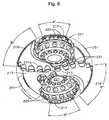
- Each stabilizer pad 51, 151, 251(and the portions of each bit leg 17, 217, 317 and fixed blade 19, 219, 319 that extend radially outwardly to the full gage diameter of the bit 11) describes a segment or angular portion (A, B, C, D, E, and F, in Figure 2 ; A', B', C', and D' in Figure 4 ; and A", B", C", and D" in Figure 6 ) of the circumference of the borehole being drilled (shown in phantom in Figures 2 and 4 ).
- the size (and number) of padspreferably is selected so that the total segment or angular portion of the bit gage circumference equals or exceeds 180 degrees.
- the inventionhas several advantages and includes providing a hybrid drill bit that is stable in drilling operation while avoiding off-center running.
- a stable-running bitavoids damage to cutting elements that could cause premature failure of the bit.
Landscapes
- Engineering & Computer Science (AREA)
- Geology (AREA)
- Life Sciences & Earth Sciences (AREA)
- Mining & Mineral Resources (AREA)
- Physics & Mathematics (AREA)
- Environmental & Geological Engineering (AREA)
- Fluid Mechanics (AREA)
- Mechanical Engineering (AREA)
- General Life Sciences & Earth Sciences (AREA)
- Geochemistry & Mineralogy (AREA)
- Earth Drilling (AREA)
- Processing Of Stones Or Stones Resemblance Materials (AREA)
- Drilling Tools (AREA)
Description
- The present invention relates in general to earth-boring drill bits and, in particular, to a bit having a combination of rolling and fixed cutters and cutting elements as set forth in the independent claims.
- The success of rotary drilling enabled the discovery of deep oil and gas reservoirs and production of enormous quantities of oil. The rotary rock bit was an important invention that made the success of rotary drilling possible. Only soft earthen formations could be penetrated commercially with the earlier drag bit and cable tool, but the two-cone rock bit, invented by Howard R. Hughes,
U.S. Pat. No. 930,759 , drilled the caprock at the Spindletop field, near Beaumont, Tex. with relative ease. That venerable invention, within the first decade of the last century, could drill a scant fraction of the depth and speed of the modern rotary rock bit. The original Hughes bit drilled for hours, the modern bit drills for days. Modem bits sometimes drill for thousands of feet instead of merely a few feet. Many advances have contributed to the impressive improvements in rotary rock bits. - In drilling boreholes in earthen formations using rolling-cone or rolling-cutter bits, rock bits having one, two, or three rolling cutters rotatably mounted thereon are employed. The bit is secured to the lower end of a drillstring that is rotated from the surface or by a downhole motor or turbine. The cutters mounted on the bit roll and slide upon the bottom of the borehole as the drillstring is rotated, thereby engaging and disintegrating the formation material to be removed. The rolling cutters are provided with cutting elements or teeth that are forced to penetrate and gouge the bottom of the borehole by weight from the drillstring. The cuttings from the bottom and sides of the borehole are washed away by drilling fluid that is pumped down from the surface through the hollow, rotating drillstring, and are carried in suspension in the drilling fluid to the surface.
- Rolling cutter bits dominated petroleum drilling for the greater part of the 20th century. With improvements in synthetic diamond technology that occurred in the 1970s and 1980s, the fixed-cutter, or "drag" bit, became popular again in the latter part of the 20th century. Modern fixed-cutter bits are often referred to as "diamond" or "PDC" (polycrystalline diamond compact) bits and are far removed from the original fixed-cutter bits of the 19th and early 20th centuries. Diamond or PDC bits carry cutting elements comprising polycrystalline diamond compact layers or "tables" formed on and bonded to a supporting substrate, conventionally of cemented tungsten carbide, the cutting elements being arranged in selected locations on blades or other structures on the bit body with the diamond tables facing generally in the direction of bit rotation. Diamond bits have an advantage over rolling-cutter bits in that they generally have no moving parts. The drilling mechanics and dynamics of diamond bits are different from those of rolling-cutter bits precisely because they have no moving parts. During drilling operation, diamond bits are used in a manner similar to that for rolling cutter bits, the diamond bits also being rotated against a formation being drilled under applied weight on bit to remove formation material. Engagement between the diamond cutting elements and the borehole bottom and sides shears or scrapes material from the formation, instead of using a crushing action as is employed by rolling-cutter bits. Rolling-cutter and diamond bits each have particular applications for which they are more suitable than the other; neither type of bit is likely to completely supplant the other in the foreseeable future.
- Some earth-boring bits use a combination of one or more rolling cutters and one or more fixed blades. Some of these combination-type drill bits are referred to as hybrid bits. Previous designs of hybrid bits, such as is described in
U.S. Patent No. 4,343,371 toBaker, III, have provided for the rolling cutters to do most of the formation cutting, especially in the center of the hole or bit. Other types of combination bits are known as "core bits," such asU.S. Patent No. 4,006,788 toGarner. Core bits typically have truncated rolling cutters that do not extend to the center of the bit and are designed to remove a core sample of formation by drilling down, but around, a solid cylinder of the formation to be removed from the borehole generally intact. - Another type of hybrid bit is described in
U.S. Patent No. 5,695,019 toShamburger, Jr., wherein the rolling cutters extend almost entirely to the center. Fixed cutter inserts 50 (Figures 2 and3 ) are located in the dome area or "crotch" of the bit to complete the removal of the drilled formation. Still another type of hybrid bit is sometimes referred to as a "hole opener," an example of which is described inU.S. Patent No. 6,527,066 . A hole opener has a fixed threaded protuberance that extends axially beyond the rolling cutters for the attachment of a pilot bit that can be a rolling cutter or fixed cutter bit. In these latter two cases the center is cut with fixed cutter elements but the fixed cutter elements do not form a continuous, uninterrupted cutting profile from the center to the perimeter of the bit. - A concern with all bits is stable running. Fixed- and rolling-cutter bits have different dynamic behavior during drilling operation and therefore different bit characteristics contribute to stable or unstable running. In a stable configuration, a bit drills generally about its geometric center, which corresponds with the axial center of the borehole, and lateral or other dynamic loadings of the bit and its cutting elements are avoided. Stabilizer pads can be provided to increase the area of contact between the bit body and the sidewall of the borehole to contribute to stable running. Such stabilizer pads tend to be effective in fixed-cutter bits, but can actually contribute to unstable running in rolling-cutter bits because the contact point between the pad and the sidewall of the borehole becomes an instant center of rotation of the bit, causing the bit to run off-center. Commonly assigned
U.S. Patent Nos. 4,953,641 to Pessier et al. and5,996,731 to Pessier et al. disclose stabilizer pad arrangements for rolling-cutter bits that avoid the disadvantages of stabilizer pads. None of the foregoing "hybrid" bit disclosures address issues of stable running. - Earth boring bits comprising a combination of rolling and fixed cutters are also known from
JP 2001 159289 A US 2,297,157 A which furthermore discloses astabiliser 25 extending radially adjacent the fixed cutter 20 opposite thereaming cutter 17. Further, the provision of stabilizers in conjunction with roller cutters is known fromUS 2002/0092684 A1 andUS 6,116,357 A . - Although each of these bits is workable for certain limited applications, an improved hybrid earth-boring bit with enhanced stabilization to improve drilling performance would be desirable.
- Embodiments of the present invention comprise an improved earth-boring bit of the hybrid variety. One embodiment comprises a bit body configured at its upper extent for connection into a drillstring. At least one fixed blade extends downwardly from the bit body, and has a radially outermost gage surface. A plurality of fixed cutting elements is secured to the fixed blade, preferably in a row at its rotationally leading edge and the radially outermost cutting elements on the radially outermost surface of the fixed blade define the bit and borehole diameter. At least one bit leg is secured to the bit body and a rolling cutter is mounted for rotation on the bit leg. At least one stabilizer pad is disposed between the bit leg and the fixed blade, the stabilizer pad extending radially outward to substantially the gage surface.
- According to an embodiment of the present invention, the stabilizer pad is formed integrally with the fixed blade and extends toward the bit leg in a rotationally leading direction
- According to an embodiment of the present invention, a portion of the bit leg extends radially outward to substantially the gage surface and the stabilizer pad, the gage surface of each fixed blade, and the portion of the bit leg extending to the gage surface together describe a segment of the circumference of the borehole that equals or exceeds 180 degrees.
- According to an embodiment of the present invention, each stabilizer pad has an equal area.
- According to an embodiment of the present invention, there may be a plurality of fixed blades and bit legs and associated rolling cutters.
- According to an embodiment of the present invention, the outermost radial surfaces of the bit legs and fixed blades are joined or formed integrally to define a stabilizer pad.
- Other features and advantages of embodiments of the earth-boring bit according to the present invention will become apparent with reference to the drawings and the detailed description of the invention.
- So that the manner in which the features and advantages of the present invention, which will become apparent, are attained and can be understood in more detail, more particular description of embodiments of the invention as briefly summarized above may be had by reference to the embodiments thereof that are illustrated in the appended drawings which form a part of this specification. It is to be noted, however, that the drawings illustrate only some embodiments of the invention and therefore are not to be considered limiting of its scope as the invention may admit to other equally effective embodiments.
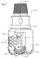
Figure 1 is a side elevation view of an embodiment of the hybrid earth-boring bit constructed in accordance with the present invention;Figure 2 is a bottom plan view of the embodiment of the hybrid earth-boring bit ofFigure 1 constructed in accordance with the present invention;Figure 3 is a side elevation view of an embodiment of the hybrid earth-boring bit constructed in accordance with the present invention;Figure 4 is a bottom plan view of the embodiment of the hybrid earth-boring bit ofFigure3 constructed in accordance with the present invention;Figure 5 is a side elevation view of an embodiment of the hybrid earth-boring bit constructed in accordance with the present invention;Figure 6 is a bottom plan view of the embodiment of the hybrid earth-boring bit ofFigure 5 constructed in accordance with the present invention;Figure 7 is a side elevation view of another embodiment of the hybrid earth-boring bit constructed in accordance with the present invention; andFigure 8 is a bottom plan view of the embodiment of the hybrid earth-boring bit ofFigure 7 constructed in accordance with the present invention.- Referring to
Figures 1 through 8 , and particularly toFigures 1 and2 , an earth-boringbit 11 according to an illustrative embodiment of the present invention is disclosed.Bit 11 comprises abit body 13 having a centrallongitudinal axis 15 that defines an axial center of thebit body 13. In the illustrated embodiment, thebit body 13 is steel, but could also be formed of matrix material with steel reinforcements, or of a sintered carbide material.Bit body 13 includes a shank at the upper or trailing end thereof threaded or otherwise configured for attachment to a hollow drillstring (not shown), which rotatesbit 11 and provides pressurized drilling fluid to the bit and the formation being drilled. - At least one (two are shown)
bit leg 17 extends downwardly from thebit body 13 in the axial direction. Thebit body 13 also has a plurality (e.g., also two shown) of fixedblades 19 that extend downwardly in the axial direction. The number ofbit legs 17 and fixedblades 19 is at least one but may be more than two. In the illustrated embodiment, bit legs 17 (and the associated rolling cutters) are not directly opposite one another (are about 191 degrees apart measured in the direction of rotation of bit 11), nor are fixed blades 19 (which are about 169 degrees apart measured in the direction of rotation of bit 11). Other spacings and distributions oflegs 17 andblades 19 may be appropriate. - A rolling
cutter 21 is mounted on a sealed journal bearing that is part of eachbit leg 17. According to the illustrated embodiment, the rotational axis of each rollingcutter 21 intersects theaxial center 15 of the bit. Unsealed journal or sealed or unsealed rolling-element bearings may be employed in addition to the sealed journal bearing. The radially outermost surface of each rolling cutter 21 (typically called the gage cutter surface in conventional rolling cutter bits), is spaced slightly radially inward from the outermost gage surface ofbit body 13, but the radially outermost surfaces of the bit legs may extend to full gage diameter (typically within 0.127-0.635 cm (0.050-0.250 inch) of full gage diameter), so that the bit legs contact the sidewall of the borehole during drilling operation to assist in stabilizing the bit during drilling operation. The radially outermost surface of eachbit leg 17 may also be recessed from the full gage diameter, in which case less or no stabilization is effected. In the illustrated embodiment, rollingcutters 21 have no skew or angle and no offset, so that the axis of rotation of each rollingcutter 21 intersects the axial center (central axis) 15 of thebit body 13. Alternatively, the rollingcutters 21 may be provided with skew angle and (or) offset to induce sliding of the rollingcutters 21 as they roll over the borehole bottom. - At least one (a plurality is illustrated) rolling-
cutter cutting elements 25 are arranged on the rollingcutters 21 in generally circumferential rows. Rolling-cutter cutting elements 25 need not be arranged in rows, but instead could be "randomly" placed on each rollingcutter 21. Moreover, the rolling-cutter cutting elements may take the form of one or more discs or "kerf-rings," which would also fall within the meaning of the term rolling-cutter cutting elements. - Tungsten carbide inserts 25, secured by interference fit into bores in the rolling
cutter 21 are shown, but a milled- or steel-tooth cutter having hardfaced cutting elements (25) integrally formed with and protruding from the rolling cutter could be used in certain applications and the term "rolling-cutter cutting elements" as used herein encompasses such teeth. The inserts or cutting elements may be chisel- shaped as shown, conical, round, or ovoid, or other shapes and combinations of shapes depending upon the application. Rolling-cutter cutting elements 25 may also be formed of, or coated with, super-abrasive or super-hard materials such as polycrystalline diamond, cubic boron nitride, and the like. - In addition, a plurality of fixed-
blade cutting elements 31 are arranged in a row and secured to each of the fixedblades 19 at the rotationally leading edges thereof (leading being defined in the direction of rotation of bit 11). Each of the fixed-blade cutting elements 31 comprises a polycrystalline diamond layer or table on a rotationally leading face of a supporting tungsten carbide substrate, the diamond layer or table providing a cutting face having a cutting edge at a periphery thereof for engaging the formation. The radiallyoutermost cutting elements 31 on the radially outermost surface of each of the fixedblades 19 define the bit and borehole diameter (shown in phantom inFigures 2 ,4 and6 ) drilled bybit 11. Each blade may also be provided with back-upcutters 33. - In addition to fixed-blade cutting elements 31 (and backup cutters 33) including polycrystalline diamond tables mounted on tungsten carbide substrates, such term as used herein encompasses thermally stable polycrystalline diamond (TSP) wafers or tables mounted on tungsten carbide substrates, and other, similar super-abrasive or super-hard materials such as cubic boron nitride and diamond-like carbon. Fixed-
blade cutting elements 31 may be brazed or otherwise secured in recesses or "pockets" on eachblade 19 so that their peripheral or cutting edges on cutting faces are presented to the formation. - The upper, radially outermost (gage) surface of each fixed
blade 19 extends to full gage diameter (typically within 0.127-0.635 cm (0.050-0.250 inch) of full gage diameter) and serves as a stabilizer. This surface may be provided with a plurality of flat-toppedinserts 41 that may or may not be configured with relatively sharp cutting edges. Without sharp cutting edges, inserts 41 serve to resist wear of the upper portion of each fixed blade. With sharp cutting edges, as disclosed in commonly assignedU.S. Patent Nos. 5,287,936 ,5,346,026 ,5,467,836 ,5,655,612 , and6,050,354 , inserts 41 assist with reaming and maintaining the gage diameter of the borehole.Inserts 41 may be formed of tungsten carbide or other hard metal, alone or in combination with polycrystalline or synthetic or natural diamond or other super-abrasive material. Super-abrasive materials are preferred, but not necessary, ifinserts 41 are provided with sharp cutting edges for active cutting of the sidewall of the borehole. Inserts may be brazed or interference fit, or otherwise conventionally secured to fixed blades 19 (and may also be provided on the radially outermost surfaces of bit legs 17). - According to the illustrated embodiment, at least a portion of at least one of the fixed
cutting elements 31 is located near or at theaxial center 15 of thebit body 13 and thus is positioned to remove formation material at the axial center of the borehole (typically, the axial center of the bit will generally coincide with the center of the borehole being drilled, with some minimal variation due to lateral bit movement during drilling). In a 20 cm (7-7/8 inch) bit as illustrated, at least one of the fixedcutting elements 31 has its laterally innermost edge tangent or in close proximity to theaxial center 15 of thebit 11. While this center-cutting feature is a preferred embodiment, the teachings of the present invention are equally applicable to hybrid bits lacking this feature. - A
stabilizer pad bit body 13 between eachbit leg 17 and fixedblade 19, preferably rotationally leading or ahead of each fixedblade 19 and midway betweenblade 19 and bitleg 17. Each stabilizer pad extends radially outwardly to the full gage diameter (again, typically within 0.127-0.635 cm (0.050-0.250 inch)) ofbit 11 to ensure that eachpad Figures 1 and2 ,stabilizer pads 51 are discrete and separate from fixedblade 19 and bitleg 17. Alternatively, as shown inFigures 3 and4 ,stabilizer pads 151 are integral with and extend in a rotationally leading direction from each fixedblade 19. The term "integral" is intended to encompass any manufacturing process resulting in the structure shown inFigures 3 and4 . The pads could also be multiple discrete pads betweenbit legs 17 andblades 19. - Each
pad U.S. Patent No. 5,996,713 to Pessier, et al. Additionally, the area (exposed to the sidewall of the borehole being drilled) of eachpad bit 11. Figures 5 and6 illustrate another embodiment of the invention that is generally similar to the embodiments ofFigures 1 through4 (similar structures are numbered similarly, e.g., bitlegs blades blade 219 is made wider than typical and, rather than extending axially downward and parallel to thelongitudinal axis 215, extends helically or spirally or linearly at an angle relative to (not or non-parallel to) thelongitudinal axis 215, i.e., at an angle other than zero. Both the leading 219A and trailingedges 219B of the gage surface of eachblade 219 extend downwardly at a selected angle (approximately 20 degrees is illustrated inFigure 5 ). Alternatively, one of the leading or trailingedges - As shown in
Figure 6 , each blade then operates as a stabilizer pad that describes a much larger segment or angular portion (labeled B" and D") than a "straight" blade that extends downward parallel to thelongitudinal axis 215 ofbit 211. Such a configuration is especially useful when there are relativelyfew blades 219 and provides stabilization in the area rotationally trailing eachblade 219, which can be useful for preventing backward whirl. Additionally, the spiral or angled blade configuration creates large-area stabilizer pads without blocking or impeding the return flow to the same extent as a discrete stabilizer pad of the same area, allowing freer return of drilling fluid and cuttings through the junk slots to the annulus. Nevertheless, as can be seen inFigure 6 , the angled orspiral blades 219 leave a significant amount of "chordal drop" present in the region leading eachblade 219. Chordal drop is measured by drawing a chord between the leading edge ofblade 219 and trailing edge of bit leg 217 (it is a chord of the borehole diameter). The maximum distance between the chord and the gage or borehole diameter, measured perpendicular to the chord, is the chordal drop. It is desirable that chordal drop be minimized and also equal between eachbit leg 217 andblade 219. In the case of the spiral or angled blade embodiment, it may be desirable to provide a leading stabilization pad 251 (shown in phantom inFigure 6 ) between eachblade 219 andbit leg 217 to avoid excessive chordal drop. Such a stabilization pad preferably is separate from theblade 219, but may also be formed integrally, as described above in connection withFigures 3 and4 . Figures 7 and8 disclose another illustrative embodiment in which stabilization is achieved by merging the radially outermost portions of each bit leg (317) with the fixed blade that rotationally leads the leg (similar structures numbered similarly, e.g. bitlegs blades bit legs 317 and fixedblades 319 are congruent at the gage diameter of the bit and are circumferentially joined or integrally formed so that there is no junk slot formed between theblade 319 and thebit leg 317 that rotationally trails it. This merged structure forms a stabilizer pad (not numbered). Although the terms "joined" or "merged" are used, they are intended to encompass any manufacturing process resulting in a single radially outermost surface for eachblade 319 and theleg 317 that trails it, whether the process involves actually joining the structures or forming them integrally as a single unit. The illustrative embodiment shows two legs 317 (and associatedcutters 321, 323) and twoblades 319, but bits having more blades and more legs (and associated cutters). However, this embodiment is not as easily adapted to bits having uneven numbers of blades and bit legs (and associated cutters) as are the embodimentsofFigures 1 through6 .- Each
stabilizer pad bit leg blade Figure 2 ; A', B', C', and D' inFigure 4 ; and A", B", C", and D" inFigure 6 ) of the circumference of the borehole being drilled (shown in phantom inFigures 2 and4 ). The size (and number) of pads preferably is selected so that the total segment or angular portion of the bit gage circumference equals or exceeds 180 degrees. This includes the segment or angular portion described by the gage or radially outermost portion of fixedblades 19, and bybit legs 17, if their gage or radially outermost portion extends to full gage diameter, but does not if these structures do not extend to full gage to act as stabilizer pads. - By way of example, the segments or angular portions described by
various stabilizer pads 51, full-gage bit legs 17, and full-gage blades 19 inFigure 2 are:


gage bit legs 17 andblades 19 withintegrated stabilizer pads 151 inFigure 4 are:

- The segments or angular portions described by full-
gage bit legs 217 andblades 219 inFigure 6 are:

- In the case of the embodiment of
Figures 7 and8 , where the stabilizer pad is formed by the joined or integrally formed fixedblades 319 and bitlegs 317, the segments or angular portions described are:
- The invention has several advantages and includes providing a hybrid drill bit that is stable in drilling operation while avoiding off-center running. A stable-running bit avoids damage to cutting elements that could cause premature failure of the bit.
- While the invention has been shown or described in only some of its forms, it should be apparent to those skilled in the art that it is not so limited, but is susceptible to various changes without departing from the scope of the invention as hereinafter claimed.


Claims (12)
- An earth-boring bit (11, 211) comprising:a bit body (13, 213) configured at its upper extent for connection into a drillstring;at least one fixed blade (19, 219) extending downwardly from the bit body (13, 213), the fixed blade (19, 219) having a radially outermost gage surface;a plurality of fixed cutting elements (31, 231) secured to the fixed blade (19, 219);at least one bit leg (17, 217) secured to the bit body (13, 213);characterised bya rolling cutter (21, 221) mounted for rotation on the bit leg (17, 217);at least one stabilizer pad (51, 151, 251) disposed between the at least one bit leg (17, 217) and the at least one fixed blade (19, 219), the stabilizer pad (51, 151) extending radially outward to substantially the gage surface.
- The earth-boring bit (11, 211) according to claim 1, further comprising a plurality of rolling-cutter cutting elements arranged on the rolling cutter (21, 221).
- The earth-boring bit (11, 211) according to claim 1, wherein the stabilizer pad (51, 151, 251) is formed integrally with the fixed blade (19, 219) and extends toward the bit leg (17,217).
- The earth-boring bit (11, 211) according to claim 1, wherein at least a portion of the fixed cutting elements (31, 231) are arranged in a row on a rotationally leading edge of the fixed blade (19, 219).
- The earth-boring bit (11, 211) according to claim 1, wherein the stabilizer pad (51, 151, 251), gage surface of each fixed blade (19, 219), and a portion of the bit leg (17, 217) extending to the gage surface together describe a segment of the circumference of the borehole that equals or exceeds 180 degrees.
- The earth-boring bit (11, 211) according to claim 1, further comprising:a plurality of fixed blades (19, 219) extending downwardly from the bit body (13, 213);a plurality of bit legs (17, 217) extending downwardly from the bit body (13, 213); anda stabilizer pad (51, 151, 251) between each bit leg (17, 217) and each fixed blade (19, 219).
- The earth-boring bit (11, 211) according to claim 1, wherein each stabilizer pad (51, 151, 251) has an equal area exposed to the sidewall of the borehole being drilled.
- An earth-boring bit (311) comprising:a bit body (313) configured at its upper extent for connection into a drillstring;at least one fixed blade (319) extending downwardly from the bit body (313), the fixed blade (319) having a radially outermost gage surface;a plurality of fixed cutting elements (331) secured to each fixed blade (319);at least one bit leg (317) secured to the bit body (313);a rolling cutter (321) mounted for rotation on the bit leg (317) and at least one rolling-cutter cutting element arranged on the rolling cutter (321),characterised by the bit leg (317) having a radially outermost surface, the radially outermost surface of the bit leg (317) extending toward and joining the radially outermost surface of the fixed blade (319);
- The earth-boring bit (311) according to claim 8, further comprising a plurality of rolling-cutter cutting elements arranged on the rolling cutter (321).
- The earth-boring bit (311) according to claim 8, further comprising a plurality of fixed blades (319) and a plurality of bit legs (317), the number of fixed blades (319) being equal to the number of bit legs (317).
- The earth-boring bit (311) according to claim 8, wherein at least a portion of the fixed cutting elements (331) are arranged in a row on a rotationally leading edge of the fixed blade (319).
- The earth-boring bit (311) according to claim 8, wherein the joined radially outermost surfaces of the fixed blade (319) and bit leg (317) together describe a segment of the circumference of the borehole that equals or exceeds 180 degrees.
Applications Claiming Priority (2)
| Application Number | Priority Date | Filing Date | Title |
|---|---|---|---|
| US12/465,377US8459378B2 (en) | 2009-05-13 | 2009-05-13 | Hybrid drill bit |
| PCT/US2010/033513WO2010132232A2 (en) | 2009-05-13 | 2010-05-04 | Hybrid drill bit |
Publications (3)
| Publication Number | Publication Date |
|---|---|
| EP2430278A2 EP2430278A2 (en) | 2012-03-21 |
| EP2430278A4 EP2430278A4 (en) | 2015-04-22 |
| EP2430278B1true EP2430278B1 (en) | 2016-11-09 |
Family
ID=43067608
Family Applications (1)
| Application Number | Title | Priority Date | Filing Date |
|---|---|---|---|
| EP10775268.5ANot-in-forceEP2430278B1 (en) | 2009-05-13 | 2010-05-04 | Hybrid drill bit |
Country Status (6)
| Country | Link |
|---|---|
| US (2) | US8459378B2 (en) |
| EP (1) | EP2430278B1 (en) |
| PL (1) | PL2430278T3 (en) |
| RU (1) | RU2564320C2 (en) |
| SA (1) | SA110310370B1 (en) |
| WO (1) | WO2010132232A2 (en) |
Cited By (1)
| Publication number | Priority date | Publication date | Assignee | Title |
|---|---|---|---|---|
| CN110792397A (en)* | 2019-12-11 | 2020-02-14 | 西南石油大学 | a composite drill |
Families Citing this family (28)
| Publication number | Priority date | Publication date | Assignee | Title |
|---|---|---|---|---|
| US8678111B2 (en) | 2007-11-16 | 2014-03-25 | Baker Hughes Incorporated | Hybrid drill bit and design method |
| US20120205160A1 (en) | 2011-02-11 | 2012-08-16 | Baker Hughes Incorporated | System and method for leg retention on hybrid bits |
| US20090272582A1 (en)* | 2008-05-02 | 2009-11-05 | Baker Hughes Incorporated | Modular hybrid drill bit |
| US8141664B2 (en)* | 2009-03-03 | 2012-03-27 | Baker Hughes Incorporated | Hybrid drill bit with high bearing pin angles |
| US8459378B2 (en) | 2009-05-13 | 2013-06-11 | Baker Hughes Incorporated | Hybrid drill bit |
| US8157026B2 (en) | 2009-06-18 | 2012-04-17 | Baker Hughes Incorporated | Hybrid bit with variable exposure |
| CA2773897A1 (en) | 2009-09-16 | 2011-03-24 | Baker Hughes Incorporated | External, divorced pdc bearing assemblies for hybrid drill bits |
| US8347989B2 (en) | 2009-10-06 | 2013-01-08 | Baker Hughes Incorporated | Hole opener with hybrid reaming section and method of making |
| US8448724B2 (en)* | 2009-10-06 | 2013-05-28 | Baker Hughes Incorporated | Hole opener with hybrid reaming section |
| CN103080458B (en) | 2010-06-29 | 2016-01-20 | 贝克休斯公司 | Drill bit with anti-drill bit recycling groove structure |
| US8978786B2 (en) | 2010-11-04 | 2015-03-17 | Baker Hughes Incorporated | System and method for adjusting roller cone profile on hybrid bit |
| US9782857B2 (en) | 2011-02-11 | 2017-10-10 | Baker Hughes Incorporated | Hybrid drill bit having increased service life |
| WO2013074788A1 (en) | 2011-11-15 | 2013-05-23 | Baker Hughes Incorporated | Hybrid drill bits having increased drilling efficiency |
| US8881848B2 (en) | 2012-05-07 | 2014-11-11 | Ulterra Drilling Technologies, L.P. | Fixed cutter drill bit with rotating cutter disc |
| CN102678055B (en)* | 2012-05-18 | 2015-10-28 | 西南石油大学 | One scrape cut-impact combined drill |
| US9376866B2 (en)* | 2013-08-23 | 2016-06-28 | Varel International Ind., L.P. | Hybrid rotary cone drill bit |
| RU2689465C2 (en) | 2014-05-23 | 2019-05-28 | Бейкер Хьюз Инкорпорейтед | Combined drill bit with mechanical fastening of rock drilling unit elements |
| CN110130833A (en) | 2014-06-18 | 2019-08-16 | 哈利伯顿能源服务公司 | Boring method |
| US11428050B2 (en) | 2014-10-20 | 2022-08-30 | Baker Hughes Holdings Llc | Reverse circulation hybrid bit |
| CN107709693A (en) | 2015-07-17 | 2018-02-16 | 哈里伯顿能源服务公司 | Center has the Mixed drilling bit for reversely rotating cutter |
| GB2564811A (en) | 2016-06-17 | 2019-01-23 | Halliburton Energy Services Inc | Rolling element with half lock |
| GB2567399B (en) | 2016-10-05 | 2021-06-30 | Halliburton Energy Services Inc | Rolling element assembly with a compliant retainer |
| US10907414B2 (en) | 2017-11-09 | 2021-02-02 | Baker Hughes, A Ge Company, Llc | Earth boring tools having fixed blades and varying sized rotatable cutting structures and related methods |
| US10704336B2 (en)* | 2017-11-21 | 2020-07-07 | Baker Hughes, A Ge Company, Llc | Earth boring tools having fixed blades, rotatable cutting structures, and stabilizing structures and related methods |
| CN110685606B (en)* | 2018-07-05 | 2021-11-26 | 成都海锐能源科技有限公司 | Fixed cutting structure-roller composite drill bit |
| RU190616U1 (en)* | 2019-04-23 | 2019-07-04 | Общество с ограниченной ответственностью Научно-производственное предприятие "БУРИНТЕХ" (ООО НПП "БУРИНТЕХ") | HYBRID DRILLING BIT |
| US12084919B2 (en) | 2019-05-21 | 2024-09-10 | Schlumberger Technology Corporation | Hybrid bit |
| CN116601371A (en) | 2020-09-29 | 2023-08-15 | 斯伦贝谢技术有限公司 | Hybrid drill bit |
Family Cites Families (263)
| Publication number | Priority date | Publication date | Assignee | Title |
|---|---|---|---|---|
| USRE23416E (en)* | 1951-10-16 | Drill | ||
| US3126067A (en)* | 1964-03-24 | Roller bit with inserts | ||
| US3126066A (en)* | 1964-03-24 | Rotary drill bit with wiper blade | ||
| US930759A (en)* | 1908-11-20 | 1909-08-10 | Howard R Hughes | Drill. |
| US1388424A (en)* | 1919-06-27 | 1921-08-23 | Edward A George | Rotary bit |
| US1394769A (en)* | 1920-05-18 | 1921-10-25 | C E Reed | Drill-head for oil-wells |
| US1519641A (en)* | 1920-10-12 | 1924-12-16 | Walter N Thompson | Rotary underreamer |
| US1537550A (en) | 1923-01-13 | 1925-05-12 | Reed Roller Bit Co | Lubricator for deep-well-drilling apparatus |
| US1821474A (en)* | 1927-12-05 | 1931-09-01 | Sullivan Machinery Co | Boring tool |
| US1896243A (en)* | 1928-04-12 | 1933-02-07 | Hughes Tool Co | Cutter support for well drills |
| US1816568A (en)* | 1929-06-05 | 1931-07-28 | Reed Roller Bit Co | Drill bit |
| US1874066A (en)* | 1930-04-28 | 1932-08-30 | Floyd L Scott | Combination rolling and scraping cutter drill |
| US1932487A (en)* | 1930-07-11 | 1933-10-31 | Hughes Tool Co | Combination scraping and rolling cutter drill |
| US1879127A (en)* | 1930-07-21 | 1932-09-27 | Hughes Tool Co | Combination rolling and scraping cutter bit |
| US2030722A (en)* | 1933-12-01 | 1936-02-11 | Hughes Tool Co | Cutter assembly |
| US2117481A (en)* | 1935-02-19 | 1938-05-17 | Globe Oil Tools Co | Rock core drill head |
| US2119618A (en)* | 1937-08-28 | 1938-06-07 | John A Zublin | Oversize hole drilling mechanism |
| US2198849A (en)* | 1938-06-09 | 1940-04-30 | Reuben L Waxler | Drill |
| US2204657A (en) | 1938-07-12 | 1940-06-18 | Brendel Clyde | Roller bit |
| US2216894A (en)* | 1939-10-12 | 1940-10-08 | Reed Roller Bit Co | Rock bit |
| US2244537A (en)* | 1939-12-22 | 1941-06-03 | Archer W Kammerer | Well drilling bit |
| US2320136A (en)* | 1940-09-30 | 1943-05-25 | Archer W Kammerer | Well drilling bit |
| US2297157A (en)* | 1940-11-16 | 1942-09-29 | Mcclinton John | Drill |
| US2318370A (en) | 1940-12-06 | 1943-05-04 | Kasner M | Oil well drilling bit |
| US2320137A (en)* | 1941-08-12 | 1943-05-25 | Archer W Kammerer | Rotary drill bit |
| US2358642A (en) | 1941-11-08 | 1944-09-19 | Archer W Kammerer | Rotary drill bit |
| US2380112A (en)* | 1942-01-02 | 1945-07-10 | Kinnear Clarence Wellington | Drill |
| US2520517A (en) | 1946-10-25 | 1950-08-29 | Manley L Natland | Apparatus for drilling wells |
| US2557302A (en) | 1947-12-12 | 1951-06-19 | Aubrey F Maydew | Combination drag and rotary drilling bit |
| US2575438A (en) | 1949-09-28 | 1951-11-20 | Kennametal Inc | Percussion drill bit body |
| US2628821A (en) | 1950-10-07 | 1953-02-17 | Kennametal Inc | Percussion drill bit body |
| US2719026A (en)* | 1952-04-28 | 1955-09-27 | Reed Roller Bit Co | Earth boring drill |
| US2815932A (en)* | 1956-02-29 | 1957-12-10 | Norman E Wolfram | Retractable rock drill bit apparatus |
| US2994389A (en)* | 1957-06-07 | 1961-08-01 | Le Bus Royalty Company | Combined drilling and reaming apparatus |
| US3066749A (en)* | 1959-08-10 | 1962-12-04 | Jersey Prod Res Co | Combination drill bit |
| US3010708A (en)* | 1960-04-11 | 1961-11-28 | Goodman Mfg Co | Rotary mining head and core breaker therefor |
| US3050293A (en)* | 1960-05-12 | 1962-08-21 | Goodman Mfg Co | Rotary mining head and core breaker therefor |
| US3055443A (en)* | 1960-05-31 | 1962-09-25 | Jersey Prod Res Co | Drill bit |
| SU145867A1 (en)* | 1961-07-08 | 1961-11-30 | И.И. Барабашкин | Roller bit with cutting blades |
| US3239431A (en)* | 1963-02-21 | 1966-03-08 | Knapp Seth Raymond | Rotary well bits |
| US3174564A (en)* | 1963-06-10 | 1965-03-23 | Hughes Tool Co | Combination core bit |
| US3250337A (en)* | 1963-10-29 | 1966-05-10 | Max J Demo | Rotary shock wave drill bit |
| US3269469A (en)* | 1964-01-10 | 1966-08-30 | Hughes Tool Co | Solid head rotary-percussion bit with rolling cutters |
| US3387673A (en)* | 1966-03-15 | 1968-06-11 | Ingersoll Rand Co | Rotary percussion gang drill |
| US3424258A (en)* | 1966-11-16 | 1969-01-28 | Japan Petroleum Dev Corp | Rotary bit for use in rotary drilling |
| DE1301784B (en) | 1968-01-27 | 1969-08-28 | Deutsche Erdoel Ag | Combination bit for plastic rock |
| US3583501A (en)* | 1969-03-06 | 1971-06-08 | Mission Mfg Co | Rock bit with powered gauge cutter |
| USRE28625E (en) | 1970-08-03 | 1975-11-25 | Rock drill with increased bearing life | |
| US3760894A (en) | 1971-11-10 | 1973-09-25 | M Pitifer | Replaceable blade drilling bits |
| US4006788A (en)* | 1975-06-11 | 1977-02-08 | Smith International, Inc. | Diamond cutter rock bit with penetration limiting |
| JPS5382601A (en)* | 1976-12-28 | 1978-07-21 | Tokiwa Kogyo Kk | Rotary grinding type excavation drill head |
| US4140189A (en)* | 1977-06-06 | 1979-02-20 | Smith International, Inc. | Rock bit with diamond reamer to maintain gage |
| US4270812A (en)* | 1977-07-08 | 1981-06-02 | Thomas Robert D | Drill bit bearing |
| US4187922A (en) | 1978-05-12 | 1980-02-12 | Dresser Industries, Inc. | Varied pitch rotary rock bit |
| DE2960568D1 (en) | 1978-05-30 | 1981-11-05 | Grootcon Uk Ltd | Method of welding metal parts |
| US4285409A (en)* | 1979-06-28 | 1981-08-25 | Smith International, Inc. | Two cone bit with extended diamond cutters |
| US4527637A (en)* | 1981-05-11 | 1985-07-09 | Bodine Albert G | Cycloidal drill bit |
| US4293048A (en)* | 1980-01-25 | 1981-10-06 | Smith International, Inc. | Jet dual bit |
| US4343371A (en)* | 1980-04-28 | 1982-08-10 | Smith International, Inc. | Hybrid rock bit |
| US4369849A (en)* | 1980-06-05 | 1983-01-25 | Reed Rock Bit Company | Large diameter oil well drilling bit |
| US4359112A (en)* | 1980-06-19 | 1982-11-16 | Smith International, Inc. | Hybrid diamond insert platform locator and retention method |
| US4320808A (en)* | 1980-06-24 | 1982-03-23 | Garrett Wylie P | Rotary drill bit |
| US4386669A (en)* | 1980-12-08 | 1983-06-07 | Evans Robert F | Drill bit with yielding support and force applying structure for abrasion cutting elements |
| US4428687A (en)* | 1981-05-11 | 1984-01-31 | Hughes Tool Company | Floating seal for earth boring bit |
| US4410284A (en)* | 1982-04-22 | 1983-10-18 | Smith International, Inc. | Composite floating element thrust bearing |
| US4527644A (en) | 1983-03-25 | 1985-07-09 | Allam Farouk M | Drilling bit |
| US4444281A (en)* | 1983-03-30 | 1984-04-24 | Reed Rock Bit Company | Combination drag and roller cutter drill bit |
| EP0162107A1 (en) | 1983-11-18 | 1985-11-27 | Rock Bit Industries U.S.A. Inc. | Hybrid rock bit |
| US4726718A (en)* | 1984-03-26 | 1988-02-23 | Eastman Christensen Co. | Multi-component cutting element using triangular, rectangular and higher order polyhedral-shaped polycrystalline diamond disks |
| AU3946885A (en) | 1984-03-26 | 1985-10-03 | Norton Christensen Inc. | Cutting element using polycrystalline diamond disks |
| US5028177A (en) | 1984-03-26 | 1991-07-02 | Eastman Christensen Company | Multi-component cutting element using triangular, rectangular and higher order polyhedral-shaped polycrystalline diamond disks |
| US4572306A (en)* | 1984-12-07 | 1986-02-25 | Dorosz Dennis D E | Journal bushing drill bit construction |
| US4738322A (en)* | 1984-12-21 | 1988-04-19 | Smith International Inc. | Polycrystalline diamond bearing system for a roller cone rock bit |
| US4657091A (en)* | 1985-05-06 | 1987-04-14 | Robert Higdon | Drill bits with cone retention means |
| SU1331988A1 (en) | 1985-07-12 | 1987-08-23 | И.И. Барабашкин, И. В. Воевидко и В. М. Ивасив | Well calibrator |
| US4664705A (en)* | 1985-07-30 | 1987-05-12 | Sii Megadiamond, Inc. | Infiltrated thermally stable polycrystalline diamond |
| GB8528894D0 (en) | 1985-11-23 | 1986-01-02 | Nl Petroleum Prod | Rotary drill bits |
| US4690228A (en)* | 1986-03-14 | 1987-09-01 | Eastman Christensen Company | Changeover bit for extended life, varied formations and steady wear |
| US4706765A (en)* | 1986-08-11 | 1987-11-17 | Four E Inc. | Drill bit assembly |
| US4943488A (en) | 1986-10-20 | 1990-07-24 | Norton Company | Low pressure bonding of PCD bodies and method for drill bits and the like |
| US5116568A (en) | 1986-10-20 | 1992-05-26 | Norton Company | Method for low pressure bonding of PCD bodies |
| US5030276A (en) | 1986-10-20 | 1991-07-09 | Norton Company | Low pressure bonding of PCD bodies and method |
| US4727942A (en)* | 1986-11-05 | 1988-03-01 | Hughes Tool Company | Compensator for earth boring bits |
| US4765205A (en)* | 1987-06-01 | 1988-08-23 | Bob Higdon | Method of assembling drill bits and product assembled thereby |
| CA1270479A (en)* | 1987-12-14 | 1990-06-19 | Jerome Labrosse | Tubing bit opener |
| USRE37450E1 (en) | 1988-06-27 | 2001-11-20 | The Charles Machine Works, Inc. | Directional multi-blade boring head |
| US5027912A (en) | 1988-07-06 | 1991-07-02 | Baker Hughes Incorporated | Drill bit having improved cutter configuration |
| US4874047A (en)* | 1988-07-21 | 1989-10-17 | Cummins Engine Company, Inc. | Method and apparatus for retaining roller cone of drill bit |
| US4875532A (en)* | 1988-09-19 | 1989-10-24 | Dresser Industries, Inc. | Roller drill bit having radial-thrust pilot bushing incorporating anti-galling material |
| US4892159A (en)* | 1988-11-29 | 1990-01-09 | Exxon Production Research Company | Kerf-cutting apparatus and method for improved drilling rates |
| NO169735C (en) | 1989-01-26 | 1992-07-29 | Geir Tandberg | COMBINATION DRILL KRONE |
| GB8907618D0 (en) | 1989-04-05 | 1989-05-17 | Morrison Pumps Sa | Drilling |
| US4932484A (en)* | 1989-04-10 | 1990-06-12 | Amoco Corporation | Whirl resistant bit |
| US4953641A (en) | 1989-04-27 | 1990-09-04 | Hughes Tool Company | Two cone bit with non-opposite cones |
| US4936398A (en) | 1989-07-07 | 1990-06-26 | Cledisc International B.V. | Rotary drilling device |
| US4976324A (en)* | 1989-09-22 | 1990-12-11 | Baker Hughes Incorporated | Drill bit having diamond film cutting surface |
| US5049164A (en) | 1990-01-05 | 1991-09-17 | Norton Company | Multilayer coated abrasive element for bonding to a backing |
| US4991671A (en) | 1990-03-13 | 1991-02-12 | Camco International Inc. | Means for mounting a roller cutter on a drill bit |
| US4984643A (en) | 1990-03-21 | 1991-01-15 | Hughes Tool Company | Anti-balling earth boring bit |
| US5224560A (en) | 1990-10-30 | 1993-07-06 | Modular Engineering | Modular drill bit |
| US5145017A (en) | 1991-01-07 | 1992-09-08 | Exxon Production Research Company | Kerf-cutting apparatus for increased drilling rates |
| US5941322A (en) | 1991-10-21 | 1999-08-24 | The Charles Machine Works, Inc. | Directional boring head with blade assembly |
| US5238074A (en) | 1992-01-06 | 1993-08-24 | Baker Hughes Incorporated | Mosaic diamond drag bit cutter having a nonuniform wear pattern |
| US5287936A (en) | 1992-01-31 | 1994-02-22 | Baker Hughes Incorporated | Rolling cone bit with shear cutting gage |
| US5467836A (en) | 1992-01-31 | 1995-11-21 | Baker Hughes Incorporated | Fixed cutter bit with shear cutting gage |
| US5346026A (en) | 1992-01-31 | 1994-09-13 | Baker Hughes Incorporated | Rolling cone bit with shear cutting gage |
| NO176528C (en) | 1992-02-17 | 1995-04-19 | Kverneland Klepp As | Device at drill bit |
| EP0569663A1 (en) | 1992-05-15 | 1993-11-18 | Baker Hughes Incorporated | Improved anti-whirl drill bit |
| US5558170A (en) | 1992-12-23 | 1996-09-24 | Baroid Technology, Inc. | Method and apparatus for improving drill bit stability |
| US5289889A (en) | 1993-01-21 | 1994-03-01 | Marvin Gearhart | Roller cone core bit with spiral stabilizers |
| US5361859A (en) | 1993-02-12 | 1994-11-08 | Baker Hughes Incorporated | Expandable gage bit for drilling and method of drilling |
| US5560440A (en) | 1993-02-12 | 1996-10-01 | Baker Hughes Incorporated | Bit for subterranean drilling fabricated from separately-formed major components |
| US5355559A (en) | 1993-04-26 | 1994-10-18 | Amerock Corporation | Hinge for inset doors |
| US5351770A (en)* | 1993-06-15 | 1994-10-04 | Smith International, Inc. | Ultra hard insert cutters for heel row rotary cone rock bit applications |
| US5429200A (en) | 1994-03-31 | 1995-07-04 | Dresser Industries, Inc. | Rotary drill bit with improved cutter |
| US5452771A (en) | 1994-03-31 | 1995-09-26 | Dresser Industries, Inc. | Rotary drill bit with improved cutter and seal protection |
| US5472057A (en) | 1994-04-11 | 1995-12-05 | Atlantic Richfield Company | Drilling with casing and retrievable bit-motor assembly |
| US5606895A (en) | 1994-08-08 | 1997-03-04 | Dresser Industries, Inc. | Method for manufacture and rebuild a rotary drill bit |
| US5439068B1 (en) | 1994-08-08 | 1997-01-14 | Dresser Ind | Modular rotary drill bit |
| US5513715A (en) | 1994-08-31 | 1996-05-07 | Dresser Industries, Inc. | Flat seal for a roller cone rock bit |
| US5547033A (en) | 1994-12-07 | 1996-08-20 | Dresser Industries, Inc. | Rotary cone drill bit and method for enhanced lifting of fluids and cuttings |
| US5553681A (en) | 1994-12-07 | 1996-09-10 | Dresser Industries, Inc. | Rotary cone drill bit with angled ramps |
| US5755297A (en) | 1994-12-07 | 1998-05-26 | Dresser Industries, Inc. | Rotary cone drill bit with integral stabilizers |
| US5593231A (en) | 1995-01-17 | 1997-01-14 | Dresser Industries, Inc. | Hydrodynamic bearing |
| US5996713A (en) | 1995-01-26 | 1999-12-07 | Baker Hughes Incorporated | Rolling cutter bit with improved rotational stabilization |
| US5570750A (en) | 1995-04-20 | 1996-11-05 | Dresser Industries, Inc. | Rotary drill bit with improved shirttail and seal protection |
| US5641029A (en) | 1995-06-06 | 1997-06-24 | Dresser Industries, Inc. | Rotary cone drill bit modular arm |
| US5695019A (en)* | 1995-08-23 | 1997-12-09 | Dresser Industries, Inc. | Rotary cone drill bit with truncated rolling cone cutters and dome area cutter inserts |
| USD384084S (en) | 1995-09-12 | 1997-09-23 | Dresser Industries, Inc. | Rotary cone drill bit |
| US5695018A (en) | 1995-09-13 | 1997-12-09 | Baker Hughes Incorporated | Earth-boring bit with negative offset and inverted gage cutting elements |
| US5904213A (en) | 1995-10-10 | 1999-05-18 | Camco International (Uk) Limited | Rotary drill bits |
| US5862871A (en) | 1996-02-20 | 1999-01-26 | Ccore Technology & Licensing Limited, A Texas Limited Partnership | Axial-vortex jet drilling system and method |
| CA2219985C (en) | 1996-03-01 | 2005-04-19 | Allen Kent Rives | Cantilevered hole opener |
| US5642942A (en) | 1996-03-26 | 1997-07-01 | Smith International, Inc. | Thrust plugs for rotary cone air bits |
| US6390210B1 (en) | 1996-04-10 | 2002-05-21 | Smith International, Inc. | Rolling cone bit with gage and off-gage cutter elements positioned to separate sidewall and bottom hole cutting duty |
| US6241034B1 (en)* | 1996-06-21 | 2001-06-05 | Smith International, Inc. | Cutter element with expanded crest geometry |
| US6116357A (en) | 1996-09-09 | 2000-09-12 | Smith International, Inc. | Rock drill bit with back-reaming protection |
| US5904212A (en) | 1996-11-12 | 1999-05-18 | Dresser Industries, Inc. | Gauge face inlay for bit hardfacing |
| BE1010802A3 (en) | 1996-12-16 | 1999-02-02 | Dresser Ind | Drilling head. |
| BE1010801A3 (en) | 1996-12-16 | 1999-02-02 | Dresser Ind | Drilling tool and / or core. |
| GB9708428D0 (en) | 1997-04-26 | 1997-06-18 | Camco Int Uk Ltd | Improvements in or relating to rotary drill bits |
| US5944125A (en) | 1997-06-19 | 1999-08-31 | Varel International, Inc. | Rock bit with improved thrust face |
| US6095265A (en) | 1997-08-15 | 2000-08-01 | Smith International, Inc. | Impregnated drill bits with adaptive matrix |
| US6367568B2 (en)* | 1997-09-04 | 2002-04-09 | Smith International, Inc. | Steel tooth cutter element with expanded crest |
| US6321862B1 (en)* | 1997-09-08 | 2001-11-27 | Baker Hughes Incorporated | Rotary drill bits for directional drilling employing tandem gage pad arrangement with cutting elements and up-drill capability |
| US6173797B1 (en) | 1997-09-08 | 2001-01-16 | Baker Hughes Incorporated | Rotary drill bits for directional drilling employing movable cutters and tandem gage pad arrangement with active cutting elements and having up-drill capability |
| WO1999037880A1 (en) | 1998-01-26 | 1999-07-29 | Dresser Industries, Inc. | Rotary cone drill bit with enhanced thrust bearing flange |
| US6260635B1 (en) | 1998-01-26 | 2001-07-17 | Dresser Industries, Inc. | Rotary cone drill bit with enhanced journal bushing |
| US6109375A (en) | 1998-02-23 | 2000-08-29 | Dresser Industries, Inc. | Method and apparatus for fabricating rotary cone drill bits |
| US6568490B1 (en) | 1998-02-23 | 2003-05-27 | Halliburton Energy Services, Inc. | Method and apparatus for fabricating rotary cone drill bits |
| EP1066447B1 (en) | 1998-03-26 | 2004-08-18 | Halliburton Energy Services, Inc. | Rotary cone drill bit with improved bearing system |
| JP2000080878A (en) | 1998-06-30 | 2000-03-21 | Kyoei Kogyo Kk | Drilling head for combined use with hard and soft formations |
| US6206116B1 (en) | 1998-07-13 | 2001-03-27 | Dresser Industries, Inc. | Rotary cone drill bit with machined cutting structure |
| US20040045742A1 (en) | 2001-04-10 | 2004-03-11 | Halliburton Energy Services, Inc. | Force-balanced roller-cone bits, systems, drilling methods, and design methods |
| US6241036B1 (en) | 1998-09-16 | 2001-06-05 | Baker Hughes Incorporated | Reinforced abrasive-impregnated cutting elements, drill bits including same |
| US6345673B1 (en) | 1998-11-20 | 2002-02-12 | Smith International, Inc. | High offset bits with super-abrasive cutters |
| US6401844B1 (en) | 1998-12-03 | 2002-06-11 | Baker Hughes Incorporated | Cutter with complex superabrasive geometry and drill bits so equipped |
| SE516079C2 (en)* | 1998-12-18 | 2001-11-12 | Sandvik Ab | Rotary drill bit |
| US6279671B1 (en) | 1999-03-01 | 2001-08-28 | Amiya K. Panigrahi | Roller cone bit with improved seal gland design |
| BE1012545A3 (en) | 1999-03-09 | 2000-12-05 | Security Dbs | Widener borehole. |
| DE60016368T2 (en) | 1999-05-14 | 2005-12-22 | Rives, Allen Kent, Houston | Expanding drill with replaceable arms and cutting elements in various sizes |
| CA2314114C (en) | 1999-07-19 | 2007-04-10 | Smith International, Inc. | Improved rock drill bit with neck protection |
| US6684967B2 (en) | 1999-08-05 | 2004-02-03 | Smith International, Inc. | Side cutting gage pad improving stabilization and borehole integrity |
| US6460631B2 (en) | 1999-08-26 | 2002-10-08 | Baker Hughes Incorporated | Drill bits with reduced exposure of cutters |
| US6533051B1 (en) | 1999-09-07 | 2003-03-18 | Smith International, Inc. | Roller cone drill bit shale diverter |
| US6386302B1 (en) | 1999-09-09 | 2002-05-14 | Smith International, Inc. | Polycrystaline diamond compact insert reaming tool |
| ZA200005048B (en) | 1999-09-24 | 2002-02-14 | Varel International Inc | Improved rotary cone bit for cutting removal. |
| US6460635B1 (en)* | 1999-10-25 | 2002-10-08 | Kalsi Engineering, Inc. | Load responsive hydrodynamic bearing |
| US6510906B1 (en) | 1999-11-29 | 2003-01-28 | Baker Hughes Incorporated | Impregnated bit with PDC cutters in cone area |
| US6843333B2 (en) | 1999-11-29 | 2005-01-18 | Baker Hughes Incorporated | Impregnated rotary drag bit |
| JP3513698B2 (en) | 1999-12-03 | 2004-03-31 | 飛島建設株式会社 | Drilling head |
| US8082134B2 (en) | 2000-03-13 | 2011-12-20 | Smith International, Inc. | Techniques for modeling/simulating, designing optimizing, and displaying hybrid drill bits |
| US6439326B1 (en) | 2000-04-10 | 2002-08-27 | Smith International, Inc. | Centered-leg roller cone drill bit |
| US6688410B1 (en) | 2000-06-07 | 2004-02-10 | Smith International, Inc. | Hydro-lifter rock bit with PDC inserts |
| US6405811B1 (en) | 2000-09-18 | 2002-06-18 | Baker Hughes Corporation | Solid lubricant for air cooled drill bit and method of drilling |
| US6386300B1 (en) | 2000-09-19 | 2002-05-14 | Curlett Family Limited Partnership | Formation cutting method and system |
| DE60140617D1 (en) | 2000-09-20 | 2010-01-07 | Camco Int Uk Ltd | POLYCRYSTALLINE DIAMOND WITH A SURFACE ENRICHED ON CATALYST MATERIAL |
| US6592985B2 (en) | 2000-09-20 | 2003-07-15 | Camco International (Uk) Limited | Polycrystalline diamond partially depleted of catalyzing material |
| US6408958B1 (en) | 2000-10-23 | 2002-06-25 | Baker Hughes Incorporated | Superabrasive cutting assemblies including cutters of varying orientations and drill bits so equipped |
| GB0102160D0 (en)* | 2001-01-27 | 2001-03-14 | Schlumberger Holdings | Cutting structure for earth boring drill bits |
| CA2371740C (en) | 2001-02-13 | 2006-04-18 | Smith International, Inc. | Back reaming tool |
| US7137460B2 (en) | 2001-02-13 | 2006-11-21 | Smith International, Inc. | Back reaming tool |
| WO2003004825A1 (en)* | 2001-07-06 | 2003-01-16 | Shell Internationale Research Maatschappij B.V. | Well drilling bit |
| US7281592B2 (en)* | 2001-07-23 | 2007-10-16 | Shell Oil Company | Injecting a fluid into a borehole ahead of the bit |
| US6745858B1 (en) | 2001-08-24 | 2004-06-08 | Rock Bit International | Adjustable earth boring device |
| US6601661B2 (en) | 2001-09-17 | 2003-08-05 | Baker Hughes Incorporated | Secondary cutting structure |
| US6742607B2 (en) | 2002-05-28 | 2004-06-01 | Smith International, Inc. | Fixed blade fixed cutter hole opener |
| US6823951B2 (en)* | 2002-07-03 | 2004-11-30 | Smith International, Inc. | Arcuate-shaped inserts for drill bits |
| US6902014B1 (en) | 2002-08-01 | 2005-06-07 | Rock Bit L.P. | Roller cone bi-center bit |
| US6883623B2 (en) | 2002-10-09 | 2005-04-26 | Baker Hughes Incorporated | Earth boring apparatus and method offering improved gage trimmer protection |
| US6913098B2 (en)* | 2002-11-21 | 2005-07-05 | Reedeycalog, L.P. | Sub-reamer for bi-center type tools |
| US7234550B2 (en) | 2003-02-12 | 2007-06-26 | Smith International, Inc. | Bits and cutting structures |
| US20060032677A1 (en) | 2003-02-12 | 2006-02-16 | Smith International, Inc. | Novel bits and cutting structures |
| US20040156676A1 (en)* | 2003-02-12 | 2004-08-12 | Brent Boudreaux | Fastener for variable mounting |
| US6904984B1 (en) | 2003-06-20 | 2005-06-14 | Rock Bit L.P. | Stepped polycrystalline diamond compact insert |
| US7011170B2 (en) | 2003-10-22 | 2006-03-14 | Baker Hughes Incorporated | Increased projection for compacts of a rolling cone drill bit |
| US7395882B2 (en) | 2004-02-19 | 2008-07-08 | Baker Hughes Incorporated | Casing and liner drilling bits |
| US7070011B2 (en) | 2003-11-17 | 2006-07-04 | Baker Hughes Incorporated | Steel body rotary drill bits including support elements affixed to the bit body at least partially defining cutter pocket recesses |
| GB2408735B (en) | 2003-12-05 | 2009-01-28 | Smith International | Thermally-stable polycrystalline diamond materials and compacts |
| US20050178587A1 (en) | 2004-01-23 | 2005-08-18 | Witman George B.Iv | Cutting structure for single roller cone drill bit |
| US7195086B2 (en) | 2004-01-30 | 2007-03-27 | Anna Victorovna Aaron | Anti-tracking earth boring bit with selected varied pitch for overbreak optimization and vibration reduction |
| US7647993B2 (en) | 2004-05-06 | 2010-01-19 | Smith International, Inc. | Thermally stable diamond bonded materials and compacts |
| ITMI20051579A1 (en) | 2004-08-16 | 2006-02-17 | Halliburton Energy Serv Inc | DRILLING TIPS WITH ROTATING CONES WITH OPTIMIZED BEARING STRUCTURES |
| US7754333B2 (en) | 2004-09-21 | 2010-07-13 | Smith International, Inc. | Thermally stable diamond polycrystalline diamond constructions |
| GB0423597D0 (en) | 2004-10-23 | 2004-11-24 | Reedhycalog Uk Ltd | Dual-edge working surfaces for polycrystalline diamond cutting elements |
| US7350601B2 (en) | 2005-01-25 | 2008-04-01 | Smith International, Inc. | Cutting elements formed from ultra hard materials having an enhanced construction |
| US7435478B2 (en) | 2005-01-27 | 2008-10-14 | Smith International, Inc. | Cutting structures |
| CA2535387C (en) | 2005-02-08 | 2013-05-07 | Smith International, Inc. | Thermally stable polycrystalline diamond cutting elements and bits incorporating the same |
| US7350568B2 (en) | 2005-02-09 | 2008-04-01 | Halliburton Energy Services, Inc. | Logging a well |
| US20060196699A1 (en) | 2005-03-04 | 2006-09-07 | Roy Estes | Modular kerfing drill bit |
| US7472764B2 (en) | 2005-03-25 | 2009-01-06 | Baker Hughes Incorporated | Rotary drill bit shank, rotary drill bits so equipped, and methods of manufacture |
| US7487849B2 (en) | 2005-05-16 | 2009-02-10 | Radtke Robert P | Thermally stable diamond brazing |
| US7377341B2 (en) | 2005-05-26 | 2008-05-27 | Smith International, Inc. | Thermally stable ultra-hard material compact construction |
| US7493973B2 (en) | 2005-05-26 | 2009-02-24 | Smith International, Inc. | Polycrystalline diamond materials having improved abrasion resistance, thermal stability and impact resistance |
| US20060278442A1 (en) | 2005-06-13 | 2006-12-14 | Kristensen Henry L | Drill bit |
| US7320375B2 (en) | 2005-07-19 | 2008-01-22 | Smith International, Inc. | Split cone bit |
| US7462003B2 (en) | 2005-08-03 | 2008-12-09 | Smith International, Inc. | Polycrystalline diamond composite constructions comprising thermally stable diamond volume |
| US7416036B2 (en) | 2005-08-12 | 2008-08-26 | Baker Hughes Incorporated | Latchable reaming bit |
| US9574405B2 (en) | 2005-09-21 | 2017-02-21 | Smith International, Inc. | Hybrid disc bit with optimized PDC cutter placement |
| US7726421B2 (en) | 2005-10-12 | 2010-06-01 | Smith International, Inc. | Diamond-bonded bodies and compacts with improved thermal stability and mechanical strength |
| US7152702B1 (en) | 2005-11-04 | 2006-12-26 | Smith International, Inc. | Modular system for a back reamer and method |
| US7802495B2 (en)* | 2005-11-10 | 2010-09-28 | Baker Hughes Incorporated | Methods of forming earth-boring rotary drill bits |
| US7270196B2 (en) | 2005-11-21 | 2007-09-18 | Hall David R | Drill bit assembly |
| US7398837B2 (en) | 2005-11-21 | 2008-07-15 | Hall David R | Drill bit assembly with a logging device |
| US7484576B2 (en)* | 2006-03-23 | 2009-02-03 | Hall David R | Jack element in communication with an electric motor and or generator |
| US7392862B2 (en) | 2006-01-06 | 2008-07-01 | Baker Hughes Incorporated | Seal insert ring for roller cone bits |
| US7628234B2 (en) | 2006-02-09 | 2009-12-08 | Smith International, Inc. | Thermally stable ultra-hard polycrystalline materials and compacts |
| GB2453875C (en)* | 2006-10-02 | 2009-09-16 | Smith International | Drill bits with dropping tendencies |
| US7387177B2 (en) | 2006-10-18 | 2008-06-17 | Baker Hughes Incorporated | Bearing insert sleeve for roller cone bit |
| US8034136B2 (en) | 2006-11-20 | 2011-10-11 | Us Synthetic Corporation | Methods of fabricating superabrasive articles |
| US7845435B2 (en) | 2007-04-05 | 2010-12-07 | Baker Hughes Incorporated | Hybrid drill bit and method of drilling |
| US7841426B2 (en) | 2007-04-05 | 2010-11-30 | Baker Hughes Incorporated | Hybrid drill bit with fixed cutters as the sole cutting elements in the axial center of the drill bit |
| US7703557B2 (en)* | 2007-06-11 | 2010-04-27 | Smith International, Inc. | Fixed cutter bit with backup cutter elements on primary blades |
| US7847437B2 (en)* | 2007-07-30 | 2010-12-07 | Gm Global Technology Operations, Inc. | Efficient operating point for double-ended inverter system |
| US7836975B2 (en) | 2007-10-24 | 2010-11-23 | Schlumberger Technology Corporation | Morphable bit |
| US9085939B2 (en)* | 2007-11-14 | 2015-07-21 | Baker Hughes Incorporated | Earth-boring tools attachable to a casing string and methods for their manufacture |
| US8678111B2 (en) | 2007-11-16 | 2014-03-25 | Baker Hughes Incorporated | Hybrid drill bit and design method |
| SA108290832B1 (en) | 2007-12-21 | 2012-06-05 | بيكر هوغيس انكوربوريتد | Reamer with Stabilizer Arms for Use in A Wellbore |
| US20090172172A1 (en) | 2007-12-21 | 2009-07-02 | Erik Lambert Graham | Systems and methods for enabling peer-to-peer communication among visitors to a common website |
| US7938204B2 (en) | 2007-12-21 | 2011-05-10 | Baker Hughes Incorporated | Reamer with improved hydraulics for use in a wellbore |
| US20090272582A1 (en) | 2008-05-02 | 2009-11-05 | Baker Hughes Incorporated | Modular hybrid drill bit |
| US20120205160A1 (en) | 2011-02-11 | 2012-08-16 | Baker Hughes Incorporated | System and method for leg retention on hybrid bits |
| US7703556B2 (en)* | 2008-06-04 | 2010-04-27 | Baker Hughes Incorporated | Methods of attaching a shank to a body of an earth-boring tool including a load-bearing joint and tools formed by such methods |
| US7819208B2 (en)* | 2008-07-25 | 2010-10-26 | Baker Hughes Incorporated | Dynamically stable hybrid drill bit |
| US7621346B1 (en)* | 2008-09-26 | 2009-11-24 | Baker Hughes Incorporated | Hydrostatic bearing |
| US7992658B2 (en) | 2008-11-11 | 2011-08-09 | Baker Hughes Incorporated | Pilot reamer with composite framework |
| US7845437B2 (en)* | 2009-02-13 | 2010-12-07 | Century Products, Inc. | Hole opener assembly and a cone arm forming a part thereof |
| US8141664B2 (en)* | 2009-03-03 | 2012-03-27 | Baker Hughes Incorporated | Hybrid drill bit with high bearing pin angles |
| US8056651B2 (en)* | 2009-04-28 | 2011-11-15 | Baker Hughes Incorporated | Adaptive control concept for hybrid PDC/roller cone bits |
| MX2011011806A (en) | 2009-05-08 | 2011-12-08 | Transco Mfg Australia Pty Ltd | Drilling equipment and attachment means for the same. |
| US8459378B2 (en) | 2009-05-13 | 2013-06-11 | Baker Hughes Incorporated | Hybrid drill bit |
| US8567531B2 (en) | 2009-05-20 | 2013-10-29 | Smith International, Inc. | Cutting elements, methods for manufacturing such cutting elements, and tools incorporating such cutting elements |
| US8157026B2 (en)* | 2009-06-18 | 2012-04-17 | Baker Hughes Incorporated | Hybrid bit with variable exposure |
| US8302709B2 (en) | 2009-06-22 | 2012-11-06 | Sandvik Intellectual Property Ab | Downhole tool leg retention methods and apparatus |
| US8672060B2 (en) | 2009-07-31 | 2014-03-18 | Smith International, Inc. | High shear roller cone drill bits |
| JP2011059289A (en) | 2009-09-09 | 2011-03-24 | Kyocera Mita Corp | Image forming apparatus |
| US8347989B2 (en)* | 2009-10-06 | 2013-01-08 | Baker Hughes Incorporated | Hole opener with hybrid reaming section and method of making |
| US8448724B2 (en)* | 2009-10-06 | 2013-05-28 | Baker Hughes Incorporated | Hole opener with hybrid reaming section |
| US20110085877A1 (en) | 2009-10-12 | 2011-04-14 | Atlas Copco Secoroc Llc. | Downhole tool |
| WO2011084944A2 (en) | 2010-01-05 | 2011-07-14 | Smith International, Inc. | High-shear roller cone and pdc hybrid bit |
| CN103080458B (en) | 2010-06-29 | 2016-01-20 | 贝克休斯公司 | Drill bit with anti-drill bit recycling groove structure |
| US9782857B2 (en) | 2011-02-11 | 2017-10-10 | Baker Hughes Incorporated | Hybrid drill bit having increased service life |
| WO2015102891A1 (en) | 2013-12-31 | 2015-07-09 | Smith International, Inc. | Multi-piece body manufacturing method of hybrid bit |
- 2009
- 2009-05-13USUS12/465,377patent/US8459378B2/enactiveActive
- 2010
- 2010-05-04WOPCT/US2010/033513patent/WO2010132232A2/enactiveApplication Filing
- 2010-05-04EPEP10775268.5Apatent/EP2430278B1/ennot_activeNot-in-force
- 2010-05-04RURU2011150629/03Apatent/RU2564320C2/enactive
- 2010-05-04PLPL10775268Tpatent/PL2430278T3/enunknown
- 2010-05-11SASA110310370Apatent/SA110310370B1/enunknown
- 2013
- 2013-05-30USUS13/905,396patent/US9670736B2/enactiveActive
Cited By (1)
| Publication number | Priority date | Publication date | Assignee | Title |
|---|---|---|---|---|
| CN110792397A (en)* | 2019-12-11 | 2020-02-14 | 西南石油大学 | a composite drill |
Also Published As
| Publication number | Publication date |
|---|---|
| WO2010132232A4 (en) | 2011-05-05 |
| PL2430278T3 (en) | 2017-09-29 |
| RU2011150629A (en) | 2013-06-20 |
| US20140151131A1 (en) | 2014-06-05 |
| RU2564320C2 (en) | 2015-09-27 |
| US20100288561A1 (en) | 2010-11-18 |
| WO2010132232A2 (en) | 2010-11-18 |
| US9670736B2 (en) | 2017-06-06 |
| WO2010132232A3 (en) | 2011-03-03 |
| EP2430278A2 (en) | 2012-03-21 |
| US8459378B2 (en) | 2013-06-11 |
| EP2430278A4 (en) | 2015-04-22 |
| SA110310370B1 (en) | 2014-09-10 |
Similar Documents
| Publication | Publication Date | Title |
|---|---|---|
| EP2430278B1 (en) | Hybrid drill bit | |
| EP2318637B1 (en) | Dynamically stable hybrid drill bit | |
| US10871036B2 (en) | Hybrid drill bit and design method | |
| EP2156002B1 (en) | Hybrid drill bit and method of drilling | |
| EP2370659B1 (en) | Hybrid drill bit with secondary backup cutters positioned with high side rake angles | |
| CA2826939C (en) | Kerfing hybrid drill bit and other downhole cutting tools | |
| US8881848B2 (en) | Fixed cutter drill bit with rotating cutter disc | |
| US20100025119A1 (en) | Hybrid drill bit and method of using tsp or mosaic cutters on a hybrid bit | |
| US9284786B2 (en) | Drill bits having depth of cut control features and methods of making and using the same | |
| US9284785B2 (en) | Drill bits having depth of cut control features and methods of making and using the same | |
| EP2222932B1 (en) | Hybrid drill bit and design method |
Legal Events
| Date | Code | Title | Description |
|---|---|---|---|
| PUAI | Public reference made under article 153(3) epc to a published international application that has entered the european phase | Free format text:ORIGINAL CODE: 0009012 | |
| 17P | Request for examination filed | Effective date:20111213 | |
| AK | Designated contracting states | Kind code of ref document:A2 Designated state(s):AL AT BE BG CH CY CZ DE DK EE ES FI FR GB GR HR HU IE IS IT LI LT LU LV MC MK MT NL NO PL PT RO SE SI SK SM TR | |
| DAX | Request for extension of the european patent (deleted) | ||
| A4 | Supplementary search report drawn up and despatched | Effective date:20150325 | |
| RIC1 | Information provided on ipc code assigned before grant | Ipc:E21B 10/62 20060101ALI20150319BHEP Ipc:E21B 10/14 20060101AFI20150319BHEP Ipc:E21B 10/50 20060101ALI20150319BHEP | |
| GRAP | Despatch of communication of intention to grant a patent | Free format text:ORIGINAL CODE: EPIDOSNIGR1 | |
| INTG | Intention to grant announced | Effective date:20160603 | |
| GRAS | Grant fee paid | Free format text:ORIGINAL CODE: EPIDOSNIGR3 | |
| GRAA | (expected) grant | Free format text:ORIGINAL CODE: 0009210 | |
| AK | Designated contracting states | Kind code of ref document:B1 Designated state(s):AL AT BE BG CH CY CZ DE DK EE ES FI FR GB GR HR HU IE IS IT LI LT LU LV MC MK MT NL NO PL PT RO SE SI SK SM TR | |
| REG | Reference to a national code | Ref country code:GB Ref legal event code:FG4D | |
| REG | Reference to a national code | Ref country code:AT Ref legal event code:REF Ref document number:844104 Country of ref document:AT Kind code of ref document:T Effective date:20161115 Ref country code:CH Ref legal event code:EP | |
| REG | Reference to a national code | Ref country code:IE Ref legal event code:FG4D | |
| REG | Reference to a national code | Ref country code:DE Ref legal event code:R096 Ref document number:602010037882 Country of ref document:DE | |
| PG25 | Lapsed in a contracting state [announced via postgrant information from national office to epo] | Ref country code:LV Free format text:LAPSE BECAUSE OF FAILURE TO SUBMIT A TRANSLATION OF THE DESCRIPTION OR TO PAY THE FEE WITHIN THE PRESCRIBED TIME-LIMIT Effective date:20161109 | |
| REG | Reference to a national code | Ref country code:LT Ref legal event code:MG4D | |
| REG | Reference to a national code | Ref country code:NO Ref legal event code:T2 Effective date:20161109 | |
| REG | Reference to a national code | Ref country code:NL Ref legal event code:MP Effective date:20161109 | |
| REG | Reference to a national code | Ref country code:AT Ref legal event code:MK05 Ref document number:844104 Country of ref document:AT Kind code of ref document:T Effective date:20161109 | |
| PG25 | Lapsed in a contracting state [announced via postgrant information from national office to epo] | Ref country code:SE Free format text:LAPSE BECAUSE OF FAILURE TO SUBMIT A TRANSLATION OF THE DESCRIPTION OR TO PAY THE FEE WITHIN THE PRESCRIBED TIME-LIMIT Effective date:20161109 Ref country code:GR Free format text:LAPSE BECAUSE OF FAILURE TO SUBMIT A TRANSLATION OF THE DESCRIPTION OR TO PAY THE FEE WITHIN THE PRESCRIBED TIME-LIMIT Effective date:20170210 Ref country code:LT Free format text:LAPSE BECAUSE OF FAILURE TO SUBMIT A TRANSLATION OF THE DESCRIPTION OR TO PAY THE FEE WITHIN THE PRESCRIBED TIME-LIMIT Effective date:20161109 Ref country code:NL Free format text:LAPSE BECAUSE OF FAILURE TO SUBMIT A TRANSLATION OF THE DESCRIPTION OR TO PAY THE FEE WITHIN THE PRESCRIBED TIME-LIMIT Effective date:20161109 | |
| PG25 | Lapsed in a contracting state [announced via postgrant information from national office to epo] | Ref country code:AT Free format text:LAPSE BECAUSE OF FAILURE TO SUBMIT A TRANSLATION OF THE DESCRIPTION OR TO PAY THE FEE WITHIN THE PRESCRIBED TIME-LIMIT Effective date:20161109 Ref country code:PT Free format text:LAPSE BECAUSE OF FAILURE TO SUBMIT A TRANSLATION OF THE DESCRIPTION OR TO PAY THE FEE WITHIN THE PRESCRIBED TIME-LIMIT Effective date:20170309 Ref country code:FI Free format text:LAPSE BECAUSE OF FAILURE TO SUBMIT A TRANSLATION OF THE DESCRIPTION OR TO PAY THE FEE WITHIN THE PRESCRIBED TIME-LIMIT Effective date:20161109 Ref country code:HR Free format text:LAPSE BECAUSE OF FAILURE TO SUBMIT A TRANSLATION OF THE DESCRIPTION OR TO PAY THE FEE WITHIN THE PRESCRIBED TIME-LIMIT Effective date:20161109 Ref country code:IS Free format text:LAPSE BECAUSE OF FAILURE TO SUBMIT A TRANSLATION OF THE DESCRIPTION OR TO PAY THE FEE WITHIN THE PRESCRIBED TIME-LIMIT Effective date:20170309 Ref country code:ES Free format text:LAPSE BECAUSE OF FAILURE TO SUBMIT A TRANSLATION OF THE DESCRIPTION OR TO PAY THE FEE WITHIN THE PRESCRIBED TIME-LIMIT Effective date:20161109 | |
| PG25 | Lapsed in a contracting state [announced via postgrant information from national office to epo] | Ref country code:EE Free format text:LAPSE BECAUSE OF FAILURE TO SUBMIT A TRANSLATION OF THE DESCRIPTION OR TO PAY THE FEE WITHIN THE PRESCRIBED TIME-LIMIT Effective date:20161109 Ref country code:RO Free format text:LAPSE BECAUSE OF FAILURE TO SUBMIT A TRANSLATION OF THE DESCRIPTION OR TO PAY THE FEE WITHIN THE PRESCRIBED TIME-LIMIT Effective date:20161109 Ref country code:SK Free format text:LAPSE BECAUSE OF FAILURE TO SUBMIT A TRANSLATION OF THE DESCRIPTION OR TO PAY THE FEE WITHIN THE PRESCRIBED TIME-LIMIT Effective date:20161109 Ref country code:DK Free format text:LAPSE BECAUSE OF FAILURE TO SUBMIT A TRANSLATION OF THE DESCRIPTION OR TO PAY THE FEE WITHIN THE PRESCRIBED TIME-LIMIT Effective date:20161109 Ref country code:CZ Free format text:LAPSE BECAUSE OF FAILURE TO SUBMIT A TRANSLATION OF THE DESCRIPTION OR TO PAY THE FEE WITHIN THE PRESCRIBED TIME-LIMIT Effective date:20161109 | |
| REG | Reference to a national code | Ref country code:DE Ref legal event code:R097 Ref document number:602010037882 Country of ref document:DE | |
| PG25 | Lapsed in a contracting state [announced via postgrant information from national office to epo] | Ref country code:BG Free format text:LAPSE BECAUSE OF FAILURE TO SUBMIT A TRANSLATION OF THE DESCRIPTION OR TO PAY THE FEE WITHIN THE PRESCRIBED TIME-LIMIT Effective date:20170209 Ref country code:BE Free format text:LAPSE BECAUSE OF FAILURE TO SUBMIT A TRANSLATION OF THE DESCRIPTION OR TO PAY THE FEE WITHIN THE PRESCRIBED TIME-LIMIT Effective date:20161109 Ref country code:SM Free format text:LAPSE BECAUSE OF FAILURE TO SUBMIT A TRANSLATION OF THE DESCRIPTION OR TO PAY THE FEE WITHIN THE PRESCRIBED TIME-LIMIT Effective date:20161109 Ref country code:LU Free format text:LAPSE BECAUSE OF NON-PAYMENT OF DUE FEES Effective date:20170531 | |
| PLBE | No opposition filed within time limit | Free format text:ORIGINAL CODE: 0009261 | |
| STAA | Information on the status of an ep patent application or granted ep patent | Free format text:STATUS: NO OPPOSITION FILED WITHIN TIME LIMIT | |
| 26N | No opposition filed | Effective date:20170810 | |
| PG25 | Lapsed in a contracting state [announced via postgrant information from national office to epo] | Ref country code:SI Free format text:LAPSE BECAUSE OF FAILURE TO SUBMIT A TRANSLATION OF THE DESCRIPTION OR TO PAY THE FEE WITHIN THE PRESCRIBED TIME-LIMIT Effective date:20161109 | |
| REG | Reference to a national code | Ref country code:DE Ref legal event code:R119 Ref document number:602010037882 Country of ref document:DE | |
| REG | Reference to a national code | Ref country code:CH Ref legal event code:PL | |
| PG25 | Lapsed in a contracting state [announced via postgrant information from national office to epo] | Ref country code:MC Free format text:LAPSE BECAUSE OF FAILURE TO SUBMIT A TRANSLATION OF THE DESCRIPTION OR TO PAY THE FEE WITHIN THE PRESCRIBED TIME-LIMIT Effective date:20161109 | |
| REG | Reference to a national code | Ref country code:IE Ref legal event code:MM4A | |
| PG25 | Lapsed in a contracting state [announced via postgrant information from national office to epo] | Ref country code:LI Free format text:LAPSE BECAUSE OF NON-PAYMENT OF DUE FEES Effective date:20170531 Ref country code:CH Free format text:LAPSE BECAUSE OF NON-PAYMENT OF DUE FEES Effective date:20170531 | |
| REG | Reference to a national code | Ref country code:FR Ref legal event code:ST Effective date:20180131 | |
| PG25 | Lapsed in a contracting state [announced via postgrant information from national office to epo] | Ref country code:LU Free format text:LAPSE BECAUSE OF NON-PAYMENT OF DUE FEES Effective date:20170504 | |
| PG25 | Lapsed in a contracting state [announced via postgrant information from national office to epo] | Ref country code:IE Free format text:LAPSE BECAUSE OF NON-PAYMENT OF DUE FEES Effective date:20170504 Ref country code:DE Free format text:LAPSE BECAUSE OF NON-PAYMENT OF DUE FEES Effective date:20171201 | |
| PG25 | Lapsed in a contracting state [announced via postgrant information from national office to epo] | Ref country code:FR Free format text:LAPSE BECAUSE OF NON-PAYMENT OF DUE FEES Effective date:20170531 | |
| PG25 | Lapsed in a contracting state [announced via postgrant information from national office to epo] | Ref country code:MT Free format text:LAPSE BECAUSE OF NON-PAYMENT OF DUE FEES Effective date:20170504 | |
| PG25 | Lapsed in a contracting state [announced via postgrant information from national office to epo] | Ref country code:HU Free format text:LAPSE BECAUSE OF FAILURE TO SUBMIT A TRANSLATION OF THE DESCRIPTION OR TO PAY THE FEE WITHIN THE PRESCRIBED TIME-LIMIT; INVALID AB INITIO Effective date:20100504 | |
| PG25 | Lapsed in a contracting state [announced via postgrant information from national office to epo] | Ref country code:CY Free format text:LAPSE BECAUSE OF NON-PAYMENT OF DUE FEES Effective date:20161109 | |
| PG25 | Lapsed in a contracting state [announced via postgrant information from national office to epo] | Ref country code:MK Free format text:LAPSE BECAUSE OF FAILURE TO SUBMIT A TRANSLATION OF THE DESCRIPTION OR TO PAY THE FEE WITHIN THE PRESCRIBED TIME-LIMIT Effective date:20161109 | |
| PG25 | Lapsed in a contracting state [announced via postgrant information from national office to epo] | Ref country code:TR Free format text:LAPSE BECAUSE OF FAILURE TO SUBMIT A TRANSLATION OF THE DESCRIPTION OR TO PAY THE FEE WITHIN THE PRESCRIBED TIME-LIMIT Effective date:20161109 | |
| PG25 | Lapsed in a contracting state [announced via postgrant information from national office to epo] | Ref country code:AL Free format text:LAPSE BECAUSE OF FAILURE TO SUBMIT A TRANSLATION OF THE DESCRIPTION OR TO PAY THE FEE WITHIN THE PRESCRIBED TIME-LIMIT Effective date:20161109 | |
| PGFP | Annual fee paid to national office [announced via postgrant information from national office to epo] | Ref country code:IT Payment date:20210422 Year of fee payment:12 Ref country code:NO Payment date:20210422 Year of fee payment:12 | |
| PGFP | Annual fee paid to national office [announced via postgrant information from national office to epo] | Ref country code:PL Payment date:20210506 Year of fee payment:12 Ref country code:GB Payment date:20210422 Year of fee payment:12 | |
| REG | Reference to a national code | Ref country code:NO Ref legal event code:MMEP | |
| GBPC | Gb: european patent ceased through non-payment of renewal fee | Effective date:20220504 | |
| PG25 | Lapsed in a contracting state [announced via postgrant information from national office to epo] | Ref country code:NO Free format text:LAPSE BECAUSE OF NON-PAYMENT OF DUE FEES Effective date:20220531 | |
| PG25 | Lapsed in a contracting state [announced via postgrant information from national office to epo] | Ref country code:GB Free format text:LAPSE BECAUSE OF NON-PAYMENT OF DUE FEES Effective date:20220504 | |
| P01 | Opt-out of the competence of the unified patent court (upc) registered | Effective date:20230526 | |
| PG25 | Lapsed in a contracting state [announced via postgrant information from national office to epo] | Ref country code:IT Free format text:LAPSE BECAUSE OF NON-PAYMENT OF DUE FEES Effective date:20220504 | |
| PG25 | Lapsed in a contracting state [announced via postgrant information from national office to epo] | Ref country code:PL Free format text:LAPSE BECAUSE OF NON-PAYMENT OF DUE FEES Effective date:20220504 | |
| PG25 | Lapsed in a contracting state [announced via postgrant information from national office to epo] | Ref country code:PL Free format text:LAPSE BECAUSE OF NON-PAYMENT OF DUE FEES Effective date:20220504 |