EP2429877B1 - Camera system for use in vehicle parking - Google Patents
Camera system for use in vehicle parkingDownload PDFInfo
- Publication number
- EP2429877B1 EP2429877B1EP10728015.8AEP10728015AEP2429877B1EP 2429877 B1EP2429877 B1EP 2429877B1EP 10728015 AEP10728015 AEP 10728015AEP 2429877 B1EP2429877 B1EP 2429877B1
- Authority
- EP
- European Patent Office
- Prior art keywords
- vehicle
- parking space
- image
- looking camera
- overhead
- Prior art date
- Legal status (The legal status is an assumption and is not a legal conclusion. Google has not performed a legal analysis and makes no representation as to the accuracy of the status listed.)
- Active
Links
Images


Classifications
- B—PERFORMING OPERATIONS; TRANSPORTING
- B62—LAND VEHICLES FOR TRAVELLING OTHERWISE THAN ON RAILS
- B62D—MOTOR VEHICLES; TRAILERS
- B62D15/00—Steering not otherwise provided for
- B62D15/02—Steering position indicators ; Steering position determination; Steering aids
- B62D15/027—Parking aids, e.g. instruction means
- B62D15/028—Guided parking by providing commands to the driver, e.g. acoustically or optically
- B—PERFORMING OPERATIONS; TRANSPORTING
- B60—VEHICLES IN GENERAL
- B60R—VEHICLES, VEHICLE FITTINGS, OR VEHICLE PARTS, NOT OTHERWISE PROVIDED FOR
- B60R1/00—Optical viewing arrangements; Real-time viewing arrangements for drivers or passengers using optical image capturing systems, e.g. cameras or video systems specially adapted for use in or on vehicles
- B60R1/20—Real-time viewing arrangements for drivers or passengers using optical image capturing systems, e.g. cameras or video systems specially adapted for use in or on vehicles
- B60R1/22—Real-time viewing arrangements for drivers or passengers using optical image capturing systems, e.g. cameras or video systems specially adapted for use in or on vehicles for viewing an area outside the vehicle, e.g. the exterior of the vehicle
- B60R1/23—Real-time viewing arrangements for drivers or passengers using optical image capturing systems, e.g. cameras or video systems specially adapted for use in or on vehicles for viewing an area outside the vehicle, e.g. the exterior of the vehicle with a predetermined field of view
- B—PERFORMING OPERATIONS; TRANSPORTING
- B62—LAND VEHICLES FOR TRAVELLING OTHERWISE THAN ON RAILS
- B62D—MOTOR VEHICLES; TRAILERS
- B62D15/00—Steering not otherwise provided for
- B62D15/02—Steering position indicators ; Steering position determination; Steering aids
- B62D15/027—Parking aids, e.g. instruction means
- G—PHYSICS
- G06—COMPUTING OR CALCULATING; COUNTING
- G06T—IMAGE DATA PROCESSING OR GENERATION, IN GENERAL
- G06T15/00—3D [Three Dimensional] image rendering
- G06T15/10—Geometric effects
- G06T15/20—Perspective computation
- G06T15/205—Image-based rendering
- H—ELECTRICITY
- H04—ELECTRIC COMMUNICATION TECHNIQUE
- H04N—PICTORIAL COMMUNICATION, e.g. TELEVISION
- H04N7/00—Television systems
- H04N7/18—Closed-circuit television [CCTV] systems, i.e. systems in which the video signal is not broadcast
- H04N7/181—Closed-circuit television [CCTV] systems, i.e. systems in which the video signal is not broadcast for receiving images from a plurality of remote sources
- B—PERFORMING OPERATIONS; TRANSPORTING
- B60—VEHICLES IN GENERAL
- B60R—VEHICLES, VEHICLE FITTINGS, OR VEHICLE PARTS, NOT OTHERWISE PROVIDED FOR
- B60R1/00—Optical viewing arrangements; Real-time viewing arrangements for drivers or passengers using optical image capturing systems, e.g. cameras or video systems specially adapted for use in or on vehicles
- B60R1/20—Real-time viewing arrangements for drivers or passengers using optical image capturing systems, e.g. cameras or video systems specially adapted for use in or on vehicles
- B60R1/30—Real-time viewing arrangements for drivers or passengers using optical image capturing systems, e.g. cameras or video systems specially adapted for use in or on vehicles providing vision in the non-visible spectrum, e.g. night or infrared vision
- B—PERFORMING OPERATIONS; TRANSPORTING
- B60—VEHICLES IN GENERAL
- B60R—VEHICLES, VEHICLE FITTINGS, OR VEHICLE PARTS, NOT OTHERWISE PROVIDED FOR
- B60R2300/00—Details of viewing arrangements using cameras and displays, specially adapted for use in a vehicle
- B60R2300/10—Details of viewing arrangements using cameras and displays, specially adapted for use in a vehicle characterised by the type of camera system used
- B60R2300/105—Details of viewing arrangements using cameras and displays, specially adapted for use in a vehicle characterised by the type of camera system used using multiple cameras
- B—PERFORMING OPERATIONS; TRANSPORTING
- B60—VEHICLES IN GENERAL
- B60R—VEHICLES, VEHICLE FITTINGS, OR VEHICLE PARTS, NOT OTHERWISE PROVIDED FOR
- B60R2300/00—Details of viewing arrangements using cameras and displays, specially adapted for use in a vehicle
- B60R2300/30—Details of viewing arrangements using cameras and displays, specially adapted for use in a vehicle characterised by the type of image processing
- B60R2300/304—Details of viewing arrangements using cameras and displays, specially adapted for use in a vehicle characterised by the type of image processing using merged images, e.g. merging camera image with stored images
- B60R2300/305—Details of viewing arrangements using cameras and displays, specially adapted for use in a vehicle characterised by the type of image processing using merged images, e.g. merging camera image with stored images merging camera image with lines or icons
- B—PERFORMING OPERATIONS; TRANSPORTING
- B60—VEHICLES IN GENERAL
- B60R—VEHICLES, VEHICLE FITTINGS, OR VEHICLE PARTS, NOT OTHERWISE PROVIDED FOR
- B60R2300/00—Details of viewing arrangements using cameras and displays, specially adapted for use in a vehicle
- B60R2300/60—Details of viewing arrangements using cameras and displays, specially adapted for use in a vehicle characterised by monitoring and displaying vehicle exterior scenes from a transformed perspective
- B60R2300/607—Details of viewing arrangements using cameras and displays, specially adapted for use in a vehicle characterised by monitoring and displaying vehicle exterior scenes from a transformed perspective from a bird's eye viewpoint
- B—PERFORMING OPERATIONS; TRANSPORTING
- B60—VEHICLES IN GENERAL
- B60R—VEHICLES, VEHICLE FITTINGS, OR VEHICLE PARTS, NOT OTHERWISE PROVIDED FOR
- B60R2300/00—Details of viewing arrangements using cameras and displays, specially adapted for use in a vehicle
- B60R2300/80—Details of viewing arrangements using cameras and displays, specially adapted for use in a vehicle characterised by the intended use of the viewing arrangement
- B60R2300/806—Details of viewing arrangements using cameras and displays, specially adapted for use in a vehicle characterised by the intended use of the viewing arrangement for aiding parking
Definitions
- the present inventionrelates to camera systems for use in vehicles, and, more particularly, to camera systems for use in parking of vehicles.
- Nissanhas developed a driver assistance system called "Nissan Around View Monitor” which employs four ultra-wide high-resolution cameras mounted in the front, rear and both sides of the vehicle to provide a bird's eye view of the vehicle's surroundings. All those images are processed and displayed in real time on a dash-mounted screen, giving drivers a 360 degree view of obstacles surrounding the vehicle which they may want to avoid hitting. Shifting the car into reverse or drive alternates between a view of the front or rear. Drivers are able to toggle the left, front and right views when performing a particularly tricky parallel parking maneuver.
- the first application of Nissan's "Around View Monitor" in the United Statesis in the Infiniti EX35 model.
- mappingis a technique used by robots and vehicles to build up a map within an unknown environment. This is not as straightforward as it might sound due to inherent uncertainties in discerning the robot's relative movement from its various sensors.
- a system for mapping road surfacesmay include high-end LIDAR, GPS and Inertial Measurement Unit (IMU) sensors. The system may produce a two-dimensional surface image of ground reflectivity with five centimeter resolution of the road surface.
- Some commercial offeringssuch as Google's "Street View” or Microsoft's “Street Side”, create static maps of urban scenes.
- the focus in these systemsis on providing views of the urban city similar to what an automobile passenger or pedestrian might see moving around the same city.
- the differences in perspective between the captured and final imagesare small if any and all processing can be done offline.
- Forward-looking automotive camerasare used in various applications including night vision assistance, lane detection, lane departure warning, lane keeping, and road sign detection. In the future, such cameras will be standard in upper class vehicles. Backward-facing cameras are already used as a visual aid for backing up and may be required in the future for backover avoidance.
- sonaris used as the main sensor.
- the advantage of sonaris that it is inexpensive.
- the disadvantage of sonaris that sonar measurements are noisy and inaccurate, which sometimes leads to false system behavior.
- Existing systemsissue a visual and/or audible warning to the driver before a collision with an object.
- Future systemswill assist the driver by operating the steering (i.e., semi-autonomous parking) or steering plus gas/brakes (i.e., fully autonomous parking).
- BMWhas presented a camera-based system for parking assistance using motion-stereo. This system requires additional sideward-facing cameras in order to detect the parking area.
- US 2008/136673discloses a method and an apparatus for recognizing a parking slot by using a bird's-eye view and a parking assist system using the same.
- the present inventionmay provide a system including a forward and/or backward facing camera to assist a vehicle driver during parallel parking.
- the inventioncomprises, in one form thereof, a method for assisting in parallel parking, including providing a vehicle with a forward-looking camera and/or a backward-looking camera.
- the camerais used to capture an image of a parking area including at least one unoccupied parking space and a plurality of parking spaces occupied by other vehicles.
- a homography of the captured imageis created.
- the homographyis used to estimate an image of the parking area from an overhead viewpoint.
- a portion of the overhead image including the unoccupied parking spaceis displayed on a display screen within a passenger compartment of the vehicle.
- the inventioncomprises, in another form thereof, an electronic parking-assistance arrangement for a vehicle.
- the arrangementincludes a forward-looking camera and/or a backward-looking camera provided in the vehicle.
- a processoris coupled to at least one camera.
- the processorreceives first images of a parking area. The images are captured by the camera from a substantially horizontal viewpoint.
- the processortranslates the first images into second images from a substantially vertical viewpoint.
- An unoccupied parking space within the second imagesis identified.
- a representation of the vehicleis superimposed onto the second images when the vehicle is substantially adjacent to the unoccupied parking space.
- a position of the vehicle representation relative to the unoccupied parking space in the second imagesis continuously updated to indicate an actual position of the vehicle relative to the unoccupied parking space.
- a display screenis provided in a passenger compartment of the vehicle and is coupled to the processor. The display screen receives and displays the second images with the superimposed representations of the vehicle.
- the inventioncomprises, in yet another form thereof, a method of displaying map information, including providing a vehicle with a forward-looking camera and/or a backward-looking camera.
- the camerais used to capture images of a surrounding area. Homographies of the captured images are created. The homographies are used to estimate images of the area from an overhead viewpoint. Positions of the vehicle relative to the overhead images as the vehicle moves are determined.
- the overhead imagesare displayed on a display screen within a passenger compartment of the vehicle.
- the displayed overhead imagesinclude real time representations of the vehicle. Positions of the vehicle representations within the overhead images are substantially continuously updated based on the determining step.
- An advantage of the present inventionis that it requires fewer sensors than do known systems and is therefore significantly cheaper than known systems.
- the present inventionmay utilize only a forward- and/or a backward-looking camera.
- Another advantage of the present inventionis that it utilizes equipment that will be standard equipment on future vehicles, and does not require additional hardware. More particularly, both forward-looking and backward-looking cameras will be standard equipment in future automobiles. The forward-looking camera is used for night vision, lane detection, road sign detection, etc. The backward-looking camera is typically used for backover avoidance and may be required in future cars. See, for example, the guidance provided by the National Highway Traffic Safety Administration regarding Backover Avoidance. Thus, the present invention may provide an additional value benefit through software and may use only existing hardware.
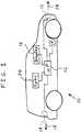
- FIG. 1there is shown one embodiment of a vehicle including a parking-assistance arrangement 10 of the present invention having a forward-looking camera 12, a backward-looking camera 14, a processor 16, a display 18, a steering sensor 19 and an audio speaker 20.
- Forward-looking camera 12maybe installed in the grille of the vehicle such that camera 12 faces, and is directed in, a forward direction 13.
- Backward-looking camera 14may be installed in the rear bumper of the vehicle such that camera 14 faces, and is directed in, a backward direction 15.
- the parking-assistance arrangementincludes only one of forward-looking camera 12 and backward-looking camera 14, but not both.
- Display 18may include an electronic computer screen or monitor, for example.
- the screen or monitormay be mounted on a dashboard of the vehicle, which may be an automobile.
- Processor 16may be in the form of and standard microprocessor, and may include a memory (not shown). Processor 16 may control the information or content that is displayed on the screen or monitor of display 18 and that is audibly output from speaker 20.
- the present inventionmay utilize static mapping.
- Camera(s) 12 and 14may constantly capture images of the environment as the vehicle moves.
- a typical image that is captured by forward-looking camera 12 and is displayed on display 18 while the driver is searching for a parking spaceis shown in FIG. 2 .
- This imagehappens to include an unoccupied parking space 21.
- a homographyor "projective transformation,” may be computed between the image plane and the actual ground plane.
- the homographymay be used to project each image, such as that shown in FIG. 2 , onto an estimated three-dimensional ground plane, as shown in the projected camera image of FIG. 3 .
- a discrete gridmay be aligned with, and superimposed onto, the ground plane.
- each grid cellmeasures five cm by five cm and collects all pixels whose centers are projected onto the cell within its boundaries.
- the griditself may have a finite height and width, and may be constantly re-centered on the camera as the camera moves through the scene.
- stored in memoryis an association between each cell and a linked list of the pixel values that have been recently observed at that cell location from all images.
- the pixel values that have been observed within a predetermined previous time periodmay be stored in memory, and the oldest pixel values may be replaced in memory with the most recently observed pixel values.
- Cells near the center of the imagemay collect a much higher number of observations than those cells to either side. In one embodiment, cells near the center of the image collect up to about 700 observations, while cells near the left-hand side perimeter or right-hand side perimeter collect only four or five observations.
- each grid cellcan then be computed in any of several different ways, and these cells may be combined to form a single bird's-eye view of the observed environment.
- the simplest aggregation techniqueis to select the most recently observed value in each cell.
- An example mapping resulting from this techniqueis illustrated in FIG. 4 , which is a map generated from a single forward-facing camera.
- using the mean or mode of the observed valuesmay reduce the distortions caused by obstacles that lie outside of (e.g., above) the ground plane, such as other vehicles. It is also possible to use the variance of values collected in a single cell to detect and possibly remove such distortions.
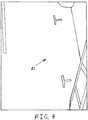
- FIG. 5is a map similar to FIG. 4 with at least some of the distortions caused by vehicles 24 and 26 removed.
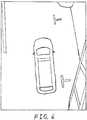
- FIG. 6is the mapping of FIG. 4 with an image or representation of the vehicle in which arrangement 10 is installed being superimposed or overlaid thereon.
- the vehicleit is also possible for the vehicle to be superimposed on the reduced-distortion version of FIG. 5 .
- the superimposed vehicle representationmay be drawn to scale and may be geometrically and positionally accurate so as to give the driver an accurate estimate of the vehicle's current position and size relative to any lane or parking markers on the road.
- the present inventionmay be applied to parking assistance. While the driver is looking for a parking spot for parallel parking, the system may constantly and continuously map the vehicle environment. Using the mapping and the described object detection, it is possible to measure the size of a parking spot from the map. The measured size of the parking space may be compared to the size of the driver's vehicle, and an indication may be provided to the driver as to whether the parking space is large enough to accommodate the driver's vehicle.
- the systemmay provide the driver with a visual and/or audible signal that a parking space has been found, and may further provide the driver with a visual and/or audible signal of the location and size of the parking space.
- the size of the parking spacemay be expressed relative to the size of the vehicle.
- the drivermay provide a threshold dimension or dimensions that a parking space must measure before the system indicates to the driver that the parking spot is available.
- the threshold dimension(s)may be expressed as a distance by which the parking space is larger than the vehicle.
- the systemmay keep records of the dimensions of previous parking spaces in which the vehicle has been successfully parallel parked, as well as the dimensions of previous parking spaces in which an attempt was made to park the vehicle, but the attempt was unsuccessful.
- the systemmay then provide the driver with an indication of the success rate of previous parallel parking attempts in similarly sized spaces. Because some drivers may be better at parallel parking than other drivers, the system may additionally keep such records of previous parallel parking by individual driver.
- the systemmay further provide the individual driver with his personal previous success rate in parking in spaces approximately the same size as the currently-identified spot.
- the parking spot and its sizemay be displayed on the map, as indicated by dashed lines in FIG. 7 .
- the parking spot and its dimensionsare represented by a rectangle provided on display 18.
- the position of the vehicle relative to the parking spotmay also be displayed on display 18.
- the systemmay provide the driver with spoken and/or visual instructions regarding recommended parking techniques. For example, the system may instruct the driver how far up the street that he should drive up before putting the vehicle in Reverse gear.
- a suggestion for the optimal path for parallel parkingmay be provided visually on display 18.
- the optimal pathmay be the path by which the vehicle may drive into the parking space with maximum clearance between the vehicle and obstructions such as other parked vehicles.
- display 18may also illustrate the path that the vehicle would take according to the current position of the steering wheel and/or tire, as sensed by steering sensor 19. Display 18 may continually follow and display the movements of the vehicle, thereby giving the driver feedback. The system may also instruct the driver regarding when and how far to turn the steering wheel while driving in Reverse gear.
- the screen display of FIG. 8illustrates an expected path 28, indicated in solid lines, of the driver's vehicle based on the steering position of tires 30a-b as sensed by steering sensor 19. At point 32 along expected path 28, the driver will need to turn sharply to the left in order to follow an optimal path 34, indicated in dashed lines, which branches off from expected path 28.
- expected path 28 of the driver's vehiclemay overlap and coincide with optimal path 34.
- expected path 28 and optimal pathmay be illustrated in the display separately when the two paths do not overlap or coincide.
- the display screen of FIG. 9illustrates a linear expected path 28 resulting from tires 30a-b being in their straightened position as compared to optimal path 34.
- text instructions to "TURN RIGHT SHARPLY"may be provided on the screen display as shown in FIG. 9 .
- speaker 20may emit audible spoken instructions to "turn right sharply.” These instructions to turn right may cease when the driver turns the steering wheel to the right sharply enough to cause expected path 28 to coincide with optimal path 34, as illustrated in FIG. 8 .
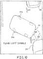
- FIG. 10illustrates an example screen display when the vehicle reaches point 32.
- Text instructions to "TURN LEFT SHARPLY"may be provided on the screen display as shown when the vehicle reaches point 32.
- speaker 20may emit audible spoken instructions to "turn left sharply.”
- An audible or visual warningmay be given to the driver when a pedestrian enters the parking zone.
- the presence of the pedestrianmay be detected by one of cameras 12, 14, or by an in-vehicle sonar system (not shown).
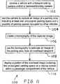
- FIG. 11An embodiment of a method 1100 of the present invention for assisting in parallel parking is illustrated in FIG. 11 .
- a vehicleis provided with a forward-looking camera and/or a backward-looking camera.
- the vehicle shown in FIG. 1includes a forward-looking camera 12 and a backward-looking camera 14.
- the camerais used to capture an image of a parking area including at least one unoccupied parking space and a plurality of parking spaces occupied by other vehicles.
- the image of FIG. 2which is captured by a camera, is of a parking area including an unoccupied parking space 21 and other parking spaces occupied by other vehicles, such as vehicles 24 and 26.
- a homography of the captured imageis created. That is, a projective transformation may be computed between the image plane of FIG. 2 and the ground plane.
- the ground planemay be thought of as the plane of the ground surface on which the parked cars are supported.
- the homographyis used to estimate an image of the parking area from an overhead viewpoint.
- the homographymay be used to transform the captured parking area image of FIG. 2 onto the ground plane to thereby estimate the overhead view of FIG. 3 .
- a portion of the overhead image including the unoccupied parking spaceis displayed on a display screen within a passenger compartment of the vehicle. That is, the overhead view of FIG. 3 may be further processed to recognize unoccupied parking space 21 and produce any of the images shown in FIGS. 4-10 .
- FIGS. 4-10includes unoccupied parking space 21, and any of FIGS. 4-10 maybe displayed on display screen 18.
- FIG. 12Another example of a method 1200 for displaying map information is illustrated in FIG. 12 .
- a vehicleis provided with a forward-looking camera and/or a backward-looking camera.
- the vehicle shown in FIG. 1includes a forward-looking camera 12 and a backward-looking camera 14.
- the camerais used to capture images of a surrounding area.
- the image of FIG. 2which is captured by a camera, is of a parking area surrounding the driver's vehicle.
- a homography of the captured imageis created. That is, a projective transformation may be computed between the image plane of FIG. 2 and the ground plane.
- the ground planemay be thought of as the plane of the ground surface on which the parked cars are supported.
- the homographyis used to estimate an image of the parking area from an overhead viewpoint.
- the homographymay be used to transform the captured parking area image of FIG. 2 onto the ground plane to thereby estimate the overhead view of FIG. 3 .
- positions of the vehicleare determined relative to the overhead images as the vehicle moves.
- the position of the vehicle relative to the overhead imagesmay be determined in any of various ways, including: calculating the current vehicle position based on the images currently captured by the camera(s); using distance sensors such as sonar or LIDAR on the driver's vehicle which sense the positions of the parked cars; and/or tracking the distance and direction traveled by the driver's vehicle based on odometer and steering sensor outputs since the area currently in the overhead view was last in the field of view of the camera (assuming an initial distance between the driver's vehicle and the unoccupied parking space is calculated based on sonar and/or the initially captured image of the unoccupied parking space).
- the overhead imagesare displayed on a display screen within a passenger compartment of the vehicle, the displayed overhead images including real time representations of the vehicle, positions of the vehicle representations within the overhead images being substantially continuously updated based on the determining step. That is, the overhead images such as those shown in FIGS. 6 and 8-10 are displayed on display screen 18 within the a passenger compartment of the vehicle. In one example, display screen 18 is mounted on the dashboard.
- Each of the displayed overhead images of FIGS. 6 and 8-10may include real time representations of the driver's vehicle. Positions of the vehicle representations within the overhead images of FIGS. 6 and 8-10 may be continuously updated based on the latest actual positions of the driver's vehicle as determined using the latest input data.
- the present inventionhas been described herein as being applied to assisting a driver in executing a parking maneuver. However, it is to be understood that the present invention may be applied to other applications, such as warning the driver of the exact locations of nearby pedestrians, or automatically preventing the driver from driving into a pedestrian.
Landscapes
- Engineering & Computer Science (AREA)
- Mechanical Engineering (AREA)
- Multimedia (AREA)
- Theoretical Computer Science (AREA)
- Transportation (AREA)
- Combustion & Propulsion (AREA)
- Chemical & Material Sciences (AREA)
- Physics & Mathematics (AREA)
- Signal Processing (AREA)
- Computing Systems (AREA)
- Geometry (AREA)
- Computer Graphics (AREA)
- General Physics & Mathematics (AREA)
- Traffic Control Systems (AREA)
- Image Processing (AREA)
- Closed-Circuit Television Systems (AREA)
Description
- The present invention relates to camera systems for use in vehicles, and, more particularly, to camera systems for use in parking of vehicles.
- Nissan has developed a driver assistance system called "Nissan Around View Monitor" which employs four ultra-wide high-resolution cameras mounted in the front, rear and both sides of the vehicle to provide a bird's eye view of the vehicle's surroundings. All those images are processed and displayed in real time on a dash-mounted screen, giving drivers a 360 degree view of obstacles surrounding the vehicle which they may want to avoid hitting. Shifting the car into reverse or drive alternates between a view of the front or rear. Drivers are able to toggle the left, front and right views when performing a particularly tricky parallel parking maneuver. The first application of Nissan's "Around View Monitor" in the United States is in the Infiniti EX35 model.
- Mapping is a technique used by robots and vehicles to build up a map within an unknown environment. This is not as straightforward as it might sound due to inherent uncertainties in discerning the robot's relative movement from its various sensors. A system for mapping road surfaces may include high-end LIDAR, GPS and Inertial Measurement Unit (IMU) sensors. The system may produce a two-dimensional surface image of ground reflectivity with five centimeter resolution of the road surface.
- Other known systems focus on generating bird's eye views of urban and rural terrains by use of cameras mounted on either aircraft or satellites. The most common approach is pushbroom mosaicking, which works well for applications wherein the desired viewpoint of the final mosaic is close to the original viewpoint.
- Some commercial offerings, such as Google's "Street View" or Microsoft's "Street Side", create static maps of urban scenes. The focus in these systems is on providing views of the urban city similar to what an automobile passenger or pedestrian might see moving around the same city. The differences in perspective between the captured and final images are small if any and all processing can be done offline.
- Other systems have been proposed that generate maps using sparse feature representations, sometimes referred to as landmarks. In particular, several attempts at vSLAM (visual simultaneous localization and mapping) have been developed and demonstrated, primarily in indoor environments that use camera systems to create feature based maps. In general, these feature-based maps are unusable by a human attempting to localize himself or his vehicle.
- Forward-looking automotive cameras are used in various applications including night vision assistance, lane detection, lane departure warning, lane keeping, and road sign detection. In the future, such cameras will be standard in upper class vehicles. Backward-facing cameras are already used as a visual aid for backing up and may be required in the future for backover avoidance.
- Various approaches to parking assistance exist. These approaches have in common that sonar is used as the main sensor. The advantage of sonar is that it is inexpensive. The disadvantage of sonar is that sonar measurements are noisy and inaccurate, which sometimes leads to false system behavior. Existing systems issue a visual and/or audible warning to the driver before a collision with an object. Future systems will assist the driver by operating the steering (i.e., semi-autonomous parking) or steering plus gas/brakes (i.e., fully autonomous parking).
- BMW has presented a camera-based system for parking assistance using motion-stereo. This system requires additional sideward-facing cameras in order to detect the parking area.
US 2008/136673 discloses a method and an apparatus for recognizing a parking slot by using a bird's-eye view and a parking assist system using the same.- What is neither disclosed nor suggested by the prior art is a method for utilizing a forward-facing camera and/or a backward-facing camera in providing a driver with an overhead view for assistance in parallel parking.
- The present invention may provide a system including a forward and/or backward facing camera to assist a vehicle driver during parallel parking.
- The invention comprises, in one form thereof, a method for assisting in parallel parking, including providing a vehicle with a forward-looking camera and/or a backward-looking camera. The camera is used to capture an image of a parking area including at least one unoccupied parking space and a plurality of parking spaces occupied by other vehicles. A homography of the captured image is created. The homography is used to estimate an image of the parking area from an overhead viewpoint. A portion of the overhead image including the unoccupied parking space is displayed on a display screen within a passenger compartment of the vehicle.
- The invention comprises, in another form thereof, an electronic parking-assistance arrangement for a vehicle. The arrangement includes a forward-looking camera and/or a backward-looking camera provided in the vehicle. A processor is coupled to at least one camera. The processor receives first images of a parking area. The images are captured by the camera from a substantially horizontal viewpoint. The processor translates the first images into second images from a substantially vertical viewpoint. An unoccupied parking space within the second images is identified. A representation of the vehicle is superimposed onto the second images when the vehicle is substantially adjacent to the unoccupied parking space. A position of the vehicle representation relative to the unoccupied parking space in the second images is continuously updated to indicate an actual position of the vehicle relative to the unoccupied parking space. A display screen is provided in a passenger compartment of the vehicle and is coupled to the processor. The display screen receives and displays the second images with the superimposed representations of the vehicle.
- The invention comprises, in yet another form thereof, a method of displaying map information, including providing a vehicle with a forward-looking camera and/or a backward-looking camera. The camera is used to capture images of a surrounding area. Homographies of the captured images are created. The homographies are used to estimate images of the area from an overhead viewpoint. Positions of the vehicle relative to the overhead images as the vehicle moves are determined. The overhead images are displayed on a display screen within a passenger compartment of the vehicle. The displayed overhead images include real time representations of the vehicle. Positions of the vehicle representations within the overhead images are substantially continuously updated based on the determining step.
- An advantage of the present invention is that it requires fewer sensors than do known systems and is therefore significantly cheaper than known systems. Specifically, the present invention may utilize only a forward- and/or a backward-looking camera.
- Another advantage of the present invention is that it utilizes equipment that will be standard equipment on future vehicles, and does not require additional hardware. More particularly, both forward-looking and backward-looking cameras will be standard equipment in future automobiles. The forward-looking camera is used for night vision, lane detection, road sign detection, etc. The backward-looking camera is typically used for backover avoidance and may be required in future cars. See, for example, the guidance provided by the National Highway Traffic Safety Administration regarding Backover Avoidance. Thus, the present invention may provide an additional value benefit through software and may use only existing hardware.
- The above mentioned and other features and objects of this invention, and the manner of attaining them, will become more apparent and the invention itself will be better understood by reference to the following description of embodiments of the invention taken in conjunction with the accompanying drawings, wherein:
FIG. 1 is a schematic plan view of a vehicle including one embodiment of a parking-assistance arrangement of the present invention.FIG. 2 is an example image that is captured by the forward-looking camera of the parking-assistance arrangement ofFIG. 1 .FIG. 3 is a projection of the image ofFIG. 2 onto an estimated three-dimensional ground plane by use of homography, according to one embodiment of the present invention.FIG. 4 is an example mapping resulting from one embodiment of a method of the present invention.FIG. 5 is an example mapping resulting from another embodiment of a method of the present invention.FIG. 6 is the mapping ofFIG. 4 with an image of the vehicle ofFIG. 1 superimposed thereon.FIG. 7 is an example mapping resulting from yet another embodiment of a method of the present invention.FIG. 8 is an example mapping resulting from still another embodiment of a method of the present invention.FIG. 9 is the example mapping ofFIG. 8 with the tires of the driver's vehicle in the straightened position.FIG. 10 is the example mapping ofFIG. 8 at a point where the driver's vehicle must turn the steering wheel to the left in order to follow an optimal parking path.FIG. 11 is a flow chart illustrating one method of the present invention for assisting in parallel parking.FIG. 12 is a flow chart illustrating one method for displaying map information.- Corresponding reference characters indicate corresponding parts throughout the several views. Although the exemplification set out herein illustrates embodiments of the invention, in several forms, the embodiments disclosed below are not intended to be exhaustive or to be construed as limiting the scope of the invention to the precise forms disclosed.
- Referring now to the drawings, and particularly to
FIG. 1 , there is shown one embodiment of a vehicle including a parking-assistance arrangement 10 of the present invention having a forward-lookingcamera 12, a backward-lookingcamera 14, aprocessor 16, adisplay 18, asteering sensor 19 and anaudio speaker 20. Forward-lookingcamera 12 maybe installed in the grille of the vehicle such thatcamera 12 faces, and is directed in, aforward direction 13. Backward-lookingcamera 14 may be installed in the rear bumper of the vehicle such thatcamera 14 faces, and is directed in, abackward direction 15. In some embodiments, the parking-assistance arrangement includes only one of forward-lookingcamera 12 and backward-lookingcamera 14, but not both. Display 18 may include an electronic computer screen or monitor, for example. In one embodiment, the screen or monitor may be mounted on a dashboard of the vehicle, which may be an automobile.Processor 16 may be in the form of and standard microprocessor, and may include a memory (not shown).Processor 16 may control the information or content that is displayed on the screen or monitor ofdisplay 18 and that is audibly output fromspeaker 20.- The present invention may utilize static mapping. Camera(s) 12 and 14 may constantly capture images of the environment as the vehicle moves. A typical image that is captured by forward-looking
camera 12 and is displayed ondisplay 18 while the driver is searching for a parking space is shown inFIG. 2 . This image happens to include anunoccupied parking space 21. Given the relative position ofcamera 12 in the vehicle, a homography, or "projective transformation," may be computed between the image plane and the actual ground plane. The homography may be used to project each image, such as that shown inFIG. 2 , onto an estimated three-dimensional ground plane, as shown in the projected camera image ofFIG. 3 . - In order to collect data across multiple frames at high resolution, a discrete grid, as fragmentarily indicated at 22, may be aligned with, and superimposed onto, the ground plane. In one particular embodiment, each grid cell measures five cm by five cm and collects all pixels whose centers are projected onto the cell within its boundaries. The grid itself may have a finite height and width, and may be constantly re-centered on the camera as the camera moves through the scene.
- In one embodiment, stored in memory is an association between each cell and a linked list of the pixel values that have been recently observed at that cell location from all images. The pixel values that have been observed within a predetermined previous time period may be stored in memory, and the oldest pixel values may be replaced in memory with the most recently observed pixel values. Cells near the center of the image (and consequently the center of the grid) may collect a much higher number of observations than those cells to either side. In one embodiment, cells near the center of the image collect up to about 700 observations, while cells near the left-hand side perimeter or right-hand side perimeter collect only four or five observations.
- The final value of each grid cell can then be computed in any of several different ways, and these cells may be combined to form a single bird's-eye view of the observed environment. The simplest aggregation technique is to select the most recently observed value in each cell. An example mapping resulting from this technique is illustrated in
FIG. 4 , which is a map generated from a single forward-facing camera. - In other embodiments, using the mean or mode of the observed values may reduce the distortions caused by obstacles that lie outside of (e.g., above) the ground plane, such as other vehicles. It is also possible to use the variance of values collected in a single cell to detect and possibly remove such distortions.
FIG. 5 is a map similar toFIG. 4 with at least some of the distortions caused byvehicles - A map that may be used by the driver is illustrated in
FIG. 6 , which is the mapping ofFIG. 4 with an image or representation of the vehicle in whicharrangement 10 is installed being superimposed or overlaid thereon. However, it is also possible for the vehicle to be superimposed on the reduced-distortion version ofFIG. 5 . The superimposed vehicle representation may be drawn to scale and may be geometrically and positionally accurate so as to give the driver an accurate estimate of the vehicle's current position and size relative to any lane or parking markers on the road. - As described above, the present invention may be applied to parking assistance. While the driver is looking for a parking spot for parallel parking, the system may constantly and continuously map the vehicle environment. Using the mapping and the described object detection, it is possible to measure the size of a parking spot from the map. The measured size of the parking space may be compared to the size of the driver's vehicle, and an indication may be provided to the driver as to whether the parking space is large enough to accommodate the driver's vehicle.
- The system may provide the driver with a visual and/or audible signal that a parking space has been found, and may further provide the driver with a visual and/or audible signal of the location and size of the parking space. The size of the parking space may be expressed relative to the size of the vehicle.
- In one embodiment, the driver may provide a threshold dimension or dimensions that a parking space must measure before the system indicates to the driver that the parking spot is available. The threshold dimension(s) may be expressed as a distance by which the parking space is larger than the vehicle.
- In another embodiment, the system may keep records of the dimensions of previous parking spaces in which the vehicle has been successfully parallel parked, as well as the dimensions of previous parking spaces in which an attempt was made to park the vehicle, but the attempt was unsuccessful. The system may then provide the driver with an indication of the success rate of previous parallel parking attempts in similarly sized spaces. Because some drivers may be better at parallel parking than other drivers, the system may additionally keep such records of previous parallel parking by individual driver. The system may further provide the individual driver with his personal previous success rate in parking in spaces approximately the same size as the currently-identified spot.
- The parking spot and its size may be displayed on the map, as indicated by dashed lines in
FIG. 7 . In this particular embodiment, the parking spot and its dimensions are represented by a rectangle provided ondisplay 18. The position of the vehicle relative to the parking spot may also be displayed ondisplay 18. - The system may provide the driver with spoken and/or visual instructions regarding recommended parking techniques. For example, the system may instruct the driver how far up the street that he should drive up before putting the vehicle in Reverse gear. A suggestion for the optimal path for parallel parking may be provided visually on
display 18. The optimal path may be the path by which the vehicle may drive into the parking space with maximum clearance between the vehicle and obstructions such as other parked vehicles. - In addition to the optimal path,
display 18 may also illustrate the path that the vehicle would take according to the current position of the steering wheel and/or tire, as sensed by steeringsensor 19.Display 18 may continually follow and display the movements of the vehicle, thereby giving the driver feedback. The system may also instruct the driver regarding when and how far to turn the steering wheel while driving in Reverse gear. For example, the screen display ofFIG. 8 illustrates an expectedpath 28, indicated in solid lines, of the driver's vehicle based on the steering position oftires 30a-b as sensed by steeringsensor 19. Atpoint 32 along expectedpath 28, the driver will need to turn sharply to the left in order to follow anoptimal path 34, indicated in dashed lines, which branches off from expectedpath 28. - In
FIG. 9 , expectedpath 28 of the driver's vehicle may overlap and coincide withoptimal path 34. However, in one embodiment, expectedpath 28 and optimal path may be illustrated in the display separately when the two paths do not overlap or coincide. As an example, the display screen ofFIG. 9 illustrates a linear expectedpath 28 resulting fromtires 30a-b being in their straightened position as compared tooptimal path 34. Because of the divergence of expectedpath 28 fromoptimal path 34, text instructions to "TURN RIGHT SHARPLY" may be provided on the screen display as shown inFIG. 9 . In addition, or alternatively,speaker 20 may emit audible spoken instructions to "turn right sharply." These instructions to turn right may cease when the driver turns the steering wheel to the right sharply enough to cause expectedpath 28 to coincide withoptimal path 34, as illustrated inFIG. 8 . FIG. 10 illustrates an example screen display when the vehicle reachespoint 32. Text instructions to "TURN LEFT SHARPLY" may be provided on the screen display as shown when the vehicle reachespoint 32. In addition, or alternatively,speaker 20 may emit audible spoken instructions to "turn left sharply."- An audible or visual warning may be given to the driver when a pedestrian enters the parking zone. The presence of the pedestrian may be detected by one of
cameras - An embodiment of a
method 1100 of the present invention for assisting in parallel parking is illustrated inFIG. 11 . In afirst step 1102, a vehicle is provided with a forward-looking camera and/or a backward-looking camera. For example, the vehicle shown inFIG. 1 includes a forward-lookingcamera 12 and a backward-lookingcamera 14. - In a
next step 1104, the camera is used to capture an image of a parking area including at least one unoccupied parking space and a plurality of parking spaces occupied by other vehicles. For example, the image ofFIG. 2 , which is captured by a camera, is of a parking area including anunoccupied parking space 21 and other parking spaces occupied by other vehicles, such asvehicles - Next, in
step 1106, a homography of the captured image is created. That is, a projective transformation may be computed between the image plane ofFIG. 2 and the ground plane. In this context, the ground plane may be thought of as the plane of the ground surface on which the parked cars are supported. - In
step 1108, the homography is used to estimate an image of the parking area from an overhead viewpoint. For example, the homography may be used to transform the captured parking area image ofFIG. 2 onto the ground plane to thereby estimate the overhead view ofFIG. 3 . - In a final step 1110, a portion of the overhead image including the unoccupied parking space is displayed on a display screen within a passenger compartment of the vehicle. That is, the overhead view of
FIG. 3 may be further processed to recognizeunoccupied parking space 21 and produce any of the images shown inFIGS. 4-10 . Each ofFIGS. 4-10 includesunoccupied parking space 21, and any ofFIGS. 4-10 maybe displayed ondisplay screen 18. - Another example of a
method 1200 for displaying map information is illustrated inFIG. 12 . In afirst step 1202, a vehicle is provided with a forward-looking camera and/or a backward-looking camera. For example, the vehicle shown inFIG. 1 includes a forward-lookingcamera 12 and a backward-lookingcamera 14. - In a
next step 1204, the camera is used to capture images of a surrounding area. For example, the image ofFIG. 2 , which is captured by a camera, is of a parking area surrounding the driver's vehicle. - Next, in
step 1206, a homography of the captured image is created. That is, a projective transformation may be computed between the image plane ofFIG. 2 and the ground plane. In this context, the ground plane may be thought of as the plane of the ground surface on which the parked cars are supported. - In
step 1208, the homography is used to estimate an image of the parking area from an overhead viewpoint. For example, the homography may be used to transform the captured parking area image ofFIG. 2 onto the ground plane to thereby estimate the overhead view ofFIG. 3 . - In a
next step 1210, positions of the vehicle are determined relative to the overhead images as the vehicle moves. The position of the vehicle relative to the overhead images may be determined in any of various ways, including: calculating the current vehicle position based on the images currently captured by the camera(s); using distance sensors such as sonar or LIDAR on the driver's vehicle which sense the positions of the parked cars; and/or tracking the distance and direction traveled by the driver's vehicle based on odometer and steering sensor outputs since the area currently in the overhead view was last in the field of view of the camera (assuming an initial distance between the driver's vehicle and the unoccupied parking space is calculated based on sonar and/or the initially captured image of the unoccupied parking space). - In a
final step 1212, the overhead images are displayed on a display screen within a passenger compartment of the vehicle, the displayed overhead images including real time representations of the vehicle, positions of the vehicle representations within the overhead images being substantially continuously updated based on the determining step. That is, the overhead images such as those shown inFIGS. 6 and8-10 are displayed ondisplay screen 18 within the a passenger compartment of the vehicle. In one example,display screen 18 is mounted on the dashboard. Each of the displayed overhead images ofFIGS. 6 and8-10 may include real time representations of the driver's vehicle. Positions of the vehicle representations within the overhead images ofFIGS. 6 and8-10 may be continuously updated based on the latest actual positions of the driver's vehicle as determined using the latest input data. - The present invention has been described herein as being applied to assisting a driver in executing a parking maneuver. However, it is to be understood that the present invention may be applied to other applications, such as warning the driver of the exact locations of nearby pedestrians, or automatically preventing the driver from driving into a pedestrian.
Claims (11)
- A method for assisting in vehicle parking, comprising the steps of:providing a vehicle (10) with at least one of a forward-looking camera (12, 112) and a backward-looking camera (14);using the forward-looking camera (12, 112) to capture an image of a parking area including at least one unoccupied parking space (21) and a plurality of parking spaces occupied by other vehicles (24, 26);creating a homography of the captured image;using the homography to estimate an image of the parking area from an overhead viewpoint;displaying a portion of the overhead image including the unoccupied parking space (21) on a display screen (18) within a passenger compartment of the vehicle (10);the methodcharacterized in that it further comprises the step of:providing a representation of a current location of the vehicle (10) in the overhead image;determining positions of the vehicle (10) relative to the overhead images as the vehicle (10) moves,wherein the displayed overhead images include real time representations of the vehicle (10), anddividing the homography into substantially identical grids of cells.
- The method of Claim 1, comprising the further step of automatically detecting the unoccupied parking space (21) in the overhead image.
- The method of Claim 1, wherein the representation of the current location of the vehicle (10) in the overhead image is continuously updated.
- The method of Claim 1, comprising the further steps of:calculating a path for the vehicle (10) to take to drive into the unoccupied parking space (21); anddisplaying the path on the display screen (18).
- The method of claim 1, wherein positions of the vehicle (10) representations within the overhead images are substantially continuously updated based on the determining step.
- The method of Claim 1, wherein the displaying step is dependent upon one of a mean, mode and variance of pixel values in corresponding cells.
- The method of Claim 1, wherein the at least one of a forward-looking camera (12, 112) and a backward-looking camera (14) comprises a forward-looking camera (12) used for at least one of night vision, lane detection and road sign detection.
- The method of Claim 1, wherein the at least one of a forward-looking camera (12, 112) and a backward-looking camera (14) comprises a backward-looking camera (14) used for backover avoidance.
- The method of Claim 1 comprising the further steps of:measuring a size of the unoccupied parking space (21), the measuring being performed on the captured image and/or the overhead image;comparing the measured size of the unoccupied parking space (21) to a size of the vehicle (10); andproviding to a user an indication of whether the unoccupied parking space (21) is large enough to accommodate the vehicle (10), the providing of the indication being dependent upon the comparing step.
- The method of Claim 9 comprising the further step of receiving from the user a minimum distance by which the measured size of the unoccupied parking space (21) should exceed the vehicle size in order for the indication to be provided that the unoccupied parking space (21) is large enough to accommodate the vehicle (10), the providing of the indication being dependent upon the received minimum distance.
- The method of Claim 1 comprising the further steps of:measuring a size of the unoccupied parking space (21), the measuring being performed on the captured image and/or the overhead image; andproviding an indication to a user of a success rate of previous parallel parking attempts in unoccupied parking spaces having sizes substantially equal to the measured size.
Applications Claiming Priority (2)
| Application Number | Priority Date | Filing Date | Title |
|---|---|---|---|
| US12/463,699US8289189B2 (en) | 2009-05-11 | 2009-05-11 | Camera system for use in vehicle parking |
| PCT/US2010/034141WO2010132314A2 (en) | 2009-05-11 | 2010-05-07 | Camera system for use in vehicle parking |
Publications (2)
| Publication Number | Publication Date |
|---|---|
| EP2429877A2 EP2429877A2 (en) | 2012-03-21 |
| EP2429877B1true EP2429877B1 (en) | 2020-03-11 |
Family
ID=43062036
Family Applications (1)
| Application Number | Title | Priority Date | Filing Date |
|---|---|---|---|
| EP10728015.8AActiveEP2429877B1 (en) | 2009-05-11 | 2010-05-07 | Camera system for use in vehicle parking |
Country Status (5)
| Country | Link |
|---|---|
| US (1) | US8289189B2 (en) |
| EP (1) | EP2429877B1 (en) |
| JP (1) | JP5620472B2 (en) |
| CN (1) | CN102458964B (en) |
| WO (1) | WO2010132314A2 (en) |
Families Citing this family (62)
| Publication number | Priority date | Publication date | Assignee | Title |
|---|---|---|---|---|
| DE102005030838A1 (en)* | 2005-07-01 | 2007-01-04 | Siemens Ag | Night Vision System |
| US10878646B2 (en) | 2005-12-08 | 2020-12-29 | Smartdrive Systems, Inc. | Vehicle event recorder systems |
| US8996240B2 (en) | 2006-03-16 | 2015-03-31 | Smartdrive Systems, Inc. | Vehicle event recorders with integrated web server |
| US9201842B2 (en) | 2006-03-16 | 2015-12-01 | Smartdrive Systems, Inc. | Vehicle event recorder systems and networks having integrated cellular wireless communications systems |
| US8649933B2 (en) | 2006-11-07 | 2014-02-11 | Smartdrive Systems Inc. | Power management systems for automotive video event recorders |
| US8989959B2 (en) | 2006-11-07 | 2015-03-24 | Smartdrive Systems, Inc. | Vehicle operator performance history recording, scoring and reporting systems |
| US8868288B2 (en) | 2006-11-09 | 2014-10-21 | Smartdrive Systems, Inc. | Vehicle exception event management systems |
| US8239092B2 (en) | 2007-05-08 | 2012-08-07 | Smartdrive Systems Inc. | Distributed vehicle event recorder systems having a portable memory data transfer system |
| US20100328464A1 (en)* | 2009-06-30 | 2010-12-30 | Tech-Cast Mfg. Corp. | Car-mount traffic condition surveillance device |
| JP5696872B2 (en)* | 2010-03-26 | 2015-04-08 | アイシン精機株式会社 | Vehicle periphery monitoring device |
| US20120056995A1 (en)* | 2010-08-31 | 2012-03-08 | Texas Instruments Incorporated | Method and Apparatus for Stereo-Based Proximity Warning System for Vehicle Safety |
| US8766818B2 (en) | 2010-11-09 | 2014-07-01 | International Business Machines Corporation | Smart spacing allocation |
| US9854209B2 (en) | 2011-04-19 | 2017-12-26 | Ford Global Technologies, Llc | Display system utilizing vehicle and trailer dynamics |
| US9926008B2 (en) | 2011-04-19 | 2018-03-27 | Ford Global Technologies, Llc | Trailer backup assist system with waypoint selection |
| US20150197281A1 (en)* | 2011-04-19 | 2015-07-16 | Ford Global Technologies, Llc | Trailer backup assist system with lane marker detection |
| EP2723069B1 (en)* | 2011-06-16 | 2017-10-18 | Aisin Seiki Kabushiki Kaisha | Vehicle periphery monitoring device |
| KR20130019639A (en)* | 2011-08-17 | 2013-02-27 | 엘지이노텍 주식회사 | Camera apparatus of vehicle |
| CN103826929B (en)* | 2011-09-22 | 2016-08-17 | 日产自动车株式会社 | vehicle control device |
| US8996234B1 (en) | 2011-10-11 | 2015-03-31 | Lytx, Inc. | Driver performance determination based on geolocation |
| US9298575B2 (en) | 2011-10-12 | 2016-03-29 | Lytx, Inc. | Drive event capturing based on geolocation |
| US9418552B2 (en) | 2011-12-14 | 2016-08-16 | Hi-Park Solutions Ltd. | Method and system for automatically locating vacant parking places |
| KR101478067B1 (en)* | 2012-03-21 | 2015-01-02 | 주식회사 만도 | Smart Parking Assist System of Vehicle and Control Method Thereof |
| US9598836B2 (en) | 2012-03-29 | 2017-03-21 | Harnischfeger Technologies, Inc. | Overhead view system for a shovel |
| KR101877570B1 (en)* | 2012-04-04 | 2018-07-11 | 현대자동차주식회사 | Apparatus for setting parking position based on around view image and method thereof |
| US9728228B2 (en) | 2012-08-10 | 2017-08-08 | Smartdrive Systems, Inc. | Vehicle event playback apparatus and methods |
| KR101401399B1 (en)* | 2012-10-12 | 2014-05-30 | 현대모비스 주식회사 | Parking Assist Apparatus and Parking Assist Method and Parking Assist System Using the Same |
| US9344683B1 (en)* | 2012-11-28 | 2016-05-17 | Lytx, Inc. | Capturing driving risk based on vehicle state and automatic detection of a state of a location |
| US9165208B1 (en)* | 2013-03-13 | 2015-10-20 | Hrl Laboratories, Llc | Robust ground-plane homography estimation using adaptive feature selection |
| US9013286B2 (en)* | 2013-09-23 | 2015-04-21 | Volkswagen Ag | Driver assistance system for displaying surroundings of a vehicle |
| US9501878B2 (en) | 2013-10-16 | 2016-11-22 | Smartdrive Systems, Inc. | Vehicle event playback apparatus and methods |
| US9610955B2 (en) | 2013-11-11 | 2017-04-04 | Smartdrive Systems, Inc. | Vehicle fuel consumption monitor and feedback systems |
| CN103723194A (en)* | 2013-12-13 | 2014-04-16 | 浙江吉利控股集团有限公司 | Automobile reverse-driving tire position monitoring device and reverse driving assisting device |
| US8892310B1 (en) | 2014-02-21 | 2014-11-18 | Smartdrive Systems, Inc. | System and method to detect execution of driving maneuvers |
| JP6303784B2 (en)* | 2014-05-09 | 2018-04-04 | 日産自動車株式会社 | Parking assistance device and parking assistance method |
| US9663127B2 (en) | 2014-10-28 | 2017-05-30 | Smartdrive Systems, Inc. | Rail vehicle event detection and recording system |
| US11069257B2 (en) | 2014-11-13 | 2021-07-20 | Smartdrive Systems, Inc. | System and method for detecting a vehicle event and generating review criteria |
| US20160176340A1 (en)* | 2014-12-17 | 2016-06-23 | Continental Automotive Systems, Inc. | Perspective shifting parking camera system |
| KR102227855B1 (en)* | 2015-01-22 | 2021-03-15 | 현대모비스 주식회사 | Parking guide system and method for controlling the same |
| US9725116B2 (en) | 2015-03-27 | 2017-08-08 | Ford Global Technologies, Llc | Vehicle and vehicle parking system |
| US9679420B2 (en) | 2015-04-01 | 2017-06-13 | Smartdrive Systems, Inc. | Vehicle event recording system and method |
| IL240831A (en) | 2015-08-25 | 2017-03-30 | Elbit Systems Ltd | System and method for identifying a deviation of an operator of a vehicle from a doctrine |
| WO2017068699A1 (en)* | 2015-10-22 | 2017-04-27 | 日産自動車株式会社 | Parking space line detection method and device |
| US10683035B2 (en)* | 2015-12-08 | 2020-06-16 | Panasonic Intellectual Property Management Co., Ltd. | Parking assistance device, parking assistance method, and non-transitory computer readable medium |
| CN105355083A (en)* | 2015-12-14 | 2016-02-24 | 宁波裕兰信息科技有限公司 | Vision-based 360-degree parking assist intelligent guiding system |
| US10325502B2 (en)* | 2016-02-10 | 2019-06-18 | Ford Global Technologies, Llc | Parallel parking assistant |
| KR102513745B1 (en)* | 2016-04-15 | 2023-03-24 | 주식회사 에이치엘클레무브 | Driving assistance device |
| US10368036B2 (en)* | 2016-11-17 | 2019-07-30 | Vivotek Inc. | Pair of parking area sensing cameras, a parking area sensing method and a parking area sensing system |
| CN106740632A (en)* | 2016-11-28 | 2017-05-31 | 芜湖市吉安汽车电子销售有限公司 | A kind of vehicle-mounted reverse image system |
| KR101915165B1 (en)* | 2016-12-30 | 2018-11-06 | 현대자동차주식회사 | Automatically parking system and automatically parking method |
| KR102046468B1 (en)* | 2017-07-26 | 2019-11-18 | 엘지전자 주식회사 | Side mirror for vehicle |
| JP6958117B2 (en)* | 2017-08-29 | 2021-11-02 | 株式会社アイシン | Parking support device |
| US10737725B2 (en)* | 2017-09-27 | 2020-08-11 | Gentex Corporation | System and method for assisting parallel parking using orthogonal projection |
| CN108297794B (en)* | 2018-01-11 | 2022-11-18 | 阿尔派株式会社 | Parking assistance device and travel prediction line display method |
| CN108528441B (en)* | 2018-03-27 | 2020-02-07 | 广州汽车集团股份有限公司 | Parking method and device |
| US10900857B2 (en)* | 2018-06-06 | 2021-01-26 | Ford Global Technologies, Llc | Methods and systems for fluid leak determination |
| DE102018214874B3 (en)* | 2018-08-31 | 2019-12-19 | Audi Ag | Method and arrangement for generating an environment map of a vehicle textured with image information and vehicle comprising such an arrangement |
| DE102018131106A1 (en)* | 2018-12-06 | 2020-06-10 | Valeo Schalter Und Sensoren Gmbh | Method for recognizing a parking area for a vehicle by separately recognizing elements of a parking area marking, computing device and driver assistance system |
| US10713509B1 (en) | 2019-01-24 | 2020-07-14 | Ford Global Technologies, Llc | Parking assist system with parking spot occupancy readout |
| US11301948B2 (en) | 2019-04-01 | 2022-04-12 | International Business Machines Corporation | Parking continuity with unused duration between automated vehicles |
| CN113034963B (en)* | 2021-03-02 | 2022-08-02 | 英博超算(南京)科技有限公司 | Vision parking stall tracking system |
| JP2023131351A (en)* | 2022-03-09 | 2023-09-22 | 株式会社ジェイテクト | Steering control device |
| CN118212613B (en)* | 2024-03-14 | 2025-03-18 | 广州小鹏自动驾驶科技有限公司 | Parking space detection method, device, vehicle and storage medium |
Family Cites Families (14)
| Publication number | Priority date | Publication date | Assignee | Title |
|---|---|---|---|---|
| JP4114292B2 (en)* | 1998-12-03 | 2008-07-09 | アイシン・エィ・ダブリュ株式会社 | Driving support device |
| US7366595B1 (en)* | 1999-06-25 | 2008-04-29 | Seiko Epson Corporation | Vehicle drive assist system |
| JP2001213253A (en)* | 2000-01-31 | 2001-08-07 | Equos Research Co Ltd | Vehicle parking operation assist device |
| JP3977368B2 (en)* | 2004-09-30 | 2007-09-19 | クラリオン株式会社 | Parking assistance system |
| JP2006341641A (en)* | 2005-06-07 | 2006-12-21 | Nissan Motor Co Ltd | Video display device and video display method |
| KR101143176B1 (en)* | 2006-09-14 | 2012-05-08 | 주식회사 만도 | Method and Apparatus for Recognizing Parking Slot Marking by Using Bird's Eye View and Parking Assist System Using Same |
| JP2008187564A (en)* | 2007-01-31 | 2008-08-14 | Sanyo Electric Co Ltd | Camera calibration apparatus and method, and vehicle |
| JP5182545B2 (en)* | 2007-05-16 | 2013-04-17 | アイシン精機株式会社 | Parking assistance device |
| JP5003946B2 (en)* | 2007-05-30 | 2012-08-22 | アイシン精機株式会社 | Parking assistance device |
| JP2009100342A (en)* | 2007-10-18 | 2009-05-07 | Sanyo Electric Co Ltd | Camera calibration device, method and vehicle |
| JP2009129001A (en)* | 2007-11-20 | 2009-06-11 | Sanyo Electric Co Ltd | Driving support system, vehicle, solid object region estimation method |
| US20090187300A1 (en)* | 2008-01-22 | 2009-07-23 | David Wayne Everitt | Integrated vehicle computer system |
| KR20090088210A (en)* | 2008-02-14 | 2009-08-19 | 주식회사 만도 | Target parking position detection method and device using two reference points and parking assistance system using the same |
| CN101425181B (en)* | 2008-12-15 | 2012-05-09 | 浙江大学 | Panoramic view vision auxiliary parking system demarcating method |
- 2009
- 2009-05-11USUS12/463,699patent/US8289189B2/enactiveActive
- 2010
- 2010-05-07CNCN201080025014.9Apatent/CN102458964B/enactiveActive
- 2010-05-07WOPCT/US2010/034141patent/WO2010132314A2/enactiveApplication Filing
- 2010-05-07EPEP10728015.8Apatent/EP2429877B1/enactiveActive
- 2010-05-07JPJP2012510887Apatent/JP5620472B2/enactiveActive
Non-Patent Citations (1)
| Title |
|---|
| ANONYMOUS: "NISSAN | NEWS PRESS RELEASE", 12 October 2007 (2007-10-12), pages 1, XP055275332, Retrieved from the Internet <URL:http://www.nissan-global.com/EN/NEWS/2007/_STORY/071012-01-e.html> [retrieved on 20160525]* |
Also Published As
| Publication number | Publication date |
|---|---|
| WO2010132314A3 (en) | 2011-10-06 |
| CN102458964B (en) | 2015-01-28 |
| EP2429877A2 (en) | 2012-03-21 |
| JP2012526707A (en) | 2012-11-01 |
| US8289189B2 (en) | 2012-10-16 |
| CN102458964A (en) | 2012-05-16 |
| JP5620472B2 (en) | 2014-11-05 |
| WO2010132314A2 (en) | 2010-11-18 |
| US20100283633A1 (en) | 2010-11-11 |
Similar Documents
| Publication | Publication Date | Title |
|---|---|---|
| EP2429877B1 (en) | Camera system for use in vehicle parking | |
| CN109017570B (en) | Vehicle surrounding scene presenting method and device and vehicle | |
| US8559674B2 (en) | Moving state estimating device | |
| JP5172314B2 (en) | Stereo camera device | |
| JP5922866B2 (en) | System and method for providing guidance information to a vehicle driver | |
| US8232893B2 (en) | Parking assist apparatus and method | |
| US8320628B2 (en) | Method and system for assisting driver | |
| US20140240502A1 (en) | Device for Assisting a Driver Driving a Vehicle or for Independently Driving a Vehicle | |
| US20170036678A1 (en) | Autonomous vehicle control system | |
| US20200290600A1 (en) | Parking assistance device and parking assistance method | |
| US20150035983A1 (en) | Method and vehicle assistance system for active warning and/or for navigation assistance to prevent a collosion of a vehicle body part and/or of a vehicle wheel with an object | |
| CN110378836B (en) | Method, system and equipment for acquiring 3D information of object | |
| US11794809B1 (en) | Vehicle and trailer wheel path collision detection and alert | |
| US20150197281A1 (en) | Trailer backup assist system with lane marker detection | |
| CN112449625B (en) | Method, system and trailer combination for assisting in scheduling operation of trailer combination | |
| US10864856B2 (en) | Mobile body surroundings display method and mobile body surroundings display apparatus | |
| US20240208488A1 (en) | Information processing device, control method, and recording medium | |
| JP4768499B2 (en) | In-vehicle peripheral other vehicle detection device | |
| US20230037900A1 (en) | Device and Method for Determining Objects Around a Vehicle | |
| JP2021150873A (en) | Display device for vehicle and display method for vehicle | |
| JP2007142765A (en) | Vehicle periphery monitoring device | |
| Abad et al. | Parking space detection | |
| WO2014090957A1 (en) | Method for switching a camera system to a supporting mode, camera system and motor vehicle | |
| WO2012144053A1 (en) | Vehicle periphery obstacle display device and vehicle periphery obstacle display method | |
| JP2010047105A (en) | Driving assistance system |
Legal Events
| Date | Code | Title | Description |
|---|---|---|---|
| PUAI | Public reference made under article 153(3) epc to a published international application that has entered the european phase | Free format text:ORIGINAL CODE: 0009012 | |
| 17P | Request for examination filed | Effective date:20111208 | |
| AK | Designated contracting states | Kind code of ref document:A2 Designated state(s):AL AT BE BG CH CY CZ DE DK EE ES FI FR GB GR HR HU IE IS IT LI LT LU LV MC MK MT NL NO PL PT RO SE SI SK SM TR | |
| DAX | Request for extension of the european patent (deleted) | ||
| RIN1 | Information on inventor provided before grant (corrected) | Inventor name:PITZER, BENJAMIN Inventor name:DUHADWAY, CHARLES Inventor name:KAMMEL, SOEREN Inventor name:BECKER, JAN | |
| 17Q | First examination report despatched | Effective date:20160601 | |
| GRAP | Despatch of communication of intention to grant a patent | Free format text:ORIGINAL CODE: EPIDOSNIGR1 | |
| STAA | Information on the status of an ep patent application or granted ep patent | Free format text:STATUS: GRANT OF PATENT IS INTENDED | |
| INTG | Intention to grant announced | Effective date:20191004 | |
| GRAS | Grant fee paid | Free format text:ORIGINAL CODE: EPIDOSNIGR3 | |
| GRAA | (expected) grant | Free format text:ORIGINAL CODE: 0009210 | |
| STAA | Information on the status of an ep patent application or granted ep patent | Free format text:STATUS: THE PATENT HAS BEEN GRANTED | |
| AK | Designated contracting states | Kind code of ref document:B1 Designated state(s):AL AT BE BG CH CY CZ DE DK EE ES FI FR GB GR HR HU IE IS IT LI LT LU LV MC MK MT NL NO PL PT RO SE SI SK SM TR | |
| REG | Reference to a national code | Ref country code:GB Ref legal event code:FG4D | |
| REG | Reference to a national code | Ref country code:CH Ref legal event code:EP | |
| REG | Reference to a national code | Ref country code:AT Ref legal event code:REF Ref document number:1242808 Country of ref document:AT Kind code of ref document:T Effective date:20200315 | |
| REG | Reference to a national code | Ref country code:IE Ref legal event code:FG4D | |
| REG | Reference to a national code | Ref country code:DE Ref legal event code:R096 Ref document number:602010063446 Country of ref document:DE | |
| RAP2 | Party data changed (patent owner data changed or rights of a patent transferred) | Owner name:ROBERT BOSCH GMBH | |
| PG25 | Lapsed in a contracting state [announced via postgrant information from national office to epo] | Ref country code:FI Free format text:LAPSE BECAUSE OF FAILURE TO SUBMIT A TRANSLATION OF THE DESCRIPTION OR TO PAY THE FEE WITHIN THE PRESCRIBED TIME-LIMIT Effective date:20200311 Ref country code:NO Free format text:LAPSE BECAUSE OF FAILURE TO SUBMIT A TRANSLATION OF THE DESCRIPTION OR TO PAY THE FEE WITHIN THE PRESCRIBED TIME-LIMIT Effective date:20200611 | |
| REG | Reference to a national code | Ref country code:NL Ref legal event code:MP Effective date:20200311 | |
| PG25 | Lapsed in a contracting state [announced via postgrant information from national office to epo] | Ref country code:HR Free format text:LAPSE BECAUSE OF FAILURE TO SUBMIT A TRANSLATION OF THE DESCRIPTION OR TO PAY THE FEE WITHIN THE PRESCRIBED TIME-LIMIT Effective date:20200311 Ref country code:LV Free format text:LAPSE BECAUSE OF FAILURE TO SUBMIT A TRANSLATION OF THE DESCRIPTION OR TO PAY THE FEE WITHIN THE PRESCRIBED TIME-LIMIT Effective date:20200311 Ref country code:SE Free format text:LAPSE BECAUSE OF FAILURE TO SUBMIT A TRANSLATION OF THE DESCRIPTION OR TO PAY THE FEE WITHIN THE PRESCRIBED TIME-LIMIT Effective date:20200311 Ref country code:BG Free format text:LAPSE BECAUSE OF FAILURE TO SUBMIT A TRANSLATION OF THE DESCRIPTION OR TO PAY THE FEE WITHIN THE PRESCRIBED TIME-LIMIT Effective date:20200611 Ref country code:GR Free format text:LAPSE BECAUSE OF FAILURE TO SUBMIT A TRANSLATION OF THE DESCRIPTION OR TO PAY THE FEE WITHIN THE PRESCRIBED TIME-LIMIT Effective date:20200612 | |
| REG | Reference to a national code | Ref country code:LT Ref legal event code:MG4D | |
| PG25 | Lapsed in a contracting state [announced via postgrant information from national office to epo] | Ref country code:NL Free format text:LAPSE BECAUSE OF FAILURE TO SUBMIT A TRANSLATION OF THE DESCRIPTION OR TO PAY THE FEE WITHIN THE PRESCRIBED TIME-LIMIT Effective date:20200311 | |
| PG25 | Lapsed in a contracting state [announced via postgrant information from national office to epo] | Ref country code:SK Free format text:LAPSE BECAUSE OF FAILURE TO SUBMIT A TRANSLATION OF THE DESCRIPTION OR TO PAY THE FEE WITHIN THE PRESCRIBED TIME-LIMIT Effective date:20200311 Ref country code:RO Free format text:LAPSE BECAUSE OF FAILURE TO SUBMIT A TRANSLATION OF THE DESCRIPTION OR TO PAY THE FEE WITHIN THE PRESCRIBED TIME-LIMIT Effective date:20200311 Ref country code:CZ Free format text:LAPSE BECAUSE OF FAILURE TO SUBMIT A TRANSLATION OF THE DESCRIPTION OR TO PAY THE FEE WITHIN THE PRESCRIBED TIME-LIMIT Effective date:20200311 Ref country code:LT Free format text:LAPSE BECAUSE OF FAILURE TO SUBMIT A TRANSLATION OF THE DESCRIPTION OR TO PAY THE FEE WITHIN THE PRESCRIBED TIME-LIMIT Effective date:20200311 Ref country code:IS Free format text:LAPSE BECAUSE OF FAILURE TO SUBMIT A TRANSLATION OF THE DESCRIPTION OR TO PAY THE FEE WITHIN THE PRESCRIBED TIME-LIMIT Effective date:20200711 Ref country code:PT Free format text:LAPSE BECAUSE OF FAILURE TO SUBMIT A TRANSLATION OF THE DESCRIPTION OR TO PAY THE FEE WITHIN THE PRESCRIBED TIME-LIMIT Effective date:20200805 Ref country code:SM Free format text:LAPSE BECAUSE OF FAILURE TO SUBMIT A TRANSLATION OF THE DESCRIPTION OR TO PAY THE FEE WITHIN THE PRESCRIBED TIME-LIMIT Effective date:20200311 Ref country code:EE Free format text:LAPSE BECAUSE OF FAILURE TO SUBMIT A TRANSLATION OF THE DESCRIPTION OR TO PAY THE FEE WITHIN THE PRESCRIBED TIME-LIMIT Effective date:20200311 | |
| REG | Reference to a national code | Ref country code:AT Ref legal event code:MK05 Ref document number:1242808 Country of ref document:AT Kind code of ref document:T Effective date:20200311 | |
| REG | Reference to a national code | Ref country code:DE Ref legal event code:R097 Ref document number:602010063446 Country of ref document:DE | |
| PLBE | No opposition filed within time limit | Free format text:ORIGINAL CODE: 0009261 | |
| STAA | Information on the status of an ep patent application or granted ep patent | Free format text:STATUS: NO OPPOSITION FILED WITHIN TIME LIMIT | |
| PG25 | Lapsed in a contracting state [announced via postgrant information from national office to epo] | Ref country code:ES Free format text:LAPSE BECAUSE OF FAILURE TO SUBMIT A TRANSLATION OF THE DESCRIPTION OR TO PAY THE FEE WITHIN THE PRESCRIBED TIME-LIMIT Effective date:20200311 Ref country code:MC Free format text:LAPSE BECAUSE OF FAILURE TO SUBMIT A TRANSLATION OF THE DESCRIPTION OR TO PAY THE FEE WITHIN THE PRESCRIBED TIME-LIMIT Effective date:20200311 Ref country code:DK Free format text:LAPSE BECAUSE OF FAILURE TO SUBMIT A TRANSLATION OF THE DESCRIPTION OR TO PAY THE FEE WITHIN THE PRESCRIBED TIME-LIMIT Effective date:20200311 Ref country code:CH Free format text:LAPSE BECAUSE OF NON-PAYMENT OF DUE FEES Effective date:20200531 Ref country code:IT Free format text:LAPSE BECAUSE OF FAILURE TO SUBMIT A TRANSLATION OF THE DESCRIPTION OR TO PAY THE FEE WITHIN THE PRESCRIBED TIME-LIMIT Effective date:20200311 Ref country code:LI Free format text:LAPSE BECAUSE OF NON-PAYMENT OF DUE FEES Effective date:20200531 Ref country code:AT Free format text:LAPSE BECAUSE OF FAILURE TO SUBMIT A TRANSLATION OF THE DESCRIPTION OR TO PAY THE FEE WITHIN THE PRESCRIBED TIME-LIMIT Effective date:20200311 | |
| 26N | No opposition filed | Effective date:20201214 | |
| PG25 | Lapsed in a contracting state [announced via postgrant information from national office to epo] | Ref country code:SI Free format text:LAPSE BECAUSE OF FAILURE TO SUBMIT A TRANSLATION OF THE DESCRIPTION OR TO PAY THE FEE WITHIN THE PRESCRIBED TIME-LIMIT Effective date:20200311 Ref country code:PL Free format text:LAPSE BECAUSE OF FAILURE TO SUBMIT A TRANSLATION OF THE DESCRIPTION OR TO PAY THE FEE WITHIN THE PRESCRIBED TIME-LIMIT Effective date:20200311 | |
| REG | Reference to a national code | Ref country code:BE Ref legal event code:MM Effective date:20200531 | |
| PG25 | Lapsed in a contracting state [announced via postgrant information from national office to epo] | Ref country code:LU Free format text:LAPSE BECAUSE OF NON-PAYMENT OF DUE FEES Effective date:20200507 | |
| PG25 | Lapsed in a contracting state [announced via postgrant information from national office to epo] | Ref country code:IE Free format text:LAPSE BECAUSE OF NON-PAYMENT OF DUE FEES Effective date:20200507 | |
| PG25 | Lapsed in a contracting state [announced via postgrant information from national office to epo] | Ref country code:BE Free format text:LAPSE BECAUSE OF NON-PAYMENT OF DUE FEES Effective date:20200531 | |
| PG25 | Lapsed in a contracting state [announced via postgrant information from national office to epo] | Ref country code:TR Free format text:LAPSE BECAUSE OF FAILURE TO SUBMIT A TRANSLATION OF THE DESCRIPTION OR TO PAY THE FEE WITHIN THE PRESCRIBED TIME-LIMIT Effective date:20200311 Ref country code:MT Free format text:LAPSE BECAUSE OF FAILURE TO SUBMIT A TRANSLATION OF THE DESCRIPTION OR TO PAY THE FEE WITHIN THE PRESCRIBED TIME-LIMIT Effective date:20200311 Ref country code:CY Free format text:LAPSE BECAUSE OF FAILURE TO SUBMIT A TRANSLATION OF THE DESCRIPTION OR TO PAY THE FEE WITHIN THE PRESCRIBED TIME-LIMIT Effective date:20200311 | |
| PG25 | Lapsed in a contracting state [announced via postgrant information from national office to epo] | Ref country code:MK Free format text:LAPSE BECAUSE OF FAILURE TO SUBMIT A TRANSLATION OF THE DESCRIPTION OR TO PAY THE FEE WITHIN THE PRESCRIBED TIME-LIMIT Effective date:20200311 Ref country code:AL Free format text:LAPSE BECAUSE OF FAILURE TO SUBMIT A TRANSLATION OF THE DESCRIPTION OR TO PAY THE FEE WITHIN THE PRESCRIBED TIME-LIMIT Effective date:20200311 | |
| PGFP | Annual fee paid to national office [announced via postgrant information from national office to epo] | Ref country code:DE Payment date:20240726 Year of fee payment:15 | |
| PGFP | Annual fee paid to national office [announced via postgrant information from national office to epo] | Ref country code:GB Payment date:20250522 Year of fee payment:16 | |
| PGFP | Annual fee paid to national office [announced via postgrant information from national office to epo] | Ref country code:FR Payment date:20250521 Year of fee payment:16 |