EP2429441B1 - Remote centre of motion positioner - Google Patents
Remote centre of motion positionerDownload PDFInfo
- Publication number
- EP2429441B1 EP2429441B1EP10725634AEP10725634AEP2429441B1EP 2429441 B1EP2429441 B1EP 2429441B1EP 10725634 AEP10725634 AEP 10725634AEP 10725634 AEP10725634 AEP 10725634AEP 2429441 B1EP2429441 B1EP 2429441B1
- Authority
- EP
- European Patent Office
- Prior art keywords
- link
- motion
- joint
- displacement
- remote centre
- Prior art date
- Legal status (The legal status is an assumption and is not a legal conclusion. Google has not performed a legal analysis and makes no representation as to the accuracy of the status listed.)
- Not-in-force
Links
- 230000033001locomotionEffects0.000titleclaimsdescription144
- 238000006073displacement reactionMethods0.000claimsdescription54
- 230000007246mechanismEffects0.000claimsdescription44
- 238000005096rolling processMethods0.000claimsdescription8
- 238000002324minimally invasive surgeryMethods0.000description13
- 238000000034methodMethods0.000description10
- 230000006870functionEffects0.000description7
- 238000001356surgical procedureMethods0.000description4
- 230000003068static effectEffects0.000description3
- 230000005540biological transmissionEffects0.000description2
- 230000007423decreaseEffects0.000description2
- 230000004438eyesightEffects0.000description2
- 238000013459approachMethods0.000description1
- 230000008878couplingEffects0.000description1
- 238000010168coupling processMethods0.000description1
- 238000005859coupling reactionMethods0.000description1
- 238000013461designMethods0.000description1
- 238000009826distributionMethods0.000description1
- 238000005516engineering processMethods0.000description1
- 239000002783friction materialSubstances0.000description1
- 238000003384imaging methodMethods0.000description1
- 208000014674injuryDiseases0.000description1
- 210000004185liverAnatomy0.000description1
- 238000004519manufacturing processMethods0.000description1
- 230000008447perceptionEffects0.000description1
- 238000011084recoveryMethods0.000description1
- 210000004872soft tissueAnatomy0.000description1
- 239000007787solidSubstances0.000description1
- 238000012549trainingMethods0.000description1
- 238000013519translationMethods0.000description1
- 230000008733traumaEffects0.000description1
- 230000016776visual perceptionEffects0.000description1
Images


Classifications
- A—HUMAN NECESSITIES
- A61—MEDICAL OR VETERINARY SCIENCE; HYGIENE
- A61B—DIAGNOSIS; SURGERY; IDENTIFICATION
- A61B34/00—Computer-aided surgery; Manipulators or robots specially adapted for use in surgery
- A61B34/70—Manipulators specially adapted for use in surgery
- A61B34/71—Manipulators operated by drive cable mechanisms
- A—HUMAN NECESSITIES
- A61—MEDICAL OR VETERINARY SCIENCE; HYGIENE
- A61B—DIAGNOSIS; SURGERY; IDENTIFICATION
- A61B34/00—Computer-aided surgery; Manipulators or robots specially adapted for use in surgery
- A61B34/70—Manipulators specially adapted for use in surgery
- A—HUMAN NECESSITIES
- A61—MEDICAL OR VETERINARY SCIENCE; HYGIENE
- A61B—DIAGNOSIS; SURGERY; IDENTIFICATION
- A61B90/00—Instruments, implements or accessories specially adapted for surgery or diagnosis and not covered by any of the groups A61B1/00 - A61B50/00, e.g. for luxation treatment or for protecting wound edges
- A61B90/50—Supports for surgical instruments, e.g. articulated arms
- A61B2090/506—Supports for surgical instruments, e.g. articulated arms using a parallelogram linkage, e.g. panthograph
- A—HUMAN NECESSITIES
- A61—MEDICAL OR VETERINARY SCIENCE; HYGIENE
- A61B—DIAGNOSIS; SURGERY; IDENTIFICATION
- A61B34/00—Computer-aided surgery; Manipulators or robots specially adapted for use in surgery
- A61B34/30—Surgical robots
- Y—GENERAL TAGGING OF NEW TECHNOLOGICAL DEVELOPMENTS; GENERAL TAGGING OF CROSS-SECTIONAL TECHNOLOGIES SPANNING OVER SEVERAL SECTIONS OF THE IPC; TECHNICAL SUBJECTS COVERED BY FORMER USPC CROSS-REFERENCE ART COLLECTIONS [XRACs] AND DIGESTS
- Y10—TECHNICAL SUBJECTS COVERED BY FORMER USPC
- Y10S—TECHNICAL SUBJECTS COVERED BY FORMER USPC CROSS-REFERENCE ART COLLECTIONS [XRACs] AND DIGESTS
- Y10S901/00—Robots
- Y10S901/14—Arm movement, spatial
- Y10S901/15—Jointed arm
- Y—GENERAL TAGGING OF NEW TECHNOLOGICAL DEVELOPMENTS; GENERAL TAGGING OF CROSS-SECTIONAL TECHNOLOGIES SPANNING OVER SEVERAL SECTIONS OF THE IPC; TECHNICAL SUBJECTS COVERED BY FORMER USPC CROSS-REFERENCE ART COLLECTIONS [XRACs] AND DIGESTS
- Y10—TECHNICAL SUBJECTS COVERED BY FORMER USPC
- Y10S—TECHNICAL SUBJECTS COVERED BY FORMER USPC CROSS-REFERENCE ART COLLECTIONS [XRACs] AND DIGESTS
- Y10S901/00—Robots
- Y10S901/14—Arm movement, spatial
- Y10S901/16—Cartesian, three degrees of freedom
- Y—GENERAL TAGGING OF NEW TECHNOLOGICAL DEVELOPMENTS; GENERAL TAGGING OF CROSS-SECTIONAL TECHNOLOGIES SPANNING OVER SEVERAL SECTIONS OF THE IPC; TECHNICAL SUBJECTS COVERED BY FORMER USPC CROSS-REFERENCE ART COLLECTIONS [XRACs] AND DIGESTS
- Y10—TECHNICAL SUBJECTS COVERED BY FORMER USPC
- Y10S—TECHNICAL SUBJECTS COVERED BY FORMER USPC CROSS-REFERENCE ART COLLECTIONS [XRACs] AND DIGESTS
- Y10S901/00—Robots
- Y10S901/19—Drive system for arm
- Y10S901/21—Flaccid drive element
- Y—GENERAL TAGGING OF NEW TECHNOLOGICAL DEVELOPMENTS; GENERAL TAGGING OF CROSS-SECTIONAL TECHNOLOGIES SPANNING OVER SEVERAL SECTIONS OF THE IPC; TECHNICAL SUBJECTS COVERED BY FORMER USPC CROSS-REFERENCE ART COLLECTIONS [XRACs] AND DIGESTS
- Y10—TECHNICAL SUBJECTS COVERED BY FORMER USPC
- Y10T—TECHNICAL SUBJECTS COVERED BY FORMER US CLASSIFICATION
- Y10T74/00—Machine element or mechanism
- Y10T74/18—Mechanical movements
- Y10T74/18056—Rotary to or from reciprocating or oscillating
- Y10T74/18088—Rack and pinion type
- Y—GENERAL TAGGING OF NEW TECHNOLOGICAL DEVELOPMENTS; GENERAL TAGGING OF CROSS-SECTIONAL TECHNOLOGIES SPANNING OVER SEVERAL SECTIONS OF THE IPC; TECHNICAL SUBJECTS COVERED BY FORMER USPC CROSS-REFERENCE ART COLLECTIONS [XRACs] AND DIGESTS
- Y10—TECHNICAL SUBJECTS COVERED BY FORMER USPC
- Y10T—TECHNICAL SUBJECTS COVERED BY FORMER US CLASSIFICATION
- Y10T74/00—Machine element or mechanism
- Y10T74/18—Mechanical movements
- Y10T74/18568—Reciprocating or oscillating to or from alternating rotary
- Y10T74/18832—Reciprocating or oscillating to or from alternating rotary including flexible drive connector [e.g., belt, chain, strand, etc.]
- Y10T74/18848—Reciprocating or oscillating to or from alternating rotary including flexible drive connector [e.g., belt, chain, strand, etc.] with pulley
- Y—GENERAL TAGGING OF NEW TECHNOLOGICAL DEVELOPMENTS; GENERAL TAGGING OF CROSS-SECTIONAL TECHNOLOGIES SPANNING OVER SEVERAL SECTIONS OF THE IPC; TECHNICAL SUBJECTS COVERED BY FORMER USPC CROSS-REFERENCE ART COLLECTIONS [XRACs] AND DIGESTS
- Y10—TECHNICAL SUBJECTS COVERED BY FORMER USPC
- Y10T—TECHNICAL SUBJECTS COVERED BY FORMER US CLASSIFICATION
- Y10T74/00—Machine element or mechanism
- Y10T74/20—Control lever and linkage systems
- Y10T74/20207—Multiple controlling elements for single controlled element
- Y10T74/20305—Robotic arm
- Y10T74/20323—Robotic arm including flaccid drive element
Definitions
- This inventionis related to the field of robotics, in particular to robot assisted surgery.
- the present inventionis directed to a remote centre of motion positioner used to support an instrument and provide a motion with fixed centre of rotation in a designated position where no physical object is present. It is very useful in performing robot assisted Minimally Invasive Surgery (MIS) to allow steering the surgical instrument inside a patient's body through a small incision on the patient's body.
- MISMinimally Invasive Surgery
- MIS procedurea few small incisions (dia. 10 mm) are opened on a patient to allow instruments to be inserted therein.
- a laparoscopeacquires the images inside the surgical site and shows it on a TV screen.
- MIS instrumentssuch as graspers, scissors, scalpel, and needle holders are inserted into the rest incisions.
- these MIS instrumentsare often thin and long with at one end tools working in the surgical field and at the other end handles manipulated by a surgeon.
- the MIS techniquesare different and more difficult compared with traditional open surgery.
- the motion of the surgeon's handis constrained from 6 degrees of freedom (DOF) to 4 DOF.
- DOFdegrees of freedom
- the small incisioncan be considered as the fulcrum of a lever.
- the scaling of the motionis not easy to be predicted by a novice surgeon.
- the vision perceptionis degraded from 3 dimensions to 2 dimensions due to the imaging system. Therefore, to perform MIS surgical techniques a surgeon is demanded for additional training and practice in a limited number of simple procedures only.
- a robotic system(daVinci® surgical system of Intuitive Surgical, Inc.) has been developed to assist surgeons in performing MIS procedure. Equipped with 3D vision and additional 4 DOF Endowrist®, it successfully restores the lost dexterity and the missing visual perception. It is until now the most successful MIS robotic system in technology and in business outcome.
- the daVinci® surgical systemcan be further divided into four components: the Remote Centre of Motion (RCM) Arm; the manipulator positioning linkage; the exchangeable surgical instruments (3D laparoscope and Endowrist®) and the surgeon console.
- the RCM armemploys the famous double-parallelogram mechanism or similar to provide the remote centre of motion where the centre of rotation is physically constrained ( US 7108688 , US 7021173 , US 5397323 , US 6702805 ). It decouples the two orthogonal rotational axes at the remote centre of motion, which can be directly controlled without the need of programming and complex inverse kinematics.
- the RCM armallows the MIS instrument to be manipulated through the small incision with minimal stretching of the soft tissues.
- the resulting RCM armemploys a huge amount of working space above the patient.
- the physically fixed rotation centrerequires additional manipulator positioning linkage ( US 6246200 , US 5824007 ) to align fixed remote centre to the small incision on the patient. It increases the cost and occupies significant space along the bedside. This prevents the surgeon to stay near the patient and to force him to perform his task on a surgeon's console which is located at a distance from the patient.
- WO 01/34017discloses the features of the preamble of claim 1 and describes a remote centre of revolute motion manipulator, including first and second parallelogram linkage mechanisms, each one including a link pivotally mounted to a base for rotation about respective first and second axes to move in two parallel planes.
- the first and second parallelogram linkagesare connected together by parallel connector links.
- the manipulatorfurther includes a tool holder pivotally connected to the parallel connector links.
- a surgical manipulatorwhich employs a mechanism including two parallel arms pivotably supporting a medical tool with the orientation of the medical tool being adjusted by varying the position of joints.
- additional degrees of freedomare implemented, which couple the two orthogonal rotational axes at the remote centre of motion.
- the mechanismis not a passive remote centre of motion mechanism like the double parallelogram mechanism which means it requires dedicated programming and controller to execute its remote centre of motion.
- a remote centre of motion surgical manipulatorcomprising two parallel linkages pivotably connected to a gripper at fixed distances from the remote centre of motion.
- the two linkagesare made to move linearly with fixed ratio so that the gripper is made to rotate about the remote centre of motion.
- the parallel linkagesare driven by two ball screws.
- the two ball screwsare coupled to a same motor through different gear transmission ratios, which provides for the fixed ratio linear motion of the parallel linkages.
- the driving mechanismhas a length equal to the total displacement of the linkages, which leads to a bulky arrangement and can lead to a lowered stiffness. Furthermore, the location of the remote centre of motion is only adjustable by using an adjustable mounting fixture which further affects the stiffness of the manipulator. The same drawbacks also apply as described above.
- the inventionprovides for an apparatus, as set out in the appended claims, for generating motion around a remote centre of (rotary) motion, such as a manipulator or robot arm.
- the apparatuscomprises a member arranged to revolve about the remote centre of motion, a base link coupled to a mounting fixture, and a first link and a second link arranged at a distance from each other.
- the first and second linksare translatable relative to the base link, relative to each other and parallel to each other along a first direction, such that translational displacement of the first link relative to the base link and of the second link relative to the base link along the first direction occurs at a fixed ratio of displacement.
- the fixed ratio of displacementis such that the translational displacement of the first link is smaller than the translational displacement of the second link.
- the first link and the second linkare pivotably coupled to the member at respective distances from the remote centre of motion, such that the ratio of said respective distances equals said fixed ratio of displacement. This constraint enables the member to revolve about the remote centre of motion.
- the apparatuscomprises means for generating (relative) translational motion of a first element and of a second element along parallel but opposite directions.
- said translational motionis such that the sense of (relative) displacement of the first element is opposite to the sense of (relative) displacement of the second element.
- the means for generating translational motionis provided on (or fixedly connected to) the first link and is so arranged (aligned) as to provide motion parallel to the first direction.
- the present inventiontherefore proposes an alternative solution to the driving system of the linkage mechanism providing for a remote centre of motion.
- meansare provided for generating two linear motions which are parallel, but of opposite sense.
- This meansis provided on the movable link that has the smaller displacement.
- the motion generating meanstranslates together with the first link.
- the means for generating translational motion of the first element and of the second elementis arranged to generate equal but opposite displacement of the first and second elements, such that the fixed ratio of displacement is 1:2.
- Such an assemblyleads to the most simple implementation of the driving mechanism according to the present disclosure.
- the base linkextends between the mounting fixture and the first element over a length which is adjustable along the first direction, which allows to adjust the location of the remote centre of motion along the first direction.
- An advantage of having the "cascade" driving system according to the present disclosureis that the initial adjustment of the remote centre of motion along the first direction (direction of motion of the first and second links) is very simple to implement. It suffices namely to make the base link adjustable in length. Since the linkage mechanism formed by the first and second links and by the member are mounted on the base link, the stiffness of the system is not affected. Conversely, in the prior art RCM systems, making the remote centre of motion adjustable along the direction of motion of the manipulator arms always causes a stiffness decrease.
- the adjustable length of the base linkis obtained by providing a linear sliding element (a prismatic joint) dividing the base link in a first part that is connected to the mounting fixture and in a second part that is connected to the first element.
- the point of connection between the base link and the first linkis provided on the first part. This allows to maintain the stiffness of the RCM arm, while providing for adjustment of the remote centre of motion along the first direction.
- the base linkis coupled to the mounting fixture through a revolute joint having an axis of rotation parallel to the first parallel directions and comprising the remote centre of motion.
- a revolute jointhaving an axis of rotation parallel to the first parallel directions and comprising the remote centre of motion.
- the means for generating translational motioncomprises a pulley and belt mechanism, which is provided on the first link.
- the first and the second elementsare provided on the belt.
- the means for generating translational motioncomprises a roller element arranged to roll over two oppositely arranged rolling surfaces. The rolling surfaces form the first and the second elements.
- a preferred embodimentemploys a pinion as roller element and a couple of racks a roller surfaces.
- the apparatuscomprises a first linear sliding element (prismatic joint) between the base link and the first link and a second linear sliding element (prismatic joint) between the first link and the second link.
- the second linkis hence coupled to the base link through the first link.
- the apparatuscomprises a first linear sliding element between the base link and the first link and a second linear sliding element directly connected to the base link and to the second link.
- the linear sliding elementscan act as bearing elements.
- the first link and the second linkare coupled to the member by a revolute joint and a slide-revolute joint.
- the memberis arranged as an instrument holder.
- an apparatuscomprising the following elements:
- revolute jointis replaced by a slide-revolute joint and that the slide-revolute joint is replaced by a revolute joint.
- a sliding functionshould be implemented on at least one of the joints between the instrument holder and the first and second links.
- the system for arranging the fixed displacement ratio between the second prismatic joint and the first prismatic jointis a pulley system.
- the displacement ratiois 1:2 and the pulley system comprises two pulleys (or sprockets) and a closed timing belt for circulating the pulleys whereby the pulley system is attached to the first link and whereby the line between the two rotational axes of the pulleys is parallel to the movement axis of the first prismatic joint and whereby one side of the closed timing belt is coupled to the base link and the other side of the belt is coupled to the second link.
- the closed timing beltcan alternatively be a belt, wire, chain or cable or the like.
- the pulleys on the pulley systemcan alternatively be sprockets or similar devices with the same functionality.
- the apparatus of the present disclosurefurther comprises an additional link to the base link.
- Said additional linkis connected to the base link by a third prismatic joint and is connected to the system for providing a fixed displacement ratio between the second prismatic joint and the first prismatic joint whereby the movement axis of the third prismatic joint is parallel to the movement axis of the first prismatic joint which allows for moving (adjusting) the remote centre of motion in the direction of the movement axes of the third prismatic joint and the first prismatic joint.
- the system for providing a fixed displacement ratio between the second prismatic joint and the first prismatic jointis a pulley system comprising two pulleys and the additional link is connected to the closed timing belt of the pulley system whereby the movement axis of the third prismatic joint is parallel to the movement axis of the first prismatic joint which allows for moving (adjusting) the remote centre of motion in the direction of the movement axes of the third prismatic joint and the first prismatic joint.
- the adjustment of the remote centre of rotation in the direction of the movement axes of first and third prismatic jointsis achieved by simultaneous and equivalent movement in said prismatic joints.
- the remote centre of motioncan still be performed by fixing the motion on the third prismatic joint and is achieved by the pulley system and the first prismatic joint and the second prismatic joint.
- the apparatus of the present disclosurefurther comprises a third revolute joint connected to the base link for rotating the apparatus around an axis which is parallel to the first prismatic joint and intersects the remote centre of motion.
- the apparatus of the present disclosurefurther comprises an adjustment positioner for moving the apparatus in a plane which is perpendicular to the axis of the third revolute joint.
- an apparatuscomprising the following elements:
- the adjustment of the remote centre of rotation in the direction of the movement axes of the first and third prismatic joints in the apparatus described aboveis achieved by simultaneous and equivalent movement in the first prismatic joint and the third prismatic joint.
- the remote centre of motionis performed by fixing the motion on the third prismatic joint and is achieved by the pulley system and the first prismatic joint and the second prismatic joint.
- the displacement ratiois equal to 1:2 and when the third prismatic joint is fixed, a displacement of the first prismatic joint causes through the constraints on the pulley system a twice as large displacement of the second prismatic joint thereby producing the remote centre of revolute motion (since the distance between the centre of motion and the revolute joint is half of the distance between the centre of motion and the slide-revolute joint).
- the apparatus of the present disclosurecan further comprise a third revolute joint connected to the base link for rotating the apparatus around an axis which is parallel to the first prismatic joint and intersects the remote centre of motion.
- the apparatus of the present disclosurecan further comprise an adjustment positioner for moving the apparatus in a plane which is perpendicular to the axis of the third revolute joint.
- Figure 1shows an embodiment of the remote centre of motion mechanism.
- Figure 2shows the system of figure 1 wherein the instrument holder is rotated around the remote centre of motion.
- the constraints for a 1:2 ratio displacements on parallel links to provide the remote centre of motion in Y-axisis represented as well.
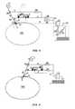
- Figure 3shows an embodiment of the remote centre of motion mechanism and adjustment positioner.
- Figure 4shows the adjustment of the remoter centre of rotation from O to O' by adjusting the position of the belt coupling and YZ table.
- Figure 5shows motion about the remote centre of motion provided by the apparatus of figure 4 after adjusting the remote centre of motion.
- Figure 6shows an alternative embodiment of an apparatus according to the present invention, wherein the second link is directly attached to the base link through a prismatic joint.
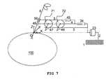
- Figure 7shows an alternative scheme of the mechanism for obtaining a 1:2 ratio displacement between two parallel translating links, based on one or more roller elements.
- an apparatusfor holding and manipulating an instrument about a predetermined remote centre of motion (rotation), which remains fixed during a given time period.
- the apparatushas a number of revolute and prismatic joints, rigid links and a constraint system to define the remote centre of motion.
- the remote centre of motion(rotation)can be additionally adjusted.
- the apparatuscan be either fixed on a frame 2, such as the bed frame, or on a mobile platform.
- the apparatuscan be divided into a RCM mechanism and an adjustment positioner.
- the RCM mechanismhas a base link preferably connected to a revolute joint the rotational axis of which coincides with the X-axis, which can revolve the whole RCM mechanism about the remote centre of rotation.
- the RCM mechanismwhich provides a second rotational degree of freedom has several rigid links and joints.
- Two parallel linksare connected by a prismatic joint.
- the first link of the parallel linksis connected to the distal end of the base link with another prismatic joint.
- the two prismatic jointsare also parallel in their motion.
- the two parallel linkshold the instrument holder via one revolute joint and one slide-revolute joint.
- the axial direction of the instrument holderwhich is inline from one joint to another, is intersecting with the remote centre of rotation.
- the parallel links, the instrument holder and base linkconstitute a plane and has a side intersecting with X-axis.
- the ratio of the distances between the remote centre of rotation to the first joint and the second joint on the instrument holderis equal to the displacement ratio of the two parallel links.
- a 1:2 displacement ratiois defined for the two parallel links via the constraint of the pulley system on it.
- the pulley systemis implemented on the first link of the parallel link.
- the second linkcouples one side of the belt.
- the base linkcouples to the other side. Therefore, when propelling the belt on the pulley system, the transmission induces the same displacement of second link and base link at opposite direction. This enables the two parallel links (first and second links) to achieve 1:2 displacements.
- the instrument holderis placed at the distal part of the parallel links and is connected to the parallel links with a revolute joint and a slide-revolute joint.
- the distance from the remote centre of rotation to the first joint on the instrument holderis equal to the distance from the first joint to the second joint of rotation.
- the motion of the instrument holderis constrained to a rotation about the Y-axis.
- the RCM mechanismphysically constraints the instrument holder to rotate about two orthogonal axes and provides the remote centre of motion along a fixed position in space. This point of remote centre of rotation is a fixed position with respect to the RCM mechanism, which means its location has already been defined when constructing the mechanism.
- an adjustment positionercan be added to move the position in space.
- the adjustment positioneris designed with a traditional two degrees of freedom YZ table which is placed underneath the revolute joint to move the remote centre of rotation to its designated position in Y- and Z-axis.
- an additional prismatic joint parallel to the parallel linksis inserted between the belt clamp connecting the base link to the pulley system.
- the prismatic joint on the RCM mechanismis also employed to perform adjustment in X-axis.
- the method in this embodimentpreserves the original stiffness of the RCM mechanism but equips it with demanded adjustment functions.
- Apparatuses according to the present inventioncan manipulate an instrument at a fixed rotation centre, which is physically defined by a RCM mechanism. Therefore, it can be used passively by opening/releasing the brakes or friction components and a user may manipulate the instrument in the instrument holder while the RCM mechanism constraints the point of rotation without the use of actuation. It can also be applied actively to implement motors and actuators on its links, joints and instrument holders to control the instrument to reach the desired position and orientation. It keeps the whole mechanism at a fixed distance to the patient which greatly reduces the risk of contacting the patient. It also minimizes the working space above the patient along its range of motion which allows co-manipulation with surgeons and multiple arms cooperation at the same time without colliding with each other.
- the apparatuspreferably further employs a technique which enables the adjustment of the remote centre of rotation by adjusting the position of the belt clamp rather than by adjusting the whole mechanism. Because the belt clamp is not a structure component, it can be design embedded onto the existing linkage which reduces the weight and cost and maintains the stiffness of the whole structure.
- Figure 1shows an embodiment of the remote centre of motion mechanism according to the invention in a typical application of MIS on a patient 100.
- a base link 3is connected to one side of the revolute joint 23.
- the rotational axis of joint 23is placed in line with the X-axis of the XYZ coordinate, which its origin O coincides with the small incision on the patient. It is also the remote centre of rotation for the surgical instrument that enters and is manipulated inside the body by levering on the point O.
- Revolute joint 23provides one degree of freedom of rotating along X-axis and is connected via a link 2 to a mounting fixture 1.
- a first link 4has three joints.
- the first link 4connects to the base link 3 with prismatic joint 34.
- the first link 4connects to the second link 5 with prismatic joint 45.
- the prismatic joint 34 and prismatic joint 45are parallel to X-axis and are intersecting with the instrument holder 6.
- the line between the two rotating axes of the pulleysis parallel to the direction of prismatic joint 34 and prismatic joint 45.
- a belt clamp 37On one side of the belt, a belt clamp 37 is fixed to the base link 3.
- belt clamp 57is fixed to the second link 5.
- the first link 4can have a linear displacement via the prismatic joint 34. It will also drive the belt to propel on pulley systems 7 due to the fixed belt clamp 37 and cause the second link 5 to slide via the prismatic joint 45. Thus, the displacement ratio of the prismatic joint 34 and prismatic joint 45 with respect to base link 3 will be 1:2 due to the constraint of the pulley system 7.
- the instrument holder 6is supported by the first link 4 with a revolute joint 46 and by the second link 5 with a slide-revolute joint 56.
- the revolute joint 46is nearer the remote centre of rotation compared to slide-revolute joint 56.
- the line connecting joint 46 and joint 56is intersecting with the remote centre of rotation.
- the distance between O to joint 46is equal to the distance between joint 46 and joint 56.
- a surgical instrument which is inline with the line connecting joint 46 and joint 56is held by the instrument holder and inserted into the small incision on the patient 100.
- the orientation of the surgical instrumentis steered by the revolute joint 23 to obtain its rotation around X-axis.
- the displacements of the joint 46 and joint 56which are the identical to the motion on the prismatic joint 34 and 45, will provide the surgical instrument to rotate around Y-axis.
- Figure 2shows the pulley system 7 constraints with the 1:2 ratio displacements on parallel links 4 and 5 to provide remote centre of motion around Y-axis.
- a surgical instrumentis held by the instrument holder 6 and inserted into the small incision O on patient 100.
- the distance L1is the vertical distance (in Z-direction) from point O to joint 46.
- the distance L2is the vertical distance from point O to joint 56.
- L1:L21:2 since the distance from point O to joint 46 is equal to joint 46 to joint 56.
- S1is the displacement along X-axis of the joint 46 with respect to base link 3 via the motion on prismatic joint 34.
- S2is the displacement along X-axis of joint 56 with respect to base link 3 via the motion on prismatic joint 45.
- FIG. 7shows the mechanism for obtaining a 1:2 ratio displacement between two parallel translating links.
- First link 4 and second link 5slide in linear bearing elements (prismatic joints) 34 and 45 respectively.
- roller elements 71 and 72are provided which are constrained to roll without slipping on rolling surfaces provided on second link 5 and base link 3 respectively. This constraint can be achieved by the use of high friction materials with preloading, by zero-backlash rack-and-pinion elements, or by any suitable means known in the state-of-the-art.
- First link 4is connected to the centre of the rolling elements 71 and 72 by revolute joint 47 and 48 respectively.
- the roller elements 71 and 72constraints the 1:2 ratio displacements on parallel links 4 and 5 to provide remote centre of motion on Y-axis.
- the two rolling elements 71 and 72can be replaced by a single rolling element if the linear bearing elements 34 and 45 take care of the parallelism between first link 4 and second link 5.
- Figure 3shows an embodiment of an adjustable remote centre of motion mechanism.
- the RCM mechanism of figure 1is connected to one side of the revolute joint 23 whose rotational axis is in line with the X-axis.
- An adjustment positioneris composed by an YZ table 20 and an additional prismatic joint 38 between the belt clamp 37 and base link 3.
- the YZ table 20is connected to the other side of the revolute joint 23 and comprises a prismatic joint 29 for moving the whole RCM mechanism in Z direction and a prismatic joint 19 for moving the whole RCM mechanism, the connecting link 2, link 9 and prismatic joint 29 along Y direction.
- the remote centre of rotation Ocan be adjusted via the YZ table 20.
- An additional prismatic joint 38is provided on the base link, and which divides the base link into a link 31 connected to the mounting fixture 1 (through revolute joint 23 and YZ table 20) and a link 8 connected to the belt clamp 37.
- the prismatic joint 38is parallel to joint 34 and connects link 31 and link 8.
- An adjustment of the remote centre of rotation O in X-directionis achieved by simultaneous and equivalent movement in prismatic joint 34 and prismatic joint 38.
- the motion of the instrument holder 6 around the remote centre of motion Ocan be still performed by fixing the motion on prismatic joint 38 and actuating the pulley system 7 to cause translational motion in joint 34 and joint 45. Since the belt clamp 37 only receives the load exerted on belt and does not support the whole RCM mechanism above it, the added prismatic joint 38 can be made small depending on the load on the belt clamp 37.
- the base link 31is still the main component for the structure stiffness. This arrangement makes use of the prismatic joint 34 to not only provides remote centre motion together with prismatic joint 45 but also to give an added function to adjust the remote centre of rotation O together with prismatic joint 38.
- Figure 4shows the adjustment of the remoter centre of rotation from O to O' by adjusting the position of the belt clamp 37 and YZ table.
- a surgical instrumentis held by instrument holder 6 and is supported by the RCM mechanism on one side of the revolute joint 23.
- the remote centre of rotationwill be shifted from point O to point O'.
- the YZ table connected to the other side of the revolute joint 23makes the adjustment of its respective Y and Z directions.
- the prismatic joint 34 and prismatic joint 38move together while the prismatic joint 45 keeps static to perform the adjustment of the remote centre of rotation in X-direction.
- the pulley system 7is not propelled during the adjustment period.
- RCMis enabled when the prismatic joint 38 is fixed.
- the orientation of the surgical instrumentis steered by the revolute joint 23 to obtain its rotation around X-axis.
- the displacements of the joint 46 and joint 56which are identical to the motion on the prismatic joint 34 and 45 while the prismatic joint 38 keeps static, will provide the surgical instrument to rotate around Y-axis.
- Figure 5shows the remote centre of motion provided by the embodiment of figure 4 after adjusting the remote centre of rotation.
- the YZ table and the prismatic joint 38keep static which enables the pulley system 7 to perform its 1:2 displacement constraints to joint 46 and joint 56.
- the instrument holder 6always points toward the vertex O' of the triangles, which are formed by the span of instrument holder 6 and the trajectories of the joint 46 and joint 56.
- Figure 6shows an alternative embodiment to the apparatus of figure 1 .
- the second link 5is connected to the base link 3 with the prismatic joint 35.
- the advantage of this alternativeis the even distribution of the load on the prismatic joint 34 and 35.
- the drawbackis that the stroke of prismatic joint 35 is twice the stroke of prismatic joint 34, whereas in the embodiment of figure 1 , the prismatic joint 34 and 45 have the same stroke since the second link is connect to the first link.
Landscapes
- Health & Medical Sciences (AREA)
- Surgery (AREA)
- Engineering & Computer Science (AREA)
- Life Sciences & Earth Sciences (AREA)
- Medical Informatics (AREA)
- Robotics (AREA)
- Biomedical Technology (AREA)
- Heart & Thoracic Surgery (AREA)
- Nuclear Medicine, Radiotherapy & Molecular Imaging (AREA)
- Molecular Biology (AREA)
- Animal Behavior & Ethology (AREA)
- General Health & Medical Sciences (AREA)
- Public Health (AREA)
- Veterinary Medicine (AREA)
- Manipulator (AREA)
- Transmission Devices (AREA)
Description
- This invention is related to the field of robotics, in particular to robot assisted surgery.
- The present invention is directed to a remote centre of motion positioner used to support an instrument and provide a motion with fixed centre of rotation in a designated position where no physical object is present. It is very useful in performing robot assisted Minimally Invasive Surgery (MIS) to allow steering the surgical instrument inside a patient's body through a small incision on the patient's body.
- In MIS procedure, a few small incisions (dia. 10 mm) are opened on a patient to allow instruments to be inserted therein. In one of the incisions, a laparoscope acquires the images inside the surgical site and shows it on a TV screen. Several other MIS instruments such as graspers, scissors, scalpel, and needle holders are inserted into the rest incisions. In order to be able to work through the small incision, these MIS instruments are often thin and long with at one end tools working in the surgical field and at the other end handles manipulated by a surgeon. The MIS techniques are different and more difficult compared with traditional open surgery. First of all, from a dexterity point of view, the motion of the surgeon's hand is constrained from 6 degrees of freedom (DOF) to 4 DOF. In addition to that, the small incision can be considered as the fulcrum of a lever. The scaling of the motion is not easy to be predicted by a novice surgeon. Secondly, the vision perception is degraded from 3 dimensions to 2 dimensions due to the imaging system. Therefore, to perform MIS surgical techniques a surgeon is demanded for additional training and practice in a limited number of simple procedures only.
- Although the imposed difficulty troubles the surgeon, patients are taking much more advantages from the MIS procedures. Small incision means fewer traumas, faster recovery and less risk.
- A robotic system (daVinci® surgical system of Intuitive Surgical, Inc.) has been developed to assist surgeons in performing MIS procedure. Equipped with 3D vision and additional 4 DOF Endowrist®, it successfully restores the lost dexterity and the missing visual perception. It is until now the most successful MIS robotic system in technology and in business outcome.
- The daVinci® surgical system can be further divided into four components: the Remote Centre of Motion (RCM) Arm; the manipulator positioning linkage; the exchangeable surgical instruments (3D laparoscope and Endowrist®) and the surgeon console. The RCM arm employs the famous double-parallelogram mechanism or similar to provide the remote centre of motion where the centre of rotation is physically constrained (
US 7108688 ,US 7021173 ,US 5397323 ,US 6702805 ). It decouples the two orthogonal rotational axes at the remote centre of motion, which can be directly controlled without the need of programming and complex inverse kinematics. The RCM arm allows the MIS instrument to be manipulated through the small incision with minimal stretching of the soft tissues. However, in order to obtain sufficient range of motion and stiffness, the resulting RCM arm employs a huge amount of working space above the patient. When two or more RCM arms cooperate to perform robotic MIS procedure, there is a great chance to hit the surgeon next to it or two arms will collide with each other during the manipulation. In addition, the physically fixed rotation centre requires additional manipulator positioning linkage (US 6246200 ,US 5824007 ) to align fixed remote centre to the small incision on the patient. It increases the cost and occupies significant space along the bedside. This prevents the surgeon to stay near the patient and to force him to perform his task on a surgeon's console which is located at a distance from the patient. InUS 7108688 andUS 5397323 , a method to adjust the rotation point by adjusting the length of the linkages is proposed. However, the double-parallelogram mechanism will hang above the patient with only its one end supported by a revolute joint. This method will significantly reduce the stiffness and accuracy on the instrument holder and increases the size and weight of the whole arm. WO 01/34017 claim 1 and describes a remote centre of revolute motion manipulator, including first and second parallelogram linkage mechanisms, each one including a link pivotally mounted to a base for rotation about respective first and second axes to move in two parallel planes. The first and second parallelogram linkages are connected together by parallel connector links. The manipulator further includes a tool holder pivotally connected to the parallel connector links.- Another mechanism which also provides a remote centre of motion is described in
US 5766126 and uses cross goniometric axes. The principal difficulty lies in the optimal choices between its size, payload, accuracy, and working radius. The patent derived manipulator Endoassist (Prosurgics Ltd, UK) employs a big structure to obtain sufficient range of motion. It occupies a bedside space and also a certain amount of working space above the patient. Not to mention the demand of high quality goniometric axes. Smaller manipulator examples like FIPS (Prototype of KARL STORZ GmbH & Co. KG, Germany), ViKY(Endocontrol Inc, France) and Freehand (Prosurgics Ltd, UK) are using small size goniometric axes. However, due to the mounting of the actuators and its mechanisms in the small area, their payload and range of motion are relatively small. On both big and small manipulators, due to their fixed remote centre of rotation, the adjustment of the remote centre point is obtained either by a mobile platform on the floor or a flexible arm (e.g. Fisso articulated arm, Baitella AG, Switzerland) coupled to the bed frame, which further increases the cost or decreases the stiffness. - In
US 6723106 , a surgical manipulator is disclosed which employs a mechanism including two parallel arms pivotably supporting a medical tool with the orientation of the medical tool being adjusted by varying the position of joints. In order to achieve multiple degrees of freedom and adjust the remote centre of rotation via these two parallel arms, additional degrees of freedom are implemented, which couple the two orthogonal rotational axes at the remote centre of motion. The mechanism is not a passive remote centre of motion mechanism like the double parallelogram mechanism which means it requires dedicated programming and controller to execute its remote centre of motion. - In "A New, Compact MR-Compatible Surgical Manipulator for Minimally Invasive Liver Surgery", Medical Image Computing and Computer-Assisted Intervention - MICCAI 2002, pp. 99-106, Kimet al. disclose in
Fig. 2 andFig. 3 a remote centre of motion surgical manipulator comprising two parallel linkages pivotably connected to a gripper at fixed distances from the remote centre of motion. The two linkages are made to move linearly with fixed ratio so that the gripper is made to rotate about the remote centre of motion. The parallel linkages are driven by two ball screws. The two ball screws are coupled to a same motor through different gear transmission ratios, which provides for the fixed ratio linear motion of the parallel linkages. - In the latter RCM manipulator, the driving mechanism has a length equal to the total displacement of the linkages, which leads to a bulky arrangement and can lead to a lowered stiffness. Furthermore, the location of the remote centre of motion is only adjustable by using an adjustable mounting fixture which further affects the stiffness of the manipulator. The same drawbacks also apply as described above.
- It is an aim of the present invention to provide an apparatus for generating motion around a remote centre of motion which makes it possible to solve the problems of the state of the art. In particular, it is an aim of the present invention to provide an apparatus having a remote centre of motion, which is more compact and has an increased stiffness compared to the RCM apparatuses of the prior art.
- The invention provides for an apparatus, as set out in the appended claims, for generating motion around a remote centre of (rotary) motion, such as a manipulator or robot arm. The apparatus comprises a member arranged to revolve about the remote centre of motion, a base link coupled to a mounting fixture, and a first link and a second link arranged at a distance from each other. The first and second links are translatable relative to the base link, relative to each other and parallel to each other along a first direction, such that translational displacement of the first link relative to the base link and of the second link relative to the base link along the first direction occurs at a fixed ratio of displacement. The fixed ratio of displacement is such that the translational displacement of the first link is smaller than the translational displacement of the second link. The first link and the second link are pivotably coupled to the member at respective distances from the remote centre of motion, such that the ratio of said respective distances equals said fixed ratio of displacement. This constraint enables the member to revolve about the remote centre of motion.
- According to the invention, the apparatus comprises means for generating (relative) translational motion of a first element and of a second element along parallel but opposite directions. Hence, said translational motion is such that the sense of (relative) displacement of the first element is opposite to the sense of (relative) displacement of the second element. The means for generating translational motion is provided on (or fixedly connected to) the first link and is so arranged (aligned) as to provide motion parallel to the first direction. By fixating the base link and providing the first element to be fixedly connectable to the base link and the second element to be fixedly connectable to the second link, it is obtained that generation of said translational motion of the first element and of the second element enables the first link and the second link to translate relative to the base link with said fixed ratio of displacement.
- The present invention therefore proposes an alternative solution to the driving system of the linkage mechanism providing for a remote centre of motion. According to the invention, means are provided for generating two linear motions which are parallel, but of opposite sense. This means is provided on the movable link that has the smaller displacement. Hence, the motion generating means translates together with the first link. By fixing one linear motion to the fixed link (base link) and the other one to the movable link having the larger displacement, a driving mechanism is obtained that has a resemblance to a cascade system, in which the movable links can be displaced according to a predetermined ratio of displacement, relative to the base link.
- An advantage of such a system is that the stroke of the driving mechanism need only be a fraction of the largest displacement achieved by the driven linkages. It follows that both a more compact, and stiffer manipulator can be obtained, which at the same time is easier and less costly to manufacture.
- Preferably, the means for generating translational motion of the first element and of the second element is arranged to generate equal but opposite displacement of the first and second elements, such that the fixed ratio of displacement is 1:2. Such an assembly leads to the most simple implementation of the driving mechanism according to the present disclosure.
- Preferably, the base link extends between the mounting fixture and the first element over a length which is adjustable along the first direction, which allows to adjust the location of the remote centre of motion along the first direction. An advantage of having the "cascade" driving system according to the present disclosure, is that the initial adjustment of the remote centre of motion along the first direction (direction of motion of the first and second links) is very simple to implement. It suffices namely to make the base link adjustable in length. Since the linkage mechanism formed by the first and second links and by the member are mounted on the base link, the stiffness of the system is not affected. Conversely, in the prior art RCM systems, making the remote centre of motion adjustable along the direction of motion of the manipulator arms always causes a stiffness decrease. More preferably, the adjustable length of the base link is obtained by providing a linear sliding element (a prismatic joint) dividing the base link in a first part that is connected to the mounting fixture and in a second part that is connected to the first element. Advantageously, the point of connection between the base link and the first link is provided on the first part. This allows to maintain the stiffness of the RCM arm, while providing for adjustment of the remote centre of motion along the first direction.
- Preferably, the base link is coupled to the mounting fixture through a revolute joint having an axis of rotation parallel to the first parallel directions and comprising the remote centre of motion. As a result, an additional rotational DOF can be implemented for the member around the remote centre of motion.
- Preferably, the means for generating translational motion comprises a pulley and belt mechanism, which is provided on the first link. The first and the second elements are provided on the belt. Alternatively, the means for generating translational motion comprises a roller element arranged to roll over two oppositely arranged rolling surfaces. The rolling surfaces form the first and the second elements. A preferred embodiment employs a pinion as roller element and a couple of racks a roller surfaces.
- Preferably, the apparatus comprises a first linear sliding element (prismatic joint) between the base link and the first link and a second linear sliding element (prismatic joint) between the first link and the second link. The second link is hence coupled to the base link through the first link. Alternatively, the apparatus comprises a first linear sliding element between the base link and the first link and a second linear sliding element directly connected to the base link and to the second link. The linear sliding elements can act as bearing elements.
- Preferably, the first link and the second link are coupled to the member by a revolute joint and a slide-revolute joint.
- Preferably, the member is arranged as an instrument holder.
- According to an aspect of the disclosure, an apparatus is provided comprising the following elements:
- a base link;
- a first and a second link whereby the first link is connected to the base link by a first prismatic joint, and the second link is connected to the first link by a second prismatic joint, and whereby the movement axes of the first prismatic joint and the second prismatic joint are parallel;
- an instrument holder supported by the first link with a revolute joint and by the second link with a slide-revolute joint; whereby the line between the revolute joint and the slide-revolute joint is intersecting with the movement axes of the first prismatic joint and the second prismatic joint and whereby the remote centre of motion is on said line and the revolute joint is proximal to the remote centre of motion while the slide-revolute joint is distal to the remote centre of motion; and
- a system for arranging a fixed displacement ratio between the second prismatic joint and the first prismatic joint whereby the displacement ratio is equal to the ratio between the distance between the remote centre of motion and the slide revolute joint and the distance between the remote centre of motion and the revolute joint.
- An alternative embodiment is that the revolute joint is replaced by a slide-revolute joint and that the slide-revolute joint is replaced by a revolute joint. A sliding function should be implemented on at least one of the joints between the instrument holder and the first and second links.
- In a preferred embodiment the system for arranging the fixed displacement ratio between the second prismatic joint and the first prismatic joint is a pulley system. In another preferred embodiment the displacement ratio is 1:2 and the pulley system comprises two pulleys (or sprockets) and a closed timing belt for circulating the pulleys whereby the pulley system is attached to the first link and whereby the line between the two rotational axes of the pulleys is parallel to the movement axis of the first prismatic joint and whereby one side of the closed timing belt is coupled to the base link and the other side of the belt is coupled to the second link. The closed timing belt can alternatively be a belt, wire, chain or cable or the like. The pulleys on the pulley system can alternatively be sprockets or similar devices with the same functionality.
- In a preferred embodiment the apparatus of the present disclosure further comprises an additional link to the base link. Said additional link is connected to the base link by a third prismatic joint and is connected to the system for providing a fixed displacement ratio between the second prismatic joint and the first prismatic joint whereby the movement axis of the third prismatic joint is parallel to the movement axis of the first prismatic joint which allows for moving (adjusting) the remote centre of motion in the direction of the movement axes of the third prismatic joint and the first prismatic joint.
- In yet another preferred embodiment the system for providing a fixed displacement ratio between the second prismatic joint and the first prismatic joint is a pulley system comprising two pulleys and the additional link is connected to the closed timing belt of the pulley system whereby the movement axis of the third prismatic joint is parallel to the movement axis of the first prismatic joint which allows for moving (adjusting) the remote centre of motion in the direction of the movement axes of the third prismatic joint and the first prismatic joint. Hereby, the adjustment of the remote centre of rotation in the direction of the movement axes of first and third prismatic joints is achieved by simultaneous and equivalent movement in said prismatic joints. The remote centre of motion can still be performed by fixing the motion on the third prismatic joint and is achieved by the pulley system and the first prismatic joint and the second prismatic joint.
- In one embodiment, the apparatus of the present disclosure further comprises a third revolute joint connected to the base link for rotating the apparatus around an axis which is parallel to the first prismatic joint and intersects the remote centre of motion.
- In another preferred embodiment the apparatus of the present disclosure further comprises an adjustment positioner for moving the apparatus in a plane which is perpendicular to the axis of the third revolute joint.
- According to another aspect of the disclosure, an apparatus is provided comprising the following elements:
- a base link;
- a first and a second link whereby the first link is connected to the base link by a first prismatic joint, and the second link is connected to the first link by a second prismatic joint, and whereby the movement axes of the first prismatic joint and the second prismatic joint are parallel;
- an instrument holder supported by the first link with a revolute joint and by the second link with a slide-revolute joint (hereby the revolute joint can as well be a slide-revolute joint while the slide revolute joint is a revolute joint) ; whereby the line between the revolute joint and the slide-revolute joint is intersecting with the movement axes of the first prismatic joint and the second prismatic joint and whereby the remote centre of motion is on said line and the revolute joint is proximal to the remote centre of motion while the slide-revolute joint is distal thereto;
- a pulley system for arranging a fixed displacement ratio between the second prismatic joint and the first prismatic joint whereby the displacement ratio is equal to the ratio between the distance between the remote centre of motion and the slide revolute joint and the distance between the remote centre of motion and the revolute joint. The pulley system comprises two pulleys and a closed timing belt for circulating the pulleys whereby the pulley system is attached to the first link and whereby the line between the two rotational axes of the pulleys is parallel to the movement axis of the first prismatic joint;
- an additional link, said additional link connected to the base link by a third prismatic joint and said additional link coupled to one side of the closed timing belt of the pulley system, whereby the movement axis of the third prismatic joint is parallel to the movement axis of the first prismatic joint which allows for moving the remote centre of motion in the direction of the movement axes of the third prismatic joint and the second prismatic joint. Hereby the other side of the closed timing belt of the pulley system is coupled to the second link.
- The adjustment of the remote centre of rotation in the direction of the movement axes of the first and third prismatic joints in the apparatus described above is achieved by simultaneous and equivalent movement in the first prismatic joint and the third prismatic joint. The remote centre of motion is performed by fixing the motion on the third prismatic joint and is achieved by the pulley system and the first prismatic joint and the second prismatic joint. In a preferred embodiment the displacement ratio is equal to 1:2 and when the third prismatic joint is fixed, a displacement of the first prismatic joint causes through the constraints on the pulley system a twice as large displacement of the second prismatic joint thereby producing the remote centre of revolute motion (since the distance between the centre of motion and the revolute joint is half of the distance between the centre of motion and the slide-revolute joint).
- In one embodiment the apparatus of the present disclosure can further comprise a third revolute joint connected to the base link for rotating the apparatus around an axis which is parallel to the first prismatic joint and intersects the remote centre of motion.
- In another preferred embodiment the apparatus of the present disclosure can further comprise an adjustment positioner for moving the apparatus in a plane which is perpendicular to the axis of the third revolute joint.
Figure 1 shows an embodiment of the remote centre of motion mechanism.Figure 2 shows the system offigure 1 wherein the instrument holder is rotated around the remote centre of motion. The constraints for a 1:2 ratio displacements on parallel links to provide the remote centre of motion in Y-axis is represented as well.Figure 3 shows an embodiment of the remote centre of motion mechanism and adjustment positioner.Figure 4 shows the adjustment of the remoter centre of rotation from O to O' by adjusting the position of the belt coupling and YZ table.Figure 5 shows motion about the remote centre of motion provided by the apparatus offigure 4 after adjusting the remote centre of motion.Figure 6 shows an alternative embodiment of an apparatus according to the present invention, wherein the second link is directly attached to the base link through a prismatic joint.Figure 7 shows an alternative scheme of the mechanism for obtaining a 1:2 ratio displacement between two parallel translating links, based on one or more roller elements.- Definitions:
- A "revolute joint" is a one degree of freedom kinematic pair which provides single axis rotation function.
- A "prismatic joint" is a one degree of freedom kinematic pair which provides single axis linear motion capability.
- "Movement axis of prismatic joint" is the line which coincides with the occurred motion of the kinematic pair of the prismatic joint
- A "slide-revolute joint" is a two degrees of freedom joint which provides one degree of freedom rotation function along an axis of linear motion (one degree of freedom translation).
- A "rigid link or link" is a solid object which connects with another rigid link via related joints to obtain relative motion.
- A "belt clamp" is a physical fixation between the related link to the belt.
- In a broad aspect an apparatus is provided for holding and manipulating an instrument about a predetermined remote centre of motion (rotation), which remains fixed during a given time period.
- An exemplifying embodiment of an apparatus according to the present invention is described in what follows, with reference to
figure 1 . The apparatus has a number of revolute and prismatic joints, rigid links and a constraint system to define the remote centre of motion. Preferably, the remote centre of motion(rotation) can be additionally adjusted. The apparatus can be either fixed on aframe 2, such as the bed frame, or on a mobile platform. The apparatus can be divided into a RCM mechanism and an adjustment positioner. The RCM mechanism has a base link preferably connected to a revolute joint the rotational axis of which coincides with the X-axis, which can revolve the whole RCM mechanism about the remote centre of rotation. This is a first rotational degree of freedom for the demanded remote centre of motion, but not the main one. The RCM mechanism, which provides a second rotational degree of freedom has several rigid links and joints. Two parallel links are connected by a prismatic joint. The first link of the parallel links is connected to the distal end of the base link with another prismatic joint. The two prismatic joints are also parallel in their motion. The two parallel links hold the instrument holder via one revolute joint and one slide-revolute joint. The axial direction of the instrument holder, which is inline from one joint to another, is intersecting with the remote centre of rotation. The parallel links, the instrument holder and base link constitute a plane and has a side intersecting with X-axis. This plane will rotate along the X-axis when rotating the revolute joint. To achieve the second degree of freedom, the ratio of the distances between the remote centre of rotation to the first joint and the second joint on the instrument holder is equal to the displacement ratio of the two parallel links. In this embodiment, a 1:2 displacement ratio is defined for the two parallel links via the constraint of the pulley system on it. The pulley system is implemented on the first link of the parallel link. The second link couples one side of the belt. The base link couples to the other side. Therefore, when propelling the belt on the pulley system, the transmission induces the same displacement of second link and base link at opposite direction. This enables the two parallel links (first and second links) to achieve 1:2 displacements. Thus, the instrument holder is placed at the distal part of the parallel links and is connected to the parallel links with a revolute joint and a slide-revolute joint. In this embodiment the distance from the remote centre of rotation to the first joint on the instrument holder is equal to the distance from the first joint to the second joint of rotation. Thus, the motion of the instrument holder is constrained to a rotation about the Y-axis. In this embodiment, the RCM mechanism physically constraints the instrument holder to rotate about two orthogonal axes and provides the remote centre of motion along a fixed position in space. This point of remote centre of rotation is a fixed position with respect to the RCM mechanism, which means its location has already been defined when constructing the mechanism. - To move the remote centre of rotation, which can be desired when implemented in the operating theatre, an adjustment positioner can be added to move the position in space. The adjustment positioner is designed with a traditional two degrees of freedom YZ table which is placed underneath the revolute joint to move the remote centre of rotation to its designated position in Y- and Z-axis.
- To move the point along X-axis, an additional prismatic joint parallel to the parallel links is inserted between the belt clamp connecting the base link to the pulley system. In this way, the prismatic joint on the RCM mechanism is also employed to perform adjustment in X-axis. Unlike the traditional way of an additional link and prismatic joint which has to support and move the whole mechanism in X axis, the method in this embodiment preserves the original stiffness of the RCM mechanism but equips it with demanded adjustment functions.
- Apparatuses according to the present invention can manipulate an instrument at a fixed rotation centre, which is physically defined by a RCM mechanism. Therefore, it can be used passively by opening/releasing the brakes or friction components and a user may manipulate the instrument in the instrument holder while the RCM mechanism constraints the point of rotation without the use of actuation. It can also be applied actively to implement motors and actuators on its links, joints and instrument holders to control the instrument to reach the desired position and orientation. It keeps the whole mechanism at a fixed distance to the patient which greatly reduces the risk of contacting the patient. It also minimizes the working space above the patient along its range of motion which allows co-manipulation with surgeons and multiple arms cooperation at the same time without colliding with each other.
- The apparatus preferably further employs a technique which enables the adjustment of the remote centre of rotation by adjusting the position of the belt clamp rather than by adjusting the whole mechanism. Because the belt clamp is not a structure component, it can be design embedded onto the existing linkage which reduces the weight and cost and maintains the stiffness of the whole structure.
Figure 1 shows an embodiment of the remote centre of motion mechanism according to the invention in a typical application of MIS on apatient 100. Abase link 3 is connected to one side of the revolute joint 23. The rotational axis of joint 23 is placed in line with the X-axis of the XYZ coordinate, which its origin O coincides with the small incision on the patient. It is also the remote centre of rotation for the surgical instrument that enters and is manipulated inside the body by levering on the point O. Revolute joint 23 provides one degree of freedom of rotating along X-axis and is connected via alink 2 to a mountingfixture 1.- A
first link 4 has three joints. Thefirst link 4 connects to thebase link 3 with prismatic joint 34. Thefirst link 4 connects to thesecond link 5 with prismatic joint 45. The prismatic joint 34 and prismatic joint 45 are parallel to X-axis and are intersecting with theinstrument holder 6. Apulley system 7, which is composed by two pulleys and a closed timing belt or cable or wire circulating the pulleys, is attached on thefirst link 4. The line between the two rotating axes of the pulleys is parallel to the direction of prismatic joint 34 and prismatic joint 45. On one side of the belt, abelt clamp 37 is fixed to thebase link 3. On the other side,belt clamp 57 is fixed to thesecond link 5. Since the pulleys are freely rotating each around its axis, thefirst link 4 can have a linear displacement via the prismatic joint 34. It will also drive the belt to propel onpulley systems 7 due to the fixedbelt clamp 37 and cause thesecond link 5 to slide via the prismatic joint 45. Thus, the displacement ratio of the prismatic joint 34 and prismatic joint 45 with respect tobase link 3 will be 1:2 due to the constraint of thepulley system 7. Theinstrument holder 6 is supported by thefirst link 4 with a revolute joint 46 and by thesecond link 5 with a slide-revolute joint 56. The revolute joint 46 is nearer the remote centre of rotation compared to slide-revolute joint 56. The line connecting joint 46 and joint 56 is intersecting with the remote centre of rotation. The distance between O to joint 46 is equal to the distance between joint 46 and joint 56. A surgical instrument which is inline with the line connecting joint 46 and joint 56 is held by the instrument holder and inserted into the small incision on thepatient 100. Thus, the orientation of the surgical instrument is steered by the revolute joint 23 to obtain its rotation around X-axis. The displacements of the joint 46 and joint 56, which are the identical to the motion on the prismatic joint 34 and 45, will provide the surgical instrument to rotate around Y-axis. Figure 2 shows thepulley system 7 constraints with the 1:2 ratio displacements onparallel links instrument holder 6 and inserted into the small incision O onpatient 100. The distance L1 is the vertical distance (in Z-direction) from point O to joint 46. The distance L2 is the vertical distance from point O to joint 56. Thus, L1:L2 = 1:2 since the distance from point O to joint 46 is equal to joint 46 to joint 56. S1 is the displacement along X-axis of the joint 46 with respect tobase link 3 via the motion on prismatic joint 34. S2 is the displacement along X-axis of joint 56 with respect tobase link 3 via the motion on prismatic joint 45. Due to the variable distance between joint 45 and joint 56 with respect to their motions, a sliding function is implemented on joint 56. An alternative is to put the sliding function on joint 46. Since thepulley system 7 is connected viabelt clamp 37 to thebase link 3 and viabelt clamp 57 to thesecond link 5, S1 and S2 have a fixed ratio of 1:2. Therefore, theinstrument holder 6 always points toward the vertex O of the triangles, which are formed by the span of surgical instrument and the trajectories of the joint 46 and joint 56. By appropriate selecting the distance L1 and the demanded range of rotation in Y-axis, the remote centre of motion can provide a minimum profile of its working space above the patient and keep the RCM mechanism at a constant distance (L1) to the patient. This is advantageous compared to the remote centre of motion generated by a double parallelogram mechanism, wherein the rotation about the remote centre of motion (on Y-axis) is the result of the two coupled parallelograms manipulating the instrument holder above the patient. The distance to the patient and the working space above the patient are varying based on the angle of the instrument holder. This increases the possibility of colliding with the patient and also with other robot arms.- The pulley and belt system described above, can be replaced by one or more roller elements as shown in
figure 7. Figure 7 shows the mechanism for obtaining a 1:2 ratio displacement between two parallel translating links.First link 4 andsecond link 5 slide in linear bearing elements (prismatic joints) 34 and 45 respectively. Between thesecond link 5 and thebase link 3roller elements second link 5 andbase link 3 respectively. This constraint can be achieved by the use of high friction materials with preloading, by zero-backlash rack-and-pinion elements, or by any suitable means known in the state-of-the-art.First link 4 is connected to the centre of the rollingelements roller elements parallel links - The two
rolling elements linear bearing elements first link 4 andsecond link 5. Figure 3 shows an embodiment of an adjustable remote centre of motion mechanism. The RCM mechanism offigure 1 is connected to one side of the revolute joint 23 whose rotational axis is in line with the X-axis. An adjustment positioner is composed by an YZ table 20 and an additional prismatic joint 38 between thebelt clamp 37 andbase link 3. The YZ table 20 is connected to the other side of the revolute joint 23 and comprises a prismatic joint 29 for moving the whole RCM mechanism in Z direction and a prismatic joint 19 for moving the whole RCM mechanism, the connectinglink 2, link 9 and prismatic joint 29 along Y direction. The remote centre of rotation O can be adjusted via the YZ table 20.- As a general rule the more adjustment degrees of freedom are implemented, the heavier and stronger the adjustment devices need to be in order to preserve the stiffness of the system. According to an aspect of the present invention, a different approach is implemented for adjusting the remote centre of rotation O in X-direction, which avoids the above problems. An additional prismatic joint 38 is provided on the base link, and which divides the base link into a
link 31 connected to the mounting fixture 1 (through revolute joint 23 and YZ table 20) and alink 8 connected to thebelt clamp 37. The prismatic joint 38 is parallel to joint 34 and connectslink 31 andlink 8. With this kind of arrangement,link 4, link 8 andlink 5 can have relative movement againstlink 31 in X-direction. An adjustment of the remote centre of rotation O in X-direction is achieved by simultaneous and equivalent movement in prismatic joint 34 and prismatic joint 38. The motion of theinstrument holder 6 around the remote centre of motion O can be still performed by fixing the motion on prismatic joint 38 and actuating thepulley system 7 to cause translational motion in joint 34 and joint 45. Since thebelt clamp 37 only receives the load exerted on belt and does not support the whole RCM mechanism above it, the added prismatic joint 38 can be made small depending on the load on thebelt clamp 37. Thebase link 31 is still the main component for the structure stiffness. This arrangement makes use of the prismatic joint 34 to not only provides remote centre motion together with prismatic joint 45 but also to give an added function to adjust the remote centre of rotation O together with prismatic joint 38. Figure 4 shows the adjustment of the remoter centre of rotation from O to O' by adjusting the position of thebelt clamp 37 and YZ table. A surgical instrument is held byinstrument holder 6 and is supported by the RCM mechanism on one side of the revolute joint 23. The remote centre of rotation will be shifted from point O to point O'. Thus, the YZ table connected to the other side of the revolute joint 23 makes the adjustment of its respective Y and Z directions. The prismatic joint 34 and prismatic joint 38 move together while the prismatic joint 45 keeps static to perform the adjustment of the remote centre of rotation in X-direction. Thepulley system 7 is not propelled during the adjustment period. When the adjustment is completed, RCM is enabled when the prismatic joint 38 is fixed. The orientation of the surgical instrument is steered by the revolute joint 23 to obtain its rotation around X-axis. The displacements of the joint 46 and joint 56, which are identical to the motion on the prismatic joint 34 and 45 while the prismatic joint 38 keeps static, will provide the surgical instrument to rotate around Y-axis.Figure 5 shows the remote centre of motion provided by the embodiment offigure 4 after adjusting the remote centre of rotation. The YZ table and the prismatic joint 38 keep static which enables thepulley system 7 to perform its 1:2 displacement constraints to joint 46 and joint 56. Theinstrument holder 6 always points toward the vertex O' of the triangles, which are formed by the span ofinstrument holder 6 and the trajectories of the joint 46 and joint 56.Figure 6 shows an alternative embodiment to the apparatus offigure 1 . Thesecond link 5 is connected to thebase link 3 with the prismatic joint 35. The advantage of this alternative is the even distribution of the load on the prismatic joint 34 and 35. However, the drawback is that the stroke of prismatic joint 35 is twice the stroke of prismatic joint 34, whereas in the embodiment offigure 1 , the prismatic joint 34 and 45 have the same stroke since the second link is connect to the first link.
Claims (13)
- Apparatus for generating motion around a remote centre of rotary motion (O), comprising:- a member (6) arranged to revolve about the remote centre of motion (O),- a base link (3, 8, 31) adapted to be coupled to a mounting fixture (1), and- a first link (4) and a second link (5) arranged at a distance from each other and translatable relative to the base link (3, 8, 31), relative to each other and parallel to each other along a first direction, such that translational displacement of the first link (4) relative to the base link (3, 8, 31) and of the second link (5) relative to the base link (3, 8, 31) along the first direction occurs at a fixed ratio of displacement, said translational displacement of the first link (4) being smaller than said translational displacement of the second link (5),wherein the first link (4) and the second link (5) are pivotably coupled to the member (6) at respective distances (L1, L2) from the remote centre of motion (O), such that the ratio of said respective distances equals said fixed ratio of displacement, enabling the member (6) to revolve about the remote centre of motion,
wherein the apparatus comprises means (7, 71, 72) for generating translational motion of a first element (37) and of a second element (57) along parallel but opposite directions, wherein the means for generating translational motion is arranged to translate together with the first link (4) and is arranged to provide motion parallel to the first direction and wherein, in use, the base link is fixed in a position, the first element (37) is fixedly connected to the base link (3, 8, 31) and the second element (57) is fixedly connected to the second link (5), such that generation of said translational motion of the first element (37) and of the second element (57) enables the first link (4) and the second link (5) to translate relative to the base link (3, 8, 31) with said fixed ratio of displacement,
characterised in that the first link (4) and the second link (5) are adapted to translate relative to the base link (3, 8, 31) by linear displacement to obtain the fixed ratio of displacement. - Apparatus of claim 1, wherein the means (7, 71, 72) for generating translational motion of the first element (37) and of the second element (57) is arranged to generate equal but opposite displacement of the first and second elements, such that said fixed ratio of displacement is 1:2.
- Apparatus of any one preceding claim, wherein the base link (31, 8) has an adjustable length between the mounting fixture (1) and the first element (37) so as to adjust the location of the remote centre of motion (O).
- Apparatus of claim 3, wherein the base link comprises a linear sliding element (38) dividing the base link in a first part (31) adapted to be coupled to the mounting fixture (1) and a second part (8) connected to the first element (37) for making the length of the base link adjustable along the first direction and wherein the first part (31) connects the base link and the first link (4).
- Apparatus of any one preceding claim, wherein the base link (3, 8, 31) is adapted to be coupled to the mounting fixture (1) through a revolute joint (23) having an axis of rotation parallel to the first parallel directions and comprising the remote centre of motion (O).
- Apparatus of any one preceding claim, wherein the means for generating translational motion comprises a pulley and belt mechanism (7).
- Apparatus of any one claim 1 to 5, wherein the means for generating translational motion comprises a roller element (71, 72) arranged to roll over two oppositely arranged rolling surfaces forming the first and the second elements.
- Apparatus of claim 7, wherein the roller element is a pinion and the rolling surfaces are racks.
- Apparatus of any one preceding claim, comprising a first linear sliding element (34) between the base link (3, 8) and the first link (4) and a second linear sliding element (45) between the first link (4) and the second link (5), and wherein the first link (4) and the second link (5) are arranged to slide in the respective first and second linear sliding elements (34, 45).
- Apparatus of any one claim 1 to 8, comprising a first linear sliding element (34) between the base link (3) and the first link (4) and a second linear sliding element (35) connecting the base link (3) with the second link (5).
- Apparatus of claim 9 or 10, wherein the first and second linear sliding elements are prismatic joints.
- Apparatus of claim 11, wherein the first link (4) and the second link (5) are coupled to the member (6) by a revolute joint (46) and a slide-revolute joint (56) having displacements identical to the motion on the prismatic joints.
- Apparatus of any one preceding claim, wherein the member (6) is arranged as an instrument holder.
Applications Claiming Priority (3)
| Application Number | Priority Date | Filing Date | Title |
|---|---|---|---|
| US21627609P | 2009-05-15 | 2009-05-15 | |
| GB0908368AGB0908368D0 (en) | 2009-05-15 | 2009-05-15 | Adjustable remote center of motion positioner |
| PCT/EP2010/056611WO2010130817A1 (en) | 2009-05-15 | 2010-05-12 | Remote centre of motion positioner |
Publications (2)
| Publication Number | Publication Date |
|---|---|
| EP2429441A1 EP2429441A1 (en) | 2012-03-21 |
| EP2429441B1true EP2429441B1 (en) | 2013-04-03 |
Family
ID=40834048
Family Applications (1)
| Application Number | Title | Priority Date | Filing Date |
|---|---|---|---|
| EP10725634ANot-in-forceEP2429441B1 (en) | 2009-05-15 | 2010-05-12 | Remote centre of motion positioner |
Country Status (5)
| Country | Link |
|---|---|
| US (1) | US9027431B2 (en) |
| EP (1) | EP2429441B1 (en) |
| CN (1) | CN102438540B (en) |
| GB (1) | GB0908368D0 (en) |
| WO (1) | WO2010130817A1 (en) |
Families Citing this family (220)
| Publication number | Priority date | Publication date | Assignee | Title |
|---|---|---|---|---|
| WO2013014621A2 (en)* | 2011-07-27 | 2013-01-31 | Ecole Polytechnique Federale De Lausanne (Epfl) | Mechanical teleoperated device for remote manipulation |
| US12402960B2 (en) | 2010-10-11 | 2025-09-02 | Ecole Polytechnique Federale De Lausanne (Epfl) | Mechanical manipulator for surgical instruments |
| EP2627278B1 (en) | 2010-10-11 | 2015-03-25 | Ecole Polytechnique Fédérale de Lausanne (EPFL) | Mechanical manipulator for surgical instruments |
| US9186219B2 (en)* | 2010-12-17 | 2015-11-17 | Ethicon Endo-Surgery, Inc. | Surgical system and methods for mimicked motion |
| CN102225545B (en)* | 2011-05-31 | 2013-07-10 | 北京航空航天大学 | Two-dimensional rotation parallel mechanism having virtual motion center |
| JP2014529423A (en) | 2011-08-11 | 2014-11-13 | ザ ボード オブ トラスティーズ オブ ザ レランド スタンフォード ジュニア ユニバーシティー | Remote heart mechanism and method of using the same |
| US11871901B2 (en) | 2012-05-20 | 2024-01-16 | Cilag Gmbh International | Method for situational awareness for surgical network or surgical network connected device capable of adjusting function based on a sensed situation or usage |
| KR102386692B1 (en) | 2012-06-01 | 2022-04-14 | 인튜어티브 서지컬 오퍼레이션즈 인코포레이티드 | Redundant axis and degree of freedom for hardware-constrained remote center robotic manipulator |
| US20140005640A1 (en) | 2012-06-28 | 2014-01-02 | Ethicon Endo-Surgery, Inc. | Surgical end effector jaw and electrode configurations |
| EP2879609B2 (en) | 2012-08-02 | 2022-12-21 | Koninklijke Philips N.V. | Controller definition of a robotic remote center of motion |
| CN102922509A (en)* | 2012-09-27 | 2013-02-13 | 北京航空航天大学 | Modularized two-DOF (Degree of Freedom) parallel mechanism with virtual rotating center |
| US11213363B2 (en) | 2013-03-14 | 2022-01-04 | Auris Health, Inc. | Catheter tension sensing |
| US9326822B2 (en) | 2013-03-14 | 2016-05-03 | Hansen Medical, Inc. | Active drives for robotic catheter manipulators |
| US20140277334A1 (en) | 2013-03-14 | 2014-09-18 | Hansen Medical, Inc. | Active drives for robotic catheter manipulators |
| US9173713B2 (en) | 2013-03-14 | 2015-11-03 | Hansen Medical, Inc. | Torque-based catheter articulation |
| US20140276647A1 (en) | 2013-03-15 | 2014-09-18 | Hansen Medical, Inc. | Vascular remote catheter manipulator |
| US9408669B2 (en) | 2013-03-15 | 2016-08-09 | Hansen Medical, Inc. | Active drive mechanism with finite range of motion |
| US20140276936A1 (en) | 2013-03-15 | 2014-09-18 | Hansen Medical, Inc. | Active drive mechanism for simultaneous rotation and translation |
| CN103448057A (en)* | 2013-09-11 | 2013-12-18 | 哈尔滨工业大学(威海) | Paw driven guide device with doubled stroke |
| CN104758053B (en)* | 2014-01-07 | 2018-01-05 | 上银科技股份有限公司 | The contraposition module of the centre of motion point of Minimally Invasive Surgery apparatus |
| CN106659540B (en)* | 2014-02-03 | 2019-03-05 | 迪斯塔莫申股份公司 | Mechanical teleoperated devices including interchangeable distal instruments |
| WO2015118422A1 (en)* | 2014-02-04 | 2015-08-13 | Koninklijke Philips N.V. | Remote center of motion definition using light sources for robot systems |
| US10046140B2 (en) | 2014-04-21 | 2018-08-14 | Hansen Medical, Inc. | Devices, systems, and methods for controlling active drive systems |
| US10569052B2 (en) | 2014-05-15 | 2020-02-25 | Auris Health, Inc. | Anti-buckling mechanisms for catheters |
| KR20150132771A (en)* | 2014-05-16 | 2015-11-26 | 현대자동차주식회사 | Apparatus for driving links |
| US9549781B2 (en) | 2014-05-30 | 2017-01-24 | The Johns Hopkins University | Multi-force sensing surgical instrument and method of use for robotic surgical systems |
| US9561083B2 (en) | 2014-07-01 | 2017-02-07 | Auris Surgical Robotics, Inc. | Articulating flexible endoscopic tool with roll capabilities |
| CN106573373B (en) | 2014-08-14 | 2019-10-18 | 库卡罗伯特有限公司 | Positioning to robot |
| DE102014012124A1 (en)* | 2014-08-14 | 2016-02-18 | Kuka Roboter Gmbh | Positioning a robot |
| EP3185808B1 (en) | 2014-08-27 | 2022-02-23 | DistalMotion SA | Surgical system for microsurgical techniques |
| US11504192B2 (en) | 2014-10-30 | 2022-11-22 | Cilag Gmbh International | Method of hub communication with surgical instrument systems |
| WO2016097873A2 (en) | 2014-12-19 | 2016-06-23 | Distalmotion Sa | Articulated handle for mechanical telemanipulator |
| WO2016097861A1 (en) | 2014-12-19 | 2016-06-23 | Distalmotion Sa | Sterile interface for articulated surgical instruments |
| EP3653145B1 (en) | 2014-12-19 | 2024-01-24 | DistalMotion SA | Reusable surgical instrument for minimally invasive procedures |
| EP3232951B1 (en) | 2014-12-19 | 2023-10-25 | DistalMotion SA | Surgical instrument with articulated end-effector |
| WO2016097871A1 (en) | 2014-12-19 | 2016-06-23 | Distalmotion Sa | Docking system for mechanical telemanipulator |
| EP3280337B1 (en) | 2015-04-09 | 2019-11-13 | DistalMotion SA | Articulated hand-held instrument |
| US10568709B2 (en) | 2015-04-09 | 2020-02-25 | Distalmotion Sa | Mechanical teleoperated device for remote manipulation |
| WO2017037532A1 (en) | 2015-08-28 | 2017-03-09 | Distalmotion Sa | Surgical instrument with increased actuation force |
| CN108348133B (en) | 2015-09-09 | 2020-11-13 | 奥瑞斯健康公司 | Instrument Manipulators for Surgical Robotic Systems |
| US10231793B2 (en) | 2015-10-30 | 2019-03-19 | Auris Health, Inc. | Object removal through a percutaneous suction tube |
| US9955986B2 (en) | 2015-10-30 | 2018-05-01 | Auris Surgical Robotics, Inc. | Basket apparatus |
| US9949749B2 (en) | 2015-10-30 | 2018-04-24 | Auris Surgical Robotics, Inc. | Object capture with a basket |
| CN105287003B (en)* | 2015-12-08 | 2017-08-25 | 微创(上海)医疗机器人有限公司 | Mechanical arm and its method of work |
| CN106974682B (en)* | 2016-01-15 | 2019-08-06 | 上银科技股份有限公司 | Telescopic medical instrument control mechanism |
| US10454347B2 (en) | 2016-04-29 | 2019-10-22 | Auris Health, Inc. | Compact height torque sensing articulation axis assembly |
| CN106175934B (en)* | 2016-06-29 | 2019-04-30 | 微创(上海)医疗机器人有限公司 | Operating robot and its mechanical arm |
| BR112019001533B1 (en)* | 2016-07-28 | 2023-02-14 | Tom Thys | INSTRUMENT HOLDER |
| KR20230096148A (en) | 2016-08-31 | 2023-06-29 | 아우리스 헬스, 인코포레이티드 | Length conservative surgical instrument |
| US10244926B2 (en) | 2016-12-28 | 2019-04-02 | Auris Health, Inc. | Detecting endolumenal buckling of flexible instruments |
| US11058503B2 (en) | 2017-05-11 | 2021-07-13 | Distalmotion Sa | Translational instrument interface for surgical robot and surgical robot systems comprising the same |
| US11026758B2 (en)* | 2017-06-28 | 2021-06-08 | Auris Health, Inc. | Medical robotics systems implementing axis constraints during actuation of one or more motorized joints |
| CN107595393B (en)* | 2017-09-12 | 2019-04-16 | 中国科学院深圳先进技术研究院 | A kind of distal center movement mechanism |
| US11229436B2 (en) | 2017-10-30 | 2022-01-25 | Cilag Gmbh International | Surgical system comprising a surgical tool and a surgical hub |
| US11925373B2 (en) | 2017-10-30 | 2024-03-12 | Cilag Gmbh International | Surgical suturing instrument comprising a non-circular needle |
| US11911045B2 (en) | 2017-10-30 | 2024-02-27 | Cllag GmbH International | Method for operating a powered articulating multi-clip applier |
| US11317919B2 (en) | 2017-10-30 | 2022-05-03 | Cilag Gmbh International | Clip applier comprising a clip crimping system |
| US11291510B2 (en) | 2017-10-30 | 2022-04-05 | Cilag Gmbh International | Method of hub communication with surgical instrument systems |
| US11510741B2 (en) | 2017-10-30 | 2022-11-29 | Cilag Gmbh International | Method for producing a surgical instrument comprising a smart electrical system |
| US11026687B2 (en) | 2017-10-30 | 2021-06-08 | Cilag Gmbh International | Clip applier comprising clip advancing systems |
| US11311342B2 (en) | 2017-10-30 | 2022-04-26 | Cilag Gmbh International | Method for communicating with surgical instrument systems |
| US11564756B2 (en) | 2017-10-30 | 2023-01-31 | Cilag Gmbh International | Method of hub communication with surgical instrument systems |
| US11801098B2 (en) | 2017-10-30 | 2023-10-31 | Cilag Gmbh International | Method of hub communication with surgical instrument systems |
| CN111770736A (en) | 2017-12-11 | 2020-10-13 | 奥瑞斯健康公司 | Systems and methods for instrument-based insertion architectures |
| US11510736B2 (en) | 2017-12-14 | 2022-11-29 | Auris Health, Inc. | System and method for estimating instrument location |
| US11266468B2 (en) | 2017-12-28 | 2022-03-08 | Cilag Gmbh International | Cooperative utilization of data derived from secondary sources by intelligent surgical hubs |
| US11678881B2 (en) | 2017-12-28 | 2023-06-20 | Cilag Gmbh International | Spatial awareness of surgical hubs in operating rooms |
| US11659023B2 (en) | 2017-12-28 | 2023-05-23 | Cilag Gmbh International | Method of hub communication |
| US10755813B2 (en) | 2017-12-28 | 2020-08-25 | Ethicon Llc | Communication of smoke evacuation system parameters to hub or cloud in smoke evacuation module for interactive surgical platform |
| US11304763B2 (en) | 2017-12-28 | 2022-04-19 | Cilag Gmbh International | Image capturing of the areas outside the abdomen to improve placement and control of a surgical device in use |
| US11571234B2 (en) | 2017-12-28 | 2023-02-07 | Cilag Gmbh International | Temperature control of ultrasonic end effector and control system therefor |
| US11291495B2 (en) | 2017-12-28 | 2022-04-05 | Cilag Gmbh International | Interruption of energy due to inadvertent capacitive coupling |
| US11786245B2 (en) | 2017-12-28 | 2023-10-17 | Cilag Gmbh International | Surgical systems with prioritized data transmission capabilities |
| US11786251B2 (en) | 2017-12-28 | 2023-10-17 | Cilag Gmbh International | Method for adaptive control schemes for surgical network control and interaction |
| US11076921B2 (en) | 2017-12-28 | 2021-08-03 | Cilag Gmbh International | Adaptive control program updates for surgical hubs |
| US20190201142A1 (en) | 2017-12-28 | 2019-07-04 | Ethicon Llc | Automatic tool adjustments for robot-assisted surgical platforms |
| US11051876B2 (en) | 2017-12-28 | 2021-07-06 | Cilag Gmbh International | Surgical evacuation flow paths |
| US11464559B2 (en) | 2017-12-28 | 2022-10-11 | Cilag Gmbh International | Estimating state of ultrasonic end effector and control system therefor |
| US20190206569A1 (en) | 2017-12-28 | 2019-07-04 | Ethicon Llc | Method of cloud based data analytics for use with the hub |
| US12127729B2 (en) | 2017-12-28 | 2024-10-29 | Cilag Gmbh International | Method for smoke evacuation for surgical hub |
| US11903601B2 (en) | 2017-12-28 | 2024-02-20 | Cilag Gmbh International | Surgical instrument comprising a plurality of drive systems |
| US10892995B2 (en) | 2017-12-28 | 2021-01-12 | Ethicon Llc | Surgical network determination of prioritization of communication, interaction, or processing based on system or device needs |
| US11056244B2 (en) | 2017-12-28 | 2021-07-06 | Cilag Gmbh International | Automated data scaling, alignment, and organizing based on predefined parameters within surgical networks |
| US11529187B2 (en) | 2017-12-28 | 2022-12-20 | Cilag Gmbh International | Surgical evacuation sensor arrangements |
| US11304745B2 (en) | 2017-12-28 | 2022-04-19 | Cilag Gmbh International | Surgical evacuation sensing and display |
| US11602393B2 (en) | 2017-12-28 | 2023-03-14 | Cilag Gmbh International | Surgical evacuation sensing and generator control |
| US11069012B2 (en) | 2017-12-28 | 2021-07-20 | Cilag Gmbh International | Interactive surgical systems with condition handling of devices and data capabilities |
| US11832899B2 (en) | 2017-12-28 | 2023-12-05 | Cilag Gmbh International | Surgical systems with autonomously adjustable control programs |
| US11202570B2 (en) | 2017-12-28 | 2021-12-21 | Cilag Gmbh International | Communication hub and storage device for storing parameters and status of a surgical device to be shared with cloud based analytics systems |
| US11284936B2 (en) | 2017-12-28 | 2022-03-29 | Cilag Gmbh International | Surgical instrument having a flexible electrode |
| US11540855B2 (en) | 2017-12-28 | 2023-01-03 | Cilag Gmbh International | Controlling activation of an ultrasonic surgical instrument according to the presence of tissue |
| US11234756B2 (en) | 2017-12-28 | 2022-02-01 | Cilag Gmbh International | Powered surgical tool with predefined adjustable control algorithm for controlling end effector parameter |
| US12396806B2 (en) | 2017-12-28 | 2025-08-26 | Cilag Gmbh International | Adjustment of a surgical device function based on situational awareness |
| US11376002B2 (en) | 2017-12-28 | 2022-07-05 | Cilag Gmbh International | Surgical instrument cartridge sensor assemblies |
| US10943454B2 (en) | 2017-12-28 | 2021-03-09 | Ethicon Llc | Detection and escalation of security responses of surgical instruments to increasing severity threats |
| US11832840B2 (en) | 2017-12-28 | 2023-12-05 | Cilag Gmbh International | Surgical instrument having a flexible circuit |
| US10849697B2 (en) | 2017-12-28 | 2020-12-01 | Ethicon Llc | Cloud interface for coupled surgical devices |
| US11253315B2 (en) | 2017-12-28 | 2022-02-22 | Cilag Gmbh International | Increasing radio frequency to create pad-less monopolar loop |
| US11304699B2 (en) | 2017-12-28 | 2022-04-19 | Cilag Gmbh International | Method for adaptive control schemes for surgical network control and interaction |
| US11666331B2 (en) | 2017-12-28 | 2023-06-06 | Cilag Gmbh International | Systems for detecting proximity of surgical end effector to cancerous tissue |
| US11464535B2 (en) | 2017-12-28 | 2022-10-11 | Cilag Gmbh International | Detection of end effector emersion in liquid |
| US11160605B2 (en) | 2017-12-28 | 2021-11-02 | Cilag Gmbh International | Surgical evacuation sensing and motor control |
| US12376855B2 (en) | 2017-12-28 | 2025-08-05 | Cilag Gmbh International | Safety systems for smart powered surgical stapling |
| US10892899B2 (en) | 2017-12-28 | 2021-01-12 | Ethicon Llc | Self describing data packets generated at an issuing instrument |
| US11896322B2 (en) | 2017-12-28 | 2024-02-13 | Cilag Gmbh International | Sensing the patient position and contact utilizing the mono-polar return pad electrode to provide situational awareness to the hub |
| US11696760B2 (en) | 2017-12-28 | 2023-07-11 | Cilag Gmbh International | Safety systems for smart powered surgical stapling |
| US11132462B2 (en) | 2017-12-28 | 2021-09-28 | Cilag Gmbh International | Data stripping method to interrogate patient records and create anonymized record |
| US12062442B2 (en) | 2017-12-28 | 2024-08-13 | Cilag Gmbh International | Method for operating surgical instrument systems |
| US11179175B2 (en) | 2017-12-28 | 2021-11-23 | Cilag Gmbh International | Controlling an ultrasonic surgical instrument according to tissue location |
| US11324557B2 (en) | 2017-12-28 | 2022-05-10 | Cilag Gmbh International | Surgical instrument with a sensing array |
| US11419630B2 (en) | 2017-12-28 | 2022-08-23 | Cilag Gmbh International | Surgical system distributed processing |
| US11969216B2 (en) | 2017-12-28 | 2024-04-30 | Cilag Gmbh International | Surgical network recommendations from real time analysis of procedure variables against a baseline highlighting differences from the optimal solution |
| US12096916B2 (en) | 2017-12-28 | 2024-09-24 | Cilag Gmbh International | Method of sensing particulate from smoke evacuated from a patient, adjusting the pump speed based on the sensed information, and communicating the functional parameters of the system to the hub |
| US11424027B2 (en) | 2017-12-28 | 2022-08-23 | Cilag Gmbh International | Method for operating surgical instrument systems |
| US10987178B2 (en) | 2017-12-28 | 2021-04-27 | Ethicon Llc | Surgical hub control arrangements |
| US11937769B2 (en) | 2017-12-28 | 2024-03-26 | Cilag Gmbh International | Method of hub communication, processing, storage and display |
| WO2019133144A1 (en) | 2017-12-28 | 2019-07-04 | Ethicon Llc | Detection and escalation of security responses of surgical instruments to increasing severity threats |
| US10944728B2 (en) | 2017-12-28 | 2021-03-09 | Ethicon Llc | Interactive surgical systems with encrypted communication capabilities |
| US11166772B2 (en) | 2017-12-28 | 2021-11-09 | Cilag Gmbh International | Surgical hub coordination of control and communication of operating room devices |
| US20190201039A1 (en) | 2017-12-28 | 2019-07-04 | Ethicon Llc | Situational awareness of electrosurgical systems |
| US11317937B2 (en) | 2018-03-08 | 2022-05-03 | Cilag Gmbh International | Determining the state of an ultrasonic end effector |
| US11998193B2 (en) | 2017-12-28 | 2024-06-04 | Cilag Gmbh International | Method for usage of the shroud as an aspect of sensing or controlling a powered surgical device, and a control algorithm to adjust its default operation |
| US11818052B2 (en) | 2017-12-28 | 2023-11-14 | Cilag Gmbh International | Surgical network determination of prioritization of communication, interaction, or processing based on system or device needs |
| US11559307B2 (en) | 2017-12-28 | 2023-01-24 | Cilag Gmbh International | Method of robotic hub communication, detection, and control |
| US10695081B2 (en) | 2017-12-28 | 2020-06-30 | Ethicon Llc | Controlling a surgical instrument according to sensed closure parameters |
| US11147607B2 (en) | 2017-12-28 | 2021-10-19 | Cilag Gmbh International | Bipolar combination device that automatically adjusts pressure based on energy modality |
| US11857152B2 (en) | 2017-12-28 | 2024-01-02 | Cilag Gmbh International | Surgical hub spatial awareness to determine devices in operating theater |
| US10932872B2 (en) | 2017-12-28 | 2021-03-02 | Ethicon Llc | Cloud-based medical analytics for linking of local usage trends with the resource acquisition behaviors of larger data set |
| US11419667B2 (en) | 2017-12-28 | 2022-08-23 | Cilag Gmbh International | Ultrasonic energy device which varies pressure applied by clamp arm to provide threshold control pressure at a cut progression location |
| US11576677B2 (en) | 2017-12-28 | 2023-02-14 | Cilag Gmbh International | Method of hub communication, processing, display, and cloud analytics |
| US11096693B2 (en) | 2017-12-28 | 2021-08-24 | Cilag Gmbh International | Adjustment of staple height of at least one row of staples based on the sensed tissue thickness or force in closing |
| US11364075B2 (en) | 2017-12-28 | 2022-06-21 | Cilag Gmbh International | Radio frequency energy device for delivering combined electrical signals |
| US11100631B2 (en) | 2017-12-28 | 2021-08-24 | Cilag Gmbh International | Use of laser light and red-green-blue coloration to determine properties of back scattered light |
| US11273001B2 (en) | 2017-12-28 | 2022-03-15 | Cilag Gmbh International | Surgical hub and modular device response adjustment based on situational awareness |
| US11896443B2 (en) | 2017-12-28 | 2024-02-13 | Cilag Gmbh International | Control of a surgical system through a surgical barrier |
| US11308075B2 (en) | 2017-12-28 | 2022-04-19 | Cilag Gmbh International | Surgical network, instrument, and cloud responses based on validation of received dataset and authentication of its source and integrity |
| US11423007B2 (en) | 2017-12-28 | 2022-08-23 | Cilag Gmbh International | Adjustment of device control programs based on stratified contextual data in addition to the data |
| US11410259B2 (en) | 2017-12-28 | 2022-08-09 | Cilag Gmbh International | Adaptive control program updates for surgical devices |
| US11589888B2 (en) | 2017-12-28 | 2023-02-28 | Cilag Gmbh International | Method for controlling smart energy devices |
| US11179208B2 (en) | 2017-12-28 | 2021-11-23 | Cilag Gmbh International | Cloud-based medical analytics for security and authentication trends and reactive measures |
| US20190201090A1 (en) | 2017-12-28 | 2019-07-04 | Ethicon Llc | Capacitive coupled return path pad with separable array elements |
| US11013563B2 (en) | 2017-12-28 | 2021-05-25 | Ethicon Llc | Drive arrangements for robot-assisted surgical platforms |
| US10966791B2 (en) | 2017-12-28 | 2021-04-06 | Ethicon Llc | Cloud-based medical analytics for medical facility segmented individualization of instrument function |
| US11026751B2 (en) | 2017-12-28 | 2021-06-08 | Cilag Gmbh International | Display of alignment of staple cartridge to prior linear staple line |
| US11864728B2 (en) | 2017-12-28 | 2024-01-09 | Cilag Gmbh International | Characterization of tissue irregularities through the use of mono-chromatic light refractivity |
| US10758310B2 (en) | 2017-12-28 | 2020-09-01 | Ethicon Llc | Wireless pairing of a surgical device with another device within a sterile surgical field based on the usage and situational awareness of devices |
| US11311306B2 (en) | 2017-12-28 | 2022-04-26 | Cilag Gmbh International | Surgical systems for detecting end effector tissue distribution irregularities |
| US11432885B2 (en) | 2017-12-28 | 2022-09-06 | Cilag Gmbh International | Sensing arrangements for robot-assisted surgical platforms |
| US11278281B2 (en) | 2017-12-28 | 2022-03-22 | Cilag Gmbh International | Interactive surgical system |
| US11612444B2 (en) | 2017-12-28 | 2023-03-28 | Cilag Gmbh International | Adjustment of a surgical device function based on situational awareness |
| US11633237B2 (en) | 2017-12-28 | 2023-04-25 | Cilag Gmbh International | Usage and technique analysis of surgeon / staff performance against a baseline to optimize device utilization and performance for both current and future procedures |
| US11969142B2 (en) | 2017-12-28 | 2024-04-30 | Cilag Gmbh International | Method of compressing tissue within a stapling device and simultaneously displaying the location of the tissue within the jaws |
| US11559308B2 (en) | 2017-12-28 | 2023-01-24 | Cilag Gmbh International | Method for smart energy device infrastructure |
| US11389164B2 (en) | 2017-12-28 | 2022-07-19 | Cilag Gmbh International | Method of using reinforced flexible circuits with multiple sensors to optimize performance of radio frequency devices |
| US10898622B2 (en) | 2017-12-28 | 2021-01-26 | Ethicon Llc | Surgical evacuation system with a communication circuit for communication between a filter and a smoke evacuation device |
| US11109866B2 (en) | 2017-12-28 | 2021-09-07 | Cilag Gmbh International | Method for circular stapler control algorithm adjustment based on situational awareness |
| US11744604B2 (en) | 2017-12-28 | 2023-09-05 | Cilag Gmbh International | Surgical instrument with a hardware-only control circuit |
| US11446052B2 (en) | 2017-12-28 | 2022-09-20 | Cilag Gmbh International | Variation of radio frequency and ultrasonic power level in cooperation with varying clamp arm pressure to achieve predefined heat flux or power applied to tissue |
| US20190201112A1 (en) | 2017-12-28 | 2019-07-04 | Ethicon Llc | Computer implemented interactive surgical systems |
| US11257589B2 (en) | 2017-12-28 | 2022-02-22 | Cilag Gmbh International | Real-time analysis of comprehensive cost of all instrumentation used in surgery utilizing data fluidity to track instruments through stocking and in-house processes |
| US11304720B2 (en) | 2017-12-28 | 2022-04-19 | Cilag Gmbh International | Activation of energy devices |
| US10918310B2 (en) | 2018-01-03 | 2021-02-16 | Biosense Webster (Israel) Ltd. | Fast anatomical mapping (FAM) using volume filling |
| CN108175508B (en)* | 2018-01-02 | 2019-10-29 | 极限人工智能(北京)有限公司 | A kind of medical operating robot arm |
| AU2019218707B2 (en) | 2018-02-07 | 2024-10-24 | Distalmotion Sa | Surgical robot systems comprising robotic telemanipulators and integrated laparoscopy |
| US12376927B2 (en) | 2018-02-07 | 2025-08-05 | Distalmotion Sa | Surgical robot systems comprising robotic telemanipulators and integrated laparoscopy |
| US12303159B2 (en) | 2018-03-08 | 2025-05-20 | Cilag Gmbh International | Methods for estimating and controlling state of ultrasonic end effector |
| US11259830B2 (en) | 2018-03-08 | 2022-03-01 | Cilag Gmbh International | Methods for controlling temperature in ultrasonic device |
| US11986233B2 (en) | 2018-03-08 | 2024-05-21 | Cilag Gmbh International | Adjustment of complex impedance to compensate for lost power in an articulating ultrasonic device |
| US11534196B2 (en) | 2018-03-08 | 2022-12-27 | Cilag Gmbh International | Using spectroscopy to determine device use state in combo instrument |
| US11090047B2 (en) | 2018-03-28 | 2021-08-17 | Cilag Gmbh International | Surgical instrument comprising an adaptive control system |
| US10973520B2 (en) | 2018-03-28 | 2021-04-13 | Ethicon Llc | Surgical staple cartridge with firing member driven camming assembly that has an onboard tissue cutting feature |
| US11278280B2 (en) | 2018-03-28 | 2022-03-22 | Cilag Gmbh International | Surgical instrument comprising a jaw closure lockout |
| US11471156B2 (en) | 2018-03-28 | 2022-10-18 | Cilag Gmbh International | Surgical stapling devices with improved rotary driven closure systems |
| US11096688B2 (en) | 2018-03-28 | 2021-08-24 | Cilag Gmbh International | Rotary driven firing members with different anvil and channel engagement features |
| US11207067B2 (en) | 2018-03-28 | 2021-12-28 | Cilag Gmbh International | Surgical stapling device with separate rotary driven closure and firing systems and firing member that engages both jaws while firing |
| US11213294B2 (en) | 2018-03-28 | 2022-01-04 | Cilag Gmbh International | Surgical instrument comprising co-operating lockout features |
| US11219453B2 (en) | 2018-03-28 | 2022-01-11 | Cilag Gmbh International | Surgical stapling devices with cartridge compatible closure and firing lockout arrangements |
| US11589865B2 (en) | 2018-03-28 | 2023-02-28 | Cilag Gmbh International | Methods for controlling a powered surgical stapler that has separate rotary closure and firing systems |
| KR102712920B1 (en) | 2018-06-27 | 2024-10-07 | 아우리스 헬스, 인코포레이티드 | Alignment and attachment systems for medical devices |
| WO2020069080A1 (en) | 2018-09-28 | 2020-04-02 | Auris Health, Inc. | Devices, systems, and methods for manually and robotically driving medical instruments |
| US10751873B2 (en)* | 2018-11-13 | 2020-08-25 | Hiwin Technologies Corp. | Robotic arm |
| US11464511B2 (en) | 2019-02-19 | 2022-10-11 | Cilag Gmbh International | Surgical staple cartridges with movable authentication key arrangements |
| US11369377B2 (en) | 2019-02-19 | 2022-06-28 | Cilag Gmbh International | Surgical stapling assembly with cartridge based retainer configured to unlock a firing lockout |
| US11331100B2 (en) | 2019-02-19 | 2022-05-17 | Cilag Gmbh International | Staple cartridge retainer system with authentication keys |
| US11317915B2 (en) | 2019-02-19 | 2022-05-03 | Cilag Gmbh International | Universal cartridge based key feature that unlocks multiple lockout arrangements in different surgical staplers |
| US11357503B2 (en) | 2019-02-19 | 2022-06-14 | Cilag Gmbh International | Staple cartridge retainers with frangible retention features and methods of using same |
| USD952144S1 (en) | 2019-06-25 | 2022-05-17 | Cilag Gmbh International | Surgical staple cartridge retainer with firing system authentication key |
| USD964564S1 (en) | 2019-06-25 | 2022-09-20 | Cilag Gmbh International | Surgical staple cartridge retainer with a closure system authentication key |
| USD950728S1 (en) | 2019-06-25 | 2022-05-03 | Cilag Gmbh International | Surgical staple cartridge |
| US11369443B2 (en) | 2019-06-27 | 2022-06-28 | Cilag Gmbh International | Method of using a surgical modular robotic assembly |
| US11399906B2 (en) | 2019-06-27 | 2022-08-02 | Cilag Gmbh International | Robotic surgical system for controlling close operation of end-effectors |
| US11547468B2 (en) | 2019-06-27 | 2023-01-10 | Cilag Gmbh International | Robotic surgical system with safety and cooperative sensing control |
| US11607278B2 (en) | 2019-06-27 | 2023-03-21 | Cilag Gmbh International | Cooperative robotic surgical systems |
| US11376083B2 (en) | 2019-06-27 | 2022-07-05 | Cilag Gmbh International | Determining robotic surgical assembly coupling status |
| US11612445B2 (en) | 2019-06-27 | 2023-03-28 | Cilag Gmbh International | Cooperative operation of robotic arms |
| US11413102B2 (en) | 2019-06-27 | 2022-08-16 | Cilag Gmbh International | Multi-access port for surgical robotic systems |
| US11376082B2 (en) | 2019-06-27 | 2022-07-05 | Cilag Gmbh International | Robotic surgical system with local sensing of functional parameters based on measurements of multiple physical inputs |
| US11723729B2 (en) | 2019-06-27 | 2023-08-15 | Cilag Gmbh International | Robotic surgical assembly coupling safety mechanisms |
| US11553973B2 (en) | 2019-07-29 | 2023-01-17 | Verb Surgical Inc. | Robotic arm having an extendable prismatic link |
| US11896330B2 (en) | 2019-08-15 | 2024-02-13 | Auris Health, Inc. | Robotic medical system having multiple medical instruments |
| US11737845B2 (en) | 2019-09-30 | 2023-08-29 | Auris Inc. | Medical instrument with a capstan |
| US12245832B2 (en)* | 2019-12-05 | 2025-03-11 | Kawasaki Jukogyo Kabushiki Kaisha | Surgical assist robot and method of controlling the same |
| CN114901188A (en) | 2019-12-31 | 2022-08-12 | 奥瑞斯健康公司 | Dynamic pulley system |
| EP4084724A4 (en) | 2019-12-31 | 2023-12-27 | Auris Health, Inc. | ADVANCED BASKET DRIVE MODE |
| CN115461008A (en) | 2020-04-24 | 2022-12-09 | 威博外科公司 | Remote center of motion control for surgical robot |
| WO2022208414A1 (en) | 2021-03-31 | 2022-10-06 | Moon Surgical Sas | Co-manipulation surgical system for use with surgical instruments for performing laparoscopic surgery |
| US12167900B2 (en) | 2021-03-31 | 2024-12-17 | Moon Surgical Sas | Co-manipulation surgical system having automated preset robot arm configurations |
| US12042241B2 (en) | 2021-03-31 | 2024-07-23 | Moon Surgical Sas | Co-manipulation surgical system having automated preset robot arm configurations |
| US12178418B2 (en) | 2021-03-31 | 2024-12-31 | Moon Surgical Sas | Co-manipulation surgical system having a coupling mechanism removeably attachable to surgical instruments |
| WO2024075047A2 (en)* | 2022-10-05 | 2024-04-11 | Moon Surgical Sas | Co-manipulation surgical system having a coupling mechanism removeably attachable to surgical instruments |
| CN113545814B (en)* | 2021-04-25 | 2022-10-25 | 上海交通大学 | A 2R1T Telecentric Motion Mechanism with High Force Transmission Performance |
| US12358136B2 (en) | 2021-06-30 | 2025-07-15 | Cilag Gmbh International | Grasping work determination and indications thereof |
| US11931026B2 (en) | 2021-06-30 | 2024-03-19 | Cilag Gmbh International | Staple cartridge replacement |
| US11974829B2 (en) | 2021-06-30 | 2024-05-07 | Cilag Gmbh International | Link-driven articulation device for a surgical device |
| WO2023037273A1 (en) | 2021-09-13 | 2023-03-16 | Distalmotion Sa | Instruments for surgical robotic system and interfaces for the same |
| CN218899904U (en) | 2021-10-03 | 2023-04-25 | 崔迪 | Ophthalmic surgery robot and ophthalmic surgery equipment |
| WO2023085879A1 (en)* | 2021-11-12 | 2023-05-19 | 주식회사 리브스메드 | Surgical robot arm |
| US12370001B2 (en) | 2023-01-09 | 2025-07-29 | Moon Surgical Sas | Co-manipulation surgical system having automated user override detection |
| US11844585B1 (en) | 2023-02-10 | 2023-12-19 | Distalmotion Sa | Surgical robotics systems and devices having a sterile restart, and methods thereof |
| WO2024259400A2 (en)* | 2023-06-15 | 2024-12-19 | Medical Devices Corner Inc. | System for multi-axis cable routing mechanism |
Family Cites Families (12)
| Publication number | Priority date | Publication date | Assignee | Title |
|---|---|---|---|---|
| US5397323A (en) | 1992-10-30 | 1995-03-14 | International Business Machines Corporation | Remote center-of-motion robot for surgery |
| EP0699053B1 (en)* | 1993-05-14 | 1999-03-17 | Sri International | Surgical apparatus |
| US6406472B1 (en)* | 1993-05-14 | 2002-06-18 | Sri International, Inc. | Remote center positioner |
| GB9518402D0 (en) | 1995-09-08 | 1995-11-08 | Armstrong Projects Ltd | Improvements in or relating to a robotic apparatus |
| US5824007A (en) | 1996-12-03 | 1998-10-20 | Simon Fraser University | Adjustable surgical stand |
| WO2000007503A1 (en) | 1998-08-04 | 2000-02-17 | Intuitive Surgical, Inc. | Manipulator positioning linkage for robotic surgery |
| JP4542710B2 (en)* | 1998-11-23 | 2010-09-15 | マイクロデクステラティー・システムズ・インコーポレーテッド | Surgical manipulator |
| US8004229B2 (en)* | 2005-05-19 | 2011-08-23 | Intuitive Surgical Operations, Inc. | Software center and highly configurable robotic systems for surgery and other uses |
| WO2001034017A2 (en) | 1999-11-12 | 2001-05-17 | Microdexterity Systems, Inc. | Manipulator |
| US6702805B1 (en) | 1999-11-12 | 2004-03-09 | Microdexterity Systems, Inc. | Manipulator |
| AU2003214837B2 (en) | 2002-02-06 | 2008-06-12 | The Johns Hopkins University | Remote center of motion robotic system and method |
| US20080314181A1 (en)* | 2007-06-19 | 2008-12-25 | Bruce Schena | Robotic Manipulator with Remote Center of Motion and Compact Drive |
- 2009
- 2009-05-15GBGB0908368Apatent/GB0908368D0/ennot_activeCeased
- 2010
- 2010-05-12CNCN201080021148.3Apatent/CN102438540B/ennot_activeExpired - Fee Related
- 2010-05-12WOPCT/EP2010/056611patent/WO2010130817A1/enactiveApplication Filing
- 2010-05-12EPEP10725634Apatent/EP2429441B1/ennot_activeNot-in-force
- 2010-05-12USUS13/320,582patent/US9027431B2/ennot_activeExpired - Fee Related
Also Published As
| Publication number | Publication date |
|---|---|
| WO2010130817A1 (en) | 2010-11-18 |
| GB0908368D0 (en) | 2009-06-24 |
| US9027431B2 (en) | 2015-05-12 |
| CN102438540A (en) | 2012-05-02 |
| EP2429441A1 (en) | 2012-03-21 |
| CN102438540B (en) | 2014-06-18 |
| US20120132018A1 (en) | 2012-05-31 |
Similar Documents
| Publication | Publication Date | Title |
|---|---|---|
| EP2429441B1 (en) | Remote centre of motion positioner | |
| US11974826B2 (en) | Computer-assisted teleoperated surgery systems and methods | |
| CN109715104B (en) | Computer-assisted teleoperated surgical systems and methods | |
| US10219871B2 (en) | Robotic system for tele-surgery | |
| EP1793761B1 (en) | Offset remote center manipulator | |
| JP2023101489A (en) | Redundant Axes and Degrees of Freedom for Hardware Constrained Remote Center Robotic Manipulators | |
| JP7600220B2 (en) | Hybrid direct control and robotic assisted surgery system | |
| CN102458295B (en) | Robotic system for laparoscopic surgery | |
| CA2498922C (en) | Articulated surgical instrument for performing minimally invasive surgery with enhanced dexterity and sensitivity | |
| US11517383B2 (en) | Computer-assisted tele-operated surgery systems and methods | |
| KR20210128504A (en) | Surgical instrument manipulator aspects | |
| US11844584B2 (en) | Robotic system for tele-surgery | |
| US12213754B2 (en) | Robotic system for tele-surgery | |
| US20230149109A1 (en) | Curved gimbal link geometry | |
| US12042238B2 (en) | Computer-assisted tele-operated surgery systems and methods |
Legal Events
| Date | Code | Title | Description |
|---|---|---|---|
| PUAI | Public reference made under article 153(3) epc to a published international application that has entered the european phase | Free format text:ORIGINAL CODE: 0009012 | |
| 17P | Request for examination filed | Effective date:20111208 | |
| AK | Designated contracting states | Kind code of ref document:A1 Designated state(s):AL AT BE BG CH CY CZ DE DK EE ES FI FR GB GR HR HU IE IS IT LI LT LU LV MC MK MT NL NO PL PT RO SE SI SK SM TR | |
| DAX | Request for extension of the european patent (deleted) | ||
| GRAP | Despatch of communication of intention to grant a patent | Free format text:ORIGINAL CODE: EPIDOSNIGR1 | |
| RIC1 | Information provided on ipc code assigned before grant | Ipc:B25J 9/10 20060101ALI20120921BHEP Ipc:A61B 19/00 20060101AFI20120921BHEP | |
| GRAS | Grant fee paid | Free format text:ORIGINAL CODE: EPIDOSNIGR3 | |
| GRAA | (expected) grant | Free format text:ORIGINAL CODE: 0009210 | |
| AK | Designated contracting states | Kind code of ref document:B1 Designated state(s):AL AT BE BG CH CY CZ DE DK EE ES FI FR GB GR HR HU IE IS IT LI LT LU LV MC MK MT NL NO PL PT RO SE SI SK SM TR | |
| REG | Reference to a national code | Ref country code:GB Ref legal event code:FG4D | |
| REG | Reference to a national code | Ref country code:AT Ref legal event code:REF Ref document number:604215 Country of ref document:AT Kind code of ref document:T Effective date:20130415 Ref country code:CH Ref legal event code:EP | |
| REG | Reference to a national code | Ref country code:IE Ref legal event code:FG4D | |
| REG | Reference to a national code | Ref country code:DE Ref legal event code:R096 Ref document number:602010005962 Country of ref document:DE Effective date:20130529 | |
| REG | Reference to a national code | Ref country code:AT Ref legal event code:MK05 Ref document number:604215 Country of ref document:AT Kind code of ref document:T Effective date:20130403 | |
| PG25 | Lapsed in a contracting state [announced via postgrant information from national office to epo] | Ref country code:SI Free format text:LAPSE BECAUSE OF FAILURE TO SUBMIT A TRANSLATION OF THE DESCRIPTION OR TO PAY THE FEE WITHIN THE PRESCRIBED TIME-LIMIT Effective date:20130403 | |
| REG | Reference to a national code | Ref country code:NL Ref legal event code:T3 | |
| REG | Reference to a national code | Ref country code:LT Ref legal event code:MG4D | |
| PG25 | Lapsed in a contracting state [announced via postgrant information from national office to epo] | Ref country code:AT Free format text:LAPSE BECAUSE OF FAILURE TO SUBMIT A TRANSLATION OF THE DESCRIPTION OR TO PAY THE FEE WITHIN THE PRESCRIBED TIME-LIMIT Effective date:20130403 Ref country code:LT Free format text:LAPSE BECAUSE OF FAILURE TO SUBMIT A TRANSLATION OF THE DESCRIPTION OR TO PAY THE FEE WITHIN THE PRESCRIBED TIME-LIMIT Effective date:20130403 Ref country code:SE Free format text:LAPSE BECAUSE OF FAILURE TO SUBMIT A TRANSLATION OF THE DESCRIPTION OR TO PAY THE FEE WITHIN THE PRESCRIBED TIME-LIMIT Effective date:20130403 Ref country code:FI Free format text:LAPSE BECAUSE OF FAILURE TO SUBMIT A TRANSLATION OF THE DESCRIPTION OR TO PAY THE FEE WITHIN THE PRESCRIBED TIME-LIMIT Effective date:20130403 Ref country code:PT Free format text:LAPSE BECAUSE OF FAILURE TO SUBMIT A TRANSLATION OF THE DESCRIPTION OR TO PAY THE FEE WITHIN THE PRESCRIBED TIME-LIMIT Effective date:20130805 Ref country code:NO Free format text:LAPSE BECAUSE OF FAILURE TO SUBMIT A TRANSLATION OF THE DESCRIPTION OR TO PAY THE FEE WITHIN THE PRESCRIBED TIME-LIMIT Effective date:20130703 Ref country code:IS Free format text:LAPSE BECAUSE OF FAILURE TO SUBMIT A TRANSLATION OF THE DESCRIPTION OR TO PAY THE FEE WITHIN THE PRESCRIBED TIME-LIMIT Effective date:20130803 Ref country code:GR Free format text:LAPSE BECAUSE OF FAILURE TO SUBMIT A TRANSLATION OF THE DESCRIPTION OR TO PAY THE FEE WITHIN THE PRESCRIBED TIME-LIMIT Effective date:20130704 Ref country code:ES Free format text:LAPSE BECAUSE OF FAILURE TO SUBMIT A TRANSLATION OF THE DESCRIPTION OR TO PAY THE FEE WITHIN THE PRESCRIBED TIME-LIMIT Effective date:20130714 | |
| PG25 | Lapsed in a contracting state [announced via postgrant information from national office to epo] | Ref country code:CY Free format text:LAPSE BECAUSE OF FAILURE TO SUBMIT A TRANSLATION OF THE DESCRIPTION OR TO PAY THE FEE WITHIN THE PRESCRIBED TIME-LIMIT Effective date:20130403 Ref country code:BG Free format text:LAPSE BECAUSE OF FAILURE TO SUBMIT A TRANSLATION OF THE DESCRIPTION OR TO PAY THE FEE WITHIN THE PRESCRIBED TIME-LIMIT Effective date:20130703 Ref country code:PL Free format text:LAPSE BECAUSE OF FAILURE TO SUBMIT A TRANSLATION OF THE DESCRIPTION OR TO PAY THE FEE WITHIN THE PRESCRIBED TIME-LIMIT Effective date:20130403 Ref country code:LV Free format text:LAPSE BECAUSE OF FAILURE TO SUBMIT A TRANSLATION OF THE DESCRIPTION OR TO PAY THE FEE WITHIN THE PRESCRIBED TIME-LIMIT Effective date:20130403 Ref country code:HR Free format text:LAPSE BECAUSE OF FAILURE TO SUBMIT A TRANSLATION OF THE DESCRIPTION OR TO PAY THE FEE WITHIN THE PRESCRIBED TIME-LIMIT Effective date:20130403 | |
| PG25 | Lapsed in a contracting state [announced via postgrant information from national office to epo] | Ref country code:MC Free format text:LAPSE BECAUSE OF FAILURE TO SUBMIT A TRANSLATION OF THE DESCRIPTION OR TO PAY THE FEE WITHIN THE PRESCRIBED TIME-LIMIT Effective date:20130403 Ref country code:SK Free format text:LAPSE BECAUSE OF FAILURE TO SUBMIT A TRANSLATION OF THE DESCRIPTION OR TO PAY THE FEE WITHIN THE PRESCRIBED TIME-LIMIT Effective date:20130403 Ref country code:CZ Free format text:LAPSE BECAUSE OF FAILURE TO SUBMIT A TRANSLATION OF THE DESCRIPTION OR TO PAY THE FEE WITHIN THE PRESCRIBED TIME-LIMIT Effective date:20130403 Ref country code:EE Free format text:LAPSE BECAUSE OF FAILURE TO SUBMIT A TRANSLATION OF THE DESCRIPTION OR TO PAY THE FEE WITHIN THE PRESCRIBED TIME-LIMIT Effective date:20130403 Ref country code:DK Free format text:LAPSE BECAUSE OF FAILURE TO SUBMIT A TRANSLATION OF THE DESCRIPTION OR TO PAY THE FEE WITHIN THE PRESCRIBED TIME-LIMIT Effective date:20130403 | |
| PLBE | No opposition filed within time limit | Free format text:ORIGINAL CODE: 0009261 | |
| STAA | Information on the status of an ep patent application or granted ep patent | Free format text:STATUS: NO OPPOSITION FILED WITHIN TIME LIMIT | |
| REG | Reference to a national code | Ref country code:IE Ref legal event code:MM4A | |
| PG25 | Lapsed in a contracting state [announced via postgrant information from national office to epo] | Ref country code:RO Free format text:LAPSE BECAUSE OF FAILURE TO SUBMIT A TRANSLATION OF THE DESCRIPTION OR TO PAY THE FEE WITHIN THE PRESCRIBED TIME-LIMIT Effective date:20130403 | |
| 26N | No opposition filed | Effective date:20140106 | |
| REG | Reference to a national code | Ref country code:DE Ref legal event code:R097 Ref document number:602010005962 Country of ref document:DE Effective date:20140106 | |
| PG25 | Lapsed in a contracting state [announced via postgrant information from national office to epo] | Ref country code:IE Free format text:LAPSE BECAUSE OF NON-PAYMENT OF DUE FEES Effective date:20130512 | |
| REG | Reference to a national code | Ref country code:CH Ref legal event code:PL | |
| PG25 | Lapsed in a contracting state [announced via postgrant information from national office to epo] | Ref country code:CH Free format text:LAPSE BECAUSE OF NON-PAYMENT OF DUE FEES Effective date:20140531 Ref country code:LI Free format text:LAPSE BECAUSE OF NON-PAYMENT OF DUE FEES Effective date:20140531 | |
| PG25 | Lapsed in a contracting state [announced via postgrant information from national office to epo] | Ref country code:MT Free format text:LAPSE BECAUSE OF FAILURE TO SUBMIT A TRANSLATION OF THE DESCRIPTION OR TO PAY THE FEE WITHIN THE PRESCRIBED TIME-LIMIT Effective date:20130403 | |
| PG25 | Lapsed in a contracting state [announced via postgrant information from national office to epo] | Ref country code:SM Free format text:LAPSE BECAUSE OF FAILURE TO SUBMIT A TRANSLATION OF THE DESCRIPTION OR TO PAY THE FEE WITHIN THE PRESCRIBED TIME-LIMIT Effective date:20130403 | |
| PG25 | Lapsed in a contracting state [announced via postgrant information from national office to epo] | Ref country code:TR Free format text:LAPSE BECAUSE OF FAILURE TO SUBMIT A TRANSLATION OF THE DESCRIPTION OR TO PAY THE FEE WITHIN THE PRESCRIBED TIME-LIMIT Effective date:20130403 | |
| PG25 | Lapsed in a contracting state [announced via postgrant information from national office to epo] | Ref country code:HU Free format text:LAPSE BECAUSE OF FAILURE TO SUBMIT A TRANSLATION OF THE DESCRIPTION OR TO PAY THE FEE WITHIN THE PRESCRIBED TIME-LIMIT; INVALID AB INITIO Effective date:20100512 Ref country code:MK Free format text:LAPSE BECAUSE OF FAILURE TO SUBMIT A TRANSLATION OF THE DESCRIPTION OR TO PAY THE FEE WITHIN THE PRESCRIBED TIME-LIMIT Effective date:20130403 | |
| REG | Reference to a national code | Ref country code:FR Ref legal event code:PLFP Year of fee payment:7 | |
| REG | Reference to a national code | Ref country code:FR Ref legal event code:PLFP Year of fee payment:8 | |
| REG | Reference to a national code | Ref country code:FR Ref legal event code:PLFP Year of fee payment:9 | |
| PGFP | Annual fee paid to national office [announced via postgrant information from national office to epo] | Ref country code:LU Payment date:20180424 Year of fee payment:9 Ref country code:NL Payment date:20180426 Year of fee payment:9 | |
| PGFP | Annual fee paid to national office [announced via postgrant information from national office to epo] | Ref country code:DE Payment date:20180419 Year of fee payment:9 | |
| PGFP | Annual fee paid to national office [announced via postgrant information from national office to epo] | Ref country code:BE Payment date:20180425 Year of fee payment:9 Ref country code:IT Payment date:20180420 Year of fee payment:9 Ref country code:FR Payment date:20180423 Year of fee payment:9 | |
| PG25 | Lapsed in a contracting state [announced via postgrant information from national office to epo] | Ref country code:AL Free format text:LAPSE BECAUSE OF FAILURE TO SUBMIT A TRANSLATION OF THE DESCRIPTION OR TO PAY THE FEE WITHIN THE PRESCRIBED TIME-LIMIT Effective date:20130403 | |
| PGFP | Annual fee paid to national office [announced via postgrant information from national office to epo] | Ref country code:GB Payment date:20180419 Year of fee payment:9 | |
| REG | Reference to a national code | Ref country code:DE Ref legal event code:R119 Ref document number:602010005962 Country of ref document:DE | |
| REG | Reference to a national code | Ref country code:NL Ref legal event code:MM Effective date:20190601 | |
| GBPC | Gb: european patent ceased through non-payment of renewal fee | Effective date:20190512 | |
| REG | Reference to a national code | Ref country code:BE Ref legal event code:MM Effective date:20190531 | |
| PG25 | Lapsed in a contracting state [announced via postgrant information from national office to epo] | Ref country code:LU Free format text:LAPSE BECAUSE OF NON-PAYMENT OF DUE FEES Effective date:20190512 | |
| PG25 | Lapsed in a contracting state [announced via postgrant information from national office to epo] | Ref country code:IT Free format text:LAPSE BECAUSE OF NON-PAYMENT OF DUE FEES Effective date:20190512 Ref country code:DE Free format text:LAPSE BECAUSE OF NON-PAYMENT OF DUE FEES Effective date:20191203 Ref country code:NL Free format text:LAPSE BECAUSE OF NON-PAYMENT OF DUE FEES Effective date:20190601 Ref country code:GB Free format text:LAPSE BECAUSE OF NON-PAYMENT OF DUE FEES Effective date:20190512 | |
| PG25 | Lapsed in a contracting state [announced via postgrant information from national office to epo] | Ref country code:BE Free format text:LAPSE BECAUSE OF NON-PAYMENT OF DUE FEES Effective date:20190531 | |
| PG25 | Lapsed in a contracting state [announced via postgrant information from national office to epo] | Ref country code:FR Free format text:LAPSE BECAUSE OF NON-PAYMENT OF DUE FEES Effective date:20190531 |