EP2428646A1 - Component with film cooling holes - Google Patents
Component with film cooling holesDownload PDFInfo
- Publication number
- EP2428646A1 EP2428646A1EP20110008538EP11008538AEP2428646A1EP 2428646 A1EP2428646 A1EP 2428646A1EP 20110008538EP20110008538EP 20110008538EP 11008538 AEP11008538 AEP 11008538AEP 2428646 A1EP2428646 A1EP 2428646A1
- Authority
- EP
- European Patent Office
- Prior art keywords
- diffuser
- cooling hole
- film cooling
- overflow
- component according
- Prior art date
- Legal status (The legal status is an assumption and is not a legal conclusion. Google has not performed a legal analysis and makes no representation as to the accuracy of the status listed.)
- Granted
Links
Images


Classifications
- F—MECHANICAL ENGINEERING; LIGHTING; HEATING; WEAPONS; BLASTING
- F01—MACHINES OR ENGINES IN GENERAL; ENGINE PLANTS IN GENERAL; STEAM ENGINES
- F01D—NON-POSITIVE DISPLACEMENT MACHINES OR ENGINES, e.g. STEAM TURBINES
- F01D5/00—Blades; Blade-carrying members; Heating, heat-insulating, cooling or antivibration means on the blades or the members
- F01D5/12—Blades
- F01D5/14—Form or construction
- F01D5/18—Hollow blades, i.e. blades with cooling or heating channels or cavities; Heating, heat-insulating or cooling means on blades
- F01D5/186—Film cooling
- F—MECHANICAL ENGINEERING; LIGHTING; HEATING; WEAPONS; BLASTING
- F01—MACHINES OR ENGINES IN GENERAL; ENGINE PLANTS IN GENERAL; STEAM ENGINES
- F01D—NON-POSITIVE DISPLACEMENT MACHINES OR ENGINES, e.g. STEAM TURBINES
- F01D5/00—Blades; Blade-carrying members; Heating, heat-insulating, cooling or antivibration means on the blades or the members
- F01D5/12—Blades
- F01D5/14—Form or construction
- F01D5/18—Hollow blades, i.e. blades with cooling or heating channels or cavities; Heating, heat-insulating or cooling means on blades
- F—MECHANICAL ENGINEERING; LIGHTING; HEATING; WEAPONS; BLASTING
- F01—MACHINES OR ENGINES IN GENERAL; ENGINE PLANTS IN GENERAL; STEAM ENGINES
- F01D—NON-POSITIVE DISPLACEMENT MACHINES OR ENGINES, e.g. STEAM TURBINES
- F01D5/00—Blades; Blade-carrying members; Heating, heat-insulating, cooling or antivibration means on the blades or the members
- F01D5/12—Blades
- F01D5/28—Selecting particular materials; Particular measures relating thereto; Measures against erosion or corrosion
- F01D5/286—Particular treatment of blades, e.g. to increase durability or resistance against corrosion or erosion
- F—MECHANICAL ENGINEERING; LIGHTING; HEATING; WEAPONS; BLASTING
- F01—MACHINES OR ENGINES IN GENERAL; ENGINE PLANTS IN GENERAL; STEAM ENGINES
- F01D—NON-POSITIVE DISPLACEMENT MACHINES OR ENGINES, e.g. STEAM TURBINES
- F01D5/00—Blades; Blade-carrying members; Heating, heat-insulating, cooling or antivibration means on the blades or the members
- F01D5/12—Blades
- F01D5/28—Selecting particular materials; Particular measures relating thereto; Measures against erosion or corrosion
- F01D5/288—Protective coatings for blades
- F—MECHANICAL ENGINEERING; LIGHTING; HEATING; WEAPONS; BLASTING
- F23—COMBUSTION APPARATUS; COMBUSTION PROCESSES
- F23R—GENERATING COMBUSTION PRODUCTS OF HIGH PRESSURE OR HIGH VELOCITY, e.g. GAS-TURBINE COMBUSTION CHAMBERS
- F23R3/00—Continuous combustion chambers using liquid or gaseous fuel
- F23R3/02—Continuous combustion chambers using liquid or gaseous fuel characterised by the air-flow or gas-flow configuration
- F23R3/04—Air inlet arrangements
- F—MECHANICAL ENGINEERING; LIGHTING; HEATING; WEAPONS; BLASTING
- F05—INDEXING SCHEMES RELATING TO ENGINES OR PUMPS IN VARIOUS SUBCLASSES OF CLASSES F01-F04
- F05D—INDEXING SCHEME FOR ASPECTS RELATING TO NON-POSITIVE-DISPLACEMENT MACHINES OR ENGINES, GAS-TURBINES OR JET-PROPULSION PLANTS
- F05D2230/00—Manufacture
- F05D2230/90—Coating; Surface treatment
- F—MECHANICAL ENGINEERING; LIGHTING; HEATING; WEAPONS; BLASTING
- F05—INDEXING SCHEMES RELATING TO ENGINES OR PUMPS IN VARIOUS SUBCLASSES OF CLASSES F01-F04
- F05D—INDEXING SCHEME FOR ASPECTS RELATING TO NON-POSITIVE-DISPLACEMENT MACHINES OR ENGINES, GAS-TURBINES OR JET-PROPULSION PLANTS
- F05D2250/00—Geometry
- F05D2250/30—Arrangement of components
- F05D2250/32—Arrangement of components according to their shape
- F05D2250/324—Arrangement of components according to their shape divergent
- F—MECHANICAL ENGINEERING; LIGHTING; HEATING; WEAPONS; BLASTING
- F05—INDEXING SCHEMES RELATING TO ENGINES OR PUMPS IN VARIOUS SUBCLASSES OF CLASSES F01-F04
- F05D—INDEXING SCHEME FOR ASPECTS RELATING TO NON-POSITIVE-DISPLACEMENT MACHINES OR ENGINES, GAS-TURBINES OR JET-PROPULSION PLANTS
- F05D2300/00—Materials; Properties thereof
- F05D2300/10—Metals, alloys or intermetallic compounds
- F05D2300/13—Refractory metals, i.e. Ti, V, Cr, Zr, Nb, Mo, Hf, Ta, W
- F—MECHANICAL ENGINEERING; LIGHTING; HEATING; WEAPONS; BLASTING
- F05—INDEXING SCHEMES RELATING TO ENGINES OR PUMPS IN VARIOUS SUBCLASSES OF CLASSES F01-F04
- F05D—INDEXING SCHEME FOR ASPECTS RELATING TO NON-POSITIVE-DISPLACEMENT MACHINES OR ENGINES, GAS-TURBINES OR JET-PROPULSION PLANTS
- F05D2300/00—Materials; Properties thereof
- F05D2300/20—Oxide or non-oxide ceramics
- F05D2300/21—Oxide ceramics
- F—MECHANICAL ENGINEERING; LIGHTING; HEATING; WEAPONS; BLASTING
- F23—COMBUSTION APPARATUS; COMBUSTION PROCESSES
- F23R—GENERATING COMBUSTION PRODUCTS OF HIGH PRESSURE OR HIGH VELOCITY, e.g. GAS-TURBINE COMBUSTION CHAMBERS
- F23R2900/00—Special features of, or arrangements for continuous combustion chambers; Combustion processes therefor
- F23R2900/03042—Film cooled combustion chamber walls or domes
- Y—GENERAL TAGGING OF NEW TECHNOLOGICAL DEVELOPMENTS; GENERAL TAGGING OF CROSS-SECTIONAL TECHNOLOGIES SPANNING OVER SEVERAL SECTIONS OF THE IPC; TECHNICAL SUBJECTS COVERED BY FORMER USPC CROSS-REFERENCE ART COLLECTIONS [XRACs] AND DIGESTS
- Y02—TECHNOLOGIES OR APPLICATIONS FOR MITIGATION OR ADAPTATION AGAINST CLIMATE CHANGE
- Y02T—CLIMATE CHANGE MITIGATION TECHNOLOGIES RELATED TO TRANSPORTATION
- Y02T50/00—Aeronautics or air transport
- Y02T50/60—Efficient propulsion technologies, e.g. for aircraft
Definitions
- the inventionrelates to a component with a film cooling hole according to the preamble of claim 1.
- Components for high temperature applicationsconsist of a superalloy with additional protection against oxidation, corrosion and high temperatures.
- the substrate of the componenthas a corrosion protection layer on which, for example, an outer ceramic thermal barrier coating is still applied.
- through holesare also introduced into the substrate and the layers, from which a cooling medium emerges on the outer surface and contributes to film cooling.
- the film cooling holeis widened in the vicinity of the outer surface to a so-called diffuser.
- the re-manufacture of a component with a film cooling holeposes problems because the diffuser is introduced through both the layers and, for the most part, into the substrate.
- the problemis that the through hole is already present and the substrate must be coated again, so that then also from the diffuser area in the through hole coating material must be removed.
- the U.S. Patent 4,743,462discloses a method for closing a film cooling hole in which a plug consisting of a pin and a spherical head is inserted into the film cooling hole.
- a bell-shaped depressionis achieved within the coating.
- the depressiondoes not serve as a diffuser because it is symmetrical.
- the action of the headis that the material of the head evaporates during the coating.
- the EP 1 350 860 A1discloses a method for masking a film cooling hole.
- the material of the masking agentis chosen so that no coating material is deposited there during a subsequent coating. In this case, no precise, reproducible form of depressions within a layer can be produced. In addition, no diffuser is described here.
- the EP 1 091 090 A2discloses a film cooling hole in which a groove is inserted into the layer so that the groove extends along a plurality of film cooling holes. Neither the film cooling holes nor the groove have a diffuser area.
- the U.S. Patent 5,941,686discloses a layer system in which the substrate is processed. A diffuser area is not disclosed.
- the EP 1 076 107 A1discloses a method for masking film cooling holes wherein a plug is formed in the film cooling hole protruding out of the hole.
- a plugis formed in the film cooling hole protruding out of the hole.
- airis blown through the film cooling hole and a coating is applied, in which case a precursor for the plug to be produced is introduced into the film cooling hole and into the coating.
- the part of the plug which is arranged inside the provisional layeris determined in its shape by how much a medium is blown through the film cooling hole and how the coating of the provisional layer takes place.
- the shape of the part of the plug which protrudes from the holeis not reproducible.
- FIG. 1shows a component 1, 120, 130, 138, 155 consisting of a substrate 4 and a single outer layer 7.
- the substrate 4in particular for components 120, 130, 138, 155 for turbines, a superalloy on an iron, nickel and / or cobalt base.
- the outer layer 7is preferably a corrosion and / or oxidation layer based on an alloy MCrAlX ( Fig. 15 ). But it can also be ceramic.
- the substrate 4 and the layer 7have at least one film cooling hole 28, which has a diffuser 13 on the side 22 which is hot under the operational conditions, which is close to the, for example, cylindrical, cuboid or generally symmetrical contour 49 of the lower part 24 of the film cooling hole 28 a cooling reservoir 31 deviates and increases in cross-section.
- the film cooling hole 28thus consists of a lower part 24 and the outer diffuser 13.
- the diffuser 13has an outlet opening 58, which is a hot gas in the overflow direction
- the diffuser 13is formed from an imaginary continuation 12 of the contour 49 to the surface 25 and an additive 14 (FIG. Fig. 2 ), which adjoins one or more side surfaces of the continuation 12.
- the additive 14preferably has a wedge shape.
- the center of gravity of the asymmetrical shape of the center of gravity of the symmetrical shape of the contour 49is displaced in the overcurrent direction 37.
- the cross-sectional area of the film cooling hole 28, on which the vertical 27 is perpendicular, larger, ie the diffuser 13is wholly or preferably partially funnel-shaped.
- the diffuser 13is arranged for the most part within the single layer 7, ie, when the diffuser 13 with a total length 19 in the depth along a vertical 27 of the component 1, which is perpendicular to the outer surface 25 or perpendicular to the overflow 37 , extends, this results in a substrate length 16 of the diffuser 13, which represents the proportion of the diffuser 13 in the substrate 4.
- the substrate length 16is significantly smaller than the total length 19.
- the total coating thickness 26(here that of the layer 7) forms the remaining part of the total length 19 of the diffuser 13.
- the coating thickness 26is at least 50%, preferably at least 60% or at least 70%. , in particular 80% or 90% of the total length 19.
- FIG. 4There are two layers on the substrate 4. This in turn is a corrosion and oxidation protection layer 7, on which an outer ceramic thermal barrier coating 10 is still applied. As well as in FIG. 1 there are the lengths 16, 19 of the diffuser 13, wherein the layer thickness 26 again makes up at least 50%, 60% or in particular 70%, in particular 80% or 90% of the total length 19. Likewise, the diffuser 13 can be arranged completely in the two layers 7, 10 ( Fig. 5 ). According to the two layers according to FIG. 4, 5 this also applies to three or more layers.
- the diffuser 13is arranged largely or entirely in the layers 7, 10
- FIG. 6shows a cross section through a component 1 with a film cooling hole 28th
- the substrate 4has an outer surface 43 on which the at least one layer 7, 10 is applied.
- the diffuser 13is for example mostly (acc. Fig. 1, 3rd . 4, 5 ) in the layer 7, 10, but may also be present entirely in the substrate 4 or for the most part in the substrate 4.
- the lower part 24 of the film cooling hole 28has in longitudinal section, for example, a line of symmetry 46.
- the line of symmetry 46also represents an outflow direction 46 for a cooling medium, which flows through the film cooling hole 28.
- a contour line 47which extends parallel to the line of symmetry 46 on the inside of the film cooling hole 28 or a projection of the line of symmetry 46 on the inside of the lower part 24 of the film cooling hole 28 forms an acute angle ⁇ 1 with the outer surface 43, in particular at 30 ° +/- 10%.
- the film cooling hole 28is thus inclined in the overflow direction 37.
- the edge length a 28 ( Fig. 8 ) or the diameter ⁇ 28 of the film cooling hole 28is for example about 0.62 mm or 0.7 mm in the case of rotor blades and about 0.71 mm or 0.8 mm in the case of guide blades.
- the contour line 47which runs along the contour 49 of the lower part 24 preferably parallel to the outflow direction 46, has an acute angle ⁇ 2 with a diffuser line 48 which extends on the inner surface 50 of the additive 14 of the diffuser 13 and the projection of the overflow 37th on the inner surface 50 of the additive 14 of the diffuser 13 represents.
- the angle ⁇ 2is in particular 10 ° +/- 10%.
- the lower part 24 along the line of symmetry 46has a constant cross section, which in particular has an n-number rotational symmetry (square, rectangular, round, oval, ).
- the diffuser 13is formed by the fact that the cross-sectional area of the film cooling hole 28 widened, that is, is funnel-shaped in longitudinal section.
- the additive 14 to the contour 49does not necessarily extend completely around the outlet opening 58 of the film cooling hole 28, but only partially, in particular by half or less of the circumference of the outlet opening 58.
- the diffuser 13is only - seen in the overflow direction 37 of the hot gas 22 - arranged in the rear region of the opening 58 ( Fig. 7 ).
- Side lines 38 of the diffuser 13 or the additive 14extend in plan view, for example, parallel to the overflow direction 37 (FIG. Fig. 7 ).
- the total layer thickness of the at least one layer 7, 10is about 400 ⁇ m to 700 ⁇ m, in particular 600 ⁇ m.
- FIG. 8shows a further embodiment of the film cooling hole 28 and a top view of the diffuser 13 in the plane of the outer surface 25 of the layer system or component 1.
- the additive 14has in the plane of the outer surface 25, for example, a trapezoidal shape.
- the addition 14 of the diffuser 13 in the overflow direction 37has a longitudinal length l 1, preferably of about 3 mm.
- the largest widthie the largest transverse length l 2 of the diffuser 13 in the surface, that is measured perpendicular to the overflow direction 37, preferably has a size of 2 + - 0.2 mm with blades and a size of 4 + - 0.2 mm Guide vanes and is at most 8mm.
- the widening of the diffuser 13begins at a widening leading edge 62, ie at the addition 14, and widens in the overflow direction 37.
- the overflow direction 37forms with a lateral boundary line 38 of the additive 14 in the plane of the outer surface 25 an acute angle ⁇ 3, in particular 10 ° +/- 10%.
- the diffuser 13widened transversely to the overflow 37 each by an angle ⁇ 3, which is in particular 10 ° +/- 10%, the broadening already at a Leading edge 61 (seen in the overflow 37) of the film cooling hole 28 begins and extends to the trailing edge 64.
- the diffuser 13 in the plane of the surface 25has a trapezoidal cross-section ( Fig. 9 ).
- the diffuser 13is produced by a material removal method, for example, electron irradiation or laser irradiation. Only in this way can a multiplicity of cooling holes be produced accurately and in a reproducible manner.
- FIGS. 10, 11, 12 and 13show different contours of the film cooling hole 28.
- the lower part 24 of the film cooling hole 28is formed by way of example cuboid, but may also have a round or oval cross-sectional shape.
- the diffuser 13is extended only in the overflow direction 37, so that the cross section of the outlet opening 58 is larger than the cross section of the lower part 24.
- the film cooling hole 28thus corresponds to the film cooling hole FIG. 2 . 6 or 7 ,
- FIG. 11a film cooling hole 28 is shown, which is still spread transversely to the overflow 37 in the overflow 37, so FIG. 8 equivalent.
- the film cooling hole 28consists for example of a cuboid lower part 24, to which a diffuser 13 in the form of a hexahedron connects with parallel, trapezoidal side surfaces.
- the diffuser 13is widened both in the overflow direction 37 and in both directions transversely to the overflow direction 37.
- FIGS. 6, 7 . 8, 9, 10, 11 and 13it can be seen in each case that the diffuser 13 seen in the overflow direction 37 is arranged largely behind the outlet opening 58. This means that the diffuser 13 is formed by an asymmetrical widening in the overflow direction 37. A uniform broadening of the cross section of the lower part 24 of the film cooling hole 28 at the level of the outer surface 25 is not intended.
- FIG. 6is clearly visible and described that the addition 14 represents the broadening of the cross section in the overflow direction 37, whereby the diffuser is formed.
- FIG. 8begins the widening of the opening of the cross section of the film cooling hole in the overflow direction 37 from the line 62nd
- FIG. 9begins the broadening of the diffuser 13 already seen at the front edge 61 in the overflow 37.
- a widening of the cross section of the film cooling hole 28 at the level of the outer surface 25 against the overflow direction 37, d. H. in front of the front edge 61is absent or only to a small extent in comparison to the widening of the cross section in the overflow direction 37.
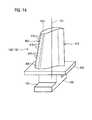
- FIG. 14shows a perspective view of a blade 120 or guide vane 130 of a turbomachine, which extends along a longitudinal axis 121.
- the turbomachinemay be a gas turbine of an aircraft or a power plant for power generation, a steam turbine or a compressor.
- the blade 120, 130has along the longitudinal axis 121 consecutively a fastening region 400, a blade platform 403 adjoining thereto and an airfoil 406.
- the blade 130may have at its blade tip 415 another platform (not shown).
- a blade root 183is formed, which serves for attachment of the blades 120, 130 to a shaft or a disc (not shown).
- the blade root 183is designed, for example, as a hammer head. Other designs as Christmas tree or Schwalbenschwanzfuß are possible.
- the blade 120, 130has a leading edge 409 and a trailing edge 412 for a medium flowing past the airfoil 406.
- Such superalloysare for example from EP 1 204 776 B1 .
- EP 1 306 454.
- the blade 120, 130can be made by a casting process, also by directional solidification, by a forging process, by a milling process or combinations thereof.
- Workpieces with a monocrystalline structure or structuresare used as components for machines which are exposed to high mechanical, thermal and / or chemical stresses during operation.
- Such monocrystalline workpiecestakes place e.g. by directed solidification from the melt.
- Theseare casting processes in which the liquid metallic alloy is transformed into a monocrystalline structure, i. to the single-crystal workpiece, or directionally solidified.
- dendritic crystalsare aligned along the heat flow and form either a columnar crystalline
- Grain structure(columnar, i.e. grains which extend over the entire length of the workpiece and here, in common usage, are referred to as directionally solidified) or a monocrystalline structure, i. the whole workpiece consists of one (single) crystal.
- directionally solidifiedi.e. grains which extend over the entire length of the workpiece and here, in common usage, are referred to as directionally solidified
- monocrystalline structurei. the whole workpiece consists of one (single) crystal.
- directionally solidified microstructureswhich means both single crystals that have no grain boundaries or at most small angle grain boundaries, and stem crystal structures that have probably longitudinal grain boundaries but no transverse grain boundaries. These second-mentioned crystalline structures are also known as directionally solidified structures. Such methods are known from U.S. Patent 6,024,792 and the EP 0 892 090 A1 known; these writings are part of the revelation.
- the blades 120, 130may be coatings against corrosion or oxidation (MCrAlX; M is at least one element of the group iron (Fe), cobalt (Co), nickel (Ni), X is an active element and is yttrium (Y) and / or silicon and / or at least one element of the rare earths or hafnium (Hf)).
- Mis at least one element of the group iron (Fe), cobalt (Co), nickel (Ni)
- Xis an active element and is yttrium (Y) and / or silicon and / or at least one element of the rare earths or hafnium (Hf)).
- Such alloysare known from the EP 0 486 489 B1 . EP 0 786 017 B1 . EP 0 412 397 B1 or EP 1 306 454 A1 which are to be part of this disclosure with regard to the chemical composition of the alloy.
- MCrAlXmay still be present a thermal barrier coating and consists for example of ZrO 2 , Y 2 O 3 -ZrO 2 , ie it is not, partially or completely stabilized by yttria and / or calcium oxide and / or magnesium oxide.
- Electron beam evaporationproduces stalk-shaped grains in the thermal barrier coating.
- Refurbishmentmeans that components 120, 130 may need to be deprotected after use (e.g., by sandblasting). This is followed by removal of the corrosion and / or oxidation layers or products. Optionally, even cracks in the component 120, 130 are repaired. This is followed by a re-coating of the component 120, 130 and a renewed use of the component 120, 130.
- the blade 120, 130may be hollow or solid. If the blade 120, 130 is to be cooled, it is hollow and may still film cooling holes 418 (indicated by dashed lines) on.
- the combustor 110is configured as a so-called annular combustor wherein a plurality of burners 107 circumferentially disposed about an axis of rotation 102 open into a common combustor space 154 that creates flames 156.
- the combustion chamber 110is configured in its entirety as an annular structure, which is positioned around the axis of rotation 102 around.
- the combustion chamber 110is designed for a comparatively high temperature of the working medium M of about 1000 ° C to 1600 ° C.
- the combustion chamber wall 153is provided on its side facing the working medium M side with an inner lining formed from heat shield elements 155.
- Each heat shield element 155 made of an alloyis working medium side with a particularly heat-resistant protective layer (MCrAlX layer and / or ceramic coating) or is made of high temperature resistant material (solid ceramic stones).
- Mis at least one element of the group iron (Fe), cobalt (Co), nickel (Ni), X is an active element and stands for yttrium (Y) and / or silicon and / or at least one element of the rare earths, or hafnium (Hf).
- MCrAlXmeans: M is at least one element of the group iron (Fe), cobalt (Co), nickel (Ni), X is an active element and stands for yttrium (Y) and / or silicon and / or at least one element of the rare earths, or hafnium (Hf).
- Such alloysare known from the EP 0 486 489 B1 .
- EP 0 412 397 B1 or EP 1 306 454 A1which are to be part of this disclosure with regard to the chemical composition of the alloy.
- a ceramic thermal barrier coatingmay be present and consists for example of ZrO 2 , Y 2 O 3 -ZrO 2 , ie it is not, partially or completely stabilized by yttria and / or calcium oxide and / or magnesium oxide.
- suitable coating processessuch as electron beam evaporation (EB-PVD), stalk-shaped grains are produced in the thermal barrier coating.
- Refurbishmentmeans that heat shield elements 155 may need to be deprotected (e.g., by sandblasting) after use. This is followed by removal of the corrosion and / or oxidation layers or products. If necessary, cracks in the heat shield element 155 are also repaired. This is followed by a recoating of the heat shield elements 155 and a renewed use of the heat shield elements 155.
- the heat shield elements 155are then, for example, hollow and possibly still have film cooling holes (not shown) which open into the combustion chamber space 154.
- FIG. 16shows by way of example a gas turbine 100 in a longitudinal partial section.
- the gas turbine 100has inside a rotatably mounted about a rotation axis 102 rotor 103 with a shaft 101, which is also referred to as a turbine runner.
- an intake housing 104a compressor 105, for example, a toroidal combustion chamber 110, in particular annular combustion chamber, with a plurality of coaxially arranged burners 107, a turbine 108 and the exhaust housing 109th
- a compressor 105for example, a toroidal combustion chamber 110, in particular annular combustion chamber, with a plurality of coaxially arranged burners 107, a turbine 108 and the exhaust housing 109th
- the annular combustion chamber 110communicates with an annular annular hot gas channel 111, for example.
- annular annular hot gas channel 111for example.
- turbine stages 112connected in series form the turbine 108.
- Each turbine stage 112is formed, for example, from two blade rings. As seen in the direction of flow of a working medium 113, in the hot gas channel 111 of a row of guide vanes 115, a series 125 formed of rotor blades 120 follows.
- the guide vanes 130are fastened to an inner housing 138 of a stator 143, whereas the moving blades 120 of a row 125 are attached to the rotor 103 by means of a turbine disk 133, for example.
- air 105is sucked in and compressed by the compressor 105 through the intake housing 104.
- the compressed air provided at the turbine-side end of the compressor 105is supplied to the burners 107 where it is mixed with a fuel.
- the mixtureis then burned to form the working fluid 113 in the combustion chamber 110.
- the working medium 113flows along the hot gas channel 111 past the guide vanes 130 and the rotor blades 120.
- the working medium 113relaxes on the rotor blades 120 in a pulse-transmitting manner, so that the blades 120 drive the rotor 103 and drive the machine coupled to it.
- the components exposed to the hot working medium 113are subject to thermal loads during operation of the gas turbine 100.
- the guide vanes 130 and rotor blades 120 of the first turbine stage 112, viewed in the flow direction of the working medium 113,are subjected to the greatest thermal stress in addition to the heat shield elements lining the annular combustion chamber 110.
- substrates of the componentsmay have a directional structure, i. they are monocrystalline (SX structure) or have only longitudinal grains (DS structure).
- iron-, nickel- or cobalt-based superalloysare used as the material for the components, in particular for the turbine blade 120, 130 and components of the combustion chamber 110.
- Such superalloysare for example from EP 1 204 776 B1 .
- EP 1 306 454.
- the blades 120, 130may be anti-corrosion coatings (MCrAlX; M is at least one element of the group iron (Fe), cobalt (Co), nickel (Ni), X is an active element and is yttrium (Y) and / or silicon and / or at least one element of the rare earths or hafnium).
- Mis at least one element of the group iron (Fe), cobalt (Co), nickel (Ni)
- Xis an active element and is yttrium (Y) and / or silicon and / or at least one element of the rare earths or hafnium).
- Such alloysare known from the EP 0 486 489 B1 .
- EP 0 412 397 B1 or EP 1 306 454 A1which should be part of this disclosure with regard to the chemical composition.
- MCrAlXmay still be present a thermal barrier coating, and consists for example of ZrO 2 , Y 2 O 3 -ZrO 2 , that is, it is not, partially or completely stabilized by yttria and / or calcium oxide and / or magnesium oxide.
- Electron beam evaporationproduces stalk-shaped grains in the thermal barrier coating.
- the vane 130has a guide vane foot (not shown here) facing the inner housing 138 of the turbine 108 and a vane head opposite the vane foot.
- the vane headfaces the rotor 103 and fixed to a mounting ring 140 of the stator 143.
Landscapes
- Engineering & Computer Science (AREA)
- Mechanical Engineering (AREA)
- General Engineering & Computer Science (AREA)
- Chemical & Material Sciences (AREA)
- Materials Engineering (AREA)
- Combustion & Propulsion (AREA)
- Turbine Rotor Nozzle Sealing (AREA)
- Cylinder Crankcases Of Internal Combustion Engines (AREA)
- Pens And Brushes (AREA)
- Superconductors And Manufacturing Methods Therefor (AREA)
Abstract
Translated fromGermanDescription
Translated fromGermanDie Erfindung betrifft ein Bauteil mit einem Filmkühlloch gemäß dem Oberbegriff des Anspruchs 1.The invention relates to a component with a film cooling hole according to the preamble of
Bauteile für Anwendungen bei hohen Temperaturen bestehen aus einer Superlegierung mit zusätzlichem Schutz gegen Oxidation, Korrosion und hohe Temperaturen. Hierzu weist das Substrat des Bauteils eine Korrosionsschutzschicht auf, auf der beispielsweise noch eine äußere keramische Wärmedämmschicht aufgebracht ist.
Zur zusätzlichen Kühlung werden noch Durchgangslöcher in das Substrat und die Schichten eingebracht, aus denen an der äußeren Oberfläche ein Kühlmedium austritt und zur Filmkühlung beiträgt. Dabei ist das Filmkühlloch in der Nähe der äußeren Oberfläche zu einem so genannten Diffusor verbreitert. Bei der Neuherstellung eines Bauteils mit einem Filmkühlloch ergeben sich Probleme, da der Diffusor sowohl durch die Schichten als auch größtenteils in das Substrat eingebracht wird. Beim Refurbishment, dem Wiederaufarbeiten von Bauteilen besteht das Problem darin, dass das Durchgangsloch schon vorhanden ist und das Substrat wieder beschichtet werden muss, so dass danach auch aus dem Diffusorbereich im Durchgangsloch Beschichtungsmaterial entfernt werden muss.Components for high temperature applications consist of a superalloy with additional protection against oxidation, corrosion and high temperatures. For this purpose, the substrate of the component has a corrosion protection layer on which, for example, an outer ceramic thermal barrier coating is still applied.
For additional cooling, through holes are also introduced into the substrate and the layers, from which a cooling medium emerges on the outer surface and contributes to film cooling. In this case, the film cooling hole is widened in the vicinity of the outer surface to a so-called diffuser. The re-manufacture of a component with a film cooling hole poses problems because the diffuser is introduced through both the layers and, for the most part, into the substrate. When refurbishment, the reprocessing of components, the problem is that the through hole is already present and the substrate must be coated again, so that then also from the diffuser area in the through hole coating material must be removed.
Die
Eine ähnliche symmetrische Verbreiterung eines Filmkühllochs ist in der
Die
Die
Die
Die
Es ist daher Aufgabe der Erfindung dieses Problem zu überwinden.It is therefore an object of the invention to overcome this problem.
Die Aufgabe wird gelöst durch ein Bauteil gemäß Anspruch 1.The object is achieved by a component according to
In den Unteransprüchen sind weitere vorteilhafte Maßnahmen aufgelistet, die beliebig in vorteilhafter Art und Weise miteinander verbunden werden können.In the subclaims further advantageous measures are listed, which can be connected to each other in an advantageous manner.
Es zeigen
- Figur 1 - 7, 9 - 12
- Ausgestaltungen eines Filmkühllochs,
- Figuren 8
- Ausführungsbeispiel eines erfindungsgemäßen Bauteils mit einem Filmkühlloch,
Figur 13- zeigt eine Aufsicht auf ein Filmkühlloch,
Figur 14- eine Turbinenschaufel,
- Figur 15
- eine Brennkammer,
Figur 16- eine Gasturbine.
- Figure 1-7, 9-12
- Embodiments of a film cooling hole,
- FIGS. 8
- Embodiment of a component according to the invention with a film cooling hole,
- FIG. 13
- shows a plan view of a film cooling hole,
- FIG. 14
- a turbine blade,
- FIG. 15
- a combustion chamber,
- FIG. 16
- a gas turbine.
Das Substrat 4 und die Schicht 7 weisen zumindest ein Filmkühlloch 28 auf, das auf der unter den betrieblichen Einsatzbedingungen heißen Seite 22 einen Diffusor 13 aufweist, der von der beispielsweise zylindrischen, quaderförmigen oder allgemein gesagt symmetrischen Kontur 49 des unteren Teils 24 des Filmkühllochs 28 nahe eines Kühlreservoir 31 abweicht und sich im Querschnitt vergrößert.The
Das Filmkühlloch 28 besteht also aus einem unteren Teil 24 und dem äußeren Diffusor 13. Der Diffusor 13 hat eine Austrittsöffnung 58, die von einem Heißgas in Überströmrichtung Der Diffusor 13 ist gebildet aus einer gedachten Fortsetzung 12 der Kontur 49 bis zur Oberfläche 25 und einem Zusatz 14 (
In der Querschnittsansicht der
In der Ebene der äußeren Oberfläche weist der Diffusor 13 also keine Drehsymmetrie auf, wobei der Schwerpunkt der asymmetrischen Form von dem Schwerpunkt der symmetrischen Form der Kontur 49 in Überstromrichtung 37 verschoben ist. Entlang der Senkrechten 27 zur äußeren Oberfläche 25 hin wird die Querschnittsfläche des Filmkühllochs 28, auf der die Senkrechte 27 senkrecht steht, größer, d.h. der Diffusor 13 ist ganz oder vorzugsweise teilweise trichterförmig ausgebildet.The
In the cross-sectional view of
In the plane of the outer surface of the
Erfindungsgemäß ist der Diffusor 13 zum größten Teil innerhalb der einzigen Schicht 7 angeordnet, d.h., wenn der Diffusor 13 sich mit einer Gesamtlänge 19 in die Tiefe längs einer Senkrechten 27 des Bauteils 1, die senkrecht auf der äußeren Oberfläche 25 oder senkrecht zur Überströmrichtung 37 steht, erstreckt, so ergibt sich eine Substratlänge 16 des Diffusors 13, die den Anteil des Diffusors 13 im Substrat 4 darstellt. Die Substratlänge 16 ist deutlich kleiner ausgebildet als die Gesamtlänge 19. Die gesamte Beschichtungsdicke 26 (hier die der Schicht 7) bildet den restlichen Teil der Gesamtlänge 19 des Diffusors 13. Die Beschichtungsdicke 26 beträgt mindestens 50%, vorzugsweise mindestens 60% oder mindestens 70%, insbesondere 80% oder 90% der Gesamtlänge 19.According to the invention, the
Alternativ kann der Diffusor 13 vollständig in der einzigen Schicht 7 angeordnet sein (
In der
Dies ist wiederum eine Korrosions- und Oxidationsschutzschicht 7, auf der noch eine äußere keramische Wärmedämmschicht 10 aufgebracht ist.
Ebenso wie in
Ebenso kann der Diffusor 13 vollständig in den zwei Schichten 7, 10 angeordnet sein (
Entsprechend den zwei Schichten gemäß
This in turn is a corrosion and
As well as in
Likewise, the
According to the two layers according to
Dadurch dass der Diffusor 13 größtenteils oder ganz in den Schichten 7, 10 angeordnet ist, ergeben sich Vorteile beim Wiederaufarbeiten des Bauteils 1 beispielsweise hinsichtlich eines Laserabtragens oder eines Entfernens von Material oberhalb des unteren Teils 24, das nach dem Neubeschichten des Bauteils 1 die Austrittsöffnung 58 verdeckt, nämlich dadurch, dass der Laser oder sonstige Bearbeitungsapparaturen nur auf das Material der Schichten 7, 10 eingestellt werden muss und die Bearbeitung des anderen Materials, nämlich das des Substrats 4, nicht beachtet werden muss.As a result of the fact that the
Das Substrat 4 weist eine äußere Oberfläche 43 auf, auf der die zumindest eine Schicht 7, 10 aufgebracht ist.
Der Diffusor 13 ist beispielsweise größtenteils (gem.
The
The
Der untere Teil 24 des Filmkühllochs 28 weist im Längsschnitt beispielsweise eine Symmetrielinie 46 auf.The
Die Symmetrielinie 46 stellt beispielsweise auch eine Ausströmrichtung 46 für ein Kühlmedium dar, das das Filmkühlloch 28 durchströmt.
Eine Konturlinie 47, die parallel zur Symmetrielinie 46 auf der Innenseite des Filmkühllochs 28 verläuft oder eine Projektion der Symmetrielinie 46 auf die Innenseite des unteren Teils 24 des Filmkühllochs 28 darstellt, bildet einen spitzen Winkel α1 mit der äußeren Oberfläche 43, der insbesondere bei 30° +/- 10% liegt. Das Filmkühlloch 28 ist also in Überströmrichtung 37 geneigt.
Die Kantenlänge a28 (
A
The edge length a28 (
Die Konturlinie 47, die entlang der Kontur 49 des unteren Teils 24 vorzugsweise parallel zur Ausströmrichtung 46 verläuft, weist einen spitzen Winkel α2 mit einer Diffusorlinie 48 auf, die auf der Innenfläche 50 des Zusatzes 14 des Diffusors 13 verläuft und die eine Projektion der Überströmrichtung 37 auf die Innenfläche 50 des Zusatzes 14 des Diffusors 13 darstellt.
Der Winkel α2 beträgt insbesondere 10° +/- 10%.
Der untere Teil 24 entlang der Symmetrielinie 46 weist einen konstanten Querschnitt auf, der insbesondere eine n-zahlige Drehsymmetrie (quadratisch, rechteckig, rund, oval,...) aufweist.The
The angle α2 is in particular 10 ° +/- 10%.
The
Der Diffusor 13 entsteht dadurch, dass sich die Querschnittsfläche des Filmkühllochs 28 verbreitert, also im Längsschnitt trichterförmig ausgebildet ist. Der Zusatz 14 zu der Kontur 49 erstreckt sich nicht notwendigerweise vollständig um die Austrittsöffnung 58 des Filmkühllochs 28 herum, sondern nur teilweise, insbesondere um die Hälfte oder weniger des Umfangs der Austrittsöffnung 58.
Vorzugsweise ist der Diffusor 13 nur - in Überströmrichtung 37 des Heißgases 22 gesehen - im hinteren Bereich der Öffnung 58 angeordnet (
Preferably, the
Die gesamte Schichtdicke der zumindest einen Schicht 7, 10 beträgt etwa 400µm bis 700µm, insbesondere 600µm.The total layer thickness of the at least one
In der Ebene der Oberfläche 25 weist der Zusatz 14 des Diffusors 13 in Überströmrichtung 37 eine Längslänge l1 vorzugsweise von etwa 3mm auf.In the plane of the
Die größte Breite, d. h. die größte Querlänge l2 des Diffusors 13 in der Oberfläche, also senkrecht zur Überströmrichtung 37 gemessen, weist vorzugsweise eine Größe von 2 +- 0,2 mm bei Laufschaufeln und eine Größe von 4 +- 0,2 mm bei Leitschaufeln auf und beträgt höchstens 8mm.The largest width, ie the largest transverse length l2 of the
Beim Ausführungsbeispiel der
Die Überströmrichtung 37 bildet mit einer seitlichen Begrenzungslinie 38 des Zusatzes 14 in der Ebene der äußeren Oberfläche 25 einen spitzen Winkel α3, insbesondere 10° +/- 10%.The
Vorzugsweise abweichend von der Kontur 49 des beispielsweise bezüglich zweier aufeinander senkrecht stehender Achsen symmetrischen unteren Teils 24 verbreitert sich der Diffusor 13 quer zur Überströmrichtung 37 jeweils um einen Winkel α3, der insbesondere 10° +/- 10% beträgt, wobei die Verbreiterung bereits an einer Vorderkante 61 (in Überströmrichtung 37 gesehen) des Filmkühllochs 28 beginnt und sich bis zur Hinterkante 64 erstreckt.Preferably, deviating from the
Daher hat der Diffusor 13 in der Ebene der Oberfläche 25 einen trapezförmigen Querschnitt (
Der Diffusor 13 wird durch ein Materialabtragungsverfahren, beispielsweise Elektronenbestrahlung oder Laserbestrahlung erzeugt. Nur so lässt sich eine Vielzahl von Kühllöchern genau und in reproduzierbarer Weise erzeugen.The
Die
Der untere Teil 24 des Filmkühllochs 28 ist hier nur beispielhaft quaderförmig ausgebildet, kann jedoch auch eine runde oder ovale Querschnittsform aufweisen.The
In
Ausgehend von
In
Das Filmkühlloch 28 besteht beispielsweise aus einem quaderförmigen unteren Teil 24, an dem sich ein Diffusor 13 in Form eines Hexaeders mit parallelen, trapezförmigen Seitenflächen anschließt.The
In
Den
In
In
Eine Verbreiterung des Querschnitts des Filmkühllochs 28 auf der Höhe der äußeren Oberfläche 25 entgegen der Überströmrichtung 37, d. h. vor der Vorderkante 61 ist nicht vorhanden oder nur in geringem Umfang im Vergleich zu der Verbreiterung des Querschnitts in Überströmrichtung 37.A widening of the cross section of the
Die Strömungsmaschine kann eine Gasturbine eines Flugzeugs oder eines Kraftwerks zur Elektrizitätserzeugung, eine Dampfturbine oder ein Kompressor sein.The turbomachine may be a gas turbine of an aircraft or a power plant for power generation, a steam turbine or a compressor.
Die Schaufel 120, 130 weist entlang der Längsachse 121 aufeinander folgend einen Befestigungsbereich 400, eine daran angrenzende Schaufelplattform 403 sowie ein Schaufelblatt 406 auf.The
Als Leitschaufel 130 kann die Schaufel 130 an ihrer Schaufelspitze 415 eine weitere Plattform aufweisen (nicht dargestellt).As a
Im Befestigungsbereich 400 ist ein Schaufelfuß 183 gebildet, der zur Befestigung der Laufschaufeln 120, 130 an einer Welle oder einer Scheibe dient (nicht dargestellt).In the mounting
Der Schaufelfuß 183 ist beispielsweise als Hammerkopf ausgestaltet. Andere Ausgestaltungen als Tannenbaum- oder Schwalbenschwanzfuß sind möglich.The
Die Schaufel 120, 130 weist für ein Medium, das an dem Schaufelblatt 406 vorbeiströmt, eine Anströmkante 409 und eine Abströmkante 412 auf.The
Bei herkömmlichen Schaufeln 120, 130 werden in allen Bereichen 400, 403, 406 der Schaufel 120, 130 beispielsweise massive metallische Werkstoffe, insbesondere Superlegierungen verwendet.In
Solche Superlegierungen sind beispielsweise aus der
Die Schaufel 120, 130 kann hierbei durch ein Gussverfahren, auch mittels gerichteter Erstarrung, durch ein Schmiedeverfahren, durch ein Fräsverfahren oder Kombinationen daraus gefertigt sein.The
Werkstücke mit einkristalliner Struktur oder Strukturen werden als Bauteile für Maschinen eingesetzt, die im Betrieb hohen mechanischen, thermischen und/oder chemischen Belastungen ausgesetzt sind.Workpieces with a monocrystalline structure or structures are used as components for machines which are exposed to high mechanical, thermal and / or chemical stresses during operation.
Die Fertigung von derartigen einkristallinen Werkstücken erfolgt z.B. durch gerichtetes Erstarren aus der Schmelze. Es handelt sich dabei um Gießverfahren, bei denen die flüssige metallische Legierung zur einkristallinen Struktur, d.h. zum einkristallinen Werkstück, oder gerichtet erstarrt.The production of such monocrystalline workpieces takes place e.g. by directed solidification from the melt. These are casting processes in which the liquid metallic alloy is transformed into a monocrystalline structure, i. to the single-crystal workpiece, or directionally solidified.
Dabei werden dendritische Kristalle entlang dem Wärmefluss ausgerichtet und bilden entweder eine stängelkristallineHere, dendritic crystals are aligned along the heat flow and form either a columnar crystalline
Kornstruktur (kolumnar, d.h. Körner, die über die ganze Länge des Werkstückes verlaufen und hier, dem allgemeinen Sprachgebrauch nach, als gerichtet erstarrt bezeichnet werden) oder eine einkristalline Struktur, d.h. das ganze Werkstück besteht aus einem (einzigen) Kristall. In diesen Verfahren muss man den Übergang zur globulitischen (polykristallinen) Erstarrung meiden, da sich durch ungerichtetes Wachstum notwendigerweise transversale und longitudinale Korngrenzen ausbilden, welche die guten Eigenschaften des gerichtet erstarrten oder einkristallinen Bauteiles zunichte machen.Grain structure (columnar, i.e. grains which extend over the entire length of the workpiece and here, in common usage, are referred to as directionally solidified) or a monocrystalline structure, i. the whole workpiece consists of one (single) crystal. In these processes, it is necessary to avoid the transition to globulitic (polycrystalline) solidification, since non-directional growth necessarily forms transverse and longitudinal grain boundaries which negate the good properties of the directionally solidified or monocrystalline component.
Ist allgemein von gerichtet erstarrten Gefügen die Rede, so sind damit sowohl Einkristalle gemeint, die keine Korngrenzen oder höchstens Kleinwinkelkorngrenzen aufweisen, als auch Stängelkristallstrukturen, die wohl in longitudinaler Richtung verlaufende Korngrenzen, aber keine transversalen Korngrenzen aufweisen. Bei diesen zweitgenannten kristallinen Strukturen spricht man auch von gerichtet erstarrten Gefügen (directionally solidified structures).
Solche Verfahren sind aus der
Such methods are known from
Ebenso können die Schaufeln 120, 130 Beschichtungen gegen Korrosion oder Oxidation (MCrAlX; M ist zumindest ein Element der Gruppe Eisen (Fe), Kobalt (Co), Nickel (Ni), X ist ein Aktivelement und steht für Yttrium (Y) und/oder Silizium und/oder zumindest ein Element der Seltenen Erden bzw. Hafnium (Hf)). Solche Legierungen sind bekannt aus der
Auf der MCrAlX kann noch eine Wärmedämmschicht vorhanden sein und besteht beispielsweise aus ZrO2, Y2O3-ZrO2, d.h. sie ist nicht, teilweise oder vollständig stabilisiert durch Yttriumoxid und/oder Kalziumoxid und/oder Magnesiumoxid.On the MCrAlX may still be present a thermal barrier coating and consists for example of ZrO2 , Y2 O3 -ZrO2 , ie it is not, partially or completely stabilized by yttria and / or calcium oxide and / or magnesium oxide.
Durch geeignete Beschichtungsverfahren wie z.B. Elektronenstrahlverdampfen (EB-PVD) werden stängelförmige Körner in der Wärmedämmschicht erzeugt.By suitable coating methods, e.g. Electron beam evaporation (EB-PVD) produces stalk-shaped grains in the thermal barrier coating.
Wiederaufarbeitung (Refurbishment) bedeutet, dass Bauteile 120, 130 nach ihrem Einsatz gegebenenfalls von Schutzschichten befreit werden müssen (z.B. durch Sandstrahlen). Danach erfolgt eine Entfernung der Korrosions- und/oder Oxidationsschichten bzw. -produkte. Gegebenenfalls werden auch noch Risse im Bauteil 120, 130 repariert. Danach erfolgt eine Wiederbeschichtung des Bauteils 120, 130 und ein erneuter Einsatz des Bauteils 120, 130.Refurbishment means that
Die Schaufel 120, 130 kann hohl oder massiv ausgeführt sein. Wenn die Schaufel 120, 130 gekühlt werden soll, ist sie hohl und weist ggf. noch Filmkühllöcher 418 (gestrichelt angedeutet) auf.The
Die
Zur Erzielung eines vergleichsweise hohen Wirkungsgrades ist die Brennkammer 110 für eine vergleichsweise hohe Temperatur des Arbeitsmediums M von etwa 1000°C bis 1600°C ausgelegt. Um auch bei diesen, für die Materialien ungünstigen Betriebsparametern eine vergleichsweise lange Betriebsdauer zu ermöglichen, ist die Brennkammerwand 153 auf ihrer dem Arbeitsmedium M zugewandten Seite mit einer aus Hitzeschildelementen 155 gebildeten Innenauskleidung versehen.
Jedes Hitzeschildelement 155 aus einer Legierung ist arbeitsmediumsseitig mit einer besonders hitzebeständigen Schutzschicht (MCrAlX-Schicht und/oder keramische Beschichtung) ausgestattet oder ist aus hochtemperaturbeständigem Material (massive keramische Steine) gefertigt.
Diese Schutzschichten können ähnlich der Turbinenschaufeln sein, also bedeutet beispielsweise MCrAlX: M ist zumindest ein Element der Gruppe Eisen (Fe), Kobalt (Co), Nickel (Ni), X ist ein Aktivelement und steht für Yttrium (Y) und/oder Silizium und/oder zumindest ein Element der Seltenen Erden, bzw. Hafnium (Hf). Solche Legierungen sind bekannt aus der
Each
These protective layers may be similar to the turbine blades, so for example MCrAlX means: M is at least one element of the group iron (Fe), cobalt (Co), nickel (Ni), X is an active element and stands for yttrium (Y) and / or silicon and / or at least one element of the rare earths, or hafnium (Hf). Such alloys are known from the
Auf der MCrAlX kann noch eine beispielsweise keramische Wärmedämmschicht vorhanden sein und besteht beispielsweise aus ZrO2, Y2O3-ZrO2, d.h. sie ist nicht, teilweise oder vollständig stabilisiert durch Yttriumoxid und/oder Kalziumoxid und/oder Magnesiumoxid.
Durch geeignete Beschichtungsverfahren wie z.B. Elektronenstrahlverdampfen (EB-PVD) werden stängelförmige Körner in der Wärmedämmschicht erzeugt.On the MCrAlX, for example, a ceramic thermal barrier coating may be present and consists for example of ZrO2 , Y2 O3 -ZrO2 , ie it is not, partially or completely stabilized by yttria and / or calcium oxide and / or magnesium oxide.
By means of suitable coating processes, such as electron beam evaporation (EB-PVD), stalk-shaped grains are produced in the thermal barrier coating.
Wiederaufarbeitung (Refurbishment) bedeutet, dass Hitzeschildelemente 155 nach ihrem Einsatz gegebenenfalls von Schutzschichten befreit werden müssen (z.B. durch Sandstrahlen). Danach erfolgt eine Entfernung der Korrosions- und/oder Oxidationsschichten bzw. -produkte. Gegebenenfalls werden auch noch Risse in dem Hitzeschildelement 155 repariert. Danach erfolgt eine Wiederbeschichtung der Hitzeschildelemente 155 und ein erneuter Einsatz der Hitzeschildelemente 155.Refurbishment means that
Aufgrund der hohen Temperaturen im Inneren der Brennkammer 110 kann zudem für die Hitzeschildelemente 155 bzw. für deren Halteelemente ein Kühlsystem vorgesehen sein. Die Hitzeschildelemente 155 sind dann beispielsweise hohl und weisen ggf. noch in den Brennkammerraum 154 mündende Filmkühllöcher (nicht dargestellt) auf.Due to the high temperatures inside the
Die
Die Gasturbine 100 weist im Inneren einen um eine Rotationsachse 102 drehgelagerten Rotor 103 mit einer Welle 101 auf, der auch als Turbinenläufer bezeichnet wird.The
Entlang des Rotors 103 folgen aufeinander ein Ansauggehäuse 104, ein Verdichter 105, eine beispielsweise torusartige Brennkammer 110, insbesondere Ringbrennkammer, mit mehreren koaxial angeordneten Brennern 107, eine Turbine 108 und das Abgasgehäuse 109.Along the
Die Ringbrennkammer 110 kommuniziert mit einem beispielsweise ringförmigen Heißgaskanal 111. Dort bilden beispielsweise vier hintereinander geschaltete Turbinenstufen 112 die Turbine 108.The
Jede Turbinenstufe 112 ist beispielsweise aus zwei Schaufelringen gebildet. In Strömungsrichtung eines Arbeitsmediums 113 gesehen folgt im Heißgaskanal 111 einer Leitschaufelreihe 115 eine aus Laufschaufeln 120 gebildete Reihe 125.Each
Die Leitschaufeln 130 sind dabei an einem Innengehäuse 138 eines Stators 143 befestigt, wohingegen die Laufschaufeln 120 einer Reihe 125 beispielsweise mittels einer Turbinenscheibe 133 am Rotor 103 angebracht sind.The guide vanes 130 are fastened to an inner housing 138 of a stator 143, whereas the moving
An dem Rotor 103 angekoppelt ist ein Generator oder eine Arbeitsmaschine (nicht dargestellt).Coupled to the
Während des Betriebes der Gasturbine 100 wird vom Verdichter 105 durch das Ansauggehäuse 104 Luft 135 angesaugt und verdichtet. Die am turbinenseitigen Ende des Verdichters 105 bereitgestellte verdichtete Luft wird zu den Brennern 107 geführt und dort mit einem Brennmittel vermischt. Das Gemisch wird dann unter Bildung des Arbeitsmediums 113 in der Brennkammer 110 verbrannt. Von dort aus strömt das Arbeitsmedium 113 entlang des Heißgaskanals 111 vorbei an den Leitschaufeln 130 und den Laufschaufeln 120. An den Laufschaufeln 120 entspannt sich das Arbeitsmedium 113 impulsübertragend, so dass die Laufschaufeln 120 den Rotor 103 antreiben und dieser die an ihn angekoppelte Arbeitsmaschine.During operation of the
Die dem heißen Arbeitsmedium 113 ausgesetzten Bauteile unterliegen während des Betriebes der Gasturbine 100 thermischen Belastungen. Die Leitschaufeln 130 und Laufschaufeln 120 der in Strömungsrichtung des Arbeitsmediums 113 gesehen ersten Turbinenstufe 112 werden neben den die Ringbrennkammer 110 auskleidenden Hitzeschildelementen am meisten thermisch belastet.The components exposed to the hot working
Um den dort herrschenden Temperaturen standzuhalten, können diese mittels eines Kühlmittels gekühlt werden.To withstand the prevailing temperatures, they can be cooled by means of a coolant.
Ebenso können Substrate der Bauteile eine gerichtete Struktur aufweisen, d.h. sie sind einkristallin (SX-Struktur) oder weisen nur längsgerichtete Körner auf (DS-Struktur).Likewise, substrates of the components may have a directional structure, i. they are monocrystalline (SX structure) or have only longitudinal grains (DS structure).
Als Material für die Bauteile, insbesondere für die Turbinenschaufel 120, 130 und Bauteile der Brennkammer 110 werden beispielsweise eisen-, nickel- oder kobaltbasierte Superlegierungen verwendet.As the material for the components, in particular for the
Solche Superlegierungen sind beispielsweise aus der
Ebenso können die Schaufeln 120, 130 Beschichtungen gegen Korrosion (MCrAlX; M ist zumindest ein Element der Gruppe Eisen (Fe), Kobalt (Co), Nickel (Ni), X ist ein Aktivelement und steht für Yttrium (Y) und/oder Silizium und/oder zumindest ein Element der Seltenen Erden bzw. Hafnium). Solche Legierungen sind bekannt aus der
Auf der MCrAlX kann noch eine Wärmedämmschicht vorhanden sein, und besteht beispielsweise aus ZrO2, Y2O3-ZrO2, d.h. sie ist nicht, teilweise oder vollständig stabilisiert durch Yttriumoxid und/oder Kalziumoxid und/oder Magnesiumoxid.On the MCrAlX may still be present a thermal barrier coating, and consists for example of ZrO2 , Y2 O3 -ZrO2 , that is, it is not, partially or completely stabilized by yttria and / or calcium oxide and / or magnesium oxide.
Durch geeignete Beschichtungsverfahren wie z.B. Elektronenstrahlverdampfen (EB-PVD) werden stängelförmige Körner in der Wärmedämmschicht erzeugt.By suitable coating methods, e.g. Electron beam evaporation (EB-PVD) produces stalk-shaped grains in the thermal barrier coating.
Die Leitschaufel 130 weist einen dem Innengehäuse 138 der Turbine 108 zugewandten Leitschaufelfuß (hier nicht dargestellt) und einen dem Leitschaufelfuß gegenüberliegenden Leitschaufelkopf auf. Der Leitschaufelkopf ist dem Rotor 103 zugewandt und an einem Befestigungsring 140 des Stators 143 festgelegt.The
Claims (13)
Translated fromGermanwobei das Bauteil (1) besteht aus
einem Substrat (4) und
zumindest einer Schicht (7, 10),
wobei das Filmkühlloch (28) im äußeren Bereich einen Diffusor (13) aufweist,
dadurch gekennzeichnet,
dass der gesamte Diffusor (13) größtenteils in der zumindest einen Schicht (7, 10) angeordnet ist,
dass die gesamte Beschichtungsdicke (26) mindestens 60%, insbesondere 70%,
der entlang einer Senkrechten (27) zur äußeren Oberfläche (25) der mindestens einen Schicht (7, 10) gemessenen Gesamtlänge (19) des Diffusors (13) beträgt,
dass ein Heißgas das Filmkühlloch (28) in Überströmrichtung (37) überströmt,
dass ein Medium das Filmkühlloch (28) in Ausströmrichtung (46) durchströmt,
dass das Filmkühlloch (28) einen unteren Teil (24) aufweist,
dass der Diffusor (13) als Teil des Filmkühllochs (28) sich an den unteren Teil (24) anschließt,
dass eine Konturlinie (47) entlang der Kontur (49) des unteren Teils (24) parallel zur Ausströmrichtung (46) verläuft,
dass eine Diffusorlinie (48) auf der Innenseite des Diffusors (13) verläuft,
die (48) eine Projektion der Überströmrichtung (37) auf die Innenfläche eines Zusatzes (14) des Diffusors (13) ist,
unddass die Diffusorlinie (48) einen spitzen Winkel (α2), insbesondere von 10°,
mit der Konturlinie (47) aufweist,
dass ein Heißgas das Filmkühlloch (28) in Überströmrichtung (37) überströmt,
dass ein Medium das Filmkühlloch (28) in Ausströmrichtung (46) durchströmt,
dass das Filmkühlloch (28) einen unteren Teil (24) aufweist,
dass der Diffusor (13) als Teil des Filmkühllochs (28) sich an den unteren Teil (24) anschließt
und in Ausströmrichtung (46) einen sich senkrecht zur Ausströmrichtung (46) verbreiternden Querschnitt aufweist, wobei der Querschnitt des Diffusors (13) sich insbesondere nur in Überströmrichtung (37) verbreitert.Component with at least one film cooling hole (28),
wherein the component (1) consists of
a substrate (4) and
at least one layer (7, 10),
wherein the film cooling hole (28) has a diffuser (13) in the outer region,
characterized,
that the entire diffuser (13) is arranged for the most part in the at least one layer (7, 10),
that the total coating thickness (26) is at least 60%, in particular 70%,
the total length (19) of the diffuser (13) measured along a vertical (27) to the outer surface (25) of the at least one layer (7, 10),
that a hot gas flows over the film cooling hole (28) in the overflow (37),
that a medium flows through the film cooling hole (28) in the outflow (46),
that the film-cooling hole (28) having a lower portion (24),
in that the diffuser (13), as part of the film cooling hole (28), adjoins the lower part (24),
that a contour line (47) along the contour (49) of the lower part (24) runs parallel to the outflow direction (46),
that a diffuser line (48) on the inside of the diffuser (13) extends,
(48) is a projection of the overflow direction (37) on the inner surface of an additive (14) of the diffuser (13),
andthat the diffuser line (48) has an acute angle (α2), in particular of 10 °,
having the contour line (47),
that a hot gas, the film cooling hole (28) in the overflow direction (37) overflowed,
that a medium flows through the film cooling hole (28) in the outflow (46),
that the film-cooling hole (28) having a lower portion (24),
in that the diffuser (13), as part of the film cooling hole (28), adjoins the lower part (24)
and in the outflow direction (46) has a perpendicular to the outflow direction (46) widening cross section, wherein the cross section of the diffuser (13) widened in particular only in the overflow direction (37).
dadurch gekennzeichnet, dass
die Beschichtungsdicke (26) mindestens 80%,
insbesondere 90% der Gesamtlänge (19) des Diffusors (13) beträgt.Component according to claim 1,
characterized in that
the coating thickness (26) at least 80%,
in particular 90% of the total length (19) of the diffuser (13).
dadurch gekennzeichnet, dass
die Beschichtungsdicke (26) gleich der Gesamtlänge (19) des Diffusors (13) ist.Component according to claim 1,
characterized in that
the coating thickness (26) is equal to the total length (19) of the diffuser (13).
dadurch gekennzeichnet,
dass das Substrat (4) eine äußere Oberfläche (43) aufweist, und dass das Filmkühlloch (28) unter einem von 0° verschiedenen spitzen Winkel (α1) zur äußeren Oberfläche (43), insbesondere von 30° - 45°,
in der mindestens einen Schicht (7, 10) verläuft.Component according to claim 1, 2 or 3
characterized,
in that the substrate (4) has an outer surface (43), and in that the film cooling hole (28) extends at an acute angle (α1) different from 0 ° to the outer surface (43), in particular from 30 ° to 45 °,
in the at least one layer (7, 10) extends.
dass ein Heißgas das Filmkühlloch (28) in Überströmrichtung (37) überströmt,
dass das Filmkühlloch (28) einen unteren Teil (24) aufweist, dass der Diffusor (13) als Teil des Filmkühllochs (28) sich an den unteren Teil (24) anschließt und
dass der Diffusor (13) sich in der Ebene der äußeren Oberfläche (25) der Schicht (7, 10) in Überströmrichtung (37) um einen spitzen Winkel (α3) zur Überströmrichtung (37), insbesondere um 10°,
quer zur Überströmrichtung (37) verbreitert.Component according to one or more of the preceding claims,characterized
that a hot gas flows over the film cooling hole (28) in the overflow (37),
that the film cooling hole (28) has a lower part (24), that the diffuser (13) as part of the film cooling hole (28) adjoins the lower part (24) and
that the diffuser (13) located in the plane of the outer surface (25) of the layer (7, 10) in the overflow (37) at an acute angle (α3) to the overflow (37), in particular by 10 °,
widens transversely to the overflow (37).
dass ein Heißgas das Filmkühlloch (28) in Überströmrichtung (37) überströmt,
dass ein Medium das Filmkühlloch (28) in Ausströmrichtung (46) durchströmt,
dass das Filmkühlloch (28) einen unteren Teil (24) aufweist, dass der Diffusor (13) als Teil des Filmkühllochs (28) sich an den unteren Teil (24) anschließt
und in Ausströmrichtung (46) einen sich senkrecht zur Ausströmrichtung (46) verbreiternden Querschnitt aufweist, wobei die Fläche des Diffusors (13) in Überströmrichtung (37) gesehen auf Höhe der Oberfläche (25) größtenteils hinter dem Filmkühlloch (28) angeordnet ist.Component according to one or more of the preceding claims,characterized
that a hot gas flows over the film cooling hole (28) in the overflow (37),
that a medium flows through the film cooling hole (28) in the outflow (46),
in that the film cooling hole (28) has a lower part (24) such that the diffuser (13) as part of the film cooling hole (28) adjoins the lower part (24)
and in the outflow direction (46) has a perpendicular to the outflow direction (46) widening cross section, wherein the surface of the diffuser (13) seen in the overflow (37) at the level of the surface (25) is arranged largely behind the film cooling hole (28).
dadurch gekennzeichnet,
dass die Austrittöffnung (58) des Filmkühllochs (28) in Überströmrichtung (37) eine Vorderkante (61) und eine Hinterkante (64) aufweist und
dass sich der Diffusor (13) in der Ebene der Austrittsöffnung von der Vorderkante (61) ausgehend verbreitert, sodass der Diffusor (13) in der Ebene der äußeren Oberfläche (25) trapezförmig ausgebildet ist.Component according to claim 5,
characterized,
that the outlet opening (58) of the film cooling hole (28) in the overflow direction (37) has a front edge (61) and a trailing edge (64) and
in that the diffuser (13) widened in the plane of the outlet opening starting from the front edge (61), so that the diffuser (13) is trapezoidal in the plane of the outer surface (25).
dadurch gekennzeichnet,
dass der Diffusor (13) aus einer Fortsetzung der Kontur (49) des unteren Teils (24) und einem Zusatz (14) besteht und
dass nur der Zusatz (14) des Diffusors (13) sich so zur äußeren Oberfläche (25) hin verbreitert,
dass er (14) in der Ebene der äußeren Oberfläche (25) trapezförmig ist.Component according to claim 5,
characterized,
that the diffuser (13) consists of a continuation of the contour (49) of the lower part (24) and an additive (14), and
that only the additive (14) of the diffuser (13) widens towards the outer surface (25),
that it (14) is trapezoidal in the plane of the outer surface (25).
dadurch gekennzeichnet,
dass zwischen der Überströmrichtung (37) und einer seitlichen Begrenzungslinie (38) des Zusatzes (14) des Diffusors (13) in der Ebene der Oberfläche (25) ein spitzer Winkel von (α3),
insbesondere von 10°,
gegeben ist.Component according to claim 7,
characterized,
that between the overflow (37) and a lateral boundary line (38) Extension (14) of the diffuser (13) in the plane of the surface (25) an acute angle (α3),
in particular of 10 °,
given is.
dadurch gekennzeichnet,
dass der Diffusor (13) in der Ebene der äußeren Oberfläche (25) in Überströmrichtung (37) eine Längslänge (l1) aufweist,
die insbesondere 3mm beträgt, und
dass die breiteste Querlänge (l2) senkrecht zur Längslänge (l1) höchstens 10mm,
insbesondere 2 bis 4mm beträgt.Component according to claim 4 or 5,
characterized,
that the diffuser (13) in the plane of the outer surface (25) has a longitudinal length in the overflow (37) (l1),
which is 3mm in particular, and
that the widest transverse length (l2 ) perpendicular to the longitudinal length (l1 ) at most 10mm,
especially 2 to 4mm.
dadurch gekennzeichnet, dass
eine äußere Schicht (10) auf einer zwischenliegenden Schicht (7) aufgebracht ist.Component according to claim 1, 2 or 3,
characterized in that
an outer layer (10) is applied to an intermediate layer (7).
dadurch gekennzeichnet,
dass die zwischen liegende Schicht (7) aus der Legierung des Typs MCrAlX besteht und
dass die äußere Schicht (10) insbesondere eine keramische Wärmedämmschicht darstellt.Component according to claim 10,
characterized,
that the intermediate layer (7) consists of the alloy MCrAlX and
that the outer layer (10) is in particular a ceramic thermal barrier coating.
dadurch gekennzeichnet, dass
das Bauteil (1) ein Bauteil einer Dampf- oder Gasturbine (100),
insbesondere eine Turbinenschaufel (120, 130),
ein Hitzeschildelement (155) ist.Component according to claim 1, 10 or 11,
characterized in that
the component (1) is a component of a steam or gas turbine (100),
in particular a turbine blade (120, 130),
a heat shield element (155).
Priority Applications (1)
| Application Number | Priority Date | Filing Date | Title |
|---|---|---|---|
| EP11008538.8AEP2428646B1 (en) | 2005-04-12 | 2006-03-16 | Component with film cooling holes |
Applications Claiming Priority (4)
| Application Number | Priority Date | Filing Date | Title |
|---|---|---|---|
| EP05007993AEP1712739A1 (en) | 2005-04-12 | 2005-04-12 | Component with film cooling hole |
| EP11008538.8AEP2428646B1 (en) | 2005-04-12 | 2006-03-16 | Component with film cooling holes |
| EP10006981AEP2292898A1 (en) | 2005-04-12 | 2006-03-16 | Component with film cooling hole |
| EP06725105AEP1869290B1 (en) | 2005-04-12 | 2006-03-16 | Component with film cooling holes |
Related Parent Applications (4)
| Application Number | Title | Priority Date | Filing Date |
|---|---|---|---|
| EP10006981ADivisionEP2292898A1 (en) | 2005-04-12 | 2006-03-16 | Component with film cooling hole |
| EP06725105.8Division | 2006-03-16 | ||
| EP06725105ADivisionEP1869290B1 (en) | 2005-04-12 | 2006-03-16 | Component with film cooling holes |
| EP10006981.4Division | 2010-07-06 |
Publications (2)
| Publication Number | Publication Date |
|---|---|
| EP2428646A1true EP2428646A1 (en) | 2012-03-14 |
| EP2428646B1 EP2428646B1 (en) | 2016-01-27 |
Family
ID=35134387
Family Applications (4)
| Application Number | Title | Priority Date | Filing Date |
|---|---|---|---|
| EP05007993AWithdrawnEP1712739A1 (en) | 2005-04-12 | 2005-04-12 | Component with film cooling hole |
| EP11008538.8AActiveEP2428646B1 (en) | 2005-04-12 | 2006-03-16 | Component with film cooling holes |
| EP10006981ACeasedEP2292898A1 (en) | 2005-04-12 | 2006-03-16 | Component with film cooling hole |
| EP06725105AActiveEP1869290B1 (en) | 2005-04-12 | 2006-03-16 | Component with film cooling holes |
Family Applications Before (1)
| Application Number | Title | Priority Date | Filing Date |
|---|---|---|---|
| EP05007993AWithdrawnEP1712739A1 (en) | 2005-04-12 | 2005-04-12 | Component with film cooling hole |
Family Applications After (2)
| Application Number | Title | Priority Date | Filing Date |
|---|---|---|---|
| EP10006981ACeasedEP2292898A1 (en) | 2005-04-12 | 2006-03-16 | Component with film cooling hole |
| EP06725105AActiveEP1869290B1 (en) | 2005-04-12 | 2006-03-16 | Component with film cooling holes |
Country Status (7)
| Country | Link |
|---|---|
| US (2) | US8157526B2 (en) |
| EP (4) | EP1712739A1 (en) |
| KR (1) | KR100933095B1 (en) |
| CN (1) | CN100582439C (en) |
| AT (1) | ATE493565T1 (en) |
| DE (1) | DE502006008605D1 (en) |
| WO (1) | WO2006108749A1 (en) |
Cited By (1)
| Publication number | Priority date | Publication date | Assignee | Title |
|---|---|---|---|---|
| CN106536123A (en)* | 2014-11-10 | 2017-03-22 | 西门子公司 | Method and device for processing cooling hole on workpiece with laser |
Families Citing this family (48)
| Publication number | Priority date | Publication date | Assignee | Title |
|---|---|---|---|---|
| US20080271457A1 (en)* | 2007-05-01 | 2008-11-06 | General Electric Company | Cooling Holes For Gas Turbine Combustor Having A Non-Uniform Diameter Therethrough |
| EP2213759A1 (en)* | 2009-01-08 | 2010-08-04 | Siemens Aktiengesellschaft | Method for coating a component with film cooling holes and component |
| EP2261565A1 (en)* | 2009-06-09 | 2010-12-15 | Siemens Aktiengesellschaft | Gas turbine reactor and gas turbines |
| US8511990B2 (en) | 2009-06-24 | 2013-08-20 | General Electric Company | Cooling hole exits for a turbine bucket tip shroud |
| US20110097188A1 (en)* | 2009-10-23 | 2011-04-28 | General Electric Company | Structure and method for improving film cooling using shallow trench with holes oriented along length of trench |
| US9181819B2 (en)* | 2010-06-11 | 2015-11-10 | Siemens Energy, Inc. | Component wall having diffusion sections for cooling in a turbine engine |
| US8672613B2 (en)* | 2010-08-31 | 2014-03-18 | General Electric Company | Components with conformal curved film holes and methods of manufacture |
| US9028207B2 (en) | 2010-09-23 | 2015-05-12 | Siemens Energy, Inc. | Cooled component wall in a turbine engine |
| US9696035B2 (en) | 2010-10-29 | 2017-07-04 | General Electric Company | Method of forming a cooling hole by laser drilling |
| US20120102959A1 (en)* | 2010-10-29 | 2012-05-03 | John Howard Starkweather | Substrate with shaped cooling holes and methods of manufacture |
| US8387245B2 (en)* | 2010-11-10 | 2013-03-05 | General Electric Company | Components with re-entrant shaped cooling channels and methods of manufacture |
| US20120164376A1 (en)* | 2010-12-23 | 2012-06-28 | General Electric Company | Method of modifying a substrate for passage hole formation therein, and related articles |
| US8528208B2 (en)* | 2011-04-11 | 2013-09-10 | General Electric Company | Methods of fabricating a coated component using multiple types of fillers |
| US9216491B2 (en)* | 2011-06-24 | 2015-12-22 | General Electric Company | Components with cooling channels and methods of manufacture |
| US20130045106A1 (en)* | 2011-08-15 | 2013-02-21 | General Electric Company | Angled trench diffuser |
| EP2586985A1 (en)* | 2011-10-25 | 2013-05-01 | Siemens Aktiengesellschaft | Surface with specially formed depressions and component |
| EP2602352A1 (en)* | 2011-12-05 | 2013-06-12 | Siemens Aktiengesellschaft | Component with film cooling holes |
| EP2733310A1 (en)* | 2012-11-16 | 2014-05-21 | Siemens Aktiengesellschaft | Modified surface around a hole |
| EP2956633B1 (en)* | 2013-02-15 | 2021-05-05 | Raytheon Technologies Corporation | Component for a gas turbine engine and corresponding method of forming a cooling hole |
| EP2775099A1 (en)* | 2013-03-06 | 2014-09-10 | Siemens Aktiengesellschaft | Methods for the new manufacture of a diffuser in a layer system |
| CA2849183C (en)* | 2013-05-01 | 2016-12-06 | General Electric Company | Substrate with shaped cooling holes and methods of manufacture |
| US9394796B2 (en)* | 2013-07-12 | 2016-07-19 | General Electric Company | Turbine component and methods of assembling the same |
| WO2015015859A1 (en)* | 2013-07-30 | 2015-02-05 | 三菱重工業株式会社 | Moisture removal device for steam turbine and slit hole formation method |
| EP2884048A1 (en)* | 2013-12-13 | 2015-06-17 | Siemens Aktiengesellschaft | Thermal barrier coating of a turbine blade |
| CN103978314A (en)* | 2014-05-20 | 2014-08-13 | 西安交通大学 | Air film cooling hole preparation technology based on picosecond laser auxiliary processing |
| WO2016032434A1 (en)* | 2014-08-26 | 2016-03-03 | Siemens Energy, Inc. | Film cooling hole arrangement for acoustic resonators in gas turbine engines |
| EP2995863B1 (en)* | 2014-09-09 | 2018-05-23 | United Technologies Corporation | Single-walled combustor for a gas turbine engine and method of manufacture |
| EP3034803A1 (en) | 2014-12-16 | 2016-06-22 | Rolls-Royce Corporation | Hanger system for a turbine engine component |
| US10132498B2 (en)* | 2015-01-20 | 2018-11-20 | United Technologies Corporation | Thermal barrier coating of a combustor dilution hole |
| CN104747242A (en)* | 2015-03-12 | 2015-07-01 | 中国科学院工程热物理研究所 | Straggling air film cooling hole |
| US10156142B2 (en)* | 2015-11-24 | 2018-12-18 | General Electric Company | Systems and methods for producing one or more cooling holes in an airfoil for a gas turbine engine |
| KR101853550B1 (en)* | 2016-08-22 | 2018-04-30 | 두산중공업 주식회사 | Gas Turbine Blade |
| DE102016220251A1 (en) | 2016-10-17 | 2018-04-19 | Siemens Aktiengesellschaft | Three-stage process for cooling air drill production by nanosecond and millisecond laser and component |
| US20180266687A1 (en)* | 2017-03-16 | 2018-09-20 | General Electric Company | Reducing film scrubbing in a combustor |
| US10663168B2 (en)* | 2017-08-02 | 2020-05-26 | Raytheon Technologies Corporation | End rail mate-face low pressure vortex minimization |
| US10760431B2 (en)* | 2017-09-07 | 2020-09-01 | General Electric Company | Component for a turbine engine with a cooling hole |
| CN109653805B (en)* | 2018-12-07 | 2021-08-17 | 中国航发沈阳发动机研究所 | Method for matching air film hole of high-pressure turbine guide vane with thermal barrier coating |
| CN112008262A (en)* | 2020-07-30 | 2020-12-01 | 华东师范大学 | Method for intelligently machining special-shaped hole by annular rotating laser |
| CN112855281B (en)* | 2021-01-29 | 2022-06-10 | 南京航空航天大学 | Step air film cooling hole based on 2.5D woven ceramic matrix composite and design method thereof |
| US11746661B2 (en) | 2021-06-24 | 2023-09-05 | Doosan Enerbility Co., Ltd. | Turbine blade and turbine including the same |
| US12123839B2 (en) | 2021-08-13 | 2024-10-22 | Rtx Corporation | Forming and/or inspecting cooling aperture(s) in a turbine engine component |
| US11898465B2 (en) | 2021-08-13 | 2024-02-13 | Rtx Corporation | Forming lined cooling aperture(s) in a turbine engine component |
| US11673200B2 (en) | 2021-08-13 | 2023-06-13 | Raytheon Technologies Corporation | Forming cooling aperture(s) using electrical discharge machining |
| US11732590B2 (en) | 2021-08-13 | 2023-08-22 | Raytheon Technologies Corporation | Transition section for accommodating mismatch between other sections of a cooling aperture in a turbine engine component |
| US11542831B1 (en) | 2021-08-13 | 2023-01-03 | Raytheon Technologies Corporation | Energy beam positioning during formation of a cooling aperture |
| US11913119B2 (en) | 2021-08-13 | 2024-02-27 | Rtx Corporation | Forming cooling aperture(s) in a turbine engine component |
| US11813706B2 (en) | 2021-08-13 | 2023-11-14 | Rtx Corporation | Methods for forming cooling apertures in a turbine engine component |
| US11603769B2 (en) | 2021-08-13 | 2023-03-14 | Raytheon Technologies Corporation | Forming lined cooling aperture(s) in a turbine engine component |
Citations (20)
| Publication number | Priority date | Publication date | Assignee | Title |
|---|---|---|---|---|
| EP0228338A2 (en)* | 1985-12-23 | 1987-07-08 | United Technologies Corporation | Improved film cooling passages with curved corners |
| US4743462A (en) | 1986-07-14 | 1988-05-10 | United Technologies Corporation | Method for preventing closure of cooling holes in hollow, air cooled turbine engine components during application of a plasma spray coating |
| US4818834A (en)* | 1988-03-21 | 1989-04-04 | Raycon Corporation | Process for drilling chamfered holes |
| EP0486489B1 (en) | 1989-08-10 | 1994-11-02 | Siemens Aktiengesellschaft | High-temperature-resistant, corrosion-resistant coating, in particular for components of gas turbines |
| EP0412397B1 (en) | 1989-08-10 | 1998-03-25 | Siemens Aktiengesellschaft | Rhenium-containing protective coating with high corrosion and oxidation resistance |
| EP0892090A1 (en) | 1997-02-24 | 1999-01-20 | Sulzer Innotec Ag | Method for manufacturing single crystal structures |
| EP0786017B1 (en) | 1994-10-14 | 1999-03-24 | Siemens Aktiengesellschaft | Protective layer for protecting parts against corrosion, oxidation and excessive thermal stresses, as well as process for producing the same |
| US5941686A (en) | 1996-05-17 | 1999-08-24 | General Electric Company | Fluid cooled article with protective coating |
| EP0950463A1 (en)* | 1998-03-23 | 1999-10-20 | Abb Research Ltd. | Non-circular cooling hole and method of manufacturing the same |
| WO1999067435A1 (en) | 1998-06-23 | 1999-12-29 | Siemens Aktiengesellschaft | Directionally solidified casting with improved transverse stress rupture strength |
| US6024792A (en) | 1997-02-24 | 2000-02-15 | Sulzer Innotec Ag | Method for producing monocrystalline structures |
| WO2000044949A1 (en) | 1999-01-28 | 2000-08-03 | Siemens Aktiengesellschaft | Nickel base superalloy with good machinability |
| EP1043480A2 (en)* | 1999-04-05 | 2000-10-11 | General Electric Company | Film cooling of hot walls |
| EP1076107A1 (en) | 1999-08-09 | 2001-02-14 | ABB Alstom Power (Schweiz) AG | Process of plugging cooling holes of a gas turbine component |
| EP1091090A2 (en) | 1999-10-04 | 2001-04-11 | General Electric Company | A method for improving the cooling effectiveness of a gaseous coolant stream, and related articles of manufacture |
| WO2002032614A1 (en)* | 2000-10-18 | 2002-04-25 | Chromalloy Gas Turbine Corporation | Process for drilling holes in a metallic workpiece having a thermal barrier coating |
| EP1306454A1 (en) | 2001-10-24 | 2003-05-02 | Siemens Aktiengesellschaft | Rhenium containing protective coating protecting a product against corrosion and oxidation at high temperatures |
| EP1319729A1 (en) | 2001-12-13 | 2003-06-18 | Siemens Aktiengesellschaft | High temperature resistant part, made of single-crystal or polycrystalline nickel-base superalloy |
| EP1350860A1 (en) | 2002-04-04 | 2003-10-08 | ALSTOM (Switzerland) Ltd | Process of masking cooling holes of a gas turbine component |
| EP1204776B1 (en) | 1999-07-29 | 2004-06-02 | Siemens Aktiengesellschaft | High-temperature part and method for producing the same |
Family Cites Families (2)
| Publication number | Priority date | Publication date | Assignee | Title |
|---|---|---|---|---|
| EP0945593B1 (en)* | 1998-03-23 | 2003-05-07 | ALSTOM (Switzerland) Ltd | Film-cooling hole |
| US7411150B2 (en)* | 2002-06-12 | 2008-08-12 | Alstom Technology Ltd. | Method of producing a composite component |
- 2005
- 2005-04-12EPEP05007993Apatent/EP1712739A1/ennot_activeWithdrawn
- 2006
- 2006-03-16USUS11/918,302patent/US8157526B2/enactiveActive
- 2006-03-16WOPCT/EP2006/060794patent/WO2006108749A1/ennot_activeApplication Discontinuation
- 2006-03-16DEDE502006008605Tpatent/DE502006008605D1/enactiveActive
- 2006-03-16EPEP11008538.8Apatent/EP2428646B1/enactiveActive
- 2006-03-16ATAT06725105Tpatent/ATE493565T1/enactive
- 2006-03-16EPEP10006981Apatent/EP2292898A1/ennot_activeCeased
- 2006-03-16CNCN200680005057Apatent/CN100582439C/enactiveActive
- 2006-03-16KRKR1020077026079Apatent/KR100933095B1/ennot_activeExpired - Fee Related
- 2006-03-16EPEP06725105Apatent/EP1869290B1/enactiveActive
- 2011
- 2011-08-22USUS13/214,468patent/US8292584B2/enactiveActive
Patent Citations (21)
| Publication number | Priority date | Publication date | Assignee | Title |
|---|---|---|---|---|
| EP0228338A2 (en)* | 1985-12-23 | 1987-07-08 | United Technologies Corporation | Improved film cooling passages with curved corners |
| US4743462A (en) | 1986-07-14 | 1988-05-10 | United Technologies Corporation | Method for preventing closure of cooling holes in hollow, air cooled turbine engine components during application of a plasma spray coating |
| US4818834A (en)* | 1988-03-21 | 1989-04-04 | Raycon Corporation | Process for drilling chamfered holes |
| EP0486489B1 (en) | 1989-08-10 | 1994-11-02 | Siemens Aktiengesellschaft | High-temperature-resistant, corrosion-resistant coating, in particular for components of gas turbines |
| EP0412397B1 (en) | 1989-08-10 | 1998-03-25 | Siemens Aktiengesellschaft | Rhenium-containing protective coating with high corrosion and oxidation resistance |
| EP0786017B1 (en) | 1994-10-14 | 1999-03-24 | Siemens Aktiengesellschaft | Protective layer for protecting parts against corrosion, oxidation and excessive thermal stresses, as well as process for producing the same |
| US5941686A (en) | 1996-05-17 | 1999-08-24 | General Electric Company | Fluid cooled article with protective coating |
| US6024792A (en) | 1997-02-24 | 2000-02-15 | Sulzer Innotec Ag | Method for producing monocrystalline structures |
| EP0892090A1 (en) | 1997-02-24 | 1999-01-20 | Sulzer Innotec Ag | Method for manufacturing single crystal structures |
| EP0950463A1 (en)* | 1998-03-23 | 1999-10-20 | Abb Research Ltd. | Non-circular cooling hole and method of manufacturing the same |
| WO1999067435A1 (en) | 1998-06-23 | 1999-12-29 | Siemens Aktiengesellschaft | Directionally solidified casting with improved transverse stress rupture strength |
| WO2000044949A1 (en) | 1999-01-28 | 2000-08-03 | Siemens Aktiengesellschaft | Nickel base superalloy with good machinability |
| EP1043480A2 (en)* | 1999-04-05 | 2000-10-11 | General Electric Company | Film cooling of hot walls |
| EP1204776B1 (en) | 1999-07-29 | 2004-06-02 | Siemens Aktiengesellschaft | High-temperature part and method for producing the same |
| EP1076107A1 (en) | 1999-08-09 | 2001-02-14 | ABB Alstom Power (Schweiz) AG | Process of plugging cooling holes of a gas turbine component |
| EP1091090A2 (en) | 1999-10-04 | 2001-04-11 | General Electric Company | A method for improving the cooling effectiveness of a gaseous coolant stream, and related articles of manufacture |
| US6573474B1 (en) | 2000-10-18 | 2003-06-03 | Chromalloy Gas Turbine Corporation | Process for drilling holes through a thermal barrier coating |
| WO2002032614A1 (en)* | 2000-10-18 | 2002-04-25 | Chromalloy Gas Turbine Corporation | Process for drilling holes in a metallic workpiece having a thermal barrier coating |
| EP1306454A1 (en) | 2001-10-24 | 2003-05-02 | Siemens Aktiengesellschaft | Rhenium containing protective coating protecting a product against corrosion and oxidation at high temperatures |
| EP1319729A1 (en) | 2001-12-13 | 2003-06-18 | Siemens Aktiengesellschaft | High temperature resistant part, made of single-crystal or polycrystalline nickel-base superalloy |
| EP1350860A1 (en) | 2002-04-04 | 2003-10-08 | ALSTOM (Switzerland) Ltd | Process of masking cooling holes of a gas turbine component |
Cited By (2)
| Publication number | Priority date | Publication date | Assignee | Title |
|---|---|---|---|---|
| CN106536123A (en)* | 2014-11-10 | 2017-03-22 | 西门子公司 | Method and device for processing cooling hole on workpiece with laser |
| US11117222B2 (en) | 2014-11-10 | 2021-09-14 | Siemens Energy Global GmbH & Co. KG | Method and device for processing cooling hole on workpiece with laser |
Also Published As
| Publication number | Publication date |
|---|---|
| EP1712739A1 (en) | 2006-10-18 |
| US8157526B2 (en) | 2012-04-17 |
| WO2006108749A1 (en) | 2006-10-19 |
| CN100582439C (en) | 2010-01-20 |
| US20110300000A1 (en) | 2011-12-08 |
| KR20070120187A (en) | 2007-12-21 |
| KR100933095B1 (en) | 2009-12-21 |
| US20090067998A1 (en) | 2009-03-12 |
| EP1869290A1 (en) | 2007-12-26 |
| CN101120156A (en) | 2008-02-06 |
| EP2292898A1 (en) | 2011-03-09 |
| US8292584B2 (en) | 2012-10-23 |
| EP2428646B1 (en) | 2016-01-27 |
| ATE493565T1 (en) | 2011-01-15 |
| EP1869290B1 (en) | 2010-12-29 |
| DE502006008605D1 (en) | 2011-02-10 |
Similar Documents
| Publication | Publication Date | Title |
|---|---|---|
| EP1869290B1 (en) | Component with film cooling holes | |
| EP1973688B1 (en) | Method of making a hole | |
| EP2295196B1 (en) | Method and device for producing a hole | |
| EP1772228A1 (en) | Process for repairing a workpiece with an oriented microstructure | |
| WO2007085516A1 (en) | Method for the production of a hole | |
| EP1669545A1 (en) | Coating system, use and method of manufacturing such a coating system | |
| EP2097616B1 (en) | Component with diagonally extending recesses in the surface and method for operating a turbine | |
| EP1670612A1 (en) | Method for the production of a hole and device | |
| EP1835045A1 (en) | Process for obtaining a coated part | |
| EP1941965A1 (en) | Re-opening of holes using thermography and component | |
| EP1816316B1 (en) | Method for Repairing a Component | |
| EP2213759A1 (en) | Method for coating a component with film cooling holes and component | |
| EP1522373A1 (en) | Process for the fabrication of a hole | |
| EP1839801A1 (en) | Repairing method to restore components | |
| EP2602352A1 (en) | Component with film cooling holes | |
| EP1808251B1 (en) | Method of dressing an erosion electrode and of electroerosive machining | |
| EP1658924A1 (en) | Part with a filled recess | |
| EP1686240A1 (en) | Component with a flat portion in a hole | |
| EP1655091A1 (en) | Method for electrolytically processing a workpiece and workpiece having a through hole | |
| WO2006069822A1 (en) | Method for the production of a hole | |
| EP1930115A1 (en) | Wire, use of a wire and welding process | |
| EP1681374A1 (en) | Coating system with barrier layer and process of manufacture | |
| WO2009089840A1 (en) | Method and device for controlled edm machining | |
| WO2008086912A1 (en) | Erosion electrode of modular construction and use thereof | |
| EP1772533A1 (en) | Apparatus for coating inner surfaces, retort and method therefor |
Legal Events
| Date | Code | Title | Description |
|---|---|---|---|
| AC | Divisional application: reference to earlier application | Ref document number:2292898 Country of ref document:EP Kind code of ref document:P Ref document number:1869290 Country of ref document:EP Kind code of ref document:P | |
| AK | Designated contracting states | Kind code of ref document:A1 Designated state(s):AT BE BG CH CY CZ DE DK EE ES FI FR GB GR HU IE IS IT LI LT LU LV MC NL PL PT RO SE SI SK TR | |
| PUAI | Public reference made under article 153(3) epc to a published international application that has entered the european phase | Free format text:ORIGINAL CODE: 0009012 | |
| 17P | Request for examination filed | Effective date:20120214 | |
| RAP1 | Party data changed (applicant data changed or rights of an application transferred) | Owner name:SIEMENS AKTIENGESELLSCHAFT | |
| 17Q | First examination report despatched | Effective date:20140210 | |
| GRAP | Despatch of communication of intention to grant a patent | Free format text:ORIGINAL CODE: EPIDOSNIGR1 | |
| INTG | Intention to grant announced | Effective date:20150619 | |
| GRAS | Grant fee paid | Free format text:ORIGINAL CODE: EPIDOSNIGR3 | |
| GRAA | (expected) grant | Free format text:ORIGINAL CODE: 0009210 | |
| AC | Divisional application: reference to earlier application | Ref document number:2292898 Country of ref document:EP Kind code of ref document:P Ref document number:1869290 Country of ref document:EP Kind code of ref document:P | |
| AK | Designated contracting states | Kind code of ref document:B1 Designated state(s):AT BE BG CH CY CZ DE DK EE ES FI FR GB GR HU IE IS IT LI LT LU LV MC NL PL PT RO SE SI SK TR | |
| REG | Reference to a national code | Ref country code:GB Ref legal event code:FG4D Free format text:NOT ENGLISH | |
| REG | Reference to a national code | Ref country code:CH Ref legal event code:EP | |
| REG | Reference to a national code | Ref country code:AT Ref legal event code:REF Ref document number:772820 Country of ref document:AT Kind code of ref document:T Effective date:20160215 | |
| REG | Reference to a national code | Ref country code:IE Ref legal event code:FG4D Free format text:LANGUAGE OF EP DOCUMENT: GERMAN | |
| REG | Reference to a national code | Ref country code:DE Ref legal event code:R096 Ref document number:502006014739 Country of ref document:DE | |
| REG | Reference to a national code | Ref country code:FR Ref legal event code:PLFP Year of fee payment:11 | |
| REG | Reference to a national code | Ref country code:CH Ref legal event code:NV Representative=s name:SIEMENS SCHWEIZ AG, CH | |
| REG | Reference to a national code | Ref country code:NL Ref legal event code:FP | |
| REG | Reference to a national code | Ref country code:LT Ref legal event code:MG4D | |
| PG25 | Lapsed in a contracting state [announced via postgrant information from national office to epo] | Ref country code:FI Free format text:LAPSE BECAUSE OF FAILURE TO SUBMIT A TRANSLATION OF THE DESCRIPTION OR TO PAY THE FEE WITHIN THE PRESCRIBED TIME-LIMIT Effective date:20160127 Ref country code:GR Free format text:LAPSE BECAUSE OF FAILURE TO SUBMIT A TRANSLATION OF THE DESCRIPTION OR TO PAY THE FEE WITHIN THE PRESCRIBED TIME-LIMIT Effective date:20160428 Ref country code:ES Free format text:LAPSE BECAUSE OF FAILURE TO SUBMIT A TRANSLATION OF THE DESCRIPTION OR TO PAY THE FEE WITHIN THE PRESCRIBED TIME-LIMIT Effective date:20160127 | |
| PG25 | Lapsed in a contracting state [announced via postgrant information from national office to epo] | Ref country code:PT Free format text:LAPSE BECAUSE OF FAILURE TO SUBMIT A TRANSLATION OF THE DESCRIPTION OR TO PAY THE FEE WITHIN THE PRESCRIBED TIME-LIMIT Effective date:20160527 Ref country code:LV Free format text:LAPSE BECAUSE OF FAILURE TO SUBMIT A TRANSLATION OF THE DESCRIPTION OR TO PAY THE FEE WITHIN THE PRESCRIBED TIME-LIMIT Effective date:20160127 Ref country code:SE Free format text:LAPSE BECAUSE OF FAILURE TO SUBMIT A TRANSLATION OF THE DESCRIPTION OR TO PAY THE FEE WITHIN THE PRESCRIBED TIME-LIMIT Effective date:20160127 Ref country code:LT Free format text:LAPSE BECAUSE OF FAILURE TO SUBMIT A TRANSLATION OF THE DESCRIPTION OR TO PAY THE FEE WITHIN THE PRESCRIBED TIME-LIMIT Effective date:20160127 Ref country code:BE Free format text:LAPSE BECAUSE OF NON-PAYMENT OF DUE FEES Effective date:20160331 Ref country code:PL Free format text:LAPSE BECAUSE OF FAILURE TO SUBMIT A TRANSLATION OF THE DESCRIPTION OR TO PAY THE FEE WITHIN THE PRESCRIBED TIME-LIMIT Effective date:20160127 Ref country code:IS Free format text:LAPSE BECAUSE OF FAILURE TO SUBMIT A TRANSLATION OF THE DESCRIPTION OR TO PAY THE FEE WITHIN THE PRESCRIBED TIME-LIMIT Effective date:20160527 | |
| PGFP | Annual fee paid to national office [announced via postgrant information from national office to epo] | Ref country code:IT Payment date:20160411 Year of fee payment:11 | |
| REG | Reference to a national code | Ref country code:DE Ref legal event code:R097 Ref document number:502006014739 Country of ref document:DE | |
| PG25 | Lapsed in a contracting state [announced via postgrant information from national office to epo] | Ref country code:LU Free format text:LAPSE BECAUSE OF FAILURE TO SUBMIT A TRANSLATION OF THE DESCRIPTION OR TO PAY THE FEE WITHIN THE PRESCRIBED TIME-LIMIT Effective date:20160316 Ref country code:MC Free format text:LAPSE BECAUSE OF FAILURE TO SUBMIT A TRANSLATION OF THE DESCRIPTION OR TO PAY THE FEE WITHIN THE PRESCRIBED TIME-LIMIT Effective date:20160127 Ref country code:EE Free format text:LAPSE BECAUSE OF FAILURE TO SUBMIT A TRANSLATION OF THE DESCRIPTION OR TO PAY THE FEE WITHIN THE PRESCRIBED TIME-LIMIT Effective date:20160127 Ref country code:DK Free format text:LAPSE BECAUSE OF FAILURE TO SUBMIT A TRANSLATION OF THE DESCRIPTION OR TO PAY THE FEE WITHIN THE PRESCRIBED TIME-LIMIT Effective date:20160127 | |
| PG25 | Lapsed in a contracting state [announced via postgrant information from national office to epo] | Ref country code:CZ Free format text:LAPSE BECAUSE OF FAILURE TO SUBMIT A TRANSLATION OF THE DESCRIPTION OR TO PAY THE FEE WITHIN THE PRESCRIBED TIME-LIMIT Effective date:20160127 Ref country code:RO Free format text:LAPSE BECAUSE OF FAILURE TO SUBMIT A TRANSLATION OF THE DESCRIPTION OR TO PAY THE FEE WITHIN THE PRESCRIBED TIME-LIMIT Effective date:20160127 Ref country code:SK Free format text:LAPSE BECAUSE OF FAILURE TO SUBMIT A TRANSLATION OF THE DESCRIPTION OR TO PAY THE FEE WITHIN THE PRESCRIBED TIME-LIMIT Effective date:20160127 | |
| PLBE | No opposition filed within time limit | Free format text:ORIGINAL CODE: 0009261 | |
| STAA | Information on the status of an ep patent application or granted ep patent | Free format text:STATUS: NO OPPOSITION FILED WITHIN TIME LIMIT | |
| REG | Reference to a national code | Ref country code:IE Ref legal event code:MM4A | |
| 26N | No opposition filed | Effective date:20161028 | |
| PG25 | Lapsed in a contracting state [announced via postgrant information from national office to epo] | Ref country code:IE Free format text:LAPSE BECAUSE OF NON-PAYMENT OF DUE FEES Effective date:20160316 | |
| PG25 | Lapsed in a contracting state [announced via postgrant information from national office to epo] | Ref country code:BG Free format text:LAPSE BECAUSE OF FAILURE TO SUBMIT A TRANSLATION OF THE DESCRIPTION OR TO PAY THE FEE WITHIN THE PRESCRIBED TIME-LIMIT Effective date:20160427 Ref country code:SI Free format text:LAPSE BECAUSE OF FAILURE TO SUBMIT A TRANSLATION OF THE DESCRIPTION OR TO PAY THE FEE WITHIN THE PRESCRIBED TIME-LIMIT Effective date:20160127 | |
| REG | Reference to a national code | Ref country code:FR Ref legal event code:PLFP Year of fee payment:12 | |
| REG | Reference to a national code | Ref country code:AT Ref legal event code:MM01 Ref document number:772820 Country of ref document:AT Kind code of ref document:T Effective date:20160316 | |
| PG25 | Lapsed in a contracting state [announced via postgrant information from national office to epo] | Ref country code:AT Free format text:LAPSE BECAUSE OF NON-PAYMENT OF DUE FEES Effective date:20160316 | |
| REG | Reference to a national code | Ref country code:CH Ref legal event code:PCOW Free format text:NEW ADDRESS: WERNER-VON-SIEMENS-STRASSE 1, 80333 MUENCHEN (DE) | |
| PG25 | Lapsed in a contracting state [announced via postgrant information from national office to epo] | Ref country code:IT Free format text:LAPSE BECAUSE OF NON-PAYMENT OF DUE FEES Effective date:20170316 | |
| REG | Reference to a national code | Ref country code:FR Ref legal event code:PLFP Year of fee payment:13 | |
| PG25 | Lapsed in a contracting state [announced via postgrant information from national office to epo] | Ref country code:CY Free format text:LAPSE BECAUSE OF FAILURE TO SUBMIT A TRANSLATION OF THE DESCRIPTION OR TO PAY THE FEE WITHIN THE PRESCRIBED TIME-LIMIT Effective date:20160127 Ref country code:HU Free format text:LAPSE BECAUSE OF FAILURE TO SUBMIT A TRANSLATION OF THE DESCRIPTION OR TO PAY THE FEE WITHIN THE PRESCRIBED TIME-LIMIT; INVALID AB INITIO Effective date:20060316 | |
| PG25 | Lapsed in a contracting state [announced via postgrant information from national office to epo] | Ref country code:TR Free format text:LAPSE BECAUSE OF FAILURE TO SUBMIT A TRANSLATION OF THE DESCRIPTION OR TO PAY THE FEE WITHIN THE PRESCRIBED TIME-LIMIT Effective date:20160127 | |
| REG | Reference to a national code | Ref country code:DE Ref legal event code:R081 Ref document number:502006014739 Country of ref document:DE Owner name:SIEMENS ENERGY GLOBAL GMBH & CO. KG, DE Free format text:FORMER OWNER: SIEMENS AKTIENGESELLSCHAFT, 80333 MUENCHEN, DE | |
| REG | Reference to a national code | Ref country code:GB Ref legal event code:732E Free format text:REGISTERED BETWEEN 20220811 AND 20220817 | |
| REG | Reference to a national code | Ref country code:NL Ref legal event code:PD Owner name:SIEMENS ENERGY GLOBAL GMBH & CO. KG; DE Free format text:DETAILS ASSIGNMENT: CHANGE OF OWNER(S), ASSIGNMENT; FORMER OWNER NAME: SIEMENS AKTIENGESELLSCHAFT Effective date:20230321 | |
| PGFP | Annual fee paid to national office [announced via postgrant information from national office to epo] | Ref country code:DE Payment date:20250327 Year of fee payment:20 | |
| PGFP | Annual fee paid to national office [announced via postgrant information from national office to epo] | Ref country code:NL Payment date:20250325 Year of fee payment:20 | |
| PGFP | Annual fee paid to national office [announced via postgrant information from national office to epo] | Ref country code:FR Payment date:20250324 Year of fee payment:20 | |
| PGFP | Annual fee paid to national office [announced via postgrant information from national office to epo] | Ref country code:GB Payment date:20250325 Year of fee payment:20 | |
| PGFP | Annual fee paid to national office [announced via postgrant information from national office to epo] | Ref country code:CH Payment date:20250401 Year of fee payment:20 |