EP2427145B1 - Deployment system for annuloplasty ring and over-wire rotation tool - Google Patents
Deployment system for annuloplasty ring and over-wire rotation toolDownload PDFInfo
- Publication number
- EP2427145B1 EP2427145B1EP10772091.4AEP10772091AEP2427145B1EP 2427145 B1EP2427145 B1EP 2427145B1EP 10772091 AEP10772091 AEP 10772091AEP 2427145 B1EP2427145 B1EP 2427145B1
- Authority
- EP
- European Patent Office
- Prior art keywords
- sleeve
- tube
- anchor
- deployment manipulator
- tissue
- Prior art date
- Legal status (The legal status is an assumption and is not a legal conclusion. Google has not performed a legal analysis and makes no representation as to the accuracy of the status listed.)
- Active
Links
Images


Classifications
- A—HUMAN NECESSITIES
- A61—MEDICAL OR VETERINARY SCIENCE; HYGIENE
- A61F—FILTERS IMPLANTABLE INTO BLOOD VESSELS; PROSTHESES; DEVICES PROVIDING PATENCY TO, OR PREVENTING COLLAPSING OF, TUBULAR STRUCTURES OF THE BODY, e.g. STENTS; ORTHOPAEDIC, NURSING OR CONTRACEPTIVE DEVICES; FOMENTATION; TREATMENT OR PROTECTION OF EYES OR EARS; BANDAGES, DRESSINGS OR ABSORBENT PADS; FIRST-AID KITS
- A61F2/00—Filters implantable into blood vessels; Prostheses, i.e. artificial substitutes or replacements for parts of the body; Appliances for connecting them with the body; Devices providing patency to, or preventing collapsing of, tubular structures of the body, e.g. stents
- A61F2/02—Prostheses implantable into the body
- A61F2/24—Heart valves ; Vascular valves, e.g. venous valves; Heart implants, e.g. passive devices for improving the function of the native valve or the heart muscle; Transmyocardial revascularisation [TMR] devices; Valves implantable in the body
- A61F2/2427—Devices for manipulating or deploying heart valves during implantation
- A61F2/2436—Deployment by retracting a sheath
- A—HUMAN NECESSITIES
- A61—MEDICAL OR VETERINARY SCIENCE; HYGIENE
- A61B—DIAGNOSIS; SURGERY; IDENTIFICATION
- A61B17/00—Surgical instruments, devices or methods
- A61B17/04—Surgical instruments, devices or methods for suturing wounds; Holders or packages for needles or suture materials
- A61B17/0401—Suture anchors, buttons or pledgets, i.e. means for attaching sutures to bone, cartilage or soft tissue; Instruments for applying or removing suture anchors
- A—HUMAN NECESSITIES
- A61—MEDICAL OR VETERINARY SCIENCE; HYGIENE
- A61B—DIAGNOSIS; SURGERY; IDENTIFICATION
- A61B17/00—Surgical instruments, devices or methods
- A61B17/064—Surgical staples, i.e. penetrating the tissue
- A—HUMAN NECESSITIES
- A61—MEDICAL OR VETERINARY SCIENCE; HYGIENE
- A61B—DIAGNOSIS; SURGERY; IDENTIFICATION
- A61B17/00—Surgical instruments, devices or methods
- A61B17/068—Surgical staplers, e.g. containing multiple staples or clamps
- A—HUMAN NECESSITIES
- A61—MEDICAL OR VETERINARY SCIENCE; HYGIENE
- A61B—DIAGNOSIS; SURGERY; IDENTIFICATION
- A61B17/00—Surgical instruments, devices or methods
- A61B17/068—Surgical staplers, e.g. containing multiple staples or clamps
- A61B17/072—Surgical staplers, e.g. containing multiple staples or clamps for applying a row of staples in a single action, e.g. the staples being applied simultaneously
- A—HUMAN NECESSITIES
- A61—MEDICAL OR VETERINARY SCIENCE; HYGIENE
- A61F—FILTERS IMPLANTABLE INTO BLOOD VESSELS; PROSTHESES; DEVICES PROVIDING PATENCY TO, OR PREVENTING COLLAPSING OF, TUBULAR STRUCTURES OF THE BODY, e.g. STENTS; ORTHOPAEDIC, NURSING OR CONTRACEPTIVE DEVICES; FOMENTATION; TREATMENT OR PROTECTION OF EYES OR EARS; BANDAGES, DRESSINGS OR ABSORBENT PADS; FIRST-AID KITS
- A61F2/00—Filters implantable into blood vessels; Prostheses, i.e. artificial substitutes or replacements for parts of the body; Appliances for connecting them with the body; Devices providing patency to, or preventing collapsing of, tubular structures of the body, e.g. stents
- A61F2/02—Prostheses implantable into the body
- A61F2/24—Heart valves ; Vascular valves, e.g. venous valves; Heart implants, e.g. passive devices for improving the function of the native valve or the heart muscle; Transmyocardial revascularisation [TMR] devices; Valves implantable in the body
- A61F2/2442—Annuloplasty rings or inserts for correcting the valve shape; Implants for improving the function of a native heart valve
- A61F2/2445—Annuloplasty rings in direct contact with the valve annulus
- A—HUMAN NECESSITIES
- A61—MEDICAL OR VETERINARY SCIENCE; HYGIENE
- A61F—FILTERS IMPLANTABLE INTO BLOOD VESSELS; PROSTHESES; DEVICES PROVIDING PATENCY TO, OR PREVENTING COLLAPSING OF, TUBULAR STRUCTURES OF THE BODY, e.g. STENTS; ORTHOPAEDIC, NURSING OR CONTRACEPTIVE DEVICES; FOMENTATION; TREATMENT OR PROTECTION OF EYES OR EARS; BANDAGES, DRESSINGS OR ABSORBENT PADS; FIRST-AID KITS
- A61F2/00—Filters implantable into blood vessels; Prostheses, i.e. artificial substitutes or replacements for parts of the body; Appliances for connecting them with the body; Devices providing patency to, or preventing collapsing of, tubular structures of the body, e.g. stents
- A61F2/02—Prostheses implantable into the body
- A61F2/24—Heart valves ; Vascular valves, e.g. venous valves; Heart implants, e.g. passive devices for improving the function of the native valve or the heart muscle; Transmyocardial revascularisation [TMR] devices; Valves implantable in the body
- A61F2/2442—Annuloplasty rings or inserts for correcting the valve shape; Implants for improving the function of a native heart valve
- A61F2/2451—Inserts in the coronary sinus for correcting the valve shape
- A—HUMAN NECESSITIES
- A61—MEDICAL OR VETERINARY SCIENCE; HYGIENE
- A61F—FILTERS IMPLANTABLE INTO BLOOD VESSELS; PROSTHESES; DEVICES PROVIDING PATENCY TO, OR PREVENTING COLLAPSING OF, TUBULAR STRUCTURES OF THE BODY, e.g. STENTS; ORTHOPAEDIC, NURSING OR CONTRACEPTIVE DEVICES; FOMENTATION; TREATMENT OR PROTECTION OF EYES OR EARS; BANDAGES, DRESSINGS OR ABSORBENT PADS; FIRST-AID KITS
- A61F2/00—Filters implantable into blood vessels; Prostheses, i.e. artificial substitutes or replacements for parts of the body; Appliances for connecting them with the body; Devices providing patency to, or preventing collapsing of, tubular structures of the body, e.g. stents
- A61F2/02—Prostheses implantable into the body
- A61F2/24—Heart valves ; Vascular valves, e.g. venous valves; Heart implants, e.g. passive devices for improving the function of the native valve or the heart muscle; Transmyocardial revascularisation [TMR] devices; Valves implantable in the body
- A61F2/2442—Annuloplasty rings or inserts for correcting the valve shape; Implants for improving the function of a native heart valve
- A61F2/2454—Means for preventing inversion of the valve leaflets, e.g. chordae tendineae prostheses
- A61F2/2457—Chordae tendineae prostheses
- A—HUMAN NECESSITIES
- A61—MEDICAL OR VETERINARY SCIENCE; HYGIENE
- A61F—FILTERS IMPLANTABLE INTO BLOOD VESSELS; PROSTHESES; DEVICES PROVIDING PATENCY TO, OR PREVENTING COLLAPSING OF, TUBULAR STRUCTURES OF THE BODY, e.g. STENTS; ORTHOPAEDIC, NURSING OR CONTRACEPTIVE DEVICES; FOMENTATION; TREATMENT OR PROTECTION OF EYES OR EARS; BANDAGES, DRESSINGS OR ABSORBENT PADS; FIRST-AID KITS
- A61F2/00—Filters implantable into blood vessels; Prostheses, i.e. artificial substitutes or replacements for parts of the body; Appliances for connecting them with the body; Devices providing patency to, or preventing collapsing of, tubular structures of the body, e.g. stents
- A61F2/02—Prostheses implantable into the body
- A61F2/24—Heart valves ; Vascular valves, e.g. venous valves; Heart implants, e.g. passive devices for improving the function of the native valve or the heart muscle; Transmyocardial revascularisation [TMR] devices; Valves implantable in the body
- A61F2/2442—Annuloplasty rings or inserts for correcting the valve shape; Implants for improving the function of a native heart valve
- A61F2/2466—Delivery devices therefor
- A—HUMAN NECESSITIES
- A61—MEDICAL OR VETERINARY SCIENCE; HYGIENE
- A61B—DIAGNOSIS; SURGERY; IDENTIFICATION
- A61B17/00—Surgical instruments, devices or methods
- A61B17/00234—Surgical instruments, devices or methods for minimally invasive surgery
- A—HUMAN NECESSITIES
- A61—MEDICAL OR VETERINARY SCIENCE; HYGIENE
- A61B—DIAGNOSIS; SURGERY; IDENTIFICATION
- A61B17/00—Surgical instruments, devices or methods
- A61B17/00234—Surgical instruments, devices or methods for minimally invasive surgery
- A61B2017/00238—Type of minimally invasive operation
- A61B2017/00243—Type of minimally invasive operation cardiac
- A—HUMAN NECESSITIES
- A61—MEDICAL OR VETERINARY SCIENCE; HYGIENE
- A61B—DIAGNOSIS; SURGERY; IDENTIFICATION
- A61B17/00—Surgical instruments, devices or methods
- A61B17/04—Surgical instruments, devices or methods for suturing wounds; Holders or packages for needles or suture materials
- A61B17/0401—Suture anchors, buttons or pledgets, i.e. means for attaching sutures to bone, cartilage or soft tissue; Instruments for applying or removing suture anchors
- A61B2017/0409—Instruments for applying suture anchors
- A—HUMAN NECESSITIES
- A61—MEDICAL OR VETERINARY SCIENCE; HYGIENE
- A61B—DIAGNOSIS; SURGERY; IDENTIFICATION
- A61B17/00—Surgical instruments, devices or methods
- A61B17/04—Surgical instruments, devices or methods for suturing wounds; Holders or packages for needles or suture materials
- A61B17/0401—Suture anchors, buttons or pledgets, i.e. means for attaching sutures to bone, cartilage or soft tissue; Instruments for applying or removing suture anchors
- A61B2017/0414—Suture anchors, buttons or pledgets, i.e. means for attaching sutures to bone, cartilage or soft tissue; Instruments for applying or removing suture anchors having a suture-receiving opening, e.g. lateral opening
- A—HUMAN NECESSITIES
- A61—MEDICAL OR VETERINARY SCIENCE; HYGIENE
- A61B—DIAGNOSIS; SURGERY; IDENTIFICATION
- A61B17/00—Surgical instruments, devices or methods
- A61B17/04—Surgical instruments, devices or methods for suturing wounds; Holders or packages for needles or suture materials
- A61B17/0401—Suture anchors, buttons or pledgets, i.e. means for attaching sutures to bone, cartilage or soft tissue; Instruments for applying or removing suture anchors
- A61B2017/044—Suture anchors, buttons or pledgets, i.e. means for attaching sutures to bone, cartilage or soft tissue; Instruments for applying or removing suture anchors with a threaded shaft, e.g. screws
- A61B2017/0441—Suture anchors, buttons or pledgets, i.e. means for attaching sutures to bone, cartilage or soft tissue; Instruments for applying or removing suture anchors with a threaded shaft, e.g. screws the shaft being a rigid coil or spiral
- A—HUMAN NECESSITIES
- A61—MEDICAL OR VETERINARY SCIENCE; HYGIENE
- A61B—DIAGNOSIS; SURGERY; IDENTIFICATION
- A61B17/00—Surgical instruments, devices or methods
- A61B17/04—Surgical instruments, devices or methods for suturing wounds; Holders or packages for needles or suture materials
- A61B17/0401—Suture anchors, buttons or pledgets, i.e. means for attaching sutures to bone, cartilage or soft tissue; Instruments for applying or removing suture anchors
- A61B2017/044—Suture anchors, buttons or pledgets, i.e. means for attaching sutures to bone, cartilage or soft tissue; Instruments for applying or removing suture anchors with a threaded shaft, e.g. screws
- A61B2017/0443—Suture anchors, buttons or pledgets, i.e. means for attaching sutures to bone, cartilage or soft tissue; Instruments for applying or removing suture anchors with a threaded shaft, e.g. screws the shaft being resilient and having a coiled or helical shape in the released state
- A—HUMAN NECESSITIES
- A61—MEDICAL OR VETERINARY SCIENCE; HYGIENE
- A61B—DIAGNOSIS; SURGERY; IDENTIFICATION
- A61B17/00—Surgical instruments, devices or methods
- A61B17/04—Surgical instruments, devices or methods for suturing wounds; Holders or packages for needles or suture materials
- A61B17/0401—Suture anchors, buttons or pledgets, i.e. means for attaching sutures to bone, cartilage or soft tissue; Instruments for applying or removing suture anchors
- A61B2017/0464—Suture anchors, buttons or pledgets, i.e. means for attaching sutures to bone, cartilage or soft tissue; Instruments for applying or removing suture anchors for soft tissue
- A—HUMAN NECESSITIES
- A61—MEDICAL OR VETERINARY SCIENCE; HYGIENE
- A61B—DIAGNOSIS; SURGERY; IDENTIFICATION
- A61B17/00—Surgical instruments, devices or methods
- A61B17/04—Surgical instruments, devices or methods for suturing wounds; Holders or packages for needles or suture materials
- A61B2017/0496—Surgical instruments, devices or methods for suturing wounds; Holders or packages for needles or suture materials for tensioning sutures
- A—HUMAN NECESSITIES
- A61—MEDICAL OR VETERINARY SCIENCE; HYGIENE
- A61B—DIAGNOSIS; SURGERY; IDENTIFICATION
- A61B17/00—Surgical instruments, devices or methods
- A61B17/064—Surgical staples, i.e. penetrating the tissue
- A61B2017/0647—Surgical staples, i.e. penetrating the tissue having one single leg, e.g. tacks
- A61B2017/0648—Surgical staples, i.e. penetrating the tissue having one single leg, e.g. tacks threaded, e.g. tacks with a screw thread
- A—HUMAN NECESSITIES
- A61—MEDICAL OR VETERINARY SCIENCE; HYGIENE
- A61B—DIAGNOSIS; SURGERY; IDENTIFICATION
- A61B17/00—Surgical instruments, devices or methods
- A61B17/064—Surgical staples, i.e. penetrating the tissue
- A61B2017/0649—Coils or spirals
- A—HUMAN NECESSITIES
- A61—MEDICAL OR VETERINARY SCIENCE; HYGIENE
- A61B—DIAGNOSIS; SURGERY; IDENTIFICATION
- A61B17/00—Surgical instruments, devices or methods
- A61B17/12—Surgical instruments, devices or methods for ligaturing or otherwise compressing tubular parts of the body, e.g. blood vessels or umbilical cord
- A61B17/12022—Occluding by internal devices, e.g. balloons or releasable wires
- A61B2017/1205—Introduction devices
- A61B2017/12054—Details concerning the detachment of the occluding device from the introduction device
- A61B2017/12095—Threaded connection
- A—HUMAN NECESSITIES
- A61—MEDICAL OR VETERINARY SCIENCE; HYGIENE
- A61B—DIAGNOSIS; SURGERY; IDENTIFICATION
- A61B17/00—Surgical instruments, devices or methods
- A61B17/28—Surgical forceps
- A61B17/29—Forceps for use in minimally invasive surgery
- A61B17/2909—Handles
- A61B2017/2912—Handles transmission of forces to actuating rod or piston
- A61B2017/2923—Toothed members, e.g. rack and pinion
- A—HUMAN NECESSITIES
- A61—MEDICAL OR VETERINARY SCIENCE; HYGIENE
- A61F—FILTERS IMPLANTABLE INTO BLOOD VESSELS; PROSTHESES; DEVICES PROVIDING PATENCY TO, OR PREVENTING COLLAPSING OF, TUBULAR STRUCTURES OF THE BODY, e.g. STENTS; ORTHOPAEDIC, NURSING OR CONTRACEPTIVE DEVICES; FOMENTATION; TREATMENT OR PROTECTION OF EYES OR EARS; BANDAGES, DRESSINGS OR ABSORBENT PADS; FIRST-AID KITS
- A61F2/00—Filters implantable into blood vessels; Prostheses, i.e. artificial substitutes or replacements for parts of the body; Appliances for connecting them with the body; Devices providing patency to, or preventing collapsing of, tubular structures of the body, e.g. stents
- A61F2/02—Prostheses implantable into the body
- A61F2/24—Heart valves ; Vascular valves, e.g. venous valves; Heart implants, e.g. passive devices for improving the function of the native valve or the heart muscle; Transmyocardial revascularisation [TMR] devices; Valves implantable in the body
- A61F2/2409—Support rings therefor, e.g. for connecting valves to tissue
- A—HUMAN NECESSITIES
- A61—MEDICAL OR VETERINARY SCIENCE; HYGIENE
- A61F—FILTERS IMPLANTABLE INTO BLOOD VESSELS; PROSTHESES; DEVICES PROVIDING PATENCY TO, OR PREVENTING COLLAPSING OF, TUBULAR STRUCTURES OF THE BODY, e.g. STENTS; ORTHOPAEDIC, NURSING OR CONTRACEPTIVE DEVICES; FOMENTATION; TREATMENT OR PROTECTION OF EYES OR EARS; BANDAGES, DRESSINGS OR ABSORBENT PADS; FIRST-AID KITS
- A61F2/00—Filters implantable into blood vessels; Prostheses, i.e. artificial substitutes or replacements for parts of the body; Appliances for connecting them with the body; Devices providing patency to, or preventing collapsing of, tubular structures of the body, e.g. stents
- A61F2/02—Prostheses implantable into the body
- A61F2/24—Heart valves ; Vascular valves, e.g. venous valves; Heart implants, e.g. passive devices for improving the function of the native valve or the heart muscle; Transmyocardial revascularisation [TMR] devices; Valves implantable in the body
- A61F2/2412—Heart valves ; Vascular valves, e.g. venous valves; Heart implants, e.g. passive devices for improving the function of the native valve or the heart muscle; Transmyocardial revascularisation [TMR] devices; Valves implantable in the body with soft flexible valve members, e.g. tissue valves shaped like natural valves
- A—HUMAN NECESSITIES
- A61—MEDICAL OR VETERINARY SCIENCE; HYGIENE
- A61F—FILTERS IMPLANTABLE INTO BLOOD VESSELS; PROSTHESES; DEVICES PROVIDING PATENCY TO, OR PREVENTING COLLAPSING OF, TUBULAR STRUCTURES OF THE BODY, e.g. STENTS; ORTHOPAEDIC, NURSING OR CONTRACEPTIVE DEVICES; FOMENTATION; TREATMENT OR PROTECTION OF EYES OR EARS; BANDAGES, DRESSINGS OR ABSORBENT PADS; FIRST-AID KITS
- A61F2/00—Filters implantable into blood vessels; Prostheses, i.e. artificial substitutes or replacements for parts of the body; Appliances for connecting them with the body; Devices providing patency to, or preventing collapsing of, tubular structures of the body, e.g. stents
- A61F2/02—Prostheses implantable into the body
- A61F2/30—Joints
- A61F2002/30001—Additional features of subject-matter classified in A61F2/28, A61F2/30 and subgroups thereof
- A61F2002/30316—The prosthesis having different structural features at different locations within the same prosthesis; Connections between prosthetic parts; Special structural features of bone or joint prostheses not otherwise provided for
- A61F2002/30535—Special structural features of bone or joint prostheses not otherwise provided for
- A61F2002/30537—Special structural features of bone or joint prostheses not otherwise provided for adjustable
- A—HUMAN NECESSITIES
- A61—MEDICAL OR VETERINARY SCIENCE; HYGIENE
- A61F—FILTERS IMPLANTABLE INTO BLOOD VESSELS; PROSTHESES; DEVICES PROVIDING PATENCY TO, OR PREVENTING COLLAPSING OF, TUBULAR STRUCTURES OF THE BODY, e.g. STENTS; ORTHOPAEDIC, NURSING OR CONTRACEPTIVE DEVICES; FOMENTATION; TREATMENT OR PROTECTION OF EYES OR EARS; BANDAGES, DRESSINGS OR ABSORBENT PADS; FIRST-AID KITS
- A61F2220/00—Fixations or connections for prostheses classified in groups A61F2/00 - A61F2/26 or A61F2/82 or A61F9/00 or A61F11/00 or subgroups thereof
- A61F2220/0008—Fixation appliances for connecting prostheses to the body
- A61F2220/0016—Fixation appliances for connecting prostheses to the body with sharp anchoring protrusions, e.g. barbs, pins, spikes
- A—HUMAN NECESSITIES
- A61—MEDICAL OR VETERINARY SCIENCE; HYGIENE
- A61F—FILTERS IMPLANTABLE INTO BLOOD VESSELS; PROSTHESES; DEVICES PROVIDING PATENCY TO, OR PREVENTING COLLAPSING OF, TUBULAR STRUCTURES OF THE BODY, e.g. STENTS; ORTHOPAEDIC, NURSING OR CONTRACEPTIVE DEVICES; FOMENTATION; TREATMENT OR PROTECTION OF EYES OR EARS; BANDAGES, DRESSINGS OR ABSORBENT PADS; FIRST-AID KITS
- A61F2250/00—Special features of prostheses classified in groups A61F2/00 - A61F2/26 or A61F2/82 or A61F9/00 or A61F11/00 or subgroups thereof
- A61F2250/0004—Special features of prostheses classified in groups A61F2/00 - A61F2/26 or A61F2/82 or A61F9/00 or A61F11/00 or subgroups thereof adjustable
Definitions
- Some applications of the present inventionrelate in general to valve repair, and more specifically to repair of an atrioventricular valve of a patient.
- Ischemic heart diseasecauses mitral regurgitation by the combination of ischemic dysfunction of the papillary muscles, and the dilatation of the left ventricle that is present in ischemic heart disease, with the subsequent displacement of the papillary muscles and the dilatation of the mitral valve annulus.
- Mitral regurgitation of blood from the left ventricle into the left atriumresults in increased total stroke volume and decreased cardiac output, and ultimate weakening of the left ventricle secondary to a volume overload and a pressure overload of the left atrium.
- US-A-2007/055206discloses devices comprising a shaft defining a lumen for housing at least one anchor therein (the anchor having an eyelet) and a mechanism for deploying the anchor distally from the lumen, wherein the inner diameter of the lumen is the same size or smaller than the diameter of the eyelet of the anchor to be disposed therein when the anchor is in an expanded configuration.
- US-A-2007/118151discloses a method of repairing a cardiac valve, comprising introducing a catheter through a patient's vasculature into the patient's heart; advancing a distal end of the catheter proximate a leaflet of a cardiac valve of the patient; using the catheter to direct a first portion of a filament through the leaflet to capture the leaflet; and applying tension to the filament to adjust the function of the cardiac valve.
- US-A- 2007/0080188describes systems and methods for securing tissue including the annulus of a mitral valve.
- the systems and methodsmay employ catheter based techniques and devices to plicate tissue and perform an annuloplasty.
- Magnetsmay be used for guidance in deploying fasteners from a catheter.
- the fastenersare cinched with a flexible tensile member.
- US-B-6619291describes a minimally invasive method of performing annuloplasty.
- a method for performing a procedure on a mitral valve of a heartincludes inserting an implant into a left ventricle and orienting the implant in the left ventricle substantially below the mitral valve.
- the implant and tissue around the mitral valveare connected and tension is provided to the implant, in one application, in order to substantially reduce an arc length associated with the mitral valve.
- the implantis inserted into the left ventricle through the aorta and the aortic valve.
- US-A-2006/0241656describes devices, systems and methods for facilitating positioning of a cardiac valve annulus treatment device, thus enhancing treatment of the annulus.
- Methodsgenerally involve advancing an anchor delivery device through vasculature of the patient to a location in the heart for treating the valve annulus, contacting the anchor delivery device with a length of the valve annulus, delivering a plurality of coupled anchors from the anchor delivery device to secure the anchors to the annulus, and drawing the anchors together to circumferentially tighten the valve annulus.
- Devicesgenerally include an elongate catheter having at least one tensioning member and at least one tensioning actuator for deforming a distal portion of the catheter to help it conform to a valve annulus. The catheter device may be used to navigate a subannular space below a mitral valve to facilitate positioning of an anchor delivery device.
- US-A-2005/187613describes systems and methods to introduce and deploy prosthesis into a blood vessel or hollow body organ by intra-vascular access.
- the prosthesisis secured in place by fasteners which are implanted by an applier that is also deployed by intra-vascular access.
- the applieris configured to permit controlled, selective release of the fastener in a step that is independent of the step of implantation.
- US Patent Application Publication 2006/0025787 to Morales et al.describes methods and devices that provide constriction of a heart valve annulus to treat cardiac valve regurgitation and other conditions.
- Applicationstypically include a device for attaching a cinching or tightening apparatus to a heart valve annulus to reduce the circumference of the annulus, thus reducing valve regurgitation.
- Tightening devicesmay include multiple tethered clips, multiple untethered crimping clips, stabilizing devices, visualization devices, and the like.
- a plurality of tethered clipsis secured circumferentially to a valve annulus, and the tether coupling the clips is cinched to reduce the circumference of at least a portion of the annulus.
- Methods and devicesmay be used in open heart surgical procedures, minimally invasive procedures, catheter-based procedures, and/or procedures on beating hearts or stopped hearts.
- US Patent 7,431,692 to Zollinger et al.describes an adjustable support pad for adjustably holding a tensioning line used to apply tension to a body organ.
- the adjustable support padcan include a locking mechanism for preventing slidable movement of the tensioning element in one or both directions.
- the locking mechanismmay include spring-loaded locks, rotatable cam-like structures, and/or rotatable spool structures.
- the adjustable support padmay be formed from rigid, semi-rigid, and/or flexible materials, and may be formed to conform to the outer surface of a body organ.
- the adjustable support padcan be configured to adjustably hold one or more separate tensioning lines, and to provide for independent adjustment of one or more tensioning lines or groups thereof.
- US Patent Application Publication 2007/0016287 to Cartledge et al.describes an implantable device for controlling shape and/or size of an anatomical structure or lumen.
- the implantable devicehas an adjustable member configured to adjust the dimensions of the implantable device.
- the implantable deviceis housed in a catheter and insertable from a minimally invasive surgical entry.
- An adjustment toolactuates the adjustable member and provide for adjustment before, during or after the anatomical structure or lumen resumes near normal to normal physiologic function.
- US Patent Application Publication 2004/0236419 to Milodescribes methods for reconfiguring an atrioventricular heart valve that may use systems comprising a partial or complete annuloplasty rings proportioned to reconfigure a heart valve that has become in some way incompetent, a pair of trigonal sutures or implantable anchors, and a plurality of staples which may have pairs of legs that are sized and shaped for association with the ring at spaced locations along its length. These systems permit relative axial movement between the staples and the ring, whereby a patient's heart valve can be reconfigured in a manner that does not deter subtle shifting of the native valve components.
- Shape-memory alloy material staplesmay have legs with free ends that interlock following implantation.
- Annuloplasty ringsmay be complete or partial and may be fenestrated.
- One alternative methodroutes a flexible wire, preferably of shape-memory material, through the bights of pre-implanted staples.
- Other alternative systemsuse linkers of shape-memory material having hooked ends to interengage with staples or other implanted supports which, following implantation, decrease in effective length and pull the staples or other supports toward one another so as to create desired curvature of the reconfigured valve. These linkers may be separate from the supports or may be integral with them and may have a variety of shapes and forms. Various ones of these systems are described as being implanted non-invasively using a delivery catheter.
- US Patent Application Publication 2005/0171601 to Cosgrove et al.describes an annuloplasty repair segment and template for heart valve annulus repair.
- the elongate flexible templatemay form a distal part of a holder that also has a proximal handle.
- the templatemay be releasably attached to a mandrel that slides within a delivery sheath, the template being released from the end of the sheath to enable manipulation by a surgeon.
- a tether connecting the template and mandrelmay also be provided.
- the templatemay be elastic, temperature responsive, or multiple linked segments.
- the templatemay be aligned with the handle and form a two- or three-dimensional curve out of alignment with the handle such that the annuloplasty repair segment attached thereto conforms to the curve.
- the templatemay be actively or passively converted between its straight and curved positions.
- the combined holder and ringis especially suited for minimally-invasive surgeries in which the combination is delivered to an implantation site through a small access incision with or without a cannula, or through a catheter passed though the patient's vasculature.
- the inventionprovides an apparatus in accordance with claim 1.
- the dependent claimsrefer to other features of the invention.
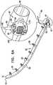
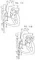
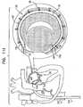
- FIGs. 1-4are schematic illustrations of a system 20 for repairing a dilated atrioventricular valve, such as a mitral valve, in accordance with an application of the present invention.
- System 20comprises an adjustable partial annuloplasty ring 22, shown alone in Figs. 1A and 1B in a non-contracted state, and an anchor deployment manipulator 24, shown alone in Fig. 2 .
- Annuloplasty ring 22comprises a flexible sleeve 26.
- Anchor deployment manipulator 24is advanced into sleeve 26, as shown in Figs. 3 and 4 , and, from within the sleeve, deploys anchors 38 through a wall of the sleeve into cardiac tissue, thereby anchoring the ring around a portion of the valve annulus.
- FIGs. 1A and 1Bare schematic illustration of annuloplasty ring 22 in a non-contracted state, in accordance with respective applications of the present invention.
- Sleeve 26is typically configured to be placed only partially around the valve annulus (i.e., to assume a C-shape), and, once anchored in place, to be contracted so as to circumferentially tighten the valve annulus.
- the ringis configured to be placed entirely around the valve annulus.
- annuloplasty ring 22comprises a flexible elongated contracting member 30 that extends along the ring.
- Annuloplasty ring 22further comprises a contracting mechanism 40, which facilitates contracting of the annuloplasty ring: Contracting mechanism 40 is described in more detail hereinbelow.
- the ringcomprises a plurality of anchors 38, typically between about 5 and about 20 anchors, such as about 10 or about 16 anchors.
- anchors 38are shown prior to their insertion into ring 22, while in Fig. 3 one of the anchors is shown deployed through the wall of sleeve 26, and a second one of the anchors is shown during deployment by anchor deployment manipulator 24. The insertion of the anchors into the sleeve and deployment of the anchors into cardiac tissue is described in detail hereinbelow.
- Flexible sleeve 26may comprise a braided, knitted, or woven mesh or a tubular structure comprising ePTFE.
- the braidcomprises metal and fabric fibers.
- the metal fiberswhich may comprise Nitinol for example, may help define the shape of the sleeve, e.g., hold the sleeve open to provide space for passage and manipulation of deployment manipulator 24 within the sleeve.
- the fabric fibersmay promote tissue growth into the braid.
- the sleeveis somewhat elastic, which gives the sleeve a tendency to longitudinally contract, thereby helping tighten the sleeve.
- the sleevemay be bellows- or accordion-shaped.
- the sleeveis configured to have a tendency to assume a straight shape. This straightness helps the surgeon locate the next site for each subsequent anchor during the implantation procedure, as described hereinbelow with reference to Figs. 11A-I .
- the sleevemay help provide an indication of distance between adjacent anchoring sites.
- the sleeveis configured to have a controllably variable stiffness.
- a somewhat stiff wiremay be placed in the sleeve to provide the stiffness, and subsequently be removed at the conclusion of the implantation procedure when the stiffness is no longer useful.
- Elongated contracting member 30comprises a wire, a ribbon, a rope, or a band, which typically comprises a flexible and/or superelastic material, e.g., nitinol, polyester, stainless steel, or cobalt chrome.
- the wirecomprises a radiopaque material.
- contracting member 30comprises a braided polyester suture (e.g., Ticron).
- contracting member 30is coated with polytetrafluoroethylene (PTFE).
- contracting member 30comprises a plurality of wires that are intertwined to form a rope structure.
- contracting member 30is positioned at least partially within a lumen of the sleeve 26, such as entirely within the lumen (as shown in Figs. 1A-B , 5A-B , 6A , 11H , and 11I ).
- the contracting memberis sewn into the wall of the sleeve, such that the contracting member is alternatingly inside and outside of the sleeve along the length of the sleeve (as shown in Figs. 3 , 13, and 14 ).
- sleeve 26defines an internal channel within which member 30 is positioned (configuration not shown).
- the contracting memberis disposed outside the lumen of the sleeve, such as alongside an outer wall of the sleeve.
- sleeve 26may define an external channel within which member 30 is positioned, or the sleeve may comprise or be shaped so as to define external coupling elements, such as loops or rings (configuration not shown).
- contracting member 30is positioned approximately opposite the anchors.
- contracting mechanism 40comprises a rotatable structure, such as a spool 46.
- the rotatable structureis arranged such that rotation thereof contracts annuloplasty ring 22.
- a first end 47 of contracting member 30is coupled to the spool.
- contracting mechanism 40further comprises a housing 44 that houses the rotatable structure, e.g., the spool.
- Spool 46is positioned in a vicinity of (e.g., within 1 cm of) either a distal end 51 of sleeve 26, as shown in Figs. 1A and 3 , or a proximal end 49 of sleeve 26, as shown in Fig. 1B .
- a second end 53 of contracting member 30is coupled to the sleeve in a vicinity of (e.g., within 1 cm of) the end of the sleeve opposite the end to which the spool is positioned.
- second end 53 of contracting member 30is coupled to the sleeve in a vicinity of proximal end 49 of the sleeve
- the second end of the contracting memberis coupled to the sleeve in a vicinity of distal end 51 of the sleeve.
- Rotation of spool 46winds a portion of the contracting member around the spool, thereby pulling the far end of the ring toward the spool and shortening and tightening the ring.
- spool 46is positioned at an intermediary position along the sleeve, rather than in a vicinity of one of the ends.
- contracting member 30comprises two contracting members, which are respectively connected to the two ends of the sleeve, and both of which are connected to the spool. Rotating the spool contracts both contracting members.
- spool 46is shaped to provide a hole 42 or other coupling mechanism for coupling first end 47 of contracting member 30 to the spool, and thereby to contracting mechanism 40.
- contracting member 30comprises at least one wire (e.g., exactly one wire) that passes through a coupling mechanism of spool 46, in order to couple the wire to the spool.
- the ends of the wireare brought together, and together serve as second end 53 of contracting member 30, and may be coupled to one of the several locations of the sleeve mentioned hereinabove.
- approximately the longitudinal center of the wireserves as first end 47 of the contracting member.
- spool 46is shaped to define a driving interface 48.
- driving interface 48is female.
- the interfacemay be shaped to define a channel which extends through the cylindrical portion of spool 46 from an opening provided by an upper surface 50 of spool 46 to an opening provided by a lower surface 52 of spool 46.
- driving interface 48is shaped so as to define an indentation (e.g., a groove) that does not extend entirely through the cylindrical portion of the spool.
- driving interface 48is male, and defines a protrusion, e.g., a hexagonal head or a head having another shape.
- a distal portion of a rotation tool 80engages spool 46 via driving interface 48 and rotates spool 46 in response to a rotational force applied to the rotation tool.
- the rotational force applied to the rotation toolrotates spool 46 via the portion of the rotation tool that engages driving interface 48 of spool 46.
- Spool 46typically comprises a locking mechanism that prevents rotation of the spool after contracting member 30 has been tightened.
- locking techniquesmay be used that are described with reference to Fig. 4 of above-mentioned US Application 12/341,960 to Cabiri , and/or with reference to Figs. 6B , 7 , and 8 hereinbelow.
- contracting mechanism 40is configured to tighten contracting member 30, crimp the contracting member to hold the contracting member taut, and subsequently cut the excess length of the contracting member.
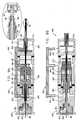
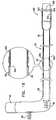
- FIG. 2is a schematic longitudinal cross-sectional illustration of anchor deployment manipulator 24
- Fig. 3is a schematic longitudinal cross-sectional illustration of the anchor deployment manipulator advanced into annuloplasty ring 22
- Fig. 4is a schematic cross-sectional illustration of the anchor deployment manipulator advanced into the annuloplasty ring, taken along section IV-IV of Fig. 3 , in accordance with an application of the present invention.
- Anchor deployment manipulator 24is advanced into a lumen of sleeve 26, and, from within the lumen, deploys anchors 38 through a wall of the sleeve and into cardiac tissue, thereby anchoring the sleeve around a portion of the valve annulus.
- annuloplasty ring 22 and anchor deployment manipulator 24are introduced into the heart via a sheath 104, as described hereinbelow with reference to Figs. 11A-I .
- At least one of anchors 38is deployed from a distal end 60 of deployment manipulator 24 while the distal end is positioned such that a central longitudinal axis 62 through distal end 60 of deployment manipulator 24 forms an angle ⁇ (alpha) of between about 45 and 90 degrees with the wall of sleeve 26 at the point at which the anchor penetrates the wall, such as between about 75 and 90 degrees, e.g., about 90 degrees.
- ⁇alpha
- a line 64schematically illustrates the plane tangential to the wall of the sleeve at the anchor-penetration point.
- This anchor-penetration pointis typically at a portion of the sleeve that extends distally beyond the distal end of outer tube 66 of deployment manipulator 24 (which is described hereinbelow), i.e., that is no longer in contact with the outer surface of outer tube 66.
- all of the anchorsare deployed at such angles, with the possible exception of the first anchor deployed near the distal end of the sleeve.
- At least one of anchors 38is deployed from distal end 60 of deployment manipulator 24 while distal end 60 is positioned such that longitudinal axis 62 through distal end 60 of deployment manipulator 24 forms an angle ⁇ (beta) of between about 45 and 90 degrees (such as between about 75 and 90 degrees, e.g., about 90 degrees) with a line 65 defined by (a) a first point 67 at which the anchor currently being deployed penetrates the wall of the sleeve and (b) a second point 69 at which a most recently previously deployed anchor penetrates the wall of sleeve 26.
- all of the anchorsare deployed at such angles, with the exception of the first anchor deployed near the distal end of the sleeve.
- the anchorsare deployed from distal end 60 of deployment manipulator 24 into the cardiac tissue in a direction parallel to central longitudinal axis 62.
- anchor deployment manipulator 24comprises an outer tube 66 (sometimes referred to herein, including in the claims, as a "deployment manipulator tube”) and an anchor driver 68 which is at least partially positioned within tube 66.
- Anchor driver 68comprises an elongated, flexible shaft 70, having at its distal end a driver head 72. Rotation of the anchor driver screws the anchors into the cardiac tissue.
- Each of anchors 38is shaped so as to define a coupling head 74 and a tissue coupling element 76.
- the anchorsare typically rigid.
- Tissue coupling elements 76may, for example, be helical or spiral in shape (e.g., having the shape of a corkscrew), as shown in the figures, may comprise screws, or may have other shapes.
- Coupling heads 74may be either male (e.g., a hex or square protrusion) or female (e.g., a straight slot, a hex opening, a Phillips opening, or a Robertson opening).
- the anchorsmay comprise staples, clips, spring-loaded anchors, or other tissue anchors described in the references hereinabove in the Background section, or otherwise known in the art.
- anchor deployment manipulator 24 and/or anchors 38are implemented using techniques described hereinbelow with reference to Figs. 20A-E .
- outer tube 66 of deployment manipulator 24is steerable, as known in the catheter art, while for other applications, a separate steerable tube is provided, as described hereinbelow with reference to Fig. 15 or Fig. 16 .
- each of tissue coupling elements 76is shaped so as to define a longitudinal axis 78 (shown in Figs.
- Deployment manipulator 24is configured to deploy tissue coupling element 76 from distal end 60 of the deployment manipulator through the wall of sleeve 26 in a direction parallel to longitudinal axis 78 and parallel to central longitudinal axis 62 through distal end 60 of deployment manipulator 24 (shown in Figs. 2, 3 , and 12-15 ).
- the plurality of anchorsare applied using the deployment manipulator by loading a first one of the anchors onto the anchor driver, and deploying the anchor into the cardiac tissue.
- the anchor driveris withdrawn from the subject's body (typically while leaving outer tube 66 of the deployment manipulator in place in the sleeve), and a second one of the anchors is loaded onto the anchor driver.
- the anchor driveris reintroduced into the outer tube of the deployment manipulator, and the second anchor is deployed. These steps are repeated until all of the anchors have been deployed.
- the entire deployment manipulator, including the anchor driveris removed from the body and subsequently reintroduced after being provided with another anchor.
- the deployment manipulatoris configured to simultaneously hold a plurality of anchors, and to deploy them one at a time (configuration not shown).
- the first anchor 38is deployed most distally in sleeve 26 (generally at or within a few millimeters of a distal end 51 of the sleeve), and each subsequent anchor is deployed more proximally, such that sleeve 26 is gradually pulled off (i.e., withdrawn from) deployment manipulator 24 in a distal direction during the anchoring procedure.
- the deployment manipulatoris moved generally laterally along the cardiac tissue, as shown in Fig. 3 .
- an implant structurecomprising a contracting mechanism, such as contracting mechanism 40.
- the contracting mechanismcomprises a rotatable structure, arranged such that rotation of the rotatable structure contracts the implant structure.
- the implantfurther comprises a longitudinal member, which is coupled to the contracting mechanism.
- a toolsuch as rotation tool 80, is provided for rotating the rotatable structure. The tool is configured to be guided over the longitudinal member, to engage the rotatable structure, and to rotate the rotatable structure in response to a rotational force applied to the tool.
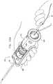
- Figs. 5A-Bare schematic illustrations of rotation tool 80 being used to rotate spool 46 of contracting mechanism 40 of ring 22, in accordance with respective applications of the present invention.
- the implant structurecomprises annuloplasty ring 22.
- Rotation tool 80has a head 82 that is either male (e.g., comprising a screwdriver head, having, such as a slot-head, an Allen-head, a Phillips-head, a Robertson-head, or a hex-head) or female (e.g., comprising a wrench head, having, for example, a square or hex opening), as appropriate for the driving interface provided.
- the rotation toolcomprises a shaft 84, at least a portion of which is flexible.
- the rotation toolis used that is described in above-referenced US Patent Application 12/341,960 , with reference to Fig. 4 thereof.
- anchor driver 68 of deployment manipulator 24serves as rotation tool 80, and is used to rotate the spool, in which case driving interface 48 is appropriately shaped to receive driver head 72 of anchor driver 68.
- contracting member 30is coupled to distal end 51 of sleeve 26, as shown hereinabove in Figs. 1A and 3 .
- Contracting mechanism 40is oriented such that driving interface 48 thereof is accessible from within sleeve 26.
- Rotation tool 80is inserted into sleeve 26, and used to rotate spool 46 via the driving interface.
- anchor driver 68 of deployment manipulator 24serves as rotation tool 80, and is used to rotate the spool, in which case driving interface 48 is appropriately shaped to engage driver head 72 of anchor driver 68. In either case, the sleeve thus serves to guide the rotation tool to driving interface 48.
- an interior surface of the sleeveis tapered near the distal end of the sleeve, to help guide the head 82 of rotation tool 80 to the driving interface.
- anchor deployment manipulator 24is left slightly inserted into proximal end 49 of sleeve 26 after all of anchors 38 have been deployed, in order to facilitate passage of rotation tool 80 into sleeve 26.
- contracting mechanism 40comprises a longitudinal member 86, such as a wire, that is attached to the mechanism and passes out of the body of the subject, typically via sheath 104.
- rotation tool 80is guided over (as shown) the longitudinal member, or alongside the longitudinal member (configuration not shown).
- the longitudinal membercomprises a suture or other highly flexible element.
- the longitudinal membercomprises a tube, through which rotation tool 80 is passed to bring the tool to the driving interface 48.
- longitudinal member 86has a diameter of between 0.1 and 1 mm, such as 0.4 mm.
- longitudinal member 86is looped through contracting mechanism 40, and both ends of the longitudinal member are brought together and extend outside of the subject's body.
- the longitudinal memberis decoupled from the contracting mechanism by releasing one end of the longitudinal member, and pulling on the other end to draw the longitudinal member away from the contracting mechanism.
- contracting mechanism 40is positioned in a vicinity of (e.g., within 1 cm of) distal end 51 of sleeve 26, and access to driving interface 48 is provided from outside sleeve 26, as described with reference to Fig. 5B (in which the contracting mechanism is positioned in a vicinity of proximal end 49 of the sleeve).
- the rotation toolis initially removably attached to the driving interface, prior to the commencement of the implantation procedure, and is subsequently decoupled from the driving interface after spool 46 has been rotated.
- contracting mechanism 40may be positioned in a vicinity of distal end 51 or proximal end 49 of sleeve 26, or at an intermediate location along the sleeve.
- at least a portion of a shaft of the rotation toolis positioned within sheath 104, which is described hereinbelow with reference to Figs. 11A-I .
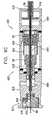
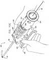
- Figs. 6A and 6Bare schematic isometric and cross-sectional illustrations, respectively, of another configuration of rotation tool 80 being used to rotate spool 46 of contracting mechanism 40 of ring 22, in accordance with an application of the present invention.
- access to driving interface 48is provided from outside sleeve 26.
- Contracting mechanism 40comprises longitudinal member 86 that is attached to the contracting mechanism 40 and passes out of the body of the subject, typically via sheath 104.
- rotation tool 80is guided over longitudinal member 86.
- rotation tool 80comprises one or more tubes that pass over the longitudinal member, as described below.
- longitudinal membercomprises a wire, which may comprise metal. Because the wire is fairly stiff, the wire generally maintains its direction and orientation with respect to contracting mechanism 40. The wire thus readily guides the tubes to the contracting mechanism such that the tubes have a desired orientation and position with respect to the contracting mechanism.
- Longitudinal member 86is removably coupled to contracting mechanism 40, typically to a central portion of upper surface 50 of spool 46.
- a distal portion 88 of longitudinal member 86is shaped so as to define a screw thread 90.
- Distal portion 88is screwed into a threaded opening 92 of upper surface 50, in order to removably couple longitudinal member 86 to contracting mechanism 40.
- the distal portionis initially coupled to the contracting mechanism before annuloplasty ring 22 is placed into an atrium of the patient. As described below, the distal portion is decoupled from the contracting mechanism after spool 46 has been rotated to tighten ring 22.
- distal portion 88comprises a discrete element that is fixed to longitudinal member 86, while for other application, distal portion 88 is integral with longitudinal member 86.
- rotation tool 80comprises an inner (first) tube 98, an intermediate (second) tube 96, and, optionally, an outer (third) tube 94.
- Rotation of each of the tubesis independently controlled, such as using techniques described hereinbelow with reference to Figs. 9A-C and/or 10A-D .
- a distal portion of each of tubes 94, 96, and 98 that enters the patient's bodycomprises braided plastic
- a proximal portion of each of the tubes that does not enter the patient's bodycomprises a hard material, such as metal (not shown).
- the distal and proximal portionsmay have lengths of between 50 and 100 cm and between 50 and 350 cm, respectively.
- Distal-most portions 94D, 96D, and 98D, respectively, of the distal portionstypically comprise a hard material, such as metal, in order to engage other elements, as described immediately below.
- the distal-most portionscomprise separate elements that are coupled to their respective tubes.
- the distal-most portionsmay have lengths of between 1 and 10 mm.
- Intermediate tube 96is configured to rotate spool 46.
- intermediate tube 96(such as distal-most portion 96D thereof) is configured to engage upper surface 50 of spool 46.
- the upper surfacetypically is shaped so as to define one or more indentations 99 (e.g., grooves), in which corresponding protrusions at the distal end of intermediate tube 96 are positioned, such as by gently rotating tube 96 (or all of the tubes) until such engagement occurs.
- indentations 99e.g., grooves
- the radius of intermediate tube 96is approximately equal to the distance of each of the indentations from a center of upper surface 50, so that the protrusions at the distal end of the tube are aligned with the indentations.
- the upper surfacedefines one or more protrusions, which engage indentations on the distal end of tube 96 (configuration not shown). Indentations 99 or the protrusions thus serve as driving interface 48.
- Rotation of intermediate tube 96causes corresponding rotation of spool 46, thereby winding contracting member 30 around the spool, and tightening the contracting member.
- Outer tube 94is configured to prevent rotation of spool housing 44 during rotation of spool 46.
- outer tube 94(such as distal-most portion 94D thereof) is configured to engage an upper surface 160 of spool housing 44.
- the upper surfacetypically is shaped so as to define one or more indentations 162 (e.g., grooves), in which corresponding protrusions at the distal end of outer tube 94 are positioned, such as by gently rotating the tube (or all of the tubes) until such engagement occurs.
- the radius of outer tube 94is approximately equal to the distance of each of the indentations from a center of spool housing 44, so that the protrusions at the distal end of the tube are aligned with the indentations.
- the upper surfacedefines one or more protrusions, which engage indentations on the distal end of tube 94 (configuration not shown).
- outer tube 94is held rotationally stationary, thereby stabilizing spool housing 44 and enabling spool 46 to rotate with respect to housing 44.
- Inner tube 98is configured to decouple longitudinal member 86 from spool 46 after contracting member 30 has been sufficiently wound around the spool, as described above.
- a distal portion of the inner tube(such as distal-most portion 98D thereof) is shaped so as to engage a distal portion of longitudinal member 86, which is typically shaped so as to couple with the distal portion of the inner tube.
- Longitudinal member 86 and spool 46are typically configured such that this unscrewing rotation is in the opposite direction of the rotation of the spool that tightens the contracting member. For example, clockwise rotation of the spool (looking down on the spool) may wind the contracting member around the spool, while counterclockwise rotation of longitudinal member 86 unscrews the longitudinal member from the spool.
- the distal portionmay include a flat portion.
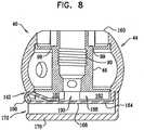
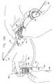
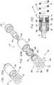
- Fig. 7shows a relationship among individual components of contracting mechanism 40, in accordance with an application of the present invention.
- Contracting mechanism 40is shown as comprising spool housing 44 which defines an upper surface 160 and a recessed portion 176.
- Spool 46is configured to be disposed within housing 44 and defines an upper surface 178, a lower surface 180 and a cylindrical body portion disposed vertically between surfaces 178 and 180.
- Lower surface 180 of spool 46is shaped to define one or more (e.g., a plurality, as shown) recesses 182 which define structural barrier portions 188 of lower surface 180. It is to be noted that any suitable number of recesses 182 may be provided, e.g., between 1 and 10 recesses, circumferentially with respect to lower surface 180 of spool 46.
- spool 46comprises a locking mechanism 164.
- locking mechanism 164is coupled, e.g., welded, at least in part to a lower surface of spool housing 44.
- locking mechanism 164defines a mechanical element having a planar surface that defines slits 184.
- the surface of locking mechanism 164may also be curved, and not planar.
- Locking mechanism 164is shaped to provide a protrusion 166 which projects out of a plane defined by the planar surface of the mechanical element.
- the slitsdefine a depressible portion 168 of locking mechanism 164 that is disposed in communication with and extends toward protrusion 166.
- Depressible portion 168is moveable in response to a force applied thereto by a distal element 70 that extends in a distal direction from distal portion 88 of longitudinal member 86, beyond threaded opening 92 of upper surface 50, as shown in Fig. 6B .
- planar, mechanical element of locking mechanism 164is shown by way of illustration and not limitation and that any suitable mechanical element having or lacking a planar surface but shaped to define at least one protrusion may be used together with locking mechanism 164.
- a cap 170is provided that is shaped so as to define a planar surface and an annular wall having an upper surface 186 that is coupled to, e.g., welded to, a lower surface of spool housing 44.
- the annular wall of cap 170is shaped so as to define a recessed portion 172 of cap 170 that is in alignment with recessed portion 176 of spool housing 44.
- FIG. 6Bshows contracting mechanism 40 in an unlocked state
- Fig. 8shows the contracting mechanism in a locked state.
- protrusion 166 of locking mechanism 164is disposed within recessed portion 172 of cap 170.
- Longitudinal member 86is shaped so as to define a distal force applicator 174 that extends distally, typically beyond screw thread 90.
- the force applicatorextends through spool 46 and pushes against depressible portion 168 of locking mechanism 164.
- the depressible portionis thus pressed downward, as shown in Fig. 6B , freeing protrusion 166 from within a recess 190 defined by structural barrier portions 188 of the lower portion of spool 46.
- protrusion 166is freed from within recessed portion 176 provided by spool housing 44.
- contracting mechanism 40is unlocked, and spool 46 may be rotated with respect to spool housing 44.
- Cap 170functions to restrict distal pushing of depressible portion 168 beyond a desired distance so as to inhibit deformation of locking mechanism 164.
- cap 170also provides an interface between contracting mechanism 40 and the heart tissue. This prevents interference of heart tissue on contracting mechanism 40 during the locking and unlocking thereof. Additionally, cap 170 prevents damage to heart tissue by depressible portion 168 as it is pushed downward.
- protrusion 166is positioned within a recess 190 of spool 46.
- the locked stateis the resting state of locking mechanism 162.
- Depressible portion 168is disposed in a horizontal position, in response to removal of distal force applicator 174 from within spool 46.
- Depressible portion 168has a tendency to assume the horizontal position, as shown, and in the absence of a downward pushing force applied to depressible portion 168 by force applicator 174, depressible portion 168 returns to its horizontal position from its pushed-down state, as shown in Fig. 8 .
- protrusion 166 of locking mechanism 164is removed from recessed portion 172 of cap 170 and is returned within a recess 190 of spool 46 and thereby restricts movement of spool 46 and locks contracting mechanism 40. Additionally, protrusion 166 of locking mechanism 164 returns in part within recessed portion 176 of spool housing 44. Thus, recessed portion 176 of spool housing 44 provides supplemental locking of locking mechanism 164.
- FIGs. 9A-C and 10A-Dare schematic cross-sectional and isometric illustrations, respectively, of a rotation handle 400, in accordance with an application of the present invention.
- rotation handle 400is used for controlling rotation tool 80, and thus the rotational positions of tubes 94, 96, and 98, described hereinabove with reference to Figs. 6A-B .
- rotation handle 400is used to rotate other tubes, such as for other medical applications.
- Rotation handle 400comprises a handle housing 410 and one or more knobs for controlling the rotation of the tubes.
- the housingis typically configured to be coupled to outer tube 94, such that the outer tube cannot rotate with respect to the housing.
- the handlemay comprise a hollow coupling element 412, into which the outer tube is inserted and fixed.
- Intermediate tubes 96 and 98are coupled to other elements of handle 400, as described below.
- handle 400is used with rotation tool 80.
- a proximal portion of longitudinal member 86extends outside the patient's body, such as via sheath 104 (shown, for example, in Figs. 2 , 11C-I , and 12 ).
- Tubes 94, 96, and 98are threaded over this proximal portion of the longitudinal member, such that the longitudinal member is directly within inner tube 98, which is in turn within intermediate tube 96, which is in turn within outer tube 94.
- the proximal end of longitudinal member 86is threaded at least partially through the handle, such as entirely through the length of handle 400, from a distal end 414 thereof to a proximal end 416 thereof.
- Longitudinal member 86is coupled to the handle such that the longitudinal member is longitudinally fixed to the housing (i.e., cannot be withdrawn), but is allowed to rotate with respect to the housing.
- handle 400comprises a longitudinal member coupling assembly 418, for example positioned in a vicinity of proximal end 416 of the housing.
- longitudinal member coupling assembly 418is configured to rotate with respect to the housing, thereby allowing longitudinal member 86 to rotate with respect to the housing.
- longitudinal member coupling assembly 418comprises a lever 452 that is biased by a spring 454 to pivot such that an end of the lever at a central longitudinal axis of handle 400 applies a force in a distal direction.
- the end of the levelis shaped to allow longitudinal member 86 to be advanced toward proximal end 416 of handle 400, while preventing withdrawal of the longitudinal member in a distal direction.
- rotation handle 400comprises an intermediate-tube (second-tube) rotation knob 430 and an inner-tube (first-tube) rotation knob 432.
- intermediate-tube rotation knob 430is positioned closer to distal end 414 of handle 400 than is inner-tube rotation knob 432.
- Intermediate-tube rotation knob 430is coupled to intermediate tube 96 (e.g., using an adhesive), such that rotation of the knob rotates the tube.
- Inner-tube rotation knob 432is coupled to inner tube 98 (e.g., using an adhesive), such that rotation of the knob rotates the tube. The two knobs thus enable convenient rotation of the tubes, either separately or together.
- rotation handle 400further comprises a control knob 434, which, for some applications, is configured to slide longitudinally in distal and proximal directions over knobs 430 and 432.
- a control knob 434When control knob 434 is positioned in a first position (e.g., a first longitudinal position, such as a proximal position, as shown in Figs. 9A and 9B ), an inner surface of the control knob engages both knobs 430 and 432. Rotation of the control knob thus rotates both intermediate-tube rotation knob 430 (and thus intermediate tube 96) and inner-tube rotation knob 432, (and thus inner tube 98). The rotation of intermediate tube 96 rotates spool 46, as described hereinabove with reference to Figs. 6A-B .
- inner tube 98rotates longitudinal member 86 at the same rate as the spool is rotated, such that longitudinal member 86 remains screwed into the spool.
- the inner surface of the control knobis shaped so as to define ridges which matingly engage troughs defined by external surfaces of knobs 430 and 432.
- control knob 434When control knob 434 is positioned in a second position (e.g., a second longitudinal position, such as a distal position, as shown in Fig. 9C ), (a) an inner surface of control knob 434 engages intermediate-tube rotation knob 430 but not inner-tube rotation knob 432, leaving knob 432 free to rotate independently of control knob 434, and (b) an outer surface of control knob 434 engages housing 410, rotationally fixing the control knob, and thus intermediate-tube rotation knob 430, to the housing. Handle 400 thus prevents rotation of intermediate tube 96 and outer tube 94, while allowing rotation of inner tube 98.
- a second positione.g., a second longitudinal position, such as a distal position, as shown in Fig. 9C
- a second positione.g., a second longitudinal position, such as a distal position, as shown in Fig. 9C
- a second positione.g., a second longitudinal position, such as a distal position, as shown
- control knob 434may be shaped so as to define ridges, protrusions 440 (as best seen in Fig. 10D ), teeth, or other engagement surfaces, for engaging housing 410, an inner surface of which may define complementary engagement surfaces, such as troughs.
- Figs. 9A and 9Bwhen in the first position control knob 434 is closer to proximal end 416 of handle 400, as shown in Figs. 9A and 9B , and when in the second position control knob 434 is closer to distal end 414 of handle 400, as shown in Fig. 9C .
- control knob 434when control knob 434 is positioned in the first longitudinal position (such as a proximal position, as shown in Figs. 9A, 9B , and 10A-C ), the control knob at least partially (typically entirely) covers inner-tube rotation knob 432, thereby preventing access to knob 432 by the surgeon.
- control knob 434is subsequently positioned in the second longitudinal position (such as a distal position, as shown in Figs. 9C and 10D )
- the control knobreveals (i.e., no longer covers) inner-tube rotation knob 432.
- the surgeonthus has convenient access to exposed knob 432, as best seen in Fig. 10D .
- Housing 410is also shaped so as to enable such access, as can be seen, for example, in Fig. 10D .
- control knob 434does not slide, and instead assumes the first and second positions in response to a non-sliding motion.
- handle 400comprises one or more springs 460 that spring-load one or more of tubes 94, 96, and 98, pushing the tubes in a distal direction.
- spring-loadingpushes the tubes against the respective elements of contracting mechanism 40, helping the tubes to engage the respective elements of the contracting mechanism, as described hereinabove with reference to Figs. 6A-B .
- rotation handle 400comprises a spring locking mechanism 462, which is configured to assume locking and released states.
- the spring locking mechanismprevents one or more of tubes 94, 96, and 98 from advancing in a distal direction.
- the mechanismmay prevent tubes 94, 96, and 98 from advancing distally by preventing distal movement of coupling element 412, intermediate-tube rotation knob 430, and inner-tube rotation knob 432, respectively. Preventing such distal movement holds the springs in relatively compressed states, and prevents the springs from applying force to the tubes.
- the tubesare more easily coupled to the respective elements of contracting mechanism 40 when the tubes are not spring-loaded.
- spring locking mechanism 462comprises one or more pins 464, such as three pins, which are configured to be inserted into housing 410 (e.g., into respective openings in the housing), and, when so inserted, to block the distal motion of respective elements of the rotation handle, such as coupling element 412, intermediate-tube rotation knob 430, and inner-tube rotation knob 432.
- spring locking mechanism 462does not prevent tubes 94, 96, and 98 from advancing in the distal direction.
- the mechanismmay not prevent distal movement of coupling element 412, intermediate-tube rotation knob 430, and inner-tube rotation knob 432.
- Releasing the tubes and/or these elementsallows springs 460 to expand, thereby pushing the tubes in a distal direction, as best seen in Fig. 9B .
- Such spring-loadingpushes the tubes against the respective elements of contracting mechanism 40, helping the tubes to engage the respective elements of the contracting mechanism, as described hereinabove with reference to Figs. 6A-B .
- the springsdistally advance the tubes 94, 96, and 98 by distally moving coupling element 412, intermediate-tube rotation knob 430, and inner-tube rotation knob 432, respectively, as shown in Fig. 9B .
- Fig. 10Ashows rotation handle 400 after the tubes have been coupled to respective elements of the handle, as described above, and as the surgeon pulls longitudinal member 86 through handle 400 and out of proximal end 416 thereof.
- longitudinal member coupling assembly 418may be provided to prevent withdrawal of the longitudinal member in a distal direction after the longitudinal member has been drawn sufficiently through the handle.
- Fig. 10Aalso shows spring locking mechanism 462 in its locking state.
- Fig. 10Bshows rotation handle 400 after the initial coupling of the tubes to contracting mechanism 40. Because spring locking mechanism 462 is still in its locking state, springs 460 have not yet distally pushed the tubes, so the tubes have not yet fully engaged respective elements of the contracting mechanism.
- Fig. 10Cshows rotation handle 400 after spring locking mechanism 462 has been released to its released state. This release allows springs 460 to distally push the tubes against respective elements of contracting mechanism 40 until the tubes fully engage respective elements of the contracting mechanism.
- Control knob 434is shown in its first (proximal) longitudinal position, in which an inner surface of the control knob engages both knobs 430 and 432 (not visible in Fig. 10C ). Rotation of the control knob thus rotates both intermediate-tube rotation knob 430 (and thus intermediate tube 96) and inner-tube rotation knob 432 (and thus inner tube 98).
- the rotation of intermediate tube 96rotates spool 46, as described hereinabove with reference to Figs. 6A-B .
- the rotation of inner tube 98rotates longitudinal member 86 at the same rate as the spool is rotated, such that longitudinal member 86 remains screwed into the spool.
- Fig. 10Dshows rotation handle 400 after control knob 434 has been is positioned in its second (distal) longitudinal position, in which (a) an inner surface of control knob 434 engages intermediate-tube rotation knob 430 (not visible in Fig. 10D ) but not inner-tube rotation knob 432 (visible in Fig. 10D ), leaving knob 432 free to rotate independently of control knob 434, and (b) an outer surface of control knob 434 engages housing 410, rotationally fixing the control knob, and thus intermediate-tube rotation knob 430, to the housing.
- Handle 400thus prevents rotation of intermediate tube 96 and outer tube 94, while allowing rotation of inner tube 98.
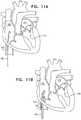
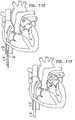
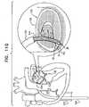
- FIGs. 11A-Iare schematic illustrations of a procedure for implanting annuloplasty ring 22 to repair a mitral valve 130, in accordance with an application of the present invention.
- the procedureis typically performed with the aid of imaging, such as fluoroscopy, transesophageal echo, and/or echocardiography.
- the proceduretypically begins by advancing a semi-rigid guidewire 102 into a right atrium 120 of the patient, as shown in Fig. 11A .
- guidewire 102provides a guide for the subsequent advancement of a sheath 104 therealong and into the right atrium. Once sheath 104 has entered the right atrium, guidewire 102 is retracted from the patient's body.
- Sheath 104typically comprises a 14-20 F sheath, although the size may be selected as appropriate for a given patient.
- Sheath 104is advanced through vasculature into the right atrium using a suitable point of origin typically determined for a given patient. For example:
- sheath 104is advanced through an inferior vena cava 122 of the patient (as shown) and into right atrium 120 using a suitable point of origin typically determined for a given patient.
- Sheath 104is advanced distally until the sheath reaches the interatrial septum.
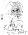
- a resilient needle 106 and a dilatorare advanced through sheath 104 and into the heart.
- the dilatorIn order to advance sheath 104 transseptally into left atrium 124, the dilator is advanced to the septum, and needle 106 is pushed from within the dilator and is allowed to puncture the septum to create an opening that facilitates passage of the dilator and subsequently sheath 104 therethrough and into left atrium 124.
- the dilatoris passed through the hole in the septum created by the needle.
- the dilatoris shaped to define a hollow shaft for passage along needle 106, and the hollow shaft is shaped to define a tapered distal end. This tapered distal end is first advanced through the hole created by needle 106. The hole is enlarged when the gradually increasing diameter of the distal end of the dilator is pushed through the hole in the septum.
- sheath 104The advancement of sheath 104 through the septum and into the left atrium is followed by the extraction of the dilator and needle 106 from within sheath 104, as shown in Fig. 11E .
- annuloplasty ring 22(with anchor deployment manipulator 24 therein) is advanced through sheath 104 into left atrium 124.
- distal end 51 of sleeve 26is positioned in a vicinity of a left fibrous trigone 142 of an annulus 140 of mitral valve 130.
- distal end 51 of sleeve 26is shown schematically in the cross-sectional view of the heart, although left trigone 142 is in reality not located in the shown cross-sectional plane, but rather out of the page closer to the viewer.
- the tipis positioned in a vicinity of a right fibrous trigone 144 of the mitral valve (configuration not shown).
- the distal tip of the sleeveis not positioned in the vicinity of either of the trigones, but is instead positioned elsewhere in a vicinity of the mitral valve, such as in a vicinity of the anterior or posterior commissure.
- outer tube 66 of anchor deployment manipulator 24is steerable, as is known in the catheter art, while for other applications, a separate steerable tube is provided, as described hereinbelow with reference to Fig. 15 and Fig. 16 .
- the steering functionalitytypically allows the area near the distal end of the deployment manipulator to be positioned with six degrees of freedom.
- deployment manipulator 24is repositioned along annulus 140 to another site selected for deployment of a second anchor 38.
- the first anchoris deployed most distally in the sleeve (generally at or within a few millimeters of the distal tip of the sleeve), and each subsequent anchor is deployed more proximally, such that the sleeve is gradually pulled off (i.e., withdrawn from) the deployment manipulator in a distal direction during the anchoring procedure.
- the already-deployed first anchor 38holds the anchored end of sleeve 26 in place, so that the sleeve is drawn from the site of the first anchor towards the site of the second anchor.
- the deployment manipulatoris moved generally laterally along the cardiac tissue, as shown in Fig. 11H .
- Deployment manipulator 24deploys the second anchor through the wall of the sleeve into cardiac tissue at the second site.
- the portion of sleeve 26 therebetweenmay remain tubular in shape, or may become flattened, which may help reduce any interference of the ring with blood flow.
- anchor driver 68is withdrawn from the subject's body via sheath 104 (typically while leaving outer tube 66 of the deployment manipulator in place in the sleeve), provided with an additional anchor, and then reintroduced into the subject's body and into the outer tube.
- the entire deployment manipulator, including the anchor driveris removed from the body and subsequently reintroduced upon being provided with another anchor.
- deployment manipulator 24is configured to simultaneously hold a plurality of anchors, and to deploy them one at a time at the selected sites.
- the deployment manipulatoris repositioned along the annulus to additional sites, at which respective anchors are deployed, until the last anchor is deployed in a vicinity of right fibrous trigone 144 (or left fibrous trigone 142 if the anchoring began at the right trigone).
- the last anchoris not deployed in the vicinity of a trigone, but is instead deployed elsewhere in a vicinity of the mitral valve, such as in a vicinity of the anterior or posterior commissure.
- rotation tool 80 or anchor driver 68 of deployment manipulator 24is used to rotate spool 46 of contracting mechanism 40, in order to tighten ring 22.
- rotation handle 400is used to tighten the ring, such as described hereinabove with reference to Figs. 9A-C and/or 10A-D .
- another techniqueis used to tighten the ring, such as described hereinabove.
- sleeve 26is filled with a material (e.g., polyester, polytetrafluoroethylene (PTFE), polyethylene terephthalate (PET), or expanded polytetrafluoroethylene (ePTFE)) after being implanted.
- a materiale.g., polyester, polytetrafluoroethylene (PTFE), polyethylene terephthalate (PET), or expanded polytetrafluoroethylene (ePTFE)
- the materialis packed within at least a portion, e.g., 50%, 75%, or 100%, of the lumen of sleeve 26.
- the filler materialfunctions to prevent (1) formation within the lumen of sleeve 26 of clots or (2) introduction of foreign material into the lumen which could obstruct the sliding movement of contracting member 30.
- proximal end 49 of sleeve 26is closed upon completion of the implantation procedure.
- the proximal end of the sleevemay have a natural tendency to close when not held open by deployment manipulator 24.
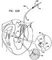
- Fig. 12is a schematic illustration of the deployment of one of anchors 38 into cardiac tissue, in accordance with an application of the present invention.
- one or more (such as all) of anchors 38are deployed from left atrium 124, through tissue of the atrial wall, and into tissue of an upper region of the ventricular wall 150 near the atrium. Because the tissue of the upper region of ventricular wall is thicker than that of the atrial wall, deploying the anchors into the upper region of the ventricular wall generally provides more secure anchoring. In addition, because the anchors are not deployed laterally through the atrial wall, the risk of perforating the atrial wall is reduced.
- Annuloplasty ring 22may be advanced toward annulus 140 in any suitable procedure, e.g., a transcatheter procedure, a percutaneous procedure, a minimally invasive procedure, or an open heart procedure (in which case one or more elements of system 20 are typically rigid). Regardless of the approach, the procedure typically includes the techniques described hereinabove with reference to Figs. 11G-I and 12 .
- a rotation tool or anchor driver 68 of deployment manipulator 24is reintroduced into the heart and used to contract or relax annuloplasty ring 22.
- Fig. 13is a schematic illustration of system 10 comprising a flexible pusher element 200, in accordance with an alternative arrangement. Pusher element 200 aids with accurately positioning successive anchors 38 during an implantation procedure, such as described hereinabove with reference to Figs. 11H and 11I .
- pusher element 200is positioned partially within tube 66 of deployment manipulator 24 such that a distal portion 204 of pusher element 200 extends distally out of tube 66, through an opening 206 in a vicinity of a distal end of the tube (e.g., that is within 3 mm of the distal end, such as within 2 mm of the distal end).
- a proximal portion 202 of pusher element 200passes through outer tube 66 from opening 206 to the proximal end of tube 66. Opening 206 is provided either through a wall of the tube (as shown in Fig. 13 ), or through the distal end of the tube (configuration not shown).
- pusher element 200is positioned within sleeve 26, but outside of tube 66 (configuration not shown).
- the pusher elementis elongated, and is as least as long as sleeve 26.
- Pusher element 200helps move the distal end of deployment manipulator 24 from a first site of the annulus at which the deployment manipulator has already deployed a first anchor (e.g., anchor 38A in Fig. 13 ) to a second site for deployment of a second anchor (e.g., anchor 38B), in a direction indicated schematically by an arrow 210.
- Pusher element 200is pushed distally out of opening 206 of tube 66, so that a distal end 212 of pusher element 200 engages and pushes against an interior surface of sleeve 26, in a direction indicated schematically by an arrow 214.
- the interior surface of the sleevemay be distal end 51 of the sleeve (as shown), or the wall of the sleeve at a location between distal end 51 and opening 206 (not shown).
- the distal end of deployment manipulator 24moves in the opposite direction, i.e., as indicated by arrow 210, toward a subsequent anchoring site.
- the movement in the direction of arrow 210is generally along a line or curve defined by the portion of pusher element 200 already extended between the anchors that have already been deployed.
- pusher element 200is extended respective distances through opening 206, each of which distances is successively greater.
- the pusher elementis pulled back in a proximal direction, and again extended a desired distance in a distal direction, such that the pusher element pushes again the wall of the sleeve (at a different location on the wall for each successive relocation of deployment manipulator 24).
- the pusher elementmay also help control the distance between adjacent anchoring sites, because they surgeon may push the pusher element a known distance after deploying each anchor.
- Pusher element 200typically comprises a strip, wire, ribbon, or band, and has a cross-section that is circular, elliptical, or rectangular.
- Pusher element 200typically comprises a flexible and/or superelastic material, such as a metal such as nitinol, stainless steel, or cobalt chrome.
- Distal end 212 of pusher element 200is dull, so that it does not penetrate sleeve 26. For example, the distal end may be folded back, as shown in Fig. 13 .
- Fig. 14is a schematic illustration of a pusher tube 250 applied to proximal end 49 of sleeve 26, in accordance with an application of the present invention.
- outer tube 66is removably positioned partially within the lumen of sleeve 26, such that outer tube 66 extends out of proximal end 49 of sleeve 26 (proximal end 49 can be seen in Fig. 1B ).
- Pusher tube 250is configured to pass over outer tube 66, such that a distal end of the pusher tube comes in contact with proximal end 49 of sleeve 26.
- the pusher tube 250is held in place against proximal end 49 of sleeve 26, typically by an external control handle, such as external control handle 346, described hereinbelow with reference to Fig. 17 , or external control handle 490, described hereinbelow with reference to Fig. 19 .
- an external control handlesuch as external control handle 346, described hereinbelow with reference to Fig. 17 , or external control handle 490, described hereinbelow with reference to Fig. 19 .
- pusher tube 250pushes sleeve 26 distally with respect to outer tube 66, helping withdraw the sleeve from the outer tube.
- the wall of sleeve 26might snag on outer tube 66 (as mentioned above, the sleeve may comprise braided or woven fabric). In addition, if such snagging occurs, gentle pushing with the pusher tube in the distal direction may help free the snag.
- the techniques of this applicationare practiced in combination with those of the application described hereinbelow with reference to Fig. 17 .
- Fig. 15is a schematic illustration of system 10 comprising a steerable tube 300, in accordance with an application of the present invention.
- outer tube 66 of deployment manipulator 24is not steerable. Instead, to provide steering functionality, deployment manipulator 24 comprises a separate steering tube 300, which is positioned around at least a portion of outer tube 66.
- Outer tube 66because it does not provide this steering functionality, may have a smaller diameter than in the application described hereinabove with reference to Fig. 3 . Because outer tube 66 has a smaller diameter, sleeve 26 may also have a smaller diameter than in the application described hereinabove with reference to Fig. 3 .
- system 10typically comprises contracting member 30, for clarity of illustration the contracting member is not shown in the figure.
- Fig. 16is a schematic illustration of system 10 comprising a steerable tube 320, in accordance with an application of the present invention.
- outer tube 66 of deployment manipulator 24is not steerable.
- Steering functionalityis instead provided by separate steering tube 320, which is positioned around at least a portion of shaft 70 of anchor driver 68, and within outer tube 66.
- the techniques of this applicationare practiced in combination with those of the application described hereinabove with reference to Fig. 14 .
- system 10typically comprises contracting member 30, for clarity of illustration the contracting member is not shown in the figure.
- Fig. 17is a schematic illustration of system 10 comprising a pulling wire 340, in accordance with an application of the present invention.
- a distal portion 342 of pulling wire 340is coupled to proximal end 49 of sleeve 26, such as by passing through one or more holes near the proximal end.
- One or more proximal portions 344 of the pulling wireare coupled to an external control handle 346 of system 10, which is manipulated by the surgeon outside of the subject's body.
- External control handle 346is coupled to a proximal portion of outer tube 66, such as a proximal end of the outer tube.
- a portion of deployment manipulator 24(e.g., a portion of outer tube 66) which is never inserted in sleeve 26 comprises one or more coupling elements 348, such as loops or tubes, through which pulling wire 340 passes in order to hold the pulling wire close to the external surface of the deployment manipulator.
- coupling elements 348such as loops or tubes, through which pulling wire 340 passes in order to hold the pulling wire close to the external surface of the deployment manipulator.
- system 10typically comprises contracting member 30, for clarity of illustration the contracting member is not shown in the figure.
- Pulling wire 340holds sleeve 26 surrounding deployment manipulator 24.
- the pulling wireis released in a distal direction as sleeve 26 is withdrawn from outer tube 66 of deployment manipulator 24 in a distal direction.
- the release of the sleeveallows the sleeve to gradually be withdrawn from the outer tube 66 of deployment manipulator 24, in a controlled manner.
- Fig. 17the sleeve is shown partially withdrawn from outer tube 66, including the portion of the sleeve through which one of anchors 38 has been deployed.
- control handle 346is configured to release pulling wire 340 incrementally in the distal direction, such that each time the wire is further released by respective set distances (typically, the distances are equal to one another).
- the sleeveis withdrawn from outer tube 66 of the deployment manipulator by this set distance (or respective distances), and subsequently-deployed anchors are approximately this set distance (or respective set distances) apart from one another.
- the set distancesmay be between 2 mm and 15 mm, such as 4.5 mm
- the handlecomprises a control ring 350 that is coupled to proximal portions 344 of the wire, and removably engages slots 352 on the handle that are spaced apart by this set distance.
- control handle 346is configured to allow control ring 350 to move only in the distal direction during a surgical procedure.
- one end of the wiremay be cut or released, and the wire detached from the sleeve by pulling on the other end of the wire.
- Figs. 18A and 18Bare schematic illustrations of another configuration of pusher tube 250, described hereinabove with reference to Fig. 14 , in accordance with an application of the present invention.
- pusher tube 250passes over outer tube 66, and pushes gently in a distal direction on proximal end 49 of sleeve 26.
- the pusher tubeis held in place against proximal end 49 of sleeve 26, typically by an external control handle, such as external control handle 346, described hereinabove with reference to Fig. 17 .
- pusher tube 250pushes sleeve 26 distally with respect to outer tube 66, helping withdraw the sleeve from the outer tube. If the pusher tube were not provided, the wall of sleeve 26 might snag on outer tube 66 (as mentioned above, the sleeve may comprise braided or woven fabric). In addition, if such snagging occurs, gentle pushing with the pusher tube in the distal direction may help free the snag.
- pusher tube 250comprises one or more coupling elements 456 (such as exactly one coupling element or exactly two coupling elements).
- the coupling elementsare configured to removably couple proximal end 49 of sleeve 26 to a distal end 458 of pusher tube 250, thereby allowing sleeve 26 from moving distally with respect to outer tube 66 of deployment manipulator 24 only to the extent that pusher tube 250 is released in the distal direction, such as using external control handle 490, described hereinbelow with reference to Fig. 19 .
- coupling elements 456have a natural tendency to flex inwards (toward a central longitudinal axis of sleeve 26 that passes through the proximal end of the sleeve).
- Outer tube 66when positioned within the sleeve in a vicinity of the coupling elements, pushes the coupling elements outwards (away from the central longitudinal axis), causing the coupling elements to engage the sleeve.
- the coupling elementsmay be curved to define outwardly-directed ends that push against or pierce the sleeve. Such pushing against or piercing engages the sleeve, which, as mentioned above, may comprise braided or woven fabric.
- Fig. 18Bshows sleeve 26 released from coupling elements 456.
- Proximal withdrawal of outer tube 66 from sleeve 26allows coupling elements 456 to assume their natural inwardly-flexed position, thereby releasing sleeve 26 from the coupling elements, and decoupling the sleeve from the pusher tube.
- sleeve 26is gradually pulled off (i.e., withdrawn from) deployment manipulator 24, including outer tube 66, in a distal direction during the anchoring procedure.
- Outer tube 66 of deployment manipulator 24is proximally withdrawn completely from the sleeve at the conclusion of the anchoring procedure. The flexing of the coupling elements releases the sleeve at the conclusion of the procedure.
- Fig. 19is a schematic illustration of system 10 comprising an external control handle 490, in accordance with an application of the present invention.
- External control handle 490is configured to be used with pusher tube 250, as described hereinabove with reference to Figs. 14 and/or 18A-B.
- the handleis manipulated by the surgeon outside of the subject's body.
- External control handle 490is coupled to a proximal portion of outer tube 66, such a proximal end of the outer tube.
- coupling elements 456 of pusher tube 250couple proximal end 49 of sleeve 26 to distal end 458 of pusher tube 250, as described hereinabove with reference to Figs. 18A-B (proximal end 49 can be seen in Fig. 18B ).
- a proximal end of pusher tube 250is coupled to handle 490.
- system 10typically comprises contracting member 30, for clarity of illustration the contracting member is not shown in the figure.
- External control handle 490is configured to release pusher tube 250 in a distal direction as sleeve 26 is withdrawn from outer tube 66 of deployment manipulator 24.
- the release of pusher tube 250releases sleeve 26, and allows the sleeve to gradually be withdrawn from outer tube 66, in a controlled manner.
- Fig. 19the sleeve is shown partially withdrawn from outer tube 66, including the portion of the sleeve through which one of anchors 38 has been deployed.
- control handle 490is configured to release pusher tube 250 incrementally in the distal direction, such that each time the pusher tube is further released by respective set distances (typically, the distances are equal to one another).
- the sleeveis withdrawn from outer tube 66 of the deployment manipulator by this set distance (or respective distances), and subsequently-deployed anchors are approximately this set distance (or respective distances) apart from one another.
- the set distancesmay be between 2 mm and 15 mm, such as 4.5 mm.
- the handlecomprises control ring 350 that is coupled to a proximal end of pusher tube 250, and removably engages slots 352 on the handle that are spaced apart by this set distance.
- control handle 490is configured to allow control ring 350 to move only in the distal direction during a surgical procedure.
- outer tube 66 of deployment manipulator 24is proximally withdrawn completely from the sleeve, thereby causing the coupling elements to release the sleeve, such as described hereinabove with reference to Fig. 18B .
- annuloplasty ring 22has been described hereinabove as comprising a partial annuloplasty ring, for some applications of the present invention, the ring instead comprises a full annuloplasty ring.
- Figs. 20A-Eare schematic cross-sectional and isometric illustrations of a configuration of driver head 72 of anchor driver 68, in accordance with an application of the present invention.
- Anchor driver 68is described hereinabove, for example, with reference to Fig. 2 .
- Driver head 72comprises an inner mating component 470, which is coupled to a distal end 472 of flexible shaft 70, such as by welding, such that inner mating component 470 is rotationally fixed to shaft 70.
- innermeans closer to a longitudinal axis 473 of driver head 72.
- a distal end of inner mating component 470is shaped so as to define one or more (e.g., two) mechanical coupling elements, such as protrusions 474.
- Coupling head 74 of anchor 38is shaped so as to define corresponding mating elements, such as slots 476, also shown in Fig. 20B .
- coupling head 74is removably coupled to inner mating component 470 by the coupling and mating elements.
- Driver head 72further comprises an outer element 478, which at least partially surrounds inner mating component 470 and extends in a distal direction beyond a distal end of inner mating component 470.
- outer element 478means further from longitudinal axis 473 of driver head 72.
- outer element 478is free to rotate with respect to inner mating component 470.
- Outer element 478is typically longitudinally fixed to the inner mating component.
- the inner mating componentmay be shaped so as to define at least one lateral protrusion 480, and the outer element may be shaped to define at least one corresponding recess 482.
- one or more of inner mating component 470, distal end 472 of flexible shaft 70, and outer element 478are welded together, or comprise a single element.
- An outer surface of coupling head 74 of anchor 38is typically shaped so as to define a screw thread 484.
- the screw threadis initially screwed into a flexible ring 486 that is coupled to an inner surface of outer element 478.
- the ringis sized to tightly engage the screw thread.
- the ringmay comprise, for example, silicone, rubber, or a springy metal.
- a distal portion of coupling head 74(such as the portion that defines screw thread 484) is conical.
- driver head 72 and anchor 38thus enables the anchor to self-disconnect from the driver head.
- anchor 38is coupled to driver head 72 (typically during manufacture) by:
- repair chords 510function as artificial chordae tendineae, and comprise one or more longitudinal members 520 and 522, e.g., sutures, wires, or elongate tensioning coils, which are coupled at respective first end portions thereof to a contracting mechanism 512. Respective second end portions of the longitudinal members are coupled (e.g., tied, sutured, clipped, or otherwise fastened) to a second portion of tissue which faces and surrounds the ventricle, such as a leaflet 552 of an atrioventricular valve 554 (e.g., a mitral valve or a tricuspid valve).
- atrioventricular valve 554e.g., a mitral valve or a tricuspid valve
- Longitudinal members 520 and 522are knotted together using at least one suture knot 523, and excess portions of longitudinal members 520 and 522 are cut away from the knot.
- any suitable anchormay be used instead of the knot.
- longitudinal member 520may comprise a male clip at its free end and longitudinal member 522 may comprise a female clip at its free end.
- longitudinal members 520 and 522are clipped at their free ends to the leaflet.
- anchors or clipsmay be used that are described in US Patent Application 12/548,991, filed August 27, 2009 , published as US2010161042 , such as with reference to one or more of Figs. 9A-18D and 22A-23I thereof.
- Implant structure 500comprises a contracting mechanism assembly 514, which comprises contracting mechanism 512 and a tissue anchor 550.
- the tissue anchorfacilitates implantation of the contracting mechanism assembly in a first portion of tissue of the heart which faces and surrounds the ventricular lumen, such as a papillary muscle 518.
- Tissue anchor 550is shown as a helical anchor by way of illustration and not limitation, and may comprise staples, clips, spring-loaded anchors, or other tissue anchors known in the art.
- contracting mechanism assembly 514does not include tissue anchor 50 and is, instead, sutured to a portion of tissue of a ventricle wall which faces a ventricular lumen of a heart of a patient.
- contracting mechanism 512comprises a rotatable structure, such as a spool (not visible in Fig. 21 , but typically similar to spool 46, described hereinabove with reference to Figs. 5A-B , 6A-B , 7 , and 8 ), and, typically, a housing 516, which houses the spool. First end portions of the longitudinal members are coupled to contracting mechanism 512, typically to spool 46.
- Implant structure 500comprises one or more longitudinal members 86, which are coupled to contracting mechanism 512, such as to housing 516 or to the spool.
- a rotation tool 530is configured to pass over longitudinal members 86, engage the spool of contracting mechanism 512, and rotate the spool, thereby tightening the contracting mechanism, and shortening and tensioning longitudinal members 520 and 522.
- implant structure 500utilizes techniques described hereinabove with reference to Figs. 5A-B , 6A-B , 7 , 8 , 9A-C , and/or 10A-D .
- implant structure 500utilizes techniques described in US Patent Application 12/548,991, filed August 27, 2009 , published as US2010161042 , such as with reference to one or more of Figs. 3-18D and 22A-23I thereof.
- FIGS. 22A and 22Bare schematic illustrations of another implant structure 600 comprising repair chords 510.
- repair chords 510are used to adjust a distance between two portions of the ventricular wall.
- Fig. 22Ashows implant structure 600 comprising contracting mechanism assembly 514 implanted at a first portion 620 of heart tissue which faces and surrounds the left ventricle of the heart.
- the free ends of longitudinal members 520 and 522are coupled to a second portion 622 of heart tissue which faces and surrounds the left ventricle, e.g., at the septum, by way of illustration and not limitation.
- the free ends of longitudinal members 520 and 522are coupled to the heart tissue using any suitable attachment means 602, e.g., sutures, knotting, or tissue anchors such as helical anchors.
- Implant structure 600comprises contracting mechanism assembly 514, described hereinabove with reference to Fig. 20 .
- Implant structure 600comprises one or more longitudinal members 86, which are coupled to contracting mechanism 512, such as to housing 516 or to the spool.
- Rotation tool 530is configured to pass over longitudinal members 86, engage the spool of contracting mechanism 512, and rotate the spool, thereby tightening the contracting mechanism, and shortening and tensioning longitudinal members 520 and 522.
- first and second portions 620 and 622 of the heart tissueare pulled toward one another. Consequently, the dimensions of the heart wall are restored to physiological dimensions, and the leaflets are drawn toward one another.
- Fig. 22Bshows implant structure 700 for adjusting a distance between two portions of a heart wall of the left ventricle of the patient.
- Longitudinal members 520 and 522are coupled at first portions thereof to a rotatable structure, e.g., a spool, of contracting mechanism 512.
- Respective free ends of each member 520 and 522are coupled to opposing first and second portions of the heart wall which faces and surrounds the ventricular lumen of the heart.
- the free end of longitudinal member 522is coupled to first implantation site using a first helical anchor 750 by way of illustration and not limitation.
- the free end of longitudinal member 522is coupled to the first implantation site using sutures, knots, or any tissue anchor known in the art.
- the free end of longitudinal member 520is coupled to a second implantation site using a second helical anchor 750 by way of illustration and not limitation.
- the free end of longitudinal member 520is coupled to the second implantation site using sutures, knots, or any tissue anchor known in the art.
- contracting mechanism 512is disposed between longitudinal members 520 and 522 and is not directly coupled to heart tissue.
- rotation tool 530is passed over longitudinal members 86, and used to rotate the spool of contracting mechanism 512, such as described hereinabove.
- the spool of contracting mechanism 512is rotated in order to adjust a distance between the first and second implantation sites. Responsively, the first and second portions of the ventricle wall are drawn together. Consequently, the dimensions of the heart wall are restored to physiological dimensions, and the leaflets are drawn toward one another.
- implant structure 500utilizes techniques described hereinabove with reference to Figs.
- implant structure 500utilizes techniques described in US-A-2010/0161042 Patent Application 12/548,991, filed August 27, 2009 , such as with reference to one or more of Figs. 19-21 thereof.
- Fig. 23is a schematic illustration of another configuration of contracting mechanism 40 and an implant structure 800, in accordance with an application of the present invention.
- contracting mechanism 40is used to adjust a length or circumference of implant structure 800, which may comprise, for example, a partial or a full annuloplasty ring, such as ring 22, or another implant structure.
- a first rotatable structure 810is shaped so as to define a pinion 812, and a first portion 813 of implant structure 800 is shaped so as to define a rack 814.
- first and second rotatable structures 810 and 816are maintained at an appropriate distance from each other using a housing or bracket.
- the housing or bracketis not shown in the figure, because the housing or bracket is typically positioned on the further side of the rotatable structures that is not visible in the figure.
- the housing or bracketmay connect the axels of the rotatable structures on the sides thereof opposite the sides shown in Fig. 23 .
- second rotatable structure 816is not provided, and first rotatable structure 810 is coupled directly to second portion 820 of implant structure 800.
- implant structure 800comprises a full band, such as a full annuloplasty ring
- first and second portions 813 and 820 of implant structure 800are opposite ends of the same continuous structure.
- implant structurecomprises a partial band, such as a partial annuloplasty ring
- the respective portions of first and second portions 813 and 820are coupled near respective ends of a sleeve, or themselves define the ring.
- Implant structure 800comprises longitudinal member 86, which is coupled to contracting mechanism 40.
- Rotation tool 80is provided for rotating first rotatable structure 810.
- the toolis configured to be guided over the longitudinal member, to engage the rotatable structure, and to rotate the rotatable structure in response to a rotational force applied to the tool, such as using techniques described hereinabove with reference to Figs. 5A-B , 6A-B , 7 , 8 , 9A-C , and/or 10A-D .
- Valve prosthesis assembly 900comprises a prosthetic heart valve 910 that is couplable to a base ring 922.
- Prosthetic heart valve 910is used to replace a native diseased heart valve.
- Valve 910comprises a plurality of artificial leaflets 930, which comprise a pliant material.
- Valve 910may implement techniques known in the artificial valve art, such as described, for example, in US Patent Application Publication 2007/0255400 to Parravicini et al. , US Patent Application Publication 2004/0122514 to Fogarty et al. , US Patent Application Publication 2007/0162111 to Fukamachi et al. , and/or US Patent Application Publication 2008/0004697 to Lichtenstein et al.
- Valve 910further comprises an annular base 932, to which artificial leaflets 930 are coupled.
- Annular base 932is configured to be couplable to base ring 922 during an implantation procedure.
- base ring 922may comprise one or more coupling elements 934, such as clips or magnets, which are configured to be coupled to corresponding coupling elements on a lower surface of annular base 932 (not visible in the figures).
- annular base 932may be configured to be placed within the opening defined by base ring 922, as shown in Fig. 24A .
- the base ringis tightened around the annular base, as shown in Fig. 24B , typically using one or more of the techniques described hereinabove for contracting implant structures.
- valve prosthesis assembly 900such as annular base 932 thereof, is configured to push and hold open the intact diseased native leaflets.
- Base ring 922implements one or more of the techniques of annuloplasty ring 22 described hereinabove.
- base ring 922may be coupled to the annulus of the native diseased valve using the anchoring techniques described hereinabove.
- base ring 922typically comprises a rotatable structure 936, such as a spool, which is typically implemented using techniques described herein.
- the rotatable structureis arranged such that rotation thereof contracts base ring 922, typically using techniques described herein.
- Such tighteningmay serve to couple base ring 922 to annular base 932, as shown in Fig. 24B .
- such tighteningsets the desired dimensions of the base ring, in order to align the coupling elements of the base ring with those of valve 910, thereby enabling tight coupling, such as for the applications described with reference to Fig. 25 .
- base ring 922comprises a partial ring, as shown in Fig. 25
- the base ringcomprises a full ring, as shown in Figs. 24A-B .
- Valve prosthesis assembly 900is typically implanted in a minimally invasive transcatheter or percutaneous procedure. The procedure begins with the introduction and implantation of base ring 922 into the heart, such as using techniques for implanting annuloplasty ring 22, described hereinabove with reference to Figs. 1 IA-I. Prosthetic heart valve 910 is subsequently introduced into the heart and coupled to base ring 922, as described above. Valve prosthesis assembly 900 is typically used for replacement of a diseased native mitral valve, aortic valve, tricuspid valve, or pulmonary valve.
- system 20is used to treat an atrioventricular valve other than the mitral valve, i.e., the tricuspid valve.
- annuloplasty ring 22 and other components of system 20 described hereinabove as being placed in the left atriumare instead placed in the right atrium.
- annuloplasty ring 22is described hereinabove as being placed in an atrium, for some application the ring is instead placed in either the left or right ventricle.
Landscapes
- Health & Medical Sciences (AREA)
- Cardiology (AREA)
- Life Sciences & Earth Sciences (AREA)
- General Health & Medical Sciences (AREA)
- Public Health (AREA)
- Biomedical Technology (AREA)
- Heart & Thoracic Surgery (AREA)
- Engineering & Computer Science (AREA)
- Animal Behavior & Ethology (AREA)
- Veterinary Medicine (AREA)
- Surgery (AREA)
- Transplantation (AREA)
- Oral & Maxillofacial Surgery (AREA)
- Vascular Medicine (AREA)
- Nuclear Medicine, Radiotherapy & Molecular Imaging (AREA)
- Medical Informatics (AREA)
- Molecular Biology (AREA)
- Rheumatology (AREA)
- Prostheses (AREA)
- Surgical Instruments (AREA)
Description
- Some applications of the present invention relate in general to valve repair, and more specifically to repair of an atrioventricular valve of a patient.
- Ischemic heart disease causes mitral regurgitation by the combination of ischemic dysfunction of the papillary muscles, and the dilatation of the left ventricle that is present in ischemic heart disease, with the subsequent displacement of the papillary muscles and the dilatation of the mitral valve annulus.
- Dilation of the annulus of the mitral valve prevents the valve leaflets from fully coapting when the valve is closed. Mitral regurgitation of blood from the left ventricle into the left atrium results in increased total stroke volume and decreased cardiac output, and ultimate weakening of the left ventricle secondary to a volume overload and a pressure overload of the left atrium.
US-A-2007/055206 discloses devices comprising a shaft defining a lumen for housing at least one anchor therein (the anchor having an eyelet) and a mechanism for deploying the anchor distally from the lumen, wherein the inner diameter of the lumen is the same size or smaller than the diameter of the eyelet of the anchor to be disposed therein when the anchor is in an expanded configuration.US-A-2007/118151 discloses a method of repairing a cardiac valve, comprising introducing a catheter through a patient's vasculature into the patient's heart; advancing a distal end of the catheter proximate a leaflet of a cardiac valve of the patient; using the catheter to direct a first portion of a filament through the leaflet to capture the leaflet; and applying tension to the filament to adjust the function of the cardiac valve.US-A- 2007/0080188 describes systems and methods for securing tissue including the annulus of a mitral valve. The systems and methods may employ catheter based techniques and devices to plicate tissue and perform an annuloplasty. Magnets may be used for guidance in deploying fasteners from a catheter. The fasteners are cinched with a flexible tensile member.US-B-6619291 describes a minimally invasive method of performing annuloplasty. A method for performing a procedure on a mitral valve of a heart includes inserting an implant into a left ventricle and orienting the implant in the left ventricle substantially below the mitral valve. The implant and tissue around the mitral valve are connected and tension is provided to the implant, in one application, in order to substantially reduce an arc length associated with the mitral valve. In another application, the implant is inserted into the left ventricle through the aorta and the aortic valve.US-A-2006/0241656 describes devices, systems and methods for facilitating positioning of a cardiac valve annulus treatment device, thus enhancing treatment of the annulus. Methods generally involve advancing an anchor delivery device through vasculature of the patient to a location in the heart for treating the valve annulus, contacting the anchor delivery device with a length of the valve annulus, delivering a plurality of coupled anchors from the anchor delivery device to secure the anchors to the annulus, and drawing the anchors together to circumferentially tighten the valve annulus. Devices generally include an elongate catheter having at least one tensioning member and at least one tensioning actuator for deforming a distal portion of the catheter to help it conform to a valve annulus. The catheter device may be used to navigate a subannular space below a mitral valve to facilitate positioning of an anchor delivery device.US-A-2005/187613 describes systems and methods to introduce and deploy prosthesis into a blood vessel or hollow body organ by intra-vascular access. The prosthesis is secured in place by fasteners which are implanted by an applier that is also deployed by intra-vascular access. The applier is configured to permit controlled, selective release of the fastener in a step that is independent of the step of implantation.US Patent Application Publication 2006/0025787 to Morales et al. describes methods and devices that provide constriction of a heart valve annulus to treat cardiac valve regurgitation and other conditions. Applications typically include a device for attaching a cinching or tightening apparatus to a heart valve annulus to reduce the circumference of the annulus, thus reducing valve regurgitation. Tightening devices may include multiple tethered clips, multiple untethered crimping clips, stabilizing devices, visualization devices, and the like. In one application, a plurality of tethered clips is secured circumferentially to a valve annulus, and the tether coupling the clips is cinched to reduce the circumference of at least a portion of the annulus. Methods and devices may be used in open heart surgical procedures, minimally invasive procedures, catheter-based procedures, and/or procedures on beating hearts or stopped hearts.US Patent 7,431,692 to Zollinger et al. describes an adjustable support pad for adjustably holding a tensioning line used to apply tension to a body organ. The adjustable support pad can include a locking mechanism for preventing slidable movement of the tensioning element in one or both directions. The locking mechanism may include spring-loaded locks, rotatable cam-like structures, and/or rotatable spool structures. The adjustable support pad may be formed from rigid, semi-rigid, and/or flexible materials, and may be formed to conform to the outer surface of a body organ. The adjustable support pad can be configured to adjustably hold one or more separate tensioning lines, and to provide for independent adjustment of one or more tensioning lines or groups thereof.US Patent Application Publication 2007/0016287 to Cartledge et al. describes an implantable device for controlling shape and/or size of an anatomical structure or lumen. The implantable device has an adjustable member configured to adjust the dimensions of the implantable device. The implantable device is housed in a catheter and insertable from a minimally invasive surgical entry. An adjustment tool actuates the adjustable member and provide for adjustment before, during or after the anatomical structure or lumen resumes near normal to normal physiologic function.US Patent Application Publication 2004/0236419 to Milo describes methods for reconfiguring an atrioventricular heart valve that may use systems comprising a partial or complete annuloplasty rings proportioned to reconfigure a heart valve that has become in some way incompetent, a pair of trigonal sutures or implantable anchors, and a plurality of staples which may have pairs of legs that are sized and shaped for association with the ring at spaced locations along its length. These systems permit relative axial movement between the staples and the ring, whereby a patient's heart valve can be reconfigured in a manner that does not deter subtle shifting of the native valve components. Shape-memory alloy material staples may have legs with free ends that interlock following implantation. Annuloplasty rings may be complete or partial and may be fenestrated. One alternative method routes a flexible wire, preferably of shape-memory material, through the bights of pre-implanted staples. Other alternative systems use linkers of shape-memory material having hooked ends to interengage with staples or other implanted supports which, following implantation, decrease in effective length and pull the staples or other supports toward one another so as to create desired curvature of the reconfigured valve. These linkers may be separate from the supports or may be integral with them and may have a variety of shapes and forms. Various ones of these systems are described as being implanted non-invasively using a delivery catheter.US Patent Application Publication 2005/0171601 to Cosgrove et al. describes an annuloplasty repair segment and template for heart valve annulus repair. The elongate flexible template may form a distal part of a holder that also has a proximal handle. Alternatively, the template may be releasably attached to a mandrel that slides within a delivery sheath, the template being released from the end of the sheath to enable manipulation by a surgeon. A tether connecting the template and mandrel may also be provided. The template may be elastic, temperature responsive, or multiple linked segments. The template may be aligned with the handle and form a two- or three-dimensional curve out of alignment with the handle such that the annuloplasty repair segment attached thereto conforms to the curve. The template may be actively or passively converted between its straight and curved positions. The combined holder and ring is especially suited for minimally-invasive surgeries in which the combination is delivered to an implantation site through a small access incision with or without a cannula, or through a catheter passed though the patient's vasculature.- The following patents and patent application publications may be of interest:
US Patent 5,306,296 to Wright et al. US Patent 5,674,279 to Wright et al. US Patent 5,961,539 to Northrup, III et al. US Patent 6,524,338 to Gundry US Patent 6,569,198 to Wilson et al. US Patent 6,602,288 to Cosgrove et al. US Patent 6,602,289 to Colvin et al. US Patent 6,689,164 to Seguin US Patent 6,702,826 to Liddicoat et al. US Patent 6,718,985 to Hlavka et al. US Patent 6,764,510 to Vidlund et al. US Patent 7,004,176 to Lau US Patent 7,101,395 to Tremulis et al. US Patent 7,175,660 to Cartledge et al. US Patent 7,186,262 to Saadat US Patent Application Publication 2002/0087048 to Brock et al. US Patent Application Publication 2002/0173841 to Ortiz et al. US Patent Application Publication 2003/0050693 to Quijano et al. US Patent Application Publication 2003/0167062 to Gambale et al. US Patent Application Publication 2004/0024451 to Johnson et al. US Patent Application Publication 2004/0122514 to Fogarty et al. US Patent Application Publication 2004/0148021 to Cartledge et al. US Patent Application Publication 2005/0055087 to Starksen US Patent Application Publication 2005/0288781 to Moaddeb et al. US Patent Application Publication 2006/0069429 to Spence et al. US Patent Application Publication 2007/0051377 to Douk et al. US Patent Application Publication 2007/0055206 to To et al. US-A-2007/0162111 to Fukamachi et al. US-A-2007/0255400 to Parravicini et al. US-A-2008/0004697 to Lichtenstein et al. WO-A-01/26586 to Seguin WO-A-02/085251 to Hlavka et al. WO-A-02/085252 to Hlavka et al. WO-A-06/097931 to Gross et al. WO-A-07/136783 to Cartledge et al. WO-A-08/068756 to Gross et al. - The following articles maybe of interest:
- O'Reilly S et al., "Heart valve surgery pushes the envelope," Medtech Insight 8(3): 73, 99-108 (2006)
- Dieter RS, "Percutaneous valve repair: Update on mitral regurgitation and endovascular approaches to the mitral valve," Applications in Imaging, Cardiac Interventions, Supported by an educational grant from Amersham Health pp. 11-14 (2003)
- Swain CP et al., "An endoscopically deliverable tissue-transfixing device for securing biosensors in the gastrointestinal tract," Gastrointestinal Endoscopy 40(6): 730-734 (1994)
- Odell JA et al., "Early Results of a Simplified Method of Mitral Valve Annuloplasty," Circulation 92:150-154 (1995)
- The invention provides an apparatus in accordance with claim 1. The dependent claims refer to other features of the invention.
Figs. 1A and1B are schematic illustrations of an adjustable partial annuloplasty ring in a non-contracted state, in accordance with respective applications of the present invention;Fig. 2 is a schematic longitudinal cross-sectional illustration of an anchor deployment manipulator, in accordance with an application of the present invention;Fig. 3 is a schematic longitudinal cross-sectional illustration of the anchor deployment manipulator ofFig. 2 advanced into the annuloplasty ring ofFig. 1A , in accordance with an application of the present invention;Fig. 4 is a schematic cross-sectional illustration of the anchor deployment manipulator ofFig. 2 advanced into the annuloplasty ring ofFigs. 1A or1B , taken along section IV-IV ofFig. 3 , in accordance with an application of the present invention;Figs. 5A-B are schematic illustrations of a rotation tool being used to rotate a spool of a contracting mechanism of the rings ofFigs. 1A and1B , respectively, in accordance with respective applications of the present invention;Figs. 6A and6B are schematic isometric and cross-sectional illustrations, respectively, of another configuration of a rotation tool being used to rotate a spool of a contracting mechanism of the ring ofFig. 1B , in accordance with an application of the present invention;Fig. 7 shows a relationship among individual components of the contracting mechanism ofFigs. 6A and6B , in accordance with an application of the present invention;Fig. 8 is another cross-sectional illustration of the contracting mechanism ofFigs. 6A and6B , in accordance with an application of the present invention;Figs. 9A-C are schematic cross-sectional illustrations of a rotation handle, in accordance with an application of the present invention;Figs. 10A-D are schematic isometric illustrations of the rotation handle ofFigs. 9A-C , in accordance with an application of the present invention;Figs. 11A-I are schematic illustrations of a procedure for implanting the annuloplasty ring ofFig. 1A to repair a mitral valve, in accordance with an application of the present invention;Fig. 12 is a schematic illustration of the deployment of an anchor into cardiac tissue, in accordance with an application of the present invention;Fig. 13 is a schematic illustration of the system ofFigs. 1-4 comprising a flexible pusher element;Fig. 14 is a schematic illustration of a pusher tube applied to a proximal end of the sleeve ofFigs. 1-4 , in accordance with an application of the present invention;Figs. 15 and 16 are schematic illustrations of the system ofFigs. 1-4 comprising a steerable tube, in accordance with respective applications of the present invention;Fig. 17 is a schematic illustration of the system ofFigs. 1-4 comprising a pulling wire, in accordance with an application of the present invention;Figs. 18A and 18B are schematic illustrations of another configuration of the pusher tube ofFig. 14 , in accordance with an application of the present invention;Fig. 19 is a schematic illustration of the system ofFigs. 1-4 andFigs. 18A-B comprising an external control handle, in accordance with an application of the present invention;Figs. 20A-E are schematic cross-sectional and isometric illustrations of a configuration of a driver head of an anchor driver, in accordance with an application of the present invention;Fig. 21 is a schematic illustration of an implant structure comprising repair chords, in accordance with an application of the present invention;Figs. 22A and22B are schematic illustrations of another implant structure comprising repair chords,Fig. 23 is a schematic illustration of another configuration of a contracting mechanism and an implant structure, andFigs. 24A-B and 25 are schematic illustrations of a valve prosthesis assembly, in accordance with an application of the present invention.Figs. 1-4 are schematic illustrations of asystem 20 for repairing a dilated atrioventricular valve, such as a mitral valve, in accordance with an application of the present invention.System 20 comprises an adjustablepartial annuloplasty ring 22, shown alone inFigs. 1A and1B in a non-contracted state, and ananchor deployment manipulator 24, shown alone inFig. 2 .Annuloplasty ring 22 comprises aflexible sleeve 26.Anchor deployment manipulator 24 is advanced intosleeve 26, as shown inFigs. 3 and 4 , and, from within the sleeve, deploysanchors 38 through a wall of the sleeve into cardiac tissue, thereby anchoring the ring around a portion of the valve annulus.Figs. 1A and1B are schematic illustration ofannuloplasty ring 22 in a non-contracted state, in accordance with respective applications of the present invention.Sleeve 26 is typically configured to be placed only partially around the valve annulus (i.e., to assume a C-shape), and, once anchored in place, to be contracted so as to circumferentially tighten the valve annulus. Alternatively, the ring is configured to be placed entirely around the valve annulus. In order to tighten the annulus,annuloplasty ring 22 comprises a flexibleelongated contracting member 30 that extends along the ring.Annuloplasty ring 22 further comprises acontracting mechanism 40, which facilitates contracting of the annuloplasty ring:Contracting mechanism 40 is described in more detail hereinbelow. In addition, the ring comprises a plurality ofanchors 38, typically between about 5 and about 20 anchors, such as about 10 or about 16 anchors. InFigs. 1A and1B , anchors 38 are shown prior to their insertion intoring 22, while inFig. 3 one of the anchors is shown deployed through the wall ofsleeve 26, and a second one of the anchors is shown during deployment byanchor deployment manipulator 24. The insertion of the anchors into the sleeve and deployment of the anchors into cardiac tissue is described in detail hereinbelow.Flexible sleeve 26 may comprise a braided, knitted, or woven mesh or a tubular structure comprising ePTFE. For some applications, the braid comprises metal and fabric fibers. The metal fibers, which may comprise Nitinol for example, may help define the shape of the sleeve, e.g., hold the sleeve open to provide space for passage and manipulation ofdeployment manipulator 24 within the sleeve. The fabric fibers may promote tissue growth into the braid. Optionally, the sleeve is somewhat elastic, which gives the sleeve a tendency to longitudinally contract, thereby helping tighten the sleeve. For example, the sleeve may be bellows- or accordion-shaped.- Typically, the sleeve is configured to have a tendency to assume a straight shape. This straightness helps the surgeon locate the next site for each subsequent anchor during the implantation procedure, as described hereinbelow with reference to
Figs. 11A-I . For example, because the sleeve assumes a generally straight shape, the sleeve may help provide an indication of distance between adjacent anchoring sites. - For some applications, the sleeve is configured to have a controllably variable stiffness. For example, a somewhat stiff wire may be placed in the sleeve to provide the stiffness, and subsequently be removed at the conclusion of the implantation procedure when the stiffness is no longer useful.
Elongated contracting member 30 comprises a wire, a ribbon, a rope, or a band, which typically comprises a flexible and/or superelastic material, e.g., nitinol, polyester, stainless steel, or cobalt chrome. For some applications, the wire comprises a radiopaque material. For some applications, contractingmember 30 comprises a braided polyester suture (e.g., Ticron). For some applications, contractingmember 30 is coated with polytetrafluoroethylene (PTFE). For some applications, contractingmember 30 comprises a plurality of wires that are intertwined to form a rope structure.- For some applications, contracting
member 30 is positioned at least partially within a lumen of thesleeve 26, such as entirely within the lumen (as shown inFigs. 1A-B ,5A-B ,6A ,11H , and11I ). For some applications in which the contracting member is positioned partially within the lumen, the contracting member is sewn into the wall of the sleeve, such that the contracting member is alternatingly inside and outside of the sleeve along the length of the sleeve (as shown inFigs. 3 ,13, and 14 ). Optionally,sleeve 26 defines an internal channel within whichmember 30 is positioned (configuration not shown). Alternatively, the contracting member is disposed outside the lumen of the sleeve, such as alongside an outer wall of the sleeve. For example,sleeve 26 may define an external channel within whichmember 30 is positioned, or the sleeve may comprise or be shaped so as to define external coupling elements, such as loops or rings (configuration not shown). For some applications, contractingmember 30 is positioned approximately opposite the anchors. - For some applications of the present invention,
contracting mechanism 40 comprises a rotatable structure, such as aspool 46. The rotatable structure is arranged such that rotation thereof contractsannuloplasty ring 22. For some applications, afirst end 47 of contractingmember 30 is coupled to the spool. For some applications,contracting mechanism 40 further comprises ahousing 44 that houses the rotatable structure, e.g., the spool.Spool 46 is positioned in a vicinity of (e.g., within 1 cm of) either adistal end 51 ofsleeve 26, as shown inFigs. 1A and3 , or aproximal end 49 ofsleeve 26, as shown inFig. 1B . For some applications, asecond end 53 of contractingmember 30 is coupled to the sleeve in a vicinity of (e.g., within 1 cm of) the end of the sleeve opposite the end to which the spool is positioned. In the configuration shown inFigs. 1A and3 ,second end 53 of contractingmember 30 is coupled to the sleeve in a vicinity ofproximal end 49 of the sleeve, while in the configuration shown inFig. 1B , the second end of the contracting member is coupled to the sleeve in a vicinity ofdistal end 51 of the sleeve. Rotation ofspool 46 winds a portion of the contracting member around the spool, thereby pulling the far end of the ring toward the spool and shortening and tightening the ring. - Alternatively, in some configurations,
spool 46 is positioned at an intermediary position along the sleeve, rather than in a vicinity of one of the ends. For these configurations, contractingmember 30 comprises two contracting members, which are respectively connected to the two ends of the sleeve, and both of which are connected to the spool. Rotating the spool contracts both contracting members. These configuration may be implemented using techniques described inUS-A-2010161047 , with reference toFig. 15 thereof. - For some applications,
spool 46 is shaped to provide ahole 42 or other coupling mechanism for couplingfirst end 47 of contractingmember 30 to the spool, and thereby tocontracting mechanism 40. - For other applications, contracting
member 30 comprises at least one wire (e.g., exactly one wire) that passes through a coupling mechanism ofspool 46, in order to couple the wire to the spool. The ends of the wire are brought together, and together serve assecond end 53 of contractingmember 30, and may be coupled to one of the several locations of the sleeve mentioned hereinabove. In this configuration, approximately the longitudinal center of the wire serves asfirst end 47 of the contracting member. - For some applications,
spool 46 is shaped to define a drivinginterface 48. For some applications, drivinginterface 48 is female. For example, the interface may be shaped to define a channel which extends through the cylindrical portion ofspool 46 from an opening provided by anupper surface 50 ofspool 46 to an opening provided by alower surface 52 ofspool 46. Alternatively, drivinginterface 48 is shaped so as to define an indentation (e.g., a groove) that does not extend entirely through the cylindrical portion of the spool. Further alternatively, drivinginterface 48 is male, and defines a protrusion, e.g., a hexagonal head or a head having another shape. - For some applications, a distal portion of a
rotation tool 80, which is described hereinbelow with reference toFigs. 5A-B , engagesspool 46 via drivinginterface 48 and rotatesspool 46 in response to a rotational force applied to the rotation tool. The rotational force applied to the rotation tool rotatesspool 46 via the portion of the rotation tool that engages drivinginterface 48 ofspool 46. Spool 46 typically comprises a locking mechanism that prevents rotation of the spool after contractingmember 30 has been tightened. For example, locking techniques may be used that are described with reference toFig. 4 of above-mentionedUS Application 12/341,960 to CabiriFigs. 6B ,7 , and8 hereinbelow.- Alternatively, for some applications,
contracting mechanism 40 is configured to tighten contractingmember 30, crimp the contracting member to hold the contracting member taut, and subsequently cut the excess length of the contracting member. Fig. 2 is a schematic longitudinal cross-sectional illustration ofanchor deployment manipulator 24,Fig. 3 is a schematic longitudinal cross-sectional illustration of the anchor deployment manipulator advanced intoannuloplasty ring 22, andFig. 4 is a schematic cross-sectional illustration of the anchor deployment manipulator advanced into the annuloplasty ring, taken along section IV-IV ofFig. 3 , in accordance with an application of the present invention.Anchor deployment manipulator 24 is advanced into a lumen ofsleeve 26, and, from within the lumen, deploysanchors 38 through a wall of the sleeve and into cardiac tissue, thereby anchoring the sleeve around a portion of the valve annulus. Typically,annuloplasty ring 22 andanchor deployment manipulator 24 are introduced into the heart via asheath 104, as described hereinbelow with reference toFigs. 11A-I .- For some applications, at least one of
anchors 38 is deployed from adistal end 60 ofdeployment manipulator 24 while the distal end is positioned such that a centrallongitudinal axis 62 throughdistal end 60 ofdeployment manipulator 24 forms an angle α (alpha) of between about 45 and 90 degrees with the wall ofsleeve 26 at the point at which the anchor penetrates the wall, such as between about 75 and 90 degrees, e.g., about 90 degrees. (InFig. 3 , aline 64 schematically illustrates the plane tangential to the wall of the sleeve at the anchor-penetration point.) This anchor-penetration point is typically at a portion of the sleeve that extends distally beyond the distal end ofouter tube 66 of deployment manipulator 24 (which is described hereinbelow), i.e., that is no longer in contact with the outer surface ofouter tube 66. Typically, all of the anchors are deployed at such angles, with the possible exception of the first anchor deployed near the distal end of the sleeve. - For some applications, at least one of
anchors 38 is deployed fromdistal end 60 ofdeployment manipulator 24 whiledistal end 60 is positioned such thatlongitudinal axis 62 throughdistal end 60 ofdeployment manipulator 24 forms an angle β (beta) of between about 45 and 90 degrees (such as between about 75 and 90 degrees, e.g., about 90 degrees) with aline 65 defined by (a) afirst point 67 at which the anchor currently being deployed penetrates the wall of the sleeve and (b) asecond point 69 at which a most recently previously deployed anchor penetrates the wall ofsleeve 26. Typically, all of the anchors are deployed at such angles, with the exception of the first anchor deployed near the distal end of the sleeve. - Typically, the anchors are deployed from
distal end 60 ofdeployment manipulator 24 into the cardiac tissue in a direction parallel to centrallongitudinal axis 62. - For some applications,
anchor deployment manipulator 24 comprises an outer tube 66 (sometimes referred to herein, including in the claims, as a "deployment manipulator tube") and ananchor driver 68 which is at least partially positioned withintube 66.Anchor driver 68 comprises an elongated,flexible shaft 70, having at its distal end adriver head 72. Rotation of the anchor driver screws the anchors into the cardiac tissue. Each ofanchors 38 is shaped so as to define acoupling head 74 and atissue coupling element 76. The anchors are typically rigid.Tissue coupling elements 76 may, for example, be helical or spiral in shape (e.g., having the shape of a corkscrew), as shown in the figures, may comprise screws, or may have other shapes. Coupling heads 74 may be either male (e.g., a hex or square protrusion) or female (e.g., a straight slot, a hex opening, a Phillips opening, or a Robertson opening). The use of helical anchors, which are screwed into the cardiac tissue, generally minimizes the force that needs to be applied during deployment of the anchors into the cardiac tissue. Alternatively, the anchors may comprise staples, clips, spring-loaded anchors, or other tissue anchors described in the references hereinabove in the Background section, or otherwise known in the art. For some applications,anchor deployment manipulator 24 and/or anchors 38 are implemented using techniques described hereinbelow with reference toFigs. 20A-E . - For some applications,
outer tube 66 ofdeployment manipulator 24 is steerable, as known in the catheter art, while for other applications, a separate steerable tube is provided, as described hereinbelow with reference toFig. 15 or Fig. 16 . To provide steering functionality todeployment manipulator 24,outer tube 66, steerable tube 300 (Fig. 15 ), or steerable tube 320 (Fig. 16 ), as the case may be, typically comprises one or more steering wires, the pulling and releasing of which cause deflection of the distal tip of the tube. In the present invention, each oftissue coupling elements 76 is shaped so as to define a longitudinal axis 78 (shown inFigs. 1A-B ), and is configured to penetrate the cardiac tissue in a direction parallel tolongitudinal axis 78.Deployment manipulator 24 is configured to deploytissue coupling element 76 fromdistal end 60 of the deployment manipulator through the wall ofsleeve 26 in a direction parallel tolongitudinal axis 78 and parallel to centrallongitudinal axis 62 throughdistal end 60 of deployment manipulator 24 (shown inFigs. 2, 3 , and12-15 ). - For some applications, the plurality of anchors are applied using the deployment manipulator by loading a first one of the anchors onto the anchor driver, and deploying the anchor into the cardiac tissue. The anchor driver is withdrawn from the subject's body (typically while leaving
outer tube 66 of the deployment manipulator in place in the sleeve), and a second one of the anchors is loaded onto the anchor driver. The anchor driver is reintroduced into the outer tube of the deployment manipulator, and the second anchor is deployed. These steps are repeated until all of the anchors have been deployed. Alternatively, the entire deployment manipulator, including the anchor driver, is removed from the body and subsequently reintroduced after being provided with another anchor. Further alternatively, the deployment manipulator is configured to simultaneously hold a plurality of anchors, and to deploy them one at a time (configuration not shown). - Typically, the
first anchor 38 is deployed most distally in sleeve 26 (generally at or within a few millimeters of adistal end 51 of the sleeve), and each subsequent anchor is deployed more proximally, such thatsleeve 26 is gradually pulled off (i.e., withdrawn from)deployment manipulator 24 in a distal direction during the anchoring procedure. Typically, as the sleeve is pulled off the deployment manipulator, the deployment manipulator is moved generally laterally along the cardiac tissue, as shown inFig. 3 . - For some applications, an implant structure is provided. The implant structure comprises a contracting mechanism, such as
contracting mechanism 40. The contracting mechanism comprises a rotatable structure, arranged such that rotation of the rotatable structure contracts the implant structure. The implant further comprises a longitudinal member, which is coupled to the contracting mechanism. A tool, such asrotation tool 80, is provided for rotating the rotatable structure. The tool is configured to be guided over the longitudinal member, to engage the rotatable structure, and to rotate the rotatable structure in response to a rotational force applied to the tool. - Reference is now made to
Figs. 5A-B , which are schematic illustrations ofrotation tool 80 being used to rotatespool 46 ofcontracting mechanism 40 ofring 22, in accordance with respective applications of the present invention. For these application, the implant structure comprisesannuloplasty ring 22.Rotation tool 80 has ahead 82 that is either male (e.g., comprising a screwdriver head, having, such as a slot-head, an Allen-head, a Phillips-head, a Robertson-head, or a hex-head) or female (e.g., comprising a wrench head, having, for example, a square or hex opening), as appropriate for the driving interface provided. Typically, the rotation tool comprises ashaft 84, at least a portion of which is flexible. For some applications, the rotation tool is used that is described in above-referencedUS Patent Application 12/341,960Fig. 4 thereof. Alternatively,anchor driver 68 ofdeployment manipulator 24 serves asrotation tool 80, and is used to rotate the spool, in whichcase driving interface 48 is appropriately shaped to receivedriver head 72 ofanchor driver 68. - In the configuration shown in
Fig. 5A , contractingmember 30 is coupled todistal end 51 ofsleeve 26, as shown hereinabove inFigs. 1A and3 .Contracting mechanism 40 is oriented such that drivinginterface 48 thereof is accessible from withinsleeve 26.Rotation tool 80 is inserted intosleeve 26, and used to rotatespool 46 via the driving interface. Alternatively,anchor driver 68 ofdeployment manipulator 24 serves asrotation tool 80, and is used to rotate the spool, in whichcase driving interface 48 is appropriately shaped to engagedriver head 72 ofanchor driver 68. In either case, the sleeve thus serves to guide the rotation tool to drivinginterface 48. For some applications, an interior surface of the sleeve is tapered near the distal end of the sleeve, to help guide thehead 82 ofrotation tool 80 to the driving interface. For some applications, during the implantation procedure,anchor deployment manipulator 24 is left slightly inserted intoproximal end 49 ofsleeve 26 after all ofanchors 38 have been deployed, in order to facilitate passage ofrotation tool 80 intosleeve 26. - In the configuration shown in
Fig. 5B , access to drivinginterface 48 is provided fromoutside sleeve 26. For some applications,contracting mechanism 40 comprises alongitudinal member 86, such as a wire, that is attached to the mechanism and passes out of the body of the subject, typically viasheath 104. In order to readily bring the rotation tool to drivinginterface 48,rotation tool 80 is guided over (as shown) the longitudinal member, or alongside the longitudinal member (configuration not shown). Alternatively, the longitudinal member comprises a suture or other highly flexible element. For some applications, the longitudinal member comprises a tube, through whichrotation tool 80 is passed to bring the tool to the drivinginterface 48. For some applications,longitudinal member 86 has a diameter of between 0.1 and 1 mm, such as 0.4 mm. - For some applications,
longitudinal member 86 is looped throughcontracting mechanism 40, and both ends of the longitudinal member are brought together and extend outside of the subject's body. The longitudinal member is decoupled from the contracting mechanism by releasing one end of the longitudinal member, and pulling on the other end to draw the longitudinal member away from the contracting mechanism. - For some applications,
contracting mechanism 40 is positioned in a vicinity of (e.g., within 1 cm of)distal end 51 ofsleeve 26, and access to drivinginterface 48 is provided fromoutside sleeve 26, as described with reference toFig. 5B (in which the contracting mechanism is positioned in a vicinity ofproximal end 49 of the sleeve). - For some applications in which access to driving
interface 48 is provided fromoutside sleeve 26, the rotation tool is initially removably attached to the driving interface, prior to the commencement of the implantation procedure, and is subsequently decoupled from the driving interface afterspool 46 has been rotated. In these applications,contracting mechanism 40 may be positioned in a vicinity ofdistal end 51 orproximal end 49 ofsleeve 26, or at an intermediate location along the sleeve. Optionally, at least a portion of a shaft of the rotation tool is positioned withinsheath 104, which is described hereinbelow with reference toFigs. 11A-I . - Reference is now made to
Figs. 6A and6B , which are schematic isometric and cross-sectional illustrations, respectively, of another configuration ofrotation tool 80 being used to rotatespool 46 ofcontracting mechanism 40 ofring 22, in accordance with an application of the present invention. In this application, as in the configurations shown inFigs. 1B and5B , access to drivinginterface 48 is provided fromoutside sleeve 26.Contracting mechanism 40 compriseslongitudinal member 86 that is attached to thecontracting mechanism 40 and passes out of the body of the subject, typically viasheath 104. In order to readily bring the rotation tool to drivinginterface 48,rotation tool 80 is guided overlongitudinal member 86. In this application,rotation tool 80 comprises one or more tubes that pass over the longitudinal member, as described below. - As mentioned above, for some application longitudinal member comprises a wire, which may comprise metal. Because the wire is fairly stiff, the wire generally maintains its direction and orientation with respect to
contracting mechanism 40. The wire thus readily guides the tubes to the contracting mechanism such that the tubes have a desired orientation and position with respect to the contracting mechanism. Longitudinal member 86 is removably coupled tocontracting mechanism 40, typically to a central portion ofupper surface 50 ofspool 46. For some applications, adistal portion 88 oflongitudinal member 86 is shaped so as to define ascrew thread 90.Distal portion 88 is screwed into a threaded opening 92 ofupper surface 50, in order to removably couplelongitudinal member 86 tocontracting mechanism 40. Typically, the distal portion is initially coupled to the contracting mechanism beforeannuloplasty ring 22 is placed into an atrium of the patient. As described below, the distal portion is decoupled from the contracting mechanism afterspool 46 has been rotated to tightenring 22. For some applications,distal portion 88 comprises a discrete element that is fixed tolongitudinal member 86, while for other application,distal portion 88 is integral withlongitudinal member 86.- For some applications,
rotation tool 80 comprises an inner (first)tube 98, an intermediate (second)tube 96, and, optionally, an outer (third)tube 94. Rotation of each of the tubes is independently controlled, such as using techniques described hereinbelow with reference toFigs. 9A-C and/or10A-D . For some applications, a distal portion of each oftubes Distal-most portions Intermediate tube 96 is configured to rotatespool 46. To this end, intermediate tube 96 (such asdistal-most portion 96D thereof) is configured to engageupper surface 50 ofspool 46. To enable such engagement, the upper surface typically is shaped so as to define one or more indentations 99 (e.g., grooves), in which corresponding protrusions at the distal end ofintermediate tube 96 are positioned, such as by gently rotating tube 96 (or all of the tubes) until such engagement occurs. (Springs 460, described hereinbelow with reference toFigs. 9A-C and10A-D , may be provided to assist with such engagement.) The radius ofintermediate tube 96 is approximately equal to the distance of each of the indentations from a center ofupper surface 50, so that the protrusions at the distal end of the tube are aligned with the indentations. Alternatively, the upper surface defines one or more protrusions, which engage indentations on the distal end of tube 96 (configuration not shown).Indentations 99 or the protrusions thus serve as drivinginterface 48.- Rotation of
intermediate tube 96 causes corresponding rotation ofspool 46, thereby windingcontracting member 30 around the spool, and tightening the contracting member. Outer tube 94, if provided, is configured to prevent rotation ofspool housing 44 during rotation ofspool 46. To this end, outer tube 94 (such asdistal-most portion 94D thereof) is configured to engage anupper surface 160 ofspool housing 44. To enable such engagement, the upper surface typically is shaped so as to define one or more indentations 162 (e.g., grooves), in which corresponding protrusions at the distal end ofouter tube 94 are positioned, such as by gently rotating the tube (or all of the tubes) until such engagement occurs. (Springs 460, described hereinbelow with reference toFigs. 9A-C and10A-D , may be provided to assist with such engagement.) The radius ofouter tube 94 is approximately equal to the distance of each of the indentations from a center ofspool housing 44, so that the protrusions at the distal end of the tube are aligned with the indentations. Alternatively, the upper surface defines one or more protrusions, which engage indentations on the distal end of tube 94 (configuration not shown).- During rotation of
intermediate tube 96 for rotatingspool 46,outer tube 94 is held rotationally stationary, thereby stabilizingspool housing 44 and enablingspool 46 to rotate with respect tohousing 44. Inner tube 98 is configured to decouplelongitudinal member 86 fromspool 46 after contractingmember 30 has been sufficiently wound around the spool, as described above. To this end, a distal portion of the inner tube (such asdistal-most portion 98D thereof) is shaped so as to engage a distal portion oflongitudinal member 86, which is typically shaped so as to couple with the distal portion of the inner tube.- Rotation of the inner tube, while
intermediate tube 96 is prevented from rotating and thus prevents rotation ofspool 46, causes corresponding rotation oflongitudinal member 86, and unscrews the longitudinal member fromspool 46.Longitudinal member 86 andspool 46 are typically configured such that this unscrewing rotation is in the opposite direction of the rotation of the spool that tightens the contracting member. For example, clockwise rotation of the spool (looking down on the spool) may wind the contracting member around the spool, while counterclockwise rotation oflongitudinal member 86 unscrews the longitudinal member from the spool. To enable the engagement ofinner tube 98 with the distal portion of the longitudinal member, the distal portion may include a flat portion. Fig. 7 shows a relationship among individual components ofcontracting mechanism 40, in accordance with an application of the present invention.Contracting mechanism 40 is shown as comprisingspool housing 44 which defines anupper surface 160 and a recessedportion 176.Spool 46 is configured to be disposed withinhousing 44 and defines anupper surface 178, alower surface 180 and a cylindrical body portion disposed vertically betweensurfaces Lower surface 180 ofspool 46 is shaped to define one or more (e.g., a plurality, as shown) recesses 182 which definestructural barrier portions 188 oflower surface 180. It is to be noted that any suitable number ofrecesses 182 may be provided, e.g., between 1 and 10 recesses, circumferentially with respect tolower surface 180 ofspool 46.- For some applications, as mentioned above,
spool 46 comprises alocking mechanism 164. For some applications,locking mechanism 164 is coupled, e.g., welded, at least in part to a lower surface ofspool housing 44. Typically,locking mechanism 164 defines a mechanical element having a planar surface that defines slits 184. The surface of lockingmechanism 164 may also be curved, and not planar.Locking mechanism 164 is shaped to provide aprotrusion 166 which projects out of a plane defined by the planar surface of the mechanical element. The slits define adepressible portion 168 oflocking mechanism 164 that is disposed in communication with and extends towardprotrusion 166.Depressible portion 168 is moveable in response to a force applied thereto by adistal element 70 that extends in a distal direction fromdistal portion 88 oflongitudinal member 86, beyond threaded opening 92 ofupper surface 50, as shown inFig. 6B . - It is to be noted that the planar, mechanical element of
locking mechanism 164 is shown by way of illustration and not limitation and that any suitable mechanical element having or lacking a planar surface but shaped to define at least one protrusion may be used together with lockingmechanism 164. - A
cap 170 is provided that is shaped so as to define a planar surface and an annular wall having anupper surface 186 that is coupled to, e.g., welded to, a lower surface ofspool housing 44. The annular wall ofcap 170 is shaped so as to define a recessedportion 172 ofcap 170 that is in alignment with recessedportion 176 ofspool housing 44. - Reference is again made to
Fig. 6B , and is additionally made toFig. 8 , which is another cross-sectional illustration ofcontracting mechanism 40, in accordance with an application of the present invention.Fig. 6B showscontracting mechanism 40 in an unlocked state, whileFig. 8 shows the contracting mechanism in a locked state. - In the unlocked state shown in
Fig. 6B ,protrusion 166 oflocking mechanism 164 is disposed within recessedportion 172 ofcap 170.Longitudinal member 86 is shaped so as to define adistal force applicator 174 that extends distally, typically beyondscrew thread 90. In the unlocked state, the force applicator extends throughspool 46 and pushes againstdepressible portion 168 oflocking mechanism 164. The depressible portion is thus pressed downward, as shown inFig. 6B , freeingprotrusion 166 from within arecess 190 defined bystructural barrier portions 188 of the lower portion ofspool 46. Additionally,protrusion 166 is freed from within recessedportion 176 provided byspool housing 44. As a result,contracting mechanism 40 is unlocked, andspool 46 may be rotated with respect tospool housing 44. Cap 170 functions to restrict distal pushing ofdepressible portion 168 beyond a desired distance so as to inhibit deformation oflocking mechanism 164. For applications in whichcontracting mechanism 40 is implanted in heart tissue,cap 170 also provides an interface betweencontracting mechanism 40 and the heart tissue. This prevents interference of heart tissue oncontracting mechanism 40 during the locking and unlocking thereof. Additionally,cap 170 prevents damage to heart tissue bydepressible portion 168 as it is pushed downward.- In the locked state shown in
Fig. 8 ,protrusion 166 is positioned within arecess 190 ofspool 46. Typically, the locked state is the resting state of lockingmechanism 162.Depressible portion 168 is disposed in a horizontal position, in response to removal ofdistal force applicator 174 from withinspool 46.Depressible portion 168 has a tendency to assume the horizontal position, as shown, and in the absence of a downward pushing force applied todepressible portion 168 byforce applicator 174,depressible portion 168 returns to its horizontal position from its pushed-down state, as shown inFig. 8 . In this horizontal position,protrusion 166 oflocking mechanism 164 is removed from recessedportion 172 ofcap 170 and is returned within arecess 190 ofspool 46 and thereby restricts movement ofspool 46 andlocks contracting mechanism 40. Additionally,protrusion 166 oflocking mechanism 164 returns in part within recessedportion 176 ofspool housing 44. Thus, recessedportion 176 ofspool housing 44 provides supplemental locking oflocking mechanism 164. - Reference is now made to
Figs. 9A-C and10A-D , which are schematic cross-sectional and isometric illustrations, respectively, of arotation handle 400, in accordance with an application of the present invention. For some applications, rotation handle 400 is used for controllingrotation tool 80, and thus the rotational positions oftubes Figs. 6A-B . Alternatively, rotation handle 400 is used to rotate other tubes, such as for other medical applications. Rotation handle 400 comprises ahandle housing 410 and one or more knobs for controlling the rotation of the tubes. The housing is typically configured to be coupled toouter tube 94, such that the outer tube cannot rotate with respect to the housing. The handle may comprise ahollow coupling element 412, into which the outer tube is inserted and fixed.Intermediate tubes handle 400, as described below.- As mentioned above, for some applications handle 400 is used with
rotation tool 80. For these applications, afterannuloplasty ring 22 has been implanted, a proximal portion oflongitudinal member 86 extends outside the patient's body, such as via sheath 104 (shown, for example, inFigs. 2 ,11C-I , and12 ).Tubes inner tube 98, which is in turn withinintermediate tube 96, which is in turn withinouter tube 94. The proximal end oflongitudinal member 86 is threaded at least partially through the handle, such as entirely through the length ofhandle 400, from adistal end 414 thereof to aproximal end 416 thereof. Longitudinal member 86 is coupled to the handle such that the longitudinal member is longitudinally fixed to the housing (i.e., cannot be withdrawn), but is allowed to rotate with respect to the housing. For some applications, handle 400 comprises a longitudinalmember coupling assembly 418, for example positioned in a vicinity ofproximal end 416 of the housing. Typically, longitudinalmember coupling assembly 418 is configured to rotate with respect to the housing, thereby allowinglongitudinal member 86 to rotate with respect to the housing. For some applications, longitudinalmember coupling assembly 418 comprises alever 452 that is biased by aspring 454 to pivot such that an end of the lever at a central longitudinal axis ofhandle 400 applies a force in a distal direction. The end of the level is shaped to allowlongitudinal member 86 to be advanced towardproximal end 416 ofhandle 400, while preventing withdrawal of the longitudinal member in a distal direction.- For some applications, rotation handle 400 comprises an intermediate-tube (second-tube)
rotation knob 430 and an inner-tube (first-tube)rotation knob 432. Optionally, intermediate-tube rotation knob 430 is positioned closer todistal end 414 ofhandle 400 than is inner-tube rotation knob 432. Intermediate-tube rotation knob 430 is coupled to intermediate tube 96 (e.g., using an adhesive), such that rotation of the knob rotates the tube. Inner-tube rotation knob 432 is coupled to inner tube 98 (e.g., using an adhesive), such that rotation of the knob rotates the tube. The two knobs thus enable convenient rotation of the tubes, either separately or together. - For some applications, rotation handle 400 further comprises a
control knob 434, which, for some applications, is configured to slide longitudinally in distal and proximal directions overknobs control knob 434 is positioned in a first position (e.g., a first longitudinal position, such as a proximal position, as shown inFigs. 9A and 9B ), an inner surface of the control knob engages bothknobs tube rotation knob 432, (and thus inner tube 98). The rotation ofintermediate tube 96 rotatesspool 46, as described hereinabove with reference toFigs. 6A-B . The rotation ofinner tube 98 rotateslongitudinal member 86 at the same rate as the spool is rotated, such thatlongitudinal member 86 remains screwed into the spool. For some applications, the inner surface of the control knob is shaped so as to define ridges which matingly engage troughs defined by external surfaces ofknobs - When
control knob 434 is positioned in a second position (e.g., a second longitudinal position, such as a distal position, as shown inFig. 9C ), (a) an inner surface ofcontrol knob 434 engages intermediate-tube rotation knob 430 but not inner-tube rotation knob 432, leavingknob 432 free to rotate independently ofcontrol knob 434, and (b) an outer surface ofcontrol knob 434 engageshousing 410, rotationally fixing the control knob, and thus intermediate-tube rotation knob 430, to the housing. Handle 400 thus prevents rotation ofintermediate tube 96 andouter tube 94, while allowing rotation ofinner tube 98. Whileintermediate tube 96 is prevented from rotating and thus prevents rotation ofspool 46, rotation ofinner tube 98 causes corresponding rotation oflongitudinal member 86, and unscrews the longitudinal member fromspool 46, as described hereinabove with reference toFigs. 6A-B . - The outer surface of
control knob 434 may be shaped so as to define ridges, protrusions 440 (as best seen inFig. 10D ), teeth, or other engagement surfaces, for engaginghousing 410, an inner surface of which may define complementary engagement surfaces, such as troughs. - For some applications, when in the first
position control knob 434 is closer toproximal end 416 ofhandle 400, as shown inFigs. 9A and 9B , and when in the secondposition control knob 434 is closer todistal end 414 ofhandle 400, as shown inFig. 9C . - For some applications, when
control knob 434 is positioned in the first longitudinal position (such as a proximal position, as shown inFigs. 9A, 9B , and10A-C ), the control knob at least partially (typically entirely) covers inner-tube rotation knob 432, thereby preventing access toknob 432 by the surgeon. Whencontrol knob 434 is subsequently positioned in the second longitudinal position (such as a distal position, as shown inFigs. 9C and10D ), the control knob reveals (i.e., no longer covers) inner-tube rotation knob 432. The surgeon thus has convenient access to exposedknob 432, as best seen inFig. 10D .Housing 410 is also shaped so as to enable such access, as can be seen, for example, inFig. 10D . - For some applications,
control knob 434 does not slide, and instead assumes the first and second positions in response to a non-sliding motion. - For some applications, handle 400 comprises one or
more springs 460 that spring-load one or more oftubes contracting mechanism 40, helping the tubes to engage the respective elements of the contracting mechanism, as described hereinabove with reference toFigs. 6A-B . - For some applications, rotation handle 400 comprises a
spring locking mechanism 462, which is configured to assume locking and released states. In the locking state, as shown inFigs. 9A and10A-B , the spring locking mechanism prevents one or more oftubes tubes coupling element 412, intermediate-tube rotation knob 430, and inner-tube rotation knob 432, respectively. Preventing such distal movement holds the springs in relatively compressed states, and prevents the springs from applying force to the tubes. The tubes are more easily coupled to the respective elements ofcontracting mechanism 40 when the tubes are not spring-loaded. - For some applications,
spring locking mechanism 462 comprises one ormore pins 464, such as three pins, which are configured to be inserted into housing 410 (e.g., into respective openings in the housing), and, when so inserted, to block the distal motion of respective elements of the rotation handle, such ascoupling element 412, intermediate-tube rotation knob 430, and inner-tube rotation knob 432. - In the released state, as shown in
Figs. 9B-C and10C-D ,spring locking mechanism 462 does not preventtubes coupling element 412, intermediate-tube rotation knob 430, and inner-tube rotation knob 432. Releasing the tubes and/or these elements allowssprings 460 to expand, thereby pushing the tubes in a distal direction, as best seen inFig. 9B . Such spring-loading pushes the tubes against the respective elements ofcontracting mechanism 40, helping the tubes to engage the respective elements of the contracting mechanism, as described hereinabove with reference toFigs. 6A-B . Typically, the springs distally advance thetubes coupling element 412, intermediate-tube rotation knob 430, and inner-tube rotation knob 432, respectively, as shown inFig. 9B . - Reference is still made to
Figs. 10A-D .Fig. 10A shows rotation handle 400 after the tubes have been coupled to respective elements of the handle, as described above, and as the surgeon pullslongitudinal member 86 throughhandle 400 and out ofproximal end 416 thereof. As described above, longitudinalmember coupling assembly 418 may be provided to prevent withdrawal of the longitudinal member in a distal direction after the longitudinal member has been drawn sufficiently through the handle.Fig. 10A also showsspring locking mechanism 462 in its locking state. Fig. 10B shows rotation handle 400 after the initial coupling of the tubes tocontracting mechanism 40. Becausespring locking mechanism 462 is still in its locking state, springs 460 have not yet distally pushed the tubes, so the tubes have not yet fully engaged respective elements of the contracting mechanism.Fig. 10C shows rotation handle 400 afterspring locking mechanism 462 has been released to its released state. This release allowssprings 460 to distally push the tubes against respective elements ofcontracting mechanism 40 until the tubes fully engage respective elements of the contracting mechanism.Control knob 434 is shown in its first (proximal) longitudinal position, in which an inner surface of the control knob engages bothknobs 430 and 432 (not visible inFig. 10C ). Rotation of the control knob thus rotates both intermediate-tube rotation knob 430 (and thus intermediate tube 96) and inner-tube rotation knob 432 (and thus inner tube 98). The rotation ofintermediate tube 96 rotatesspool 46, as described hereinabove with reference toFigs. 6A-B . The rotation ofinner tube 98 rotateslongitudinal member 86 at the same rate as the spool is rotated, such thatlongitudinal member 86 remains screwed into the spool.Fig. 10D shows rotation handle 400 aftercontrol knob 434 has been is positioned in its second (distal) longitudinal position, in which (a) an inner surface ofcontrol knob 434 engages intermediate-tube rotation knob 430 (not visible inFig. 10D ) but not inner-tube rotation knob 432 (visible inFig. 10D ), leavingknob 432 free to rotate independently ofcontrol knob 434, and (b) an outer surface ofcontrol knob 434 engageshousing 410, rotationally fixing the control knob, and thus intermediate-tube rotation knob 430, to the housing. Handle 400 thus prevents rotation ofintermediate tube 96 andouter tube 94, while allowing rotation ofinner tube 98. Whileintermediate tube 96 is prevented from rotating and thus prevents rotation ofspool 46, rotation ofinner tube 98 causes corresponding rotation oflongitudinal member 86, and unscrews the longitudinal member fromspool 46, as described hereinabove with reference toFigs. 6A-B .- Reference is now made to
Figs. 11A-I , which are schematic illustrations of a procedure for implantingannuloplasty ring 22 to repair amitral valve 130, in accordance with an application of the present invention. The procedure is typically performed with the aid of imaging, such as fluoroscopy, transesophageal echo, and/or echocardiography. - The procedure typically begins by advancing a
semi-rigid guidewire 102 into aright atrium 120 of the patient, as shown inFig. 11A . - As show in
Fig. 11B , guidewire 102 provides a guide for the subsequent advancement of asheath 104 therealong and into the right atrium. Oncesheath 104 has entered the right atrium, guidewire 102 is retracted from the patient's body.Sheath 104 typically comprises a 14-20 F sheath, although the size may be selected as appropriate for a given patient.Sheath 104 is advanced through vasculature into the right atrium using a suitable point of origin typically determined for a given patient. For example: sheath 104 may be introduced into the femoral vein of the patient, through aninferior vena cava 122, intoright atrium 120, and into aleft atrium 124 transseptally, typically through the fossa ovalis;sheath 104 may be introduced into the basilic vein, through the subclavian vein to the superior vena cava, intoright atrium 120, and intoleft atrium 124 transseptally, typically through the fossa ovalis; orsheath 104 may be introduced into the external jugular vein, through the subclavian vein to the superior vena cava, intoright atrium 120, and intoleft atrium 124 transseptally, typically through the fossa ovalis.- For some applications of the present invention,
sheath 104 is advanced through aninferior vena cava 122 of the patient (as shown) and intoright atrium 120 using a suitable point of origin typically determined for a given patient. Sheath 104 is advanced distally until the sheath reaches the interatrial septum.- As shown in
Fig. 11D , aresilient needle 106 and a dilator (not shown) are advanced throughsheath 104 and into the heart. In order to advancesheath 104 transseptally intoleft atrium 124, the dilator is advanced to the septum, andneedle 106 is pushed from within the dilator and is allowed to puncture the septum to create an opening that facilitates passage of the dilator and subsequentlysheath 104 therethrough and intoleft atrium 124. The dilator is passed through the hole in the septum created by the needle. Typically, the dilator is shaped to define a hollow shaft for passage alongneedle 106, and the hollow shaft is shaped to define a tapered distal end. This tapered distal end is first advanced through the hole created byneedle 106. The hole is enlarged when the gradually increasing diameter of the distal end of the dilator is pushed through the hole in the septum. - The advancement of
sheath 104 through the septum and into the left atrium is followed by the extraction of the dilator andneedle 106 from withinsheath 104, as shown inFig. 11E . - As shown in
Fig. 11F , annuloplasty ring 22 (withanchor deployment manipulator 24 therein) is advanced throughsheath 104 intoleft atrium 124. - As shown in
Fig. 11G ,distal end 51 ofsleeve 26 is positioned in a vicinity of a leftfibrous trigone 142 of anannulus 140 ofmitral valve 130. (It is noted that for clarity of illustration,distal end 51 ofsleeve 26 is shown schematically in the cross-sectional view of the heart, althoughleft trigone 142 is in reality not located in the shown cross-sectional plane, but rather out of the page closer to the viewer.) Alternatively, the tip is positioned in a vicinity of a rightfibrous trigone 144 of the mitral valve (configuration not shown). Further alternatively, the distal tip of the sleeve is not positioned in the vicinity of either of the trigones, but is instead positioned elsewhere in a vicinity of the mitral valve, such as in a vicinity of the anterior or posterior commissure. For some applications,outer tube 66 ofanchor deployment manipulator 24 is steerable, as is known in the catheter art, while for other applications, a separate steerable tube is provided, as described hereinbelow with reference toFig. 15 and Fig. 16 . In either case, the steering functionality typically allows the area near the distal end of the deployment manipulator to be positioned with six degrees of freedom. Once positioned at the desired site near the selected trigone,deployment manipulator 24 deploys afirst anchor 38 through the wall ofsleeve 26 into cardiac tissue near the trigone. - As shown in
Fig. 11H ,deployment manipulator 24 is repositioned alongannulus 140 to another site selected for deployment of asecond anchor 38. Typically, the first anchor is deployed most distally in the sleeve (generally at or within a few millimeters of the distal tip of the sleeve), and each subsequent anchor is deployed more proximally, such that the sleeve is gradually pulled off (i.e., withdrawn from) the deployment manipulator in a distal direction during the anchoring procedure. The already-deployedfirst anchor 38 holds the anchored end ofsleeve 26 in place, so that the sleeve is drawn from the site of the first anchor towards the site of the second anchor. Typically, as the sleeve is pulled off (i.e., withdrawn from) the deployment manipulator, the deployment manipulator is moved generally laterally along the cardiac tissue, as shown inFig. 11H .Deployment manipulator 24 deploys the second anchor through the wall of the sleeve into cardiac tissue at the second site. Depending on the tension applied between the first and second anchor sites, the portion ofsleeve 26 therebetween may remain tubular in shape, or may become flattened, which may help reduce any interference of the ring with blood flow. - For some applications, in order to provide the second and subsequent anchors,
anchor driver 68 is withdrawn from the subject's body via sheath 104 (typically while leavingouter tube 66 of the deployment manipulator in place in the sleeve), provided with an additional anchor, and then reintroduced into the subject's body and into the outer tube. Alternatively, the entire deployment manipulator, including the anchor driver, is removed from the body and subsequently reintroduced upon being provided with another anchor. Further alternatively,deployment manipulator 24 is configured to simultaneously hold a plurality of anchors, and to deploy them one at a time at the selected sites. - As shown in
Fig. 11I , the deployment manipulator is repositioned along the annulus to additional sites, at which respective anchors are deployed, until the last anchor is deployed in a vicinity of right fibrous trigone 144 (or leftfibrous trigone 142 if the anchoring began at the right trigone). Alternatively, the last anchor is not deployed in the vicinity of a trigone, but is instead deployed elsewhere in a vicinity of the mitral valve, such as in a vicinity of the anterior or posterior commissure. - As described hereinabove with reference to
Figs. 1A and1B and/orFigs. 6A-8 ,rotation tool 80 oranchor driver 68 ofdeployment manipulator 24 is used to rotatespool 46 ofcontracting mechanism 40, in order to tightenring 22. (For clarity of illustration, contractingmember 30 ofring 22, although provided, is not shown inFigs. 11A-I .) For some applications, rotation handle 400 is used to tighten the ring, such as described hereinabove with reference toFigs. 9A-C and/or10A-D . Alternatively, another technique is used to tighten the ring, such as described hereinabove. - For some applications,
sleeve 26 is filled with a material (e.g., polyester, polytetrafluoroethylene (PTFE), polyethylene terephthalate (PET), or expanded polytetrafluoroethylene (ePTFE)) after being implanted. The material is packed within at least a portion, e.g., 50%, 75%, or 100%, of the lumen ofsleeve 26. The filler material functions to prevent (1) formation within the lumen ofsleeve 26 of clots or (2) introduction of foreign material into the lumen which could obstruct the sliding movement of contractingmember 30. - For some applications,
proximal end 49 ofsleeve 26 is closed upon completion of the implantation procedure. Alternatively, the proximal end of the sleeve may have a natural tendency to close when not held open bydeployment manipulator 24. - Reference is made to
Fig. 12 , which is a schematic illustration of the deployment of one ofanchors 38 into cardiac tissue, in accordance with an application of the present invention. For these applications, one or more (such as all) ofanchors 38 are deployed fromleft atrium 124, through tissue of the atrial wall, and into tissue of an upper region of theventricular wall 150 near the atrium. Because the tissue of the upper region of ventricular wall is thicker than that of the atrial wall, deploying the anchors into the upper region of the ventricular wall generally provides more secure anchoring. In addition, because the anchors are not deployed laterally through the atrial wall, the risk of perforating the atrial wall is reduced. Annuloplasty ring 22 may be advanced towardannulus 140 in any suitable procedure, e.g., a transcatheter procedure, a percutaneous procedure, a minimally invasive procedure, or an open heart procedure (in which case one or more elements ofsystem 20 are typically rigid). Regardless of the approach, the procedure typically includes the techniques described hereinabove with reference toFigs. 11G-I and12 .- For some applications, following initial contraction of
annuloplasty ring 22 during the implantation procedure, the ring may be further contracted or relaxed at a later time after the initial implantation, such as between several weeks and several months after the initial implantation. Using real-time monitoring, tactile feedback and optionally in combination with fluoroscopic imaging, a rotation tool oranchor driver 68 ofdeployment manipulator 24 is reintroduced into the heart and used to contract or relaxannuloplasty ring 22. Reference is now made toFig. 13 , which is a schematic illustration of system 10 comprising aflexible pusher element 200, in accordance with an alternative arrangement.Pusher element 200 aids with accurately positioningsuccessive anchors 38 during an implantation procedure, such as described hereinabove with reference toFigs. 11H and11I . For some applications,pusher element 200 is positioned partially withintube 66 ofdeployment manipulator 24 such that adistal portion 204 ofpusher element 200 extends distally out oftube 66, through anopening 206 in a vicinity of a distal end of the tube (e.g., that is within 3 mm of the distal end, such as within 2 mm of the distal end). Aproximal portion 202 ofpusher element 200 passes throughouter tube 66 from opening 206 to the proximal end oftube 66.Opening 206 is provided either through a wall of the tube (as shown inFig. 13 ), or through the distal end of the tube (configuration not shown). Alternatively,pusher element 200 is positioned withinsleeve 26, but outside of tube 66 (configuration not shown). Typically, the pusher element is elongated, and is as least as long assleeve 26. Pusher element 200 helps move the distal end ofdeployment manipulator 24 from a first site of the annulus at which the deployment manipulator has already deployed a first anchor (e.g.,anchor 38A inFig. 13 ) to a second site for deployment of a second anchor (e.g.,anchor 38B), in a direction indicated schematically by anarrow 210.Pusher element 200 is pushed distally out of opening 206 oftube 66, so that adistal end 212 ofpusher element 200 engages and pushes against an interior surface ofsleeve 26, in a direction indicated schematically by anarrow 214. The interior surface of the sleeve may bedistal end 51 of the sleeve (as shown), or the wall of the sleeve at a location betweendistal end 51 and opening 206 (not shown). As a result, the distal end ofdeployment manipulator 24 moves in the opposite direction, i.e., as indicated byarrow 210, toward a subsequent anchoring site. The movement in the direction ofarrow 210 is generally along a line or curve defined by the portion ofpusher element 200 already extended between the anchors that have already been deployed.- For some applications, as
deployment manipulator 24 is positioned at successive deployment sites of the cardiac tissue,pusher element 200 is extended respective distances throughopening 206, each of which distances is successively greater. For other applications, afterdeployment manipulator 24 is positioned at each successive deployment site, the pusher element is pulled back in a proximal direction, and again extended a desired distance in a distal direction, such that the pusher element pushes again the wall of the sleeve (at a different location on the wall for each successive relocation of deployment manipulator 24). - This technique thus aids in locating each subsequent anchoring site for
deployment manipulator 24. The pusher element may also help control the distance between adjacent anchoring sites, because they surgeon may push the pusher element a known distance after deploying each anchor. Pusher element 200 typically comprises a strip, wire, ribbon, or band, and has a cross-section that is circular, elliptical, or rectangular.Pusher element 200 typically comprises a flexible and/or superelastic material, such as a metal such as nitinol, stainless steel, or cobalt chrome.Distal end 212 ofpusher element 200 is dull, so that it does not penetratesleeve 26. For example, the distal end may be folded back, as shown inFig. 13 .Fig. 14 is a schematic illustration of apusher tube 250 applied toproximal end 49 ofsleeve 26, in accordance with an application of the present invention. As shown inFig. 14 ,outer tube 66 is removably positioned partially within the lumen ofsleeve 26, such thatouter tube 66 extends out ofproximal end 49 of sleeve 26 (proximal end 49 can be seen inFig. 1B ).Pusher tube 250 is configured to pass overouter tube 66, such that a distal end of the pusher tube comes in contact withproximal end 49 ofsleeve 26. Thepusher tube 250 is held in place againstproximal end 49 ofsleeve 26, typically by an external control handle, such as external control handle 346, described hereinbelow with reference toFig. 17 , or external control handle 490, described hereinbelow with reference toFig. 19 . As the sleeve is pulled off (i.e., withdrawn from)outer tube 66 of the deployment manipulator in a distal direction,pusher tube 250 pushessleeve 26 distally with respect toouter tube 66, helping withdraw the sleeve from the outer tube. If the pusher tube were not provided, the wall ofsleeve 26 might snag on outer tube 66 (as mentioned above, the sleeve may comprise braided or woven fabric). In addition, if such snagging occurs, gentle pushing with the pusher tube in the distal direction may help free the snag. For some applications, the techniques of this application are practiced in combination with those of the application described hereinbelow with reference toFig. 17 .Fig. 15 is a schematic illustration of system 10 comprising asteerable tube 300, in accordance with an application of the present invention. For this application,outer tube 66 ofdeployment manipulator 24 is not steerable. Instead, to provide steering functionality,deployment manipulator 24 comprises aseparate steering tube 300, which is positioned around at least a portion ofouter tube 66.Outer tube 66, because it does not provide this steering functionality, may have a smaller diameter than in the application described hereinabove with reference toFig. 3 . Becauseouter tube 66 has a smaller diameter,sleeve 26 may also have a smaller diameter than in the application described hereinabove with reference toFig. 3 . For some applications, the techniques of this application are practiced in combination with those of the application described hereinabove with reference toFig. 14 . (Although in the application described with reference toFig. 15 , system 10 typically comprises contractingmember 30, for clarity of illustration the contracting member is not shown in the figure.)Fig. 16 is a schematic illustration of system 10 comprising asteerable tube 320, in accordance with an application of the present invention. For this application,outer tube 66 ofdeployment manipulator 24 is not steerable. Steering functionality is instead provided byseparate steering tube 320, which is positioned around at least a portion ofshaft 70 ofanchor driver 68, and withinouter tube 66. For some applications, the techniques of this application are practiced in combination with those of the application described hereinabove with reference toFig. 14 . (Although in the application described with reference toFig. 16 , system 10 typically comprises contractingmember 30, for clarity of illustration the contracting member is not shown in the figure.)Fig. 17 is a schematic illustration of system 10 comprising a pullingwire 340, in accordance with an application of the present invention. Adistal portion 342 of pullingwire 340 is coupled toproximal end 49 ofsleeve 26, such as by passing through one or more holes near the proximal end. One or moreproximal portions 344 of the pulling wire are coupled to an external control handle 346 of system 10, which is manipulated by the surgeon outside of the subject's body. External control handle 346 is coupled to a proximal portion ofouter tube 66, such as a proximal end of the outer tube. Optionally, a portion of deployment manipulator 24 (e.g., a portion of outer tube 66) which is never inserted insleeve 26 comprises one ormore coupling elements 348, such as loops or tubes, through which pullingwire 340 passes in order to hold the pulling wire close to the external surface of the deployment manipulator. (Although in the application described with reference toFig. 17 , system 10 typically comprises contractingmember 30, for clarity of illustration the contracting member is not shown in the figure.)- Pulling
wire 340 holdssleeve 26 surroundingdeployment manipulator 24. The pulling wire is released in a distal direction assleeve 26 is withdrawn fromouter tube 66 ofdeployment manipulator 24 in a distal direction. The release of the sleeve allows the sleeve to gradually be withdrawn from theouter tube 66 ofdeployment manipulator 24, in a controlled manner. InFig. 17 , the sleeve is shown partially withdrawn fromouter tube 66, including the portion of the sleeve through which one ofanchors 38 has been deployed. - For some applications, control handle 346 is configured to release pulling
wire 340 incrementally in the distal direction, such that each time the wire is further released by respective set distances (typically, the distances are equal to one another). As a result, the sleeve is withdrawn fromouter tube 66 of the deployment manipulator by this set distance (or respective distances), and subsequently-deployed anchors are approximately this set distance (or respective set distances) apart from one another. For example, the set distances may be between 2 mm and 15 mm, such as 4.5 mm For some applications, the handle comprises acontrol ring 350 that is coupled toproximal portions 344 of the wire, and removably engagesslots 352 on the handle that are spaced apart by this set distance. The slots thus set discrete positions for the ring and the wire. For some applications, control handle 346 is configured to allowcontrol ring 350 to move only in the distal direction during a surgical procedure. Upon completion of the implantation procedure, in order to detach the pulling wire from the sleeve, one end of the wire may be cut or released, and the wire detached from the sleeve by pulling on the other end of the wire. Figs. 18A and 18B are schematic illustrations of another configuration ofpusher tube 250, described hereinabove with reference toFig. 14 , in accordance with an application of the present invention. As described hereinabove with reference toFig. 14 ,pusher tube 250 passes overouter tube 66, and pushes gently in a distal direction onproximal end 49 ofsleeve 26. The pusher tube is held in place againstproximal end 49 ofsleeve 26, typically by an external control handle, such as external control handle 346, described hereinabove with reference toFig. 17 . As the sleeve is pulled off (i.e., withdrawn from)outer tube 66 of the deployment manipulator,pusher tube 250 pushessleeve 26 distally with respect toouter tube 66, helping withdraw the sleeve from the outer tube. If the pusher tube were not provided, the wall ofsleeve 26 might snag on outer tube 66 (as mentioned above, the sleeve may comprise braided or woven fabric). In addition, if such snagging occurs, gentle pushing with the pusher tube in the distal direction may help free the snag.- In the configuration shown in
Fig. 18A ,pusher tube 250 comprises one or more coupling elements 456 (such as exactly one coupling element or exactly two coupling elements). The coupling elements are configured to removably coupleproximal end 49 ofsleeve 26 to adistal end 458 ofpusher tube 250, thereby allowingsleeve 26 from moving distally with respect toouter tube 66 ofdeployment manipulator 24 only to the extent thatpusher tube 250 is released in the distal direction, such as using external control handle 490, described hereinbelow with reference toFig. 19 . - For some applications,
coupling elements 456 have a natural tendency to flex inwards (toward a central longitudinal axis ofsleeve 26 that passes through the proximal end of the sleeve).Outer tube 66, when positioned within the sleeve in a vicinity of the coupling elements, pushes the coupling elements outwards (away from the central longitudinal axis), causing the coupling elements to engage the sleeve. For example, the coupling elements may be curved to define outwardly-directed ends that push against or pierce the sleeve. Such pushing against or piercing engages the sleeve, which, as mentioned above, may comprise braided or woven fabric. Fig. 18B showssleeve 26 released fromcoupling elements 456. Proximal withdrawal ofouter tube 66 from sleeve 26 (into or through pusher tube 250) allowscoupling elements 456 to assume their natural inwardly-flexed position, thereby releasingsleeve 26 from the coupling elements, and decoupling the sleeve from the pusher tube. As described hereinabove,sleeve 26 is gradually pulled off (i.e., withdrawn from)deployment manipulator 24, includingouter tube 66, in a distal direction during the anchoring procedure.Outer tube 66 ofdeployment manipulator 24 is proximally withdrawn completely from the sleeve at the conclusion of the anchoring procedure. The flexing of the coupling elements releases the sleeve at the conclusion of the procedure.Fig. 19 is a schematic illustration of system 10 comprising an external control handle 490, in accordance with an application of the present invention. External control handle 490 is configured to be used withpusher tube 250, as described hereinabove with reference toFigs. 14 and/or 18A-B. The handle is manipulated by the surgeon outside of the subject's body. External control handle 490 is coupled to a proximal portion ofouter tube 66, such a proximal end of the outer tube. For some applications,coupling elements 456 ofpusher tube 250 coupleproximal end 49 ofsleeve 26 todistal end 458 ofpusher tube 250, as described hereinabove with reference toFigs. 18A-B (proximal end 49 can be seen inFig. 18B ). A proximal end ofpusher tube 250 is coupled to handle 490. (Although in the application described with reference toFig. 19 , system 10 typically comprises contractingmember 30, for clarity of illustration the contracting member is not shown in the figure.)- External control handle 490 is configured to release
pusher tube 250 in a distal direction assleeve 26 is withdrawn fromouter tube 66 ofdeployment manipulator 24. The release ofpusher tube 250releases sleeve 26, and allows the sleeve to gradually be withdrawn fromouter tube 66, in a controlled manner. InFig. 19 , the sleeve is shown partially withdrawn fromouter tube 66, including the portion of the sleeve through which one ofanchors 38 has been deployed. - For some applications, control handle 490 is configured to release
pusher tube 250 incrementally in the distal direction, such that each time the pusher tube is further released by respective set distances (typically, the distances are equal to one another). As a result, the sleeve is withdrawn fromouter tube 66 of the deployment manipulator by this set distance (or respective distances), and subsequently-deployed anchors are approximately this set distance (or respective distances) apart from one another. For example, the set distances may be between 2 mm and 15 mm, such as 4.5 mm. For some applications, the handle comprisescontrol ring 350 that is coupled to a proximal end ofpusher tube 250, and removably engagesslots 352 on the handle that are spaced apart by this set distance. The slots thus set discrete positions for the ring and the pusher tube. For some applications, control handle 490 is configured to allowcontrol ring 350 to move only in the distal direction during a surgical procedure. For some applications, upon completion of the implantation procedure, in order to detach the pusher tube from the sleeve,outer tube 66 ofdeployment manipulator 24 is proximally withdrawn completely from the sleeve, thereby causing the coupling elements to release the sleeve, such as described hereinabove with reference toFig. 18B . - Although
annuloplasty ring 22 has been described hereinabove as comprising a partial annuloplasty ring, for some applications of the present invention, the ring instead comprises a full annuloplasty ring. - Reference is made to
Figs. 20A-E , which are schematic cross-sectional and isometric illustrations of a configuration ofdriver head 72 ofanchor driver 68, in accordance with an application of the present invention. Anchor driver 68 is described hereinabove, for example, with reference toFig. 2 .Driver head 72 comprises aninner mating component 470, which is coupled to adistal end 472 offlexible shaft 70, such as by welding, such thatinner mating component 470 is rotationally fixed toshaft 70. (In this context, "inner" means closer to alongitudinal axis 473 ofdriver head 72.) As shown inFigs. 20B and20D , a distal end ofinner mating component 470 is shaped so as to define one or more (e.g., two) mechanical coupling elements, such asprotrusions 474. Couplinghead 74 ofanchor 38 is shaped so as to define corresponding mating elements, such asslots 476, also shown inFig. 20B . Before implantation ofanchor 38,coupling head 74 is removably coupled toinner mating component 470 by the coupling and mating elements.Driver head 72 further comprises anouter element 478, which at least partially surroundsinner mating component 470 and extends in a distal direction beyond a distal end ofinner mating component 470. (In this context, "outer" means further fromlongitudinal axis 473 ofdriver head 72.) Typically,outer element 478 is free to rotate with respect toinner mating component 470.Outer element 478 is typically longitudinally fixed to the inner mating component. For example, the inner mating component may be shaped so as to define at least onelateral protrusion 480, and the outer element may be shaped to define at least onecorresponding recess 482. Alternatively, one or more ofinner mating component 470,distal end 472 offlexible shaft 70, andouter element 478 are welded together, or comprise a single element.- An outer surface of
coupling head 74 ofanchor 38 is typically shaped so as to define ascrew thread 484. The screw thread is initially screwed into aflexible ring 486 that is coupled to an inner surface ofouter element 478. The ring is sized to tightly engage the screw thread. The ring may comprise, for example, silicone, rubber, or a springy metal. For some applications, a distal portion of coupling head 74 (such as the portion that defines screw thread 484) is conical. - During deployment of
anchor 38 into tissue, such as described hereinabove with reference toFigs. 2, 3 ,11G-H ,12 ,13 ,14 ,15 , and/or16 , rotation ofshaft 70 andinner mating component 470 causes corresponding rotation ofanchor 38. Astissue coupling element 76 ofanchor 38 rotates, the tissue coupling element screws itself into the tissue, thereby advancing itself in a distal direction (to the right inFig. 20C ) into the tissue. This rotation and distal advancement of the anchor unscrewsscrew thread 484 fromflexible ring 486, and, at the same time, separates the mating elements ofcoupling head 74 of the anchor from the coupling elements ofinner mating component 470 ofdriver head 72. - This configuration of
driver head 72 andanchor 38 thus enables the anchor to self-disconnect from the driver head. - For some applications,
anchor 38 is coupled to driver head 72 (typically during manufacture) by: - aligning
protrusions 474 withslots 476; - holding
inner mating component 470 andtissue coupling element 76 rotationally stationary; and - rotating
outer element 478, which causesflexible ring 486 to screw inscrew thread 484 ofcoupling head 74. As the coupling head is screwed intodriver head 72,protrusions 474enter slots 476. - Reference is now made to
Fig. 21 , which is a schematic illustration of animplant structure 500 comprisingrepair chords 510. In this application,repair chords 510 function as artificial chordae tendineae, and comprise one or morelongitudinal members contracting mechanism 512. Respective second end portions of the longitudinal members are coupled (e.g., tied, sutured, clipped, or otherwise fastened) to a second portion of tissue which faces and surrounds the ventricle, such as aleaflet 552 of an atrioventricular valve 554 (e.g., a mitral valve or a tricuspid valve).Longitudinal members suture knot 523, and excess portions oflongitudinal members longitudinal member 520 may comprise a male clip at its free end andlongitudinal member 522 may comprise a female clip at its free end. In this case,longitudinal members US Patent Application 12/548,991, filed August 27, 2009published as US2010161042 , such as with reference to one or more ofFigs. 9A-18D and22A-23I thereof. Implant structure 500 comprises acontracting mechanism assembly 514, which comprisescontracting mechanism 512 and atissue anchor 550. The tissue anchor facilitates implantation of the contracting mechanism assembly in a first portion of tissue of the heart which faces and surrounds the ventricular lumen, such as apapillary muscle 518.Tissue anchor 550 is shown as a helical anchor by way of illustration and not limitation, and may comprise staples, clips, spring-loaded anchors, or other tissue anchors known in the art. Alternatively,contracting mechanism assembly 514 does not includetissue anchor 50 and is, instead, sutured to a portion of tissue of a ventricle wall which faces a ventricular lumen of a heart of a patient.- For some applications,
contracting mechanism 512 comprises a rotatable structure, such as a spool (not visible inFig. 21 , but typically similar tospool 46, described hereinabove with reference toFigs. 5A-B ,6A-B ,7 , and8 ), and, typically, ahousing 516, which houses the spool. First end portions of the longitudinal members are coupled tocontracting mechanism 512, typically to spool 46. Implant structure 500 comprises one or morelongitudinal members 86, which are coupled tocontracting mechanism 512, such as tohousing 516 or to the spool. Arotation tool 530 is configured to pass overlongitudinal members 86, engage the spool ofcontracting mechanism 512, and rotate the spool, thereby tightening the contracting mechanism, and shortening and tensioninglongitudinal members - For some applications,
implant structure 500 utilizes techniques described hereinabove with reference toFigs. 5A-B ,6A-B ,7 ,8 ,9A-C , and/or10A-D . For some applications,implant structure 500 utilizes techniques described inUS Patent Application 12/548,991, filed August 27, 2009US2010161042 , such as with reference to one or more ofFigs. 3-18D and22A-23I thereof. - Reference is made to
Figs. 22A and22B , which are schematic illustrations of anotherimplant structure 600 comprisingrepair chords 510. In these application,repair chords 510 are used to adjust a distance between two portions of the ventricular wall. Fig. 22A showsimplant structure 600 comprisingcontracting mechanism assembly 514 implanted at afirst portion 620 of heart tissue which faces and surrounds the left ventricle of the heart. The free ends oflongitudinal members second portion 622 of heart tissue which faces and surrounds the left ventricle, e.g., at the septum, by way of illustration and not limitation. The free ends oflongitudinal members Implant structure 600 comprisescontracting mechanism assembly 514, described hereinabove with reference toFig. 20 .Implant structure 600 comprises one or morelongitudinal members 86, which are coupled tocontracting mechanism 512, such as tohousing 516 or to the spool.Rotation tool 530 is configured to pass overlongitudinal members 86, engage the spool ofcontracting mechanism 512, and rotate the spool, thereby tightening the contracting mechanism, and shortening and tensioninglongitudinal members longitudinal members second portions Fig. 22B showsimplant structure 700 for adjusting a distance between two portions of a heart wall of the left ventricle of the patient.Longitudinal members contracting mechanism 512. Respective free ends of eachmember longitudinal member 522 is coupled to first implantation site using a firsthelical anchor 750 by way of illustration and not limitation. For example, the free end oflongitudinal member 522 is coupled to the first implantation site using sutures, knots, or any tissue anchor known in the art. The free end oflongitudinal member 520 is coupled to a second implantation site using a secondhelical anchor 750 by way of illustration and not limitation. For example, the free end oflongitudinal member 520 is coupled to the second implantation site using sutures, knots, or any tissue anchor known in the art. In such a configuration,contracting mechanism 512 is disposed betweenlongitudinal members - Following the attaching of
longitudinal members rotation tool 530 is passed overlongitudinal members 86, and used to rotate the spool ofcontracting mechanism 512, such as described hereinabove. As described hereinabove, usingtool 530, the spool ofcontracting mechanism 512 is rotated in order to adjust a distance between the first and second implantation sites. Responsively, the first and second portions of the ventricle wall are drawn together. Consequently, the dimensions of the heart wall are restored to physiological dimensions, and the leaflets are drawn toward one another. For some applications,implant structure 500 utilizes techniques described hereinabove with reference toFigs. 5A-B ,6A-B ,7 ,8 ,9A-C , and/or10A-D . For some applications,implant structure 500 utilizes techniques described inUS-A-2010/0161042 Patent Application 12/548,991, filed August 27, 2009 Figs. 19-21 thereof. - Reference is made to
Fig. 23 , which is a schematic illustration of another configuration ofcontracting mechanism 40 and animplant structure 800, in accordance with an application of the present invention. In this application,contracting mechanism 40 is used to adjust a length or circumference ofimplant structure 800, which may comprise, for example, a partial or a full annuloplasty ring, such asring 22, or another implant structure. In this application, a firstrotatable structure 810 is shaped so as to define apinion 812, and afirst portion 813 ofimplant structure 800 is shaped so as to define arack 814. Geared teeth ofpinion 812 matingly engage teeth ofrack 814, such thatfirst portion 813 passes between firstrotatable structure 810 and a secondrotatable structure 816 that rotates on anaxel 818 that is coupled to asecond portion 820 ofimplant structure 800. The first and secondrotatable structures Fig. 23 . Alternatively, for some applications, secondrotatable structure 816 is not provided, and firstrotatable structure 810 is coupled directly tosecond portion 820 ofimplant structure 800. - For applications in which implant
structure 800 comprises a full band, such as a full annuloplasty ring, the first andsecond portions implant structure 800 are opposite ends of the same continuous structure. For applications in which implant structure comprises a partial band, such as a partial annuloplasty ring, the respective portions of first andsecond portions Implant structure 800 compriseslongitudinal member 86, which is coupled tocontracting mechanism 40.Rotation tool 80 is provided for rotating firstrotatable structure 810. The tool is configured to be guided over the longitudinal member, to engage the rotatable structure, and to rotate the rotatable structure in response to a rotational force applied to the tool, such as using techniques described hereinabove with reference toFigs. 5A-B ,6A-B ,7 ,8 ,9A-C , and/or10A-D .- Reference is made to
Figs. 24A-B and 25 , which are schematic illustrations of avalve prosthesis assembly 900, in accordance with an application of the present invention.Valve prosthesis assembly 900 comprises aprosthetic heart valve 910 that is couplable to abase ring 922.Prosthetic heart valve 910 is used to replace a native diseased heart valve.Valve 910 comprises a plurality ofartificial leaflets 930, which comprise a pliant material.Valve 910 may implement techniques known in the artificial valve art, such as described, for example, inUS Patent Application Publication 2007/0255400 to Parravicini et al. ,US Patent Application Publication 2004/0122514 to Fogarty et al. ,US Patent Application Publication 2007/0162111 to Fukamachi et al. , and/orUS Patent Application Publication 2008/0004697 to Lichtenstein et al. Valve 910 further comprises anannular base 932, to whichartificial leaflets 930 are coupled.Annular base 932 is configured to be couplable tobase ring 922 during an implantation procedure. For example, as show inFig. 25 ,base ring 922 may comprise one ormore coupling elements 934, such as clips or magnets, which are configured to be coupled to corresponding coupling elements on a lower surface of annular base 932 (not visible in the figures). Alternatively or additionally,annular base 932 may be configured to be placed within the opening defined bybase ring 922, as shown inFig. 24A . To hold the annular base coupled to the base ring, the base ring is tightened around the annular base, as shown inFig. 24B , typically using one or more of the techniques described hereinabove for contracting implant structures. Typically,valve prosthesis assembly 900, such asannular base 932 thereof, is configured to push and hold open the intact diseased native leaflets.Base ring 922 implements one or more of the techniques ofannuloplasty ring 22 described hereinabove. In particular,base ring 922 may be coupled to the annulus of the native diseased valve using the anchoring techniques described hereinabove. In addition,base ring 922 typically comprises arotatable structure 936, such as a spool, which is typically implemented using techniques described herein. The rotatable structure is arranged such that rotation thereof contractsbase ring 922, typically using techniques described herein. Such tightening may serve to couplebase ring 922 toannular base 932, as shown inFig. 24B . Alternatively or additionally, such tightening sets the desired dimensions of the base ring, in order to align the coupling elements of the base ring with those ofvalve 910, thereby enabling tight coupling, such as for the applications described with reference toFig. 25 .- For some applications,
base ring 922 comprises a partial ring, as shown inFig. 25 , while for other applications, the base ring comprises a full ring, as shown inFigs. 24A-B . Valve prosthesis assembly 900 is typically implanted in a minimally invasive transcatheter or percutaneous procedure. The procedure begins with the introduction and implantation ofbase ring 922 into the heart, such as using techniques for implantingannuloplasty ring 22, described hereinabove with reference toFigs. 1 IA-I.Prosthetic heart valve 910 is subsequently introduced into the heart and coupled tobase ring 922, as described above.Valve prosthesis assembly 900 is typically used for replacement of a diseased native mitral valve, aortic valve, tricuspid valve, or pulmonary valve.- For some applications of the present invention,
system 20 is used to treat an atrioventricular valve other than the mitral valve, i.e., the tricuspid valve. For these applications,annuloplasty ring 22 and other components ofsystem 20 described hereinabove as being placed in the left atrium are instead placed in the right atrium. Althoughannuloplasty ring 22 is described hereinabove as being placed in an atrium, for some application the ring is instead placed in either the left or right ventricle. - For some applications, techniques described herein are practiced in combination with techniques described in one or more of the references cited in the Background section of the present patent application. In an application, techniques and apparatus described in one or more of the following applications are combined with techniques and apparatus described herein:
WO2006097931 to Gross et al. , entitled, "Mitral Valve treatment techniques," filed March 15, 2006;US Provisional Patent Application 60/873,075 to Gross et al.US Provisional Patent Application 60/902,146 to Gross et al.US Provisional Patent Application 61/001,013 to Gross et al. - PCT Patent Application PCT/
EL07/001503 to Gross et al. US Patent Application 11/950,930 to Gross et al.US Patent Application Publication 2008/0262609 ;US Provisional Patent Application 61/132,295 to Gross et al. US Patent Application 12/341,960 to CabiriUS Provisional Patent Application 61/207,908 to Miller et al. US Patent Application 12/435,291 to Maisano et al.US Patent Application 12/437,103 to Zipory et al.- PCT Patent Application
PCT/IL2009/000593 to Gross et al. US Patent Application 12/548,991 to Maisano et al.
- PCT Patent Application PCT/
US Provisional Patent Application 61/265,936 to Miller et al. - PCT Patent Application PCT/
TL2009/001209 to Cabiri et al. US Patent Application 12/689,635 to Zipory et al.US Patent 12/689,693 to Hammer et al.US Patent Application 12/706,868 to Miller et al.
Claims (13)
- Apparatus comprising an annuloplasty system (20) for use on a subject, which comprises:an annuloplasty ring (22), which comprises a sleeve (26) having a wall defining a lumen that extends longitudinally along a length of the sleeve (26);at least one anchor (38), shaped so as to define a tissue coupling element (76), which tissue coupling element (76) is shaped so as to define a longitudinal axis (78), and is configured to penetrate cardiac tissue of the subject in a direction parallel to the longitudinal axis (78); andan anchor deployment manipulator (24), which comprises an outer tube (66), and which is configured to be removably positioned within the lumen of the sleeve (26), and, while so positioned, to deploy the tissue coupling element (76) from a distal end (60) of the deployment manipulator (24) by penetrating the wall of the sleeve (26) into the cardiac tissue in the direction parallel to the longitudinal axis (78) of the tissue coupling element (76) and parallel to a central longitudinal axis (62) of the deployment manipulator (24) through the distal end (60) of the deployment manipulator (24),characterized in that:the annuloplasty system (20) further comprises a pusher tube (250), which is removably coupled at a distal end thereof to a proximal end (49) of the sleeve (26), andthe pusher tube (250) passes over the outer tube (66).
- The apparatus according to claim 1, wherein the at least one anchor (38) is shaped so as to define a coupling head (74) and the tissue coupling element (76).
- The apparatus according to claim 1, wherein the at least one anchor (38) comprises at least first and second anchors (38), the first and the second anchors (38) being shaped so as to define respective tissue coupling elements, which tissue coupling elements are shaped so as to define respective longitudinal axes, and are configured to penetrate cardiac tissue of the subject in directions parallel to the longitudinal axes, and wherein the deployment manipulator (24) is configured to:deploy, from within the lumen, the tissue coupling element (76) of the first anchor (38) from the distal end of the deployment manipulator (24) through a first portion of the wall of the sleeve defining the lumen, by penetrating the first portion of the wall of the sleeve, into a first portion of the cardiac tissue in the direction parallel to the longitudinal axis of the tissue coupling element (76) and parallel to the central longitudinal axis of the deployment manipulator (24) through the distal end of the deployment manipulator (24), andsubsequently to deploying the tissue coupling element (76) of the first anchor (38), deploy, from within the lumen, the tissue coupling element (76) of the second anchor (38) from the distal end of the deployment manipulator (24) through a second portion of the wall of the sleeve (26) defining the lumen, by penetrating the second portion of the wall of the sleeve (26), into a second portion of the cardiac tissue in the direction parallel to the longitudinal axis of the tissue coupling element (76) and parallel to the central longitudinal axis of the deployment manipulator (24) through the distal end of the deployment manipulator (24).
- The apparatus according to claim 2, wherein the at least first and second anchors (38) are shaped so as to define respective coupling heads (74) and the respective tissue coupling elements (76).
- The apparatus according to any of the preceding claims, wherein the deployment manipulator (24) is configured to be removably positioned within the lumen of the sleeve (26) longitudinally along the length of the sleeve (26), and, while so positioned, to deploy the tissue coupling element (76) from the distal end of the deployment manipulator (24).
- The apparatus according to any of the preceding claims, wherein the annuloplasty ring (22) comprises an annuloplasty ring having first and second longitudinally-opposite ends, and wherein the lumen extends longitudinally between the first and second ends.
- The apparatus according to any of the preceding claims, wherein the coupling element (76) is shaped so as to define a shape selected from the group consisting of: a helix, a spiral, and a screw shaft.
- The apparatus according to any of the preceding claims, wherein the deployment manipulator (24) comprises steering functionality.
- The apparatus according to any of claims 1-7,
wherein the apparatus further comprises a steerable tube (300), which is configured to provide steering functionality,
wherein the deployment manipulator (24) further comprises an outer tube (66) and an anchor driver (68), which is at least partially positioned within the outer tube (66) and comprises an elongated, flexible shaft (70), which is at least partially positioned within the steerable tube (300); and
wherein the outer tube (66) is at least partially positioned within the steerable tube (300), such that a portion of the sleeve (26) is radially disposed between the outer tube (66) and the steerable tube (300). - The apparatus according to claim 9, wherein the apparatus further comprises a sheath (104), through which the steerable tube (300), the sleeve (26), and the deployment manipulator (24) are advanceable.
- The apparatus according to claim 1, wherein the outer tube (66) is configured to be withdrawn from the sleeve (26) in order to release the sleeve (26).
- The apparatus according to claim 11, wherein the pusher tube (250) comprises one or more coupling elements (456) configured to couple the distal end of the pusher element (200) to the proximal end (49) of the sleeve (26).
- The apparatus according to claim 12, wherein the coupling elements (456) are configured to have a natural tendency to flex inwards toward a central longitudinal axis of the sleeve (26) that passes through the proximal end (49) of the sleeve (26), and wherein:when the outer tube (66) is positioned within the lumen of the sleeve (26), the outer tube (66) pushes the coupling elements (456) outwards away from the longitudinal axis, thereby causing the coupling elements (456) to engage the sleeve (26), andwhen the outer tube (66) is withdrawn from the sleeve (26), the coupling elements (456) are allowed to assume their natural inwardly-flexed position, thereby releasing the sleeve (26) from the coupling elements (456), and decoupling the sleeve (26) from the pusher tube (250).
Priority Applications (1)
| Application Number | Priority Date | Filing Date | Title |
|---|---|---|---|
| EP17204069.3AEP3335671B1 (en) | 2009-05-04 | 2010-05-04 | Deployment techniques for annuloplasty ring and over-wire rotation tool |
Applications Claiming Priority (6)
| Application Number | Priority Date | Filing Date | Title |
|---|---|---|---|
| US12/435,291US8147542B2 (en) | 2008-12-22 | 2009-05-04 | Adjustable repair chords and spool mechanism therefor |
| US12/437,103US8715342B2 (en) | 2009-05-07 | 2009-05-07 | Annuloplasty ring with intra-ring anchoring |
| US12/548,991US8808368B2 (en) | 2008-12-22 | 2009-08-27 | Implantation of repair chords in the heart |
| US12/689,693US8911494B2 (en) | 2009-05-04 | 2010-01-19 | Deployment techniques for annuloplasty ring |
| US12/689,635US8545553B2 (en) | 2009-05-04 | 2010-01-19 | Over-wire rotation tool |
| PCT/IL2010/000358WO2010128503A2 (en) | 2009-05-04 | 2010-05-04 | Deployment techniques for annuloplasty ring and over-wire rotation tool |
Related Child Applications (1)
| Application Number | Title | Priority Date | Filing Date |
|---|---|---|---|
| EP17204069.3ADivisionEP3335671B1 (en) | 2009-05-04 | 2010-05-04 | Deployment techniques for annuloplasty ring and over-wire rotation tool |
Publications (3)
| Publication Number | Publication Date |
|---|---|
| EP2427145A2 EP2427145A2 (en) | 2012-03-14 |
| EP2427145A4 EP2427145A4 (en) | 2013-05-08 |
| EP2427145B1true EP2427145B1 (en) | 2017-12-13 |
Family
ID=43050574
Family Applications (2)
| Application Number | Title | Priority Date | Filing Date |
|---|---|---|---|
| EP17204069.3AActiveEP3335671B1 (en) | 2009-05-04 | 2010-05-04 | Deployment techniques for annuloplasty ring and over-wire rotation tool |
| EP10772091.4AActiveEP2427145B1 (en) | 2009-05-04 | 2010-05-04 | Deployment system for annuloplasty ring and over-wire rotation tool |
Family Applications Before (1)
| Application Number | Title | Priority Date | Filing Date |
|---|---|---|---|
| EP17204069.3AActiveEP3335671B1 (en) | 2009-05-04 | 2010-05-04 | Deployment techniques for annuloplasty ring and over-wire rotation tool |
Country Status (5)
| Country | Link |
|---|---|
| US (8) | US8911494B2 (en) |
| EP (2) | EP3335671B1 (en) |
| ES (1) | ES2662768T3 (en) |
| IL (3) | IL216138A (en) |
| WO (1) | WO2010128503A2 (en) |
Cited By (16)
| Publication number | Priority date | Publication date | Assignee | Title |
|---|---|---|---|---|
| US10856984B2 (en) | 2017-08-25 | 2020-12-08 | Neovasc Tiara Inc. | Sequentially deployed transcatheter mitral valve prosthesis |
| US10940001B2 (en) | 2012-05-30 | 2021-03-09 | Neovasc Tiara Inc. | Methods and apparatus for loading a prosthesis onto a delivery system |
| US10973662B2 (en) | 2016-05-16 | 2021-04-13 | Elixir Medical Corporation | Methods and devices for heart valve repair |
| US11311376B2 (en) | 2019-06-20 | 2022-04-26 | Neovase Tiara Inc. | Low profile prosthetic mitral valve |
| US11357622B2 (en) | 2016-01-29 | 2022-06-14 | Neovase Tiara Inc. | Prosthetic valve for avoiding obstruction of outflow |
| US11389291B2 (en) | 2013-04-04 | 2022-07-19 | Neovase Tiara Inc. | Methods and apparatus for delivering a prosthetic valve to a beating heart |
| US11413139B2 (en) | 2011-11-23 | 2022-08-16 | Neovasc Tiara Inc. | Sequentially deployed transcatheter mitral valve prosthesis |
| US11419720B2 (en) | 2010-05-05 | 2022-08-23 | Neovasc Tiara Inc. | Transcatheter mitral valve prosthesis |
| US11464631B2 (en) | 2016-11-21 | 2022-10-11 | Neovasc Tiara Inc. | Methods and systems for rapid retraction of a transcatheter heart valve delivery system |
| US11491006B2 (en) | 2019-04-10 | 2022-11-08 | Neovasc Tiara Inc. | Prosthetic valve with natural blood flow |
| US11497602B2 (en) | 2012-02-14 | 2022-11-15 | Neovasc Tiara Inc. | Methods and apparatus for engaging a valve prosthesis with tissue |
| US11602429B2 (en) | 2019-04-01 | 2023-03-14 | Neovasc Tiara Inc. | Controllably deployable prosthetic valve |
| US11737872B2 (en) | 2018-11-08 | 2023-08-29 | Neovasc Tiara Inc. | Ventricular deployment of a transcatheter mitral valve prosthesis |
| US11779742B2 (en) | 2019-05-20 | 2023-10-10 | Neovasc Tiara Inc. | Introducer with hemostasis mechanism |
| US11998447B2 (en) | 2019-03-08 | 2024-06-04 | Neovasc Tiara Inc. | Retrievable prosthesis delivery system |
| US12109111B2 (en) | 2015-12-15 | 2024-10-08 | Neovasc Tiara Inc. | Transseptal delivery system |
Families Citing this family (264)
| Publication number | Priority date | Publication date | Assignee | Title |
|---|---|---|---|---|
| US6602288B1 (en)* | 2000-10-05 | 2003-08-05 | Edwards Lifesciences Corporation | Minimally-invasive annuloplasty repair segment delivery template, system and method of use |
| US8608797B2 (en) | 2005-03-17 | 2013-12-17 | Valtech Cardio Ltd. | Mitral valve treatment techniques |
| US8333777B2 (en) | 2005-04-22 | 2012-12-18 | Benvenue Medical, Inc. | Catheter-based tissue remodeling devices and methods |
| US8951285B2 (en) | 2005-07-05 | 2015-02-10 | Mitralign, Inc. | Tissue anchor, anchoring system and methods of using the same |
| US11259924B2 (en) | 2006-12-05 | 2022-03-01 | Valtech Cardio Ltd. | Implantation of repair devices in the heart |
| US9883943B2 (en) | 2006-12-05 | 2018-02-06 | Valtech Cardio, Ltd. | Implantation of repair devices in the heart |
| AU2007330338A1 (en) | 2006-12-05 | 2008-06-12 | Valtech Cardio, Ltd. | Segmented ring placement |
| US11660190B2 (en) | 2007-03-13 | 2023-05-30 | Edwards Lifesciences Corporation | Tissue anchors, systems and methods, and devices |
| DE102007043830A1 (en) | 2007-09-13 | 2009-04-02 | Lozonschi, Lucian, Madison | Heart valve stent |
| US8382829B1 (en) | 2008-03-10 | 2013-02-26 | Mitralign, Inc. | Method to reduce mitral regurgitation by cinching the commissure of the mitral valve |
| EP2296744B1 (en) | 2008-06-16 | 2019-07-31 | Valtech Cardio, Ltd. | Annuloplasty devices |
| US9011530B2 (en) | 2008-12-22 | 2015-04-21 | Valtech Cardio, Ltd. | Partially-adjustable annuloplasty structure |
| US8147542B2 (en) | 2008-12-22 | 2012-04-03 | Valtech Cardio, Ltd. | Adjustable repair chords and spool mechanism therefor |
| US8715342B2 (en) | 2009-05-07 | 2014-05-06 | Valtech Cardio, Ltd. | Annuloplasty ring with intra-ring anchoring |
| US8926697B2 (en) | 2011-06-23 | 2015-01-06 | Valtech Cardio, Ltd. | Closed band for percutaneous annuloplasty |
| US8911494B2 (en) | 2009-05-04 | 2014-12-16 | Valtech Cardio, Ltd. | Deployment techniques for annuloplasty ring |
| WO2010073246A2 (en) | 2008-12-22 | 2010-07-01 | Valtech Cardio, Ltd. | Adjustable annuloplasty devices and adjustment mechanisms therefor |
| US10517719B2 (en) | 2008-12-22 | 2019-12-31 | Valtech Cardio, Ltd. | Implantation of repair devices in the heart |
| US8940044B2 (en) | 2011-06-23 | 2015-01-27 | Valtech Cardio, Ltd. | Closure element for use with an annuloplasty structure |
| US8808368B2 (en)* | 2008-12-22 | 2014-08-19 | Valtech Cardio, Ltd. | Implantation of repair chords in the heart |
| US8241351B2 (en) | 2008-12-22 | 2012-08-14 | Valtech Cardio, Ltd. | Adjustable partial annuloplasty ring and mechanism therefor |
| US9204965B2 (en) | 2009-01-14 | 2015-12-08 | Lc Therapeutics, Inc. | Synthetic chord |
| US8353956B2 (en) | 2009-02-17 | 2013-01-15 | Valtech Cardio, Ltd. | Actively-engageable movement-restriction mechanism for use with an annuloplasty structure |
| US9968452B2 (en) | 2009-05-04 | 2018-05-15 | Valtech Cardio, Ltd. | Annuloplasty ring delivery cathethers |
| US8523881B2 (en) | 2010-07-26 | 2013-09-03 | Valtech Cardio, Ltd. | Multiple anchor delivery tool |
| US8690939B2 (en) | 2009-10-29 | 2014-04-08 | Valtech Cardio, Ltd. | Method for guide-wire based advancement of a rotation assembly |
| US9011520B2 (en) | 2009-10-29 | 2015-04-21 | Valtech Cardio, Ltd. | Tissue anchor for annuloplasty device |
| WO2011154942A2 (en) | 2010-06-07 | 2011-12-15 | Valtech Cardio, Ltd. | Apparatus and method for guide-wire based advancement of a rotation assembly |
| US9180007B2 (en) | 2009-10-29 | 2015-11-10 | Valtech Cardio, Ltd. | Apparatus and method for guide-wire based advancement of an adjustable implant |
| US10098737B2 (en) | 2009-10-29 | 2018-10-16 | Valtech Cardio, Ltd. | Tissue anchor for annuloplasty device |
| US8734467B2 (en) | 2009-12-02 | 2014-05-27 | Valtech Cardio, Ltd. | Delivery tool for implantation of spool assembly coupled to a helical anchor |
| EP3300695B1 (en) | 2009-12-08 | 2023-05-24 | Avalon Medical Ltd. | Device and system for transcatheter mitral valve replacement |
| US8870950B2 (en) | 2009-12-08 | 2014-10-28 | Mitral Tech Ltd. | Rotation-based anchoring of an implant |
| US8961596B2 (en) | 2010-01-22 | 2015-02-24 | 4Tech Inc. | Method and apparatus for tricuspid valve repair using tension |
| US9307980B2 (en) | 2010-01-22 | 2016-04-12 | 4Tech Inc. | Tricuspid valve repair using tension |
| US10058323B2 (en) | 2010-01-22 | 2018-08-28 | 4 Tech Inc. | Tricuspid valve repair using tension |
| US8475525B2 (en) | 2010-01-22 | 2013-07-02 | 4Tech Inc. | Tricuspid valve repair using tension |
| AU2011275468B2 (en) | 2010-07-09 | 2014-02-06 | Highlife Sas | Transcatheter atrio-ventricular valve prosthesis |
| US11653910B2 (en) | 2010-07-21 | 2023-05-23 | Cardiovalve Ltd. | Helical anchor implantation |
| WO2012019052A2 (en) | 2010-08-04 | 2012-02-09 | Micardia Corporation | Percutaneous transcatheter repair of heart valves |
| US8932350B2 (en)* | 2010-11-30 | 2015-01-13 | Edwards Lifesciences Corporation | Reduced dehiscence annuloplasty ring |
| US8845717B2 (en) | 2011-01-28 | 2014-09-30 | Middle Park Medical, Inc. | Coaptation enhancement implant, system, and method |
| US8888843B2 (en) | 2011-01-28 | 2014-11-18 | Middle Peak Medical, Inc. | Device, system, and method for transcatheter treatment of valve regurgitation |
| US8454656B2 (en)* | 2011-03-01 | 2013-06-04 | Medtronic Ventor Technologies Ltd. | Self-suturing anchors |
| EP2709559B1 (en) | 2011-05-17 | 2015-01-21 | Boston Scientific Scimed, Inc. | Annuloplasty ring with anchors fixed by curing polymer |
| WO2012158258A1 (en) | 2011-05-17 | 2012-11-22 | Boston Scientific Scimed, Inc. | Annuloplasty ring with piercing wire and segmented wire lumen |
| US8747462B2 (en) | 2011-05-17 | 2014-06-10 | Boston Scientific Scimed, Inc. | Corkscrew annuloplasty device |
| US9402721B2 (en) | 2011-06-01 | 2016-08-02 | Valcare, Inc. | Percutaneous transcatheter repair of heart valves via trans-apical access |
| US10792152B2 (en) | 2011-06-23 | 2020-10-06 | Valtech Cardio, Ltd. | Closed band for percutaneous annuloplasty |
| EP3345573B1 (en) | 2011-06-23 | 2020-01-29 | Valtech Cardio, Ltd. | Closure element for use with annuloplasty structure |
| US9918840B2 (en) | 2011-06-23 | 2018-03-20 | Valtech Cardio, Ltd. | Closed band for percutaneous annuloplasty |
| EP2734157B1 (en) | 2011-07-21 | 2018-09-05 | 4Tech Inc. | Apparatus for tricuspid valve repair using tension |
| EP4289398A3 (en) | 2011-08-11 | 2024-03-13 | Tendyne Holdings, Inc. | Improvements for prosthetic valves and related inventions |
| US8858623B2 (en) | 2011-11-04 | 2014-10-14 | Valtech Cardio, Ltd. | Implant having multiple rotational assemblies |
| EP3656434B1 (en) | 2011-11-08 | 2021-10-20 | Valtech Cardio, Ltd. | Controlled steering functionality for implant-delivery tool |
| EP2591755A1 (en) | 2011-11-12 | 2013-05-15 | Medtentia International Ltd Oy | Device and method for improving fixation of a medical device |
| US8831707B2 (en)* | 2011-11-16 | 2014-09-09 | Cook Medical Technologies Llc | Tip deflecting puncture needle |
| EP2881083B1 (en) | 2011-12-12 | 2017-03-22 | David Alon | Heart valve repair device |
| US9827092B2 (en) | 2011-12-16 | 2017-11-28 | Tendyne Holdings, Inc. | Tethers for prosthetic mitral valve |
| US20130165950A1 (en)* | 2011-12-27 | 2013-06-27 | Boston Scientific Scimed, Inc. | System and method to achieve reciprocating rotational motion of the distal member of a device by applying translational forces |
| CA2900930A1 (en) | 2012-02-13 | 2013-08-22 | Mitraspan, Inc. | Method and apparatus for repairing a mitral valve |
| US10076414B2 (en) | 2012-02-13 | 2018-09-18 | Mitraspan, Inc. | Method and apparatus for repairing a mitral valve |
| WO2013130641A1 (en) | 2012-02-29 | 2013-09-06 | Valcare, Inc. | Percutaneous annuloplasty system with anterior-posterior adjustment |
| US9180008B2 (en) | 2012-02-29 | 2015-11-10 | Valcare, Inc. | Methods, devices, and systems for percutaneously anchoring annuloplasty rings |
| US8961594B2 (en) | 2012-05-31 | 2015-02-24 | 4Tech Inc. | Heart valve repair system |
| WO2014022124A1 (en) | 2012-07-28 | 2014-02-06 | Tendyne Holdings, Inc. | Improved multi-component designs for heart valve retrieval device, sealing structures and stent assembly |
| WO2014021905A1 (en) | 2012-07-30 | 2014-02-06 | Tendyne Holdings, Inc. | Improved delivery systems and methods for transcatheter prosthetic valves |
| US10849755B2 (en) | 2012-09-14 | 2020-12-01 | Boston Scientific Scimed, Inc. | Mitral valve inversion prostheses |
| US10543088B2 (en) | 2012-09-14 | 2020-01-28 | Boston Scientific Scimed, Inc. | Mitral valve inversion prostheses |
| US9216018B2 (en) | 2012-09-29 | 2015-12-22 | Mitralign, Inc. | Plication lock delivery system and method of use thereof |
| EP2911593B1 (en) | 2012-10-23 | 2020-03-25 | Valtech Cardio, Ltd. | Percutaneous tissue anchor techniques |
| WO2014064694A2 (en) | 2012-10-23 | 2014-05-01 | Valtech Cardio, Ltd. | Controlled steering functionality for implant-delivery tool |
| WO2014087402A1 (en) | 2012-12-06 | 2014-06-12 | Valtech Cardio, Ltd. | Techniques for guide-wire based advancement of a tool |
| CN105007832B (en) | 2013-01-09 | 2018-01-23 | 4科技有限公司 | Organize ancora equipment |
| US20150351906A1 (en) | 2013-01-24 | 2015-12-10 | Mitraltech Ltd. | Ventricularly-anchored prosthetic valves |
| US9629721B2 (en)* | 2013-02-08 | 2017-04-25 | Muffin Incorporated | Peripheral sealing venous check-valve |
| EP2961351B1 (en) | 2013-02-26 | 2018-11-28 | Mitralign, Inc. | Devices for percutaneous tricuspid valve repair |
| US10449333B2 (en) | 2013-03-14 | 2019-10-22 | Valtech Cardio, Ltd. | Guidewire feeder |
| US9907681B2 (en) | 2013-03-14 | 2018-03-06 | 4Tech Inc. | Stent with tether interface |
| CN105283214B (en) | 2013-03-15 | 2018-10-16 | 北京泰德制药股份有限公司 | Translate conduit, system and its application method |
| US10166100B2 (en) | 2013-03-15 | 2019-01-01 | Valcare, Inc. | Systems and methods for delivery of annuloplasty rings |
| US11224510B2 (en) | 2013-04-02 | 2022-01-18 | Tendyne Holdings, Inc. | Prosthetic heart valve and systems and methods for delivering the same |
| US9486306B2 (en) | 2013-04-02 | 2016-11-08 | Tendyne Holdings, Inc. | Inflatable annular sealing device for prosthetic mitral valve |
| US10463489B2 (en) | 2013-04-02 | 2019-11-05 | Tendyne Holdings, Inc. | Prosthetic heart valve and systems and methods for delivering the same |
| US10478293B2 (en) | 2013-04-04 | 2019-11-19 | Tendyne Holdings, Inc. | Retrieval and repositioning system for prosthetic heart valve |
| US10813751B2 (en) | 2013-05-22 | 2020-10-27 | Valcare, Inc. | Transcatheter prosthetic valve for mitral or tricuspid valve replacement |
| US20160120642A1 (en) | 2013-05-24 | 2016-05-05 | Valcare, Inc. | Heart and peripheral vascular valve replacement in conjunction with a support ring |
| US9610159B2 (en) | 2013-05-30 | 2017-04-04 | Tendyne Holdings, Inc. | Structural members for prosthetic mitral valves |
| CN105658178B (en) | 2013-06-25 | 2018-05-08 | 坦迪尼控股股份有限公司 | Thrombus management and structural compliance features for prosthetic heart valves |
| US11058417B2 (en) | 2013-06-28 | 2021-07-13 | Valcare, Inc. | Device, system, and method to secure an article to a tissue |
| AU2014296087B2 (en) | 2013-08-01 | 2019-08-01 | Tendyne Holdings, Inc. | Epicardial anchor devices and methods |
| US10070857B2 (en) | 2013-08-31 | 2018-09-11 | Mitralign, Inc. | Devices and methods for locating and implanting tissue anchors at mitral valve commissure |
| WO2015058039A1 (en) | 2013-10-17 | 2015-04-23 | Robert Vidlund | Apparatus and methods for alignment and deployment of intracardiac devices |
| WO2015061314A1 (en) | 2013-10-22 | 2015-04-30 | Heartware, Inc. | Anchored mounting ring |
| WO2015059699A2 (en) | 2013-10-23 | 2015-04-30 | Valtech Cardio, Ltd. | Anchor magazine |
| US10166098B2 (en) | 2013-10-25 | 2019-01-01 | Middle Peak Medical, Inc. | Systems and methods for transcatheter treatment of valve regurgitation |
| EP3062744B1 (en) | 2013-10-28 | 2020-01-22 | Tendyne Holdings, Inc. | Prosthetic heart valve and systems for delivering the same |
| US9526611B2 (en) | 2013-10-29 | 2016-12-27 | Tendyne Holdings, Inc. | Apparatus and methods for delivery of transcatheter prosthetic valves |
| US10052095B2 (en) | 2013-10-30 | 2018-08-21 | 4Tech Inc. | Multiple anchoring-point tension system |
| WO2015063580A2 (en) | 2013-10-30 | 2015-05-07 | 4Tech Inc. | Multiple anchoring-point tension system |
| US10022114B2 (en) | 2013-10-30 | 2018-07-17 | 4Tech Inc. | Percutaneous tether locking |
| US9610162B2 (en)* | 2013-12-26 | 2017-04-04 | Valtech Cardio, Ltd. | Implantation of flexible implant |
| WO2015120122A2 (en) | 2014-02-05 | 2015-08-13 | Robert Vidlund | Apparatus and methods for transfemoral delivery of prosthetic mitral valve |
| US9986993B2 (en) | 2014-02-11 | 2018-06-05 | Tendyne Holdings, Inc. | Adjustable tether and epicardial pad system for prosthetic heart valve |
| JP6865037B2 (en) | 2014-03-10 | 2021-04-28 | テンダイン ホールディングス,インコーポレイテッド | Devices and methods for positioning the artificial mitral valve and monitoring the tether load of the artificial mitral valve |
| US9833346B2 (en)* | 2014-04-04 | 2017-12-05 | W. L. Gore & Associates, Inc. | Deployment handle for a medical device deployment system |
| CN113081393A (en)* | 2014-06-18 | 2021-07-09 | 宝来瑞斯医疗有限公司 | Mitral valve implant for treating valvular regurgitation |
| EP3157469B2 (en)* | 2014-06-18 | 2024-10-02 | Polares Medical Inc. | Mitral valve implants for the treatment of valvular regurgitation |
| WO2015193728A2 (en) | 2014-06-19 | 2015-12-23 | 4Tech Inc. | Cardiac tissue cinching |
| CA2958065C (en) | 2014-06-24 | 2023-10-31 | Middle Peak Medical, Inc. | Systems and methods for anchoring an implant |
| US9180005B1 (en) | 2014-07-17 | 2015-11-10 | Millipede, Inc. | Adjustable endolumenal mitral valve ring |
| EP3174502B1 (en) | 2014-07-30 | 2022-04-06 | Cardiovalve Ltd | Apparatus for implantation of an articulatable prosthetic valve |
| EP3922213A1 (en)* | 2014-10-14 | 2021-12-15 | Valtech Cardio, Ltd. | Leaflet-restraining techniques |
| US9907547B2 (en) | 2014-12-02 | 2018-03-06 | 4Tech Inc. | Off-center tissue anchors |
| WO2016090308A1 (en) | 2014-12-04 | 2016-06-09 | Edwards Lifesciences Corporation | Percutaneous clip for repairing a heart valve |
| AU2016205371B2 (en) | 2015-01-07 | 2019-10-10 | Tendyne Holdings, Inc. | Prosthetic mitral valves and apparatus and methods for delivery of same |
| WO2016126699A1 (en) | 2015-02-02 | 2016-08-11 | On-X Life Technologies, Inc. | Rapid deployment artificial chordae tendinae system |
| AU2016215197B2 (en) | 2015-02-05 | 2020-01-02 | Tendyne Holdings Inc. | Expandable epicardial pads and devices and methods for their delivery |
| CN110141399B (en) | 2015-02-05 | 2021-07-27 | 卡迪尔维尔福股份有限公司 | Prosthetic valve with axial sliding frame |
| US9848983B2 (en) | 2015-02-13 | 2017-12-26 | Millipede, Inc. | Valve replacement using rotational anchors |
| US20160256269A1 (en) | 2015-03-05 | 2016-09-08 | Mitralign, Inc. | Devices for treating paravalvular leakage and methods use thereof |
| CA2983002C (en) | 2015-04-16 | 2023-07-04 | Tendyne Holdings, Inc. | Apparatus and methods for delivery, repositioning, and retrieval of transcatheter prosthetic valves |
| CN107847320B (en) | 2015-04-30 | 2020-03-17 | 瓦尔泰克卡迪欧有限公司 | Valvuloplasty techniques |
| US10314707B2 (en) | 2015-06-09 | 2019-06-11 | Edwards Lifesciences, Llc | Asymmetric mitral annuloplasty band |
| EP3334382B1 (en) | 2015-08-14 | 2020-12-16 | Caisson Interventional, LLC | Systems and methods for heart valve therapy |
| US10327894B2 (en) | 2015-09-18 | 2019-06-25 | Tendyne Holdings, Inc. | Methods for delivery of prosthetic mitral valves |
| US10335275B2 (en) | 2015-09-29 | 2019-07-02 | Millipede, Inc. | Methods for delivery of heart valve devices using intravascular ultrasound imaging |
| US9592121B1 (en) | 2015-11-06 | 2017-03-14 | Middle Peak Medical, Inc. | Device, system, and method for transcatheter treatment of valvular regurgitation |
| CN111329541B (en) | 2015-11-17 | 2023-09-19 | 波士顿科学国际有限公司 | Implantable devices and delivery systems for reshaping cardiac annulus |
| AU2016362474B2 (en) | 2015-12-03 | 2021-04-22 | Tendyne Holdings, Inc. | Frame features for prosthetic mitral valves |
| WO2017117109A1 (en) | 2015-12-28 | 2017-07-06 | Tendyne Holdings, Inc. | Atrial pocket closures for prosthetic heart valves |
| US10828160B2 (en) | 2015-12-30 | 2020-11-10 | Edwards Lifesciences Corporation | System and method for reducing tricuspid regurgitation |
| US10751182B2 (en) | 2015-12-30 | 2020-08-25 | Edwards Lifesciences Corporation | System and method for reshaping right heart |
| CN108778187A (en) | 2015-12-30 | 2018-11-09 | 管道医疗技术股份有限公司 | tethered mitral valve leaflets |
| US11833034B2 (en) | 2016-01-13 | 2023-12-05 | Shifamed Holdings, Llc | Prosthetic cardiac valve devices, systems, and methods |
| US10531866B2 (en) | 2016-02-16 | 2020-01-14 | Cardiovalve Ltd. | Techniques for providing a replacement valve and transseptal communication |
| US11058538B2 (en) | 2016-03-10 | 2021-07-13 | Charles Somers Living Trust | Synthetic chord for cardiac valve repair applications |
| CN105877798B (en)* | 2016-04-06 | 2019-07-23 | 江苏百易得医疗科技有限公司 | A kind of band line holdfast and its handle |
| US10470877B2 (en) | 2016-05-03 | 2019-11-12 | Tendyne Holdings, Inc. | Apparatus and methods for anterior valve leaflet management |
| US10702274B2 (en) | 2016-05-26 | 2020-07-07 | Edwards Lifesciences Corporation | Method and system for closing left atrial appendage |
| US11103350B2 (en) | 2016-06-01 | 2021-08-31 | On-X Life Technologies, Inc. | Pull-through chordae tendineae system |
| US11039921B2 (en) | 2016-06-13 | 2021-06-22 | Tendyne Holdings, Inc. | Sequential delivery of two-part prosthetic mitral valve |
| JP6968113B2 (en) | 2016-06-30 | 2021-11-17 | テンダイン ホールディングス,インコーポレイテッド | Transapical delivery device for artificial heart valves |
| GB201611910D0 (en) | 2016-07-08 | 2016-08-24 | Valtech Cardio Ltd | Adjustable annuloplasty device with alternating peaks and troughs |
| WO2018013515A1 (en) | 2016-07-12 | 2018-01-18 | Tendyne Holdings, Inc. | Apparatus and methods for trans-septal retrieval of prosthetic heart valves |
| US20190231525A1 (en) | 2016-08-01 | 2019-08-01 | Mitraltech Ltd. | Minimally-invasive delivery systems |
| CA3031187A1 (en) | 2016-08-10 | 2018-02-15 | Cardiovalve Ltd. | Prosthetic valve with concentric frames |
| CN107753153B (en) | 2016-08-15 | 2022-05-31 | 沃卡尔有限公司 | Device and method for treating heart valve insufficiency |
| KR102284162B1 (en) | 2016-09-15 | 2021-08-02 | 카디악 임플란츠 엘엘씨 | Contraction of the heart annulus and installation of a ring over the heart annulus |
| US11083580B2 (en) | 2016-12-30 | 2021-08-10 | Pipeline Medical Technologies, Inc. | Method of securing a leaflet anchor to a mitral valve leaflet |
| US9877833B1 (en) | 2016-12-30 | 2018-01-30 | Pipeline Medical Technologies, Inc. | Method and apparatus for transvascular implantation of neo chordae tendinae |
| US10925731B2 (en) | 2016-12-30 | 2021-02-23 | Pipeline Medical Technologies, Inc. | Method and apparatus for transvascular implantation of neo chordae tendinae |
| JP6718189B2 (en) | 2017-02-08 | 2020-07-08 | 4テック インコーポレイテッド | Tensioning after implantation in heart implantation |
| US10548731B2 (en) | 2017-02-10 | 2020-02-04 | Boston Scientific Scimed, Inc. | Implantable device and delivery system for reshaping a heart valve annulus |
| US10653524B2 (en) | 2017-03-13 | 2020-05-19 | Polares Medical Inc. | Device, system, and method for transcatheter treatment of valvular regurgitation |
| US10478303B2 (en) | 2017-03-13 | 2019-11-19 | Polares Medical Inc. | Device, system, and method for transcatheter treatment of valvular regurgitation |
| JP7159230B2 (en) | 2017-03-13 | 2022-10-24 | ポラレス・メディカル・インコーポレイテッド | Devices, systems and methods for transcatheter treatment of valvular regurgitation |
| CN108618871A (en) | 2017-03-17 | 2018-10-09 | 沃卡尔有限公司 | Bicuspid valve with multi-direction anchor portion or tricuspid valve repair system |
| CN116115390A (en)* | 2017-04-05 | 2023-05-16 | 欧普斯医疗疗法有限公司 | Medical assembly |
| US10820992B2 (en)* | 2017-04-05 | 2020-11-03 | Opus Medical Therapies, LLC | Transcatheter atrial sealing skirt, anchor, and tether and methods of implantation |
| US11123187B2 (en)* | 2017-04-05 | 2021-09-21 | Opus Medical Therapies, LLC | Transcatheter atrial anchors and methods of implantation |
| US11337685B2 (en)* | 2017-04-05 | 2022-05-24 | Opus Medical Therapies, LLC | Transcatheter anchoring assembly for a mitral valve, a mitral valve, and related methods |
| US11103351B2 (en)* | 2017-04-05 | 2021-08-31 | Opus Medical Therapies, LLC | Transcatheter atrial sealing skirt and related method |
| US11045627B2 (en) | 2017-04-18 | 2021-06-29 | Edwards Lifesciences Corporation | Catheter system with linear actuation control mechanism |
| US10973634B2 (en)* | 2017-04-26 | 2021-04-13 | Edwards Lifesciences Corporation | Delivery apparatus for a prosthetic heart valve |
| WO2018231280A1 (en)* | 2017-06-14 | 2018-12-20 | Cardiac Implants Llc | Constricting a cardiac valve annulus and installing a ring onto a cardiac valve annulus |
| CN111050702B (en) | 2017-07-13 | 2022-07-05 | 坦迪尼控股股份有限公司 | Prosthetic heart valve and devices and methods for delivering the prosthetic heart valve |
| US11793633B2 (en) | 2017-08-03 | 2023-10-24 | Cardiovalve Ltd. | Prosthetic heart valve |
| US12064347B2 (en) | 2017-08-03 | 2024-08-20 | Cardiovalve Ltd. | Prosthetic heart valve |
| AU2018323900A1 (en) | 2017-08-28 | 2020-02-27 | Tendyne Holdings, Inc. | Prosthetic heart valves with tether coupling features |
| US11083572B2 (en) | 2017-08-31 | 2021-08-10 | Half Moon Medical, Inc. | Prosthetic leaflet device |
| EP3681439B1 (en) | 2017-09-12 | 2021-07-28 | Boston Scientific Scimed, Inc. | Percutaneous papillary muscle relocation |
| US10806579B2 (en) | 2017-10-20 | 2020-10-20 | Boston Scientific Scimed, Inc. | Heart valve repair implant for treating tricuspid regurgitation |
| CN107822743A (en)* | 2017-10-20 | 2018-03-23 | 北京迈迪顶峰医疗科技有限公司 | A kind of system that leaflet reparation is carried out for Minimally Invasive Surgery |
| US10835221B2 (en) | 2017-11-02 | 2020-11-17 | Valtech Cardio, Ltd. | Implant-cinching devices and systems |
| US11135062B2 (en)* | 2017-11-20 | 2021-10-05 | Valtech Cardio Ltd. | Cinching of dilated heart muscle |
| CN116531147A (en) | 2018-01-24 | 2023-08-04 | 爱德华兹生命科学创新(以色列)有限公司 | Contraction of annuloplasty structures |
| EP4248904A3 (en) | 2018-01-26 | 2023-11-29 | Edwards Lifesciences Innovation (Israel) Ltd. | Techniques for facilitating heart valve tethering and chord replacement |
| WO2019157331A1 (en)* | 2018-02-08 | 2019-08-15 | Spence Paul A | Methods, apparatus and devices to treat heart valves |
| US11285003B2 (en) | 2018-03-20 | 2022-03-29 | Medtronic Vascular, Inc. | Prolapse prevention device and methods of use thereof |
| US11026791B2 (en) | 2018-03-20 | 2021-06-08 | Medtronic Vascular, Inc. | Flexible canopy valve repair systems and methods of use |
| WO2019195860A2 (en) | 2018-04-04 | 2019-10-10 | Vdyne, Llc | Devices and methods for anchoring transcatheter heart valve |
| CN120168174A (en) | 2018-05-24 | 2025-06-20 | 爱德华兹生命科学创新(以色列)有限公司 | Implantable annuloplasty structure adapted to various valve ring sizes |
| US11285004B2 (en) | 2018-06-05 | 2022-03-29 | Edwards Lifesciences Corporation | Valve repair devices and procedures |
| EP3820406B1 (en) | 2018-07-12 | 2023-12-20 | Edwards Lifesciences Innovation (Israel) Ltd. | Annuloplasty systems and locking tools therefor |
| AU2019325548B2 (en) | 2018-08-21 | 2025-06-26 | Shifamed Holdings, Llc | Prosthetic cardiac valve devices, systems, and methods |
| US11071627B2 (en) | 2018-10-18 | 2021-07-27 | Vdyne, Inc. | Orthogonally delivered transcatheter heart valve frame for valve in valve prosthesis |
| US12186187B2 (en) | 2018-09-20 | 2025-01-07 | Vdyne, Inc. | Transcatheter deliverable prosthetic heart valves and methods of delivery |
| US10321995B1 (en) | 2018-09-20 | 2019-06-18 | Vdyne, Llc | Orthogonally delivered transcatheter heart valve replacement |
| US11344413B2 (en) | 2018-09-20 | 2022-05-31 | Vdyne, Inc. | Transcatheter deliverable prosthetic heart valves and methods of delivery |
| US11278437B2 (en) | 2018-12-08 | 2022-03-22 | Vdyne, Inc. | Compression capable annular frames for side delivery of transcatheter heart valve replacement |
| US10595994B1 (en) | 2018-09-20 | 2020-03-24 | Vdyne, Llc | Side-delivered transcatheter heart valve replacement |
| US11931525B2 (en) | 2018-10-04 | 2024-03-19 | Edwards Lifesciences Corporation | Stabilizer for a delivery system |
| CN113260337A (en) | 2018-10-05 | 2021-08-13 | 施菲姆德控股有限责任公司 | Prosthetic heart valve devices, systems, and methods |
| CN113056302B (en) | 2018-10-19 | 2023-03-28 | 施菲姆德控股有限责任公司 | Adjustable medical device |
| US11109969B2 (en) | 2018-10-22 | 2021-09-07 | Vdyne, Inc. | Guidewire delivery of transcatheter heart valve |
| US11534300B2 (en) | 2018-12-03 | 2022-12-27 | Valcare, Inc. | Stabilizing and adjusting tool for controlling a minimally invasive mitral / tricuspid valve repair system |
| JP2022513793A (en) | 2018-12-12 | 2022-02-09 | パイプライン メディカル テクノロジーズ, インコーポレイテッド | Methods and equipment for mitral valve chordae tendineae repair |
| US11253359B2 (en) | 2018-12-20 | 2022-02-22 | Vdyne, Inc. | Proximal tab for side-delivered transcatheter heart valves and methods of delivery |
| WO2020134053A1 (en)* | 2018-12-29 | 2020-07-02 | 杭州德晋医疗科技有限公司 | Valve annulus shrinkage system |
| WO2020146842A1 (en) | 2019-01-10 | 2020-07-16 | Vdyne, Llc | Anchor hook for side-delivery transcatheter heart valve prosthesis |
| JP2022517224A (en)* | 2019-01-14 | 2022-03-07 | ヴァルフィックス メディカル リミテッド | Anchors and locks for percutaneous valve implants |
| JP2022518028A (en) | 2019-01-16 | 2022-03-11 | ハーフ ムーン メディカル インコーポレイテッド | Implantable joining support equipment with sensors and related systems and methods |
| US11185409B2 (en) | 2019-01-26 | 2021-11-30 | Vdyne, Inc. | Collapsible inner flow control component for side-delivered transcatheter heart valve prosthesis |
| US11273032B2 (en) | 2019-01-26 | 2022-03-15 | Vdyne, Inc. | Collapsible inner flow control component for side-deliverable transcatheter heart valve prosthesis |
| CN109602464B (en)* | 2019-01-31 | 2024-06-21 | 上海诺强医疗科技有限公司 | Annuloplasty retractor |
| WO2020181154A2 (en) | 2019-03-05 | 2020-09-10 | Vdyne, Inc. | Tricuspid regurgitation control devices for orthogonal transcatheter heart valve prosthesis |
| JP7595021B2 (en) | 2019-03-12 | 2024-12-05 | ハーフ ムーン メディカル インコーポレイテッド | HEART VALVE REPAIR DEVICE WITH ANNULOPLASTIC FEATURES AND ASSOCIATED SYSTEMS AND METHODS - Patent application |
| US11076956B2 (en) | 2019-03-14 | 2021-08-03 | Vdyne, Inc. | Proximal, distal, and anterior anchoring tabs for side-delivered transcatheter mitral valve prosthesis |
| US11173027B2 (en) | 2019-03-14 | 2021-11-16 | Vdyne, Inc. | Side-deliverable transcatheter prosthetic valves and methods for delivering and anchoring the same |
| EP3941391B1 (en) | 2019-03-19 | 2024-12-04 | Shifamed Holdings, LLC | Prosthetic cardiac valve devices, systems |
| CA3138875A1 (en) | 2019-05-04 | 2020-11-12 | Vdyne, Inc. | Cinch device and method for deployment of a side-delivered prosthetic heart valve in a native annulus |
| SG11202112651QA (en) | 2019-05-29 | 2021-12-30 | Valtech Cardio Ltd | Tissue anchor handling systems and methods |
| US12396853B2 (en) | 2019-06-11 | 2025-08-26 | Valcare Medical, Inc. | Systems and methods for delivery of chordae replacement system |
| EP3982881B1 (en) | 2019-06-11 | 2025-04-16 | Valcare Medical, Inc. | Annuloplasty ring with posterior leaflet for minimally invasive treatment |
| US11793628B2 (en) | 2019-07-15 | 2023-10-24 | Valcare, Inc. | Transcatheter bio-prosthesis member and support structure |
| EP4003232B1 (en) | 2019-07-23 | 2025-04-30 | Edwards Lifesciences Innovation (Israel) Ltd. | Fluoroscopic visualization of heart valve anatomy |
| JP7592647B2 (en) | 2019-07-23 | 2024-12-02 | エドワーズ ライフサイエンシーズ イノベーション (イスラエル) リミテッド | Contraction of valvular structures |
| US12364606B2 (en) | 2019-07-23 | 2025-07-22 | Edwards Lifesciences Innovation (Israel) Ltd. | Fluoroscopic visualization of heart valve anatomy |
| EP4480458A3 (en) | 2019-08-20 | 2025-04-09 | Vdyne, Inc. | Delivery devices for side-deliverable transcatheter prosthetic valves |
| US11672661B2 (en) | 2019-08-22 | 2023-06-13 | Silara Medtech Inc. | Annuloplasty systems and methods |
| CN120531525A (en) | 2019-08-26 | 2025-08-26 | 维迪内股份有限公司 | Laterally deliverable transcatheter prosthetic valve and method for its delivery and anchoring |
| JP2022546160A (en) | 2019-08-30 | 2022-11-04 | エドワーズ ライフサイエンシーズ イノベーション (イスラエル) リミテッド | Anchor channel tip |
| CN114423383A (en)* | 2019-09-18 | 2022-04-29 | 心脏成功有限公司 | Percutaneous catheter papillary muscle band |
| US11883291B2 (en)* | 2019-09-19 | 2024-01-30 | Half Moon Medical, Inc. | Valve repair devices with coaptation structures and multiple leaflet capture clips |
| EP4034042A1 (en) | 2019-09-25 | 2022-08-03 | Cardiac Implants LLC | Cardiac valve annulus reduction system |
| EP4193934A1 (en) | 2019-10-29 | 2023-06-14 | Edwards Lifesciences Innovation (Israel) Ltd. | Annuloplasty and tissue anchor technologies |
| US10980523B1 (en)* | 2019-11-01 | 2021-04-20 | Stephanie Toy | Medical device to access pericardial space with control |
| WO2021113207A2 (en)* | 2019-12-03 | 2021-06-10 | Boston Scientific Scimed, Inc. | Percutaneous sling for papillary muscle approximation |
| EP3831343B1 (en) | 2019-12-05 | 2024-01-31 | Tendyne Holdings, Inc. | Braided anchor for mitral valve |
| US11648114B2 (en) | 2019-12-20 | 2023-05-16 | Tendyne Holdings, Inc. | Distally loaded sheath and loading funnel |
| WO2021140398A2 (en) | 2020-01-10 | 2021-07-15 | Valtech Cardio, Ltd. | Catheter ultrasound devices and methods for assessing targeted tissue |
| WO2021146757A2 (en)* | 2020-01-16 | 2021-07-22 | Neochord, Inc. | Helical cardiac anchors for minimally invasive heart valve repair |
| US11234813B2 (en) | 2020-01-17 | 2022-02-01 | Vdyne, Inc. | Ventricular stability elements for side-deliverable prosthetic heart valves and methods of delivery |
| CA3162885A1 (en) | 2020-01-22 | 2021-07-29 | Vivek RAJAGOPAL | Transcatheter anchor support, systems and methods of implantation |
| EP4096529B1 (en)* | 2020-03-23 | 2025-05-07 | Edwards Lifesciences Innovation (Israel) Ltd. | Self-locking winch |
| US11951002B2 (en) | 2020-03-30 | 2024-04-09 | Tendyne Holdings, Inc. | Apparatus and methods for valve and tether fixation |
| CN113520670B (en)* | 2020-04-15 | 2024-12-20 | 杭州德晋医疗科技有限公司 | Rotating artificial chord adjustment system |
| US12023247B2 (en) | 2020-05-20 | 2024-07-02 | Edwards Lifesciences Corporation | Reducing the diameter of a cardiac valve annulus with independent control over each of the anchors that are launched into the annulus |
| JP7701390B2 (en) | 2020-06-17 | 2025-07-01 | パイプライン メディカル テクノロジーズ, インコーポレイテッド | Methods and devices for mitral valve chordae repair |
| CA3182316A1 (en) | 2020-06-19 | 2021-12-23 | Edwards Lifesciences Innovation (Israel) Ltd. | Self-stopping tissue anchors |
| US11857417B2 (en) | 2020-08-16 | 2024-01-02 | Trilio Medical Ltd. | Leaflet support |
| EP4199860A1 (en) | 2020-08-19 | 2023-06-28 | Tendyne Holdings, Inc. | Fully-transseptal apical pad with pulley for tensioning |
| CN116456937A (en) | 2020-08-31 | 2023-07-18 | 施菲姆德控股有限责任公司 | Prosthetic Valve Delivery System |
| WO2022061345A1 (en)* | 2020-09-15 | 2022-03-24 | Valcare, Inc. | Annuli engagement and reshaping using natural fiducials |
| CA3194445A1 (en) | 2020-10-01 | 2022-04-07 | Vivek RAJAGOPAL | Transcatheter anchor support and methods of implantation |
| JP2023549243A (en) | 2020-11-13 | 2023-11-22 | エドワーズ ライフサイエンシーズ イノベーション (イスラエル) リミテッド | Valve leaflet treatment system and method |
| CN116710029A (en) | 2020-11-20 | 2023-09-05 | 半月医疗有限公司 | Tricuspid valve repair device and related systems and methods |
| US12357459B2 (en) | 2020-12-03 | 2025-07-15 | Cardiovalve Ltd. | Transluminal delivery system |
| US12329635B2 (en) | 2020-12-04 | 2025-06-17 | Shifamed Holdings, Llc | Flared prosthetic cardiac valve delivery devices and systems |
| US11464634B2 (en) | 2020-12-16 | 2022-10-11 | Polares Medical Inc. | Device, system, and method for transcatheter treatment of valvular regurgitation with secondary anchors |
| US12201521B2 (en) | 2021-03-22 | 2025-01-21 | Shifamed Holdings, Llc | Anchor position verification for prosthetic cardiac valve devices |
| EP4312804A1 (en) | 2021-03-25 | 2024-02-07 | Edwards Lifesciences Innovation (Israel) Ltd. | Tissue-contracting implants for heart valves |
| WO2022224071A1 (en) | 2021-04-22 | 2022-10-27 | Edwards Lifesciences Innovation (Israel) Ltd. | Catheter stabilization devices |
| US20220354650A1 (en)* | 2021-05-05 | 2022-11-10 | Medtronic, Inc. | Transcatheter mitral annuloplasty systems, devices and methods |
| US12396854B2 (en)* | 2021-05-12 | 2025-08-26 | Medtronic, Inc. | Systems, devices and methods for reshaping a bodily lumen |
| US11759321B2 (en) | 2021-06-25 | 2023-09-19 | Polares Medical Inc. | Device, system, and method for transcatheter treatment of valvular regurgitation |
| US12213668B2 (en)* | 2021-08-16 | 2025-02-04 | Cilag Gmbh International | Firing system features for surgical stapler |
| CN115737203A (en)* | 2021-09-03 | 2023-03-07 | 杭州德晋医疗科技有限公司 | Anti-coiling anchor assembly, implant and transcatheter heart repair system |
| IL314230A (en)* | 2022-01-12 | 2024-09-01 | Laminar Inc | Devices, systems, and methods for treating the left atrial appendage |
| EP4514270A1 (en)* | 2022-04-29 | 2025-03-05 | Edwards Lifesciences Innovation (Israel) Ltd. | Systems and techniques for percutaneously controlling slack in a tether |
| EP4522078A1 (en) | 2022-05-12 | 2025-03-19 | Edwards Lifesciences Innovation (Israel) Ltd. | Valve leaflet treatment techniques |
| US20230404565A1 (en)* | 2022-06-21 | 2023-12-21 | Boston Scientific Scimed, Inc. | Devices, systems, and methods for delivering and deploying an implantable device |
| CN117297843B (en)* | 2023-11-28 | 2024-03-15 | 杭州德晋医疗科技有限公司 | Take-up device, take-up system and implant |
Citations (1)
| Publication number | Priority date | Publication date | Assignee | Title |
|---|---|---|---|---|
| US20050187613A1 (en)* | 2001-11-28 | 2005-08-25 | Aptus Endosystems, Inc. | Systems and methods for attaching a prosthesis within a body lumen or hollow organ |
Family Cites Families (793)
| Publication number | Priority date | Publication date | Assignee | Title |
|---|---|---|---|---|
| NL143127B (en) | 1969-02-04 | 1974-09-16 | Rhone Poulenc Sa | REINFORCEMENT DEVICE FOR A DEFECTIVE HEART VALVE. |
| US3604488A (en)* | 1969-11-19 | 1971-09-14 | Vermont American Corp | Screwdriver attachment |
| US3840018A (en) | 1973-01-31 | 1974-10-08 | M Heifetz | Clamp for occluding tubular conduits in the human body |
| US3881366A (en) | 1973-11-19 | 1975-05-06 | Gen Motors Corp | Adjustable steering column |
| US3898701A (en) | 1974-01-17 | 1975-08-12 | Russa Joseph | Implantable heart valve |
| US4042979A (en) | 1976-07-12 | 1977-08-23 | Angell William W | Valvuloplasty ring and prosthetic method |
| US4118805A (en) | 1977-02-28 | 1978-10-10 | Codman & Shurtleff, Inc. | Artificial sphincter |
| ES474582A1 (en) | 1978-10-26 | 1979-11-01 | Aranguren Duo Iker | Process for installing mitral valves in their anatomical space by attaching cords to an artificial stent |
| US4214349A (en)* | 1978-11-30 | 1980-07-29 | Midland-Ross Corporation | Tie wrap |
| ES244903Y (en) | 1979-07-31 | 1980-12-01 | ADJUSTABLE CANCELLATION OF PROSTHESIS FOR CARDIAC SURGERY | |
| GB2084468B (en) | 1980-09-25 | 1984-06-06 | South African Inventions | Surgical implant |
| US4473928A (en) | 1980-11-20 | 1984-10-02 | Tridon Limited | Hose clamps |
| DE3230858C2 (en)* | 1982-08-19 | 1985-01-24 | Ahmadi, Ali, Dr. med., 7809 Denzlingen | Ring prosthesis |
| US4434828A (en)* | 1982-12-20 | 1984-03-06 | Richard Trincia | Screwdriver with handle for storing bits |
| US4625727A (en) | 1985-01-24 | 1986-12-02 | Leiboff Arnold R | Anastomosis device with excisable frame |
| US4712549A (en) | 1985-07-01 | 1987-12-15 | Edward Weck & Co. | Automatic hemostatic clip applier |
| CA1303298C (en) | 1986-08-06 | 1992-06-16 | Alain Carpentier | Flexible cardiac valvular support prosthesis |
| US4961738A (en) | 1987-01-28 | 1990-10-09 | Mackin Robert A | Angioplasty catheter with illumination and visualization within angioplasty balloon |
| US4917698A (en) | 1988-12-22 | 1990-04-17 | Baxter International Inc. | Multi-segmented annuloplasty ring prosthesis |
| DE69010890T2 (en)* | 1989-02-13 | 1995-03-16 | Baxter Int | PARTLY FLEXIBLE RING-SHAPED PROSTHESIS FOR IMPLANTING AROUND THE HEART-VALVE RING. |
| US5290300A (en) | 1989-07-31 | 1994-03-01 | Baxter International Inc. | Flexible suture guide and holder |
| US5632746A (en) | 1989-08-16 | 1997-05-27 | Medtronic, Inc. | Device or apparatus for manipulating matter |
| US4935027A (en) | 1989-08-21 | 1990-06-19 | Inbae Yoon | Surgical suture instrument with remotely controllable suture material advancement |
| SE467459B (en) | 1990-09-25 | 1992-07-20 | Allset Marine Lashing Ab | WIRELESS BEFORE HEARING CHARGES TO CONTAINERS |
| US5626609A (en) | 1990-10-05 | 1997-05-06 | United States Surgical Corporation | Endoscopic surgical instrument |
| US5042707A (en) | 1990-10-16 | 1991-08-27 | Taheri Syde A | Intravascular stapler, and method of operating same |
| US5064431A (en) | 1991-01-16 | 1991-11-12 | St. Jude Medical Incorporated | Annuloplasty ring |
| US5108420A (en) | 1991-02-01 | 1992-04-28 | Temple University | Aperture occlusion device |
| US5329923A (en) | 1991-02-15 | 1994-07-19 | Lundquist Ingemar H | Torquable catheter |
| US5346498A (en) | 1991-11-06 | 1994-09-13 | Imagyn Medical, Inc. | Controller for manipulation of instruments within a catheter |
| AU678142B2 (en) | 1991-11-29 | 1997-05-22 | William Cook Europe A/S | Closure prosthesis for transcatheter placement |
| US5306296A (en)* | 1992-08-21 | 1994-04-26 | Medtronic, Inc. | Annuloplasty and suture rings |
| DE69331315T2 (en) | 1992-01-27 | 2002-08-22 | Medtronic, Inc. | ANULOPLASTIC AND SEAM RINGS |
| US5201880A (en) | 1992-01-27 | 1993-04-13 | Pioneering Technologies, Inc. | Mitral and tricuspid annuloplasty rings |
| US5325845A (en) | 1992-06-08 | 1994-07-05 | Adair Edwin Lloyd | Steerable sheath for use with selected removable optical catheter |
| US5300034A (en) | 1992-07-29 | 1994-04-05 | Minnesota Mining And Manufacturing Company | Iv injection site for the reception of a blunt cannula |
| US5258008A (en) | 1992-07-29 | 1993-11-02 | Wilk Peter J | Surgical stapling device and associated method |
| ES2049653B1 (en) | 1992-10-05 | 1994-12-16 | Velazquez Francisco Farrer | CORRECTIVE DEVICE FOR FEMALE URINARY INCONTINENCE. |
| US6074417A (en) | 1992-11-16 | 2000-06-13 | St. Jude Medical, Inc. | Total mitral heterologous bioprosthesis to be used in mitral or tricuspid heart replacement |
| US5643317A (en) | 1992-11-25 | 1997-07-01 | William Cook Europe S.A. | Closure prosthesis for transcatheter placement |
| US5383852A (en) | 1992-12-04 | 1995-01-24 | C. R. Bard, Inc. | Catheter with independent proximal and distal control |
| DE69322370C5 (en) | 1993-02-18 | 2009-01-08 | Ethicon Endo-Surgery, Inc., Cincinnati | Laparoscopic adjustable gastric band |
| US5449368A (en) | 1993-02-18 | 1995-09-12 | Kuzmak; Lubomyr I. | Laparoscopic adjustable gastric banding device and method for implantation and removal thereof |
| US6010531A (en) | 1993-02-22 | 2000-01-04 | Heartport, Inc. | Less-invasive devices and methods for cardiac valve surgery |
| US6125852A (en) | 1993-02-22 | 2000-10-03 | Heartport, Inc. | Minimally-invasive devices and methods for treatment of congestive heart failure |
| US5972030A (en)* | 1993-02-22 | 1999-10-26 | Heartport, Inc. | Less-invasive devices and methods for treatment of cardiac valves |
| US5797960A (en) | 1993-02-22 | 1998-08-25 | Stevens; John H. | Method and apparatus for thoracoscopic intracardiac procedures |
| US5372604A (en) | 1993-06-18 | 1994-12-13 | Linvatec Corporation | Suture anchor for soft tissue fixation |
| US5715817A (en) | 1993-06-29 | 1998-02-10 | C.R. Bard, Inc. | Bidirectional steering catheter |
| US5450860A (en) | 1993-08-31 | 1995-09-19 | W. L. Gore & Associates, Inc. | Device for tissue repair and method for employing same |
| US5651785A (en) | 1993-09-20 | 1997-07-29 | Abela Laser Systems, Inc. | Optical fiber catheter and method |
| US5464404A (en) | 1993-09-20 | 1995-11-07 | Abela Laser Systems, Inc. | Cardiac ablation catheters and method |
| AU1011595A (en) | 1994-01-13 | 1995-07-20 | Ethicon Inc. | Spiral surgical tack |
| US5843120A (en) | 1994-03-17 | 1998-12-01 | Medinol Ltd. | Flexible-expandable stent |
| US6217610B1 (en) | 1994-07-29 | 2001-04-17 | Edwards Lifesciences Corporation | Expandable annuloplasty ring |
| US5582616A (en) | 1994-08-05 | 1996-12-10 | Origin Medsystems, Inc. | Surgical helical fastener with applicator |
| US5593424A (en) | 1994-08-10 | 1997-01-14 | Segmed, Inc. | Apparatus and method for reducing and stabilizing the circumference of a vascular structure |
| US5814098A (en) | 1995-06-07 | 1998-09-29 | St. Jude Medical, Inc. | Adjustable sizing apparatus |
| US5676653A (en) | 1995-06-27 | 1997-10-14 | Arrow International Investment Corp. | Kink-resistant steerable catheter assembly |
| US5662683A (en) | 1995-08-22 | 1997-09-02 | Ortho Helix Limited | Open helical organic tissue anchor and method of facilitating healing |
| US5749371A (en) | 1995-10-06 | 1998-05-12 | Zadini; Filiberto P. | Automatic guidewire placement device for medical catheters |
| DE69630235T2 (en) | 1995-12-01 | 2004-08-05 | Medtronic, Inc., Minneapolis | Annuloplasty prosthesis |
| US5730150A (en) | 1996-01-16 | 1998-03-24 | B. Braun Medical Inc. | Guidewire dispenser |
| US5957953A (en) | 1996-02-16 | 1999-09-28 | Smith & Nephew, Inc. | Expandable suture anchor |
| US5702397A (en) | 1996-02-20 | 1997-12-30 | Medicinelodge, Inc. | Ligament bone anchor and method for its use |
| US5716370A (en) | 1996-02-23 | 1998-02-10 | Williamson, Iv; Warren | Means for replacing a heart valve in a minimally invasive manner |
| US6402780B2 (en)* | 1996-02-23 | 2002-06-11 | Cardiovascular Technologies, L.L.C. | Means and method of replacing a heart valve in a minimally invasive manner |
| US6132390A (en) | 1996-02-28 | 2000-10-17 | Eupalamus Llc | Handle for manipulation of a stylet used for deflecting a tip of a lead or catheter |
| US5782844A (en) | 1996-03-05 | 1998-07-21 | Inbae Yoon | Suture spring device applicator |
| US6702846B2 (en) | 1996-04-09 | 2004-03-09 | Endocare, Inc. | Urological stent therapy system and method |
| US5885228A (en) | 1996-05-08 | 1999-03-23 | Heartport, Inc. | Valve sizer and method of use |
| US5782862A (en) | 1996-07-01 | 1998-07-21 | Bonutti; Peter M. | Suture anchor inserter assembly and method |
| US6569188B2 (en) | 1996-08-05 | 2003-05-27 | Arthrex, Inc. | Hex drive bioabsorbable tissue anchor |
| US5669919A (en) | 1996-08-16 | 1997-09-23 | Medtronic, Inc. | Annuloplasty system |
| US5752963A (en) | 1996-08-19 | 1998-05-19 | Bristol-Myers Squibb Company | Suture anchor driver |
| US5830221A (en) | 1996-09-20 | 1998-11-03 | United States Surgical Corporation | Coil fastener applier |
| CA2217406C (en) | 1996-10-04 | 2006-05-30 | United States Surgical Corporation | Suture anchor installation system with disposable loading unit |
| US5716397A (en) | 1996-12-06 | 1998-02-10 | Medtronic, Inc. | Annuloplasty device with removable stiffening element |
| US6364901B1 (en) | 1996-12-20 | 2002-04-02 | Kanji Inoue | Appliance collapsible for insertion into a human organ and capable of resilient restoration |
| US5935098A (en) | 1996-12-23 | 1999-08-10 | Conceptus, Inc. | Apparatus and method for accessing and manipulating the uterus |
| EP0850607A1 (en) | 1996-12-31 | 1998-07-01 | Cordis Corporation | Valve prosthesis for implantation in body channels |
| US6050936A (en) | 1997-01-02 | 2000-04-18 | Myocor, Inc. | Heart wall tension reduction apparatus |
| US5961440A (en) | 1997-01-02 | 1999-10-05 | Myocor, Inc. | Heart wall tension reduction apparatus and method |
| US6183411B1 (en) | 1998-09-21 | 2001-02-06 | Myocor, Inc. | External stress reduction device and method |
| US6045497A (en) | 1997-01-02 | 2000-04-04 | Myocor, Inc. | Heart wall tension reduction apparatus and method |
| US6406420B1 (en)* | 1997-01-02 | 2002-06-18 | Myocor, Inc. | Methods and devices for improving cardiac function in hearts |
| US6074401A (en) | 1997-01-09 | 2000-06-13 | Coalescent Surgical, Inc. | Pinned retainer surgical fasteners, instruments and methods for minimally invasive vascular and endoscopic surgery |
| US5961539A (en) | 1997-01-17 | 1999-10-05 | Segmed, Inc. | Method and apparatus for sizing, stabilizing and/or reducing the circumference of an anatomical structure |
| US5938616A (en) | 1997-01-31 | 1999-08-17 | Acuson Corporation | Steering mechanism and steering line for a catheter-mounted ultrasonic transducer |
| US5702398A (en)* | 1997-02-21 | 1997-12-30 | Tarabishy; Sam | Tension screw |
| US6086582A (en) | 1997-03-13 | 2000-07-11 | Altman; Peter A. | Cardiac drug delivery system |
| US5876373A (en) | 1997-04-04 | 1999-03-02 | Eclipse Surgical Technologies, Inc. | Steerable catheter |
| CA2286656A1 (en) | 1997-04-11 | 1998-10-22 | Leslie Organ | Steerable catheter with rotatable tip electrode and method of use |
| AU9225598A (en)* | 1997-09-04 | 1999-03-22 | Endocore, Inc. | Artificial chordae replacement |
| FR2768324B1 (en) | 1997-09-12 | 1999-12-10 | Jacques Seguin | SURGICAL INSTRUMENT FOR PERCUTANEOUSLY FIXING TWO AREAS OF SOFT TISSUE, NORMALLY MUTUALLY REMOTE, TO ONE ANOTHER |
| US5984959A (en) | 1997-09-19 | 1999-11-16 | United States Surgical | Heart valve replacement tools and procedures |
| US6206888B1 (en) | 1997-10-01 | 2001-03-27 | Scimed Life Systems, Inc. | Stent delivery system using shape memory retraction |
| US6174332B1 (en) | 1997-12-05 | 2001-01-16 | St. Jude Medical, Inc. | Annuloplasty ring with cut zone |
| US6332893B1 (en) | 1997-12-17 | 2001-12-25 | Myocor, Inc. | Valve to myocardium tension members device and method |
| US6530952B2 (en) | 1997-12-29 | 2003-03-11 | The Cleveland Clinic Foundation | Bioprosthetic cardiovascular valve system |
| EP1049425B1 (en) | 1997-12-29 | 2009-11-25 | Cleveland Clinic Foundation The | System for minimally invasive insertion of a bioprosthetic heart valve |
| US6251092B1 (en) | 1997-12-30 | 2001-06-26 | Medtronic, Inc. | Deflectable guiding catheter |
| US6533807B2 (en) | 1998-02-05 | 2003-03-18 | Medtronic, Inc. | Radially-expandable stent and delivery system |
| US20020087048A1 (en) | 1998-02-24 | 2002-07-04 | Brock David L. | Flexible instrument |
| US6074418A (en) | 1998-04-20 | 2000-06-13 | St. Jude Medical, Inc. | Driver tool for heart valve prosthesis fasteners |
| EP2289423A1 (en) | 1998-05-14 | 2011-03-02 | David N. Krag | System for bracketing tissue |
| US6143024A (en) | 1998-06-04 | 2000-11-07 | Sulzer Carbomedics Inc. | Annuloplasty ring having flexible anterior portion |
| US6074341A (en) | 1998-06-09 | 2000-06-13 | Timm Medical Technologies, Inc. | Vessel occlusive apparatus and method |
| US6599302B2 (en) | 1998-06-10 | 2003-07-29 | Converge Medical, Inc. | Aortic aneurysm treatment systems |
| US6250308B1 (en) | 1998-06-16 | 2001-06-26 | Cardiac Concepts, Inc. | Mitral valve annuloplasty ring and method of implanting |
| US6106550A (en) | 1998-07-10 | 2000-08-22 | Sulzer Carbomedics Inc. | Implantable attaching ring |
| US7569062B1 (en) | 1998-07-15 | 2009-08-04 | St. Jude Medical, Inc. | Mitral and tricuspid valve repair |
| US6165183A (en) | 1998-07-15 | 2000-12-26 | St. Jude Medical, Inc. | Mitral and tricuspid valve repair |
| AU5548699A (en) | 1998-08-06 | 2000-02-28 | Michael A. Gambale | Surgical screw cartridge, screw holder/magazine and pistol-type screwdriver for bone fixation |
| US6210347B1 (en) | 1998-08-13 | 2001-04-03 | Peter Forsell | Remote control food intake restriction device |
| US6159240A (en) | 1998-08-31 | 2000-12-12 | Medtronic, Inc. | Rigid annuloplasty device that becomes compliant after implantation |
| FR2783153B1 (en) | 1998-09-14 | 2000-12-01 | Jerome Dargent | GASTRIC CONSTRICTION DEVICE |
| WO2000016701A1 (en) | 1998-09-18 | 2000-03-30 | United States Surgical Corporation | Endovascular fastener applicator |
| US6355030B1 (en) | 1998-09-25 | 2002-03-12 | Cardiothoracic Systems, Inc. | Instruments and methods employing thermal energy for the repair and replacement of cardiac valves |
| US6102945A (en) | 1998-10-16 | 2000-08-15 | Sulzer Carbomedics, Inc. | Separable annuloplasty ring |
| US6315784B1 (en) | 1999-02-03 | 2001-11-13 | Zarija Djurovic | Surgical suturing unit |
| US6425916B1 (en) | 1999-02-10 | 2002-07-30 | Michi E. Garrison | Methods and devices for implanting cardiac valves |
| DE19910233A1 (en) | 1999-03-09 | 2000-09-21 | Jostra Medizintechnik Ag | Anuloplasty prosthesis |
| US6319281B1 (en) | 1999-03-22 | 2001-11-20 | Kumar R. Patel | Artificial venous valve and sizing catheter |
| US6752813B2 (en) | 1999-04-09 | 2004-06-22 | Evalve, Inc. | Methods and devices for capturing and fixing leaflets in valve repair |
| US7811296B2 (en) | 1999-04-09 | 2010-10-12 | Evalve, Inc. | Fixation devices for variation in engagement of tissue |
| WO2006116558A2 (en) | 1999-04-09 | 2006-11-02 | Evalve, Inc. | Device and methods for endoscopic annuloplasty |
| AU770243B2 (en) | 1999-04-09 | 2004-02-19 | Evalve, Inc. | Methods and apparatus for cardiac valve repair |
| US10327743B2 (en) | 1999-04-09 | 2019-06-25 | Evalve, Inc. | Device and methods for endoscopic annuloplasty |
| US20040044350A1 (en) | 1999-04-09 | 2004-03-04 | Evalve, Inc. | Steerable access sheath and methods of use |
| US7226467B2 (en) | 1999-04-09 | 2007-06-05 | Evalve, Inc. | Fixation device delivery catheter, systems and methods of use |
| US6231602B1 (en) | 1999-04-16 | 2001-05-15 | Edwards Lifesciences Corporation | Aortic annuloplasty ring |
| US6183512B1 (en) | 1999-04-16 | 2001-02-06 | Edwards Lifesciences Corporation | Flexible annuloplasty system |
| US20050222665A1 (en) | 1999-04-23 | 2005-10-06 | Ernest Aranyi | Endovascular fastener applicator |
| US6674993B1 (en) | 1999-04-30 | 2004-01-06 | Microvision, Inc. | Method and system for identifying data locations associated with real world observations |
| US6187040B1 (en) | 1999-05-03 | 2001-02-13 | John T. M. Wright | Mitral and tricuspid annuloplasty rings |
| US6964686B2 (en) | 1999-05-17 | 2005-11-15 | Vanderbilt University | Intervertebral disc replacement prosthesis |
| US6790229B1 (en) | 1999-05-25 | 2004-09-14 | Eric Berreklouw | Fixing device, in particular for fixing to vascular wall tissue |
| US6602289B1 (en) | 1999-06-08 | 2003-08-05 | S&A Rings, Llc | Annuloplasty rings of particular use in surgery for the mitral valve |
| US6626899B2 (en) | 1999-06-25 | 2003-09-30 | Nidus Medical, Llc | Apparatus and methods for treating tissue |
| SE514718C2 (en) | 1999-06-29 | 2001-04-09 | Jan Otto Solem | Apparatus for treating defective closure of the mitral valve apparatus |
| US6997951B2 (en) | 1999-06-30 | 2006-02-14 | Edwards Lifesciences Ag | Method and device for treatment of mitral insufficiency |
| US6592609B1 (en) | 1999-08-09 | 2003-07-15 | Bonutti 2003 Trust-A | Method and apparatus for securing tissue |
| US8500795B2 (en) | 1999-08-09 | 2013-08-06 | Cardiokinetix, Inc. | Retrievable devices for improving cardiac function |
| US6231561B1 (en) | 1999-09-20 | 2001-05-15 | Appriva Medical, Inc. | Method and apparatus for closing a body lumen |
| JP3553432B2 (en) | 1999-09-24 | 2004-08-11 | 本田技研工業株式会社 | Riding simulation device |
| FR2799364B1 (en) | 1999-10-12 | 2001-11-23 | Jacques Seguin | MINIMALLY INVASIVE CANCELING DEVICE |
| US6626930B1 (en) | 1999-10-21 | 2003-09-30 | Edwards Lifesciences Corporation | Minimally invasive mitral valve repair method and apparatus |
| US6626917B1 (en) | 1999-10-26 | 2003-09-30 | H. Randall Craig | Helical suture instrument |
| AUPQ366099A0 (en) | 1999-10-26 | 1999-11-18 | Queensland University Of Technology | Ortho paedic screw |
| US6689150B1 (en) | 1999-10-27 | 2004-02-10 | Atritech, Inc. | Filter apparatus for ostium of left atrial appendage |
| US6926730B1 (en) | 2000-10-10 | 2005-08-09 | Medtronic, Inc. | Minimally invasive valve repair procedure and apparatus |
| US7018406B2 (en) | 1999-11-17 | 2006-03-28 | Corevalve Sa | Prosthetic valve for transluminal delivery |
| US6911032B2 (en) | 1999-11-18 | 2005-06-28 | Scimed Life Systems, Inc. | Apparatus and method for compressing body tissue |
| US6711444B2 (en) | 1999-11-22 | 2004-03-23 | Scimed Life Systems, Inc. | Methods of deploying helical diagnostic and therapeutic element supporting structures within the body |
| US7169187B2 (en) | 1999-12-22 | 2007-01-30 | Ethicon, Inc. | Biodegradable stent |
| US6494908B1 (en) | 1999-12-22 | 2002-12-17 | Ethicon, Inc. | Removable stent for body lumens |
| CN1806775A (en) | 2000-01-14 | 2006-07-26 | 维亚科公司 | Tissue annuloplasty band and apparatus and method for fashioning, sizing and implanting the same |
| US6447443B1 (en) | 2001-01-13 | 2002-09-10 | Medtronic, Inc. | Method for organ positioning and stabilization |
| US6989028B2 (en)* | 2000-01-31 | 2006-01-24 | Edwards Lifesciences Ag | Medical system and method for remodeling an extravascular tissue structure |
| US7296577B2 (en) | 2000-01-31 | 2007-11-20 | Edwards Lifescience Ag | Transluminal mitral annuloplasty with active anchoring |
| US6402781B1 (en)* | 2000-01-31 | 2002-06-11 | Mitralife | Percutaneous mitral annuloplasty and cardiac reinforcement |
| US6458076B1 (en) | 2000-02-01 | 2002-10-01 | 5 Star Medical | Multi-lumen medical device |
| US6797002B2 (en) | 2000-02-02 | 2004-09-28 | Paul A. Spence | Heart valve repair apparatus and methods |
| US20050070999A1 (en) | 2000-02-02 | 2005-03-31 | Spence Paul A. | Heart valve repair apparatus and methods |
| US6461336B1 (en) | 2000-02-08 | 2002-10-08 | LARRé JORGE CASADO | Cardiological medical equipment |
| US6470892B1 (en) | 2000-02-10 | 2002-10-29 | Obtech Medical Ag | Mechanical heartburn and reflux treatment |
| EP1284691B1 (en) | 2000-02-11 | 2006-12-20 | Potencia Medical AG | Urinary incontinence treatment apparatus |
| US7993368B2 (en) | 2003-03-13 | 2011-08-09 | C.R. Bard, Inc. | Suture clips, delivery devices and methods |
| US6569198B1 (en) | 2000-03-31 | 2003-05-27 | Richard A. Wilson | Mitral or tricuspid valve annuloplasty prosthetic device |
| US6689125B1 (en) | 2000-04-04 | 2004-02-10 | Spinalabs, Llc | Devices and methods for the treatment of spinal disorders |
| US6533772B1 (en) | 2000-04-07 | 2003-03-18 | Innex Corporation | Guide wire torque device |
| US6368348B1 (en) | 2000-05-15 | 2002-04-09 | Shlomo Gabbay | Annuloplasty prosthesis for supporting an annulus of a heart valve |
| ES2435094T3 (en) | 2000-05-19 | 2013-12-18 | C.R. Bard, Inc. | Device and method of tissue capture and suturing |
| MXPA02011590A (en) | 2000-05-25 | 2004-07-30 | Bioring S A | Device for shrinking or reinforcing the heart valvular orifices. |
| US6805711B2 (en) | 2000-06-02 | 2004-10-19 | 3F Therapeutics, Inc. | Expandable medical implant and percutaneous delivery |
| US6406493B1 (en) | 2000-06-02 | 2002-06-18 | Hosheng Tu | Expandable annuloplasty ring and methods of use |
| US7632303B1 (en) | 2000-06-07 | 2009-12-15 | Advanced Cardiovascular Systems, Inc. | Variable stiffness medical devices |
| EP1330189B1 (en)* | 2000-06-23 | 2007-12-19 | Viacor Incorporated | Automated annular plication for mitral valve repair |
| US7144414B2 (en) | 2000-06-27 | 2006-12-05 | Smith & Nephew, Inc. | Surgical procedures and instruments |
| US6419696B1 (en) | 2000-07-06 | 2002-07-16 | Paul A. Spence | Annuloplasty devices and related heart valve repair methods |
| US6613078B1 (en) | 2000-08-02 | 2003-09-02 | Hector Daniel Barone | Multi-component endoluminal graft assembly, use thereof and method of implanting |
| SE0002878D0 (en)* | 2000-08-11 | 2000-08-11 | Kimblad Ola | Device and method of treatment of atrioventricular regurgitation |
| US6524338B1 (en) | 2000-08-25 | 2003-02-25 | Steven R. Gundry | Method and apparatus for stapling an annuloplasty band in-situ |
| US6554845B1 (en) | 2000-09-15 | 2003-04-29 | PARÉ Surgical, Inc. | Suturing apparatus and method |
| US20060106278A1 (en) | 2004-05-14 | 2006-05-18 | Ample Medical, Inc. | Devices, systems, and methods for reshaping a heart valve annulus, including the use of an adjustable bridge implant system |
| US20080091264A1 (en) | 2002-11-26 | 2008-04-17 | Ample Medical, Inc. | Devices, systems, and methods for reshaping a heart valve annulus, including the use of magnetic tools |
| US8784482B2 (en) | 2000-09-20 | 2014-07-22 | Mvrx, Inc. | Method of reshaping a heart valve annulus using an intravascular device |
| US7381220B2 (en) | 2000-09-20 | 2008-06-03 | Ample Medical, Inc. | Devices, systems, and methods for supplementing, repairing, or replacing a native heart valve leaflet |
| US6893459B1 (en) | 2000-09-20 | 2005-05-17 | Ample Medical, Inc. | Heart valve annulus device and method of using same |
| US20090287179A1 (en) | 2003-10-01 | 2009-11-19 | Ample Medical, Inc. | Devices, systems, and methods for reshaping a heart valve annulus, including the use of magnetic tools |
| US6602288B1 (en) | 2000-10-05 | 2003-08-05 | Edwards Lifesciences Corporation | Minimally-invasive annuloplasty repair segment delivery template, system and method of use |
| US6723038B1 (en)* | 2000-10-06 | 2004-04-20 | Myocor, Inc. | Methods and devices for improving mitral valve function |
| US6918917B1 (en) | 2000-10-10 | 2005-07-19 | Medtronic, Inc. | Minimally invasive annuloplasty procedure and apparatus |
| US20020082525A1 (en) | 2000-10-18 | 2002-06-27 | Oslund John C. | Rapid exchange delivery catheter |
| US6913608B2 (en) | 2000-10-23 | 2005-07-05 | Viacor, Inc. | Automated annular plication for mitral valve repair |
| US6527780B1 (en) | 2000-10-31 | 2003-03-04 | Odyssey Medical, Inc. | Medical implant insertion system |
| US7591826B2 (en) | 2000-12-28 | 2009-09-22 | Cardiac Dimensions, Inc. | Device implantable in the coronary sinus to provide mitral valve therapy |
| US6579300B2 (en) | 2001-01-18 | 2003-06-17 | Scimed Life Systems, Inc. | Steerable sphincterotome and methods for cannulation, papillotomy and sphincterotomy |
| US7510576B2 (en) | 2001-01-30 | 2009-03-31 | Edwards Lifesciences Ag | Transluminal mitral annuloplasty |
| US6810882B2 (en) | 2001-01-30 | 2004-11-02 | Ev3 Santa Rosa, Inc. | Transluminal mitral annuloplasty |
| JP4097924B2 (en) | 2001-02-05 | 2008-06-11 | オリンパス株式会社 | Biological tissue clip device |
| EP1363559A4 (en) | 2001-02-05 | 2008-10-01 | Viacor Inc | Apparatus and method for reducing mitral regurgitation |
| US6610080B2 (en) | 2001-02-28 | 2003-08-26 | Axya Medical, Inc. | Parabolic eyelet suture anchor |
| US6786924B2 (en) | 2001-03-15 | 2004-09-07 | Medtronic, Inc. | Annuloplasty band and method |
| US7186264B2 (en) | 2001-03-29 | 2007-03-06 | Viacor, Inc. | Method and apparatus for improving mitral valve function |
| AU2002321685A1 (en) | 2001-04-02 | 2002-11-11 | The Hook Research Foundation | Conformable balloonless catheter |
| DE10119096A1 (en) | 2001-04-19 | 2002-10-24 | Keramed Medizintechnik Gmbh | New biologically functionalized coatings, useful for e.g. accelerating osteo-integration of implants, e.g. dental or joint implants, comprise resorbable calcium-phosphorus phase containing adhesion and/or signal proteins |
| US7037334B1 (en) | 2001-04-24 | 2006-05-02 | Mitralign, Inc. | Method and apparatus for catheter-based annuloplasty using local plications |
| US20060069429A1 (en) | 2001-04-24 | 2006-03-30 | Spence Paul A | Tissue fastening systems and methods utilizing magnetic guidance |
| US8202315B2 (en) | 2001-04-24 | 2012-06-19 | Mitralign, Inc. | Catheter-based annuloplasty using ventricularly positioned catheter |
| US20050125011A1 (en) | 2001-04-24 | 2005-06-09 | Spence Paul A. | Tissue fastening systems and methods utilizing magnetic guidance |
| EP1389076A4 (en) | 2001-04-24 | 2007-02-28 | Dhc Systems Inc | Method and apparatus for catheter-based annuloplasty using local plications |
| US6619291B2 (en) | 2001-04-24 | 2003-09-16 | Edwin J. Hlavka | Method and apparatus for catheter-based annuloplasty |
| US6682558B2 (en) | 2001-05-10 | 2004-01-27 | 3F Therapeutics, Inc. | Delivery system for a stentless valve bioprosthesis |
| ITMI20011012A1 (en) | 2001-05-17 | 2002-11-17 | Ottavio Alfieri | ANNULAR PROSTHESIS FOR MITRAL VALVE |
| FI114150B (en) | 2001-05-17 | 2004-08-31 | Inion Ltd | Magazine for surgical fixation instruments and arrangement for a magazine for surgical fixation instruments |
| US7935145B2 (en) | 2001-05-17 | 2011-05-03 | Edwards Lifesciences Corporation | Annuloplasty ring for ischemic mitral valve insuffuciency |
| US6858039B2 (en) | 2002-07-08 | 2005-02-22 | Edwards Lifesciences Corporation | Mitral valve annuloplasty ring having a posterior bow |
| US20020188301A1 (en) | 2001-06-11 | 2002-12-12 | Dallara Mark Douglas | Tissue anchor insertion system |
| DE60106216T2 (en) | 2001-06-11 | 2005-11-17 | Sorin Biomedica Cardio S.P.A., Saluggia | Annuloplasty prosthesis and manufacturing method therefor |
| US20030078653A1 (en) | 2001-06-15 | 2003-04-24 | Ivan Vesely | Tissue engineered mitral valve chordae and methods of making and using same |
| US6958079B1 (en)* | 2001-07-03 | 2005-10-25 | Reflux Corporation | Perorally insertable/removable anti-reflux valve |
| FR2826863B1 (en) | 2001-07-04 | 2003-09-26 | Jacques Seguin | ASSEMBLY FOR PLACING A PROSTHETIC VALVE IN A BODY CONDUIT |
| US7150737B2 (en) | 2001-07-13 | 2006-12-19 | Sci/Med Life Systems, Inc. | Methods and apparatuses for navigating the subarachnoid space |
| US6726716B2 (en) | 2001-08-24 | 2004-04-27 | Edwards Lifesciences Corporation | Self-molding annuloplasty ring |
| US6908482B2 (en) | 2001-08-28 | 2005-06-21 | Edwards Lifesciences Corporation | Three-dimensional annuloplasty ring and template |
| US6749630B2 (en)* | 2001-08-28 | 2004-06-15 | Edwards Lifesciences Corporation | Tricuspid ring and template |
| EP1432369B1 (en) | 2001-08-31 | 2008-02-27 | Mitral Interventions | Apparatus for valve repair |
| US7097659B2 (en) | 2001-09-07 | 2006-08-29 | Medtronic, Inc. | Fixation band for affixing a prosthetic heart valve to tissue |
| US20030050693A1 (en)* | 2001-09-10 | 2003-03-13 | Quijano Rodolfo C. | Minimally invasive delivery system for annuloplasty rings |
| AU2002362442B2 (en) | 2001-10-01 | 2008-08-07 | Ample Medical, Inc. | Methods and devices for heart valve treatments |
| US6893460B2 (en) | 2001-10-11 | 2005-05-17 | Percutaneous Valve Technologies Inc. | Implantable prosthetic valve |
| US7144363B2 (en) | 2001-10-16 | 2006-12-05 | Extensia Medical, Inc. | Systems for heart treatment |
| US20060020336A1 (en) | 2001-10-23 | 2006-01-26 | Liddicoat John R | Automated annular plication for mitral valve repair |
| US7052487B2 (en)* | 2001-10-26 | 2006-05-30 | Cohn William E | Method and apparatus for reducing mitral regurgitation |
| GB0125925D0 (en) | 2001-10-29 | 2001-12-19 | Univ Glasgow | Mitral valve prosthesis |
| US7311729B2 (en) | 2002-01-30 | 2007-12-25 | Cardiac Dimensions, Inc. | Device and method for modifying the shape of a body organ |
| US6949122B2 (en) | 2001-11-01 | 2005-09-27 | Cardiac Dimensions, Inc. | Focused compression mitral valve device and method |
| US6805710B2 (en) | 2001-11-13 | 2004-10-19 | Edwards Lifesciences Corporation | Mitral valve annuloplasty ring for molding left ventricle geometry |
| US7147657B2 (en) | 2003-10-23 | 2006-12-12 | Aptus Endosystems, Inc. | Prosthesis delivery systems and methods |
| US20050177180A1 (en) | 2001-11-28 | 2005-08-11 | Aptus Endosystems, Inc. | Devices, systems, and methods for supporting tissue and/or structures within a hollow body organ |
| US20090112303A1 (en) | 2001-11-28 | 2009-04-30 | Lee Bolduc | Devices, systems, and methods for endovascular staple and/or prosthesis delivery and implantation |
| AU2002353807B2 (en) | 2001-11-28 | 2008-08-14 | Aptus Endosystems, Inc. | Endovascular aneurysm repair system |
| US20030176914A1 (en) | 2003-01-21 | 2003-09-18 | Rabkin Dmitry J. | Multi-segment modular stent and methods for manufacturing stents |
| EP1450732A1 (en) | 2001-12-04 | 2004-09-01 | Edwards Lifesciences Corporation | Minimally-invasive annuloplasty repair segment delivery template system |
| US6908478B2 (en) | 2001-12-05 | 2005-06-21 | Cardiac Dimensions, Inc. | Anchor and pull mitral valve device and method |
| US6976995B2 (en) | 2002-01-30 | 2005-12-20 | Cardiac Dimensions, Inc. | Fixed length anchor and pull mitral valve device and method |
| US6978176B2 (en) | 2001-12-08 | 2005-12-20 | Lattouf Omar M | Treatment for patient with congestive heart failure |
| DE10161543B4 (en) | 2001-12-11 | 2004-02-19 | REITAN, Öyvind | Implant for the treatment of heart valve insufficiency |
| US6740107B2 (en) | 2001-12-19 | 2004-05-25 | Trimedyne, Inc. | Device for treatment of atrioventricular valve regurgitation |
| EP1465555B1 (en) | 2001-12-21 | 2015-05-06 | QuickRing Medical Technologies Ltd. | Implantation system for annuloplasty rings |
| US8123801B2 (en) | 2001-12-21 | 2012-02-28 | QuickRing Medical Technologies, Ltd. | Implantation system for annuloplasty rings |
| US20030120340A1 (en) | 2001-12-26 | 2003-06-26 | Jan Liska | Mitral and tricuspid valve repair |
| SE524709C2 (en) | 2002-01-11 | 2004-09-21 | Edwards Lifesciences Ag | Device for delayed reshaping of a heart vessel and a heart valve |
| US8075616B2 (en) | 2001-12-28 | 2011-12-13 | Edwards Lifesciences Ag | Apparatus for applying a compressive load on body tissue |
| US7033390B2 (en) | 2002-01-02 | 2006-04-25 | Medtronic, Inc. | Prosthetic heart valve system |
| US6764510B2 (en) | 2002-01-09 | 2004-07-20 | Myocor, Inc. | Devices and methods for heart valve treatment |
| WO2003105670A2 (en)* | 2002-01-10 | 2003-12-24 | Guided Delivery Systems, Inc. | Devices and methods for heart valve repair |
| US7717899B2 (en) | 2002-01-28 | 2010-05-18 | Cardiac Pacemakers, Inc. | Inner and outer telescoping catheter delivery system |
| US6797001B2 (en) | 2002-03-11 | 2004-09-28 | Cardiac Dimensions, Inc. | Device, assembly and method for mitral valve repair |
| US6719786B2 (en) | 2002-03-18 | 2004-04-13 | Medtronic, Inc. | Flexible annuloplasty prosthesis and holder |
| US7118595B2 (en) | 2002-03-18 | 2006-10-10 | Medtronic, Inc. | Flexible annuloplasty prosthesis and holder |
| DE60234675D1 (en) | 2002-03-27 | 2010-01-21 | Sorin Biomedica Emodialisi S R | Anuloplasty prosthesis with a pierced component |
| US20030199974A1 (en) | 2002-04-18 | 2003-10-23 | Coalescent Surgical, Inc. | Annuloplasty apparatus and methods |
| WO2003088846A1 (en) | 2002-04-22 | 2003-10-30 | Tyco Healthcare Group, Lp | Tack and tack applier |
| US6951565B2 (en) | 2002-04-24 | 2005-10-04 | Linvatec Biomaterials Ltd. | Device for inserting surgical implants |
| US20030204193A1 (en) | 2002-04-25 | 2003-10-30 | Stefan Gabriel | Suture anchor insertion tool |
| US6764810B2 (en) | 2002-04-25 | 2004-07-20 | Taiwan Semiconductor Manufacturing Co., Ltd | Method for dual-damascene formation using a via plug |
| US7077850B2 (en)* | 2002-05-01 | 2006-07-18 | Scimed Life Systems, Inc. | Tissue fastening devices and related insertion tools and methods |
| US7122039B2 (en) | 2002-05-01 | 2006-10-17 | Boston Scientific Scimed, Inc. | Tying knots |
| WO2003094795A1 (en) | 2002-05-10 | 2003-11-20 | Cordis Corporation | Method of making a medical device having a thin wall tubular membrane over a structural frame |
| US7101395B2 (en) | 2002-06-12 | 2006-09-05 | Mitral Interventions, Inc. | Method and apparatus for tissue connection |
| US8641727B2 (en) | 2002-06-13 | 2014-02-04 | Guided Delivery Systems, Inc. | Devices and methods for heart valve repair |
| US20060122633A1 (en) | 2002-06-13 | 2006-06-08 | John To | Methods and devices for termination |
| US20040243227A1 (en) | 2002-06-13 | 2004-12-02 | Guided Delivery Systems, Inc. | Delivery devices and methods for heart valve repair |
| US7883538B2 (en) | 2002-06-13 | 2011-02-08 | Guided Delivery Systems Inc. | Methods and devices for termination |
| US20050107811A1 (en) | 2002-06-13 | 2005-05-19 | Guided Delivery Systems, Inc. | Delivery devices and methods for heart valve repair |
| US7588582B2 (en) | 2002-06-13 | 2009-09-15 | Guided Delivery Systems Inc. | Methods for remodeling cardiac tissue |
| US7753922B2 (en) | 2003-09-04 | 2010-07-13 | Guided Delivery Systems, Inc. | Devices and methods for cardiac annulus stabilization and treatment |
| US8287555B2 (en) | 2003-02-06 | 2012-10-16 | Guided Delivery Systems, Inc. | Devices and methods for heart valve repair |
| US20060241656A1 (en) | 2002-06-13 | 2006-10-26 | Starksen Niel F | Delivery devices and methods for heart valve repair |
| US6932834B2 (en) | 2002-06-27 | 2005-08-23 | Ethicon, Inc. | Suture anchor |
| US7608103B2 (en) | 2002-07-08 | 2009-10-27 | Edwards Lifesciences Corporation | Mitral valve annuloplasty ring having a posterior bow |
| US7172625B2 (en) | 2002-07-16 | 2007-02-06 | Medtronic, Inc. | Suturing rings for implantable heart valve prostheses |
| IL150855A (en) | 2002-07-22 | 2007-06-03 | Leonid Monassevitch | Intratubular anastomosis apparatus |
| US7993351B2 (en) | 2002-07-24 | 2011-08-09 | Pressure Products Medical Supplies, Inc. | Telescopic introducer with a compound curvature for inducing alignment and method of using the same |
| AU2003265354A1 (en) | 2002-08-01 | 2004-02-23 | The General Hospital Corporation | Cardiac devices and methods for minimally invasive repair of ischemic mitral regurgitation |
| EP1534146B1 (en) | 2002-08-13 | 2008-01-23 | The General Hospital Corporation | Cardiac devices for percutaneous repair of atrioventricular valves |
| WO2007136783A2 (en) | 2002-08-29 | 2007-11-29 | Mitralsolutions, Inc. | Implantable devices for controlling the size and shape of an anatomical structure or lumen |
| US8758372B2 (en) | 2002-08-29 | 2014-06-24 | St. Jude Medical, Cardiology Division, Inc. | Implantable devices for controlling the size and shape of an anatomical structure or lumen |
| EP1531762B1 (en) | 2002-08-29 | 2010-04-14 | St. Jude Medical, Cardiology Division, Inc. | Implantable devices for controlling the internal circumference of an anatomic orifice or lumen |
| ES2291405T3 (en) | 2002-09-04 | 2008-03-01 | Endoart S.A. | SURGICAL RING PROVIDED WITH A REMOTE CONTROL SYSTEM AND REVERSIBLE IN THE VARIATION OF YOUR DIAMETER. |
| AU2003270549A1 (en) | 2002-09-09 | 2004-03-29 | Brian Kelleher | Device and method for endoluminal therapy |
| US20040059413A1 (en) | 2002-09-20 | 2004-03-25 | Claudio Argento | Suture template for facilitating implantation of a prosthetic heart valve |
| WO2004028348A2 (en) | 2002-09-26 | 2004-04-08 | Savacor, Inc. | Cardiovascular anchoring device and method of deploying same |
| CN100553590C (en) | 2002-10-01 | 2009-10-28 | 安普尔医药公司 | The device of finishing semilunar valve annulus |
| US20040068273A1 (en) | 2002-10-02 | 2004-04-08 | Ibionics Corporation | Automatic laparoscopic incision closing apparatus |
| US7087064B1 (en) | 2002-10-15 | 2006-08-08 | Advanced Cardiovascular Systems, Inc. | Apparatuses and methods for heart valve repair |
| EP1555949A4 (en) | 2002-10-21 | 2009-07-01 | Mitralign Inc | Method and apparatus for performing catheter-based annuloplasty using local plications |
| US20050119735A1 (en) | 2002-10-21 | 2005-06-02 | Spence Paul A. | Tissue fastening systems and methods utilizing magnetic guidance |
| US6733536B1 (en) | 2002-10-22 | 2004-05-11 | Scimed Life Systems | Male urethral stent device |
| US7112219B2 (en) | 2002-11-12 | 2006-09-26 | Myocor, Inc. | Devices and methods for heart valve treatment |
| US7247134B2 (en) | 2002-11-12 | 2007-07-24 | Myocor, Inc. | Devices and methods for heart valve treatment |
| US7485143B2 (en) | 2002-11-15 | 2009-02-03 | Abbott Cardiovascular Systems Inc. | Apparatuses and methods for heart valve repair |
| US7404824B1 (en)* | 2002-11-15 | 2008-07-29 | Advanced Cardiovascular Systems, Inc. | Valve aptation assist device |
| US8187324B2 (en) | 2002-11-15 | 2012-05-29 | Advanced Cardiovascular Systems, Inc. | Telescoping apparatus for delivering and adjusting a medical device in a vessel |
| US7335213B1 (en) | 2002-11-15 | 2008-02-26 | Abbott Cardiovascular Systems Inc. | Apparatus and methods for heart valve repair |
| AU2003290979A1 (en) | 2002-11-15 | 2004-06-15 | The Government Of The United States Of America As Represented By The Secretary Of Health And Human Services | Method and device for catheter-based repair of cardiac valves |
| US7981152B1 (en) | 2004-12-10 | 2011-07-19 | Advanced Cardiovascular Systems, Inc. | Vascular delivery system for accessing and delivering devices into coronary sinus and other vascular sites |
| US7108710B2 (en) | 2002-11-26 | 2006-09-19 | Abbott Laboratories | Multi-element biased suture clip |
| US7608114B2 (en) | 2002-12-02 | 2009-10-27 | Gi Dynamics, Inc. | Bariatric sleeve |
| US7316708B2 (en) | 2002-12-05 | 2008-01-08 | Cardiac Dimensions, Inc. | Medical device delivery system |
| US8551162B2 (en) | 2002-12-20 | 2013-10-08 | Medtronic, Inc. | Biologically implantable prosthesis |
| US7316710B1 (en) | 2002-12-30 | 2008-01-08 | Advanced Cardiovascular Systems, Inc. | Flexible stent |
| US6931338B2 (en) | 2003-01-07 | 2005-08-16 | Guide Technology, Inc. | System for providing a calibrated path for multi-signal cables in testing of integrated circuits |
| US7314485B2 (en) | 2003-02-03 | 2008-01-01 | Cardiac Dimensions, Inc. | Mitral valve device using conditioned shape memory alloy |
| US20040176788A1 (en) | 2003-03-07 | 2004-09-09 | Nmt Medical, Inc. | Vacuum attachment system |
| JP4691017B2 (en) | 2003-03-18 | 2011-06-01 | セント ジュード メディカル インコーポレイテッド | Body tissue remodeling method and apparatus |
| US20050107871A1 (en) | 2003-03-30 | 2005-05-19 | Fidel Realyvasquez | Apparatus and methods for valve repair |
| JP4566988B2 (en) | 2003-04-02 | 2010-10-20 | ボストン サイエンティフィック リミテッド | Separable and recoverable stent assembly |
| US7530995B2 (en) | 2003-04-17 | 2009-05-12 | 3F Therapeutics, Inc. | Device for reduction of pressure effects of cardiac tricuspid valve regurgitation |
| US7159593B2 (en) | 2003-04-17 | 2007-01-09 | 3F Therapeutics, Inc. | Methods for reduction of pressure effects of cardiac tricuspid valve regurgitation |
| US20040220593A1 (en) | 2003-05-01 | 2004-11-04 | Secant Medical, Llc | Restraining clip for mitral valve repair |
| US7862584B2 (en) | 2003-05-07 | 2011-01-04 | Anpa Medical, Inc. | Suture lock |
| US20040230208A1 (en) | 2003-05-13 | 2004-11-18 | Vafa Shayani | Article for positioning mesh over tissue |
| US7670362B2 (en) | 2003-06-13 | 2010-03-02 | Tyco Healthcare Group Lp | Multiple member interconnect for surgical instrument and absorbable screw fastener |
| US7967850B2 (en)* | 2003-06-18 | 2011-06-28 | Jackson Roger P | Polyaxial bone anchor with helical capture connection, insert and dual locking assembly |
| US7316706B2 (en) | 2003-06-20 | 2008-01-08 | Medtronic Vascular, Inc. | Tensioning device, system, and method for treating mitral valve regurgitation |
| WO2004112585A2 (en) | 2003-06-20 | 2004-12-29 | Medtronic Vascular, Inc. | Valve annulus reduction system |
| US20040260394A1 (en) | 2003-06-20 | 2004-12-23 | Medtronic Vascular, Inc. | Cardiac valve annulus compressor system |
| US20060184240A1 (en) | 2003-06-25 | 2006-08-17 | Georgia Tech Research Corporation | Annuloplasty chain |
| US8052751B2 (en)* | 2003-07-02 | 2011-11-08 | Flexcor, Inc. | Annuloplasty rings for repairing cardiac valves |
| EP1646332B1 (en)* | 2003-07-18 | 2015-06-17 | Edwards Lifesciences AG | Remotely activated mitral annuloplasty system |
| US20050016560A1 (en) | 2003-07-21 | 2005-01-27 | Dee Voughlohn | Unique hair-styling system and method |
| US7621948B2 (en) | 2003-07-21 | 2009-11-24 | The Trustees Of The University Of Pennsylvania | Percutaneous heart valve |
| US8021421B2 (en) | 2003-08-22 | 2011-09-20 | Medtronic, Inc. | Prosthesis heart valve fixturing device |
| US20050049692A1 (en) | 2003-09-02 | 2005-03-03 | Numamoto Michael J. | Medical device for reduction of pressure effects of cardiac tricuspid valve regurgitation |
| US20050075719A1 (en) | 2003-10-06 | 2005-04-07 | Bjarne Bergheim | Minimally invasive valve replacement system |
| US7226647B2 (en) | 2003-10-16 | 2007-06-05 | Hewlett-Packard Development Company, L.P. | Permanent fixation of dyes to surface-modified inorganic particulate-coated media |
| US7004176B2 (en)* | 2003-10-17 | 2006-02-28 | Edwards Lifesciences Ag | Heart valve leaflet locator |
| US20060184242A1 (en) | 2003-10-20 | 2006-08-17 | Samuel Lichtenstein | Method and apparatus for percutaneous reduction of anterior-posterior diameter of mitral valve |
| ITBO20030631A1 (en) | 2003-10-23 | 2005-04-24 | Roberto Erminio Parravicini | VALVULAR PROSTHETIC EQUIPMENT, IN PARTICULAR FOR HEART APPLICATIONS. |
| US20050090827A1 (en)* | 2003-10-28 | 2005-04-28 | Tewodros Gedebou | Comprehensive tissue attachment system |
| JP5183065B2 (en) | 2003-10-31 | 2013-04-17 | トルーデル メディカル インターナショナル | System and method for operating a catheter for delivering a substance to a body cavity |
| US7473274B2 (en) | 2003-11-12 | 2009-01-06 | Medtronic Vascular, Inc. | Coronary sinus approach for repair of mitral valve regurgitation |
| EP1689329A2 (en)* | 2003-11-12 | 2006-08-16 | Medtronic Vascular, Inc. | Cardiac valve annulus reduction system |
| JP2007512919A (en) | 2003-12-04 | 2007-05-24 | ザ ブリガム アンド ウィメンズ ホスピタル インコーポレイテッド | Aortic annuloplasty ring |
| US20050177228A1 (en) | 2003-12-16 | 2005-08-11 | Solem Jan O. | Device for changing the shape of the mitral annulus |
| US20050273138A1 (en) | 2003-12-19 | 2005-12-08 | Guided Delivery Systems, Inc. | Devices and methods for anchoring tissue |
| US8840663B2 (en) | 2003-12-23 | 2014-09-23 | Sadra Medical, Inc. | Repositionable heart valve method |
| US7326236B2 (en) | 2003-12-23 | 2008-02-05 | Xtent, Inc. | Devices and methods for controlling and indicating the length of an interventional element |
| US8287584B2 (en) | 2005-11-14 | 2012-10-16 | Sadra Medical, Inc. | Medical implant deployment tool |
| US20050137686A1 (en) | 2003-12-23 | 2005-06-23 | Sadra Medical, A Delaware Corporation | Externally expandable heart valve anchor and method |
| US8864822B2 (en) | 2003-12-23 | 2014-10-21 | Mitralign, Inc. | Devices and methods for introducing elements into tissue |
| US8182528B2 (en) | 2003-12-23 | 2012-05-22 | Sadra Medical, Inc. | Locking heart valve anchor |
| US7329279B2 (en) | 2003-12-23 | 2008-02-12 | Sadra Medical, Inc. | Methods and apparatus for endovascularly replacing a patient's heart valve |
| US7166127B2 (en) | 2003-12-23 | 2007-01-23 | Mitralign, Inc. | Tissue fastening systems and methods utilizing magnetic guidance |
| US8343213B2 (en) | 2003-12-23 | 2013-01-01 | Sadra Medical, Inc. | Leaflet engagement elements and methods for use thereof |
| US9005273B2 (en) | 2003-12-23 | 2015-04-14 | Sadra Medical, Inc. | Assessing the location and performance of replacement heart valves |
| US7445631B2 (en) | 2003-12-23 | 2008-11-04 | Sadra Medical, Inc. | Methods and apparatus for endovascularly replacing a patient's heart valve |
| US7748389B2 (en) | 2003-12-23 | 2010-07-06 | Sadra Medical, Inc. | Leaflet engagement elements and methods for use thereof |
| US7288115B2 (en) | 2004-01-02 | 2007-10-30 | Zimmer Technology, Inc. | Multipart component for an orthopaedic implant |
| US20050159728A1 (en) | 2004-01-15 | 2005-07-21 | Thomas Medical Products, Inc. | Steerable sheath |
| US20050159810A1 (en) | 2004-01-15 | 2005-07-21 | Farzan Filsoufi | Devices and methods for repairing cardiac valves |
| US8046050B2 (en) | 2004-03-05 | 2011-10-25 | Biosense Webster, Inc. | Position sensing system for orthopedic applications |
| US20050187568A1 (en) | 2004-02-20 | 2005-08-25 | Klenk Alan R. | Devices and methods for closing a patent foramen ovale with a coil-shaped closure device |
| US8206439B2 (en) | 2004-02-23 | 2012-06-26 | International Heart Institute Of Montana Foundation | Internal prosthesis for reconstruction of cardiac geometry |
| US20050203549A1 (en) | 2004-03-09 | 2005-09-15 | Fidel Realyvasquez | Methods and apparatus for off pump aortic valve replacement with a valve prosthesis |
| US20050203606A1 (en) | 2004-03-09 | 2005-09-15 | Vancamp Daniel H. | Stent system for preventing restenosis |
| JP2007535342A (en) | 2004-03-11 | 2007-12-06 | パーキュテイニアス カルディオバスキュラー ソリューションズ ピー・ティー・ワイ リミテッド | Percutaneous prosthetic heart valve |
| US7942927B2 (en) | 2004-03-15 | 2011-05-17 | Baker Medical Research Institute | Treating valve failure |
| NL1025830C2 (en) | 2004-03-26 | 2005-02-22 | Eric Berreklouw | Prosthesis e.g. heart valve secured in place by ring with shape memory material anchor, includes anchor temperature control system |
| US20050234481A1 (en) | 2004-03-31 | 2005-10-20 | Wilson-Cook Medical Inc. | Suture cutting device |
| US7993397B2 (en) | 2004-04-05 | 2011-08-09 | Edwards Lifesciences Ag | Remotely adjustable coronary sinus implant |
| GB0407908D0 (en) | 2004-04-07 | 2004-05-12 | Univ York | Ionic liquids |
| US7645293B2 (en) | 2004-04-21 | 2010-01-12 | United States Surgical Corporation | Suture anchor installation system and method |
| US7294148B2 (en) | 2004-04-29 | 2007-11-13 | Edwards Lifesciences Corporation | Annuloplasty ring for mitral valve prolapse |
| CA2563426C (en) | 2004-05-05 | 2013-12-24 | Direct Flow Medical, Inc. | Unstented heart valve with formed in place support structure |
| US7390329B2 (en) | 2004-05-07 | 2008-06-24 | Usgi Medical, Inc. | Methods for grasping and cinching tissue anchors |
| US20060122692A1 (en) | 2004-05-10 | 2006-06-08 | Ran Gilad | Stent valve and method of using same |
| US20050256532A1 (en) | 2004-05-12 | 2005-11-17 | Asha Nayak | Cardiovascular defect patch device and method |
| US7452376B2 (en) | 2004-05-14 | 2008-11-18 | St. Jude Medical, Inc. | Flexible, non-planar annuloplasty rings |
| JP4774048B2 (en) | 2004-05-14 | 2011-09-14 | エヴァルヴ インコーポレイテッド | Locking mechanism of fixing device engaged with tissue and tissue engaging method |
| US7377941B2 (en) | 2004-06-29 | 2008-05-27 | Micardia Corporation | Adjustable cardiac valve implant with selective dimensional adjustment |
| US7276078B2 (en) | 2004-06-30 | 2007-10-02 | Edwards Lifesciences Pvt | Paravalvular leak detection, sealing, and prevention |
| US8012202B2 (en) | 2004-07-27 | 2011-09-06 | Alameddine Abdallah K | Mitral valve ring for treatment of mitral valve regurgitation |
| US9061120B2 (en) | 2004-08-05 | 2015-06-23 | Oscor Inc. | Catheter control mechanism and steerable catheter |
| US7126289B2 (en) | 2004-08-20 | 2006-10-24 | O2 Micro Inc | Protection for external electrode fluorescent lamp system |
| US7704277B2 (en) | 2004-09-14 | 2010-04-27 | Edwards Lifesciences Ag | Device and method for treatment of heart valve regurgitation |
| US8052592B2 (en) | 2005-09-27 | 2011-11-08 | Evalve, Inc. | Methods and devices for tissue grasping and assessment |
| WO2006037073A2 (en) | 2004-09-27 | 2006-04-06 | Evalve, Inc. | Methods and devices for tissue grasping and assessment |
| US20060085012A1 (en) | 2004-09-28 | 2006-04-20 | Medtronic Vascular, Inc. | Torquing device delivered over a guidewire to rotate a medical fastener |
| JP5393980B2 (en) | 2004-09-28 | 2014-01-22 | サージカル ソリューションズ リミテッド ライアビリティ カンパニー | Suture anchor |
| US20070083168A1 (en) | 2004-09-30 | 2007-04-12 | Whiting James S | Transmembrane access systems and methods |
| US20090043381A1 (en) | 2004-10-05 | 2009-02-12 | Macoviak John A | Atrioventricular valve annulus repair systems and methods including retro-chordal anchors |
| US7470256B2 (en) | 2004-10-29 | 2008-12-30 | Merit Medical Systems, Inc., | Self-suturing anchor device for a catheter |
| WO2006062019A1 (en) | 2004-12-07 | 2006-06-15 | Olympus Corporation | Treatment instrument for endoscope and cartridge in which treatment instrument is received |
| US20060178700A1 (en) | 2004-12-15 | 2006-08-10 | Martin Quinn | Medical device suitable for use in treatment of a valve |
| ATE435616T1 (en) | 2004-12-15 | 2009-07-15 | Cook Urological Inc | X-RAY OPERASIVE MANIPULATION DEVICES |
| US7691095B2 (en) | 2004-12-28 | 2010-04-06 | St. Jude Medical, Atrial Fibrillation Division, Inc. | Bi-directional steerable catheter control handle |
| US7869865B2 (en) | 2005-01-07 | 2011-01-11 | Biosense Webster, Inc. | Current-based position sensing |
| DE102005003632A1 (en) | 2005-01-20 | 2006-08-17 | Fraunhofer-Gesellschaft zur Förderung der angewandten Forschung e.V. | Catheter for the transvascular implantation of heart valve prostheses |
| CA2597066C (en) | 2005-02-07 | 2014-04-15 | Evalve, Inc. | Methods, systems and devices for cardiac valve repair |
| US20100298929A1 (en) | 2005-02-07 | 2010-11-25 | Thornton Troy L | Methods, systems and devices for cardiac valve repair |
| US8220466B2 (en) | 2005-02-08 | 2012-07-17 | Koninklijke Philips Electronics N.V. | System and method for percutaneous palate remodeling |
| JP4981690B2 (en) | 2005-02-08 | 2012-07-25 | コーニンクレッカ フィリップス エレクトロニクス エヌ ヴィ | System and method for percutaneous lingual plastic surgery |
| US7955385B2 (en) | 2005-02-28 | 2011-06-07 | Medtronic Vascular, Inc. | Device, system, and method for aiding valve annuloplasty |
| US20060206203A1 (en) | 2005-03-10 | 2006-09-14 | Jun Yang | Valvular support prosthesis |
| US8608797B2 (en) | 2005-03-17 | 2013-12-17 | Valtech Cardio Ltd. | Mitral valve treatment techniques |
| US8608726B2 (en) | 2005-03-24 | 2013-12-17 | The Cleveland Clinic Foundation | Vascular guidewire control apparatus |
| WO2007080595A2 (en) | 2006-01-12 | 2007-07-19 | Metacure N.V. | Electrode assemblies, tools, and methods for gastric wall implantation |
| WO2006102626A2 (en) | 2005-03-24 | 2006-09-28 | Metacure Nv | Wireless leads for gastrointestinal tract applications |
| EP2767260B1 (en) | 2005-03-25 | 2019-07-03 | St. Jude Medical, Cardiology Division, Inc. | Apparatus for controlling the internal circumference of an anatomic orifice or lumen |
| US8864823B2 (en)* | 2005-03-25 | 2014-10-21 | StJude Medical, Cardiology Division, Inc. | Methods and apparatus for controlling the internal circumference of an anatomic orifice or lumen |
| US20090187216A1 (en) | 2006-05-18 | 2009-07-23 | Arthrex, Inc. | Fenestrated swivel anchor for knotless fixation of tissue |
| US7722666B2 (en) | 2005-04-15 | 2010-05-25 | Boston Scientific Scimed, Inc. | Valve apparatus, system and method |
| EP1893131A1 (en) | 2005-04-20 | 2008-03-05 | The Cleveland Clinic Foundation | Apparatus and method for replacing a cardiac valve |
| US8333777B2 (en) | 2005-04-22 | 2012-12-18 | Benvenue Medical, Inc. | Catheter-based tissue remodeling devices and methods |
| US7758594B2 (en) | 2005-05-20 | 2010-07-20 | Neotract, Inc. | Devices, systems and methods for treating benign prostatic hyperplasia and other conditions |
| US7500989B2 (en) | 2005-06-03 | 2009-03-10 | Edwards Lifesciences Corp. | Devices and methods for percutaneous repair of the mitral valve via the coronary sinus |
| US20060287716A1 (en) | 2005-06-08 | 2006-12-21 | The Cleveland Clinic Foundation | Artificial chordae |
| US7618413B2 (en) | 2005-06-22 | 2009-11-17 | Boston Scientific Scimed, Inc. | Medical device control system |
| US8951285B2 (en) | 2005-07-05 | 2015-02-10 | Mitralign, Inc. | Tissue anchor, anchoring system and methods of using the same |
| WO2007006057A1 (en) | 2005-07-06 | 2007-01-11 | The Cleveland Clinic Foundation | Apparatus and method for replacing a cardiac valve |
| US20070016288A1 (en)* | 2005-07-13 | 2007-01-18 | Gurskis Donnell W | Two-piece percutaneous prosthetic heart valves and methods for making and using them |
| DE102006017873A1 (en) | 2005-07-14 | 2007-01-25 | Qualimed Innovative Medizinprodukte Gmbh | Temporary stent |
| US7927371B2 (en) | 2005-07-15 | 2011-04-19 | The Cleveland Clinic Foundation | Apparatus and method for reducing cardiac valve regurgitation |
| DE602006009113D1 (en) | 2005-07-15 | 2009-10-22 | Cleveland Clinic Foundation | Device for remodeling a heart valve ring |
| US7875056B2 (en) | 2005-07-22 | 2011-01-25 | Anpa Medical, Inc. | Wedge operated retainer device and methods |
| US20070027533A1 (en) | 2005-07-28 | 2007-02-01 | Medtronic Vascular, Inc. | Cardiac valve annulus restraining device |
| US7749247B2 (en) | 2005-08-04 | 2010-07-06 | St. Jude Medical Puerto Rico, Llc | Tissue puncture closure device with coiled automatic tamping system |
| US20070055206A1 (en) | 2005-08-10 | 2007-03-08 | Guided Delivery Systems, Inc. | Methods and devices for deployment of tissue anchors |
| US7222559B2 (en) | 2005-08-16 | 2007-05-29 | Chun Fu Wang | Screwdriver with torque setting mechanism |
| US9492277B2 (en) | 2005-08-30 | 2016-11-15 | Mayo Foundation For Medical Education And Research | Soft body tissue remodeling methods and apparatus |
| US20070078297A1 (en) | 2005-08-31 | 2007-04-05 | Medtronic Vascular, Inc. | Device for Treating Mitral Valve Regurgitation |
| US7846179B2 (en) | 2005-09-01 | 2010-12-07 | Ovalis, Inc. | Suture-based systems and methods for treating septal defects |
| US20070061010A1 (en) | 2005-09-09 | 2007-03-15 | Hauser David L | Device and method for reshaping mitral valve annulus |
| CA2561034C (en) | 2005-09-30 | 2014-12-09 | Sherwood Services Ag | Flexible endoscopic catheter with an end effector for coagulating and transfecting tissue |
| US7695510B2 (en) | 2005-10-11 | 2010-04-13 | Medtronic Vascular, Inc. | Annuloplasty device having shape-adjusting tension filaments |
| US20070083235A1 (en) | 2005-10-11 | 2007-04-12 | Jervis James E | Helical retainer, tool for using the helical retainer, and methods |
| CN101466316B (en) | 2005-10-20 | 2012-06-27 | 阿普特斯内系统公司 | Devices systems and methods for prosthesis delivery and implantation including the use of a fastener tool |
| US8216302B2 (en) | 2005-10-26 | 2012-07-10 | Cardiosolutions, Inc. | Implant delivery and deployment system and method |
| WO2007053592A2 (en) | 2005-10-31 | 2007-05-10 | Cook Incorporated | Composite stent graft |
| DE102005052628B4 (en) | 2005-11-04 | 2014-06-05 | Jenavalve Technology Inc. | Self-expanding, flexible wire mesh with integrated valvular prosthesis for the transvascular heart valve replacement and a system with such a device and a delivery catheter |
| WO2007056590A1 (en) | 2005-11-08 | 2007-05-18 | Trustees Of Boston University | Manipulators employing multiple deformable elongate members |
| US8764820B2 (en)* | 2005-11-16 | 2014-07-01 | Edwards Lifesciences Corporation | Transapical heart valve delivery system and method |
| JP2007136199A (en) | 2005-11-16 | 2007-06-07 | Micardia Corp | Device with magnetically engaged catheter which can be embedded |
| US20070118151A1 (en) | 2005-11-21 | 2007-05-24 | The Brigham And Women's Hospital, Inc. | Percutaneous cardiac valve repair with adjustable artificial chordae |
| US8043368B2 (en) | 2005-11-23 | 2011-10-25 | Traves Dean Crabtree | Methods and apparatus for atrioventricular valve repair |
| US7632308B2 (en) | 2005-11-23 | 2009-12-15 | Didier Loulmet | Methods, devices, and kits for treating mitral valve prolapse |
| FR2894131B1 (en) | 2005-12-02 | 2008-12-05 | Perouse Soc Par Actions Simpli | DEVICE FOR TREATING A BLOOD VESSEL, AND ASSOCIATED TREATMENT NECESSARY. |
| WO2007078772A1 (en) | 2005-12-15 | 2007-07-12 | The Cleveland Clinic Foundation | Apparatus and method for treating a regurgitant valve |
| JP5371440B2 (en)* | 2005-12-15 | 2013-12-18 | ジョージア テック リサーチ コーポレイション | Papillary muscle position control device, system and method |
| US20070142907A1 (en) | 2005-12-16 | 2007-06-21 | Micardia Corporation | Adjustable prosthetic valve implant |
| EP1803420B1 (en) | 2005-12-28 | 2009-07-01 | Sorin Biomedica Cardio S.R.L. | Annuloplasty prosthesis with an auxetic structure |
| EP2012677B1 (en) | 2006-02-28 | 2011-11-16 | Bard Shannon Limited | Device for inserting securing anchors into human or animal tissue |
| US7635386B1 (en) | 2006-03-07 | 2009-12-22 | University Of Maryland, Baltimore | Methods and devices for performing cardiac valve repair |
| US7431692B2 (en) | 2006-03-09 | 2008-10-07 | Edwards Lifesciences Corporation | Apparatus, system, and method for applying and adjusting a tensioning element to a hollow body organ |
| US20070219558A1 (en) | 2006-03-15 | 2007-09-20 | Allen Deutsch | Method and apparatus for arthroscopic surgery using suture anchors |
| EP2004269B1 (en) | 2006-03-28 | 2016-08-10 | Spatz-Fgia Inc. | Floating gastrointestinal anchor |
| US20090254103A1 (en) | 2006-03-29 | 2009-10-08 | Deutsch Harvey L | Method and device for cavity obliteration |
| US7625403B2 (en) | 2006-04-04 | 2009-12-01 | Medtronic Vascular, Inc. | Valved conduit designed for subsequent catheter delivered valve therapy |
| US20070239208A1 (en) | 2006-04-05 | 2007-10-11 | Crawford Bruce S | Surgical implantation device and method |
| US8454683B2 (en) | 2006-04-12 | 2013-06-04 | Medtronic Vascular, Inc. | Annuloplasty device having a helical anchor and methods for its use |
| US7699892B2 (en) | 2006-04-12 | 2010-04-20 | Medtronic Vascular, Inc. | Minimally invasive procedure for implanting an annuloplasty device |
| US20070244555A1 (en) | 2006-04-12 | 2007-10-18 | Medtronic Vascular, Inc. | Annuloplasty Device Having a Helical Anchor and Methods for its Use |
| WO2007124076A1 (en) | 2006-04-21 | 2007-11-01 | Abbott Laboratories | Guidewire handling device |
| US7442207B2 (en) | 2006-04-21 | 2008-10-28 | Medtronic Vascular, Inc. | Device, system, and method for treating cardiac valve regurgitation |
| US8551161B2 (en) | 2006-04-25 | 2013-10-08 | Medtronic Vascular, Inc. | Cardiac valve annulus restraining device |
| US7862582B2 (en) | 2006-05-02 | 2011-01-04 | Ethicon Endo-Surgery, Inc. | Suture management |
| WO2007136532A2 (en) | 2006-05-03 | 2007-11-29 | St. Jude Medical, Inc. | Soft body tissue remodeling methods and apparatus |
| EP2029053B1 (en) | 2006-05-15 | 2011-02-23 | Edwards Lifesciences AG | A system for altering the geometry of the heart |
| US20080234660A2 (en) | 2006-05-16 | 2008-09-25 | Sarah Cumming | Steerable Catheter Using Flat Pull Wires and Method of Making Same |
| US20080091169A1 (en) | 2006-05-16 | 2008-04-17 | Wayne Heideman | Steerable catheter using flat pull wires and having torque transfer layer made of braided flat wires |
| US20070270679A1 (en) | 2006-05-17 | 2007-11-22 | Duy Nguyen | Deflectable variable radius catheters |
| US8105355B2 (en) | 2006-05-18 | 2012-01-31 | C.R. Bard, Inc. | Suture lock fastening device |
| US8932348B2 (en) | 2006-05-18 | 2015-01-13 | Edwards Lifesciences Corporation | Device and method for improving heart valve function |
| WO2007137228A2 (en) | 2006-05-19 | 2007-11-29 | Norman Godin | Medical staple, system and methods of use |
| EP2032044A2 (en) | 2006-05-25 | 2009-03-11 | Mitralign, Inc. | Lockers for surgical tensioning members and methods of using the same to secure surgical tensioning members |
| AU2007266448B2 (en) | 2006-06-01 | 2013-07-18 | Edwards Lifesciences Corporation | Prosthetic insert for improving heart valve function |
| ITTO20060413A1 (en) | 2006-06-07 | 2007-12-08 | Arrigo Lessana | REPLACEMENT DEVICE OF THE TENDONE ROPES OF AN ATRIOVENTRICULAR VALVE |
| US20080058595A1 (en)* | 2006-06-14 | 2008-03-06 | Snoke Phillip J | Medical device introduction systems and methods |
| US7934506B2 (en) | 2006-06-21 | 2011-05-03 | Koninklijke Philips Electronics N.V. | System and method for temporary tongue suspension |
| US20070295172A1 (en)* | 2006-06-23 | 2007-12-27 | Darian Swartz | Fastener Holding Device |
| US8449605B2 (en) | 2006-06-28 | 2013-05-28 | Kardium Inc. | Method for anchoring a mitral valve |
| US7955315B2 (en) | 2006-07-24 | 2011-06-07 | Ethicon, Inc. | Articulating laparoscopic device and method for delivery of medical fluid |
| US8430926B2 (en) | 2006-08-11 | 2013-04-30 | Japd Consulting Inc. | Annuloplasty with enhanced anchoring to the annulus based on tissue healing |
| WO2008022077A2 (en) | 2006-08-14 | 2008-02-21 | Buch Wally S | Methods and apparatus for mitral valve repair |
| EP2397108B1 (en) | 2006-09-08 | 2013-08-07 | Edwards Lifesciences Corporation | Apparatus for treating a defective heart valve |
| US8876894B2 (en) | 2006-09-19 | 2014-11-04 | Medtronic Ventor Technologies Ltd. | Leaflet-sensitive valve fixation member |
| US8123668B2 (en) | 2006-09-28 | 2012-02-28 | Bioventrix (A Chf Technologies' Company) | Signal transmitting and lesion excluding heart implants for pacing defibrillating and/or sensing of heart beat |
| US9211115B2 (en) | 2006-09-28 | 2015-12-15 | Bioventrix, Inc. | Location, time, and/or pressure determining devices, systems, and methods for deployment of lesion-excluding heart implants for treatment of cardiac heart failure and other disease states |
| US7879087B2 (en) | 2006-10-06 | 2011-02-01 | Edwards Lifesciences Corporation | Mitral and tricuspid annuloplasty rings |
| US7674276B2 (en) | 2006-10-06 | 2010-03-09 | Biomet Sports Medicine, Llc | Rotational securing of a suture |
| US8388680B2 (en) | 2006-10-18 | 2013-03-05 | Guided Delivery Systems, Inc. | Methods and devices for catheter advancement and delivery of substances therethrough |
| US20080103572A1 (en) | 2006-10-31 | 2008-05-01 | Medtronic, Inc. | Implantable medical lead with threaded fixation |
| AU2007330338A1 (en) | 2006-12-05 | 2008-06-12 | Valtech Cardio, Ltd. | Segmented ring placement |
| US9883943B2 (en) | 2006-12-05 | 2018-02-06 | Valtech Cardio, Ltd. | Implantation of repair devices in the heart |
| US8236045B2 (en) | 2006-12-22 | 2012-08-07 | Edwards Lifesciences Corporation | Implantable prosthetic valve assembly and method of making the same |
| CA2674485A1 (en) | 2007-01-03 | 2008-07-17 | Mitralsolutions, Inc. | Implantable devices for controlling the size and shape of an anatomical structure or lumen |
| US9192471B2 (en) | 2007-01-08 | 2015-11-24 | Millipede, Inc. | Device for translumenal reshaping of a mitral valve annulus |
| US20100249920A1 (en) | 2007-01-08 | 2010-09-30 | Millipede Llc | Reconfiguring heart features |
| US20080177380A1 (en) | 2007-01-19 | 2008-07-24 | Starksen Niel F | Methods and devices for heart tissue repair |
| EP3345572A1 (en) | 2007-02-14 | 2018-07-11 | Edwards Lifesciences Corporation | Suture and method for repairing heart |
| US20080249536A1 (en) | 2007-02-15 | 2008-10-09 | Hansen Medical, Inc. | Interface assembly for controlling orientation of robotically controlled medical instrument |
| US8070802B2 (en) | 2007-02-23 | 2011-12-06 | The Trustees Of The University Of Pennsylvania | Mitral valve system |
| US8758406B2 (en) | 2007-03-05 | 2014-06-24 | Tomier, Inc. | Tack anchor systems, bone anchor systems, and methods of use |
| US20080228266A1 (en) | 2007-03-13 | 2008-09-18 | Mitralign, Inc. | Plication assistance devices and methods |
| US11660190B2 (en) | 2007-03-13 | 2023-05-30 | Edwards Lifesciences Corporation | Tissue anchors, systems and methods, and devices |
| US8911461B2 (en) | 2007-03-13 | 2014-12-16 | Mitralign, Inc. | Suture cutter and method of cutting suture |
| US8303622B2 (en) | 2007-03-14 | 2012-11-06 | St. Jude Medical, Inc. | Heart valve chordae replacement methods and apparatus |
| US9387308B2 (en) | 2007-04-23 | 2016-07-12 | Cardioguidance Biomedical, Llc | Guidewire with adjustable stiffness |
| EP2148608A4 (en) | 2007-04-27 | 2010-04-28 | Voyage Medical Inc | Complex shape steerable tissue visualization and manipulation catheter |
| US8529620B2 (en) | 2007-05-01 | 2013-09-10 | Ottavio Alfieri | Inwardly-bowed tricuspid annuloplasty ring |
| US7931660B2 (en) | 2007-05-10 | 2011-04-26 | Tyco Healthcare Group Lp | Powered tacker instrument |
| EP3375479B1 (en) | 2007-05-18 | 2023-03-22 | Boston Scientific Scimed, Inc. | Medical drive systems |
| US8740937B2 (en) | 2007-05-31 | 2014-06-03 | Cook Medical Technologies Llc | Suture lock |
| US20080300537A1 (en) | 2007-06-03 | 2008-12-04 | David Allen Bowman | Method and system for steering a catheter end in multiple planes |
| US7771416B2 (en) | 2007-06-14 | 2010-08-10 | Ethicon Endo-Surgery, Inc. | Control mechanism for flexible endoscopic device and method of use |
| JP5248606B2 (en) | 2007-06-26 | 2013-07-31 | セント ジュード メディカル インコーポレイテッド | Device for implanting a collapsible / expandable prosthetic heart valve |
| US7914515B2 (en) | 2007-07-18 | 2011-03-29 | St. Jude Medical, Atrial Fibrillation Division, Inc. | Catheter and introducer catheter having torque transfer layer and method of manufacture |
| US8125755B2 (en) | 2007-07-26 | 2012-02-28 | Sri International | Selectively rigidizable and actively steerable articulatable device |
| US9566178B2 (en) | 2010-06-24 | 2017-02-14 | Edwards Lifesciences Cardiaq Llc | Actively controllable stent, stent graft, heart valve and method of controlling same |
| US9814611B2 (en) | 2007-07-31 | 2017-11-14 | Edwards Lifesciences Cardiaq Llc | Actively controllable stent, stent graft, heart valve and method of controlling same |
| CA2698388C (en) | 2007-09-07 | 2015-11-24 | Edwards Lifesciences Corporation | Active holder for annuloplasty ring delivery |
| WO2009039191A2 (en) | 2007-09-20 | 2009-03-26 | Sentreheart, Inc. | Devices and methods for remote suture management |
| WO2009045331A1 (en) | 2007-09-28 | 2009-04-09 | St. Jude Medical, Inc. | Two-stage collapsible/expandable prosthetic heart valves and anchoring systems |
| US20090088837A1 (en) | 2007-09-28 | 2009-04-02 | The Cleveland Clinic Foundation | Prosthetic chordae assembly and method of use |
| WO2009045334A1 (en) | 2007-09-28 | 2009-04-09 | St. Jude Medical, Inc. | Collapsible/expandable prosthetic heart valves with native calcified leaflet retention features |
| EP2211779B1 (en) | 2007-10-15 | 2014-08-20 | Edwards Lifesciences Corporation | Transcatheter heart valve with micro-anchors |
| AU2008311822B2 (en) | 2007-10-19 | 2014-11-13 | Ancora Heart, Inc. | Devices for termination of tethers |
| US20090105815A1 (en) | 2007-10-19 | 2009-04-23 | Matthew Krever | Push-in retainer system for use in the direct plication annuloplasty treatment of mitral valve regurgitation |
| US9125632B2 (en) | 2007-10-19 | 2015-09-08 | Guided Delivery Systems, Inc. | Systems and methods for cardiac remodeling |
| US8431057B2 (en) | 2007-12-30 | 2013-04-30 | St. Jude Medical, Atrial Fibrillation Division, Inc. | Catheter shaft and method of its manufacture |
| US8349002B2 (en) | 2008-01-16 | 2013-01-08 | QuickRing Medical Technologies, Ltd. | Adjustable annuloplasty rings |
| WO2009094373A1 (en) | 2008-01-22 | 2009-07-30 | Cook Incorporated | Valve frame |
| US8790367B2 (en) | 2008-02-06 | 2014-07-29 | Guided Delivery Systems Inc. | Multi-window guide tunnel |
| US8728097B1 (en) | 2008-02-26 | 2014-05-20 | Mitralign, Inc. | Tissue plication devices and methods for their use |
| US8679168B2 (en) | 2008-03-03 | 2014-03-25 | Alaska Hand Research, Llc | Cannulated anchor and system |
| US8382829B1 (en) | 2008-03-10 | 2013-02-26 | Mitralign, Inc. | Method to reduce mitral regurgitation by cinching the commissure of the mitral valve |
| WO2009120764A2 (en) | 2008-03-25 | 2009-10-01 | Ellipse Technologies, Inc. | Systems and methods for adjusting an annuloplasty ring with an integrated magnetic drive |
| US8262725B2 (en) | 2008-04-16 | 2012-09-11 | Cardiovascular Technologies, Llc | Transvalvular intraannular band for valve repair |
| US20100121435A1 (en) | 2008-04-16 | 2010-05-13 | Cardiovascular Technologies, Llc | Percutaneous transvalvular intrannular band for mitral valve repair |
| US20100121437A1 (en) | 2008-04-16 | 2010-05-13 | Cardiovascular Technologies, Llc | Transvalvular intraannular band and chordae cutting for ischemic and dilated cardiomyopathy |
| FR2930137B1 (en) | 2008-04-18 | 2010-04-23 | Corevalve Inc | TREATMENT EQUIPMENT FOR A CARDIAC VALVE, IN PARTICULAR A MITRAL VALVE. |
| WO2009130631A2 (en) | 2008-04-21 | 2009-10-29 | Simcha Milo | Surgical stapling systems |
| US8323336B2 (en) | 2008-04-23 | 2012-12-04 | Medtronic, Inc. | Prosthetic heart valve devices and methods of valve replacement |
| US8152844B2 (en) | 2008-05-09 | 2012-04-10 | Edwards Lifesciences Corporation | Quick-release annuloplasty ring holder |
| WO2009140298A2 (en) | 2008-05-12 | 2009-11-19 | Wright John T M | Device and method for the surgical treatment of ischemic mitral regurgitation |
| US20090287304A1 (en) | 2008-05-13 | 2009-11-19 | Kardium Inc. | Medical Device for Constricting Tissue or a Bodily Orifice, for example a mitral valve |
| GB0809357D0 (en) | 2008-05-22 | 2008-07-02 | Punjabi Prakash | Heart valve repair device |
| US8317806B2 (en) | 2008-05-30 | 2012-11-27 | Ethicon Endo-Surgery, Inc. | Endoscopic suturing tension controlling and indication devices |
| EP2296744B1 (en) | 2008-06-16 | 2019-07-31 | Valtech Cardio, Ltd. | Annuloplasty devices |
| US8087142B2 (en) | 2008-07-02 | 2012-01-03 | Easylap Ltd. | Pivoting tacker |
| ES2647563T3 (en) | 2008-07-04 | 2017-12-22 | Tata Steel Uk Limited | Method for coating a steel substrate and coated steel substrate |
| US20100010538A1 (en) | 2008-07-11 | 2010-01-14 | Maquet Cardiovascular Llc | Reshaping the mitral valve of a heart |
| AT507113B1 (en) | 2008-07-17 | 2010-07-15 | Siemens Vai Metals Tech Gmbh | METHOD AND APPARATUS FOR ENERGY AND CO2 EMISSION OPTIMIZED IRON PRODUCTION |
| CN102245129B (en) | 2008-07-21 | 2015-03-18 | 詹妮弗·K·怀特 | Repositionable intraluminal support structures and their applications |
| US20100023118A1 (en) | 2008-07-24 | 2010-01-28 | Edwards Lifesciences Corporation | Method and apparatus for repairing or replacing chordae tendinae |
| BRPI0916696A2 (en)* | 2008-07-29 | 2015-11-17 | St Jude Medical Cardiology Div | method and system for long term adjustment of an implant device |
| US8337390B2 (en) | 2008-07-30 | 2012-12-25 | Cube S.R.L. | Intracardiac device for restoring the functional elasticity of the cardiac structures, holding tool for the intracardiac device, and method for implantation of the intracardiac device in the heart |
| US8778016B2 (en) | 2008-08-14 | 2014-07-15 | Edwards Lifesciences Corporation | Method and apparatus for repairing or replacing chordae tendinae |
| US8652202B2 (en) | 2008-08-22 | 2014-02-18 | Edwards Lifesciences Corporation | Prosthetic heart valve and delivery apparatus |
| US8777990B2 (en)* | 2008-09-08 | 2014-07-15 | Howmedica Osteonics Corp. | Knotless suture anchor for soft tissue repair and method of use |
| US9408649B2 (en)* | 2008-09-11 | 2016-08-09 | Innovasis, Inc. | Radiolucent screw with radiopaque marker |
| US8945211B2 (en) | 2008-09-12 | 2015-02-03 | Mitralign, Inc. | Tissue plication device and method for its use |
| US8287591B2 (en) | 2008-09-19 | 2012-10-16 | Edwards Lifesciences Corporation | Transformable annuloplasty ring configured to receive a percutaneous prosthetic heart valve implantation |
| CN102292053A (en) | 2008-09-29 | 2011-12-21 | 卡迪尔克阀门技术公司 | Heart valve |
| BRPI0920406A2 (en) | 2008-10-10 | 2019-09-24 | Guided Delivery Systems Inc | termination devices and related methods. |
| EP3238661B1 (en) | 2008-10-10 | 2019-05-22 | Boston Scientific Scimed, Inc. | Medical devices and delivery systems for delivering medical devices |
| JP2012505049A (en) | 2008-10-10 | 2012-03-01 | ガイデッド デリバリー システムズ, インコーポレイテッド | Tether tensioning device and related methods |
| CA2740867C (en) | 2008-10-16 | 2018-06-12 | Aptus Endosystems, Inc. | Devices, systems, and methods for endovascular staple and/or prosthesis delivery and implantation |
| US8696717B2 (en)* | 2008-11-05 | 2014-04-15 | K2M, Inc. | Multi-planar, taper lock screw with additional lock |
| EP3613383B1 (en) | 2008-11-21 | 2023-08-30 | Percutaneous Cardiovascular Solutions Pty Limited | Heart valve prosthesis |
| CN103705280B (en) | 2008-11-26 | 2017-11-14 | 史密夫和内修有限公司 | Tissue repair device |
| DE102008058894B3 (en) | 2008-11-26 | 2010-06-17 | Vimecon Gmbh | laser applicator |
| US8449573B2 (en) | 2008-12-05 | 2013-05-28 | Boston Scientific Scimed, Inc. | Insertion device and method for delivery of a mesh carrier |
| EP2360026A4 (en) | 2008-12-19 | 2014-02-19 | Panasonic Corp | EXTERNAL COMPONENT, MANUFACTURING METHOD THEREOF, AND ELECTRONIC EQUIPMENT |
| US8715342B2 (en) | 2009-05-07 | 2014-05-06 | Valtech Cardio, Ltd. | Annuloplasty ring with intra-ring anchoring |
| US8147542B2 (en) | 2008-12-22 | 2012-04-03 | Valtech Cardio, Ltd. | Adjustable repair chords and spool mechanism therefor |
| WO2010073246A2 (en) | 2008-12-22 | 2010-07-01 | Valtech Cardio, Ltd. | Adjustable annuloplasty devices and adjustment mechanisms therefor |
| US8241351B2 (en)* | 2008-12-22 | 2012-08-14 | Valtech Cardio, Ltd. | Adjustable partial annuloplasty ring and mechanism therefor |
| US8808368B2 (en) | 2008-12-22 | 2014-08-19 | Valtech Cardio, Ltd. | Implantation of repair chords in the heart |
| US8926697B2 (en) | 2011-06-23 | 2015-01-06 | Valtech Cardio, Ltd. | Closed band for percutaneous annuloplasty |
| US8940044B2 (en) | 2011-06-23 | 2015-01-27 | Valtech Cardio, Ltd. | Closure element for use with an annuloplasty structure |
| US8911494B2 (en) | 2009-05-04 | 2014-12-16 | Valtech Cardio, Ltd. | Deployment techniques for annuloplasty ring |
| US10517719B2 (en) | 2008-12-22 | 2019-12-31 | Valtech Cardio, Ltd. | Implantation of repair devices in the heart |
| US9011530B2 (en) | 2008-12-22 | 2015-04-21 | Valtech Cardio, Ltd. | Partially-adjustable annuloplasty structure |
| US10046141B2 (en) | 2008-12-30 | 2018-08-14 | Biosense Webster, Inc. | Deflectable sheath introducer |
| US20110011917A1 (en) | 2008-12-31 | 2011-01-20 | Hansen Medical, Inc. | Methods, devices, and kits for treating valve prolapse |
| US8556965B2 (en) | 2008-12-31 | 2013-10-15 | Medtronic, Inc. | Semi-rigid annuloplasty ring and band |
| US9204965B2 (en) | 2009-01-14 | 2015-12-08 | Lc Therapeutics, Inc. | Synthetic chord |
| WO2010085456A1 (en) | 2009-01-20 | 2010-07-29 | Guided Delivery Systems Inc. | Anchor deployment devices and related methods |
| JP2012515624A (en) | 2009-01-22 | 2012-07-12 | セント・ジュード・メディカル,カーディオロジー・ディヴィジョン,インコーポレイテッド | Postoperative adjustment tool, minimally invasive mounting device, and adjustable tricuspid valve ring |
| JP2012515625A (en) | 2009-01-22 | 2012-07-12 | セント・ジュード・メディカル,カーディオロジー・ディヴィジョン,インコーポレイテッド | Magnetic docking system and method for long term adjustment of implantable devices |
| US8784484B2 (en) | 2009-02-06 | 2014-07-22 | St. Jude Medical, Inc. | Adjustable annuloplasty ring support |
| WO2010091383A2 (en) | 2009-02-09 | 2010-08-12 | St. Jude Medical | Inflatable minimally invasive system for delivering and securing an annular implant |
| EA201101177A1 (en) | 2009-02-16 | 2012-05-30 | Тидженикс Нв | DEVICE FOR CONDUCTING BIOPSY |
| US8353956B2 (en) | 2009-02-17 | 2013-01-15 | Valtech Cardio, Ltd. | Actively-engageable movement-restriction mechanism for use with an annuloplasty structure |
| US8725228B2 (en) | 2009-02-20 | 2014-05-13 | Boston Scientific Scimed, Inc. | Steerable catheter having intermediate stiffness transition zone |
| WO2010099239A2 (en)* | 2009-02-24 | 2010-09-02 | Flex Technology, Inc. | Flexible screw |
| US20100217382A1 (en) | 2009-02-25 | 2010-08-26 | Edwards Lifesciences | Mitral valve replacement with atrial anchoring |
| AU2010218384B2 (en) | 2009-02-27 | 2014-11-20 | St. Jude Medical, Inc. | Stent features for collapsible prosthetic heart valves |
| US8366767B2 (en) | 2009-03-30 | 2013-02-05 | Causper Medical Inc. | Methods and devices for transapical delivery of a sutureless valve prosthesis |
| US20100249497A1 (en) | 2009-03-30 | 2010-09-30 | Peine William J | Surgical instrument |
| US9980818B2 (en) | 2009-03-31 | 2018-05-29 | Edwards Lifesciences Corporation | Prosthetic heart valve system with positioning markers |
| EP3081195B1 (en) | 2009-04-10 | 2018-10-03 | Lon Sutherland Annest | An implantable scaffolding containing an orifice for use with a prosthetic or bio-prosthetic valve |
| US20100262233A1 (en) | 2009-04-12 | 2010-10-14 | Texas Tech University System | Mitral Valve Coaptation Plate For Mitral Valve Regurgitation |
| CA2961053C (en) | 2009-04-15 | 2019-04-30 | Edwards Lifesciences Cardiaq Llc | Vascular implant and delivery system |
| AU2010242820B2 (en) | 2009-05-01 | 2014-12-11 | Cayenne Medical, Inc. | Meniscal repair systems and methods |
| US9968452B2 (en) | 2009-05-04 | 2018-05-15 | Valtech Cardio, Ltd. | Annuloplasty ring delivery cathethers |
| US20100286628A1 (en) | 2009-05-07 | 2010-11-11 | Rainbow Medical Ltd | Gastric anchor |
| US8523881B2 (en) | 2010-07-26 | 2013-09-03 | Valtech Cardio, Ltd. | Multiple anchor delivery tool |
| JP2012531240A (en) | 2009-06-26 | 2012-12-10 | クイックリング メディカル テクノロジーズ リミテッド | Surgical stapler and method of surgical stapling |
| CA2767035C (en) | 2009-07-02 | 2015-07-21 | The Cleveland Clinic Foundation | Apparatus and method for replacing a diseased cardiac valve |
| KR101116867B1 (en) | 2009-08-28 | 2012-03-06 | 김준홍 | The device for delivering optimal tension safaely and effectively in cerclage annuloplasty procedure |
| AU2010292118B9 (en) | 2009-09-11 | 2014-01-09 | Gi Dynamics, Inc. | Anchors with open heads |
| US8459302B2 (en) | 2009-09-21 | 2013-06-11 | Gulf Sea Ventures LLC | Fluid-directing multiport rotary valve |
| US8652203B2 (en) | 2010-09-23 | 2014-02-18 | Cardiaq Valve Technologies, Inc. | Replacement heart valves, delivery devices and methods |
| WO2011041571A2 (en)* | 2009-10-01 | 2011-04-07 | Kardium Inc. | Medical device, kit and method for constricting tissue or a bodily orifice, for example, a mitral valve |
| EP2485689B1 (en) | 2009-10-09 | 2020-03-18 | Boston Scientific Scimed, Inc. | Stomach bypass |
| US20110093002A1 (en) | 2009-10-20 | 2011-04-21 | Wilson-Cook Medical Inc. | Stent-within-stent arrangements |
| WO2011154942A2 (en) | 2010-06-07 | 2011-12-15 | Valtech Cardio, Ltd. | Apparatus and method for guide-wire based advancement of a rotation assembly |
| US9011520B2 (en) | 2009-10-29 | 2015-04-21 | Valtech Cardio, Ltd. | Tissue anchor for annuloplasty device |
| US8277502B2 (en) | 2009-10-29 | 2012-10-02 | Valtech Cardio, Ltd. | Tissue anchor for annuloplasty device |
| US8690939B2 (en) | 2009-10-29 | 2014-04-08 | Valtech Cardio, Ltd. | Method for guide-wire based advancement of a rotation assembly |
| US9180007B2 (en) | 2009-10-29 | 2015-11-10 | Valtech Cardio, Ltd. | Apparatus and method for guide-wire based advancement of an adjustable implant |
| US8734467B2 (en) | 2009-12-02 | 2014-05-27 | Valtech Cardio, Ltd. | Delivery tool for implantation of spool assembly coupled to a helical anchor |
| US8449599B2 (en) | 2009-12-04 | 2013-05-28 | Edwards Lifesciences Corporation | Prosthetic valve for replacing mitral valve |
| US8870950B2 (en) | 2009-12-08 | 2014-10-28 | Mitral Tech Ltd. | Rotation-based anchoring of an implant |
| US20110144576A1 (en) | 2009-12-14 | 2011-06-16 | Voyage Medical, Inc. | Catheter orientation control system mechanisms |
| US20110230961A1 (en) | 2010-01-05 | 2011-09-22 | Micardia Corporation | Dynamically adjustable annuloplasty ring and papillary muscle repositioning suture |
| US9307980B2 (en) | 2010-01-22 | 2016-04-12 | 4Tech Inc. | Tricuspid valve repair using tension |
| US8961596B2 (en) | 2010-01-22 | 2015-02-24 | 4Tech Inc. | Method and apparatus for tricuspid valve repair using tension |
| US8475525B2 (en) | 2010-01-22 | 2013-07-02 | 4Tech Inc. | Tricuspid valve repair using tension |
| GB201001075D0 (en) | 2010-01-22 | 2010-03-10 | Cyclacel Ltd | Crystalline forms |
| US9107749B2 (en) | 2010-02-03 | 2015-08-18 | Edwards Lifesciences Corporation | Methods for treating a heart |
| WO2011097251A1 (en) | 2010-02-03 | 2011-08-11 | Genesee Biomedical, Inc. | Semi-flexible annuloplasty ring |
| US9226826B2 (en) | 2010-02-24 | 2016-01-05 | Medtronic, Inc. | Transcatheter valve structure and methods for valve delivery |
| US10433956B2 (en) | 2010-02-24 | 2019-10-08 | Medtronic Ventor Technologies Ltd. | Mitral prosthesis and methods for implantation |
| US20110224785A1 (en) | 2010-03-10 | 2011-09-15 | Hacohen Gil | Prosthetic mitral valve with tissue anchors |
| US8357195B2 (en) | 2010-04-15 | 2013-01-22 | Medtronic, Inc. | Catheter based annuloplasty system and method |
| US9795482B2 (en) | 2010-04-27 | 2017-10-24 | Medtronic, Inc. | Prosthetic heart valve devices and methods of valve repair |
| US20110288435A1 (en) | 2010-05-19 | 2011-11-24 | George Michael Christy | Tactile sensory testing instrument |
| US8790394B2 (en) | 2010-05-24 | 2014-07-29 | Valtech Cardio, Ltd. | Adjustable artificial chordeae tendineae with suture loops |
| US20130030522A1 (en) | 2010-06-16 | 2013-01-31 | Rowe Stanton J | Devices and methods for heart treatments |
| US9095277B2 (en) | 2010-07-09 | 2015-08-04 | Mitralign, Inc. | Delivery catheter with forward-looking ultrasound imaging |
| US9132009B2 (en) | 2010-07-21 | 2015-09-15 | Mitraltech Ltd. | Guide wires with commissural anchors to advance a prosthetic valve |
| US8992604B2 (en) | 2010-07-21 | 2015-03-31 | Mitraltech Ltd. | Techniques for percutaneous mitral valve replacement and sealing |
| WO2012019052A2 (en) | 2010-08-04 | 2012-02-09 | Micardia Corporation | Percutaneous transcatheter repair of heart valves |
| US8679159B2 (en) | 2010-08-30 | 2014-03-25 | Depuy Mitek, Llc | Anchor driver with suture clutch |
| WO2012031204A2 (en) | 2010-09-03 | 2012-03-08 | Guided Delivery Systems Inc. | Devices and methods for anchoring tissue |
| US10076327B2 (en) | 2010-09-14 | 2018-09-18 | Evalve, Inc. | Flexible actuator mandrel for tissue apposition systems |
| US9149607B2 (en) | 2010-10-08 | 2015-10-06 | Greatbatch Ltd. | Bi-directional catheter steering handle |
| US8968335B2 (en) | 2010-10-27 | 2015-03-03 | Mitralign, Inc. | Hand operated device for controlled deployment of a tissue anchor and method of using the same |
| US9005279B2 (en) | 2010-11-12 | 2015-04-14 | Shlomo Gabbay | Beating heart buttress and implantation method to prevent prolapse of a heart valve |
| WO2012068541A2 (en) | 2010-11-18 | 2012-05-24 | Pavilion Medical Innovations | Tissue restraining devices and methods of use |
| US9198756B2 (en) | 2010-11-18 | 2015-12-01 | Pavilion Medical Innovations, Llc | Tissue restraining devices and methods of use |
| US8540735B2 (en) | 2010-12-16 | 2013-09-24 | Apollo Endosurgery, Inc. | Endoscopic suture cinch system |
| US20120158021A1 (en) | 2010-12-19 | 2012-06-21 | Mitralign, Inc. | Steerable guide catheter having preformed curved shape |
| US8845717B2 (en) | 2011-01-28 | 2014-09-30 | Middle Park Medical, Inc. | Coaptation enhancement implant, system, and method |
| US8888843B2 (en) | 2011-01-28 | 2014-11-18 | Middle Peak Medical, Inc. | Device, system, and method for transcatheter treatment of valve regurgitation |
| EP2670354B1 (en) | 2011-01-31 | 2016-04-27 | St. Jude Medical, Inc. | Adjustable annuloplasty ring sizing indicator |
| WO2012106346A1 (en) | 2011-01-31 | 2012-08-09 | St. Jude Medical, Inc. | Adjustable annuloplasty ring sizing indicator |
| US8932343B2 (en) | 2011-02-01 | 2015-01-13 | St. Jude Medical, Cardiology Division, Inc. | Blunt ended stent for prosthetic heart valve |
| EP2675410B1 (en) | 2011-02-18 | 2020-06-17 | Ancora Heart, Inc. | Implant retrieval device |
| WO2012112967A1 (en) | 2011-02-18 | 2012-08-23 | Guided Delivery Systems Inc. | Systems and methods for variable stiffness tethers |
| US9155619B2 (en) | 2011-02-25 | 2015-10-13 | Edwards Lifesciences Corporation | Prosthetic heart valve delivery apparatus |
| US9445898B2 (en) | 2011-03-01 | 2016-09-20 | Medtronic Ventor Technologies Ltd. | Mitral valve repair |
| EP2688516B1 (en) | 2011-03-21 | 2022-08-17 | Cephea Valve Technologies, Inc. | Disk-based valve apparatus |
| US9072511B2 (en) | 2011-03-25 | 2015-07-07 | Kardium Inc. | Medical kit for constricting tissue or a bodily orifice, for example, a mitral valve |
| EP2520250B1 (en) | 2011-05-04 | 2014-02-19 | Medtentia International Ltd Oy | Medical device for a cardiac valve implant |
| EP2709559B1 (en) | 2011-05-17 | 2015-01-21 | Boston Scientific Scimed, Inc. | Annuloplasty ring with anchors fixed by curing polymer |
| WO2012158186A1 (en) | 2011-05-17 | 2012-11-22 | Boston Scientific Scimed, Inc. | Percutaneous mitral annulus mini-plication |
| US8747462B2 (en) | 2011-05-17 | 2014-06-10 | Boston Scientific Scimed, Inc. | Corkscrew annuloplasty device |
| DK3192501T3 (en) | 2011-05-25 | 2020-08-03 | Novaliq Gmbh | TOPIC PHARMACEUTICAL COMPOSITION BASED ON SEMIFLURATED ALKANES |
| US9402721B2 (en) | 2011-06-01 | 2016-08-02 | Valcare, Inc. | Percutaneous transcatheter repair of heart valves via trans-apical access |
| US9011523B2 (en) | 2011-06-20 | 2015-04-21 | Jacques Seguin | Prosthetic leaflet assembly for repairing a defective cardiac valve and methods of using the same |
| EP3345573B1 (en) | 2011-06-23 | 2020-01-29 | Valtech Cardio, Ltd. | Closure element for use with annuloplasty structure |
| US9918840B2 (en) | 2011-06-23 | 2018-03-20 | Valtech Cardio, Ltd. | Closed band for percutaneous annuloplasty |
| US8795357B2 (en) | 2011-07-15 | 2014-08-05 | Edwards Lifesciences Corporation | Perivalvular sealing for transcatheter heart valve |
| EP2734157B1 (en) | 2011-07-21 | 2018-09-05 | 4Tech Inc. | Apparatus for tricuspid valve repair using tension |
| WO2013021374A2 (en) | 2011-08-05 | 2013-02-14 | Mitraltech Ltd. | Techniques for percutaneous mitral valve replacement and sealing |
| US8852272B2 (en) | 2011-08-05 | 2014-10-07 | Mitraltech Ltd. | Techniques for percutaneous mitral valve replacement and sealing |
| EP2739214B1 (en) | 2011-08-05 | 2018-10-10 | Cardiovalve Ltd | Percutaneous mitral valve replacement and sealing |
| US20140324164A1 (en) | 2011-08-05 | 2014-10-30 | Mitraltech Ltd. | Techniques for percutaneous mitral valve replacement and sealing |
| US9055932B2 (en) | 2011-08-26 | 2015-06-16 | Abbott Cardiovascular Systems, Inc. | Suture fastener combination device |
| US8900295B2 (en) | 2011-09-26 | 2014-12-02 | Edwards Lifesciences Corporation | Prosthetic valve with ventricular tethers |
| US8764798B2 (en)* | 2011-10-03 | 2014-07-01 | Smith & Nephew, Inc. | Knotless suture anchor |
| US9039757B2 (en) | 2011-10-19 | 2015-05-26 | Twelve, Inc. | Prosthetic heart valve devices, prosthetic mitral valves and associated systems and methods |
| US9827093B2 (en) | 2011-10-21 | 2017-11-28 | Edwards Lifesciences Cardiaq Llc | Actively controllable stent, stent graft, heart valve and method of controlling same |
| US8858623B2 (en) | 2011-11-04 | 2014-10-14 | Valtech Cardio, Ltd. | Implant having multiple rotational assemblies |
| US20130116776A1 (en) | 2011-11-04 | 2013-05-09 | Valtech Cardio, Ltd. | External aortic ring and spool mechanism therefor |
| EP3656434B1 (en) | 2011-11-08 | 2021-10-20 | Valtech Cardio, Ltd. | Controlled steering functionality for implant-delivery tool |
| AU2012344722A1 (en) | 2011-12-01 | 2014-06-26 | Graeme Cocks | Endoluminal prosthesis |
| EP2881083B1 (en) | 2011-12-12 | 2017-03-22 | David Alon | Heart valve repair device |
| KR101198775B1 (en) | 2012-01-18 | 2012-11-12 | 박광태 | Surgical instrument, and surgical mesh and surgical retractor for the same, and surgical method using the same |
| US8961602B2 (en) | 2012-01-27 | 2015-02-24 | St. Jude Medical, Cardiology Division, Inc. | Adjustment suture markers for adjustable annuloplasty ring |
| WO2013130641A1 (en) | 2012-02-29 | 2013-09-06 | Valcare, Inc. | Percutaneous annuloplasty system with anterior-posterior adjustment |
| US9180008B2 (en) | 2012-02-29 | 2015-11-10 | Valcare, Inc. | Methods, devices, and systems for percutaneously anchoring annuloplasty rings |
| US9138214B2 (en) | 2012-03-02 | 2015-09-22 | Abbott Cardiovascular Systems, Inc. | Suture securing systems, devices and methods |
| US9427315B2 (en) | 2012-04-19 | 2016-08-30 | Caisson Interventional, LLC | Valve replacement systems and methods |
| US9277990B2 (en) | 2012-05-04 | 2016-03-08 | St. Jude Medical, Cardiology Division, Inc. | Hypotube shaft with articulation mechanism |
| DE102012010798A1 (en) | 2012-06-01 | 2013-12-05 | Universität Duisburg-Essen | Implantable device for improving or eliminating heart valve insufficiency |
| US9504571B2 (en) | 2012-06-07 | 2016-11-29 | Edwards Lifesciences Corporation | Systems for implanting annuloplasty rings with microanchors |
| US9510946B2 (en) | 2012-09-06 | 2016-12-06 | Edwards Lifesciences Corporation | Heart valve sealing devices |
| JP5926461B2 (en) | 2012-09-21 | 2016-05-25 | ボストン サイエンティフィック ニューロモデュレイション コーポレイション | Tissue fixture delivery device |
| US9216018B2 (en) | 2012-09-29 | 2015-12-22 | Mitralign, Inc. | Plication lock delivery system and method of use thereof |
| WO2014064694A2 (en) | 2012-10-23 | 2014-05-01 | Valtech Cardio, Ltd. | Controlled steering functionality for implant-delivery tool |
| EP2911593B1 (en) | 2012-10-23 | 2020-03-25 | Valtech Cardio, Ltd. | Percutaneous tissue anchor techniques |
| JP2014085548A (en) | 2012-10-24 | 2014-05-12 | Hamamatsu Photonics Kk | Optical scanning device and light source device |
| US8628571B1 (en) | 2012-11-13 | 2014-01-14 | Mitraltech Ltd. | Percutaneously-deliverable mechanical valve |
| EP4162902A1 (en) | 2012-11-21 | 2023-04-12 | Edwards Lifesciences Corporation | Retaining mechanisms for prosthetic heart valves |
| WO2014087402A1 (en) | 2012-12-06 | 2014-06-12 | Valtech Cardio, Ltd. | Techniques for guide-wire based advancement of a tool |
| CN103908729B (en) | 2012-12-28 | 2016-12-28 | 米特拉利根公司 | Energy aid in tissue sting device and using method thereof |
| CN105007832B (en) | 2013-01-09 | 2018-01-23 | 4科技有限公司 | Organize ancora equipment |
| US20150351906A1 (en) | 2013-01-24 | 2015-12-10 | Mitraltech Ltd. | Ventricularly-anchored prosthetic valves |
| EP2961351B1 (en) | 2013-02-26 | 2018-11-28 | Mitralign, Inc. | Devices for percutaneous tricuspid valve repair |
| US9579090B1 (en) | 2013-02-27 | 2017-02-28 | The Administrators Of The Tulane Educational Fund | Surgical instrument with multiple instrument interchangeability |
| US9657817B2 (en) | 2013-03-11 | 2017-05-23 | Boston Scientific Scimed, Inc. | Deflection mechanism |
| US10449333B2 (en) | 2013-03-14 | 2019-10-22 | Valtech Cardio, Ltd. | Guidewire feeder |
| CN105283214B (en) | 2013-03-15 | 2018-10-16 | 北京泰德制药股份有限公司 | Translate conduit, system and its application method |
| EP2783624A1 (en) | 2013-03-28 | 2014-10-01 | Injeq Oy | Bioimpedance sensor, mandrine, cannula and method for measuring bioimpedance |
| US20160120642A1 (en) | 2013-05-24 | 2016-05-05 | Valcare, Inc. | Heart and peripheral vascular valve replacement in conjunction with a support ring |
| JP6440694B2 (en) | 2013-06-06 | 2018-12-19 | デイヴィッド・アロン | Heart valve repair and replacement |
| WO2014207575A2 (en) | 2013-06-14 | 2014-12-31 | Hazu Gmbh | Method and device for treatment of valve regurgitation |
| CA2902169C (en) | 2013-06-25 | 2022-07-26 | Michael Sutherland | Percutaneous valve repair by reshaping and resizing right ventricle |
| US10368852B2 (en) | 2013-06-26 | 2019-08-06 | Strait Access Technologies Holdings (Pty) Ltd | Orientation device for use in mitral valve repair |
| WO2015006575A1 (en) | 2013-07-10 | 2015-01-15 | Medtronic Inc. | Helical coil mitral valve annuloplasty systems and methods |
| US8870948B1 (en) | 2013-07-17 | 2014-10-28 | Cephea Valve Technologies, Inc. | System and method for cardiac valve repair and replacement |
| US9248018B2 (en) | 2013-09-27 | 2016-02-02 | Surendra K. Chawla | Valve repair device |
| US20150100116A1 (en) | 2013-10-07 | 2015-04-09 | Medizinische Universitat Wien | Implant and method for improving coaptation of an atrioventricular valve |
| WO2015059699A2 (en) | 2013-10-23 | 2015-04-30 | Valtech Cardio, Ltd. | Anchor magazine |
| US10052095B2 (en) | 2013-10-30 | 2018-08-21 | 4Tech Inc. | Multiple anchoring-point tension system |
| US9522000B2 (en) | 2013-11-08 | 2016-12-20 | Coloplast A/S | System and a method for surgical suture fixation |
| WO2015095203A1 (en) | 2013-12-16 | 2015-06-25 | The Charlotte-Mecklenburg Hospital Authority D/B/A Carolinas Healthcare System | Method and apparatus for therapy of aortic valve |
| US9610162B2 (en) | 2013-12-26 | 2017-04-04 | Valtech Cardio, Ltd. | Implantation of flexible implant |
| CN108836414B (en) | 2014-02-14 | 2021-06-29 | 爱德华兹生命科学公司 | Percutaneous leaflet augmentation |
| WO2015193728A2 (en) | 2014-06-19 | 2015-12-23 | 4Tech Inc. | Cardiac tissue cinching |
| US9180005B1 (en) | 2014-07-17 | 2015-11-10 | Millipede, Inc. | Adjustable endolumenal mitral valve ring |
| EP3922213A1 (en) | 2014-10-14 | 2021-12-15 | Valtech Cardio, Ltd. | Leaflet-restraining techniques |
| US9907547B2 (en) | 2014-12-02 | 2018-03-06 | 4Tech Inc. | Off-center tissue anchors |
| US10188833B2 (en) | 2015-01-21 | 2019-01-29 | Medtronic Vascular, Inc. | Guide catheter with steering mechanisms |
| US10058321B2 (en) | 2015-03-05 | 2018-08-28 | Ancora Heart, Inc. | Devices and methods of visualizing and determining depth of penetration in cardiac tissue |
| EP3087952A1 (en) | 2015-04-29 | 2016-11-02 | Kephalios S.A.S. | An annuloplasty system and a method for monitoring the effectiveness of an annuloplasty treatment |
| CN107847320B (en) | 2015-04-30 | 2020-03-17 | 瓦尔泰克卡迪欧有限公司 | Valvuloplasty techniques |
| JP6798753B2 (en) | 2015-10-21 | 2020-12-09 | コアメディック アーゲーCoremedic Ag | Medical devices and methods for heart valve repair |
| EP4241697A3 (en) | 2015-10-21 | 2024-01-17 | Coremedic AG | Medical implant for heart valve repair |
| CN108778187A (en) | 2015-12-30 | 2018-11-09 | 管道医疗技术股份有限公司 | tethered mitral valve leaflets |
| US11103350B2 (en) | 2016-06-01 | 2021-08-31 | On-X Life Technologies, Inc. | Pull-through chordae tendineae system |
| GB201611910D0 (en) | 2016-07-08 | 2016-08-24 | Valtech Cardio Ltd | Adjustable annuloplasty device with alternating peaks and troughs |
| WO2018080965A1 (en) | 2016-10-31 | 2018-05-03 | Cardiac Implants Llc | Flexible radio-opaque protrusions for revealing the position of a constricting cord or annulus ring prior to installation onto a cardiac valve annulus |
| WO2018119192A1 (en) | 2016-12-21 | 2018-06-28 | TriFlo Cardiovascular Inc. | Heart valve support device and methods for making and using the same |
| US10478303B2 (en) | 2017-03-13 | 2019-11-19 | Polares Medical Inc. | Device, system, and method for transcatheter treatment of valvular regurgitation |
| US10765515B2 (en) | 2017-04-06 | 2020-09-08 | University Of Maryland, Baltimore | Distal anchor apparatus and methods for mitral valve repair |
| PL422397A1 (en) | 2017-07-29 | 2019-02-11 | Endoscope Spółka Z Ograniczoną Odpowiedzialnością | System for controlling the medical probe tip, preferably the endoscope probe and the endoscope handle |
| US10835221B2 (en) | 2017-11-02 | 2020-11-17 | Valtech Cardio, Ltd. | Implant-cinching devices and systems |
| US11135062B2 (en) | 2017-11-20 | 2021-10-05 | Valtech Cardio Ltd. | Cinching of dilated heart muscle |
| US11376127B2 (en) | 2017-12-20 | 2022-07-05 | W. L. Gore & Associates, Inc. | Artificial chordae tendineae repair devices and delivery thereof |
| CN116531147A (en) | 2018-01-24 | 2023-08-04 | 爱德华兹生命科学创新(以色列)有限公司 | Contraction of annuloplasty structures |
| EP4248904A3 (en) | 2018-01-26 | 2023-11-29 | Edwards Lifesciences Innovation (Israel) Ltd. | Techniques for facilitating heart valve tethering and chord replacement |
| US11026791B2 (en) | 2018-03-20 | 2021-06-08 | Medtronic Vascular, Inc. | Flexible canopy valve repair systems and methods of use |
| WO2019182645A1 (en) | 2018-03-23 | 2019-09-26 | Conmed Corporation | Suture anchor driver |
| CA3094990C (en) | 2018-03-23 | 2023-01-03 | Neochord, Inc. | Device for suture attachment for minimally invasive heart valve repair |
| US11173030B2 (en) | 2018-05-09 | 2021-11-16 | Neochord, Inc. | Suture length adjustment for minimally invasive heart valve repair |
| CN120168174A (en) | 2018-05-24 | 2025-06-20 | 爱德华兹生命科学创新(以色列)有限公司 | Implantable annuloplasty structure adapted to various valve ring sizes |
| EP3820406B1 (en) | 2018-07-12 | 2023-12-20 | Edwards Lifesciences Innovation (Israel) Ltd. | Annuloplasty systems and locking tools therefor |
| SG11202112651QA (en) | 2019-05-29 | 2021-12-30 | Valtech Cardio Ltd | Tissue anchor handling systems and methods |
| US20210015475A1 (en) | 2019-07-16 | 2021-01-21 | Jan R. Lau | Tissue remodeling systems and methods |
| JP7592647B2 (en) | 2019-07-23 | 2024-12-02 | エドワーズ ライフサイエンシーズ イノベーション (イスラエル) リミテッド | Contraction of valvular structures |
| US12364606B2 (en) | 2019-07-23 | 2025-07-22 | Edwards Lifesciences Innovation (Israel) Ltd. | Fluoroscopic visualization of heart valve anatomy |
| EP4021349B1 (en) | 2019-08-28 | 2025-01-22 | Boston Scientific Scimed Inc. | Device for mitral repair including papillary muscle relocation |
| WO2021038560A1 (en) | 2019-08-28 | 2021-03-04 | Valtech Cardio, Ltd. | Low-profile steerable catheter |
| JP2022546160A (en) | 2019-08-30 | 2022-11-04 | エドワーズ ライフサイエンシーズ イノベーション (イスラエル) リミテッド | Anchor channel tip |
| EP4034042A1 (en) | 2019-09-25 | 2022-08-03 | Cardiac Implants LLC | Cardiac valve annulus reduction system |
| EP4193934A1 (en) | 2019-10-29 | 2023-06-14 | Edwards Lifesciences Innovation (Israel) Ltd. | Annuloplasty and tissue anchor technologies |
| CN114980815A (en) | 2019-12-20 | 2022-08-30 | 爱德华兹生命科学创新(以色列)有限公司 | Implant attachment techniques |
| WO2021140398A2 (en) | 2020-01-10 | 2021-07-15 | Valtech Cardio, Ltd. | Catheter ultrasound devices and methods for assessing targeted tissue |
| CN113331995A (en) | 2020-02-18 | 2021-09-03 | 杭州德晋医疗科技有限公司 | Anchor with locking function, anchor component and ring-retracting system |
| EP4096529B1 (en) | 2020-03-23 | 2025-05-07 | Edwards Lifesciences Innovation (Israel) Ltd. | Self-locking winch |
| IL301080A (en) | 2020-09-25 | 2023-05-01 | Edwards Lifesciences Innovation Israel Ltd | anchor cartridges |
| WO2022066525A2 (en) | 2020-09-25 | 2022-03-31 | Boston Scientific Scimed, Inc. | Tissue anchors minimizing migration and maximizing engagement |
| CN116437875A (en) | 2020-10-27 | 2023-07-14 | 爱德华兹生命科学创新(以色列)有限公司 | Devices and methods for area reduction and closure of cardiac openings or chambers |
| JP2023549243A (en) | 2020-11-13 | 2023-11-22 | エドワーズ ライフサイエンシーズ イノベーション (イスラエル) リミテッド | Valve leaflet treatment system and method |
| JP2024502674A (en) | 2021-01-15 | 2024-01-22 | エドワーズ ライフサイエンシーズ イノベーション (イスラエル) リミテッド | Leaflet support between commissures |
| JP2024504346A (en) | 2021-01-21 | 2024-01-31 | エドワーズ ライフサイエンシーズ イノベーション (イスラエル) リミテッド | Fasteners for percutaneous devices |
| KR20230144584A (en) | 2021-02-09 | 2023-10-16 | 에드워즈 라이프사이언시스 이노베이션 (이스라엘) 리미티드 | Organizational anchors and technologies for use with them |
| WO2022172108A1 (en) | 2021-02-09 | 2022-08-18 | Edwards Lifesciences Innovation (Israel) Ltd. | Systems and apparatuses for heart valve repair |
| EP4312804A1 (en) | 2021-03-25 | 2024-02-07 | Edwards Lifesciences Innovation (Israel) Ltd. | Tissue-contracting implants for heart valves |
| WO2022224071A1 (en) | 2021-04-22 | 2022-10-27 | Edwards Lifesciences Innovation (Israel) Ltd. | Catheter stabilization devices |
| CN117396157A (en) | 2021-04-29 | 2024-01-12 | 爱德华兹生命科学创新(以色列)有限公司 | Transcatheter devices and methods for treating the heart |
| CA3219790A1 (en) | 2021-05-25 | 2022-12-01 | Edwards Lifesciences Corporation | Transcatheter devices for repairing a leaflet of a heart valve of a subject |
- 2010
- 2010-01-19USUS12/689,693patent/US8911494B2/enactiveActive
- 2010-01-19USUS12/689,635patent/US8545553B2/enactiveActive
- 2010-05-04WOPCT/IL2010/000358patent/WO2010128503A2/enactiveApplication Filing
- 2010-05-04ESES10772091.4Tpatent/ES2662768T3/enactiveActive
- 2010-05-04USUS13/319,030patent/US9636224B2/enactiveActive
- 2010-05-04EPEP17204069.3Apatent/EP3335671B1/enactiveActive
- 2010-05-04EPEP10772091.4Apatent/EP2427145B1/enactiveActive
- 2011
- 2011-11-03ILIL216138Apatent/IL216138A/enactiveIP Right Grant
- 2013
- 2013-09-16USUS14/027,934patent/US9474606B2/enactiveActive
- 2015
- 2015-03-18ILIL237811Apatent/IL237811A/enactiveIP Right Grant
- 2016
- 2016-01-28ILIL243836Apatent/IL243836B/enactiveIP Right Grant
- 2017
- 2017-03-30USUS15/474,632patent/US10548729B2/enactiveActive
- 2020
- 2020-01-24USUS16/751,685patent/US11844665B2/enactiveActive
- 2021
- 2021-05-13USUS17/320,131patent/US11185412B2/enactiveActive
- 2021-11-29USUS17/536,496patent/US20220079758A1/enactivePending
Patent Citations (1)
| Publication number | Priority date | Publication date | Assignee | Title |
|---|---|---|---|---|
| US20050187613A1 (en)* | 2001-11-28 | 2005-08-25 | Aptus Endosystems, Inc. | Systems and methods for attaching a prosthesis within a body lumen or hollow organ |
Cited By (26)
| Publication number | Priority date | Publication date | Assignee | Title |
|---|---|---|---|---|
| US11419720B2 (en) | 2010-05-05 | 2022-08-23 | Neovasc Tiara Inc. | Transcatheter mitral valve prosthesis |
| US11413139B2 (en) | 2011-11-23 | 2022-08-16 | Neovasc Tiara Inc. | Sequentially deployed transcatheter mitral valve prosthesis |
| US12053369B2 (en) | 2011-11-23 | 2024-08-06 | Neovasc Tiara Inc. | Sequentially deployed transcatheter mitral valve prosthesis |
| US12138159B2 (en) | 2012-02-14 | 2024-11-12 | Neovasc Tiara Inc. | Methods and apparatus for engaging a valve prosthesis with tissue |
| US11497602B2 (en) | 2012-02-14 | 2022-11-15 | Neovasc Tiara Inc. | Methods and apparatus for engaging a valve prosthesis with tissue |
| US10940001B2 (en) | 2012-05-30 | 2021-03-09 | Neovasc Tiara Inc. | Methods and apparatus for loading a prosthesis onto a delivery system |
| US11617650B2 (en) | 2012-05-30 | 2023-04-04 | Neovasc Tiara Inc. | Methods and apparatus for loading a prosthesis onto a delivery system |
| US11389294B2 (en) | 2012-05-30 | 2022-07-19 | Neovasc Tiara Inc. | Methods and apparatus for loading a prosthesis onto a delivery system |
| US11389291B2 (en) | 2013-04-04 | 2022-07-19 | Neovase Tiara Inc. | Methods and apparatus for delivering a prosthetic valve to a beating heart |
| US12109111B2 (en) | 2015-12-15 | 2024-10-08 | Neovasc Tiara Inc. | Transseptal delivery system |
| US11357622B2 (en) | 2016-01-29 | 2022-06-14 | Neovase Tiara Inc. | Prosthetic valve for avoiding obstruction of outflow |
| US12193932B2 (en) | 2016-01-29 | 2025-01-14 | Neovasc Tiara Inc. | Prosthetic valve for avoiding obstruction of outflow |
| US11191656B2 (en) | 2016-05-16 | 2021-12-07 | Elixir Medical Corporation | Methods and devices for heart valve repair |
| US10973662B2 (en) | 2016-05-16 | 2021-04-13 | Elixir Medical Corporation | Methods and devices for heart valve repair |
| US11464631B2 (en) | 2016-11-21 | 2022-10-11 | Neovasc Tiara Inc. | Methods and systems for rapid retraction of a transcatheter heart valve delivery system |
| US12201524B2 (en) | 2016-11-21 | 2025-01-21 | Neovasc Tiara Inc. | Methods and systems for rapid retraction of a transcatheter heart valve delivery system |
| US11793640B2 (en) | 2017-08-25 | 2023-10-24 | Neovasc Tiara Inc. | Sequentially deployed transcatheter mitral valve prosthesis |
| US10856984B2 (en) | 2017-08-25 | 2020-12-08 | Neovasc Tiara Inc. | Sequentially deployed transcatheter mitral valve prosthesis |
| US11737872B2 (en) | 2018-11-08 | 2023-08-29 | Neovasc Tiara Inc. | Ventricular deployment of a transcatheter mitral valve prosthesis |
| US11998447B2 (en) | 2019-03-08 | 2024-06-04 | Neovasc Tiara Inc. | Retrievable prosthesis delivery system |
| US11602429B2 (en) | 2019-04-01 | 2023-03-14 | Neovasc Tiara Inc. | Controllably deployable prosthetic valve |
| US12036117B2 (en) | 2019-04-10 | 2024-07-16 | Neovasc Tiara Inc. | Prosthetic valve with natural blood flow |
| US11491006B2 (en) | 2019-04-10 | 2022-11-08 | Neovasc Tiara Inc. | Prosthetic valve with natural blood flow |
| US11779742B2 (en) | 2019-05-20 | 2023-10-10 | Neovasc Tiara Inc. | Introducer with hemostasis mechanism |
| US11931254B2 (en) | 2019-06-20 | 2024-03-19 | Neovasc Tiara Inc. | Low profile prosthetic mitral valve |
| US11311376B2 (en) | 2019-06-20 | 2022-04-26 | Neovase Tiara Inc. | Low profile prosthetic mitral valve |
Also Published As
| Publication number | Publication date |
|---|---|
| US20140018914A1 (en) | 2014-01-16 |
| IL216138A (en) | 2015-04-30 |
| WO2010128503A3 (en) | 2010-12-29 |
| US20220079758A1 (en) | 2022-03-17 |
| US20170258588A1 (en) | 2017-09-14 |
| US20200163763A1 (en) | 2020-05-28 |
| ES2662768T3 (en) | 2018-04-09 |
| US20100280604A1 (en) | 2010-11-04 |
| EP3335671B1 (en) | 2025-03-26 |
| EP2427145A2 (en) | 2012-03-14 |
| US11185412B2 (en) | 2021-11-30 |
| IL216138A0 (en) | 2012-01-31 |
| EP3335671A1 (en) | 2018-06-20 |
| US11844665B2 (en) | 2023-12-19 |
| US9474606B2 (en) | 2016-10-25 |
| US20100280605A1 (en) | 2010-11-04 |
| IL237811A (en) | 2016-02-29 |
| US10548729B2 (en) | 2020-02-04 |
| IL243836B (en) | 2020-04-30 |
| US20120078355A1 (en) | 2012-03-29 |
| US8545553B2 (en) | 2013-10-01 |
| US9636224B2 (en) | 2017-05-02 |
| IL243836A0 (en) | 2016-04-21 |
| EP2427145A4 (en) | 2013-05-08 |
| US8911494B2 (en) | 2014-12-16 |
| WO2010128503A2 (en) | 2010-11-11 |
| US20210259838A1 (en) | 2021-08-26 |
Similar Documents
| Publication | Publication Date | Title |
|---|---|---|
| US11185412B2 (en) | Deployment techniques for annuloplasty implants | |
| US11723774B2 (en) | Multiple anchor delivery tool | |
| US12138165B2 (en) | Annuloplasty implants | |
| US11116634B2 (en) | Annuloplasty implants | |
| US9662209B2 (en) | Contractible annuloplasty structures | |
| EP3628362B1 (en) | Annuloplasty devices | |
| US20230310156A1 (en) | Multiple anchor delivery tool | |
| HK40039136A (en) | Closure element for use with annuloplasty structure |
Legal Events
| Date | Code | Title | Description |
|---|---|---|---|
| PUAI | Public reference made under article 153(3) epc to a published international application that has entered the european phase | Free format text:ORIGINAL CODE: 0009012 | |
| 17P | Request for examination filed | Effective date:20111202 | |
| AK | Designated contracting states | Kind code of ref document:A2 Designated state(s):AL AT BE BG CH CY CZ DE DK EE ES FI FR GB GR HR HU IE IS IT LI LT LU LV MC MK MT NL NO PL PT RO SE SI SK SM TR | |
| DAX | Request for extension of the european patent (deleted) | ||
| A4 | Supplementary search report drawn up and despatched | Effective date:20130410 | |
| RIC1 | Information provided on ipc code assigned before grant | Ipc:A61F 2/24 20060101AFI20130404BHEP Ipc:A61B 17/068 20060101ALI20130404BHEP | |
| 17Q | First examination report despatched | Effective date:20151104 | |
| RAP1 | Party data changed (applicant data changed or rights of an application transferred) | Owner name:VALTECH CARDIO, LTD. | |
| GRAP | Despatch of communication of intention to grant a patent | Free format text:ORIGINAL CODE: EPIDOSNIGR1 | |
| STAA | Information on the status of an ep patent application or granted ep patent | Free format text:STATUS: GRANT OF PATENT IS INTENDED | |
| INTG | Intention to grant announced | Effective date:20170710 | |
| GRAS | Grant fee paid | Free format text:ORIGINAL CODE: EPIDOSNIGR3 | |
| GRAA | (expected) grant | Free format text:ORIGINAL CODE: 0009210 | |
| STAA | Information on the status of an ep patent application or granted ep patent | Free format text:STATUS: THE PATENT HAS BEEN GRANTED | |
| AK | Designated contracting states | Kind code of ref document:B1 Designated state(s):AL AT BE BG CH CY CZ DE DK EE ES FI FR GB GR HR HU IE IS IT LI LT LU LV MC MK MT NL NO PL PT RO SE SI SK SM TR | |
| REG | Reference to a national code | Ref country code:GB Ref legal event code:FG4D | |
| REG | Reference to a national code | Ref country code:AT Ref legal event code:REF Ref document number:953653 Country of ref document:AT Kind code of ref document:T Effective date:20171215 Ref country code:CH Ref legal event code:EP | |
| REG | Reference to a national code | Ref country code:IE Ref legal event code:FG4D | |
| REG | Reference to a national code | Ref country code:DE Ref legal event code:R096 Ref document number:602010047365 Country of ref document:DE | |
| REG | Reference to a national code | Ref country code:SE Ref legal event code:TRGR | |
| REG | Reference to a national code | Ref country code:NL Ref legal event code:FP | |
| REG | Reference to a national code | Ref country code:ES Ref legal event code:FG2A Ref document number:2662768 Country of ref document:ES Kind code of ref document:T3 Effective date:20180409 | |
| REG | Reference to a national code | Ref country code:FR Ref legal event code:PLFP Year of fee payment:9 | |
| REG | Reference to a national code | Ref country code:LT Ref legal event code:MG4D | |
| PG25 | Lapsed in a contracting state [announced via postgrant information from national office to epo] | Ref country code:NO Free format text:LAPSE BECAUSE OF FAILURE TO SUBMIT A TRANSLATION OF THE DESCRIPTION OR TO PAY THE FEE WITHIN THE PRESCRIBED TIME-LIMIT Effective date:20180313 Ref country code:LT Free format text:LAPSE BECAUSE OF FAILURE TO SUBMIT A TRANSLATION OF THE DESCRIPTION OR TO PAY THE FEE WITHIN THE PRESCRIBED TIME-LIMIT Effective date:20171213 Ref country code:FI Free format text:LAPSE BECAUSE OF FAILURE TO SUBMIT A TRANSLATION OF THE DESCRIPTION OR TO PAY THE FEE WITHIN THE PRESCRIBED TIME-LIMIT Effective date:20171213 | |
| PG25 | Lapsed in a contracting state [announced via postgrant information from national office to epo] | Ref country code:LV Free format text:LAPSE BECAUSE OF FAILURE TO SUBMIT A TRANSLATION OF THE DESCRIPTION OR TO PAY THE FEE WITHIN THE PRESCRIBED TIME-LIMIT Effective date:20171213 Ref country code:HR Free format text:LAPSE BECAUSE OF FAILURE TO SUBMIT A TRANSLATION OF THE DESCRIPTION OR TO PAY THE FEE WITHIN THE PRESCRIBED TIME-LIMIT Effective date:20171213 Ref country code:GR Free format text:LAPSE BECAUSE OF FAILURE TO SUBMIT A TRANSLATION OF THE DESCRIPTION OR TO PAY THE FEE WITHIN THE PRESCRIBED TIME-LIMIT Effective date:20180314 Ref country code:BG Free format text:LAPSE BECAUSE OF FAILURE TO SUBMIT A TRANSLATION OF THE DESCRIPTION OR TO PAY THE FEE WITHIN THE PRESCRIBED TIME-LIMIT Effective date:20180313 | |
| PG25 | Lapsed in a contracting state [announced via postgrant information from national office to epo] | Ref country code:CY Free format text:LAPSE BECAUSE OF FAILURE TO SUBMIT A TRANSLATION OF THE DESCRIPTION OR TO PAY THE FEE WITHIN THE PRESCRIBED TIME-LIMIT Effective date:20171213 Ref country code:EE Free format text:LAPSE BECAUSE OF FAILURE TO SUBMIT A TRANSLATION OF THE DESCRIPTION OR TO PAY THE FEE WITHIN THE PRESCRIBED TIME-LIMIT Effective date:20171213 Ref country code:SK Free format text:LAPSE BECAUSE OF FAILURE TO SUBMIT A TRANSLATION OF THE DESCRIPTION OR TO PAY THE FEE WITHIN THE PRESCRIBED TIME-LIMIT Effective date:20171213 Ref country code:CZ Free format text:LAPSE BECAUSE OF FAILURE TO SUBMIT A TRANSLATION OF THE DESCRIPTION OR TO PAY THE FEE WITHIN THE PRESCRIBED TIME-LIMIT Effective date:20171213 | |
| PG25 | Lapsed in a contracting state [announced via postgrant information from national office to epo] | Ref country code:RO Free format text:LAPSE BECAUSE OF FAILURE TO SUBMIT A TRANSLATION OF THE DESCRIPTION OR TO PAY THE FEE WITHIN THE PRESCRIBED TIME-LIMIT Effective date:20171213 Ref country code:SM Free format text:LAPSE BECAUSE OF FAILURE TO SUBMIT A TRANSLATION OF THE DESCRIPTION OR TO PAY THE FEE WITHIN THE PRESCRIBED TIME-LIMIT Effective date:20171213 Ref country code:IS Free format text:LAPSE BECAUSE OF FAILURE TO SUBMIT A TRANSLATION OF THE DESCRIPTION OR TO PAY THE FEE WITHIN THE PRESCRIBED TIME-LIMIT Effective date:20180413 Ref country code:PL Free format text:LAPSE BECAUSE OF FAILURE TO SUBMIT A TRANSLATION OF THE DESCRIPTION OR TO PAY THE FEE WITHIN THE PRESCRIBED TIME-LIMIT Effective date:20171213 | |
| REG | Reference to a national code | Ref country code:DE Ref legal event code:R097 Ref document number:602010047365 Country of ref document:DE | |
| PLBE | No opposition filed within time limit | Free format text:ORIGINAL CODE: 0009261 | |
| STAA | Information on the status of an ep patent application or granted ep patent | Free format text:STATUS: NO OPPOSITION FILED WITHIN TIME LIMIT | |
| 26N | No opposition filed | Effective date:20180914 | |
| PG25 | Lapsed in a contracting state [announced via postgrant information from national office to epo] | Ref country code:DK Free format text:LAPSE BECAUSE OF FAILURE TO SUBMIT A TRANSLATION OF THE DESCRIPTION OR TO PAY THE FEE WITHIN THE PRESCRIBED TIME-LIMIT Effective date:20171213 | |
| REG | Reference to a national code | Ref country code:BE Ref legal event code:MM Effective date:20180531 | |
| PG25 | Lapsed in a contracting state [announced via postgrant information from national office to epo] | Ref country code:MC Free format text:LAPSE BECAUSE OF FAILURE TO SUBMIT A TRANSLATION OF THE DESCRIPTION OR TO PAY THE FEE WITHIN THE PRESCRIBED TIME-LIMIT Effective date:20171213 | |
| PG25 | Lapsed in a contracting state [announced via postgrant information from national office to epo] | Ref country code:SI Free format text:LAPSE BECAUSE OF FAILURE TO SUBMIT A TRANSLATION OF THE DESCRIPTION OR TO PAY THE FEE WITHIN THE PRESCRIBED TIME-LIMIT Effective date:20171213 | |
| PG25 | Lapsed in a contracting state [announced via postgrant information from national office to epo] | Ref country code:LU Free format text:LAPSE BECAUSE OF NON-PAYMENT OF DUE FEES Effective date:20180504 | |
| PG25 | Lapsed in a contracting state [announced via postgrant information from national office to epo] | Ref country code:BE Free format text:LAPSE BECAUSE OF NON-PAYMENT OF DUE FEES Effective date:20180531 | |
| PG25 | Lapsed in a contracting state [announced via postgrant information from national office to epo] | Ref country code:MT Free format text:LAPSE BECAUSE OF NON-PAYMENT OF DUE FEES Effective date:20180504 | |
| PG25 | Lapsed in a contracting state [announced via postgrant information from national office to epo] | Ref country code:PT Free format text:LAPSE BECAUSE OF FAILURE TO SUBMIT A TRANSLATION OF THE DESCRIPTION OR TO PAY THE FEE WITHIN THE PRESCRIBED TIME-LIMIT Effective date:20171213 Ref country code:HU Free format text:LAPSE BECAUSE OF FAILURE TO SUBMIT A TRANSLATION OF THE DESCRIPTION OR TO PAY THE FEE WITHIN THE PRESCRIBED TIME-LIMIT; INVALID AB INITIO Effective date:20100504 | |
| PG25 | Lapsed in a contracting state [announced via postgrant information from national office to epo] | Ref country code:MK Free format text:LAPSE BECAUSE OF NON-PAYMENT OF DUE FEES Effective date:20171213 | |
| PG25 | Lapsed in a contracting state [announced via postgrant information from national office to epo] | Ref country code:AL Free format text:LAPSE BECAUSE OF FAILURE TO SUBMIT A TRANSLATION OF THE DESCRIPTION OR TO PAY THE FEE WITHIN THE PRESCRIBED TIME-LIMIT Effective date:20171213 | |
| REG | Reference to a national code | Ref country code:AT Ref legal event code:UEP Ref document number:953653 Country of ref document:AT Kind code of ref document:T Effective date:20171213 | |
| PGFP | Annual fee paid to national office [announced via postgrant information from national office to epo] | Ref country code:SE Payment date:20220310 Year of fee payment:13 | |
| PG25 | Lapsed in a contracting state [announced via postgrant information from national office to epo] | Ref country code:TR Free format text:LAPSE BECAUSE OF NON-PAYMENT OF DUE FEES Effective date:20200504 | |
| PGFP | Annual fee paid to national office [announced via postgrant information from national office to epo] | Ref country code:AT Payment date:20220425 Year of fee payment:13 | |
| P01 | Opt-out of the competence of the unified patent court (upc) registered | Effective date:20230524 | |
| REG | Reference to a national code | Ref country code:SE Ref legal event code:EUG | |
| REG | Reference to a national code | Ref country code:AT Ref legal event code:MM01 Ref document number:953653 Country of ref document:AT Kind code of ref document:T Effective date:20230504 | |
| PG25 | Lapsed in a contracting state [announced via postgrant information from national office to epo] | Ref country code:SE Free format text:LAPSE BECAUSE OF NON-PAYMENT OF DUE FEES Effective date:20230505 Ref country code:AT Free format text:LAPSE BECAUSE OF NON-PAYMENT OF DUE FEES Effective date:20230504 | |
| PGFP | Annual fee paid to national office [announced via postgrant information from national office to epo] | Ref country code:NL Payment date:20250317 Year of fee payment:16 | |
| PGFP | Annual fee paid to national office [announced via postgrant information from national office to epo] | Ref country code:IE Payment date:20250310 Year of fee payment:16 | |
| PGFP | Annual fee paid to national office [announced via postgrant information from national office to epo] | Ref country code:FR Payment date:20250310 Year of fee payment:16 | |
| PGFP | Annual fee paid to national office [announced via postgrant information from national office to epo] | Ref country code:GB Payment date:20250313 Year of fee payment:16 | |
| PGFP | Annual fee paid to national office [announced via postgrant information from national office to epo] | Ref country code:DE Payment date:20250311 Year of fee payment:16 | |
| PGFP | Annual fee paid to national office [announced via postgrant information from national office to epo] | Ref country code:ES Payment date:20250605 Year of fee payment:16 | |
| PGFP | Annual fee paid to national office [announced via postgrant information from national office to epo] | Ref country code:IT Payment date:20250422 Year of fee payment:16 | |
| PGFP | Annual fee paid to national office [announced via postgrant information from national office to epo] | Ref country code:CH Payment date:20250601 Year of fee payment:16 |