EP2426375A1 - Continuously variable transmission - Google Patents
Continuously variable transmissionDownload PDFInfo
- Publication number
- EP2426375A1 EP2426375A1EP11184545AEP11184545AEP2426375A1EP 2426375 A1EP2426375 A1EP 2426375A1EP 11184545 AEP11184545 AEP 11184545AEP 11184545 AEP11184545 AEP 11184545AEP 2426375 A1EP2426375 A1EP 2426375A1
- Authority
- EP
- European Patent Office
- Prior art keywords
- transmission
- disc
- input
- output
- balls
- Prior art date
- Legal status (The legal status is an assumption and is not a legal conclusion. Google has not performed a legal analysis and makes no representation as to the accuracy of the status listed.)
- Granted
Links
Images


Classifications
- F—MECHANICAL ENGINEERING; LIGHTING; HEATING; WEAPONS; BLASTING
- F16—ENGINEERING ELEMENTS AND UNITS; GENERAL MEASURES FOR PRODUCING AND MAINTAINING EFFECTIVE FUNCTIONING OF MACHINES OR INSTALLATIONS; THERMAL INSULATION IN GENERAL
- F16H—GEARING
- F16H61/00—Control functions within control units of change-speed- or reversing-gearings for conveying rotary motion ; Control of exclusively fluid gearing, friction gearing, gearings with endless flexible members or other particular types of gearing
- F16H61/66—Control functions within control units of change-speed- or reversing-gearings for conveying rotary motion ; Control of exclusively fluid gearing, friction gearing, gearings with endless flexible members or other particular types of gearing specially adapted for continuously variable gearings
- F16H61/664—Friction gearings
- F16H61/6649—Friction gearings characterised by the means for controlling the torque transmitting capability of the gearing
- F—MECHANICAL ENGINEERING; LIGHTING; HEATING; WEAPONS; BLASTING
- F16—ENGINEERING ELEMENTS AND UNITS; GENERAL MEASURES FOR PRODUCING AND MAINTAINING EFFECTIVE FUNCTIONING OF MACHINES OR INSTALLATIONS; THERMAL INSULATION IN GENERAL
- F16H—GEARING
- F16H37/00—Combinations of mechanical gearings, not provided for in groups F16H1/00 - F16H35/00
- F16H37/02—Combinations of mechanical gearings, not provided for in groups F16H1/00 - F16H35/00 comprising essentially only toothed or friction gearings
- B—PERFORMING OPERATIONS; TRANSPORTING
- B62—LAND VEHICLES FOR TRAVELLING OTHERWISE THAN ON RAILS
- B62M—RIDER PROPULSION OF WHEELED VEHICLES OR SLEDGES; POWERED PROPULSION OF SLEDGES OR SINGLE-TRACK CYCLES; TRANSMISSIONS SPECIALLY ADAPTED FOR SUCH VEHICLES
- B62M11/00—Transmissions characterised by the use of interengaging toothed wheels or frictionally-engaging wheels
- B62M11/04—Transmissions characterised by the use of interengaging toothed wheels or frictionally-engaging wheels of changeable ratio
- B62M11/14—Transmissions characterised by the use of interengaging toothed wheels or frictionally-engaging wheels of changeable ratio with planetary gears
- B—PERFORMING OPERATIONS; TRANSPORTING
- B62—LAND VEHICLES FOR TRAVELLING OTHERWISE THAN ON RAILS
- B62M—RIDER PROPULSION OF WHEELED VEHICLES OR SLEDGES; POWERED PROPULSION OF SLEDGES OR SINGLE-TRACK CYCLES; TRANSMISSIONS SPECIALLY ADAPTED FOR SUCH VEHICLES
- B62M9/00—Transmissions characterised by use of an endless chain, belt, or the like
- B62M9/04—Transmissions characterised by use of an endless chain, belt, or the like of changeable ratio
- B62M9/06—Transmissions characterised by use of an endless chain, belt, or the like of changeable ratio using a single chain, belt, or the like
- B62M9/08—Transmissions characterised by use of an endless chain, belt, or the like of changeable ratio using a single chain, belt, or the like involving eccentrically- mounted or elliptically-shaped driving or driven wheel; with expansible driving or driven wheel
- F—MECHANICAL ENGINEERING; LIGHTING; HEATING; WEAPONS; BLASTING
- F16—ENGINEERING ELEMENTS AND UNITS; GENERAL MEASURES FOR PRODUCING AND MAINTAINING EFFECTIVE FUNCTIONING OF MACHINES OR INSTALLATIONS; THERMAL INSULATION IN GENERAL
- F16H—GEARING
- F16H15/00—Gearings for conveying rotary motion with variable gear ratio, or for reversing rotary motion, by friction between rotary members
- F16H15/02—Gearings for conveying rotary motion with variable gear ratio, or for reversing rotary motion, by friction between rotary members without members having orbital motion
- F16H15/04—Gearings providing a continuous range of gear ratios
- F16H15/06—Gearings providing a continuous range of gear ratios in which a member A of uniform effective diameter mounted on a shaft may co-operate with different parts of a member B
- F16H15/26—Gearings providing a continuous range of gear ratios in which a member A of uniform effective diameter mounted on a shaft may co-operate with different parts of a member B in which the member B has a spherical friction surface centered on its axis of revolution
- F16H15/28—Gearings providing a continuous range of gear ratios in which a member A of uniform effective diameter mounted on a shaft may co-operate with different parts of a member B in which the member B has a spherical friction surface centered on its axis of revolution with external friction surface
- F—MECHANICAL ENGINEERING; LIGHTING; HEATING; WEAPONS; BLASTING
- F16—ENGINEERING ELEMENTS AND UNITS; GENERAL MEASURES FOR PRODUCING AND MAINTAINING EFFECTIVE FUNCTIONING OF MACHINES OR INSTALLATIONS; THERMAL INSULATION IN GENERAL
- F16H—GEARING
- F16H15/00—Gearings for conveying rotary motion with variable gear ratio, or for reversing rotary motion, by friction between rotary members
- F16H15/02—Gearings for conveying rotary motion with variable gear ratio, or for reversing rotary motion, by friction between rotary members without members having orbital motion
- F16H15/04—Gearings providing a continuous range of gear ratios
- F16H15/40—Gearings providing a continuous range of gear ratios in which two members co-operative by means of balls, or rollers of uniform effective diameter, not mounted on shafts
- F—MECHANICAL ENGINEERING; LIGHTING; HEATING; WEAPONS; BLASTING
- F16—ENGINEERING ELEMENTS AND UNITS; GENERAL MEASURES FOR PRODUCING AND MAINTAINING EFFECTIVE FUNCTIONING OF MACHINES OR INSTALLATIONS; THERMAL INSULATION IN GENERAL
- F16H—GEARING
- F16H15/00—Gearings for conveying rotary motion with variable gear ratio, or for reversing rotary motion, by friction between rotary members
- F16H15/48—Gearings for conveying rotary motion with variable gear ratio, or for reversing rotary motion, by friction between rotary members with members having orbital motion
- F16H15/50—Gearings providing a continuous range of gear ratios
- F16H15/503—Gearings providing a continuous range of gear ratios in which two members co-operate by means of balls or rollers of uniform effective diameter, not mounted on shafts
- F—MECHANICAL ENGINEERING; LIGHTING; HEATING; WEAPONS; BLASTING
- F16—ENGINEERING ELEMENTS AND UNITS; GENERAL MEASURES FOR PRODUCING AND MAINTAINING EFFECTIVE FUNCTIONING OF MACHINES OR INSTALLATIONS; THERMAL INSULATION IN GENERAL
- F16H—GEARING
- F16H15/00—Gearings for conveying rotary motion with variable gear ratio, or for reversing rotary motion, by friction between rotary members
- F16H15/48—Gearings for conveying rotary motion with variable gear ratio, or for reversing rotary motion, by friction between rotary members with members having orbital motion
- F16H15/50—Gearings providing a continuous range of gear ratios
- F16H15/52—Gearings providing a continuous range of gear ratios in which a member of uniform effective diameter mounted on a shaft may co-operate with different parts of another member
- F—MECHANICAL ENGINEERING; LIGHTING; HEATING; WEAPONS; BLASTING
- F16—ENGINEERING ELEMENTS AND UNITS; GENERAL MEASURES FOR PRODUCING AND MAINTAINING EFFECTIVE FUNCTIONING OF MACHINES OR INSTALLATIONS; THERMAL INSULATION IN GENERAL
- F16H—GEARING
- F16H37/00—Combinations of mechanical gearings, not provided for in groups F16H1/00 - F16H35/00
- F16H37/02—Combinations of mechanical gearings, not provided for in groups F16H1/00 - F16H35/00 comprising essentially only toothed or friction gearings
- F16H37/06—Combinations of mechanical gearings, not provided for in groups F16H1/00 - F16H35/00 comprising essentially only toothed or friction gearings with a plurality of driving or driven shafts; with arrangements for dividing torque between two or more intermediate shafts
- F16H37/08—Combinations of mechanical gearings, not provided for in groups F16H1/00 - F16H35/00 comprising essentially only toothed or friction gearings with a plurality of driving or driven shafts; with arrangements for dividing torque between two or more intermediate shafts with differential gearing
- F16H37/0833—Combinations of mechanical gearings, not provided for in groups F16H1/00 - F16H35/00 comprising essentially only toothed or friction gearings with a plurality of driving or driven shafts; with arrangements for dividing torque between two or more intermediate shafts with differential gearing with arrangements for dividing torque between two or more intermediate shafts, i.e. with two or more internal power paths
- F16H37/084—Combinations of mechanical gearings, not provided for in groups F16H1/00 - F16H35/00 comprising essentially only toothed or friction gearings with a plurality of driving or driven shafts; with arrangements for dividing torque between two or more intermediate shafts with differential gearing with arrangements for dividing torque between two or more intermediate shafts, i.e. with two or more internal power paths at least one power path being a continuously variable transmission, i.e. CVT
- F16H37/086—CVT using two coaxial friction members cooperating with at least one intermediate friction member
- F—MECHANICAL ENGINEERING; LIGHTING; HEATING; WEAPONS; BLASTING
- F16—ENGINEERING ELEMENTS AND UNITS; GENERAL MEASURES FOR PRODUCING AND MAINTAINING EFFECTIVE FUNCTIONING OF MACHINES OR INSTALLATIONS; THERMAL INSULATION IN GENERAL
- F16H—GEARING
- F16H37/00—Combinations of mechanical gearings, not provided for in groups F16H1/00 - F16H35/00
- F16H37/02—Combinations of mechanical gearings, not provided for in groups F16H1/00 - F16H35/00 comprising essentially only toothed or friction gearings
- F16H37/06—Combinations of mechanical gearings, not provided for in groups F16H1/00 - F16H35/00 comprising essentially only toothed or friction gearings with a plurality of driving or driven shafts; with arrangements for dividing torque between two or more intermediate shafts
- F16H37/08—Combinations of mechanical gearings, not provided for in groups F16H1/00 - F16H35/00 comprising essentially only toothed or friction gearings with a plurality of driving or driven shafts; with arrangements for dividing torque between two or more intermediate shafts with differential gearing
- F16H37/0833—Combinations of mechanical gearings, not provided for in groups F16H1/00 - F16H35/00 comprising essentially only toothed or friction gearings with a plurality of driving or driven shafts; with arrangements for dividing torque between two or more intermediate shafts with differential gearing with arrangements for dividing torque between two or more intermediate shafts, i.e. with two or more internal power paths
- F16H37/084—Combinations of mechanical gearings, not provided for in groups F16H1/00 - F16H35/00 comprising essentially only toothed or friction gearings with a plurality of driving or driven shafts; with arrangements for dividing torque between two or more intermediate shafts with differential gearing with arrangements for dividing torque between two or more intermediate shafts, i.e. with two or more internal power paths at least one power path being a continuously variable transmission, i.e. CVT
- F16H2037/088—Power-split transmissions with summing differentials, with the input of the CVT connected or connectable to the input shaft
- F—MECHANICAL ENGINEERING; LIGHTING; HEATING; WEAPONS; BLASTING
- F16—ENGINEERING ELEMENTS AND UNITS; GENERAL MEASURES FOR PRODUCING AND MAINTAINING EFFECTIVE FUNCTIONING OF MACHINES OR INSTALLATIONS; THERMAL INSULATION IN GENERAL
- F16H—GEARING
- F16H37/00—Combinations of mechanical gearings, not provided for in groups F16H1/00 - F16H35/00
- F16H37/02—Combinations of mechanical gearings, not provided for in groups F16H1/00 - F16H35/00 comprising essentially only toothed or friction gearings
- F16H37/06—Combinations of mechanical gearings, not provided for in groups F16H1/00 - F16H35/00 comprising essentially only toothed or friction gearings with a plurality of driving or driven shafts; with arrangements for dividing torque between two or more intermediate shafts
- F16H37/08—Combinations of mechanical gearings, not provided for in groups F16H1/00 - F16H35/00 comprising essentially only toothed or friction gearings with a plurality of driving or driven shafts; with arrangements for dividing torque between two or more intermediate shafts with differential gearing
- F16H37/10—Combinations of mechanical gearings, not provided for in groups F16H1/00 - F16H35/00 comprising essentially only toothed or friction gearings with a plurality of driving or driven shafts; with arrangements for dividing torque between two or more intermediate shafts with differential gearing at both ends of intermediate shafts
- F16H2037/101—Power-split transmissions with one differential at each end of a continuously variable transmission, i.e. CVT
- F—MECHANICAL ENGINEERING; LIGHTING; HEATING; WEAPONS; BLASTING
- F16—ENGINEERING ELEMENTS AND UNITS; GENERAL MEASURES FOR PRODUCING AND MAINTAINING EFFECTIVE FUNCTIONING OF MACHINES OR INSTALLATIONS; THERMAL INSULATION IN GENERAL
- F16H—GEARING
- F16H37/00—Combinations of mechanical gearings, not provided for in groups F16H1/00 - F16H35/00
- F16H37/02—Combinations of mechanical gearings, not provided for in groups F16H1/00 - F16H35/00 comprising essentially only toothed or friction gearings
- F16H37/06—Combinations of mechanical gearings, not provided for in groups F16H1/00 - F16H35/00 comprising essentially only toothed or friction gearings with a plurality of driving or driven shafts; with arrangements for dividing torque between two or more intermediate shafts
- F16H37/08—Combinations of mechanical gearings, not provided for in groups F16H1/00 - F16H35/00 comprising essentially only toothed or friction gearings with a plurality of driving or driven shafts; with arrangements for dividing torque between two or more intermediate shafts with differential gearing
- F16H37/0833—Combinations of mechanical gearings, not provided for in groups F16H1/00 - F16H35/00 comprising essentially only toothed or friction gearings with a plurality of driving or driven shafts; with arrangements for dividing torque between two or more intermediate shafts with differential gearing with arrangements for dividing torque between two or more intermediate shafts, i.e. with two or more internal power paths
- F16H37/084—Combinations of mechanical gearings, not provided for in groups F16H1/00 - F16H35/00 comprising essentially only toothed or friction gearings with a plurality of driving or driven shafts; with arrangements for dividing torque between two or more intermediate shafts with differential gearing with arrangements for dividing torque between two or more intermediate shafts, i.e. with two or more internal power paths at least one power path being a continuously variable transmission, i.e. CVT
- F16H37/0853—CVT using friction between rotary members having a first member of uniform effective diameter cooperating with different parts of a second member
- F—MECHANICAL ENGINEERING; LIGHTING; HEATING; WEAPONS; BLASTING
- F16—ENGINEERING ELEMENTS AND UNITS; GENERAL MEASURES FOR PRODUCING AND MAINTAINING EFFECTIVE FUNCTIONING OF MACHINES OR INSTALLATIONS; THERMAL INSULATION IN GENERAL
- F16H—GEARING
- F16H63/00—Control outputs from the control unit to change-speed- or reversing-gearings for conveying rotary motion or to other devices than the final output mechanism
- F16H63/02—Final output mechanisms therefor; Actuating means for the final output mechanisms
- F16H63/04—Final output mechanisms therefor; Actuating means for the final output mechanisms a single final output mechanism being moved by a single final actuating mechanism
- F16H63/06—Final output mechanisms therefor; Actuating means for the final output mechanisms a single final output mechanism being moved by a single final actuating mechanism the final output mechanism having an indefinite number of positions
- F16H63/067—Final output mechanisms therefor; Actuating means for the final output mechanisms a single final output mechanism being moved by a single final actuating mechanism the final output mechanism having an indefinite number of positions mechanical actuating means
- Y—GENERAL TAGGING OF NEW TECHNOLOGICAL DEVELOPMENTS; GENERAL TAGGING OF CROSS-SECTIONAL TECHNOLOGIES SPANNING OVER SEVERAL SECTIONS OF THE IPC; TECHNICAL SUBJECTS COVERED BY FORMER USPC CROSS-REFERENCE ART COLLECTIONS [XRACs] AND DIGESTS
- Y10—TECHNICAL SUBJECTS COVERED BY FORMER USPC
- Y10T—TECHNICAL SUBJECTS COVERED BY FORMER US CLASSIFICATION
- Y10T29/00—Metal working
- Y10T29/49—Method of mechanical manufacture
- Y10T29/49462—Gear making
- Y10T29/49464—Assembling of gear into force transmitting device
- Y—GENERAL TAGGING OF NEW TECHNOLOGICAL DEVELOPMENTS; GENERAL TAGGING OF CROSS-SECTIONAL TECHNOLOGIES SPANNING OVER SEVERAL SECTIONS OF THE IPC; TECHNICAL SUBJECTS COVERED BY FORMER USPC CROSS-REFERENCE ART COLLECTIONS [XRACs] AND DIGESTS
- Y10—TECHNICAL SUBJECTS COVERED BY FORMER USPC
- Y10T—TECHNICAL SUBJECTS COVERED BY FORMER US CLASSIFICATION
- Y10T408/00—Cutting by use of rotating axially moving tool
- Y10T408/65—Means to drive tool
Definitions
- the field of the inventionrelates generally to transmissions, and more particularly the invention relates to continuously variable transmissions.
- a driving hub for a vehicle with a variable adjustable transmission ratiois disclosed.
- This methodteaches the use of two iris plates, one on each side of the traction rollers, to tilt the axis of rotation of each of the rollers.
- the use of iris platescan be very complicated due to the large number of parts that are required to adjust the iris plates during transmission shifting.
- Another difficulty with this transmissionis that it has a guide ring that is configured to be predominantly stationary in relation to each of the rollers. Since the guide ring is stationary, shifting the axis of rotation of each of the traction rollers is difficult.
- One improvement over this earlier designincludes a shaft about which an input disc and an output disc rotate.
- the input disc and output discare both mounted on the shaft and contact a plurality of balls disposed equidistantly and radially about the shaft.
- the ballsare in frictional contact with both discs and transmit power from the input disc to the output disc.
- An idler located concentrically over the shaft and between the ballsapplies a force to keep the balls separate so as to make frictional contact against the input disc and output disc.
- a key limitation of this designis the absence of means for generating and adequately controlling the axial force acting as normal contact force to keep the input disc and output disc in sufficient frictional contact against the balls as the speed ratio of the transmission changes.
- a variable speed transmissioncomprising a longitudinal axis, a plurality of balls distributed radially about the longitudinal axis, each ball having a tiltable axis about which it rotates, a rotatable input disc positioned adjacent to the balls and in contact with each of the balls, a rotatable output disc positioned adjacent to the balls opposite the input disc and in contact with each of the balls, a rotatable idler having a substantially constant outer diameter coaxial about the longitudinal axis and positioned radially inward of and in contact with each of the balls, and a planetary gear set mounted coaxially about the longitudinal axis of the transmission.
- Embodiments of the variable speed transmissionare also disclosed wherein the balls sum a torque component transmitted from at least two power paths, which power paths are provided by the planetary gear set and wherein the at least two power paths are coaxial.
- the at least one of the idler and the output discprovide a torque input to the planetary gearset.
- a variable speed transmissionwherein the planetary gearset further comprises; a ring gear mounted coaxially about the longitudinal axis and having teeth that face radially inward towards, a plurality of planet gears distributed coaxially about the longitudinal axis within the ring gear and in engagement with the ring gear, each planet gear having a respective planet axis about which it rotates, and wherein the planet axes are located radially away from the longitudinal axis, a plurality of planet shafts, one for each planet, about which the planet gears rotate, a sun gear mounted coaxially about the longitudinal axis and radially within and in engagement with each of the plurality of planet gears, and a planet carrier mounted coaxially about the longitudinal axis and adapted to support and position the planet shafts.
- Some of these embodimentsfurther comprise a cage adapted to align the tiltable axes of the balls and further adapted to maintain the angular and radial positions of the balls.
- an input torqueis supplied to the planet carrier and the planet carrier is coupled to the input disc, wherein the sun gear is coupled to the cage, wherein the ring gear is fixed and does not rotate, and wherein an output torque is supplied from the transmission by the output disc.
- an axial force generatorfor use with transmission embodiments described herein that is adapted to generate an axial force that increases the traction between the input disc, the balls, the idler and the output disc.
- an amount of axial force generated by the axial force generatoris a function of the transmission ratio of the transmission.
- each of the input disc, the balls, the output disc, and the idlerhave contact surfaces that are coated with a friction increasing coating material.
- the coating material of certain embodimentsis a ceramic or a cermet.
- the coatingis a material selected from the group consisting of silicon nitride, silicon carbide, electroless nickel, electroplated nickel, or any combination thereof.
- a variable speed transmissioncomprising; a longitudinal axis, a plurality of balls distributed radially about the longitudinal axis, each ball having a tiltable axis about which it rotates, a rotatable input disc positioned adjacent to the balls and in contact with each of the balls, a fixed output disc positioned adjacent to the balls opposite the input disc and in contact with each of the balls, a rotatable idler having a constant outside diameter and positioned radially inward of and in contact with each of the balls, a cage, adapted to maintain the radial position and axial alignment of the balls and that is rotatable about the longitudinal axis, and an idler shaft connected to the idler adapted to receive a torque output from the idler and transmit the torque output out of the transmission.
- variable speed transmissioncomprising; first and second pluralities of balls distributed radially about the longitudinal axis, first and second rotatable input discs, an input shaft coaxial with the longitudinal axis and connected to the first and second input discs, a rotatable output disc positioned between the first and second pluralities of balls and in contact with each of the first and second pluralities of balls, a first generally cylindrical idler positioned radially inward of and in contact with each of the first plurality of balls, and a second generally cylindrical idler positioned radially inward of and in contact with each of the second plurality of balls.
- an axial force generatoradapted to apply an axial force to increase contact force between the input disc, the output disc and the plurality of speed adjusters, the axial force generator further comprising, a bearing disc coaxial with and rotatable about the longitudinal axis having an outer diameter and an inner diameter and having a threaded bore formed in its inner diameter, a plurality of perimeter ramps attached to a first side of the bearing disc near its outer diameter, a plurality of bearings adapted to engage the plurality of bearing disc ramps, a plurality of input disc perimeter ramps mounted on the input disc on a side opposite of the speed adjusters adapted to engage the bearings, a generally cylindrical screw coaxial with and rotatable about the longitudinal axis and having male threads formed along its outer surface, which male threads are adapted to engage the threaded bore of the bearing disc, a plurality of central screw ramps attached to the screw, and a plurality of central input disc ramps affixed to the input disc and
- a support cagethat supports and positions a plurality of speed adjusting tiltable balls in a rolling traction transmission, which utilizes an input disc and an output disc on either side of the plurality of balls
- the cagecomprising; first and second flat support discs that are each a generally circular sheet having a plurality of slots extending radially inward from an outer edge, each slot having two sides, and a plurality of flat supporting spacers extending between said first and second support discs each spacer having a front side, a back side, a first end and a second end, wherein the first and second ends each have a mounting surface, wherein each mounting surface has a curved surface, and wherein the spacers are positioned angularly about the support discs between the grooves in the support discs such that the curved surfaces are aligned with the sides of the grooves.
- a support leg for a ratio changing mechanismwhich changes the transmission ratio in a rolling traction transmission by tilting an axle that forms the axis of rotation of a ratio-determining ball, that comprises; an elongated body,an axle-connecting end, a cam end opposite the axle-connecting end, a front side that faces the ball and a backside that faces away from the ball, and a central support portion between the axle-connecting end and the cam end, wherein the axle-connecting end has a bore formed through it adapted to receive the axle, and wherein a convexly curved camming surface is formed on the front side of the cam end that is adapted to assist in controlling the alignment of the bore.
- a fluid pumping ballfor use in a variable speed rolling traction transmission utilizing a plurality of balls rotatable about their respective tiltable axes, an input disc on one side of and in contact with each of the plurality of balls, and an output disc on another side of and in contact with each of the plurality of balls
- the fluid pumping ballcomprising; a spherical ball having a bore formed through a diameter of the ball creating a cylindrical inner surface through the ball, and at least one helical groove formed in the inner surface of the ball and extending through the ball.
- a fluid pumping axlefor use in a variable speed rolling traction transmission utilizing a plurality of balls having respective axes formed by diametrical bores formed therethrough, an input disc on one side of and in contact with each of the plurality of balls, and an output disc on another side of and in contact with each of the plurality of balls
- the fluid pumping axlecomprising a generally cylindrical axle of a diameter smaller than that of the bore through the balls and having first and second ends and a middle region, wherein when the axle is positioned properly within the bore of its respective ball, the first and second ends extend out of opposite sides of the ball and the middle region resides within the ball, and at least one helical groove formed on an outside surface of the axle, wherein the helical groove begins at a point outside of the ball and extends into at least a portion of the middle region.
- a shifting mechanismfor a variable speed rolling traction transmission having a longitudinal axis and that utilizes a plurality of tilting balls distributed in planar alignment about the longitudinal axis and each ball contacted on opposing sides by an input disc and an output disc, in order to control a transmission ratio of the transmission
- the shifting mechanismcomprising a tubular transmission axle running along the longitudinal axis, a plurality of ball axles each extending through a bore formed through a corresponding one of the plurality of balls and forming a tiltable axis of the corresponding ball about which that ball spins, and each ball axle having two ends that each extend out of the ball, a plurality of legs, one leg connected to each of the ends the ball axles, the legs extending radially inward toward the transmission axle, an idler having a substantially constant outside diameter that is positioned coaxially about the transmission axle and radially inward of and in contact with each of the balls, two disc-shaped shift guides, one on each end of the idler, and each having a
- a shifting mechanismfor a variable speed transmission having a longitudinal axis and that utilizes a plurality of tilting balls, each having a ball radius from respective ball centers, in order to control a transmission ratio of the transmission, comprising a plurality of ball axles each extending through a bore formed through a corresponding ball and forming the tiltable axis of the corresponding ball, and each ball axle having two ends that each extend out of the ball, a plurality of legs, one leg connected to each of ends the ball axles, the legs extending radially inward toward the transmission axle, a generally cylindrical idler with a substantially constant radius positioned coaxially and radially inward of and in contact with each of the balls, first and second disc-shaped shift guides, one on each end of the idler, and each having a flat side facing the idler and a convex curved side facing away from the idler, wherein shift guides extend radially to contact all of the respective legs on the corresponding side of the balls, and a plurality of guide
- an automobilecomprising an engine, a drivetrain; and a variable speed transmission comprising a longitudinal axis, a plurality of balls distributed radially about the longitudinal axis, each ball having a tiltable axis about which it rotates, a rotatable input disc positioned adjacent to the balls and in contact with each of the balls, a rotatable output disc positioned adjacent to the balls opposite the input disc and in contact with each of the balls, a rotatable idler having a substantially constant outer diameter coaxial about the longitudinal axis and positioned radially inward of and in contact with each of the balls, and a planetary gear set mounted coaxially about the longitudinal axis of the transmission.
- the transmissions described hereinare of the type that utilize speed adjuster balls with axes that tilt as described in U.S. patents 6,241,636 , 6,322,475 , and 6,419,608 .
- the embodiments described in these patents and those described hereintypically have two sides generally separated by a variator portion, to be described below, an input side and an output side.
- the driving side of the transmissionthat is the side that receives the torque or the rotational force into the transmission is termed the input side
- the driven side of the transmission or the side that transfers the torque from the transmission out of the transmissionis termed the output side.
- An input disc and an output discare in contact with the speed adjuster balls.
- the point of rolling contact on one discmoves toward the pole or axis of the ball, where it contacts the ball at a circle of decreasing diameter, and the point of rolling contact on the other disc moves toward the equator of the ball, thus contacting the disc at a circle of increasing diameter.
- the input and output discsrespectively experience the converse relationship. In this manner, the ratio of rotational speed of the input disc to that of the output disc, or the transmission ratio, can be changed over a wide range by simply tilting the axes of the speed adjuster balls.
- the centers of the ballsdefine the border between the input side and the output side of the transmission and similar components that are located on both the input side of the balls and the output side of the balls are generally described herein with the same reference numbers. Similar components located on both the input and output sides of the transmission generally have the suffix "a" attached at the end of the reference number if they are located on the input side, and the components located on the output side of the transmission generally have the suffix "b" attached at the end of their respective reference numbers.
- an embodiment of a transmission 100having a longitudinal axis 11 about which multiple speed adjusting balls 1 are radially distributed.
- the speed adjusting balls 1 of some embodimentsstay in their angular positions about the longitudinal axis 11, while in other embodiments the balls 1 are free to orbit about the longitudinal axis 11.
- the balls 1are contacted on their input side by an input disc 34 and on their output side by an output disc 101.
- the input and out put discs 34, 101are annular discs extending from an inner bore near the longitudinal axis on their respective input and output sides of the balls 1 to a radial point at which they each make contact with the balls 1.
- the input and output discs 34, 101each have a contact surface that forms the contact area between each disc 34 and 101, and the balls 1.
- each portion of the contact area of the input disc 34rotates and sequentially contacts each of the balls 1 during each rotation. This is similar for the output disc 101 as well.
- the input disc 34 and the output disc 101can be shaped as simple discs or can be concave, convex, cylindrical or any other shape, depending on the configuration of the input and output desired. In one embodiment the input and output discs are spoked to make them lighter for weight sensitive applications.
- the rolling contact surfaces of the discs where they engage the speed adjuster ballscan have a flat, concave, convex or other shaped profile, depending on the torque and efficiency requirements of the application.
- a concave profile where the discs contact the ballsdecreases the amount of axial force required to prevent slippage while a convex profile increases efficiency.
- the balls 1all contact an idler 18 on their respective radially innermost point.
- the idler 18is a generally cylindrical component that rests coaxially about the longitudinal axis 11 and assists in maintaining the radial position of the balls 1.
- the contact surfaces of the input disc 34 and the output disc 101can be located generally radially outward from the center of the balls 1, with the idler 18 located radially inward from the balls 1, so that each ball 1 makes three-point contact with the idler 18, the input disc 34, and the output disc 101.
- the input disc 34, the output disc 101, and the idler 18can all rotate about the same longitudinal axis 11 in many embodiments, and are described in fuller detail below.
- transmissions 100 described hereinare rolling traction transmissions
- high axial forcesare required to prevent slippage of the input disc 34 and output disc 101 at the ball 1 contacts.
- deformation of the contact patches where the input disc 34, the output disc 101, and the idler 18 contact the balls 1becomes a significant problem, reducing efficiency and the life of these components.
- the amount of torque that can be transferred through these contact patchesis finite and is is a function of the yield strength of the material from which the balls 1, the input disc, 34, the output disc 101, and the idler 18 are made.
- the friction coefficient of the balls 1, the input disc, 34, the output disc 101, and the idler 18has a dramatic effect on the amount of axial force required to transfer a given amount of torque and thus greatly affects the efficiency and life of the transmission.
- the friction coefficient of the rolling elements in a traction transmissionis a very important variable affecting performance.
- Certain coatingsmay be applied to the surfaces of the balls 1, the input disc, 34, the output disc 101, and the idler 18 to improve their performance. In fact, such coatings can be used advantageously on the rolling contacting elements of any rolling traction transmission to achieve the same added benefits that are achieved for the embodiments of transmissions described herein. Some coatings have the beneficial effect of increasing the friction coefficient of the surfaces of these rolling elements. Some coatings have a high friction coefficient and also display a variable coefficient of friction, which increases as axial force increases. A high friction coefficient allows less axial force to be required for a given torque, thereby increasing efficiency and life of the transmission. A variable coefficient of friction increases the maximum torque rating of the transmission by decreasing the amount of axial force required to transfer this maximum torque.
- Some coatingspossess excellent hardness and wear properties, and can greatly extend the life of the highly loaded rolling elements in a rolling traction transmission.
- a ceramic coatingsuch as silicon nitride can have a high friction coefficient, a variable coefficient of friction which increases as axial force increases, and can also increase the life of the balls 1, the input disc, 34, the output disc 101, and the idler 18 when applied to the surfaces of these components in a very thin layer.
- the coating thicknessdepends on the material used for the coating and can vary from application to application but typically is in the range of .5 microns to 2 microns for a ceramic and .75 microns to 4 microns for a cermet.
- the process used to apply the coatingis important to consider when the balls 1, the input disc, 34, the output disc 101, and the idler 18 are made from hardened steel, which is the material used in many embodiments of the transmissions described herein.
- Some processes used to apply ceramics and cermetsrequire high temperatures and will lower the hardness of the balls 1, the input disc, 34, the output disc 101, and the idler 18, harming performance and contributing to premature failure.
- a low temperature application processis desirable and several are available, including low temperature vacuum plasma, DC pulsed reactive magnetron sputtering, plasma- enhanced chemical vapor deposition (PE-CVD), unbalanced magnetron physical vapor deposition, and plating.
- the plating processis attractive due to its low cost and because a custom bath can be created to achieve desired coating properties.
- Immersing the rolling elements in a bath of silicon carbide or silicon nitride with co-deposited electroless nickel or electroplated nickel with silicon carbide or silicon nitrideis a low temperature solution that is well suited for high volume production. It should be noted that other materials can be used in addition to those mentioned.
- the partsare contained in a cage, immersed in the bath, and shaken so that the solution contacts all surfaces. Thickness of the coating is controlled by the length of time that the components are immersed in the bath.
- some embodimentswill soak the components using silicon nitride with co-deposited electroless nickel for four (4) hours to achieve the proper coating thickness, although this is just an example and many ways to form the coating and control its thickness are known and can be used taking into account the desired properties, the desired thickness and the substrate or base metal of which the components are made.
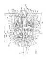
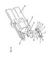
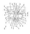
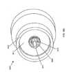
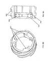
- Figures 1 , 2 , and 3illustrate an embodiment of a continuously variable transmission 100 that is shrouded in a case 40 which protects the transmission 100, contains lubricant, aligns components of the transmission 100, and absorbs forces of the transmission 100.
- a case cap 67can, in certain embodiments, cover the case 40.
- the case cap 67is generally shaped as a disc with a bore, through its center through which an input shaft passes, and that has a set of threads at its outer diameter that thread into a corresponding set of threads on the inner diameter of the case 40.
- the case cap 67can be fastened to the case 40 or held in place by a snap ring and corresponding groove in the case 40, and would therefore not need to be threaded at its outer diameter.
- the case cap 67extends to the inside diameter of the case 40 so that case fasteners (not shown) used to bolt the case 40 to the machinery to which the transmission 100 is attached can be passed through corresponding holes in the case cap 67.
- the case cap 67 of the illustrated embodimenthas a cylindrical portion extending from an area near its outer diameter toward the output side of the transmission 100 for additional support of other components of the transmission 100.
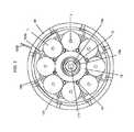
- a plurality of balls 1that are typically spherical in shape and are radially distributed substantially evenly or symmetrically about the centerline, or longitudinal axis 11 of rotation of the transmission 100. In the illustrated embodiment, eight balls 1 are used.
- the transmissionmay include 3, 4, 5, 6, 7, 8, 9, 10, 11, 12, 13, 14, 15 or more balls.
- the provision for more than 3, 4, or 5 ballscan more widely distribute the forces exerted on the individual balls 1 and their points of contact with other components of the transmission 100 and can also reduce the force necessary to prevent the transmission 100 from slipping at the ball 1 contact patches.
- Certain embodiments in applications with low torque but a high transmission ratiouse few balls 1 of relatively larger diameters, while certain embodiments in applications with high torque and a high transmission ratio can use more balls 1 or relatively larger diameters.
- Other embodiments, in applications with high torque and a low transmission ratio and where high efficiency is not importantuse more balls 1 of relatively smaller diameters.
- certain embodiments, in applications with low torque and where high efficiency is not importantuse few balls 1 of relatively smaller diameters.
- Ball axles 3are inserted through holes that run through the center of each of the balls 1 to define an axis of rotation for each of the balls 1.
- the ball axles 3are generally elongated shafts over which the balls I rotate, and have two ends that extend out of either side of the hole through the balls 1. Certain embodiments have cylindrically shaped ball axles 3, although any shape can be used.
- the balls 1are mounted to freely rotate about the ball axles 3.
- bearingsare utilized to reduce the friction between the outer surface of the ball axles 3 and the surface of the bore through the corresponding ball 1.
- These bearingscan be any type of bearings situated anywhere along the contacting surfaces of the balls 1 and their corresponding ball axles 3, and many embodiments will maximize the life and utility of such bearings through standard mechanical principles common in the design of dynamic mechanical systems.
- radial bearingsare located at each end of the bore through the balls 1. These bearings can incorporate the inner surface of the bore or the outer surface of the ball axles 3 as their races, or the bearings can include separate races that fit in appropriate cavities formed in the bore of each ball 1 and on each ball axle 3.
- a cavity (not shown) for a bearingis formed by expanding the bore through each ball 1 at least at both ends an appropriate diameter such that a radial bearing, roller, ball or other type, can be fitted into and held within the cavity thus formed.
- the ball axles 3are coated with a friction reducing material such as babbit, Teflon or other such material.
- Many embodimentsalso minimize the friction between the ball axles 3 and the balls I by introducing lubrication in the bore of the ball axles 3.
- the lubricationcan be injected into the bore around the ball axles 3 by a pressure source, or it can be drawn into the bore by the rifling or helical grooves formed on the ball axles 3 themselves. Further discussion of the lubrication of the ball axles 3 is provided below.
- the axes of rotation of the balls 1are shown tilted in a direction that puts the transmission in a high ratio, wherein the output speed is greater than the input speed. If the ball axles 3 are horizontal, that is parallel to the main axis of the transmission 100, the transmission 100 is in a 1:1 input rotation rate to output rotation rate ratio, wherein the input and output rotation speeds are equal.
- the axes of rotation of the balls 1are shown tilted in a direction where the transmission 100 is in a low ratio, meaning the output rotation speed is slower than the input rotation speed. For the purpose of simplicity, only the parts that change position or orientation when the transmission 100 is shifted are numbered in Figure 2 .
- Figures 1 , 2 , 4 , and 5illustrate how the axes of the balls 1 can be tilted in operation to shift the transmission 100.
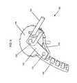
- a plurality of legs 2which in most embodiments are generally struts, are attached to the ball axles 3 near each of the ends of the ball axles 3 that extend beyond the ends of the holes bored through the balls 1.
- Each leg 2extends from its point of attachment to its respective ball axle 3 radially inward toward the axis of the transmission 100.
- each of the legs 2has a through bore that receives a respective end of one of the ball axles 3.
- the ball axles 3preferably extend through the legs 2 such that they have an end exposed beyond each leg 2.
- the ball axles 3advantageously have rollers 4 coaxially and slidingly positioned over the exposed ends of the ball axles 3.
- the rollers 4are generally cylindrical wheels fitted over the ball axles 3 outside of and beyond the legs 2 and rotate freely about the ball axles 3.
- the rollers 4can be attached to the ball axles 3 via spring clips or other such mechanism, or they can ride freely over the ball axles 3.
- the rollers 4can be radial bearings for instance, where the outer races of the bearings form the wheel or rolling surface. As illustrated in Figures 1 and 7 , the rollers 4 and the ends of the ball axles 3 fit inside grooves 86 formed by or in a pair of stators 80a, 80b.
- the stators 80a, 80b of one embodimentare illustrated in Figures 5 and 7 .
- the illustrated input stator 80a and output stator 80bare generally in the form of parallel discs annularly located about the longitudinal axis 11 of the transmission on either side of the balls 1.
- the stators 80a, 80b of many embodimentsare comprised of input stator discs 81a and output stator discs 81b, respectively, which are generally annular discs of substantially uniform thickness with multiple apertures to be discussed further below.
- Each input and output stator disc 81a, 81bhas a first side that faces the balls 1 and a second side that faces away from the balls 1.
- Multiple stator curves 82are attached to the first side of the stator discs 81a, 81b.
- the stator curves 82are curved surfaces attached or affixed to the stator discs 81a, 81b that each have a concave face 90 facing toward the balls 1 and a convex face 91 facing away from the balls 1 and contacting their respective stator discs 81.
- the stator curves 82are integral with the stator discs 81a, 81b.
- the stator curves 82 of many embodimentshave a substantially uniform thickness and have at least one aperture (not separately shown) used to align and attach the stator curves 82 to each other and to the stator discs 81.
- the stator curves 82 of many embodiments, or the stator discs 81 a, 81 b where integral parts are used,include a slot 710 that accepts a flat spacer 83, which allows further positioning and alignment of the stator curves 82 and stator discs 81a, 81b.
- the flat spacers 83are generally flat and generally rectangular pieces of rigid material that extend between and interconnect the input stator 80a and the output stator 80b.
- the flat spacers 83fit within the slots 710 formed in the stator curves 82.
- the flat spacers 83are not fastened or otherwise connected to the stator curves 82, however, in some embodiments the flat spacers 83 are attached to the stator curves 82 by welding, adhesive, or fastening.
- multiple cylindrical spacers 84of a generally cylindrical shape with bores at least in each end, are radially positioned inside of the flat spacers 83 and also connect and position the stator discs 81 and stator curves 82.
- the bores of the cylindrical spacers 84accept one spacer fastener 85 at each end.
- the spacer fasteners 85are designed to clamp and hold the stator discs 81a, 81b, the stator curves 82, the flat spacers 83, and the cylindrical spacers 84 together, which collectively form the cage 89.
- the cage 89maintains the radial and angular positions of the balls 1 and aligns the balls 1 with respect to one another.
- each roller 4fits into and follows a groove 86, which is slightly larger than the diameter of the roller 4, and is formed by the space between each pair of adjacent stator curves 82.
- the rollers 4therefore roll along the surface of the sides 92, 93 of the stator curves 82, a first side 92 and a second side 93 for each stator curve 82, in order to maintain the plane of movement of the ball axles 3 in line with the longitudinal axis 11 of the transmission 100.
- each roller 4rolls on a first side 92 of the stator curve 82 on the input side of the transmission 100 and on the corresponding first side 92 of the corresponding output stator curve 82.
- the forces of the transmission 100prevent the rollers 4 from contacting the second side 93 of the stator curves 82 in normal operation.
- the rollers 4are slightly smaller in diameter than the width of the grooves 86 formed between the stator curves 82, forming a small gap between the edges of the grooves 86 and the circumference of each corresponding roller.
- stator curves 82 on the input stator 80a and output stator 80bwere in perfect alignment, the small gap between the circumferences of the rollers 4 and the grooves 86 would allow the ball axles to slightly tilt and become misaligned with the longitudinal axis 11 of the transmission 100. This condition produces sideslip, a situation where the balls axles 3 are allowed to slightly move laterally, which lowers overall transmission efficiency.
- the stator curves 82 on the input and output sides of the transmission 100may be slightly offset from each other so that the ball axles 3 remain parallel with the axis of the transmission 100.
- the transmission 100is shifted to a lower or higher transmission ratio by changing the rotational axes of the balls 1, each one of the pairs of rollers 4, located on the opposite ends of a single ball axle 3, move in opposite directions along their respective corresponding grooves 86 by rolling up or down a respective side of the groove 86.
- the cage 89can be rigidly attached to the case 40 with one or more case connectors 160.
- the case connectors 160extend generally perpendicularly from the radial outermost part of the flat spacers 83.
- the case connectors 160can be fastened to the flat spacers 83 or can be formed integrally with the flat spacers 83.
- the outside diameter formed roughly by the outsides of the case connectors 160is substantially the same dimension as the inside diameter of the case 40 and holes in both the case 40 and case connectors 160 provide for the use of standard or specialty fasteners, which rigidly attach the case connectors 160 to the case 40, thus bracing and preventing the cage 40 from moving.
- the case 40has mounting holes providing for the attachment of the case 40 to a frame or other structural body.
- the case connectors 160can be formed as part of the case 40 and provide a location for attachment of the flat spacers 83 or other cage 89 component in order to mobilize the cage 89.
- FIGS 1 , 5 , and 7illustrate an embodiment including a pair of stator wheels 30 attached to each of the legs 2 that roll on the concave face 90 of the curved surfaces 82 along a path near the edge of the sides 92, 93.
- the stator wheels 30are attached to the legs 2 generally in the area where the ball axles 3 pass through the legs 2.
- the stator wheels 30can be attached to the legs 2 with stator wheel pins 31, which pass through a bore through the legs 2 that is generally perpendicular to the ball axles 3, or by any other attachment method.
- the stator wheels 30are coaxially and slidingly mounted over the stator wheel pins 31 and secured with standard fasteners, such as snap rings for example.
- the stator wheels 30are radial bearings with the inner race mounted to the stator wheel pins 31 and the outer race forming the rolling surface.
- one stator wheel 30is positioned on each side of a leg 2 with enough clearance from the leg 2 to allow the stator wheels 30 to roll radially along the concave faces 90, with respect to the longitudinal axis 11 of the transmission 100, when the transmission 100 is shifted.
- the concave faces 90are shaped such that they are concentric about a radius from the longitudinal axis 11 of the transmission 100 formed by the center of the balls 1.
- guide wheels 21are illustrated that can be attached to the end of the legs 2 that are nearest the longitudinal axis 11 of the transmission 100.
- the guide wheels 21are inserted into a slot formed in the end of the legs 2.
- the guide wheels 21are held in place in the slots of the legs 21 with guide wheel pins 22, or by any other attachment method.
- the guide wheels 21are coaxially and slidingly mounted over the guide wheel pins 22, which are inserted into bores formed in the legs 2 on each side of the guide wheels 21 and perpendicular to the plane of the slot.
- the legs 2are designed to elastically deflect relatively slightly in order to allow for manufacturing tolerances of the parts of the transmission 100.
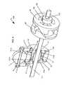
- the ball 1, the legs 2, the ball axle 3, the rollers 4, the stator wheels 30, the stator wheel pins 31, the guide wheels 21, and the guide wheel pins 22collectively form the ball/leg assembly 403 seen in Figure 5 .
- shiftingis actuated by rotating a rod 10 that is positioned outside of the case 40.
- the rod 10is utilized to wrap an unwrap a flexible input cable 155a and a flexible output cable 155b that are attached to, at their respective first ends, and wrapped around the rod 10, in opposite respective directions.
- the input cable 155ais wrapped counter-clockwise around the rod 10 and the output cable 155b is wrapped clockwise around the rod 10, when looking from right to left as the rod 10 is illustrated in Figure 6 .
- Both the input cable 155a and the output cable 155bextend through holes in the case 40 and then through the first end of an input flexible cable housing 151a, and an output flexible cable housing 151b.
- the input flexible cable housing 151a and the output flexible cable housing 151b of the illustrated embodimentare flexible elongated tubes that guide the input cable 155a and output cable 155b radially inward toward the longitudinal axis 11 then longitudinally out through holes in the stator discs 81a, b and then again radially inward where the second end of the input and output flexible cable housings 151a, b are inserted into and attach to the first end of input and output rigid cable housings 153a, b, respectively.
- the input and output rigid cable housings 153a, bare inflexible tubes through which the cables 155a, b, pass and are guided radially inward from the second ends of the flexible cable housings 151 a, b and then direct the cables 155a, b longitudinally through holes in the stator discs 81a, b and toward a second end of the rigid cable housings 153a, b near the idler 18.
- the cables 155a, bare attached at their second ends to an input shift guide 13a, and an output shift guide 13b (described further below) with conventional cable fasteners, or other suitable attachment means.
- the shift guides 13a, 13bposition the idler 18 axially along the longitudinal axis 11 and position the legs 3 radially, thereby changing the axes of the balls 1 and the ratio of the transmission 100.
- the input cable 155aunwinds from the rod 10 and the output cable 155b winds onto the rod 10. Therefore, the second end of the output cable 155b applies a tension force to the output shift guide 13b and the input cable 155a is unwinding a commensurate amount from the rod 10. This moves the idler 18 axially toward the output side of the transmission 100 and shifts the transmission 100 toward low.
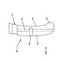
- the illustrated shift guides 13a, bare each generally of the form of an annular ring with inside and outside diameters, and are shaped so as to have two sides.
- the first sideis a generally straight surface that dynamically contacts and axially supports the idler 18 via two sets of idler bearings 17a, 17b, which are each associated with a respective shift guide 13a, b.
- the second side of each shift guide 13a, b, the side facing away from the idler 18,is a cam side that transitions from a straight or flat radial surface 14, towards the inner diameter of the shift guides 13a, b, to a convex curve 97 towards the outer diameter of the shift guides 13a, b.
- a longitudinal tubular sleeve 417a, bextends axially toward the opposing shift guide 13a, b in order to mate with the tubular sleeve 417a, b from that shift guide 13a, b.
- the tubular sleeve of the input side shift guide 13ahas part of its inner diameter bored out to accept the tubular sleeve of the output shift guide 13b.
- the cross section side view of the shift guides 13a, b illustrated in Figure 4shows that, in this embodiment, the flat surface 14 profile of the side facing away from the is perpendicular to the longitudinal axis 11 up to a radial point where the guide wheels 21 contact the shift guides 13 a, b, if the ball axles 3 are parallel with the longitudinal axis 11 of the transmission 100. From this point moving out toward the perimeter of the shift guide 13a, b the profile of the shift guides 13a, b curves in a convex shape.
- the convex curve 97 of a shift guide 13a, bis not a radius but is composed of multiple radii, or is shaped hyperbolically, asymptotically or otherwise.
- the shift guides 13a, bcan be attached to each other by either threading the tubular sleeve of the input shift guide 13a with male threads and the tubular sleeve of the output sleeve 13b with female threads, or vice versa, and threading the shift guides 13a, b, together.
- One shift guide 13a, b, either the input or output,can also be pressed into the other shift guide 13a, b.
- the shift guides 13 a, bcan also be attached by other methods such as glue, metal adhesive, welding or any other means.
- the convex curves 97 of the two shift guides 13a, bact as cam surfaces, each contacting and pushing the multiple guide wheels 21.
- the flat surface 14 and convex curve 97 of each shift guide 13a, bcontact the guide wheels 21 so that as the shift guides 13 a, b, move axially along the longitudinal axis 11, the guide wheels 21 ride along the shift guide 13a, b surface 14, 97 in a generally radial direction forcing the leg 2 radially out from, or in toward, the longitudinal axis 11, thereby changing the angle of the ball axle 3 and the rotational axis of the associated ball 1.
- the idler 18 of some embodimentsis located in a trough formed between the first sides and the sleeve portions of the shift guides 13 a, b, and thus moves in unison with the shift guides 13a, b.
- the idler 18is generally tubular and of one outside diameter and is substantially cylindrical along the central portion of its inside diameter with an input and output idler bearing 17a, b, on each end of its inside diameter.
- the outer diameter and inside diameters of the idler 18can be non-uniform and can vary or be any shape, such as ramped or curved.
- the idler 18has two sides, one near the input stator 80a, and one near the output stator 80b.
- the idler bearings 17a, 17bprovide rolling contact between the idler 18 and the shift guides 13a, b.
- the idler bearings 17a, 17bare located coaxially around the sleeve portion of the shift guides 13a, b, allowing the idler 18 to freely rotate about the axis of the transmission 100.
- a sleeve 19is fit around the longitudinal axis 11 of the transmission 100 and fitting inside the inside diameters of the shift guides 13a, b.
- the sleeve 19is a generally tubular component that is held in operable contact with an inside bearing race surface of each of the shift guides 13a, b by an input sleeve bearing 172a and an output sleeve bearing 172b.
- the sleeve bearings 172a, bprovide for rotation of the sleeve 19 by rolling along an outer bearing race complimentary to the races of the shift guides 13a, b.
- the idler 18, the idler bearings 17a, 17b, the sleeve 19, the shift guides 13a, 13b, and the sleeve bearings 172a, 172bcollectively form the idler assembly 402, seen in Figure 4 .
- the sleeve 19 of some embodimentshas its inside diameter threaded to accept the threaded insertion of an idler rod 171.
- the idler rod 171is a generally cylindrical rod that lies along the longitudinal axis 11 of the transmission 100. In some embodiments, the idler rod 171 is threaded at least partially along its length to allow insertion into the sleeve 19.
- the first end of the idler rod 171, which faces the output side of the transmission 100,is preferably threaded through the sleeve 19 and extends out past the output side of the sleeve 19 where it is inserted into the inside diameter of the output disc 101.
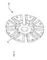
- the output disc 101in some embodiments is generally a conical disc that is spoked to reduce weight and has a tubular sleeve portion extending from its inner diameter axially toward the output side of the transmission 100.
- the output disc 101transfers the output torque to a drive shaft, wheel, or other mechanical device.
- the output disc 101contacts the balls 1 on their output side and rotates at a speed different than the input rotation of the transmission at ratios other than 1:1.
- the output disc 101serves to guide and center the idler rod 171 at its first end so that the sleeve 19, idler 18, and shift guides 13a, b stay concentric with the axis of the transmission 100.
- annular bearingmay be positioned over the idler rod 171, between the idler rod 171 and the inside diameter of the output disc 101, to minimize friction.
- the idler rod 171, sleeve 19, shift guides 13a, b, and idler 18are operably connected, and all move axially in unison when the transmission 100 is shifted.
- a conical spring 133positioned between the input shift guide 13a and stator 80a biases the shifting of the transmission 100 toward low.
- output disc bearings 102which contact a bearing race near the perimeter of the output disc 101, absorb and transfer axial force generated by the transmission 100 to the case 40.
- the case 40has a corresponding bearing race to guide the output disc bearings 102.
- the limits of the axial movement of the shift guides 13a, bdefine the shifting range of the transmission 100.
- Axial movementis limited by inside faces 88a, b, on the stator discs 81a, b, which the shift guides 13a, b, contact.
- shift guide 13acontacts the inside face 88a on the input stator discs 81a
- the shift guide 13bcontacts the inside face 88 on the output stator disc 81b.
- the curvature of the convex curves 97 of the shift guides 13a, bis functionally dependent on the distance from the center of a ball 1 to the center of the guide wheel 21, the radius of the guide wheel 21, the angle between lines formed between the two guide wheels 21 and the center of the ball 1, and the angle of tilt of the ball 1 axis.
- An example of such a relationshipis described below, with respect to Figures 25, 26 and 27 .
- one or more stator wheels 30can be attached to each leg 2 with a stator wheel pin 31 that is inserted through a hole in each leg 2.
- the stator wheel pins 31are of the proper size and design to allow the stator wheels 30 to rotate freely over each stator wheel pin 31.
- the stator wheels 30roll along the concave curved surfaces 90 of the stator curves 82 that face the balls 1.
- the stator wheels 30provide axial support to prevent the legs 2 from moving axially and also to ensure that the ball axles 3 tilt easily when the transmission 100 is shifted.
- a spoked input disc 34located adjacent to the stator 80a, partially encapsulates but generally does not contact the stator 80a.
- the input disc 34may have two or more spokes or may be a solid disc. The spokes reduce weight and aid in assembly of the transmission 100. In other embodiments a solid disc can be used.
- the input disc 34has two sides, a first side that contacts with the balls 1, and a second side that faces opposite the first side.
- the input disc 34is generally an annular disk that fits coaxially over, and extends radially from, a set of female threads or nut 37 at its inner diameter.
- the outside diameter of the input disc 34is designed to fit within the case 40, if the case 40 used is the type that encapsulates the balls 1 and the input disc 34 and mounts to a rigid support structure 116 such as a chassis or frame with conventional bolts, which are inserted through bolt holes in a flange on the case 40.
- the input disc 34is in rotating contact with the balls 1 along a circumferential ramped or bearing contact surface on a lip of the first side of the input disc 34, the side facing the balls 1.
- some embodiments of the input disc 34have a set of female threads 37, or a nut 37, inserted into its inside diameter, and the nut 37 is threaded over a screw 35, thereby engaging the input disc 34 with the screw 35.
- the screw 35is attached to and rotated by a drive shaft 69.
- the drive shaft 69is generally cylindrical and has an inner bore, a first end facing axially towards the output side, a second end facing axially toward the input side, and a generally constant diameter.
- the drive shaft 69is rigidly attached to and rotated by the input torque device, usually a gear, a sprocket, or a crankshaft from a motor.
- the drive shaft 69has axial splines 109 extending from its second end to engage and rotate a corresponding set of splines formed on the inside diameter of the screw 35.
- a set of central drive shaft ramps 99which on a first side is generally a set of raised inclined surfaces on an annular disk that is positioned coaxially over the drive shaft 69, have mating prongs that mate with the splines 109 on the drive shaft 99, are rotated by the drive shaft 69, and are capable of moving axially along the drive shaft 69.
- a pin ring 195contacts a second side of the central drive shaft ramps 99.
- the pin ring 195is a rigid ring that is coaxially positioned over the idler rod 171, is capable of axial movement and has a transverse bore that functions to hold an idler pin 196 in alignment with the idler rod 171.
- the idler pin 196is an elongated rigid rod that is slightly longer than the diameter of the pin ring 195 and which is inserted through an elongated slot 173 in the idler rod 171 and extends slightly beyond the pin ring 195 at both its first and second ends when it is inserted into the bore of the pin ring 195.
- the elongated slot 173 in the idler rod 171allows for axial movement of the idler rod 171 to the right, when viewed as illustrated in Figure 1 , without contacting the pin 196 when the transmission 100 is shifted from 1:1 toward high.
- the idler rod 171is thus operably connected to the central drive shaft ramps 99 when the transmission is between 1:1 and low so that when the idler rod 171 moves axially the central drive shaft ramps 99 also move axially in conjunction with the idler rod 171.
- the ramp surfaces of the central drive shaft ramps 99can be helical, curved, linear, or any other shape, and are in operable contact with a set of corresponding central bearing disc ramps 98.
- the central bearing disc ramps 98have ramp faces that are complimentary to and oppose the central drive shaft ramps 99. On a first side, facing the output side of the transmission 100, the central bearing disc ramps 98 face the central drive shaft ramps 99 and are contacted and driven by the central drive shaft ramps 99.
- the central bearing disc ramps 98are rigidly attached to a bearing disc 60, a generally annular disc positioned to rotate coaxially about the longitudinal axis 11 of the transmission 100.
- the bearing disc 60has a bearing race near its perimeter on its side that faces away from the balls 1 that contacts a bearing disc bearing 66.
- the bearing disc bearing 66is an annular thrust bearing at the perimeter of the bearing disc 60 and is positioned between the bearing disc 60 and the input disc 34.
- the bearing disc bearing 66provides axial and radial support for the bearing disc 60 and in turn is supported by a bearing race on a case cap 67, which acts with the case 40 to partially encapsulate the inner parts of the transmission 100.
- the case cap 67is generally an annular disc extending from the drive shaft 69 having a tubular portion extending toward the output end from at or near its perimeter and also having a bore through its center.
- the case cap 67absorbs axial and radial forces produced by the transmission 100, and seals the transmission 100, thereby preventing lubricant from escaping and contamination from entering.
- the case cap 67is stationary and, in some embodiments, is rigidly attached to the case 40 with conventional fastening methods or can have male threads on its outside diameter, which mate with corresponding female threads on the inside diameter of the case 40.
- the case cap 67has a bearing race that contacts the bearing disc bearing 66 near the perimeter of the bearing disc 60 that is located at the inside of the output end of the tubular extension from the case cap 67.
- the case cap 67also has a second bearing race facing the output side located near the inside diameter of its annular portion that mates with a drive shaft bearing 104.
- the drive shaft bearing 104is a combination thrust and radial bearing that provides axial and radial support to the drive shaft 69.
- the drive shaft 67has a bearing race formed on its outside diameter facing the input side that mates with the drive shaft bearing 104, which transfers the axial force produced by the screw 35 to the case cap 67.
- An input bearing 105adds support to the drive shaft 69.
- the input bearing 105is coaxially positioned over the drive shaft 69 and mates with a third race on the inside diameter of the case cap 67 facing the input side of the transmission 100.
- a cone nut 106a generally cylindrical threaded nut with a bearing race designed to provide a running surface for the input bearing 105, is threaded over the drive shaft 69 and supports the input bearing 105.
- a set of multiple perimeter ramps 61are rigidly attached to the bearing disc 60.
- the perimeter ramps 61are multiple inclined surfaces that are positioned radially about the longitudinal axis 11 and are positioned against or formed on the bearing disc 60 and face the output side.
- the inclined surfacescan be curved, helical, linear, or another shape and each one creates a wedge that produces and axial force that is applied to one of multiple ramp bearings 62.
- the ramp bearings 62are spherical but can be cylindrical, conical, or another geometric shape, and are housed in a bearing cage 63.
- the bearing cage 63 of the illustrated embodimentis generally ring shaped with multiple apertures that contain the individual ramp bearings 62.
- a set of input disc ramps 64are rigidly attached to, or formed as part of, the input disc 34.
- the input disc ramps 64in some embodiments are complimentary to the perimeter ramps 62 with the ramps facing toward the input side.
- the input disc ramps 64are in the form of a bearing race that aligns and centers the ramp bearings 62 radially.
- the ramp bearings 62respond to variations in torque by rolling up or down the inclined faces of the perimeter ramps 61 and the input disc ramps 64.
- an axial force generator 160is made up of various components that create an axial force that is generated and is applied to the input disc 34 to increase the normal contact force between the input disc 34 and the balls 1, which is a component in the friction the input disc 34 utilizes in rotating the balls 1.
- the transmission 100produces sufficient axial force so that the input disc 34, the balls 1, and the output disc 101 do not slip, or slip only an acceptable amount, at their contact points.
- an appropriate amount of additional axial forceis required to prevent slippage.
- more axial forceis required to prevent slippage in low than in high or at a 1:1 speed ratio.
- the axial force generator 160will vary the axial force applied to the balls 1 as the transmission 100 is shifted and also as torque is varied. In some embodiments, the transmission 100 accomplishes both these goals.
- the screw 35is designed and configured to provide an axial force that is separate and distinct from that produced by the perimeter ramps 61. In some embodiments the screw 35 produces less axial force than the perimeter ramps 61, although in other versions of the transmission 100, the screw 35 is configured to produce more force than the perimeter ramps 61.
- the screw 35Upon an increase in torque, the screw 35 rotates slightly farther into the nut 37 to increase axial force by an amount proportional to the increase in torque.
- the idler rod 171moves axially toward the input side, along with the sleeve 19, sleeve bearings 172, shift guides 13a, b, and idler 18.
- the idler rod 171contacts the central drive shaft ramps 99 through the pin 196 and pin ring 195, causing the central drive shaft ramps 99 to move axially toward the output side.
- the ramped surfaces of the central drive shaft ramps 99contact the opposing ramped surfaces of the central bearing disc ramps 98, causing the central bearing disc ramps 98 to rotate the bearing disc 67 and engage the perimeter ramps 61 with the ramp bearings 62 and the input disc ramps 64.
- the central drive shaft ramps 99 and the central bearing disc ramps 98perform a torque splitting function, shifting some of the torque from the screw 35 to the perimeter ramps 61. This increases the percentage of transmitted torque that is directed through the perimeter ramps 61, and due to the fact the perimeter ramps 61 are torque sensitive as described above, the amount of axial force that is generated increases.
- the legs 2 attached to the ball axles 3transfer the pull to the shift guides 13a, b, and because the shift guides 13a, b, are operably attached to the idler 18 and sleeve 19, an axial force is transferred to the idler rod 171.
- the influence of contact spinincreases at all ratios and efficiency decreases.
- the disengagement mechanismis located between the input disc 35 and the bearing disc 60 and disengages the transmission 100 when output rotation is greater than input rotation.
- the disengagement mechanismis comprised of multiple parts, including an input disc connector 121, a generally cylindrical elongated pin that is rigidly attached to the input disc 34 near its perimeter, which protrudes from the input disc 35 towards the bearing disc 60 in a direction substantially parallel to the longitudinal axis 11 of the transmission 100.
- the input disc connector 121engages a clutch lever 122 at a first end.
- the clutch lever 122is a generally L - shaped flat piece of rigid material, having its first end extending as its short leg and a second end extending as its long leg, and that pivots on a preloader 123 from a joint at the intersection of its legs.
- the engagement of the input disc connector 121 and the first end of the clutch lever 122is sliding engagement and allows relative movement between the input disc connector 121 and the clutch lever 122.
- the clutch lever 122 jointis formed by a through hole that is positioned over the preloader 123.
- the preloader 123is a flexible, elongated rod that can also be square, flat, or of any other cross-sectional shape and is attached at one of its ends to a hole extending radially through the bearing cage 63, and at a second end is rigidly attached to the drive shaft 69.
- the preloader 123can bias the ramp bearings 62 up the perimeter ramps 61, it can pull the input disc 34 off of the balls during times when the disengagement mechanism is activated, and it can serve as a means of attachment for other components, such as disengagement mechanism 120 components.
- a pawl 124is also attached to the clutch lever 122.
- the pawl 124is generally wedge-shaped and at a first end tapers to a point, and at a second end is rounded with a through hole.
- a pawl pin 125is inserted into a hole in the second end of the clutch lever 122, thereby attaching the pawl 124 to the clutch lever 122 while allowing for rotation of the pawl 124 about the pawl pin 125.
- the pawl 124mates with and contacts a disc shaped ratchet 126, which has teeth around its circumference and lays flat against the back of the clutch lever 122.
- ratchet 126At the center of the ratchet 126 is a hole through which the preloader 123 passes adjacent to the clutch lever 122 and radially inward toward the longitudinal axis 11 of the transmission 100.
- the ratchet 126is held in place by conventional fasteners and is capable of rotation about the preloader 123.
- a ratchet bevel 127a gear with beveled teeth around its perimeter, is rigidly and coaxially attached to and made a part of the ratchet 126.
- the teeth on the ratchet bevel 127mesh with a bevel gear 128.
- the bevel gear 128is a ring that is rigidly attached to the bearing disc 60 in the illustrated embodiment, but which can be attached to other rotating components such as the drive shaft 69 and central drive shaft ramps 99.
- the bevel gear 128has teeth around its perimeter that mate with the teeth on the ratchet 126.
- a main spring 129a coiled spring with multiple coils as illustrated in Figure 11 , is coaxially positioned around the longitudinal axis 11 of the transmission 100 and is attached at a first end to the input disc 34 and at a second end to the bearing disc 60.
- the main spring 129biases the input disc 34 to rotate about or "unwind" from the screw 35 so that the input disc 34 contacts the balls 1.
- the pawl 124locks onto the teeth of the ratchet 126, preventing the input disc 34 from unwinding off of the screw 35 in a second direction and again contacting the balls 1, as the bias of the main spring 129 would tend to do.
- the ratchet 126is prevented from rotating in a second direction because the ratchet bevel 127, a part of the ratchet 126, has teeth that are interlocked with the bevel gear 128 which is not rotating.
- the bevel gear 127is rotated by the bearing disc 60 in a first direction, which rotates the ratchet bevel 127 and ratchet 126 in a second direction, thus rotating the pawl 124 in a second direction, allowing the main spring 129 to bias the input disc 34 to unwind from the screw 35 in a second direction and contact the balls 1.
- the bearing cage 63attached to the preloader 123 at a first end, causes the preloader 123 to rotate relative to the input disc 34 when the input disc 34 rotates in a first direction. This is due to the ramp bearings 62 rotating relative to the input disc 34 when the input disc 34 is rotating in a first direction.
- the bearing disc 60rotates relative to the preloader 123 due to the same relative rotation. This action provides for the engagement and release of the disengagement mechanism 120.
- a latch 115rigidly attaches to the side of the input disc 34 that faces the bearing disk 60 and engages a hook 114 that is rigidly attached to a first of two ends of a hook lever 113.
- the hook lever 113is an elongated strut with the hook 114 at its first end and a hook hinge 116 at its second end.
- the latch 115has an engaging area or an opening that is larger than the width of the hook 114 and provides extra room for the hook 114 to move radially, with respect to the longitudinal axis 11, within the confines of the latch 114 when the input disc 34 and the bearing disk 60 move relative to each other.
- the hood hinge 116engages a middle hinge 119 and forms a hinge joint with a first hinge pin 111.
- the middle hinge 119is integral with a first end of an input disc lever 112, which is a generally elongated strut having two ends.
- the input disc lever 112On its second end, the input disc lever 112 has an input disc hinge 117, which engages a hinge brace 110 via the use of a second hinge pin 118.
- the hinge brace 110is generally a base to support the hook 114, the hook lever 113, the hook hinge 116, the first hinge pin 111, the middle hinge 119, the input disc lever 112, the second hinge pin 118, and the input disc hinge 117, and it is rigidly attached to the bearing disc 60 on the side facing the input disc 34.
- a preloader 123is attached at a first end to the drive shaft 69 and extends radially outward. At a second end the preloader contacts the input disc lever 112, biasing the input disc 34 away from the balls 1, so that on occasions when the input disc 34 disengages from the balls 1, it is biased to remain disconnected.
- the illustrated axial force generatorincludes one or more reversing levers 261.
- the reversing levers 261are generally flat, irregularly shaped cam pieces each having an off-center mounted pivot hole with a first side radially inward of the pivot hole and a second side radially outside of the pivot hole. The first side of the reversing levers 261 each fit into the elongated slot 173 in the idler rod 171.
- the reversing levers 261can be designed to decrease the distance that they move axially toward the input side and increase the force they produce.
- the reversing levers 261can be designed in this manner to create a mechanical advantage to adjust the axial force that they produce.
- the reversing levers 261At their second sides, the reversing levers 261 each contact the output side of the central screw ramps 298 when the transmission 100 is shifted toward low.
- the reversing levers 261are each attached to a lever ring 263 by the reversing pins 262, which can be pressed or threaded into holes in the lever ring 263 to hold the reversing levers 261 in position.
- the lever ring 263is a ring shaped device that fits around, and slides axially along, the idler rod 171 and has one or more rectangular slots cut through it to allow for insertion and positioning of the reversing levers 261.
- a set of central screw ramps 299is rigidly attached to and can be rotated by the screw 35.
- the central screw ramps 299 of this embodimentare similar to the central screw ramps 99 illustrated in Figure 4 , in that the central screw ramps 299 are formed as ramps on the second side of a disc having a first side facing the output side and a second side facing the input side. As the transmission 100 is shifted toward low, the second side of the reversing levers 261 pushes against the first side of the central screw ramps 299.
- the central screw ramps 299which are splined to the drive shaft 69 via the above-described spline 109, are rotated by the drive shaft 69, are capable of axial movement along the longitudinal axis 11, and are similar to the central drive shaft ramps 99 of the previous embodiment, except that the central screw ramps 299 face the input side of the transmission 100 rather than the output side.
- the central screw ramps 299contact an opposing set of central bearing disc ramps 298, which are free to rotate relative to the drive shaft 69 and are similar to the central bearing disc ramps 98 illustrated in Figure 4 , except that the central bearing disc ramps 298 face the output side of the transmission 100 rather than the input side.
- FIG. 11a cutaway side view of an alternative embodiment of the transmission 100 of Figure 1 is disclosed.
- the transmission 300has an alternative cage 389, an alternative disengagement mechanism (item 320 of Figures 13 and 14 ) , and an alternative axial force generator.
- the conical spring 133is moved to the output side of the transmission 300, biasing the shifting toward high.
- the cage 389includes input and output stator discs 381a, b, however for ease of viewing, the output stator disc 381b has been removed.
- the output stator 381b of many embodimentsis structurally similar to the input stator 381a.
- Multiple stator curves 382are attached to the stator discs 381a, b and have first sides facing the balls 1 and second sides facing away from the balls 1.
- the second side 391 of each of the stator curves 382is a flat surface that lays flat against a respective one of the stator discs 181a, b.
- the stator curves 382have two through holes that are used to attach the stator curves 382 to the stator discs 381a, b with conventional fasteners or other type of attachment mechanism.
- the stator curves 382have on each of their first sides a rectangular slot into which multiple flat spacers 383 are inserted to connect the stators 381.
- the flat spacers 383serve to set the distance between the stators 381, create a strong connection between the stators 381, and ensure that the stators 381 1 are parallel and in alignment.
- the illustrated designincorporates a stator disc 181 that is substantially flat. Therefore, the stator discs 181 can be manufactured utilizing a substantially flat sheet of rigid material.
- the stator discs 181can be produced from any of a number of inexpensive manufacturing techniques such as stamping, fine blanking, or any other such technique known in the industry.
- the stator discs 181 of this designcan be made from thin or sheet metal, plastic, ceramic, wood or paper products or any other material.
- the illustrated designallows for significant reduction in the cost of materials and manufacturing of these otherwise relatively expensive components to a suitably high tolerance.
- Figure 13is a cutaway schematic view looking from near the axis of the transmission 300
- Figure 14is a cutaway schematic view looking from above and outside the transmission 300 generally radially inward toward the center.
- the ratchet 126 and the ratchet bevel 127 of the previously described embodimentare merged in the present embodiment into one pawl gear 326 that engages the pawl 124 and has teeth that interlock with the bevel gear 328.
- the bevel gear 328in other embodiments may have non-beveled gear teeth.
- the clutch lever 322is a rigid, flat L-shaped component having three or more holes.
- the centermost hole at the joint of the two legs forming the "L" shapepositions the clutch lever 322 rotatably and coaxially about the preloader 123.
- a hole near the end of the long leg of the clutch lever 322allows for insertion of the pawl pin 125 and attachment to the pawl 124.
- the input disc connector 321is rigidly attached to the input disc 34 and has a slot providing for sliding engagement of the clutch pin 329.
- the operation of the alternative disengagement mechanism 320is otherwise the same as the coasting mechanism 120 previously described and illustrated in Figures 1 and 9 .
- an alternative axial force generatorincludes a generally conical wedge 360 that is positioned and is capable of axial movement along the central axis of the transmission 300.
- the conical wedge 360is also mated with the spline 109.
- AFGaxial force generator
- the AFG lever 362is a generally elongated part having a first semi-circular end that engages the conical wedge 360 and then extends radially outward from the longitudinal axis 11 to a second end that engages the input disc lever 112.
- the AFG lever 362is attached to the spline 109 with a fulcrum pin 361 about which the AFG lever 362 rotates.
- the fulcrum pin 361provides for pivoting of the AFG lever 362 so that the second end of the AFG lever 362 engages the input disc lever 112.
- the input disc lever 112is operably attached to the bearing disc 60 and rotates the bearing disc 60 so that the perimeter ramps 61 engage, thus shifting input torque from the screw 35 to the perimeter ramps 61.
- the operation of the alternative axial force generator 360is otherwise the same as the axial force generator previously described and seen in Figures 1 and 4 .
- the transmission 100 of Figure 1includes one variator,
- the term variatorcan be used to describe the components of the transmission 100 that vary the input to output speed ratio.
- the assemblies and components comprising the variator 401 of the present embodimentinclude the ball/leg assembly 403 of Figure 5 , the input disc 34, the output disc 101, the idler assembly 402 of Figure 4 , and the cage 89 of Figure 7 . It should be noted that all components and assemblies of the variator 401 can change to best fit the specific application of the transmission 1700, and in Figure 16 generic forms of the assemblies and components comprising the variator 401 are depicted.
- the embodiment of the transmission 1700 illustrated in Figure 17is similar to the transmission 100 of but includes two variators 401.
- This configurationis beneficial for applications where high torque capacity is required in a transmission 1700 with a small diameter or overall size.
- This configurationalso eliminates radial bearings needed to support the bearing disc 114 and the output disc 101, thereby increasing overall efficiency.
- the convention or marking like components with an "a" and a "b" to differentiate between the input and output sidesis not used.
- the input sideis to the right and the input is to the left.
- a case 423that surrounds and encapsulates the transmission 1700.
- the case 423is generally cylindrical and protects the transmission 1700 from outside elements and contamination and additionally contains lubrication for proper operation.
- the case 423is attached to an engine, frame, or other rigid body (not shown) with standard fasteners (not shown), which fit through case holes 424.
- the case 423is open on the input side, the side with the case holes 424 or to the right as illustrated, to accept an input torque.
- Input torqueis transmitted from an outside source to an input shaft 425, which is a long, rigid, rod or shaft capable of transmitting torque.
- the input shaft 425transmits torque to a bearing disc 428 via splines, keying, or other such manner.
- the bearing disc 428is a disc-shaped rigid component capable of absorbing significant axial forces produced by the transmission 1700 and is similar in design to the bearing disc 60 illustrated in Figure 1 .
- An input shaft bearing 426is positioned coaxially over the input shaft 425 between a flange 429 on the input end of the input shaft 425 and the bearing disc 428 to allow a small amount of relative movement between the bearing disc 428 and the input shaft 425.
- the bearing disc 429begins rotating, the perimeter ramps 61, ramp bearings 62, bearing cage 63, input disc ramps 64, and input disc 34 rotate as previously described. This rotates the balls 1 in the first variator 420, is the one on the input side.
- a second input disc 431is rotated.
- the second input disc 431is rigidly attached to the input shaft 425, and can be keyed with a backing nut, pressed over the input shaft 425, welded, pinned, or attached by other methods.
- the second input disc 431is located on the output side of the transmission 1700, opposite the bearing disc 428.
- the second input disc 431 and the bearing disc 428absorb the considerable axial forces created by the perimeter ramps 61, ramp bearings 62, and input disc ramps 64 that act as normal forces to prevent slippage at the ball/disc contact patches as previously described.
- the second input disc 431 1is similar in shape to the input disc 34 previously described and upon rotation of the input shaft 425; it rotates the balls I in the second variator 422.
- the second variator 422is generally a mirror image of the first variator 420 and is positioned farther from the input side of the transmission 1700 so that the first variator 420 is situated between it and the input side.
- the balls 1 in the first variator 420rotate the output disc 430 through their rolling contact with that component.
- the output disc 430although serving the same function as the output disc 101 previously described, has two opposing contact surfaces and contacts balls 1 on both variators 420, 422. From the cross sectional view illustrated in Figure 17 , the output disc 430 can be shaped in a shallow arch or upside down shallow "V," the ends of which have a contact surface to contact the balls 1 of the two variators 420, 422.
- the output disc 430surrounds the second variator 422 and extends toward the output side in a generally cylindrical shape.
- the cylindrical shape of the output disc 430continues toward the output side of the transmission 1700 surrounding the second input disc 431 after which the diameter of the output disc 430 decreases and then again becomes a generally cylindrical shape of a smaller diameter as it exits the case 423.
- annular bearings 434, 435may be used to radially align the output disc 431.
- a case bearing 434is positioned in the bore of the case 423 and over the output disc 430 and an output disc bearing 435 is positioned in the bore of the output disc 430 and over the input shaft 425 to provide additional support.
- the output disc 430can be made of two pieces that are connected together to form the illustrated output disc 430. This allows for assembly of the second variator 422 inside the cylindrical shell of the output disc 430.
- the ball axles 433 of the transmission 1700are similar to the ball axles 3 previously described and perform the same function.
- the ball axles 433serve as the mechanism by which the balls 1 are tilted to vary the speed ratio of the transmission 1700.
- the ball axles 433are elongated on each of their respective output sides and extend through the walls of the output stators 435.
- the output stators 435are similar to the output stators 80b previously described, but the multiple radial grooves 436 penetrate all the way through the walls of the output stators 435.
- the grooves 436 of the output stators 435continue all the way through the output stator 435 walls so that a series of equally spaced radial grooves 436 extend radially from near the bore at the center of the output stator 435 to the perimeter.
- the ball axles 433have iris rollers 407 positioned coaxially over their elongated output ends.
- the iris rollers 407are generally cylindrical wheels that are capable of rotating over the ball axles 433 and are designed to fit inside the grooves 411 of an iris plate 409.
- the iris plate 409is an annular disc or plate with a bore through its center that fits coaxially about the longitudinal axis 11 of the transmission 1700.
- the iris plate 409is of a thickness that is greater than twice the thickness of each iris roller 407 and has a number of iris grooves 411 extending radially outward from near the bore to near the perimeter of the iris plate 409.
- the iris grooves 411extend radially, their angular position changes as well, so that as the iris plate 409 is rotated angularly about the longitudinal axis 11, the iris grooves 411 provide a camming function along their respective lengths. In other words, the grooves 411 spiral out from near the bore in the center of the iris plate 409 to respective points near its perimeter.
- the iris rollers 407are radiused along their outside diameters, or have fillets on their outer corners, so that their diameters remain unchanged inside the grooves 411 of the iris plate 409 when the ball axles 433 are tilted.
- the iris plate 409is of a thickness sufficient to allow iris rollers 407 from both variators 420, 422, to remain inside the grooves 411 of the iris plate 433 at all shifting ratios.
- the iris grooves 411operate in traditional iris plate fashion and cause the ball axles 433 to move radially inward or outward when the iris plate 409 is rotated.
- the iris plate 409has a first side facing the first variator and a second side facing the second variator and is coaxially positioned about the longitudinal axis 11 of the transmission 1700 and over abutting bosses on, tubular extensions extending from, the two output stators 435.
- the two output stators 435can be attached to each other with conventional fasteners through axial holes (not illustrated) in the bosses of the output stators 435.
- the output stator 435 bosseshave a hole through their centers and multiple holes positioned radially outward from the center.
- the bosses on the output stators 435form a space slightly wider than the iris plate 409 to provide freedom of rotation for the iris plate 433 and some embodiments utilize bearings between the bosses and the iris plate 409 to accurately control the position of the iris plate 409 between the output stators 435.
- An iris cable 406is attached to the first side of the iris plate 409 near the outside diameter of the iris plate 409 and extends longitudinally from the point of connection. The iris cable 406 is routed through the output stator 435 of the first variator 420 in an orientation so that when it is pulled, it rotates the iris plate 409.
- the iris cable 406, after passing through an aperture near the perimeter of the output stator 435is routed through the case 423 to the outside of the transmission 1700 where it allows for control of the transmission ratio.
- An iris spring 408is attached to the second side of the iris plate 409 near its outside diameter.
- the iris spring 408is also attached to the output stator 435 of the second variator 422.
- the iris spring 408applies a resilient force that resists rotation of the iris plate 409 from tension applied by the iris cable 406. When tension from the iris cable 406 is released, the iris spring 408 returns the iris plate 409 to its at rest position.
- the iris plate 409can be configured so that when the iris cable 406 is pulled the iris plate 409 shifts the transmission 1700 to a higher transmission ratio, and when tension on the iris cable 406 is released the iris spring 408 shifts the transmission 1700 to a low ratio.
- the iris plate 409can be configured so that when the iris cable 406 is pulled the iris plate 409 shifts the transmission 1700 to a lower ratio, and when tension on the iris cable 406 is released the iris spring 408 shifts the transmission 1700 to a high ratio.
- embodiments of the transmission 1700 having two variators 420, 422require a high degree of accuracy in the alignment of the additional rolling elements of the transmission 1700. All of the rolling elements must be aligned with one another or efficiency will suffer and the lifespan of the transmission 1700 will be reduced.
- the input disc 34, the output disc 430, the second input disc 431, and the idler assemblies 402are aligned on the same longitudinal axis.
- the cage 410which in these embodiments consist of two cages 89 joined by the output stators 435 as previously described, must also be aligned on the longitudinal axis to accurately position the ball/leg assemblies 403. To accomplish this simply and accurately, all rolling elements are positioned relative to the input shaft 425.
- a first input stator bearing 440 and a second input stator bearing 444are positioned in the bores of the input stators 440, 444 and over the input shaft 425 to help align the cage 410.
- An output stator bearing 442 positioned in the bore of the output stators 435 and over the input shaft 425also aligns the cage 410.
- a first guide bearing 441is positioned in the bore of the first shift guide 13b and over the input shaft 425 and a second guide bearing 443 is positioned in the bore of the second shift guide 13b and over the input shaft 425 to align the first and second idler assemblies 402.
- the cage 410is attached to the case 423 with the previously described case connectors 383 that fit into case slots 421.
- the case slots 421are longitudinal grooves in the case 423 that extend to the input side of the case 423, the side of the case 423 that is open.
- the caseis mostly closed on the output side, which is not shown in Figure 19 , but is open on the input side and has a mounting flange extending radially from the other wise cylindrical body of the case 423 that case holes 424 for mounting the case 423.
- the transmission 1700can be inserted into the case 423 where the case connecters 383 are aligned in the case slots 421 in order to resist torque applied to the cage 410 and prevent the cage 410 from rotating.
- Case connector holes 412 in the case 423allow fasteners to be inserted into corresponding holes in the case connectors 383 to fasten the cage 410 to the case 423.
- FIG 22illustrates an alternate embodiment of the cage 470 of the transmission 1700.
- the illustrated cage 470uses four different parts of low cost design and common fasteners to assemble the various components.
- the stators 472are generally flat disc shaped pieces with multiple radial grooves extending radially outward from near a central bore through which the input shaft 425 rotates.
- the ball axles(item 433 of Figure 17 ) extend through the grooves on the stators 472.
- Multiple holes 471 surrounding the central bore of the stators 472provide for fastening the stators 472 to other components.
- stators 472There are four stators 472, which in this embodiment are all similar to one another, forming part of the cage 470.
- Two input stators 472are at each end of the cage 470 and two output stators 472 are near the center of the cage 472, which are rigidly attached to each other with a stator bridge 477.
- the stator bridge 477is a disc shaped part with a central bore and through holes positioned between the inside diameter and the outside diameter of the stator bridge 477.
- the holes in the stator bridge 477are complimentary to the holes on the stators 472 to allow fastening of the stators 472 to the stator bridge 477.
- the iris plate 409(not shown) is located radially outside of the stator bridge 477 and axially between the output stators 472.
- stator bridge 477is slightly thicker than the iris plate 409 to allow freedom of rotation of the iris plate 409, while in yet other embodiments, bearings are located between the output stators 472 and the iris plate 409, as well as between the stator bridge 477 and the iris plate 409.
- the outside diameter of the stator bridge 477therefore serves to locate the inside diameter and set the axis of the iris plate 409.
- Spacers 473join the input stators 472 to the output stators 472.
- the spacers 473are made from a flat material, such as sheet or plate metal, and are then formed to produce their unique shape, which serves several purposes.
- the spacers 473in general, are flat rectangular sheets with holes 475 formed in their centers and having ⁇ perpendicular extensions on each end.
- the spacers 473set the correct distance between the stators 472, form the structural frame of the cage 470 to prevent the balls 1 from orbiting the longitudinal axis of the transmission 1700, align the stator holes with respect to one another so that the centers of the stators 472 are in alignment and the angular orientation of the stators 472 is the same, prevent the cage 470 from twisting or cocking, and provide rolling concave surfaces 479 on which the stator wheels 30 roll.
- Each spacer 473is formed with its two ends bent out of plane with the rest of the spacer to form the mounting areas 480 and curved surfaces 479 of the cage 470.
- the spacers 473have mounting holes 481 on the sides where they contact the stators 472 which line up with corresponding holes on the stators 472 to allow fastening of the spacers 473 to the stators 472.
- the hole 475 near the center of the spacer 473provides clearance for the ball 1.
- each ball 1there are two spacers 473 for each ball 1 although more or fewer spacers 473 can be used.
- Each spacer 473is paired back to back with another in a mirror image to form an I-beam shape.
- rivets 476may be used to connect the spacers 473 to the stators 472 and to connect the stators 472 to the stator bridge 477. The rivets 476 are tightly pressed into the holes of the stators 472, the spacers 473 and the stator bridge 477 during assembly. Only two rivets 476 are illustrated in Figure 22 , but all can use the same design.
- the spacers 473 used in the first variator 420also have case connectors 474, which generally extend radially outward from the spacers 473 and then bend generally perpendicularly.
- the case connectors 474are made from a flat material such as sheet metal, which is stamped and then formed into the final shape.
- the case connectors 474can be made integral with or rigidly attached to the spacers 473 and extend radially to the case 423 between the input disc 34 and the output disc 430.
- the case connectors 474are formed as part of the spacers 473 during the manufacturing process of the spacers 473.
- Case connector holes 478 in the perpendicular ends of the case connectors 474line up with corresponding case connector holes (item 412 of Figure 19 ) so the cage 470 can be anchored to the case 423 with standard fasteners.
- stator discs 472that are substantially flat and that can be manufactured utilizing a substantially flat sheet of rigid material. Additionally, the spacers 473 with and without the case connectors 474 are also substantially flat and can be formed from flat sheets of material, although in many embodiments the perpendicular ends of the case connectors 474, the mounting areas 480 and the curved surfaces 480 are formed in subsequent bending steps.
- the stator discs 472 and spacerscan be produced from any of a number of inexpensive manufacturing techniques such as stamping, fine blanking, or any other such technique known in the industry.
- the stator discs 472 and spacers 473 of this designcan be made from thin or sheet metal, plastic, ceramic, wood or paper products or any other material.
- the illustrated designallows for significant reduction in the cost of materials and manufacturing of these otherwise relatively expensive components to a suitably high tolerance.
- the embodiment illustrated in Figure 22represents a dual-cavity design for a transmission
- the components manufactured through these inexpensive manufacturing processescan be used for a single cavity design of the cage 470 as well.
- two illustrated stators discs 472can be attached to the spacers 473 having the case connectors 474 to the right of Figure 22 to produce a single cavity design for use with the embodiments described herein.
- FIG 23illustrates an embodiment of a ball I for use with the transmissions 100, 1700 of Figure 1 and Figure 17 .
- This ball 1has helical grooves 450 that pump lubricant through the ball 1.
- two helical grooves 450are used that begin at one end of the hole in the ball 1 and continue through to the other end of the hole.
- the helical grooves 450transport lubricant through the ball 1 to remove heat and provide lubrication between the ball 1 and the ball axles 3, 433 in order to improve efficiency and to improve the lifespan of the transmission 100, 1700.
- FIG 24illustrates an alternate leg 460 of the ball/leg assembly 403 of Figure 5 .
- the leg 460is simplified, as compared to the leg 2 illustrated in Figure 5 , and does not have stator wheels 30, a stator wheel pin 31, a guide wheel 21, or a guide wheel pin 22.
- the leg 460has a convex surface on a first leg side 463 that faces away from the ball 1, which fits into a corresponding concave groove (not shown) on a respective stator 80.
- the leg 460is concaved and has a convex curve near its radially inward end that forms a leg cam 466, which contacts and is positioned axially and radially by the surfaces of the shift guides 13.
- Transverse and longitudinal lubrication ports 462, 464allow for lubrication to be fed into the leg and transported to different areas. Lubrication is used to cool the leg and other parts of the transmission 100, 1700 and also to minimize friction where the leg contacts the shift guide 13 and the stator 80. It should be noted that additional ports can be drilled or formed in the leg 460 to direct lubrication to other areas and that any of the port openings may be used as an inlet for the lubrication.
- the longitudinal port 464is an aperture running through the length of the leg 460, generally in the center and extending through the bottom and also through the ball axle bore 461 at the top of each leg 460.
- the transverse port 462is a blind hole formed approximately perpendicular to the longitudinal port 464 and extends out and beyond the first leg side 463. In some embodiments, as illustrated, the transverse port 462 intersects with longitudinal port 464 and terminates and does not penetrate the second leg side 465. In some embodiments where the transverse port 462 intersects with the longitudinal port 464, lubricant can enter at the opening of the transverse port 462 and then be transported through port 464.
- the ball axles 3, 433are press fit in the ball 1 and rotate with the ball 1.
- the ball axles 3, 433rotate inside the ball axle bores 461 and in the rollers 4.
- Lubricantflows through the top of the leg 460 into the ball axle bore 461 where it provides a fluid layer to reduce friction.
- the goal of this analysisis to find the approximate coordinates of the point where the guide wheel 21 contacts the convex curve 97 on the shift guide 13 as a function of the angle of tilt of the axle of the ball 1. If these coordinates are plotted for various ball axle 3, 433 angles, a curve can be fit through the coordinate points that follow the path of the guide wheel 21/shift guide 13 contact points throughout the shifting range.
- the coordinatesbegin at the original position of the guide wheel 21/shift guide 13 contact (xo, yo) when the angle of rotation is zero, and then at each incremental angular change during the tilting of the ball 1. By comparing these coordinates, the position of the guide wheel 21/shift guide 13 contact (xn, yn) as a function of the angle of ball 1 tilt (theta) can be determined.
- x ⁇ 1xo - x_shift guide - x_shift wheel
- x1 and y1can be determined and then plotted for various values of THETA. This is shown graphically in Figure 27 . With the coordinates in place, it is a simple matter for most CAD programs to fit a curve through them. Methods of curve fitting can include any suitable algorithm, such as for example linear regression, to determine the appropriate curve for such a relationship; although a direct function derived from the relationships described above can be developed as well.
- the transmission 100can be used as a continuously variable planetary gearset 500.
- the idler 18functions as a sun gear
- the balls 1act as planet gears
- the cage 89holds the balls 1 and functions as a planet carrier
- the input disc 34is a first ring gear
- the output disc 101is a second ring gear.
- Each ball 1contacts the input disc 34, the output disc 101, and the idler 18 and is carried or held in radial position by the cage 89.
- Figure 28is a skeleton drawing, or a schematic view, of a planetary gearset 500 where, for simplicity, only the top half of the planetary gearset 500 is shown.
- the drawingis cut off at the centerline of the planetary gearset 500, or on the longitudinal axis 11 of the transmission 100.
- the line of contact formed around each of the balls 1 by the output disc 101forms a variable rolling diameter that allows that portion of each of the balls 1 to function as a first planet gear 501.
- the contact between the balls 1 and idler 18create a variable rolling diameter, which allows that portion of each of the balls 1 to function as a second planet gear 502.
- the contact between the balls 1 and input disc 34create a variable rolling diameter, which allows that portion of the balls 1 to function as a third planet gear 503.
- Figure 29shows the transmission 100 with the first and third planet gears 501, 503 of equal diameter, and the second planet gear 502 at its maximum diameter.
- Figure 30shows the balls 1 tilted so that the first planet gear 501 is increased in diameter, and the second and third planet gears 502 and 503 are decreased in diameter.
- Figure 31shows the balls tilted so that the third planet gear 503 is increased in diameter and the first and second planet gears 501 and 502 are decreased in diameter.
- the source of torque between the input disc 34, the idler 18, and/or the cage 89there are many different speed combinations possible by altering the source of torque between the input disc 34, the idler 18, and/or the cage 89. Additionally, some embodiments utilize more than one input. For example, the input disc 34 and the cage 89 can both provide input torque and can rotate at the same speed or different speeds. One or more sources of input torque can be capable of variable speed to increase the ratio possibilities of the transmission 100. A list is provided below of some of the combinations available by using the transmission 100 as a planetary gearset.
- a source of input torque, or an "input”is coded with an "I”
- an outputis coded with an "O”
- a component that is fixed such that it does not rotate about the longitudinal axis 11is coded with an "F”
- a component that is fixed such that it does not rotate about the longitudinal axis 11is coded with an "F”
- a componentis allowed to rotate freely, it is coded with an "R.”
- “Single In/Single Out”is used to indicate that there is one input and one output
- “Dual In/Single Out”is used to indicate that there are two inputs and one output
- “Single In/ Dual Out”is used to indicate that there is one input and two outputs
- “Dual In/Dual Out”is used to indicate that there are two inputs and two outputs
- “Triple In/Single Out”is used to indicate that there are three inputs and one output
- “Single In/Triple Out”is used to indicate that there is
- the transmission 100may also be combined through a parallel power path with a planetary gearset 505 to produce many more speed combinations.
- a typical planetary gearset 505is comprised of a sun gear in the center, multiple planet gears distributed around and engaging the sun gear that are all rotatably attached at their respective centers to a planet carrier, often simply referred to as the carrier, and a ring gear surrounding and engaging the planet gears.
- a planet carrieroften simply referred to as the carrier
- a ring gearsurrounding and engaging the planet gears.
- the torque input of the transmission 100is coupled both to the input disc 34 and to a first gear 506, which is generally coaxial with input disc 34 and contacts and rotates a second gear 509 to drive the parallel power path.
- the basic configuration of coupling both the input disc 34 of the transmission 100, or CVT 100, and the input of a parallel power path to a prime mover or other torque source such as a motor or other powering device,is termed "Input Coupled.”
- the second gear 509is attached to and rotates a gear shaft 508, which in some embodiments rotates a gearbox 507.
- the gearbox 507can further vary the rotation speed of the parallel power path and can be a conventional geared transmission.
- the gearbox 507rotates a gearbox shaft 511, which rotates a third gear 510.
- the gear shaft 508drives the third gear 510.
- the third gear 510drives the sun, carrier, or ring of the planetary gearset 505 and is of a diameter designed to create a desirable speed/ torque ratio.
- the third gear 510can be eliminated and the gearbox shaft 508 can rotate the sun, carrier, or ring of the planetary gearset 505 directly.
- the planetary gearset 505also has an input from the CVT 100 output, which drives another of the sun, carrier or ring.
- the ring gearis the only planeteary gearset 505 component that is being fixed, in order to reduce the overall number of tables that have to be provided herein.
- the sun gear or the planet carriercan also be fixed with corresponding input and output combinations for the other components and those combinations are not provided herein in order to reduce the size of this description, but are easily determined based upon the following two tables.
- the source of torque inputdrives the planetary gearset 505, which is coupled as an input to the CVT 100.
- One or more components of the CVT 100are coupled to a parallel power path and to the output of the transmission.
- the parallel power path in this embodimentis as follows: a component of the planetary gearset 505, either the sun, the carrier, or the ring, meshes with a third gear 510, which rotates the gear shaft 508, which in turn drives the previously described gearbox 507.
- the gearbox 507rotates the gearbox shaft 511, which rotates the second gear 509, which in turn drives the first gear 506.
- the first gear 506is then mounted on the output shaft of the transmission, which is also coupled to the output of the CVT 100.
- the planetary gearset 505is coupled to the source of torque to the transmission and then provides torque to both the parallel path and the CVT 100 and the torque from both of these paths is coupled at the output of the vehicle or equipment. If the planetary gearset 505 is coupled thusly to provide torque to the CVT 100 and to the fixed ratio parallel path, and both paths are coupled at the output, such as in a drive shaft, wheel, or other loaded device, the configuration can be referred to as "Output Coupled.” In this basic configuration, the planetary gearset 505 combined with the CVT 100 provides for a very high number of speed combinations and in some cases an infinitely variable transmission can be obtained.
- Irefers to the component that is coupled to the planetary gearset 505
- Orefers to the component that is coupled to the output of the vehicle or machine
- Frefers to a fixed component as just described
- Rrefers to a component that is free to rotate about its axis, and therefore does not drive any other component.
- the following tabletitled “Input Coupled Dual Input Power paths,” shows combinations in a basic input coupled arrangement with two sources of torque input into the planetary gearset 505.
- the reference letters provided in this tablerepresent the same components as they did in the previous table except that for the planetary gearset 505, " I1 " refers to the output of the CVT 100 and " I2 " is the component that is coupled to the parallel path, which in this case is the planetary gear 510.
- the following tabletitled “Input Coupled Triple Input” refers to embodiments utilizing three sources of input torque into the CVT 100.
- the CVT 100 reference lettersrefer to the same components as in the previous table and the planetary gearset 505 reference letters represent the same components except for "I2," which represents the component that is coupled to the parallel path.
- the parallel pathcan be eliminated due to the unique arrangement of the embodiments described herein.
- the parallel pathis now combined into a collinear arrangement where various components of the CVT and the planetary gearset 505 are coupled to produce all of the combinations described above and below.
- the planetary gearset 505is coupled to the input of the CVT 100 or, as illustrated in Figure 34 , it can be coupled to the output of the CVT 100.
- the following table, titled "Input Coupled Dual Output Power paths"lists various combinations that are available where there are two outputs from the CVT 100 into the planetary gearset 505.
- the following tabletitled “Internally Coupled Planetary on Output,” provides many if not all of the combinations available when the planetary gearset 505 is coupled directly to components of the CVT 100.
- the reference letters " O1 "indicate a component that is coupled to " I1 " of the planetary gearset 505
- " R”represents a component that is rolling free or a second input
- " F "represents a component that is rigidly attached to a stationary component, such as a fixed casing or to a support structure for the transmission
- O2 "is coupled to " I2 " of the planetary gearset 505.
- I1refers to a component that is coupled to a first output component of the CVT 100
- Orefers to a component providing the output to a vehicle or other loaded device
- Fis fixed
- I2is coupled to a second CVT 100 output component.
- Figure 35illustrates a perspective view of an embodiment of the transmission 100 combined with a planetary gearset 505 in an output-coupled arrangement.
- the parallel pathis eliminated and one or more sources of input torque are coupled to the planetary gearset 505.
- the planetary gearset 505then has one or two outputs coupled with corresponding one or two of the components of the CVT 100.
- the ring gear 524is rigidly attached to the case 40 (not shown)
- multiple planet gears 522are operatively attached to the input disc 34 through their planet shafts 523
- the inputis coupled to a planet carrier (not shown), which connects the planet shafts 523.
- the planet gears 522rotate the sun gear 520 in this arrangement, and the sun gear 520 is also attached to a cage shaft 521, which rotates the cage 89 (not shown).
- the sun gear 520rotates once each time the planet gears 522 orbit the sun gear 520 and it is also rotated further by the planet gears 522 rotating about their respective axes 523. Therefore, the sun gear 520 and the cage 89 (not shown) rotate faster than the planet carrier (not shown) and the input disc 34.
- the sun gear 520is twice the size of the planet gears 522
- the sun gear 520 and the cage 89will rotate at twice the speed of the planet carrier and the input disc 34.
- a rangecan be produced where the output disc 101 rotates in reverse at one end of the shift range of the CVT 100, and where somewhere between this end and the midpoint of the shift range of the CVT 100, the output disc 101 speed is zero.
- the point in the shift range of the CVT 100 where the output disc 101 speed is zerocan be plotted by dividing the speed of the sun gear 520 into the speed of the planet carrier, assuming that all other factors that determine the shift range that provides a zero output speed are constant.
- FIGS 36a, b, and cillustrate one embodiment of a transmission 3600 that is a variation having one source of torque input and that supplies two sources of torque output.
- Figures 36a, b and cillustrate one embodiment of a transmission 3600 that is a variation having one source of torque input and that supplies two sources of torque output.
- the components illustratedare being provided to illustrate to one of skill in the art how to provide power paths and torque output sources that have not been previously illustrated. It is fully understood that many additional components can and will be utilized for operational embodiments, however for simplification of the drawing, many such components have been omitted or are represented schematically as boxes.
- Torqueis input through a drive shaft 3669 as in previously described embodiments.
- the drive shaft 3669 of this embodimentis a hollow shaft having two ends and engaging on a first end whatever prime mover is providing torque to the transmission 3600 and engaging at the second end a planet carrier 3630.
- the planet carrier 3630is a disc positioned coaxial with the longitudinal axis of the transmission 3600 that interfaces at its center with the drive shaft 3669 and extends radially to a radius near that of the inner side of the case 3640 of the transmission 3600.
- the case 3640is stationary and is fixed to some supporting structure of the vehicle or equipment upon which it is utilized.
- a radial carrier bearing 3631is located between the inner surface of the case 3640 and the outer edge of the planet carrier 3630.
- the carrier bearing 3631 of some embodimentsis a radial bearing that provides radial support to the planet carrier 3630.
- the carrier bearing 3631is a compound bearing providing both radial and axial support to the planet carrier preventing cocking as well as radial or axial movement.
- a plurality of planet shafts 3632extend from the planet carrier 3630 from a radial position between the center and the outer edge of the planet carrier 3630.
- the planet shafts 3632extend axially toward the output end of the transmission 3600 and are generally cylindrical shafts that connect the planet carrier 3630 to the input disc 3634 and each form an axis about which a respective planet gear 3635 rotates.
- the planet shafts 3632can be formed into the input side of the input disc 3634 or the planet carrier 3630 or can be threaded into either the input disc 3634 or the planet carrier or can be attached by fasteners or otherwise.
- the planet gears 3635are simple rotary gears that are supported by and rotate about the planet shafts 3632 and many embodiments utilize bearings between the planet gears 3635 and the planet shafts 3632. They can have straight teeth or helical teeth, however where helical gears are used, thrust bearings are used to absorb the axial thrust developed by the transmission of torque by the planet gears 3635.
- each planet gear 3635engages a ring gear 3637.
- the ring gear 3637is an internal gear formed on or attached to the inner surface of the case 3640.
- the ring gear 3637is a set of radial teeth formed on the inner surface of the ring gear 3637 and extending radially inward such that the planet gears 3635 can engage with its teeth and ride along the inner surface of the ring gear 3637 as they orbit the longitudinal axis of the transmission 3600.
- the ring gears 3635engage a sun gear 3620.
- the sun gear 3620is a radial gear that is mounted coaxially about the longitudinal axis of the transmission 3600 at the center of the planet gears 3635 5 and engages all of the planet gears 3635.
- the planet gears 3635are rotated about their respective planet shafts 3632 by their engagement with the ring gear 3637 and therefore both orbit the sun gear 3620 and rotate on their own shafts as they orbit. This results in a rotational energy that is transmitted to the sun gear 3620 that is at a greater speed than the speed input by the drive shaft 3669.
- the drive shaft 3669also drives the input disc 3634 via the planet carrier 3630 and the planet shafts 3632.
- the planet gears 3635also drive the sun gear 3620 so that the power from the planet carrier is distributed to the input disc 3634 and the sun gear 3620.
- the sun gear 3620is rigidly connected to and rotates the cage 3689 of this embodiment.
- the cage 3689is similar to the embodiments described above, and therefore not all of the components have been illustrated to simplify the drawing and improve the understanding of this description.
- the cage 3689positions the balls 3601 about the longitudinal axis of the transmission 3600 and because the cage 3689 of this embodiment rotates about its axis, it causes the balls 3601 to orbit the longitudinal axis of the transmission 3600.
- the input disc 3634which is similar to those described above provides an input torque to the balls 3601 in the same manner as in previous embodiments.
- the sun gear 3620also provides an input torque to the balls 3601 by rotating the cage 3689, which is added to the input from the input disc 3634.
- the output disc 3611is rigidly fixed to the case 3640 and does not rotate about its axis. Therefore, the balls 3601 roll along the surface of the output disc 3611 as they orbit the longitudinal axis of the transmission 3600 and rotate about their respective axes.
- the idler 3618includes an idler shaft 3610 that extends out beyond the whole formed by the inner diameter of the output disc 3611.
- the balls 3601drive the idler 3618, which in turn drives the idler shaft 3610, which provides the first torque output from the transmission 3600.
- the idler shaft 3610can be of a cross-sectional shape that lends itself to easier coupling with devices that would take power from the idler shaft 3610 and in some embodiments, as illustrated, the shape is hexagonal, although any such shape can be used.
- the idler shaft 3610moves axially during shifting of the transmission 3600.
- the couple between the idler shaft 3610 and the output device (not shown) of this designallows for axial motion of the idler shaft 3618.
- Thiscan be accomplished by allowing a slightly larger output device shaft such that the idler shaft 3610 is free to move within the output device, or by the use of a splined output idler shaft 3610, such as by ball spline.
- the idler 3618can be splined to the idler shaft 3610 in order to maintain the axial position of the idler shaft 3610.
- the cage 3689can provide an output power source as well.
- the cage 3689can be connected on its inner diameter on the output side to a cage shaft 3690.
- the cage shaft 3690is formed at its end into an output gear or spline to engage and supply power as a second output source.
- cage output bearings 3691which are either radial bearings to provide radial support or are preferably combination bearings to maintain both axial and radial position of the cage with respect to the case 3640.
- the cage output bearings 3691are assisted by cage input bearings 3692 which are also radial or preferably combination radial-thrust bearings and position the cage 3689 relative to the input disc 3634.
- the cage input bearings 3692are designed to allow for such movement by any mechanism known in the industry.
- One embodimentutilizes an outer bearing race that is splined to the inner diameter of the input disc 3634, by a ball spline for example, in order that the input disc 3634 can move axially slightly relative to the outer race of the cage input bearing 3692.
- the shifting mechanism of the embodiment illustrated in Figure 36ais slightly varied from the embodiments illustrated to allow for the output torque supplied by the idler 3618.
- the idler 3618initiates the shifting by being moved axially upon actuation by the shift rod 3671 and in turn moves the shift guides 3613 axially causing the shifting mechanism to change the axes of the balls 3601 as described above.
- the shift rod 3671does not thread into the idler 3618 in this embodiment, however and only contacts the idler 3618 via idler input bearings 3674 and idler output bearings 3673.
- the idler input and output bearings 3674, 3673, respectively,are combination thrust and radial bearings that position the idler 3618 both radially and axially along the longitudinal axis of the transmission 3600.
- the input idler bearing 3674apply axial force to the idler, thereby moving the idler axially to the output end and initiating a change in the transmission ratio.
- the shift rod 3671 of the illustrated embodimentextends beyond the idler 3618 through an inner diameter formed in the center of the sun gear 3620 and into the second end of the drive shaft 3669 where it is held in radial alignment within the drive shaft 3669 by an idler end bearing 3675.
- the shift rod 3671moves axially within the drive shaft 3669 however and therefore the idler end bearing 3675 of many embodiments allows for this motion.
- many such embodimentsutilize a splined outer race that engages a mating spline formed on the inner surface of the drive shaft 3669.
- This splined raceallows the race to slide along the inner surface of the drive shaft 3669 as the shift rod 3671 is moved axially back and forth and still provides the radial support used to assist in radially aligning the shift rod 3671.
- the inner bore of the sun gear 3620can also be supported radially with respect to the shift rod 3671 by a bearing (not illustrated) located between the shift rod 3671 and the sun gear 3620.
- a bearingnot illustrated
- the idler 3618 of the embodiment illustrated in Figure 36amoves the shift guides 3613.
- the shift guides 3613are annular rings coaxially mounted about each end of the idler 3618.
- the illustrated shift guides 3613are each held in radial and axial position by an inner shift guide bearing 3617 and an outer shift guide bearing 3672.
- the inner and outer shift guide bearings of this embodimentare combination bearings providing both axial and radial support to the shift guides 3613 in order to maintain the axial and radial alignment of the shift guides 3613 in relation to the idler 3618.
- Each of the shift guides 3613can have a tubular sleeve (not shown) that extends away from the idler 3618 so that the shift guide bearings 3617 and 3672 can be further apart to provide additional support to the shift guides 3613, as needed.
- the shift rod 3671can be moved axially by any known mechanism for causing axial motion such as an acme threaded end acting as a lead screw or a hydraulically actuated piston or other know mechanisms.
- the paths of power through the transmission 3600follow to parallel and coaxial paths.
- powerenters the transmission 3600 via the drive shaft 3669.
- the poweris then split and transmitted through the planet carrier 3630 both to the input disc 3634 and to the sun gear 3620 via the planet gears 3635.
- the latter power pathis then transmitted from the sun gear 3620 to the cage 3689 and out of the transmission 3600 via the cage shaft 3689.
- This power pathprovides a fixed transmission ratio from the drive shaft based upon the dimensions of the sun gear 3620 and the planet gears 3635.
- the second power pathis from the planet carrier 3630 through the planet shafts 3632 and to the input disc 3634.
- This power pathcontinues from the input disc 3634 to the balls 3601 and from the balls 3601 to the idler shaft 3618 and out of the transmission 3600 through the idler shaft 3610.
- This unique arrangementallows the two power paths to be transmitted through the transmission 3600 not only in parallel paths but through coaxial paths.
- This type of power transmissionallows for a smaller cross-sectional size for the same torque transmission and leads to significant size and weight reductions into a much simpler design compared to other IVTs.
- FIG. 36a, b and cillustrates to one of skill in the art how the idler 3618 can be used as a power output as listed in the tables above and how to combine the planetary gear set with the CVT as described above. It is expected that variations of this design can be utilized while achieving the various combinations described, and such alternate designs cannot all be illustrated herein due to the overwhelming number of combinations listed that are available. It is also understood that the axial force generators provided herein can also be utilized with this embodiment, but for simplification these devices are not illustrated.
- the output disc 3711is formed as part of the case of previous embodiments to form a rotating hub shell 3740.
- Such an embodimentis suited well for applications such as motorcycles or a bicycle.
- the input torqueis supplied to an input wheel 3730, which can be a pulley for a belt or a sprocket for a chain or some similar device.
- the input wheel 3770is then attached to the outside of a hollow drive shaft 3769 by press fitting or splining or some other suitable method of maintaining angular alignment of the two rotary components.
- the drive shaft 3769passes through a removable end of the hub shell 3740 called the end cap 3741.
- the end capis generally an annularly shaped disc having a bore through its center to allow passage of the drive shaft 3769 into the inside of the transmission 3700 and having an outer diameter that mates with the inner diameter of the hub shell 3740.
- the end cap 3741can be fastened to the end cap 3740 or it can be threaded into the hub shell to encapsulate the inner components of the transmission 3700.
- the end cap 3741 of the illustrated embodimenthas a bearing surface and corresponding bearing on the inside of its outer diameter for positioning and supporting the axial force generator 3760 and has a bearing surface and corresponding bearing at its inner diameter that provides support between the end cap 3741 and the drive shaft 3769.
- the drive shaft 3769fits over and rotates about an input axle 3751, which is a hollow tube that is anchored to the vehicle frame 3715 by a frame nut 3752 and that provides support for the transmission 3700.
- the input axle 3751contains the shift rod 3771, which is similar to the shift rods described in previous embodiments, such as that illustrated in Figure 1 .
- the shift rod 3771 of this embodimentis actuated by a shift cap 3743 threaded over the end of the input axle 3751 that extends beyond the vehicle frame 3715:
- the shift cap 3743is a tubular cap with a set of internal threads formed on its inner surface that mate with a complimentary set of external threads formed on the outer surface of the input axle 3751.
- the end of the shift rod 3771extends through a hole formed in the input end of the shift cap 3743 and is itself threaded allowing the shift cap 3743 to be fastened to the shift rod 3771.
- the drive shaft 3769rides on and is supported by the input axle 3751 and one or more shaft support bearings 3772, which can be needle bearings or other radial support bearings.
- the drive shaft 3769provides torque to an axial force generator 3760 as in previous embodiments.
- Any of the axial force generators described hereincan be used with this transmission 3700, and this embodiment utilizes a screw 3735 that is driven by the drive shaft 3769 by splining or other suitable mechanism that distributes torque to the drive disc 3734 and to a bearing disc 3760, as in the previous embodiments.
- a drive seal 3722is provided between the inner diameter of the input wheel 3770 and the outer diameter of the input axle 3751 beyond the end of the drive shaft 3769 in order to limit the amount of foreign material that is admitted to the inside of the transmission 3700.
- Another seal(not shown) can be used between the case cap 3742 and the input wheel to limit foreign particle infiltration from between the end cap 3741 and the drive shaft 3769.
- the drive seal 3722can be an o-ring seal, a lip seal or any other suitable seal.
- the illustrated embodimentalso utilizes a similar cage 3789 as previously described embodiments however, the illustrated transmission 3700 utilizes axle bearings 3799 to support the balls 1 on their axles 3703.
- the axle bearings 3799can be needle bearings or other suitable bearings and reduce the friction between the balls and their axles 3703. Any of the various embodiments of balls and ball axles described herein or known to those of skill in the art can be used to reduce the friction that is developed.
- the output axle 3753is a somewhat tubular support member located in a bore formed in the output end of the hub shell 3740 and between the cage 3789 and the output side vehicle frame3715.
- the output axle 3753has a bearing race and bearing formed between its outer diameter and the inner diameter of the hub shell 3740 to allow for relative rotation of the two components as the output axle 3753 provides support to the output side of the transmission 3700.
- the output shaftis clamped to the vehicle frame 3715 by an output support nut 3754.
- this transmission 3700is shifted by applying tension to the shifting cord 3755 that is wrapped around and which applies rotational force to the shift cap 3743.
- the shift cord 3755is a tether capable of applying a tension force and is actuated by a shifter (not shown) used by the operator to shift the transmission 3700.
- the shift cord 3755is a guide wire capable of both pulling and pushing so that only one coaxial guide line (not shown) needs to be run to the shifter from the transmission 3700.
- the shifting cord 3755is conducted by housing stops 3716 to and from the shift cap from the shifter used by the operator.
- the housing stops 3716are extensions from the vehicle frame 3715 that guide the shifting cord 3755 to the shift cap 3743.
- the stop guides 3716are somewhat cylindrically shaped extensions having a slot formed along their length through which the shifting cord 3755 passes and is guided.
- the transmission 3700 illustrated in Figure 37ais similar to other embodiments illustrated herein.
- FIG. 37 bAnother embodiment that is similar to the one illustrated in Figure 37a is illustrated in Figure 37 b.
- the output disc 3711is also fixed to the case 3740, however, the case 3740 is fixed and does not rotate.
- the cage 3789is free to rotate relative to the output disc 3711 and the case 3740. This means that the output is again through the idler 3718.
- the idler 3718is attached to a moveable output shaft 3753 similar to that described in the embodiment of Figure 36a .
- the output shaft 3753terminates at the far end on the output side in an output spline 3754, which allows coupling of the moveable output shaft 3753 to whatever device is being supplied with torque by the transmission 3700.
- torqueis supplied to the transmission 3700 via the input shaft 3772 by a chain and sprocket (not shown), by an input gear (not shown) or by other known coupling means.
- the torquethen passes through to the input disc 3734 as described in the preceding embodiment.
- the balls 3701ride along the surface of the output disc 3711 and transfer torque to the idler 3718.
- the shift guides 3713 of this embodimentare supported by bearings 3717on the outer surface of the output shaft 3753.
- This transmission 3700is shifted by moving the shift rod 3771 axially and is actuated by an actuator 3743.
- the actuatorcan be the shift cap of Figure 37a , or a wheel or gear controlled by an actuating motor or manually, or the actuator 3743 can be any other mechanism for axially positioning the shift rod 3771, such as one or more hydraulic pistons.
- the axial force generator 3960 and the shifting mechanism illustrated below in Figure 39ais utilized.
- Figure 38illustrates an alternative embodiment of a ball axle 3803 that can be used with many of the transmission described herein.
- oilis pumped into the bore in the ball 1 by threads 3810 formed in the outer diameter of the ball axle 3803.
- the leading edge of any particular volume of oil in a layeris sheared by the surface of a set of threads 3810 formed on the outer surface of the axle 3803.
- the threads 3810can be acme threads or any other type of threads suitable for the pumping action described herein.
- lubricantsare selected for use that act as Newtonian fluids in the shear rates experienced over the range of spin rates experienced by the balls 1 of any particular embodiment.
- the threads 3810begin at a point along the axis of the ball axle 3803 that is slightly outside the edge of the ball 1 in order to create the displacing shearing action that causes the oil to flow into the ball 1.
- the distance outside the ball 1 that the threads 3810 extendscan be between 0.5 thousandths of an inch and 2 inches, while in other embodiments the distance can be from 10 thousandths of an inch to one inch, or more or less depending upon manufacturing costs and other considerations.
- the threads 3810 of the illustrated embodimentextend into the bore of the ball 1 and stop somewhere inside the ball in a reservoir 3820 formed by a longitudinal length of the ball axle 3803 that is of a smaller diameter than the rest of the ball axle 3803.
- This reservoir 3820ends inside of the ball 1 at a reservoir end 3830 where the outer diameter of the ball axle again increases to near the inner diameter of the ball 1 so that the oil is forced to leak out of the ball 1 from the small gap between the ball axle 3803 and the inner surface of the ball 1 resulting in a high pressure oil supply for forming a lubricating film between the two components.
- a reservoir 3820is not present and the threads 3810 simply end in the vicinity of the middle of the bore.
- An equilibriumcan be developed between the amount of oil that leaks out and the amount that is pumped in to maintain a lubricating pressure in the bore of the ball 1 by controlling the size of the gap between the ball axle 3803 and the inner surface of the ball 1. This equilibrium is dependent upon the viscosity of the oil, the size of the gap and the rotation rate of the ball 1.
- the reservoir end 3830is illustrated as being located near the middle of the ball 1, this is only for illustrative purposes and the reservoir 3820 can end closer to the other end of the ball 1 or nearer the threads 3810 depending upon the application.
- this same orientationis formed by threads formed on the interior of the bore through the balls l, similar to that illustrated in Figure 23 , except that threads 3810 are formed as described in the present embodiment that end in a reservoir 3820 formed near the middle of the ball 1 and ball axle 3803.
- FIG. 39a, b and canother alternative axial force generator 3960 is illustrated.
- the screw 3935is located in the inner bore of the bearing disc (not shown) instead of the input disc 3934.
- the screw 3935is driven directly by the drive shaft (not shown) via splines 3975, which mate with matching splines from the drive shaft.
- the screw 3935then distributes torque to the input disc 3934 via central screw ramps 3998 and central disc ramps 3999 and to the bearing disc via its threads 3976 and a corresponding set of internal threads (not shown) formed on the inner surface of the bore of the bearing disc.
- a set of central screw ramps 3998 that are formed on the output end of the screw 3935are rotated and engage and rotate a complimentary set of central disc ramps 3999.
- the central disc ramps 3999are formed on a thrust washer surface formed on the input side of the input disc 3934 near its inner diameter, and as they are rotated by the central screw ramps 3998, the central disc ramps 3999 begin to apply torque and axial force to the input disc 3934 from the reaction of the angled surfaces of the central ramps 3998, 3999. Additionally, the rotation of the screw 3935 causes its threads 3976 to engage with the threads of the bearing disc to begin to rotate the bearing disc.
- the axial force generator 3960is directly affected by the position of the idler 3918.
- the idler assemblyhas a tubular extension called a pulley stand 3930 that extends from the input side thrust guide 3713 and that ends near the input disc 3934 in an annular extension spreading radially outward.
- a linkage assemblymade up of a fixed link 3916, a first link pin 3917, a short link 3912, a cam link 3914, a cam link pin 3915 and a stationary cam pin 3923 extends axially toward the screw 3935 from the pulley stand 3930 and positions the screw 3935 axially depending on the transmission ratio.
- the links 3916, 3912 and 3914are generally elongated struts.
- the fixed link 3916extends from the input end of the pulley stand 3930 toward the screw 3935 and is connected to the intermediate short link 3912 by the first link pin 3917.
- the first link pin 3917forms a floating pin joint between the fixed link 3916 and the short link 3912 such that the short link 3912 can rotate about the first link pin 3917 as the two links 3916, 3912 move axially during shifting.
- the short link 3912is then connected at its other end to the cam link 3914 by a cam link pin 3915 and thereby forms a floating pin joint.
- the cam link 3914is fixed axially by a stationary cam pin 3923 that is fixed to the axle 3971 or another stationary component and forms a pin joint about which the cam link 3914 rotates as the idler 3918 moves axially.
- the bearing disc 60, ramp bearings 62, perimeter ramps 61 and input disc ramps 64 of Figure 1are not separately illustrated, but similar components can be utilized to fulfill similar functions in the present embodiment.
- the idler 3918is located at an axial position at its far input side and therefore the fixed link 3916 is also located its farthest axial point toward the input side.
- the first link pin 3917, the short link 3912 and the second link pin 3921are all located towards the input side and therefore the cam link 3914 is oriented about the stationary cam pin 3923 such that its cam surface (not separately illustrated) is rotated away from the screw 3935.
- the cam link 3914applies cam force to the screw 3935 when it is rotated about its fixed stationary cam pin 3923 axis to force the screw toward the output side when in low transmission ratios. However in low transmission ratios, as illustrated, the cam surface of the cam link 3914 is rotated away from the screw 3935. This allows the screw 3935 to settle at its farthest point towards the output side and results in the bearing disc rotating counter-clockwise, looking from the input side towards the output side, about the screw 3935 in order to maintain engagement with the screw threads 3976.
- the bearing rampsare rotated counter-clockwise allowing the disc bearings (not illustrated here but similar to those previously described with respect to Figure 1 ) to roll to a point between the bearing disc ramps and the ramps of the input disc 3934 where the bearings provide little or no axial force.
- the central screw ramps 3998are engaged with the central disc ramps 3999 fully such that the input disc 3934 is rotated clockwise slightly to allow the axial position of the screw 3935 in its farthest output side position.
- the rotation of the input disc 3934 in this mannermeans that the input disc ramps have rotated in an opposite direction of the bearing disc ramps thereby amplifying the effect of unloading the perimeter ramps and bearings. In such a situation, the majority or all of the axial force is being applied by the central ramps 3998, 3999 and little if any axial force is generated by the perimeter ramps.
- the linkage assemblybecomes extended as the fixed link 3916 moves axially away from the screw 3935, and the cam link 3914 is rotated about the stationary cam pin 3923.
- the cam link 3914is rotated about the cam link pin 3923, the axial motion of the fixed link 3916 acts upon one end of the can link 3914, while the other end moves toward the screw 3935, thereby reversing the direction of the axial force applied by the fixed link 3916.
- the axial force applied by the fixed link 3916can be diminished or magnified by lever action.
- the cam end of the cam link 3914applies an axial force to a thrust washer 3924 on the output side of the screw 3935.
- the thrust washer 3924engages a screw thrust bearing 3925 and a bearing race 3926 to supply the resultant axial force to the screw 3935.
- the screw 3935moves axially toward the input side and its threads 3976 rotate the bearing disc clockwise, looking from input side to output side, causing the perimeter ramps to rotate so that the ramp bearings are moved along the perimeter ramps to a position where they begin to develop axial force.
- the central screw ramps 3998are disengaged from the central disc ramps 3999 and the input disc 3934 rotates, relative to the screw 3935, counter-clockwise, again aiding the movement of the perimeter ramp bearings to a position to generate axial force.
- the axial force generator 3960 of this embodimentefficiently distributes the axial force and torque between the central ramps 3998, 3999 and the perimeter ramps.
- Figure 39aAlso illustrated in Figure 39a is an alternative leg assembly to that of Figure 5 that allows for a reduced overall size of the transmission.
- the rollers 3904are positioned radially inward on the legs 3902 as compared to the legs 2 of Figure 5 .
- the input disc 34 and output disc(not shown) contact the balls 1 at a point closer to their axes which reduces the load on the idler 18 and enables the transmission to carry more torque.
- the input disc 34 and output disc (not shown) of this embodimentcan be reduced in total diameter to a diameter substantially the same as the farthest opposing points on two diametrically opposing balls 3901 of this embodiment as illustrated by the line "O.D.”
- FIG. 39aAnother feature of the embodiment illustrated in Figure 39a is a modified shifting assembly.
- the rollers 3904 of this embodimentare formed as pulleys each with a concave radius 3905 at its outer edge instead of a convex radius. This allows the rollers 3904 to fulfill their function of aligning the ball axles 3903 but also allows them to act as pulleys to change the axes of the ball axles 3903 and the balls 3901 in order to shift the transmission.
- the flexible cables 155 described with respect to Figures 1 and 6 , or similar shifting cablescan be wrapped around the rollers 3904 of one side so that when a tension is applied, those rollers 3904 come closer together, thereby shifting the transmission.
- the shifting cables(not illustrated in Figure 39 ) can be guided through the cage (item 89 of Figure 1 ) to the rollers 3904 by guide rollers 3951, which in the illustrated embodiment are also pulleys mounted on guide shafts 3952 to the output end of the pulley stand 3930.
- the guide rollers 3951 and the guide shafts 3952are designed to allow the axis of the guide rollers 3951 to pivot in order to maintain a pulley-type alignment with the rollers 3904 as the ball axles 3903 change their angles with respect to the axis of the transmission. In some embodiments, this can be accomplished by mounting the guide shafts 3952 to the pulley stand 3930 with pivot joints or trunnions, or any other known method. In this embodiment, one shift cable can act on one set of rollers 3904 on either the input side or the output side of the balls 3901 and a spring (not shown) biases the ball axles 3903 to shift in the other direction.
- two shifting cablesare used with one on one side that draws the rollers 3904 on its side radially inward and another cable on the opposite end of the balls 3901 that draws the rollers 3904 on its respective side radially inward shifting the transmission thusly.
- a second pulley stand 3930 or other suitable structureis formed on the output end of the shift guides 3913 and a corresponding set of guide shafts 3925 and guide rollers 3951 is mounted on that second pulley stand 3930.
- the cables (not shown) of such embodimentspass through holes or slots (not shown) formed in the axle 3971 and out of the transmission via the axle 3971.
- the cablescan pass out of either or both of the ends of the axle 3971 or they can pass out of additional holes formed through the axle 3971 axially beyond either or both the input disc (not shown) and the output disc (also not shown), or the hub (not shown) it the output disc is a rotating hub.
- the holes and or slots through which the cables passare designed to maximize the life of the cable material through the use of radiused edges and pulleys and such devices are used in various locations of the axle and transmission for conveyance of the cable.
- the illustrated linkage assembly 4000is also made up of a fixed link 3916, a first link pin 3917, a short link 3912, a second link pin 3921, a cam link 3914, a cam link pin 3915 and a stationary cam pin.
- the fixed link 3916 of this embodimentis an elongated strut having a first end that is rigidly attached to the pulley stand 3930 of Figure 39a , and a second end facing away from the first end that has a pin joint hole formed through it.
- the fixed link 3916is generally parallel along side the axle 3971.
- the first link pin 3917is placed within the hole in the second end of the fixed link 3916 joining the second end of the fixed link 3916 with a first end of the short link 3912, which has a corresponding pin joint hole formed therein.
- the sort link 3912is also a strut having two ends, however it has holes formed in both its first and second end.
- a cam link pin 3915is placed within the hole in the second end of the short link 3912 and joins the second end of the short link 3912 with the first end of the cam link 3914 via a pin joint hole formed in the cam link 3914.
- the cam link 3914has two ends, a first end and an opposite cam end that has a cam surface 4020 formed upon its outer edge.
- the cam link 3914also has a second pin joint hole formed midway between its first end and the cam end through which the stationary cam pin 3923.
- the stationary cam pin 3923is fixed to a stationary part of the transmission such as the axle 3971 so that it forms an axis about which the cam link 3914 rotates.
- Figure 40aillustrates the linkage assembly 4000 in its contracted state corresponding to a very high transmission ratio, where the fixed link has moved all the way toward the input end of the transmission as described above for Figure 39a .
- Figure 40billustrates the linkage assembly 4000 in an extended state corresponding to a low transmission ratio.
- the cam link 3914applies an axial force to the screw 3935 in order to shift the generation of the axial force from the central ramps 3998, 3999 to the perimeter ramps as the transmission is shifted from high to low.
- the cam link 3914reduces the amount of axial force that is applied to the screw 3935 allowing the screw 3935 to move axially toward the output end and thereby shift the axial force generation from the perimeter ramps in to the central ramps 3998, 3999.
- the cam surface 4020 of the cam link 3914can be designed to provide a great variety of loading and unloading profiles.
- a second cam surface 4010is provided on the first end of the cam link 3914.
- the cam surface 4020is fully unloaded applying a minimal amount of, if any at all, axial force to the screw 3935.
- a higher amount of axial forcemay need to be applied at various speed ratios, and in this case, at the highest transmission ratio the second cam surface 4010 increases the axial force to the screw thereby transferring some axial force generation back to the perimeter discs to increase the amount of axial force that may be needed at that high transmission ratio.
- Thisis merely an example of the variations that can be included to vary the control of the generation of axial force by the axial force generator 4060 depending on the desired torque-speed profile of a particular application.
Landscapes
- Engineering & Computer Science (AREA)
- General Engineering & Computer Science (AREA)
- Mechanical Engineering (AREA)
- Chemical & Material Sciences (AREA)
- Combustion & Propulsion (AREA)
- Transportation (AREA)
- Friction Gearing (AREA)
- Transmission Devices (AREA)
- Steroid Compounds (AREA)
- Optical Communication System (AREA)
Abstract
Description
- The field of the invention relates generally to transmissions, and more particularly the invention relates to continuously variable transmissions.
- In order to provide a continuously variable transmission, various traction roller transmissions in which power is transmitted through traction rollers supported in a housing between torque input and output discs have been developed. In such transmissions, the traction rollers are mounted on support structures which, when pivoted, cause the engagement of traction rollers with the torque discs in circles of varying diameters depending on the desired transmission ratio.
- However, the success of these traditional solutions has been limited. For example, in one solution, a driving hub for a vehicle with a variable adjustable transmission ratio is disclosed. This method teaches the use of two iris plates, one on each side of the traction rollers, to tilt the axis of rotation of each of the rollers. However, the use of iris plates can be very complicated due to the large number of parts that are required to adjust the iris plates during transmission shifting. Another difficulty with this transmission is that it has a guide ring that is configured to be predominantly stationary in relation to each of the rollers. Since the guide ring is stationary, shifting the axis of rotation of each of the traction rollers is difficult.
- One improvement over this earlier design includes a shaft about which an input disc and an output disc rotate. The input disc and output disc are both mounted on the shaft and contact a plurality of balls disposed equidistantly and radially about the shaft. The balls are in frictional contact with both discs and transmit power from the input disc to the output disc. An idler located concentrically over the shaft and between the balls applies a force to keep the balls separate so as to make frictional contact against the input disc and output disc. A key limitation of this design is the absence of means for generating and adequately controlling the axial force acting as normal contact force to keep the input disc and output disc in sufficient frictional contact against the balls as the speed ratio of the transmission changes. Due to the fact that rolling traction continuously variable transmissions require more axial force at low speed to prevent the driving and driven rotating members from slipping on the speed changing friction balls, excessive force is applied in high speed and at a 1:1 ratio, when the input and output speeds are equal. This excessive axial force lowers efficiency and causes the transmission to fail significantly faster than if the proper amount of force was applied for any particular gear ratio. The excessive force also makes it more difficult to shift the transmission.
- Therefore, there is a need for a continuously variable transmission with an improved axial load generating system that changes the force produced as a function of the transmission ratio.
- The systems and methods illustrated and described herein have several features, no single one of which is solely responsible for its desirable attributes. Without limiting the scope as expressed by the description that follows, its more prominent features will now be discussed briefly. After considering this discussion, and particularly after reading the section entitled "Detailed Description of the Preferred Embodiments" one will understand how the features of the system and methods provide several advantages over traditional systems and methods.
- In a first aspect, a variable speed transmission is disclosed, comprising a longitudinal axis, a plurality of balls distributed radially about the longitudinal axis, each ball having a tiltable axis about which it rotates, a rotatable input disc positioned adjacent to the balls and in contact with each of the balls, a rotatable output disc positioned adjacent to the balls opposite the input disc and in contact with each of the balls, a rotatable idler having a substantially constant outer diameter coaxial about the longitudinal axis and positioned radially inward of and in contact with each of the balls, and a planetary gear set mounted coaxially about the longitudinal axis of the transmission.
- Embodiments of the variable speed transmission are also disclosed wherein the balls sum a torque component transmitted from at least two power paths, which power paths are provided by the planetary gear set and wherein the at least two power paths are coaxial. In another embodiment, the at least one of the idler and the output disc provide a torque input to the planetary gearset.
- In another aspect, a variable speed transmission is disclosed wherein the planetary gearset further comprises; a ring gear mounted coaxially about the longitudinal axis and having teeth that face radially inward towards, a plurality of planet gears distributed coaxially about the longitudinal axis within the ring gear and in engagement with the ring gear, each planet gear having a respective planet axis about which it rotates, and wherein the planet axes are located radially away from the longitudinal axis, a plurality of planet shafts, one for each planet, about which the planet gears rotate, a sun gear mounted coaxially about the longitudinal axis and radially within and in engagement with each of the plurality of planet gears, and a planet carrier mounted coaxially about the longitudinal axis and adapted to support and position the planet shafts.
- Some of these embodiments further comprise a cage adapted to align the tiltable axes of the balls and further adapted to maintain the angular and radial positions of the balls. In some embodiments, an input torque is supplied to the planet carrier and the planet carrier is coupled to the input disc, wherein the sun gear is coupled to the cage, wherein the ring gear is fixed and does not rotate, and wherein an output torque is supplied from the transmission by the output disc.
- In another aspect an axial force generator is disclosed for use with transmission embodiments described herein that is adapted to generate an axial force that increases the traction between the input disc, the balls, the idler and the output disc. In some embodiments, an amount of axial force generated by the axial force generator is a function of the transmission ratio of the transmission. In other embodiments, each of the input disc, the balls, the output disc, and the idler have contact surfaces that are coated with a friction increasing coating material. The coating material of certain embodiments is a ceramic or a cermet. In yet other embodiments, the coating is a material selected from the group consisting of silicon nitride, silicon carbide, electroless nickel, electroplated nickel, or any combination thereof.
- In yet another aspect, a variable speed transmission is disclosed comprising; a longitudinal axis, a plurality of balls distributed radially about the longitudinal axis, each ball having a tiltable axis about which it rotates, a rotatable input disc positioned adjacent to the balls and in contact with each of the balls, a fixed output disc positioned adjacent to the balls opposite the input disc and in contact with each of the balls, a rotatable idler having a constant outside diameter and positioned radially inward of and in contact with each of the balls, a cage, adapted to maintain the radial position and axial alignment of the balls and that is rotatable about the longitudinal axis, and an idler shaft connected to the idler adapted to receive a torque output from the idler and transmit the torque output out of the transmission.
- In still another aspect, a variable speed transmission is described comprising; first and second pluralities of balls distributed radially about the longitudinal axis, first and second rotatable input discs, an input shaft coaxial with the longitudinal axis and connected to the first and second input discs, a rotatable output disc positioned between the first and second pluralities of balls and in contact with each of the first and second pluralities of balls, a first generally cylindrical idler positioned radially inward of and in contact with each of the first plurality of balls, and a second generally cylindrical idler positioned radially inward of and in contact with each of the second plurality of balls.
- For use with many embodiments described herein there is also disclosed an axial force generator adapted to apply an axial force to increase contact force between the input disc, the output disc and the plurality of speed adjusters, the axial force generator further comprising, a bearing disc coaxial with and rotatable about the longitudinal axis having an outer diameter and an inner diameter and having a threaded bore formed in its inner diameter, a plurality of perimeter ramps attached to a first side of the bearing disc near its outer diameter, a plurality of bearings adapted to engage the plurality of bearing disc ramps, a plurality of input disc perimeter ramps mounted on the input disc on a side opposite of the speed adjusters adapted to engage the bearings, a generally cylindrical screw coaxial with and rotatable about the longitudinal axis and having male threads formed along its outer surface, which male threads are adapted to engage the threaded bore of the bearing disc, a plurality of central screw ramps attached to the screw, and a plurality of central input disc ramps affixed to the input disc and adapted to engage the plurality of central screw ramps.
- In another aspect, a support cage is disclosed that supports and positions a plurality of speed adjusting tiltable balls in a rolling traction transmission, which utilizes an input disc and an output disc on either side of the plurality of balls, the cage comprising; first and second flat support discs that are each a generally circular sheet having a plurality of slots extending radially inward from an outer edge, each slot having two sides, and a plurality of flat supporting spacers extending between said first and second support discs each spacer having a front side, a back side, a first end and a second end, wherein the first and second ends each have a mounting surface, wherein each mounting surface has a curved surface, and wherein the spacers are positioned angularly about the support discs between the grooves in the support discs such that the curved surfaces are aligned with the sides of the grooves.
- In yet another aspect, a support leg for a ratio changing mechanism, which changes the transmission ratio in a rolling traction transmission by tilting an axle that forms the axis of rotation of a ratio-determining ball, is disclosed that comprises; an elongated body,an axle-connecting end, a cam end opposite the axle-connecting end, a front side that faces the ball and a backside that faces away from the ball, and a central support portion between the axle-connecting end and the cam end, wherein the axle-connecting end has a bore formed through it adapted to receive the axle, and wherein a convexly curved camming surface is formed on the front side of the cam end that is adapted to assist in controlling the alignment of the bore.
- Another aspect is disclosed for a fluid pumping ball for use in a variable speed rolling traction transmission utilizing a plurality of balls rotatable about their respective tiltable axes, an input disc on one side of and in contact with each of the plurality of balls, and an output disc on another side of and in contact with each of the plurality of balls, the fluid pumping ball comprising; a spherical ball having a bore formed through a diameter of the ball creating a cylindrical inner surface through the ball, and at least one helical groove formed in the inner surface of the ball and extending through the ball.
- In still another aspect a fluid pumping axle is disclosed for use in a variable speed rolling traction transmission utilizing a plurality of balls having respective axes formed by diametrical bores formed therethrough, an input disc on one side of and in contact with each of the plurality of balls, and an output disc on another side of and in contact with each of the plurality of balls, the fluid pumping axle comprising a generally cylindrical axle of a diameter smaller than that of the bore through the balls and having first and second ends and a middle region, wherein when the axle is positioned properly within the bore of its respective ball, the first and second ends extend out of opposite sides of the ball and the middle region resides within the ball, and at least one helical groove formed on an outside surface of the axle, wherein the helical groove begins at a point outside of the ball and extends into at least a portion of the middle region.
- In another embodiment, a shifting mechanism is disclosed for a variable speed rolling traction transmission having a longitudinal axis and that utilizes a plurality of tilting balls distributed in planar alignment about the longitudinal axis and each ball contacted on opposing sides by an input disc and an output disc, in order to control a transmission ratio of the transmission, the shifting mechanism comprising a tubular transmission axle running along the longitudinal axis, a plurality of ball axles each extending through a bore formed through a corresponding one of the plurality of balls and forming a tiltable axis of the corresponding ball about which that ball spins, and each ball axle having two ends that each extend out of the ball, a plurality of legs, one leg connected to each of the ends the ball axles, the legs extending radially inward toward the transmission axle, an idler having a substantially constant outside diameter that is positioned coaxially about the transmission axle and radially inward of and in contact with each of the balls, two disc-shaped shift guides, one on each end of the idler, and each having a flat side facing the idler and a convex curved side facing away from the idler, wherein shift guides extend radially to contact all of the respective legs on the corresponding side of the balls, a plurality of roller pulleys, one for each leg, wherein each roller pulley is attached to a side of its respective leg facing away from the balls, a generally cylindrical pulley stand extending axially from at least one of the shift guides, a plurality of guide pulleys, one for each roller pulley, distributed radially about and attached to the pulley stand, and a flexible tether having first and second ends with the first end extending through the axle and out a slot, which is formed in the axle proximate to the pulley stand, the first end of the tether further wrapping around each of the roller pulleys and each of the guide pulleys, wherein the second end extends out of the axle to a shifter, wherein the guide pulleys are each mounted upon one or more pivot joints to maintain alignment of each guide pulley with its respective roller pulley and wherein when the tether is pulled by the shifter, the second end draws each of the roller pulleys in to shift the transmission.
- In another embodiment, a shifting mechanism is disclosed for a variable speed transmission having a longitudinal axis and that utilizes a plurality of tilting balls, each having a ball radius from respective ball centers, in order to control a transmission ratio of the transmission, comprising a plurality of ball axles each extending through a bore formed through a corresponding ball and forming the tiltable axis of the corresponding ball, and each ball axle having two ends that each extend out of the ball, a plurality of legs, one leg connected to each of ends the ball axles, the legs extending radially inward toward the transmission axle, a generally cylindrical idler with a substantially constant radius positioned coaxially and radially inward of and in contact with each of the balls, first and second disc-shaped shift guides, one on each end of the idler, and each having a flat side facing the idler and a convex curved side facing away from the idler, wherein shift guides extend radially to contact all of the respective legs on the corresponding side of the balls, and a plurality of guide wheels each having a guide wheel radius, one guide wheel for each leg, each guide wheel rotatably mounted at a radially inward end of its respective leg, wherein the guide wheels contact the curved surface of its respective shift guide, wherein a shapes of the convex curves are determined by a set of two-dimensional coordinates, the origin of is centered at the intersection of the longitudinal axis and a line drawn through the centers of any two diametrically opposing balls, wherein the coordinates represent the location of the point of contact between the guide wheel surface and the shift guide surface as a function of the axial movement of the idler and shift guide, assuming that the convex curve is substantially tangent to the guide wheel at the point of contact.
- In still another embodiment, an automobile is disclosed, comprising an engine, a drivetrain; and a variable speed transmission comprising a longitudinal axis, a plurality of balls distributed radially about the longitudinal axis, each ball having a tiltable axis about which it rotates, a rotatable input disc positioned adjacent to the balls and in contact with each of the balls, a rotatable output disc positioned adjacent to the balls opposite the input disc and in contact with each of the balls, a rotatable idler having a substantially constant outer diameter coaxial about the longitudinal axis and positioned radially inward of and in contact with each of the balls, and a planetary gear set mounted coaxially about the longitudinal axis of the transmission.
- These and other improvements will become apparent to those skilled in the art as they read the following detailed description and view the enclosed figures.
Figure 1 is a cutaway side view of an embodiment of the transmission shifted into high.Figure 2 is a cutaway side view of the transmission ofFigure 1 shifted into low.Figure 3 is a partial end cross-sectional view of the transmission taken on line III - III ofFigure 1 .Figure 4 is a schematic cutaway side view of the idler and ramp sub-assembly of the transmission ofFigure 1 .Figure 5 is a schematic perspective view of the ball sub-assembly of the transmission ofFigure 1 .Figure 6 is a schematic view of the shift rod sub-assembly of the transmission ofFigure 1 .Figure 7 is a schematic cutaway side view of the cage sub-assembly of the transmission ofFigure 1 .Figure 8 is a cutaway side view of the output disc of the transmission ofFigure 1 .Figure 9 is a schematic cutaway perspective view of the transmission ofFigure 1 .Figure 10 is a schematic cutaway side view of an alternative embodiment of the axial force generator of the transmission ofFigure 1 .Figure 11 is a cutaway side view of an alternative embodiment of the transmission ofFigure 1 .Figure 12 is a schematic cutaway of the cage sub-assembly of the transmission ofFigure 11 .Figure 13 is a cutaway schematic view of an alternative disengagement mechanism looking from near the axis of the transmission ofFigure 11 .Figure 14 is a cutaway schematic view of an alternative disengagement mechanism looking from above and outside the transmission ofFigure 11 toward the center.Figure 15 is a cutaway schematic view of a portion of the axial force generator sub-assembly of the transmission ofFigure 11 .Figure 16 is a cutaway side view of the variator of the transmission ofFigure 1 .Figure 17 is a schematic cutaway side view of an alternative embodiment of the transmission ofFigure 1 with two variators.Figure 18 is a partial end cross-sectional view of the transmission taken on line I - I ofFigure 17 .Figure 19 is a perspective view of the transmission ofFigure 17 .Figure 20 is a perspective view of the iris plate of the transmission ofFigure 17 .Figure 21 is a perspective view of a stator of the transmission ofFigure 17 .Figure 22 is a cutaway side view of an alternate cage of the transmission ofFigure 17 .Figure 23 is a cutaway side view of a ball with grooves of the ball/leg assembly ofFigure 5 .Figure 24 is a cutaway side view of an alternate leg of the ball/leg assembly ofFigure 5 .Figure 25 is a schematic illustration of the ball and leg assembly showing applicable geometric relations used to create a convex curves for the shift guides of the transmissions ofFigure 1 and17 .Figure 26 is a schematic illustration of the ball and leg assembly in a tilted orientation showing applicable geometric relations used to create the convex curves for the shift guides of the transmissions ofFigure 1 and17 .Figure 27 is a schematic illustration of the convex curves illustrating certain geometric relations utilized to create a convex curve for the shift guides of the transmissions ofFigure 1 and17 .Figure 28 is a schematic view of the transmission ofFigure 1 showing its function as a planetary gearset.Figure 29 is a schematic view of the transmission ofFigure 1 showing the three planet gears in a first ratio.Figure 30 is a schematic view of the transmission ofFigure 1 showing the three planet gears in a second ratio.Figure 31 is a schematic view of the transmission ofFigure 1 showing the three planet gears in a third ratio.Figure 32 is a schematic view of the transmission ofFigure 1 combined with a planetary gearset on the output side and a parallel power path.Figure 33 is a schematic view of the transmission ofFigure 1 combined with a planetary gearset on the input side and a parallel power path.Figure 34 is a schematic view of the transmission ofFigure 1 combined with a planetary gearset on the output side.Figure 35 is a schematic perspective view of the transmission ofFigure 1 combined with a planetary gearset on the input side.Figure 36a, b, and c are a cross-sectional side view, a perspective endview, and a schematic skeleton diagram, respecitvely, of an embodiment of an infinitely variable transmission utilizing one torque input and providing two sources of torque output.Figure 37a is a cross-sectional side view of an alternative embodiment of a continuously variable transmission where the output disc is part of a rotating hub.Figure 37b is a cross-sectional side view of an alternative embodiment of a continuously variable transmission where the output disc is part of a stationary hub.Figure 38 is a side view of an alternative ball axle.Figure 39a is a cross-sectional side view of alternative axial force generator for any of the transmission embodiments described herein.Figure 39b and c are a cross-sectional view and a perspective view, respectively, of a screw of the alternative axial force generator.Figure 40a is a side elevation view of an alternate linkage assembly for use with the alternate axial force generator ofFigure 39 .Figure 40b is a side elevation view of the alternate linkage assembly ofFigure 40a in an extended configuration.- Embodiments of the invention will now be described with reference to the accompanying figures, wherein like numerals refer to like elements throughout. The terminology used in the description presented herein is not intended to be interpreted in any limited or restrictive manner simply because it is being utilized in conjunction with a detailed description of certain specific embodiments of the invention. Furthermore, embodiments of the invention may include several novel features, no single one of which is solely responsible for its desirable attributes or which is essential to practicing the inventions herein described.
- The transmissions described herein are of the type that utilize speed adjuster balls with axes that tilt as described in
U.S. patents 6,241,636 ,6,322,475 , and6,419,608 . The embodiments described in these patents and those described herein typically have two sides generally separated by a variator portion, to be described below, an input side and an output side. The driving side of the transmission, that is the side that receives the torque or the rotational force into the transmission is termed the input side, and the driven side of the transmission or the side that transfers the torque from the transmission out of the transmission is termed the output side. An input disc and an output disc are in contact with the speed adjuster balls. As the balls tilt on their axes, the point of rolling contact on one disc moves toward the pole or axis of the ball, where it contacts the ball at a circle of decreasing diameter, and the point of rolling contact on the other disc moves toward the equator of the ball, thus contacting the disc at a circle of increasing diameter. If the axis of the ball is tilted in the opposite direction, the input and output discs respectively experience the converse relationship. In this manner, the ratio of rotational speed of the input disc to that of the output disc, or the transmission ratio, can be changed over a wide range by simply tilting the axes of the speed adjuster balls. The centers of the balls define the border between the input side and the output side of the transmission and similar components that are located on both the input side of the balls and the output side of the balls are generally described herein with the same reference numbers. Similar components located on both the input and output sides of the transmission generally have the suffix "a" attached at the end of the reference number if they are located on the input side, and the components located on the output side of the transmission generally have the suffix "b" attached at the end of their respective reference numbers. - Referring to
Figure 1 , an embodiment of atransmission 100 is illustrated having alongitudinal axis 11 about which multiplespeed adjusting balls 1 are radially distributed. Thespeed adjusting balls 1 of some embodiments stay in their angular positions about thelongitudinal axis 11, while in other embodiments theballs 1 are free to orbit about thelongitudinal axis 11. Theballs 1 are contacted on their input side by aninput disc 34 and on their output side by anoutput disc 101. The input and out putdiscs balls 1 to a radial point at which they each make contact with theballs 1. The input andoutput discs disc balls 1. In general, as theinput disc 34 rotates about thelongitudinal axis 11, each portion of the contact area of theinput disc 34 rotates and sequentially contacts each of theballs 1 during each rotation. This is similar for theoutput disc 101 as well. Theinput disc 34 and theoutput disc 101 can be shaped as simple discs or can be concave, convex, cylindrical or any other shape, depending on the configuration of the input and output desired. In one embodiment the input and output discs are spoked to make them lighter for weight sensitive applications. The rolling contact surfaces of the discs where they engage the speed adjuster balls can have a flat, concave, convex or other shaped profile, depending on the torque and efficiency requirements of the application. A concave profile where the discs contact the balls decreases the amount of axial force required to prevent slippage while a convex profile increases efficiency. Additionally, theballs 1 all contact an idler 18 on their respective radially innermost point. The idler 18 is a generally cylindrical component that rests coaxially about thelongitudinal axis 11 and assists in maintaining the radial position of theballs 1. With reference to thelongitudinal axis 11 of many embodiments of the transmission, the contact surfaces of theinput disc 34 and theoutput disc 101 can be located generally radially outward from the center of theballs 1, with the idler 18 located radially inward from theballs 1, so that eachball 1 makes three-point contact with the idler 18, theinput disc 34, and theoutput disc 101. Theinput disc 34, theoutput disc 101, and the idler 18 can all rotate about the samelongitudinal axis 11 in many embodiments, and are described in fuller detail below. - Due to the fact that the embodiments of
transmissions 100 described herein are rolling traction transmissions, in some embodiments, high axial forces are required to prevent slippage of theinput disc 34 andoutput disc 101 at theball 1 contacts. As axial force increases during periods of high torque transfer, deformation of the contact patches where theinput disc 34, theoutput disc 101, and the idler 18 contact theballs 1 becomes a significant problem, reducing efficiency and the life of these components. The amount of torque that can be transferred through these contact patches is finite and is is a function of the yield strength of the material from which theballs 1, the input disc, 34, theoutput disc 101, and the idler 18 are made. The friction coefficient of theballs 1, the input disc, 34, theoutput disc 101, and the idler 18 has a dramatic effect on the amount of axial force required to transfer a given amount of torque and thus greatly affects the efficiency and life of the transmission. The friction coefficient of the rolling elements in a traction transmission is a very important variable affecting performance. - Certain coatings may be applied to the surfaces of the
balls 1, the input disc, 34, theoutput disc 101, and the idler 18 to improve their performance. In fact, such coatings can be used advantageously on the rolling contacting elements of any rolling traction transmission to achieve the same added benefits that are achieved for the embodiments of transmissions described herein. Some coatings have the beneficial effect of increasing the friction coefficient of the surfaces of these rolling elements. Some coatings have a high friction coefficient and also display a variable coefficient of friction, which increases as axial force increases. A high friction coefficient allows less axial force to be required for a given torque, thereby increasing efficiency and life of the transmission. A variable coefficient of friction increases the maximum torque rating of the transmission by decreasing the amount of axial force required to transfer this maximum torque. - Some coatings, such as ceramics and cermets, possess excellent hardness and wear properties, and can greatly extend the life of the highly loaded rolling elements in a rolling traction transmission. A ceramic coating such as silicon nitride can have a high friction coefficient, a variable coefficient of friction which increases as axial force increases, and can also increase the life of the
balls 1, the input disc, 34, theoutput disc 101, and the idler 18 when applied to the surfaces of these components in a very thin layer. The coating thickness depends on the material used for the coating and can vary from application to application but typically is in the range of .5 microns to 2 microns for a ceramic and .75 microns to 4 microns for a cermet. - The process used to apply the coating is important to consider when the
balls 1, the input disc, 34, theoutput disc 101, and the idler 18 are made from hardened steel, which is the material used in many embodiments of the transmissions described herein. Some processes used to apply ceramics and cermets require high temperatures and will lower the hardness of theballs 1, the input disc, 34, theoutput disc 101, and the idler 18, harming performance and contributing to premature failure. A low temperature application process is desirable and several are available, including low temperature vacuum plasma, DC pulsed reactive magnetron sputtering, plasma- enhanced chemical vapor deposition (PE-CVD), unbalanced magnetron physical vapor deposition, and plating. The plating process is attractive due to its low cost and because a custom bath can be created to achieve desired coating properties. Immersing the rolling elements in a bath of silicon carbide or silicon nitride with co-deposited electroless nickel or electroplated nickel with silicon carbide or silicon nitride is a low temperature solution that is well suited for high volume production. It should be noted that other materials can be used in addition to those mentioned. With this application process, the parts are contained in a cage, immersed in the bath, and shaken so that the solution contacts all surfaces. Thickness of the coating is controlled by the length of time that the components are immersed in the bath. For instance, some embodiments will soak the components using silicon nitride with co-deposited electroless nickel for four (4) hours to achieve the proper coating thickness, although this is just an example and many ways to form the coating and control its thickness are known and can be used taking into account the desired properties, the desired thickness and the substrate or base metal of which the components are made. Figures 1 ,2 , and3 illustrate an embodiment of a continuouslyvariable transmission 100 that is shrouded in acase 40 which protects thetransmission 100, contains lubricant, aligns components of thetransmission 100, and absorbs forces of thetransmission 100. Acase cap 67 can, in certain embodiments, cover thecase 40. Thecase cap 67 is generally shaped as a disc with a bore, through its center through which an input shaft passes, and that has a set of threads at its outer diameter that thread into a corresponding set of threads on the inner diameter of thecase 40. Although in other embodiments, thecase cap 67 can be fastened to thecase 40 or held in place by a snap ring and corresponding groove in thecase 40, and would therefore not need to be threaded at its outer diameter. In embodiments utilizing fasteners to attach thecase cap 67, thecase cap 67 extends to the inside diameter of thecase 40 so that case fasteners (not shown) used to bolt thecase 40 to the machinery to which thetransmission 100 is attached can be passed through corresponding holes in thecase cap 67. Thecase cap 67 of the illustrated embodiment has a cylindrical portion extending from an area near its outer diameter toward the output side of thetransmission 100 for additional support of other components of thetransmission 100. At the heart of the illustratedtransmission 100 embodiment is a plurality ofballs 1 that are typically spherical in shape and are radially distributed substantially evenly or symmetrically about the centerline, orlongitudinal axis 11 of rotation of thetransmission 100. In the illustrated embodiment, eightballs 1 are used. However, it should be noted that more orfewer balls 1 could be used depending on the use of thetransmission 100. For example, the transmission may include 3, 4, 5, 6, 7, 8, 9, 10, 11, 12, 13, 14, 15 or more balls. The provision for more than 3, 4, or 5 balls can more widely distribute the forces exerted on theindividual balls 1 and their points of contact with other components of thetransmission 100 and can also reduce the force necessary to prevent thetransmission 100 from slipping at theball 1 contact patches. Certain embodiments in applications with low torque but a high transmission ratio usefew balls 1 of relatively larger diameters, while certain embodiments in applications with high torque and a high transmission ratio can usemore balls 1 or relatively larger diameters. Other embodiments, in applications with high torque and a low transmission ratio and where high efficiency is not important, usemore balls 1 of relatively smaller diameters. Finally, certain embodiments, in applications with low torque and where high efficiency is not important, usefew balls 1 of relatively smaller diameters.Ball axles 3 are inserted through holes that run through the center of each of theballs 1 to define an axis of rotation for each of theballs 1. Theball axles 3 are generally elongated shafts over which the balls I rotate, and have two ends that extend out of either side of the hole through theballs 1. Certain embodiments have cylindrically shapedball axles 3, although any shape can be used. Theballs 1 are mounted to freely rotate about the ball axles 3.- In certain embodiments, bearings (not separately illustrated) are utilized to reduce the friction between the outer surface of the
ball axles 3 and the surface of the bore through thecorresponding ball 1. These bearings can be any type of bearings situated anywhere along the contacting surfaces of theballs 1 and theircorresponding ball axles 3, and many embodiments will maximize the life and utility of such bearings through standard mechanical principles common in the design of dynamic mechanical systems. In some of these embodiments, radial bearings are located at each end of the bore through theballs 1. These bearings can incorporate the inner surface of the bore or the outer surface of theball axles 3 as their races, or the bearings can include separate races that fit in appropriate cavities formed in the bore of eachball 1 and on eachball axle 3. In one embodiment, a cavity (not shown) for a bearing is formed by expanding the bore through eachball 1 at least at both ends an appropriate diameter such that a radial bearing, roller, ball or other type, can be fitted into and held within the cavity thus formed. In another embodiment, theball axles 3 are coated with a friction reducing material such as babbit, Teflon or other such material. - Many embodiments also minimize the friction between the
ball axles 3 and the balls I by introducing lubrication in the bore of the ball axles 3. The lubrication can be injected into the bore around theball axles 3 by a pressure source, or it can be drawn into the bore by the rifling or helical grooves formed on theball axles 3 themselves. Further discussion of the lubrication of theball axles 3 is provided below. - In
Figure 1 , the axes of rotation of theballs 1 are shown tilted in a direction that puts the transmission in a high ratio, wherein the output speed is greater than the input speed. If theball axles 3 are horizontal, that is parallel to the main axis of thetransmission 100, thetransmission 100 is in a 1:1 input rotation rate to output rotation rate ratio, wherein the input and output rotation speeds are equal. InFigure 2 , the axes of rotation of theballs 1 are shown tilted in a direction where thetransmission 100 is in a low ratio, meaning the output rotation speed is slower than the input rotation speed. For the purpose of simplicity, only the parts that change position or orientation when thetransmission 100 is shifted are numbered inFigure 2 . Figures 1 ,2 ,4 , and5 illustrate how the axes of theballs 1 can be tilted in operation to shift thetransmission 100. Referring toFigure 5 , a plurality oflegs 2, which in most embodiments are generally struts, are attached to theball axles 3 near each of the ends of theball axles 3 that extend beyond the ends of the holes bored through theballs 1. Eachleg 2 extends from its point of attachment to itsrespective ball axle 3 radially inward toward the axis of thetransmission 100. In one embodiment, each of thelegs 2 has a through bore that receives a respective end of one of the ball axles 3. Theball axles 3 preferably extend through thelegs 2 such that they have an end exposed beyond eachleg 2. In the illustrated embodiments, theball axles 3 advantageously haverollers 4 coaxially and slidingly positioned over the exposed ends of the ball axles 3. Therollers 4 are generally cylindrical wheels fitted over theball axles 3 outside of and beyond thelegs 2 and rotate freely about the ball axles 3. Therollers 4 can be attached to theball axles 3 via spring clips or other such mechanism, or they can ride freely over the ball axles 3. Therollers 4 can be radial bearings for instance, where the outer races of the bearings form the wheel or rolling surface. As illustrated inFigures 1 and7 , therollers 4 and the ends of theball axles 3 fit insidegrooves 86 formed by or in a pair ofstators 80a, 80b.- The
stators 80a, 80b of one embodiment are illustrated inFigures 5 and7 . The illustratedinput stator 80a and output stator 80b are generally in the form of parallel discs annularly located about thelongitudinal axis 11 of the transmission on either side of theballs 1. Thestators 80a, 80b of many embodiments are comprised ofinput stator discs 81a andoutput stator discs 81b, respectively, which are generally annular discs of substantially uniform thickness with multiple apertures to be discussed further below. Each input andoutput stator disc balls 1 and a second side that faces away from theballs 1. Multiple stator curves 82 are attached to the first side of thestator discs stator discs concave face 90 facing toward theballs 1 and aconvex face 91 facing away from theballs 1 and contacting their respective stator discs 81. In some embodiments, the stator curves 82 are integral with thestator discs stator discs slot 710 that accepts aflat spacer 83, which allows further positioning and alignment of the stator curves 82 andstator discs flat spacers 83 are generally flat and generally rectangular pieces of rigid material that extend between and interconnect theinput stator 80a and the output stator 80b. Theflat spacers 83 fit within theslots 710 formed in the stator curves 82. In the illustrated embodiment, theflat spacers 83 are not fastened or otherwise connected to the stator curves 82, however, in some embodiments theflat spacers 83 are attached to the stator curves 82 by welding, adhesive, or fastening. - Also illustrated in
Figure 7 , multiplecylindrical spacers 84, of a generally cylindrical shape with bores at least in each end, are radially positioned inside of theflat spacers 83 and also connect and position the stator discs 81 and stator curves 82. The bores of thecylindrical spacers 84 accept onespacer fastener 85 at each end. Thespacer fasteners 85 are designed to clamp and hold thestator discs flat spacers 83, and thecylindrical spacers 84 together, which collectively form thecage 89. Thecage 89 maintains the radial and angular positions of theballs 1 and aligns theballs 1 with respect to one another. - The rotational axes of the
balls 1 are changed by moving either the input-side or output-side legs 2 radially out from the axis of thetransmission 100, which tilts the ball axles 3. As this occurs, eachroller 4 fits into and follows agroove 86, which is slightly larger than the diameter of theroller 4, and is formed by the space between each pair of adjacent stator curves 82. Therollers 4 therefore roll along the surface of thesides first side 92 and asecond side 93 for eachstator curve 82, in order to maintain the plane of movement of theball axles 3 in line with thelongitudinal axis 11 of thetransmission 100. In many embodiments, eachroller 4 rolls on afirst side 92 of thestator curve 82 on the input side of thetransmission 100 and on the correspondingfirst side 92 of the correspondingoutput stator curve 82. Typically in such embodiments, the forces of thetransmission 100 prevent therollers 4 from contacting thesecond side 93 of the stator curves 82 in normal operation. Therollers 4 are slightly smaller in diameter than the width of thegrooves 86 formed between the stator curves 82, forming a small gap between the edges of thegrooves 86 and the circumference of each corresponding roller. If the opposing sets of stator curves 82 on theinput stator 80a and output stator 80b were in perfect alignment, the small gap between the circumferences of therollers 4 and thegrooves 86 would allow the ball axles to slightly tilt and become misaligned with thelongitudinal axis 11 of thetransmission 100. This condition produces sideslip, a situation where theballs axles 3 are allowed to slightly move laterally, which lowers overall transmission efficiency. In some embodiments, the stator curves 82 on the input and output sides of thetransmission 100 may be slightly offset from each other so that theball axles 3 remain parallel with the axis of thetransmission 100. Any tangential force, mainly a transaxial force, theballs 1 may apply to theball axles 3 is absorbed by theball axles 3, therollers 4 and thefirst sides transmission 100 is shifted to a lower or higher transmission ratio by changing the rotational axes of theballs 1, each one of the pairs ofrollers 4, located on the opposite ends of asingle ball axle 3, move in opposite directions along their respectivecorresponding grooves 86 by rolling up or down a respective side of thegroove 86. - Referring to
Figures 1 and7 , thecage 89 can be rigidly attached to thecase 40 with one ormore case connectors 160. Thecase connectors 160 extend generally perpendicularly from the radial outermost part of theflat spacers 83. Thecase connectors 160 can be fastened to theflat spacers 83 or can be formed integrally with theflat spacers 83. The outside diameter formed roughly by the outsides of thecase connectors 160 is substantially the same dimension as the inside diameter of thecase 40 and holes in both thecase 40 andcase connectors 160 provide for the use of standard or specialty fasteners, which rigidly attach thecase connectors 160 to thecase 40, thus bracing and preventing thecage 40 from moving. Thecase 40 has mounting holes providing for the attachment of thecase 40 to a frame or other structural body. In other embodiments, thecase connectors 160 can be formed as part of thecase 40 and provide a location for attachment of theflat spacers 83 orother cage 89 component in order to mobilize thecage 89. Figures 1 ,5 , and7 illustrate an embodiment including a pair ofstator wheels 30 attached to each of thelegs 2 that roll on theconcave face 90 of thecurved surfaces 82 along a path near the edge of thesides stator wheels 30 are attached to thelegs 2 generally in the area where theball axles 3 pass through thelegs 2. Thestator wheels 30 can be attached to thelegs 2 with stator wheel pins 31, which pass through a bore through thelegs 2 that is generally perpendicular to theball axles 3, or by any other attachment method. Thestator wheels 30 are coaxially and slidingly mounted over the stator wheel pins 31 and secured with standard fasteners, such as snap rings for example. In some embodiments, thestator wheels 30 are radial bearings with the inner race mounted to the stator wheel pins 31 and the outer race forming the rolling surface. In certain embodiments, onestator wheel 30 is positioned on each side of aleg 2 with enough clearance from theleg 2 to allow thestator wheels 30 to roll radially along the concave faces 90, with respect to thelongitudinal axis 11 of thetransmission 100, when thetransmission 100 is shifted. In certain embodiments, the concave faces 90 are shaped such that they are concentric about a radius from thelongitudinal axis 11 of thetransmission 100 formed by the center of theballs 1.- Still referring to
Figures 1 ,5 , and7 , guidewheels 21 are illustrated that can be attached to the end of thelegs 2 that are nearest thelongitudinal axis 11 of thetransmission 100. In the illustrated embodiment, theguide wheels 21 are inserted into a slot formed in the end of thelegs 2. Theguide wheels 21 are held in place in the slots of thelegs 21 with guide wheel pins 22, or by any other attachment method. Theguide wheels 21 are coaxially and slidingly mounted over the guide wheel pins 22, which are inserted into bores formed in thelegs 2 on each side of theguide wheels 21 and perpendicular to the plane of the slot. In some embodiments, thelegs 2 are designed to elastically deflect relatively slightly in order to allow for manufacturing tolerances of the parts of thetransmission 100. Theball 1, thelegs 2, theball axle 3, therollers 4, thestator wheels 30, the stator wheel pins 31, theguide wheels 21, and the guide wheel pins 22 collectively form the ball/leg assembly 403 seen inFigure 5 . - Referring to the embodiment illustrated in
Figures 4 ,6 , and7 , shifting is actuated by rotating arod 10 that is positioned outside of thecase 40. Therod 10 is utilized to wrap an unwrap aflexible input cable 155a and aflexible output cable 155b that are attached to, at their respective first ends, and wrapped around therod 10, in opposite respective directions. In some embodiments, theinput cable 155a is wrapped counter-clockwise around therod 10 and theoutput cable 155b is wrapped clockwise around therod 10, when looking from right to left as therod 10 is illustrated inFigure 6 . Both theinput cable 155a and theoutput cable 155b extend through holes in thecase 40 and then through the first end of an inputflexible cable housing 151a, and an outputflexible cable housing 151b. The inputflexible cable housing 151a and the outputflexible cable housing 151b of the illustrated embodiment are flexible elongated tubes that guide theinput cable 155a andoutput cable 155b radially inward toward thelongitudinal axis 11 then longitudinally out through holes in thestator discs 81a, b and then again radially inward where the second end of the input and outputflexible cable housings 151a, b are inserted into and attach to the first end of input and outputrigid cable housings 153a, b, respectively. The input and outputrigid cable housings 153a, b, are inflexible tubes through which thecables 155a, b, pass and are guided radially inward from the second ends of theflexible cable housings 151 a, b and then direct thecables 155a, b longitudinally through holes in thestator discs 81a, b and toward a second end of therigid cable housings 153a, b near the idler 18. In many embodiments, thecables 155a, b are attached at their second ends to aninput shift guide 13a, and anoutput shift guide 13b (described further below) with conventional cable fasteners, or other suitable attachment means. As will be discussed further below, the shift guides 13a, 13b position the idler 18 axially along thelongitudinal axis 11 and position thelegs 3 radially, thereby changing the axes of theballs 1 and the ratio of thetransmission 100. - If the
rod 10 is rotated counter-clockwise, relative to the axis of therod 10 from right to left as illustrated inFigure 6 , by the user, either manually or by or assisted with a power source, theinput cable 155a unwinds from therod 10 and theoutput cable 155b winds onto therod 10. Therefore, the second end of theoutput cable 155b applies a tension force to theoutput shift guide 13b and theinput cable 155a is unwinding a commensurate amount from therod 10. This moves the idler 18 axially toward the output side of thetransmission 100 and shifts thetransmission 100 toward low. - Still referring to
Figures 4 ,5 , and7 , the illustrated shift guides 13a, b, are each generally of the form of an annular ring with inside and outside diameters, and are shaped so as to have two sides. The first side is a generally straight surface that dynamically contacts and axially supports the idler 18 via two sets ofidler bearings respective shift guide 13a, b. The second side of eachshift guide 13a, b, the side facing away from the idler 18, is a cam side that transitions from a straight or flatradial surface 14, towards the inner diameter of the shift guides 13a, b, to aconvex curve 97 towards the outer diameter of the shift guides 13a, b. At the inner diameter of the shift guides 13a, b a longitudinaltubular sleeve 417a, b extends axially toward the opposingshift guide 13a, b in order to mate with thetubular sleeve 417a, b from thatshift guide 13a, b. In some embodiments, as illustrated inFigure 4 , the tubular sleeve of the inputside shift guide 13a has part of its inner diameter bored out to accept the tubular sleeve of theoutput shift guide 13b. Correspondingly, a portion of the outer diameter of the tubular sleeve of theoutput shift guide 13b has been removed to allow a portion of thattubular sleeve 417a, b to be inserted into thetubular sleeve 417a, b of theinput shift guide 13a. This provides additional stability to the shift guides 13a, b of such embodiments. - The cross section side view of the shift guides 13a, b illustrated in
Figure 4 shows that, in this embodiment, theflat surface 14 profile of the side facing away from the is perpendicular to thelongitudinal axis 11 up to a radial point where theguide wheels 21 contact the shift guides 13 a, b, if theball axles 3 are parallel with thelongitudinal axis 11 of thetransmission 100. From this point moving out toward the perimeter of theshift guide 13a, b the profile of the shift guides 13a, b curves in a convex shape. In some embodiments, theconvex curve 97 of ashift guide 13a, b is not a radius but is composed of multiple radii, or is shaped hyperbolically, asymptotically or otherwise. As thetransmission 100 is shifted toward low, the input guide wheels 21a, roll toward thelongitudinal axis 11 on the flat 14 portion ofshift guide 13a, and the output guide wheels 21b roll on the convex curved 97 portion of theshift guide 13b away from thelongitudinal axis 11. The shift guides 13a, b, can be attached to each other by either threading the tubular sleeve of theinput shift guide 13a with male threads and the tubular sleeve of theoutput sleeve 13b with female threads, or vice versa, and threading the shift guides 13a, b, together. Oneshift guide 13a, b, either the input or output, can also be pressed into theother shift guide 13a, b. The shift guides 13 a, b can also be attached by other methods such as glue, metal adhesive, welding or any other means. - The
convex curves 97 of the twoshift guides 13a, b, act as cam surfaces, each contacting and pushing themultiple guide wheels 21. Theflat surface 14 andconvex curve 97 of eachshift guide 13a, b contact theguide wheels 21 so that as the shift guides 13 a, b, move axially along thelongitudinal axis 11, theguide wheels 21 ride along theshift guide 13a,b surface leg 2 radially out from, or in toward, thelongitudinal axis 11, thereby changing the angle of theball axle 3 and the rotational axis of the associatedball 1. - Referring to
Figures 4 and7 , the idler 18 of some embodiments is located in a trough formed between the first sides and the sleeve portions of the shift guides 13 a, b, and thus moves in unison with the shift guides 13a, b. In certain embodiments, the idler 18 is generally tubular and of one outside diameter and is substantially cylindrical along the central portion of its inside diameter with an input and outputidler bearing 17a, b, on each end of its inside diameter. In other embodiments, the outer diameter and inside diameters of the idler 18 can be non-uniform and can vary or be any shape, such as ramped or curved. The idler 18 has two sides, one near theinput stator 80a, and one near the output stator 80b. Theidler bearings idler bearings transmission 100. Asleeve 19 is fit around thelongitudinal axis 11 of thetransmission 100 and fitting inside the inside diameters of the shift guides 13a, b. Thesleeve 19 is a generally tubular component that is held in operable contact with an inside bearing race surface of each of the shift guides 13a, b by aninput sleeve bearing 172a and anoutput sleeve bearing 172b. Thesleeve bearings 172a, b, provide for rotation of thesleeve 19 by rolling along an outer bearing race complimentary to the races of the shift guides 13a, b. Theidler 18, theidler bearings sleeve 19, the shift guides 13a, 13b, and thesleeve bearings idler assembly 402, seen inFigure 4 . - Referring to
Figures 4 ,7 , and8 , thesleeve 19 of some embodiments has its inside diameter threaded to accept the threaded insertion of anidler rod 171. Theidler rod 171 is a generally cylindrical rod that lies along thelongitudinal axis 11 of thetransmission 100. In some embodiments, theidler rod 171 is threaded at least partially along its length to allow insertion into thesleeve 19. The first end of theidler rod 171, which faces the output side of thetransmission 100, is preferably threaded through thesleeve 19 and extends out past the output side of thesleeve 19 where it is inserted into the inside diameter of theoutput disc 101. - As illustrated in
Figure 8 , theoutput disc 101 in some embodiments is generally a conical disc that is spoked to reduce weight and has a tubular sleeve portion extending from its inner diameter axially toward the output side of thetransmission 100. Theoutput disc 101 transfers the output torque to a drive shaft, wheel, or other mechanical device. Theoutput disc 101 contacts theballs 1 on their output side and rotates at a speed different than the input rotation of the transmission at ratios other than 1:1. Theoutput disc 101 serves to guide and center theidler rod 171 at its first end so that thesleeve 19, idler 18, and shiftguides 13a, b stay concentric with the axis of thetransmission 100. Alternately, an annular bearing may be positioned over theidler rod 171, between theidler rod 171 and the inside diameter of theoutput disc 101, to minimize friction. Theidler rod 171,sleeve 19, shift guides 13a, b, and idler 18 are operably connected, and all move axially in unison when thetransmission 100 is shifted. - Referring to
Figure 2 , aconical spring 133, positioned between theinput shift guide 13a andstator 80a biases the shifting of thetransmission 100 toward low. Referring toFigure 1 ,output disc bearings 102, which contact a bearing race near the perimeter of theoutput disc 101, absorb and transfer axial force generated by thetransmission 100 to thecase 40. Thecase 40 has a corresponding bearing race to guide theoutput disc bearings 102. - Referring to
Figures 4 ,5 , and7 , the limits of the axial movement of the shift guides 13a, b define the shifting range of thetransmission 100. Axial movement is limited by inside faces 88a, b, on thestator discs 81a, b, which the shift guides 13a, b, contact. At an extreme high transmission ratio,shift guide 13a contacts the inside face 88a on theinput stator discs 81a, and at an extreme low transmission ratio, theshift guide 13b contacts theinside face 88 on theoutput stator disc 81b. In many embodiments, the curvature of theconvex curves 97 of the shift guides 13a, b, is functionally dependent on the distance from the center of aball 1 to the center of theguide wheel 21, the radius of theguide wheel 21, the angle between lines formed between the twoguide wheels 21 and the center of theball 1, and the angle of tilt of theball 1 axis. An example of such a relationship is described below, with respect toFigures 25, 26 and27 . - Now referring to embodiments illustrated by
Figures 1 ,5 , and7 , one ormore stator wheels 30 can be attached to eachleg 2 with astator wheel pin 31 that is inserted through a hole in eachleg 2. The stator wheel pins 31 are of the proper size and design to allow thestator wheels 30 to rotate freely over eachstator wheel pin 31. Thestator wheels 30 roll along the concavecurved surfaces 90 of the stator curves 82 that face theballs 1. Thestator wheels 30 provide axial support to prevent thelegs 2 from moving axially and also to ensure that theball axles 3 tilt easily when thetransmission 100 is shifted. - Referring to
Figures 1 and7 , aspoked input disc 34, located adjacent to thestator 80a, partially encapsulates but generally does not contact thestator 80a. Theinput disc 34 may have two or more spokes or may be a solid disc. The spokes reduce weight and aid in assembly of thetransmission 100. In other embodiments a solid disc can be used. Theinput disc 34 has two sides, a first side that contacts with theballs 1, and a second side that faces opposite the first side. Theinput disc 34 is generally an annular disk that fits coaxially over, and extends radially from, a set of female threads ornut 37 at its inner diameter. The outside diameter of theinput disc 34 is designed to fit within thecase 40, if thecase 40 used is the type that encapsulates theballs 1 and theinput disc 34 and mounts to arigid support structure 116 such as a chassis or frame with conventional bolts, which are inserted through bolt holes in a flange on thecase 40. As mentioned above, theinput disc 34 is in rotating contact with theballs 1 along a circumferential ramped or bearing contact surface on a lip of the first side of theinput disc 34, the side facing theballs 1. As also mentioned above, some embodiments of theinput disc 34 have a set offemale threads 37, or anut 37, inserted into its inside diameter, and thenut 37 is threaded over ascrew 35, thereby engaging theinput disc 34 with thescrew 35. - Referring to
Figures 1 and4 , thescrew 35 is attached to and rotated by adrive shaft 69. Thedrive shaft 69 is generally cylindrical and has an inner bore, a first end facing axially towards the output side, a second end facing axially toward the input side, and a generally constant diameter. At the first end, thedrive shaft 69 is rigidly attached to and rotated by the input torque device, usually a gear, a sprocket, or a crankshaft from a motor. Thedrive shaft 69 hasaxial splines 109 extending from its second end to engage and rotate a corresponding set of splines formed on the inside diameter of thescrew 35. A set of central drive shaft ramps 99, which on a first side is generally a set of raised inclined surfaces on an annular disk that is positioned coaxially over thedrive shaft 69, have mating prongs that mate with thesplines 109 on thedrive shaft 99, are rotated by thedrive shaft 69, and are capable of moving axially along thedrive shaft 69. Apin ring 195 contacts a second side of the central drive shaft ramps 99. Thepin ring 195 is a rigid ring that is coaxially positioned over theidler rod 171, is capable of axial movement and has a transverse bore that functions to hold anidler pin 196 in alignment with theidler rod 171. Theidler pin 196 is an elongated rigid rod that is slightly longer than the diameter of thepin ring 195 and which is inserted through anelongated slot 173 in theidler rod 171 and extends slightly beyond thepin ring 195 at both its first and second ends when it is inserted into the bore of thepin ring 195. Theelongated slot 173 in theidler rod 171 allows for axial movement of theidler rod 171 to the right, when viewed as illustrated inFigure 1 , without contacting thepin 196 when thetransmission 100 is shifted from 1:1 toward high. However, when thetransmission 100 is shifted from 1:1 toward low, the side on the input end of theelongated slot 173 contacts thepin 196, which then operably contacts the central drive shaft ramps 99 via thepin ring 195. Theidler rod 171 is thus operably connected to the central drive shaft ramps 99 when the transmission is between 1:1 and low so that when theidler rod 171 moves axially the central drive shaft ramps 99 also move axially in conjunction with theidler rod 171. The ramp surfaces of the central drive shaft ramps 99 can be helical, curved, linear, or any other shape, and are in operable contact with a set of corresponding central bearing disc ramps 98. The central bearing disc ramps 98 have ramp faces that are complimentary to and oppose the central drive shaft ramps 99. On a first side, facing the output side of thetransmission 100, the central bearing disc ramps 98 face the central drive shaft ramps 99 and are contacted and driven by the central drive shaft ramps 99. - The central bearing disc ramps 98 are rigidly attached to a
bearing disc 60, a generally annular disc positioned to rotate coaxially about thelongitudinal axis 11 of thetransmission 100. Thebearing disc 60 has a bearing race near its perimeter on its side that faces away from theballs 1 that contacts a bearing disc bearing 66. The bearing disc bearing 66 is an annular thrust bearing at the perimeter of thebearing disc 60 and is positioned between the bearingdisc 60 and theinput disc 34. The bearing disc bearing 66 provides axial and radial support for thebearing disc 60 and in turn is supported by a bearing race on acase cap 67, which acts with thecase 40 to partially encapsulate the inner parts of thetransmission 100. - Referring to
Figure 1 , thecase cap 67 is generally an annular disc extending from thedrive shaft 69 having a tubular portion extending toward the output end from at or near its perimeter and also having a bore through its center. Thecase cap 67 absorbs axial and radial forces produced by thetransmission 100, and seals thetransmission 100, thereby preventing lubricant from escaping and contamination from entering. Thecase cap 67 is stationary and, in some embodiments, is rigidly attached to thecase 40 with conventional fastening methods or can have male threads on its outside diameter, which mate with corresponding female threads on the inside diameter of thecase 40. As was mentioned above, thecase cap 67 has a bearing race that contacts the bearing disc bearing 66 near the perimeter of thebearing disc 60 that is located at the inside of the output end of the tubular extension from thecase cap 67. Thecase cap 67 also has a second bearing race facing the output side located near the inside diameter of its annular portion that mates with a drive shaft bearing 104. The drive shaft bearing 104 is a combination thrust and radial bearing that provides axial and radial support to thedrive shaft 69. Thedrive shaft 67 has a bearing race formed on its outside diameter facing the input side that mates with the drive shaft bearing 104, which transfers the axial force produced by thescrew 35 to thecase cap 67. An input bearing 105, adds support to thedrive shaft 69. The input bearing 105 is coaxially positioned over thedrive shaft 69 and mates with a third race on the inside diameter of thecase cap 67 facing the input side of thetransmission 100. A cone nut 106, a generally cylindrical threaded nut with a bearing race designed to provide a running surface for the input bearing 105, is threaded over thedrive shaft 69 and supports the input bearing 105. - Referring to the embodiment illustrated in
Figure 1 , a set of multiple perimeter ramps 61, generally forming a ring about thelongitudinal axis 11, are rigidly attached to thebearing disc 60. The perimeter ramps 61 are multiple inclined surfaces that are positioned radially about thelongitudinal axis 11 and are positioned against or formed on thebearing disc 60 and face the output side. The inclined surfaces can be curved, helical, linear, or another shape and each one creates a wedge that produces and axial force that is applied to one ofmultiple ramp bearings 62. Theramp bearings 62 are spherical but can be cylindrical, conical, or another geometric shape, and are housed in a bearingcage 63. The bearingcage 63 of the illustrated embodiment is generally ring shaped with multiple apertures that contain theindividual ramp bearings 62. A set of input disc ramps 64 are rigidly attached to, or formed as part of, theinput disc 34. The input disc ramps 64 in some embodiments are complimentary to the perimeter ramps 62 with the ramps facing toward the input side. In another embodiment, the input disc ramps 64 are in the form of a bearing race that aligns and centers theramp bearings 62 radially. Theramp bearings 62 respond to variations in torque by rolling up or down the inclined faces of the perimeter ramps 61 and the input disc ramps 64. - Referring now to
Figures 1 and4 , anaxial force generator 160 is made up of various components that create an axial force that is generated and is applied to theinput disc 34 to increase the normal contact force between theinput disc 34 and theballs 1, which is a component in the friction theinput disc 34 utilizes in rotating theballs 1. Thetransmission 100 produces sufficient axial force so that theinput disc 34, theballs 1, and theoutput disc 101 do not slip, or slip only an acceptable amount, at their contact points. As the magnitude of torque applied to thetransmission 100 increases, an appropriate amount of additional axial force is required to prevent slippage. Furthermore, more axial force is required to prevent slippage in low than in high or at a 1:1 speed ratio. However, providing too much force in high or at 1:1 will shorten the lifespan of thetransmission 100, reduce efficiency, and/or necessitate larger components to absorb the increased axial forces. Ideally, theaxial force generator 160 will vary the axial force applied to theballs 1 as thetransmission 100 is shifted and also as torque is varied. In some embodiments, thetransmission 100 accomplishes both these goals. Thescrew 35 is designed and configured to provide an axial force that is separate and distinct from that produced by the perimeter ramps 61. In some embodiments thescrew 35 produces less axial force than the perimeter ramps 61, although in other versions of thetransmission 100, thescrew 35 is configured to produce more force than the perimeter ramps 61. Upon an increase in torque, thescrew 35 rotates slightly farther into thenut 37 to increase axial force by an amount proportional to the increase in torque. If thetransmission 100 is in a 1:1 ratio and the user or vehicle shifts into a lower speed, theidler rod 171, moves axially toward the input side, along with thesleeve 19, sleeve bearings 172, shift guides 13a, b, andidler 18. Theidler rod 171 contacts the central drive shaft ramps 99 through thepin 196 andpin ring 195, causing the central drive shaft ramps 99 to move axially toward the output side. The ramped surfaces of the central drive shaft ramps 99 contact the opposing ramped surfaces of the central bearing disc ramps 98, causing the central bearing disc ramps 98 to rotate thebearing disc 67 and engage the perimeter ramps 61 with theramp bearings 62 and the input disc ramps 64. The central drive shaft ramps 99 and the central bearing disc ramps 98 perform a torque splitting function, shifting some of the torque from thescrew 35 to the perimeter ramps 61. This increases the percentage of transmitted torque that is directed through the perimeter ramps 61, and due to the fact the perimeter ramps 61 are torque sensitive as described above, the amount of axial force that is generated increases. - Still referring to
Figures 1 and4 , when shifting into low, the idler 18 moves axially towards the output side, and is pulled toward low by a reaction of forces in the contact patch. The farther the idler 18 moves toward low, the stronger it is pulled. This "idler pull," which increases with an increase in normal force across the contact as well as shift angle, also occurs when shifting into high. The idler pull occurs due to a collection of transverse forces acting in the contact patch, the effect of which is called spin. Spin occurs at the three contact patches, the points of contact where the balls contact theinput disc 34, theoutput disc 101, and theidler 18. The magnitude of the resultant forces from spin at the contact between the idler 18 and theballs 1 is minimal in comparison to that of theballs 1 and input andoutput discs ball 1 interface, this contact patch will be ignored for the following explanation. Spin can be considered an efficiency loss in the contact patches at theinput disc 34 andball 1 and also at theoutput disc 101 andball 1. Spin produces a transverse force perpendicular to the rolling direction of theballs 1 anddiscs transmission 100 is shifted toward low for example, the contact patch at theinput disc 34 and ball I moves farther from the axis or pole of theball 1. This decreases spin as well as the transverse forces that are produced perpendicular to the rolling direction. Simultaneously theoutput disc 101 andball 1 contact patch moves closer to the axis or pole of theball 1, which increases spin and the resultant transverse force. This creates a situation where the transverse forces produced by spin on the input and output sides of thetransmission 100 are not equal and because the transverse force on the output contact is greater, the contact patch between theoutput disc 101 andball 1 moves closer to the axis of theball 1. The farther thetransmission 100 is shifted into low the stronger the transverse forces in the contacts become that are exerted on theball 1. The transverse forces caused by spin on theball 1 exert a force in the opposite direction when shifting into high. Thelegs 2 attached to theball axles 3 transfer the pull to the shift guides 13a, b, and because the shift guides 13a, b, are operably attached to the idler 18 andsleeve 19, an axial force is transferred to theidler rod 171. As the normal force across the contact increases, the influence of contact spin increases at all ratios and efficiency decreases. - Still referring to
Figures1 and4 , as thetransmission 100 is shifted into low, the pull transferred to theidler rod 171 results in an axial force toward the left, as viewed inFigure 1 , which causes the input torque to shift from thescrew 35 to the perimeter ramps 61. As thetransmission 100 is shifted into extreme low, theidler rod 171 pulls more strongly, causing relative movement between the central drive shaft ramps 99 and the central bearing disc ramps 98 and shifts even more torque to the perimeter ramps 61. This reduces the torque transmitted through thescrew 35 and increases the torque transmitted through the perimeter ramps 61, resulting in an increase in axial force. - Referring to
Figures 1 and9 , a disengagement mechanism (composed of several parts to be described) is described. The disengagement mechanism is located between theinput disc 35 and thebearing disc 60 and disengages thetransmission 100 when output rotation is greater than input rotation. The disengagement mechanism is comprised of multiple parts, including aninput disc connector 121, a generally cylindrical elongated pin that is rigidly attached to theinput disc 34 near its perimeter, which protrudes from theinput disc 35 towards the bearingdisc 60 in a direction substantially parallel to thelongitudinal axis 11 of thetransmission 100. Theinput disc connector 121 engages aclutch lever 122 at a first end. Theclutch lever 122 is a generally L - shaped flat piece of rigid material, having its first end extending as its short leg and a second end extending as its long leg, and that pivots on apreloader 123 from a joint at the intersection of its legs. The engagement of theinput disc connector 121 and the first end of theclutch lever 122 is sliding engagement and allows relative movement between theinput disc connector 121 and theclutch lever 122. Theclutch lever 122 joint is formed by a through hole that is positioned over thepreloader 123. Thepreloader 123 is a flexible, elongated rod that can also be square, flat, or of any other cross-sectional shape and is attached at one of its ends to a hole extending radially through the bearingcage 63, and at a second end is rigidly attached to thedrive shaft 69. Thepreloader 123 can bias theramp bearings 62 up the perimeter ramps 61, it can pull theinput disc 34 off of the balls during times when the disengagement mechanism is activated, and it can serve as a means of attachment for other components, such asdisengagement mechanism 120 components. Apawl 124 is also attached to theclutch lever 122. Thepawl 124 is generally wedge-shaped and at a first end tapers to a point, and at a second end is rounded with a through hole. Apawl pin 125 is inserted into a hole in the second end of theclutch lever 122, thereby attaching thepawl 124 to theclutch lever 122 while allowing for rotation of thepawl 124 about thepawl pin 125. Thepawl 124 mates with and contacts a disc shapedratchet 126, which has teeth around its circumference and lays flat against the back of theclutch lever 122. At the center of theratchet 126 is a hole through which thepreloader 123 passes adjacent to theclutch lever 122 and radially inward toward thelongitudinal axis 11 of thetransmission 100. Theratchet 126 is held in place by conventional fasteners and is capable of rotation about thepreloader 123. A ratchet bevel 127, a gear with beveled teeth around its perimeter, is rigidly and coaxially attached to and made a part of theratchet 126. The teeth on the ratchet bevel 127 mesh with abevel gear 128. Thebevel gear 128 is a ring that is rigidly attached to thebearing disc 60 in the illustrated embodiment, but which can be attached to other rotating components such as thedrive shaft 69 and central drive shaft ramps 99. Thebevel gear 128 has teeth around its perimeter that mate with the teeth on theratchet 126. A main spring 129, a coiled spring with multiple coils as illustrated inFigure 11 , is coaxially positioned around thelongitudinal axis 11 of thetransmission 100 and is attached at a first end to theinput disc 34 and at a second end to thebearing disc 60. The main spring 129 biases theinput disc 34 to rotate about or "unwind" from thescrew 35 so that theinput disc 34 contacts theballs 1. - Still referring to
Figures 1 and9 , when input rotation to thetransmission 100 ceases and theoutput disc 101 continues to be rotated by one or more wheels, a drive train, or other output rotating mechanism, theballs 1 are driven by theoutput disc 101. Theballs 1 then rotate theinput disc 34 in a first direction to "wind" onto thescrew 35 and disengage from theballs 1. Theinput disc connector 121, rotated by theinput disc 34 in the same first direction, contacts and rotates theclutch lever 122 and also thepawl 124 in a first direction. Thepawl 124 is biased to contact the teeth of theratchet 126 by a pawl tensioner (not shown), which can be a torsion spring positioned coaxially over thepawl pin 125. As thepawl 124 passes over the teeth of theratchet 126, thepawl 124 locks onto the teeth of theratchet 126, preventing theinput disc 34 from unwinding off of thescrew 35 in a second direction and again contacting theballs 1, as the bias of the main spring 129 would tend to do. Theratchet 126 is prevented from rotating in a second direction because the ratchet bevel 127, a part of theratchet 126, has teeth that are interlocked with thebevel gear 128 which is not rotating. - When input rotation of the
transmission 100 resumes, the bevel gear 127 is rotated by thebearing disc 60 in a first direction, which rotates the ratchet bevel 127 and ratchet 126 in a second direction, thus rotating thepawl 124 in a second direction, allowing the main spring 129 to bias theinput disc 34 to unwind from thescrew 35 in a second direction and contact theballs 1. It is important to note that the bearingcage 63, attached to thepreloader 123 at a first end, causes thepreloader 123 to rotate relative to theinput disc 34 when theinput disc 34 rotates in a first direction. This is due to theramp bearings 62 rotating relative to theinput disc 34 when theinput disc 34 is rotating in a first direction. Similarly, when input rotation of thetransmission 100 resumes, thebearing disc 60 rotates relative to thepreloader 123 due to the same relative rotation. This action provides for the engagement and release of thedisengagement mechanism 120. - Referring to
Figures 1 and15 , alatch 115 rigidly attaches to the side of theinput disc 34 that faces thebearing disk 60 and engages ahook 114 that is rigidly attached to a first of two ends of ahook lever 113. Thehook lever 113 is an elongated strut with thehook 114 at its first end and ahook hinge 116 at its second end. Thelatch 115 has an engaging area or an opening that is larger than the width of thehook 114 and provides extra room for thehook 114 to move radially, with respect to thelongitudinal axis 11, within the confines of thelatch 114 when theinput disc 34 and thebearing disk 60 move relative to each other. Thehood hinge 116 engages amiddle hinge 119 and forms a hinge joint with afirst hinge pin 111. Themiddle hinge 119 is integral with a first end of aninput disc lever 112, which is a generally elongated strut having two ends. On its second end, theinput disc lever 112 has aninput disc hinge 117, which engages ahinge brace 110 via the use of asecond hinge pin 118. Thehinge brace 110 is generally a base to support thehook 114, thehook lever 113, thehook hinge 116, thefirst hinge pin 111, themiddle hinge 119, theinput disc lever 112, thesecond hinge pin 118, and theinput disc hinge 117, and it is rigidly attached to thebearing disc 60 on the side facing theinput disc 34. When thelatch 115 and hook 114 are engaged, theramp bearings 62 are prevented from rolling to an area on the perimeter ramps 61 that does not provide the correct amount of axial force to thedrive disk 34. This positive engagement ensures that all rotational force applied to theramp bearings 62 byperimeter ramps 61 is transmitted to theinput disc 34. Apreloader 123 is attached at a first end to thedrive shaft 69 and extends radially outward. At a second end the preloader contacts theinput disc lever 112, biasing theinput disc 34 away from theballs 1, so that on occasions when theinput disc 34 disengages from theballs 1, it is biased to remain disconnected. - Referring to
Figure 10 , a cutaway side view of an alternative axial force generator of thetransmission 100 is disclosed. For purposes of simplicity, only the differences between the axial force generator previously described and the axial force generator illustrated inFigure 10 will be presented. The illustrated axial force generator includes one or more reversinglevers 261. The reversinglevers 261 are generally flat, irregularly shaped cam pieces each having an off-center mounted pivot hole with a first side radially inward of the pivot hole and a second side radially outside of the pivot hole. The first side of the reversinglevers 261 each fit into theelongated slot 173 in theidler rod 171. When the transmission 200 is shifted toward low, the end of theelongated slot 173 contacts the first side of the reversinglevers 261 and the reversinglevers 261 pivot on an axis produced by a reversingpin 262 that is inserted into the pivot holes of the reversinglevers 261. As the first sides are contacted by the end of theelongated slot 173, the first side of each of the reversinglevers 261 moves toward the output side of thetransmission 100 and the second side of the reversinglevers 261 moves toward the input side of thetransmission 100 thereby fulfilling the cam function of the reversinglevers 261. By increasing and decreasing the length of the first side and second side, the reversinglevers 261 can be designed to decrease the distance that they move axially toward the input side and increase the force they produce. The reversinglevers 261 can be designed in this manner to create a mechanical advantage to adjust the axial force that they produce.. At their second sides, the reversinglevers 261 each contact the output side of the central screw ramps 298 when thetransmission 100 is shifted toward low. The reversinglevers 261 are each attached to alever ring 263 by the reversingpins 262, which can be pressed or threaded into holes in thelever ring 263 to hold the reversinglevers 261 in position. Thelever ring 263 is a ring shaped device that fits around, and slides axially along, theidler rod 171 and has one or more rectangular slots cut through it to allow for insertion and positioning of the reversinglevers 261. - Still referring to the embodiment illustrated in
Figure 10 , a set of central screw ramps 299 is rigidly attached to and can be rotated by thescrew 35. The central screw ramps 299 of this embodiment are similar to the central screw ramps 99 illustrated inFigure 4 , in that the central screw ramps 299 are formed as ramps on the second side of a disc having a first side facing the output side and a second side facing the input side. As thetransmission 100 is shifted toward low, the second side of the reversinglevers 261 pushes against the first side of the central screw ramps 299. The central screw ramps 299, which are splined to thedrive shaft 69 via the above-describedspline 109, are rotated by thedrive shaft 69, are capable of axial movement along thelongitudinal axis 11, and are similar to the central drive shaft ramps 99 of the previous embodiment, except that the central screw ramps 299 face the input side of thetransmission 100 rather than the output side. The central screw ramps 299 contact an opposing set of central bearing disc ramps 298, which are free to rotate relative to thedrive shaft 69 and are similar to the central bearing disc ramps 98 illustrated inFigure 4 , except that the central bearing disc ramps 298 face the output side of thetransmission 100 rather than the input side. As the central screw ramps 299 are pushed axially by the reversinglevers 261 toward the central bearing disc ramps 298, relative rotation of the ramp faces of the central screw ramps 299 and central bearing disc ramps 298 is developed that causes thebearing disc 60 to rotate to a point such that the perimeter ramps 61 become engaged, thereby shifting torque to the perimeter ramps 61 and increasing the amount of axial force that is generated. - Referring now to
Figure 11 , a cutaway side view of an alternative embodiment of thetransmission 100 ofFigure 1 is disclosed. For purposes of simplicity, only the differences between theearlier transmission 100 and thistransmission 300 will be described. Thetransmission 300 has analternative cage 389, an alternative disengagement mechanism (item 320 ofFigures 13 and 14 ), and an alternative axial force generator. Furthermore, in the embodiment illustrated inFigure 11 theconical spring 133 is moved to the output side of thetransmission 300, biasing the shifting toward high. - Referring now to
Figures 11 and12 , analternative cage 389 is disclosed. Thecage 389 includes input andoutput stator discs 381a, b, however for ease of viewing, theoutput stator disc 381b has been removed. Theoutput stator 381b of many embodiments is structurally similar to theinput stator 381a. Multiple stator curves 382 are attached to thestator discs 381a, b and have first sides facing theballs 1 and second sides facing away from theballs 1. Thesecond side 391 of each of the stator curves 382 is a flat surface that lays flat against a respective one of the stator discs 181a, b. The stator curves 382 have two through holes that are used to attach the stator curves 382 to thestator discs 381a, b with conventional fasteners or other type of attachment mechanism. The stator curves 382 have on each of their first sides a rectangular slot into which multipleflat spacers 383 are inserted to connect the stators 381. Theflat spacers 383 serve to set the distance between the stators 381, create a strong connection between the stators 381, and ensure that the stators 381 1 are parallel and in alignment. - The illustrated design incorporates a stator disc 181 that is substantially flat. Therefore, the stator discs 181 can be manufactured utilizing a substantially flat sheet of rigid material. The stator discs 181 can be produced from any of a number of inexpensive manufacturing techniques such as stamping, fine blanking, or any other such technique known in the industry. The stator discs 181 of this design can be made from thin or sheet metal, plastic, ceramic, wood or paper products or any other material. The illustrated design allows for significant reduction in the cost of materials and manufacturing of these otherwise relatively expensive components to a suitably high tolerance.
- Referring now to
Figures 11 ,13, and 14 , an alternative disengagement mechanism 320 is disclosed.Figure 13 is a cutaway schematic view looking from near the axis of thetransmission 300, andFigure 14 is a cutaway schematic view looking from above and outside thetransmission 300 generally radially inward toward the center. Theratchet 126 and the ratchet bevel 127 of the previously described embodiment are merged in the present embodiment into onepawl gear 326 that engages thepawl 124 and has teeth that interlock with thebevel gear 328. Thebevel gear 328 in other embodiments may have non-beveled gear teeth. Theclutch lever 322 is a rigid, flat L-shaped component having three or more holes. The centermost hole at the joint of the two legs forming the "L" shape positions theclutch lever 322 rotatably and coaxially about thepreloader 123. A hole near the end of the long leg of theclutch lever 322 allows for insertion of thepawl pin 125 and attachment to thepawl 124. A hole near the end of the short leg of theclutch lever 322 that mates with theinput disc connector 321, accepts and retains aclutch pin 329 which fits into a slot of theinput disc connector 321. Theinput disc connector 321 is rigidly attached to theinput disc 34 and has a slot providing for sliding engagement of theclutch pin 329. The operation of the alternative disengagement mechanism 320 is otherwise the same as thecoasting mechanism 120 previously described and illustrated inFigures 1 and9 . - Referring now to
Figures 11 and15 , an alternative axial force generator includes a generallyconical wedge 360 that is positioned and is capable of axial movement along the central axis of thetransmission 300. Theconical wedge 360 is also mated with thespline 109. As thetransmission 300 is shifted toward low, theconical wedge 360 is engaged by theidler rod 171 and moves axially in the same direction as theidler rod 171. Theconical wedge 360 contacts a first end of an AFG (axial force generator)lever 362 near thetransmission 300 axis. TheAFG lever 362 is a generally elongated part having a first semi-circular end that engages theconical wedge 360 and then extends radially outward from thelongitudinal axis 11 to a second end that engages theinput disc lever 112. TheAFG lever 362 is attached to thespline 109 with afulcrum pin 361 about which theAFG lever 362 rotates. Thefulcrum pin 361 provides for pivoting of theAFG lever 362 so that the second end of theAFG lever 362 engages theinput disc lever 112. Theinput disc lever 112 is operably attached to thebearing disc 60 and rotates thebearing disc 60 so that the perimeter ramps 61 engage, thus shifting input torque from thescrew 35 to the perimeter ramps 61. The operation of the alternativeaxial force generator 360 is otherwise the same as the axial force generator previously described and seen inFigures 1 and4 . - Referring now to
Figures 16 and17 , an alternative embodiment of thetransmission 100 ofFigure 1 is disclosed. For the purposes of simplicity, only those differences between thetransmission 1700 ofFigure 17 and thetransmission 100 ofFigure 1 will be explained. Thetransmission 100 ofFigure 1 includes one variator, The term variator can be used to describe the components of thetransmission 100 that vary the input to output speed ratio. The assemblies and components comprising thevariator 401 of the present embodiment include the ball/leg assembly 403 ofFigure 5 , theinput disc 34, theoutput disc 101, theidler assembly 402 ofFigure 4 , and thecage 89 ofFigure 7 . It should be noted that all components and assemblies of thevariator 401 can change to best fit the specific application of thetransmission 1700, and inFigure 16 generic forms of the assemblies and components comprising thevariator 401 are depicted. - The embodiment of the
transmission 1700 illustrated inFigure 17 is similar to thetransmission 100 of but includes twovariators 401. This configuration is beneficial for applications where high torque capacity is required in atransmission 1700 with a small diameter or overall size. This configuration also eliminates radial bearings needed to support thebearing disc 114 and theoutput disc 101, thereby increasing overall efficiency. Due to the fact that thetransmission 1700 has twovariators 401, eachvariator 401 has an output side and thetransmission 1700 also has an output side. Thus there are three output sides and in this configuration the convention or marking like components with an "a" and a "b" to differentiate between the input and output sides is not used. However, as illustrated inFigure 17 , the input side is to the right and the input is to the left. - Referring to
Figures 17 - 19 , acase 423 is illustrated that surrounds and encapsulates thetransmission 1700. Thecase 423 is generally cylindrical and protects thetransmission 1700 from outside elements and contamination and additionally contains lubrication for proper operation. Thecase 423 is attached to an engine, frame, or other rigid body (not shown) with standard fasteners (not shown), which fit through case holes 424. Thecase 423 is open on the input side, the side with the case holes 424 or to the right as illustrated, to accept an input torque. Input torque is transmitted from an outside source to aninput shaft 425, which is a long, rigid, rod or shaft capable of transmitting torque. Theinput shaft 425 transmits torque to abearing disc 428 via splines, keying, or other such manner. Thebearing disc 428 is a disc-shaped rigid component capable of absorbing significant axial forces produced by thetransmission 1700 and is similar in design to thebearing disc 60 illustrated inFigure 1 . An input shaft bearing 426 is positioned coaxially over theinput shaft 425 between aflange 429 on the input end of theinput shaft 425 and thebearing disc 428 to allow a small amount of relative movement between thebearing disc 428 and theinput shaft 425. When thebearing disc 429 begins rotating, the perimeter ramps 61,ramp bearings 62, bearingcage 63, input disc ramps 64, andinput disc 34 rotate as previously described. This rotates theballs 1 in thefirst variator 420, is the one on the input side. - Simultaneously, as the
input shaft 425 rotates asecond input disc 431 is rotated. Thesecond input disc 431 is rigidly attached to theinput shaft 425, and can be keyed with a backing nut, pressed over theinput shaft 425, welded, pinned, or attached by other methods. Thesecond input disc 431 is located on the output side of thetransmission 1700, opposite thebearing disc 428. Thesecond input disc 431 and thebearing disc 428 absorb the considerable axial forces created by the perimeter ramps 61,ramp bearings 62, and input disc ramps 64 that act as normal forces to prevent slippage at the ball/disc contact patches as previously described. Thesecond input disc 431 1 is similar in shape to theinput disc 34 previously described and upon rotation of theinput shaft 425; it rotates the balls I in thesecond variator 422. Thesecond variator 422 is generally a mirror image of thefirst variator 420 and is positioned farther from the input side of thetransmission 1700 so that thefirst variator 420 is situated between it and the input side. - As previously described, the
balls 1 in thefirst variator 420 rotate theoutput disc 430 through their rolling contact with that component. Theoutput disc 430, although serving the same function as theoutput disc 101 previously described, has two opposing contact surfaces andcontacts balls 1 on bothvariators Figure 17 , theoutput disc 430 can be shaped in a shallow arch or upside down shallow "V," the ends of which have a contact surface to contact theballs 1 of the twovariators output disc 430 surrounds thesecond variator 422 and extends toward the output side in a generally cylindrical shape. In the illustrated embodiment, the cylindrical shape of theoutput disc 430 continues toward the output side of thetransmission 1700 surrounding thesecond input disc 431 after which the diameter of theoutput disc 430 decreases and then again becomes a generally cylindrical shape of a smaller diameter as it exits thecase 423. To hold theoutput disc 430 concentric and align it with the first andsecond input discs annular bearings output disc 431. A case bearing 434 is positioned in the bore of thecase 423 and over theoutput disc 430 and an output disc bearing 435 is positioned in the bore of theoutput disc 430 and over theinput shaft 425 to provide additional support. Theoutput disc 430 can be made of two pieces that are connected together to form the illustratedoutput disc 430. This allows for assembly of thesecond variator 422 inside the cylindrical shell of theoutput disc 430. - As illustrated in
Figure 17 , this can be accomplished by use of two annular flanges along the large diameter of theoutput disc 430. In some embodiments, the annular flanges are located generally midway along the large diameter of the output disc 430.Referring now toFigures 17 ,20 , and21 , theball axles 433 of thetransmission 1700 are similar to theball axles 3 previously described and perform the same function. In addition, theball axles 433 serve as the mechanism by which theballs 1 are tilted to vary the speed ratio of thetransmission 1700. The ball axles 433 are elongated on each of their respective output sides and extend through the walls of theoutput stators 435. Theoutput stators 435 are similar to the output stators 80b previously described, but the multipleradial grooves 436 penetrate all the way through the walls of theoutput stators 435. Thegrooves 436 of theoutput stators 435 continue all the way through theoutput stator 435 walls so that a series of equally spacedradial grooves 436 extend radially from near the bore at the center of theoutput stator 435 to the perimeter. The ball axles 433 haveiris rollers 407 positioned coaxially over their elongated output ends. Theiris rollers 407 are generally cylindrical wheels that are capable of rotating over theball axles 433 and are designed to fit inside thegrooves 411 of aniris plate 409. Theiris plate 409 is an annular disc or plate with a bore through its center that fits coaxially about thelongitudinal axis 11 of thetransmission 1700. Theiris plate 409 is of a thickness that is greater than twice the thickness of eachiris roller 407 and has a number ofiris grooves 411 extending radially outward from near the bore to near the perimeter of theiris plate 409. As theiris grooves 411 extend radially, their angular position changes as well, so that as theiris plate 409 is rotated angularly about thelongitudinal axis 11, theiris grooves 411 provide a camming function along their respective lengths. In other words, thegrooves 411 spiral out from near the bore in the center of theiris plate 409 to respective points near its perimeter. - The
iris rollers 407 are radiused along their outside diameters, or have fillets on their outer corners, so that their diameters remain unchanged inside thegrooves 411 of theiris plate 409 when theball axles 433 are tilted. Theiris plate 409 is of a thickness sufficient to allowiris rollers 407 from bothvariators grooves 411 of theiris plate 433 at all shifting ratios. Theiris grooves 411 operate in traditional iris plate fashion and cause theball axles 433 to move radially inward or outward when theiris plate 409 is rotated. Theiris plate 409 has a first side facing the first variator and a second side facing the second variator and is coaxially positioned about thelongitudinal axis 11 of thetransmission 1700 and over abutting bosses on, tubular extensions extending from, the twooutput stators 435. The twooutput stators 435 can be attached to each other with conventional fasteners through axial holes (not illustrated) in the bosses of theoutput stators 435. Theoutput stator 435 bosses have a hole through their centers and multiple holes positioned radially outward from the center. In some embodiments, the bosses on theoutput stators 435 form a space slightly wider than theiris plate 409 to provide freedom of rotation for theiris plate 433 and some embodiments utilize bearings between the bosses and theiris plate 409 to accurately control the position of theiris plate 409 between theoutput stators 435. Aniris cable 406 is attached to the first side of theiris plate 409 near the outside diameter of theiris plate 409 and extends longitudinally from the point of connection. Theiris cable 406 is routed through theoutput stator 435 of thefirst variator 420 in an orientation so that when it is pulled, it rotates theiris plate 409. Theiris cable 406, after passing through an aperture near the perimeter of theoutput stator 435 is routed through thecase 423 to the outside of thetransmission 1700 where it allows for control of the transmission ratio. Aniris spring 408 is attached to the second side of theiris plate 409 near its outside diameter. Theiris spring 408 is also attached to theoutput stator 435 of thesecond variator 422. Theiris spring 408 applies a resilient force that resists rotation of theiris plate 409 from tension applied by theiris cable 406. When tension from theiris cable 406 is released, theiris spring 408 returns theiris plate 409 to its at rest position. Depending upon the application of thetransmission 1700, theiris plate 409 can be configured so that when theiris cable 406 is pulled theiris plate 409 shifts thetransmission 1700 to a higher transmission ratio, and when tension on theiris cable 406 is released theiris spring 408 shifts thetransmission 1700 to a low ratio. Alternatively, theiris plate 409 can be configured so that when theiris cable 406 is pulled theiris plate 409 shifts thetransmission 1700 to a lower ratio, and when tension on theiris cable 406 is released theiris spring 408 shifts thetransmission 1700 to a high ratio. - Referring to
Figures 16 and17 , embodiments of thetransmission 1700 having twovariators transmission 1700. All of the rolling elements must be aligned with one another or efficiency will suffer and the lifespan of thetransmission 1700 will be reduced. During assembly, theinput disc 34, theoutput disc 430, thesecond input disc 431, and theidler assemblies 402 are aligned on the same longitudinal axis. Additionally, the cage 410, which in these embodiments consist of twocages 89 joined by theoutput stators 435 as previously described, must also be aligned on the longitudinal axis to accurately position the ball/leg assemblies 403. To accomplish this simply and accurately, all rolling elements are positioned relative to theinput shaft 425. A first input stator bearing 440 and a second input stator bearing 444 are positioned in the bores of theinput stators input shaft 425 to help align the cage 410. An output stator bearing 442 positioned in the bore of theoutput stators 435 and over theinput shaft 425 also aligns the cage 410. A first guide bearing 441 is positioned in the bore of thefirst shift guide 13b and over theinput shaft 425 and a second guide bearing 443 is positioned in the bore of thesecond shift guide 13b and over theinput shaft 425 to align the first and secondidler assemblies 402. - Referring to
Figures 18 and19 , the cage 410 is attached to thecase 423 with the previously describedcase connectors 383 that fit intocase slots 421. Thecase slots 421 are longitudinal grooves in thecase 423 that extend to the input side of thecase 423, the side of thecase 423 that is open. In the illustrated embodiment, the case is mostly closed on the output side, which is not shown inFigure 19 , but is open on the input side and has a mounting flange extending radially from the other wise cylindrical body of thecase 423 that case holes 424 for mounting thecase 423. During assembly, thetransmission 1700 can be inserted into thecase 423 where the case connecters 383 are aligned in thecase slots 421 in order to resist torque applied to the cage 410 and prevent the cage 410 from rotating. Case connector holes 412 in thecase 423 allow fasteners to be inserted into corresponding holes in thecase connectors 383 to fasten the cage 410 to thecase 423. Figure 22 illustrates an alternate embodiment of thecage 470 of thetransmission 1700. To reduce manufacturing costs, it is sometimes preferable to minimize the number of different parts that are manufactured and to design parts that can be inexpensively produced using mass production techniques. The illustratedcage 470 uses four different parts of low cost design and common fasteners to assemble the various components. Thestators 472 are generally flat disc shaped pieces with multiple radial grooves extending radially outward from near a central bore through which theinput shaft 425 rotates. The ball axles (item 433 ofFigure 17 ) extend through the grooves on thestators 472.Multiple holes 471 surrounding the central bore of thestators 472 provide for fastening thestators 472 to other components. There are fourstators 472, which in this embodiment are all similar to one another, forming part of thecage 470. Twoinput stators 472 are at each end of thecage 470 and twooutput stators 472 are near the center of thecage 472, which are rigidly attached to each other with astator bridge 477.- Still referring to the embodiment illustrated in
Figure 22 , thestator bridge 477 is a disc shaped part with a central bore and through holes positioned between the inside diameter and the outside diameter of thestator bridge 477. The holes in thestator bridge 477 are complimentary to the holes on thestators 472 to allow fastening of thestators 472 to thestator bridge 477. The iris plate 409 (not shown) is located radially outside of thestator bridge 477 and axially between theoutput stators 472. In some embodiments, thestator bridge 477 is slightly thicker than theiris plate 409 to allow freedom of rotation of theiris plate 409, while in yet other embodiments, bearings are located between theoutput stators 472 and theiris plate 409, as well as between thestator bridge 477 and theiris plate 409. The outside diameter of thestator bridge 477, therefore serves to locate the inside diameter and set the axis of theiris plate 409. Spacers 473 join theinput stators 472 to theoutput stators 472. In one embodiment, thespacers 473 are made from a flat material, such as sheet or plate metal, and are then formed to produce their unique shape, which serves several purposes. Thespacers 473, in general, are flat rectangular sheets withholes 475 formed in their centers and having \ perpendicular extensions on each end. Thespacers 473 set the correct distance between thestators 472, form the structural frame of thecage 470 to prevent theballs 1 from orbiting the longitudinal axis of thetransmission 1700, align the stator holes with respect to one another so that the centers of thestators 472 are in alignment and the angular orientation of thestators 472 is the same, prevent thecage 470 from twisting or cocking, and provide rollingconcave surfaces 479 on which thestator wheels 30 roll. Eachspacer 473 is formed with its two ends bent out of plane with the rest of the spacer to form the mountingareas 480 andcurved surfaces 479 of thecage 470. Thespacers 473 have mountingholes 481 on the sides where they contact thestators 472 which line up with corresponding holes on thestators 472 to allow fastening of thespacers 473 to thestators 472. Thehole 475 near the center of thespacer 473 provides clearance for theball 1.- In one embodiment, there are two
spacers 473 for eachball 1 although more orfewer spacers 473 can be used. Eachspacer 473 is paired back to back with another in a mirror image to form an I-beam shape. In one embodiment, rivets 476 may be used to connect thespacers 473 to thestators 472 and to connect thestators 472 to thestator bridge 477. Therivets 476 are tightly pressed into the holes of thestators 472, thespacers 473 and thestator bridge 477 during assembly. Only tworivets 476 are illustrated inFigure 22 , but all can use the same design. Thespacers 473 used in thefirst variator 420 also havecase connectors 474, which generally extend radially outward from thespacers 473 and then bend generally perpendicularly. Thecase connectors 474, of some embodiments are made from a flat material such as sheet metal, which is stamped and then formed into the final shape. Thecase connectors 474 can be made integral with or rigidly attached to thespacers 473 and extend radially to thecase 423 between theinput disc 34 and theoutput disc 430. In some embodiments, thecase connectors 474 are formed as part of thespacers 473 during the manufacturing process of thespacers 473. Case connector holes 478 in the perpendicular ends of thecase connectors 474 line up with corresponding case connector holes (item 412 ofFigure 19 ) so thecage 470 can be anchored to thecase 423 with standard fasteners. - The design illustrated in
Figure 22 incorporatesstator discs 472 that are substantially flat and that can be manufactured utilizing a substantially flat sheet of rigid material. Additionally, thespacers 473 with and without thecase connectors 474 are also substantially flat and can be formed from flat sheets of material, although in many embodiments the perpendicular ends of thecase connectors 474, the mountingareas 480 and thecurved surfaces 480 are formed in subsequent bending steps. Thestator discs 472 and spacers can be produced from any of a number of inexpensive manufacturing techniques such as stamping, fine blanking, or any other such technique known in the industry. Thestator discs 472 andspacers 473 of this design can be made from thin or sheet metal, plastic, ceramic, wood or paper products or any other material. As described above with respect toFigure 12 , the illustrated design allows for significant reduction in the cost of materials and manufacturing of these otherwise relatively expensive components to a suitably high tolerance. Additionally, although the embodiment illustrated inFigure 22 represents a dual-cavity design for a transmission, the components manufactured through these inexpensive manufacturing processes can be used for a single cavity design of thecage 470 as well. As an example, two illustratedstators discs 472 can be attached to thespacers 473 having thecase connectors 474 to the right ofFigure 22 to produce a single cavity design for use with the embodiments described herein. Figure 23 illustrates an embodiment of a ball I for use with thetransmissions Figure 1 andFigure 17 . Thisball 1 hashelical grooves 450 that pump lubricant through theball 1. In one embodiment, twohelical grooves 450 are used that begin at one end of the hole in theball 1 and continue through to the other end of the hole. Thehelical grooves 450 transport lubricant through theball 1 to remove heat and provide lubrication between theball 1 and theball axles transmission Figure 24 illustrates analternate leg 460 of the ball/leg assembly 403 ofFigure 5 . Theleg 460 is simplified, as compared to theleg 2 illustrated inFigure 5 , and does not havestator wheels 30, astator wheel pin 31, aguide wheel 21, or aguide wheel pin 22. Theleg 460 has a convex surface on afirst leg side 463 that faces away from theball 1, which fits into a corresponding concave groove (not shown) on a respective stator 80. On asecond leg side 465 that faces theball 1, theleg 460 is concaved and has a convex curve near its radially inward end that forms aleg cam 466, which contacts and is positioned axially and radially by the surfaces of the shift guides 13. Transverse andlongitudinal lubrication ports transmission shift guide 13 and the stator 80. It should be noted that additional ports can be drilled or formed in theleg 460 to direct lubrication to other areas and that any of the port openings may be used as an inlet for the lubrication. Thelongitudinal port 464 is an aperture running through the length of theleg 460, generally in the center and extending through the bottom and also through the ball axle bore 461 at the top of eachleg 460. Thetransverse port 462 is a blind hole formed approximately perpendicular to thelongitudinal port 464 and extends out and beyond thefirst leg side 463. In some embodiments, as illustrated, thetransverse port 462 intersects withlongitudinal port 464 and terminates and does not penetrate thesecond leg side 465. In some embodiments where thetransverse port 462 intersects with thelongitudinal port 464, lubricant can enter at the opening of thetransverse port 462 and then be transported throughport 464.- In some embodiments, the
ball axles ball 1 and rotate with theball 1. Theball axles rollers 4. Lubricant flows through the top of theleg 460 into the ball axle bore 461 where it provides a fluid layer to reduce friction. - Referring to
Figures 25 - 27 , a graphical method for approximating theconvex curve 97 on ashift guide 13 is disclosed. For the purpose of simplicity, the idler 18, the idler bearings 17, and the shift guides 13 are combined to simplify the analysis and illustration of the correctconvex curves 97 of one embodiment of the shift guides 13. For the purpose of this analysis and description, the following assumptions are made: - 1. The center of the
ball 1 is fixed such that theball 1 can rotate about its axis and such that its axis can rotate, but theball 1 can have no displacement. - 2. The
ball 1,ball axle legs 2, and guidewheels 21 rotate as a rigid body. - 3. The idler 18 can only move in the x direction.
- 4. The perimeter surface of the idler 18 is tangent to the circumference of the
ball 1. - 5. The sides of the shift guides 13 are tangent to the circumference of the
guide wheels 21. - 6. Angular rotation of the
ball 1 causes linear movement of theshift guide 13, and vice-versa. - 7. When the
ball axle longitudinal axis 11, the point of contact of eachguide wheel 21 and its respective shift guide 13 is at the start of theconvex curve 97 where the vertical wall on the shift guide 13 transitions to theconvex curve 97. When theball 1 is tilted, only oneguide wheel 21 contacts theconvex curve 97; theother guide wheel 21 contacting the vertical wall of itsshift guide 13. - The goal of this analysis is to find the approximate coordinates of the point where the
guide wheel 21 contacts theconvex curve 97 on theshift guide 13 as a function of the angle of tilt of the axle of theball 1. If these coordinates are plotted forvarious ball axle guide wheel 21/shift guide 13 contact points throughout the shifting range. - The coordinates begin at the original position of the
guide wheel 21/shift guide 13 contact (xo, yo) when the angle of rotation is zero, and then at each incremental angular change during the tilting of theball 1. By comparing these coordinates, the position of theguide wheel 21/shift guide 13 contact (xn, yn) as a function of the angle ofball 1 tilt (theta) can be determined. - From
Figures 25 and 26 , the known variables are: - 1. H1: the vertical distance from the center of the
ball 1 to the center of theguide wheels 21. - 2. H2: the sum of the
ball 1 radius and the idler 18 radius. - 3. W: the horizontal distance from the center of the ball I to the center of the
guide wheels 21. - 4. rw: the
guide wheel 21 radius. - From these known variables, the following relations can be identified:


- At this point, assume the
ball 1 is tilted by angle, THETA, which causes theshift guide 13 to move in the x direction (seeFigure 26 ). From this, the following can be found:


- This is the x distance the
shift guide 13 moves for a given THETA.

- This is the x distance the
guide wheel 21 moves for a given THETA. - At this point, it is convenient to define an x'-y' origin at the center of the idler 18. This is useful for plotting the
guide wheel 21/shift guide 13 contact coordinates.
- By combining Equations (10), (12), and (13),

- This is the x' position of the
guide wheel 21/shift guide 13 contact. - Finding the y' position of the
guide wheel 21/shift guide 13 contact is relatively simple,

- This is the y' position of the
guide wheel 21/shift guide 13 contact. - Therefore, x1 and y1 can be determined and then plotted for various values of THETA. This is shown graphically in
Figure 27 . With the coordinates in place, it is a simple matter for most CAD programs to fit a curve through them. Methods of curve fitting can include any suitable algorithm, such as for example linear regression, to determine the appropriate curve for such a relationship; although a direct function derived from the relationships described above can be developed as well. - Referring now to
Figures 1 ,7 , and28 , thetransmission 100 can be used as a continuously variableplanetary gearset 500. With reference toFigures 1 and7 , in such embodiments where thecage 89 is free to rotate about thelongitudinal axis 11, the idler 18 functions as a sun gear, theballs 1 act as planet gears, thecage 89 holds theballs 1 and functions as a planet carrier, theinput disc 34 is a first ring gear, and theoutput disc 101 is a second ring gear. Eachball 1 contacts theinput disc 34, theoutput disc 101, and the idler 18 and is carried or held in radial position by thecage 89. Figure 28 is a skeleton drawing, or a schematic view, of aplanetary gearset 500 where, for simplicity, only the top half of theplanetary gearset 500 is shown. The drawing is cut off at the centerline of theplanetary gearset 500, or on thelongitudinal axis 11 of thetransmission 100. The line of contact formed around each of theballs 1 by theoutput disc 101 forms a variable rolling diameter that allows that portion of each of theballs 1 to function as afirst planet gear 501. The contact between theballs 1 and idler 18 create a variable rolling diameter, which allows that portion of each of theballs 1 to function as asecond planet gear 502. The contact between theballs 1 andinput disc 34 create a variable rolling diameter, which allows that portion of theballs 1 to function as athird planet gear 503.- In embodiments of the planetary gear set 500, those of skill in the art will recognize that various radial and thrust bearings can advantageously be utilized to maintain the positions of the
input disc 34,output disc 101 andcage 89 with respect to one another. Those of skill in the art will also recognize that solid or hollow shafts can be utilized and attached to theinput disc 34, theoutput disc 101, thecage 89 and/or the idler 18 as appropriate to fulfill the functions described herein and such modifications are well within the skill of those in the field of rotational power transmission. - Referring now to
Figures 29 - 31 , the respective diameters of thefirst planet gear 501,second planet gear 502, andthird planet gear 503 can be changed by shifting thetransmission 100.Figure 29 shows thetransmission 100 with the first and third planet gears 501, 503 of equal diameter, and thesecond planet gear 502 at its maximum diameter. By tilting theballs 1 as previously described, the diameters of the planet gears 501, 502, 503 change, varying the input to output speed of thetransmission 1700.Figure 30 shows theballs 1 tilted so that thefirst planet gear 501 is increased in diameter, and the second and third planet gears 502 and 503 are decreased in diameter.Figure 31 shows the balls tilted so that thethird planet gear 503 is increased in diameter and the first and second planet gears 501 and 502 are decreased in diameter. - There are many different speed combinations possible by altering the source of torque between the
input disc 34, the idler 18, and/or thecage 89. Additionally, some embodiments utilize more than one input. For example, theinput disc 34 and thecage 89 can both provide input torque and can rotate at the same speed or different speeds. One or more sources of input torque can be capable of variable speed to increase the ratio possibilities of thetransmission 100. A list is provided below of some of the combinations available by using thetransmission 100 as a planetary gearset. In this list, a source of input torque, or an "input," is coded with an "I", an output is coded with an "O", a component that is fixed such that it does not rotate about thelongitudinal axis 11 is coded with an "F", and if a component is allowed to rotate freely, it is coded with an "R." "Single In/Single Out" is used to indicate that there is one input and one output, "Dual In/Single Out" is used to indicate that there are two inputs and one output, "Single In/ Dual Out" is used to indicate that there is one input and two outputs, "Dual In/Dual Out" is used to indicate that there are two inputs and two outputs, "Triple In/Single Out" is used to indicate that there are three inputs and one output, and "Single In/Triple Out" is used to indicate that there is one input and three outputs.Configuration Input Disc (34) Idler (18) Cage (89) Output Disc (101) Single In/Single Out F I F O Single In/Single Out R I F O Single In/Single Out F I R O Single In/Single Out R I R O Single In/Single Out F I O F Single In/Single Out R I O F Single In/Single Out F I O R Single In/Single Out R I O R Single In/Single Out I R F O Single In/Single Out I F R O Single In/Single Out I F F O Single In/Single Out I R R O Single In/Single Out I F O F Single In/Single Out I F O R Single In/Single Out I R O F Single In/Single Out I R O R Single In/Single Out F F I O Configuration Input Disc (34) Idler (18) Cage (89) Output Disc (101) Single In/Single Out F R I O Single In/Single Out R F I O Single In/Single Out R R I O Single In/Single Out F O I F Single InlSingle Out R O I F Single In/Single Out F O I R Single In/Single Out R O I R Configuration Input Disc (34) Idler (18) Cage (89) Output Disc (101) Dual In/Single Out I I F O Dual In/Single Out I I R O Dual In/Single Out I I O F Dual In/Single Out I I O R Dual In/Single Out I O I F Dual In/Single Out I O I R DualIn/SmgleOut I F I O Dual In/Single Out I R I O Dual In/Single Out F I I O Dual In/Single Out R I I O Configuration Input Disc (34) Idler (18) Cage (89) Output Disc (101) Single In/Dual Out I O F O Single In/Dual Out I O R O Single In/Dual Out I F O O Single In/Dual Out I R O O Single In/Dual Out I O O F Single In/Dual Out I O O R Single In/Dual Out F I O O Single In/Dual Out R I O O Single In/Dual Out F O I O Single In/Dual Out R O I O Configuration Input Disc (34) Idler (18) Cage (89) Output Disc (101) Dual In/Dual Out I I O O Dual In/Dual Out I O I O Triple In/SingleOut I I I O Triple In/Single Out I I O I Configuration Input Disc (34) Idler (18) Cage (89) Output Disc (101) Single In/Triple Out I O O O - Referring to
Figure 32 , thetransmission 100 may also be combined through a parallel power path with aplanetary gearset 505 to produce many more speed combinations. A typicalplanetary gearset 505 is comprised of a sun gear in the center, multiple planet gears distributed around and engaging the sun gear that are all rotatably attached at their respective centers to a planet carrier, often simply referred to as the carrier, and a ring gear surrounding and engaging the planet gears. By switching the source of input torque and the output among the sun gear, carrier, and ring gear, many speed combinations can be obtained. Theplanetary gearset 505 combined with thetransmission 100 provides for a very high number of speed combinations and in some cases an infinitely variable transmission can be obtained. InFigure 32 , the torque input of thetransmission 100 is coupled both to theinput disc 34 and to afirst gear 506, which is generally coaxial withinput disc 34 and contacts and rotates asecond gear 509 to drive the parallel power path. The basic configuration of coupling both theinput disc 34 of thetransmission 100, orCVT 100, and the input of a parallel power path to a prime mover or other torque source such as a motor or other powering device, is termed "Input Coupled." By varying the diameters of thefirst gear 506 and thesecond gear 509, the input speed to the parallel power path can be varied. Thesecond gear 509 is attached to and rotates agear shaft 508, which in some embodiments rotates agearbox 507. Thegearbox 507, implemented as a design option in such embodiments, can further vary the rotation speed of the parallel power path and can be a conventional geared transmission. Thegearbox 507 rotates agearbox shaft 511, which rotates athird gear 510. In embodiments not utilizing thegearbox 507, thegear shaft 508 drives thethird gear 510. Thethird gear 510 drives the sun, carrier, or ring of theplanetary gearset 505 and is of a diameter designed to create a desirable speed/ torque ratio. Alternatively, thethird gear 510 can be eliminated and thegearbox shaft 508 can rotate the sun, carrier, or ring of theplanetary gearset 505 directly. Theplanetary gearset 505 also has an input from theCVT 100 output, which drives another of the sun, carrier or ring. - In the following table, titled "Input Coupled," many, if not all, of the various input and output combinations that are possible with the basic arrangement as just described above are identified. In this table,"IT" represents the source of input torque into the
CVT 100,"O" represents the component of the CVT coupled to theplanetary gearset 505,"I1" represents theplanetary gearset 505 component coupled to theCVT 100 output,"OV" represents the component of theplanetary gearset 505 that is connected to the output of the vehicle or machine, "F" represents a component of theplanetary gearset 505 or thetransmission 100 that is fixed so as not to rotate about its axis,"I2" represents a component coupled to the parallel path, which is thethird gear 509, and"R" represents a component that is free to rotate about its axis and therefore does not drive another component. For this table and the table that follows, entitled "Output Coupled," it is assumed that the ring gear is theonly planeteary gearset 505 component that is being fixed, in order to reduce the overall number of tables that have to be provided herein. The sun gear or the planet carrier can also be fixed with corresponding input and output combinations for the other components and those combinations are not provided herein in order to reduce the size of this description, but are easily determined based upon the following two tables.Input Coupled CVT Planetary Gearset IT = Input I1 = Coupled to CVT Outpu O = Output to planetary input OV = Output to vehicle/load F = Fixed to ground F = Fixed to ground R = Rolling (free) I2 = Coupled to parallel path Variator Input Disc (34) Idler (18) Cage (89) Output Disc (101) Ring Carrier Sun Single In/Single Out F IT F O I1 I2 OV F IT F O OV I1 I2 F IT F O I2 OV I1 F IT F O F I1 I2, OV F IT F O F I2, OV I1 F IT F O F I2 I1, OV F IT F O F I1, OV I2 single In/Single Out R IT F O I1 I2 OV R IT F O OV I1 I2 R IT F O I2 OV I1 R IT F O F I1 I2, OV R IT F O F I2, OV I1 R IT F O F 12 I1, OV R IT F O F I1, OV I2 Single In/Single Out F IT R O I1 I2 OV F IT R I OV I1 I2 F IT R O 12 OV I1 F IT R O F I1 I2, OV F IT R O F I2, OV I1 F IT R O F I2 I1, OV F IT R O F I1, OV I2 Single In/Single Out R IT R O I1 I2 OV R IT R O OV I1 I2 R IT R O I2 OV I1 R IT R O F I1 I2, OV R IT R O F I2, OV I1 R IT R O F I2 I1, OV R IT R I F I1, OV 12 Single In/Single Out F IT O F I1 12 OV F IT O F OV I1 12 F IT O F I2 OV I1 F IT O F F I1 I2, OV F IT O F F I2, OV I1 F IT O F F I2 I1, OV F IT O F F I1, OV I2 Single In/Single Out R IT O F I1 I2 OV R IT 0 F OV I1 I2 R IT O F I2 OV I1 R IT O F F I1 12, OV R IT O F F I2, OV I1 R IT O F F I2 I1, OV R IT O F F I1, OV I2 Single In/Single Out F IT O R I1 I2 OV F IT O R OV I1 I2 F IT O R I2 OV I1 F IT O R F I1 I2, OV F IT O R F I2, OV I1 F IT O R F 12 I1, OV F IT O R F I1, OV 12 Single In/Single Out R IT O R I1 I2 OV R IT O R OV I1 12 R IT O R 12 OV I1 R IT O R F I1 I2, OV R IT O R F I2, OV I1 R IT O R F I2 I1, OV R IT O R F I1, OV 12 Single In/Single Out IT R F O I1 12 OV IT R F O OV I1 12 IT R F O 12 OV I1 IT R F O F I1 I2, OV IT R F O F I2, OV I1 IT R F O F I2 I1, OV IT R F O F I1, OV 12 Single In/Single Out IT F R O I1 I2 OV IT F R O OV I1 12 IT F R O 12 OV I1 IT F R O F I1 I2, OV IT F R O F I2, OV I1 IT F R O F I2 I1, OV IT F R O F I1, OV I2 Single In/Single Out IT F F O I1 12 OV IT F F O OV I1 12 IT F F O I2 OV I1 IT F F O F 11 I2, OV IT F F O F I2, OV I1 IT F F O F I2 I1, OV IT F F O F I1, OV I2 Single In/Single Out IT R R O 11 I2 OV IT R R O OV I1 12 IT R R O I2 OV I1 IT R R O F I1 12, OV IT R R O F I2, OV I1 IT R R O F I2 I1, OV IT R R O F I1, OV I2 Single In/Single Out IT F O F I1 12 OV IT F O F OV I1 12 IT F O F I2 OV I1 IT F O F F 11 I2, OV IT F O F F I2, OV I1 IT F O F F 12 I1, OV IT F O F F I1, OV I2 Single In/Single Out IT F O R I1 I2 OV IT F O R OV I1 I2 IT F O R 12 OV I1 IT F O R F I1 I2, OV IT F O R F I2, OV 11 IT F O R F I2 I1, OV IT F O R F I1, OV I2 Single In/Single Out IT R O F I1 I2 OV IT R O F OV I1 12 IT R O F I2 OV I1 IT R O F F I1 12, OV IT R O F F I2, OV I1 IT R O F F I2 I1, OV IT R O F F I1, OV 12 Single In/Single Out IT R O R I1 I2 OV IT R O R OV I1 12 IT R O R I2 OV I1 IT R O R F I1 I2, OV IT R O R F I2, OV I1 IT R O R F I2 I1, OV _ IT R O R F I1, OV I2 Single In/Single Out F F IT O I1 I2 OVv F F IT O OV I1 I2 F F IT O I2 OV I1 F F IT O F I1 I2, OV F F IT O F I2, OV I1 F F IT O F I2 I1, OV F F IT O F I1, OV I2 Single In/Single Out F R IT O I1 I2 OV F R IT O OV I1 I2 F R IT O I2 OV I1 F R IT O F I1 I2, OV F R IT O F I2, OV I1 F R IT O F I2 I1, OV F R IT O F I1, OV I2 Single In/Single Out R F IT O I1 I2 OV R F IT O OV I1 12 R F IT O I2 OV I1 R F IT O F I1 I2, OV R F IT O F I2, OV I1 R F IT O F I2 I1, OV R F IT O F I1, OV 12 Single In/Single Out R R IT O 11 12 OV R R IT O OV I1 12 R R IT O I2 OV I1 R R IT O F I1 I2, OV R R IT O F I2, OV I1 R R IT O F I2 I1, OV R R IT O F I1, OV I2 Single In/Single Out F O IT F I1 I2 OV F O IT F OV T1 I2 F O IT F I2 OV I1 F O IT F F I1 I2, OV F O IT F F I2, OV I1 F O IT F F I2 I1, OV F O IT F F I1, OV I2 Single In/Single Out R O IT F I1 12 OV R O IT F OV I1 I2 R O IT F 12 OV I1 R O IT F F I1 I2, OV R O IT F F I2, OV I1 R O IT F F I2 I1, OV R O IT F F I1, OV 12 Single In/Single Out F O IT R I1 I2 OV F O IT R OV I1 I2 F O IT R I2 OV I1 F O IT R F I1 I2, OV F O IT R F I2, OV I1 F O IT R F I2 I1, OV F O IT R F I1, OV I2 Single In/Single Out R O IT R I1 I2 OV R O IT R OV I1 I2 R O IT R I2 OV I1 R O IT R F I1 I2, OV R O IT R F I2, OV I1 R O IT R F I2 I1, OV R O IT R F I1, OV I2 - Referring to the embodiment illustrated in
Figure 33 , the source of torque input drives theplanetary gearset 505, which is coupled as an input to theCVT 100. One or more components of theCVT 100 are coupled to a parallel power path and to the output of the transmission. The parallel power path in this embodiment is as follows: a component of theplanetary gearset 505, either the sun, the carrier, or the ring, meshes with athird gear 510, which rotates thegear shaft 508, which in turn drives the previously describedgearbox 507. Thegearbox 507 rotates thegearbox shaft 511, which rotates thesecond gear 509, which in turn drives thefirst gear 506. Thefirst gear 506 is then mounted on the output shaft of the transmission, which is also coupled to the output of theCVT 100. In this embodiment, theplanetary gearset 505 is coupled to the source of torque to the transmission and then provides torque to both the parallel path and theCVT 100 and the torque from both of these paths is coupled at the output of the vehicle or equipment. If theplanetary gearset 505 is coupled thusly to provide torque to theCVT 100 and to the fixed ratio parallel path, and both paths are coupled at the output, such as in a drive shaft, wheel, or other loaded device, the configuration can be referred to as "Output Coupled." In this basic configuration, theplanetary gearset 505 combined with theCVT 100 provides for a very high number of speed combinations and in some cases an infinitely variable transmission can be obtained. - In the following table, titled "Output Coupled," many if not all of the possible combinations of the basic arrangement shown in
Figure 33 are provided and described. In this table, for theplanetary gearset 505, "O1" refers to the component of theplanetary gearset 505 coupled to theCVT 100, "I" refers to the input from the engine, human, or whatever source, "F" refers to a component that is fixed so as not to rotate about its own axis, and ""O2" refers to the component coupled to the parallel path, viaplanetary gear 510. For theCVT 100, "I" refers to the component that is coupled to theplanetary gearset 505,"O" refers to the component that is coupled to the output of the vehicle or machine, "F" refers to a fixed component as just described, and "R" refers to a component that is free to rotate about its axis, and therefore does not drive any other component.Output Coupled Planetary Gearset CVT O1 = Coupled to CVT Input I = Input from Planetary output I = Input from engine O = Output to vehicle/load F = Fixed to ground F = Fixed to ground O2 = Coupled to parallel path R = Rolling (free) Variator Ring Carrier Sun Input Disc (34) Idler (18) Cage (89) Output Disc (101) Single In/Single Out I O1 02 F I F O O2 I O1 F I F O O1 O2 I F I F O F I, O1 O2 F I F O F O2 I, O1 F I F O F I, O2 O1 F I F O F O1 I,O2 F I F O Single In/Single Out I O1 O2 R I F O O2 I O1 R I F O O1 O2 I R I F O F I, O1 O2 R I F O F O2 I, O1 R I F O F I, O2 O1 R I F O F O1 I, O2 R I F O Single In/Single Out I O1 O2 F I R O O2 I O1 F I R O O1 O2 I F I R O F I, O1 O2 F I R O F O2 I, O1 F I R O F I, O2 O1 F I R O F O1 I, O2 F I R O Single In/Single Out I O1 O2 R I R O O2 I O1 R I R O O1 O2 I R I R O F I, O1 O2 R I R O F O2 I, O1 R I R O F I, O2 O1 R I R O F O1 I, O2 R I R O Single In/Single Out I O1 O2 F I O F O2 I O1 F I O F O1 O2 I F I O F F I, O1 O2 F I O F F O2 I, O1 F I O F F I, O2 O1 F I O F F O1 I, O2 F I O F Single In/Single Out I O1 O2 R I O F O2 I O1 R I O F O1 O2 I R I O F F I, O1 O2 R I O F F O2 I, O1 R I O F F I, O2 O1 R I O F F O1 I, O2 R I O F Single In/Single Out I O1 O2 F I O R O2 I O1 F I O R O1 O2 I F I O R F I, O1 O2 F I O R F O2 I, O1 F I O R F I, O2 O1 F I O R F O1 I, O2 F I O R Single In/Single Out I O1 O2 R I O R O2 I O1 R I O R O1 O2 I R I O R F I, O1 O2 R I O R F O2 I, O1 R I O R F I, O2 O1 R I O R F O1 I, O2 R I O R Single In/Single Out I O1 O2 I R F O O2 I O1 I R F O O1 O2 I I R F O F I, O1 O2 I R F O F 02 I, O1 I R F O F I, O2 O1 I R F O F O1 I, O2 I R F O Single In/Single Out I O1 O2 I F R O O2 I O1 I F R O O1 O2 I I F R O F I, O1 O2 I F R O F 02 I, O1 I F R O F I, O2 O1 I F R O F O1 I, O2 I F R O Single In/Single Out I O1 O2 I F F O O2 I O1 I F F O O1 O2 I I F F O F I, O1 O2 I F F O F 02 I, O1 I F F O F I, O2 O1 I F F O F O1 I, O2 I F F O Single In/Single Out I O1 O2 I R R O O2 I O1 I R R O O1 O2 I I R R O F I, O1 O2 I R R O F O2 I, O1 I R R O F I, O2 O1 I R R O F O1 I, O2 I R R O Single In/Single Out I O1 O2 I F O F O2 I O1 I F O F O1 O2 I I F O F F I, O1 O2 I F O F F 02 I, O1 I F O F F I, O2 O1 I F O F F O1 I, O2 I F O F Single In/Single Out I O1 O2 I F O R O2 I O1 I F O R O1 O2 I I F O R F I, O1 O2 I F O R F O2 I, O1 I F O R F I, O2 O1 I F O R F O1 I, O2 I F O R Single In/Single Out I O1 O2 I R O F O2 I O1 I R O F O1 O2 I I R O F F I, O1 O2 I R O F F O2 I, O1 I R O F F I, O2 O1 I R O F F O1 I, O2 I R O F Single In/Single Out I O1 O2 I R O R O2 I O1 I R O R O1 O2 I I R O R F I, O1 O2 I R O R F 02 I, O1 I R O R F I, O2 O1 I R O R F O1 I, O2 I R O R Single In/Single Out I O1 O2 F F I O O2 I O1 F F I O O1 O2 I F F I O F I, O1 O2 F F I O F O2 I, O1 F F I O F I, O2 O1 F F I O F O1 I, O2 F F I O Single In/Single Out I O1 O2 F R I O O2 I O1 F R I O O1 O2 I F R I O F I, O1 O2 F R I O F O2 I, O1 F R I O F I, O2 O1 F R I O F O1 I, O2 F R I O Single In/Single Out I O1 O2 R F I O O2 I O1 R F I O O1 O2 I R F I O F I, O1 O2 R F I O F O2 I, O1 R F I O F I, O2 O1 R F I O F O1 I, O2 R F I O Single In/Single _ Out I O1 O2 R R I O O2 I O1 R R I O O1 O2 I R R I O F I, O1 O2 R R I O F O2 I, O1 R R I O F I, O2 O1 R R I O F O1 I, O2 R R I O Single In/Single Out I O1 O2 F O I F O2 I O1 F O I F O1 O2 I F O I F F I, O1 O2 F O I F F 02 I, O1 F O I F F I, O2 O1 F O I F F O1 I, O2 F O I F Single In/Single Out I O1 O2 R O I F O2 I O1 R O I F O1 O2 I R O I F F I, O1 O2 R O I F F O2 I, O1 R O I F F I, O2 O1 R O I F F O1 I, O2 R O I F Single In/Single Out I O1 O2 F O I R O2 I O1 F O I R O1 O2 I F O I R F I, O1 O2 F O I R F O2 I, O1 F O I R F I, O2 O1 F O I R F O1 I, O2 F O I R Single In/Single Out I O1 O2 R O I R O2 I O1 R O I R O1 O2 I R O I R F I, O1 O2 R O I R F O2 I, O1 R O I R F I, O2 O1 R O I R F O1 I, O2 R O I R - Referring to the embodiment illustrated in
Figure 32 , the following table, titled "Input Coupled Dual Input Power paths," shows combinations in a basic input coupled arrangement with two sources of torque input into theplanetary gearset 505. The reference letters provided in this table represent the same components as they did in the previous table except that for theplanetary gearset 505, "I1" refers to the output of theCVT 100 and "I2" is the component that is coupled to the parallel path, which in this case is theplanetary gear 510.Input Coupled Dual Input Power paths CVT Planetary Gearset I = Input I1 = Coupled to CVT Output O = Output O = Output to vehicle/load F = Fixed to ground F = Fixed to ground R = Rolling (free) I2 = Coupled to parallel path Variator Input Disc (34) Idler (18) Cage (89) Output Disc (101) Ring Carrier Sun Dual In/Single Out I I F O I1 I2 O I I F O O I1 I2 I I F O I2 O I1 I I F O F I1 I2, O I I F O F I2, O I1 I I F O F I2 I1, O I I F O F I1, O I2 Dual In/Single Out I I R O I1 I2 O I I R O O I1 12 I I R O I2 O I1 I I R O F I1 I2, O I I R O F I2, O I1 I I R O F I2 I1, O I I R O F I1, O I2 Dual In/Single Out I I O F I1 I2 O I I O F O I1 I2 I I O F I2 O I1 I I O F F I1 I2, O I I O F F I2, O I1 I I O F F I2 I1, O I I O F F I1, O I2 Dual In/Single Out I I O R I1 I2 O I I O R O I1 I2 I I O R I2 O I1 I I O R F I1 I2, O I I O R F I2, O I1 I I O R F I2 I1, O I I O R F I1, O 12 Dual In/Single Out I O I F I1 I2 O I O I F O I1 I2 I O I F I2 O I1 I O I F F I1 I2, O I O I F F I2, O 11 I O I F F I2 I1, O I O I F F I1, O I2 Dual In/Single Out I O I R I1 I2 O I O I R O I1 12 I O I R 12 O I1 I O I R F I1 I2, O I O I R F I2, O I1 I O I R F I2 I1, O I O I R F I1, O I2 Dual In/Single Out I F I O I1 I2 O I F I O O I1 I2 I F I O I2 O I1 I F I O F I1 I2, O I F I O F I2, O I1 I F I O F I2 I1, O I F I O F I1, O I2 Dual In/Single Out I R I O I1 I2 O I R I O O I1 I2 I R I O I2 O I1 I R I O F I1 I2, O I R I O F I2, O I1 I R I O F I2 I1, O I R I O F I1, O 12 Dual In/Single Out F I I O I1 I2 O F I I O O 11 I2 F I I O 12 O I1 F I I O F I1 I2, O F I I O F I2, O I1 F I I O F I2 I1, O F I I O F I1, O I2 Dual In/Single Out R I I O I1 I2 O R I I O O I1 12 R I I O I2 O I1 R I I O F I1 I2, O R I I O F I2, O I1 R I I O F I2 I1, O R I I O F I1, O 12 - Still referring to the embodiment illustrated in
Figure 32 , the following table, titled "Input Coupled Triple Input" refers to embodiments utilizing three sources of input torque into theCVT 100. For this table, theCVT 100 reference letters refer to the same components as in the previous table and theplanetary gearset 505 reference letters represent the same components except for "I2," which represents the component that is coupled to the parallel path.Input Coupled Triple Input CVT Planetary Gearset I = Input I1 = Coupled to CVT Output O = Output O = Output to vehicle/load F = Fixed to ground F = Fixed to ground R = Rolling (free) I2 = Coupled to parallel path Variator Input Disc (34) Idler (18) Cage (89) Output Disc (101) Ring Carrier Sun Triple In/Single Out I I I O I1 I2 O I I I O O I1 I2 I I I O I2 O I1 I I I O F I1 I2, O I I I O F I2, O I1 I I I O F I2 I1, O I I I O F I1, O I2 Triple In/Single Out I I O I I1 I2 O I I O I O I1 I2 I I O I I2 O I1 I I O I F I1 I2, O I I O I F I2, O I1 I I O I F 12 I1, O I I O I F I1, O I2 - Referring now to the embodiment illustrated in
Figure 34 , the parallel path can be eliminated due to the unique arrangement of the embodiments described herein. The parallel path is now combined into a collinear arrangement where various components of the CVT and theplanetary gearset 505 are coupled to produce all of the combinations described above and below. In some embodiments, theplanetary gearset 505 is coupled to the input of theCVT 100 or, as illustrated inFigure 34 , it can be coupled to the output of theCVT 100. The following table, titled "Input Coupled Dual Output Power paths" lists various combinations that are available where there are two outputs from theCVT 100 into theplanetary gearset 505. The reference letters for theCVT 100 are the same as the previous table and theplanetary gearset 505 reference letters represent the same components except for "I2," which is no longer coupled to the parallel path but is coupled to thesecond CVT 100 output.Input Coupled Dual Output Power paths CVT Planetary Gearset I = Input I1 = Coupled to CVT Output O = Output O = Output to vehicle/load F = Fixed to ground R = Free to Roll R = Rolling (free) I2 = Coupled to CVT output Variator Input Disc (34) Idler (18) Cage (89) Output Disc (101) Ring Carrier Sun Single In/Dual Out I O F O I1 I2 O I O F O O I1 I2 I O F O I2 O I1 I O F O F I1 I2, O I O F O F I2, O I1 I O F O F I2 I1, O I O F O F I1, O I2 Single In/Dual Out I O R O I1 I2 O I O R O O I1 I2 I O R O I2 O I1 I O R O F I1 I2, O I O R O F I2, O I1 I O R O F I2 I1, O I O R O F I1, O I2 Single In/Dual Out I R O O 11 I2 O I R O O O I1 I2 I R O O I2 O I1 I R O O F 11 I2, O I R O O F I2, O I1 I R O O F I2 I1, O I R O O F I1, O I2 Single In/Dual Out I F O O I1 I2 O I F O O O I1 12 I F O O 12 O I1 I F O O F I1 I2, O I F O O F I2, O I1 I F O O F I2 I1, O I F O O F I1, O 12 Single In/Dual Out I O O F I1 12 O I O O F O I1 12 I O O F 12 O 11 I O O F F I1 I2, O I O O F F I2, O I1 I O O F F I2 I1, O I O O F F I1, O 12 Single In/Dual Out I O O R I1 12 O I O O R O I1 I2 I O O R I2 O I1 I O O R F I1 I2, O I O O R F I2, O I1 I O O R F 12 I1, O I O O R F I1, O I2 Single In/Dual Out F I O O I1 I2 O F I O O O I1 I2 F I O O I2 O I1 F I O O F I1 I2, O F I O O F I2, O I1 F I O O F I2 I1, O F I O O F I1, O I2 Single In/Dual Out R I O O I1 I2 O R I O O O I1 I2 R I O O I2 O I1 R I O O F I1 I2, O R I O O F I2, O I1 R I O O F 12 I1, O R I O O F I1, O I2 Single In/Dual Out F O I O I1 12 O F O I O O I1 I2 F O I O I2 O I1 F O I O F I1 I2, O F O I O F I2, O I1 F O I O F I2 I1, O F O I O F I1, O I2 Single In/Dual Out R O I O I1 I2 O R O I O O I1 I2 R O I O I2 O I1 R O I O F I1 I2, O R O I O F I2, O I1 R O I O F I2 I1, O R O I O F I1, O I2 - For the preceding two tables, the transmissions described could be inverted to provide an inverted result for each combination, but such reverse combinations are easily recognized and are not separately described herein for space considerations. For instance, for Output Coupled Dual Output, the inverse of Input Coupled/ Dual Input, note that either
planetary gearset 505 input could be coupled to eitherCVT 100 output. - Still referring to the embodiment illustrated in
Figure 34 , the following table titled "Input Coupled Dual-Dual" provides various combinations available where there are two sources of torque input into theCVT 100 and two outputs from theCVT 100 into theplanetary gearset 505.Input Coupled Dual-Dual CVT Planetary Gearset I = Input I1 = Coupled to CVT Output O = Output O = Output to vehicle/load F = Fixed to ground R = Free to Roll R = Rolling (free) I2 = Coupled to CVT output Variator Input Disc (34) Idler (18) Cage (89) Output Disc (101) Ring Carrier Sun Dual In/Dual Out I I O O I1 12 O I I O O O I1 I2 I I O O I2 O I1 I I O O F I1 I2,O I I O O F I2, O I1 I I O O F I2 I1, O I I O O F I1, O I2 Dual In/Dual Out I O I O I1 I2 O I O I O O I1 I2 I O I O I2 O I1 I O I O F I1 I2, O I O I O F I2, O I1 I O I O F 12 I1, O I O I O F I1, O I2 - Still referring to
Figure 34 , the following table, titled "Internally Coupled Planetary on Output," provides many if not all of the combinations available when theplanetary gearset 505 is coupled directly to components of theCVT 100. For theCVT 100, the reference letters "O1" indicate a component that is coupled to "I1" of theplanetary gearset 505, "R" represents a component that is rolling free or a second input, "F" represents a component that is rigidly attached to a stationary component, such as a fixed casing or to a support structure for the transmission, and "O2" is coupled to "I2" of theplanetary gearset 505. For theplanetary gearset 505, "I1" refers to a component that is coupled to a first output component of theCVT 100, "O" refers to a component providing the output to a vehicle or other loaded device, "F" is fixed, and "I2" is coupled to asecond CVT 100 output component. It should be noted that for the combinations illustrated in the following table, the input element could also be coupled to any one of the planetary elements with corresponding changes to the coupling arrangement of the other elementsInternally Coupled Planetary on Output CVT Planetary Gearset Variator O1 = Coupled to Planetary I1 I1 = Coupled to CVT Output R = Rolling free or 2nd Input O = Output to vehicle/load F = Fixed to ground F = Fixed to ground O2 = Coupled to Planetary I2 I2 = Coupled to Second CVT Output Input Disc (34) Idler (18) Cage (89) Output Disc (10) Ring Carrier Sun single In/Dual Out I O1 F O2 I1 I2 O I O2 F O1 12 I1 O I O1 F O2 O1 I1 12 I O2 F O1 O 12 I1 I O1 F O2 12 O I1 I O2 F O1 I1 O I2 I O1 F O2 F I1 I2, O I O2 F O1 F I2, O I1 I O1 F O2 F I2,O I1 I O2 F O1 F I1 I2, O I O1 F O2 F I2 I1, O I O2 F O1 F I1, O 12 I O1 F O2 F I1, O 12 I O2 F O1 F I2 I1, O Single In/Dual Out I O1 R O2 I1 I2 O I O2 R O1 12 I1 O I O1 R O2 O I1 I2 I O2 R O1 O 12 I1 I O1 R O2 12 O I1 I O2 R O1 11 O I2 I O1 R O2 F I1 I2, O I O2 R O1 F I2, O I1 I O1 R O2 F I2,O I1 I O2 R O1 F I1 I2, O I O1 R O2 F I2 I1, O I O2 R O1 F I1, O 12 I O1 R O2 F I1, O 12 I O2 R O1 F I2 I1, O Single In/Dual Out I O1 O2 F I1 12 O I O2 O1 F 12 I1 O I O1 O2 F O I1 I2 I O2 O1 F O 12 I1 I O1 O2 F I2 O I1 I O2 O1 F I1 O I2 I O1 O2 F F I1 I2, O I O2 O1 F F I2, O I1 I O1 O2 F F I2, O I1 I O2 O1 F F I1 I2, O I O1 O2 F F I2 I1, O I O2 O1 F F I1, O 12 I O1 O2 F F I1, O I2 I O2 O1 F F 12 I1, O Single In/Dual Out I O1 O2 R 11 I2 O I O2 O1 R 12 11 O I O1 O2 R O I1 12 I O2 O1 R O 12 I1 I O1 02 R 12 O I1 I O2 O1 R 11 O I2 I O1 O2 R F I1 I2, O I O2 O1 R F I2, O I1 I O1 O2 R F I2, O I1 I O2 O1 R F 11 I2, O I O1 O2 R F 12 I1, O I O2 O1 R F I1, O I2 I O1 O2 R F I1, O I2 I O2 O1 R F 12 I1, O Single In/Dual Out O1 O2 I F I1 I2 O O2 O1 I F I2 I1 O O1 02 I F O I1 I2 O2 O1 I F O I2 I1 O1 O2 I F 12 O I1 O2 O1 I F I1 O I2 O1 O2 I F F I1 I2, O O2 O1 I F F I2, O 11 O1 O2 I F F I2, O 11 O2 O1 I F F I1 I2, O O1 O2 I F F I2 I1, O O2 O1 I F F I1, O 12 O1 O2 I F F I1, O 12 O2 O1 I F F 12 I1, O Single In/Dual Out O1 O2 I R I1 I2 O O2 O1 I R 12 I1 O O1 O2 I R O I1 12 O2 O1 I R O I2 I1 O1 O2 I R 12 O 11 O2 O1 I R I1 O 12 O1 O2 I R F I1 I2, O O2 O1 I R F I2, O 11 O1 02 I R F I2,O 11 O2 O1 I R F I1 I2, O O1 O2 1 R F I2 I1, O O2 O1 I R F I1, O I2 O1 O2 I R F I1, O 12 O2 O1 I R F 12 I1, O Single In/Dual I F O1 O2 I1 I2 O Out I F O2 O1 I2 I1 O I F O1 O2 O I1 I2 I F O2 O1 O I2 I1 I F O1 O2 I2 O I1 I F O2 O1 I1 O I2 I F O1 O2 F I1 I2, O I F O2 O1 F I2, O I1 I F O1 O2 F I2,O I1 I F O2 O1 F I1 I2, O I F O1 O2 F I2 I1, O I F O2 O1 F I1, O 12 I F O1 O2 F I1, O I2 I F O2 O1 F I2 I1, O Single In/Dual Out I R O1 O2 I1 I2 O I R O2 O1 I2 I1 O I R O1 O2 O I1 I2 I R O2 O1 O I2 I1 I R O1 O2 I2 O I1 I R O2 O1 I1 O 12 I R O1 O2 F I1 I2, O I R O2 O1 F I2, O I1 I R O1 O2 F I2, O I1 I R O2 O1 F 11 I2, O I R O1 O2 F I2 I1, O I R O2 O1 F I1, O 12 I R O1 O2 F I1, O I2 I R O2 O1 F I2 I1, O Single In/Dual Out F O1 I O2 I1 12 O F O2 I O1 I2 I1 O F O1 I O2 O I1 I2 F O2 I O1 O I2 I1 F O1 I O2 I2 O I1 F O2 I O1 I1 O I2 F O1 I O2 F 11 I2, O F O2 I O1 F I2, O I1 F O1 I O2 F I2, O I1 F O2 I O1 F I1 I2, O F O1 I O2 F I2 I1, O F 02 I O1 F I1, O 12 F O1 I O2 F I1, O I2 F O2 I O1 F I2 I1, O Single In/Dual Out R O1 I O2 I1 I2 O R O2 I O1 I2 I1 O R O1 I O2 O I1 I2 R O2 I O1 O I2 I1 R O1 I O2 I2 O I1 R O2 I O1 I1 O I2 R O1 I O2 F I1 I2, O R O2 I O1 F I2, O I 1 R O1 I O2 F I2, O I1 R O2 I O1 F I1 I2, O R O1 I O2 F O2 I1, O R O2 I O1 F I1, O I2 R O1 I O2 F I1, O I2 R O2 I O1 F I2 I1, O Figure 35 illustrates a perspective view of an embodiment of thetransmission 100 combined with aplanetary gearset 505 in an output-coupled arrangement. In this output-coupled arrangement, the parallel path is eliminated and one or more sources of input torque are coupled to theplanetary gearset 505. Theplanetary gearset 505 then has one or two outputs coupled with corresponding one or two of the components of theCVT 100. For example, in one configuration, thering gear 524 is rigidly attached to the case 40 (not shown), multiple planet gears 522 are operatively attached to theinput disc 34 through theirplanet shafts 523, and the input is coupled to a planet carrier (not shown), which connects theplanet shafts 523. The planet gears 522 rotate thesun gear 520 in this arrangement, and thesun gear 520 is also attached to acage shaft 521, which rotates the cage 89 (not shown). Thesun gear 520 rotates once each time the planet gears 522 orbit thesun gear 520 and it is also rotated further by the planet gears 522 rotating about theirrespective axes 523. Therefore, thesun gear 520 and the cage 89 (not shown) rotate faster than the planet carrier (not shown) and theinput disc 34.- Due to the fact that the
cage 89 is rotating faster than theinput disc 34 in this configuration, theballs 1 rotate in the reverse direction of the input and the orientation of the variating components for the speed range of theCVT 100 is reversed; the orientation for low speed of other embodiments provides high speed here, and the orientation for high speed provides low speed here. As the idler 18 (not shown) moves toward the input side of theCVT 100, output speed can be decreased to zero and theoutput disc 101 will not rotate. In other words, this condition occurs when a transmission is fully engaged with a rotating input but the output does not rotate. Such a condition can be obtained by adjusting the tooth count of the planet gears 522 andsun gear 520. For example, if thesun gear 520 is twice the size of the planet gears 522, thesun gear 520 and thecage 89 will rotate at twice the speed of the planet carrier and theinput disc 34. By increasing thecage 89 speed relative to theinput disc 34 speed, a range can be produced where theoutput disc 101 rotates in reverse at one end of the shift range of theCVT 100, and where somewhere between this end and the midpoint of the shift range of theCVT 100, theoutput disc 101 speed is zero. The point in the shift range of theCVT 100 where theoutput disc 101 speed is zero can be plotted by dividing the speed of thesun gear 520 into the speed of the planet carrier, assuming that all other factors that determine the shift range that provides a zero output speed are constant. - The following table, titled "Internally Coupled Planetary on Input," shows most if not all of the combinations that can be achieved by varying the embodiment illustrated in
Figure 35 . For reference to the components of theplanetary gearset 505, "I1 refers to an output component that is coupled to afirst CVT 100 input "I1," "I2" refers to a second output component that is coupled to asecond CVT 100 input component "I2," and "F" refers to a component that is fixed for both theplanetary gearset 505 and theCVT 100. For theCVT 100, "R" refers to a component that is either free to rotate or is a second output of torque. In this table and the preceding table, only the planetary ring gear is shown as fixed and any of the planetary elements could be the fixed element, which structure would result in more combinations. Such additional combinations are not shown herein to save space. Furthermore, in the table that follows, only one input from a prime mover (engine) is shown. This configuration has the capacity to accept two independent inputs thru the planetary, as in a parallel hybrid vehicle, but these combinations have not been illustrated separately in order to attempt to conserve space and it is understood that those in the art would apprehend these additional embodiments from the illustrated examples and this statement. It should also be noted that any configuration from the following table could be combined with any configuration from the preceding table, either with single or dual cavity CVTs, to produce a set of configurations using two planetaries, one on the input and one on the output.Internally Coupled Planetary on Input Planetary Gearset CVT I1 = Coupled to CVT I1 I1, I2 = inputs from Planetary Gearset IT = Coupled to Input Torque from prime mover O = Output to vehicle or equipment F = Fixed to ground F = Fixed to ground I2 = Coupled to CVT 12 R = Rolling free or 2nd output Variator Ring Carrier Sun Input Disc (34) Idler (18) Cage (89) Output Disc (101) Dual In/Single Out I1 I2 IT I1 I2 F O I1 I2 IT I2 I1 F O IT I1 I2 I1 I2 F O IT I1 I2 I2 I1 F O 12 IT I1 I1 I2 F O I1 IT 12 I2 I1 F O F I1 I2,IT I1 I2 F O F I2 I2, IT I2 I1 F O F I2, IT I1 I1 I2 F O F I2, IT i2 I2 I1 F O F I2 I1, IT I1 I2 F O F I2 I1, IT I2 I1 F O F I1, IT i2 I1 I2 F O F I1, IT i2 I2 I1 F O Dual In/Single Out I1 I2 IT I1 I2 R O I1 I2 IT I2 I1 R O IT I1 I2 I1 I2 R O IT I1 I2 I2 I1 R O I2 IT I1 I1 I2 R O I1 IT I2 I2 I1 R O F I1 I2, IT I1 I2 R O F I2 I2, IT I2 I1 R O F I2, IT I1 I1 I2 R O F I2, IT I2 I2 I1 R O F I2 I1, IT I1 I2 R O F I2 I1, IT I2 I1 R O F I1, IT I2 I1 I2 R O F I1, IT I2 I2 I1 R O Dual In/Single Out I1 I2 IT I1 I2 O F I1 I2 IT I2 I1 O F IT I1 I2 I1 I2 O F IT I1 I2 I2 I1 O F I2 IT I1 I1 I2 O F I1 IT I2 I2 I1 O F F I1 I2,IT I1 I2 O F F I2 I2, IT I2 I1 O F F I2, IT I1 I1 I2 O F F I2, IT I2 I2 I1 O F F I2 I1, IT I1 I2 O F F I12 I1, IT I2 I1 O F F I1, IT I2 I1 I2 O F F I1, IT I2 I2 I1 O F Dual In/Single Out I1 I2 IT 11 12 O R I1 I2 IT I1 I1 O R IT I1 I2 I1 I2 O R IT I1 I2 I2 I1 O R I2 IT I1 I1 I2 O R I1 IT I2 I2 I1 O R F I1 I2, IT I1 I2 O R F I2 I2, IT I2 I1 O R F I2, IT I1 I1 I2 O R F I2, IT I2 I2 I1 O R F I2 I1, IT I1 I2 O R F I2 I1, IT I2 I1 O R F I1, IT I2 I1 I2 O R F I1, IT I2 I2 I1 O R Dual In/Single Out I1 I2 IT I1 O I2 F I1 I2 IT I2 O I1 F IT I1 I2 I1 O I2 F IT I1 I2 I2 O I1 F I2 IT I1 I1 O I2 F I1 IT I2 I2 O I1 F F I1 I2,IT I1 O I2 F F I2 I2, IT I2 O I1 F F I2, IT I1 I1 O I2 F F I2, IT I2 I2 O I1 F F I2 I1, IT I1 O I2 F F I2 I1, IT I2 O I1 F F I1, IT I2 I1 O I2 F F I1, IT 12 I2 O I1 F Dual In/Single Out I1 I2 IT I1 O I2 R I1 I2 IT I2 O I1 R IT I1 I2 I1 O I2 R IT I1 I2 I2 O I1 R I2 IT I1 I1 O I2 R I1 IT I2 I2 O I1 R F I1 I2, IT I1 O I2 R F I2 I2, IT I2 O I1 R F I2, IT I1 I1 O I2 R F I2, IT I2 I2 O I1 R F I2 I1, IT I1 O I2 R F I2 I1, IT I2 O I1 R F I1, IT I2 I1 O I2 R F I1, IT I2 I2 O I1 R Dual In/Single Out I1 I2 IT I1 F I2 O I1 I2 IT I2 F I1 O IT I1 I2 I1 F I2 O IT I1 I2 I2 F I1 O I2 IT I1 I1 F I2 O I1 IT I2 I2 F I1 O F I1 I2, IT I1 F I2 O F I2 I2, IT I2 F I1 O F I2, IT I1 I1 F I2 O F I2, IT I2 I2 F I1 O F I2 I1, IT I1 F I2 O F I2 I1, IT I2 F I1 O F I1, IT I2 I1 F I2 O F I1, IT I2 I2 F I1 O Dual In/Single Out I1 I2 IT I1 R I2 O I1 I2 IT I2 R I1 O IT I1 I2 I1 R I2 O IT I1 I2 I2 R I1 O I2 IT I1 I1 R I2 O I1 IT I2 I2 R I1 O F I1 I2, IT I1 R I2 O F I2 I2, IT I2 R I1 O F I2, IT I1 I1 R I2 O F I2, IT I2 I2 R I1 O F I2 I1, IT I1 R I2 O F I2 I1, IT I2 R I1 O F I1, IT I2 I1 R I2 O F I1, IT I2 I2 R I1 O Dual In/single Out I1 I2 IT F i1 I2 O I1 I2 IT F I2 I1 O IT I1 12 F I1 I2 O IT I1 I2 F I2 I1 O I2 IT I1 F I1 I2 O I1 IT I2 F I2 I1 O F I1 I2, IT F I1 I2 O F I1 I2, IT F I2 I1 O F I2, IT I1 F I1 I2 O F 12, IT I2 F I2 I1 O F I2 I1, IT F I1 I2 O F I2 I1, IT F I2 I1 O F I1, IT I2 F I1 I2 O F I1, IT I2 F I2 I1 O Dual In/single Out I1 I2 IT R I1 I2 O I1 I2 IT R I2 I1 O IT I1 I2 R I1 I2 O IT I1 I2 R 12 I1 O I2 IT I1 R I1 I2 O I1 IT 12 R I2 I1 O F I1 I2, IT R I1 I2 O F I2 I2, IT R I2 I1 O F I2, IT I1 R I1 I2 O F I2, IT I2 R 12 I1 O F I2 I1, IT R I1 I2 O F I2 I1, IT R I2 I1 O F I1, IT I2 R I1 I2 O F I1, IT I2 R I2 I1 O - In the preceding tables, it is assumed that only one
CVT 100 and only oneplanetary gearset 505 are being utilized. It is known in the art to utilize more planetary gearsets to develop additional combinations. Due to the fact that theCVT 100 described in the tables can be implemented in a similar manner to a planetary gearset, it is easy for those of skill in the art to combine theCVT 100 with a planetary gearset on both its input and output ends in order to create substantially more combinations, which combinations are known in the art and cannot reasonably be listed herein. However, such combinations are fully within the capabilities of those of skill in the art and are also to be considered as part of this description. - Each of these variations may have advantageous characteristics for particular applications. The variations can be modified and controlled as necessary to achieve the goals for any particular application. Specific embodiments will now be described and illustrated that employ some of the variations described herein and/or listed in the above tables.
Figures 36a, b, and c illustrate one embodiment of atransmission 3600 that is a variation having one source of torque input and that supplies two sources of torque output. As before, only the significant differences between the embodiment illustrated inFigures 36a, b and c and the previously illustrated and described embodiments will be described. Furthermore, the components illustrated are being provided to illustrate to one of skill in the art how to provide power paths and torque output sources that have not been previously illustrated. It is fully understood that many additional components can and will be utilized for operational embodiments, however for simplification of the drawing, many such components have been omitted or are represented schematically as boxes. - Referring to
Figure 36a , Torque is input through adrive shaft 3669 as in previously described embodiments. Thedrive shaft 3669 of this embodiment is a hollow shaft having two ends and engaging on a first end whatever prime mover is providing torque to thetransmission 3600 and engaging at the second end aplanet carrier 3630. Theplanet carrier 3630 is a disc positioned coaxial with the longitudinal axis of thetransmission 3600 that interfaces at its center with thedrive shaft 3669 and extends radially to a radius near that of the inner side of thecase 3640 of thetransmission 3600. In this embodiment, thecase 3640 is stationary and is fixed to some supporting structure of the vehicle or equipment upon which it is utilized. Aradial carrier bearing 3631 is located between the inner surface of thecase 3640 and the outer edge of theplanet carrier 3630. Thecarrier bearing 3631 of some embodiments is a radial bearing that provides radial support to theplanet carrier 3630. In other embodiments, thecarrier bearing 3631 is a compound bearing providing both radial and axial support to the planet carrier preventing cocking as well as radial or axial movement. - A plurality of
planet shafts 3632 extend from theplanet carrier 3630 from a radial position between the center and the outer edge of theplanet carrier 3630. Theplanet shafts 3632 extend axially toward the output end of thetransmission 3600 and are generally cylindrical shafts that connect theplanet carrier 3630 to theinput disc 3634 and each form an axis about which arespective planet gear 3635 rotates. Theplanet shafts 3632 can be formed into the input side of theinput disc 3634 or theplanet carrier 3630 or can be threaded into either theinput disc 3634 or the planet carrier or can be attached by fasteners or otherwise. The planet gears 3635 are simple rotary gears that are supported by and rotate about theplanet shafts 3632 and many embodiments utilize bearings between the planet gears 3635 and theplanet shafts 3632. They can have straight teeth or helical teeth, however where helical gears are used, thrust bearings are used to absorb the axial thrust developed by the transmission of torque by the planet gears 3635. - Still referring to the embodiment illustrated in
Figure 36a , the planet gears 3635 engage at two areas along their respective circumferences at any one time as they rotate about their respective axes. At a first circumferential position located farthest away from the longitudinal axis of the transmission 36, eachplanet gear 3635 engages aring gear 3637. Thering gear 3637 is an internal gear formed on or attached to the inner surface of thecase 3640. In some embodiments, thering gear 3637 is a set of radial teeth formed on the inner surface of thering gear 3637 and extending radially inward such that the planet gears 3635 can engage with its teeth and ride along the inner surface of thering gear 3637 as they orbit the longitudinal axis of thetransmission 3600. At a circumferential point of the planet gears 3635 generally opposite the radially outward most part, the ring gears 3635 engage asun gear 3620. Thesun gear 3620 is a radial gear that is mounted coaxially about the longitudinal axis of thetransmission 3600 at the center of the planet gears 3635 5 and engages all of the planet gears 3635. As theplanet carrier 3630 rotates the planet gears 3635 about thesun gear 3620, the planet gears 3635 are rotated about theirrespective planet shafts 3632 by their engagement with thering gear 3637 and therefore both orbit thesun gear 3620 and rotate on their own shafts as they orbit. This results in a rotational energy that is transmitted to thesun gear 3620 that is at a greater speed than the speed input by thedrive shaft 3669. - In the embodiment illustrated in
Figure 36a , thedrive shaft 3669 also drives theinput disc 3634 via theplanet carrier 3630 and theplanet shafts 3632. However, the planet gears 3635 also drive thesun gear 3620 so that the power from the planet carrier is distributed to theinput disc 3634 and thesun gear 3620. Thesun gear 3620 is rigidly connected to and rotates thecage 3689 of this embodiment. Thecage 3689 is similar to the embodiments described above, and therefore not all of the components have been illustrated to simplify the drawing and improve the understanding of this description. Thecage 3689, as in other embodiments, positions theballs 3601 about the longitudinal axis of thetransmission 3600 and because thecage 3689 of this embodiment rotates about its axis, it causes theballs 3601 to orbit the longitudinal axis of thetransmission 3600. Theinput disc 3634, which is similar to those described above provides an input torque to theballs 3601 in the same manner as in previous embodiments. However thesun gear 3620 also provides an input torque to theballs 3601 by rotating thecage 3689, which is added to the input from theinput disc 3634. In this embodiment, theoutput disc 3611 is rigidly fixed to thecase 3640 and does not rotate about its axis. Therefore, theballs 3601 roll along the surface of theoutput disc 3611 as they orbit the longitudinal axis of thetransmission 3600 and rotate about their respective axes. - The
balls 3601 cause the idler 3618 to rotate about its axis as in other embodiments, however in this embodiment, the idler 3618 includes anidler shaft 3610 that extends out beyond the whole formed by the inner diameter of theoutput disc 3611. Theballs 3601 drive the idler 3618, which in turn drives theidler shaft 3610, which provides the first torque output from thetransmission 3600. As illustrated inFigure 36b , theidler shaft 3610 can be of a cross-sectional shape that lends itself to easier coupling with devices that would take power from theidler shaft 3610 and in some embodiments, as illustrated, the shape is hexagonal, although any such shape can be used. It is noted that due to axial movement of the idler 3618 during shifting as described below, theidler shaft 3610 moves axially during shifting of thetransmission 3600. This means that the couple between theidler shaft 3610 and the output device (not shown) of this design allows for axial motion of theidler shaft 3618. This can be accomplished by allowing a slightly larger output device shaft such that theidler shaft 3610 is free to move within the output device, or by the use of a splinedoutput idler shaft 3610, such as by ball spline. Alternatively the idler 3618 can be splined to theidler shaft 3610 in order to maintain the axial position of theidler shaft 3610. - Still referring to
Figures 36a and36b , thecage 3689 can provide an output power source as well. As illustrated, thecage 3689 can be connected on its inner diameter on the output side to acage shaft 3690. In the illustrated embodiment, thecage shaft 3690 is formed at its end into an output gear or spline to engage and supply power as a second output source. - As illustrated in
Figure 36a , various bearings can be implemented to maintain the axial and radial position of various components in thetransmission 3600. Thecage 3689 can be supported in its place bycage output bearings 3691, which are either radial bearings to provide radial support or are preferably combination bearings to maintain both axial and radial position of the cage with respect to thecase 3640. Thecage output bearings 3691 are assisted bycage input bearings 3692 which are also radial or preferably combination radial-thrust bearings and position thecage 3689 relative to theinput disc 3634. In embodiments utilizing an axial force generator where theinput disc 3634 is subject to slight axial movement or deformation, thecage input bearings 3692 are designed to allow for such movement by any mechanism known in the industry. One embodiment utilizes an outer bearing race that is splined to the inner diameter of theinput disc 3634, by a ball spline for example, in order that theinput disc 3634 can move axially slightly relative to the outer race of thecage input bearing 3692. - The shifting mechanism of the embodiment illustrated in
Figure 36a is slightly varied from the embodiments illustrated to allow for the output torque supplied by theidler 3618. In this embodiment, the idler 3618 initiates the shifting by being moved axially upon actuation by theshift rod 3671 and in turn moves the shift guides 3613 axially causing the shifting mechanism to change the axes of theballs 3601 as described above. Theshift rod 3671 does not thread into the idler 3618 in this embodiment, however and only contacts the idler 3618 viaidler input bearings 3674 andidler output bearings 3673. The idler input andoutput bearings transmission 3600. - When the
shift rod 3671 is moved axially toward the output end, theinput idler bearing 3674 apply axial force to the idler, thereby moving the idler axially to the output end and initiating a change in the transmission ratio. Theshift rod 3671 of the illustrated embodiment extends beyond the idler 3618 through an inner diameter formed in the center of thesun gear 3620 and into the second end of thedrive shaft 3669 where it is held in radial alignment within thedrive shaft 3669 by anidler end bearing 3675. Theshift rod 3671 moves axially within thedrive shaft 3669 however and therefore the idler end bearing 3675 of many embodiments allows for this motion. As described before, many such embodiments utilize a splined outer race that engages a mating spline formed on the inner surface of thedrive shaft 3669. This splined race allows the race to slide along the inner surface of thedrive shaft 3669 as theshift rod 3671 is moved axially back and forth and still provides the radial support used to assist in radially aligning theshift rod 3671. The inner bore of thesun gear 3620 can also be supported radially with respect to theshift rod 3671 by a bearing (not illustrated) located between theshift rod 3671 and thesun gear 3620. Again either the inner or outer race could be splined to allow for the axial motion of theshift rod 3671. - When the idler 3618 of the embodiment illustrated in
Figure 36a is moved axially to shift thetransmission 3600, the idler 3618 moves the shift guides 3613. In the illustrated embodiment, the shift guides 3613 are annular rings coaxially mounted about each end of theidler 3618. The illustrated shift guides 3613 are each held in radial and axial position by an innershift guide bearing 3617 and an outershift guide bearing 3672. The inner and outer shift guide bearings of this embodiment are combination bearings providing both axial and radial support to the shift guides 3613 in order to maintain the axial and radial alignment of the shift guides 3613 in relation to theidler 3618. Each of the shift guides 3613 can have a tubular sleeve (not shown) that extends away from the idler 3618 so that theshift guide bearings shift rod 3671 can be moved axially by any known mechanism for causing axial motion such as an acme threaded end acting as a lead screw or a hydraulically actuated piston or other know mechanisms. - Referring to
Figures 36a and b and mainly toFigure 36c , the paths of power through thetransmission 3600 follow to parallel and coaxial paths. Initially, power enters thetransmission 3600 via thedrive shaft 3669. The power is then split and transmitted through theplanet carrier 3630 both to theinput disc 3634 and to thesun gear 3620 via the planet gears 3635. The latter power path is then transmitted from thesun gear 3620 to thecage 3689 and out of thetransmission 3600 via thecage shaft 3689. This power path provides a fixed transmission ratio from the drive shaft based upon the dimensions of thesun gear 3620 and the planet gears 3635. The second power path is from theplanet carrier 3630 through theplanet shafts 3632 and to theinput disc 3634. This power path continues from theinput disc 3634 to theballs 3601 and from theballs 3601 to theidler shaft 3618 and out of thetransmission 3600 through theidler shaft 3610. This unique arrangement allows the two power paths to be transmitted through thetransmission 3600 not only in parallel paths but through coaxial paths. This type of power transmission allows for a smaller cross-sectional size for the same torque transmission and leads to significant size and weight reductions into a much simpler design compared to other IVTs. - The embodiment illustrated in
Figures 36a, b and c, illustrates to one of skill in the art how the idler 3618 can be used as a power output as listed in the tables above and how to combine the planetary gear set with the CVT as described above. It is expected that variations of this design can be utilized while achieving the various combinations described, and such alternate designs cannot all be illustrated herein due to the overwhelming number of combinations listed that are available. It is also understood that the axial force generators provided herein can also be utilized with this embodiment, but for simplification these devices are not illustrated. For embodiments utilizing one of the axial force generators described herein, or another, it is expected that the components of the axial force generator can be implemented between where theplanet shafts 3632 connect to theinput disc 3634, although other arrangements can be employed as well. In such embodiments, the parallel path described inFigures 32 and33 is moved in to be coaxial with the axis of thetransmission 3600 allowing for a muchsmaller transmission 3600 for the same torque transmission and thereby leading to reduced weight and space of such embodiments.Figures 36a ,b andc illustrate one combination in order to show how rotational power might be taken from the various components of the transmission in various embodiments. Obviously, those of skill in the art will easily understand how other configurations provided herein can be achieved by varying the connections, and it would be unnecessarily burdensome and voluminous to illustrate all or even more combinations for the simple purpose of illustrating the combinations described. The embodiments shown inFigures 35 and36a can therefore be modified as necessary to produce any of the variations listed above or below without the need for a separate non-coaxial parallel power path. - Referring now to
Figure 37a , an alternative embodiment of atransmission 3700 is illustrated. In this embodiment, theoutput disc 3711 is formed as part of the case of previous embodiments to form arotating hub shell 3740. Such an embodiment is suited well for applications such as motorcycles or a bicycle. As mentioned before, only the substantial differences between this embodiment and the previously described embodiments will be described in order to reduce the size of this description. In this embodiment, the input torque is supplied to an input wheel 3730, which can be a pulley for a belt or a sprocket for a chain or some similar device. Theinput wheel 3770 is then attached to the outside of a hollow drive shaft 3769 by press fitting or splining or some other suitable method of maintaining angular alignment of the two rotary components. The drive shaft 3769 passes through a removable end of thehub shell 3740 called theend cap 3741. The end cap is generally an annularly shaped disc having a bore through its center to allow passage of the drive shaft 3769 into the inside of thetransmission 3700 and having an outer diameter that mates with the inner diameter of thehub shell 3740. Theend cap 3741 can be fastened to theend cap 3740 or it can be threaded into the hub shell to encapsulate the inner components of thetransmission 3700. Theend cap 3741 of the illustrated embodiment has a bearing surface and corresponding bearing on the inside of its outer diameter for positioning and supporting theaxial force generator 3760 and has a bearing surface and corresponding bearing at its inner diameter that provides support between theend cap 3741 and the drive shaft 3769. - The drive shaft 3769 fits over and rotates about an
input axle 3751, which is a hollow tube that is anchored to thevehicle frame 3715 by aframe nut 3752 and that provides support for thetransmission 3700. Theinput axle 3751 contains theshift rod 3771, which is similar to the shift rods described in previous embodiments, such as that illustrated inFigure 1 . Theshift rod 3771 of this embodiment is actuated by ashift cap 3743 threaded over the end of theinput axle 3751 that extends beyond the vehicle frame 3715: Theshift cap 3743 is a tubular cap with a set of internal threads formed on its inner surface that mate with a complimentary set of external threads formed on the outer surface of theinput axle 3751. The end of theshift rod 3771 extends through a hole formed in the input end of theshift cap 3743 and is itself threaded allowing theshift cap 3743 to be fastened to theshift rod 3771. By rotating theshift rod 3771 its threads, which may be acme threads or any other threads, cause it to move axially and because theshift rod 3771 is fastened to theshift cap 3743, theshift rod 3771 is moved axially as well, actuating the movement of the shift guides 3713 and the idler 3718, thereby shifting thetransmission 3700. - Still referring to the embodiment illustrated in
Figure 37a , the drive shaft 3769 rides on and is supported by theinput axle 3751 and one or moreshaft support bearings 3772, which can be needle bearings or other radial support bearings. The drive shaft 3769 provides torque to anaxial force generator 3760 as in previous embodiments. Any of the axial force generators described herein can be used with thistransmission 3700, and this embodiment utilizes a screw 3735 that is driven by the drive shaft 3769 by splining or other suitable mechanism that distributes torque to the drive disc 3734 and to abearing disc 3760, as in the previous embodiments. In this embodiment, adrive seal 3722 is provided between the inner diameter of theinput wheel 3770 and the outer diameter of theinput axle 3751 beyond the end of the drive shaft 3769 in order to limit the amount of foreign material that is admitted to the inside of thetransmission 3700. Another seal (not shown) can be used between the case cap 3742 and the input wheel to limit foreign particle infiltration from between theend cap 3741 and the drive shaft 3769. Thedrive seal 3722 can be an o-ring seal, a lip seal or any other suitable seal. The illustrated embodiment also utilizes asimilar cage 3789 as previously described embodiments however, the illustratedtransmission 3700 utilizesaxle bearings 3799 to support theballs 1 on theiraxles 3703. Theaxle bearings 3799 can be needle bearings or other suitable bearings and reduce the friction between the balls and theiraxles 3703. Any of the various embodiments of balls and ball axles described herein or known to those of skill in the art can be used to reduce the friction that is developed. - Still referring to the embodiment illustrated in
Figure 37a , thecage 3789 and theshift rod 3771 are supported on the output side by anoutput axle 3753. Theoutput axle 3753 is a somewhat tubular support member located in a bore formed in the output end of thehub shell 3740 and between thecage 3789 and the output side vehicle frame3715. Theoutput axle 3753 has a bearing race and bearing formed between its outer diameter and the inner diameter of thehub shell 3740 to allow for relative rotation of the two components as theoutput axle 3753 provides support to the output side of thetransmission 3700. The output shaft is clamped to thevehicle frame 3715 by anoutput support nut 3754. - As is illustrated in
Figure 37a , thistransmission 3700 is shifted by applying tension to theshifting cord 3755 that is wrapped around and which applies rotational force to theshift cap 3743. Theshift cord 3755 is a tether capable of applying a tension force and is actuated by a shifter (not shown) used by the operator to shift thetransmission 3700. In some embodiments theshift cord 3755 is a guide wire capable of both pulling and pushing so that only one coaxial guide line (not shown) needs to be run to the shifter from thetransmission 3700. Theshifting cord 3755 is conducted byhousing stops 3716 to and from the shift cap from the shifter used by the operator. The housing stops 3716 are extensions from thevehicle frame 3715 that guide theshifting cord 3755 to theshift cap 3743. In the illustrated embodiment, the stop guides 3716 are somewhat cylindrically shaped extensions having a slot formed along their length through which theshifting cord 3755 passes and is guided. In other respects, thetransmission 3700 illustrated inFigure 37a is similar to other embodiments illustrated herein. - Another embodiment that is similar to the one illustrated in
Figure 37a is illustrated inFigure 37 b. In this embodiment, theoutput disc 3711 is also fixed to thecase 3740, however, thecase 3740 is fixed and does not rotate. In this embodiment, however, similar to the embodiment illustrated inFigure 36a , thecage 3789 is free to rotate relative to theoutput disc 3711 and thecase 3740. This means that the output is again through theidler 3718. In this embodiment the idler 3718 is attached to amoveable output shaft 3753 similar to that described in the embodiment ofFigure 36a . Theoutput shaft 3753 terminates at the far end on the output side in anoutput spline 3754, which allows coupling of themoveable output shaft 3753 to whatever device is being supplied with torque by thetransmission 3700. In this embodiment, torque is supplied to thetransmission 3700 via theinput shaft 3772 by a chain and sprocket (not shown), by an input gear (not shown) or by other known coupling means. The torque then passes through to the input disc 3734 as described in the preceding embodiment. However, as described, with reference toFigure 37a , theballs 3701 ride along the surface of theoutput disc 3711 and transfer torque to theidler 3718. - As with the embodiment illustrated in
Figure 36a , by supplying the torque output via theidler 3718, the shift guides 3713 of this embodiment are supported by bearings 3717on the outer surface of theoutput shaft 3753. Thistransmission 3700 is shifted by moving theshift rod 3771 axially and is actuated by anactuator 3743. The actuator can be the shift cap ofFigure 37a , or a wheel or gear controlled by an actuating motor or manually, or theactuator 3743 can be any other mechanism for axially positioning theshift rod 3771, such as one or more hydraulic pistons. In some embodiments, theaxial force generator 3960 and the shifting mechanism illustrated below inFigure 39a is utilized. Through this embodiment, a very high transmission ratio can be achieved at a very high efficiency and with very little frictional losses when compared with other transmission types. Figure 38 illustrates an alternative embodiment of aball axle 3803 that can be used with many of the transmission described herein. In this embodiment, oil is pumped into the bore in theball 1 bythreads 3810 formed in the outer diameter of theball axle 3803. A layer of oil that is adhered to the surface of theball 1 in the vicinity of the bore, it is drawn about theaxle 3803 as theball 1 rotates and travels about theaxle 3803 at the same speed as the surface to which it is adhered; it additionally draws adjacent layers of oil that are bound at ever decreasing binding strength, depending on their respective distances from the surface layer, by the same attractive forces creating the viscosity of the oil. As these layers of oil are drawn about the axle, the leading edge of any particular volume of oil in a layer is sheared by the surface of a set ofthreads 3810 formed on the outer surface of theaxle 3803. Thethreads 3810 can be acme threads or any other type of threads suitable for the pumping action described herein. As each volume of oil is sheared from the adjacent layer that is outside the radius of thethreads 3810, it is displaced by a similar layer that is sheared subsequently by the same action. Because thethreads 3810 are shaped so they lead into the bore of theball 1, the volumes of oil that are sheared moved inside theball 1 as they are continually displaced by further shearing action occurring behind them. As this continues, the oil is forced inside of the bore of theball 1 by its own self-attractive forces and creates a sort of pumping action. This "pumping" action is therefore proportional to the viscosity of the oil. In order to facilitate this pumping effect, in many embodiments, lubricants are selected for use that act as Newtonian fluids in the shear rates experienced over the range of spin rates experienced by theballs 1 of any particular embodiment.- Still referring to
Figure 38 , thethreads 3810 begin at a point along the axis of theball axle 3803 that is slightly outside the edge of theball 1 in order to create the displacing shearing action that causes the oil to flow into theball 1. The distance outside theball 1 that thethreads 3810 extends can be between 0.5 thousandths of an inch and 2 inches, while in other embodiments the distance can be from 10 thousandths of an inch to one inch, or more or less depending upon manufacturing costs and other considerations. Thethreads 3810 of the illustrated embodiment extend into the bore of theball 1 and stop somewhere inside the ball in areservoir 3820 formed by a longitudinal length of theball axle 3803 that is of a smaller diameter than the rest of theball axle 3803. Thisreservoir 3820 ends inside of theball 1 at areservoir end 3830 where the outer diameter of the ball axle again increases to near the inner diameter of theball 1 so that the oil is forced to leak out of theball 1 from the small gap between theball axle 3803 and the inner surface of theball 1 resulting in a high pressure oil supply for forming a lubricating film between the two components. In some embodiments, areservoir 3820 is not present and thethreads 3810 simply end in the vicinity of the middle of the bore. - An equilibrium can be developed between the amount of oil that leaks out and the amount that is pumped in to maintain a lubricating pressure in the bore of the
ball 1 by controlling the size of the gap between theball axle 3803 and the inner surface of theball 1. This equilibrium is dependent upon the viscosity of the oil, the size of the gap and the rotation rate of theball 1. Although thereservoir end 3830 is illustrated as being located near the middle of theball 1, this is only for illustrative purposes and thereservoir 3820 can end closer to the other end of theball 1 or nearer thethreads 3810 depending upon the application. In other similar embodiments, this same orientation is formed by threads formed on the interior of the bore through the balls l, similar to that illustrated inFigure 23 , except thatthreads 3810 are formed as described in the present embodiment that end in areservoir 3820 formed near the middle of theball 1 andball axle 3803. - Referring now to
Figures 39a, b and c, another alternativeaxial force generator 3960 is illustrated. In this embodiment thescrew 3935 is located in the inner bore of the bearing disc (not shown) instead of theinput disc 3934. In this embodiment, thescrew 3935 is driven directly by the drive shaft (not shown) viasplines 3975, which mate with matching splines from the drive shaft. Thescrew 3935 then distributes torque to theinput disc 3934 viacentral screw ramps 3998 andcentral disc ramps 3999 and to the bearing disc via itsthreads 3976 and a corresponding set of internal threads (not shown) formed on the inner surface of the bore of the bearing disc. As thescrew 3935 is rotated by the drive shaft, a set ofcentral screw ramps 3998 that are formed on the output end of thescrew 3935 are rotated and engage and rotate a complimentary set ofcentral disc ramps 3999. Thecentral disc ramps 3999 are formed on a thrust washer surface formed on the input side of theinput disc 3934 near its inner diameter, and as they are rotated by thecentral screw ramps 3998, thecentral disc ramps 3999 begin to apply torque and axial force to theinput disc 3934 from the reaction of the angled surfaces of thecentral ramps screw 3935 causes itsthreads 3976 to engage with the threads of the bearing disc to begin to rotate the bearing disc. - Referring now to
Figure 39a in the illustrated embodiment, theaxial force generator 3960 is directly affected by the position of theidler 3918. In this embodiment, the idler assembly has a tubular extension called apulley stand 3930 that extends from the inputside thrust guide 3713 and that ends near theinput disc 3934 in an annular extension spreading radially outward. A linkage assembly made up of a fixedlink 3916, afirst link pin 3917, ashort link 3912, acam link 3914, acam link pin 3915 and astationary cam pin 3923 extends axially toward thescrew 3935 from the pulley stand 3930 and positions thescrew 3935 axially depending on the transmission ratio. Thelinks link 3916 extends from the input end of the pulley stand 3930 toward thescrew 3935 and is connected to the intermediateshort link 3912 by thefirst link pin 3917. Thefirst link pin 3917 forms a floating pin joint between thefixed link 3916 and theshort link 3912 such that theshort link 3912 can rotate about thefirst link pin 3917 as the twolinks short link 3912 is then connected at its other end to thecam link 3914 by acam link pin 3915 and thereby forms a floating pin joint. Thecam link 3914 is fixed axially by astationary cam pin 3923 that is fixed to theaxle 3971 or another stationary component and forms a pin joint about which thecam link 3914 rotates as the idler 3918 moves axially. - In the following description, for simplification of the drawing, the
bearing disc 60,ramp bearings 62, perimeter ramps 61 and input disc ramps 64 ofFigure 1 are not separately illustrated, but similar components can be utilized to fulfill similar functions in the present embodiment. When theaxial force generator 3960 illustrated inFigures 39a, b and c is in a high transmission ratio, the idler 3918 is located at an axial position at its far input side and therefore the fixedlink 3916 is also located its farthest axial point toward the input side. Thefirst link pin 3917, theshort link 3912 and thesecond link pin 3921 are all located towards the input side and therefore thecam link 3914 is oriented about thestationary cam pin 3923 such that its cam surface (not separately illustrated) is rotated away from thescrew 3935. Thecam link 3914 applies cam force to thescrew 3935 when it is rotated about its fixedstationary cam pin 3923 axis to force the screw toward the output side when in low transmission ratios. However in low transmission ratios, as illustrated, the cam surface of thecam link 3914 is rotated away from thescrew 3935. This allows thescrew 3935 to settle at its farthest point towards the output side and results in the bearing disc rotating counter-clockwise, looking from the input side towards the output side, about thescrew 3935 in order to maintain engagement with thescrew threads 3976. As this occurs the bearing ramps are rotated counter-clockwise allowing the disc bearings (not illustrated here but similar to those previously described with respect toFigure 1 ) to roll to a point between the bearing disc ramps and the ramps of theinput disc 3934 where the bearings provide little or no axial force. - Meanwhile, due to the extreme position of the
screw 3935 to the left as viewed inFigure 39a , thecentral screw ramps 3998 are engaged with thecentral disc ramps 3999 fully such that theinput disc 3934 is rotated clockwise slightly to allow the axial position of thescrew 3935 in its farthest output side position. The rotation of theinput disc 3934 in this manner means that the input disc ramps have rotated in an opposite direction of the bearing disc ramps thereby amplifying the effect of unloading the perimeter ramps and bearings. In such a situation, the majority or all of the axial force is being applied by thecentral ramps - As the idler 3918 moves toward the output side to shift to a lower transmission ratio, the linkage assembly becomes extended as the fixed
link 3916 moves axially away from thescrew 3935, and thecam link 3914 is rotated about thestationary cam pin 3923. As thecam link 3914 is rotated about thecam link pin 3923, the axial motion of the fixedlink 3916 acts upon one end of the can link 3914, while the other end moves toward thescrew 3935, thereby reversing the direction of the axial force applied by the fixedlink 3916. By adjusting the lengths of where the various connections are made to thecam link 3914, the axial force applied by the fixedlink 3916 can be diminished or magnified by lever action. The cam end of thecam link 3914 applies an axial force to athrust washer 3924 on the output side of thescrew 3935. Thethrust washer 3924 engages ascrew thrust bearing 3925 and abearing race 3926 to supply the resultant axial force to thescrew 3935. In response, thescrew 3935 moves axially toward the input side and itsthreads 3976 rotate the bearing disc clockwise, looking from input side to output side, causing the perimeter ramps to rotate so that the ramp bearings are moved along the perimeter ramps to a position where they begin to develop axial force. At the same time, due to the axial movement of thescrew 3935 toward the input side, thecentral screw ramps 3998 are disengaged from thecentral disc ramps 3999 and theinput disc 3934 rotates, relative to thescrew 3935, counter-clockwise, again aiding the movement of the perimeter ramp bearings to a position to generate axial force. Through this lever action of the linkage assembly, theaxial force generator 3960 of this embodiment efficiently distributes the axial force and torque between thecentral ramps - Also illustrated in
Figure 39a is an alternative leg assembly to that ofFigure 5 that allows for a reduced overall size of the transmission. In the illustrated embodiment, therollers 3904 are positioned radially inward on thelegs 3902 as compared to thelegs 2 ofFigure 5 . Additionally, theinput disc 34 and output disc (not shown) contact theballs 1 at a point closer to their axes which reduces the load on the idler 18 and enables the transmission to carry more torque. With these two modifications, theinput disc 34 and output disc (not shown) of this embodiment can be reduced in total diameter to a diameter substantially the same as the farthest opposing points on two diametrically opposingballs 3901 of this embodiment as illustrated by the line "O.D." - Another feature of the embodiment illustrated in
Figure 39a is a modified shifting assembly. Therollers 3904 of this embodiment are formed as pulleys each with aconcave radius 3905 at its outer edge instead of a convex radius. This allows therollers 3904 to fulfill their function of aligning theball axles 3903 but also allows them to act as pulleys to change the axes of theball axles 3903 and theballs 3901 in order to shift the transmission. The flexible cables 155 described with respect toFigures 1 and6 , or similar shifting cables can be wrapped around therollers 3904 of one side so that when a tension is applied, thoserollers 3904 come closer together, thereby shifting the transmission. The shifting cables (not illustrated inFigure 39 ) can be guided through the cage (item 89 ofFigure 1 ) to therollers 3904 byguide rollers 3951, which in the illustrated embodiment are also pulleys mounted onguide shafts 3952 to the output end of the pulley stand 3930. - In some embodiments, the
guide rollers 3951 and theguide shafts 3952 are designed to allow the axis of theguide rollers 3951 to pivot in order to maintain a pulley-type alignment with therollers 3904 as theball axles 3903 change their angles with respect to the axis of the transmission. In some embodiments, this can be accomplished by mounting theguide shafts 3952 to the pulley stand 3930 with pivot joints or trunnions, or any other known method. In this embodiment, one shift cable can act on one set ofrollers 3904 on either the input side or the output side of theballs 3901 and a spring (not shown) biases theball axles 3903 to shift in the other direction. In other embodiments, two shifting cables are used with one on one side that draws therollers 3904 on its side radially inward and another cable on the opposite end of theballs 3901 that draws therollers 3904 on its respective side radially inward shifting the transmission thusly. In such an embodiment a second pulley stand 3930 or other suitable structure is formed on the output end of the shift guides 3913 and a corresponding set ofguide shafts 3925 and guiderollers 3951 is mounted on that second pulley stand 3930. The cables (not shown) of such embodiments pass through holes or slots (not shown) formed in theaxle 3971 and out of the transmission via theaxle 3971. The cables can pass out of either or both of the ends of theaxle 3971 or they can pass out of additional holes formed through theaxle 3971 axially beyond either or both the input disc (not shown) and the output disc (also not shown), or the hub (not shown) it the output disc is a rotating hub. The holes and or slots through which the cables pass are designed to maximize the life of the cable material through the use of radiused edges and pulleys and such devices are used in various locations of the axle and transmission for conveyance of the cable. - Referring to
Figures 39a ,40a and 40b , one embodiment of a linkage assembly 4000 of theaxial force generator 3960 ofFigure 39a is illustrated. The illustrated linkage assembly 4000 is also made up of a fixedlink 3916, afirst link pin 3917, ashort link 3912, asecond link pin 3921, acam link 3914, acam link pin 3915 and a stationary cam pin. The fixedlink 3916 of this embodiment is an elongated strut having a first end that is rigidly attached to the pulley stand 3930 ofFigure 39a , and a second end facing away from the first end that has a pin joint hole formed through it. The fixedlink 3916 is generally parallel along side theaxle 3971. Thefirst link pin 3917 is placed within the hole in the second end of the fixedlink 3916 joining the second end of the fixedlink 3916 with a first end of theshort link 3912, which has a corresponding pin joint hole formed therein. Thesort link 3912 is also a strut having two ends, however it has holes formed in both its first and second end. Acam link pin 3915 is placed within the hole in the second end of theshort link 3912 and joins the second end of theshort link 3912 with the first end of thecam link 3914 via a pin joint hole formed in thecam link 3914. Thecam link 3914 has two ends, a first end and an opposite cam end that has acam surface 4020 formed upon its outer edge. Thecam link 3914 also has a second pin joint hole formed midway between its first end and the cam end through which thestationary cam pin 3923. Thestationary cam pin 3923 is fixed to a stationary part of the transmission such as theaxle 3971 so that it forms an axis about which thecam link 3914 rotates. Figure 40a illustrates the linkage assembly 4000 in its contracted state corresponding to a very high transmission ratio, where the fixed link has moved all the way toward the input end of the transmission as described above forFigure 39a .Figure 40b illustrates the linkage assembly 4000 in an extended state corresponding to a low transmission ratio. As was described above, thecam link 3914 applies an axial force to thescrew 3935 in order to shift the generation of the axial force from thecentral ramps cam link 3914 reduces the amount of axial force that is applied to thescrew 3935 allowing thescrew 3935 to move axially toward the output end and thereby shift the axial force generation from the perimeter ramps in to thecentral ramps - As is illustrated in
Figures 40a and b, thecam surface 4020 of thecam link 3914 can be designed to provide a great variety of loading and unloading profiles. In fact, in this embodiment, asecond cam surface 4010 is provided on the first end of thecam link 3914. As illustrated inFigure 40a , at a very high transmission ratio, thecam surface 4020 is fully unloaded applying a minimal amount of, if any at all, axial force to thescrew 3935. However, in some embodiments, a higher amount of axial force may need to be applied at various speed ratios, and in this case, at the highest transmission ratio thesecond cam surface 4010 increases the axial force to the screw thereby transferring some axial force generation back to the perimeter discs to increase the amount of axial force that may be needed at that high transmission ratio. This is merely an example of the variations that can be included to vary the control of the generation of axial force by the axial force generator 4060 depending on the desired torque-speed profile of a particular application. - The embodiments described herein are examples provided to meet the descriptive requirements of the law and to provide examples. These examples are only embodiments that may be employed by any party and they are not intended to be limiting in any manner. Therefore, the invention is defined by the claims that follow and not by any of the examples or terms used herein.
- Inventive aspects are laid out in the following numbered clauses which form part of the description pages of the present application.
Clause 1. A variable speed transmission, comprising:- a longitudinal axis;
- a plurality of balls distributed radially about the longitudinal axis, each ball having a tiltable axis about which it rotates;
- a rotatable input disc positioned adjacent to the balls and in contact with each of the balls;
- a rotatable output disc positioned adjacent to the balls opposite the input disc and in contact with each of the balls;
- a rotatable idler having a substantially constant outer diameter coaxial about the longitudinal axis and positioned radially inward of and in contact with each of the balls; and
- a planetary gear set mounted coaxially about the longitudinal axis of the transmission.
Clause 2. The variable speed transmission ofClause 1, wherein the balls sum a torque component transmitted from at least two power paths, which power paths are provided by the planetary gear set and wherein the at least two power paths are coaxial.Clause 3. The variable speed transmission ofClause 1, wherein at least one of the idler and the output disc provide a torque input to the planetary gearset.Clause 4. The variable speed transmission ofClause 1, wherein the idler has an irregular interior bore, and wherein the idler is supported in its radial position by first and second shift guide sleeves, which fit coaxially within the interior bore, and is further supported by first and second radial support bearings positioned between the each end of the idler interior bore and its respective guide sleeve.- Clause 5. The variable speed transmission of
Clause 4, wherein the transmission is shifted by axially moving the guide sleeves. - Clause 6. The variable speed transmission of
Clause 1, wherein the planetary gearset further comprises:- a ring gear mounted coaxially about the longitudinal axis and having teeth that face radially inward towards;
- a plurality of planet gears distributed coaxially about the longitudinal axis within the ring gear and in engagement with the ring gear, each planet gear having a respective planet axis about which it rotates, and wherein the planet axes are located radially away from the longitudinal axis;
- a plurality of planet shafts, one for each planet, about which the planet gears rotate;
- a sun gear mounted coaxially about the longitudinal axis and radially within and in engagement with each of the plurality of planet gears; and
- a planet carrier mounted coaxially about the longitudinal axis and adapted to support and position the planet shafts.
- Clause 7. The variable speed transmission of Clause 6, further comprising a cage adapted to align the tiltable axes of the balls and further adapted to maintain the angular and radial positions of the balls.
- Clause 8. The variable speed transmission of Clause 7, wherein at least one of the idler, the cage and the output disc provide a torque input to the planetary gearset.
- Clause 9. The variable speed transmission of Clause 7, wherein an input torque is supplied to the planet carrier and the planet carrier is coupled to the input disc, wherein the sun gear is coupled to the cage, wherein the ring gear is fixed and does not rotate, and wherein an output torque is supplied from the transmission by the output disc.
Clause 10. The variable speed transmission of Clause 6, further comprising an axial force generator adapted to generate an axial force that increases the traction between the input disc, the balls, the idler and the output disc.Clause 11. The variable speed transmission ofClause 10, wherein an amount of axial force generated by the axial force generator is a function of the transmission ratio of the transmission.- Clause 12. The variable speed transmission of
Clause 11, wherein each of the input disc, the balls, the output disc, and the idler have contact surfaces that are coated with a friction increasing coating material. Clause 13 The variable speed transmission of Clause 12, wherein the coating material is a ceramic.Clause 14. The variable speed transmission of Claim 12, wherein the coating material is a cermet.- Clause 15. The variable speed transmission of Clause 12, wherein the coating is a material selected from the group consisting of silicon nitride, silicon carbide, electroless nickel, electroplated nickel, or any combination thereof.
- Clause 16. The variable speed transmission of Clause 12, wherein the thickness of the coating material is between .25 and 5 microns.
- Clause 17. The variable speed transmission of Clause 12, wherein the thickness of the coating material is between .5 and 4 microns.
Clause 18. A variable speed transmission, comprising:- a longitudinal axis;
- a plurality of balls distributed radially about the longitudinal axis, each ball having a tiltable axis about which it rotates;
- a rotatable input disc positioned adjacent to the balls and in contact with each of the balls;
- a fixed output disc positioned adjacent to the balls opposite the input disc and in contact with each of the balls;
- a rotatable idler having a constant outside diameter and positioned radially inward of and in contact with each of the balls;
- a cage, adapted to maintain the radial position and axial alignment of the balls and that is rotatable about the longitudinal axis; and
- an idler shaft connected to the idler adapted to receive a torque output from the idler and transmit the torque output out of the transmission.
Clause 19. The variable speed transmission ofClause 18, further comprising an axial force generator adapted to generate an axial force that increases the traction between the input disc, the balls, the idler and the output disc.- Clause 20. The variable speed transmission of
Clause 19, wherein an amount of axial force generated by the axial force generator is a function of the transmission ratio of the transmission.Clause 21. The variable speed transmission of Clause 20, wherein each of the input disc, the balls, the output disc, and the idler have contact surfaces that are coated with a friction increasing coating material. Clause 22. The variable speed transmission ofClause 21, wherein the coating material is a ceramic.- Clause 23. The variable speed transmission of
Clause 21, wherein the coating material is a cermet. - Clause 24. The variable speed transmission of
Clause 21, wherein the coating is a material selected from the group consisting of silicon nitride, silicon carbide, electroless nickel, electroplated nickel, or any combination thereof. - Clause 25. The variable speed transmission of
Clause 21, wherein the thickness of the coating material is between .25 and 5 microns. - Clause 26. The variable speed transmission of
Clause 21, wherein the thickness of the coating material is between .5 and 4 microns. - Clause 27. A variable speed transmission, comprising:
- a longitudinal axis;
- a first plurality of balls distributed radially about the longitudinal axis, each ball having a tiltable axis about which it rotates;
- a second plurality of balls distributed radially about the longitudinal axis, each ball having a tiltable axis about which it rotates;
- a first rotatable input disc positioned adjacent to the first plurality of balls and in contact with each of the first plurality of balls;
- a second rotatable input disc positioned adjacent to the second plurality balls and in contact with each of the first plurality of balls;
- an input shaft coaxial with the longitudinal axis and connected to the first and second input discs;
- a rotatable output disc positioned between the first and second pluralities of balls and in contact with each of the first and second pluralities of balls;
- a first generally cylindrical idler positioned radially inward of and in contact with each of the first plurality of balls; and
- a second generally cylindrical idler positioned radially inward of and in contact with each of the second plurality of balls.
- Clause 28. The variable speed transmission of Clause 27, further comprising an axial force generator adapted to generate an axial force that increases the traction between the input disc, the balls, the idler and the output disc.
- Clause 29. The variable speed transmission of Clause 28, wherein an amount of axial force generated by the axial force generator is a function of the transmission ratio of the transmission.
Clause 30. The variable speed transmission of Clause 29, wherein each of the input disc, the balls, the output disc, and the idler have contact surfaces that are coated with a friction increasing coating material. Clause 31. The variable speed transmission ofClause 30, wherein the coating material is a ceramic.- Clause 32. The variable speed transmission of
Clause 30, wherein the coating material is a cermet. - Clause 33. The variable speed transmission of
Clause 30, wherein the coating is a material selected from the group consisting of silicon nitride, silicon carbide, electroless nickel, electroplated nickel, or any combination thereof. Clause 34. The variable speed transmission ofClause 30, wherein the thickness of the coating material is between .25 and 5 microns.Clause 35. The variable speed transmission ofClause 30, wherein the thickness of the coating material is between .5 and 4 microns.- Clause 36. A rolling traction variable speed transmission, comprising:
- a longitudinal axis;
- a plurality of round speed adjusters distributed about the longitudinal axis, each speed adjuster having a tiltable axis about which it rotates;
- an input disc that is coaxial with and rotatable about the longitudinal axis and that is positioned adjacent to and in contact with each of the speed adjusters;
- an output disc that is coaxial with and rotatable about the longitudinal axis and that is positioned adjacent to and in contact with each of the speed adjusters; and
- an axial force generator adapted to apply an axial force to increase contact force between the input disc, the output disc and the plurality of speed adjusters, the axial force generator further comprising;
a bearing disc coaxial with and rotatable about the longitudinal axis having an outer diameter and an inner diameter and having a threaded bore formed in its inner diameter;
a plurality of perimeter ramps attached to a first side of the bearing disc near its outer diameter;
a plurality of bearings adapted to engage the plurality of bearing disc ramps;
a plurality of input disc perimeter ramps mounted on the input disc on a side opposite of the speed adjusters adapted to engage the bearings;
a generally cylindrical screw coaxial with and rotatable about the longitudinal axis and having male threads formed along its outer surface, which male threads are adapted to engage the threaded bore of the bearing disc;
a plurality of central screw ramps attached to an end of the screw facing the speed adjusters; and
a plurality of central input disc ramps affixed to the input disc and adapted to engage the plurality of central screw ramps.
Clause 37. The rolling traction variable speed transmission of Clause 36, wherein the axial force generator further comprises:- a thrust bearing contacting the end of the screw,
- a linkage assembly positioned along the longitudinal axis and adapted to apply an axial force to the thrust bearing tending to move the screw axially away from the input disc in response to a shift in the transmission ratio, wherein when the transmission is shifted, the linkage assembly applies an appropriate amount of axial force to the thrust bearing as a function of the transmission ratio.
- Clause 38. A support cage that supports and positions a plurality of speed adjusting tiltable balls in a rolling traction transmission, which utilizes an input disc and an output disc on either side of the plurality of balls, the cage comprising:
- first and second flat support discs that are each a generally circular sheet having a plurality of slots extending radially inward from an outer edge, each slot having two sides; and
- a plurality of flat supporting spacers extending between said first and second support discs each spacer having a front side, a back side, a first end and a second end;
- wherein the first and second ends each have a mounting surface, wherein each mounting surface has a curved surface, and wherein the spacers are positioned angularly about the support discs between the grooves in the support discs such that the curved surfaces are aligned with the sides of the grooves.
- Clause 39. A support leg for a ratio changing mechanism, which changes the transmission ratio in a rolling traction transmission by tilting an axle that forms the axis of rotation of a ratio-determining ball, wherein the leg comprises:
- an elongated body;
- an axle-connecting end;
- a cam end opposite the axle-connecting end;
- a front side that faces the ball and a backside that faces away from the ball; and a central support portion between the axle-connecting end and the cam end;
- wherein the axle-connecting end has a bore formed through it adapted to receive the axle, and wherein a convexly curved camming surface is formed on the front side of the cam end that is adapted to assist in controlling the alignment of the bore.
Clause 40. A fluid pumping ball for use in a variable speed rolling traction transmission utilizing a plurality of balls rotatable about their respective tiltable axes, an input disc on one side of and in contact with each of the plurality of balls, and an output disc on another side of and in contact with each of the plurality of balls, the fluid pumping ball comprising:- a spherical ball having a bore formed through a diameter of the ball creating a cylindrical inner surface through the ball; and
- at least one helical groove formed in the inner surface of the ball and extending through the ball.
- Clause 41. A fluid pumping axle for use in a variable speed rolling traction transmission utilizing a plurality of balls having respective axes formed by diametrical bores formed therethrough, an input disc on one side of and in contact with each of the plurality of balls, and an output disc on another side of and in contact with each of the plurality of balls, the fluid pumping axle comprising:
- a generally cylindrical axle of a diameter smaller than that of the bore through the balls and having first and second ends and a middle region, wherein when the axle is positioned properly within the bore of its respective ball, the first and second ends extend out of opposite sides of the ball and the middle region resides within the ball; and
- at least one helical groove formed on an outside surface of the axle, wherein the helical groove begins at a point outside of the ball and extends into at least a portion of the middle region.
- Clause 42. The fluid pumping axle of Clause 41, wherein the at least one helical groove further comprises acme threading.
- Clause 43. The fluid pumping axle of Clause 41, wherein the acme threading extends past the side of the ball a distance of from 0.5 thousandths of an inch to 2 inches.
- Clause 44. The fluid pumping axle of Clause 41, wherein the acme threading extends past the side of the ball a distance of from 10 thousandths of an inch to one inch.
- Clause 45. The fluid pumping axle of Clause 44, further comprising a reservoir area formed in a portion of the middle region.
- Clause 46. A shifting mechanism for a variable speed rolling traction transmission having a longitudinal axis and that utilizes a plurality of tilting balls distributed in planar alignment about the longitudinal axis and each ball contacted on opposing sides by an input disc and an output disc, in order to control a transmission ratio of the transmission, the shifting mechanism comprising:
- a tubular transmission axle running along the longitudinal axis;
- a plurality of ball axles each extending through a bore formed through a corresponding one of the plurality of balls and forming a tiltable axis of the corresponding ball about which that ball spins, and each ball axle having two ends that each extend out of the ball;
- a plurality of legs, one leg connected to each of the ends of the ball axles, the legs extending radially inward toward the transmission axle;
- an idler having a substantially constant outside diameter that is positioned coaxially about the transmission axle and radially inward of and in contact with each of the balls;
- two disc-shaped shift guides, one on each end of the idler, and each having a flat side facing the idler and a convex curved side facing away from the idler, wherein shift guides extend radially to contact all of the respective legs on the corresponding side of the balls;
- a plurality of roller pulleys, one for each leg, wherein each roller pulley is attached to a side of its respective leg facing away from the balls;
- a generally cylindrical pulley stand extending axially from at least one of the shift guides;
- a plurality of guide pulleys positioned radially about and attached to the pulley stand; and
- a flexible tether having first and second ends with the first end extending through the axle and out a slot, which is formed in the axle proximate to the pulley stand, the first end of the tether further wrapping around each of the roller pulleys and each of the guide pulleys, wherein the second end extends out of the axle to a shifter, wherein the guide pulleys are each mounted upon one or more pivot joints to maintain alignment of each guide pulley with its respective roller pulley and wherein when the tether is pulled by the shifter, the second end draws each of the roller pulleys in to shift the transmission.
- Clause 47. A shifting mechanism for a variable speed transmission having a longitudinal axis and that utilizes a plurality of tilting balls, each having a ball radius from respective ball centers, in order to control a transmission ratio of the transmission, comprising:
- a plurality of ball axles each extending through a bore formed through a corresponding ball and forming the tiltable axis of the corresponding ball, and each ball axle having two ends that each extend out of the ball;
- a plurality of legs, one leg connected to each of ends the ball axles, the legs extending radially inward toward the transmission axle;
- a generally cylindrical idler with a substantially constant radius positioned coaxially and radially inward of and in contact with each of the balls;
- first and second disc-shaped shift guides, one on each end of the idler, and each having a flat side facing the idler and a convex curved side facing away from the idler, wherein shift guides extend radially to contact all of the respective legs on the corresponding side of the balls; and
- a plurality of guide wheels each having a guide wheel radius, one guide wheel for each leg, each guide wheel rotatably mounted at a radially inward end of its respective leg, wherein the guide wheels contact the curved surface of its respective shift guide;
- wherein respective shapes of the convex curves are determined by a set of two-dimensional coordinates, the origin of which is centered at the intersection of the longitudinal axis and a line drawn through the centers of any two diametrically opposing balls, wherein the coordinates represent the location of the point of contact between the guide wheel surface and the shift guide surface as a function of the axial movement of the idler and shift guide, assuming that the convex curve is substantially tangent to the guide wheel at the point of contact.
- Clause 48. The shifting mechanism of Clause 47, wherein the shapes of the convex curves are also a function of the radii of the balls and the radii of the guide wheels.
- Clause 49. The shifting mechanism of Clause 48, wherein the shapes of the convex curves are also a function of the radius of the idler.
- Clause 50. An automobile, comprising:
- an engine;
- a drivetrain; and
- a variable speed transmission comprising;
a longitudinal axis;
a plurality of balls distributed radially about the longitudinal axis, each ball
having a tiltable axis about which it rotates;
a rotatable input disc positioned adjacent to the balls and in contact with each of the balls;
a rotatable output disc positioned adjacent to the balls opposite the input disc and in contact with each of the balls;
a rotatable idler having a substantially constant outer diameter coaxial about the longitudinal axis and positioned radially inward of and in contact with each of the balls; and
a planetary gear set mounted coaxially about the longitudinal axis of the transmission.
- Clause 51. A coasting mechanism for a rolling traction transmission coupled to a rotating prime mover, which transmission utilizes a plurality of speed adjusting tiltable balls between opposing input and output discs to control a transmission ratio, the coasting mechanism comprising:
- a connector extending from a side of the input disc opposite the balls, wherein the connector has a first end and a second end, the first end of the connector rigidly attached to the input disc, the second end extending from the input disc
- a clutch lever having a first clutch end, a second clutch end and a middle portion, the first clutch end operably engaged with the second end of the connector, the second clutch end attached to a pawl, the middle portion having an aperture therethrough, which forms a fulcrum that is adapted to provide an axis about which the clutch lever can pivot;
- an elongated resilient rod adapted to hold the clutch lever, the resilient rod having an outside size that is smaller than the aperture of the clutch lever so that the clutch lever may rotate freely, wherein the resilient rod is adapted to rotate at a slower speed than the input disc when the input disc is rotating and the input torque has stopped, and wherein the resilient rod rotates at a slower speed than the prime mover when prime mover has resumed and the input disc is not rotating;
- at least one ratcheting disc having teeth formed on its outer diameter and having a hole formed through its center through which the resilient rod extends;
- at least one pawl mounted to the second end of the clutch lever and adapted to engage the teeth of the at least one ratcheting disc;
- wherein an application of an input torque from the prime mover subsequent to previous cessation of an input torque causes the ratchet disc to rotate, thereby releasing the pawl and allowing the clutch lever to pivot and causing the connector to move to maintain contact with the clutch lever thereby causing the input disc to rotate in a direction such that it comes into contact with the balls.


Claims (15)
- A transmission comprising:a first disc mounted coaxially about a longitudinal axis of the transmission;a plurality of tiltable balls placed angularly about the longitudinal axis and in contact with the first disc;a second disc mounted coaxially about the longitudinal axis of the transmission and in contact with the plurality of tiltable balls;an idler placed radially inward of, and in contact with, the plurality of tiltable balls;a cage operably coupled to the plurality of balls;wherein at least two of the first disc, second disc, idler, and cage are adapted to receive a power input; andwherein at least one of the first disc, second disc, idler and cage is adapted to provide a power output.
- The transmission of Claim 1, further comprising a planetary gearset operably coupled to at least one of the first disc, second disc, idler, and cage.
- The transmission of Claim 1, wherein at least two of the first disc, second disc, idler, and cage are adapted to provide a power output.
- The transmission of Claim 1, wherein the first disc is nonrotatable.
- The transmission of Claim 1, wherein the first disc is adapted to rotate freely without transferring power.
- The transmission of Claim 1, wherein the cage is nonrotatable.
- The transmission of Claim 1, wherein the cage is adapted to rotate freely without transferring power.
- The transmission of Claim 1, wherein the idler is nonrotatable.
- The transmission of Claim 1, wherein the idler is adapted to rotate freely without transferring power.
- The transmission of Claim 1, wherein at least three of the first disc, second disc, idler and cage are adapted to provide a power output.
- The transmission of Claim 1, wherein the first disc and the cage are adapted to receive a power input.
- The transmission of Claim 11, further comprising a first clutch operably coupled to the first disc.
- The transmission of Claim 12, further comprising a second clutch operably coupled to the second disc.
- The transmission of Claim 11, wherein the second disc is adapted to provide a power output.
- The transmission of Claim 13, wherein the first clutch is operably coupled to a power source, the second clutch is operably coupled to a ground member, and wherein the first and second clutch can be actuated to provide an input power to the transmission.
Applications Claiming Priority (6)
| Application Number | Priority Date | Filing Date | Title |
|---|---|---|---|
| US45096503P | 2003-02-28 | 2003-02-28 | |
| US49437603P | 2003-08-11 | 2003-08-11 | |
| US51260003P | 2003-10-16 | 2003-10-16 | |
| US53793804P | 2004-01-21 | 2004-01-21 | |
| EP10170489AEP2246594B1 (en) | 2003-02-28 | 2004-02-27 | Continuously variable transmission |
| EP04715691AEP1597495B1 (en) | 2003-02-28 | 2004-02-27 | Continuously variable transmission |
Related Parent Applications (2)
| Application Number | Title | Priority Date | Filing Date |
|---|---|---|---|
| EP04715691.4Division | 2004-02-27 | ||
| EP10170489.8Division | 2010-07-22 |
Publications (2)
| Publication Number | Publication Date |
|---|---|
| EP2426375A1true EP2426375A1 (en) | 2012-03-07 |
| EP2426375B1 EP2426375B1 (en) | 2013-10-23 |
Family
ID=32966706
Family Applications (3)
| Application Number | Title | Priority Date | Filing Date |
|---|---|---|---|
| EP11184545.9AExpired - LifetimeEP2426375B1 (en) | 2003-02-28 | 2004-02-27 | Continuously variable transmission |
| EP04715691AExpired - LifetimeEP1597495B1 (en) | 2003-02-28 | 2004-02-27 | Continuously variable transmission |
| EP10170489AExpired - LifetimeEP2246594B1 (en) | 2003-02-28 | 2004-02-27 | Continuously variable transmission |
Family Applications After (2)
| Application Number | Title | Priority Date | Filing Date |
|---|---|---|---|
| EP04715691AExpired - LifetimeEP1597495B1 (en) | 2003-02-28 | 2004-02-27 | Continuously variable transmission |
| EP10170489AExpired - LifetimeEP2246594B1 (en) | 2003-02-28 | 2004-02-27 | Continuously variable transmission |
Country Status (14)
| Country | Link |
|---|---|
| US (26) | US7011600B2 (en) |
| EP (3) | EP2426375B1 (en) |
| JP (9) | JP4667371B2 (en) |
| KR (4) | KR100948685B1 (en) |
| CN (1) | CN102352920A (en) |
| AT (1) | ATE484697T1 (en) |
| AU (2) | AU2004217514B2 (en) |
| BR (1) | BRPI0407856B1 (en) |
| CA (3) | CA2707686C (en) |
| DE (1) | DE602004029557D1 (en) |
| DK (1) | DK2426375T3 (en) |
| ES (1) | ES2443344T3 (en) |
| MX (1) | MXPA05009106A (en) |
| WO (1) | WO2004079223A2 (en) |
Cited By (2)
| Publication number | Priority date | Publication date | Assignee | Title |
|---|---|---|---|---|
| JP2018500219A (en)* | 2014-10-23 | 2018-01-11 | ローベルト ボツシユ ゲゼルシヤフト ミツト ベシユレンクテル ハフツングRobert Bosch Gmbh | Coaxially arranged friction ring transmission for vehicles that can be driven by motor force and / or pedal force |
| US10672207B2 (en) | 2017-01-20 | 2020-06-02 | Polaris Industries Inc. | Diagnostic systems and methods of a continuously variable transmission |
Families Citing this family (164)
| Publication number | Priority date | Publication date | Assignee | Title |
|---|---|---|---|---|
| US6551210B2 (en) | 2000-10-24 | 2003-04-22 | Motion Technologies, Llc. | Continuously variable transmission |
| US7296815B2 (en) | 1998-03-02 | 2007-11-20 | Anthony S. Ellsworth | Bicycle suspension apparatus and related method |
| KR100854795B1 (en)* | 2001-04-26 | 2008-08-27 | 모션 테크놀로지즈 엘엘씨 | Device for speed ratio adjustment of roller traction transmission and continuous variable transmission |
| US7011600B2 (en)* | 2003-02-28 | 2006-03-14 | Fallbrook Technologies Inc. | Continuously variable transmission |
| JP2004316881A (en)* | 2003-04-18 | 2004-11-11 | Hideo Ogoshi | Transmission roller supporting mechanism for wedge roller transmission device |
| US7166052B2 (en) | 2003-08-11 | 2007-01-23 | Fallbrook Technologies Inc. | Continuously variable planetary gear set |
| US7214159B2 (en)* | 2003-08-11 | 2007-05-08 | Fallbrook Technologies Inc. | Continuously variable planetary gear set |
| EP1774199B1 (en)* | 2004-07-21 | 2013-06-12 | Fallbrook Intellectual Property Company LLC | Rolling traction planetary drive |
| WO2006041718A2 (en)* | 2004-10-05 | 2006-04-20 | Fallbrook Technologies, Inc. | Continuously variable transmission |
| US7430934B2 (en)* | 2005-02-18 | 2008-10-07 | Movine Technology Forward, Inc | Continuously variable transmission (CVT) utilizing an adjustable fulcrum |
| US7771300B2 (en)* | 2005-05-02 | 2010-08-10 | Purdue Research Foundation | Devices for electrically assisting and actuating continuously variable transmissions |
| WO2007044128A2 (en)* | 2005-08-22 | 2007-04-19 | Viryd Technologies Inc. | Fluid energy converter |
| US7670243B2 (en)* | 2005-08-24 | 2010-03-02 | Fallbrook Technologies, Inc. | Continuously variable transmission |
| WO2007070167A2 (en) | 2005-10-28 | 2007-06-21 | Fallbrook Technologies Inc. | Electromotive drives |
| PL1954959T3 (en) | 2005-11-22 | 2013-10-31 | Fallbrook Ip Co Llc | Continuously variable transmission |
| US7434764B2 (en)* | 2005-12-02 | 2008-10-14 | Sikorsky Aircraft Corporation | Variable speed gearbox with an independently variable speed tail rotor system for a rotary wing aircraft |
| CN102221073B (en)* | 2005-12-09 | 2013-03-27 | 福博科技术公司 | Continuously variable transmission |
| EP1811202A1 (en)* | 2005-12-30 | 2007-07-25 | Fallbrook Technologies, Inc. | A continuously variable gear transmission |
| US7882762B2 (en) | 2006-01-30 | 2011-02-08 | Fallbrook Technologies Inc. | System for manipulating a continuously variable transmission |
| WO2007106874A2 (en)* | 2006-03-14 | 2007-09-20 | Autocraft Industries, Inc. | Improved wheelchair |
| CN104154203A (en) | 2006-03-14 | 2014-11-19 | 福博科知识产权有限责任公司 | Scooter shifter |
| US7866444B2 (en)* | 2006-04-06 | 2011-01-11 | Fairfield Manufacturing Company, Inc. | Cascading oil flow bearing lubrication device |
| US7980973B1 (en) | 2006-05-01 | 2011-07-19 | Purdue Research Foundation | Coaxial electrical actuator for continuously variable transmissions |
| US7980972B1 (en) | 2006-05-01 | 2011-07-19 | Purdue Research Foundation | Roller variator for actuating continuously variable transmissions |
| US20080070729A1 (en)* | 2006-05-11 | 2008-03-20 | Fallbrook Technologies Inc. | Continuously variable drivetrain |
| CN102269055B (en) | 2006-06-26 | 2013-08-28 | 福博科技术公司 | Continuously variable transmission |
| EP2060829B1 (en)* | 2006-09-08 | 2013-01-16 | Mikuni Corporation | Continuously variable transmission |
| PL2089642T3 (en) | 2006-11-08 | 2013-09-30 | Fallbrook Ip Co Llc | Clamping force generator |
| DE102008003047A1 (en)* | 2007-01-24 | 2008-07-31 | Luk Lamellen Und Kupplungsbau Beteiligungs Kg | Adjusting device for use in vehicle e.g. motor vehicle and drive train, has adjusting unit connected with sun wheel on axial drive in such manner that adjusting unit is axially adjusted relative to wheel during rotation |
| EP2125469A2 (en)* | 2007-02-01 | 2009-12-02 | Fallbrook Technologies Inc. | System and methods for control of transmission and/or prime mover |
| US20100093479A1 (en) | 2007-02-12 | 2010-04-15 | Fallbrook Technologies Inc. | Continuously variable transmissions and methods therefor |
| TWI461615B (en) | 2007-02-16 | 2014-11-21 | Fallbrook Ip Co Llc | Infinitely variable transmissions, continuously variable transmissions, methods, assemblies, subassemblies, and components therefor |
| US7954574B2 (en)* | 2007-03-23 | 2011-06-07 | Fairfield Manufacturing Company, Inc. | Offset drive system for utility vehicles |
| US8056662B2 (en)* | 2007-03-23 | 2011-11-15 | Fairfield Manufacturing Company, Inc. | Lubrication system for right-angle drives used with utility vehicles |
| EP2142826B1 (en)* | 2007-04-24 | 2015-10-28 | Fallbrook Intellectual Property Company LLC | Electric traction drives |
| US8641577B2 (en) | 2007-06-11 | 2014-02-04 | Fallbrook Intellectual Property Company Llc | Continuously variable transmission |
| CN103697120B (en)* | 2007-07-05 | 2017-04-12 | 福博科技术公司 | Continuously variable transmission |
| US7887032B2 (en)* | 2007-11-07 | 2011-02-15 | Fallbrook Technologies Inc. | Self-centering control rod |
| CN103939602B (en) | 2007-11-16 | 2016-12-07 | 福博科知识产权有限责任公司 | Controllers for variable speed drives |
| US7878935B2 (en)* | 2007-11-26 | 2011-02-01 | Derek Lahr | Continuously variable transmission with external cam |
| KR100863344B1 (en)* | 2007-12-20 | 2008-10-15 | 주식회사 파워스 | Continuously variable transmission |
| US8321097B2 (en) | 2007-12-21 | 2012-11-27 | Fallbrook Intellectual Property Company Llc | Automatic transmissions and methods therefor |
| US8313405B2 (en)* | 2008-02-29 | 2012-11-20 | Fallbrook Intellectual Property Company Llc | Continuously and/or infinitely variable transmissions and methods therefor |
| US8317651B2 (en) | 2008-05-07 | 2012-11-27 | Fallbrook Intellectual Property Company Llc | Assemblies and methods for clamping force generation |
| CN102112778B (en) | 2008-06-06 | 2013-10-16 | 福博科技术公司 | Infinitely variable transmission, continuously variable transmission, methods, assemblies, subassemblies and components therefor |
| US8133143B2 (en)* | 2008-06-16 | 2012-03-13 | Fairfield Manufacturing Company, Inc. | Gear reducer electric motor assembly with internal brake |
| EP2304272B1 (en)* | 2008-06-23 | 2017-03-08 | Fallbrook Intellectual Property Company LLC | Continuously variable transmission |
| US8075437B2 (en)* | 2008-07-30 | 2011-12-13 | Allison Transmission, Inc. | Gear assembly for multi-speed countershaft transmission |
| CA2732668C (en) | 2008-08-05 | 2017-11-14 | Fallbrook Technologies Inc. | Methods for control of transmission and prime mover |
| US8469856B2 (en) | 2008-08-26 | 2013-06-25 | Fallbrook Intellectual Property Company Llc | Continuously variable transmission |
| ES2423934T3 (en) | 2008-10-14 | 2013-09-25 | Fallbrook Intellectual Property Company Llc | Continuously variable transmission |
| US8167759B2 (en) | 2008-10-14 | 2012-05-01 | Fallbrook Technologies Inc. | Continuously variable transmission |
| NL2002145C (en)* | 2008-10-28 | 2010-04-29 | Mci Mirror Controls Int Nl Bv | Drive unit for mirror adjustment mechanism. |
| TWI378192B (en)* | 2008-11-07 | 2012-12-01 | Ind Tech Res Inst | Speed adjusting mechanism for roller traction toroidal continuously variable transmission |
| US7857080B2 (en) | 2009-01-19 | 2010-12-28 | Hitachi Automotive Products (Usa), Inc. | System for selectively consuming and storing electrical energy in a hybrid vehicle |
| US9464701B2 (en)* | 2009-01-22 | 2016-10-11 | Orbital Traction, Ltd. | Fluid movement systems including a continuously variable transmission |
| JP5746054B2 (en)* | 2009-02-16 | 2015-07-08 | ピョン ドンファンBYUN, Donghwan | Continuously variable transmission |
| ES2439647T3 (en) | 2009-04-16 | 2014-01-24 | Fallbrook Intellectual Property Company Llc | Stator set and speed change mechanism for a continuously variable transmission |
| US8414441B2 (en) | 2009-04-23 | 2013-04-09 | Toyota Jidosha Kabushiki Kaisha | Speed change control system for transmission of vehicle |
| US8323143B2 (en) | 2009-12-02 | 2012-12-04 | Fairfield Manufacturing Company, Inc. | Integrated spindle-carrier electric wheel drive |
| US8512195B2 (en)* | 2010-03-03 | 2013-08-20 | Fallbrook Intellectual Property Company Llc | Infinitely variable transmissions, continuously variable transmissions, methods, assemblies, subassemblies, and components therefor |
| DE112010005401B8 (en)* | 2010-03-18 | 2014-11-13 | Toyota Jidosha Kabushiki Kaisha | Continuously variable transmission |
| CN102933441B (en)* | 2010-03-30 | 2015-06-03 | 丰田自动车株式会社 | Drive control device for hybrid vehicle |
| DE112010005429B4 (en) | 2010-03-30 | 2015-07-09 | Toyota Jidosha Kabushiki Kaisha | COMBUSTION ENGINE CONTROL DEVICE FOR A HYBRID VEHICLE |
| BRPI1001768A2 (en) | 2010-05-24 | 2012-01-24 | Jose Luiz Bertazzolli | continuously variable transmission |
| US9912209B2 (en)* | 2010-07-20 | 2018-03-06 | Differential Dynamics Corporation | Renewable energy marine hydrokinetic or wind turbine |
| US8888643B2 (en) | 2010-11-10 | 2014-11-18 | Fallbrook Intellectual Property Company Llc | Continuously variable transmission |
| AU2012240435B2 (en) | 2011-04-04 | 2016-04-28 | Fallbrook Intellectual Property Company Llc | Auxiliary power unit having a continuously variable transmission |
| US20140038755A1 (en)* | 2011-04-20 | 2014-02-06 | Toyota Jidosha Kabushiki Kaisha | Control system for belt type continuously variable transmission |
| CN103890455B (en)* | 2011-08-26 | 2016-08-24 | 传输Cvt股份有限公司 | Cross clamping guard method and clamp system thereof |
| US8439151B2 (en) | 2011-09-23 | 2013-05-14 | Trw Automotive U.S. Llc | Apparatus for use in turning steerable vehicle wheels |
| EP2764305A2 (en) | 2011-10-03 | 2014-08-13 | Fallbrook Intellectual Property Company LLC | Refrigeration system having a continuously variable transmission |
| US9347532B2 (en) | 2012-01-19 | 2016-05-24 | Dana Limited | Tilting ball variator continuously variable transmission torque vectoring device |
| CN104302949B (en)* | 2012-01-23 | 2017-05-03 | 福博科知识产权有限责任公司 | Infinitely variable continuously variable transmission, continuously variable continuously variable transmission, method, assembly, subassembly, and parts thereof |
| CN104204615B (en) | 2012-02-15 | 2017-10-24 | 德纳有限公司 | Transmission device and the power train with tilt ball speed changer infinitely variable speed transmission |
| CN104321561B (en)* | 2012-04-19 | 2017-03-08 | 传输Cvt股份有限公司 | Anchor ring drives the scroll wheel positions in CVT to control |
| US8820186B2 (en)* | 2012-06-06 | 2014-09-02 | Sun Race Sturmey-Archer, Inc. | Transmission capable of multi-speed gear-shifting by reverse motion |
| DE102012014751B3 (en)* | 2012-07-26 | 2014-01-02 | Eads Deutschland Gmbh | Auxiliary propulsion system for a helicopter |
| US9920820B2 (en)* | 2012-08-03 | 2018-03-20 | Transmission Cvtcorp Inc. | Over clamping protection method and clamping mechanism therefor |
| EP2893219A4 (en) | 2012-09-06 | 2016-12-28 | Dana Ltd | Transmission having a continuously or infinitely variable variator drive |
| WO2014039713A1 (en) | 2012-09-07 | 2014-03-13 | Dana Limited | Ivt based on a ball type cvp including powersplit paths |
| JP6320386B2 (en) | 2012-09-07 | 2018-05-09 | デーナ リミテッド | Ball type CVT / IVT including planetary gear set |
| WO2014039440A1 (en)* | 2012-09-07 | 2014-03-13 | Dana Limited | Cvt based on a ball type cvp including powersplit paths through a bevel gear |
| US9689477B2 (en) | 2012-09-07 | 2017-06-27 | Dana Limited | Ball type continuously variable transmission/infinitely variable transmission |
| WO2014039708A1 (en) | 2012-09-07 | 2014-03-13 | Dana Limited | Ball type cvt including a direct drive mode |
| CN104768787A (en) | 2012-09-07 | 2015-07-08 | 德纳有限公司 | Ball type CVT with powersplit paths |
| US9599204B2 (en) | 2012-09-07 | 2017-03-21 | Dana Limited | Ball type CVT with output coupled powerpaths |
| JP5803878B2 (en) | 2012-11-05 | 2015-11-04 | トヨタ自動車株式会社 | Continuously variable transmission |
| US10030748B2 (en) | 2012-11-17 | 2018-07-24 | Dana Limited | Continuously variable transmission |
| GB201223469D0 (en)* | 2012-12-27 | 2013-02-13 | Mazaro Nv | Design features to improve power density and efficiency of a reversible variable transmission - RVT |
| USD728772S1 (en)* | 2013-01-28 | 2015-05-05 | Quark Limited, Ldc | Insulating sleeve |
| US10094295B2 (en) | 2013-01-30 | 2018-10-09 | Pratt & Whitney Canada Corp. | Gas turbine engine with transmission |
| US9316159B2 (en) | 2013-01-30 | 2016-04-19 | Pratt & Whitney Canada Corp. | Gas turbine engine with transmission |
| WO2014124063A1 (en) | 2013-02-08 | 2014-08-14 | Microsoft Corporation | Pervasive service providing device-specific updates |
| WO2014165259A1 (en)* | 2013-03-13 | 2014-10-09 | Dana Limited | Transmission with cvt and ivt variator drive |
| US8827856B1 (en) | 2013-03-14 | 2014-09-09 | Team Industries, Inc. | Infinitely variable transmission with an IVT stator controlling assembly |
| US9551404B2 (en) | 2013-03-14 | 2017-01-24 | Dana Limited | Continuously variable transmission and an infinitely variable transmission variator drive |
| US9322461B2 (en) | 2013-03-14 | 2016-04-26 | Team Industries, Inc. | Continuously variable transmission with input/output planetary ratio assembly |
| US9057439B2 (en)* | 2013-03-14 | 2015-06-16 | Team Industries, Inc. | Infinitely variable transmission with IVT traction ring controlling assemblies |
| US9133918B2 (en)* | 2013-03-14 | 2015-09-15 | Team Industries, Inc. | Continuously variable transmission with differential controlling assemblies |
| US9752500B2 (en) | 2013-03-14 | 2017-09-05 | Pratt & Whitney Canada Corp. | Gas turbine engine with transmission and method of adjusting rotational speed |
| US8814739B1 (en) | 2013-03-14 | 2014-08-26 | Team Industries, Inc. | Continuously variable transmission with an axial sun-idler controller |
| CN105121905A (en) | 2013-03-14 | 2015-12-02 | 德纳有限公司 | Ball type continuously variable transmission |
| KR102433297B1 (en) | 2013-04-19 | 2022-08-16 | 폴브룩 인텔렉츄얼 프로퍼티 컴퍼니 엘엘씨 | Continuously variable transmission |
| WO2014186732A1 (en)* | 2013-05-17 | 2014-11-20 | Dana Limited | 3-mode front-wheel drive continuously variable planetary transmission with stacked gearsets |
| EP3004686B1 (en) | 2013-06-06 | 2018-08-08 | Dana Limited | 3-mode front wheel drive and rear wheel drive continuously variable planetary transmission |
| DE102013220299A1 (en) | 2013-08-23 | 2015-02-26 | Robert Bosch Gmbh | Vehicle with electric auxiliary drive and steplessly adjustable planetary gearbox |
| US10030751B2 (en) | 2013-11-18 | 2018-07-24 | Dana Limited | Infinite variable transmission with planetary gear set |
| WO2015073948A2 (en) | 2013-11-18 | 2015-05-21 | Dana Limited | Torque peak detection and control mechanism for cvp |
| JP6003943B2 (en)* | 2014-04-28 | 2016-10-05 | トヨタ自動車株式会社 | Hybrid vehicle and control method of hybrid vehicle |
| KR101518378B1 (en)* | 2014-06-10 | 2015-05-07 | 진흥구 | Torque Converter |
| CN106536987A (en) | 2014-06-17 | 2017-03-22 | 德纳有限公司 | Off-highway continuously variable planetary-based multimore transmission including infinite variable transmission and direct continuously variable tranmission |
| GB201419494D0 (en)* | 2014-10-31 | 2014-12-17 | Torotrak Dev Ltd | Variations |
| JP6241427B2 (en)* | 2015-01-27 | 2017-12-06 | トヨタ自動車株式会社 | Hybrid vehicle |
| US10400872B2 (en) | 2015-03-31 | 2019-09-03 | Fallbrook Intellectual Property Company Llc | Balanced split sun assemblies with integrated differential mechanisms, and variators and drive trains including balanced split sun assemblies |
| US9822870B2 (en)* | 2015-04-03 | 2017-11-21 | Allison Transmission, Inc. | Manufacturing technique for variator cooling technologies |
| KR101758361B1 (en)* | 2015-07-20 | 2017-07-17 | 퍼스텍주식회사 | Continuously-variable transmission device for robot |
| US10035511B2 (en)* | 2015-07-27 | 2018-07-31 | Cummins Inc. | Method and system for controlling operation of an engine powered device having cyclical duty cycles |
| US10670116B2 (en) | 2015-08-28 | 2020-06-02 | Differential Dynamics Corporation | Control apparatus and method for variable renewable energy |
| US10030594B2 (en) | 2015-09-18 | 2018-07-24 | Dana Limited | Abuse mode torque limiting control method for a ball-type continuously variable transmission |
| US20180259064A1 (en)* | 2015-09-22 | 2018-09-13 | Dana Limited | Method of raising engine speed of a vehicle in response to a hydraulic load |
| US10047861B2 (en) | 2016-01-15 | 2018-08-14 | Fallbrook Intellectual Property Company Llc | Systems and methods for controlling rollback in continuously variable transmissions |
| JP6575376B2 (en)* | 2016-01-28 | 2019-09-18 | スズキ株式会社 | Continuously variable transmission |
| KR102364407B1 (en) | 2016-03-18 | 2022-02-16 | 폴브룩 인텔렉츄얼 프로퍼티 컴퍼니 엘엘씨 | continuously variable transmission system and method |
| ES2883603T3 (en)* | 2016-04-04 | 2021-12-09 | Mazaro Nv | Planetary variator for variable transmission |
| US10023266B2 (en) | 2016-05-11 | 2018-07-17 | Fallbrook Intellectual Property Company Llc | Systems and methods for automatic configuration and automatic calibration of continuously variable transmissions and bicycles having continuously variable transmissions |
| US10253881B2 (en)* | 2016-05-20 | 2019-04-09 | Fallbrook Intellectual Property Company Llc | Systems and methods for axial force generation |
| WO2018005747A1 (en) | 2016-06-29 | 2018-01-04 | Dana Limited | Powertrain |
| WO2018045121A1 (en) | 2016-08-31 | 2018-03-08 | Dana Limited | Electric axle transmission with a ball variator continuoulsy variable planetary transmission with and without torque vectoring for electric and hybrid electric vehicles |
| JP6773297B2 (en)* | 2016-10-14 | 2020-10-21 | 日本電産シンポ株式会社 | Continuously variable transmission and bicycle |
| CN107339385B (en)* | 2016-10-31 | 2023-08-15 | 西华大学 | A non-spin single-ring disc type continuously variable transmission unit |
| DE102016223922A1 (en)* | 2016-12-01 | 2018-06-07 | Volkswagen Aktiengesellschaft | Traction transmission and drive unit for a motor vehicle |
| CN106763626B (en)* | 2017-01-04 | 2023-08-01 | 芜湖长捷航空动力科技有限责任公司 | A Helicopter Torsion Variable Speed System |
| JP6429339B2 (en)* | 2017-02-24 | 2018-11-28 | 摩特動力工業股▲ふん▼有限公司Motive Power Industry Co.,Ltd. | Continuously variable transmission mechanism |
| US20180306283A1 (en) | 2017-04-24 | 2018-10-25 | Fallbrook Intellectual Property Company Llc | Disc with insertable pins and method of manufacture for same |
| JP6453377B2 (en)* | 2017-05-01 | 2019-01-16 | フォールブルック インテレクチュアル プロパティー カンパニー エルエルシー | Continuously variable transmission |
| US10392094B2 (en)* | 2017-06-06 | 2019-08-27 | The Boeing Company | Transmissions for rotating coaxial drive shafts in opposite directions |
| WO2019028320A1 (en) | 2017-08-04 | 2019-02-07 | Dana Limited | Powertrain |
| WO2019036324A1 (en) | 2017-08-14 | 2019-02-21 | Dana Limited | Powertrains having a ball-type continuously variable transmission and a ravigneaux planetary gear set |
| CN109681619B (en)* | 2017-10-19 | 2022-02-08 | 上海汽车集团股份有限公司 | A transmission oil distribution system and oil distribution pan assembly |
| TWI652419B (en)* | 2017-10-31 | 2019-03-01 | 摩特動力工業股份有限公司 | Continuously variable stepless transmission |
| DE102018008464A1 (en) | 2017-11-02 | 2019-06-27 | Wilfried Donner | Drive train with two separate, coupled by means of intermediate gear shift transmissions |
| US12128987B2 (en) | 2017-11-02 | 2024-10-29 | Wilfried Donner | Drive train comprising two separate shiftable gear mechanisms which are coupled by means of intermediate gear mechanisms |
| CN107917170A (en)* | 2017-12-15 | 2018-04-17 | 韩喜胜 | Dish-style stepless speed change device |
| CN110005773A (en)* | 2018-01-04 | 2019-07-12 | 胡莉妮 | A kind of steel ball stepless speed changer |
| EP3543560B1 (en)* | 2018-03-19 | 2020-11-25 | Rudolf Glassner | Infinitely variable branched transmission |
| WO2020015654A1 (en)* | 2018-07-20 | 2020-01-23 | 杭州三花研究院有限公司 | Electronic expansion valve, manufacturing method thereof, and thermal management assembly |
| DE102018119485A1 (en)* | 2018-08-10 | 2020-02-13 | Schaeffler Technologies AG & Co. KG | Electromechanical drive arrangement for a motor vehicle |
| US11215268B2 (en) | 2018-11-06 | 2022-01-04 | Fallbrook Intellectual Property Company Llc | Continuously variable transmissions, synchronous shifting, twin countershafts and methods for control of same |
| WO2020176392A1 (en) | 2019-02-26 | 2020-09-03 | Fallbrook Intellectual Property Company Llc | Reversible variable drives and systems and methods for control in forward and reverse directions |
| US11628942B2 (en) | 2019-03-01 | 2023-04-18 | Pratt & Whitney Canada Corp. | Torque ripple control for an aircraft power train |
| US12240619B2 (en) | 2019-03-01 | 2025-03-04 | Pratt & Whitney Canada Corp. | Torque balancing for hybrid electric propulsion systems and aircraft utilizing hybrid electric propulsion systems |
| US11732639B2 (en) | 2019-03-01 | 2023-08-22 | Pratt & Whitney Canada Corp. | Mechanical disconnects for parallel power lanes in hybrid electric propulsion systems |
| EP3931091A4 (en) | 2019-03-01 | 2023-01-11 | Pratt & Whitney Canada Corp. | DISTRIBUTED PROPULSION CONFIGURATIONS FOR AIRCRAFT WITH MIXED PROPULSION SYSTEMS |
| US11535392B2 (en) | 2019-03-18 | 2022-12-27 | Pratt & Whitney Canada Corp. | Architectures for hybrid-electric propulsion |
| EP3798076A1 (en)* | 2019-09-27 | 2021-03-31 | Traktionssysteme Austria GmbH | Gearbox |
| CN113135253A (en)* | 2020-01-20 | 2021-07-20 | 八方电气(苏州)股份有限公司 | Electric bicycle speed torque sensor system and electric bicycle |
| US11486472B2 (en) | 2020-04-16 | 2022-11-01 | United Technologies Advanced Projects Inc. | Gear sytems with variable speed drive |
| CN111425565A (en)* | 2020-05-09 | 2020-07-17 | 横店集团英洛华电气有限公司 | Selective double-output-shaft speed reducing mechanism |
| KR102495338B1 (en)* | 2021-01-25 | 2023-02-06 | 이문구 | planetary gears and magnet using bicycle |
| KR102572815B1 (en)* | 2021-09-08 | 2023-08-31 | 주식회사 네오오토 | Transmission for electric car with improved one-way clutch |
| CN113958671A (en)* | 2021-11-25 | 2022-01-21 | 华东交通大学 | A self-adaptive speed-regulating transmission |
| CN114852352B (en)* | 2022-05-18 | 2024-11-26 | 王子路 | A multi-rotor automatic control drone |
| KR102858218B1 (en)* | 2024-12-18 | 2025-09-11 | 주식회사 엘엠솔루션 | Integrated Motor with Transmission Including a Spherical Roller |
Citations (6)
| Publication number | Priority date | Publication date | Assignee | Title |
|---|---|---|---|---|
| US3707888A (en)* | 1970-07-31 | 1973-01-02 | Roller Gear Ltd | Variable speed transmission |
| JPS50114581U (en)* | 1974-02-28 | 1975-09-18 | ||
| US4713976A (en)* | 1985-03-22 | 1987-12-22 | Vern Heinrichs | Differential having a generally spherical differencing element |
| EP0528382A1 (en)* | 1991-08-16 | 1993-02-24 | Fichtel & Sachs AG | Drive hub for a vehicle, in particular for bicycle, with continuous variable transmission ratio |
| US6241636B1 (en) | 1997-09-02 | 2001-06-05 | Motion Technologies, Llc | Continuously variable transmission |
| US6419608B1 (en) | 1999-10-22 | 2002-07-16 | Motion Technologies, Llc | Continuously variable transmission |
Family Cites Families (739)
| Publication number | Priority date | Publication date | Assignee | Title |
|---|---|---|---|---|
| USRE22761E (en) | 1946-05-28 | Transmission | ||
| US2675713A (en) | 1954-04-20 | Protective mechanism for variable | ||
| GB592320A (en) | 1945-03-13 | 1947-09-15 | Frederick Whigham Mcconnel | Improvements in or relating to variable speed-gears |
| US1121210A (en)* | 1914-12-15 | Fried Krupp Germaniawerft Ag | Submarine boat. | |
| US719595A (en)* | 1901-07-06 | 1903-02-03 | Jacob B Huss | Bicycle driving mechanism. |
| US1207985A (en) | 1914-08-17 | 1916-12-12 | Charles I Null | Antifriction-hanger. |
| US1175677A (en) | 1914-10-24 | 1916-03-14 | Roderick Mcclure | Power-transmitting device. |
| US1380006A (en) | 1917-08-04 | 1921-05-31 | Hamilton Beach Mfg Co | Variable-speed transmission |
| US1629092A (en) | 1918-09-10 | 1927-05-17 | Whitin Machine Works | Waste-removal apparatus |
| JP3223241B2 (en) | 1997-03-17 | 2001-10-29 | 本田技研工業株式会社 | Belt type continuously variable transmission |
| US1390971A (en) | 1921-01-24 | 1921-09-13 | Samain Pierre | Gearing |
| US1558222A (en) | 1924-01-14 | 1925-10-20 | Beetow Albert | Backlash take-up for gears |
| US1629902A (en)* | 1924-08-07 | 1927-05-24 | Arter Jakob | Power-transmitting device |
| CH118064A (en) | 1924-08-07 | 1926-12-16 | Jakob Arter | Friction change transmission. |
| US1686446A (en) | 1926-04-15 | 1928-10-02 | John A Gilman | Planetary transmission mechanism |
| FR620375A (en) | 1926-06-24 | 1927-04-21 | Automatic pressure device for friction plates | |
| US1774254A (en) | 1927-06-28 | 1930-08-26 | John F Daukus | Clutch mechanism |
| US1903228A (en) | 1927-10-21 | 1933-03-28 | Gen Motors Corp | Frictional gearing |
| DE498701C (en) | 1927-11-18 | 1930-05-31 | Jakob Arter | Friction ball change gear |
| US1865102A (en) | 1929-05-07 | 1932-06-28 | Frank A Hayes | Variable speed transmission mechanism |
| US1793571A (en) | 1929-12-14 | 1931-02-24 | Frank O Vaughn | Variable-speed drive |
| US1847027A (en)* | 1930-02-19 | 1932-02-23 | Thomsen Thomas Peter | Change-speed gear |
| US1978439A (en) | 1930-04-01 | 1934-10-30 | John S Sharpe | Variable transmission |
| US1850189A (en) | 1930-07-16 | 1932-03-22 | Carl W Weiss | Transmission device |
| GB391448A (en) | 1930-08-02 | 1933-04-27 | Frank Anderson Hayes | Improvements in or relating to friction transmission |
| US1930228A (en) | 1931-05-27 | 1933-10-10 | Perser Corp | Apparatus for viewing stereoscopic pictures |
| US1858696A (en) | 1931-07-08 | 1932-05-17 | Carl W Weiss | Transmission |
| US1856696A (en)* | 1931-07-16 | 1932-05-03 | Wire Novelty Mfg Company | Slide buckle |
| US2131158A (en) | 1932-02-03 | 1938-09-27 | Gen Motors Corp | Continuously variable transmission |
| US2086491A (en)* | 1932-04-11 | 1937-07-06 | Adiel Y Dodge | Variable speed transmission |
| US2109845A (en) | 1932-07-23 | 1938-03-01 | Erban Operating Corp | Power transmission mechanism |
| US2196064A (en) | 1933-02-04 | 1940-04-02 | Erban Patents Corp | Driving energy consumer |
| US2060884A (en) | 1933-09-19 | 1936-11-17 | Erban Operating Corp | Power transmission mechanism |
| US2112763A (en)* | 1933-12-28 | 1938-03-29 | Cloudsley John Leslie | Variable speed power transmission mechanism |
| US2030203A (en) | 1934-05-31 | 1936-02-11 | Gen Motors Corp | Torque loading lash adjusting device for friction roller transmissions |
| US2134225A (en) | 1935-03-13 | 1938-10-25 | Christiansen Ejnar | Variable speed friction gear |
| US2152796A (en)* | 1935-03-13 | 1939-04-04 | Erban Patents Corp | Variable speed transmission |
| US2100629A (en) | 1936-07-18 | 1937-11-30 | Chilton Roland | Transmission |
| US2209254A (en) | 1938-07-29 | 1940-07-23 | Yrjo A Ahnger | Friction transmission device |
| US2259933A (en) | 1939-02-20 | 1941-10-21 | John O Holloway | Clutch coupling for motor vehicles |
| US2325502A (en) | 1940-03-08 | 1943-07-27 | Georges Auguste Felix | Speed varying device |
| US2269434A (en) | 1940-11-18 | 1942-01-13 | Cuyler W Brooks | Automatic transmission mechanism |
| US2595367A (en) | 1943-11-09 | 1952-05-06 | Picanol Jaime | Toroidal variable-speed gear drive |
| US2480968A (en) | 1944-08-30 | 1949-09-06 | Ronai Ernest | Variable transmission means |
| US2469653A (en) | 1945-02-01 | 1949-05-10 | Kopp Jean | Stepless variable change-speed gear with roller bodies |
| US2461258A (en) | 1946-06-06 | 1949-02-08 | Cuyler W Brooks | Automatic transmission mechanism |
| US2596538A (en) | 1946-07-24 | 1952-05-13 | Allen A Dicke | Power transmission |
| US2553465A (en) | 1946-11-30 | 1951-05-15 | Monge Jean Raymond Barthelemy | Manual or power-operated planetary transmission |
| NL82920C (en) | 1948-04-17 | |||
| US2586725A (en) | 1950-02-08 | 1952-02-19 | Roller Gear Corp | Variable-speed transmission |
| US2595538A (en)* | 1950-08-08 | 1952-05-06 | William L Coleman | Downspout strainer |
| US2696888A (en) | 1951-05-26 | 1954-12-14 | Curtiss Wright Corp | Propeller having variable ratio transmission for changing its pitch |
| US2675234A (en)* | 1952-03-14 | 1954-04-13 | Louis E Reames | Hobbyhorse |
| US2716357A (en) | 1952-07-07 | 1955-08-30 | Rennerfelt Sven Bernhard | Continuously variable speed gears |
| US2730904A (en)* | 1952-07-14 | 1956-01-17 | Rennerfelt Sven Bernhard | Continuously variable speed gears |
| US2748614A (en) | 1953-06-23 | 1956-06-05 | Zenas V Weisel | Variable speed transmission |
| US2901924A (en) | 1954-08-05 | 1959-09-01 | New Prod Corp | Accessory drive |
| US2868038A (en) | 1955-05-26 | 1959-01-13 | Liquid Controls Corp | Infinitely variable planetary transmission |
| US2873911A (en) | 1955-05-26 | 1959-02-17 | Librascope Inc | Mechanical integrating apparatus |
| US2913932A (en) | 1955-10-04 | 1959-11-24 | Mcculloch Motors Corp | Variable speed planetary type drive |
| US2874592A (en) | 1955-11-07 | 1959-02-24 | Mcculloch Motors Corp | Self-controlled variable speed planetary type drive |
| US2959063A (en) | 1956-09-11 | 1960-11-08 | Perbury Engineering Ltd | Infinitely variable change speed gears |
| US2891213A (en) | 1956-10-30 | 1959-06-16 | Electric Control Corp | Constant frequency variable input speed alternator apparatuses |
| BE571424A (en) | 1957-11-12 | |||
| US2931234A (en) | 1957-11-12 | 1960-04-05 | George Cohen 600 Group Ltd | Variable speed friction drive trans-mission units |
| US2931235A (en) | 1957-11-12 | 1960-04-05 | George Cohen 600 Group Ltd | Variable speed friction drive transmissions |
| US2883883A (en)* | 1957-11-13 | 1959-04-28 | Curtiss Wright Corp | Variable speed transmission |
| US2964959A (en) | 1957-12-06 | 1960-12-20 | Gen Motors Corp | Accessory drive transmission |
| BE574149A (en) | 1958-01-09 | 1959-04-16 | Fabrications Unicum Soc D | Pressure device of friction speed variators |
| DE1171692B (en) | 1958-01-09 | 1964-06-04 | Fabrications Unicum Soc D | Friction gear with several flat friction discs |
| US3048056A (en) | 1958-04-10 | 1962-08-07 | Gen Motors Corp | Drive system |
| US3035460A (en) | 1958-12-02 | 1962-05-22 | Guichard Louis | Automatic infinitely variablespeed drive |
| US2959070A (en) | 1959-01-09 | 1960-11-08 | Borg Warner | Accessory drive |
| US2959972A (en) | 1959-02-11 | 1960-11-15 | Avco Mfg Corp | Single ball joint roller support for toroidal variable ratio transmissions |
| US3051020A (en) | 1959-02-16 | 1962-08-28 | Thornton Axle Inc | Locking differential with pressure relief device |
| US3008061A (en) | 1959-04-21 | 1961-11-07 | Barden Corp | Slow speed motor |
| US2949800A (en) | 1959-05-11 | 1960-08-23 | Neuschotz Robert | Tool for installing threaded elements |
| US3248960A (en) | 1959-11-13 | 1966-05-03 | Roller Gear Ltd | Variable speed drive transmission |
| GB908002A (en) | 1959-11-27 | 1962-10-10 | Johan Laerum | Food ration kit for sports and military use |
| DE1178259B (en) | 1959-12-03 | 1964-09-17 | Motoren Werke Mannheim Ag | Main and secondary connecting rod for V machines |
| US3204476A (en) | 1960-04-05 | 1965-09-07 | William S Rouverol | Variable speed transmission |
| US3237468A (en) | 1960-05-13 | 1966-03-01 | Roller Gear Ltd | Variable speed drive transmission |
| US3246531A (en) | 1960-11-04 | 1966-04-19 | Kashihara Manabu | Infinitely variable speed change gear |
| DE1217166B (en) | 1960-11-04 | 1966-05-18 | Manabu Kashihara | Ball friction gear with swiveling balls |
| BE629125A (en) | 1961-03-08 | |||
| US3229538A (en) | 1961-09-25 | 1966-01-18 | Roller Gear Ltd | Variable speed drive transmission |
| US3154957A (en) | 1961-10-16 | 1964-11-03 | Kashihara Manabu | Infinitely variable speed change gear utilizing a ball |
| US3086704A (en) | 1961-11-24 | 1963-04-23 | Ryan Aeronautical Co | Cosine-secant multiplier |
| CH398236A (en) | 1962-09-20 | 1965-08-31 | Yamamoto Sota | Friction stepless speed variator |
| US3216283A (en) | 1963-03-04 | 1965-11-09 | Ford Motor Co | Variable speed torque transmitting means |
| US3283614A (en) | 1963-04-10 | 1966-11-08 | Gen Motors Corp | Friction drive mechanism |
| US3163050A (en) | 1963-06-19 | 1964-12-29 | Excelermatic | Toroidal transmission bearing means |
| US3273648A (en) | 1963-07-08 | 1966-09-20 | Charles F Barnard | Well tools |
| US3211364A (en) | 1963-10-30 | 1965-10-12 | Lau Blower Co | Blower wheel |
| US3184983A (en) | 1963-10-30 | 1965-05-25 | Excelermatic | Toroidal transmission mechanism with torque loading cam means |
| FR1376401A (en) | 1963-12-05 | 1964-10-23 | Fabrications Unicum Soc D | Improvements to the adjustment device of friction speed variators in particular |
| JPS441098Y1 (en) | 1964-12-24 | 1969-01-17 | ||
| JPS422843Y1 (en) | 1965-01-18 | 1967-02-20 | ||
| US3273468A (en) | 1965-01-26 | 1966-09-20 | Fawick Corp | Hydraulic system with regenerative position |
| JPS422844Y1 (en) | 1965-02-06 | 1967-02-20 | ||
| JPS413126Y1 (en) | 1965-08-04 | 1966-02-23 | ||
| US3340895A (en) | 1965-08-27 | 1967-09-12 | Sanders Associates Inc | Modular pressure regulating and transfer valve |
| GB1119988A (en) | 1965-10-14 | 1968-07-17 | Nat Res Dev | Transmission system for interconnecting two rotary machines |
| US3464281A (en) | 1965-10-27 | 1969-09-02 | Hiroshi Azuma | Friction-type automatic variable speed means |
| GB1132473A (en) | 1965-11-15 | 1968-11-06 | James Robert Young | Variable ratio friction transmission and control system therefor |
| US3280646A (en) | 1966-02-02 | 1966-10-25 | Ford Motor Co | Control system for an infinitely variable speed friction drive |
| GB1135141A (en) | 1966-07-04 | 1968-11-27 | Self Changing Gears Ltd | Improved auxiliary overdrive gear |
| JPS47448B1 (en) | 1966-07-08 | 1972-01-07 | ||
| JPS47449B1 (en)* | 1966-07-08 | 1972-01-07 | ||
| US3430504A (en) | 1966-08-29 | 1969-03-04 | Gen Motors Corp | Transmission |
| GB1195205A (en) | 1966-09-12 | 1970-06-17 | Nat Res Dev | Improvements in or relating to Toroidal Race Transmission Units. |
| SE316664B (en) | 1966-11-30 | 1969-10-27 | B Gustavsson | |
| US3407687A (en) | 1967-03-27 | 1968-10-29 | Hayashi Tadashi | Variable ratio power transmission device |
| JPS4629087Y1 (en) | 1967-04-11 | 1971-10-08 | ||
| JPS47962Y1 (en) | 1967-05-09 | 1972-01-14 | ||
| US3477315A (en) | 1967-12-18 | 1969-11-11 | Elmer Fred Macks | Dynamoelectric device with speed change mechanism |
| JPS4720535Y1 (en) | 1968-06-14 | 1972-07-10 | ||
| JPS47207Y1 (en) | 1968-06-24 | 1972-01-07 | ||
| JPS4729762Y1 (en) | 1969-03-03 | 1972-09-06 | ||
| US3581587A (en) | 1969-05-06 | 1971-06-01 | Gen Motors Corp | Transmission |
| US3574289A (en) | 1969-05-06 | 1971-04-13 | Gen Motors Corp | Transmission and control system |
| BE732960A (en)* | 1969-05-13 | 1969-10-16 | ||
| JPS4912742B1 (en)* | 1969-10-15 | 1974-03-27 | ||
| JPS4941536B1 (en)* | 1969-11-27 | 1974-11-09 | ||
| NL7004605A (en)* | 1970-04-01 | 1971-10-05 | ||
| US3695120A (en) | 1971-01-14 | 1972-10-03 | Georg Titt | Infinitely variable friction mechanism |
| JPS5232351Y2 (en) | 1971-02-05 | 1977-07-23 | ||
| CH534826A (en) | 1971-02-18 | 1973-03-15 | Zuercher Andre | Friction gear |
| US3727473A (en) | 1971-04-14 | 1973-04-17 | E Bayer | Variable speed drive mechanisms |
| JPS4729762U (en) | 1971-04-24 | 1972-12-05 | ||
| JPS5235481Y2 (en) | 1971-05-13 | 1977-08-12 | ||
| US3774259A (en)* | 1971-05-18 | 1973-11-27 | Shur Brite Wax O Matic Inc | Automatic surface polishing system |
| US3727474A (en) | 1971-10-04 | 1973-04-17 | Fullerton Transiission Co | Automotive transmission |
| JPS5125903B2 (en) | 1971-11-13 | 1976-08-03 | ||
| US3749453A (en) | 1972-03-29 | 1973-07-31 | Westinghouse Air Brake Co | Apparatus for detecting emergency venting of brake pipe |
| US3768715A (en) | 1972-05-01 | 1973-10-30 | Bell & Howell Co | Planetary differential and speed servo |
| JPS5320180B2 (en) | 1972-05-09 | 1978-06-24 | ||
| US3929838A (en) | 1972-05-27 | 1975-12-30 | Bayer Ag | N-methyl-n-(3-trifluoromethylphenylmercapto)-carbamic acid dihydrobenzofuranyl esters |
| US3802284A (en) | 1972-08-02 | 1974-04-09 | Rotax Ltd | Variable-ratio toric drive with hydraulic relief means |
| US3769849A (en) | 1972-08-02 | 1973-11-06 | E Hagen | Bicycle with infinitely variable ratio drive |
| US3987681A (en) | 1972-08-09 | 1976-10-26 | Gulf & Western Industrial Products Company | Clamp for presses |
| JPS5235481B2 (en) | 1972-09-29 | 1977-09-09 | ||
| FR2204697B1 (en) | 1972-10-30 | 1975-01-03 | Metaux Speciaux Sa | |
| US3810398A (en) | 1972-11-16 | 1974-05-14 | Tracor | Toric transmission with hydraulic controls and roller damping means |
| US3820416A (en) | 1973-01-05 | 1974-06-28 | Excelermatic | Variable ratio rotary motion transmitting device |
| DE2310880A1 (en) | 1973-03-05 | 1974-09-12 | Helmut Koerner | RING ADJUSTMENT DEVICE FOR CONTINUOUSLY ADJUSTABLE BALL REVERSING GEAR |
| IT1016679B (en)* | 1973-07-30 | 1977-06-20 | Valdenaire J | TRANSMISSION DEVICE PARTS COLARLY FOR MOTOR VEHICLES |
| GB1376057A (en) | 1973-08-01 | 1974-12-04 | Allspeeds Ltd | Steplessly variable friction transmission gears |
| US4023442A (en) | 1973-08-16 | 1977-05-17 | Oklahoma State University | Automatic control means for infinitely variable transmission |
| JPS5085019A (en)* | 1973-12-03 | 1975-07-09 | ||
| GB1494895A (en) | 1973-12-15 | 1977-12-14 | Raleigh Industries Ltd | Epicyclic change speed gears |
| JPS547337B2 (en) | 1974-02-27 | 1979-04-05 | ||
| US3866985A (en) | 1974-03-04 | 1975-02-18 | Caterpillar Tractor Co | Track roller |
| GB1469776A (en)* | 1974-03-05 | 1977-04-06 | Cam Gears Ltd | Speed control devices |
| GB1461355A (en) | 1974-05-29 | 1977-01-13 | Coates Bros Co Ltd | Rheological agents |
| US3891235A (en)* | 1974-07-02 | 1975-06-24 | Cordova James De | Bicycle wheel drive |
| US3984129A (en) | 1974-07-15 | 1976-10-05 | Hege Advanced Systems Corporation | Reciprocating pedal drive mechanism for a vehicle |
| US3954282A (en) | 1974-07-15 | 1976-05-04 | Hege Advanced Systems Corporation | Variable speed reciprocating lever drive mechanism |
| JPS5125903A (en) | 1974-08-28 | 1976-03-03 | Hitachi Ltd | |
| JPS51150380U (en) | 1975-05-26 | 1976-12-01 | ||
| JPS51150380A (en) | 1975-06-18 | 1976-12-23 | Babcock Hitachi Kk | Response property variable ae sensor |
| DE2532661C3 (en) | 1975-07-22 | 1978-03-09 | Jean Walterscheid Gmbh, 5204 Lohmar | Telescopic shaft, in particular for agricultural machinery |
| JPS5235481U (en)* | 1975-09-04 | 1977-03-12 | ||
| JPS5916719B2 (en) | 1975-09-13 | 1984-04-17 | 松下電工株式会社 | discharge lamp starting device |
| US4098146A (en) | 1976-09-10 | 1978-07-04 | Textron Inc. | Traction-drive transmission |
| JPS5350395U (en)* | 1976-09-30 | 1978-04-27 | ||
| JPS5348166A (en) | 1976-10-13 | 1978-05-01 | Toyoda Mach Works Ltd | Stepless change gear |
| FR2379330A1 (en)* | 1977-02-04 | 1978-09-01 | Zerhoch Vorrichtungs Masch | SHEET AND FLAT MATERIAL DRESSING MACHINE |
| US4177683A (en) | 1977-09-19 | 1979-12-11 | Darmo Corporation | Power transmission mechanism |
| US4193226A (en)* | 1977-09-21 | 1980-03-18 | Kayex Corporation | Polishing apparatus |
| US4159653A (en) | 1977-10-05 | 1979-07-03 | General Motors Corporation | Torque-equalizing means |
| US4169609A (en) | 1978-01-26 | 1979-10-02 | Zampedro George P | Bicycle wheel drive |
| GB1600646A (en)* | 1978-03-22 | 1981-10-21 | Olesen H T | Power transmission having a continuously variable gear ratio |
| CA1115218A (en) | 1978-09-01 | 1981-12-29 | Yves J. Kemper | Hybrid power system and method for operating same |
| GB2035481B (en) | 1978-11-16 | 1983-01-19 | Cam Gears Ltd | Speed control systems |
| US4314485A (en) | 1978-11-16 | 1982-02-09 | Cam Gears Limited | Speed control systems |
| CH632071A5 (en) | 1978-11-20 | 1982-09-15 | Beka St Aubin Sa | VARIATOR. |
| US4227712A (en) | 1979-02-14 | 1980-10-14 | Timber Dick | Pedal driven vehicle |
| JPS5834381Y2 (en) | 1979-03-20 | 1983-08-02 | 株式会社ガスタ− | Solar hot water heating storage device |
| JPS55135259A (en) | 1979-04-05 | 1980-10-21 | Toyota Motor Corp | Cup-type stepless speed change gear |
| FR2460427A1 (en) | 1979-06-29 | 1981-01-23 | Seux Jean | Speed variator with coaxial input and output shafts - has friction discs on intermediate spheres with variable axes retained by thrust washers |
| JPS5624251A (en) | 1979-07-31 | 1981-03-07 | Mitsubishi Heavy Ind Ltd | Rolling transmission planetary roller device with combined clutch function |
| JPS5647231A (en) | 1979-09-25 | 1981-04-28 | Komatsu Metsuku Kk | Forming method for fan blade of cooling fan |
| JPS56101448A (en) | 1980-01-10 | 1981-08-14 | Nissan Motor Co Ltd | Frictional transmission device |
| JPS56127852A (en) | 1980-03-12 | 1981-10-06 | Toyoda Mach Works Ltd | Stepless transmission device |
| DE3169011D1 (en)* | 1980-05-31 | 1985-03-28 | Bl Tech Ltd | Control systems for continuously variable ratio transmissions |
| GB2080452A (en) | 1980-07-17 | 1982-02-03 | Franklin John Warrender | Variable speed gear box |
| US4391156A (en)* | 1980-11-10 | 1983-07-05 | William R. Loeffler | Electric motor drive with infinitely variable speed transmission |
| US4382186A (en) | 1981-01-12 | 1983-05-03 | Energy Sciences Inc. | Process and apparatus for converged fine line electron beam treatment of objects |
| US4382188A (en) | 1981-02-17 | 1983-05-03 | Lockheed Corporation | Dual-range drive configurations for synchronous and induction generators |
| US4526255A (en) | 1981-03-03 | 1985-07-02 | J. I. Case Company | Fluid drive transmission employing lockup clutch |
| US4631469A (en) | 1981-04-14 | 1986-12-23 | Honda Giken Kogyo Kabushiki Kaisha | Device for driving electrical current generator for use in motorcycle |
| DE3215221C2 (en) | 1981-06-09 | 1984-03-22 | Georg 3300 Braunschweig Ortner | Sample container for perfume or the like. |
| US4369667A (en)* | 1981-07-10 | 1983-01-25 | Vadetec Corporation | Traction surface cooling method and apparatus |
| JPS5823560A (en) | 1981-07-31 | 1983-02-12 | Seiko Epson Corp | Two-stages ejecting and molding device for dies for insert injection molding |
| EP0073475B1 (en) | 1981-08-27 | 1988-02-03 | Nissan Motor Co., Ltd. | Control apparatus and method for engine-continuously variable transmission |
| JPS5865361A (en) | 1981-10-09 | 1983-04-19 | Mitsubishi Electric Corp | roller transmission |
| JPS5899548A (en) | 1981-12-10 | 1983-06-13 | Honda Motor Co Ltd | Belt type infinitely variable gear |
| JPS58126965A (en) | 1982-01-22 | 1983-07-28 | Hitachi Ltd | Shroud for gas turbine |
| US4700581A (en) | 1982-02-05 | 1987-10-20 | William R. Loeffler | Single ball traction drive assembly |
| US4459873A (en)* | 1982-02-22 | 1984-07-17 | Twin Disc, Incorporated | Marine propulsion system |
| EP0087547B1 (en) | 1982-02-25 | 1986-09-03 | FIAT AUTO S.p.A. | Epicyclic transmission with steplessly-variable speed control, having tapered planet wheels of dual conicity |
| US4574649A (en)* | 1982-03-10 | 1986-03-11 | B. D. Yim | Propulsion and speed change mechanism for lever propelled bicycles |
| FI69867C (en) | 1982-03-29 | 1986-05-26 | Unilever Nv | BEHANDLING AV EN TVAETTMEDELSTAONG |
| US4494524A (en) | 1982-07-19 | 1985-01-22 | Lee Wagner | Centrifugal heating unit |
| JPS5926657A (en) | 1982-08-04 | 1984-02-10 | Toyota Motor Corp | Control device for a vehicle equipped with a continuously variable transmission power transmission device |
| US4501172A (en) | 1982-08-16 | 1985-02-26 | Excelermatic Inc. | Hydraulic speed control arrangement for an infinitely variable transmission |
| JPS5969565A (en) | 1982-10-13 | 1984-04-19 | Mitsubishi Electric Corp | Stepless speed change gear |
| JPS5969565U (en) | 1982-10-29 | 1984-05-11 | コニカ株式会社 | Video camera |
| US4512107A (en)* | 1982-11-16 | 1985-04-23 | The Perkin-Elmer Corporation | Automated polisher for cylindrical surfaces |
| JPS59144826A (en) | 1983-02-02 | 1984-08-20 | Nippon Denso Co Ltd | One-way clutch |
| JPS59190557A (en) | 1983-04-13 | 1984-10-29 | Tokyo Gijutsu Kenkyusho:Kk | Friction ball type stepless transmission |
| JPS59217051A (en) | 1983-05-23 | 1984-12-07 | Toyota Motor Corp | Control for stepless speed change gear for car |
| GB2150240B (en)* | 1983-11-17 | 1987-03-25 | Nat Res Dev | Continuously-variable ratio transmission |
| US4781663A (en) | 1984-03-27 | 1988-11-01 | Reswick James B | Torque responsive automatic bicycle transmission with hold system |
| US4617838A (en) | 1984-04-06 | 1986-10-21 | Nastec, Inc. | Variable preload ball drive |
| JPS60247011A (en) | 1984-05-22 | 1985-12-06 | Nippon Seiko Kk | Engine auxiliary drive device |
| US4569670A (en) | 1984-05-31 | 1986-02-11 | Borg-Warner Corporation | Variable pulley accessory drive |
| US4567781A (en) | 1984-06-08 | 1986-02-04 | Norman Russ | Steady power |
| JPS6131754A (en) | 1984-07-21 | 1986-02-14 | Yutaka Abe | Non-stage transmission with semispherical top |
| JPS6153423A (en) | 1984-08-20 | 1986-03-17 | Diesel Kiki Co Ltd | Engine auxiliary machine driving controller |
| US4585429A (en)* | 1984-09-19 | 1986-04-29 | Yamaha Hatsudoki Kabushiki Kaisha | V-belt type continuously variable transmission |
| US4735430A (en) | 1984-11-13 | 1988-04-05 | Philip Tomkinson | Racing bicycle having a continuously variable traction drive |
| JPS61144466A (en) | 1984-12-17 | 1986-07-02 | Mitsubishi Electric Corp | Auxiliary equipment drive unit for engine |
| JPH0646900B2 (en) | 1985-01-25 | 1994-06-22 | ヤンマー農機株式会社 | Nursery facility |
| JPS61176326A (en)* | 1985-02-01 | 1986-08-08 | 株式会社日立製作所 | Diagnostic apparatus |
| JPS61228155A (en) | 1985-04-01 | 1986-10-11 | Mitsubishi Electric Corp | Engine auxiliary drive device |
| JPS61169464U (en) | 1985-04-03 | 1986-10-21 | ||
| JPS61270552A (en) | 1985-05-25 | 1986-11-29 | Matsushita Electric Works Ltd | Transmission |
| US4630839A (en) | 1985-07-29 | 1986-12-23 | Alenax Corp. | Propulsion mechanism for lever propelled bicycles |
| JPH0650169B2 (en) | 1985-08-01 | 1994-06-29 | 松下電器産業株式会社 | Catalytic combustion device |
| GB8522747D0 (en) | 1985-09-13 | 1985-10-16 | Fellows T G | Transmission systems |
| JPS6275170A (en) | 1985-09-28 | 1987-04-07 | Daihatsu Motor Co Ltd | Torque cam device |
| JPS62127556A (en) | 1985-11-27 | 1987-06-09 | スペリ− コ−ポレイシヨン | Ball-coupled composite traction drive device |
| US4744261A (en) | 1985-11-27 | 1988-05-17 | Honeywell Inc. | Ball coupled compound traction drive |
| US4650375A (en)* | 1985-12-02 | 1987-03-17 | James W. Millsap | Drill braking system |
| US4717368A (en) | 1986-01-23 | 1988-01-05 | Aisin-Warner Kabushiki Kaisha | Stepless belt transmission |
| US4735541A (en) | 1986-06-17 | 1988-04-05 | Westinghouse Electric Corp. | Tube drive apparatus employing flexible drive belts |
| US4752211A (en)* | 1986-09-12 | 1988-06-21 | Sabin Darrel B | Flow proportioning system |
| US4838122A (en)* | 1986-09-18 | 1989-06-13 | Bridgestone Cycle Co., Ltd. | Speed change device for bicycle |
| JPH0776582B2 (en) | 1986-11-15 | 1995-08-16 | シンポ工業株式会社 | Vehicle automatic transmission |
| JPS63160465A (en) | 1986-12-24 | 1988-07-04 | Nec Corp | Facsimile scanning system |
| DE3706716A1 (en) | 1987-03-02 | 1988-09-15 | Planetroll Antriebe Gmbh | TRANSMISSION |
| US4869130A (en) | 1987-03-10 | 1989-09-26 | Ryszard Wiecko | Winder |
| JPS63219953A (en) | 1987-03-10 | 1988-09-13 | Kubota Ltd | Disc type continuously variable transmission |
| JPS63262877A (en) | 1987-04-20 | 1988-10-31 | Semiconductor Energy Lab Co Ltd | Superconducting element |
| CA1296548C (en) | 1987-04-24 | 1992-03-03 | Torao Hattori | Belt type continuously variable transmission for vehicles |
| JP2607889B2 (en) | 1987-08-04 | 1997-05-07 | 光洋精工株式会社 | Reduction motor |
| JPS6439865A (en) | 1987-08-05 | 1989-02-10 | Toshiba Corp | Private branch exchange |
| JPS6460440A (en) | 1987-08-31 | 1989-03-07 | Fuji Heavy Ind Ltd | Control device for constant speed traveling of vehicle with continuously variable transmission |
| ES2008251A6 (en) | 1987-10-06 | 1989-07-16 | Aranceta Angoitia Inaki | Transmission for bicycles. |
| JPH01286750A (en) | 1988-05-10 | 1989-11-17 | Fuji Heavy Ind Ltd | Generator for motorcar |
| US4909101A (en) | 1988-05-18 | 1990-03-20 | Terry Sr Maurice C | Continuously variable transmission |
| JP2708469B2 (en) | 1988-06-01 | 1998-02-04 | マツダ株式会社 | Engine charging and generating equipment |
| US4961477A (en) | 1988-06-08 | 1990-10-09 | Sweeney John F | Wheel chair transporter |
| US4857035A (en) | 1988-07-21 | 1989-08-15 | Anderson Cyril F | Continuous, variable power bicycle transmission device |
| US5025685A (en) | 1988-07-29 | 1991-06-25 | Honda Giken Kogyo Kabushiki Kaisha | Controlling device for non-stage transmission for vehicles |
| US5020384A (en) | 1988-10-17 | 1991-06-04 | Excelermatic Inc. | Infinitely variable traction roller transmission |
| US4964312A (en) | 1988-10-17 | 1990-10-23 | Excelermatic Inc. | Infinitely variable traction roller transmission |
| JPH02130224A (en) | 1988-11-09 | 1990-05-18 | Mitsuboshi Belting Ltd | Auxiliary machinery driving device |
| JPH02157483A (en) | 1988-12-07 | 1990-06-18 | Nippon Seiko Kk | wind power generator |
| JP2734583B2 (en) | 1988-12-16 | 1998-03-30 | 日産自動車株式会社 | Transmission control device for continuously variable transmission |
| JPH02182593A (en) | 1989-01-10 | 1990-07-17 | Shimpo Ind Co Ltd | Automatic speed change device for motorcycle |
| US5006093A (en) | 1989-02-13 | 1991-04-09 | Toyota Jidosha Kabushiki Kaisha | Hydraulic control apparatus for vehicle power transmitting system having continuously variable transmission |
| JPH02271142A (en) | 1989-04-12 | 1990-11-06 | Nippondenso Co Ltd | Frictional type continuously variable transmission |
| JP2568684B2 (en) | 1989-04-25 | 1997-01-08 | 日産自動車株式会社 | Friction wheel type continuously variable transmission |
| DE8906491U1 (en) | 1989-05-26 | 1989-07-20 | Rittal-Werk Rudolf Loh Gmbh & Co Kg, 6348 Herborn | Device for electrically connecting a printed circuit board to a module rail of a subrack |
| JPH0826924B2 (en) | 1989-09-06 | 1996-03-21 | 日産自動車株式会社 | Toroidal type continuously variable transmission |
| JPH03149442A (en) | 1989-11-02 | 1991-06-26 | Mitsuo Okamoto | Friction type continuously variable transmission |
| US5044214A (en) | 1989-12-11 | 1991-09-03 | Barber Jr John S | Toroidal transmission with split torque and equalization planetary drive |
| JPH05502766A (en) | 1989-12-12 | 1993-05-13 | アスコム テック エージー | Transmission equipment with optical transmission line |
| DE3940919A1 (en) | 1989-12-12 | 1991-06-13 | Fichtel & Sachs Ag | DRIVE HUB WITH CONTINUOUSLY ADJUSTABLE FRICTION GEARBOX |
| DE3941768C1 (en)* | 1989-12-18 | 1991-02-07 | Qingshan 8000 Muenchen De Liu | |
| JPH03223555A (en) | 1990-01-26 | 1991-10-02 | Nippon Seiko Kk | Toroidal continuously variable transmission |
| CN1054340A (en) | 1990-02-24 | 1991-09-04 | 李培基 | Differential variable frequency generator set |
| JP2832283B2 (en) | 1990-04-13 | 1998-12-09 | 富士重工業株式会社 | Control device for continuously variable transmission |
| US5059158A (en) | 1990-05-08 | 1991-10-22 | E.B.T., Inc. | Electronic transmission control system for a bicycle |
| GB9018082D0 (en) | 1990-08-17 | 1990-10-03 | Fellows Thomas G | Improvements in or relating to transmissions of the toroidal-race,rolling-traction type |
| US5121654A (en)* | 1990-09-04 | 1992-06-16 | Hector G. Fasce | Propulsion and transmission mechanism for bicycles, similar vehicles and exercise apparatus |
| JPH04151053A (en) | 1990-10-12 | 1992-05-25 | Takashi Takahashi | Traction type gear shifter |
| JPH04166619A (en) | 1990-10-30 | 1992-06-12 | Mazda Motor Corp | Accessory driving device in power unit |
| US5318403A (en)* | 1990-12-25 | 1994-06-07 | Ebara Corporation | Interstage casing for a pump made of sheet metal and method of manufacturing the same |
| US5125677A (en)* | 1991-01-28 | 1992-06-30 | Ogilvie Frank R | Human powered machine and conveyance with reciprocating pedals |
| US5236211A (en) | 1991-02-08 | 1993-08-17 | Ohannes Meguerditchian | Drive system |
| US5156412A (en) | 1991-02-08 | 1992-10-20 | Ohannes Meguerditchian | Rectilinear pedal movement drive system |
| JPH04272553A (en)* | 1991-02-26 | 1992-09-29 | Suzuki Motor Corp | Friction continuously variable transmission |
| US5562564A (en) | 1991-03-14 | 1996-10-08 | Synkinetics, Inc. | Integral balls and cams type motorized speed converter with bearings arrangement |
| JPH04327055A (en)* | 1991-04-23 | 1992-11-16 | Nissan Motor Co Ltd | Continuously variable transmission |
| JP2666608B2 (en) | 1991-05-28 | 1997-10-22 | 日産自動車株式会社 | Friction wheel type continuously variable transmission |
| DE4120540C1 (en) | 1991-06-21 | 1992-11-05 | Dr.Ing.H.C. F. Porsche Ag, 7000 Stuttgart, De | |
| DE4127043A1 (en) | 1991-08-16 | 1993-02-18 | Fichtel & Sachs Ag | DRIVE HUB WITH CONTINUOUSLY ADJUSTABLE GEAR RATIO |
| DE4126993A1 (en) | 1991-08-16 | 1993-02-18 | Fichtel & Sachs Ag | Drive hub for a vehicle, especially a bicycle, with a continuously variable transmission ratio. |
| JPH0792107B2 (en) | 1991-09-26 | 1995-10-09 | エヌティエヌ株式会社 | Torque limiter |
| JP3200901B2 (en) | 1991-12-20 | 2001-08-20 | 株式会社日立製作所 | Electric vehicle drive |
| US5138894A (en) | 1992-01-06 | 1992-08-18 | Excelermatic Inc. | Axial loading cam arrangement in or for a traction roller transmission |
| JP2578448Y2 (en)* | 1992-03-13 | 1998-08-13 | 日産自動車株式会社 | Loading cam device |
| EP0630451A1 (en) | 1992-03-17 | 1994-12-28 | Eryx Limited | Continuously variable transmission system |
| JPH0742799B2 (en) | 1992-05-20 | 1995-05-10 | 石塚硝子株式会社 | Insect tatami mat |
| JP3369594B2 (en) | 1992-05-29 | 2003-01-20 | 本田技研工業株式会社 | Electric traveling car |
| JP2588342B2 (en) | 1992-07-22 | 1997-03-05 | 安徳 佐藤 | Bicycle hydraulic drive |
| JP3243653B2 (en)* | 1992-07-22 | 2002-01-07 | ニッタ株式会社 | Gearbox |
| JPH0650358A (en) | 1992-07-30 | 1994-02-22 | Ntn Corp | Torque limitter equipped with automatic reset function |
| JPH0650169A (en) | 1992-07-31 | 1994-02-22 | Koyo Seiko Co Ltd | Gear shift unit for driving engine auxiliary machine |
| TW218909B (en) | 1992-09-02 | 1994-01-11 | Song-Tyan Uen | A continuous transmission of eccentric slide block clutch type |
| JPH06174030A (en)* | 1992-12-03 | 1994-06-21 | Jatco Corp | Friction wheel type continuously variable transmission |
| CA2085022C (en) | 1992-12-10 | 1998-12-08 | Irwin W. Knight | Transmission having torque converter and planetary gear train |
| US5330396A (en) | 1992-12-16 | 1994-07-19 | The Torax Company, Inc. | Loading device for continuously variable transmission |
| GB9300862D0 (en) | 1993-01-18 | 1993-03-10 | Fellows Thomas G | Improvements in or relating to transmissions of the toroidal-race,rolling-traction type |
| US5451070A (en) | 1993-05-26 | 1995-09-19 | Lindsay; Stuart M. W. | Treadle drive system with positive engagement clutch |
| IL106440A0 (en) | 1993-07-21 | 1993-11-15 | Ashot Ashkelon Ind Ltd | Wind turbine transmission apparatus |
| JPH0742799A (en) | 1993-08-02 | 1995-02-10 | Koyo Seiko Co Ltd | Auxiliary driving device |
| US5385514A (en) | 1993-08-11 | 1995-01-31 | Excelermalic Inc. | High ratio planetary transmission |
| US5375865A (en) | 1993-09-16 | 1994-12-27 | Terry, Sr.; Maurice C. | Multiple rider bicycle drive line system including multiple continuously variable transmissions |
| US5664636A (en) | 1993-10-29 | 1997-09-09 | Yamaha Hatsudoki Kabushiki Kaisha | Vehicle with electric motor |
| JPH07133857A (en) | 1993-11-10 | 1995-05-23 | Mitsubishi Heavy Ind Ltd | Continuously variable transmission for normal and reverse rotation |
| JPH07139600A (en) | 1993-11-15 | 1995-05-30 | Mazda Motor Corp | Toroidal type continuously variable transmission |
| US5383677A (en)* | 1994-03-14 | 1995-01-24 | Thomas; Timothy N. | Bicycle body support apparatus |
| JP3448337B2 (en) | 1994-03-17 | 2003-09-22 | 川崎重工業株式会社 | Hydraulic continuously variable transmission |
| JP3058005B2 (en) | 1994-04-28 | 2000-07-04 | 日産自動車株式会社 | Control device for continuously variable transmission |
| CA2189529A1 (en)* | 1994-05-04 | 1995-11-16 | Jean Valdenaire | Automatic continuously variable positive mechanical transmission and method for actuating same |
| US5746676A (en) | 1994-05-31 | 1998-05-05 | Ntn Corporation | Friction type continuously variable transmission |
| JP3456267B2 (en) | 1994-08-26 | 2003-10-14 | 日本精工株式会社 | Toroidal type continuously variable transmission |
| JPH08135748A (en)* | 1994-11-04 | 1996-05-31 | Isao Matsui | Automatic continuously variable transmitter |
| DE69525774T2 (en) | 1994-11-21 | 2002-08-01 | Riso Kagaku Corp., Tokio/Tokyo | Rotary screen printing machine |
| US5508574A (en) | 1994-11-23 | 1996-04-16 | Vlock; Alexander | Vehicle transmission system with variable speed drive |
| US5799541A (en) | 1994-12-02 | 1998-09-01 | Fichtel & Sachs Ag | Twist-grip shifter for bicycles and a bicycle having a twist-grip shifter |
| JPH08170706A (en) | 1994-12-14 | 1996-07-02 | Yasukuni Nakawa | Automatic continuously variable transmission |
| JP3595887B2 (en) | 1995-03-07 | 2004-12-02 | 光洋精工株式会社 | Continuously variable transmission |
| EP0759393B1 (en) | 1995-03-13 | 2002-08-21 | Sakae Co., Ltd. | Bicycle and speed change operating device for the same |
| GB9505346D0 (en) | 1995-03-16 | 1995-05-03 | Fellows Thomas G | Improvements in or relating to continuously-variable-ratio transmissions |
| JP3404973B2 (en) | 1995-03-29 | 2003-05-12 | 日産自動車株式会社 | Transmission control device for toroidal type continuously variable transmission |
| JP2973920B2 (en) | 1995-05-24 | 1999-11-08 | トヨタ自動車株式会社 | Hybrid electric vehicle |
| US6054844A (en) | 1998-04-21 | 2000-04-25 | The Regents Of The University Of California | Control method and apparatus for internal combustion engine electric hybrid vehicles |
| JP3097505B2 (en) | 1995-07-13 | 2000-10-10 | トヨタ自動車株式会社 | Vehicle drive system |
| JP3414059B2 (en) | 1995-07-19 | 2003-06-09 | アイシン・エィ・ダブリュ株式会社 | Vehicle drive system |
| CN2245830Y (en) | 1995-07-30 | 1997-01-22 | 朱向阳 | Electromagnetism-planet driving infinitely speed variator |
| US5690346A (en) | 1995-07-31 | 1997-11-25 | Keskitalo; Antti M. | Human powered drive-mechanism with versatile driving modes |
| JPH0989064A (en) | 1995-09-27 | 1997-03-31 | Ntn Corp | Friction type continuously variable transmission |
| RU2149787C1 (en) | 1995-11-20 | 2000-05-27 | Торотрак (Дивелопмент) Лимитед | Improvements for positioning servosystems or pertaining to such systems |
| CN1093060C (en) | 1995-11-20 | 2002-10-23 | 托罗特拉克(开发)有限公司 | Improvement in or relating to position servo systems |
| JP3585617B2 (en) | 1995-12-28 | 2004-11-04 | 本田技研工業株式会社 | Power unit with continuously variable transmission |
| KR100377658B1 (en) | 1996-01-11 | 2003-07-16 | 지멘스 악티엔게젤샤프트 | Control for a device in a motor vehicle |
| JP3911749B2 (en) | 1996-03-29 | 2007-05-09 | マツダ株式会社 | Control device for automatic transmission |
| JPH09267647A (en) | 1996-04-02 | 1997-10-14 | Honda Motor Co Ltd | Power transmission mechanism of hybrid vehicle |
| DE19713423C5 (en) | 1996-04-03 | 2015-11-26 | Schaeffler Technologies AG & Co. KG | Device and method for actuating a transmission |
| JP3314614B2 (en)* | 1996-04-26 | 2002-08-12 | 日産自動車株式会社 | Loading cam for toroidal type continuously variable transmission |
| JP3355941B2 (en)* | 1996-07-16 | 2002-12-09 | 日産自動車株式会社 | Toroidal type continuously variable transmission |
| JPH1061739A (en) | 1996-08-22 | 1998-03-06 | Mamoru Ishikuri | Continuously variable transmission |
| JPH1078094A (en) | 1996-08-30 | 1998-03-24 | Mamoru Ishikuri | Continuously variable transmission using casing as pulley |
| US5947797A (en)* | 1996-09-11 | 1999-09-07 | Buzzetti; Mike | Computer-controlled method for polishing |
| JPH1089435A (en)* | 1996-09-11 | 1998-04-07 | Mamoru Ishikuri | Continuously variable transmission |
| JP3480261B2 (en) | 1996-09-19 | 2003-12-15 | トヨタ自動車株式会社 | Electric vehicle drive |
| JP3284060B2 (en) | 1996-09-20 | 2002-05-20 | 株式会社シマノ | Bicycle shift control method and shift control device thereof |
| TW371646B (en) | 1996-09-26 | 1999-10-11 | Mistubishi Heavy Ind Ltd | Driving unit for an electric motor driven bicycle |
| JPH10115355A (en) | 1996-10-08 | 1998-05-06 | Mamoru Ishikuri | Driven biaxial continuously variable transmission |
| JPH10115356A (en) | 1996-10-11 | 1998-05-06 | Isuzu Motors Ltd | Planetary friction wheel type continuously variable transmission |
| CN1167221A (en) | 1996-11-08 | 1997-12-10 | 邢万义 | Planetary gearing stepless speed regulator |
| US5888160A (en) | 1996-11-13 | 1999-03-30 | Nsk Ltd. | Continuously variable transmission |
| JP3385882B2 (en) | 1996-11-19 | 2003-03-10 | 日産自動車株式会社 | Hydraulic control device for toroidal type continuously variable transmission |
| JPH10194186A (en) | 1997-01-13 | 1998-07-28 | Yamaha Motor Co Ltd | Motor-assisted bicycle |
| JP3670430B2 (en) | 1997-02-05 | 2005-07-13 | 株式会社モリック | Electric bicycle drive device |
| US6113513A (en) | 1997-02-26 | 2000-09-05 | Nsk Ltd. | Toroidal type continuously variable transmission |
| JP3409669B2 (en) | 1997-03-07 | 2003-05-26 | 日産自動車株式会社 | Transmission control device for continuously variable transmission |
| JP3711688B2 (en) | 1997-03-22 | 2005-11-02 | マツダ株式会社 | Toroidal continuously variable transmission |
| US6186922B1 (en) | 1997-03-27 | 2001-02-13 | Synkinetics, Inc. | In-line transmission with counter-rotating outputs |
| US6004239A (en) | 1997-03-31 | 1999-12-21 | Ntn Corporation | Friction type continuously variable speed changing mechanism |
| US6079726A (en) | 1997-05-13 | 2000-06-27 | Gt Bicycles, Inc. | Direct drive bicycle |
| JP4128636B2 (en)* | 1997-05-19 | 2008-07-30 | ウルリッヒ・ロース | Conical friction ring transmission and method for friction ring control of conical friction ring transmission |
| JP3341633B2 (en) | 1997-06-27 | 2002-11-05 | 日産自動車株式会社 | Shift shock reduction device for vehicles with continuously variable transmission |
| US5995895A (en) | 1997-07-15 | 1999-11-30 | Case Corporation | Control of vehicular systems in response to anticipated conditions predicted using predetermined geo-referenced maps |
| US6101895A (en) | 1997-07-25 | 2000-08-15 | Shimano, Inc. | Grip for a bicycle shift control device |
| US6119800A (en)* | 1997-07-29 | 2000-09-19 | The Gates Corporation | Direct current electric vehicle drive |
| JPH1163130A (en) | 1997-08-07 | 1999-03-05 | Nidec Shimpo Corp | Traction transmission gear |
| JP3618967B2 (en)* | 1997-08-08 | 2005-02-09 | 日産自動車株式会社 | Toroidal continuously variable transmission for vehicles |
| US6171210B1 (en) | 1997-08-12 | 2001-01-09 | Nsk Ltd. | Toroidal type continuous variable transmission system |
| US6551210B2 (en) | 2000-10-24 | 2003-04-22 | Motion Technologies, Llc. | Continuously variable transmission |
| US6000707A (en) | 1997-09-02 | 1999-12-14 | Linear Bicycles, Inc. | Linear driving apparatus |
| TW401496B (en) | 1997-09-11 | 2000-08-11 | Honda Motor Co Ltd | Swash plate type continuously variable transmission |
| JP3293531B2 (en) | 1997-09-19 | 2002-06-17 | 日産自動車株式会社 | Control device for continuously variable transmission |
| JPH11108147A (en) | 1997-10-02 | 1999-04-20 | Nippon Seiko Kk | Continuously variable transmission |
| US6261200B1 (en) | 1997-10-02 | 2001-07-17 | Nsk Ltd. | Continuously variable transmission |
| DE19851995B4 (en) | 1997-11-11 | 2006-01-12 | Nsk Ltd. | Continuously adjustable toroidal transmission |
| AU1399399A (en) | 1997-11-12 | 1999-05-31 | Folsom Technologies, Inc. | Hydraulic machine |
| CN2320843Y (en) | 1997-11-16 | 1999-05-26 | 陈金龙 | Planetary steel ball stepless speed change device |
| GB9727295D0 (en) | 1997-12-24 | 1998-02-25 | Torotrak Dev Ltd | Improvements in or relating to steplessly-variable-ratio transmission apparatus |
| JP4056130B2 (en) | 1997-12-26 | 2008-03-05 | 松下電器産業株式会社 | Driving assistance device in a battery-assisted bicycle |
| DE69911916T2 (en) | 1998-01-12 | 2004-08-19 | Orbital Traction Ltd., Hinckley | CONTINUOUSLY ADJUSTABLE GEARBOX |
| JP4478225B2 (en) | 1998-01-26 | 2010-06-09 | 東京自動機工株式会社 | Transmission vehicle |
| US6119539A (en) | 1998-02-06 | 2000-09-19 | Galaxy Shipping Enterprises, Inc. | Infinitely and continuously variable transmission system |
| CA2259771C (en) | 1998-02-19 | 2003-04-01 | Hitachi, Ltd. | Transmission, and vehicle and bicycle using the same |
| JPH11257479A (en) | 1998-03-10 | 1999-09-21 | Honda Motor Co Ltd | Control device for toroidal type continuously variable transmission |
| JP3853963B2 (en) | 1998-03-20 | 2006-12-06 | 本田技研工業株式会社 | Power unit |
| TW360184U (en) | 1998-04-18 | 1999-06-01 | Jun-Liang Chen | Improved structure for bicycle |
| GB2337090A (en) | 1998-05-08 | 1999-11-10 | Torotrak Dev Ltd | Hydraulic control circuit for a continuously-variable ratio transmission |
| JP3259684B2 (en) | 1998-06-22 | 2002-02-25 | 日産自動車株式会社 | Toroidal type continuously variable transmission for vehicles |
| JP2000006877A (en) | 1998-06-22 | 2000-01-11 | Yamaha Motor Co Ltd | Power unit for motor-driven vehicle |
| JP2000153795A (en) | 1998-06-29 | 2000-06-06 | Yamaha Motor Co Ltd | Electrically assisted vehicle |
| JP3409701B2 (en) | 1998-07-03 | 2003-05-26 | 日産自動車株式会社 | Control device for hybrid vehicle |
| DE19831502A1 (en) | 1998-07-14 | 2000-01-20 | Zahnradfabrik Friedrichshafen | Control method for displacement or angle setting device in automobile e.g. for continuously variable drive transmission |
| JP2000046135A (en) | 1998-07-28 | 2000-02-18 | Nissan Motor Co Ltd | Transmission control device for toroidal type continuously variable transmission |
| US6076846A (en) | 1998-08-06 | 2000-06-20 | Clardy; Carl S. | Bicycle chest rest system |
| GB2348630B (en) | 1998-09-09 | 2002-12-04 | Luk Lamellen & Kupplungsbau | Drive train |
| JP2000120822A (en) | 1998-10-21 | 2000-04-28 | Nsk Ltd | Continuously variable transmission |
| JP3514142B2 (en) | 1998-11-04 | 2004-03-31 | 日産自動車株式会社 | Vehicle control device |
| DE19851738A1 (en) | 1998-11-10 | 2000-05-18 | Getrag Getriebe Zahnrad | Drive train for motor vehicle has input for engine connection, wheel drive output and control element that is axially displaceable on shaft by at least one electromechanical actuator |
| JP2000142549A (en) | 1998-11-11 | 2000-05-23 | Sony Corp | Bicycle having auxiliary drive |
| EP1142744A4 (en)* | 1998-12-01 | 2003-08-27 | Hitachi Ltd | DRIVE DEVICE AND VEHICLE |
| DE19858553A1 (en)* | 1998-12-18 | 2000-06-21 | Zahnradfabrik Friedrichshafen | Infinitely-variable automotive gear reduces the load on the variator through the whole speed range, minimises noise and manufacturing costs |
| US6676549B1 (en) | 1998-12-18 | 2004-01-13 | Shimano, Inc. | Motion sensor for use with a bicycle sprocket assembly |
| JP3498901B2 (en) | 1998-12-25 | 2004-02-23 | 日産自動車株式会社 | Control device for belt-type continuously variable transmission |
| US6095940A (en) | 1999-02-12 | 2000-08-01 | The Timken Company | Traction drive transmission |
| JP2000230622A (en) | 1999-02-15 | 2000-08-22 | Nissan Motor Co Ltd | Infinitely variable transmission continuously variable transmission and method of assembling infinitely variable continuously variable transmission |
| DE19908250A1 (en) | 1999-02-25 | 2000-08-31 | Zahnradfabrik Friedrichshafen | Transmission ratio regulation for continuous automatic gearbox involves correction element taking account of internal and external system parameters in physical mathematical model |
| US6440030B1 (en) | 1999-03-16 | 2002-08-27 | Sumitomo Heavy Industries, Ltd. | Driving apparatus |
| US6325386B1 (en) | 1999-03-30 | 2001-12-04 | Shimano, Inc. | Rotatable seal assembly for a bicycle hub transmission |
| JP4241993B2 (en)* | 1999-04-01 | 2009-03-18 | パナソニック株式会社 | Hydrocarbon sensor |
| US6099431A (en) | 1999-05-06 | 2000-08-08 | Ford Global Technologies, Inc. | Method for operating a traction drive automatic transmission for automotive vehicles |
| US6312358B1 (en) | 1999-05-21 | 2001-11-06 | Advanced Technology Institute Of Commuter-Helicopter, Ltd. | Constant speed drive apparatus for aircraft generator and traction speed change apparatus |
| US6045477A (en) | 1999-06-14 | 2000-04-04 | General Motors Corporation | Continuously variable multi-range powertrain with a geared neutral |
| DE19929424A1 (en) | 1999-06-26 | 2001-01-11 | Bosch Gmbh Robert | Friction wheel epicyclic gear with bevel gears |
| JP2001027298A (en) | 1999-07-15 | 2001-01-30 | Nsk Ltd | Rotary shaft of toroidal type continuously variable transmission |
| JP2001071986A (en) | 1999-09-03 | 2001-03-21 | Akebono Brake Ind Co Ltd | Automatic transmission for bicycle |
| WO2001021981A2 (en) | 1999-09-20 | 2001-03-29 | Transmission Technologies Corporation | Dual strategy control for a toroidal drive type continuously variable transmission |
| JP3547347B2 (en) | 1999-09-20 | 2004-07-28 | 株式会社日立製作所 | Motor generator for vehicles |
| US20080038274A1 (en)* | 1999-09-23 | 2008-02-14 | Foster Keith A | Inhibition of secretion from non-neuronal cells |
| JP2001107827A (en) | 1999-10-07 | 2001-04-17 | Toyota Motor Corp | Internal combustion engine starting device and internal combustion engine starting method |
| JP3824821B2 (en) | 1999-10-08 | 2006-09-20 | 本田技研工業株式会社 | Regenerative control device for hybrid vehicle |
| US7037919B1 (en) | 1999-10-14 | 2006-05-02 | Kaken Pharmaceutical Co. Ltd. | Tetrahydroquinoline derivatives |
| ATE256831T1 (en) | 1999-11-12 | 2004-01-15 | Motion Technologies Llc | CONTINUOUSLY VARIABLE TRANSMISSION |
| JP2001165296A (en) | 1999-12-06 | 2001-06-19 | Nissan Motor Co Ltd | Transmission control device for infinitely variable speed ratio transmission |
| US6499373B2 (en)* | 1999-12-17 | 2002-12-31 | Dale E. Van Cor | Stack of gears and transmission system utilizing the same |
| US6375412B1 (en) | 1999-12-23 | 2002-04-23 | Daniel Christopher Dial | Viscous drag impeller components incorporated into pumps, turbines and transmissions |
| DE60100404T2 (en) | 2000-01-07 | 2004-08-12 | Nissan Motor Co. Ltd. | Continuously variable transmission |
| TW582363U (en) | 2000-01-14 | 2004-04-01 | World Ind Co Ltd | Apparatus for changing speed of bicycles |
| JP3804383B2 (en)* | 2000-01-19 | 2006-08-02 | トヨタ自動車株式会社 | Control device for vehicle having fuel cell |
| JP4511668B2 (en) | 2000-02-02 | 2010-07-28 | 本田技研工業株式会社 | Continuously variable transmission for vehicle |
| JP3539335B2 (en) | 2000-03-10 | 2004-07-07 | トヨタ自動車株式会社 | Control device for vehicle with continuously variable transmission |
| JP2001328466A (en) | 2000-03-14 | 2001-11-27 | Nissan Motor Co Ltd | Driving force control device for infinitely variable speed ratio transmission |
| JP3696474B2 (en) | 2000-03-17 | 2005-09-21 | ジヤトコ株式会社 | Hydraulic control device for continuously variable transmission |
| JP3628932B2 (en) | 2000-03-21 | 2005-03-16 | ジヤトコ株式会社 | Control device for continuously variable transmission |
| JP3630297B2 (en) | 2000-03-23 | 2005-03-16 | 日産自動車株式会社 | Toroidal continuously variable transmission for automobiles |
| DE10014464A1 (en) | 2000-03-23 | 2001-09-27 | Zahnradfabrik Friedrichshafen | Precision assembly process for planet wheel unit involves setting tolerance, clamping in tool, closing tool and pressing on bolt journal |
| KR200195466Y1 (en) | 2000-03-29 | 2000-09-01 | 비에이텍주식회사 | Continuous variable speed change transmission |
| JP3458818B2 (en) | 2000-03-30 | 2003-10-20 | 日産自動車株式会社 | Control device for infinitely variable speed ratio transmission |
| DE10021912A1 (en) | 2000-05-05 | 2001-11-08 | Daimler Chrysler Ag | Drive train for motor vehicle has second planet wheel with diameter such that for stepping up of variable speed gear contact point of second planet wheel with driven element corresponds to center of rotation of second planet wheel |
| JP3785901B2 (en) | 2000-05-19 | 2006-06-14 | トヨタ自動車株式会社 | Shift control device for continuously variable transmission |
| JP3738665B2 (en) | 2000-05-19 | 2006-01-25 | トヨタ自動車株式会社 | Hydraulic control device for transmission |
| JP3855599B2 (en) | 2000-05-23 | 2006-12-13 | トヨタ自動車株式会社 | Control device for continuously variable transmission for vehicle |
| US6492785B1 (en) | 2000-06-27 | 2002-12-10 | Deere & Company | Variable current limit control for vehicle electric drive system |
| US6358178B1 (en) | 2000-07-07 | 2002-03-19 | General Motors Corporation | Planetary gearing for a geared neutral traction drive |
| US6390948B1 (en)* | 2000-07-12 | 2002-05-21 | Ford Global Technologies, Inc. | Transmission ratio change control during mode transitions in lean burn/DISI engines |
| JP3458830B2 (en) | 2000-07-21 | 2003-10-20 | 日産自動車株式会社 | Control device for infinitely variable speed ratio transmission |
| JP2002039319A (en) | 2000-07-27 | 2002-02-06 | Honda Motor Co Ltd | Continuously variable transmission for vehicles |
| US6406399B1 (en) | 2000-07-28 | 2002-06-18 | The Timken Company | Planetary traction drive transmission |
| DE10040039A1 (en) | 2000-08-11 | 2002-02-21 | Daimler Chrysler Ag | Change gear assembly |
| US6371878B1 (en) | 2000-08-22 | 2002-04-16 | New Venture Gear, Inc. | Electric continuously variable transmission |
| DE10139119A1 (en)* | 2000-09-08 | 2002-03-21 | Luk Lamellen & Kupplungsbau | Torque sensor for continuously variable transmission, has transmission body between input part receiving torque and output part providing corresponding pressure |
| US6367833B1 (en) | 2000-09-13 | 2002-04-09 | Shimano, Inc. | Automatic shifting control device for a bicycle |
| JP3415601B2 (en) | 2000-10-23 | 2003-06-09 | 本田技研工業株式会社 | Control device for hybrid vehicle |
| JP3726670B2 (en) | 2000-10-25 | 2005-12-14 | 日産自動車株式会社 | Toroidal continuously variable transmission |
| JP4254051B2 (en) | 2000-11-15 | 2009-04-15 | 日本精工株式会社 | Toroidal continuously variable transmission |
| GB2369164A (en) | 2000-11-16 | 2002-05-22 | Torotrak Dev Ltd | Hydraulic control of a continuously-variable ratio transmission |
| DE10059450A1 (en)* | 2000-11-30 | 2002-06-13 | Zf Batavia Llc | Variator slip detection method for continuously variable transmission uses detection and analysis of vibration noise |
| JP2002250421A (en) | 2000-12-21 | 2002-09-06 | Kayseven Co Ltd | Variable speed change gear |
| KR100368658B1 (en) | 2000-12-27 | 2003-01-24 | 현대자동차주식회사 | Clutch of vehicle |
| JP3531607B2 (en) | 2000-12-28 | 2004-05-31 | トヨタ自動車株式会社 | Toroidal continuously variable transmission and full toroidal continuously variable transmission |
| CA2433420A1 (en) | 2001-01-03 | 2002-07-25 | The Regents Of The University Of California | Method for controlling the operating characteristics of a hybrid electric vehicle |
| JP3680739B2 (en) | 2001-02-06 | 2005-08-10 | 日産自動車株式会社 | Shift control device for continuously variable transmission |
| JP3638876B2 (en) | 2001-03-01 | 2005-04-13 | 株式会社日立製作所 | Vehicle drive device and vehicle |
| JP3942836B2 (en) | 2001-03-09 | 2007-07-11 | ジヤトコ株式会社 | Hydraulic oil cooling device for automatic transmission for vehicle |
| US6482094B2 (en) | 2001-03-16 | 2002-11-19 | Schenck Rotec Gmbh | Self-aligning splined male shaft head and engagement method |
| JP2002307956A (en) | 2001-04-11 | 2002-10-23 | Suzuki Motor Corp | Driving device for vehicle |
| US6390945B1 (en) | 2001-04-13 | 2002-05-21 | Ratio Disc Corp. | Friction gearing continuously variable transmission |
| JP3914999B2 (en) | 2001-04-19 | 2007-05-16 | 川崎重工業株式会社 | Shift control method and shift control apparatus |
| KR100854795B1 (en)* | 2001-04-26 | 2008-08-27 | 모션 테크놀로지즈 엘엘씨 | Device for speed ratio adjustment of roller traction transmission and continuous variable transmission |
| JP3838052B2 (en) | 2001-05-08 | 2006-10-25 | 日産自動車株式会社 | Toroidal continuously variable transmission |
| JP4378898B2 (en) | 2001-05-08 | 2009-12-09 | 日本精工株式会社 | Toroidal continuously variable transmission and continuously variable transmission |
| DE10124265B4 (en) | 2001-05-18 | 2015-10-29 | Gustav Klauke Gmbh | pump |
| US20020179348A1 (en) | 2001-05-30 | 2002-12-05 | Goro Tamai | Apparatus and method for controlling a hybrid vehicle |
| GB0113523D0 (en) | 2001-06-04 | 2001-07-25 | Torotrak Dev Ltd | An Hydraulic control circuit for a continuosly variable transmission |
| JP2002372114A (en) | 2001-06-13 | 2002-12-26 | Ntn Corp | Frictional continuously variable transmission |
| US6532890B2 (en) | 2001-06-14 | 2003-03-18 | Ad-Ii Engineering Inc. | Speed indicator for a shifting device of bicycle |
| US6434960B1 (en) | 2001-07-02 | 2002-08-20 | Carrier Corporation | Variable speed drive chiller system |
| JP3632634B2 (en) | 2001-07-18 | 2005-03-23 | 日産自動車株式会社 | Control device for hybrid vehicle |
| US6814170B2 (en) | 2001-07-18 | 2004-11-09 | Nissan Motor Co., Ltd. | Hybrid vehicle |
| JP2003028258A (en) | 2001-07-19 | 2003-01-29 | Nsk Ltd | Toroidal type continuously variable transmission |
| JP4186438B2 (en) | 2001-07-26 | 2008-11-26 | トヨタ自動車株式会社 | Vehicle control apparatus equipped with continuously variable transmission |
| JP2003056662A (en) | 2001-08-09 | 2003-02-26 | Nsk Ltd | Toroidal continuously variable transmission |
| GB0121739D0 (en) | 2001-09-08 | 2001-10-31 | Milner Peter J | An improved continuously variable transmission |
| JP2003097669A (en) | 2001-09-27 | 2003-04-03 | Jatco Ltd | Torque split type continuously variable transmission with infinite gear ratio |
| JP3758546B2 (en) | 2001-10-05 | 2006-03-22 | 日本精工株式会社 | Continuously variable transmission |
| JP3535490B2 (en) | 2001-10-19 | 2004-06-07 | 本田技研工業株式会社 | Power transmission device |
| JP3714226B2 (en)* | 2001-10-19 | 2005-11-09 | 日本精工株式会社 | Toroidal continuously variable transmission |
| DE10155372A1 (en) | 2001-11-10 | 2003-05-22 | Bosch Gmbh Robert | System and method for specifying an engine torque and a transmission ratio in a vehicle with a continuously variable transmission |
| JP3758151B2 (en) | 2001-11-22 | 2006-03-22 | 日本精工株式会社 | Toroidal continuously variable transmission |
| JP2003161357A (en) | 2001-11-27 | 2003-06-06 | Ntn Corp | Speed-increasing gear for wind power generator |
| JP4284905B2 (en) | 2001-12-04 | 2009-06-24 | 日産自動車株式会社 | Shift control device for continuously variable transmission |
| TWI268320B (en) | 2001-12-04 | 2006-12-11 | Yamaha Motor Co Ltd | Continuously variable transmission and method of controlling it allowing for control of the axial position of a movable sheave without a sensor for measuring the axial position of the movable sheave on a rotational shaft and for stable control with the movable sheave being held in position |
| JP2003194207A (en) | 2001-12-25 | 2003-07-09 | Nsk Ltd | Toroidal-type continuously variable transmission |
| US6932739B2 (en) | 2001-12-25 | 2005-08-23 | Nsk Ltd. | Continuously variable transmission apparatus |
| JP3980352B2 (en) | 2001-12-28 | 2007-09-26 | ジヤトコ株式会社 | Torque shift compensator for toroidal continuously variable transmission |
| JP3775660B2 (en) | 2002-01-17 | 2006-05-17 | 日本精工株式会社 | Cage for loading cam device of toroidal type continuously variable transmission |
| CN1434229A (en) | 2002-01-19 | 2003-08-06 | 刘亚军 | Multiple transmission pair stepless speed variation transmission device |
| US6709355B2 (en) | 2002-01-28 | 2004-03-23 | O'hora Gerard M. | Continuously variable transmission |
| KR20040096556A (en) | 2002-02-07 | 2004-11-16 | 룩라멜렌운트쿠플룽스바우베타일리궁스카게 | Method for regulating the gear ratio of an automatic power-branched transmission, and automatic power split transmission |
| JP3654868B2 (en) | 2002-02-21 | 2005-06-02 | 株式会社シマノ | Bicycle shift control device and bicycle shift control method |
| US7011592B2 (en) | 2002-03-08 | 2006-03-14 | Shimano, Inc. | Sprocket assembly for a bicycle |
| GB0207530D0 (en)* | 2002-04-02 | 2002-05-08 | Univ Nottingham | High field strength microwave production and microwave processing of materials e.g. weakening of multi-phase materials |
| US6839617B2 (en) | 2002-04-11 | 2005-01-04 | Nissan Motor Co., Ltd. | Extension of operating range of feedback in CVT ratio control |
| JP4168785B2 (en) | 2002-04-18 | 2008-10-22 | 日本精工株式会社 | Method and apparatus for controlling gear ratio of toroidal continuously variable transmission unit for continuously variable transmission |
| US6740003B2 (en) | 2002-05-02 | 2004-05-25 | Shimano, Inc. | Method and apparatus for controlling a bicycle transmission |
| JP4198937B2 (en) | 2002-05-17 | 2008-12-17 | 株式会社豊田中央研究所 | Toroidal CVT shift control device |
| DE10223425A1 (en) | 2002-05-25 | 2003-12-04 | Bayerische Motoren Werke Ag | Infinitely variable friction roller toroidal gear |
| JP4115166B2 (en) | 2002-05-31 | 2008-07-09 | 本田技研工業株式会社 | Bicycle with continuously variable transmission |
| US6931316B2 (en)* | 2002-06-05 | 2005-08-16 | Nissan Motor Co., Ltd. | Toroidal continuously variable transmission control apparatus |
| JP4214720B2 (en) | 2002-06-10 | 2009-01-28 | 日産自動車株式会社 | Toroidal continuously variable transmission |
| TWI235214B (en) | 2002-06-18 | 2005-07-01 | Yung-Tung Chen | Transmission system |
| JP2004038722A (en) | 2002-07-05 | 2004-02-05 | Sunstar Eng Inc | Server system for providing power-assisted bicycle |
| US7207918B2 (en) | 2002-07-10 | 2007-04-24 | Tadahiro Shimazu | Continuously variable transmission |
| US6852064B2 (en) | 2002-07-18 | 2005-02-08 | Sauer-Danfoss, Inc. | Hydromechanical transmission electronic control system for high speed vehicles |
| US6781510B2 (en) | 2002-07-24 | 2004-08-24 | Shimano, Inc. | Bicycle computer control arrangement and method |
| US7303503B2 (en) | 2002-08-02 | 2007-12-04 | Nsk Ltd. | Toroidal-type continuously variable transmission |
| JP3921148B2 (en) | 2002-08-07 | 2007-05-30 | ジヤトコ株式会社 | Power split type continuously variable transmission |
| US20050233846A1 (en) | 2002-08-12 | 2005-10-20 | Green Arthur G | Variable radius continuously variable transmission |
| JP4123869B2 (en) | 2002-08-23 | 2008-07-23 | 日本精工株式会社 | Toroidal continuously variable transmission and continuously variable transmission |
| US6682432B1 (en) | 2002-09-04 | 2004-01-27 | Kinzou Shinozuka | Multiple shaft diameter flexible coupling system |
| CA2401474C (en) | 2002-09-05 | 2011-06-21 | Ecole De Technologie Superieure | Drive roller control for toric-drive transmission |
| DE10241006A1 (en) | 2002-09-05 | 2004-03-25 | Zf Friedrichshafen Ag | Electromagnetic switching device of a two-stage planetary gear |
| EP1546580B1 (en) | 2002-09-30 | 2013-07-17 | Rohs, Ulrich, Dr. | Transmission |
| DE10249485A1 (en) | 2002-10-24 | 2004-05-06 | Zf Friedrichshafen Ag | Power split transmission |
| US7111860B1 (en) | 2002-10-25 | 2006-09-26 | Jorge Grimaldos | Treadle scooter |
| JP2004162652A (en) | 2002-11-14 | 2004-06-10 | Nsk Ltd | Wind power generator |
| AU2003261558B2 (en)* | 2002-11-15 | 2009-06-11 | Towhaul Corporation | Brake cooling system and method of cooling brakes in an axle |
| JP3832424B2 (en) | 2002-11-28 | 2006-10-11 | 日本精工株式会社 | Continuously variable transmission |
| JP3951904B2 (en) | 2002-11-29 | 2007-08-01 | 株式会社エクォス・リサーチ | Hybrid vehicle drive system |
| JP3896958B2 (en) | 2002-12-05 | 2007-03-22 | 日本精工株式会社 | Continuously variable transmission |
| ATE353814T1 (en) | 2002-12-06 | 2007-03-15 | Campagnolo Srl | ELECTRONIC, SERVO OPERATED BICYCLE GEARSHIFT AND ASSOCIATED METHOD |
| JP4064806B2 (en) | 2002-12-19 | 2008-03-19 | ヤマハモーターエレクトロニクス株式会社 | Structure of synchronous motor for power assist |
| JP3817516B2 (en) | 2002-12-26 | 2006-09-06 | 本田技研工業株式会社 | Drive control apparatus for hybrid vehicle |
| TWI225129B (en) | 2003-01-21 | 2004-12-11 | Honda Motor Co Ltd | Transmission |
| JP2004232776A (en) | 2003-01-31 | 2004-08-19 | Honda Motor Co Ltd | Toroidal continuously variable transmission |
| US6868949B2 (en) | 2003-02-06 | 2005-03-22 | Borgwarner, Inc. | Start-up clutch assembly |
| EP1593879A4 (en) | 2003-02-10 | 2009-01-14 | Ntn Toyo Bearing Co Ltd | Traction drive type continuously variable transmission |
| JP2004245326A (en) | 2003-02-14 | 2004-09-02 | Nsk Ltd | Continuously variable transmission |
| US6808053B2 (en) | 2003-02-21 | 2004-10-26 | New Venture Gear, Inc. | Torque transfer device having an electric motor/brake actuator and friction clutch |
| JP4216093B2 (en) | 2003-02-26 | 2009-01-28 | 日本トムソン株式会社 | Manufacturing method of rolling bearing with solid lubricant |
| US6991053B2 (en) | 2003-02-27 | 2006-01-31 | Ford Global Technologies, Llc | Closed-loop power control for hybrid electric vehicles |
| US7011600B2 (en)* | 2003-02-28 | 2006-03-14 | Fallbrook Technologies Inc. | Continuously variable transmission |
| US6991679B2 (en)* | 2003-02-28 | 2006-01-31 | Fitel Usa Corporation | Multiple feed applicator assembly for coating optical fibers |
| CN1283258C (en) | 2003-03-11 | 2006-11-08 | 北京金桥时代生物医药研究发展中心 | Medicine for preventing fibrous liver and preparing method thereof |
| WO2004083870A2 (en) | 2003-03-19 | 2004-09-30 | The Regents Of The University Of California | Method and system for controlling rate of change of ratio in a continuously variable transmission |
| GB0307038D0 (en) | 2003-03-27 | 2003-04-30 | Torotrak Dev Ltd | System and method for controlling a continuously variable transmission |
| JP2004301251A (en) | 2003-03-31 | 2004-10-28 | Koyo Seiko Co Ltd | Full toroidal-type continuously variable transmission |
| NL1023319C2 (en) | 2003-05-01 | 2004-11-03 | Govers Henricus Johannes Anton | Road vehicle with auxiliary device. |
| US7028475B2 (en) | 2003-05-20 | 2006-04-18 | Denso Corporation | Fluid machine |
| JP2005003063A (en) | 2003-06-11 | 2005-01-06 | Nissan Motor Co Ltd | Vibration reduction device for internal combustion engine |
| JP4370842B2 (en) | 2003-07-14 | 2009-11-25 | 日本精工株式会社 | Continuously variable transmission |
| US7214159B2 (en)* | 2003-08-11 | 2007-05-08 | Fallbrook Technologies Inc. | Continuously variable planetary gear set |
| US7166052B2 (en) | 2003-08-11 | 2007-01-23 | Fallbrook Technologies Inc. | Continuously variable planetary gear set |
| US7070530B2 (en) | 2003-08-26 | 2006-07-04 | The Timken Company | Method and apparatus for power flow management in electro-mechanical transmissions |
| TWI225912B (en) | 2003-09-12 | 2005-01-01 | Ind Tech Res Inst | The mechanism for reverse gear of a belt-type continuously variable transmission |
| JP4054739B2 (en) | 2003-09-24 | 2008-03-05 | 株式会社シマノ | Bicycle shift control device |
| US20050086327A1 (en) | 2003-10-16 | 2005-04-21 | Georg Mayer | Method and apparatus by which a UE starts compression in SIP signalling to IMS |
| US20050086334A1 (en)* | 2003-10-17 | 2005-04-21 | Nokia Corporation | System and associated terminal, method and computer program product for recording content usage statistics |
| TWI227206B (en) | 2003-11-13 | 2005-02-01 | Han Jie Technology Co Ltd | Degassing device for hot pipe filler |
| JP2005188694A (en) | 2003-12-26 | 2005-07-14 | Koyo Seiko Co Ltd | Toroidal continuously variable transmission |
| US7316628B2 (en) | 2004-01-13 | 2008-01-08 | The Gates Corporation Ip Law Dept. | Two speed transmission and belt drive system |
| US7010406B2 (en) | 2004-02-14 | 2006-03-07 | General Motors Corporation | Shift inhibit control for multi-mode hybrid drive |
| US7086981B2 (en) | 2004-02-18 | 2006-08-08 | The Gates Corporation | Transmission and constant speed accessory drive |
| US7029075B2 (en) | 2004-02-20 | 2006-04-18 | Shimano Inc. | Bicycle hub sealing assembly |
| JP4588333B2 (en) | 2004-02-27 | 2010-12-01 | 株式会社モートロン・ドライブ | Rotating cam pressure regulator |
| JP4344638B2 (en) | 2004-03-26 | 2009-10-14 | 富士フイルム株式会社 | Antireflection film, manufacturing method thereof, manufacturing apparatus |
| WO2005098276A1 (en) | 2004-04-01 | 2005-10-20 | Bhsci Llc | Continuously variable transmission |
| JP4332796B2 (en) | 2004-04-19 | 2009-09-16 | トヨタ自動車株式会社 | Rotating electric machine having planetary gear transmission and method for manufacturing rotor support shaft constituting the same |
| DE102004022356B3 (en) | 2004-04-30 | 2005-12-01 | Getrag Getriebe- Und Zahnradfabrik Hermann Hagenmeyer Gmbh & Cie Kg | toroidal |
| JP2007535715A (en) | 2004-05-01 | 2007-12-06 | ケイデンス デザイン システムズ インコーポレイテッド | Method and apparatus for designing an integrated circuit layout |
| JP4151607B2 (en) | 2004-05-06 | 2008-09-17 | トヨタ自動車株式会社 | Belt type continuously variable transmission |
| CN2714896Y (en) | 2004-05-08 | 2005-08-03 | 颜广博 | Electronic multifunctional stepless speed change device |
| DE102004024031A1 (en) | 2004-05-11 | 2005-12-08 | Getrag Getriebe- Und Zahnradfabrik Hermann Hagenmeyer Gmbh & Cie Kg | Hydraulic circuit for a toroidal transmission |
| US7383748B2 (en) | 2004-05-28 | 2008-06-10 | Rankin Charles G | Automotive drivetrain having deflection compensation |
| US7475758B2 (en) | 2004-06-18 | 2009-01-13 | Hayes Bicycle Group, Inc. | Bicycle disc brake having non-continuous spline surface for quick connection to or release from a wheel hub |
| DE102005063529B4 (en) | 2004-06-21 | 2020-01-16 | Schaeffler Technologies AG & Co. KG | Wet-running double clutch in multi-plate design |
| JP2006046633A (en) | 2004-07-02 | 2006-02-16 | Yamaha Motor Co Ltd | Vehicle |
| JP4729753B2 (en) | 2004-07-02 | 2011-07-20 | 独立行政法人海上技術安全研究所 | Manual wheelchair with continuously variable transmission mechanism |
| EP1781967A2 (en) | 2004-07-07 | 2007-05-09 | Eaton Corporation | Shift point strategy for hybrid electric vehicle transmission |
| EP1774199B1 (en) | 2004-07-21 | 2013-06-12 | Fallbrook Intellectual Property Company LLC | Rolling traction planetary drive |
| US7063195B2 (en) | 2004-07-27 | 2006-06-20 | Ford Global Technologies, Llc | Dual clutch assembly for a motor vehicle powertrain |
| JP4553298B2 (en) | 2004-08-05 | 2010-09-29 | 本田技研工業株式会社 | Motor cooling structure for electric vehicles |
| CA2479890A1 (en) | 2004-09-27 | 2006-03-27 | Samuel Beaudoin | High efficiency generator system and continuously variable transmission therefor |
| CA2522685C (en) | 2004-10-01 | 2011-09-20 | Laboratoires Mobilis Inc. | Continuously variable transmission |
| WO2006041718A2 (en)* | 2004-10-05 | 2006-04-20 | Fallbrook Technologies, Inc. | Continuously variable transmission |
| US7332881B2 (en) | 2004-10-28 | 2008-02-19 | Textron Inc. | AC drive system for electrically operated vehicle |
| TWM275872U (en) | 2004-12-02 | 2005-09-21 | Wan Way Co Ltd | Improved structure of roller skate frame |
| DE102004060351A1 (en) | 2004-12-15 | 2006-07-06 | Siemens Ag | Electric motor for rotation and axial movement |
| US7238139B2 (en) | 2005-01-06 | 2007-07-03 | Ford Global Technologies, Inc. | Electric and hybrid electric powertrain for motor vehicles |
| JP2006200549A (en) | 2005-01-18 | 2006-08-03 | Fujitsu Ten Ltd | Control method for continuously variable transmission and its device |
| TWI302501B (en)* | 2005-02-15 | 2008-11-01 | Honda Motor Co Ltd | Power control unit |
| CN100591936C (en) | 2005-02-22 | 2010-02-24 | 蒂姆肯美国有限责任公司 | Thrust bearing assembly |
| JP4637632B2 (en) | 2005-03-31 | 2011-02-23 | 株式会社エクォス・リサーチ | Continuously variable transmission |
| JP4729762B2 (en) | 2005-04-01 | 2011-07-20 | 学校法人同志社 | LIGHTING SYSTEM, LIGHTING CONTROL DEVICE, AND LIGHTING DEVICE |
| JP2006283900A (en) | 2005-04-01 | 2006-10-19 | Nsk Ltd | Toroidal continuously variable transmission and continuously variable transmission |
| DE502005006690D1 (en) | 2005-04-07 | 2009-04-09 | Getrag Ford Transmissions Gmbh | Shift valve device for a shift system of a manual transmission |
| JP4867192B2 (en) | 2005-04-14 | 2012-02-01 | 三菱自動車工業株式会社 | Control device for continuously variable transmission |
| KR100644690B1 (en) | 2005-04-15 | 2006-11-10 | 삼성전자주식회사 | Method and apparatus for efficient frame transmission in wireless mesh network |
| US7473202B2 (en) | 2005-04-15 | 2009-01-06 | Eaton Corporation | Continuously variable dual mode transmission |
| TW200637745A (en) | 2005-04-18 | 2006-11-01 | Sanyang Industry Co Ltd | Motorbike mixed power apparatus |
| JP2006300241A (en) | 2005-04-21 | 2006-11-02 | Pentax Corp | Unidirectional input / output rotation transmission mechanism |
| JP4641222B2 (en) | 2005-06-30 | 2011-03-02 | 本田技研工業株式会社 | Continuously variable transmission control device |
| DE102005031764A1 (en) | 2005-07-07 | 2007-01-18 | Zf Friedrichshafen Ag | A method of controlling a drive train of a vehicle having a prime mover and a transmission |
| JP4157883B2 (en) | 2005-07-29 | 2008-10-01 | 株式会社シマノ | Cap member for bicycle internal gear shifting hub |
| WO2007044128A2 (en) | 2005-08-22 | 2007-04-19 | Viryd Technologies Inc. | Fluid energy converter |
| US7670243B2 (en) | 2005-08-24 | 2010-03-02 | Fallbrook Technologies, Inc. | Continuously variable transmission |
| JP4814598B2 (en) | 2005-09-20 | 2011-11-16 | ヤンマー株式会社 | Hydraulic continuously variable transmission |
| JP2007085514A (en) | 2005-09-26 | 2007-04-05 | Nidec-Shimpo Corp | Gearless drive mechanism |
| WO2007040164A1 (en) | 2005-09-30 | 2007-04-12 | Jtekt Corporation | Drive control device for vehicle |
| US7343236B2 (en) | 2005-10-24 | 2008-03-11 | Autocraft Industries, Inc. | Electronic control system |
| US7285068B2 (en) | 2005-10-25 | 2007-10-23 | Yamaha Hatsudoki Kabushiki Kaisha | Continuously variable transmission and engine |
| WO2007070167A2 (en) | 2005-10-28 | 2007-06-21 | Fallbrook Technologies Inc. | Electromotive drives |
| JP4375321B2 (en) | 2005-10-31 | 2009-12-02 | トヨタ自動車株式会社 | Shift control device for continuously variable transmission |
| TWM294598U (en) | 2005-11-08 | 2006-07-21 | Tuan Huei | Improved continuous stepless transmission structure |
| PL1954959T3 (en) | 2005-11-22 | 2013-10-31 | Fallbrook Ip Co Llc | Continuously variable transmission |
| CN102221073B (en) | 2005-12-09 | 2013-03-27 | 福博科技术公司 | Continuously variable transmission |
| EP1811202A1 (en) | 2005-12-30 | 2007-07-25 | Fallbrook Technologies, Inc. | A continuously variable gear transmission |
| US7882762B2 (en) | 2006-01-30 | 2011-02-08 | Fallbrook Technologies Inc. | System for manipulating a continuously variable transmission |
| JP4720535B2 (en) | 2006-02-21 | 2011-07-13 | パナソニック電工株式会社 | Pump and liquid circulation device having the same |
| WO2007106874A2 (en) | 2006-03-14 | 2007-09-20 | Autocraft Industries, Inc. | Improved wheelchair |
| CN104154203A (en) | 2006-03-14 | 2014-11-19 | 福博科知识产权有限责任公司 | Scooter shifter |
| JP4731505B2 (en) | 2006-03-17 | 2011-07-27 | ジヤトコ株式会社 | Hydraulic control device for belt type continuously variable transmission |
| US20070228687A1 (en) | 2006-03-17 | 2007-10-04 | Rodger Parker | Bicycle propulsion mechanism |
| US9005220B2 (en)* | 2006-04-04 | 2015-04-14 | C.R. Bard, Inc. | Suturing devices and methods with energy emitting elements |
| US20080070729A1 (en) | 2006-05-11 | 2008-03-20 | Fallbrook Technologies Inc. | Continuously variable drivetrain |
| JP4912742B2 (en) | 2006-05-18 | 2012-04-11 | パナソニック株式会社 | Hydrogen generator and fuel cell system |
| JP2007321931A (en) | 2006-06-02 | 2007-12-13 | Nsk Ltd | Toroidal continuously variable transmission |
| CN102269055B (en) | 2006-06-26 | 2013-08-28 | 福博科技术公司 | Continuously variable transmission |
| US7479090B2 (en) | 2006-07-06 | 2009-01-20 | Eaton Corporation | Method and apparatus for controlling a continuously variable transmission |
| JP2008014412A (en) | 2006-07-06 | 2008-01-24 | Jtekt Corp | Vehicle drive control device |
| US7547264B2 (en) | 2006-08-14 | 2009-06-16 | Gm Global Technology Operations, Inc. | Starter alternator accessory drive system for a hybrid vehicle |
| JP2008057614A (en) | 2006-08-30 | 2008-03-13 | Yamaha Motor Co Ltd | Belt type continuously variable transmission |
| US8251863B2 (en) | 2006-09-01 | 2012-08-28 | Hdt Robotics, Inc. | Continuously variable transmission with multiple outputs |
| PL2089642T3 (en) | 2006-11-08 | 2013-09-30 | Fallbrook Ip Co Llc | Clamping force generator |
| JP4928239B2 (en) | 2006-11-28 | 2012-05-09 | 株式会社クボタ | Work vehicle |
| US7860631B2 (en) | 2006-12-08 | 2010-12-28 | Sauer-Danfoss, Inc. | Engine speed control for a low power hydromechanical transmission |
| FR2909938B1 (en) | 2006-12-15 | 2009-07-17 | Valeo Equip Electr Moteur | COUPLING BETWEEN THE THERMAL MOTOR AND THE AIR CONDITIONING COMPRESSOR OF A MOTOR VEHICLE |
| JP2008155802A (en) | 2006-12-25 | 2008-07-10 | Toyota Motor Corp | Control device for vehicle drive device |
| DE102008003047A1 (en) | 2007-01-24 | 2008-07-31 | Luk Lamellen Und Kupplungsbau Beteiligungs Kg | Adjusting device for use in vehicle e.g. motor vehicle and drive train, has adjusting unit connected with sun wheel on axial drive in such manner that adjusting unit is axially adjusted relative to wheel during rotation |
| US7641588B2 (en) | 2007-01-31 | 2010-01-05 | Caterpillar Inc. | CVT system having discrete selectable speed ranges |
| EP2125469A2 (en) | 2007-02-01 | 2009-12-02 | Fallbrook Technologies Inc. | System and methods for control of transmission and/or prime mover |
| US20100093479A1 (en) | 2007-02-12 | 2010-04-15 | Fallbrook Technologies Inc. | Continuously variable transmissions and methods therefor |
| TWI461615B (en) | 2007-02-16 | 2014-11-21 | Fallbrook Ip Co Llc | Infinitely variable transmissions, continuously variable transmissions, methods, assemblies, subassemblies, and components therefor |
| EP2142826B1 (en) | 2007-04-24 | 2015-10-28 | Fallbrook Intellectual Property Company LLC | Electric traction drives |
| US7679207B2 (en) | 2007-05-16 | 2010-03-16 | V3 Technologies, L.L.C. | Augmented wind power generation system using continuously variable transmission and method of operation |
| DE102008026862B4 (en) | 2007-06-06 | 2013-02-21 | Nsk Ltd. | Stepless toroidal transmission |
| US8641577B2 (en) | 2007-06-11 | 2014-02-04 | Fallbrook Intellectual Property Company Llc | Continuously variable transmission |
| CN103697120B (en) | 2007-07-05 | 2017-04-12 | 福博科技术公司 | Continuously variable transmission |
| JP2008002687A (en) | 2007-09-25 | 2008-01-10 | Fujitsu Ten Ltd | Control device for continuously variable transmission |
| JP5029290B2 (en) | 2007-10-29 | 2012-09-19 | 日産自動車株式会社 | Variable compression ratio engine |
| US7887032B2 (en) | 2007-11-07 | 2011-02-15 | Fallbrook Technologies Inc. | Self-centering control rod |
| CN103939602B (en) | 2007-11-16 | 2016-12-07 | 福博科知识产权有限责任公司 | Controllers for variable speed drives |
| US8321097B2 (en) | 2007-12-21 | 2012-11-27 | Fallbrook Intellectual Property Company Llc | Automatic transmissions and methods therefor |
| US8313405B2 (en) | 2008-02-29 | 2012-11-20 | Fallbrook Intellectual Property Company Llc | Continuously and/or infinitely variable transmissions and methods therefor |
| GB0805213D0 (en) | 2008-03-20 | 2008-04-30 | Torotrak Dev Ltd | An electric controller for a continuously variable transmission and a method of control of a continuously variable transmission |
| JP5235481B2 (en) | 2008-04-23 | 2013-07-10 | 三洋電機株式会社 | Power supply for vehicle |
| WO2009137572A2 (en) | 2008-05-06 | 2009-11-12 | Alba Therapeutics Corporation | Inhibition of gliadin peptides |
| US8317651B2 (en) | 2008-05-07 | 2012-11-27 | Fallbrook Intellectual Property Company Llc | Assemblies and methods for clamping force generation |
| CN102112778B (en) | 2008-06-06 | 2013-10-16 | 福博科技术公司 | Infinitely variable transmission, continuously variable transmission, methods, assemblies, subassemblies and components therefor |
| EP2304272B1 (en) | 2008-06-23 | 2017-03-08 | Fallbrook Intellectual Property Company LLC | Continuously variable transmission |
| CA2732668C (en) | 2008-08-05 | 2017-11-14 | Fallbrook Technologies Inc. | Methods for control of transmission and prime mover |
| US8469856B2 (en) | 2008-08-26 | 2013-06-25 | Fallbrook Intellectual Property Company Llc | Continuously variable transmission |
| JP4668307B2 (en) | 2008-08-29 | 2011-04-13 | ジヤトコ株式会社 | transmission |
| JP5125903B2 (en) | 2008-09-02 | 2013-01-23 | 日本電気株式会社 | Communication terminal, communication quality control method, and program |
| JP4603607B2 (en) | 2008-09-18 | 2010-12-22 | 国立大学法人東北大学 | Wheel drive wheel drive swivel |
| BRPI0805746B1 (en) | 2008-10-02 | 2020-06-09 | Luis Andre Parise | continuous transition exchange - ctc |
| US8167759B2 (en) | 2008-10-14 | 2012-05-01 | Fallbrook Technologies Inc. | Continuously variable transmission |
| JP2010144906A (en) | 2008-12-22 | 2010-07-01 | Equos Research Co Ltd | Continuously variable transmission |
| US20100181130A1 (en) | 2009-01-21 | 2010-07-22 | Wen-Cheng Chou | Dual-Drivetrain of Power-Assist Vehicle |
| US20110319222A1 (en) | 2009-02-10 | 2011-12-29 | Toyota Jidosha Kabushiki Kaisha | Continuously variable transmission mechanism and transmission using the same |
| ES2439647T3 (en) | 2009-04-16 | 2014-01-24 | Fallbrook Intellectual Property Company Llc | Stator set and speed change mechanism for a continuously variable transmission |
| US8414441B2 (en) | 2009-04-23 | 2013-04-09 | Toyota Jidosha Kabushiki Kaisha | Speed change control system for transmission of vehicle |
| US9080797B2 (en) | 2009-05-19 | 2015-07-14 | Carrier Corporation | Variable speed compressor |
| US8827864B2 (en) | 2009-10-08 | 2014-09-09 | Ultimate Transmissions Pty Ltd | Full toroidal traction drive |
| US8230961B2 (en) | 2009-11-04 | 2012-07-31 | Toyota Motor Engineering & Manufacturing North America, Inc. | Energy recovery systems for vehicles and wheels comprising the same |
| GB0920546D0 (en) | 2009-11-24 | 2010-01-06 | Torotrak Dev Ltd | Drive mechanism for infinitely variable transmission |
| US8172022B2 (en)* | 2009-11-30 | 2012-05-08 | Toyota Motor Engineering & Manufacturing North America, Inc. | Energy recovery systems for vehicles and vehicle wheels comprising the same |
| US8585529B2 (en) | 2010-01-29 | 2013-11-19 | Wayne Paul Bishop | Positive drive infinitely variable transmission |
| JP5316691B2 (en) | 2010-02-22 | 2013-10-16 | トヨタ自動車株式会社 | Power transmission device |
| US8512195B2 (en) | 2010-03-03 | 2013-08-20 | Fallbrook Intellectual Property Company Llc | Infinitely variable transmissions, continuously variable transmissions, methods, assemblies, subassemblies, and components therefor |
| DE112010005401B8 (en) | 2010-03-18 | 2014-11-13 | Toyota Jidosha Kabushiki Kaisha | Continuously variable transmission |
| DE112010005429B4 (en) | 2010-03-30 | 2015-07-09 | Toyota Jidosha Kabushiki Kaisha | COMBUSTION ENGINE CONTROL DEVICE FOR A HYBRID VEHICLE |
| US8581463B2 (en) | 2010-06-01 | 2013-11-12 | Lawrence Livermore National Laboratory, Llc | Magnetic bearing element with adjustable stiffness |
| US8382631B2 (en)* | 2010-07-21 | 2013-02-26 | Ford Global Technologies, Llc | Accessory drive and engine restarting system |
| US20120035011A1 (en) | 2010-08-09 | 2012-02-09 | Menachem Haim | Electro mechanical bicycle derailleur actuator system and method |
| NL2005297C2 (en) | 2010-09-01 | 2012-03-05 | Fides5 B V | BICYCLE WITH ELECTRIC DRIVE. |
| US8888643B2 (en) | 2010-11-10 | 2014-11-18 | Fallbrook Intellectual Property Company Llc | Continuously variable transmission |
| JP2012107725A (en) | 2010-11-18 | 2012-06-07 | Toyota Motor Corp | Continuously variable transmission |
| US8376889B2 (en)* | 2010-12-07 | 2013-02-19 | Ford Global Technologies, Llc | Transmission producing continuously variable speed ratios |
| JP2012122568A (en) | 2010-12-09 | 2012-06-28 | Toyota Motor Corp | Continuously variable transmission |
| WO2012088502A1 (en) | 2010-12-23 | 2012-06-28 | Vandyne Superturbo, Inc. | Symmetrical traction drive |
| US8517888B1 (en) | 2011-01-07 | 2013-08-27 | Ernie Brookins | Mechanical power transmission system and method |
| WO2012105663A1 (en) | 2011-02-03 | 2012-08-09 | 日本精工株式会社 | Toroidal continuously variable transmission |
| JP2012172685A (en) | 2011-02-17 | 2012-09-10 | Nsk Ltd | Toroidal type continuously variable transmission |
| EP2653747A4 (en) | 2011-03-29 | 2014-11-26 | Toyota Motor Co Ltd | TRANSMISSION WITH CONTINUOUS VARIATION |
| JP5626076B2 (en) | 2011-03-30 | 2014-11-19 | トヨタ自動車株式会社 | Continuously variable transmission and method of assembling continuously variable transmission |
| AU2012240435B2 (en) | 2011-04-04 | 2016-04-28 | Fallbrook Intellectual Property Company Llc | Auxiliary power unit having a continuously variable transmission |
| DE102011016672A1 (en) | 2011-04-09 | 2012-10-11 | Peter Strauss | Stepless gearbox for e.g. pedal electric cycle, has frictional bodies whose rotational axis is inclined to main axis and lies tangential or perpendicular to imaginary cylindrical periphery of main axis |
| JP5500118B2 (en) | 2011-04-18 | 2014-05-21 | トヨタ自動車株式会社 | Continuously variable transmission |
| EP2719923A4 (en) | 2011-06-10 | 2016-03-02 | Toyota Motor Co Ltd | TRANSMISSION WITH CONTINUOUS VARIATION |
| JP5783260B2 (en) | 2011-09-21 | 2015-09-24 | トヨタ自動車株式会社 | Continuously variable transmission |
| US8956262B2 (en) | 2011-09-22 | 2015-02-17 | Toyota Jidosha Kabushiki Kaisha | Continuously variable transmission |
| CN104302949B (en) | 2012-01-23 | 2017-05-03 | 福博科知识产权有限责任公司 | Infinitely variable continuously variable transmission, continuously variable continuously variable transmission, method, assembly, subassembly, and parts thereof |
| WO2013125041A1 (en) | 2012-02-24 | 2013-08-29 | トヨタ自動車株式会社 | Continuously variable transmission |
| EP2893219A4 (en) | 2012-09-06 | 2016-12-28 | Dana Ltd | Transmission having a continuously or infinitely variable variator drive |
| JP5590098B2 (en) | 2012-10-31 | 2014-09-17 | トヨタ自動車株式会社 | Continuously variable transmission |
| DE102012023551A1 (en) | 2012-12-01 | 2014-06-05 | Peter Strauss | Infinitely variable gear system for e.g. bicycles, has chain drive whose gear is located outside gear housing, and pinion bolt driven over chain of chain ring that is rotationally and axial fixedly connected to drive wheel of bicycle |
| US8827856B1 (en) | 2013-03-14 | 2014-09-09 | Team Industries, Inc. | Infinitely variable transmission with an IVT stator controlling assembly |
| US8814739B1 (en) | 2013-03-14 | 2014-08-26 | Team Industries, Inc. | Continuously variable transmission with an axial sun-idler controller |
| CN105121905A (en) | 2013-03-14 | 2015-12-02 | 德纳有限公司 | Ball type continuously variable transmission |
| KR102433297B1 (en) | 2013-04-19 | 2022-08-16 | 폴브룩 인텔렉츄얼 프로퍼티 컴퍼니 엘엘씨 | Continuously variable transmission |
| WO2014186732A1 (en) | 2013-05-17 | 2014-11-20 | Dana Limited | 3-mode front-wheel drive continuously variable planetary transmission with stacked gearsets |
| DE102014007271A1 (en) | 2013-06-15 | 2014-12-18 | Peter Strauss | Stepless bottom bracket gearbox for LEVs (Light electric vehicles) with integrated electric motor |
| JP5880624B2 (en) | 2014-05-30 | 2016-03-09 | トヨタ自動車株式会社 | Continuously variable transmission |
| JP2015227690A (en) | 2014-05-30 | 2015-12-17 | トヨタ自動車株式会社 | Continuously variable transmission |
| JP2015227691A (en) | 2014-05-30 | 2015-12-17 | トヨタ自動車株式会社 | Continuously variable transmission |
| JP2016014435A (en) | 2014-07-02 | 2016-01-28 | 株式会社デンソー | Shift range switching control unit |
| US9682744B2 (en) | 2014-07-30 | 2017-06-20 | Shimano Inc. | Bicycle shifting control apparatus |
| JP2017523079A (en) | 2014-08-05 | 2017-08-17 | フォールブルック インテレクチュアル プロパティー カンパニー エルエルシー | Bicycle-based network connectivity components, systems, and methods and methods for controlling bicycles with network connectivity |
| US20170225742A1 (en) | 2014-08-05 | 2017-08-10 | Fallbrook Intellectual Property Company Llc | Components, systems and methods of bicycle-based network connectivity and methods for controlling a bicycle having network connectivity |
| DE102014221514A1 (en) | 2014-10-23 | 2016-04-28 | Robert Bosch Gmbh | Adjustable friction-ring gearbox for a motor-powered and / or pedal-operated vehicle |
| JP2018511510A (en) | 2015-02-13 | 2018-04-26 | シヴィライズド・サイクルズ・インコーポレーティッド | Electric bicycle transmission system, method and apparatus |
| US10400872B2 (en) | 2015-03-31 | 2019-09-03 | Fallbrook Intellectual Property Company Llc | Balanced split sun assemblies with integrated differential mechanisms, and variators and drive trains including balanced split sun assemblies |
| US9896152B2 (en) | 2015-05-25 | 2018-02-20 | Shimano Inc. | Bicycle transmission system |
| US10030594B2 (en) | 2015-09-18 | 2018-07-24 | Dana Limited | Abuse mode torque limiting control method for a ball-type continuously variable transmission |
| US10546052B2 (en) | 2015-10-12 | 2020-01-28 | Sugarcrm Inc. | Structured touch screen interface for mobile forms generation for customer relationship management (CRM) |
| US10047861B2 (en) | 2016-01-15 | 2018-08-14 | Fallbrook Intellectual Property Company Llc | Systems and methods for controlling rollback in continuously variable transmissions |
| KR102364407B1 (en) | 2016-03-18 | 2022-02-16 | 폴브룩 인텔렉츄얼 프로퍼티 컴퍼니 엘엘씨 | continuously variable transmission system and method |
| US10023266B2 (en) | 2016-05-11 | 2018-07-17 | Fallbrook Intellectual Property Company Llc | Systems and methods for automatic configuration and automatic calibration of continuously variable transmissions and bicycles having continuously variable transmissions |
| US10253881B2 (en) | 2016-05-20 | 2019-04-09 | Fallbrook Intellectual Property Company Llc | Systems and methods for axial force generation |
| JP6477656B2 (en) | 2016-10-14 | 2019-03-06 | トヨタ自動車株式会社 | Oil passage structure of power transmission device |
| US20180306283A1 (en) | 2017-04-24 | 2018-10-25 | Fallbrook Intellectual Property Company Llc | Disc with insertable pins and method of manufacture for same |
| US10173757B2 (en) | 2017-05-11 | 2019-01-08 | Jimmy Styks Llc | Watersport board fins with fin retention systems and watersport boards containing the same |
- 2004
- 2004-02-26USUS10/788,736patent/US7011600B2/ennot_activeExpired - Lifetime
- 2004-02-27CACA2707686Apatent/CA2707686C/ennot_activeExpired - Fee Related
- 2004-02-27ATAT04715691Tpatent/ATE484697T1/ennot_activeIP Right Cessation
- 2004-02-27EPEP11184545.9Apatent/EP2426375B1/ennot_activeExpired - Lifetime
- 2004-02-27AUAU2004217514Apatent/AU2004217514B2/ennot_activeCeased
- 2004-02-27DKDK11184545.9Tpatent/DK2426375T3/enactive
- 2004-02-27ESES11184545.9Tpatent/ES2443344T3/ennot_activeExpired - Lifetime
- 2004-02-27CNCN2011102604816Apatent/CN102352920A/enactivePending
- 2004-02-27KRKR1020097002092Apatent/KR100948685B1/ennot_activeExpired - Fee Related
- 2004-02-27EPEP04715691Apatent/EP1597495B1/ennot_activeExpired - Lifetime
- 2004-02-27KRKR1020087020717Apatent/KR100908284B1/ennot_activeExpired - Fee Related
- 2004-02-27EPEP10170489Apatent/EP2246594B1/ennot_activeExpired - Lifetime
- 2004-02-27KRKR1020057016056Apatent/KR100885303B1/ennot_activeExpired - Fee Related
- 2004-02-27JPJP2006508892Apatent/JP4667371B2/ennot_activeExpired - Fee Related
- 2004-02-27KRKR1020087004982Apatent/KR100949391B1/ennot_activeExpired - Fee Related
- 2004-02-27BRBRPI0407856-0Apatent/BRPI0407856B1/ennot_activeIP Right Cessation
- 2004-02-27MXMXPA05009106Apatent/MXPA05009106A/enactiveIP Right Grant
- 2004-02-27WOPCT/US2004/005963patent/WO2004079223A2/enactiveApplication Filing
- 2004-02-27CACA2516494Apatent/CA2516494C/ennot_activeExpired - Fee Related
- 2004-02-27DEDE602004029557Tpatent/DE602004029557D1/ennot_activeExpired - Lifetime
- 2004-02-27CACA2683006Apatent/CA2683006C/ennot_activeExpired - Lifetime
- 2005
- 2005-01-05USUS11/030,361patent/US7036620B2/ennot_activeExpired - Lifetime
- 2005-01-05USUS11/030,415patent/US7238137B2/ennot_activeExpired - Lifetime
- 2005-01-05USUS11/030,018patent/US7198585B2/ennot_activeExpired - Lifetime
- 2005-01-05USUS11/030,627patent/US7396209B2/ennot_activeExpired - Fee Related
- 2005-01-05USUS11/030,209patent/US7232395B2/ennot_activeExpired - Fee Related
- 2005-01-05USUS11/030,211patent/US7288042B2/ennot_activeExpired - Lifetime
- 2005-01-05USUS11/030,442patent/US7250018B2/ennot_activeExpired - Lifetime
- 2005-01-05USUS11/030,372patent/US7238136B2/ennot_activeExpired - Lifetime
- 2005-01-05USUS11/030,210patent/US7166056B2/ennot_activeExpired - Fee Related
- 2005-01-05USUS11/030,624patent/US7238138B2/ennot_activeExpired - Lifetime
- 2005-01-05USUS11/030,535patent/US7169076B2/ennot_activeExpired - Lifetime
- 2005-01-05USUS11/030,625patent/US7125297B2/ennot_activeExpired - Lifetime
- 2005-01-05USUS11/030,512patent/US7235031B2/ennot_activeExpired - Lifetime
- 2005-07-07USUS11/176,545patent/US7322901B2/ennot_activeExpired - Fee Related
- 2008
- 2008-02-08USUS12/028,734patent/US7727108B2/ennot_activeExpired - Lifetime
- 2008-02-08USUS12/028,701patent/US7651437B2/ennot_activeExpired - Fee Related
- 2008-02-08USUS12/028,732patent/US7686729B2/ennot_activeExpired - Fee Related
- 2008-02-08USUS12/028,664patent/US8066614B2/ennot_activeExpired - Fee Related
- 2008-02-08USUS12/028,715patent/US7731615B2/ennot_activeExpired - Fee Related
- 2009
- 2009-12-24AUAU2009251194Apatent/AU2009251194B2/ennot_activeCeased
- 2009-12-25JPJP2009294086Apatent/JP5070273B2/ennot_activeExpired - Fee Related
- 2009-12-25JPJP2009294348Apatent/JP2010144932A/enactivePending
- 2011
- 2011-10-17USUS13/275,163patent/US8267829B2/ennot_activeExpired - Fee Related
- 2012
- 2012-08-16USUS13/587,649patent/US8469853B2/ennot_activeExpired - Fee Related
- 2012-12-19JPJP2012276945Apatent/JP5735951B2/ennot_activeExpired - Fee Related
- 2013
- 2013-06-21USUS13/923,611patent/US8628443B2/ennot_activeExpired - Lifetime
- 2013-10-10JPJP2013212932Apatent/JP5759525B2/ennot_activeExpired - Fee Related
- 2014
- 2014-01-13USUS14/153,473patent/US9046158B2/ennot_activeExpired - Lifetime
- 2014-04-24JPJP2014090376Apatent/JP5844842B2/ennot_activeExpired - Fee Related
- 2015
- 2015-05-29USUS14/725,305patent/US9732848B2/ennot_activeExpired - Fee Related
- 2015-06-03JPJP2015113175Apatent/JP6198772B2/ennot_activeExpired - Fee Related
- 2016
- 2016-11-17JPJP2016224238Apatent/JP6370354B2/ennot_activeExpired - Fee Related
- 2017
- 2017-08-11USUS15/675,452patent/US10428939B2/ennot_activeExpired - Fee Related
- 2018
- 2018-04-12JPJP2018076509Apatent/JP6503491B2/ennot_activeExpired - Fee Related
Patent Citations (7)
| Publication number | Priority date | Publication date | Assignee | Title |
|---|---|---|---|---|
| US3707888A (en)* | 1970-07-31 | 1973-01-02 | Roller Gear Ltd | Variable speed transmission |
| JPS50114581U (en)* | 1974-02-28 | 1975-09-18 | ||
| US4713976A (en)* | 1985-03-22 | 1987-12-22 | Vern Heinrichs | Differential having a generally spherical differencing element |
| EP0528382A1 (en)* | 1991-08-16 | 1993-02-24 | Fichtel & Sachs AG | Drive hub for a vehicle, in particular for bicycle, with continuous variable transmission ratio |
| US6241636B1 (en) | 1997-09-02 | 2001-06-05 | Motion Technologies, Llc | Continuously variable transmission |
| US6322475B2 (en) | 1997-09-02 | 2001-11-27 | Donald C. Miller | Continuously variable transmission |
| US6419608B1 (en) | 1999-10-22 | 2002-07-16 | Motion Technologies, Llc | Continuously variable transmission |
Cited By (4)
| Publication number | Priority date | Publication date | Assignee | Title |
|---|---|---|---|---|
| JP2018500219A (en)* | 2014-10-23 | 2018-01-11 | ローベルト ボツシユ ゲゼルシヤフト ミツト ベシユレンクテル ハフツングRobert Bosch Gmbh | Coaxially arranged friction ring transmission for vehicles that can be driven by motor force and / or pedal force |
| US10672207B2 (en) | 2017-01-20 | 2020-06-02 | Polaris Industries Inc. | Diagnostic systems and methods of a continuously variable transmission |
| US11430272B2 (en) | 2017-01-20 | 2022-08-30 | Polaris Industries Inc. | Diagnostic systems and methods of a continuously variable transmission |
| US12118835B2 (en) | 2017-01-20 | 2024-10-15 | Polaris Industries Inc. | Diagnostic systems and methods of a continuously variable transmission |
Also Published As
Similar Documents
| Publication | Publication Date | Title |
|---|---|---|
| US10428939B2 (en) | Continuously variable transmission | |
| HK1085783B (en) | Continuously variable transmission |
Legal Events
| Date | Code | Title | Description |
|---|---|---|---|
| AC | Divisional application: reference to earlier application | Ref document number:2246594 Country of ref document:EP Kind code of ref document:P Ref document number:1597495 Country of ref document:EP Kind code of ref document:P | |
| AK | Designated contracting states | Kind code of ref document:A1 Designated state(s):AT BE BG CH CY CZ DE DK EE ES FI FR GB GR HU IE IT LI LU MC NL PT RO SE SI SK TR | |
| PUAI | Public reference made under article 153(3) epc to a published international application that has entered the european phase | Free format text:ORIGINAL CODE: 0009012 | |
| 17P | Request for examination filed | Effective date:20120831 | |
| RAP1 | Party data changed (applicant data changed or rights of an application transferred) | Owner name:FALLBROOK INTELLECTUAL PROPERTY COMPANY LLC | |
| 17Q | First examination report despatched | Effective date:20121107 | |
| GRAP | Despatch of communication of intention to grant a patent | Free format text:ORIGINAL CODE: EPIDOSNIGR1 | |
| RIC1 | Information provided on ipc code assigned before grant | Ipc:F16H 37/08 20060101ALI20130502BHEP Ipc:F16H 15/50 20060101ALI20130502BHEP Ipc:F16H 3/72 20060101ALI20130502BHEP Ipc:F16H 37/02 20060101AFI20130502BHEP Ipc:F16H 37/10 20060101ALN20130502BHEP | |
| RIC1 | Information provided on ipc code assigned before grant | Ipc:F16H 37/02 20060101AFI20130507BHEP Ipc:F16H 37/10 20060101ALN20130507BHEP Ipc:F16H 37/08 20060101ALI20130507BHEP Ipc:F16H 15/50 20060101ALI20130507BHEP Ipc:F16H 3/72 20060101ALI20130507BHEP | |
| INTG | Intention to grant announced | Effective date:20130527 | |
| RIC1 | Information provided on ipc code assigned before grant | Ipc:F16H 3/72 20060101ALI20130514BHEP Ipc:F16H 37/08 20060101ALI20130514BHEP Ipc:F16H 37/02 20060101AFI20130514BHEP Ipc:F16H 37/10 20060101ALN20130514BHEP Ipc:F16H 15/50 20060101ALI20130514BHEP | |
| GRAS | Grant fee paid | Free format text:ORIGINAL CODE: EPIDOSNIGR3 | |
| GRAA | (expected) grant | Free format text:ORIGINAL CODE: 0009210 | |
| AC | Divisional application: reference to earlier application | Ref document number:2246594 Country of ref document:EP Kind code of ref document:P Ref document number:1597495 Country of ref document:EP Kind code of ref document:P | |
| AK | Designated contracting states | Kind code of ref document:B1 Designated state(s):AT BE BG CH CY CZ DE DK EE ES FI FR GB GR HU IE IT LI LU MC NL PT RO SE SI SK TR | |
| REG | Reference to a national code | Ref country code:GB Ref legal event code:FG4D | |
| REG | Reference to a national code | Ref country code:CH Ref legal event code:EP | |
| REG | Reference to a national code | Ref country code:AT Ref legal event code:REF Ref document number:637781 Country of ref document:AT Kind code of ref document:T Effective date:20131115 | |
| REG | Reference to a national code | Ref country code:IE Ref legal event code:FG4D | |
| REG | Reference to a national code | Ref country code:DE Ref legal event code:R096 Ref document number:602004043674 Country of ref document:DE Effective date:20131219 | |
| REG | Reference to a national code | Ref country code:DK Ref legal event code:T3 Effective date:20140124 | |
| REG | Reference to a national code | Ref country code:SE Ref legal event code:TRGR | |
| REG | Reference to a national code | Ref country code:NL Ref legal event code:T3 | |
| REG | Reference to a national code | Ref country code:ES Ref legal event code:FG2A Ref document number:2443344 Country of ref document:ES Kind code of ref document:T3 Effective date:20140219 | |
| REG | Reference to a national code | Ref country code:AT Ref legal event code:MK05 Ref document number:637781 Country of ref document:AT Kind code of ref document:T Effective date:20131023 | |
| PG25 | Lapsed in a contracting state [announced via postgrant information from national office to epo] | Ref country code:AT Free format text:LAPSE BECAUSE OF FAILURE TO SUBMIT A TRANSLATION OF THE DESCRIPTION OR TO PAY THE FEE WITHIN THE PRESCRIBED TIME-LIMIT Effective date:20131023 Ref country code:CY Free format text:LAPSE BECAUSE OF FAILURE TO SUBMIT A TRANSLATION OF THE DESCRIPTION OR TO PAY THE FEE WITHIN THE PRESCRIBED TIME-LIMIT Effective date:20131023 | |
| PG25 | Lapsed in a contracting state [announced via postgrant information from national office to epo] | Ref country code:PT Free format text:LAPSE BECAUSE OF FAILURE TO SUBMIT A TRANSLATION OF THE DESCRIPTION OR TO PAY THE FEE WITHIN THE PRESCRIBED TIME-LIMIT Effective date:20140224 | |
| REG | Reference to a national code | Ref country code:DE Ref legal event code:R097 Ref document number:602004043674 Country of ref document:DE | |
| PG25 | Lapsed in a contracting state [announced via postgrant information from national office to epo] | Ref country code:EE Free format text:LAPSE BECAUSE OF FAILURE TO SUBMIT A TRANSLATION OF THE DESCRIPTION OR TO PAY THE FEE WITHIN THE PRESCRIBED TIME-LIMIT Effective date:20131023 | |
| PG25 | Lapsed in a contracting state [announced via postgrant information from national office to epo] | Ref country code:RO Free format text:LAPSE BECAUSE OF FAILURE TO SUBMIT A TRANSLATION OF THE DESCRIPTION OR TO PAY THE FEE WITHIN THE PRESCRIBED TIME-LIMIT Effective date:20131023 Ref country code:SK Free format text:LAPSE BECAUSE OF FAILURE TO SUBMIT A TRANSLATION OF THE DESCRIPTION OR TO PAY THE FEE WITHIN THE PRESCRIBED TIME-LIMIT Effective date:20131023 | |
| PLBE | No opposition filed within time limit | Free format text:ORIGINAL CODE: 0009261 | |
| STAA | Information on the status of an ep patent application or granted ep patent | Free format text:STATUS: NO OPPOSITION FILED WITHIN TIME LIMIT | |
| REG | Reference to a national code | Ref country code:DK Ref legal event code:EBP Effective date:20140228 | |
| PG25 | Lapsed in a contracting state [announced via postgrant information from national office to epo] | Ref country code:MC Free format text:LAPSE BECAUSE OF FAILURE TO SUBMIT A TRANSLATION OF THE DESCRIPTION OR TO PAY THE FEE WITHIN THE PRESCRIBED TIME-LIMIT Effective date:20131023 | |
| 26N | No opposition filed | Effective date:20140724 | |
| REG | Reference to a national code | Ref country code:DE Ref legal event code:R097 Ref document number:602004043674 Country of ref document:DE Effective date:20140724 | |
| PG25 | Lapsed in a contracting state [announced via postgrant information from national office to epo] | Ref country code:DK Free format text:LAPSE BECAUSE OF NON-PAYMENT OF DUE FEES Effective date:20140228 | |
| PG25 | Lapsed in a contracting state [announced via postgrant information from national office to epo] | Ref country code:SI Free format text:LAPSE BECAUSE OF FAILURE TO SUBMIT A TRANSLATION OF THE DESCRIPTION OR TO PAY THE FEE WITHIN THE PRESCRIBED TIME-LIMIT Effective date:20131023 | |
| REG | Reference to a national code | Ref country code:FR Ref legal event code:PLFP Year of fee payment:13 | |
| PG25 | Lapsed in a contracting state [announced via postgrant information from national office to epo] | Ref country code:BG Free format text:LAPSE BECAUSE OF FAILURE TO SUBMIT A TRANSLATION OF THE DESCRIPTION OR TO PAY THE FEE WITHIN THE PRESCRIBED TIME-LIMIT Effective date:20131023 | |
| PG25 | Lapsed in a contracting state [announced via postgrant information from national office to epo] | Ref country code:GR Free format text:LAPSE BECAUSE OF FAILURE TO SUBMIT A TRANSLATION OF THE DESCRIPTION OR TO PAY THE FEE WITHIN THE PRESCRIBED TIME-LIMIT Effective date:20140124 | |
| PG25 | Lapsed in a contracting state [announced via postgrant information from national office to epo] | Ref country code:HU Free format text:LAPSE BECAUSE OF FAILURE TO SUBMIT A TRANSLATION OF THE DESCRIPTION OR TO PAY THE FEE WITHIN THE PRESCRIBED TIME-LIMIT; INVALID AB INITIO Effective date:20040227 Ref country code:TR Free format text:LAPSE BECAUSE OF FAILURE TO SUBMIT A TRANSLATION OF THE DESCRIPTION OR TO PAY THE FEE WITHIN THE PRESCRIBED TIME-LIMIT Effective date:20131023 | |
| REG | Reference to a national code | Ref country code:FR Ref legal event code:PLFP Year of fee payment:14 | |
| REG | Reference to a national code | Ref country code:FR Ref legal event code:PLFP Year of fee payment:15 | |
| PGFP | Annual fee paid to national office [announced via postgrant information from national office to epo] | Ref country code:LU Payment date:20190124 Year of fee payment:16 | |
| PGFP | Annual fee paid to national office [announced via postgrant information from national office to epo] | Ref country code:FI Payment date:20190123 Year of fee payment:16 Ref country code:ES Payment date:20190301 Year of fee payment:16 Ref country code:NL Payment date:20190128 Year of fee payment:16 Ref country code:IE Payment date:20190123 Year of fee payment:16 Ref country code:IT Payment date:20190122 Year of fee payment:16 Ref country code:CZ Payment date:20190220 Year of fee payment:16 Ref country code:CH Payment date:20190125 Year of fee payment:16 Ref country code:GB Payment date:20190125 Year of fee payment:16 Ref country code:FR Payment date:20190123 Year of fee payment:16 Ref country code:DE Payment date:20190122 Year of fee payment:16 | |
| PGFP | Annual fee paid to national office [announced via postgrant information from national office to epo] | Ref country code:SE Payment date:20190128 Year of fee payment:16 Ref country code:BE Payment date:20190124 Year of fee payment:16 | |
| REG | Reference to a national code | Ref country code:DE Ref legal event code:R119 Ref document number:602004043674 Country of ref document:DE | |
| REG | Reference to a national code | Ref country code:FI Ref legal event code:MAE | |
| REG | Reference to a national code | Ref country code:SE Ref legal event code:EUG | |
| REG | Reference to a national code | Ref country code:CH Ref legal event code:PL | |
| REG | Reference to a national code | Ref country code:NL Ref legal event code:MM Effective date:20200301 | |
| GBPC | Gb: european patent ceased through non-payment of renewal fee | Effective date:20200227 | |
| REG | Reference to a national code | Ref country code:BE Ref legal event code:MM Effective date:20200229 | |
| PG25 | Lapsed in a contracting state [announced via postgrant information from national office to epo] | Ref country code:LU Free format text:LAPSE BECAUSE OF NON-PAYMENT OF DUE FEES Effective date:20200227 Ref country code:CZ Free format text:LAPSE BECAUSE OF NON-PAYMENT OF DUE FEES Effective date:20200227 Ref country code:FI Free format text:LAPSE BECAUSE OF NON-PAYMENT OF DUE FEES Effective date:20200227 Ref country code:SE Free format text:LAPSE BECAUSE OF NON-PAYMENT OF DUE FEES Effective date:20200228 | |
| PG25 | Lapsed in a contracting state [announced via postgrant information from national office to epo] | Ref country code:CH Free format text:LAPSE BECAUSE OF NON-PAYMENT OF DUE FEES Effective date:20200229 Ref country code:LI Free format text:LAPSE BECAUSE OF NON-PAYMENT OF DUE FEES Effective date:20200229 | |
| PG25 | Lapsed in a contracting state [announced via postgrant information from national office to epo] | Ref country code:NL Free format text:LAPSE BECAUSE OF NON-PAYMENT OF DUE FEES Effective date:20200301 | |
| PG25 | Lapsed in a contracting state [announced via postgrant information from national office to epo] | Ref country code:IE Free format text:LAPSE BECAUSE OF NON-PAYMENT OF DUE FEES Effective date:20200227 Ref country code:DE Free format text:LAPSE BECAUSE OF NON-PAYMENT OF DUE FEES Effective date:20200901 Ref country code:FR Free format text:LAPSE BECAUSE OF NON-PAYMENT OF DUE FEES Effective date:20200229 Ref country code:GB Free format text:LAPSE BECAUSE OF NON-PAYMENT OF DUE FEES Effective date:20200227 | |
| PG25 | Lapsed in a contracting state [announced via postgrant information from national office to epo] | Ref country code:BE Free format text:LAPSE BECAUSE OF NON-PAYMENT OF DUE FEES Effective date:20200229 | |
| REG | Reference to a national code | Ref country code:ES Ref legal event code:FD2A Effective date:20210708 | |
| PG25 | Lapsed in a contracting state [announced via postgrant information from national office to epo] | Ref country code:IT Free format text:LAPSE BECAUSE OF NON-PAYMENT OF DUE FEES Effective date:20200227 | |
| PG25 | Lapsed in a contracting state [announced via postgrant information from national office to epo] | Ref country code:ES Free format text:LAPSE BECAUSE OF NON-PAYMENT OF DUE FEES Effective date:20200228 | |
| P01 | Opt-out of the competence of the unified patent court (upc) registered | Effective date:20230601 |