EP2423430B1 - Downhole apparatus and method - Google Patents
Downhole apparatus and methodDownload PDFInfo
- Publication number
- EP2423430B1 EP2423430B1EP11187347.7AEP11187347AEP2423430B1EP 2423430 B1EP2423430 B1EP 2423430B1EP 11187347 AEP11187347 AEP 11187347AEP 2423430 B1EP2423430 B1EP 2423430B1
- Authority
- EP
- European Patent Office
- Prior art keywords
- swellable
- connector
- kit
- mating
- tubular
- Prior art date
- Legal status (The legal status is an assumption and is not a legal conclusion. Google has not performed a legal analysis and makes no representation as to the accuracy of the status listed.)
- Not-in-force
Links
- 238000000034methodMethods0.000titleclaimsdescription13
- 230000013011matingEffects0.000claimsdescription77
- 239000012530fluidSubstances0.000claimsdescription36
- 230000003014reinforcing effectEffects0.000claimsdescription7
- 238000009434installationMethods0.000claimsdescription3
- 239000002184metalSubstances0.000description10
- 239000000853adhesiveSubstances0.000description7
- 230000001070adhesive effectEffects0.000description7
- 230000008901benefitEffects0.000description7
- 230000015572biosynthetic processEffects0.000description7
- 230000008859changeEffects0.000description7
- 239000002131composite materialSubstances0.000description7
- 229920001971elastomerPolymers0.000description7
- 239000000806elastomerSubstances0.000description7
- 238000005755formation reactionMethods0.000description7
- 239000004033plasticSubstances0.000description6
- 229920003023plasticPolymers0.000description6
- 230000004888barrier functionEffects0.000description5
- 238000002955isolationMethods0.000description5
- 239000000463materialSubstances0.000description5
- 229920002943EPDM rubberPolymers0.000description4
- 230000000712assemblyEffects0.000description4
- 238000000429assemblyMethods0.000description4
- 238000000926separation methodMethods0.000description4
- XLYOFNOQVPJJNP-UHFFFAOYSA-NwaterSubstancesOXLYOFNOQVPJJNP-UHFFFAOYSA-N0.000description4
- 238000010276constructionMethods0.000description3
- 238000011065in-situ storageMethods0.000description3
- 239000011347resinSubstances0.000description3
- 229920005989resinPolymers0.000description3
- 230000008961swellingEffects0.000description3
- JOYRKODLDBILNP-UHFFFAOYSA-NEthyl urethaneChemical compoundCCOC(N)=OJOYRKODLDBILNP-UHFFFAOYSA-N0.000description2
- 229920000181Ethylene propylene rubberPolymers0.000description2
- 229920002430Fibre-reinforced plasticPolymers0.000description2
- 229920000271Kevlar®Polymers0.000description2
- 239000004677NylonSubstances0.000description2
- 229910000831SteelInorganic materials0.000description2
- 239000002253acidSubstances0.000description2
- 239000007864aqueous solutionSubstances0.000description2
- 239000004568cementSubstances0.000description2
- 230000000694effectsEffects0.000description2
- 239000011151fibre-reinforced plasticSubstances0.000description2
- 238000007373indentationMethods0.000description2
- 239000007788liquidSubstances0.000description2
- 229920001778nylonPolymers0.000description2
- 239000010959steelSubstances0.000description2
- 239000002174Styrene-butadieneSubstances0.000description1
- NINIDFKCEFEMDL-UHFFFAOYSA-NSulfurChemical compound[S]NINIDFKCEFEMDL-UHFFFAOYSA-N0.000description1
- 239000005864SulphurSubstances0.000description1
- 238000010521absorption reactionMethods0.000description1
- 230000004913activationEffects0.000description1
- 239000008186active pharmaceutical agentSubstances0.000description1
- MTAZNLWOLGHBHU-UHFFFAOYSA-Nbutadiene-styrene rubberChemical compoundC=CC=C.C=CC1=CC=CC=C1MTAZNLWOLGHBHU-UHFFFAOYSA-N0.000description1
- YACLQRRMGMJLJV-UHFFFAOYSA-NchloropreneChemical compoundClC(=C)C=CYACLQRRMGMJLJV-UHFFFAOYSA-N0.000description1
- 230000008602contractionEffects0.000description1
- 229920001577copolymerPolymers0.000description1
- 230000001186cumulative effectEffects0.000description1
- 239000013013elastic materialSubstances0.000description1
- 239000000835fiberSubstances0.000description1
- 230000006872improvementEffects0.000description1
- 230000001788irregularEffects0.000description1
- 238000004519manufacturing processMethods0.000description1
- 239000011159matrix materialSubstances0.000description1
- 239000002245particleSubstances0.000description1
- 150000002978peroxidesChemical class0.000description1
- 229920001084poly(chloroprene)Polymers0.000description1
- 238000011084recoveryMethods0.000description1
- 239000011435rockSubstances0.000description1
- 239000004576sandSubstances0.000description1
- 238000007789sealingMethods0.000description1
- 230000037380skin damageEffects0.000description1
- 230000003019stabilising effectEffects0.000description1
- 239000011115styrene butadieneSubstances0.000description1
- 229920003048styrene butadiene rubberPolymers0.000description1
Images


Classifications
- E—FIXED CONSTRUCTIONS
- E21—EARTH OR ROCK DRILLING; MINING
- E21B—EARTH OR ROCK DRILLING; OBTAINING OIL, GAS, WATER, SOLUBLE OR MELTABLE MATERIALS OR A SLURRY OF MINERALS FROM WELLS
- E21B17/00—Drilling rods or pipes; Flexible drill strings; Kellies; Drill collars; Sucker rods; Cables; Casings; Tubings
- E21B17/10—Wear protectors; Centralising devices, e.g. stabilisers
- E—FIXED CONSTRUCTIONS
- E21—EARTH OR ROCK DRILLING; MINING
- E21B—EARTH OR ROCK DRILLING; OBTAINING OIL, GAS, WATER, SOLUBLE OR MELTABLE MATERIALS OR A SLURRY OF MINERALS FROM WELLS
- E21B33/00—Sealing or packing boreholes or wells
- E21B33/10—Sealing or packing boreholes or wells in the borehole
- E21B33/12—Packers; Plugs
- E21B33/1208—Packers; Plugs characterised by the construction of the sealing or packing means
- E—FIXED CONSTRUCTIONS
- E21—EARTH OR ROCK DRILLING; MINING
- E21B—EARTH OR ROCK DRILLING; OBTAINING OIL, GAS, WATER, SOLUBLE OR MELTABLE MATERIALS OR A SLURRY OF MINERALS FROM WELLS
- E21B33/00—Sealing or packing boreholes or wells
- E21B33/10—Sealing or packing boreholes or wells in the borehole
- E21B33/12—Packers; Plugs
- E—FIXED CONSTRUCTIONS
- E21—EARTH OR ROCK DRILLING; MINING
- E21B—EARTH OR ROCK DRILLING; OBTAINING OIL, GAS, WATER, SOLUBLE OR MELTABLE MATERIALS OR A SLURRY OF MINERALS FROM WELLS
- E21B17/00—Drilling rods or pipes; Flexible drill strings; Kellies; Drill collars; Sucker rods; Cables; Casings; Tubings
- E21B17/10—Wear protectors; Centralising devices, e.g. stabilisers
- E21B17/1014—Flexible or expansible centering means, e.g. with pistons pressing against the wall of the well
- E21B17/1021—Flexible or expansible centering means, e.g. with pistons pressing against the wall of the well with articulated arms or arcuate springs
- E21B17/1028—Flexible or expansible centering means, e.g. with pistons pressing against the wall of the well with articulated arms or arcuate springs with arcuate springs only, e.g. baskets with outwardly bowed strips for cementing operations
- E—FIXED CONSTRUCTIONS
- E21—EARTH OR ROCK DRILLING; MINING
- E21B—EARTH OR ROCK DRILLING; OBTAINING OIL, GAS, WATER, SOLUBLE OR MELTABLE MATERIALS OR A SLURRY OF MINERALS FROM WELLS
- E21B17/00—Drilling rods or pipes; Flexible drill strings; Kellies; Drill collars; Sucker rods; Cables; Casings; Tubings
- E21B17/10—Wear protectors; Centralising devices, e.g. stabilisers
- E21B17/1042—Elastomer protector or centering means
- E—FIXED CONSTRUCTIONS
- E21—EARTH OR ROCK DRILLING; MINING
- E21B—EARTH OR ROCK DRILLING; OBTAINING OIL, GAS, WATER, SOLUBLE OR MELTABLE MATERIALS OR A SLURRY OF MINERALS FROM WELLS
- E21B17/00—Drilling rods or pipes; Flexible drill strings; Kellies; Drill collars; Sucker rods; Cables; Casings; Tubings
- E21B17/10—Wear protectors; Centralising devices, e.g. stabilisers
- E21B17/1078—Stabilisers or centralisers for casing, tubing or drill pipes
- E—FIXED CONSTRUCTIONS
- E21—EARTH OR ROCK DRILLING; MINING
- E21B—EARTH OR ROCK DRILLING; OBTAINING OIL, GAS, WATER, SOLUBLE OR MELTABLE MATERIALS OR A SLURRY OF MINERALS FROM WELLS
- E21B23/00—Apparatus for displacing, setting, locking, releasing or removing tools, packers or the like in boreholes or wells
- E21B23/01—Apparatus for displacing, setting, locking, releasing or removing tools, packers or the like in boreholes or wells for anchoring the tools or the like
- E—FIXED CONSTRUCTIONS
- E21—EARTH OR ROCK DRILLING; MINING
- E21B—EARTH OR ROCK DRILLING; OBTAINING OIL, GAS, WATER, SOLUBLE OR MELTABLE MATERIALS OR A SLURRY OF MINERALS FROM WELLS
- E21B23/00—Apparatus for displacing, setting, locking, releasing or removing tools, packers or the like in boreholes or wells
- E21B23/04—Apparatus for displacing, setting, locking, releasing or removing tools, packers or the like in boreholes or wells operated by fluid means, e.g. actuated by explosion
- E—FIXED CONSTRUCTIONS
- E21—EARTH OR ROCK DRILLING; MINING
- E21B—EARTH OR ROCK DRILLING; OBTAINING OIL, GAS, WATER, SOLUBLE OR MELTABLE MATERIALS OR A SLURRY OF MINERALS FROM WELLS
- E21B23/00—Apparatus for displacing, setting, locking, releasing or removing tools, packers or the like in boreholes or wells
- E21B23/06—Apparatus for displacing, setting, locking, releasing or removing tools, packers or the like in boreholes or wells for setting packers
- E—FIXED CONSTRUCTIONS
- E21—EARTH OR ROCK DRILLING; MINING
- E21B—EARTH OR ROCK DRILLING; OBTAINING OIL, GAS, WATER, SOLUBLE OR MELTABLE MATERIALS OR A SLURRY OF MINERALS FROM WELLS
- E21B33/00—Sealing or packing boreholes or wells
- E21B33/10—Sealing or packing boreholes or wells in the borehole
- E—FIXED CONSTRUCTIONS
- E21—EARTH OR ROCK DRILLING; MINING
- E21B—EARTH OR ROCK DRILLING; OBTAINING OIL, GAS, WATER, SOLUBLE OR MELTABLE MATERIALS OR A SLURRY OF MINERALS FROM WELLS
- E21B33/00—Sealing or packing boreholes or wells
- E21B33/10—Sealing or packing boreholes or wells in the borehole
- E21B33/12—Packers; Plugs
- E21B33/1208—Packers; Plugs characterised by the construction of the sealing or packing means
- E21B33/1216—Anti-extrusion means, e.g. means to prevent cold flow of rubber packing
- E—FIXED CONSTRUCTIONS
- E21—EARTH OR ROCK DRILLING; MINING
- E21B—EARTH OR ROCK DRILLING; OBTAINING OIL, GAS, WATER, SOLUBLE OR MELTABLE MATERIALS OR A SLURRY OF MINERALS FROM WELLS
- E21B33/00—Sealing or packing boreholes or wells
- E21B33/10—Sealing or packing boreholes or wells in the borehole
- E21B33/12—Packers; Plugs
- E21B33/127—Packers; Plugs with inflatable sleeve
- E21B33/1277—Packers; Plugs with inflatable sleeve characterised by the construction or fixation of the sleeve
- E—FIXED CONSTRUCTIONS
- E21—EARTH OR ROCK DRILLING; MINING
- E21B—EARTH OR ROCK DRILLING; OBTAINING OIL, GAS, WATER, SOLUBLE OR MELTABLE MATERIALS OR A SLURRY OF MINERALS FROM WELLS
- E21B43/00—Methods or apparatus for obtaining oil, gas, water, soluble or meltable materials or a slurry of minerals from wells
- E21B43/02—Subsoil filtering
- E21B43/10—Setting of casings, screens, liners or the like in wells
- E21B43/103—Setting of casings, screens, liners or the like in wells of expandable casings, screens, liners, or the like
- E—FIXED CONSTRUCTIONS
- E21—EARTH OR ROCK DRILLING; MINING
- E21B—EARTH OR ROCK DRILLING; OBTAINING OIL, GAS, WATER, SOLUBLE OR MELTABLE MATERIALS OR A SLURRY OF MINERALS FROM WELLS
- E21B47/00—Survey of boreholes or wells
- E21B47/01—Devices for supporting measuring instruments on drill bits, pipes, rods or wirelines; Protecting measuring instruments in boreholes against heat, shock, pressure or the like
Definitions
- the present inventionrelates to a kit of parts and a method of forming the same which, when assembled, forms downhole apparatus configured to be disposed on a tubular in a downhole environment.
- a well packerprovides a seal in an annulus formed between an exterior surface of a tubular and an interior surface of well casing or a wellbore.
- Known forms of well packersare introduced to the downhole environment in which they are to be used in an unexpanded condition and expanded in-situ to provide the desired seal.
- the well packerexpands upon coming into contact with a well fluid.
- the well packercomprises movable parts that are actuated in-situ to form the seal.
- WO 02/20941discloses the application of swellable materials to well packer or annular barrier applications.
- US 2006/124310which is considered the closest prior art, and US 2006/175065 disclose the application of swellable materials to in-flow control systems.
- a kit of partswhich, when assembled together, forms downhole apparatus configured to be disposed on a tubular in a downhole environment, the kit of parts comprising:
- kits of partsthat can be assembled in the field to meet a particular specification. For example, a series of kits of parts according to the invention can be connected together to provide a string of swellable members where packer coverage of a long length of tubular is required.
- first and second mating profilesmay have substantially the same shape.
- the swellable membermay swell upon contact with at least one of: a fluid comprising an aqueous solution; and a polar liquid, e.g. oil.
- the connectormay have first and second mating profiles, each of the first and second mating profiles of the connector being configured to mate with each of the first and second mating profiles of the swellable member.
- first mating profile of the connectormay be mated with either the first mating profile or the second mating profile of the swellable member.
- second mating profile of the connectormay be mated with either the first mating profile or the second mating profile of the swellable member.
- a plurality of kits of parts according to the present inventioncan be used to connect a plurality of swellable members together, e.g. to provide a greater length of downhole apparatus.
- first mating profile of the connectormay be disposed towards a first end of the connector and the second mating profile may be disposed towards a second, opposing end of the connector.
- first and second mating profiles of the connectormay have substantially the same shape.
- first and second mating profiles of the connectormay be in line with each other such that, in use, two swellable members connected by means of the connector are in line with each other.
- first and second mating profilesmay be oriented such that, in use, two swellable members connected by means of the connector are out of line with each other.
- first and second mating profilesmay be oriented such that, in use, two swellable members connected by means of the connector are disposed at about ninety degrees to each other.
- a connectordefines a right angled corner in a string comprising two swellable members connected by means of the connector.
- a mating profile of the connectormay comprise a plurality of ridges extending away from an end of the connector.
- a mating profile of the swellable membermay comprise a plurality of ridges extending away from an end of the swellable member.
- the mating profiles of the connector and the swellable membermay be configured for a push fit connection of the connector and the swellable member with each other.
- the connector and the swellable membermay be connected to each by means of an adhesive.
- a mating profile of the connectormay comprise a threaded profile.
- a mating profile of the swellable membermay comprise a threaded profile.
- the swellable membermay define a mating recess, the mating profile being defined on a surface of the mating recess.
- a mating profile of the connectormay be received in the mating recess such that the respective mating profiles of the expanding member and the connector mate.
- kit of partsmay be configured such that a mating profile of one of the connector and the swellable member may upon mating be received in a mating profile of the other of the connector and the swellable member.
- the swellable membermay be of elongate form.
- the swellable membermay define a bore extending therethrough.
- the swellable membermay be fitted around a tubular.
- the swellable membermay have a substantially cylindrical shape.
- a cross sectional profile of the swellable membermay vary along the swellable member.
- a diameter of an external surface of the swellable membermay change along the swellable member.
- the swellable membermay be configured such that a surface of the swellable member defines at least one irregularity.
- the at least one irregularitymay increase a surface area of the swellable member that may come into contact with the at least one predetermined fluid compared with a swellable member defining an even surface. Thus, a rate of expansion of the swellable member may be increased.
- the at least one irregularitymay comprise at least one of: a groove, a ridge, an indentation, a protuberance, a roughened area and an aperture to a bore, which extends into the swellable member.
- the boremay connect one surface of the swellable member to another surface of the swellable member.
- the at least one predetermined fluidmay pass though the swellable member by way of the at least one bore from one surface to the other surface.
- the at least one irregularitymay extend substantially longitudinally along the swellable member.
- the irregularityis a channel the channel may extend longitudinally along the swellable member.
- the at least one irregularitymay extend around the swellable member.
- the irregularityis a channel and the swellable member is of a substantially cylindrical form
- the channelmay extend circumferentially around the swellable member.
- the swellable membermay comprise a layer disposed over at least a part of an exterior surface of the swellable member, the layer being configured to control access of the at least one predetermined fluid to the exterior surface of the swellable member.
- the layermay control how the swellable member expands when brought into contact with the at least one predetermined fluid.
- the layermay be configured to present a barrier to the at least one predetermined fluid for a predetermined period of time.
- the layercan function as a temporary barrier.
- the layermay be configured to provide for the at least one predetermined fluid to pass through the layer at a predetermined rate.
- the layercan be used to reduced a rate at which the swellable member expands when in the presence of the at least one predetermined fluid than would be the case were the layer to be absent.
- kit of partsmay further comprise a reinforcing arrangement configured to be disposed on a surface of the swellable member to be presented to the tubular.
- the swellable membermay comprise a reinforcing arrangement. More specifically, the reinforcing arrangement may be embedded in the swellable member.
- the reinforcing arrangementmay comprise at least one of: a metal, a plastics, a composite and individual composite materials, such as carbon-fibre or Kevlar ®.
- the swellable membermay be of elongate form.
- the swellable membermay have a length of between about 30.48 cm (1 foot) and about 91.44 cm (3 feet).
- the swellable membermay comprise ethylene-propylene copolymer cross-linked with at least one of a peroxide and sulphur.
- a peroxide and sulphurmay be used.
- the swellable membermay expand upon contact with a polar liquid, such as oil.
- the swellable membermay comprise ethylene propylene diene monomer rubber (EPDM).
- EPDMethylene propylene diene monomer rubber
- the swellable membermay comprise at least one of an amide-base cross-linked resin and a water swellable urethane.
- the swellable membermay expand upon contact with water.
- the swellable membermay comprise at least one of chloroprene, styrene butadiene and ethylene-propylene rubber.
- the swellable membermay comprise an N-vinylcarboxylic acid amide-base cross-linked resin.
- the swellable membermay expand upon contact with at least one fluid to be found in a downhole environment.
- the connectormay define a bore extending therethrough.
- the connector and the swellable memberare connected together they may be fitted around a tubular.
- the connectormay have a generally cylindrical shape.
- the connectormay comprise an arresting member configured to arrest expansion of the swellable member in a predetermined direction when the kit of parts is assembled and in use.
- the arresting membercan constrain expansion of the swellable member such that the swellable member expands primarily in a desired direction, for example, away from the tubular on which the downhole apparatus is disposed.
- the arresting membermay define an arresting surface against which the swellable member abuts when expanding.
- the arresting membermay extend in a direction substantially away from a tubular on which the downhole apparatus is configured to be disposed and the arresting surface may face an end of the swellable member.
- the arresting membermay extend in a direction substantially towards a tubular on which the downhole apparatus is configured to be disposed and the arresting surface may face an end of the swellable member.
- the arresting membermay comprise at least one flange.
- One flangemay extend in a direction substantially away from a tubular which the downhole apparatus is configured to be disposed and another flange may extend in a direction substantially towards the tubular.
- the boremay extend longitudinally through the connector and the flange may extend radially of the connector.
- the connectormay be formed in part of at least one of: a metal, such as steel, a plastics material, such as nylon, or a composite, such as carbon-fibre reinforced plastics.
- kit of partsmay further comprise at least one further connector having features as described above with reference to the connector and at least one further expanding member having features described above with reference to the expanding member.
- the kit of partsmay comprise an end connector configured to mate with a mating profile of the expanding member.
- the end connectormay be formed at least in part of at least one of: a metal, such as steel, a plastics material, such as nylon, or a composite, such as carbon-fibre reinforced plastics.
- the end connectormay have a mating profile configured to mate with each of the first and second mating profiles of the swellable member.
- the end connectormay be used to terminate a string of swellable members on a tubular formed from a plurality of kits of parts according to the present invention.
- the mating profile of the end connectormay comprise a threaded profile.
- the end connectormay have a chamfered end. More specifically, the chamfered end and the mating profile may be towards opposing ends of the end connector.
- end connector and the swellable membermay be connected to each other by means of an adhesive.
- the end connectormay be of elongate form.
- the end connectormay define a bore extending therethrough.
- the end connectormay be fitted around a tubular.
- the end connectormay comprise a first end connector assembly configured to mate with a mating profile of the expanding member and a second end connector assembly configured to be releasably attached to a tubular, the first and second end connector assembly being configured to be releasably attached to each other.
- end connectormay be configured such that releasably connecting the second end connector assembly to the tubular provides for releasable attachment of the first and second end connector assemblies to each other.
- the second end connector assemblymay comprise two end connector parts movable in relation to each other between a first disposition that provides for removal of the second end connector assembly from the tubular and a second disposition in which the second end connector assembly is attached to the tubular.
- the two end connector partsmay be movable between the first and second dispositions by hinged movement of the two end connector parts in relation to each other.
- the two end connector partsmay clamp around the tubular.
- the two end connector partsmay be maintained in the second disposition by securing respective portions of the two end connector parts to each other.
- the respective portions of the two end connector partsmay be secured to each other by means of at least one of: adhesive, at least one screw, at least one nut and bolt, and the like.
- the second end connector assemblymay be shaped to provide for passage of at least one elongate body, such as a wire or small diameter pipe, along the tubular to which the second end connector assembly is attached such that the at least one elongate body passes between the second end connector assembly and the tubular.
- at least one elongate bodysuch as a wire or small diameter pipe
- the second end connector assemblymay be configured to clamp around the first end connector assembly when in the second disposition.
- the first and second end connector assembliesmay have surface profiles shaped to resist separation of the first and second end connector assemblies from each other when in the second disposition.
- the end connectormay be configured to resist movement of the second end connector assembly in relation to a tubular when the second end connector assembly is attached to the tubular.
- the end connectormay have an anti-slip surface configured to resist movement across an exterior surface of the tubular.
- the anti-slip surfacemay define a plurality of irregularities, such as circumferentially extending ridges, configured to bite into the exterior surface.
- the end connectormay further comprise an anti-slip assembly, which is configured to provide resistance to movement of the second end connector assembly in relation to the tubular.
- the end connectormay be configured such that, in use, the anti-slip assembly is disposed between the second end connector assembly and the tubular.
- the end connectormay be configured to resist separation of the anti-slip assembly and the second end connector assembly from each other.
- the anti-slip assembly and the second end connector assemblymay have inter-engaging profiles.
- the end connectormay have a substantially cylindrical shape.
- the end connectormay comprise a bore member configured to change a diameter of the bore.
- the end connectormay be configured to provide for a gradual change in the diameter of the bore.
- the end connectormay be configured such that movement of the bore member in relation to a main body of the end connector provides for the change in diameter.
- the bore member and the main body of the end connectormay be moved in a longitudinal direction in relation to each other.
- the bore membermay have a tapering portion that movably engages with a main body of the end connector to provide for a change in diameter.
- the end connectormay comprise an end arresting member configured to arrest expansion of the swellable member in a predetermined direction when the kit of parts is assembled and in use.
- the end arresting membercan constrain expansion of the swellable member such that the swellable member expands primarily in a desired direction, for example, away from a tubular on which the downhole apparatus is disposed.
- the end arresting membermay define an arresting surface against which the swellable member abuts when expanding.
- the end arresting membermay extend in a direction substantially away from a tubular on which the downhole apparatus is configured to be disposed and the arresting surface may face an end of the swellable member.
- the end arresting membermay extend in a direction substantially towards a tubular on which the downhole apparatus is configured to be disposed and the arresting surface may face an end of the swellable member.
- the arresting membermay comprise at least one lip.
- a lipmay extend in a direction substantially away from a tubular on which the downhole apparatus is configured to be disposed and another lip may extend in a direction substantially towards the tubular.
- the end connectormay comprise at least one tubular connector configured for providing, at least in part, a connection to a tubular on which the downhole apparatus is disposed when in use.
- the end connectormay comprise a plurality of tubular connectors spaced apart on the end connector.
- the plurality of tubular connectorsmay be spaced apart around the end connector.
- the at least one tubular connectormay comprise a fastener configured to be connected to a tubular.
- the fastenermay comprise a bolt that threadedly engages with a corresponding threaded profile formed in the end connector.
- the kit of partsmay further comprise a support apparatus configured to abut against a surface of the swellable member before and during expansion of the swellable member, the surface against which the supporting apparatus abuts being presented, in use, towards the tubular.
- the support apparatusmay be configured to abut against a portion of the surface of the swellable member.
- the support apparatusmay extend along a part of a length of the swellable member.
- the support apparatusmay comprise a plurality of rigid support members that are configured for movement in relation to each other to accommodate expansion of the swellable member.
- the swellable memberis of cylindrical form and defines a longitudinally extending bore
- the plurality of rigid support membersmay be moveable in a radial direction.
- the downhole apparatusfurther comprises a rigid assembly, the downhole apparatus having a first condition before expansion of the swellable member, in which the rigid assembly defines a maximum outer diameter of the downhole apparatus, and a second condition after expansion of the swellable, in which the swellable member defines a maximum outer diameter of the downhole apparatus.
- the downhole apparatusmay be configured such that a part of the rigid assembly is surrounded by the swellable member.
- the rigid assemblymay comprise at least one collar surrounded by the swellable member.
- the at least one collarmay be proximal to a bore defined by the swellable member and extending through the downhole apparatus.
- rigid assemblymay comprise two collars spaced apart from each other in a longitudinal direction on the downhole apparatus.
- the rigid assemblymay comprise a plurality of spaced apart fingers.
- each of the plurality of spaced apart fingersmay extend in a longitudinal direction.
- the fingersmay be spaced apart radially around the downhole apparatus.
- the plurality of fingersmay be attached to a collar towards each opposing end of the downhole apparatus.
- the at least one collar and the plurality of fingersmay be integrally formed with each other.
- the rigid assemblymay be formed at least in part of at least one of: a metal, a composite, a rigid plastics, and the like.
- the swellable membermay be attached to the tubular, e.g. by means of an adhesive.
- kit of partswhich, when assembled together, forms downhole apparatus configured to provide a seal between the tubular and another wellbore component.
- the present inventionmay be used to isolate a part of a well. Seals are often used in downhole environments to contain and/or control well fluids. Such well fluids may be flowing to or from a subterranean geological formation or may be flowing to or from the surface. Isolation can be used to control the flow of well fluids or prevent undesired mixing of different well fluids.
- the other wellbore componentmay be one of: a casing and an inside surface of a wellbore.
- kit of partsaccording to the first aspect of the present invention which, when assembled together, forms downhole apparatus configured to provide stand-off between a tubular and a wellbore surface.
- the present inventionmay take the form of a centraliser when assembled.
- centralisersperform important functions in downhole environments. Centralisers may, for example, ensure that a tubular does not come into contact with a wellbore surface. This function is of particular importance when a tubular is being cemented into a wellbore. This is because a poorly centralised tubular can lead to channelling, i.e. the failure to form a cement bond around the entire circumference of the annular space between the tubular and the wellbore. This results in poor isolation of well fluids, which can ultimately lead to uncontrollable flow of well fluids to the surface or to subterranean geological formations.
- kit of partsaccording to the first aspect of the present invention which, when assembled together, forms downhole apparatus configured to limit movement of a tubular in relation to a wellbore surface.
- Tubular anchorsare employed in downhole environments to limit movement of a tubular in relation to a wellbore. Movement of a tubular can be caused by mechanical loading of the tubular or hydraulic piston forces. In addition, a temperature change across a well can cause expansion or contraction of a tubular and thereby cause movement of the tubular in relation to the well.
- oil or gas recovery or exploration apparatuscomprising downhole apparatus assembled from the kit of parts according to the first aspect of the present invention.
- a method of assembling a downhole apparatuscomprising:
- downhole apparatusconfigured to be disposed on a tubular in a downhole environment, the downhole apparatus comprising a swellable member which expands upon contact with at least one predetermined fluid, in which the swellable member is configured such that a surface of the swellable member defines at least one irregularity.
- the at least one irregularityincreases a surface area of the swellable member that comes into contact with the at least one predetermined fluid compared with a swellable member defining an even surface, e.g. a swellable member of substantially cylindrical form having an even surface.
- a rate of expansion of the swellable membermay be increased.
- the at least one irregularitymay comprise at least one of: a groove, a ridge, an indentation, a protuberance, a roughened area and an aperture to a bore, which extend into the swellable member.
- the boremay connect one surface of the swellable member to another surface of the swellable member.
- the at least one predetermined fluidmay pass though the swellable member by way of the at least one bore from one surface to the other surface.
- the at least one irregularitymay extend substantially longitudinally along the swellable member.
- the irregularityis a channel the channel may extend longitudinally along the swellable member.
- the at least one irregularitymay extend around the swellable member.
- the irregularityis a channel and the swellable member is of a substantially cylindrical form
- the channelmay extend circumferentially around the swellable member.
- the swellable membermay form part of a kit of parts which, when assembled together forms the downhole apparatus.
- the swellable membermay have a first mating profile towards a first end and a second mating profile towards a second, opposing end
- the kit of partsmay further comprise a connector having a mating profile configured to mate with each of the first and second mating profiles of the swellable member such that the connector can be connected to either of the first and second ends of the swellable member.
- downhole apparatusconfigured to be disposed on a tubular in a downhole environment, the downhole apparatus comprising: a swellable member which expands upon contact with at least one predetermined fluid; and a rigid assembly, the downhole apparatus having a first condition before expansion of the swellable member, in which the rigid assembly defines a maximum outer diameter of the downhole apparatus, and a second condition after expansion of the swellable, in which the swellable member defines a maximum outer diameter of the downhole apparatus.
- the rigid assemblyWhen the downhole assembly is in use downhole in the first condition the rigid assembly can provide stand-off protection. When the downhole assembly is in the second condition, the swellable member is expanded to, for example, provide isolation.
- the downhole apparatusmay be configured such that a part of the rigid assembly is surrounded by the swellable member.
- the rigid assemblymay comprise at least one collar surrounded by the swellable member.
- the at least one collarmay be proximal to a bore defined by the swellable member and extending through the downhole apparatus.
- rigid assemblymay comprise two collars spaced apart from each other in a longitudinal direction on the downhole apparatus.
- the rigid assemblymay comprise a plurality of spaced apart fingers.
- each of the plurality of spaced apart fingersmay extend in a longitudinal direction.
- the fingersmay be spaced apart radially around the downhole apparatus.
- the plurality of fingersmay be attached to a collar towards each opposing end of the downhole apparatus.
- the at least one collar and the plurality of fingersmay be integrally formed with each other.
- the rigid assemblymay be formed at least in part of at least one of: a metal, a composite, a rigid plastics, and the like.
- a well packerassembled from the kit of parts according to the first aspect of the invention.
- a well installationcomprising a downhole apparatus assembled from the kit of parts according to the first aspect of the invention.
- Figure 1shows a kit of parts 10 according to the present invention having a first swellable member 12, a second swellable member 14, a connector 16, a first end connector 18 and a second end connector 20.
- the connector 16is configured to connect the two swellable members 12, 14 together as described below.
- the first and second end connectors 18, 20connect to opposing ends of the connected swellable members 12, 14 as described below.
- Each of the first and second swellable members 12, 14, the first and second end connectors 18, 20 and the connector 16are of generally cylindrical form and thus define a bore extending longitudinally therethrough.
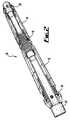
- the kit of parts 10 of Figure 1is assembled together and fitted onto a tubular 22, such as a standard oilfield (API) tubular, as shown in part assembled form in Figure 2 .
- the first and second swellable members 12, 14each have a ridged profile at each end.
- the connector 16also has a ridged profile at each end. The ridged profile at a first end of the connector 16 is pushed into the ridged profile at one end of the first swellable member 12 and the ridged profile at the second, opposing end of the connector is pushed into the ridged at one end of the second swellable member 14.
- the first and second swellable members 12, 14are connected to each other end to end by the connector 16.
- Each of the end connectors 18, 20has a ridged profile, which is pushed onto a respective ridged profile at a free end of the connected swellable members 12, 14.
- the thus joined swellable members, connector and end connectorstogether define a bore through which the tubular 22 extends.
- Figure 3shows the kit of parts 10 installed on the tubular 22 of Figure 2 . More specifically, the ridged profiles of the end connectors 18, 20 and the connector 16 are fully received in the ridged profiles of the swellable members 12, 14 such that these components are properly connected to each other.
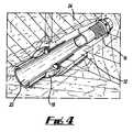
- Figure 4shows a kit of parts comprising a swellable member 12, a connector 16 and an end connector 18 connected together in series, as described above, and fitted on a tubular 22, which extends through a subterranean geological formation 24.
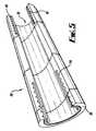
- Figure 5provides a detailed view 30 of the swellable member of Figures 1 to 4 .
- the swellable member 30 of Figure 5is of substantially cylindrical shape and thus defines a bore 32.
- the length of the swellable memberis between about 30.48 cm (1 foot) and about 91.44 cm (3 feet).
- the internal and external diameters of the swellable memberare determined for the application in mind.
- the kit of partsmay comprise a number of such swellable members each having different internal and external diameters and different swellable elastomers so that selective use can be made of the kit of parts depending on the application in mind.
- the swellable memberhas a ridged profile 34, 36, as described above, at each opposing end 38, 40 of the swellable member.
- Each ridged profile 34, 36is defined in a recess formed in an end of the swellable member such that when, for example, a connector 16 is connected to the swellable member 30, the ridged profile of the connector is sandwiched between portions of the swellable member.
- the swellable member 30is formed of a swellable elastomer.
- the swellable member 30may also have a reinforcing member such as Kevlar® (not shown), which is embedded in and extends along the swellable member.
- a swellable elastomeris an elastic material that swells when placed in certain fluids. Swelling is caused by the absorption of fluid. There are two main types of swellable elastomers:
- the membermay comprise ethylene propylene diene monomer rubber (EPDM).
- EPDMethylene propylene diene monomer rubber
- the membermay comprise an N-vinylcarboxylic acid amide-base cross-linked resin and a water swellable urethane in an ethylene-propylene rubber matrix.
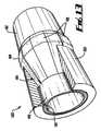
- FIG. 6A detailed view of a connector 50 of the kit of parts of Figures 1 to 4 is provided in Figure 6 .
- the connectoris of generally cylindrical shape such that it defines a bore 52.
- the connectorhas first and second ridged profiles 54, 56 towards respective opposing ends of the connector, as described above.
- First 58 and second 60 flanges(which constitute arresting members) are provided on the connector 50.
- the first flange 58extends radially from the external surface of the connector, i.e. in a direction away from a tubular on which an assembled kit of parts is installed.
- the second flange 60extends radially into the bore 52 of the connector.
- the first and second flangesconstrain the expansion of the swellable member as described below.
- FIG 7AA detailed view of the end connector 70 of the kit of parts of Figures 1 to 4 is provided in Figure 7A .
- the end connectoris of a generally cylindrical shape such that it defines a bore 72.
- a ridged profile 74is provided towards one end of the end connector 70.
- the exterior surface of the opposing end of the connectoris shaped to define a chamfer 76.
- a lip 78is formed on an external surface and on an internal surface of the end connector. Each lip 78 defines a radially extending surface, which constrains the expansion of the swellable member as described below.
- the end connector 70also has a number of bolts that threadedly engage with the end connector at locations spaced apart circumferentially around the external surface of the end connector. The bolts can be used to attach the end connector 70 to a downhole component, such as a casing.
- the end connector 70also comprises a bore member (not shown) that is used to change a diameter of the bore 72 to enable the end connector 70 to be configured for different diameters of tubular.
- the bore membersupports the end connector on the tubular.
- the bore memberhas a tapering portion, and movement of the bore member longitudinally in relation to the end connector causes the bore member to progressively reduce the bore diameter.
- FIG. 7Bshows an end connector in accordance with an alternative embodiment of the invention.
- the end connectorgenerally depicted at 700, is similar to the end connector 70 and shown disposed on a tubular and connected to a swellable member 12.
- the end connector 701differs in that it comprises two components: a mating portion 702 and a retaining portion 703.
- a ridged profile 704is provided towards one end of the mating portion 702, which corresponds to a mating profile in a recess in the swellable member 12.
- the opposing end of the mating portionprovides a bearing surface 705, which abuts a corresponding bearing surface 706 of the retaining portion 703.
- the mating portion 702defines an enlarged bore for receiving the inner parts of the swellable member 12.
- the retaining portion 703also has fixing means in the form of bolts (not shown) that threadedly engage with bores 707 at locations spaced apart circumferentially around the external surface to secure the connector to a tubular.
- the apparatus assembled from the kit of partsWhen used with the end connector 700, the apparatus assembled from the kit of parts will be rotatable on the tubular.
- the mating portion 702is coupled to the apparatus and rotates with the apparatus, and relative to the retaining portion 703.
- the retaining portion 703prevents axial movement of the apparatus.
- Figure 8provides a detailed view of another embodiment of end connector 90.
- the end connector 90 of the embodiment of Figure 8comprises a main body 92, which is as described above in relation to the embodiment of Figure 7 , and a support assembly 94.
- the support assembly 94is shown in more detail in Figure 9 .
- the support assembly 94is configured to abut against an external surface of a swellable member connected to the end connector 92 when the swellable member is in an unexpanded condition and to remain in contact with the external surface as the swellable member expands.
- the support assembly 94comprises a number of concentric support members 96, each of which defines a bore through which a tubular is received.
- One of the support members 96has four support elements 98 which are spaced apart around and attached to the support member 96.
- the support elements 98extend in a longitudinal direction such that they provide for an increase in area of contact between the support assembly and the swellable member.
- Each of the support elements 98comprises four rigid support parts 100 that are configured for movement in relation to each other in a radial direction away from a tubular whereby expansion of the swellable member is accommodated.
- Figure 10shows an assembled kit of parts 120 in use on a tubular.
- the component parts of the assembled kit of parts 120 of Figure 10are the same as those described above with reference to Figure 3 .
- the swellable members 12, 14are exposed to well fluids that cause them to swell. Expansion of the swellable members is directed radially away from the tubular 22 as illustrated by the radially directed arrows. Expansion of the swellable member in a longitudinal direction is arrested by the flanges 58, 60 and lips 78 provided on the connector 16 and the end connectors 18, 20.
- FIG 11shows an embodiment of the present invention, in which an alternative form of end connector 130 is used.
- the end connector 130has a first end connector assembly 132 configured to mate with a mating profile of the swellable member and a second end connector assembly 134 configured to be releasably attached to a tubular as described below.
- the second end connector assembly 134has two end connector parts 136, 138 that are movable in relation to each other between a first disposition that provides for removal of the second end connector assembly from a tubular (as shown in Figure 11 ) and a second disposition in which the second end connector assembly is clamped around a tubular.
- Figure 12shows the second end connector assembly 134 alone when it is in the second disposition.
- the two end connector parts 136, 138move between the first and second dispositions by means of hinges 140 provided along respective edges.
- the opposing non-hinged respective edges of the two end connector parts 136, 138are secured to each other by means of at least one of adhesive, screws, nut and bolts, or the like.
- the first end connector assembly 132 and the second end connector assembly 134have surface profiles 142, 144 that are shaped to inter-engage so that separation of the first and second end connector assemblies from each other is resisted when the second end connector assembly is clamped around a tubular.
- the end connectoralso comprises an anti-slip assembly 150, which is configured to provide resistance to movement of the second end connector assembly on a tubular.
- the anti-slip assembly 150has an anti-slip surface 152 that defines a plurality of radially extending ridges 154, which are configured to bite into the exterior surface.
- the anti-slip assembly 150is disposed between the second end connector assembly and the tubular. To resist separation of the anti-slip assembly and the second end connector assembly from each other, the anti-slip assembly 150 and the second end connector assembly have inter-engaging profiles 156, 158.
- the second end connector assemblyis shaped to provide for passage of wires along the tubular to which the second end connector assembly is attached. This is achieved by providing a longitudinally extending recess on the inner facing surface of the second end connector assembly. Thus, wires can pass between the second end connector assembly and the tubular.
- the swellable member of the previously described embodimentsis configured such that its surface defines a number of apertures (which constitutes an irregularity), each giving access to a bore that extends through the swellable member.
- the provision of boresincreases the surface area of the swellable member that comes into contact with the fluid that causes the swellable member to expand.
- a rate of expansion of the swellable memberis increased.
- the swellable membercomprises a layer disposed over at least a part of its exterior surface. The layer is configured to control access of the at least one predetermined fluid to the exterior surface of the swellable member.
- the layercontrols how the swellable member expands when brought into contact with the at least one predetermined fluid.
- the layeris configured to present a barrier to the at least one predetermined fluid for a predetermined period of time.
- the layerfunctions as a temporary barrier.
- the layeris configured to provide for passage of the fluid through the layer at a predetermined rate.
- the layeris used to reduced a rate at which the swellable member expands when in the presence of the fluid than would be the case were the layer to be absent.
- FIG 13shows an alternative form 180 of a swellable member of the present invention.
- the swellable member 182has a rigid assembly 184, which has three parts: a first collar 186, a plurality of spaced apart fingers 188 and a second collar.
- the first collar 186 and second collarare located within the body of the swellable member 182.
- the first 186 and second collarsare located towards opposing ends of the swellable body and are joined by the plurality of spaced apart fingers 188.
- the fingers 188are spaced apart around the circumference of the swellable member 182.
- the fingers 188follow a path such that at around their mid-point they define the maximum outer diameter of the swellable member. Note that the second collar is not shown in Figure 13 .
- Figure 13shows the swellable member cut away in the vicinity of the first collar 186 but not cut away in the vicinity of the second collar.
- the two collars and the plurality of fingersare integrally formed with each other of a suitable rigid material, such as a metal.
- Each end of the swellable memberdefines a recess 190 having ridges to allow for push fit connection with the connector 16 described above with reference, for example, to Figure 1 .
- the swellable membercan be attached to the tubular on which it is being used, e.g. by means of an adhesive.
- the connection between the connector and the swellable membercan be improved by means of an adhesive.
- the rigid assembly 184defines a maximum outer diameter of the downhole apparatus such that it provide, for example, a stand-off or stabilising function.
- the rigid nature of the rigid assembly 184provides protection for the downhole apparatus.
- the structure of the rigid assembly 184which extends into the body of the swellable member, functions as a skeleton to moderate the effect of shear forces that would, were it not for the rigid assembly 184, be exerted in an uncontrolled manner on the swellable member.
- the spaced apart fingers 188 of the rigid assembly 184can flex such that the maximum outer diameter defined by the rigid assembly 184 reduces. This allows the downhole apparatus of which the swellable member 180 forms part to pass through restrictions. When the downhole apparatus is in the desired location (e.g. where it desired to create a seal) the swellable member is exposed to the predetermined fluid as described above. The swellable member then expands such that it defines the maximum outer diameter of the downhole apparatus.
- kit of partswhen assembled can be used as a packer, which provides advantages over known packers.
- Well constructionnormally involves the placement of metal tubulars that are cemented into the wellbore. A metal tubular is deemed to be properly cemented in place when a predetermined volume of cement has been pumped down the inside of the tubular and fills the annular space between the tubular and the wellbore.
- well packersare then located on the inside of the cemented tubular. This means that known packers are designed to seal well defined spaces that are bounded by smooth surfaces.
- Such known packersare often set in a concentric manner, which means that the packer parts are configured to move uniformly in a radial direction thus allowing for little tolerance of uneven surfaces.
- Well packers formed from kits of parts according to the present inventioncan provide for improved tolerance of uneven surfaces.
- the kit of partsmay be assembled to provide isolation tools for various different applications.
- the primary purpose of the toolmay be to prevent annular flow of particles such as produced sands, and a high pressure seal may not be required
- the kit of partsmay thus be assembled to form a downhole apparatus consisting of a swellable member and two end connectors.
- the kit of partsmay be assembled to form a downhole apparatus terminated at one end by an end connector, and connected to another tool at its opposing end by a connector 50 of the type shown in Figure 6 .
- a packer with high pressure sealing capabilitiesmay be formed from the kit of parts by connecting several swellable members in series. All of the above tools can be assembled from the same kit of components.
- Use of the present inventioncan also provide benefits in meeting requirements to increase well production, efficiency and reliability and to reduce cost. Plugging (i.e. skin damage) in rock formations where cementation and perforation procedures are followed is always a concern in well construction and often the subject of much debate and investment to try and minimise its effects.
- the flexibility and configurability of well packers formed from the present inventioncan help address such problems by eliminating the cementing and perforating operations completely ensuring that formation plugging to kept to a minimum. This is because the swellable member of the present invention allows liner or tubing to be supported without cementing and thus pre-perforated tubing can be used. Furthermore, this application of the present invention eliminates the cost and time involved in cementing and perforating operations.
- the present inventioncan also provide benefits in tubular centralisation.
- the present inventionis manufactured to be gauge with many common open hole diameters, thereby providing maximum stand-off for the swellable member and adjacent tools.
- the inclusion of a swellable elastomermeans that the invention benefits from the integral construction of swellable member and rigid assembly that is robust and high in impact strength. Once wetted with well fluids, the swellable elastomer member allows improved running of well tubulars due to a lower frictional coefficient. This is of benefit in highly deviated wells or extended reach horizontal wells where cumulative resistive drag can prohibit the full installation of metal tubulars. Once the swellable elastomer expands, the radial swelling force can often lift pipe off the low side of horizontal boreholes, providing further centralisation.
Landscapes
- Engineering & Computer Science (AREA)
- Life Sciences & Earth Sciences (AREA)
- Geology (AREA)
- Mining & Mineral Resources (AREA)
- Physics & Mathematics (AREA)
- Environmental & Geological Engineering (AREA)
- Fluid Mechanics (AREA)
- General Life Sciences & Earth Sciences (AREA)
- Geochemistry & Mineralogy (AREA)
- Mechanical Engineering (AREA)
- Geophysics (AREA)
- Earth Drilling (AREA)
- Joints Allowing Movement (AREA)
- Laying Of Electric Cables Or Lines Outside (AREA)
- Pipe Accessories (AREA)
- Filling Or Discharging Of Gas Storage Vessels (AREA)
- Lining Or Joining Of Plastics Or The Like (AREA)
- Branch Pipes, Bends, And The Like (AREA)
- Drilling And Boring (AREA)
- Gasket Seals (AREA)
- Electrical Discharge Machining, Electrochemical Machining, And Combined Machining (AREA)
- Clamps And Clips (AREA)
Description
- The present invention relates to a kit of parts and a method of forming the same which, when assembled, forms downhole apparatus configured to be disposed on a tubular in a downhole environment.
- A well packer provides a seal in an annulus formed between an exterior surface of a tubular and an interior surface of well casing or a wellbore. Known forms of well packers are introduced to the downhole environment in which they are to be used in an unexpanded condition and expanded in-situ to provide the desired seal. In one form, the well packer expands upon coming into contact with a well fluid. In another form, the well packer comprises movable parts that are actuated in-situ to form the seal.
WO 02/20941 WO 2006/121340 ,GB 2411918 GB 2416796 US 2006/124310 ; which is considered the closest prior art, andUS 2006/175065 disclose the application of swellable materials to in-flow control systems.- The present inventor has appreciated that conventional packers have shortcomings and the present invention has been devised in the light of this appreciation. Thus, according to a first aspect of the present invention, there is provided a kit of parts which, when assembled together, forms downhole apparatus configured to be disposed on a tubular in a downhole environment, the kit of parts comprising:
- first and second swellable members which expand upon contact with at least one predetermined fluid, the first and second swellable members having a first mating profile towards a first end and a second mating profile towards a second, opposing end;
- characterised in that the kit of parts further comprises a connector having a mating profile configured to mate with each of the first and second mating profiles of the first and second swellable members such that the connector can be connected to either of the first and second ends of the first or second swellable members and connect the first swellable member to the second swellable member to assemble the downhole apparatus.
- Known well packers and similar such apparatus, such as centralisers and anchors, are normally provided configured ready for use according to specification. Such well packers typically comprise many sub-components of complex form. Thus, assembling a well packer to meet one of a number of specifications can necessitate the keeping a large stock of differently configured sub-components and lengthy and thus expensive assembly procedures. The present invention addresses these problems by providing a kit of parts that can be assembled in the field to meet a particular specification. For example, a series of kits of parts according to the invention can be connected together to provide a string of swellable members where packer coverage of a long length of tubular is required.
- Known well packers and similar such apparatus are normally ordered from a supplier some time in advance of the date for bringing the apparatus into use. Thus, decisions as regards downhole operations, e.g. specific isolation operations, can be subject to a lesser or greater extent to the performance of the apparatus when delivered. This is because known apparatus can be rarely modified on site. The present invention can address such problems by providing for an improvement in flexibility of approach. For example, the configuration of a string of downhole apparatus formed from a plurality of kits of parts according to the invention can be changed on site and more immediately before use in the downhole environment.
- More specifically, the first and second mating profiles may have substantially the same shape.
- Alternatively or in addition, the swellable member may swell upon contact with at least one of: a fluid comprising an aqueous solution; and a polar liquid, e.g. oil.
- Alternatively or in addition, the connector may have first and second mating profiles, each of the first and second mating profiles of the connector being configured to mate with each of the first and second mating profiles of the swellable member. Thus in use, the first mating profile of the connector may be mated with either the first mating profile or the second mating profile of the swellable member. Alternatively, the second mating profile of the connector may be mated with either the first mating profile or the second mating profile of the swellable member. Furthermore, a plurality of kits of parts according to the present invention can be used to connect a plurality of swellable members together, e.g. to provide a greater length of downhole apparatus.
- More specifically, the first mating profile of the connector may be disposed towards a first end of the connector and the second mating profile may be disposed towards a second, opposing end of the connector.
- Alternatively or in addition, the first and second mating profiles of the connector may have substantially the same shape.
- Alternatively or in addition, the first and second mating profiles of the connector may be in line with each other such that, in use, two swellable members connected by means of the connector are in line with each other.
- Alternatively, the first and second mating profiles may be oriented such that, in use, two swellable members connected by means of the connector are out of line with each other.
- More specifically, the first and second mating profiles may be oriented such that, in use, two swellable members connected by means of the connector are disposed at about ninety degrees to each other. Thus, such a connector defines a right angled corner in a string comprising two swellable members connected by means of the connector.
- Alternatively or in addition, a mating profile of the connector may comprise a plurality of ridges extending away from an end of the connector.
- Alternatively or in addition, a mating profile of the swellable member may comprise a plurality of ridges extending away from an end of the swellable member.
- More specifically, the mating profiles of the connector and the swellable member may be configured for a push fit connection of the connector and the swellable member with each other.
- Alternative or in addition, the connector and the swellable member may be connected to each by means of an adhesive.
- Alternatively or in addition, a mating profile of the connector may comprise a threaded profile.
- Alternatively or in addition, a mating profile of the swellable member may comprise a threaded profile.
- Alternatively or in addition, the swellable member may define a mating recess, the mating profile being defined on a surface of the mating recess. Thus, a mating profile of the connector may be received in the mating recess such that the respective mating profiles of the expanding member and the connector mate.
- Alternatively or in addition, the kit of parts may be configured such that a mating profile of one of the connector and the swellable member may upon mating be received in a mating profile of the other of the connector and the swellable member.
- Alternatively or in addition, the swellable member may be of elongate form.
- Alternatively or in addition, the swellable member may define a bore extending therethrough. Thus, the swellable member may be fitted around a tubular.
- More specifically, the swellable member may have a substantially cylindrical shape.
- Alternatively, a cross sectional profile of the swellable member may vary along the swellable member. For example, a diameter of an external surface of the swellable member may change along the swellable member.
- Alternatively or in addition, the swellable member may be configured such that a surface of the swellable member defines at least one irregularity. The at least one irregularity may increase a surface area of the swellable member that may come into contact with the at least one predetermined fluid compared with a swellable member defining an even surface. Thus, a rate of expansion of the swellable member may be increased.
- More specifically, the at least one irregularity may comprise at least one of: a groove, a ridge, an indentation, a protuberance, a roughened area and an aperture to a bore, which extends into the swellable member.
- Where the at least one irregularity is an aperture to a bore, the bore may connect one surface of the swellable member to another surface of the swellable member. Thus, the at least one predetermined fluid may pass though the swellable member by way of the at least one bore from one surface to the other surface.
- Alternatively or in addition, the at least one irregularity may extend substantially longitudinally along the swellable member. For example, where the irregularity is a channel the channel may extend longitudinally along the swellable member.
- Alternatively or in addition, the at least one irregularity may extend around the swellable member. For example, where the irregularity is a channel and the swellable member is of a substantially cylindrical form, the channel may extend circumferentially around the swellable member.
- Alternatively or in addition, the swellable member may comprise a layer disposed over at least a part of an exterior surface of the swellable member, the layer being configured to control access of the at least one predetermined fluid to the exterior surface of the swellable member. Thus, the layer may control how the swellable member expands when brought into contact with the at least one predetermined fluid.
- More specifically, the layer may be configured to present a barrier to the at least one predetermined fluid for a predetermined period of time. Thus, the layer can function as a temporary barrier.
- Alternatively or in addition, the layer may be configured to provide for the at least one predetermined fluid to pass through the layer at a predetermined rate. Thus, the layer can be used to reduced a rate at which the swellable member expands when in the presence of the at least one predetermined fluid than would be the case were the layer to be absent.
- Alternatively or in addition, the kit of parts may further comprise a reinforcing arrangement configured to be disposed on a surface of the swellable member to be presented to the tubular.
- Alternatively or in addition, the swellable member may comprise a reinforcing arrangement. More specifically, the reinforcing arrangement may be embedded in the swellable member. The reinforcing arrangement may comprise at least one of: a metal, a plastics, a composite and individual composite materials, such as carbon-fibre or Kevlar ®.
- Alternatively or in addition, the swellable member may be of elongate form.
- Alternatively or in addition, the swellable member may have a length of between about 30.48 cm (1 foot) and about 91.44 cm (3 feet).
- Alternatively or in addition, the swellable member may comprise ethylene-propylene copolymer cross-linked with at least one of a peroxide and sulphur. Thus, the swellable member may expand upon contact with a polar liquid, such as oil.
- More specifically, the swellable member may comprise ethylene propylene diene monomer rubber (EPDM).
- Alternatively or in addition, the swellable member may comprise at least one of an amide-base cross-linked resin and a water swellable urethane. Thus, the swellable member may expand upon contact with water.
- More specifically, the swellable member may comprise at least one of chloroprene, styrene butadiene and ethylene-propylene rubber.
- Alternatively or in addition, the swellable member may comprise an N-vinylcarboxylic acid amide-base cross-linked resin.
- Alternatively or in addition, the swellable member may expand upon contact with at least one fluid to be found in a downhole environment.
- Alternatively or in addition, the connector may define a bore extending therethrough. Thus, when the connector and the swellable member are connected together they may be fitted around a tubular.
- More specifically, the connector may have a generally cylindrical shape.
- Alternatively or in addition, the connector may comprise an arresting member configured to arrest expansion of the swellable member in a predetermined direction when the kit of parts is assembled and in use. Thus, the arresting member can constrain expansion of the swellable member such that the swellable member expands primarily in a desired direction, for example, away from the tubular on which the downhole apparatus is disposed.
- More specifically, the arresting member may define an arresting surface against which the swellable member abuts when expanding.
- More specifically, the arresting member may extend in a direction substantially away from a tubular on which the downhole apparatus is configured to be disposed and the arresting surface may face an end of the swellable member.
- Alternatively or in addition, the arresting member may extend in a direction substantially towards a tubular on which the downhole apparatus is configured to be disposed and the arresting surface may face an end of the swellable member.
- Alternatively or in addition, the arresting member may comprise at least one flange. One flange may extend in a direction substantially away from a tubular which the downhole apparatus is configured to be disposed and another flange may extend in a direction substantially towards the tubular.
- More specifically, where the connector defines a bore, the bore may extend longitudinally through the connector and the flange may extend radially of the connector.
- Alternatively or in addition, the connector may be formed in part of at least one of: a metal, such as steel, a plastics material, such as nylon, or a composite, such as carbon-fibre reinforced plastics.
- More specifically, the kit of parts may further comprise at least one further connector having features as described above with reference to the connector and at least one further expanding member having features described above with reference to the expanding member.
- In a second form, the kit of parts may comprise an end connector configured to mate with a mating profile of the expanding member.
- More specifically, the end connector may be formed at least in part of at least one of: a metal, such as steel, a plastics material, such as nylon, or a composite, such as carbon-fibre reinforced plastics.
- Alternatively or in addition, the end connector may have a mating profile configured to mate with each of the first and second mating profiles of the swellable member. Thus, for example, the end connector may be used to terminate a string of swellable members on a tubular formed from a plurality of kits of parts according to the present invention.
- More specifically, the mating profile of the end connector may comprise a threaded profile.
- Alternatively or in addition, the end connector may have a chamfered end. More specifically, the chamfered end and the mating profile may be towards opposing ends of the end connector.
- Alternatively or in addition, the end connector and the swellable member may be connected to each other by means of an adhesive.
- Alternatively or in addition, the end connector may be of elongate form.
- Alternatively or in addition, the end connector may define a bore extending therethrough. Thus, the end connector may be fitted around a tubular.
- Alternatively or in addition, the end connector may comprise a first end connector assembly configured to mate with a mating profile of the expanding member and a second end connector assembly configured to be releasably attached to a tubular, the first and second end connector assembly being configured to be releasably attached to each other.
- More specifically, end connector may be configured such that releasably connecting the second end connector assembly to the tubular provides for releasable attachment of the first and second end connector assemblies to each other.
- Alternatively or in addition, the second end connector assembly may comprise two end connector parts movable in relation to each other between a first disposition that provides for removal of the second end connector assembly from the tubular and a second disposition in which the second end connector assembly is attached to the tubular.
- More specifically, the two end connector parts may be movable between the first and second dispositions by hinged movement of the two end connector parts in relation to each other. Thus, the two end connector parts may clamp around the tubular.
- Alternatively or in addition, the two end connector parts may be maintained in the second disposition by securing respective portions of the two end connector parts to each other.
- More specifically, the respective portions of the two end connector parts may be secured to each other by means of at least one of: adhesive, at least one screw, at least one nut and bolt, and the like.
- Alternatively or in addition, the second end connector assembly may be shaped to provide for passage of at least one elongate body, such as a wire or small diameter pipe, along the tubular to which the second end connector assembly is attached such that the at least one elongate body passes between the second end connector assembly and the tubular.
- Alternatively or in addition, the second end connector assembly may be configured to clamp around the first end connector assembly when in the second disposition. Alternatively or in addition, the first and second end connector assemblies may have surface profiles shaped to resist separation of the first and second end connector assemblies from each other when in the second disposition.
- Alternatively or in addition, the end connector may be configured to resist movement of the second end connector assembly in relation to a tubular when the second end connector assembly is attached to the tubular.
- More specifically, the end connector may have an anti-slip surface configured to resist movement across an exterior surface of the tubular.
- More specifically, the anti-slip surface may define a plurality of irregularities, such as circumferentially extending ridges, configured to bite into the exterior surface.
- Alternatively or in addition, the end connector may further comprise an anti-slip assembly, which is configured to provide resistance to movement of the second end connector assembly in relation to the tubular.
- More specifically, the end connector may be configured such that, in use, the anti-slip assembly is disposed between the second end connector assembly and the tubular.
- Alternatively or in addition, the end connector may be configured to resist separation of the anti-slip assembly and the second end connector assembly from each other.
- More specifically, the anti-slip assembly and the second end connector assembly may have inter-engaging profiles.
- More specifically, the end connector may have a substantially cylindrical shape.
- Alternatively or in addition, the end connector may comprise a bore member configured to change a diameter of the bore.
- More specifically, the end connector may be configured to provide for a gradual change in the diameter of the bore.
- Alternatively or in addition, the end connector may be configured such that movement of the bore member in relation to a main body of the end connector provides for the change in diameter.
- More specifically, the bore member and the main body of the end connector may be moved in a longitudinal direction in relation to each other.
- Alternatively or in addition, the bore member may have a tapering portion that movably engages with a main body of the end connector to provide for a change in diameter.
- Alternatively or in addition, the end connector may comprise an end arresting member configured to arrest expansion of the swellable member in a predetermined direction when the kit of parts is assembled and in use. Thus, the end arresting member can constrain expansion of the swellable member such that the swellable member expands primarily in a desired direction, for example, away from a tubular on which the downhole apparatus is disposed.
- More specifically, the end arresting member may define an arresting surface against which the swellable member abuts when expanding.
- More specifically, the end arresting member may extend in a direction substantially away from a tubular on which the downhole apparatus is configured to be disposed and the arresting surface may face an end of the swellable member.
- Alternatively or in addition, the end arresting member may extend in a direction substantially towards a tubular on which the downhole apparatus is configured to be disposed and the arresting surface may face an end of the swellable member.
- Alternatively or in addition, the arresting member may comprise at least one lip. A lip may extend in a direction substantially away from a tubular on which the downhole apparatus is configured to be disposed and another lip may extend in a direction substantially towards the tubular.
- Alternatively or in addition, the end connector may comprise at least one tubular connector configured for providing, at least in part, a connection to a tubular on which the downhole apparatus is disposed when in use.
- More specifically, the end connector may comprise a plurality of tubular connectors spaced apart on the end connector.
- More specifically, the plurality of tubular connectors may be spaced apart around the end connector.
- Alternatively or in addition, the at least one tubular connector may comprise a fastener configured to be connected to a tubular.
- More specifically, the fastener may comprise a bolt that threadedly engages with a corresponding threaded profile formed in the end connector.
- In a third form, the kit of parts may further comprise a support apparatus configured to abut against a surface of the swellable member before and during expansion of the swellable member, the surface against which the supporting apparatus abuts being presented, in use, towards the tubular.
- More specifically, the support apparatus may be configured to abut against a portion of the surface of the swellable member.
- More specifically, the support apparatus may extend along a part of a length of the swellable member.
- Alternatively or in addition, the support apparatus may comprise a plurality of rigid support members that are configured for movement in relation to each other to accommodate expansion of the swellable member.
- More specifically, where the swellable member is of cylindrical form and defines a longitudinally extending bore, the plurality of rigid support members may be moveable in a radial direction.
- Alternatively or in addition, the downhole apparatus further comprises a rigid assembly, the downhole apparatus having a first condition before expansion of the swellable member, in which the rigid assembly defines a maximum outer diameter of the downhole apparatus, and a second condition after expansion of the swellable, in which the swellable member defines a maximum outer diameter of the downhole apparatus.
- More specifically, the downhole apparatus may be configured such that a part of the rigid assembly is surrounded by the swellable member.
- More specifically, the rigid assembly may comprise at least one collar surrounded by the swellable member.
- More specifically, the at least one collar may be proximal to a bore defined by the swellable member and extending through the downhole apparatus.
- Alternatively or in addition, rigid assembly may comprise two collars spaced apart from each other in a longitudinal direction on the downhole apparatus.
- Alternatively or in addition, the rigid assembly may comprise a plurality of spaced apart fingers.
- More specifically, each of the plurality of spaced apart fingers may extend in a longitudinal direction.
- Alternatively or in addition, the fingers may be spaced apart radially around the downhole apparatus.
- Alternatively or in addition, the plurality of fingers may be attached to a collar towards each opposing end of the downhole apparatus.
- Alternatively or in addition, the at least one collar and the plurality of fingers may be integrally formed with each other.
- Alternatively or in addition, the rigid assembly may be formed at least in part of at least one of: a metal, a composite, a rigid plastics, and the like.
- Alternatively or in addition, the swellable member may be attached to the tubular, e.g. by means of an adhesive.
- There may be provided a kit of parts according to the first aspect of the present invention which, when assembled together, forms downhole apparatus configured to provide a seal between the tubular and another wellbore component. Thus, the present invention may be used to isolate a part of a well. Seals are often used in downhole environments to contain and/or control well fluids. Such well fluids may be flowing to or from a subterranean geological formation or may be flowing to or from the surface. Isolation can be used to control the flow of well fluids or prevent undesired mixing of different well fluids.
- More specifically, the other wellbore component may be one of: a casing and an inside surface of a wellbore.
- There may be provided a kit of parts according to the first aspect of the present invention which, when assembled together, forms downhole apparatus configured to provide stand-off between a tubular and a wellbore surface. Thus, the present invention may take the form of a centraliser when assembled.
- In use, centralisers perform important functions in downhole environments. Centralisers may, for example, ensure that a tubular does not come into contact with a wellbore surface. This function is of particular importance when a tubular is being cemented into a wellbore. This is because a poorly centralised tubular can lead to channelling, i.e. the failure to form a cement bond around the entire circumference of the annular space between the tubular and the wellbore. This results in poor isolation of well fluids, which can ultimately lead to uncontrollable flow of well fluids to the surface or to subterranean geological formations.
- There may be provided a kit of parts according to the first aspect of the present invention which, when assembled together, forms downhole apparatus configured to limit movement of a tubular in relation to a wellbore surface.
- Tubular anchors are employed in downhole environments to limit movement of a tubular in relation to a wellbore. Movement of a tubular can be caused by mechanical loading of the tubular or hydraulic piston forces. In addition, a temperature change across a well can cause expansion or contraction of a tubular and thereby cause movement of the tubular in relation to the well.
- There may be provided oil or gas recovery or exploration apparatus comprising downhole apparatus assembled from the kit of parts according to the first aspect of the present invention.
- According to a second aspect of the present invention, there is provided a method of assembling a downhole apparatus, the method comprising:
- providing first and second swellable members, the first and second swellable members expanding upon contact with at least one predetermined fluid and having a first mating profile towards a first end and a second mating profile towards a second, opposing end;
- providing a connector having a mating profile configured to mate with each of the first and second mating profiles of the first and second swellable members; and
- characterised in that the method comprises connecting the first swellable member to the second swellable members by mating the connector with either of the first and second ends of each of the first and second swellable members to thereby assemble the downhole apparatus.
- There may be provided downhole apparatus configured to be disposed on a tubular in a downhole environment, the downhole apparatus comprising a swellable member which expands upon contact with at least one predetermined fluid, in which the swellable member is configured such that a surface of the swellable member defines at least one irregularity.
- In use, the at least one irregularity increases a surface area of the swellable member that comes into contact with the at least one predetermined fluid compared with a swellable member defining an even surface, e.g. a swellable member of substantially cylindrical form having an even surface. Thus, a rate of expansion of the swellable member may be increased.
- More specifically, the at least one irregularity may comprise at least one of: a groove, a ridge, an indentation, a protuberance, a roughened area and an aperture to a bore, which extend into the swellable member.
- Where the at least one irregularity is an aperture to a bore, the bore may connect one surface of the swellable member to another surface of the swellable member. Thus, the at least one predetermined fluid may pass though the swellable member by way of the at least one bore from one surface to the other surface.
- Alternatively or in addition, the at least one irregularity may extend substantially longitudinally along the swellable member. For example, where the irregularity is a channel the channel may extend longitudinally along the swellable member.
- Alternatively or in addition, the at least one irregularity may extend around the swellable member. For example, where the irregularity is a channel and the swellable member is of a substantially cylindrical form, the channel may extend circumferentially around the swellable member.
- Alternatively or in addition, the swellable member may form part of a kit of parts which, when assembled together forms the downhole apparatus.
- More specifically, the swellable member may have a first mating profile towards a first end and a second mating profile towards a second, opposing end, and the kit of parts may further comprise a connector having a mating profile configured to mate with each of the first and second mating profiles of the swellable member such that the connector can be connected to either of the first and second ends of the swellable member.
- There may be provided downhole apparatus configured to be disposed on a tubular in a downhole environment, the downhole apparatus comprising: a swellable member which expands upon contact with at least one predetermined fluid; and a rigid assembly, the downhole apparatus having a first condition before expansion of the swellable member, in which the rigid assembly defines a maximum outer diameter of the downhole apparatus, and a second condition after expansion of the swellable, in which the swellable member defines a maximum outer diameter of the downhole apparatus.
- When the downhole assembly is in use downhole in the first condition the rigid assembly can provide stand-off protection. When the downhole assembly is in the second condition, the swellable member is expanded to, for example, provide isolation.
- More specifically, the downhole apparatus may be configured such that a part of the rigid assembly is surrounded by the swellable member.
- More specifically, the rigid assembly may comprise at least one collar surrounded by the swellable member.
- More specifically, the at least one collar may be proximal to a bore defined by the swellable member and extending through the downhole apparatus.
- Alternatively or in addition, rigid assembly may comprise two collars spaced apart from each other in a longitudinal direction on the downhole apparatus.
- Alternatively or in addition, the rigid assembly may comprise a plurality of spaced apart fingers.
- More specifically, each of the plurality of spaced apart fingers may extend in a longitudinal direction.
- Alternatively or in addition, the fingers may be spaced apart radially around the downhole apparatus.
- Alternatively or in addition, the plurality of fingers may be attached to a collar towards each opposing end of the downhole apparatus.
- Alternatively or in addition, the at least one collar and the plurality of fingers may be integrally formed with each other.
- Alternatively or in addition, the rigid assembly may be formed at least in part of at least one of: a metal, a composite, a rigid plastics, and the like.
- According to a third aspect of the invention there is provided a well packer assembled from the kit of parts according to the first aspect of the invention.
- According to a fourth aspect of the invention there is provided a well installation comprising a downhole apparatus assembled from the kit of parts according to the first aspect of the invention.
- Further features and advantages of the present invention will become apparent from the following specific description, which is given by way of example only and with reference to the accompanying drawings, in which:
Figure 1 shows a kit of parts according to an embodiment of the present invention;Figure 2 shows the kit of parts ofFigure 1 partially installed on a tubular;Figure 3 shows the kit of parts ofFigure 1 installed on a tubular;Figure 4 shows the kit of parts ofFigure 1 assembled and in situ in a downhole environment;Figure 5 provides a detailed view of a swellable member of the kit of parts ofFigure 1 ;Figure 6 provides a detailed view of a connector of the kit of parts in accordance with an embodiment of the invention;Figure 7A provides a detailed view of an end connector of the kit of parts ofFigure 1 ;Figure 7B provides a detailed view of part of a longitudinal section through an alternative end connector in an assembled condition;Figure 8 provides a detailed view of an alternative end connector which forms part of an alternative embodiment of the invention;Figure 9 provides a view of part of the embodiment ofFigure 8 ;Figure 10 shows an assembled kit of parts when the swellable member is being activated.Figure 11 shows an embodiment of the present invention, in which an alternative form of end connector is used;Figure 12 shows the embodiment ofFigure 11 in its clamped condition; andFigure 13 shows an alternative form of a swellable member of the present invention.Figure 1 shows a kit ofparts 10 according to the present invention having a firstswellable member 12, a secondswellable member 14, aconnector 16, afirst end connector 18 and asecond end connector 20. Theconnector 16 is configured to connect the twoswellable members second end connectors swellable members swellable members second end connectors connector 16 are of generally cylindrical form and thus define a bore extending longitudinally therethrough.- The kit of
parts 10 ofFigure 1 is assembled together and fitted onto a tubular 22, such as a standard oilfield (API) tubular, as shown in part assembled form inFigure 2 . The first and secondswellable members connector 16 also has a ridged profile at each end. The ridged profile at a first end of theconnector 16 is pushed into the ridged profile at one end of the firstswellable member 12 and the ridged profile at the second, opposing end of the connector is pushed into the ridged at one end of the secondswellable member 14. Thus, the first and secondswellable members connector 16. Each of theend connectors swellable members Figure 3 shows the kit ofparts 10 installed on the tubular 22 ofFigure 2 . More specifically, the ridged profiles of theend connectors connector 16 are fully received in the ridged profiles of theswellable members Figure 4 shows a kit of parts comprising aswellable member 12, aconnector 16 and anend connector 18 connected together in series, as described above, and fitted on a tubular 22, which extends through a subterraneangeological formation 24.Figure 5 provides adetailed view 30 of the swellable member ofFigures 1 to 4 . Theswellable member 30 ofFigure 5 is of substantially cylindrical shape and thus defines abore 32. The length of the swellable member is between about 30.48 cm (1 foot) and about 91.44 cm (3 feet). The internal and external diameters of the swellable member are determined for the application in mind. Indeed, the kit of parts may comprise a number of such swellable members each having different internal and external diameters and different swellable elastomers so that selective use can be made of the kit of parts depending on the application in mind. Returning toFigure 5 , the swellable member has a ridgedprofile opposing end profile connector 16 is connected to theswellable member 30, the ridged profile of the connector is sandwiched between portions of the swellable member.- The
swellable member 30 is formed of a swellable elastomer. Theswellable member 30 may also have a reinforcing member such as Kevlar® (not shown), which is embedded in and extends along the swellable member. A swellable elastomer is an elastic material that swells when placed in certain fluids. Swelling is caused by the absorption of fluid. There are two main types of swellable elastomers: - ■ those that swell in oil; and
- ■ those that swelling in an aqueous solution.
- Where the swellable member swells in oil, the member may comprise ethylene propylene diene monomer rubber (EPDM). Where the swellable member swells in water, the member may comprise an N-vinylcarboxylic acid amide-base cross-linked resin and a water swellable urethane in an ethylene-propylene rubber matrix.
- A detailed view of a
connector 50 of the kit of parts ofFigures 1 to 4 is provided inFigure 6 . The connector is of generally cylindrical shape such that it defines abore 52. The connector has first and secondridged profiles connector 50. Thefirst flange 58 extends radially from the external surface of the connector, i.e. in a direction away from a tubular on which an assembled kit of parts is installed. Thesecond flange 60 extends radially into thebore 52 of the connector. The first and second flanges constrain the expansion of the swellable member as described below. - A detailed view of the
end connector 70 of the kit of parts ofFigures 1 to 4 is provided inFigure 7A . The end connector is of a generally cylindrical shape such that it defines abore 72. A ridgedprofile 74 is provided towards one end of theend connector 70. The exterior surface of the opposing end of the connector is shaped to define achamfer 76. Alip 78 is formed on an external surface and on an internal surface of the end connector. Eachlip 78 defines a radially extending surface, which constrains the expansion of the swellable member as described below. Theend connector 70 also has a number of bolts that threadedly engage with the end connector at locations spaced apart circumferentially around the external surface of the end connector. The bolts can be used to attach theend connector 70 to a downhole component, such as a casing. - In an alternative embodiment, the
end connector 70 also comprises a bore member (not shown) that is used to change a diameter of thebore 72 to enable theend connector 70 to be configured for different diameters of tubular. The bore member supports the end connector on the tubular. In one variation, the bore member has a tapering portion, and movement of the bore member longitudinally in relation to the end connector causes the bore member to progressively reduce the bore diameter. Figure 7B shows an end connector in accordance with an alternative embodiment of the invention. The end connector, generally depicted at 700, is similar to theend connector 70 and shown disposed on a tubular and connected to aswellable member 12. However, the end connector 701 differs in that it comprises two components: amating portion 702 and a retainingportion 703. Aridged profile 704 is provided towards one end of themating portion 702, which corresponds to a mating profile in a recess in theswellable member 12. The opposing end of the mating portion provides abearing surface 705, which abuts a correspondingbearing surface 706 of the retainingportion 703. Themating portion 702 defines an enlarged bore for receiving the inner parts of theswellable member 12. The retainingportion 703 also has fixing means in the form of bolts (not shown) that threadedly engage withbores 707 at locations spaced apart circumferentially around the external surface to secure the connector to a tubular.- When used with the
end connector 700, the apparatus assembled from the kit of parts will be rotatable on the tubular. Themating portion 702 is coupled to the apparatus and rotates with the apparatus, and relative to the retainingportion 703. The retainingportion 703 prevents axial movement of the apparatus. Figure 8 provides a detailed view of another embodiment ofend connector 90. Theend connector 90 of the embodiment ofFigure 8 comprises amain body 92, which is as described above in relation to the embodiment ofFigure 7 , and asupport assembly 94. Thesupport assembly 94 is shown in more detail inFigure 9 . Thesupport assembly 94 is configured to abut against an external surface of a swellable member connected to theend connector 92 when the swellable member is in an unexpanded condition and to remain in contact with the external surface as the swellable member expands. More specifically, thesupport assembly 94 comprises a number ofconcentric support members 96, each of which defines a bore through which a tubular is received. One of thesupport members 96 has foursupport elements 98 which are spaced apart around and attached to thesupport member 96. Thesupport elements 98 extend in a longitudinal direction such that they provide for an increase in area of contact between the support assembly and the swellable member. Each of thesupport elements 98 comprises fourrigid support parts 100 that are configured for movement in relation to each other in a radial direction away from a tubular whereby expansion of the swellable member is accommodated.Figure 10 shows an assembled kit ofparts 120 in use on a tubular. The component parts of the assembled kit ofparts 120 ofFigure 10 are the same as those described above with reference toFigure 3 . In use, theswellable members flanges lips 78 provided on theconnector 16 and theend connectors Figure 11 shows an embodiment of the present invention, in which an alternative form ofend connector 130 is used. Theend connector 130 has a firstend connector assembly 132 configured to mate with a mating profile of the swellable member and a secondend connector assembly 134 configured to be releasably attached to a tubular as described below. The secondend connector assembly 134 has twoend connector parts Figure 11 ) and a second disposition in which the second end connector assembly is clamped around a tubular.Figure 12 shows the secondend connector assembly 134 alone when it is in the second disposition. Referring again toFigure 11 , the twoend connector parts hinges 140 provided along respective edges. The opposing non-hinged respective edges of the twoend connector parts - The first
end connector assembly 132 and the secondend connector assembly 134 havesurface profiles - The end connector also comprises an
anti-slip assembly 150, which is configured to provide resistance to movement of the second end connector assembly on a tubular. Theanti-slip assembly 150 has ananti-slip surface 152 that defines a plurality of radially extendingridges 154, which are configured to bite into the exterior surface. In use, theanti-slip assembly 150 is disposed between the second end connector assembly and the tubular. To resist separation of the anti-slip assembly and the second end connector assembly from each other, theanti-slip assembly 150 and the second end connector assembly haveinter-engaging profiles - In an un-illustrated form of the embodiment of
Figures 11 and 12 , the second end connector assembly is shaped to provide for passage of wires along the tubular to which the second end connector assembly is attached. This is achieved by providing a longitudinally extending recess on the inner facing surface of the second end connector assembly. Thus, wires can pass between the second end connector assembly and the tubular. - In a further un-illustrated embodiment, the swellable member of the previously described embodiments is configured such that its surface defines a number of apertures (which constitutes an irregularity), each giving access to a bore that extends through the swellable member. The provision of bores increases the surface area of the swellable member that comes into contact with the fluid that causes the swellable member to expand. Thus, a rate of expansion of the swellable member is increased. Furthermore, the swellable member comprises a layer disposed over at least a part of its exterior surface. The layer is configured to control access of the at least one predetermined fluid to the exterior surface of the swellable member. Thus, the layer controls how the swellable member expands when brought into contact with the at least one predetermined fluid. More specifically, the layer is configured to present a barrier to the at least one predetermined fluid for a predetermined period of time. Thus, the layer functions as a temporary barrier. Also, the layer is configured to provide for passage of the fluid through the layer at a predetermined rate. Thus, the layer is used to reduced a rate at which the swellable member expands when in the presence of the fluid than would be the case were the layer to be absent.
Figure 13 shows analternative form 180 of a swellable member of the present invention. Theswellable member 182 has arigid assembly 184, which has three parts: afirst collar 186, a plurality of spaced apartfingers 188 and a second collar. Thefirst collar 186 and second collar are located within the body of theswellable member 182. The first 186 and second collars are located towards opposing ends of the swellable body and are joined by the plurality of spaced apartfingers 188. Thefingers 188 are spaced apart around the circumference of theswellable member 182. Thefingers 188 follow a path such that at around their mid-point they define the maximum outer diameter of the swellable member. Note that the second collar is not shown inFigure 13 . This is becauseFigure 13 shows the swellable member cut away in the vicinity of thefirst collar 186 but not cut away in the vicinity of the second collar. The two collars and the plurality of fingers are integrally formed with each other of a suitable rigid material, such as a metal.- Each end of the swellable member defines a
recess 190 having ridges to allow for push fit connection with theconnector 16 described above with reference, for example, toFigure 1 . - In the above described embodiments, addition, the swellable member can be attached to the tubular on which it is being used, e.g. by means of an adhesive. Also, the connection between the connector and the swellable member can be improved by means of an adhesive.
- In use, downhole apparatus comprising the swellable member of
Figure 13 is introduced downhole in a first condition before expansion of the swellable member. Thus and as shown inFigure 13 , therigid assembly 184 defines a maximum outer diameter of the downhole apparatus such that it provide, for example, a stand-off or stabilising function. The rigid nature of therigid assembly 184 provides protection for the downhole apparatus. Also, the structure of therigid assembly 184, which extends into the body of the swellable member, functions as a skeleton to moderate the effect of shear forces that would, were it not for therigid assembly 184, be exerted in an uncontrolled manner on the swellable member. The spaced apartfingers 188 of therigid assembly 184 can flex such that the maximum outer diameter defined by therigid assembly 184 reduces. This allows the downhole apparatus of which theswellable member 180 forms part to pass through restrictions. When the downhole apparatus is in the desired location (e.g. where it desired to create a seal) the swellable member is exposed to the predetermined fluid as described above. The swellable member then expands such that it defines the maximum outer diameter of the downhole apparatus. - Applications of the kit of parts will now be described. The kit of parts when assembled can be used as a packer, which provides advantages over known packers. Well construction normally involves the placement of metal tubulars that are cemented into the wellbore. A metal tubular is deemed to be properly cemented in place when a predetermined volume of cement has been pumped down the inside of the tubular and fills the annular space between the tubular and the wellbore. According to known practice, well packers are then located on the inside of the cemented tubular. This means that known packers are designed to seal well defined spaces that are bounded by smooth surfaces. Such known packers are often set in a concentric manner, which means that the packer parts are configured to move uniformly in a radial direction thus allowing for little tolerance of uneven surfaces. Well packers formed from kits of parts according to the present invention can provide for improved tolerance of uneven surfaces.
- The kit of parts may be assembled to provide isolation tools for various different applications. For example, in some scenarios the primary purpose of the tool may be to prevent annular flow of particles such as produced sands, and a high pressure seal may not be required, The kit of parts may thus be assembled to form a downhole apparatus consisting of a swellable member and two end connectors. Alternatively, the kit of parts may be assembled to form a downhole apparatus terminated at one end by an end connector, and connected to another tool at its opposing end by a
connector 50 of the type shown inFigure 6 . In another application a packer with high pressure sealing capabilities may be formed from the kit of parts by connecting several swellable members in series. All of the above tools can be assembled from the same kit of components. - Use of the present invention can also provide benefits in meeting requirements to increase well production, efficiency and reliability and to reduce cost. Plugging (i.e. skin damage) in rock formations where cementation and perforation procedures are followed is always a concern in well construction and often the subject of much debate and investment to try and minimise its effects. The flexibility and configurability of well packers formed from the present invention can help address such problems by eliminating the cementing and perforating operations completely ensuring that formation plugging to kept to a minimum. This is because the swellable member of the present invention allows liner or tubing to be supported without cementing and thus pre-perforated tubing can be used. Furthermore, this application of the present invention eliminates the cost and time involved in cementing and perforating operations.
- Use of the present invention can also provide benefits in tubular centralisation. The present invention is manufactured to be gauge with many common open hole diameters, thereby providing maximum stand-off for the swellable member and adjacent tools. The inclusion of a swellable elastomer means that the invention benefits from the integral construction of swellable member and rigid assembly that is robust and high in impact strength. Once wetted with well fluids, the swellable elastomer member allows improved running of well tubulars due to a lower frictional coefficient. This is of benefit in highly deviated wells or extended reach horizontal wells where cumulative resistive drag can prohibit the full installation of metal tubulars. Once the swellable elastomer expands, the radial swelling force can often lift pipe off the low side of horizontal boreholes, providing further centralisation.
- The present invention offers the following advantages:
- i) The kit of parts can be adapted to and installed on any well tubular, which may be formed of plastics, composite or metal. The tubulars with which the invention can be used include: tubing, casing, sand screen, gravel pack, work strings, slick joints, coiled tubing and pump sucker rods.
- ii) The use of a swellable member that expands upon contact with well fluids provides for activation of the swellable member without downhole intervention.
- iii) A series of swellable members can be set in a non-concentric manner and irrespective of their orientation.
- iv) The swellable members can be set in irregular, non-circular and non-linear formations or downhole structures.
- v) The kit of parts can be installed in existing tubulars without the need for specialised assembly techniques or equipment.
- vi) The kit of parts can normally be assembled and installed without specially trained personnel.
- vii) Tubulars and formations of different shapes and diameters can be accommodated.
- viii) The downhole apparatus can be configured to control the rate of expansion of the swellable member.
- ix) The downhole apparatus when assembled from the kit of parts provides for integral self-centralisation when in use.
- x) The kit of parts can be assembled at the last minute to take account of changing specification requirements.
- xi) The kit of parts provides for the assembly of downhole apparatus that can have significantly reduced frictional coefficients than conventional downhole apparatus.
Claims (15)
- A kit of parts (10) which, when assembled together, forms a downhole apparatus configured to be disposed on a tubular (22) in a downhole environment, the kit of parts comprising:first and second swellable members (12, 14) which expand upon contact with at least one predetermined fluid, the first and second swellable members having a first mating profile (34) towards a first end (38) and a second mating profile (36) towards a second, opposing end (40);characterised in that the kit of parts further comprises a connector (16, 50) having a mating profile configured to mate with each of the first and second mating profiles of the first and second swellable members (12, 14) such that the connector can be connected to either of the first and second ends of the first or second swellable members and connect the first swellable member to the second swellable member to assemble the downhole apparatus.
- A kit of parts according to any preceding claim, in which the connector (50) has first (54) and second (56) mating profiles, each of the first and second mating profiles of the connector being configured to mate with each of the first and second mating profiles (34, 36) of the first or second swellable members (12, 14).
- A kit of parts according to any preceding claim, in which mating profiles of the connector and the first or second swellable members are configured for a push fit connection of the connector and the first or second swellable members with each other.
- A kit of parts according to any preceding claim, in which a mating profile of the connector comprises a threaded profile.
- A kit of parts according to any preceding claim, in which the first or second swellable members define a mating recess, the mating profiles (34, 36) being defined on a surface of the mating recess.
- A kit of parts according to any preceding claim, in which the kit of parts further comprises a reinforcing arrangement configured to be disposed on a surface of the first or second swellable members to be presented to the tubular.
- A kit of parts according to claim 6, in which the reinforcing arrangement is embedded in the first or second swellable members.
- A kit of parts according to any preceding claim, in which the connector (50) comprises an arresting member (58) configured to arrest expansion of the first or second swellable members and extends in a direction substantially away from a tubular on which the downhole apparatus is configured to be disposed and wherein the arresting surface faces an end of the first or second swellable members.
- A kit of parts according to any of claims 1 to 7, in which the connector (50) comprises an arresting member (60) configured to arrest expansion of the first or second swellable members and extends in a direction substantially towards a tubular on which the downhole apparatus is configured to be disposed and wherein the arresting surface faces an end of the first or second swellable members.
- A kit of parts according to any preceding claim, in which the kit of parts comprises an end connector (18, 20, 70, 90, 700) configured to mate with a mating profile (34, 36) of the first or second swellable members (12, 14).
- A kit of parts according to claim 10, in which the end connector (700) comprises a mating portion (702) configured to mate with the first or second swellable members and a retaining portion (703) configured to be attached to a tubular.
- A well packer assembled from the kit of parts according to any preceding claim.
- A well installation comprising a downhole apparatus assembled from the kit of parts of any of claims 1 to 11.
- A method of assembling a downhole apparatus, the method comprising:providing first and second swellable members, the first and second swellable members expanding upon contact with at least one predetermined fluid and having a first mating profile (34) towards a first end (38) and a second mating profile (36) towards a second, opposing end (40);providing a connector having a mating profile configured to mate with each of the first and second mating profiles of the first and second swellable members; andcharacterised in that the method comprises connecting the first swellable member to the second swellable members by mating the connector with either of the first and second ends of each of the first and second swellable members to thereby assemble the downhole apparatus.
- The method of assembling a downhole apparatus according to claim 14, wherein the method comprises mating the mating profiles of the connector with the first or second swellable members by a push fit connection.
Priority Applications (1)
| Application Number | Priority Date | Filing Date | Title |
|---|---|---|---|
| PL11187347TPL2423430T3 (en) | 2006-11-21 | 2007-11-21 | Downhole apparatus and method |
Applications Claiming Priority (2)
| Application Number | Priority Date | Filing Date | Title |
|---|---|---|---|
| GB0623138AGB2444060B (en) | 2006-11-21 | 2006-11-21 | Downhole apparatus and method |
| EP07824657.6AEP2084365B1 (en) | 2006-11-21 | 2007-11-21 | Downhole apparatus and method |
Related Parent Applications (3)
| Application Number | Title | Priority Date | Filing Date |
|---|---|---|---|
| EP07824657.6Division | 2007-11-21 | ||
| EP07824657.6ADivisionEP2084365B1 (en) | 2006-11-21 | 2007-11-21 | Downhole apparatus and method |
| EP07824657.6ADivision-IntoEP2084365B1 (en) | 2006-11-21 | 2007-11-21 | Downhole apparatus and method |
Publications (2)
| Publication Number | Publication Date |
|---|---|
| EP2423430A1 EP2423430A1 (en) | 2012-02-29 |
| EP2423430B1true EP2423430B1 (en) | 2014-01-15 |
Family
ID=37605608
Family Applications (10)
| Application Number | Title | Priority Date | Filing Date |
|---|---|---|---|
| EP11187347.7ANot-in-forceEP2423430B1 (en) | 2006-11-21 | 2007-11-21 | Downhole apparatus and method |
| EP11182825AWithdrawnEP2402552A1 (en) | 2006-11-21 | 2007-11-21 | Downhole apparatus and method |
| EP07848387AWithdrawnEP2084362A1 (en) | 2006-11-21 | 2007-11-21 | Down hole apparatus and method |
| EP07848390AWithdrawnEP2084363A1 (en) | 2006-11-21 | 2007-11-21 | Downhole apparatus and method |
| EP07848389AWithdrawnEP2084366A1 (en) | 2006-11-21 | 2007-11-21 | Downhole apparatus and support structure therefor |
| EP11183010AWithdrawnEP2402553A1 (en) | 2006-11-21 | 2007-11-21 | Downhole apparatus and support structure therefor |
| EP11182828AWithdrawnEP2402549A1 (en) | 2006-11-21 | 2007-11-21 | Downhole apparatus and method |
| EP07824657.6ANot-in-forceEP2084365B1 (en) | 2006-11-21 | 2007-11-21 | Downhole apparatus and method |
| EP11182827AWithdrawnEP2402548A1 (en) | 2006-11-21 | 2007-11-21 | Downhole apparatus and method |
| EP11182826AWithdrawnEP2402547A1 (en) | 2006-11-21 | 2007-11-21 | Downhole apparatus and method |
Family Applications After (9)
| Application Number | Title | Priority Date | Filing Date |
|---|---|---|---|
| EP11182825AWithdrawnEP2402552A1 (en) | 2006-11-21 | 2007-11-21 | Downhole apparatus and method |
| EP07848387AWithdrawnEP2084362A1 (en) | 2006-11-21 | 2007-11-21 | Down hole apparatus and method |
| EP07848390AWithdrawnEP2084363A1 (en) | 2006-11-21 | 2007-11-21 | Downhole apparatus and method |
| EP07848389AWithdrawnEP2084366A1 (en) | 2006-11-21 | 2007-11-21 | Downhole apparatus and support structure therefor |
| EP11183010AWithdrawnEP2402553A1 (en) | 2006-11-21 | 2007-11-21 | Downhole apparatus and support structure therefor |
| EP11182828AWithdrawnEP2402549A1 (en) | 2006-11-21 | 2007-11-21 | Downhole apparatus and method |
| EP07824657.6ANot-in-forceEP2084365B1 (en) | 2006-11-21 | 2007-11-21 | Downhole apparatus and method |
| EP11182827AWithdrawnEP2402548A1 (en) | 2006-11-21 | 2007-11-21 | Downhole apparatus and method |
| EP11182826AWithdrawnEP2402547A1 (en) | 2006-11-21 | 2007-11-21 | Downhole apparatus and method |
Country Status (8)
| Country | Link |
|---|---|
| US (8) | US7896085B2 (en) |
| EP (10) | EP2423430B1 (en) |
| BR (4) | BRPI0719097A2 (en) |
| CA (4) | CA2668678C (en) |
| GB (7) | GB2444060B (en) |
| NO (4) | NO340362B1 (en) |
| PL (1) | PL2423430T3 (en) |
| WO (1) | WO2008062178A1 (en) |
Families Citing this family (127)
| Publication number | Priority date | Publication date | Assignee | Title |
|---|---|---|---|---|
| US20090107684A1 (en) | 2007-10-31 | 2009-04-30 | Cooke Jr Claude E | Applications of degradable polymers for delayed mechanical changes in wells |
| US20040231845A1 (en) | 2003-05-15 | 2004-11-25 | Cooke Claude E. | Applications of degradable polymers in wells |
| GB2444060B (en)* | 2006-11-21 | 2008-12-17 | Swelltec Ltd | Downhole apparatus and method |
| GB2459457B (en) | 2008-04-22 | 2012-05-09 | Swelltec Ltd | Downhole apparatus and method |
| US7841409B2 (en)* | 2008-08-29 | 2010-11-30 | Halliburton Energy Services, Inc. | Sand control screen assembly and method for use of same |
| US7841417B2 (en)* | 2008-11-24 | 2010-11-30 | Halliburton Energy Services, Inc. | Use of swellable material in an annular seal element to prevent leakage in a subterranean well |
| US9587475B2 (en) | 2008-12-23 | 2017-03-07 | Frazier Ball Invention, LLC | Downhole tools having non-toxic degradable elements and their methods of use |
| US9506309B2 (en) | 2008-12-23 | 2016-11-29 | Frazier Ball Invention, LLC | Downhole tools having non-toxic degradable elements |
| US8496052B2 (en) | 2008-12-23 | 2013-07-30 | Magnum Oil Tools International, Ltd. | Bottom set down hole tool |
| US8899317B2 (en) | 2008-12-23 | 2014-12-02 | W. Lynn Frazier | Decomposable pumpdown ball for downhole plugs |
| US8079413B2 (en) | 2008-12-23 | 2011-12-20 | W. Lynn Frazier | Bottom set downhole plug |
| US9217319B2 (en) | 2012-05-18 | 2015-12-22 | Frazier Technologies, L.L.C. | High-molecular-weight polyglycolides for hydrocarbon recovery |
| GB0905819D0 (en)* | 2009-04-03 | 2009-05-20 | Swellfix Bv | Seal assembly |
| US9562415B2 (en) | 2009-04-21 | 2017-02-07 | Magnum Oil Tools International, Ltd. | Configurable inserts for downhole plugs |
| US9163477B2 (en) | 2009-04-21 | 2015-10-20 | W. Lynn Frazier | Configurable downhole tools and methods for using same |
| US9062522B2 (en) | 2009-04-21 | 2015-06-23 | W. Lynn Frazier | Configurable inserts for downhole plugs |
| US9109428B2 (en) | 2009-04-21 | 2015-08-18 | W. Lynn Frazier | Configurable bridge plugs and methods for using same |
| US9127527B2 (en) | 2009-04-21 | 2015-09-08 | W. Lynn Frazier | Decomposable impediments for downhole tools and methods for using same |
| US9181772B2 (en) | 2009-04-21 | 2015-11-10 | W. Lynn Frazier | Decomposable impediments for downhole plugs |
| US7963321B2 (en)* | 2009-05-15 | 2011-06-21 | Tam International, Inc. | Swellable downhole packer |
| US8474524B2 (en)* | 2009-05-21 | 2013-07-02 | Schlumberger Technology Corporation | Anti-extrusion packer system |
| US20100300675A1 (en)* | 2009-06-02 | 2010-12-02 | Baker Hughes Incorporated | Permeability flow balancing within integral screen joints |
| GB0914416D0 (en)* | 2009-08-18 | 2009-09-30 | Rubberatkins Ltd | Pressure control device |
| US8474525B2 (en)* | 2009-09-18 | 2013-07-02 | David R. VAN DE VLIERT | Geothermal liner system with packer |
| CN102108844B (en)* | 2009-12-28 | 2015-04-01 | 思达斯易能源技术(集团)有限公司 | Packer fixing ring and oil/water self-expandable packer with same |
| US8281854B2 (en)* | 2010-01-19 | 2012-10-09 | Baker Hughes Incorporated | Connector for mounting screen to base pipe without welding or swaging |
| GB201004045D0 (en)* | 2010-03-11 | 2010-04-28 | Tendeka Bv | Fully bonded end rings |
| US8397802B2 (en) | 2010-06-07 | 2013-03-19 | Weatherford/Lamb, Inc. | Swellable packer slip mechanism |
| US8997854B2 (en)* | 2010-07-23 | 2015-04-07 | Weatherford Technology Holdings, Llc | Swellable packer anchors |
| NO334036B1 (en)* | 2010-08-06 | 2013-11-25 | Roxar Flow Measurement As | Clamp |
| US20120073834A1 (en)* | 2010-09-28 | 2012-03-29 | Weatherford/Lamb, Inc. | Friction Bite with Swellable Elastomer Elements |
| US20120139184A1 (en)* | 2010-12-07 | 2012-06-07 | Petrohawk Properties, Lp | Dual Seal Tubing Hanger |
| US8596369B2 (en)* | 2010-12-10 | 2013-12-03 | Halliburton Energy Services, Inc. | Extending lines through, and preventing extrusion of, seal elements of packer assemblies |
| US8662161B2 (en)* | 2011-02-24 | 2014-03-04 | Baker Hughes Incorporated | Expandable packer with expansion induced axially movable support feature |
| US8151873B1 (en)* | 2011-02-24 | 2012-04-10 | Baker Hughes Incorporated | Expandable packer with mandrel undercuts and sealing boost feature |
| US9140094B2 (en) | 2011-02-24 | 2015-09-22 | Baker Hughes Incorporated | Open hole expandable packer with extended reach feature |
| US8561690B2 (en)* | 2011-03-04 | 2013-10-22 | Halliburton Energy Services, Inc. | Expansion cone assembly for setting a liner hanger in a wellbore casing |
| USD672794S1 (en) | 2011-07-29 | 2012-12-18 | Frazier W Lynn | Configurable bridge plug insert for a downhole tool |
| USD703713S1 (en) | 2011-07-29 | 2014-04-29 | W. Lynn Frazier | Configurable caged ball insert for a downhole tool |
| USD698370S1 (en) | 2011-07-29 | 2014-01-28 | W. Lynn Frazier | Lower set caged ball insert for a downhole plug |
| USD694280S1 (en) | 2011-07-29 | 2013-11-26 | W. Lynn Frazier | Configurable insert for a downhole plug |
| USD673182S1 (en) | 2011-07-29 | 2012-12-25 | Magnum Oil Tools International, Ltd. | Long range composite downhole plug |
| USD684612S1 (en) | 2011-07-29 | 2013-06-18 | W. Lynn Frazier | Configurable caged ball insert for a downhole tool |
| USD657807S1 (en) | 2011-07-29 | 2012-04-17 | Frazier W Lynn | Configurable insert for a downhole tool |
| USD694281S1 (en) | 2011-07-29 | 2013-11-26 | W. Lynn Frazier | Lower set insert with a lower ball seat for a downhole plug |
| USD673183S1 (en) | 2011-07-29 | 2012-12-25 | Magnum Oil Tools International, Ltd. | Compact composite downhole plug |
| US8596370B2 (en)* | 2011-09-07 | 2013-12-03 | Baker Hughes Incorporated | Annular seal for expanded pipe with one way flow feature |
| US9758658B2 (en) | 2011-10-06 | 2017-09-12 | Weatherford/Lamb, Inc. | Enhanced oilfield swellable elastomers and methods for making and using same |
| US9079247B2 (en) | 2011-11-14 | 2015-07-14 | Baker Hughes Incorporated | Downhole tools including anomalous strengthening materials and related methods |
| US9845657B2 (en)* | 2011-11-18 | 2017-12-19 | Ruma Products Holding B.V. | Seal sleeve and assembly including such a seal sleeve |
| US20130161021A1 (en)* | 2011-12-23 | 2013-06-27 | Stephen J. Makosey | Compression coupling for pipes subjected to tension loads and associated methods |
| GB2504322B (en)* | 2012-07-26 | 2018-08-01 | Rubberatkins Ltd | Sealing apparatus and method therefore |
| US8640770B1 (en)* | 2012-09-12 | 2014-02-04 | LB Enterprises, LLC | End ring for use with swell packers |
| US10415342B2 (en)* | 2013-02-06 | 2019-09-17 | Halliburton Energy Services, Inc. | High flow area swellable cementing packer |
| US9587458B2 (en) | 2013-03-12 | 2017-03-07 | Weatherford Technology Holdings, Llc | Split foldback rings with anti-hooping band |
| NO346839B1 (en) | 2013-03-29 | 2023-01-30 | Weatherford Tech Holdings Llc | Big gap element sealing system |
| CN103277085B (en)* | 2013-06-05 | 2015-07-22 | 中国石油集团渤海钻探工程有限公司 | Winding sensor for acidizing operation |
| EP3049612A4 (en)* | 2013-09-24 | 2017-10-18 | Halliburton Energy Services, Inc. | Reinforced drill pipe seal with floating backup layer |
| CN103670317A (en)* | 2013-12-06 | 2014-03-26 | 中国石油集团长城钻探工程有限公司 | Simulation pipe string rigidity pigging method |
| WO2015108512A1 (en)* | 2014-01-15 | 2015-07-23 | Halliburton Energy Services, Inc. | Well diverter assembly with substantially pressure balanced annular seal device |
| US9765591B2 (en)* | 2014-05-05 | 2017-09-19 | Thomas Eugene FERG | Swellable elastomer plug and abandonment swellable plugs |
| WO2015171758A1 (en)* | 2014-05-07 | 2015-11-12 | Antelope Oil Tool & Mfg. Co., Llc | Collar swaging of single-piece centralizers |
| US9677373B2 (en) | 2014-10-31 | 2017-06-13 | Team Oil Tools, Lp | Downhole tool with anti-extrusion device |
| CN104594817B (en)* | 2014-11-29 | 2016-08-24 | 牡丹江市金环石化设备有限公司 | A kind of tubing anchor with triple functions |
| US9670747B2 (en)* | 2014-12-08 | 2017-06-06 | Baker Hughes Incorporated | Annulus sealing arrangement and method of sealing an annulus |
| CN104533312B (en)* | 2014-12-22 | 2017-02-22 | 中国石油集团川庆钻探工程有限公司长庆井下技术作业公司 | Coiled tubing hydraulic centering guide |
| GB2535145B (en)* | 2015-02-03 | 2017-10-18 | Acergy France SAS | Termination bulkheads for subsea pipe-in-pipe systems |
| WO2016171666A1 (en)* | 2015-04-21 | 2016-10-27 | Schlumberger Canada Limited | Swellable component for a downhole tool |
| US9981692B2 (en)* | 2015-06-10 | 2018-05-29 | Ford Global Technologies, Llc | Carbon fiber reinforced polymer assembly |
| WO2016209274A1 (en)* | 2015-06-26 | 2016-12-29 | Portable Composite Structures, Inc. | Method and devices for centralizing a casing |
| BR112018004261A2 (en)* | 2015-09-30 | 2018-10-09 | Halliburton Energy Services, Inc. | filler system for use in a wellbore and method for limiting the vertical expansion of a filler while sealing an annular in a hydrocarbon wellbore |
| US10704355B2 (en) | 2016-01-06 | 2020-07-07 | Baker Hughes, A Ge Company, Llc | Slotted anti-extrusion ring assembly |
| US10584553B2 (en)* | 2016-04-28 | 2020-03-10 | Innovex Downhole Solutions, Inc. | Integrally-bonded swell packer |
| GB2563181A (en)* | 2016-05-12 | 2018-12-05 | Halliburton Energy Services Inc | Loosely assembled wellbore isolation assembly |
| US10364619B2 (en) | 2016-05-20 | 2019-07-30 | Alaskan Energy Resources, Inc. | Integral electrically isolated centralizer and swell packer system |
| WO2018085102A1 (en)* | 2016-11-03 | 2018-05-11 | Terves Inc. | Self-actuating device for centralizing an object |
| US20180298718A1 (en)* | 2017-04-13 | 2018-10-18 | Baker Hughes Incorporated | Multi-layer Packer Backup Ring with Closed Extrusion Gaps |
| US10526864B2 (en) | 2017-04-13 | 2020-01-07 | Baker Hughes, A Ge Company, Llc | Seal backup, seal system and wellbore system |
| US10760369B2 (en) | 2017-06-14 | 2020-09-01 | Baker Hughes, A Ge Company, Llc | Variable radius backup ring for a downhole system |
| CN107152245A (en)* | 2017-07-14 | 2017-09-12 | 延长油田股份有限公司靖边采油厂 | A kind of sealed oil pipe buffer used for dropped from high place |
| US10370935B2 (en) | 2017-07-14 | 2019-08-06 | Baker Hughes, A Ge Company, Llc | Packer assembly including a support ring |
| US10677014B2 (en)* | 2017-09-11 | 2020-06-09 | Baker Hughes, A Ge Company, Llc | Multi-layer backup ring including interlock members |
| US10907437B2 (en)* | 2019-03-28 | 2021-02-02 | Baker Hughes Oilfield Operations Llc | Multi-layer backup ring |
| US10689942B2 (en)* | 2017-09-11 | 2020-06-23 | Baker Hughes, A Ge Company, Llc | Multi-layer packer backup ring with closed extrusion gaps |
| US10907438B2 (en) | 2017-09-11 | 2021-02-02 | Baker Hughes, A Ge Company, Llc | Multi-layer backup ring |
| US20190128089A1 (en)* | 2017-11-01 | 2019-05-02 | Baker Hughes, A Ge Company, Llc | Axially Articulated and Rotationally Locked Backup Ring Assembly for a Sealing Element |
| RU2740723C1 (en)* | 2017-11-13 | 2021-01-20 | Халлибертон Энерджи Сервисез, Инк. | Swelling metal for non-elastomeric o-rings, sealing bags and sealing gaskets |
| MX2020007696A (en) | 2018-02-23 | 2020-11-12 | Halliburton Energy Services Inc | Swellable metal for swell packer. |
| US10895117B2 (en) | 2018-12-28 | 2021-01-19 | Saudi Arabian Oil Company | Systems and methods for improved centralization and friction reduction using casing rods |
| US11512561B2 (en) | 2019-02-22 | 2022-11-29 | Halliburton Energy Services, Inc. | Expanding metal sealant for use with multilateral completion systems |
| AU2020261747B2 (en)* | 2019-04-26 | 2022-12-15 | Baker Hughes Holdings Llc | Multi-layer backup ring including interlock members |
| US11261693B2 (en) | 2019-07-16 | 2022-03-01 | Halliburton Energy Services, Inc. | Composite expandable metal elements with reinforcement |
| US11898438B2 (en) | 2019-07-31 | 2024-02-13 | Halliburton Energy Services, Inc. | Methods to monitor a metallic sealant deployed in a wellbore, methods to monitor fluid displacement, and downhole metallic sealant measurement systems |
| US10961804B1 (en) | 2019-10-16 | 2021-03-30 | Halliburton Energy Services, Inc. | Washout prevention element for expandable metal sealing elements |
| US11519239B2 (en) | 2019-10-29 | 2022-12-06 | Halliburton Energy Services, Inc. | Running lines through expandable metal sealing elements |
| CN110735607B (en)* | 2019-12-02 | 2024-11-26 | 延长油田股份有限公司南泥湾采油厂 | A device for applying pressure to set a packer by pumping oil well over a bridge and an application method thereof |
| US11142978B2 (en) | 2019-12-12 | 2021-10-12 | Baker Hughes Oilfield Operations Llc | Packer assembly including an interlock feature |
| US11761290B2 (en) | 2019-12-18 | 2023-09-19 | Halliburton Energy Services, Inc. | Reactive metal sealing elements for a liner hanger |
| GB2604814B (en) | 2020-01-17 | 2024-10-09 | Halliburton Energy Services Inc | Heaters to accelerate setting of expandable metal |
| GB2605062B (en) | 2020-01-17 | 2024-09-25 | Halliburton Energy Services Inc | Voltage to accelerate/decelerate expandable metal |
| CA3165651A1 (en)* | 2020-01-22 | 2021-07-29 | Guijun Deng | Multi-layer backup ring |
| CN111561276B (en)* | 2020-06-10 | 2021-08-13 | 中国石油天然气股份有限公司 | Split type slip centralizing protector for continuous oil pipe |
| US11572751B2 (en) | 2020-07-08 | 2023-02-07 | Saudi Arabian Oil Company | Expandable meshed component for guiding an untethered device in a subterranean well |
| NO20230030A1 (en) | 2020-08-13 | 2023-01-12 | Halliburton Energy Services Inc | Expandable metal displacement plug |
| US11761293B2 (en) | 2020-12-14 | 2023-09-19 | Halliburton Energy Services, Inc. | Swellable packer assemblies, downhole packer systems, and methods to seal a wellbore |
| US11572749B2 (en) | 2020-12-16 | 2023-02-07 | Halliburton Energy Services, Inc. | Non-expanding liner hanger |
| US11725472B2 (en)* | 2020-12-23 | 2023-08-15 | Baker Hughes Oilfield Operations Llc | Open tip downhole expansion tool |
| US11525343B2 (en) | 2020-12-23 | 2022-12-13 | Baker Hughes Oilfield Operations Llc | Open tip downhole expansion tool |
| MX2023009992A (en) | 2021-04-12 | 2023-09-06 | Halliburton Energy Services Inc | Expandable metal as backup for elastomeric elements. |
| US11578498B2 (en) | 2021-04-12 | 2023-02-14 | Halliburton Energy Services, Inc. | Expandable metal for anchoring posts |
| US11879304B2 (en) | 2021-05-17 | 2024-01-23 | Halliburton Energy Services, Inc. | Reactive metal for cement assurance |
| US12326060B2 (en) | 2021-05-21 | 2025-06-10 | Halliburton Energy Services, Inc. | Wellbore anchor including one or more activation chambers |
| PL446571A1 (en) | 2021-05-28 | 2024-05-20 | Halliburton Energy Services, Inc. | Quick-setting, expandable metal |
| NO20231087A1 (en) | 2021-05-28 | 2023-10-13 | Halliburton Energy Services Inc | Individual separate chunks of expandable metal |
| US12421824B2 (en) | 2021-05-29 | 2025-09-23 | Halliburton Energy Services, Inc. | Using expandable metal as an alternate to existing metal to metal seals |
| WO2022255988A1 (en) | 2021-06-01 | 2022-12-08 | Halliburton Energy Services, Inc. | Expanding metal used in forming support structures |
| WO2023048697A1 (en) | 2021-09-21 | 2023-03-30 | Halliburton Energy Services, Inc. | Expandable metal for junction locking and junction sealant applications |
| US12378832B2 (en) | 2021-10-05 | 2025-08-05 | Halliburton Energy Services, Inc. | Expandable metal sealing/anchoring tool |
| CA3230112A1 (en)* | 2021-10-05 | 2023-04-13 | Halliburton Energy Services, Inc. | Expandable metal sealing/anchoring tool |
| WO2023080913A1 (en)* | 2021-11-06 | 2023-05-11 | The Wellboss Company, Llc | Downhole tool with backup ring assembly |
| CN114086898B (en)* | 2022-01-17 | 2022-03-29 | 山东健源石油工程技术有限公司 | Casing centralizer for well cementation construction and method |
| US11834923B2 (en)* | 2022-02-17 | 2023-12-05 | Tam International, Inc. | High pressure swellable packer |
| US12024972B2 (en) | 2022-02-18 | 2024-07-02 | Baker Hughes Oilfield Operations Llc | High expansion backup, seal, and system |
| US12286845B2 (en) | 2022-04-26 | 2025-04-29 | Downhole Products Limited | Slimline stop collar with seal to prevent micro-annulus leakage |
| US12305459B2 (en) | 2022-06-15 | 2025-05-20 | Halliburton Energy Services, Inc. | Sealing/anchoring tool employing an expandable metal circlet |
| US12196054B2 (en) | 2022-11-30 | 2025-01-14 | Baker Hughes Oilfield Operations Llc | Seal backup and seal system |
| US12385340B2 (en) | 2022-12-05 | 2025-08-12 | Halliburton Energy Services, Inc. | Reduced backlash sealing/anchoring assembly |
Family Cites Families (71)
| Publication number | Priority date | Publication date | Assignee | Title |
|---|---|---|---|---|
| US2515149A (en)* | 1948-03-16 | 1950-07-11 | Willhoit Tool Co Inc | Double bow reverse spiral centralizer |
| US2780294A (en) | 1955-05-02 | 1957-02-05 | John Stahl | Packer assembly |
| US3038542A (en) | 1958-08-11 | 1962-06-12 | Glenn L Loomis | Tester apparatus for oil wells or the like |
| US3036639A (en) | 1960-05-02 | 1962-05-29 | Baker Oil Tools Inc | Expandible packing apparatus |
| US3578084A (en)* | 1969-06-23 | 1971-05-11 | Exxon Production Research Co | Thermal well completion method and apparatus |
| US3918523A (en)* | 1974-07-11 | 1975-11-11 | Ivan L Stuber | Method and means for implanting casing |
| US3963075A (en)* | 1975-03-27 | 1976-06-15 | Evans Orde R | Centralizer for elastomer coated blast joint |
| US4137970A (en)* | 1977-04-20 | 1979-02-06 | The Dow Chemical Company | Packer with chemically activated sealing member and method of use thereof |
| US4397351A (en) | 1979-05-02 | 1983-08-09 | The Dow Chemical Company | Packer tool for use in a wellbore |
| US4452463A (en) | 1981-09-25 | 1984-06-05 | Dresser Industries, Inc. | Packer sealing assembly |
| GB2201176A (en)* | 1987-02-19 | 1988-08-24 | Mueller Kurt | Pipe centraliser |
| US4765404A (en) | 1987-04-13 | 1988-08-23 | Drilex Systems, Inc. | Whipstock packer assembly |
| US4745972A (en) | 1987-06-10 | 1988-05-24 | Hughes Tool Company | Well packer having extrusion preventing rings |
| US4852394A (en) | 1988-11-10 | 1989-08-01 | Richard Lazes | Anti-extrusion sealing means |
| US4892144A (en)* | 1989-01-26 | 1990-01-09 | Davis-Lynch, Inc. | Inflatable tools |
| US5176217A (en) | 1989-08-31 | 1993-01-05 | Baker Hughes Incorporated | Sealing assembly for subterranean well packing unit |
| US5103904A (en) | 1989-08-31 | 1992-04-14 | Baker Hughes Incorporated | Sealing assembly for subterranean well packing unit |
| US5027894A (en)* | 1990-05-01 | 1991-07-02 | Davis-Lynch, Inc. | Through the tubing bridge plug |
| US5433269A (en) | 1992-05-15 | 1995-07-18 | Halliburton Company | Retrievable packer for high temperature, high pressure service |
| US5311938A (en) | 1992-05-15 | 1994-05-17 | Halliburton Company | Retrievable packer for high temperature, high pressure service |
| US5678635A (en)* | 1994-04-06 | 1997-10-21 | Tiw Corporation | Thru tubing bridge plug and method |
| US5540279A (en) | 1995-05-16 | 1996-07-30 | Halliburton Company | Downhole tool apparatus with non-metallic packer element retaining shoes |
| US5603511A (en) | 1995-08-11 | 1997-02-18 | Greene, Tweed Of Delaware, Inc. | Expandable seal assembly with anti-extrusion backup |
| US5701959A (en) | 1996-03-29 | 1997-12-30 | Halliburton Company | Downhole tool apparatus and method of limiting packer element extrusion |
| US5810100A (en)* | 1996-11-01 | 1998-09-22 | Founders International | Non-rotating stabilizer and centralizer for well drilling operations |
| US6032748A (en)* | 1997-06-06 | 2000-03-07 | Smith International, Inc. | Non-rotatable stabilizer and torque reducer |
| GB9801201D0 (en)* | 1998-01-20 | 1998-03-18 | Smith International | Inflatable packer |
| NO306418B1 (en)* | 1998-03-23 | 1999-11-01 | Rogalandsforskning | blowout preventer |
| US6167963B1 (en) | 1998-05-08 | 2001-01-02 | Baker Hughes Incorporated | Removable non-metallic bridge plug or packer |
| US6102117A (en) | 1998-05-22 | 2000-08-15 | Halliburton Energy Services, Inc. | Retrievable high pressure, high temperature packer apparatus with anti-extrusion system |
| GB9923092D0 (en)* | 1999-09-30 | 1999-12-01 | Solinst Canada Ltd | System for introducing granular material into a borehole |
| GB0016145D0 (en)* | 2000-06-30 | 2000-08-23 | Brunel Oilfield Serv Uk Ltd | Improvements in or relating to downhole tools |
| NO312478B1 (en)* | 2000-09-08 | 2002-05-13 | Freyer Rune | Procedure for sealing annulus in oil production |
| US6598672B2 (en) | 2000-10-12 | 2003-07-29 | Greene, Tweed Of Delaware, Inc. | Anti-extrusion device for downhole applications |
| CA2435382C (en)* | 2001-01-26 | 2007-06-19 | E2Tech Limited | Device and method to seal boreholes |
| MY135121A (en)* | 2001-07-18 | 2008-02-29 | Shell Int Research | Wellbore system with annular seal member |
| US6578638B2 (en)* | 2001-08-27 | 2003-06-17 | Weatherford/Lamb, Inc. | Drillable inflatable packer & methods of use |
| US6695051B2 (en) | 2002-06-10 | 2004-02-24 | Halliburton Energy Services, Inc. | Expandable retaining shoe |
| US6840328B2 (en) | 2002-07-11 | 2005-01-11 | Schlumberger Technology Corporation | Anti-extrusion apparatus and method |
| US7644773B2 (en)* | 2002-08-23 | 2010-01-12 | Baker Hughes Incorporated | Self-conforming screen |
| US6854522B2 (en)* | 2002-09-23 | 2005-02-15 | Halliburton Energy Services, Inc. | Annular isolators for expandable tubulars in wellbores |
| US6834725B2 (en)* | 2002-12-12 | 2004-12-28 | Weatherford/Lamb, Inc. | Reinforced swelling elastomer seal element on expandable tubular |
| US7004248B2 (en)* | 2003-01-09 | 2006-02-28 | Weatherford/Lamb, Inc. | High expansion non-elastomeric straddle tool |
| US7234533B2 (en)* | 2003-10-03 | 2007-06-26 | Schlumberger Technology Corporation | Well packer having an energized sealing element and associated method |
| CA2547007C (en)* | 2003-11-25 | 2008-08-26 | Baker Hughes Incorporated | Swelling layer inflatable |
| GB2428264B (en)* | 2004-03-12 | 2008-07-30 | Schlumberger Holdings | Sealing system and method for use in a well |
| US20080283240A1 (en)* | 2004-06-25 | 2008-11-20 | Shell Oil Company | Screen For Controlling Sand Production in a Wellbore |
| NO321083B3 (en) | 2004-07-09 | 2010-02-15 | Bronnteknologiutvikling As | Bronnplugg |
| US20060042801A1 (en)* | 2004-08-24 | 2006-03-02 | Hackworth Matthew R | Isolation device and method |
| US7392851B2 (en)* | 2004-11-04 | 2008-07-01 | Schlumberger Technology Corporation | Inflatable packer assembly |
| MY143661A (en)* | 2004-11-18 | 2011-06-30 | Shell Int Research | Method of sealing an annular space in a wellbore |
| US7387165B2 (en)* | 2004-12-14 | 2008-06-17 | Schlumberger Technology Corporation | System for completing multiple well intervals |
| CA2530969C (en)* | 2004-12-21 | 2010-05-18 | Schlumberger Canada Limited | Water shut off method and apparatus |
| US7591321B2 (en)* | 2005-04-25 | 2009-09-22 | Schlumberger Technology Corporation | Zonal isolation tools and methods of use |
| NO327157B1 (en)* | 2005-05-09 | 2009-05-04 | Easy Well Solutions As | Anchoring device for an annulus gasket having a first second end region and mounted on a tubular element |
| US7661471B2 (en) | 2005-12-01 | 2010-02-16 | Baker Hughes Incorporated | Self energized backup system for packer sealing elements |
| EP1793078A1 (en)* | 2005-12-05 | 2007-06-06 | Services Petroliers Schlumberger | Method and apparatus for well construction |
| US7392841B2 (en)* | 2005-12-28 | 2008-07-01 | Baker Hughes Incorporated | Self boosting packing element |
| US7431098B2 (en)* | 2006-01-05 | 2008-10-07 | Schlumberger Technology Corporation | System and method for isolating a wellbore region |
| US7708068B2 (en)* | 2006-04-20 | 2010-05-04 | Halliburton Energy Services, Inc. | Gravel packing screen with inflow control device and bypass |
| US8453746B2 (en)* | 2006-04-20 | 2013-06-04 | Halliburton Energy Services, Inc. | Well tools with actuators utilizing swellable materials |
| US7373973B2 (en) | 2006-09-13 | 2008-05-20 | Halliburton Energy Services, Inc. | Packer element retaining system |
| WO2008051250A2 (en)* | 2006-10-20 | 2008-05-02 | Halliburton Energy Services, Inc. | Swellable packer construction for continuous or segmented tubing |
| CA2565220C (en)* | 2006-10-23 | 2014-07-29 | Tesco Corporation | Apparatus and method for installing wellbore string devices |
| WO2008060297A2 (en)* | 2006-11-15 | 2008-05-22 | Halliburton Energy Services, Inc. | Well tool including swellable material and integrated fluid for initiating swelling |
| GB2444060B (en) | 2006-11-21 | 2008-12-17 | Swelltec Ltd | Downhole apparatus and method |
| GB2446399B (en)* | 2007-02-07 | 2009-07-15 | Swelltec Ltd | Downhole apparatus and method |
| US7806193B2 (en)* | 2007-06-06 | 2010-10-05 | Baker Hughes Incorporated | Swellable packer with back-up systems |
| US8555961B2 (en)* | 2008-01-07 | 2013-10-15 | Halliburton Energy Services, Inc. | Swellable packer with composite material end rings |
| US7699111B2 (en)* | 2008-01-29 | 2010-04-20 | Tam International, Inc. | Float collar and method |
| US7938176B2 (en) | 2008-08-15 | 2011-05-10 | Schlumberger Technology Corporation | Anti-extrusion device for swell rubber packer |
- 2006
- 2006-11-21GBGB0623138Apatent/GB2444060B/ennot_activeExpired - Fee Related
- 2007
- 2007-05-31GBGB0900768Apatent/GB2453474B/ennot_activeExpired - Fee Related
- 2007-05-31GBGB0710365Apatent/GB2444127B/ennot_activeExpired - Fee Related
- 2007-05-31GBGB1007937Apatent/GB2468606B/ennot_activeExpired - Fee Related
- 2007-05-31GBGB0710384Apatent/GB2447996B/ennot_activeExpired - Fee Related
- 2007-05-31GBGB0814298Apatent/GB2449008B/ennot_activeExpired - Fee Related
- 2007-11-21PLPL11187347Tpatent/PL2423430T3/enunknown
- 2007-11-21BRBRPI0719097-2Apatent/BRPI0719097A2/ennot_activeApplication Discontinuation
- 2007-11-21EPEP11187347.7Apatent/EP2423430B1/ennot_activeNot-in-force
- 2007-11-21WOPCT/GB2007/004445patent/WO2008062178A1/enactiveApplication Filing
- 2007-11-21EPEP11182825Apatent/EP2402552A1/ennot_activeWithdrawn
- 2007-11-21BRBRPI0719098Apatent/BRPI0719098A2/ennot_activeApplication Discontinuation
- 2007-11-21CACA2668678Apatent/CA2668678C/ennot_activeExpired - Fee Related
- 2007-11-21EPEP07848387Apatent/EP2084362A1/ennot_activeWithdrawn
- 2007-11-21EPEP07848390Apatent/EP2084363A1/ennot_activeWithdrawn
- 2007-11-21EPEP07848389Apatent/EP2084366A1/ennot_activeWithdrawn
- 2007-11-21EPEP11183010Apatent/EP2402553A1/ennot_activeWithdrawn
- 2007-11-21EPEP11182828Apatent/EP2402549A1/ennot_activeWithdrawn
- 2007-11-21CACA2668677Apatent/CA2668677C/ennot_activeExpired - Fee Related
- 2007-11-21EPEP07824657.6Apatent/EP2084365B1/ennot_activeNot-in-force
- 2007-11-21CACA2668582Apatent/CA2668582C/ennot_activeExpired - Fee Related
- 2007-11-21CACA2668590Apatent/CA2668590C/ennot_activeExpired - Fee Related
- 2007-11-21BRBRPI0719020-4Apatent/BRPI0719020B1/ennot_activeIP Right Cessation
- 2007-11-21EPEP11182827Apatent/EP2402548A1/ennot_activeWithdrawn
- 2007-11-21BRBRPI0719094-8Apatent/BRPI0719094A2/ennot_activeApplication Discontinuation
- 2007-11-21EPEP11182826Apatent/EP2402547A1/ennot_activeWithdrawn
- 2009
- 2009-04-30GBGB0907455Apatent/GB2456944B/ennot_activeExpired - Fee Related
- 2009-05-21USUS12/470,412patent/US7896085B2/ennot_activeExpired - Fee Related
- 2009-05-21USUS12/470,401patent/US7784550B2/ennot_activeExpired - Fee Related
- 2009-05-21USUS12/470,406patent/US8191643B2/ennot_activeExpired - Fee Related
- 2009-05-21USUS12/470,386patent/US8752638B2/ennot_activeExpired - Fee Related
- 2009-05-25NONO20092009Apatent/NO340362B1/ennot_activeIP Right Cessation
- 2009-05-25NONO20092010Apatent/NO20092010L/ennot_activeApplication Discontinuation
- 2009-05-26NONO20092015Apatent/NO20092015L/ennot_activeApplication Discontinuation
- 2009-05-26NONO20092014Apatent/NO20092014L/ennot_activeApplication Discontinuation
- 2011
- 2011-02-25USUS13/035,644patent/US8151894B2/ennot_activeExpired - Fee Related
- 2012
- 2012-02-28USUS13/407,449patent/US8408316B2/ennot_activeExpired - Fee Related
- 2013
- 2013-03-25USUS13/850,092patent/US8584764B2/ennot_activeExpired - Fee Related
- 2013-10-03USUS14/045,469patent/US8794339B2/ennot_activeExpired - Fee Related
Also Published As
Similar Documents
| Publication | Publication Date | Title |
|---|---|---|
| EP2423430B1 (en) | Downhole apparatus and method | |
| EP2013445B1 (en) | Expandable liner hanger | |
| EP1725738B1 (en) | System for sealing an annular space in a wellbore | |
| US7779926B2 (en) | Wellbore plug adapter kit and method of using thereof | |
| US20060027371A1 (en) | Apparatus and method | |
| GB2565432B (en) | Stop collar | |
| US11384620B2 (en) | Bridge plug with multiple sealing elements | |
| US8733456B2 (en) | Apparatus and methods for multi-layer wellbore construction | |
| WO2008062177A1 (en) | Down hole apparatus and method | |
| RU2413836C2 (en) | Procedure for forming circular barrier in underground well, procedure for making well packer and design of well packer |
Legal Events
| Date | Code | Title | Description |
|---|---|---|---|
| AC | Divisional application: reference to earlier application | Ref document number:2084365 Country of ref document:EP Kind code of ref document:P | |
| AK | Designated contracting states | Kind code of ref document:A1 Designated state(s):AT BE BG CH CY CZ DE DK EE ES FI FR GB GR HU IE IS IT LI LT LU LV MC MT NL PL PT RO SE SI SK TR | |
| PUAI | Public reference made under article 153(3) epc to a published international application that has entered the european phase | Free format text:ORIGINAL CODE: 0009012 | |
| 17P | Request for examination filed | Effective date:20120829 | |
| RIC1 | Information provided on ipc code assigned before grant | Ipc:E21B 33/10 20060101AFI20130124BHEP | |
| GRAP | Despatch of communication of intention to grant a patent | Free format text:ORIGINAL CODE: EPIDOSNIGR1 | |
| INTG | Intention to grant announced | Effective date:20130409 | |
| RIN1 | Information on inventor provided before grant (corrected) | Inventor name:NUTLEY, BRIAN Inventor name:NUTLEY, KIM | |
| GRAS | Grant fee paid | Free format text:ORIGINAL CODE: EPIDOSNIGR3 | |
| GRAA | (expected) grant | Free format text:ORIGINAL CODE: 0009210 | |
| AC | Divisional application: reference to earlier application | Ref document number:2084365 Country of ref document:EP Kind code of ref document:P | |
| AK | Designated contracting states | Kind code of ref document:B1 Designated state(s):AT BE BG CH CY CZ DE DK EE ES FI FR GB GR HU IE IS IT LI LT LU LV MC MT NL PL PT RO SE SI SK TR | |
| REG | Reference to a national code | Ref country code:GB Ref legal event code:FG4D Ref country code:CH Ref legal event code:EP | |
| REG | Reference to a national code | Ref country code:AT Ref legal event code:REF Ref document number:649941 Country of ref document:AT Kind code of ref document:T Effective date:20140215 | |
| REG | Reference to a national code | Ref country code:IE Ref legal event code:FG4D | |
| REG | Reference to a national code | Ref country code:DE Ref legal event code:R096 Ref document number:602007034862 Country of ref document:DE Effective date:20140227 | |
| REG | Reference to a national code | Ref country code:NL Ref legal event code:T3 | |
| REG | Reference to a national code | Ref country code:PL Ref legal event code:T3 | |
| REG | Reference to a national code | Ref country code:AT Ref legal event code:MK05 Ref document number:649941 Country of ref document:AT Kind code of ref document:T Effective date:20140115 | |
| REG | Reference to a national code | Ref country code:LT Ref legal event code:MG4D | |
| PG25 | Lapsed in a contracting state [announced via postgrant information from national office to epo] | Ref country code:LT Free format text:LAPSE BECAUSE OF FAILURE TO SUBMIT A TRANSLATION OF THE DESCRIPTION OR TO PAY THE FEE WITHIN THE PRESCRIBED TIME-LIMIT Effective date:20140115 Ref country code:IS Free format text:LAPSE BECAUSE OF FAILURE TO SUBMIT A TRANSLATION OF THE DESCRIPTION OR TO PAY THE FEE WITHIN THE PRESCRIBED TIME-LIMIT Effective date:20140515 | |
| PG25 | Lapsed in a contracting state [announced via postgrant information from national office to epo] | Ref country code:CY Free format text:LAPSE BECAUSE OF FAILURE TO SUBMIT A TRANSLATION OF THE DESCRIPTION OR TO PAY THE FEE WITHIN THE PRESCRIBED TIME-LIMIT Effective date:20140115 Ref country code:PT Free format text:LAPSE BECAUSE OF FAILURE TO SUBMIT A TRANSLATION OF THE DESCRIPTION OR TO PAY THE FEE WITHIN THE PRESCRIBED TIME-LIMIT Effective date:20140515 Ref country code:AT Free format text:LAPSE BECAUSE OF FAILURE TO SUBMIT A TRANSLATION OF THE DESCRIPTION OR TO PAY THE FEE WITHIN THE PRESCRIBED TIME-LIMIT Effective date:20140115 Ref country code:SE Free format text:LAPSE BECAUSE OF FAILURE TO SUBMIT A TRANSLATION OF THE DESCRIPTION OR TO PAY THE FEE WITHIN THE PRESCRIBED TIME-LIMIT Effective date:20140115 Ref country code:ES Free format text:LAPSE BECAUSE OF FAILURE TO SUBMIT A TRANSLATION OF THE DESCRIPTION OR TO PAY THE FEE WITHIN THE PRESCRIBED TIME-LIMIT Effective date:20140115 Ref country code:FI Free format text:LAPSE BECAUSE OF FAILURE TO SUBMIT A TRANSLATION OF THE DESCRIPTION OR TO PAY THE FEE WITHIN THE PRESCRIBED TIME-LIMIT Effective date:20140115 | |
| PG25 | Lapsed in a contracting state [announced via postgrant information from national office to epo] | Ref country code:BE Free format text:LAPSE BECAUSE OF FAILURE TO SUBMIT A TRANSLATION OF THE DESCRIPTION OR TO PAY THE FEE WITHIN THE PRESCRIBED TIME-LIMIT Effective date:20140115 Ref country code:LV Free format text:LAPSE BECAUSE OF FAILURE TO SUBMIT A TRANSLATION OF THE DESCRIPTION OR TO PAY THE FEE WITHIN THE PRESCRIBED TIME-LIMIT Effective date:20140115 | |
| REG | Reference to a national code | Ref country code:DE Ref legal event code:R097 Ref document number:602007034862 Country of ref document:DE | |
| PG25 | Lapsed in a contracting state [announced via postgrant information from national office to epo] | Ref country code:DK Free format text:LAPSE BECAUSE OF FAILURE TO SUBMIT A TRANSLATION OF THE DESCRIPTION OR TO PAY THE FEE WITHIN THE PRESCRIBED TIME-LIMIT Effective date:20140115 Ref country code:EE Free format text:LAPSE BECAUSE OF FAILURE TO SUBMIT A TRANSLATION OF THE DESCRIPTION OR TO PAY THE FEE WITHIN THE PRESCRIBED TIME-LIMIT Effective date:20140115 Ref country code:CZ Free format text:LAPSE BECAUSE OF FAILURE TO SUBMIT A TRANSLATION OF THE DESCRIPTION OR TO PAY THE FEE WITHIN THE PRESCRIBED TIME-LIMIT Effective date:20140115 Ref country code:RO Free format text:LAPSE BECAUSE OF FAILURE TO SUBMIT A TRANSLATION OF THE DESCRIPTION OR TO PAY THE FEE WITHIN THE PRESCRIBED TIME-LIMIT Effective date:20140115 | |
| PLBE | No opposition filed within time limit | Free format text:ORIGINAL CODE: 0009261 | |
| STAA | Information on the status of an ep patent application or granted ep patent | Free format text:STATUS: NO OPPOSITION FILED WITHIN TIME LIMIT | |
| PG25 | Lapsed in a contracting state [announced via postgrant information from national office to epo] | Ref country code:SK Free format text:LAPSE BECAUSE OF FAILURE TO SUBMIT A TRANSLATION OF THE DESCRIPTION OR TO PAY THE FEE WITHIN THE PRESCRIBED TIME-LIMIT Effective date:20140115 | |
| 26N | No opposition filed | Effective date:20141016 | |
| REG | Reference to a national code | Ref country code:DE Ref legal event code:R097 Ref document number:602007034862 Country of ref document:DE Effective date:20141016 | |
| PG25 | Lapsed in a contracting state [announced via postgrant information from national office to epo] | Ref country code:SI Free format text:LAPSE BECAUSE OF FAILURE TO SUBMIT A TRANSLATION OF THE DESCRIPTION OR TO PAY THE FEE WITHIN THE PRESCRIBED TIME-LIMIT Effective date:20140115 | |
| PG25 | Lapsed in a contracting state [announced via postgrant information from national office to epo] | Ref country code:MC Free format text:LAPSE BECAUSE OF FAILURE TO SUBMIT A TRANSLATION OF THE DESCRIPTION OR TO PAY THE FEE WITHIN THE PRESCRIBED TIME-LIMIT Effective date:20140115 Ref country code:LU Free format text:LAPSE BECAUSE OF FAILURE TO SUBMIT A TRANSLATION OF THE DESCRIPTION OR TO PAY THE FEE WITHIN THE PRESCRIBED TIME-LIMIT Effective date:20141121 | |
| REG | Reference to a national code | Ref country code:CH Ref legal event code:PL | |
| PG25 | Lapsed in a contracting state [announced via postgrant information from national office to epo] | Ref country code:LI Free format text:LAPSE BECAUSE OF NON-PAYMENT OF DUE FEES Effective date:20141130 Ref country code:CH Free format text:LAPSE BECAUSE OF NON-PAYMENT OF DUE FEES Effective date:20141130 | |
| REG | Reference to a national code | Ref country code:IE Ref legal event code:MM4A | |
| REG | Reference to a national code | Ref country code:FR Ref legal event code:PLFP Year of fee payment:9 | |
| PG25 | Lapsed in a contracting state [announced via postgrant information from national office to epo] | Ref country code:IE Free format text:LAPSE BECAUSE OF NON-PAYMENT OF DUE FEES Effective date:20141121 | |
| PG25 | Lapsed in a contracting state [announced via postgrant information from national office to epo] | Ref country code:BG Free format text:LAPSE BECAUSE OF FAILURE TO SUBMIT A TRANSLATION OF THE DESCRIPTION OR TO PAY THE FEE WITHIN THE PRESCRIBED TIME-LIMIT Effective date:20140115 | |
| PG25 | Lapsed in a contracting state [announced via postgrant information from national office to epo] | Ref country code:GR Free format text:LAPSE BECAUSE OF FAILURE TO SUBMIT A TRANSLATION OF THE DESCRIPTION OR TO PAY THE FEE WITHIN THE PRESCRIBED TIME-LIMIT Effective date:20140416 Ref country code:IT Free format text:LAPSE BECAUSE OF FAILURE TO SUBMIT A TRANSLATION OF THE DESCRIPTION OR TO PAY THE FEE WITHIN THE PRESCRIBED TIME-LIMIT Effective date:20140115 | |
| PG25 | Lapsed in a contracting state [announced via postgrant information from national office to epo] | Ref country code:TR Free format text:LAPSE BECAUSE OF FAILURE TO SUBMIT A TRANSLATION OF THE DESCRIPTION OR TO PAY THE FEE WITHIN THE PRESCRIBED TIME-LIMIT Effective date:20140115 Ref country code:HU Free format text:LAPSE BECAUSE OF FAILURE TO SUBMIT A TRANSLATION OF THE DESCRIPTION OR TO PAY THE FEE WITHIN THE PRESCRIBED TIME-LIMIT; INVALID AB INITIO Effective date:20071121 Ref country code:MT Free format text:LAPSE BECAUSE OF FAILURE TO SUBMIT A TRANSLATION OF THE DESCRIPTION OR TO PAY THE FEE WITHIN THE PRESCRIBED TIME-LIMIT Effective date:20140115 | |
| REG | Reference to a national code | Ref country code:FR Ref legal event code:PLFP Year of fee payment:10 | |
| REG | Reference to a national code | Ref country code:DE Ref legal event code:R082 Ref document number:602007034862 Country of ref document:DE Representative=s name:BECK & ROESSIG - EUROPEAN PATENT ATTORNEYS, DE Ref country code:DE Ref legal event code:R081 Ref document number:602007034862 Country of ref document:DE Owner name:WEATHERFORD U.K. LTD., LOUGHBOROUGH, GA Free format text:FORMER OWNER: SWELLTEC LTD., ABERDEEN, GB | |
| REG | Reference to a national code | Ref country code:GB Ref legal event code:732E Free format text:REGISTERED BETWEEN 20170810 AND 20170816 | |
| REG | Reference to a national code | Ref country code:FR Ref legal event code:PLFP Year of fee payment:11 | |
| PGFP | Annual fee paid to national office [announced via postgrant information from national office to epo] | Ref country code:PL Payment date:20170901 Year of fee payment:11 | |
| PGFP | Annual fee paid to national office [announced via postgrant information from national office to epo] | Ref country code:DE Payment date:20171114 Year of fee payment:11 Ref country code:FR Payment date:20171012 Year of fee payment:11 Ref country code:NL Payment date:20171115 Year of fee payment:11 | |
| PGFP | Annual fee paid to national office [announced via postgrant information from national office to epo] | Ref country code:GB Payment date:20171115 Year of fee payment:11 | |
| REG | Reference to a national code | Ref country code:FR Ref legal event code:CA Effective date:20180214 | |
| REG | Reference to a national code | Ref country code:FR Ref legal event code:TP Owner name:WEATHERFORD U.K. LTD., GB Effective date:20180305 | |
| REG | Reference to a national code | Ref country code:DE Ref legal event code:R119 Ref document number:602007034862 Country of ref document:DE | |
| REG | Reference to a national code | Ref country code:NL Ref legal event code:MM Effective date:20181201 | |
| GBPC | Gb: european patent ceased through non-payment of renewal fee | Effective date:20181121 | |
| PG25 | Lapsed in a contracting state [announced via postgrant information from national office to epo] | Ref country code:NL Free format text:LAPSE BECAUSE OF NON-PAYMENT OF DUE FEES Effective date:20181201 | |
| PG25 | Lapsed in a contracting state [announced via postgrant information from national office to epo] | Ref country code:DE Free format text:LAPSE BECAUSE OF NON-PAYMENT OF DUE FEES Effective date:20190601 Ref country code:FR Free format text:LAPSE BECAUSE OF NON-PAYMENT OF DUE FEES Effective date:20181130 | |
| PG25 | Lapsed in a contracting state [announced via postgrant information from national office to epo] | Ref country code:GB Free format text:LAPSE BECAUSE OF NON-PAYMENT OF DUE FEES Effective date:20181121 | |
| PG25 | Lapsed in a contracting state [announced via postgrant information from national office to epo] | Ref country code:PL Free format text:LAPSE BECAUSE OF NON-PAYMENT OF DUE FEES Effective date:20181121 |