EP2423063B1 - Method of detecting the braking of a vehicle - Google Patents
Method of detecting the braking of a vehicleDownload PDFInfo
- Publication number
- EP2423063B1 EP2423063B1EP20100008769EP10008769AEP2423063B1EP 2423063 B1EP2423063 B1EP 2423063B1EP 20100008769EP20100008769EP 20100008769EP 10008769 AEP10008769 AEP 10008769AEP 2423063 B1EP2423063 B1EP 2423063B1
- Authority
- EP
- European Patent Office
- Prior art keywords
- vehicle
- light
- braking
- optical signal
- information
- Prior art date
- Legal status (The legal status is an assumption and is not a legal conclusion. Google has not performed a legal analysis and makes no representation as to the accuracy of the status listed.)
- Active
Links
- 238000000034methodMethods0.000titleclaimsdescription62
- 230000003287optical effectEffects0.000claimsdescription75
- 238000011156evaluationMethods0.000claimsdescription12
- 230000004913activationEffects0.000claimsdescription9
- 238000005286illuminationMethods0.000claimsdescription6
- 238000012544monitoring processMethods0.000claimsdescription5
- 238000004891communicationMethods0.000claimsdescription3
- 238000004590computer programMethods0.000claimsdescription2
- 230000000875corresponding effectEffects0.000description18
- 241001417501LobotidaeSpecies0.000description12
- 230000035484reaction timeEffects0.000description8
- 230000001276controlling effectEffects0.000description7
- 238000012545processingMethods0.000description7
- 238000004458analytical methodMethods0.000description5
- 230000008901benefitEffects0.000description5
- 238000001514detection methodMethods0.000description5
- 238000010586diagramMethods0.000description5
- 230000006870functionEffects0.000description3
- 238000010191image analysisMethods0.000description3
- 230000001133accelerationEffects0.000description2
- 230000003213activating effectEffects0.000description2
- 230000008859changeEffects0.000description2
- 230000003993interactionEffects0.000description2
- 230000004044responseEffects0.000description2
- 230000003044adaptive effectEffects0.000description1
- 230000000903blocking effectEffects0.000description1
- 230000001419dependent effectEffects0.000description1
- 230000004069differentiationEffects0.000description1
- 238000003708edge detectionMethods0.000description1
- 238000001914filtrationMethods0.000description1
- 230000006872improvementEffects0.000description1
- 230000000977initiatory effectEffects0.000description1
- 238000002955isolationMethods0.000description1
- 230000002265preventionEffects0.000description1
- 230000008569processEffects0.000description1
- 230000000007visual effectEffects0.000description1
Images


Classifications
- B—PERFORMING OPERATIONS; TRANSPORTING
- B60—VEHICLES IN GENERAL
- B60Q—ARRANGEMENT OF SIGNALLING OR LIGHTING DEVICES, THE MOUNTING OR SUPPORTING THEREOF OR CIRCUITS THEREFOR, FOR VEHICLES IN GENERAL
- B60Q1/00—Arrangement of optical signalling or lighting devices, the mounting or supporting thereof or circuits therefor
- B60Q1/26—Arrangement of optical signalling or lighting devices, the mounting or supporting thereof or circuits therefor the devices being primarily intended to indicate the vehicle, or parts thereof, or to give signals, to other traffic
- B60Q1/44—Arrangement of optical signalling or lighting devices, the mounting or supporting thereof or circuits therefor the devices being primarily intended to indicate the vehicle, or parts thereof, or to give signals, to other traffic for indicating braking action or preparation for braking, e.g. by detection of the foot approaching the brake pedal
- B—PERFORMING OPERATIONS; TRANSPORTING
- B60—VEHICLES IN GENERAL
- B60T—VEHICLE BRAKE CONTROL SYSTEMS OR PARTS THEREOF; BRAKE CONTROL SYSTEMS OR PARTS THEREOF, IN GENERAL; ARRANGEMENT OF BRAKING ELEMENTS ON VEHICLES IN GENERAL; PORTABLE DEVICES FOR PREVENTING UNWANTED MOVEMENT OF VEHICLES; VEHICLE MODIFICATIONS TO FACILITATE COOLING OF BRAKES
- B60T17/00—Component parts, details, or accessories of power brake systems not covered by groups B60T8/00, B60T13/00 or B60T15/00, or presenting other characteristic features
- B60T17/18—Safety devices; Monitoring
- B60T17/22—Devices for monitoring or checking brake systems; Signal devices
- B—PERFORMING OPERATIONS; TRANSPORTING
- B60—VEHICLES IN GENERAL
- B60T—VEHICLE BRAKE CONTROL SYSTEMS OR PARTS THEREOF; BRAKE CONTROL SYSTEMS OR PARTS THEREOF, IN GENERAL; ARRANGEMENT OF BRAKING ELEMENTS ON VEHICLES IN GENERAL; PORTABLE DEVICES FOR PREVENTING UNWANTED MOVEMENT OF VEHICLES; VEHICLE MODIFICATIONS TO FACILITATE COOLING OF BRAKES
- B60T7/00—Brake-action initiating means
- B60T7/12—Brake-action initiating means for automatic initiation; for initiation not subject to will of driver or passenger
- B60T7/22—Brake-action initiating means for automatic initiation; for initiation not subject to will of driver or passenger initiated by contact of vehicle, e.g. bumper, with an external object, e.g. another vehicle, or by means of contactless obstacle detectors mounted on the vehicle
- G—PHYSICS
- G08—SIGNALLING
- G08G—TRAFFIC CONTROL SYSTEMS
- G08G1/00—Traffic control systems for road vehicles
- G08G1/16—Anti-collision systems
- G08G1/161—Decentralised systems, e.g. inter-vehicle communication
Definitions
- the inventionrelates to a method of detecting the braking of a vehicle and to a device performing the method.
- the inventionfurther relates to a vehicle lighting control unit which controls the emission of light from the rear lights of a vehicle.
- Vehicle manufacturersare trying to overcome this problem by providing particular visible indications to the driver of the following vehicle by means of the rear lights.
- indicationsare the flashing of the brake lights or the hazard flashers.
- Such an indicationcan be referred to as an emergency stop signal.
- Other implementationsinclude increasing the brightness of the brake lights or increasing the light emitting area of the brake lights, e.g. by emitting light from an additional segment of the brake light or another light (which also increases the brightness perceived by the following driver).
- Such systemswere not able to show a significant improvement in the prevention of rear end collisions. This may be due to the fact that in both systems (regular brake lights and improved adaptive brake lights) the driver of the following vehicle has to recognize the braking and has to react accordingly.
- GB 2 425 386 Adiscloses an early warning system for a vehicle where a first sensor for detecting the illumination of rear brake lights of a second vehicle is provided.
- the early warning systemis configured to illuminate rear brake lights of the vehicle if the first sensor detects illumination of the rear brake lights of the second vehicle and if further criteria are fulfilled.
- DE 196 24 046 A1discloses techniques for indicating a braking strength or deceleration of a vehicle. Illuminating center points, a light intensity, and an area of illumination of brake lights can be used to indicate the braking strength.
- a method of detecting the braking of a vehicleis provided.
- the methodis automatically performed by a device provided in a first vehicle, the device being in communication with a detector mounted to the first vehicle and monitoring an area in front of the first vehicle.
- the methodcomprises the steps of acquiring data from the detector which detects light emitted by the rear lights of the second vehicle if the second vehicle is travelling ahead of the first vehicle in the monitored area and of analyzing the acquired data in order to detect an optical signal which is emitted by the rear lights of the second vehicle and which encodes information on a braking procedure performed by the second vehicle comprising at least an indication on braking strength. Further, the detected optical signal is evaluated in order to derive the information on the braking procedure of the second vehicle encoded therein.
- reaction timemay be reduced.
- the driver of the vehiclemay be warned if the preceding vehicle is braking hardly, or a driver assistance system may be engaged on the basis of the derived information.
- reaction timescan be reduced, the braking of the vehicle can be initialized earlier and rear end collisions may be avoided.
- the analyzing of the acquired datais performed so as to detect a human perceivable optical signal encoding said information.
- the vehicles providing the optical signalmay not need to be equipped with a particular encoder or signal generator, but conventional optical signals provided by such vehicles for drawing attention to e.g. a severe braking or emergency braking procedure can be automatically detected and evaluated by the present method.
- the acquired datamay be analyzed so as to detect at least one of a brightness of the emitted light and an intensity modulation of the emitted light at a human perceivable frequency as the optical signal.
- Different brightnesseswhich may be achieved by increasing the intensity of emitted light or the area of light emission, may indicate different braking strengths/ decelerations.
- An intensity modulation of a particular type of rear light or at a particular frequencymay indicate an emergency braking.
- an optical signal indicating braking strengthmay thus be readily recognized. Such an analysis may further even detect brightness differences that are not human-perceivable.
- At least one of the following information on the braking procedure performed by the second vehiclemay be derived: An emergency braking performed by the second vehicle, a rate of deceleration of the second vehicle, an activation of an anti-lock braking system or the locking of a wheel. Obtaining such information has the advantage that a warning tailored to the actual traffic situation can be provided to the driver or driver assistance can be provided in accordance with the current traffic situation.
- the analyzing of the acquired datais performed such that at least one of the following optical signals emitted by the rear lights of the second vehicle is detectable: an intensity modulation of the brake light at a human perceivable frequency, preferably in the range between about 0.5 and about 10 Hz, even more preferably between about 1 and 5 Hz, e.g. at 4 Hz, an activation of a hazard flasher, an increase of a light emitting area of the brake lights, an increase of an intensity of light emitted by the brake lights or other lights (e.g. taillights), the presence of an intensity difference between different light emitting areas of the rear lights.
- an intensity modulation of the brake light at a human perceivable frequencypreferably in the range between about 0.5 and about 10 Hz, even more preferably between about 1 and 5 Hz, e.g. at 4 Hz
- an activation of a hazard flasheran increase of a light emitting area of the brake lights
- optical signalscan be human-perceivable. Yet some signals, such as a relative intensity between different light emitting areas or an intensity change of emitted light may not be human-perceivable. Further information can thus be derived by automatically analyzing the optical signal which is not visible to the human eye.
- the analyzing of the acquired datamay comprise the determining of a brightness of at least a part of the second vehicle's rear lights from the acquired data and comparing the determined brightness with a threshold value, preferably under consideration of the current driving situation.
- An optical signal encoding a braking strength indicationmay then be detected if the determined brightness is higher than the threshold value.
- the analysismay consider current driving conditions which have an influence on the brightness perceived by the detector, such as distance between the vehicles, the type of the preceding vehicle, current weather conditions, and the like.
- the threshold valuemay be determined from a brightness reference under consideration of such conditions.
- a brightness referencemay also be a previous brightness of said part of the second vehicle's rear lights.
- the brightness of a brake lightmay be detected several times, with a lower detected brightness forming a reference value for detecting a higher brightness.
- An increasing brightness of the preceding vehicle's rear lightse.g. brake lights, can thus be easily identified.
- the analyzing of the acquired dataalso comprises the determining from the acquired data a brightness in at least a first light emitting area and a second light emitting area of the rear lights of the second vehicle.
- a relative brightness between the at least two areas and/or the locations of the areas having the relative brightnessthen is determined.
- the relative brightness and/or the determined locationsthen constitute the optical signal.
- the presence of a relative brightness between two areasmay indicate a particular information, or the brightness difference may encode information, or the positioning of the brighter area and the darker area may encode information.
- the evaluation of the detected optical signalmay comprise the determining of at least one of a rate of deceleration, the activation of an anti-lock braking system or the locking of a wheel of the second vehicle from the relative brightness.
- Such informationmay be encoded by different relative brightnesses or different locations of the brighter and darker light emitting areas.
- the first and second areas of the second vehicle's rear lightsmay be at least one of an upper part and a lower part of the brake light; a left part and a right part of the brake light; a left brake light and a right brake light; or a first part and a second part of an illumination pattern provided on a brake light.
- a brightness difference between the left and right brake lightmay for example indicate the rate of deceleration
- the location of the darker brake light(left or right) may indicate whether the anti-lock braking system (ABS) is engaged or not.
- ABSanti-lock braking system
- the brightness differencesmay be visible to the human eye, while in others they may not be. The visibility of the brake lights may thus not be disturbed, while by means of the detector the encoded information can still be resolved.
- the analyzing of the acquired datamay be performed so that an emergency stop signal emitted by the rear lights of the second vehicle is detectable as the optical signal.
- the emergency stop signalmay for example be a signal as provided in ECE regulation 48.
- the methodmay further comprise generating a signal for a driver assistance system or a driver warning system of the first vehicle on the basis of the derived information.
- a generated signalcan then be supplied to the corresponding system.
- driver assistancecan be provided on the basis of the signal, e.g. by preparing the brake system of the vehicle or by activating the brake system of the vehicle. It may thus be ensured that a safe distance to the preceding vehicle is kept.
- a warningcan be given out to the driver on the basis of the generated signal and thus on the derived information.
- an acoustic warning signalmay be given out if an emergency braking of the preceding vehicle is detected.
- the method itselfmay be performed by a device being part of a driver assistance system, with the generated signal being supplied to the part of the system which is responsible for taking the corresponding action.
- the detectormay be part of the driver assistance system, it may be a camera or a 3D camera, such as a photonic mixer device (PMD). In other embodiments a simple photo detector may be used, which can be provided with filters for filtering out the light emitted by the rear lights of the preceding vehicle.
- PMDphotonic mixer device
- a device for detecting the braking of a vehicleis provided.
- the deviceis adapted to be mounted in a first vehicle.
- the devicecomprises an interface towards a detector mounted to the first vehicle and monitoring an area in front of the first vehicle.
- the deviceis adapted to acquire data from the detector over the interface, the detector detecting light emitted by the rear lights of a second vehicle if the second vehicle is travelling ahead of the first vehicle in the monitored area.
- the devicefurther comprises an analyzing unit adapted to analyze the acquired data in order to detect an optical signal which is emitted by the rear lights of the second vehicle and which encodes information on a braking procedure performed by the second vehicle, the information comprising at least an indication on braking strength.
- the deviceis further provided with an evaluation unit which is adapted to evaluate the detected optical signal in order to derive the information on the braking procedure of the second vehicle encoded therein.
- the devicefurther comprises an interface towards a driver assistance system or a driver warning system.
- the devicemay then be adapted to supply a signal corresponding to the derived information to the driver assistance system or the driver warning system, respectively.
- the devicemay as such also be part of a driver assistance system.
- the devicemay further be adapted so as to perform any of the above-mentioned methods.
- a vehicle lighting control unitadapted to control the emission of light from the rear lights of a vehicle.
- the control unitcomprises an interface adapted to receive data on vehicle deceleration and/or a status of the vehicle's braking system, an encoding unit adapted to encode the information received on the interface into a light control signal and a controller adapted to independently adjust the intensity of light emitted from at least a first area and a second area of the rear lights in accordance with the light control signal.
- the encoding unitis configured such that information is encoded into a difference of intensity of light emitted by the at least two areas. The information may be encoded into the relative emitted light intensity or into the positioning of the at least two areas having said relative intensity.
- the vehicle lighting control unitmay thus interact with the device mentioned above if such a device is installed in the following vehicle.
- the devicemay automatically detect and decode the information transmitted by the vehicle lighting control unit. If the vehicle performs a severe braking, the reaction time of following vehicles can be reduced, and rear end collisions may thus be prevented.
- the position of the at least two areasmay also encode information.
- further information on the status of the vehicles braking systemsuch as whether the ABS is activated or a wheel is blocking, can be encoded and transmitted.
- Other information that may be encodedcomprises the performing of a severe braking or an emergency stop (e.g. the driver slamming on the brake).
- first and second areas of the vehicle's rear lightscomprise at least one of an upper part and a lower part of the brake lights, a left part and a right part of the brake lights, a left brake light and a right brake light, or a pattern of areas provided on at least one brake light.
- the present inventionfurther provides a computer program product that can be loaded into the internal memory of a computing device, the product comprising software code portions for performing any of the methods mentioned above.
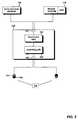
- Fig. 1schematically illustrates the components of a device 100 for detecting the braking of a vehicle.
- the device 100is mounted to a vehicle which is equipped with a driver assistance system 108.
- Device 100may be part of the driver assistance system, yet it may also be independent of said system.
- Device 100comprises an interface 101 towards the detector 107.
- Detector 107is mounted to the vehicle such that it detects light coming from a region in front of the vehicle. Detector 107 can thus detect light which is emitted by the rear lights of a vehicle travelling in front of the vehicle towards which device 100 is mounted. Detector 100 can for example detect light emitted by brake lights, hazard flashers, tail lights and the like. Several implementations of detector 107 are conceivable that are capable of performing this function.
- Detector 107can be a simple photo detector. It may then be provided with optical filters which transmit light of a particular colour corresponding to e.g. brake lights or hazard flashers. Detector 107 may also be a camera, such as a CCD or a CMOS camera, or a 3D camera, such as a photonic mixer device. In particular, it may be the optical detector or camera of the driver assistance system 108.
- Device 100further comprises processing unit 105, which can be implemented as one or more microprocessors, digital signal processors, application-specific integrated circuits or the like.
- Processing unit 105also comprises one or more types of memory.
- the processing unit 105controls the operation of device 100, e.g. in accordance with control instructions stored in such a memory.
- the functional units 103 and 104 illustrated in Fig. 1may also be implemented as software code portions that are being executed by processing unit 105.
- Processing unit 105is adapted to acquire over input/output unit 106 and interface 101 data from the detector 107.
- the acquired datacan be image data comprising a series of image frames, or it may be a simple photo detector signal indicating a detected light intensity.
- the acquired datacan at least temporarily be stored in the memory of processing unit 105.
- Analyzing unit 103processes the acquired data in order to detect an optical signal which is emitted by the rear light of the vehicle located in the region monitored by detector 107.
- the acquired datais analyzed to find an optical signal which encodes information on the braking procedure performed by the vehicle travelling ahead and which comprises and indication about the braking deceleration or braking strength of said vehicle.
- a plurality of possibilitiesexists for encoding such information into the light emitted by the rear lights of the preceding vehicle, and accordingly analyzing unit 103 analyzes the acquired data for a plurality of optical signals.
- An indication on braking strength that may be encoded in an optical signal emitted by the rear lightmay be that the vehicle is braking severly or performing an emergency braking.
- Optical signals for encoding such informationcomprise: flashing the brake lights at a particular frequency; activating the hazard flashers; increasing the intensity of the light emitted by the brake lights; increasing the area of the brake lights; illuminating two or more different areas of the rear lights at different intensities. Other optical signals are certainly conceivable.
- Increasing the area of the brake lighteffectively increases the brightness, which may for example be achieved by additionally illuminating the tail lights at a higher than normal intensity (e.g. corresponding to the intensity of the brake lights), providing a segmented brake light and lighting an additional segment, or the like.
- Analyzing unit 103can be adapted to detect one or any combination of the above optical signals.
- an optical signalcan be detected in different ways. If an intensity modulation of brake lights or activation of hazard flashers are used as optical signal, the data acquired from a simple photo detector or a camera can simply be analyzed by looking for the corresponding frequency in the acquired data. An increase in the area of brake lights can be detected by means of image analysis. An increase in intensity of light emitted by the brake lights may be detected by monitoring the intensity over a number of frames, so that a reference can be established. Otherwise, a reference on the size of the brake lights or their general intensity may be obtained from a database which stores such information for different types of vehicles. The vehicle type may be automatically identified by image analysis. When comparing the acquired data with a reference, attention may further be paid to the distance to the vehicle travelling ahead, which may be derived by means of detector 107 when implemented as a PMD, or by other means.
- Device 100further comprises evaluation unit 104 which derives the information provided in a detected optical signal, i.e. it decodes the optical signal. This is rather simple in the cases where the presence of the optical signal directly corresponds to a particular information. As an example, if any of the optical signals mentioned above is presented in the acquired data, evaluation unit 104 may determine that the preceding vehicle is performing an emergency braking. In other configurations, evaluation unit 104 may derive more detailed information. This is also illustrated further below with respect to Figs. 2-4 . As an example, evaluation unit 104 may derive from the frequency of a detected intensity modulation a rate of deceleration of the preceding vehicle.
- evaluation unit 104may derive from a relative difference in brightness between two areas of the rear lights of the preceding vehicle the information if the ABS of the preceding vehicle is activated or if a wheel of the preceding vehicle is locked. Accordingly, by making use of analyzing unit 103 and evaluation unit 104, device 100 has detailed information available on the braking procedure performed by the preceding vehicle.
- Optical signals for indicating an emergency brakingcan be provided such that they are human-perceivable, so that drivers of conventional vehicles can register the signal and can be alerted.
- Device 100is adapted to detect and evaluate such signals.
- Other optical signalssuch as the above-mentioned difference in brightness (or relative brightness) may not be human-perceivable, and device 100 is also adapted to detect these signals in the present embodiment. It should be clear that in other embodiments device 100 may be configured to detect only one or the other type of optical signal, or one or a combination of particular optical signals.
- Device 100further comprises an interface 102 towards driver assistance system 108 and driver warning system 109.
- device 100may generate a signal, such as a control signal, which is supplied to one or both systems.
- a signal supplied to driver warning system 109may prompt the system to provide an acoustic or visual warning to the driver, such as that the preceding vehicle is performing an emergency braking.
- Device 100may provide to driver assistance system 108 some or any of the derived information, depending on the configuration.
- Driver assistance system 108can then take corresponding measures. It may for example prepare brake system 110 for an upcoming emergency braking procedure, or it may initiate the operation of brake system 110 in order to slow down the vehicle. If the information derived by device 100 comprises the deceleration rate of the preceding vehicle, driver assistance system 108 may make use of such information by decelerating the vehicle correspondingly, or, if the deceleration is low, not engage in operation.
- the reaction time to an emergency braking of a preceding vehiclecan be significantly reduced.
- the vehiclecan directly and automatically react to such a situation.
- Such an automatic reactionis significantly faster compared to a human reaction, as the driver first has to recognize that the vehicle ahead is braking strongly and then has to take the appropriate measures.
- an acoustical or optical warning of the driverimproves the driver's reaction time.
- Device 100may be implemented in several different ways.
- Device 100may be a vehicle computing system with units 103 and 104 being implemented as software code portions running on the system. Interfaces 101 and 102 may for example be interfaces to a vehicle network, such as a controller area network or the like.
- device 100may be the processing unit of a driver assistance system. As such, based on the derived information, a corresponding control signal may be provided to a controlling function or controlling unit of the driver assistance system.
- Other implementationsare certainly conceivable.
- Fig. 2illustrates a method of detecting the braking of a vehicle according to an embodiment of the invention.
- Device 100 illustrated in Fig. 1may be configured so as to perform the method of Fig. 2 .
- a first step 201light emitted by the rear lights of a preceding vehicle is detected, e.g. by detector 107.
- the detectormonitors continuously an area in front of the vehicle, and as soon as the vehicle travelling ahead enters the monitored area, light emitted by its rear lights is detected.
- the rear lightscan comprise all types of light sources mounted to the preceding vehicle and emitting light in its rearward direction (e.g. brake lights, tail lights, hazard flashers, turn indicators, and the like).
- the brake lights of the preceding vehicleare activated, which is detected by detector 107.
- the detectionoccurs fast enough so that for example an intensity modulation or a change in intensity of the emitted light is detectable.
- step 202data is acquired from the detector. As mentioned above, this can occur by means of device 100 acquiring image frames, a simple detector signal or the like.
- the acquired datacan be in a digital data format, as this facilitates the later analysis.
- Detector 107may directly deliver digital data, or device 100 may comprise means for digitizing the data.
- the acquired datais analyzed for brightness of the brake lights, an intensity modulation of the brake lights and active hazard flashers in step 203. While in the present embodiment digital image frames are acquired, it should be clear that the method is similar applicable to other types of data with the necessary changes.
- the brightness of the brake lightscan be detected by analyzing the acquired image frames using for example a thresholding method, as active brake lights have in general a higher intensity than any of the other rearward facing lights of the preceding vehicle. Other methods such as edge detection or shape detection are certainly also conceivable for finding the position of the brake lights in the acquired image data.
- the perceived brightness of the brake lightscan then deduce from the pixel area of the brake lights in the image data and the pixel intensity values. It is even simpler to detect an intensity modulation of the brake lights.
- the position of the brake lightsmay again be identified using a thresholding method, whereas an intensity modulation can be identified by analyzing a time series of intensity values at the corresponding position, e.g. using a Fourier analysis, in order to derive a modulation frequency.
- the activation of hazard flashersmay be determined. A differentiation between brake lights and hazard flashers can occur by means of their respective colour (red or yellow, respectively).
- step 204it is determined whether an optical signal encoding information on a braking procedure is present in the acquired data. This may not be the case if the preceding vehicle is a conventional vehicle equipped with a standard brake light which is simply activated irrespective of the severeness of the braking procedure.
- an optical signalis present in the acquired data if in the above step an intensity modulation of the brake lights or an activation of the hazard flashers was detected, or if a particular brightness of the brake lights was determined. Changing the brightness of the brake lights for transmitting an optical signal can occur by increasing the intensity emitted by the brake lights or by increasing the light emitting area of the brake lights and thus also the overall intensity.
- the presence of such an optical signalcan be detected by analyzing a time series of images, from which a reference brightness for the brake light may be derived. By comparing the actual brightness value of the brake lights with this reference, an increase in brightness can be detected. Quite often the driver of the preceding vehicle will first engage the brakes with normal strength before performing an emergency braking, so that in general enough data for forming a reference will be available. Other methods of determining a reference, such as determining a brightness reference under consideration of the preceding vehicle's model and distance to the detector are certainly conceivable.
- the encoded informationcomprising a braking strength indication is derived in step 205.
- the optical signalis thus "decoded", i.e. its meaning is identified.
- optical signals that are human-perceivable and that indicate an severe or emergency brakingare detected in the acquired data in steps 203 and 204. Accordingly, if such an optical signal is present in the acquired data, it can be determined in step 205 that the preceding vehicle is performing a severe or an emergency braking, i.e. that it is braking strongly and thus has a high rate of deceleration. It should be clear that in other embodiments more complex information may be derived by a more detailed analysis of a detected optical signal.
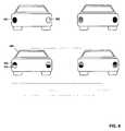
- the preceding vehiclemay relay further information to following vehicles by making use of relative light intensities emitted by the rear lights. Accordingly, the acquired data is analyzed for an optical signal in form of differences in brightness between different predetermined areas of the brake lights of the preceding vehicle in step 206. Such different areas of the rear lights of the preceding vehicle are schematically illustrated in Fig. 4 . For purposes of clarity, only the brake lights of the vehicle are indicated in the upper row of Fig. 4 . In the upper row, the relative brightness between a first area 151 being the left brake light and a second area 152 being the right brake light forms an optical signal and encodes information relayed by the preceding vehicle 180. In the lower row of Fig.
- First and second areas 151 and 152may for example be two different segments of a brake light or the brake light and a tail light or any other conceivable configuration. In the configuration of the lower row, each rear light may independently transmit information. In some embodiments, the differences in brightness between the first and second areas is not perceivable to the human eye while it is in others. Not being perceivable has the advantage that drivers of the following vehicle are not distracted.
- the detection of such a relative brightnesscan again occur by using thresholding (detecting pixels with an intensity above a threshold in the image data) in order to localize the positions of the brake lights and then comparing the brightness at the two positions in the acquired image data.
- step 207further information on the braking procedure performed by the preceding vehicles is derived in step 207.
- Such informationcan be of the binary type, e.g. whether the ABS is activated or a wheel of the preceding vehicle is locking during the braking procedure.
- the difference in the brightnessmay for example indicate the rate of deceleration of the preceding vehicle.
- the way the information is encoded in the relative brightnessmay be defined in a standard, and device 100 may comprise a look-up table for deriving the information from the detective relative brightness in accordance with such a standard. Manufacturer-specific implementations are certainly also conceivable, and the device 100 can be configured accordingly so that the corresponding information can be derived in step 207.
- the optical signal "left brake light brighter than right brake light”may encode the information "ABS active". Not only the existence or the amount of relative brightness may encode information, but also the position of the brighter or darker light emitting area.
- the optical signal "left brake light darker than right brake light”may thus encode "front wheels are locking”.
- the derived informationis used to generate a signal for a driver warning and/or driver assistance system.
- the signalmay comprise the derived information for interpretation by the corresponding system, or it may already comprise a control signal for initiating a particular function in the respective systems.
- the signal to the driver warning systemmay comprise a command to issue an acoustical warning to the driver
- the signal transmitted to the driver assistance systemmay comprise a command to initialize or to engage the braking system of the vehicle.
- the driver assistance systemBy transmitting the further information derived in step 207 to the driver assistance system, such as the deceleration rate of the preceding vehicle or whether ABS was activated, the response of the driver assistance system can be adjusted accordingly and the automatic reaction of the vehicle can be improved.
- the driver assistance systemcan trigger the braking with a corresponding deceleration or may initiate an emergency braking (e.g. if the preceding vehicle has activated its ABS).
- the methodmay be performed continuously while the vehicle is travelling.
- a human-perceivable optical signalis first recognized in order to identify an emergency braking performed by the preceding vehicle, and further information is then derived from an optical signal provided by the preceding vehicle in form of a relative brightness.
- the relative brightnessmay be detected and may indicate the occurrence of an emergency braking.
- steps 206 and 207may not be performed.
- the rate of deceleration of the preceding vehiclemay for example be derived from the frequency of the intensity modulation of brake lights or hazard flashers.
- Fig. 3illustrates a vehicle lighting control unit 300 that can be mounted to a vehicle and that controls the generation of an optical signal by making use of a relative brightness to transmit information as explained above with respect to Fig. 4 .
- Device 300thus interacts with device 100 by providing the optical signal that device 100 detects and evaluates.
- Device 300has a first interface 301 towards a brake system 110 of the vehicle in which it is installed, the brake system comprising an ABS, and towards an acceleration sensor 120.
- Brake system 110delivers information on how strongly the driver depresses the brake pedal (or how strongly the brakes are applied), whether the ABS is active and whether a wheel of the vehicle is locking.
- Acceleration sensor 120delivers information on the rate of deceleration of the vehicle.
- the lighting control unit 300further comprises an encoding unit 302 which encodes some or all of the information received on interface 301 into an optical signal in form of a relative brightness between at least two different areas of the vehicle's rear lights.
- the encodingmay for example be performed as explained above with respect to Fig. 4 .
- Controller 303then generates a corresponding control signal which is supplied to the rear lights 150 by means of interface 304.
- the rear lightscomprise brake lights having two segments forming a first area 151 and a second area 152 (for each brake light). Controller 303 then independently adjusts the intensity of light emitted from each of the segments.
- encoding unit 302may for example receive the information "ABS active” and may supply a corresponding light control signal to controller 303 with the commands "right brake light both segments 100% intensity” and "left brake light upper segment 80% intensity, lower segment 100% intensity”. Controller 303 then adjusts the brightness of the brake light segments accordingly, and thus transmits the information to following vehicles.
- optical signal making use of a relative brightnessmay be more complex as illustrated with respect to Fig. 4 , and that the controlling unit 300 may be adapted to control the generation of such a more complex signal.
- Each brake lightmay for example be divided in further segments, the light emission intensity of which may be independently controlled by controlling unit 300.
- Fig. 5is a schematic diagram illustrating the interaction between the device 100 of Fig. 1 and the controlling unit 300 of Fig. 3 .
- vehicle 170 detector 107is installed and monitors an area in the driving direction in which the preceding vehicle 180 is travelling.
- the preceding vehicle 180comprises the brake system 110 which is in communication with the lighting control unit 300. If the driver of vehicle 180 brakes strongly, controlling unit 300 receives the corresponding information and modulates the emission of light from rear lights 150 so as to provide any of the above-mentioned optical signals.
- This signalis detected by device 100 in the image data acquired from camera 107.
- Device 100is in this embodiment implemented within the driver assistance system 108. Device 100 performs the interpretation of the detected optical signal.
- the corresponding component of the driver assistance system 108supplies a control signal to the braking system 110 of vehicle 170 to activate the brakes. Accordingly, as soon as the optical signal is received, vehicle 170 can react without considerable delay.
Landscapes
- Engineering & Computer Science (AREA)
- Mechanical Engineering (AREA)
- Transportation (AREA)
- Physics & Mathematics (AREA)
- General Physics & Mathematics (AREA)
- Lighting Device Outwards From Vehicle And Optical Signal (AREA)
- Valves And Accessory Devices For Braking Systems (AREA)
Description
- The invention relates to a method of detecting the braking of a vehicle and to a device performing the method. The invention further relates to a vehicle lighting control unit which controls the emission of light from the rear lights of a vehicle.
- Conventional vehicles are equipped with brake lights which are illuminated in response to the driver actuating the brake pedal of the vehicle, resulting in a deceleration of the vehicle. The driver of the following vehicle is thus warned and enabled to react by reducing the speed. Modern vehicles often have an improved braking performance which can for example be achieved by making use of electronic systems such as the anti-lock braking system (ABS) or an electronic stability control system (ESC). Accordingly, a high deceleration can be achieved by such vehicles. This can be problematic for the driver in the following vehicle who only observes the illumination of the brake lights but has no indication about how strong the preceding vehicle is braking.
- Vehicle manufacturers are trying to overcome this problem by providing particular visible indications to the driver of the following vehicle by means of the rear lights. Examples of such indications are the flashing of the brake lights or the hazard flashers. Such an indication can be referred to as an emergency stop signal. Other implementations include increasing the brightness of the brake lights or increasing the light emitting area of the brake lights, e.g. by emitting light from an additional segment of the brake light or another light (which also increases the brightness perceived by the following driver). Yet up to date such systems were not able to show a significant improvement in the prevention of rear end collisions. This may be due to the fact that in both systems (regular brake lights and improved adaptive brake lights) the driver of the following vehicle has to recognize the braking and has to react accordingly.
GB 2 425 386 A DE 196 24 046 A1 discloses techniques for indicating a braking strength or deceleration of a vehicle. Illuminating center points, a light intensity, and an area of illumination of brake lights can be used to indicate the braking strength.- It is desirable to improve the warning of the driver so that rear end collisions can be avoided. In particular, the reaction time after which the following vehicle starts to decelerate should be improved. Also, the following vehicle would benefit from having more information available on the braking procedure performed by the preceding vehicle.
- Accordingly, there is a need to improve the detection of the braking of a vehicle and to mitigate at least some of the drawbacks mentioned above.
- This need is met by the features of the independent claims. The dependent claims describe embodiments of the invention.
- According to an aspect of the invention a method of detecting the braking of a vehicle is provided. The method is automatically performed by a device provided in a first vehicle, the device being in communication with a detector mounted to the first vehicle and monitoring an area in front of the first vehicle. The method comprises the steps of acquiring data from the detector which detects light emitted by the rear lights of the second vehicle if the second vehicle is travelling ahead of the first vehicle in the monitored area and of analyzing the acquired data in order to detect an optical signal which is emitted by the rear lights of the second vehicle and which encodes information on a braking procedure performed by the second vehicle comprising at least an indication on braking strength. Further, the detected optical signal is evaluated in order to derive the information on the braking procedure of the second vehicle encoded therein.
- With this method it is possible to automatically obtain an indication on the braking strength (or braking deceleration) of the vehicle travelling ahead. As the information is automatically obtained, reaction time may be reduced. As an example, the driver of the vehicle may be warned if the preceding vehicle is braking hardly, or a driver assistance system may be engaged on the basis of the derived information. As reaction times can be reduced, the braking of the vehicle can be initialized earlier and rear end collisions may be avoided.
- In an embodiment of the method, the analyzing of the acquired data is performed so as to detect a human perceivable optical signal encoding said information. Accordingly, the vehicles providing the optical signal may not need to be equipped with a particular encoder or signal generator, but conventional optical signals provided by such vehicles for drawing attention to e.g. a severe braking or emergency braking procedure can be automatically detected and evaluated by the present method.
- As an example, the acquired data may be analyzed so as to detect at least one of a brightness of the emitted light and an intensity modulation of the emitted light at a human perceivable frequency as the optical signal. Different brightnesses, which may be achieved by increasing the intensity of emitted light or the area of light emission, may indicate different braking strengths/ decelerations. An intensity modulation of a particular type of rear light or at a particular frequency may indicate an emergency braking. By analyzing the acquired data for brightness and intensity modulation, an optical signal indicating braking strength may thus be readily recognized. Such an analysis may further even detect brightness differences that are not human-perceivable.
- When evaluating a detected optical signal, at least one of the following information on the braking procedure performed by the second vehicle may be derived: An emergency braking performed by the second vehicle, a rate of deceleration of the second vehicle, an activation of an anti-lock braking system or the locking of a wheel. Obtaining such information has the advantage that a warning tailored to the actual traffic situation can be provided to the driver or driver assistance can be provided in accordance with the current traffic situation.
- In an embodiment the analyzing of the acquired data is performed such that at least one of the following optical signals emitted by the rear lights of the second vehicle is detectable: an intensity modulation of the brake light at a human perceivable frequency, preferably in the range between about 0.5 and about 10 Hz, even more preferably between about 1 and 5 Hz, e.g. at 4 Hz, an activation of a hazard flasher, an increase of a light emitting area of the brake lights, an increase of an intensity of light emitted by the brake lights or other lights (e.g. taillights), the presence of an intensity difference between different light emitting areas of the rear lights.
- Most of these optical signals can be human-perceivable. Yet some signals, such as a relative intensity between different light emitting areas or an intensity change of emitted light may not be human-perceivable. Further information can thus be derived by automatically analyzing the optical signal which is not visible to the human eye.
- As an example, the analyzing of the acquired data may comprise the determining of a brightness of at least a part of the second vehicle's rear lights from the acquired data and comparing the determined brightness with a threshold value, preferably under consideration of the current driving situation. An optical signal encoding a braking strength indication may then be detected if the determined brightness is higher than the threshold value. The analysis may consider current driving conditions which have an influence on the brightness perceived by the detector, such as distance between the vehicles, the type of the preceding vehicle, current weather conditions, and the like. The threshold value may be determined from a brightness reference under consideration of such conditions. A brightness reference may also be a previous brightness of said part of the second vehicle's rear lights. As an example, the brightness of a brake light may be detected several times, with a lower detected brightness forming a reference value for detecting a higher brightness.
- An increasing brightness of the preceding vehicle's rear lights, e.g. brake lights, can thus be easily identified.
- The analyzing of the acquired data also comprises the determining from the acquired data a brightness in at least a first light emitting area and a second light emitting area of the rear lights of the second vehicle. A relative brightness between the at least two areas and/or the locations of the areas having the relative brightness then is determined. The relative brightness and/or the determined locations then constitute the optical signal. As an example, the presence of a relative brightness between two areas may indicate a particular information, or the brightness difference may encode information, or the positioning of the brighter area and the darker area may encode information.
- The evaluation of the detected optical signal may comprise the determining of at least one of a rate of deceleration, the activation of an anti-lock braking system or the locking of a wheel of the second vehicle from the relative brightness. Such information may be encoded by different relative brightnesses or different locations of the brighter and darker light emitting areas.
- As an example, the first and second areas of the second vehicle's rear lights may be at least one of an upper part and a lower part of the brake light; a left part and a right part of the brake light; a left brake light and a right brake light; or a first part and a second part of an illumination pattern provided on a brake light. While a brightness difference between the left and right brake light may for example indicate the rate of deceleration, the location of the darker brake light (left or right) may indicate whether the anti-lock braking system (ABS) is engaged or not. Note that in some embodiments, the brightness differences may be visible to the human eye, while in others they may not be. The visibility of the brake lights may thus not be disturbed, while by means of the detector the encoded information can still be resolved.
- The analyzing of the acquired data may be performed so that an emergency stop signal emitted by the rear lights of the second vehicle is detectable as the optical signal. The emergency stop signal may for example be a signal as provided in ECE regulation 48.
- The method may further comprise generating a signal for a driver assistance system or a driver warning system of the first vehicle on the basis of the derived information. Such a generated signal can then be supplied to the corresponding system. Accordingly, driver assistance can be provided on the basis of the signal, e.g. by preparing the brake system of the vehicle or by activating the brake system of the vehicle. It may thus be ensured that a safe distance to the preceding vehicle is kept. Additionally or alternatively, a warning can be given out to the driver on the basis of the generated signal and thus on the derived information. As an example, an acoustic warning signal may be given out if an emergency braking of the preceding vehicle is detected.
- The method itself may be performed by a device being part of a driver assistance system, with the generated signal being supplied to the part of the system which is responsible for taking the corresponding action. The detector may be part of the driver assistance system, it may be a camera or a 3D camera, such as a photonic mixer device (PMD). In other embodiments a simple photo detector may be used, which can be provided with filters for filtering out the light emitted by the rear lights of the preceding vehicle.
- According to another aspect of the present invention, a device for detecting the braking of a vehicle is provided. The device is adapted to be mounted in a first vehicle. The device comprises an interface towards a detector mounted to the first vehicle and monitoring an area in front of the first vehicle. The device is adapted to acquire data from the detector over the interface, the detector detecting light emitted by the rear lights of a second vehicle if the second vehicle is travelling ahead of the first vehicle in the monitored area. The device further comprises an analyzing unit adapted to analyze the acquired data in order to detect an optical signal which is emitted by the rear lights of the second vehicle and which encodes information on a braking procedure performed by the second vehicle, the information comprising at least an indication on braking strength. The device is further provided with an evaluation unit which is adapted to evaluate the detected optical signal in order to derive the information on the braking procedure of the second vehicle encoded therein.
- With such a device advantages similar to the ones outlined above with respect to the inventive method may be achieved.
- According to an embodiment, the device further comprises an interface towards a driver assistance system or a driver warning system. The device may then be adapted to supply a signal corresponding to the derived information to the driver assistance system or the driver warning system, respectively. The device may as such also be part of a driver assistance system.
- The device may further be adapted so as to perform any of the above-mentioned methods.
- According to another aspect of the invention, a vehicle lighting control unit adapted to control the emission of light from the rear lights of a vehicle is provided. The control unit comprises an interface adapted to receive data on vehicle deceleration and/or a status of the vehicle's braking system, an encoding unit adapted to encode the information received on the interface into a light control signal and a controller adapted to independently adjust the intensity of light emitted from at least a first area and a second area of the rear lights in accordance with the light control signal. The encoding unit is configured such that information is encoded into a difference of intensity of light emitted by the at least two areas. The information may be encoded into the relative emitted light intensity or into the positioning of the at least two areas having said relative intensity.
- With such a lighting control unit, information on the braking procedure performed by the vehicle into which the unit is installed can be relayed to the following vehicle. The vehicle lighting control unit may thus interact with the device mentioned above if such a device is installed in the following vehicle. The device may automatically detect and decode the information transmitted by the vehicle lighting control unit. If the vehicle performs a severe braking, the reaction time of following vehicles can be reduced, and rear end collisions may thus be prevented.
- Besides the relative intensity, the position of the at least two areas may also encode information. With the same relative intensity, further information on the status of the vehicles braking system, such as whether the ABS is activated or a wheel is blocking, can be encoded and transmitted. Other information that may be encoded comprises the performing of a severe braking or an emergency stop (e.g. the driver slamming on the brake).
- In an embodiment the first and second areas of the vehicle's rear lights comprise at least one of an upper part and a lower part of the brake lights, a left part and a right part of the brake lights, a left brake light and a right brake light, or a pattern of areas provided on at least one brake light.
- The present invention further provides a computer program product that can be loaded into the internal memory of a computing device, the product comprising software code portions for performing any of the methods mentioned above.
- It should be understood that the features mentioned above and those yet to be explained below can be used not only in the respective combinations indicated, but also in other combinations or in isolation, without leaving the scope of the present invention.
- The foregoing and other features and advantages of the invention will become further apparent from the following detailed description of illustrative embodiments when read in conjunction with the accompanying drawings.
Fig. 1 is a schematic diagram illustrating the components of a device according to an embodiment of the invention.Fig. 2 is a flow chart illustrating the steps of a method according to an embodiment of the invention.Fig. 3 is a schematic diagram illustrating the components of a vehicle lighting control unit according to an embodiment of the invention.Fig. 4 is a schematic diagram illustrating different possibilities of encoding information in the relative intensity of light emitted by different light emitting areas of a vehicle's rear light.Fig. 5 is a schematic diagram illustrating the implementation of the device ofFig. 1 and the controlling unit ofFig. 3 in two vehicles and their interaction.Fig. 1 schematically illustrates the components of adevice 100 for detecting the braking of a vehicle. Thedevice 100 is mounted to a vehicle which is equipped with adriver assistance system 108.Device 100 may be part of the driver assistance system, yet it may also be independent of said system.Device 100 comprises aninterface 101 towards thedetector 107.Detector 107 is mounted to the vehicle such that it detects light coming from a region in front of the vehicle.Detector 107 can thus detect light which is emitted by the rear lights of a vehicle travelling in front of the vehicle towards whichdevice 100 is mounted.Detector 100 can for example detect light emitted by brake lights, hazard flashers, tail lights and the like. Several implementations ofdetector 107 are conceivable that are capable of performing this function.Detector 107 can be a simple photo detector. It may then be provided with optical filters which transmit light of a particular colour corresponding to e.g. brake lights or hazard flashers.Detector 107 may also be a camera, such as a CCD or a CMOS camera, or a 3D camera, such as a photonic mixer device. In particular, it may be the optical detector or camera of thedriver assistance system 108.Device 100 further comprises processingunit 105, which can be implemented as one or more microprocessors, digital signal processors, application-specific integrated circuits or the like.Processing unit 105 also comprises one or more types of memory. Theprocessing unit 105 controls the operation ofdevice 100, e.g. in accordance with control instructions stored in such a memory. Thefunctional units Fig. 1 may also be implemented as software code portions that are being executed by processingunit 105.Processing unit 105 is adapted to acquire over input/output unit 106 andinterface 101 data from thedetector 107. The acquired data can be image data comprising a series of image frames, or it may be a simple photo detector signal indicating a detected light intensity. The acquired data can at least temporarily be stored in the memory ofprocessing unit 105.- Analyzing
unit 103 processes the acquired data in order to detect an optical signal which is emitted by the rear light of the vehicle located in the region monitored bydetector 107. In particular, the acquired data is analyzed to find an optical signal which encodes information on the braking procedure performed by the vehicle travelling ahead and which comprises and indication about the braking deceleration or braking strength of said vehicle. A plurality of possibilities exists for encoding such information into the light emitted by the rear lights of the preceding vehicle, and accordingly analyzingunit 103 analyzes the acquired data for a plurality of optical signals. - An indication on braking strength that may be encoded in an optical signal emitted by the rear light may be that the vehicle is braking severly or performing an emergency braking. Optical signals for encoding such information comprise: flashing the brake lights at a particular frequency; activating the hazard flashers; increasing the intensity of the light emitted by the brake lights; increasing the area of the brake lights; illuminating two or more different areas of the rear lights at different intensities. Other optical signals are certainly conceivable. Increasing the area of the brake light effectively increases the brightness, which may for example be achieved by additionally illuminating the tail lights at a higher than normal intensity (e.g. corresponding to the intensity of the brake lights), providing a segmented brake light and lighting an additional segment, or the like. Analyzing
unit 103 can be adapted to detect one or any combination of the above optical signals. - Depending on the detector used, the presence of an optical signal can be detected in different ways. If an intensity modulation of brake lights or activation of hazard flashers are used as optical signal, the data acquired from a simple photo detector or a camera can simply be analyzed by looking for the corresponding frequency in the acquired data. An increase in the area of brake lights can be detected by means of image analysis. An increase in intensity of light emitted by the brake lights may be detected by monitoring the intensity over a number of frames, so that a reference can be established. Otherwise, a reference on the size of the brake lights or their general intensity may be obtained from a database which stores such information for different types of vehicles. The vehicle type may be automatically identified by image analysis. When comparing the acquired data with a reference, attention may further be paid to the distance to the vehicle travelling ahead, which may be derived by means of
detector 107 when implemented as a PMD, or by other means. - It is particularly advantageous if information is encoded by means of an intensity difference between different light emitting areas of the rear lights. In such a case image analyses can identify the position of the rear lights and the corresponding areas and without any reference determine the intensity difference. Detection of the optical signal in the acquired data is thus facilitated.
Device 100 further comprisesevaluation unit 104 which derives the information provided in a detected optical signal, i.e. it decodes the optical signal. This is rather simple in the cases where the presence of the optical signal directly corresponds to a particular information. As an example, if any of the optical signals mentioned above is presented in the acquired data,evaluation unit 104 may determine that the preceding vehicle is performing an emergency braking. In other configurations,evaluation unit 104 may derive more detailed information. This is also illustrated further below with respect toFigs. 2-4 . As an example,evaluation unit 104 may derive from the frequency of a detected intensity modulation a rate of deceleration of the preceding vehicle. Similarly, it may determine from the increase of intensity or from the difference between different light emitting areas a deceleration rate of the preceding vehicle. In a further example,evaluation unit 104 may derive from a relative difference in brightness between two areas of the rear lights of the preceding vehicle the information if the ABS of the preceding vehicle is activated or if a wheel of the preceding vehicle is locked. Accordingly, by making use of analyzingunit 103 andevaluation unit 104,device 100 has detailed information available on the braking procedure performed by the preceding vehicle.- Optical signals for indicating an emergency braking can be provided such that they are human-perceivable, so that drivers of conventional vehicles can register the signal and can be alerted.
Device 100 is adapted to detect and evaluate such signals. Other optical signals such as the above-mentioned difference in brightness (or relative brightness) may not be human-perceivable, anddevice 100 is also adapted to detect these signals in the present embodiment. It should be clear that inother embodiments device 100 may be configured to detect only one or the other type of optical signal, or one or a combination of particular optical signals. Device 100 further comprises aninterface 102 towardsdriver assistance system 108 anddriver warning system 109. In accordance with the information derived byevaluation unit 104,device 100 may generate a signal, such as a control signal, which is supplied to one or both systems. A signal supplied todriver warning system 109 may prompt the system to provide an acoustic or visual warning to the driver, such as that the preceding vehicle is performing an emergency braking.Device 100 may provide todriver assistance system 108 some or any of the derived information, depending on the configuration.Driver assistance system 108 can then take corresponding measures. It may for example preparebrake system 110 for an upcoming emergency braking procedure, or it may initiate the operation ofbrake system 110 in order to slow down the vehicle. If the information derived bydevice 100 comprises the deceleration rate of the preceding vehicle,driver assistance system 108 may make use of such information by decelerating the vehicle correspondingly, or, if the deceleration is low, not engage in operation.- By means of
device 100, the reaction time to an emergency braking of a preceding vehicle can be significantly reduced. By providing a corresponding signal todriver assistance system 108, the vehicle can directly and automatically react to such a situation. Such an automatic reaction is significantly faster compared to a human reaction, as the driver first has to recognize that the vehicle ahead is braking strongly and then has to take the appropriate measures. Similarly, an acoustical or optical warning of the driver improves the driver's reaction time. Device 100 may be implemented in several different ways.Device 100 may be a vehicle computing system withunits Interfaces device 100 may be the processing unit of a driver assistance system. As such, based on the derived information, a corresponding control signal may be provided to a controlling function or controlling unit of the driver assistance system. Other implementations are certainly conceivable.Fig. 2 illustrates a method of detecting the braking of a vehicle according to an embodiment of the invention.Device 100 illustrated inFig. 1 may be configured so as to perform the method ofFig. 2 . In afirst step 201, light emitted by the rear lights of a preceding vehicle is detected, e.g. bydetector 107. The detector monitors continuously an area in front of the vehicle, and as soon as the vehicle travelling ahead enters the monitored area, light emitted by its rear lights is detected. The rear lights can comprise all types of light sources mounted to the preceding vehicle and emitting light in its rearward direction (e.g. brake lights, tail lights, hazard flashers, turn indicators, and the like). If the driver of the preceding vehicle depresses the brake pedal, the brake lights of the preceding vehicle are activated, which is detected bydetector 107. The detection occurs fast enough so that for example an intensity modulation or a change in intensity of the emitted light is detectable.- In
step 202 data is acquired from the detector. As mentioned above, this can occur by means ofdevice 100 acquiring image frames, a simple detector signal or the like. The acquired data can be in a digital data format, as this facilitates the later analysis.Detector 107 may directly deliver digital data, ordevice 100 may comprise means for digitizing the data. - The acquired data is analyzed for brightness of the brake lights, an intensity modulation of the brake lights and active hazard flashers in
step 203. While in the present embodiment digital image frames are acquired, it should be clear that the method is similar applicable to other types of data with the necessary changes. The brightness of the brake lights can be detected by analyzing the acquired image frames using for example a thresholding method, as active brake lights have in general a higher intensity than any of the other rearward facing lights of the preceding vehicle. Other methods such as edge detection or shape detection are certainly also conceivable for finding the position of the brake lights in the acquired image data. The perceived brightness of the brake lights can then deduce from the pixel area of the brake lights in the image data and the pixel intensity values. It is even simpler to detect an intensity modulation of the brake lights. The position of the brake lights may again be identified using a thresholding method, whereas an intensity modulation can be identified by analyzing a time series of intensity values at the corresponding position, e.g. using a Fourier analysis, in order to derive a modulation frequency. Similarly, the activation of hazard flashers may be determined. A differentiation between brake lights and hazard flashers can occur by means of their respective colour (red or yellow, respectively). - In
step 204 it is determined whether an optical signal encoding information on a braking procedure is present in the acquired data. This may not be the case if the preceding vehicle is a conventional vehicle equipped with a standard brake light which is simply activated irrespective of the severeness of the braking procedure. In the present embodiment, an optical signal is present in the acquired data if in the above step an intensity modulation of the brake lights or an activation of the hazard flashers was detected, or if a particular brightness of the brake lights was determined. Changing the brightness of the brake lights for transmitting an optical signal can occur by increasing the intensity emitted by the brake lights or by increasing the light emitting area of the brake lights and thus also the overall intensity. The presence of such an optical signal can be detected by analyzing a time series of images, from which a reference brightness for the brake light may be derived. By comparing the actual brightness value of the brake lights with this reference, an increase in brightness can be detected. Quite often the driver of the preceding vehicle will first engage the brakes with normal strength before performing an emergency braking, so that in general enough data for forming a reference will be available. Other methods of determining a reference, such as determining a brightness reference under consideration of the preceding vehicle's model and distance to the detector are certainly conceivable. - If an optical signal is present in the acquired data, the encoded information comprising a braking strength indication is derived in
step 205. The optical signal is thus "decoded", i.e. its meaning is identified. In the present embodiment, optical signals that are human-perceivable and that indicate an severe or emergency braking are detected in the acquired data insteps step 205 that the preceding vehicle is performing a severe or an emergency braking, i.e. that it is braking strongly and thus has a high rate of deceleration. It should be clear that in other embodiments more complex information may be derived by a more detailed analysis of a detected optical signal. - Besides the human-perceivable emergency braking signal, the preceding vehicle may relay further information to following vehicles by making use of relative light intensities emitted by the rear lights. Accordingly, the acquired data is analyzed for an optical signal in form of differences in brightness between different predetermined areas of the brake lights of the preceding vehicle in
step 206. Such different areas of the rear lights of the preceding vehicle are schematically illustrated inFig. 4 . For purposes of clarity, only the brake lights of the vehicle are indicated in the upper row ofFig. 4 . In the upper row, the relative brightness between afirst area 151 being the left brake light and asecond area 152 being the right brake light forms an optical signal and encodes information relayed by the precedingvehicle 180. In the lower row ofFig. 4 , an optical signal in form of a relative brightness is provided between two parts of the same rear light. First andsecond areas - The detection of such a relative brightness can again occur by using thresholding (detecting pixels with an intensity above a threshold in the image data) in order to localize the positions of the brake lights and then comparing the brightness at the two positions in the acquired image data.
- From the detected relative brightness, further information on the braking procedure performed by the preceding vehicles is derived in
step 207. Such information can be of the binary type, e.g. whether the ABS is activated or a wheel of the preceding vehicle is locking during the braking procedure. Yet it may also be more complex, the difference in the brightness may for example indicate the rate of deceleration of the preceding vehicle. The way the information is encoded in the relative brightness may be defined in a standard, anddevice 100 may comprise a look-up table for deriving the information from the detective relative brightness in accordance with such a standard. Manufacturer-specific implementations are certainly also conceivable, and thedevice 100 can be configured accordingly so that the corresponding information can be derived instep 207. - In the example of
Fig. 4 the optical signal "left brake light brighter than right brake light" may encode the information "ABS active". Not only the existence or the amount of relative brightness may encode information, but also the position of the brighter or darker light emitting area. The optical signal "left brake light darker than right brake light" may thus encode "front wheels are locking". A skilled person will appreciate that there are various ways of encoding information relating to the braking procedure of the precedingvehicle 180 into a relative brightness of the rear lights, and that all these variations lie within the scope of the present invention. - In
step 208, the derived information is used to generate a signal for a driver warning and/or driver assistance system. The signal may comprise the derived information for interpretation by the corresponding system, or it may already comprise a control signal for initiating a particular function in the respective systems. For a detected emergency braking procedure performed by the preceding vehicle, the signal to the driver warning system may comprise a command to issue an acoustical warning to the driver, and the signal transmitted to the driver assistance system may comprise a command to initialize or to engage the braking system of the vehicle. By means of the acoustic warning, the reaction time of the driver is reduced, while by automatically engaging the brakes, the delay until the vehicle starts to decelerate is significantly reduced. By transmitting the further information derived instep 207 to the driver assistance system, such as the deceleration rate of the preceding vehicle or whether ABS was activated, the response of the driver assistance system can be adjusted accordingly and the automatic reaction of the vehicle can be improved. The driver assistance system can trigger the braking with a corresponding deceleration or may initiate an emergency braking (e.g. if the preceding vehicle has activated its ABS). - The method may be performed continuously while the vehicle is travelling. With the method of the present embodiment, a human-perceivable optical signal is first recognized in order to identify an emergency braking performed by the preceding vehicle, and further information is then derived from an optical signal provided by the preceding vehicle in form of a relative brightness. It should be clear that in other embodiments only the relative brightness may be detected and may indicate the occurrence of an emergency braking. In other embodiments,
steps steps Fig. 3 illustrates a vehiclelighting control unit 300 that can be mounted to a vehicle and that controls the generation of an optical signal by making use of a relative brightness to transmit information as explained above with respect toFig. 4 .Device 300 thus interacts withdevice 100 by providing the optical signal thatdevice 100 detects and evaluates.Device 300 has afirst interface 301 towards abrake system 110 of the vehicle in which it is installed, the brake system comprising an ABS, and towards anacceleration sensor 120.Brake system 110 delivers information on how strongly the driver depresses the brake pedal (or how strongly the brakes are applied), whether the ABS is active and whether a wheel of the vehicle is locking.Acceleration sensor 120 delivers information on the rate of deceleration of the vehicle.- The
lighting control unit 300 further comprises anencoding unit 302 which encodes some or all of the information received oninterface 301 into an optical signal in form of a relative brightness between at least two different areas of the vehicle's rear lights. The encoding may for example be performed as explained above with respect toFig. 4 . Controller 303 then generates a corresponding control signal which is supplied to therear lights 150 by means ofinterface 304. In the particular embodiment ofFig. 3 , the rear lights comprise brake lights having two segments forming afirst area 151 and a second area 152 (for each brake light).Controller 303 then independently adjusts the intensity of light emitted from each of the segments.- In operation, encoding
unit 302 may for example receive the information "ABS active" and may supply a corresponding light control signal tocontroller 303 with the commands "right brake light bothsegments 100% intensity" and "left brake light upper segment 80% intensity,lower segment 100% intensity".Controller 303 then adjusts the brightness of the brake light segments accordingly, and thus transmits the information to following vehicles. - It should be clear that the optical signal making use of a relative brightness may be more complex as illustrated with respect to
Fig. 4 , and that the controllingunit 300 may be adapted to control the generation of such a more complex signal. Each brake light may for example be divided in further segments, the light emission intensity of which may be independently controlled by controllingunit 300. Fig. 5 is a schematic diagram illustrating the interaction between thedevice 100 ofFig. 1 and the controllingunit 300 ofFig. 3 . In the followingvehicle 170detector 107 is installed and monitors an area in the driving direction in which the precedingvehicle 180 is travelling. The precedingvehicle 180 comprises thebrake system 110 which is in communication with thelighting control unit 300. If the driver ofvehicle 180 brakes strongly, controllingunit 300 receives the corresponding information and modulates the emission of light fromrear lights 150 so as to provide any of the above-mentioned optical signals. This signal is detected bydevice 100 in the image data acquired fromcamera 107.Device 100 is in this embodiment implemented within thedriver assistance system 108.Device 100 performs the interpretation of the detected optical signal. If the derived information indicates that an emergency braking is necessary, the corresponding component of thedriver assistance system 108 supplies a control signal to thebraking system 110 ofvehicle 170 to activate the brakes. Accordingly, as soon as the optical signal is received,vehicle 170 can react without considerable delay.- In particular at high velocities, a small fraction of a second already corresponds to a travelled distance of several meters. The improved reaction time thus increases the distance between
vehicles
Claims (16)
- A method of detecting the braking of a vehicle, the method being automatically performed by a device (100) provided in a first vehicle (170), the device being in communication with a detector (107) mounted to the first vehicle (170) and monitoring an area in front of the first vehicle, the method comprising the steps of- acquiring data from the detector (107) which detects light emitted by the rear lights of a second vehicle (180) if the second vehicle is travelling ahead of the first vehicle (170) in the monitored area;- analyzing the acquired data in order to detect an optical signal which is emitted by the rear lights (150) of the second vehicle (180) and which encodes information on a braking procedure performed by the second vehicle (180) comprising at least an indication on braking strength;- evaluating the detected optical signal in order to derive the information on the braking procedure of the second vehicle (180) encoded therein,wherein the analyzing of the acquired data comprises- determining from said acquired data a brightness in at least a first light emitting area (151) and a second light emitting area (152) of the rear lights (150) of the second vehicle (180),- determining a relative brightness between the at least two areas (151, 152) and/or determining the locations of the areas (151, 152) having said relative brightness, said relative brightness and/or locations being detected as said optical signal.
- The method according to claim 1, wherein the analyzing of the acquired data is performed so as to detect a human perceivable optical signal encoding said information.
- The method according to claim 1 or 2, wherein the analyzing of the acquired data is performed so as to detect at least one of a brightness of the emitted light and an intensity modulation of the emitted light at a human perceivable frequency as said optical signal.
- The method according to any of the preceding claims, wherein the evaluation of the detected optical signal is performed such that at least one of the following information on the braking procedure performed by the second vehicle (180) can be derived:- an emergency braking performed by the second vehicle,- a rate of deceleration of the second vehicle,- an activation of an anti-lock braking system,- a locking of a wheel.
- The method according to any of the preceding claims, wherein the analyzing of the acquired data is performed such that at least one of the following optical signals emitted by the rear lights of the second vehicle (180) is detectable:- a intensity modulation of a brake light at a human perceivable frequency, preferably in the range between about 0.5 and about 10 Hz;- an activation of a hazard flasher;- an increase of a light emitting area of the brake lights;- an increase of an intensity of light emitted by the brake lights;- the presence of an intensity difference between different light emitting areas of the rear lights.
- The method according to any of the preceding claims, wherein the analyzing of the acquired data comprises
determining a brightness of at least a part of said second vehicle's rear lights (150) from the acquired data and
comparing the determined brightness with a threshold value, preferably under consideration of the current driving situation, wherein an optical signal encoding a braking strength indication is detected if the determined brightness is higher than the threshold value. - The method according to any of the preceding claims, wherein the evaluation of the detected optical signal comprises determining at least one of a rate of deceleration, the activation of an anti-lock braking system or the locking of a wheel of the second vehicle (180) from said relative brightness.
- The method according to any of the preceding claims, wherein said first and second areas (151,152) of the second vehicle's rear lights (150) are at least one of- an upper part and a lower part of a brake light;- a left part and a right part of a brake light;- a left brake light and a right brake light;- a firs part and a second part of illumination pattern provided on a brake light.
- The method according to any of the preceding claims, wherein the analyzing of the acquired data is performed so that an Emergency Stop Signal emitted by the rear lights (150) of the second vehicle (180) is detectable as said optical signal.
- The method according to any of the preceding claims, further comprising the step of supplying a signal corresponding to the derived information to a driver assistance system (108) or a driver warning system (109) of said first vehicle (170).
- A device for detecting the braking of a vehicle, the device (100) being adapted to be mounted in a first vehicle (170) and comprising:- an interface (101) towards a detector (107) mounted to the first vehicle (170) and monitoring an area in front of the first vehicle, the device (100) being adapted to acquire data from the detector (107) over the interface (101), the detector (107) detecting light emitted by the rear lights (150) of a second vehicle (180) if the second vehicle (180) is travelling ahead of the first vehicle (170) in the monitored area;- an analyzing unit (103) adapted to analyze the acquired data in order to detect an optical signal which is emitted by the rear lights (150) of the second vehicle (180) and which encodes information on a braking procedure performed by the second vehicle (180) comprising at least an indication on braking strength; wherein the analyzing of the acquired data comprises- determining from said acquired data a brightness in at least a first light emitting area (151) and a second light emitting area (152) of the rear lights (150) of the second vehicle (180),- determining a relative brightness between the at least two areas (151, 152) and/or determining the locations of the areas (151, 152) having said relative brightness, said relative brightness and/or locations being detected as said optical signal;- and- an evaluation unit (104)-adapted to evaluate the detected optical signal in order to derive the information on the braking procedure of the second vehicle (108) encoded therein.
- The device according to claim 11, wherein the device (100) further comprises an interface (102) towards a driver assistance system (108) or a driver warning system (109), the device (100) being adapted to supply a signal corresponding to the derived information to said driver assistance system (108) or said driver warning system (109), respectively.
- The device according to claim 11 or 12, wherein the device is adapted so as to perform the method according to any one of claims 2-10.
- A vehicle lighting control unit (300) adapted to control the emission of light from the rear lights (150) of a vehicle (180), the vehicle lighting control unit (300) comprising:- an interface (301) adapted to receive data on vehicle deceleration and/or a status of the vehicle's braking system (110),- an encoding unit (302) adapted to encode the information received on said interface (301) into a light control signal,- a controller (303) adapted to independently adjust the intensity of light emitted from at least a first light emitting area (151) and a second light emitting area (152) of said rear lights (150) in accordance with the light control signal,wherein the encoding unit (302) is configured such that the information is encoded into a difference of intensity of light emitted by the at least two light-emitting areas (151,152).
- The vehicle lighting control unit according to claim 14, wherein said first and second light emitting areas (151, 152) of the vehicle's rear lights (150) comprise at least one of- an upper part and a lower part of a brake light;- a left part and a right part of a brake light;- a left brake light and a right brake light,- a pattern of areas provided on at least one brake light.
- A computer program product that can be loaded into the internal memory of a computing device, said product comprising software code portions for performing the method of one of claims 1-10 when the product is executed.
Priority Applications (5)
| Application Number | Priority Date | Filing Date | Title |
|---|---|---|---|
| EP20100008769EP2423063B1 (en) | 2010-08-23 | 2010-08-23 | Method of detecting the braking of a vehicle |
| JP2011172093AJP5996852B2 (en) | 2010-08-23 | 2011-08-05 | How to detect vehicle braking |
| US13/213,918US8957772B2 (en) | 2010-08-23 | 2011-08-19 | System for vehicle braking detection |
| CN201110242102.0ACN102381298B (en) | 2010-08-23 | 2011-08-23 | The method of detection vehicle braking |
| US14/592,812US9387798B2 (en) | 2010-08-23 | 2015-01-08 | System for vehicle braking detection |
Applications Claiming Priority (1)
| Application Number | Priority Date | Filing Date | Title |
|---|---|---|---|
| EP20100008769EP2423063B1 (en) | 2010-08-23 | 2010-08-23 | Method of detecting the braking of a vehicle |
Publications (2)
| Publication Number | Publication Date |
|---|---|
| EP2423063A1 EP2423063A1 (en) | 2012-02-29 |
| EP2423063B1true EP2423063B1 (en) | 2013-03-06 |
Family
ID=43640620
Family Applications (1)
| Application Number | Title | Priority Date | Filing Date |
|---|---|---|---|
| EP20100008769ActiveEP2423063B1 (en) | 2010-08-23 | 2010-08-23 | Method of detecting the braking of a vehicle |
Country Status (4)
| Country | Link |
|---|---|
| US (2) | US8957772B2 (en) |
| EP (1) | EP2423063B1 (en) |
| JP (1) | JP5996852B2 (en) |
| CN (1) | CN102381298B (en) |
Families Citing this family (91)
| Publication number | Priority date | Publication date | Assignee | Title |
|---|---|---|---|---|
| US7221287B2 (en) | 2002-03-05 | 2007-05-22 | Triangle Software Llc | Three-dimensional traffic report |
| WO2005013063A2 (en) | 2003-07-25 | 2005-02-10 | Landsonar, Inc. | System and method for determining recommended departure time |
| US8619072B2 (en) | 2009-03-04 | 2013-12-31 | Triangle Software Llc | Controlling a three-dimensional virtual broadcast presentation |
| US20120083983A1 (en)* | 2009-06-19 | 2012-04-05 | Bosch Corporation | Vehicular braking control device |
| WO2012145819A1 (en) | 2011-04-25 | 2012-11-01 | Magna International Inc. | Image processing method for detecting objects using relative motion |
| US8725396B2 (en) | 2011-05-18 | 2014-05-13 | Pelmorex Canada Inc. | System for providing traffic data and driving efficiency data |
| US20140218535A1 (en) | 2011-09-21 | 2014-08-07 | Magna Electronics Inc. | Vehicle vision system using image data transmission and power supply via a coaxial cable |
| US9681062B2 (en) | 2011-09-26 | 2017-06-13 | Magna Electronics Inc. | Vehicle camera image quality improvement in poor visibility conditions by contrast amplification |
| US10099614B2 (en) | 2011-11-28 | 2018-10-16 | Magna Electronics Inc. | Vision system for vehicle |
| WO2013113029A1 (en) | 2012-01-27 | 2013-08-01 | Triangle Software, Llc | Estimating time travel distributions on signalized arterials |
| US10609335B2 (en) | 2012-03-23 | 2020-03-31 | Magna Electronics Inc. | Vehicle vision system with accelerated object confirmation |
| US9751465B2 (en) | 2012-04-16 | 2017-09-05 | Magna Electronics Inc. | Vehicle vision system with reduced image color data processing by use of dithering |
| US10089537B2 (en) | 2012-05-18 | 2018-10-02 | Magna Electronics Inc. | Vehicle vision system with front and rear camera integration |
| US9558667B2 (en)* | 2012-07-09 | 2017-01-31 | Elwha Llc | Systems and methods for cooperative collision detection |
| US9165469B2 (en) | 2012-07-09 | 2015-10-20 | Elwha Llc | Systems and methods for coordinating sensor operation for collision detection |
| US9000903B2 (en) | 2012-07-09 | 2015-04-07 | Elwha Llc | Systems and methods for vehicle monitoring |
| US10223909B2 (en) | 2012-10-18 | 2019-03-05 | Uber Technologies, Inc. | Estimating time travel distributions on signalized arterials |
| JP6031956B2 (en)* | 2012-11-15 | 2016-11-24 | 株式会社デンソー | Communication device |
| US9743002B2 (en) | 2012-11-19 | 2017-08-22 | Magna Electronics Inc. | Vehicle vision system with enhanced display functions |
| US10025994B2 (en) | 2012-12-04 | 2018-07-17 | Magna Electronics Inc. | Vehicle vision system utilizing corner detection |
| US9481301B2 (en) | 2012-12-05 | 2016-11-01 | Magna Electronics Inc. | Vehicle vision system utilizing camera synchronization |
| US20140168415A1 (en) | 2012-12-07 | 2014-06-19 | Magna Electronics Inc. | Vehicle vision system with micro lens array |
| US20140218529A1 (en) | 2013-02-04 | 2014-08-07 | Magna Electronics Inc. | Vehicle data recording system |
| US10027930B2 (en) | 2013-03-29 | 2018-07-17 | Magna Electronics Inc. | Spectral filtering for vehicular driver assistance systems |
| US9327693B2 (en) | 2013-04-10 | 2016-05-03 | Magna Electronics Inc. | Rear collision avoidance system for vehicle |
| US9454905B2 (en)* | 2013-04-29 | 2016-09-27 | Global Foundries Inc. | Safe distance determination |
| US10232797B2 (en) | 2013-04-29 | 2019-03-19 | Magna Electronics Inc. | Rear vision system for vehicle with dual purpose signal lines |
| CN104149729B (en)* | 2013-05-13 | 2017-07-21 | 上海汽车集团股份有限公司 | The method and system of identification traveling vehicle periphery barrier |
| CN103264656A (en)* | 2013-05-24 | 2013-08-28 | 北京汽车股份有限公司 | Braking state attention device and vehicle |
| US9283887B1 (en)* | 2013-06-07 | 2016-03-15 | Emergency Technology, Inc. | Emergency vehicle signal control system |
| US10567705B2 (en) | 2013-06-10 | 2020-02-18 | Magna Electronics Inc. | Coaxial cable with bidirectional data transmission |
| US9260095B2 (en) | 2013-06-19 | 2016-02-16 | Magna Electronics Inc. | Vehicle vision system with collision mitigation |
| US9776632B2 (en) | 2013-07-31 | 2017-10-03 | Elwha Llc | Systems and methods for adaptive vehicle sensing systems |
| US9230442B2 (en) | 2013-07-31 | 2016-01-05 | Elwha Llc | Systems and methods for adaptive vehicle sensing systems |
| US9269268B2 (en) | 2013-07-31 | 2016-02-23 | Elwha Llc | Systems and methods for adaptive vehicle sensing systems |
| US9619716B2 (en) | 2013-08-12 | 2017-04-11 | Magna Electronics Inc. | Vehicle vision system with image classification |
| US10326969B2 (en) | 2013-08-12 | 2019-06-18 | Magna Electronics Inc. | Vehicle vision system with reduction of temporal noise in images |
| DE102014208659A1 (en)* | 2013-09-06 | 2015-03-12 | Robert Bosch Gmbh | System for transmitting information in the determination of wrong-way driving of a motor vehicle, associated transmitting and receiving devices and corresponding transmitting and receiving methods |
| US9305460B1 (en)* | 2013-10-28 | 2016-04-05 | John Justine Aza | Roadway warning light detector and method of warning a motorist |
| US9988047B2 (en) | 2013-12-12 | 2018-06-05 | Magna Electronics Inc. | Vehicle control system with traffic driving control |
| US11244171B2 (en)* | 2014-01-22 | 2022-02-08 | Conduent Business Services Llc | Video-based system for automated detection of double parking violations |
| US9623878B2 (en) | 2014-04-02 | 2017-04-18 | Magna Electronics Inc. | Personalized driver assistance system for vehicle |
| US9766628B1 (en)* | 2014-04-04 | 2017-09-19 | Waymo Llc | Vision-based object detection using a polar grid |
| JP6281483B2 (en)* | 2014-04-17 | 2018-02-21 | 株式会社デンソー | Failure detection system, information processing apparatus, and vehicle mounting apparatus |
| GB2526797A (en)* | 2014-06-02 | 2015-12-09 | Ibm | Additional assistance lights |
| EP2985197A1 (en)* | 2014-08-15 | 2016-02-17 | Nederlandse Organisatie voor toegepast- natuurwetenschappelijk onderzoek TNO | Brake assistance method, equipment, and use. |
| US9925980B2 (en) | 2014-09-17 | 2018-03-27 | Magna Electronics Inc. | Vehicle collision avoidance system with enhanced pedestrian avoidance |
| DE102014014938A1 (en)* | 2014-10-07 | 2016-04-07 | Audi Ag | Method for operating a motor vehicle with an optical sensor and motor vehicle |
| JP6092272B2 (en)* | 2015-01-28 | 2017-03-08 | 本田技研工業株式会社 | Vehicle travel control device |
| US10286855B2 (en) | 2015-03-23 | 2019-05-14 | Magna Electronics Inc. | Vehicle vision system with video compression |
| US9710720B2 (en)* | 2015-04-29 | 2017-07-18 | General Electric Company | System and method of image analysis for automated asset identification |
| US10819943B2 (en) | 2015-05-07 | 2020-10-27 | Magna Electronics Inc. | Vehicle vision system with incident recording function |
| DE102015213078A1 (en)* | 2015-07-13 | 2017-01-19 | Conti Temic Microelectronic Gmbh | Brake light detection for vehicles in front to adapt an activation of active safety mechanisms |
| US10144419B2 (en) | 2015-11-23 | 2018-12-04 | Magna Electronics Inc. | Vehicle dynamic control system for emergency handling |
| EP3176725B1 (en)* | 2015-12-03 | 2019-04-10 | Continental Automotive GmbH | Method and device for detecting a braking application of a vehicle |
| EP3179748A1 (en)* | 2015-12-08 | 2017-06-14 | Harman Becker Automotive Systems GmbH | System and method for car-to-car communication |
| US11285878B2 (en) | 2015-12-17 | 2022-03-29 | Magna Electronics Inc. | Vehicle vision system with camera line power filter |
| DE102016216745A1 (en)* | 2015-12-18 | 2017-06-22 | Ford Global Technologies, Llc | Method for operating a motor vehicle |
| CN105489036A (en)* | 2015-12-28 | 2016-04-13 | 南宁学院 | FSC racing car brake prompting system |
| US10424203B2 (en)* | 2016-01-29 | 2019-09-24 | Toyota Motor Engineering & Manufacturing North America, Inc. | System and method for driving hazard estimation using vehicle-to-vehicle communication |
| TWI618647B (en) | 2016-02-02 | 2018-03-21 | 財團法人資訊工業策進會 | System and method of detection, tracking and identification of evolutionary adaptation of vehicle lamp |
| JP6642886B2 (en)* | 2016-03-24 | 2020-02-12 | 株式会社Subaru | Vehicle driving support device |
| CN106056915B (en)* | 2016-06-17 | 2019-07-23 | 京东方科技集团股份有限公司 | Vehicle identity information recognition methods and system, identification device and acquisition device |
| WO2018024320A1 (en)* | 2016-08-02 | 2018-02-08 | Bayerische Motoren Werke Aktiengesellschaft | A method for learning an illumination-pattern of a monitored automobile and a respective automobile |
| IT201600082299A1 (en)* | 2016-08-04 | 2018-02-04 | Piaggio & C Spa | Motorcycle with obstacle and / or collision risk sensor |
| CN106627346A (en)* | 2016-12-12 | 2017-05-10 | 曹曦 | Automobile tail light and flashing method thereof |
| US10607094B2 (en) | 2017-02-06 | 2020-03-31 | Magna Electronics Inc. | Vehicle vision system with traffic sign recognition |
| US10442429B2 (en)* | 2017-03-30 | 2019-10-15 | Ford Global Technologies, Llc | Wrong-way vehicle detection |
| CN107650778A (en)* | 2017-09-04 | 2018-02-02 | 北京小米移动软件有限公司 | Light for vehicle control method and device and storage medium |
| US10733465B2 (en)* | 2017-09-20 | 2020-08-04 | Tusimple, Inc. | System and method for vehicle taillight state recognition |
| KR101988563B1 (en)* | 2017-10-26 | 2019-09-30 | 주식회사 만도 | Vehicle collision protection control device, vehicle collision protection control system, and vehicle collision protection control method |
| US10870556B2 (en)* | 2017-12-12 | 2020-12-22 | Otis Elevator Company | Method and system for detecting elevator car operating panel condition |
| DE102017129946A1 (en)* | 2017-12-14 | 2019-06-19 | HELLA GmbH & Co. KGaA | Method for detecting incorrect settings of the cut-off of a headlight |
| US10732640B2 (en)* | 2018-04-13 | 2020-08-04 | Blackberry Limited | System and method for preforming differential analysis of vehicles |
| US10358082B1 (en) | 2018-07-26 | 2019-07-23 | Kinney ASWD Holding Company, LLC | Advanced warning lighting systems and methods |
| ES2948392T3 (en)* | 2018-09-18 | 2023-09-11 | Faiveley Transport Italia Spa | Position recognition system along a train of a mechatronic braking control device associated with a railway vehicle |
| US10887023B1 (en) | 2018-10-10 | 2021-01-05 | Wayfarer, Inc. | Variable bandwidth free-space optical communication system for autonomous or semi-autonomous passenger vehicles |
| US11014570B2 (en)* | 2018-12-10 | 2021-05-25 | Continental Automotive Systems, Inc. | Front car rear tire anomalies detection system and related methods |
| CN109795405A (en)* | 2019-03-07 | 2019-05-24 | 董博 | A kind of driving status warning system based on vehicle airbag control unit |
| US11148670B2 (en)* | 2019-03-15 | 2021-10-19 | Honda Motor Co., Ltd. | System and method for identifying a type of vehicle occupant based on locations of a portable device |
| CN110027466A (en)* | 2019-03-20 | 2019-07-19 | 丽清汽车科技(上海)有限公司 | A kind of intelligence detecting of automobile and taillight control system and its control method |
| CN112085962B (en)* | 2019-06-14 | 2022-10-25 | 富士通株式会社 | Image-based parking detection method and device and electronic equipment |
| US11597361B2 (en)* | 2019-09-25 | 2023-03-07 | Zf Friedrichshafen Ag | Vehicle assist system |
| DE102020100225A1 (en)* | 2020-01-08 | 2021-07-08 | Knorr-Bremse Systeme für Nutzfahrzeuge GmbH | System and method for vehicle component behavior assessment |
| EP4168281B1 (en)* | 2020-06-19 | 2025-05-21 | Glydways, Inc. | Braking and signaling schemes for autonomous vehicle system |
| DE102020125683A1 (en)* | 2020-10-01 | 2022-04-07 | Audi Aktiengesellschaft | Motor vehicle with exterior lights and a control device |
| US11968639B2 (en) | 2020-11-11 | 2024-04-23 | Magna Electronics Inc. | Vehicular control system with synchronized communication between control units |
| CN114643960A (en)* | 2020-12-18 | 2022-06-21 | 宝能汽车集团有限公司 | Vehicle, control method thereof, and storage medium |
| US20220281451A1 (en)* | 2021-03-04 | 2022-09-08 | GM Global Technology Operations LLC | Target vehicle state identification for automated driving adaptation in vehicles control |
| CN113401118B (en)* | 2021-04-29 | 2022-09-27 | 长安大学 | Driving auxiliary system and method for predicting front vehicle braking |
| US20230099674A1 (en)* | 2021-09-29 | 2023-03-30 | Subaru Corporation | Vehicle backup warning systems |
Family Cites Families (33)
| Publication number | Priority date | Publication date | Assignee | Title |
|---|---|---|---|---|
| DE3516118A1 (en)* | 1985-05-04 | 1986-11-06 | Manfred 6110 Dieburg Rothkegel | Device for indicating braking in motor vehicles |
| US5463370A (en)* | 1988-07-18 | 1995-10-31 | Tamapack Co., Ltd. | Display device for a vehicle |
| US5760708A (en)* | 1989-11-21 | 1998-06-02 | Seith; Nancy | Signaling means |
| DE4305186C2 (en)* | 1993-02-19 | 1996-02-01 | Gerhaher Max | Procedure for reducing the risk of rear-end collisions in road traffic using a deceleration warning and deceleration warning system |
| US5610578A (en)* | 1996-05-13 | 1997-03-11 | Gilmore; Florent J. | Vehicular variable brake light intensity system |
| DE19624046A1 (en)* | 1996-06-17 | 1997-12-18 | Bayerische Motoren Werke Ag | Method and device for indicating the braking strength or deceleration in a vehicle |
| US5786752A (en)* | 1996-07-12 | 1998-07-28 | Bucalo; Louis R. | Emergency signal system for vehicles |
| JPH1153689A (en)* | 1997-08-05 | 1999-02-26 | Toyota Motor Corp | Vehicle-to-vehicle communication device |
| US6150933A (en)* | 1999-04-07 | 2000-11-21 | Matsumoto; Kiyoto | Vehicle brake light system |
| US6333688B1 (en)* | 2000-03-17 | 2001-12-25 | Tyrone A. Brown | Tail light enhancement system |
| US6335682B1 (en)* | 2000-07-05 | 2002-01-01 | International Business Machines Corporation | Method and system for enhanced system automotive brake light control |
| US20030211842A1 (en) | 2002-02-19 | 2003-11-13 | James Kempf | Securing binding update using address based keys |
| EP1521980B1 (en) | 2002-07-05 | 2015-06-17 | Continental Teves AG & Co. oHG | System for preventing a rear-end collision |
| DE10328755A1 (en)* | 2002-07-05 | 2004-07-15 | Continental Teves Ag & Co. Ohg | System to avoid rear-end collisions |
| KR100512954B1 (en) | 2003-03-12 | 2005-09-07 | 삼성전자주식회사 | RR method for secure communication |
| US7332877B2 (en)* | 2003-11-24 | 2008-02-19 | Glowleds, Inc. | Light controller |
| US7077549B1 (en)* | 2004-02-04 | 2006-07-18 | Corliss Joseph J | Vehicle warning light system |
| US20050253700A1 (en)* | 2004-05-14 | 2005-11-17 | Keena David A | Machine designed for a means of monitoring a motor vehicle operators actions and reactions to driving condition as they drive and alert other drivers behind them of their actions such as braking, coasting and accelerating. Compiled data will be displayed with a rear lighting device. (Smart Light) |
| KR100636318B1 (en) | 2004-09-07 | 2006-10-18 | 삼성전자주식회사 | Address Ownership Authentication Method and System Using the COA Binding Protocol |
| JP4627423B2 (en)* | 2004-09-27 | 2011-02-09 | 本田技研工業株式会社 | Vehicle brake light system, vehicle brake light system control device, and vehicle brake light system control program |
| DE202005003101U1 (en)* | 2005-02-25 | 2005-05-12 | Kurz, Andreas | Motor vehicle rear light has intensity of brake light signal depending on the braking force detected by a sensor |
| GB2425386A (en)* | 2005-04-22 | 2006-10-25 | John Revell | Vehicle early warning system |
| DE102005059688A1 (en)* | 2005-12-14 | 2007-06-21 | Daimlerchrysler Ag | Motor vehicle with an Auffahrwarnvorrichtung |
| JP2007168727A (en) | 2005-12-26 | 2007-07-05 | Aisin Aw Co Ltd | Operation support device, operation support system, and operation support program |
| US7961086B2 (en)* | 2006-04-17 | 2011-06-14 | James Roy Bradley | System and method for vehicular communications |
| CN2931207Y (en)* | 2006-07-28 | 2007-08-08 | 深圳职业技术学院 | A car brake tail light system with early warning |
| DE102006046165A1 (en)* | 2006-09-29 | 2008-04-03 | Daimler Ag | Rear light for motor vehicle, has set of light sources controlled for pulsed light generation, and emitting light pulses that are changeable depending on strength of braking, where light sources are arranged adjacent to each other |
| US20080164993A1 (en)* | 2007-01-04 | 2008-07-10 | Douglas Charles V | Vehicle brake light system and vehicle comprising same |
| TW200836952A (en)* | 2007-03-07 | 2008-09-16 | shi-xiong Li | Car speed alarm system |
| WO2008146304A2 (en)* | 2007-05-25 | 2008-12-04 | Ananya Innovations Limited | A forward brake indicate device and method thereof |
| US7755474B2 (en)* | 2007-06-01 | 2010-07-13 | Sanjeev Kumar Singh | Automotive brake lighting |
| US20090212935A1 (en)* | 2008-02-24 | 2009-08-27 | Qi Luo | Anti-collision Emergency Braking System |
| JP2011057072A (en)* | 2009-09-09 | 2011-03-24 | Mitsubishi Fuso Truck & Bus Corp | Automatic braking device |
- 2010
- 2010-08-23EPEP20100008769patent/EP2423063B1/enactiveActive
- 2011
- 2011-08-05JPJP2011172093Apatent/JP5996852B2/enactiveActive
- 2011-08-19USUS13/213,918patent/US8957772B2/enactiveActive
- 2011-08-23CNCN201110242102.0Apatent/CN102381298B/enactiveActive
- 2015
- 2015-01-08USUS14/592,812patent/US9387798B2/enactiveActive
Also Published As
| Publication number | Publication date |
|---|---|
| CN102381298B (en) | 2016-04-13 |
| EP2423063A1 (en) | 2012-02-29 |
| US9387798B2 (en) | 2016-07-12 |
| JP5996852B2 (en) | 2016-09-21 |
| US8957772B2 (en) | 2015-02-17 |
| CN102381298A (en) | 2012-03-21 |
| US20120044066A1 (en) | 2012-02-23 |
| US20150123781A1 (en) | 2015-05-07 |
| JP2012041039A (en) | 2012-03-01 |
Similar Documents
| Publication | Publication Date | Title |
|---|---|---|
| EP2423063B1 (en) | Method of detecting the braking of a vehicle | |
| KR101539207B1 (en) | Safety Apparatus for Vehicle Using Visible Light Communication | |
| US10272826B2 (en) | Programmable multiple phase warning light system | |
| US10773647B2 (en) | Method for triggering an automatic emergency braking process with variable warning time period | |
| KR101829006B1 (en) | Apparatus And Method Controlling Vehicle Collision | |
| US7077549B1 (en) | Vehicle warning light system | |
| CN105034937B (en) | A kind of automobile intelligent braking early warning method and device | |
| KR20160144286A (en) | Method and apparatus for limiting vehicle overspeed | |
| US10358082B1 (en) | Advanced warning lighting systems and methods | |
| CN107554422B (en) | Automobile safety warning device and automobile safety warning method | |
| KR101646460B1 (en) | Method and apparatus for automatically adjusting the backlight luminance of a vehicle | |
| CN103264656A (en) | Braking state attention device and vehicle | |
| US9864916B2 (en) | Method for triggering a driver assistance function upon detection of a brake light by a camera | |
| KR20120026879A (en) | Apparatus and method for alarming energency stop of vechile | |
| JP6739871B2 (en) | Vehicle control device | |
| KR101756034B1 (en) | Adaptive Tail Light | |
| US20170028906A1 (en) | Braking system with variable brake lights | |
| US11597361B2 (en) | Vehicle assist system | |
| US10661707B2 (en) | Auxiliary lighting system and method for providing an indicator or brake magnitude on a vehicle | |
| KR101855705B1 (en) | Vehicle Anti-Collision Tail Light | |
| KR20200060980A (en) | Front vehicle collision avoidance system for commercial vehicle | |
| CN116331099B (en) | A rear-end warning method and system for preventing rear-end collision | |
| KR20160119724A (en) | Adaptive Tail Light | |
| KR200431152Y1 (en) | Vehicle deceleration display device | |
| EP4446185A1 (en) | Vehicular driving support apparatus |
Legal Events
| Date | Code | Title | Description |
|---|---|---|---|
| AK | Designated contracting states | Kind code of ref document:A1 Designated state(s):AL AT BE BG CH CY CZ DE DK EE ES FI FR GB GR HR HU IE IS IT LI LT LU LV MC MK MT NL NO PL PT RO SE SI SK SM TR | |
| AX | Request for extension of the european patent | Extension state:BA ME RS | |
| PUAI | Public reference made under article 153(3) epc to a published international application that has entered the european phase | Free format text:ORIGINAL CODE: 0009012 | |
| 17P | Request for examination filed | Effective date:20120828 | |
| GRAP | Despatch of communication of intention to grant a patent | Free format text:ORIGINAL CODE: EPIDOSNIGR1 | |
| RIC1 | Information provided on ipc code assigned before grant | Ipc:B60T 7/22 20060101ALI20121008BHEP Ipc:G08G 1/16 20060101ALI20121008BHEP Ipc:B60T 17/22 20060101AFI20121008BHEP | |
| GRAS | Grant fee paid | Free format text:ORIGINAL CODE: EPIDOSNIGR3 | |
| GRAA | (expected) grant | Free format text:ORIGINAL CODE: 0009210 | |
| AK | Designated contracting states | Kind code of ref document:B1 Designated state(s):AL AT BE BG CH CY CZ DE DK EE ES FI FR GB GR HR HU IE IS IT LI LT LU LV MC MK MT NL NO PL PT RO SE SI SK SM TR | |
| REG | Reference to a national code | Ref country code:GB Ref legal event code:FG4D | |
| REG | Reference to a national code | Ref country code:CH Ref legal event code:EP Ref country code:AT Ref legal event code:REF Ref document number:599418 Country of ref document:AT Kind code of ref document:T Effective date:20130315 | |
| REG | Reference to a national code | Ref country code:IE Ref legal event code:FG4D | |
| REG | Reference to a national code | Ref country code:DE Ref legal event code:R096 Ref document number:602010005154 Country of ref document:DE Effective date:20130502 | |
| REG | Reference to a national code | Ref country code:AT Ref legal event code:MK05 Ref document number:599418 Country of ref document:AT Kind code of ref document:T Effective date:20130306 | |
| PG25 | Lapsed in a contracting state [announced via postgrant information from national office to epo] | Ref country code:SE Free format text:LAPSE BECAUSE OF FAILURE TO SUBMIT A TRANSLATION OF THE DESCRIPTION OR TO PAY THE FEE WITHIN THE PRESCRIBED TIME-LIMIT Effective date:20130306 Ref country code:NO Free format text:LAPSE BECAUSE OF FAILURE TO SUBMIT A TRANSLATION OF THE DESCRIPTION OR TO PAY THE FEE WITHIN THE PRESCRIBED TIME-LIMIT Effective date:20130606 Ref country code:LT Free format text:LAPSE BECAUSE OF FAILURE TO SUBMIT A TRANSLATION OF THE DESCRIPTION OR TO PAY THE FEE WITHIN THE PRESCRIBED TIME-LIMIT Effective date:20130306 Ref country code:ES Free format text:LAPSE BECAUSE OF FAILURE TO SUBMIT A TRANSLATION OF THE DESCRIPTION OR TO PAY THE FEE WITHIN THE PRESCRIBED TIME-LIMIT Effective date:20130617 Ref country code:BG Free format text:LAPSE BECAUSE OF FAILURE TO SUBMIT A TRANSLATION OF THE DESCRIPTION OR TO PAY THE FEE WITHIN THE PRESCRIBED TIME-LIMIT Effective date:20130606 Ref country code:AT Free format text:LAPSE BECAUSE OF FAILURE TO SUBMIT A TRANSLATION OF THE DESCRIPTION OR TO PAY THE FEE WITHIN THE PRESCRIBED TIME-LIMIT Effective date:20130306 | |
| REG | Reference to a national code | Ref country code:NL Ref legal event code:VDEP Effective date:20130306 | |
| REG | Reference to a national code | Ref country code:LT Ref legal event code:MG4D | |
| PG25 | Lapsed in a contracting state [announced via postgrant information from national office to epo] | Ref country code:LV Free format text:LAPSE BECAUSE OF FAILURE TO SUBMIT A TRANSLATION OF THE DESCRIPTION OR TO PAY THE FEE WITHIN THE PRESCRIBED TIME-LIMIT Effective date:20130306 Ref country code:GR Free format text:LAPSE BECAUSE OF FAILURE TO SUBMIT A TRANSLATION OF THE DESCRIPTION OR TO PAY THE FEE WITHIN THE PRESCRIBED TIME-LIMIT Effective date:20130607 Ref country code:FI Free format text:LAPSE BECAUSE OF FAILURE TO SUBMIT A TRANSLATION OF THE DESCRIPTION OR TO PAY THE FEE WITHIN THE PRESCRIBED TIME-LIMIT Effective date:20130306 Ref country code:SI Free format text:LAPSE BECAUSE OF FAILURE TO SUBMIT A TRANSLATION OF THE DESCRIPTION OR TO PAY THE FEE WITHIN THE PRESCRIBED TIME-LIMIT Effective date:20130306 | |
| PG25 | Lapsed in a contracting state [announced via postgrant information from national office to epo] | Ref country code:BE Free format text:LAPSE BECAUSE OF FAILURE TO SUBMIT A TRANSLATION OF THE DESCRIPTION OR TO PAY THE FEE WITHIN THE PRESCRIBED TIME-LIMIT Effective date:20130306 Ref country code:HR Free format text:LAPSE BECAUSE OF FAILURE TO SUBMIT A TRANSLATION OF THE DESCRIPTION OR TO PAY THE FEE WITHIN THE PRESCRIBED TIME-LIMIT Effective date:20130306 | |
| PG25 | Lapsed in a contracting state [announced via postgrant information from national office to epo] | Ref country code:SK Free format text:LAPSE BECAUSE OF FAILURE TO SUBMIT A TRANSLATION OF THE DESCRIPTION OR TO PAY THE FEE WITHIN THE PRESCRIBED TIME-LIMIT Effective date:20130306 Ref country code:CZ Free format text:LAPSE BECAUSE OF FAILURE TO SUBMIT A TRANSLATION OF THE DESCRIPTION OR TO PAY THE FEE WITHIN THE PRESCRIBED TIME-LIMIT Effective date:20130306 Ref country code:PT Free format text:LAPSE BECAUSE OF FAILURE TO SUBMIT A TRANSLATION OF THE DESCRIPTION OR TO PAY THE FEE WITHIN THE PRESCRIBED TIME-LIMIT Effective date:20130708 Ref country code:EE Free format text:LAPSE BECAUSE OF FAILURE TO SUBMIT A TRANSLATION OF THE DESCRIPTION OR TO PAY THE FEE WITHIN THE PRESCRIBED TIME-LIMIT Effective date:20130306 Ref country code:IS Free format text:LAPSE BECAUSE OF FAILURE TO SUBMIT A TRANSLATION OF THE DESCRIPTION OR TO PAY THE FEE WITHIN THE PRESCRIBED TIME-LIMIT Effective date:20130706 Ref country code:RO Free format text:LAPSE BECAUSE OF FAILURE TO SUBMIT A TRANSLATION OF THE DESCRIPTION OR TO PAY THE FEE WITHIN THE PRESCRIBED TIME-LIMIT Effective date:20130306 Ref country code:NL Free format text:LAPSE BECAUSE OF FAILURE TO SUBMIT A TRANSLATION OF THE DESCRIPTION OR TO PAY THE FEE WITHIN THE PRESCRIBED TIME-LIMIT Effective date:20130306 | |
| PG25 | Lapsed in a contracting state [announced via postgrant information from national office to epo] | Ref country code:PL Free format text:LAPSE BECAUSE OF FAILURE TO SUBMIT A TRANSLATION OF THE DESCRIPTION OR TO PAY THE FEE WITHIN THE PRESCRIBED TIME-LIMIT Effective date:20130306 | |
| PLBE | No opposition filed within time limit | Free format text:ORIGINAL CODE: 0009261 | |
| STAA | Information on the status of an ep patent application or granted ep patent | Free format text:STATUS: NO OPPOSITION FILED WITHIN TIME LIMIT | |
| PG25 | Lapsed in a contracting state [announced via postgrant information from national office to epo] | Ref country code:DK Free format text:LAPSE BECAUSE OF FAILURE TO SUBMIT A TRANSLATION OF THE DESCRIPTION OR TO PAY THE FEE WITHIN THE PRESCRIBED TIME-LIMIT Effective date:20130306 | |
| 26N | No opposition filed | Effective date:20131209 | |
| PG25 | Lapsed in a contracting state [announced via postgrant information from national office to epo] | Ref country code:IT Free format text:LAPSE BECAUSE OF FAILURE TO SUBMIT A TRANSLATION OF THE DESCRIPTION OR TO PAY THE FEE WITHIN THE PRESCRIBED TIME-LIMIT Effective date:20130306 | |
| REG | Reference to a national code | Ref country code:DE Ref legal event code:R097 Ref document number:602010005154 Country of ref document:DE Effective date:20131209 | |
| PG25 | Lapsed in a contracting state [announced via postgrant information from national office to epo] | Ref country code:MC Free format text:LAPSE BECAUSE OF FAILURE TO SUBMIT A TRANSLATION OF THE DESCRIPTION OR TO PAY THE FEE WITHIN THE PRESCRIBED TIME-LIMIT Effective date:20130306 | |
| REG | Reference to a national code | Ref country code:IE Ref legal event code:MM4A | |
| PG25 | Lapsed in a contracting state [announced via postgrant information from national office to epo] | Ref country code:IE Free format text:LAPSE BECAUSE OF NON-PAYMENT OF DUE FEES Effective date:20130823 | |
| REG | Reference to a national code | Ref country code:CH Ref legal event code:PL | |
| PG25 | Lapsed in a contracting state [announced via postgrant information from national office to epo] | Ref country code:CH Free format text:LAPSE BECAUSE OF NON-PAYMENT OF DUE FEES Effective date:20140831 Ref country code:LI Free format text:LAPSE BECAUSE OF NON-PAYMENT OF DUE FEES Effective date:20140831 | |
| PG25 | Lapsed in a contracting state [announced via postgrant information from national office to epo] | Ref country code:SM Free format text:LAPSE BECAUSE OF FAILURE TO SUBMIT A TRANSLATION OF THE DESCRIPTION OR TO PAY THE FEE WITHIN THE PRESCRIBED TIME-LIMIT Effective date:20130306 | |
| PG25 | Lapsed in a contracting state [announced via postgrant information from national office to epo] | Ref country code:CY Free format text:LAPSE BECAUSE OF FAILURE TO SUBMIT A TRANSLATION OF THE DESCRIPTION OR TO PAY THE FEE WITHIN THE PRESCRIBED TIME-LIMIT Effective date:20130306 Ref country code:TR Free format text:LAPSE BECAUSE OF FAILURE TO SUBMIT A TRANSLATION OF THE DESCRIPTION OR TO PAY THE FEE WITHIN THE PRESCRIBED TIME-LIMIT Effective date:20130306 Ref country code:MT Free format text:LAPSE BECAUSE OF FAILURE TO SUBMIT A TRANSLATION OF THE DESCRIPTION OR TO PAY THE FEE WITHIN THE PRESCRIBED TIME-LIMIT Effective date:20130306 | |
| PG25 | Lapsed in a contracting state [announced via postgrant information from national office to epo] | Ref country code:LU Free format text:LAPSE BECAUSE OF NON-PAYMENT OF DUE FEES Effective date:20130823 Ref country code:HU Free format text:LAPSE BECAUSE OF FAILURE TO SUBMIT A TRANSLATION OF THE DESCRIPTION OR TO PAY THE FEE WITHIN THE PRESCRIBED TIME-LIMIT; INVALID AB INITIO Effective date:20100823 Ref country code:MK Free format text:LAPSE BECAUSE OF FAILURE TO SUBMIT A TRANSLATION OF THE DESCRIPTION OR TO PAY THE FEE WITHIN THE PRESCRIBED TIME-LIMIT Effective date:20130306 | |
| REG | Reference to a national code | Ref country code:FR Ref legal event code:PLFP Year of fee payment:7 | |
| REG | Reference to a national code | Ref country code:FR Ref legal event code:PLFP Year of fee payment:8 | |
| REG | Reference to a national code | Ref country code:FR Ref legal event code:PLFP Year of fee payment:9 | |
| PG25 | Lapsed in a contracting state [announced via postgrant information from national office to epo] | Ref country code:AL Free format text:LAPSE BECAUSE OF FAILURE TO SUBMIT A TRANSLATION OF THE DESCRIPTION OR TO PAY THE FEE WITHIN THE PRESCRIBED TIME-LIMIT Effective date:20130306 | |
| PGFP | Annual fee paid to national office [announced via postgrant information from national office to epo] | Ref country code:FR Payment date:20180720 Year of fee payment:9 | |
| PG25 | Lapsed in a contracting state [announced via postgrant information from national office to epo] | Ref country code:FR Free format text:LAPSE BECAUSE OF NON-PAYMENT OF DUE FEES Effective date:20190831 | |
| P01 | Opt-out of the competence of the unified patent court (upc) registered | Effective date:20230526 | |
| PGFP | Annual fee paid to national office [announced via postgrant information from national office to epo] | Ref country code:DE Payment date:20240723 Year of fee payment:15 | |
| PGFP | Annual fee paid to national office [announced via postgrant information from national office to epo] | Ref country code:GB Payment date:20240723 Year of fee payment:15 |