EP2422713A2 - Knotless suture anchor and driver - Google Patents
Knotless suture anchor and driverDownload PDFInfo
- Publication number
- EP2422713A2 EP2422713A2EP11179061AEP11179061AEP2422713A2EP 2422713 A2EP2422713 A2EP 2422713A2EP 11179061 AEP11179061 AEP 11179061AEP 11179061 AEP11179061 AEP 11179061AEP 2422713 A2EP2422713 A2EP 2422713A2
- Authority
- EP
- European Patent Office
- Prior art keywords
- suture
- driver
- suture anchor
- ramp
- anchor
- Prior art date
- Legal status (The legal status is an assumption and is not a legal conclusion. Google has not performed a legal analysis and makes no representation as to the accuracy of the status listed.)
- Granted
Links
Images


Classifications
- A—HUMAN NECESSITIES
- A61—MEDICAL OR VETERINARY SCIENCE; HYGIENE
- A61B—DIAGNOSIS; SURGERY; IDENTIFICATION
- A61B17/00—Surgical instruments, devices or methods
- A61B17/04—Surgical instruments, devices or methods for suturing wounds; Holders or packages for needles or suture materials
- A61B17/0401—Suture anchors, buttons or pledgets, i.e. means for attaching sutures to bone, cartilage or soft tissue; Instruments for applying or removing suture anchors
- A—HUMAN NECESSITIES
- A61—MEDICAL OR VETERINARY SCIENCE; HYGIENE
- A61B—DIAGNOSIS; SURGERY; IDENTIFICATION
- A61B17/00—Surgical instruments, devices or methods
- A61B17/04—Surgical instruments, devices or methods for suturing wounds; Holders or packages for needles or suture materials
- A61B17/0485—Devices or means, e.g. loops, for capturing the suture thread and threading it through an opening of a suturing instrument or needle eyelet
- A—HUMAN NECESSITIES
- A61—MEDICAL OR VETERINARY SCIENCE; HYGIENE
- A61B—DIAGNOSIS; SURGERY; IDENTIFICATION
- A61B17/00—Surgical instruments, devices or methods
- A61B17/56—Surgical instruments or methods for treatment of bones or joints; Devices specially adapted therefor
- A61B17/58—Surgical instruments or methods for treatment of bones or joints; Devices specially adapted therefor for osteosynthesis, e.g. bone plates, screws or setting implements
- A61B17/68—Internal fixation devices, including fasteners and spinal fixators, even if a part thereof projects from the skin
- A61B17/84—Fasteners therefor or fasteners being internal fixation devices
- A61B17/86—Pins or screws or threaded wires; nuts therefor
- A61B17/8625—Shanks, i.e. parts contacting bone tissue
- A61B17/863—Shanks, i.e. parts contacting bone tissue with thread interrupted or changing its form along shank, other than constant taper
- A—HUMAN NECESSITIES
- A61—MEDICAL OR VETERINARY SCIENCE; HYGIENE
- A61B—DIAGNOSIS; SURGERY; IDENTIFICATION
- A61B17/00—Surgical instruments, devices or methods
- A61B17/04—Surgical instruments, devices or methods for suturing wounds; Holders or packages for needles or suture materials
- A61B17/0401—Suture anchors, buttons or pledgets, i.e. means for attaching sutures to bone, cartilage or soft tissue; Instruments for applying or removing suture anchors
- A61B2017/0409—Instruments for applying suture anchors
- A—HUMAN NECESSITIES
- A61—MEDICAL OR VETERINARY SCIENCE; HYGIENE
- A61B—DIAGNOSIS; SURGERY; IDENTIFICATION
- A61B17/00—Surgical instruments, devices or methods
- A61B17/04—Surgical instruments, devices or methods for suturing wounds; Holders or packages for needles or suture materials
- A61B17/0401—Suture anchors, buttons or pledgets, i.e. means for attaching sutures to bone, cartilage or soft tissue; Instruments for applying or removing suture anchors
- A61B2017/0414—Suture anchors, buttons or pledgets, i.e. means for attaching sutures to bone, cartilage or soft tissue; Instruments for applying or removing suture anchors having a suture-receiving opening, e.g. lateral opening
- A—HUMAN NECESSITIES
- A61—MEDICAL OR VETERINARY SCIENCE; HYGIENE
- A61B—DIAGNOSIS; SURGERY; IDENTIFICATION
- A61B17/00—Surgical instruments, devices or methods
- A61B17/04—Surgical instruments, devices or methods for suturing wounds; Holders or packages for needles or suture materials
- A61B17/0401—Suture anchors, buttons or pledgets, i.e. means for attaching sutures to bone, cartilage or soft tissue; Instruments for applying or removing suture anchors
- A61B2017/044—Suture anchors, buttons or pledgets, i.e. means for attaching sutures to bone, cartilage or soft tissue; Instruments for applying or removing suture anchors with a threaded shaft, e.g. screws
- A—HUMAN NECESSITIES
- A61—MEDICAL OR VETERINARY SCIENCE; HYGIENE
- A61B—DIAGNOSIS; SURGERY; IDENTIFICATION
- A61B17/00—Surgical instruments, devices or methods
- A61B17/04—Surgical instruments, devices or methods for suturing wounds; Holders or packages for needles or suture materials
- A61B17/0401—Suture anchors, buttons or pledgets, i.e. means for attaching sutures to bone, cartilage or soft tissue; Instruments for applying or removing suture anchors
- A61B2017/0446—Means for attaching and blocking the suture in the suture anchor
- A61B2017/0448—Additional elements on or within the anchor
- A61B2017/0451—Cams or wedges holding the suture by friction
- A—HUMAN NECESSITIES
- A61—MEDICAL OR VETERINARY SCIENCE; HYGIENE
- A61B—DIAGNOSIS; SURGERY; IDENTIFICATION
- A61B17/00—Surgical instruments, devices or methods
- A61B17/04—Surgical instruments, devices or methods for suturing wounds; Holders or packages for needles or suture materials
- A61B17/0401—Suture anchors, buttons or pledgets, i.e. means for attaching sutures to bone, cartilage or soft tissue; Instruments for applying or removing suture anchors
- A61B2017/0446—Means for attaching and blocking the suture in the suture anchor
- A61B2017/0458—Longitudinal through hole, e.g. suture blocked by a distal suture knot
- A—HUMAN NECESSITIES
- A61—MEDICAL OR VETERINARY SCIENCE; HYGIENE
- A61B—DIAGNOSIS; SURGERY; IDENTIFICATION
- A61B17/00—Surgical instruments, devices or methods
- A61B17/04—Surgical instruments, devices or methods for suturing wounds; Holders or packages for needles or suture materials
- A61B2017/0496—Surgical instruments, devices or methods for suturing wounds; Holders or packages for needles or suture materials for tensioning sutures
Definitions
- This applicationrelates to suture anchors and more particularly to knotless suture anchors.
- Suture anchorsare commonly employed to attach soft tissue such as tendons or ligaments to bone. For instance, in a rotator cuff repair suture is passed through a detached or damaged portion of a rotator cuff tendon. A suture anchor is implanted into the adjacent bone. By attaching the suture to the anchor the tendon is pulled into contact with the bone to promote adhesion of the tendon to the bone.
- Knotless suture anchorsmay be employed which allow a surgeon to tension the suture to a desired degree and then affix to suture to the anchor without having to tie a knot.
- a typical knotless anchoris shown in US Patent Publication No. 20080033460 wherein the suture is trapped between an inner member and outer member of an anchor in coaxial relation to one another. While such anchors work well their complexity increases manufacturing cost and makes it difficult to form the anchor of bioabsorbable materials which often are more frangible and less strong than metals or traditional polymers.
- a suture anchor assemblycomprises a suture anchor comprising a tubular body having an axial bore therethrough and one or more purchase enhancements on an exterior surface of the body adapted to enhance purchase of the body within a bone hole.
- a lateral portpasses through the body from the bore to the exterior surface.
- a driverengages to a proximal portion of the body and bears a suture passer comprising an elongated flexible member passing along the driver, along an exterior of the body at its proximal portion, through the lateral port and into the axial bore with a distal end of the threader extending out of a distal section of the axial bore and bearing a suture engager.
- the suture engagercomprises a loop through which the suture can be threaded.
- the body and the driverare sterile and are packaged together in a bacteria proof sterile enclosure.
- the one or more purchase enhancementscomprise at least one screw thread about the exterior surface. More preferably, a proximal portion of the body carries a multi-fluted external thread.
- an engagement between the driver and the suture anchorprovides for the suture anchor to be torqued into a bone by the driver.
- a rampis provided on the driver adjacent the suture anchor, the ramp extending outwardly radially of the driver with the elongated flexible member passing over the ramp and into the port whereby to minimize bends in the suture threader as it passes into the port.
- the rampfurther comprises a open groove receiving the elongated flexible member.
- the rampis removable from the driver, such as by fitting onto the driver with a snap fit.
- a method according to the present inventionprovides for affixing tissue to bone.
- the methodcomprises the steps of: passing a length of suture through the tissue; loading the length of suture into suture anchor assembly, the suture anchor assembly comprising: a suture anchor which comprises a tubular body with an axial bore therethrough and a lateral port through the body from the bore to an exterior surface of the body, the suture; a driver engaged to a proximal portion of the body; and a suture passer comprising an elongated flexible member passing along the driver, along an exterior of the body at its proximal portion, through the lateral port and into the axial bore with a distal end of the threader extending out of a distal section of the axial bore and bearing a suture engager; the step of loading comprising passing the length of suture through the suture engager; pulling the suture passer to pull the suture engaged in its suture engager through the suture anchor body axial bore and out of the later port; implanting the suture anchor into the
- the suture engagercomprises a loop and the step of loading comprises passing the length of suture through the loop.
- the body and the driverare sterile and are packaged together in a bacteria proof sterile enclosure and they are removed from the enclosure prior to the step loading.
- implanting the suture anchor into the bonecomprises threading the suture anchor into the bone via the driver.
- the driverfurther comprises a ramp adjacent the suture anchor, the ramp extending outwardly radially of the driver with the elongated flexible member passing over the ramp and into the port.
- the methodalso then further comprises the step of removing the ramp prior to the step of embedding.
- FIG. 1is a front plan view of a suture anchor according to the present invention
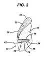
- FIG. 2is a cross-sectional view of the suture anchor of FIG. 1 implanted into a bone;
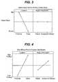
- FIG. 3is a graph of failure modes with respect to the location and angle of a suture passing port of the suture anchor of FIG. 1 ;
- FIG. 4is a graph of fixation strength with respect to the location and angle of a suture passing port of the suture anchor of FIG. 1 ;
- FIG. 5is a graph of fixation strength versus bone quality for several threading options of the suture anchor of FIG. 1 ;
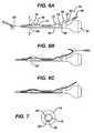
- FIGS. 6 A to Care side sectional views of the suture anchor of FIG. 1 and a driver therefor;
- FIG. 7is a cross-section taken along lines 7 - - 7 of FIG. 6A ;
- FIG. 8is a perspective view of an alternate driver head according to the present invention.
- FIG. 9is a wire drawing in perspective of the driver head of FIG. 8 received within a further embodiment of a suture anchor according to the present invention.
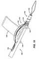
- FIG. 10is a close-up perspective view of the driver and suture anchor of FIG. 9 ;
- FIG. 11is a perspective view of the driver and suture anchor of FIG. 9 ;
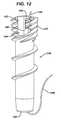
- FIG 12is a front plan view of a further embodiment of a suture anchor according to the present invention.
- FIG. 13is a sectional view taken along lines 13 - - 13 of FIG. 11 ;
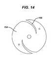
- FIG. 14is an end view of a further embodiment of a suture retaining clutch according to the present invention.
- FIG. 15is an end view of a further embodiment of a suture retaining clutch according to the present invention.
- FIG. 16Ais a front elevation view of a further embodiment of a suture retaining clutch according to the present invention.
- FIG.. 16Bis an end view from a distal end of the suture retaining clutch of FIG. 16A ;
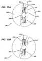
- FIGS. 17 A and Bare sectional views of a further embodiment of a suture retaining clutch according to the present invention.
- FIG. 18Ais a perspective view of a suture driver handle embodying a further embodiment of a suture retaining clutch according to the present invention.
- FIG. 18Bis an end view from a proximal end of the suture driver handle of FIG. 18A ;
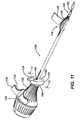
- FIG. 19is a side elevation view of a suture threader according to the present invention.
- FIG. 20is a side elevation view of an alternate usage of the suture threader of FIG. 19 ;
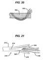
- FIG. 21is a side elevation view of a further embodiment of a suture threader according to the present invention.
- FIG. 22 A to Dillustrate a further embodiment of a suture threader according to the present invention
- FIG. 23Ais a top plan view of a further embodiment of a suture threader according to the present invention showing the braided tube in partial cut-awy;
- FIG. 23Bis an end view of the suture threader of FIG. 23A .
- FIG. 1depicts a knotless suture anchor 10 according to the present invention. It comprises a body 12 having a distal end 14 and proximal end 16. The proximal end 16 has a hexagonal-shaped tool receiving recess 18. It will be understood to one of skill in the art that alternative tool engagements may be employed. A slight inward taper 19 is provided at the distal end 14 to ease insertion of the anchor 10 into a bone hole (not shown in FIG. 1 ) and provides an initial fixation of the suture (not shown in FIG. 1 ) prior to threading the anchor into the hole.
- the body 12has a distal threaded portion 20 and a proximal threaded portion 22.
- a single exterior thread 24threads about the body 12 to form the distal threaded section 20.
- This thread 24extends nearly to the distal end 14, ending about 0.1 to 0.3 inches short thereof for easier insertion into a bone hole (not shown in FIG 1 ).
- one or more additional thread leads 26begin towards the proximal end 16 to form a multi-fluted threading which distinguishes the proximal threaded portion 22.
- Each individual thread start 24 and 26have the same pitch as the thread 24 in the distal threaded section 20, the presence of the one or more additional thread leads 26 provides the proximal threaded portion 22 with an increased effective thread pitch.
- each thread lead in the proximal threaded portion 22remains the same as the pitch of the thread 24 to eliminate axial compression effects from the threads as the anchor 10 is threaded into a bone hole.
- the major diameter of the proximal threaded portion 22is preferably somewhat larger than that of the distal threaded portion 20. Rather than have threads with a sharp outer edge the threads 24 and 26 preferably have a rounded our blunted profile to minimize stress on suture that is compressed against them.
- anchor body 12is shown with threads 24 and 26, especially for smaller diameters, the threads could be replaced with annular flanges or other purchase enhancements appropriate for a push-in anchor versus a threaded anchor. Even with the threads 24 and 26, smaller diameters of the anchor body 12 may be appropriate to push in rather than thread in.
- a lateral port 28passes through the body 12 at an oblique angle to a distally extending longitudinal axis 30 of the body 12 and is disposed within the proximal threaded portion 22. It provides for passage of suture (not shown in FIG. 1 ) between an inner axial cannulation 32 through the body 12 and an exterior 35 of the body 12. Such function will be explained in detail below.
- the body 12is formed of a suitable biocompatible material and is preferably provided sterile and packaged within a bacteria-proof enclosure (not shown) such that it is ready for a sterile surgical procedure.
- Many biodegradable materialshave less strength and are more brittle than non-biodegradable materials such as PEEK or stainless steel.
- the simple design of the body 12, without complicated moving or interacting parts,allows easier use of such biodegradable materials while maintaining the structural integrity of the anchor 10.
- novel suture anchors of the present inventionmay be made from a metallic material, a non-biodegradable polymer, a biodegradable polymer, or a composite of a biodegradable polymer or copolymer and a bioceramic.
- biodegradableas used herein is defined to mean materials that degrade in the body and then are either absorbed into or excreted from the body.
- bioceramicas defined herein is defined to mean ceramic and glass materials that are compatible with body tissue. The bioceramics are preferably biodegradable.
- the metallic materials that can be used to manufacture the anchors of the present inventioninclude stainless steel, titanium, alloys of nickel and titanium, or other biocompatible metallic materials.
- the non-biodegradable materials that can be used to manufacture the anchors of the present inventioninclude polyethylene, polypropylene, PEEK, or other biocompatible non-absorbable polymers.
- the biodegradable polymers that can be used to manufacture the anchors used in the present inventioninclude biodegradable polymers selected from the group consisting of aliphatic polyesters, polyorthoesters, polyanhydrides, polycarbonates, polyurethanes, polyamides and polyalkylene oxides.
- the biodegradable polymersare aliphatic polyester polymers and copolymers, and blends thereof.
- the aliphatic polyestersare typically synthesized in a ring opening polymerization.
- Suitable monomersinclude but are not limited to lactic acid, lactide (including L-, D-, meso and D,L mixtures), glycolic acid, glycolide, .epsilon.-caprolactone, p-dioxanone (1,4-dioxan-2-one), trimethylene carbonate (1,3-dioxan-2-one), .delta.-valerolactone, and combinations thereof.
- the bioceramics that can be used in the composite anchors of the present inventioninclude ceramics comprising mono-, di-, tri-, .alpha.-tri-, .beta.-tri-, and tetra-calcium phosphate, hydroxyapatite, calcium sulfates, calcium oxides, calcium carbonates, magnesium calcium phosphates. It is particularly preferred to use a .beta.-tritricalcium phosphate.
- bioglassesmay also be used in the composite screws.
- the bioglassesmay include phosphate glasses and bioglasses.
- Suitable biocompatible synthetic polymerscan include polymers selected from the group consisting of aliphatic polyesters, poly(amino acids), copoly(ether-esters), polyalkylene oxalates, polyamides, tyrosine derived polycarbonates, poly(iminocarbonates), polyorthoesters, polyoxaesters, polyamidoesters, polyoxaesters containing amine groups, poly(anhydrides), polyphosphazenes, polyurethanes, poly(ether urethanes), poly(ester urethanes), poly(propylene fumarate), poly(hydroxyalkanoate) and blends thereof.
- aliphatic polyestersinclude, but are not limited to, homopolymers and copolymers of lactide (which includes lactic acid, D-,L- and meso lactide); glycolide (including glycolic acid); .epsilon.-caprolactone; p-dioxanone (1,4-dioxan-2-one); trimethylene carbonate (1,3-dioxan-2-one); alkyl derivatives of trimethylene carbonate; .delta.-valerolactone; .beta.-butyrolactone; .gamma.-butyrolactone; .epsilon.-decalactone; hydroxybutyrate; hydroxyvalerate; 1,4-dioxepan-2-one (including its dimer 1,5,8,12-tetraoxacyclotetradecane-7,14-dione); 1,5-dioxepan-2-one; 6,6-dimethyl-1,4-
- Additional exemplary polymer or polymer blendsinclude, by non-limiting example, a polydioxanone, a polyhydroxybutyrate-co-hydrox- yvalerate, polyorthocarbonate, a polyaminocarbonate, and a polytrimethylene carbonate.
- Aliphatic polyesters used in the present inventioncan be homopolymers or copolymers (random, block, segmented, tapered blocks, graft, triblock, etc.) having a linear, branched or star structure.
- Poly(iminocarbonates), for the purpose of this inventionare understood to include those polymers as described by Kemnitzer and Kohn, in the Handbook of Biodegradable Polymers, edited by Domb, et. al., Hardwood Academic Press, pp. 251-272 (1997 ).
- Copoly(ether-esters), for the purpose of this inventionare understood to include those copolyester-ethers as described in the Journal of Biomaterials Research, Vol.
- Polyalkylene oxalatesfor the purpose of this invention, include those described in U.S. Pat. Nos. 4,208,511 ; 4,141,087 ; 4,130,639 ; 4,140,678 ; 4,105,034 ; and 4,205,399 .
- Polyphosphazenesco-, ter- and higher order mixed monomer based polymers made from L-lactide, D,L-lactide, lactic acid, glycolide, glycolic acid, para-dioxanone, trimethylene carbonate and E-caprolactone such as are described by Allcock in The Encyclopedia of Polymer Science, Vol. 13, pages 31-41, Wiley Intersciences, John Wiley & Sons, 1988 and by Vandorpe, et al in the Handbook of Biodegradable Polymers, edited by Domb, et al., Hardwood Academic Press, pp. 161-182 (1997 ).
- Polyanhydridesinclude those derived from diacids of the form HOOC--C.sub.6H.sub.4--O--(-CH.sub.2).sub.m--O--C.sub.6H.sub.4--COOH, where "m" is an integer in the range of from 2 to 8, and copolymers thereof with aliphatic alpha-omega diacids of up to 12 carbons.
- Polyoxaesters, polyoxaamides and polyoxaesters containing amines and/or amido groupsare described in one or more of the following U.S. Pat. Nos.
- the suture anchor 10is shown disposed within a bone hole 34 with a length of suture 36 passing through the anchor body 12 and also through a tendon (such as a tendon in a rotator cuff) 38.
- a loop 40 of the suture 36passes through the tendon 38 and its free ends 42 then pass down along a first side 44 of the anchor body 12, being trapped between the anchor body 12, especially by the threads 24 and 26, and bone 46 forming the bone hole 32.
- the free ends 42then pass over the distal end 14, into the axial cannulation 32 and then back out of the cannulation 32 through the lateral port 28. From here they pass between a second side 48 of the anchor body 12, being trapped between the body 12 and the bone 46.
- Other threading arrangementsare possible.
- a second anchor, or row of anchorscan be placed beneath the tendon 38 with the suture 36 passing from these anchor(s) up through the tendon 38 and to the anchor body 12 or to multiple anchor bodies 12.
- the location of the lateral port 28affects the strength of the fixation of the anchor body 12 to the bone 46 and also the affixation of the suture 36 to the bone 46 and body 12.
- a more distal location of the port 28provides higher fixation strength but the failure mode then tends to be evulsion of the anchor body 12 from the bone hole 34.
- a failure mode which involves slipping of the suture 36 rather than evulsion of the anchor body 12is preferred so as to not leave a foreign body free within a patient's joint in an event of failure. Also, an evulsion failure could lead to damage of the bone 46.
- the angle at which the port 28 passes through the body 12 with respect to the longitudinal axis 30affects fixation strength with a more oblique angle enhancing fixation.
- the size and direction which the port 28 passes through the bodycan affect the functionality and fixation strength of the design.
- the cross sectional area of the port 28is provided with sufficient dimension to pass a desired size and quantity of suture(s) through the port 28.
- the port 28should not be so small as to damage the suture(s) while transiting the port 28 during loading, deployment or in use. Similarly, passing a disproportionate quantity of suture through an undersized port 28 may result in damage to the anchor body 12 itself.
- the port 28should not be so large as to minimize the benefit to fixation strength which is derived from the meandering course of suture 36 through the system. An excessively large port size may result in an undesirable degradation of the structural strength of the anchor body.
- the size of the portmay be optimized to provide ease of use and avert damage to the system, while providing benefit within the context of additional fixation strength.
- the direction of the port 28may be optimally provided in a compound, oblique direction and offset location with respect to the longitudinal axis.
- the compound oblique direction and offset locationprovide an exit of the port 28 which coarsely approximates the tangent of the helices of the thread starts in a distal-to-proximal direction.
- FIG. 5one can see that the number of thread leads 26 in the proximal threaded section 22 affects suture 36 fixation between the bone 46 and the anchor body 12. More thread leads enhance such suture 36 fixation.
- the top lineshows optimal fixation with four leads, the thread 24 and three additional thread leads 26.
- anchor body 12 fixation and suture 36 fixationare optimized to provide maximum anchor body 12 fixation while still providing suture 36 slip as the predominate failure mode over anchor body 12 evulsion.
- the drivercomprises an elongated cannula 52 having a driving handle 54 at a proximal portion 56 thereof and a driver tip 58 at a distal portion 59 thereof.
- the driver tip 58engages the tool recess 18 on the anchor body 12.
- the driver tip 58is keyed to the anchor body tool recess 18 in such a fashion that the anchor body 12 is placed onto the driver 50 in only one rotational orientation such that a surgeon can determine such orientation by the rotational position of the handle 54. (See FIG. 7 in which a spline 60 on the driver tip 58 fits into a spline receiving cut-out 62 on the anchor boy 12.
- a suture passer 64such as the CHIA PERCPASSER (available from DePuy Mitek, Inc., Raynham, MA), an elongated braided Nitinol wire 66 with a distal suture grasping loop or kite 68, is engaged to the driver 50 and anchor body 12. It passes into a central lumen 70 of the cannula 52 from a proximal slot 72, out of the lumen 70 from a distal slot 74, over a removable ramp 76 and into the anchor body cannulation 32 through the lateral port 28, with the suture loop 68 extending out of the distal end 14 of the body 12.
- the wire 66is flexible but retains some rigidity and the ramp 76 provides a smooth entry angle into the lateral port 28.
- a tensioning clutch 78is interposed between the handle 54 and the cannula 52.
- a proximal portion 80 of the wire 66passes through a suture management passage 82 through the clutch 78.
- the free ends 42are loaded into the suture passer 64 it is drawn up the cannula 52 leaving the free ends 42 to pass up through the anchor body cannulation 32 from its distal end 14, out through the lateral port 28, over the ramp 76, into the lumen 70 through the distal slot 72, out of the lumen 70 through the proximal slot 72 and through the clutch suture management passage 82 as depicted in FIG. 6B .
- the ramp 76no longer being needed is removed as shown in FIG. 6C .
- the ramp 76fits to the cannula 52 via a snap-fit to provide easy removal.
- the anchoris now ready for implantation.
- the suture 36is tensioned through the suture tension clutch 78 to a desired tension.
- the anchor body 12is then threaded into the pre-drilled bone hole 34 via the driver 50.
- the clutch 78plays out the free ends 42 as the body 12 approaches and enters the hole 34 to maintain proper tension on the suture 36 and allows the suture 36 to move into the bone hole 34 from the clutch 78 rather than from the tissue and thus avoids spooling of the suture 36 onto the anchor body 12 as it is threaded into the hole 34.
- the anchor bodypreferably completes only a partial turn, such as one quarter turn from the time the suture 36 is pinched by the port 28 entering the hole 34 and the anchor body 12 is fully seated therein.
- the anchor body 12, especially in its interior, and the suture 36can be formed of materials or have their surfaces enhanced with materials or procedures which lower friction and enhance slipping of the suture 36 as the anchor is deployed.
- the proximal end 22 of the anchor body 12is preferably below the bone 46 within the bone hole 34.
- the driver 50is removed and the free ends 42 trimmed leaving the anchor 10 in place as shown in FIG. 2 .
- FIG. 8illustrates an alternative embodiment of an insertion tool 100
- FIG. 9illustrates an alternative embodiment of an anchor 102 according to the present invention, each of these being adapted for use together.
- the anchor 102has a structure similar to the anchor 10 with the exception of an axial boss 104 within its axial cannulation 106 which mates with a distal axial slot 108 in a distal driving portion 110 of the insertion tool 100.
- the axial cannulationis enlarged radially where the driving portion 110 is received such that an interior cannulation 112 of the driving portion 110 has the same interior diameter as a distal portion 114 the anchor axial cannulation 106 and the boss 104 extends radially into the slot 108 to a depth matching the interior diameter of the interior cannulation 112, providing a smooth transition within the of the interior cannulation 112 and axial cannulation 106 eliminating discontinuities upon which suture can snag during rotational deployment of the anchor 102.
- the boss 104provides additional engagement between the insertion tool 100 and the anchor 102.
- the boss 104aligns circumferentially with a lateral port 116 on the anchor.
- a suture ramp 118aligns on the insertion tool 100 with the port 116. The alignment of the boss 104 with respect to the port 116 and the slot 108 with respect to the ramp 118 puts the port 116 and ramp 118 into circumferential alignment with one another.
- the ramp 118is formed of a molded polymer having an arcuate suture receiving groove 120 which extends radially outwardly to guide suture and/or a suture grasper 122 out of a slot 124 on the insertion tool 100 and into the port 116 without sharp transitions and with the suture or suture grasper 122 forming an oblique angle with respect to itself as it enters the port 116.
- the ramp 118also bears a pair of C-shaped snap clips 126 which snap onto and off of the insertion tool 100 for easy removal of the ramp 118 during the procedure previously described.
- a grasping tab 128provides a gripping surface for easy manual removal of the ramp 118 and also provides a surface upon which to place instructions for use.
- a T-shaped handle 130 on the suture grasper 122preferably has finger lands 132 for easy manipulation of the suture grasper 122.
- a suture clutch 134which normally holds the suture and then releases it as torque is provided to a handle 136 on the insertion tool 100 is shown distal of the handle 136 but could be incorporated therein. Details on preferred clutch mechanisms are provided later herein.
- FIG. 12illustrates a further embodiment of a suture anchor 140 according to the present invention. It is similar to the prior suture anchors 10 and 102; however, instead of a port it carries an axial slot 142 at its proximal end.
- the slot 142terminates at its distal end 144 with a return portion 146 which extends proximally and circumferentially along a path of a thread start 147 providing an overall hook shape to the slot 142.
- Being open at its proximal endallows for easier threading of a suture grasper (not shown in FIG. 12 ).
- Ease of threadingis so improved that the grasper can be omitted in which case during the procedure a surgeon can directly thread a suture 148 through a main axial cannulation 150 of the anchor 140, feeding it into the slot 142 and seating it within the slot return portion 146.
- a procedure with the anchor 140would proceed as previously described with the surgeon pre-drilling a hole in a bone and passing suture 148 through tissue, preferably in an arthroscopic procedure through a cannula (the cannula, tissue and bone not being shown in FIG. 12 ). With free ends of the suture 148 outside of the patient's body the surgeon passes them through the cannulation 150 and seats the suture within the return portion 146.
- the anchor 140would then be loaded onto an insertion tool such as the tool 100 or 50 and installed into the bone as previously described, the return portion 146 holding the suture similarly to the aforementioned ports.
- the return portionpasses into the cannulation 150 at an oblique angle as described with respect to the prior ports thus allowing the suture 148 to pass into the cannulation 150 through the return portion 146 while keeping an oblique angle with respect to itself.
- the clutch 134comprises a disk shaped body 152 having a distal portion 154 which attaches to an elongated cannula 156 which itself terminates in the hexagonal driving portion 110.
- a proximal portion 158 of the body 152attaches to the insertion tool handle 136 outwardly radially of where the cannula 156 attaches to the body 152.
- An axial slot 160leads into the body 152 and receives and grabs the suture 148.
- its interior surface 162is formed of a rubber or other resilient material to enhance the grip with the suture 148. Torque applied to the handle 136 is transmitted through the clutch body 152 to the cannula 156.
- the body 152is formed of a material, such as a hard rubber, having sufficient resilience to allow the slot 160 to open under the influence of such torque and relax the grip on the suture 148.
- the clutch 134normally grips the suture to maintain tension but relaxes that grip as the handle 136 is torqued during implantation of the anchor 140 allowing suture 148 to slide through the clutch 134.
- FIG. 14illustrates an alternate embodiment of a clutch body 164 according to the present invention. It comprises a pair of somewhat radial slots 166 which spiral inwardly radially in a direction in which torque would be applied to an associated handle (not shown in FIG. 14 ).
- FIG. 15illustrates a further embodiment of a clutch body 170 comprising a plurality of radially extending arms 172, each having circumferential suture receiving slots 174 therein.
- a cannula attachment location 176is located in the center of the body 170 and handle attachment locations 178 are located on the arms outwardly radially of the slots 174.
- FIGS. 16 A and Billustrate a further embodiment of a clutch mechanism 180 which comprises a rigid outer handle gripping portion 182 and a radially interior resilient insert 184.
- a proximal end 186 of the insert 184attaches to the outer handle 182 and a distal end 188 of the insert 184 attaches to a cannula 190.
- Suture 192feeds into a gap 194 between the outer handle 182 and the insert 184 through a radial slot 196 in the handle 182.
- the gap 194is sized to grip the suture 192.
- Application of torque to the outer handle 182twists the insert 184 thereby opening the gap 194 and allowing slippage of the suture 192 therethrough.
- FIGS. 17 A and Billustrate a further embodiment of a clutch mechanism 200 comprising a pair of radial flanges 202 extending outwardly radially from a cannula proximal portion 204.
- a resilient material 206such as rubber affixes to both sides of the flanges 202.
- An outer handle 208comprises two halves 210, each of which attach to one of the flanges 202 and which are spaced apart from the opposing flange 202 to create suture receiving slots 212.
- the slots 212can have flared openings 214 with a suture retaining lip 216 therein.
- Suture 218is gripped within the slots 212 by compression between the outer handle 208 and the resilient material 206 on the flange 202 as shown in FIG. 17 A .
- Application of torque to the outer handle 208compresses the resilient material between the handle 208 and flanges 202 to open the slots 212 to release the suture as shown in FIG. 17 B .
- FIGS. 18 A and Billustrate an additional embodiment of a clutch mechanism 220.
- a handle 222comprise an outer cylindrical gripping portion 224 and a central axial core 226, the gripping portion 224 being attached to the core 226 via a plurality of radial ribs 228.
- One pair of ribs 230extend slightly off axis and adjacent to each other and the gripping portion 224 is open between them forming a radially extending axial slot 232 in the handle 222.
- a retainer member 236sits within the slot 232 extending from one of the ribs 230 toward the adjacent rib 230.
- Threading the suture 148 through the cannulation 150 of the suture anchor 140 of FIG. 12can be accomplished manually without assistance from a threading device.
- a simple converging threader 300 as illustrated in FIG. 19can further simplify the procedure.
- the threader 300comprises an open braided tube 302 having one end 304 inserted through the cannulation 150 and a second expanded end 306 into which one or more sutures 148 can be pushed by hand.
- the threader 300is preferably woven from a flexible biocompatible material and provided in combination with the anchor 140, with the threader 300 received through the cannulation 150, and with both the threader 300 and anchor being sterile and packaged within a sterile bacteria-proof package (not shown).
- the sutures 148can be merely stitched through the braided tube 302. If the weave is open enough they can be stitched by hand or they can be stitched with needles (not shown). The tube 302 is then drawn through the cannulation 150 as in FIG. 19 .
- a threader 310can be formed from a tube 312 which is not necessarily braided but rather provided with axial slits 314 at one end 316 to form a mouth 318 for receiving the suture 148. Gripping enhancements such as teeth 320 can be provided within the mouth 318 to help retain the suture 148 therein as the threader 310 passes through the cannulation 150.
- a simple spring metal snap element 322can be provided to a braided tube 324, the element 322 having a first open position as shown in FIG. 22B and a second relaxed closed position as shown in FIG. 22C .
- a loading suture loop 324can be employed about the element 322 to provide the squeezing force for closure and also to further compress the sutures 148 within the tube 324.
- a separate loading suture loop 324can also be provided alone and woven through the braid of the tube 324 in substitution of the element 322.
- the braiding of the tube 324can be woven to encourage closure, especially if the material is resilient, and to hold the expanded end 316 open a stretcher 326 can be inserted therein as shown in FIGS. 23 A and B .
- the stretcher 326comprises a tube 328 having a full length side opening 330 whereby after the suture 148 is loaded into the expanded end 316 the tube 328 is removed therefrom with the suture 148 passing through the opening 330 to allow removal of the tube 328.
Landscapes
- Health & Medical Sciences (AREA)
- Surgery (AREA)
- Life Sciences & Earth Sciences (AREA)
- Medical Informatics (AREA)
- Nuclear Medicine, Radiotherapy & Molecular Imaging (AREA)
- Engineering & Computer Science (AREA)
- Biomedical Technology (AREA)
- Heart & Thoracic Surgery (AREA)
- Molecular Biology (AREA)
- Animal Behavior & Ethology (AREA)
- General Health & Medical Sciences (AREA)
- Public Health (AREA)
- Veterinary Medicine (AREA)
- Rheumatology (AREA)
- Surgical Instruments (AREA)
- Prostheses (AREA)
Abstract
Description
- This application relates to suture anchors and more particularly to knotless suture anchors.
- Suture anchors are commonly employed to attach soft tissue such as tendons or ligaments to bone. For instance, in a rotator cuff repair suture is passed through a detached or damaged portion of a rotator cuff tendon. A suture anchor is implanted into the adjacent bone. By attaching the suture to the anchor the tendon is pulled into contact with the bone to promote adhesion of the tendon to the bone.
- Such procedures are often performed arthroscopically through a narrow cannula. This reduces trauma to the patient but makes attachment of the suture to the anchor using a knot more difficult. Knotless suture anchors may be employed which allow a surgeon to tension the suture to a desired degree and then affix to suture to the anchor without having to tie a knot. A typical knotless anchor is shown in
US Patent Publication No. 20080033460 wherein the suture is trapped between an inner member and outer member of an anchor in coaxial relation to one another. While such anchors work well their complexity increases manufacturing cost and makes it difficult to form the anchor of bioabsorbable materials which often are more frangible and less strong than metals or traditional polymers. - A suture anchor assembly according to the present invention comprises a suture anchor comprising a tubular body having an axial bore therethrough and one or more purchase enhancements on an exterior surface of the body adapted to enhance purchase of the body within a bone hole. A lateral port passes through the body from the bore to the exterior surface. A driver engages to a proximal portion of the body and bears a suture passer comprising an elongated flexible member passing along the driver, along an exterior of the body at its proximal portion, through the lateral port and into the axial bore with a distal end of the threader extending out of a distal section of the axial bore and bearing a suture engager.
- Preferably, the suture engager comprises a loop through which the suture can be threaded. Also preferably, the body and the driver are sterile and are packaged together in a bacteria proof sterile enclosure. Preferably, the one or more purchase enhancements comprise at least one screw thread about the exterior surface. More preferably, a proximal portion of the body carries a multi-fluted external thread.
- Preferably, an engagement between the driver and the suture anchor provides for the suture anchor to be torqued into a bone by the driver.
- Preferably, a ramp is provided on the driver adjacent the suture anchor, the ramp extending outwardly radially of the driver with the elongated flexible member passing over the ramp and into the port whereby to minimize bends in the suture threader as it passes into the port. Preferably, the ramp further comprises a open groove receiving the elongated flexible member. Preferably, the ramp is removable from the driver, such as by fitting onto the driver with a snap fit.
- A method according to the present invention provides for affixing tissue to bone. The method comprises the steps of: passing a length of suture through the tissue; loading the length of suture into suture anchor assembly, the suture anchor assembly comprising: a suture anchor which comprises a tubular body with an axial bore therethrough and a lateral port through the body from the bore to an exterior surface of the body, the suture; a driver engaged to a proximal portion of the body; and a suture passer comprising an elongated flexible member passing along the driver, along an exterior of the body at its proximal portion, through the lateral port and into the axial bore with a distal end of the threader extending out of a distal section of the axial bore and bearing a suture engager; the step of loading comprising passing the length of suture through the suture engager; pulling the suture passer to pull the suture engaged in its suture engager through the suture anchor body axial bore and out of the later port; implanting the suture anchor into the bone via the driver.
- Preferably, the suture engager comprises a loop and the step of loading comprises passing the length of suture through the loop. Also preferably, the body and the driver are sterile and are packaged together in a bacteria proof sterile enclosure and they are removed from the enclosure prior to the step loading.
- Preferably, implanting the suture anchor into the bone comprises threading the suture anchor into the bone via the driver.
- Preferably, the driver further comprises a ramp adjacent the suture anchor, the ramp extending outwardly radially of the driver with the elongated flexible member passing over the ramp and into the port. The method also then further comprises the step of removing the ramp prior to the step of embedding.
FIG. 1 is a front plan view of a suture anchor according to the present invention;FIG. 2 is a cross-sectional view of the suture anchor ofFIG. 1 implanted into a bone;FIG. 3 is a graph of failure modes with respect to the location and angle of a suture passing port of the suture anchor ofFIG. 1 ;FIG. 4 is a graph of fixation strength with respect to the location and angle of a suture passing port of the suture anchor ofFIG. 1 ;FIG. 5 is a graph of fixation strength versus bone quality for several threading options of the suture anchor ofFIG. 1 ;FIGS. 6 A to C are side sectional views of the suture anchor ofFIG. 1 and a driver therefor;FIG. 7 is a cross-section taken along lines 7 - - 7 ofFIG. 6A ;FIG. 8 is a perspective view of an alternate driver head according to the present invention;FIG. 9 is a wire drawing in perspective of the driver head ofFIG. 8 received within a further embodiment of a suture anchor according to the present invention;FIG. 10 is a close-up perspective view of the driver and suture anchor ofFIG. 9 ;FIG. 11 is a perspective view of the driver and suture anchor ofFIG. 9 ;FIG 12 is a front plan view of a further embodiment of a suture anchor according to the present invention;FIG. 13 is a sectional view taken along lines 13 - - 13 ofFIG. 11 ;FIG. 14 is an end view of a further embodiment of a suture retaining clutch according to the present invention;FIG. 15 is an end view of a further embodiment of a suture retaining clutch according to the present invention;FIG. 16A is a front elevation view of a further embodiment of a suture retaining clutch according to the present invention;FIG.. 16B is an end view from a distal end of the suture retaining clutch ofFIG. 16A ;FIGS. 17 A and B are sectional views of a further embodiment of a suture retaining clutch according to the present invention;FIG. 18A is a perspective view of a suture driver handle embodying a further embodiment of a suture retaining clutch according to the present invention;FIG. 18B is an end view from a proximal end of the suture driver handle ofFIG. 18A ;FIG. 19 is a side elevation view of a suture threader according to the present invention;FIG. 20 is a side elevation view of an alternate usage of the suture threader ofFIG. 19 ;FIG. 21 is a side elevation view of a further embodiment of a suture threader according to the present invention;FIG. 22 A to D illustrate a further embodiment of a suture threader according to the present invention;FIG. 23A is a top plan view of a further embodiment of a suture threader according to the present invention showing the braided tube in partial cut-awy; andFIG. 23B is an end view of the suture threader ofFIG. 23A .FIG. 1 depicts aknotless suture anchor 10 according to the present invention. It comprises abody 12 having adistal end 14 andproximal end 16. Theproximal end 16 has a hexagonal-shapedtool receiving recess 18. It will be understood to one of skill in the art that alternative tool engagements may be employed. A slightinward taper 19 is provided at thedistal end 14 to ease insertion of theanchor 10 into a bone hole (not shown inFIG. 1 ) and provides an initial fixation of the suture (not shown inFIG. 1 ) prior to threading the anchor into the hole.- The
body 12 has a distal threadedportion 20 and a proximal threadedportion 22. Asingle exterior thread 24 threads about thebody 12 to form the distal threadedsection 20. Thisthread 24 extends nearly to thedistal end 14, ending about 0.1 to 0.3 inches short thereof for easier insertion into a bone hole (not shown inFIG 1 ). However, one or more additional thread leads 26 begin towards theproximal end 16 to form a multi-fluted threading which distinguishes the proximal threadedportion 22. Eachindividual thread start thread 24 in the distal threadedsection 20, the presence of the one or more additional thread leads 26 provides the proximal threadedportion 22 with an increased effective thread pitch. However, the pitch of each thread lead in the proximal threadedportion 22 remains the same as the pitch of thethread 24 to eliminate axial compression effects from the threads as theanchor 10 is threaded into a bone hole. Preferably, there are four thread leads in the proximal threadedportion 22, thethread 24 and three additional thread leads 26. The major diameter of the proximal threadedportion 22 is preferably somewhat larger than that of the distal threadedportion 20. Rather than have threads with a sharp outer edge thethreads anchor body 12 is shown withthreads threads anchor body 12 may be appropriate to push in rather than thread in. - A
lateral port 28 passes through thebody 12 at an oblique angle to a distally extendinglongitudinal axis 30 of thebody 12 and is disposed within the proximal threadedportion 22. It provides for passage of suture (not shown inFIG. 1 ) between an inneraxial cannulation 32 through thebody 12 and anexterior 35 of thebody 12. Such function will be explained in detail below. - The
body 12 is formed of a suitable biocompatible material and is preferably provided sterile and packaged within a bacteria-proof enclosure (not shown) such that it is ready for a sterile surgical procedure. Many biodegradable materials have less strength and are more brittle than non-biodegradable materials such as PEEK or stainless steel. The simple design of thebody 12, without complicated moving or interacting parts, allows easier use of such biodegradable materials while maintaining the structural integrity of theanchor 10. - The novel suture anchors of the present invention may be made from a metallic material, a non-biodegradable polymer, a biodegradable polymer, or a composite of a biodegradable polymer or copolymer and a bioceramic. The term biodegradable as used herein is defined to mean materials that degrade in the body and then are either absorbed into or excreted from the body. The term bioceramic as defined herein is defined to mean ceramic and glass materials that are compatible with body tissue. The bioceramics are preferably biodegradable.
- The metallic materials that can be used to manufacture the anchors of the present invention include stainless steel, titanium, alloys of nickel and titanium, or other biocompatible metallic materials.
- The non-biodegradable materials that can be used to manufacture the anchors of the present invention include polyethylene, polypropylene, PEEK, or other biocompatible non-absorbable polymers.
- The biodegradable polymers that can be used to manufacture the anchors used in the present invention include biodegradable polymers selected from the group consisting of aliphatic polyesters, polyorthoesters, polyanhydrides, polycarbonates, polyurethanes, polyamides and polyalkylene oxides. Preferably, the biodegradable polymers are aliphatic polyester polymers and copolymers, and blends thereof. The aliphatic polyesters are typically synthesized in a ring opening polymerization. Suitable monomers include but are not limited to lactic acid, lactide (including L-, D-, meso and D,L mixtures), glycolic acid, glycolide, .epsilon.-caprolactone, p-dioxanone (1,4-dioxan-2-one), trimethylene carbonate (1,3-dioxan-2-one), .delta.-valerolactone, and combinations thereof.
- The bioceramics that can be used in the composite anchors of the present invention include ceramics comprising mono-, di-, tri-, .alpha.-tri-, .beta.-tri-, and tetra-calcium phosphate, hydroxyapatite, calcium sulfates, calcium oxides, calcium carbonates, magnesium calcium phosphates. It is particularly preferred to use a .beta.-tritricalcium phosphate. In addition to bioceramics, bioglasses may also be used in the composite screws. The bioglasses may include phosphate glasses and bioglasses.
- Suitable biocompatible synthetic polymers can include polymers selected from the group consisting of aliphatic polyesters, poly(amino acids), copoly(ether-esters), polyalkylene oxalates, polyamides, tyrosine derived polycarbonates, poly(iminocarbonates), polyorthoesters, polyoxaesters, polyamidoesters, polyoxaesters containing amine groups, poly(anhydrides), polyphosphazenes, polyurethanes, poly(ether urethanes), poly(ester urethanes), poly(propylene fumarate), poly(hydroxyalkanoate) and blends thereof.
- For the purpose of this invention aliphatic polyesters include, but are not limited to, homopolymers and copolymers of lactide (which includes lactic acid, D-,L- and meso lactide); glycolide (including glycolic acid); .epsilon.-caprolactone; p-dioxanone (1,4-dioxan-2-one); trimethylene carbonate (1,3-dioxan-2-one); alkyl derivatives of trimethylene carbonate; .delta.-valerolactone; .beta.-butyrolactone; .gamma.-butyrolactone; .epsilon.-decalactone; hydroxybutyrate; hydroxyvalerate; 1,4-dioxepan-2-one (including its
dimer U.S. Pat. Nos. 4,208,511 ;4,141,087 ;4,130,639 ;4,140,678 ;4,105,034 ; and4,205,399 . Polyphosphazenes, co-, ter- and higher order mixed monomer based polymers made from L-lactide, D,L-lactide, lactic acid, glycolide, glycolic acid, para-dioxanone, trimethylene carbonate and E-caprolactone such as are described byAllcock in The Encyclopedia of Polymer Science, Vol. 13, pages 31-41, Wiley Intersciences, John Wiley & Sons, 1988 and byVandorpe, et al in the Handbook of Biodegradable Polymers, edited by Domb, et al., Hardwood Academic Press, pp. 161-182 (1997). Polyanhydrides include those derived from diacids of the form HOOC--C.sub.6H.sub.4--O--(-CH.sub.2).sub.m--O--C.sub.6H.sub.4--COOH, where "m" is an integer in the range of from 2 to 8, and copolymers thereof with aliphatic alpha-omega diacids of up to 12 carbons. Polyoxaesters, polyoxaamides and polyoxaesters containing amines and/or amido groups are described in one or more of the followingU.S. Pat. Nos. 5,464,929 ;5,595,751 ;5,597,579 ;5,607,687 ;5,618,552 ;5,620,698 ;5,645,850 ;5,648,088 ;5,698,213 ;5,700,583 ; and5,859,150 . Polyorthoesters such as those described byHeller in Handbook of Biodegradable Polymers, edited by Domb, et al., Hardwood Academic Press, pp. 99-118 (1997). - Turning also to
FIG. 2 , thesuture anchor 10 is shown disposed within abone hole 34 with a length ofsuture 36 passing through theanchor body 12 and also through a tendon (such as a tendon in a rotator cuff) 38. Aloop 40 of thesuture 36 passes through thetendon 38 and its free ends 42 then pass down along afirst side 44 of theanchor body 12, being trapped between theanchor body 12, especially by thethreads bone 46 forming thebone hole 32. The free ends 42 then pass over thedistal end 14, into theaxial cannulation 32 and then back out of thecannulation 32 through thelateral port 28. From here they pass between asecond side 48 of theanchor body 12, being trapped between thebody 12 and thebone 46. Other threading arrangements are possible. For instance, rather than passing theloop 40 through the tendon 38 a second anchor, or row of anchors, (not shown) can be placed beneath thetendon 38 with thesuture 36 passing from these anchor(s) up through thetendon 38 and to theanchor body 12 or tomultiple anchor bodies 12. - Turning also to
FIGS. 3 and 4 , the location of thelateral port 28 affects the strength of the fixation of theanchor body 12 to thebone 46 and also the affixation of thesuture 36 to thebone 46 andbody 12. A more distal location of theport 28 provides higher fixation strength but the failure mode then tends to be evulsion of theanchor body 12 from thebone hole 34. A failure mode which involves slipping of thesuture 36 rather than evulsion of theanchor body 12 is preferred so as to not leave a foreign body free within a patient's joint in an event of failure. Also, an evulsion failure could lead to damage of thebone 46. The angle at which theport 28 passes through thebody 12 with respect to thelongitudinal axis 30 affects fixation strength with a more oblique angle enhancing fixation. - Additionally, the size and direction which the
port 28 passes through the body can affect the functionality and fixation strength of the design. The cross sectional area of theport 28 is provided with sufficient dimension to pass a desired size and quantity of suture(s) through theport 28. Theport 28 should not be so small as to damage the suture(s) while transiting theport 28 during loading, deployment or in use. Similarly, passing a disproportionate quantity of suture through anundersized port 28 may result in damage to theanchor body 12 itself. Conversely, theport 28 should not be so large as to minimize the benefit to fixation strength which is derived from the meandering course ofsuture 36 through the system. An excessively large port size may result in an undesirable degradation of the structural strength of the anchor body. The size of the port may be optimized to provide ease of use and avert damage to the system, while providing benefit within the context of additional fixation strength. - It is favorable to choose the direction of the
port 28 as it passes through the body at such angles and locations which promote passage ofsuture 36 through the system. Obtuse angles formed by thesuture 36 during loading and use are most desirable, as they minimize contact friction at corners and subsequently, reduce loading forces and wear and increase robustness of the entire system. The direction of theport 28 may be optimally provided in a compound, oblique direction and offset location with respect to the longitudinal axis. The compound oblique direction and offset location provide an exit of theport 28 which coarsely approximates the tangent of the helices of the thread starts in a distal-to-proximal direction. - This direction and location has been shown to positively affect fixation strength. As the anchor is threaded into a bone hole, it is theorized that the compound oblique direction and offset location of the
port 28 promotes a gentle fold of thesuture 36 as it exits theport 28, causing thesuture 36 to fall easily within the roots between the proximal thread starts. In this context, aport 28 oriented radially normal to the longitudinal axis, for example, would require a sharp fold of thesuture 36 as it exits theport 28. The sharp fold thusly presents a sharp transition as the anchor descends into the bone hole past theport 28, thereby weakening the bone by shearing along the wall of the bone hole, ultimately reducing fixation. By not creating sharp bends in thesuture 36 it is possible to provide an anchor having smaller dimensions without adding too much additional stress to thesuture 36. - Other forms of providing a gentle transition may include the use of a "break edge", fillet or chamfer in the vicinity of the
port 28. However, in designs incorporating minimum wall thickness of the anchor, large transition features may result in undesirable increases in the cross sectional area of theport 28. - Turning also to
FIG. 5 , one can see that the number of thread leads 26 in the proximal threadedsection 22 affectssuture 36 fixation between thebone 46 and theanchor body 12. More thread leads enhancesuch suture 36 fixation. The top line shows optimal fixation with four leads, thethread 24 and three additional thread leads 26. - Ideally,
anchor body 12 fixation andsuture 36 fixation are optimized to providemaximum anchor body 12 fixation while still providingsuture 36 slip as the predominate failure mode overanchor body 12 evulsion. - Turning also now to
FIGS. 6A, 6B and 6C , thesuture anchor body 12 is shown loaded onto ananchor driver 50. The driver comprises anelongated cannula 52 having a drivinghandle 54 at aproximal portion 56 thereof and adriver tip 58 at adistal portion 59 thereof. Thedriver tip 58 engages thetool recess 18 on theanchor body 12. Preferably thedriver tip 58 is keyed to the anchorbody tool recess 18 in such a fashion that theanchor body 12 is placed onto thedriver 50 in only one rotational orientation such that a surgeon can determine such orientation by the rotational position of thehandle 54. (SeeFIG. 7 in which aspline 60 on thedriver tip 58 fits into a spline receiving cut-out 62 on theanchor boy 12. - A
suture passer 64, such as the CHIA PERCPASSER (available from DePuy Mitek, Inc., Raynham, MA), an elongatedbraided Nitinol wire 66 with a distal suture grasping loop orkite 68, is engaged to thedriver 50 andanchor body 12. It passes into acentral lumen 70 of thecannula 52 from aproximal slot 72, out of thelumen 70 from adistal slot 74, over aremovable ramp 76 and into theanchor body cannulation 32 through thelateral port 28, with thesuture loop 68 extending out of thedistal end 14 of thebody 12. Thewire 66 is flexible but retains some rigidity and theramp 76 provides a smooth entry angle into thelateral port 28. A tensioningclutch 78 is interposed between thehandle 54 and thecannula 52. Aproximal portion 80 of thewire 66 passes through asuture management passage 82 through the clutch 78. During a procedure, after thesuture 36 has been passed through thetendon 38, the free ends 42 are pulled out of the procedure cannula (not shown) to a point outside of the patient's body and loaded through thesuture loop 68. - After the free ends 42 are loaded into the
suture passer 64 it is drawn up thecannula 52 leaving the free ends 42 to pass up through theanchor body cannulation 32 from itsdistal end 14, out through thelateral port 28, over theramp 76, into thelumen 70 through thedistal slot 72, out of thelumen 70 through theproximal slot 72 and through the clutchsuture management passage 82 as depicted inFIG. 6B . Theramp 76 no longer being needed is removed as shown inFIG. 6C . Preferably, theramp 76 fits to thecannula 52 via a snap-fit to provide easy removal. The anchor is now ready for implantation. - To complete the procedure the
suture 36 is tensioned through the suture tension clutch 78 to a desired tension. Theanchor body 12 is then threaded into thepre-drilled bone hole 34 via thedriver 50. The clutch 78 plays out the free ends 42 as thebody 12 approaches and enters thehole 34 to maintain proper tension on thesuture 36 and allows thesuture 36 to move into thebone hole 34 from the clutch 78 rather than from the tissue and thus avoids spooling of thesuture 36 onto theanchor body 12 as it is threaded into thehole 34. The anchor body preferably completes only a partial turn, such as one quarter turn from the time thesuture 36 is pinched by theport 28 entering thehole 34 and theanchor body 12 is fully seated therein. Theanchor body 12, especially in its interior, and thesuture 36 can be formed of materials or have their surfaces enhanced with materials or procedures which lower friction and enhance slipping of thesuture 36 as the anchor is deployed. When fully deployed theproximal end 22 of theanchor body 12 is preferably below thebone 46 within thebone hole 34. Thedriver 50 is removed and the free ends 42 trimmed leaving theanchor 10 in place as shown inFIG. 2 . FIG. 8 illustrates an alternative embodiment of aninsertion tool 100 andFIG. 9 illustrates an alternative embodiment of ananchor 102 according to the present invention, each of these being adapted for use together. Theanchor 102 has a structure similar to theanchor 10 with the exception of anaxial boss 104 within itsaxial cannulation 106 which mates with a distalaxial slot 108 in adistal driving portion 110 of theinsertion tool 100. Also, the axial cannulation is enlarged radially where the drivingportion 110 is received such that aninterior cannulation 112 of the drivingportion 110 has the same interior diameter as adistal portion 114 the anchoraxial cannulation 106 and theboss 104 extends radially into theslot 108 to a depth matching the interior diameter of theinterior cannulation 112, providing a smooth transition within the of theinterior cannulation 112 andaxial cannulation 106 eliminating discontinuities upon which suture can snag during rotational deployment of theanchor 102. Theboss 104 provides additional engagement between theinsertion tool 100 and theanchor 102.- Turning also to
FIGS. 10 and11 , theboss 104 aligns circumferentially with alateral port 116 on the anchor. Asuture ramp 118 aligns on theinsertion tool 100 with theport 116. The alignment of theboss 104 with respect to theport 116 and theslot 108 with respect to theramp 118 puts theport 116 and ramp 118 into circumferential alignment with one another. - The
ramp 118 is formed of a molded polymer having an arcuatesuture receiving groove 120 which extends radially outwardly to guide suture and/or asuture grasper 122 out of aslot 124 on theinsertion tool 100 and into theport 116 without sharp transitions and with the suture orsuture grasper 122 forming an oblique angle with respect to itself as it enters theport 116. Theramp 118 also bears a pair of C-shaped snap clips 126 which snap onto and off of theinsertion tool 100 for easy removal of theramp 118 during the procedure previously described. A graspingtab 128 provides a gripping surface for easy manual removal of theramp 118 and also provides a surface upon which to place instructions for use. - As shown in
FIG. 11 a T-shapedhandle 130 on thesuture grasper 122 preferably has finger lands 132 for easy manipulation of thesuture grasper 122. Asuture clutch 134 which normally holds the suture and then releases it as torque is provided to ahandle 136 on theinsertion tool 100 is shown distal of thehandle 136 but could be incorporated therein. Details on preferred clutch mechanisms are provided later herein. FIG. 12 illustrates a further embodiment of asuture anchor 140 according to the present invention. It is similar to the prior suture anchors 10 and 102; however, instead of a port it carries anaxial slot 142 at its proximal end. Theslot 142 terminates at itsdistal end 144 with areturn portion 146 which extends proximally and circumferentially along a path of athread start 147 providing an overall hook shape to theslot 142. Being open at its proximal end allows for easier threading of a suture grasper (not shown inFIG. 12 ).- Ease of threading is so improved that the grasper can be omitted in which case during the procedure a surgeon can directly thread a
suture 148 through a mainaxial cannulation 150 of theanchor 140, feeding it into theslot 142 and seating it within theslot return portion 146. A procedure with theanchor 140 would proceed as previously described with the surgeon pre-drilling a hole in a bone and passingsuture 148 through tissue, preferably in an arthroscopic procedure through a cannula (the cannula, tissue and bone not being shown inFIG. 12 ). With free ends of thesuture 148 outside of the patient's body the surgeon passes them through thecannulation 150 and seats the suture within thereturn portion 146. Theanchor 140 would then be loaded onto an insertion tool such as thetool return portion 146 holding the suture similarly to the aforementioned ports. Preferably the return portion passes into thecannulation 150 at an oblique angle as described with respect to the prior ports thus allowing thesuture 148 to pass into thecannulation 150 through thereturn portion 146 while keeping an oblique angle with respect to itself. - The clutch 134 comprises a disk shaped
body 152 having adistal portion 154 which attaches to anelongated cannula 156 which itself terminates in thehexagonal driving portion 110. Aproximal portion 158 of thebody 152 attaches to the insertion tool handle 136 outwardly radially of where thecannula 156 attaches to thebody 152. Anaxial slot 160, as best seen inFIG. 13 , leads into thebody 152 and receives and grabs thesuture 148. Preferably itsinterior surface 162 is formed of a rubber or other resilient material to enhance the grip with thesuture 148. Torque applied to thehandle 136 is transmitted through theclutch body 152 to thecannula 156. Thebody 152 is formed of a material, such as a hard rubber, having sufficient resilience to allow theslot 160 to open under the influence of such torque and relax the grip on thesuture 148. Thus, the clutch 134 normally grips the suture to maintain tension but relaxes that grip as thehandle 136 is torqued during implantation of theanchor 140 allowingsuture 148 to slide through the clutch 134. FIG. 14 illustrates an alternate embodiment of aclutch body 164 according to the present invention. It comprises a pair of somewhatradial slots 166 which spiral inwardly radially in a direction in which torque would be applied to an associated handle (not shown inFIG. 14 ).FIG. 15 illustrates a further embodiment of aclutch body 170 comprising a plurality of radially extendingarms 172, each having circumferentialsuture receiving slots 174 therein. Acannula attachment location 176 is located in the center of thebody 170 and handleattachment locations 178 are located on the arms outwardly radially of theslots 174.FIGS. 16 A and B illustrate a further embodiment of aclutch mechanism 180 which comprises a rigid outerhandle gripping portion 182 and a radially interiorresilient insert 184. Aproximal end 186 of theinsert 184 attaches to theouter handle 182 and adistal end 188 of theinsert 184 attaches to acannula 190. Suture 192 feeds into agap 194 between theouter handle 182 and theinsert 184 through aradial slot 196 in thehandle 182. Thegap 194 is sized to grip thesuture 192. Application of torque to theouter handle 182 twists theinsert 184 thereby opening thegap 194 and allowing slippage of thesuture 192 therethrough.FIGS. 17 A and B illustrate a further embodiment of aclutch mechanism 200 comprising a pair ofradial flanges 202 extending outwardly radially from a cannulaproximal portion 204. Aresilient material 206 such as rubber affixes to both sides of theflanges 202. An outer handle 208 comprises twohalves 210, each of which attach to one of theflanges 202 and which are spaced apart from the opposingflange 202 to createsuture receiving slots 212. Theslots 212 can have flaredopenings 214 with asuture retaining lip 216 therein.Suture 218 is gripped within theslots 212 by compression between the outer handle 208 and theresilient material 206 on theflange 202 as shown inFIG. 17 A . Application of torque to the outer handle 208 compresses the resilient material between the handle 208 andflanges 202 to open theslots 212 to release the suture as shown inFIG. 17 B .FIGS. 18 A and B illustrate an additional embodiment of aclutch mechanism 220. Ahandle 222 comprise an outer cylindrical grippingportion 224 and a centralaxial core 226, the grippingportion 224 being attached to thecore 226 via a plurality ofradial ribs 228. One pair ofribs 230 extend slightly off axis and adjacent to each other and thegripping portion 224 is open between them forming a radially extendingaxial slot 232 in thehandle 222. Near aproximal end 234 of the handle 222 aretainer member 236 sits within theslot 232 extending from one of theribs 230 toward theadjacent rib 230. It has a flaredopening 238 and a retaininglip 240 to ease entry ofsuture 242 into theslot 232 with thelip 240 holding it from falling out. Aresilient material 244 in theslot 232 grips thesuture 242. Torque applied to thegripping portion 224 tends to open theslot 232 releasing the tension on thesuture 242.- Threading the
suture 148 through thecannulation 150 of thesuture anchor 140 ofFIG. 12 can be accomplished manually without assistance from a threading device. However, a simple convergingthreader 300 as illustrated inFIG. 19 can further simplify the procedure. Thethreader 300 comprises anopen braided tube 302 having oneend 304 inserted through thecannulation 150 and a second expandedend 306 into which one ormore sutures 148 can be pushed by hand. Thethreader 300 is preferably woven from a flexible biocompatible material and provided in combination with theanchor 140, with thethreader 300 received through thecannulation 150, and with both thethreader 300 and anchor being sterile and packaged within a sterile bacteria-proof package (not shown). When a surgeon is ready to loadsutures 148 into theanchor 140 the combination of theanchor 140 andthreader 300 are removed from the sterile package and thesutures 148 are pushed into the threader expandedend 306. Tension is applied to theother end 304 causing the expandedend 306 to close and travel through thecannulation 150 carrying thesutures 148 therethrough. The procedure can then be completed as aforementioned. - Alternatively, as shown in
FIG. 20 , thesutures 148 can be merely stitched through thebraided tube 302. If the weave is open enough they can be stitched by hand or they can be stitched with needles (not shown). Thetube 302 is then drawn through thecannulation 150 as inFIG. 19 . - As shown in
FIG. 21 , athreader 310 can be formed from atube 312 which is not necessarily braided but rather provided withaxial slits 314 at oneend 316 to form amouth 318 for receiving thesuture 148. Gripping enhancements such asteeth 320 can be provided within themouth 318 to help retain thesuture 148 therein as thethreader 310 passes through thecannulation 150. - To ensure good closure of the expanded
end 306 of thethreader 300 ofFIG. 19 it can be modified with additional closures as shown inFIGS. 22 A through D . For instance a simple springmetal snap element 322 can be provided to abraided tube 324, theelement 322 having a first open position as shown inFIG. 22B and a second relaxed closed position as shown inFIG. 22C . After insertion of thesutures 148 with theelement 322 in the open position is squeezed to pop it into the closed position. Aloading suture loop 324 can be employed about theelement 322 to provide the squeezing force for closure and also to further compress thesutures 148 within thetube 324. A separateloading suture loop 324 can also be provided alone and woven through the braid of thetube 324 in substitution of theelement 322. - Alternatively, the braiding of the
tube 324 can be woven to encourage closure, especially if the material is resilient, and to hold the expandedend 316 open astretcher 326 can be inserted therein as shown inFIGS. 23 A and B . In its simplest form thestretcher 326 comprises atube 328 having a fulllength side opening 330 whereby after thesuture 148 is loaded into the expandedend 316 thetube 328 is removed therefrom with thesuture 148 passing through theopening 330 to allow removal of thetube 328. - The invention has been described with reference to the preferred embodiments. Obviously, modifications and alterations will occur to others upon reading and understanding the preceding detailed description. It is intended that the invention be construed as including all such modifications and alterations insofar as they come within the scope of the appended claims or the equivalents thereof.
Claims (15)
- A suture anchor assembly comprising:a suture anchor comprising a tubular body having an axial bore therethroughone or more purchase enhancements on an exterior surface of the body adapted to enhance purchase of the body within a bone hole;a lateral port through the body from the bore to the exterior surface;a driver engaged to a proximal portion of the body and a suture passer comprising an elongated flexible member passing along the driver, along an exterior of the body at its proximal portion, through the lateral port and into the axial bore with a distal end of the suture passer extending out of a distal section of the axial bore and bearing a suture engager.
- A suture anchor assembly according to claim 1 wherein the suture engager comprises a loop through which the suture can be threaded.
- A suture anchor assembly according to claim 1 wherein the body and the driver are sterile and are packaged together in a bacteria proof sterile enclosure.
- A suture anchor assembly according to claim 1 wherein the one or more purchase enhancements comprise at least one screw thread about the exterior surface.
- A suture anchor assembly according to claim 4 and wherein a proximal portion of the body carries a multi-fluted external thread.
- A suture anchor assembly according to claim 1 and further comprising an engagement between the driver and the suture anchor to allow the suture anchor to be torqued into a bone by the driver.
- A suture anchor assembly according to claim 1 and further comprising a ramp on the driver adjacent the suture anchor, the ramp extending outwardly radially of the driver with the elongated flexible member passing over the ramp and into the port whereby to minimize bends in the suture threader as it passes into the port.
- The suture anchor assembly of claim 7 wherein the ramp further comprises a open groove receiving the elongated flexible member.
- The suture anchor assembly of claim 7 wherein the ramp is removable from the driver.
- The suture anchor assembly of claim 9 wherein the ramp fits onto the driver with a snap fit.
- A method for affixing tissue to bone comprising the steps of:passing a length of suture through the tissue;loading the length of suture into suture anchor assembly, the suture anchor assembly comprising:a suture anchor which comprises a tubular body with an axial bore therethrough and a lateral port through the body from the bore to an exterior surface of the body, the suture;a driver engaged to a proximal portion of the body; anda suture passer comprising an elongated flexible member passing along the driver, along an exterior of the body at its proximal portion, through the lateral port and into the axial bore with a distal end of the suture passer extending out of a distal section of the axial bore and bearing a suture engager;the step of loading comprising passing the length of suture through the suture engager;pulling the suture passer to pull the suture engaged in its suture engager through the suture anchor body axial bore and out of the later port;implanting the suture anchor into the bone via the driver.
- The method of claim 11 wherein the suture engager comprises a loop and wherein the step of loading comprises passing the length of suture through the loop.
- The method of claim 11 wherein the body and the driver are sterile and are packaged together in a bacteria proof sterile enclosure and further comprising the step of removing them from the enclosure prior to the step loading.
- The method of claim 11 wherein the step of implanting the suture anchor into the bone comprises threading the suture anchor into the bone via the driver.
- The method of claim 11 wherein the driver further comprises a ramp adjacent the suture anchor, the ramp extending outwardly radially of the driver with the elongated flexible member passing over the ramp and into the port and wherein the method further comprises the step of removing the ramp prior to the step of embedding.
Applications Claiming Priority (1)
| Application Number | Priority Date | Filing Date | Title |
|---|---|---|---|
| US12/871,324US8435264B2 (en) | 2010-08-30 | 2010-08-30 | Knotless suture anchor and driver |
Publications (3)
| Publication Number | Publication Date |
|---|---|
| EP2422713A2true EP2422713A2 (en) | 2012-02-29 |
| EP2422713A3 EP2422713A3 (en) | 2015-10-28 |
| EP2422713B1 EP2422713B1 (en) | 2018-09-26 |
Family
ID=44674336
Family Applications (1)
| Application Number | Title | Priority Date | Filing Date |
|---|---|---|---|
| EP11179061.4AActiveEP2422713B1 (en) | 2010-08-30 | 2011-08-26 | Knotless suture anchor and driver |
Country Status (7)
| Country | Link |
|---|---|
| US (4) | US8435264B2 (en) |
| EP (1) | EP2422713B1 (en) |
| JP (1) | JP5774415B2 (en) |
| CN (1) | CN102551822B (en) |
| AU (1) | AU2011213834B2 (en) |
| BR (1) | BRPI1104657B1 (en) |
| CA (1) | CA2750296A1 (en) |
Cited By (1)
| Publication number | Priority date | Publication date | Assignee | Title |
|---|---|---|---|---|
| WO2020058805A1 (en)* | 2018-09-21 | 2020-03-26 | DePuy Synthes Products, Inc. | Bone compression screws and related systems and methods |
Families Citing this family (44)
| Publication number | Priority date | Publication date | Assignee | Title |
|---|---|---|---|---|
| US10426456B2 (en) | 2009-07-17 | 2019-10-01 | Pivot Medical, Inc. | Method and apparatus for re-attaching the labrum to the acetabulum, including the provision and use of a novel suture anchor system |
| US11197663B2 (en) | 2009-07-17 | 2021-12-14 | Stryker Puerto Rico Limited | Method and apparatus for attaching tissue to bone, including the provision and use of a novel knotless suture anchor system |
| US9149268B2 (en) | 2009-07-17 | 2015-10-06 | Pivot Medical, Inc. | Method and apparatus for attaching tissue to bone, including the provision and use of a novel knotless suture anchor system |
| US10136884B2 (en) | 2009-07-17 | 2018-11-27 | Pivot Medical, Inc. | Method and apparatus for attaching tissue to bone, including the provision and use of a novel knotless suture anchor system, including a retractable sheath |
| US11246585B2 (en) | 2009-07-17 | 2022-02-15 | Stryker Puerto Rico Limited | Method and apparatus for attaching tissue to bone, including the provision and use of a novel knotless suture anchor system |
| US10238379B2 (en) | 2009-07-17 | 2019-03-26 | Pivot Medical, Inc. | Method and apparatus for attaching tissue to bone, including the provision and use of a novel knotless suture anchor system |
| US12232718B2 (en) | 2009-07-17 | 2025-02-25 | Stryker Puerto Rico Limited | Method and apparatus for attaching tissue to bone, including the provision and use of a novel knotless suture anchor system |
| US10058319B2 (en) | 2009-07-17 | 2018-08-28 | Pivot Medical, Inc. | Method and apparatus for attaching tissue to bone, including the provision and use of a novel knotless suture anchor system, including a novel locking element |
| US9179905B2 (en) | 2009-07-17 | 2015-11-10 | Pivot Medical, Inc. | Method and apparatus for re-attaching the labrum to the acetabulum, including the provision and use of a novel suture anchor system |
| CN103917183A (en) | 2011-06-29 | 2014-07-09 | 皮沃特医疗公司 | Method and apparatus for re-attaching the labrum to the acetabulum, including the provision and use of a novel suture anchor system |
| US20150272567A1 (en) | 2012-08-03 | 2015-10-01 | Stabilynx, Inc. | Devices, systems, and methods for attaching soft tissue to bone tissue |
| US8986327B2 (en)* | 2012-10-18 | 2015-03-24 | Smith & Nephew, Inc. | Flexible anchor delivery system |
| US10292694B2 (en) | 2013-04-22 | 2019-05-21 | Pivot Medical, Inc. | Method and apparatus for attaching tissue to bone |
| US9572563B2 (en) | 2013-07-08 | 2017-02-21 | Biomet Sports Medicine, LLC. | Suture anchor and related method |
| AU2014362199B2 (en) | 2013-12-12 | 2019-07-11 | Stryker Puerto Rico Limited | Method and apparatus for attaching tissue to bone, including the provision and use of a novel knotless suture anchor system |
| US20150173738A1 (en)* | 2013-12-23 | 2015-06-25 | Arthrex, Inc. | Surgical fixation device with antibacterial substance |
| US9980715B2 (en) | 2014-02-05 | 2018-05-29 | Trinity Orthopedics, Llc | Anchor devices and methods of use |
| US9907548B2 (en) | 2014-03-03 | 2018-03-06 | Tenjin LLC | Implant placement systems, devices and methods |
| US9770240B2 (en) | 2014-03-03 | 2017-09-26 | Tenjin LLC | Ceramic implant placement systems and superelastic suture retention loops for use therewith |
| US9226817B2 (en) | 2014-03-03 | 2016-01-05 | Tenjin LLC | Implant placement systems, devices, and methods |
| US9717587B2 (en) | 2014-03-03 | 2017-08-01 | Tenjin LLC | Multiple implant constructions and fixation methods associated therewith |
| US11504224B2 (en) | 2014-03-03 | 2022-11-22 | Tenjin LLC | Implant placement systems and one-handed methods for tissue fixation using same |
| US9782250B2 (en) | 2014-03-03 | 2017-10-10 | Tenjin LLC | Implant placement systems and one-handed methods for tissue fixation using same |
| US9566060B2 (en) | 2014-03-03 | 2017-02-14 | Tenjin LLC | Implant placement systems, devices and methods |
| US9974534B2 (en)* | 2015-03-31 | 2018-05-22 | Biomet Sports Medicine, Llc | Suture anchor with soft anchor of electrospun fibers |
| US10820918B2 (en) | 2015-07-17 | 2020-11-03 | Crossroads Extremity Systems, Llc | Transosseous guide and method |
| US10258401B2 (en) | 2015-07-17 | 2019-04-16 | Kator, Llc | Transosseous guide |
| US9962174B2 (en) | 2015-07-17 | 2018-05-08 | Kator, Llc | Transosseous method |
| US12383253B2 (en) | 2015-08-04 | 2025-08-12 | Crossroads Extremity Systems, Llc | Suture anchor |
| US10226243B2 (en) | 2015-08-04 | 2019-03-12 | Kator, Llc | Transosseous suture anchor |
| KR20230104750A (en)* | 2015-12-16 | 2023-07-10 | 콘메드 코포레이션 | Knotless suture anchor and deployment device |
| US11484401B2 (en) | 2016-02-01 | 2022-11-01 | Medos International Sarl | Tissue augmentation scaffolds for use in soft tissue fixation repair |
| US20170273680A1 (en) | 2016-02-01 | 2017-09-28 | DePuy Synthes Products, Inc. | Tissue augmentation tacks for use with soft tissue fixation repair systems and methods |
| US11523812B2 (en) | 2016-02-01 | 2022-12-13 | Medos International Sarl | Soft tissue fixation repair methods using tissue augmentation constructs |
| US20200383679A1 (en)* | 2017-11-27 | 2020-12-10 | T.A.G. Medical Devices - Agriculture Cooperative Ltd. | Multiple anchor delivery system and method |
| EP3781057A1 (en) | 2018-04-18 | 2021-02-24 | GLW, Inc. | Removable orthopedic screws |
| USD1034988S1 (en)* | 2019-09-17 | 2024-07-09 | Healthium Medtech Limited | Knotless anchor |
| WO2021222172A2 (en) | 2020-04-29 | 2021-11-04 | DePuy Synthes Products, Inc. | Knotless anchor insertion |
| USD1028232S1 (en)* | 2021-04-27 | 2024-05-21 | Medos International Sarl | Suture anchor insertion device |
| CN116269569A (en)* | 2021-06-23 | 2023-06-23 | 杭州锐健马斯汀医疗器材有限公司 | Surgical suture line is with reason line instrument |
| USD1019945S1 (en)* | 2021-12-30 | 2024-03-26 | Medos International Sarl | Suture anchor insertion device |
| US12137894B2 (en) | 2021-12-30 | 2024-11-12 | Medos International Sarl | Knotless anchor inserter tool extraction |
| US12096926B2 (en)* | 2022-01-12 | 2024-09-24 | Medos International Sarl | Knotless anchor temporary suture capture |
| WO2025117796A1 (en)* | 2023-11-29 | 2025-06-05 | Conmed Corporation | Implant delivery system |
Citations (16)
| Publication number | Priority date | Publication date | Assignee | Title |
|---|---|---|---|---|
| US4105034A (en) | 1977-06-10 | 1978-08-08 | Ethicon, Inc. | Poly(alkylene oxalate) absorbable coating for sutures |
| US4130639A (en) | 1977-09-28 | 1978-12-19 | Ethicon, Inc. | Absorbable pharmaceutical compositions based on isomorphic copolyoxalates |
| US4140678A (en) | 1977-06-13 | 1979-02-20 | Ethicon, Inc. | Synthetic absorbable surgical devices of poly(alkylene oxalates) |
| US4141087A (en) | 1977-01-19 | 1979-02-27 | Ethicon, Inc. | Isomorphic copolyoxalates and sutures thereof |
| US4205399A (en) | 1977-06-13 | 1980-06-03 | Ethicon, Inc. | Synthetic absorbable surgical devices of poly(alkylene oxalates) |
| US4208511A (en) | 1977-01-19 | 1980-06-17 | Ethicon, Inc. | Isomorphic copolyoxalates and sutures thereof |
| US5464929A (en) | 1995-03-06 | 1995-11-07 | Ethicon, Inc. | Absorbable polyoxaesters |
| US5595751A (en) | 1995-03-06 | 1997-01-21 | Ethicon, Inc. | Absorbable polyoxaesters containing amines and/or amido groups |
| US5597579A (en) | 1995-03-06 | 1997-01-28 | Ethicon, Inc. | Blends of absorbable polyoxaamides |
| US5607687A (en) | 1995-03-06 | 1997-03-04 | Ethicon, Inc. | Polymer blends containing absorbable polyoxaesters |
| US5618552A (en) | 1995-03-06 | 1997-04-08 | Ethicon, Inc. | Absorbable polyoxaesters |
| US5620698A (en) | 1995-03-06 | 1997-04-15 | Ethicon, Inc. | Blends of absorbable polyoxaesters containing amines and/or amido groups |
| US5698213A (en) | 1995-03-06 | 1997-12-16 | Ethicon, Inc. | Hydrogels of absorbable polyoxaesters |
| US5700583A (en) | 1995-03-06 | 1997-12-23 | Ethicon, Inc. | Hydrogels of absorbable polyoxaesters containing amines or amido groups |
| US5859150A (en) | 1995-03-06 | 1999-01-12 | Ethicon, Inc. | Prepolymers of absorbable polyoxaesters |
| US20080033460A1 (en) | 2006-08-04 | 2008-02-07 | Depuy Mitek, Inc. | Suture Anchor System With Tension Relief Mechanism |
Family Cites Families (127)
| Publication number | Priority date | Publication date | Assignee | Title |
|---|---|---|---|---|
| CH648197A5 (en) | 1980-05-28 | 1985-03-15 | Synthes Ag | IMPLANT AND SCREW FASTENING ON ITS BONE. |
| SE447445B (en) | 1984-12-27 | 1986-11-17 | Branemark Per Ingvar | STERILE PACKAGING FOR ARTIFICIAL IMPLANT AND PACKAGING |
| US5129906A (en) | 1989-09-08 | 1992-07-14 | Linvatec Corporation | Bioabsorbable tack for joining bodily tissue and in vivo method and apparatus for deploying same |
| US5037422A (en) | 1990-07-02 | 1991-08-06 | Acufex Microsurgical, Inc. | Bone anchor and method of anchoring a suture to a bone |
| US5258016A (en) | 1990-07-13 | 1993-11-02 | American Cyanamid Company | Suture anchor and driver assembly |
| US5100417A (en) | 1990-07-13 | 1992-03-31 | American Cyanamid Company | Suture anchor and driver assembly |
| US5152790A (en) | 1991-03-21 | 1992-10-06 | American Cyanamid Company | Ligament reconstruction graft anchor apparatus |
| US5443509A (en) | 1992-12-10 | 1995-08-22 | Linvatec Corporation | Interference bone-fixation screw with multiple interleaved threads |
| US5486197A (en) | 1994-03-24 | 1996-01-23 | Ethicon, Inc. | Two-piece suture anchor with barbs |
| US5562688A (en) | 1994-03-25 | 1996-10-08 | Riza; Erol D. | Apparatus facilitating suturing in laparoscopic surgery |
| US5549633A (en)* | 1994-08-24 | 1996-08-27 | Kensey Nash Corporation | Apparatus and methods of use for preventing blood seepage at a percutaneous puncture site |
| US5607428A (en) | 1995-05-01 | 1997-03-04 | Lin; Kwan C. | Orthopedic fixation device having a double-threaded screw |
| FR2737968B1 (en) | 1995-08-23 | 1997-12-05 | Biomat | IMPLANT FOR OSTEOSYNTHESIS OF SUPERIOR FEMALE EPIPHYSIS |
| US5746752A (en) | 1995-11-08 | 1998-05-05 | Arthrex, Inc. | Double-diameter knot pusher |
| US5957953A (en) | 1996-02-16 | 1999-09-28 | Smith & Nephew, Inc. | Expandable suture anchor |
| US5702397A (en) | 1996-02-20 | 1997-12-30 | Medicinelodge, Inc. | Ligament bone anchor and method for its use |
| AU716132B2 (en)* | 1996-02-22 | 2000-02-17 | Smith & Nephew, Inc. | Suture collet |
| US6013083A (en) | 1997-05-02 | 2000-01-11 | Bennett; William F. | Arthroscopic rotator cuff repair apparatus and method |
| US5782862A (en) | 1996-07-01 | 1998-07-21 | Bonutti; Peter M. | Suture anchor inserter assembly and method |
| US7083647B1 (en) | 1996-11-27 | 2006-08-01 | Sklar Joseph H | Fixation screw, graft ligament anchor assembly, and method for securing a graft ligament in a bone tunnel |
| US6436124B1 (en) | 1996-12-19 | 2002-08-20 | Bionx Implants Oy | Suture anchor |
| US5935129A (en) | 1997-03-07 | 1999-08-10 | Innovasive Devices, Inc. | Methods and apparatus for anchoring objects to bone |
| US5782866A (en) | 1997-03-25 | 1998-07-21 | Ethicon, Inc. | System for anchoring tissue to bone |
| US5814051A (en) | 1997-06-06 | 1998-09-29 | Mitex Surgical Products, Inc. | Suture anchor insertion system |
| US5944739A (en) | 1998-03-12 | 1999-08-31 | Surgical Dynamics, Inc. | Suture anchor installation system |
| US5967783A (en) | 1998-10-19 | 1999-10-19 | Ura; Robert S. | Threaded dental implant with a core to thread ratio facilitating immediate loading and method of installation |
| US9521999B2 (en)* | 2005-09-13 | 2016-12-20 | Arthrex, Inc. | Fully-threaded bioabsorbable suture anchor |
| US6129730A (en) | 1999-02-10 | 2000-10-10 | Depuy Acromed, Inc. | Bi-fed offset pitch bone screw |
| US7959649B2 (en) | 2003-03-31 | 2011-06-14 | Arthrex, Inc. | Suture anchor device, kit and method |
| US6048343A (en) | 1999-06-02 | 2000-04-11 | Mathis; John M. | Bone screw system |
| US6319252B1 (en) | 1999-07-23 | 2001-11-20 | Mcdevitt Dennis | System and method for attaching soft tissue to bone |
| US6527794B1 (en) | 1999-08-10 | 2003-03-04 | Ethicon, Inc. | Self-locking suture anchor |
| US6290711B1 (en)* | 1999-08-13 | 2001-09-18 | Innovasive Devices, Inc. | Connector device and method for surgically joining and securing flexible tissue repair members |
| NZ518148A (en)* | 1999-10-18 | 2004-01-30 | Tendon Technology Ltd | Apparatus and methods for tendon or ligament repair |
| US6468277B1 (en) | 2000-04-04 | 2002-10-22 | Ethicon, Inc. | Orthopedic screw and method |
| US7993369B2 (en) | 2000-06-22 | 2011-08-09 | Arthrex, Inc. | Graft fixation using a plug against suture |
| WO2001097677A2 (en) | 2000-06-22 | 2001-12-27 | Arthrex, Inc. | Graft fixation using a screw or plug against suture or tissue |
| US7329272B2 (en) | 2000-06-22 | 2008-02-12 | Arthrex, Inc. | Graft fixation using a plug against suture |
| US6743233B1 (en) | 2000-08-02 | 2004-06-01 | Orthopaedic Biosystems, Ltd., Inc. | Medical screw and method of installation |
| US6770076B2 (en) | 2001-02-12 | 2004-08-03 | Opus Medical, Inc. | Method and apparatus for attaching connective tissues to bone using a knotless suture anchoring device |
| US6641597B2 (en) | 2001-05-25 | 2003-11-04 | Arthrex, Inc. | Interference fit knotless suture anchor fixation |
| US6652563B2 (en) | 2001-10-02 | 2003-11-25 | Arthrex, Inc. | Suture anchor with internal suture loop |
| US20080249545A1 (en)* | 2007-04-06 | 2008-10-09 | Interventional Therapies | Suturing, crimping and cutting device |
| US7867251B2 (en) | 2001-11-08 | 2011-01-11 | Smith & Nephew, Inc. | Reattachment of tissue to base tissue |
| US6752809B2 (en) | 2001-12-04 | 2004-06-22 | K2 Medical, Llc | System and method for reinforcing bone in preparation for screw implantation |
| US6685728B2 (en) | 2002-01-25 | 2004-02-03 | Stryker Endoscopy | Threaded suture anchor and method of use |
| US7201754B2 (en) | 2002-02-08 | 2007-04-10 | Kenneth Stewart | Device for installing an anchor in a bone |
| US7883528B2 (en) | 2002-09-12 | 2011-02-08 | Arthrex, Inc. | Fully threaded suture anchor with insert-molded suture |
| US7449025B1 (en) | 2002-12-17 | 2008-11-11 | O'donnell Pat D | Surgical instrument to secure body tissues |
| US7517357B2 (en) | 2003-01-09 | 2009-04-14 | Linvatec Biomaterials | Knotless suture anchor |
| WO2005021982A2 (en) | 2003-09-02 | 2005-03-10 | Trufast Corporation | Threaded fastener for use with composite materials |
| US7331982B1 (en) | 2003-09-08 | 2008-02-19 | Biomet Sports Medicine, Inc. | Suture anchor and associated method |
| US7678134B2 (en) | 2003-10-10 | 2010-03-16 | Arthrex, Inc. | Knotless anchor for tissue repair |
| US7682374B2 (en) | 2003-10-21 | 2010-03-23 | Arthrocare Corporation | Knotless suture lock and bone anchor implant method |
| US7217279B2 (en) | 2003-11-14 | 2007-05-15 | Ethicon, Inc. | Suture loop anchor |
| US7276045B2 (en)* | 2003-11-24 | 2007-10-02 | Medtronic Vascular, Inc. | Apparatus and method for wire exchange |
| US8114127B2 (en) | 2004-06-22 | 2012-02-14 | Hs West Investments, Llc | Bone anchors for use in attaching soft tissue to bone |
| US7322978B2 (en) | 2004-06-22 | 2008-01-29 | Hs West Investments, Llc | Bone anchors for use in attaching soft tissue to a bone |
| US8298262B2 (en) | 2006-02-03 | 2012-10-30 | Biomet Sports Medicine, Llc | Method for tissue fixation |
| US9017381B2 (en) | 2007-04-10 | 2015-04-28 | Biomet Sports Medicine, Llc | Adjustable knotless loops |
| US8034090B2 (en)* | 2004-11-09 | 2011-10-11 | Biomet Sports Medicine, Llc | Tissue fixation device |
| US7572275B2 (en) | 2004-12-08 | 2009-08-11 | Stryker Endoscopy | System and method for anchoring suture to bone |
| US20070005068A1 (en)* | 2005-02-07 | 2007-01-04 | Sklar Joseph H | Knotless suture anchor |
| JP2008535544A (en) | 2005-03-10 | 2008-09-04 | タイコ ヘルスケア グループ リミテッド パートナーシップ | Suture anchor |
| US20080208253A1 (en) | 2006-05-18 | 2008-08-28 | Dreyfuss Peter J | Self-punching swivel anchor and method for knotless fixation of tissue |
| US20090187216A1 (en) | 2006-05-18 | 2009-07-23 | Arthrex, Inc. | Fenestrated swivel anchor for knotless fixation of tissue |
| US20090192546A1 (en) | 2005-03-30 | 2009-07-30 | Reinhold Schmieding | Fenestrated suture anchor and method for knotless fixation of tissue |
| US8465522B2 (en) | 2005-03-30 | 2013-06-18 | Arthrex, Inc. | Self-reinforcing tissue fixation |
| US20060271060A1 (en) | 2005-05-26 | 2006-11-30 | Arthrocare Corporation | Threaded knotless suture anchoring device and method |
| EP1909655A2 (en)* | 2005-06-20 | 2008-04-16 | Sutura, Inc. | Method and apparatus for applying a knot to a suture |
| US8197509B2 (en) | 2005-06-29 | 2012-06-12 | Depuy Mitek, Inc. | Suture anchor with improved torsional drive head |
| DE102005039080A1 (en) | 2005-08-05 | 2007-02-08 | Karl Storz Gmbh & Co. Kg | Anchor element for fixing a tendon |
| EP1762186B1 (en) | 2005-09-12 | 2011-02-16 | Arthrex, Inc. | Suture anchor with eyelet |
| GB0524360D0 (en) | 2005-11-30 | 2006-01-04 | Biocomposites Ltd | Suture anchor |
| ATE434409T1 (en) | 2005-12-15 | 2009-07-15 | Arthrex Inc | THREADED SEAM ANCHOR WITH INITIAL PITCH |
| JP4885979B2 (en) | 2005-12-22 | 2012-02-29 | エス.ウェスト ジュニア ヒュー | Bone anchor used to attach soft tissue to bone |
| US20070173845A1 (en) | 2006-01-20 | 2007-07-26 | Kim Andrew C | Self-locking suture anchor, system and method |
| US8075604B2 (en) | 2006-02-16 | 2011-12-13 | Warsaw Orthopedic, Inc. | Multi-thread bone screw and method |
| DE102006010116A1 (en) | 2006-02-27 | 2007-08-30 | Karl Storz Gmbh & Co.Kg | Anchor element for knot-free fixation of tissue to a bone |
| US20070213730A1 (en) | 2006-03-09 | 2007-09-13 | Jonathan Martinek | Cannulated suture anchor system |
| US20070219558A1 (en) | 2006-03-15 | 2007-09-20 | Allen Deutsch | Method and apparatus for arthroscopic surgery using suture anchors |
| US20080009904A1 (en) | 2006-03-17 | 2008-01-10 | Bourque Barnard J | Soft Tissue Fixation |
| US20070219557A1 (en) | 2006-03-17 | 2007-09-20 | Bourque Bernard J | Soft tissue fixation |
| US7828820B2 (en) | 2006-03-21 | 2010-11-09 | Biomet Sports Medicine, Llc | Method and apparatuses for securing suture |
| AU2007202269B2 (en) | 2006-05-18 | 2013-01-24 | Arthrex, Inc. | Swivel anchor and method for knotless fixation of tissue |
| US20070270907A1 (en)* | 2006-05-19 | 2007-11-22 | Stokes Michael J | Suture locking device |
| US8133258B2 (en) | 2006-08-03 | 2012-03-13 | Arthrocare Corporation | Method and apparatus for attaching connective tissues to bone using a knotless suture anchoring device |
| US9788825B2 (en) | 2006-08-04 | 2017-10-17 | Depuy Mitek, Llc | Suture anchor with relief mechanism |
| US20080033487A1 (en) | 2006-08-07 | 2008-02-07 | Bioduct, Llc | Medical device for repair of tissue and method for implantation and fixation |
| TW200815682A (en) | 2006-09-18 | 2008-04-01 | M & Amp W Fastener Co Ltd | Screw designed for plastic products |
| US20100179573A1 (en)* | 2006-10-31 | 2010-07-15 | Core Essence Orthopaedics, Llc | Medical device and procedure for attaching tissue to bone |
| US8167906B2 (en) | 2006-11-01 | 2012-05-01 | Depuy Mitek, Inc. | Suture anchor with pulley |
| US20080167660A1 (en) | 2007-01-04 | 2008-07-10 | Nathan Ryan Moreau | Suture anchor and inserter arrangement |
| US8758406B2 (en) | 2007-03-05 | 2014-06-24 | Tomier, Inc. | Tack anchor systems, bone anchor systems, and methods of use |
| WO2008118782A2 (en) | 2007-03-23 | 2008-10-02 | Smith & Nephew, Inc. | Fixation devices and method of repair |
| US8715348B2 (en) | 2007-04-25 | 2014-05-06 | Alaska Hand Research LLC | Method and device for stabilizing joints with limited axial movement |
| US8845685B2 (en) | 2007-05-03 | 2014-09-30 | Biomet Sports Medicine, Llc | Anchor assembly and method of use |
| US8882801B2 (en) | 2007-09-14 | 2014-11-11 | Depuy Mitek, Llc | Dual thread cannulated suture anchor |
| US8702754B2 (en) | 2007-09-14 | 2014-04-22 | Depuy Mitek, Llc | Methods for anchoring suture to bone |
| US8197511B2 (en) | 2007-09-24 | 2012-06-12 | Miller M Todd | Suture anchor having a suture engaging structure and inserter arrangement |
| US8632568B2 (en) | 2007-09-24 | 2014-01-21 | Stryker Corporation | Suture anchor having a suture engaging structure and inserter arrangement |
| CA2702952C (en) | 2007-10-27 | 2017-01-03 | Parcus Medical, Llc | Suture anchor |
| US9526487B2 (en)* | 2007-12-05 | 2016-12-27 | Indiana University Research & Technology Corporation | Methods and apparatuses for delivering anchoring devices into body passage walls |
| WO2009076526A1 (en) | 2007-12-13 | 2009-06-18 | Smith & Nephew, Inc. | Anchoring system |
| US9295460B2 (en) | 2007-12-31 | 2016-03-29 | Cayenne Medical, Inc. | Anchors and method for securing suture to bone |
| US20090177229A1 (en) | 2008-01-03 | 2009-07-09 | New York Society Of The Ruptured And Crippled Maintaining The Hospital For Special Surgery | Suture anchor with drug/growth factor delivery reservoir |
| US20100016893A1 (en) | 2008-03-05 | 2010-01-21 | Fanton Gary S | Method and apparatus for enhancing the fixation of bone and soft tissue anchors |
| US8162978B2 (en) | 2008-03-25 | 2012-04-24 | Linvatec Corporation | Non-metallic knotless suture anchor |
| US8409252B2 (en) | 2008-03-25 | 2013-04-02 | Linvatec Corporation | Knotless suture anchor |
| US20090281581A1 (en) | 2008-05-06 | 2009-11-12 | Berg Jeffery H | Method and device for securing sutures to bones |
| WO2010005749A1 (en) | 2008-06-16 | 2010-01-14 | Cayenne Medical, Inc. | Anchors and methods for securing suture to bone |
| US8709040B2 (en) | 2008-06-26 | 2014-04-29 | Vitasynergies, Llc | Suture anchor, guide for locating a hole in a bone, and suture anchor delivery tool |
| US8974494B2 (en) | 2008-07-17 | 2015-03-10 | Smith & Nephew, Inc. | Surgical devices |
| US20100049249A1 (en) | 2008-08-25 | 2010-02-25 | Linvatec Corporation | Suture anchor extension |
| US9050077B2 (en) | 2008-09-18 | 2015-06-09 | Smith & Nephew, Inc. | Suture anchor inserter |
| US8790368B2 (en) | 2008-09-18 | 2014-07-29 | Smith & Nephew, Inc. | Tenodesis implant |
| BRPI0920406A2 (en)* | 2008-10-10 | 2019-09-24 | Guided Delivery Systems Inc | termination devices and related methods. |
| US8771315B2 (en) | 2008-12-15 | 2014-07-08 | Smith & Nephew, Inc. | Composite anchor |
| US8906060B2 (en) | 2009-06-24 | 2014-12-09 | Karl Storz Gmbh & Co. Kg | Method and apparatus for soft tissue fixation to bone |
| US8840643B2 (en) | 2009-07-02 | 2014-09-23 | Arthrex, Inc. | Segmented suture anchor |
| US8828053B2 (en) | 2009-07-24 | 2014-09-09 | Depuy Mitek, Llc | Methods and devices for repairing and anchoring damaged tissue |
| US8613756B2 (en) | 2009-10-30 | 2013-12-24 | Depuy Mitek, Llc | Knotless suture anchor |
| US9113859B2 (en) | 2009-11-16 | 2015-08-25 | Arthrex, Inc. | Suture anchor eyelet with suture loader |
| FR2960763B1 (en) | 2010-06-03 | 2013-08-02 | Tornier Sa | SUTURE IMPLANT |
| US8460340B2 (en) | 2010-08-30 | 2013-06-11 | Depuy Mitek, Llc | Knotless suture anchor |
| AU2012267924B2 (en) | 2011-06-07 | 2016-08-11 | Smith & Nephew, Inc. | Surgical anchor delivery system |
| US8858596B2 (en) | 2012-03-20 | 2014-10-14 | Stryker Corporation | Suture anchor having a suture engaging structure |
- 2010
- 2010-08-30USUS12/871,324patent/US8435264B2/enactiveActive
- 2011
- 2011-08-23AUAU2011213834Apatent/AU2011213834B2/enactiveActive
- 2011-08-23CACA2750296Apatent/CA2750296A1/ennot_activeAbandoned
- 2011-08-26EPEP11179061.4Apatent/EP2422713B1/enactiveActive
- 2011-08-29JPJP2011185830Apatent/JP5774415B2/enactiveActive
- 2011-08-29BRBRPI1104657-0Apatent/BRPI1104657B1/ennot_activeIP Right Cessation
- 2011-08-30CNCN201110270142.6Apatent/CN102551822B/enactiveActive
- 2013
- 2013-03-05USUS13/785,220patent/US9265496B2/enactiveActive
- 2016
- 2016-02-18USUS15/046,855patent/US10660634B2/enactiveActive
- 2020
- 2020-05-21USUS16/880,061patent/US11344289B2/enactiveActive
Patent Citations (18)
| Publication number | Priority date | Publication date | Assignee | Title |
|---|---|---|---|---|
| US4141087A (en) | 1977-01-19 | 1979-02-27 | Ethicon, Inc. | Isomorphic copolyoxalates and sutures thereof |
| US4208511A (en) | 1977-01-19 | 1980-06-17 | Ethicon, Inc. | Isomorphic copolyoxalates and sutures thereof |
| US4105034A (en) | 1977-06-10 | 1978-08-08 | Ethicon, Inc. | Poly(alkylene oxalate) absorbable coating for sutures |
| US4140678A (en) | 1977-06-13 | 1979-02-20 | Ethicon, Inc. | Synthetic absorbable surgical devices of poly(alkylene oxalates) |
| US4205399A (en) | 1977-06-13 | 1980-06-03 | Ethicon, Inc. | Synthetic absorbable surgical devices of poly(alkylene oxalates) |
| US4130639A (en) | 1977-09-28 | 1978-12-19 | Ethicon, Inc. | Absorbable pharmaceutical compositions based on isomorphic copolyoxalates |
| US5597579A (en) | 1995-03-06 | 1997-01-28 | Ethicon, Inc. | Blends of absorbable polyoxaamides |
| US5595751A (en) | 1995-03-06 | 1997-01-21 | Ethicon, Inc. | Absorbable polyoxaesters containing amines and/or amido groups |
| US5464929A (en) | 1995-03-06 | 1995-11-07 | Ethicon, Inc. | Absorbable polyoxaesters |
| US5607687A (en) | 1995-03-06 | 1997-03-04 | Ethicon, Inc. | Polymer blends containing absorbable polyoxaesters |
| US5618552A (en) | 1995-03-06 | 1997-04-08 | Ethicon, Inc. | Absorbable polyoxaesters |
| US5620698A (en) | 1995-03-06 | 1997-04-15 | Ethicon, Inc. | Blends of absorbable polyoxaesters containing amines and/or amido groups |
| US5645850A (en) | 1995-03-06 | 1997-07-08 | Ethicon, Inc. | Blending containing absorbable polyoxaamides |
| US5648088A (en) | 1995-03-06 | 1997-07-15 | Ethicon, Inc. | Blends of absorbable polyoxaesters containing amines and/or amide groups |
| US5698213A (en) | 1995-03-06 | 1997-12-16 | Ethicon, Inc. | Hydrogels of absorbable polyoxaesters |
| US5700583A (en) | 1995-03-06 | 1997-12-23 | Ethicon, Inc. | Hydrogels of absorbable polyoxaesters containing amines or amido groups |
| US5859150A (en) | 1995-03-06 | 1999-01-12 | Ethicon, Inc. | Prepolymers of absorbable polyoxaesters |
| US20080033460A1 (en) | 2006-08-04 | 2008-02-07 | Depuy Mitek, Inc. | Suture Anchor System With Tension Relief Mechanism |
Non-Patent Citations (6)
| Title |
|---|
| ALLCOCK: "The Encyclopedia of Polymer Science", vol. 13, 1988, WILEY INTERSCIENCES, JOHN WILEY & SONS, pages: 31 - 41 |
| COHN, POLYMER PREPRINTS (ACS DIVISION OF POLYMER CHEMISTRY, vol. 30, no. 1, 1989, pages 498 |
| COHN, YOUNES, JOURNAL OF BIOMATERIALS RESEARCH, vol. 22, 1988, pages 993 - 1009 |
| HELLER ET AL.: "Handbook of Biodegradable Polymers", 1997, HARDWOOD ACADEMIC PRESS, pages: 99 - 118 |
| KEMNITZER, KOHN: "Handbook of Biodegradable Polymers", 1997, HARDWOOD ACADEMIC PRESS, pages: 251 - 272 |
| VANDORPE ET AL.: "Handbook of Biodegradable Polymers", 1997, HARDWOOD ACADEMIC PRESS, pages: 161 - 182 |
Cited By (3)
| Publication number | Priority date | Publication date | Assignee | Title |
|---|---|---|---|---|
| WO2020058805A1 (en)* | 2018-09-21 | 2020-03-26 | DePuy Synthes Products, Inc. | Bone compression screws and related systems and methods |
| US11266453B2 (en) | 2018-09-21 | 2022-03-08 | DePuy Synthes Products, Inc. | Bone compression screws and related systems and methods |
| US12064155B2 (en) | 2018-09-21 | 2024-08-20 | DePuy Synthes Products, Inc. | Bone compression screws and related systems and methods |
Also Published As
| Publication number | Publication date |
|---|---|
| US11344289B2 (en) | 2022-05-31 |
| JP2012045393A (en) | 2012-03-08 |
| US8435264B2 (en) | 2013-05-07 |
| CA2750296A1 (en) | 2012-02-29 |
| US20120053624A1 (en) | 2012-03-01 |
| CN102551822B (en) | 2016-08-24 |
| EP2422713B1 (en) | 2018-09-26 |
| CN102551822A (en) | 2012-07-11 |
| BRPI1104657B1 (en) | 2020-07-21 |
| US20160157854A1 (en) | 2016-06-09 |
| JP5774415B2 (en) | 2015-09-09 |
| US9265496B2 (en) | 2016-02-23 |
| US20130184747A1 (en) | 2013-07-18 |
| US20200383682A1 (en) | 2020-12-10 |
| AU2011213834A1 (en) | 2012-03-15 |
| EP2422713A3 (en) | 2015-10-28 |
| US10660634B2 (en) | 2020-05-26 |
| AU2011213834B2 (en) | 2015-11-05 |
| BRPI1104657A2 (en) | 2013-01-22 |
Similar Documents
| Publication | Publication Date | Title |
|---|---|---|
| US11344289B2 (en) | Knotless suture anchor and driver | |
| US20230083181A1 (en) | Knotless suture anchor | |
| US11497487B2 (en) | Knotless suture anchor with unthreaded nose | |
| US9370351B2 (en) | Anchor driver with suture clutch | |
| EP2422715B1 (en) | Suture anchor and threader |
Legal Events
| Date | Code | Title | Description |
|---|---|---|---|
| AK | Designated contracting states | Kind code of ref document:A2 Designated state(s):AL AT BE BG CH CY CZ DE DK EE ES FI FR GB GR HR HU IE IS IT LI LT LU LV MC MK MT NL NO PL PT RO RS SE SI SK SM TR | |
| AX | Request for extension of the european patent | Extension state:BA ME | |
| PUAI | Public reference made under article 153(3) epc to a published international application that has entered the european phase | Free format text:ORIGINAL CODE: 0009012 | |
| PUAL | Search report despatched | Free format text:ORIGINAL CODE: 0009013 | |
| AK | Designated contracting states | Kind code of ref document:A3 Designated state(s):AL AT BE BG CH CY CZ DE DK EE ES FI FR GB GR HR HU IE IS IT LI LT LU LV MC MK MT NL NO PL PT RO RS SE SI SK SM TR | |
| AX | Request for extension of the european patent | Extension state:BA ME | |
| RIC1 | Information provided on ipc code assigned before grant | Ipc:A61B 17/04 20060101AFI20150918BHEP | |
| 17P | Request for examination filed | Effective date:20160428 | |
| RBV | Designated contracting states (corrected) | Designated state(s):AL AT BE BG CH CY CZ DE DK EE ES FI FR GB GR HR HU IE IS IT LI LT LU LV MC MK MT NL NO PL PT RO RS SE SI SK SM TR | |
| GRAP | Despatch of communication of intention to grant a patent | Free format text:ORIGINAL CODE: EPIDOSNIGR1 | |
| STAA | Information on the status of an ep patent application or granted ep patent | Free format text:STATUS: GRANT OF PATENT IS INTENDED | |
| INTG | Intention to grant announced | Effective date:20180423 | |
| GRAS | Grant fee paid | Free format text:ORIGINAL CODE: EPIDOSNIGR3 | |
| RAP1 | Party data changed (applicant data changed or rights of an application transferred) | Owner name:DEPUY MITEK, LLC | |
| GRAA | (expected) grant | Free format text:ORIGINAL CODE: 0009210 | |
| STAA | Information on the status of an ep patent application or granted ep patent | Free format text:STATUS: THE PATENT HAS BEEN GRANTED | |
| AK | Designated contracting states | Kind code of ref document:B1 Designated state(s):AL AT BE BG CH CY CZ DE DK EE ES FI FR GB GR HR HU IE IS IT LI LT LU LV MC MK MT NL NO PL PT RO RS SE SI SK SM TR | |
| REG | Reference to a national code | Ref country code:GB Ref legal event code:FG4D | |
| REG | Reference to a national code | Ref country code:CH Ref legal event code:EP | |
| REG | Reference to a national code | Ref country code:AT Ref legal event code:REF Ref document number:1045077 Country of ref document:AT Kind code of ref document:T Effective date:20181015 | |
| REG | Reference to a national code | Ref country code:IE Ref legal event code:FG4D | |
| REG | Reference to a national code | Ref country code:DE Ref legal event code:R096 Ref document number:602011052326 Country of ref document:DE | |
| REG | Reference to a national code | Ref country code:NL Ref legal event code:MP Effective date:20180926 | |
| PG25 | Lapsed in a contracting state [announced via postgrant information from national office to epo] | Ref country code:BG Free format text:LAPSE BECAUSE OF FAILURE TO SUBMIT A TRANSLATION OF THE DESCRIPTION OR TO PAY THE FEE WITHIN THE PRESCRIBED TIME-LIMIT Effective date:20181226 Ref country code:SE Free format text:LAPSE BECAUSE OF FAILURE TO SUBMIT A TRANSLATION OF THE DESCRIPTION OR TO PAY THE FEE WITHIN THE PRESCRIBED TIME-LIMIT Effective date:20180926 Ref country code:NO Free format text:LAPSE BECAUSE OF FAILURE TO SUBMIT A TRANSLATION OF THE DESCRIPTION OR TO PAY THE FEE WITHIN THE PRESCRIBED TIME-LIMIT Effective date:20181226 Ref country code:GR Free format text:LAPSE BECAUSE OF FAILURE TO SUBMIT A TRANSLATION OF THE DESCRIPTION OR TO PAY THE FEE WITHIN THE PRESCRIBED TIME-LIMIT Effective date:20181227 Ref country code:RS Free format text:LAPSE BECAUSE OF FAILURE TO SUBMIT A TRANSLATION OF THE DESCRIPTION OR TO PAY THE FEE WITHIN THE PRESCRIBED TIME-LIMIT Effective date:20180926 Ref country code:FI Free format text:LAPSE BECAUSE OF FAILURE TO SUBMIT A TRANSLATION OF THE DESCRIPTION OR TO PAY THE FEE WITHIN THE PRESCRIBED TIME-LIMIT Effective date:20180926 Ref country code:LT Free format text:LAPSE BECAUSE OF FAILURE TO SUBMIT A TRANSLATION OF THE DESCRIPTION OR TO PAY THE FEE WITHIN THE PRESCRIBED TIME-LIMIT Effective date:20180926 | |
| REG | Reference to a national code | Ref country code:LT Ref legal event code:MG4D | |
| PG25 | Lapsed in a contracting state [announced via postgrant information from national office to epo] | Ref country code:AL Free format text:LAPSE BECAUSE OF FAILURE TO SUBMIT A TRANSLATION OF THE DESCRIPTION OR TO PAY THE FEE WITHIN THE PRESCRIBED TIME-LIMIT Effective date:20180926 Ref country code:HR Free format text:LAPSE BECAUSE OF FAILURE TO SUBMIT A TRANSLATION OF THE DESCRIPTION OR TO PAY THE FEE WITHIN THE PRESCRIBED TIME-LIMIT Effective date:20180926 Ref country code:LV Free format text:LAPSE BECAUSE OF FAILURE TO SUBMIT A TRANSLATION OF THE DESCRIPTION OR TO PAY THE FEE WITHIN THE PRESCRIBED TIME-LIMIT Effective date:20180926 | |
| REG | Reference to a national code | Ref country code:AT Ref legal event code:MK05 Ref document number:1045077 Country of ref document:AT Kind code of ref document:T Effective date:20180926 | |
| PG25 | Lapsed in a contracting state [announced via postgrant information from national office to epo] | Ref country code:EE Free format text:LAPSE BECAUSE OF FAILURE TO SUBMIT A TRANSLATION OF THE DESCRIPTION OR TO PAY THE FEE WITHIN THE PRESCRIBED TIME-LIMIT Effective date:20180926 Ref country code:NL Free format text:LAPSE BECAUSE OF FAILURE TO SUBMIT A TRANSLATION OF THE DESCRIPTION OR TO PAY THE FEE WITHIN THE PRESCRIBED TIME-LIMIT Effective date:20180926 Ref country code:IS Free format text:LAPSE BECAUSE OF FAILURE TO SUBMIT A TRANSLATION OF THE DESCRIPTION OR TO PAY THE FEE WITHIN THE PRESCRIBED TIME-LIMIT Effective date:20190126 Ref country code:ES Free format text:LAPSE BECAUSE OF FAILURE TO SUBMIT A TRANSLATION OF THE DESCRIPTION OR TO PAY THE FEE WITHIN THE PRESCRIBED TIME-LIMIT Effective date:20180926 Ref country code:PL Free format text:LAPSE BECAUSE OF FAILURE TO SUBMIT A TRANSLATION OF THE DESCRIPTION OR TO PAY THE FEE WITHIN THE PRESCRIBED TIME-LIMIT Effective date:20180926 Ref country code:CZ Free format text:LAPSE BECAUSE OF FAILURE TO SUBMIT A TRANSLATION OF THE DESCRIPTION OR TO PAY THE FEE WITHIN THE PRESCRIBED TIME-LIMIT Effective date:20180926 Ref country code:RO Free format text:LAPSE BECAUSE OF FAILURE TO SUBMIT A TRANSLATION OF THE DESCRIPTION OR TO PAY THE FEE WITHIN THE PRESCRIBED TIME-LIMIT Effective date:20180926 Ref country code:AT Free format text:LAPSE BECAUSE OF FAILURE TO SUBMIT A TRANSLATION OF THE DESCRIPTION OR TO PAY THE FEE WITHIN THE PRESCRIBED TIME-LIMIT Effective date:20180926 | |
| PG25 | Lapsed in a contracting state [announced via postgrant information from national office to epo] | Ref country code:SK Free format text:LAPSE BECAUSE OF FAILURE TO SUBMIT A TRANSLATION OF THE DESCRIPTION OR TO PAY THE FEE WITHIN THE PRESCRIBED TIME-LIMIT Effective date:20180926 Ref country code:SM Free format text:LAPSE BECAUSE OF FAILURE TO SUBMIT A TRANSLATION OF THE DESCRIPTION OR TO PAY THE FEE WITHIN THE PRESCRIBED TIME-LIMIT Effective date:20180926 Ref country code:PT Free format text:LAPSE BECAUSE OF FAILURE TO SUBMIT A TRANSLATION OF THE DESCRIPTION OR TO PAY THE FEE WITHIN THE PRESCRIBED TIME-LIMIT Effective date:20190126 | |
| REG | Reference to a national code | Ref country code:DE Ref legal event code:R097 Ref document number:602011052326 Country of ref document:DE | |
| PG25 | Lapsed in a contracting state [announced via postgrant information from national office to epo] | Ref country code:DK Free format text:LAPSE BECAUSE OF FAILURE TO SUBMIT A TRANSLATION OF THE DESCRIPTION OR TO PAY THE FEE WITHIN THE PRESCRIBED TIME-LIMIT Effective date:20180926 | |
| PLBE | No opposition filed within time limit | Free format text:ORIGINAL CODE: 0009261 | |
| STAA | Information on the status of an ep patent application or granted ep patent | Free format text:STATUS: NO OPPOSITION FILED WITHIN TIME LIMIT | |
| 26N | No opposition filed | Effective date:20190627 | |
| PG25 | Lapsed in a contracting state [announced via postgrant information from national office to epo] | Ref country code:SI Free format text:LAPSE BECAUSE OF FAILURE TO SUBMIT A TRANSLATION OF THE DESCRIPTION OR TO PAY THE FEE WITHIN THE PRESCRIBED TIME-LIMIT Effective date:20180926 | |
| PG25 | Lapsed in a contracting state [announced via postgrant information from national office to epo] | Ref country code:TR Free format text:LAPSE BECAUSE OF FAILURE TO SUBMIT A TRANSLATION OF THE DESCRIPTION OR TO PAY THE FEE WITHIN THE PRESCRIBED TIME-LIMIT Effective date:20180926 | |
| PG25 | Lapsed in a contracting state [announced via postgrant information from national office to epo] | Ref country code:MC Free format text:LAPSE BECAUSE OF FAILURE TO SUBMIT A TRANSLATION OF THE DESCRIPTION OR TO PAY THE FEE WITHIN THE PRESCRIBED TIME-LIMIT Effective date:20180926 Ref country code:LU Free format text:LAPSE BECAUSE OF NON-PAYMENT OF DUE FEES Effective date:20190826 | |
| REG | Reference to a national code | Ref country code:BE Ref legal event code:MM Effective date:20190831 | |
| PG25 | Lapsed in a contracting state [announced via postgrant information from national office to epo] | Ref country code:IE Free format text:LAPSE BECAUSE OF NON-PAYMENT OF DUE FEES Effective date:20190826 | |
| PG25 | Lapsed in a contracting state [announced via postgrant information from national office to epo] | Ref country code:BE Free format text:LAPSE BECAUSE OF NON-PAYMENT OF DUE FEES Effective date:20190831 | |
| PG25 | Lapsed in a contracting state [announced via postgrant information from national office to epo] | Ref country code:CY Free format text:LAPSE BECAUSE OF FAILURE TO SUBMIT A TRANSLATION OF THE DESCRIPTION OR TO PAY THE FEE WITHIN THE PRESCRIBED TIME-LIMIT Effective date:20180926 | |
| PG25 | Lapsed in a contracting state [announced via postgrant information from national office to epo] | Ref country code:HU Free format text:LAPSE BECAUSE OF FAILURE TO SUBMIT A TRANSLATION OF THE DESCRIPTION OR TO PAY THE FEE WITHIN THE PRESCRIBED TIME-LIMIT; INVALID AB INITIO Effective date:20110826 Ref country code:MT Free format text:LAPSE BECAUSE OF FAILURE TO SUBMIT A TRANSLATION OF THE DESCRIPTION OR TO PAY THE FEE WITHIN THE PRESCRIBED TIME-LIMIT Effective date:20180926 | |
| PG25 | Lapsed in a contracting state [announced via postgrant information from national office to epo] | Ref country code:MK Free format text:LAPSE BECAUSE OF FAILURE TO SUBMIT A TRANSLATION OF THE DESCRIPTION OR TO PAY THE FEE WITHIN THE PRESCRIBED TIME-LIMIT Effective date:20180926 | |
| PGFP | Annual fee paid to national office [announced via postgrant information from national office to epo] | Ref country code:DE Payment date:20240702 Year of fee payment:14 | |
| PGFP | Annual fee paid to national office [announced via postgrant information from national office to epo] | Ref country code:GB Payment date:20240701 Year of fee payment:14 | |
| PGFP | Annual fee paid to national office [announced via postgrant information from national office to epo] | Ref country code:FR Payment date:20240702 Year of fee payment:14 | |
| PGFP | Annual fee paid to national office [announced via postgrant information from national office to epo] | Ref country code:CH Payment date:20240903 Year of fee payment:14 | |
| PGFP | Annual fee paid to national office [announced via postgrant information from national office to epo] | Ref country code:IT Payment date:20240710 Year of fee payment:14 |