EP2421757B1 - Systems and methods for recovering and controlling post-recovery motion of unmanned aircraft - Google Patents
Systems and methods for recovering and controlling post-recovery motion of unmanned aircraftDownload PDFInfo
- Publication number
- EP2421757B1 EP2421757B1EP10717370.0AEP10717370AEP2421757B1EP 2421757 B1EP2421757 B1EP 2421757B1EP 10717370 AEP10717370 AEP 10717370AEP 2421757 B1EP2421757 B1EP 2421757B1
- Authority
- EP
- European Patent Office
- Prior art keywords
- aircraft
- flexible rod
- capture
- capturing
- recovery system
- Prior art date
- Legal status (The legal status is an assumption and is not a legal conclusion. Google has not performed a legal analysis and makes no representation as to the accuracy of the status listed.)
- Active
Links
Images


Classifications
- B—PERFORMING OPERATIONS; TRANSPORTING
- B64—AIRCRAFT; AVIATION; COSMONAUTICS
- B64C—AEROPLANES; HELICOPTERS
- B64C39/00—Aircraft not otherwise provided for
- B64C39/02—Aircraft not otherwise provided for characterised by special use
- B64C39/024—Aircraft not otherwise provided for characterised by special use of the remote controlled vehicle type, i.e. RPV
- B—PERFORMING OPERATIONS; TRANSPORTING
- B64—AIRCRAFT; AVIATION; COSMONAUTICS
- B64F—GROUND OR AIRCRAFT-CARRIER-DECK INSTALLATIONS SPECIALLY ADAPTED FOR USE IN CONNECTION WITH AIRCRAFT; DESIGNING, MANUFACTURING, ASSEMBLING, CLEANING, MAINTAINING OR REPAIRING AIRCRAFT, NOT OTHERWISE PROVIDED FOR; HANDLING, TRANSPORTING, TESTING OR INSPECTING AIRCRAFT COMPONENTS, NOT OTHERWISE PROVIDED FOR
- B64F1/00—Ground or aircraft-carrier-deck installations
- B64F1/02—Ground or aircraft-carrier-deck installations for arresting aircraft, e.g. nets or cables
- B64F1/0297—Ground or aircraft-carrier-deck installations for arresting aircraft, e.g. nets or cables adjustable to align with aircraft trajectory
- B—PERFORMING OPERATIONS; TRANSPORTING
- B64—AIRCRAFT; AVIATION; COSMONAUTICS
- B64U—UNMANNED AERIAL VEHICLES [UAV]; EQUIPMENT THEREFOR
- B64U70/00—Launching, take-off or landing arrangements
- B64U70/30—Launching, take-off or landing arrangements for capturing UAVs in flight by ground or sea-based arresting gear, e.g. by a cable or a net
Definitions
- the present disclosurerelates generally to systems and methods for recovering unmanned aircraft and controlling post-recovery motion of the aircraft.
- Unmanned aircraft or air vehiclesprovide enhanced and economical access to areas where manned flight operations are unacceptably costly and/or dangerous.
- unmanned aircraft outfitted with remotely operated movable camerascan perform a wide variety of surveillance missions, including spotting schools of fish for the fisheries industry, monitoring weather conditions, providing border patrols for national governments, and providing military surveillance before, during, and/or after military operations.
- WO 2008/015663 A1refers to a launching and landing system for unmanned aircraft which is built up as a slingshot structure. It is the technical disadvantage that the slingshot structure requires a relatively large space at the place of installation, and therefore might be restricted to few sites of usage.
- GB 2,231,011 Arefers to an aircraft capture system which is mountable on a ship wall. This system, however, also requires large space and is mostly restricted to the installation onto a ship wall.
- GB 2,093,414 Arefers to an apparatus for the collection and retardation of a moving body, such as an unmanned aircraft or a drone.
- the apparatuscomprises a support arm structure which holds a catch net, which, however, requires huge space to be held in a tensioned manner.
- US 2006/0249623 A1refers to a robotically assisted launch and capture platform for an unmanned aircraft.
- the robot armis expensive to produce and install on the operation site.
- Figure 1is a partially schematic illustration of a system configured to recover an unmanned aircraft in flight and control post-recovery motion of the aircraft in accordance with an embodiment of the disclosure.
- Figures 2A-2Fare partially schematic illustrations of a system and method for recovering an unmanned aircraft in flight and controlling post-recovery motion of the aircraft in accordance with an embodiment of the disclosure.
- Figures 3A-3Fare partially schematic illustrations of a system and method for recovering an unmanned aircraft in flight and controlling post-recovery motion of the aircraft in accordance with another embodiment of the disclosure.
- Figures 4A-4Dare partially schematic illustrations of a system and method for recovering an unmanned aircraft in flight and controlling post-recovery motion of the aircraft in accordance with still another embodiment of the disclosure.
- Figure 5Ais a partially schematic illustration of a distal portion of an aircraft capture member configured in accordance with another embodiment of the disclosure.
- Figure 5Bis a partially schematic illustration of still another embodiment of an aircraft capture member configured in accordance with an embodiment of the disclosure.
- Figure 5Cis a partially schematic illustration of an aircraft recovery system not in accordance with the present invention.
- the present disclosuredescribes systems and methods for recovering unmanned aircraft and controlling post-recovery motion of the aircraft.
- Many specific details of certain embodiments of the disclosureare set forth in the following description and in Figures 1-5B to provide a thorough understanding of these embodiments.
- Well-known structures, systems, and methods often associated with such systemshave not been shown or described in detail to avoid unnecessarily obscuring the description of the various embodiments of the disclosure.
- those of ordinary skill in the relevant artwill understand that additional embodiments may be practiced without several of the details described below.
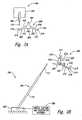
- FIG. 1is a partially schematic illustration of an aircraft recovery system 100 configured to intercept and recover an unmanned aircraft (not shown) in flight and control post-recovery motion of the aircraft in accordance with an embodiment of the disclosure.
- the aircraft recovery system 100can include, for example, a base portion 102 (shown schematically) and an elongated flexible rod or aircraft capture member 104 attached to the base portion 102.
- the flexible rod 104has a first end movably coupled to the base portion 102 via an attachment member or joint 106, and a second free end positioned to intercept the aircraft.
- the joint 106is configured to allow the flexible rod 104 to pivot (as shown in broken lines) relative to the base portion 102 before, during, and after intercepting the unmanned aircraft in flight.
- the system 100further includes an energy capture and dissipation assembly 108 (shown schematically) operably coupled to the flexible rod 104.
- the flexible rod 104When an aircraft impacts the aircraft recovery system 100, the flexible rod 104 releasably captures the aircraft and the system 100 is configured to absorb and dissipate the aircraft's landing forces and recover the aircraft. Once captured, the aircraft can be suspended from the flexible rod 104 by one of its wings or another suitable component of the aircraft, or by a capture line carried by the aircraft. Further details regarding the aircraft recovery system 100 and use of the system 100 to recover and control post-recovery motion of aircraft are described below with reference to Figures 2A-5C .
- the base portion 102can include a wide variety of different structures (e.g., generally rigid, semi-rigid, and/or inflatable) configured to support the flexible rod 104 during capture and recovery operations.
- the base portion 102is configured to (a) hold the flexible rod 104 at a desired position before capture operations (e.g., canted or angled relative to the ground and toward the aircraft), and (b) support the flexible rod 104 during capture and recovery to help prevent the aircraft and its components from hitting the ground or surrounding structures with excessive force.
- the base portion 102is configured to rest on the ground or a suitable support platform (e.g., a truck or other suitable land vehicle, a boat or other water vessel, a building, or other suitable vehicles and/or structures).
- the base portion 102can have a different arrangement and/or can be composed of different materials. Moreover, the base portion 102 may not be included in some embodiments. In such instances, the flexible rod 104 may be supported using other suitable support assemblies and/or may be a self-supporting component.
- the flexible rod 104can include a first portion 110 and a second portion 112 at a distal end of the first portion 110.
- the first and second portions 110 and 112are aligned with each other (at least initially before capture and recovery operations) and extend along a longitudinal axis of the flexible rod 104.
- the first and second portions 110 and 112are integral with each other. In other embodiments, however, the first and second portions 110 and 112 may be separate components that are fixedly or releasably attached or mated together.
- the individual portions of the flexible rod 104may be coupled together via a resilient line or cable (e.g., an elastic cord).
- the individual portions of the flexible rod 104may have a telescoping or articulating arrangement relative to each other.
- the flexible rod 104may not include separate portions, or the flexible rod 104 may include three or more discrete portions.
- the first portion 110 and the second portion 112can have a variety of different dimensions and configurations depending upon the desired operational requirements.
- the first portion 110has a first cross-sectional dimension D 1 and a first length L 1
- the second portion 112has a second cross-sectional dimension D 2 and a second length L 2 less than the first cross-sectional dimension D 1 and the first length L 1 , respectively.
- the first and second portions 110 and 112may have a different arrangement relative to each other.
- the first and second portions 110 and 112may have the same cross-sectional dimension and/or the second portion 112 may have a different length relative to the first portion 110.
- a distal portion of the flexible rod 104can be positioned at an elevation E above the local surface (e.g., the ground shown in Figure 1 ).
- the elevation Ecan vary based upon the configuration of the flexible rod 104, the configuration of the aircraft (not shown), and the local environment.
- One feature of the system 100is that the elevation E only needs to be as high as the anticipated capture elevation.
- the overall length of the flexible rod 104can be significantly less than many existing aircraft capture devices that require much greater deployment elevations.
- An advantage of this featureis that the flexible rod 104 may be easier to store and/or transport than larger, existing aircraft capture systems.
- the aircraftmay be easier to retrieve after capture because of the reduced capture elevation.
- the flexible rod 104can be composed of a carbon fiber material, a carbon graphite material, fiberglass, other composite materials (e.g., carbon/graphite or graphite/boron composites), bamboo, or another suitable material having the desired material characteristics.
- the selected materialshould have the strength and flexibility to intercept and capture an aircraft when it flies into the flexible rod 104 and, once captured, to suspend the aircraft by one of its wings or another suitable capture mechanism carried by the aircraft.
- the first portion 110has a first stiffness and the second portion 112 has a second stiffness less than the first stiffness.
- the second portion 112is accordingly more flexible than the first portion 110 and is configured to bend or flex more than the first portion 110 during operation.
- first and second portions 110 and 112may have the same or approximately the same stiffness.
- first and/or second portions 110 and 112may be composed of one or more materials having different qualities and/or characteristics than those discussed above.
- the second portion 112 of the flexible rod 104may be covered or coated with a relatively soft, rope-like material 113 or other suitable material configured to provide enhanced grip for the hook portion carried by the aircraft.
- the materialfor example, can be relatively soft, flexible sheath over a desired part of the second portion 112 or an external coating or layer applied directly onto the second portion 112 of the flexible rod 104.
- the sheath or external coatingis expected to reduce and/or inhibit slipping of the hook portion of the aircraft during capture, and is also expected to strengthen the second portion 112 and make the flexible rod 104 more resilient in tension along a longitudinal axis of the flexible rod 104.
- one or more additional parts of the flexible rod 104may include the sheath or coating.
- the first and/or second portions 110 and 112may include one or more ridges or protrusions positioned to prevent or inhibit the hook from the aircraft from slipping off the flexible rod 104.
- the sheath/coating/ridgesare optional features that may not be included in some embodiments.
- the energy capture and dissipation assembly 108can include a hydraulic damper, a pneumatic damper, plastically deforming material(s), a passive takeup reel, a brake, or other suitable damping devices configured to dissipate the aircraft's kinetic energy.
- One feature of the energy capture and dissipation assembly 108is that the assembly is expected to provide precise control of the forces associated with capture and recovery of the aircraft. Accordingly, recovery and energy management can be closely controlled throughout the capture and recovery process. This feature is expected to help inhibit and/or prevent damage to the aircraft during capture operations.
- the energy capture and dissipation assemblycan have a different configuration and/or include different features.
- the system 100does not include the energy capture and dissipation assembly 108.
- the system 100can be deployed to a desired location and configured as the primary device for capture and recovery operations.
- the system 100may be a modular system and an operator can transport the system components in a generally disassembled or partially assembled state to a landing zone and assemble the components on-site. In another embodiment, however, the system 100 may be transported to the desired landing zone in a generally assembled configuration.
- the aircraft recovery system 100is a scalable system that can be used as a primary aircraft recovery system for a variety of different aircraft configurations and/or arrangements.
- the flexible rod 104can have an overall length and cross-sectional dimension based, at least in part, on the particular dimensions of the aircraft to be recovered, the operational conditions of the aircraft, and/or the operational considerations of the system 100 (e.g., the location of the system 100, the desired transportability of the system 100, etc.).
- Figures 2A-2Fare partially schematic illustrations of the system 100 recovering an unmanned aircraft 200 in flight and controlling post-recovery motion of the aircraft 200 in accordance with an embodiment of the disclosure.
- Figures 2A and 2Bare a top view and a side view, respectively, of the aircraft 200 approaching the system 100 before capture.
- the aircraft 200can include a fuselage 201, a pair of wings or lifting surfaces 202 extending outwardly from the fuselage 201, and a propeller 204 positioned at the aft end of the fuselage 201 to propel the aircraft 200 during flight.
- the individual wings 202include a leading edge 210, a trailing edge 212, and an outboard edge 214.
- Each wing 202can also include an upwardly extending winglet 203 at the outboard edge 214 for lateral stability and control.
- the aircraft 200further includes an engagement or capture device 216 at the outboard edge 214 of each wing 202.
- the engagement device 216may have a different configuration and/or may be positioned at another suitable location on the aircraft 200.
- the aircraft 200may include a different number of engagement devices 216.
- the flexible rod 104is angled or canted toward the aircraft 200.
- One advantage of this arrangementis that it can provide a larger range of movement for the flexible rod 104 after capture of the aircraft 200.
- the flexible rod 104may have a generally vertical arrangement or another arrangement relative to the aircraft's local flight path and the local surface (e.g., the ground shown in Figure 2B ).
- the aircraft 200intercepts the free end of the flexible rod 104 and the second portion 112 of the flexible rod 104 and the leading edge 210 of one of the wings 202 slide relative to each other toward the corresponding engagement device 216.
- the engagement device 216 at the outboard edge 214 of the wing 202receives and retains part of the second portion 112 of the flexible rod 104, thus causing the aircraft 200 to begin to yaw or rotate toward the flexible rod 104.
- the force of impact with the aircraft 200also causes the flexible rod 104 to pivot or move relative to the base portion 102.
- the flexible rod 104has moved from its initial angled or canted arrangement to a generally vertical position.
- the second portion 112 of the flexible rod 104has begun to flex or bend in response to the aircraft's momentum. It will also be appreciated that the first portion 110 of the flexible rod 104 may also flex or bend during capture operations. Moreover, in some embodiments the base 102 may also be configured to move or articulate in a predetermined manner to help absorb the energy of impact.
- the recovery processcontinues with the flexible rod 104 continuing to pivot or move relative to the base portion 102 in response to the aircraft's momentum.
- the flexible rod 104has moved past the generally vertical arrangement and is now angled or canted away from the aircraft's incoming flight path.
- the second portion 112continues to flex or bend in response to the landing forces from the aircraft 200.
- the forcesare transferred from the aircraft 200 to the flexible rod 104 and, in turn, to the energy capture and dissipation assembly 108. In this way, the system 100 can absorb a significant amount of the aircraft's landing forces.
- the delicate componentse.g., turret, pitot tubes, etc.
- the delicate componentse.g., turret, pitot tubes, etc.
- the aircraft 200has come to a complete or approximately complete stop and remains secured to the flexible rod 104.
- the assembly 108is configured to provide precise control of the forces associated with capture and recovery of the aircraft 200, and help inhibit, reduce, and/or eliminate damage to the aircraft 200 during capture operations.
- the aircraft 200is suspended above the ground and away from other external structures after capture, and can be quickly and easily retrieved from the flexible rod 104 by ground personnel (not shown).
- the system 100can be quickly deployed and configured for landing operations in a variety of different environments and operational conditions.
- Many conventional recovery systemsfor example, require elaborate and complex components that are relatively immobile and require a significant amount time and expense to deploy.
- the system 100is a modular system that can be easily transported in a partially assembled or disassembled state to a wide variety of different operational environments, and quickly assembled and deployed for landing operations with minimal manpower.
- the system 100has a much smaller footprint than many conventional systems, the system 100 can be used in a wide variety of different operational environments and conditions where use of many conventional systems may be impracticable.
- the aircraft 200can be quickly recovered from the system 100 after landing operations and prepared for storage and/or another mission.
- Another feature of embodiments of the system 100 described aboveis that they can be used to recover aircraft having a variety of different configurations in addition to the aircraft 200 described above with reference to Figures 2A-2F .
- One advantage of this featureis that the system 100 can be used with existing fleets of unmanned aircraft without requiring expensive and/or time-consuming modifications to such aircraft.
- a single system 100may be deployed and used for landing operations in a particular area or region for an entire fleet of different unmanned aircraft.
- Figures 3A-3Gare partially schematic illustrations of the system 100 recovering an unmanned aircraft 300 in flight and controlling post-recovery motion of the aircraft 300 in accordance with another embodiment of the disclosure.
- Figures 3A and 3Bare a top view and a side view, respectively, of the aircraft 300 approaching the system 100 before capture.
- the methods described below with reference to Figures 3A-3Gdiffer from the techniques described above in that the aircraft 300 has a different configuration than the aircraft 200. More specifically, rather than intercepting the flexible rod 104 with a wing of the aircraft as described above with reference to Figures 2A-2D , the aircraft 300 includes a capture assembly 320 configured to engage or hook onto a portion of the flexible rod 104 and capture the aircraft 300.
- the capture assembly 320can include, for example, one or more deployable flexible support lines 322 (e.g., ropes or cables) attached to each wing 202 and positioned to engage the free end of the flexible rod 104.
- the support line 322is attached to a top portion of each wing 202 at least proximate to a lateral axis through a center of gravity (CG) of the aircraft 300.
- CGcenter of gravity
- attaching the support line 322 along the lateral axis through the CG of the aircraft 300can cause the aircraft 300 to pitch up during recovery and can help provide additional deceleration during such operations.
- the capture assembly 320can also include an engagement feature 324 (e.g., a hook, etc.) carried by the flexible rod 104 and positioned to releasably engage the support line 322.
- the engagement feature 324can include different features and/or have a different arrangement.
- the support line 322may also include weights or other aerodynamic features (not shown) to help the support line 322 maintain proper shape and position in flight relative to the aircraft 300 and the engagement feature 324.
- the capture assembly 320is that the support line 322 is attached to each wing 202 at natural strong points of the wings 202. Such points are already designed to withstand significant loads and, accordingly, additional wing and/or fuselage support structures are not expected to be necessary to withstand the forces associated with capture and recovery of the aircraft 300. Moreover, the aircraft's control surfaces and other fragile portions of the aircraft 300 experience few or no stresses during capture operations.
- the support line 322intercepts and engages the second portion 112 of the flexible rod 104.
- the engagement feature 324receives and retains part of the support line 322, thus securing the aircraft 300 to the flexible rod 104.
- the aircraft 300begins to pitch up and decelerate after capture, thereby moving the flexible rod 104 from its initial angled or canted arrangement to a generally vertical position.
- the support line 322is anchored at least proximate to a lateral axis through a CG of the aircraft 300.
- the momentum of the aircraft 300causes the aircraft 300 to pitch up to a generally nose-high attitude and hold in a deep stall.
- One advantage of this featureis that it allows the support line 322 to quickly induce aerodynamic decelerations forces on the aircraft 300, while initially producing upward momentum of the aircraft 300. This feature is expected to help quickly decelerate the aircraft 300 and reduce or minimize the possibility of the aircraft 300 contacting the ground or other external structure during capture operations.
- the recovery processcontinues with the flexible rod 104 continuing to pivot or move relative to the base portion 102 in response to the aircraft's momentum.
- the flexible rod 104for example, is now angled or canted away from the aircraft's incoming flight path.
- the second portion 112continues to flex or bend in response to the landing forces from the aircraft 300.
- the aircraft 300rapidly decelerates, the forces from the aircraft 300 are transferred to the flexible rod 104 and the energy capture and dissipation assembly 108.
- the aircraft 300has come to a complete or approximately complete stop and remains secured to the flexible rod 104 via the support line 322.
- the length of the support line 322can be selected such that the aircraft 300 remains suspended above and out of contact with the ground or other external structure after capture.
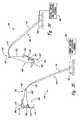
- Figures 4A-4Dare partially schematic illustrations of a system 400 configured to recover an unmanned aircraft (e.g., the aircraft 200 or aircraft 300 discussed above) in flight and control post-recovery motion of the aircraft in accordance with still another embodiment of the disclosure.
- the aircraft recovery system 400can include several features generally similar to the system 100 described above with reference to Figure 1 .
- the system 400can include, for example, a base portion 402 and an elongated flexible rod or aircraft capture member 404 attached to the base portion 402.
- the flexible rod 404can include a first portion 410 and a second portion 412 at a distal end of the first portion 410.
- the second portion 412is an elongated wire attached to an end of the first portion 410.
- first portion 410 and/or second portion 412may be composed of different material(s) and/or have a different arrangement.
- the flexible rod 404may not include separate portions, or the flexible rod 404 may include three or more discrete portions.
- At least one of the first and second portions 410 and 412is operably coupled to a tension line or takeup line 414 (shown and described below with reference to Figure 4B ).
- the tension line 414is attached to the second portion 412 of the flexible rod 404.
- the system 400also includes a tension reel 408 operably coupled to the tension line 414 and configured to wind/unwind the tension line 414 during operation.
- the tension reel 408is carried by the base portion 402 and positioned to wind/unwind the tension line 414.
- the tension reel 408can have a different arrangement relative to the other components in the system 400 and/or may include different features.
- the tension reel 408may be positioned at a variety of different locations relative to the base portion 402 and/or the flexible rod 404.
- the aircraft 200intercepts the flexible rod 404, and the second portion 412 of the flexible rod 404 and the leading edge 210 of one of the wings 202 slide relative to each other toward the corresponding engagement device 216.
- the aircraft 200begins to yaw or rotate about the flexible rod 404.
- the force of impact with the aircraft 200also causes the entire flexible rod 404 (both the first and second portions 410 and 412) to bend or bow.
- any slack in the tension line 414is taken up by the tension reel 408.
- the second portion 412may be at least partially extendable in response to the momentum of the aircraft 200. In one embodiment, for example, the second portion 412 can extend or spool out relative to the first portion 410 a selected distance after impact of the aircraft 200.
- the flexible rod 404has moved from its initial, generally vertical arrangement to an angled or canted arrangement as the aircraft 200 continues to yaw or pivot about the flexible rod 404. Moreover, the flexible rod 404 continues to flex or bend in response to the forces from the aircraft 200. Referring to Figure 4D , the aircraft 200 has come to a complete or approximately complete stop and remains secured to the flexible rod 404. The tension line 414 remains generally taut, which can help keep the aircraft 200 suspended above the ground and away from other external structures after capture. In this arrangement, the aircraft 200 can be quickly and easily retrieved from the flexible rod 404 by ground personnel (not shown).
- an aircraftcan include generally unswept wings.
- an aircraftcan include delta wings.
- the aircraftcan have propulsion systems that are different than and/or arranged differently than those described above with reference to Figures 1-4D .
- the aircraftcan remain compatible with some or all of the systems and methods above for capturing and controlling post-capture motion of the aircraft.
- Figures 5A-5Billustrate elongated aircraft capture members and aircraft recovery systems configured in accordance with other embodiments the disclosure.
- the aircraft capture members and systems of Figures 5A-5Bcan be used with the aircraft, systems, and methods described above with reference to Figures 1-4D .
- the aircraft capture members and recovery systems described belowcan include many of the same features and advantages of the systems and methods described above.
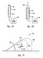
- FIG. 5Ais a partially schematic illustration of a distal portion of an elongated flexible rod or aircraft capture member 502 configured in accordance with another embodiment of the disclosure.
- the aircraft capture member 502includes an inner inflatable portion 504 and an outer engagement portion or sheath 506 at least partially covering the inner inflatable portion 504.
- the inflatable portion 504can include one or more bladders filled to a desired pressure with a gas (e.g., air) using a gas source 508.
- the pressurized aircraft capture member 502can accordingly extend in a generally vertical or angled/canted configuration (e.g., similar to the elongated flexible rods or aircraft capture members described above).
- the outer sheath 506can be composed of a relatively soft, rope-like material or other suitable material configured to provide better grip for a hook portion carried by the aircraft.
- the outer sheath 506is configured to directly engage the aircraft (not shown) during capture operations, as well as protect the inner inflatable portion 504 from damage and/or puncture.
- the aircraft capture member 502has an initially deflated, non-rigid arrangement (e.g., a deflated balloon). After energizing the gas source 508 and inflating the inner inflatable portion 504 to a desired pressue, the aircraft capture member 502 has a configuration generally similar to the arrangement of the flexible rod 104 of Figure 1 , and can be positioned at a desired orientation (e.g., generally vertical or canted relative to the ground and the aircraft to be captured. In several embodiments, one or more flexible lines, capture devices, and/or engagement members can be carried by or coupled to the aircraft capture member 502 and positioned to releasably engage the aircraft during capture and recovery operations.
- a desired orientatione.g., generally vertical or canted relative to the ground and the aircraft to be captured.
- one or more flexible lines, capture devices, and/or engagement memberscan be carried by or coupled to the aircraft capture member 502 and positioned to releasably engage the aircraft during capture and recovery operations.
- Figure 5Bis a partially schematic illustration of still another embodiment of an aircraft capture member 520 configured in accordance with an embodiment of the disclosure.
- the aircraft capture member 520includes an inner tubing or bladder 522 operably coupled to a gas source 530, and an outer engagement portion or sheath 524 at least partially covering the inner tubing 522.
- the aircraft capture member 520further includes a thruster 526 coupled to the inner tubing 522 and outer sheath 524.
- the inner tubing 522 and outer sheath 524are arranged relative to each other in a telescoping arrangement.
- the thruster 526can be activated (e.g., using the gas source 530) and can pull up or extend the outer sheath 524 to a desired elevation above the local surface (e.g., ground) as the thruster 526 is launched away from its initial position.
- the aircraft capture member 520can have an elongated, generally vertical arrangement (e.g., similar to the flexible rod 104 of Figure 1 ) positioned to intercept an aircraft in flight for capture and recovery operations.
- FIG. 5Cis a partially schematic illustration of an aircraft recovery system 540 not in accordance with the present invention.
- the system 540includes an elongated flexible rod or aircraft capture member 542 having a first portion 544 and one or more second portions 546 (two are shown in broken lines as 546a and 546b) positioned to intercept an unmanned aircraft in flight. It will be appreciated that the system 540 may include only a single second portion 546, or may include more than two second portions 546 extending from the first portion 542.
- the second portions 546can have material characteristics and features generally similar to the second portions 112/412 described above.
- the system 540differs from the systems described above in that rather than having an elongated rod or aircraft recovery member with an initial, generally linear and generally vertical arrangement, the second portions 546a and 546b of the system 540 are initially curved or non-linear. Moreover, each of the second portions 546a and 546b has a first end attached to the first portion 544 of the aircraft capture member 542 and a second end attached to the local surface (e.g., the ground) or another suitable structure. In several embodiments, the second ends of the individual second portions 546 may be configured to break free or become detached when the tension in the respective line exceeds a threshold value. In still other embodiments, the second ends of the individual second portions 546 may remain free rather than being attached to the local surface or another structure. After capture and recovery operations, the second portions 546 can reach a final state or arrangement (as shown by line 547) and the aircraft 200 can be retrieved from the line.
- the flexible rods described abovecan have a telescoping arrangement with the second portions (and any additional portions) of the individual rods at least partially received within the first portions in a stowed configuration before or after operation.
- any of the flexible rods described abovecan include one or more engagement members (e.g., hooks, loops, multiple loops, etc.) at or near the top portion of the flexible rod and positioned to engage the aircraft directly and/or engage a capture assembly carried by the aircraft.
- the aircraft capture members described abovehave a generally upward, vertical orientation, the flexible rods may also be suspended from a suitable support structure in a generally downward orientation for capture and recovery operations.
Landscapes
- Engineering & Computer Science (AREA)
- Aviation & Aerospace Engineering (AREA)
- Mechanical Engineering (AREA)
- Remote Sensing (AREA)
- Tires In General (AREA)
- Toys (AREA)
- Control Of Position, Course, Altitude, Or Attitude Of Moving Bodies (AREA)
- Catching Or Destruction (AREA)
- Manipulator (AREA)
- Transmission Devices (AREA)
Description
- The present disclosure relates generally to systems and methods for recovering unmanned aircraft and controlling post-recovery motion of the aircraft.
- Unmanned aircraft or air vehicles (UAVs) provide enhanced and economical access to areas where manned flight operations are unacceptably costly and/or dangerous. For example, unmanned aircraft outfitted with remotely operated movable cameras can perform a wide variety of surveillance missions, including spotting schools of fish for the fisheries industry, monitoring weather conditions, providing border patrols for national governments, and providing military surveillance before, during, and/or after military operations.
- Many unmanned aircraft systems (which can include the aircraft itself along with launch devices and recovery devices), however, can be difficult to install and operate in cramped quarters, such as the deck of a small fishing boat, land vehicle, or other craft. Accordingly, operating such aircraft systems often includes retrieving or capturing the aircraft with a flexible recovery line when space is insufficient for a normal landing run. While this technique has proven successful in many instances, there is a continual need to improve the effectiveness of systems with which aircraft are recovered.
WO 2008/015663 A1 refers to a launching and landing system for unmanned aircraft which is built up as a slingshot structure. It is the technical disadvantage that the slingshot structure requires a relatively large space at the place of installation, and therefore might be restricted to few sites of usage.GB 2,231,011 A GB 2,093,414 A US 2006/0249623 A1 refers to a robotically assisted launch and capture platform for an unmanned aircraft. However, the robot arm is expensive to produce and install on the operation site.- Therefore it is the technical object of the present invention to provide an aircraft recovery system and to provide a method for recovering unmanned aircrafts, wherein such system and method can be installed and operated on different sites of operation, especially in cramped quarters, such as on deck of a small fishing boat, land vehicle, or other craft.
- This object can be solved with the features of claim 1, independent claim 7, or independent method claim 12.
- Further improved embodiments of the present invention are provided by the dependent claims.
Figure 1 is a partially schematic illustration of a system configured to recover an unmanned aircraft in flight and control post-recovery motion of the aircraft in accordance with an embodiment of the disclosure.Figures 2A-2F are partially schematic illustrations of a system and method for recovering an unmanned aircraft in flight and controlling post-recovery motion of the aircraft in accordance with an embodiment of the disclosure.Figures 3A-3F are partially schematic illustrations of a system and method for recovering an unmanned aircraft in flight and controlling post-recovery motion of the aircraft in accordance with another embodiment of the disclosure.Figures 4A-4D are partially schematic illustrations of a system and method for recovering an unmanned aircraft in flight and controlling post-recovery motion of the aircraft in accordance with still another embodiment of the disclosure.Figure 5A is a partially schematic illustration of a distal portion of an aircraft capture member configured in accordance with another embodiment of the disclosure.Figure 5B is a partially schematic illustration of still another embodiment of an aircraft capture member configured in accordance with an embodiment of the disclosure.Figure 5C is a partially schematic illustration of an aircraft recovery system not in accordance with the present invention.- The present disclosure describes systems and methods for recovering unmanned aircraft and controlling post-recovery motion of the aircraft. Many specific details of certain embodiments of the disclosure are set forth in the following description and in
Figures 1-5B to provide a thorough understanding of these embodiments. Well-known structures, systems, and methods often associated with such systems have not been shown or described in detail to avoid unnecessarily obscuring the description of the various embodiments of the disclosure. In addition, those of ordinary skill in the relevant art will understand that additional embodiments may be practiced without several of the details described below. Figure 1 is a partially schematic illustration of anaircraft recovery system 100 configured to intercept and recover an unmanned aircraft (not shown) in flight and control post-recovery motion of the aircraft in accordance with an embodiment of the disclosure. Theaircraft recovery system 100 can include, for example, a base portion 102 (shown schematically) and an elongated flexible rod oraircraft capture member 104 attached to thebase portion 102. In the illustrated embodiment, theflexible rod 104 has a first end movably coupled to thebase portion 102 via an attachment member orjoint 106, and a second free end positioned to intercept the aircraft. Thejoint 106 is configured to allow theflexible rod 104 to pivot (as shown in broken lines) relative to thebase portion 102 before, during, and after intercepting the unmanned aircraft in flight. Thesystem 100 further includes an energy capture and dissipation assembly 108 (shown schematically) operably coupled to theflexible rod 104. When an aircraft impacts theaircraft recovery system 100, theflexible rod 104 releasably captures the aircraft and thesystem 100 is configured to absorb and dissipate the aircraft's landing forces and recover the aircraft. Once captured, the aircraft can be suspended from theflexible rod 104 by one of its wings or another suitable component of the aircraft, or by a capture line carried by the aircraft. Further details regarding theaircraft recovery system 100 and use of thesystem 100 to recover and control post-recovery motion of aircraft are described below with reference toFigures 2A-5C .- The
base portion 102 can include a wide variety of different structures (e.g., generally rigid, semi-rigid, and/or inflatable) configured to support theflexible rod 104 during capture and recovery operations. In general, thebase portion 102 is configured to (a) hold theflexible rod 104 at a desired position before capture operations (e.g., canted or angled relative to the ground and toward the aircraft), and (b) support theflexible rod 104 during capture and recovery to help prevent the aircraft and its components from hitting the ground or surrounding structures with excessive force. Thebase portion 102 is configured to rest on the ground or a suitable support platform (e.g., a truck or other suitable land vehicle, a boat or other water vessel, a building, or other suitable vehicles and/or structures). In other embodiments, thebase portion 102 can have a different arrangement and/or can be composed of different materials. Moreover, thebase portion 102 may not be included in some embodiments. In such instances, theflexible rod 104 may be supported using other suitable support assemblies and/or may be a self-supporting component. - The
flexible rod 104 can include afirst portion 110 and asecond portion 112 at a distal end of thefirst portion 110. The first andsecond portions flexible rod 104. In the illustrated embodiment, the first andsecond portions second portions flexible rod 104 may be coupled together via a resilient line or cable (e.g., an elastic cord). Moreover, the individual portions of theflexible rod 104 may have a telescoping or articulating arrangement relative to each other. In still other embodiments, theflexible rod 104 may not include separate portions, or theflexible rod 104 may include three or more discrete portions. - The
first portion 110 and thesecond portion 112 can have a variety of different dimensions and configurations depending upon the desired operational requirements. In the illustrated embodiment, for example, thefirst portion 110 has a first cross-sectional dimension D1 and a first length L1, and thesecond portion 112 has a second cross-sectional dimension D2 and a second length L2 less than the first cross-sectional dimension D1 and the first length L1, respectively. In other embodiments, however, the first andsecond portions second portions second portion 112 may have a different length relative to thefirst portion 110. - In another aspect of this embodiment, a distal portion of the
flexible rod 104 can be positioned at an elevation E above the local surface (e.g., the ground shown inFigure 1 ). The elevation E can vary based upon the configuration of theflexible rod 104, the configuration of the aircraft (not shown), and the local environment. One feature of thesystem 100 is that the elevation E only needs to be as high as the anticipated capture elevation. Thus, the overall length of theflexible rod 104 can be significantly less than many existing aircraft capture devices that require much greater deployment elevations. An advantage of this feature is that theflexible rod 104 may be easier to store and/or transport than larger, existing aircraft capture systems. Moreover, the aircraft may be easier to retrieve after capture because of the reduced capture elevation. - The
flexible rod 104 can be composed of a carbon fiber material, a carbon graphite material, fiberglass, other composite materials (e.g., carbon/graphite or graphite/boron composites), bamboo, or another suitable material having the desired material characteristics. The selected material, for example, should have the strength and flexibility to intercept and capture an aircraft when it flies into theflexible rod 104 and, once captured, to suspend the aircraft by one of its wings or another suitable capture mechanism carried by the aircraft. In one particular aspect of this embodiment, thefirst portion 110 has a first stiffness and thesecond portion 112 has a second stiffness less than the first stiffness. Thesecond portion 112 is accordingly more flexible than thefirst portion 110 and is configured to bend or flex more than thefirst portion 110 during operation. Further details regarding this feature are described below with reference toFigures 2A-2F . In other embodiments, however, the first andsecond portions second portions - In several embodiments, at least part of the
second portion 112 of theflexible rod 104 may be covered or coated with a relatively soft, rope-like material 113 or other suitable material configured to provide enhanced grip for the hook portion carried by the aircraft. The material, for example, can be relatively soft, flexible sheath over a desired part of thesecond portion 112 or an external coating or layer applied directly onto thesecond portion 112 of theflexible rod 104. The sheath or external coating is expected to reduce and/or inhibit slipping of the hook portion of the aircraft during capture, and is also expected to strengthen thesecond portion 112 and make theflexible rod 104 more resilient in tension along a longitudinal axis of theflexible rod 104. In other embodiments, one or more additional parts of the flexible rod 104 (e.g., at least part of the first portion 110) may include the sheath or coating. In still other embodiments, the first and/orsecond portions flexible rod 104. The sheath/coating/ridges, however, are optional features that may not be included in some embodiments. - The energy capture and
dissipation assembly 108 can include a hydraulic damper, a pneumatic damper, plastically deforming material(s), a passive takeup reel, a brake, or other suitable damping devices configured to dissipate the aircraft's kinetic energy. One feature of the energy capture anddissipation assembly 108 is that the assembly is expected to provide precise control of the forces associated with capture and recovery of the aircraft. Accordingly, recovery and energy management can be closely controlled throughout the capture and recovery process. This feature is expected to help inhibit and/or prevent damage to the aircraft during capture operations. In other embodiments, the energy capture and dissipation assembly can have a different configuration and/or include different features. In still other embodiments, thesystem 100 does not include the energy capture anddissipation assembly 108. - In operation, the
system 100 can be deployed to a desired location and configured as the primary device for capture and recovery operations. Thesystem 100, for example, may be a modular system and an operator can transport the system components in a generally disassembled or partially assembled state to a landing zone and assemble the components on-site. In another embodiment, however, thesystem 100 may be transported to the desired landing zone in a generally assembled configuration. - The
aircraft recovery system 100 is a scalable system that can be used as a primary aircraft recovery system for a variety of different aircraft configurations and/or arrangements. For example, as mentioned above, theflexible rod 104 can have an overall length and cross-sectional dimension based, at least in part, on the particular dimensions of the aircraft to be recovered, the operational conditions of the aircraft, and/or the operational considerations of the system 100 (e.g., the location of thesystem 100, the desired transportability of thesystem 100, etc.). Figures 2A-2F are partially schematic illustrations of thesystem 100 recovering anunmanned aircraft 200 in flight and controlling post-recovery motion of theaircraft 200 in accordance with an embodiment of the disclosure.Figures 2A and 2B , for example, are a top view and a side view, respectively, of theaircraft 200 approaching thesystem 100 before capture. Theaircraft 200 can include afuselage 201, a pair of wings or liftingsurfaces 202 extending outwardly from thefuselage 201, and apropeller 204 positioned at the aft end of thefuselage 201 to propel theaircraft 200 during flight. Theindividual wings 202 include aleading edge 210, a trailingedge 212, and anoutboard edge 214. Eachwing 202 can also include an upwardly extending winglet 203 at theoutboard edge 214 for lateral stability and control. Theaircraft 200 further includes an engagement orcapture device 216 at theoutboard edge 214 of eachwing 202. In other embodiments, theengagement device 216 may have a different configuration and/or may be positioned at another suitable location on theaircraft 200. In addition, theaircraft 200 may include a different number ofengagement devices 216.- In this embodiment, the
flexible rod 104 is angled or canted toward theaircraft 200. One advantage of this arrangement is that it can provide a larger range of movement for theflexible rod 104 after capture of theaircraft 200. In other embodiments, however, theflexible rod 104 may have a generally vertical arrangement or another arrangement relative to the aircraft's local flight path and the local surface (e.g., the ground shown inFigure 2B ). - Referring next to
Figure 2C , theaircraft 200 intercepts the free end of theflexible rod 104 and thesecond portion 112 of theflexible rod 104 and theleading edge 210 of one of thewings 202 slide relative to each other toward thecorresponding engagement device 216. Referring now toFigure 2D , theengagement device 216 at theoutboard edge 214 of thewing 202 receives and retains part of thesecond portion 112 of theflexible rod 104, thus causing theaircraft 200 to begin to yaw or rotate toward theflexible rod 104. The force of impact with theaircraft 200 also causes theflexible rod 104 to pivot or move relative to thebase portion 102. InFigure 2D , for example, theflexible rod 104 has moved from its initial angled or canted arrangement to a generally vertical position. Moreover, thesecond portion 112 of theflexible rod 104 has begun to flex or bend in response to the aircraft's momentum. It will also be appreciated that thefirst portion 110 of theflexible rod 104 may also flex or bend during capture operations. Moreover, in some embodiments thebase 102 may also be configured to move or articulate in a predetermined manner to help absorb the energy of impact. - Referring now to
Figure 2E , the recovery process continues with theflexible rod 104 continuing to pivot or move relative to thebase portion 102 in response to the aircraft's momentum. InFigure 2E , for example, theflexible rod 104 has moved past the generally vertical arrangement and is now angled or canted away from the aircraft's incoming flight path. Thesecond portion 112 continues to flex or bend in response to the landing forces from theaircraft 200. As theaircraft 200 rapidly decelerates, the forces are transferred from theaircraft 200 to theflexible rod 104 and, in turn, to the energy capture anddissipation assembly 108. In this way, thesystem 100 can absorb a significant amount of the aircraft's landing forces. Moreover, because the stresses on theaircraft 200 during capture operations are primarily exerted on the wing structures during impact, the delicate components (e.g., turret, pitot tubes, etc.) at a nose portion of theaircraft 200 and the other fragile portions of theaircraft 200 experience few or no stresses during capture and recovery operations. - Referring to
Figure 2F , theaircraft 200 has come to a complete or approximately complete stop and remains secured to theflexible rod 104. As mentioned previously, theassembly 108 is configured to provide precise control of the forces associated with capture and recovery of theaircraft 200, and help inhibit, reduce, and/or eliminate damage to theaircraft 200 during capture operations. In the illustrated embodiment, for example, theaircraft 200 is suspended above the ground and away from other external structures after capture, and can be quickly and easily retrieved from theflexible rod 104 by ground personnel (not shown). - One feature of embodiments of the
system 100 and methods described above with reference toFigures 1-2F is that thesystem 100 can be quickly deployed and configured for landing operations in a variety of different environments and operational conditions. Many conventional recovery systems, for example, require elaborate and complex components that are relatively immobile and require a significant amount time and expense to deploy. In contrast with such conventional systems, thesystem 100 is a modular system that can be easily transported in a partially assembled or disassembled state to a wide variety of different operational environments, and quickly assembled and deployed for landing operations with minimal manpower. In addition, because thesystem 100 has a much smaller footprint than many conventional systems, thesystem 100 can be used in a wide variety of different operational environments and conditions where use of many conventional systems may be impracticable. Moreover, theaircraft 200 can be quickly recovered from thesystem 100 after landing operations and prepared for storage and/or another mission. - Another feature of embodiments of the
system 100 described above is that they can be used to recover aircraft having a variety of different configurations in addition to theaircraft 200 described above with reference toFigures 2A-2F . One advantage of this feature is that thesystem 100 can be used with existing fleets of unmanned aircraft without requiring expensive and/or time-consuming modifications to such aircraft. Furthermore, because thesystem 100 can be used with a variety of different aircraft, asingle system 100 may be deployed and used for landing operations in a particular area or region for an entire fleet of different unmanned aircraft. Figures 3A-3G are partially schematic illustrations of thesystem 100 recovering anunmanned aircraft 300 in flight and controlling post-recovery motion of theaircraft 300 in accordance with another embodiment of the disclosure.Figures 3A and 3B , for example, are a top view and a side view, respectively, of theaircraft 300 approaching thesystem 100 before capture. The methods described below with reference toFigures 3A-3G differ from the techniques described above in that theaircraft 300 has a different configuration than theaircraft 200. More specifically, rather than intercepting theflexible rod 104 with a wing of the aircraft as described above with reference toFigures 2A-2D , theaircraft 300 includes acapture assembly 320 configured to engage or hook onto a portion of theflexible rod 104 and capture theaircraft 300.- The
capture assembly 320 can include, for example, one or more deployable flexible support lines 322 (e.g., ropes or cables) attached to eachwing 202 and positioned to engage the free end of theflexible rod 104. In the illustrated embodiment, thesupport line 322 is attached to a top portion of eachwing 202 at least proximate to a lateral axis through a center of gravity (CG) of theaircraft 300. As discussed in greater detail below, attaching thesupport line 322 along the lateral axis through the CG of theaircraft 300 can cause theaircraft 300 to pitch up during recovery and can help provide additional deceleration during such operations. Thecapture assembly 320 can also include an engagement feature 324 (e.g., a hook, etc.) carried by theflexible rod 104 and positioned to releasably engage thesupport line 322. In other embodiments, theengagement feature 324 can include different features and/or have a different arrangement. In at least some embodiments, thesupport line 322 may also include weights or other aerodynamic features (not shown) to help thesupport line 322 maintain proper shape and position in flight relative to theaircraft 300 and theengagement feature 324. - One feature of the
capture assembly 320 is that thesupport line 322 is attached to eachwing 202 at natural strong points of thewings 202. Such points are already designed to withstand significant loads and, accordingly, additional wing and/or fuselage support structures are not expected to be necessary to withstand the forces associated with capture and recovery of theaircraft 300. Moreover, the aircraft's control surfaces and other fragile portions of theaircraft 300 experience few or no stresses during capture operations. - Referring next to
Figure 3C , thesupport line 322 intercepts and engages thesecond portion 112 of theflexible rod 104. Theengagement feature 324 receives and retains part of thesupport line 322, thus securing theaircraft 300 to theflexible rod 104. Referring now toFigure 3D , theaircraft 300 begins to pitch up and decelerate after capture, thereby moving theflexible rod 104 from its initial angled or canted arrangement to a generally vertical position. As mentioned above, thesupport line 322 is anchored at least proximate to a lateral axis through a CG of theaircraft 300. Accordingly, after capture of thesupport line 322 by theflexible rod 104, the momentum of theaircraft 300 causes theaircraft 300 to pitch up to a generally nose-high attitude and hold in a deep stall. One advantage of this feature is that it allows thesupport line 322 to quickly induce aerodynamic decelerations forces on theaircraft 300, while initially producing upward momentum of theaircraft 300. This feature is expected to help quickly decelerate theaircraft 300 and reduce or minimize the possibility of theaircraft 300 contacting the ground or other external structure during capture operations. - Referring now to
Figure 3E , the recovery process continues with theflexible rod 104 continuing to pivot or move relative to thebase portion 102 in response to the aircraft's momentum. Theflexible rod 104, for example, is now angled or canted away from the aircraft's incoming flight path. Thesecond portion 112 continues to flex or bend in response to the landing forces from theaircraft 300. As theaircraft 300 rapidly decelerates, the forces from theaircraft 300 are transferred to theflexible rod 104 and the energy capture anddissipation assembly 108. Referring toFigure 3F , theaircraft 300 has come to a complete or approximately complete stop and remains secured to theflexible rod 104 via thesupport line 322. The length of thesupport line 322 can be selected such that theaircraft 300 remains suspended above and out of contact with the ground or other external structure after capture. Figures 4A-4D are partially schematic illustrations of asystem 400 configured to recover an unmanned aircraft (e.g., theaircraft 200 oraircraft 300 discussed above) in flight and control post-recovery motion of the aircraft in accordance with still another embodiment of the disclosure. Theaircraft recovery system 400 can include several features generally similar to thesystem 100 described above with reference toFigure 1 . Thesystem 400 can include, for example, abase portion 402 and an elongated flexible rod oraircraft capture member 404 attached to thebase portion 402. Theflexible rod 404 can include afirst portion 410 and asecond portion 412 at a distal end of thefirst portion 410. In the illustrated embodiment, thesecond portion 412 is an elongated wire attached to an end of thefirst portion 410. In other embodiments, however, thefirst portion 410 and/orsecond portion 412 may be composed of different material(s) and/or have a different arrangement. For example, in some embodiments theflexible rod 404 may not include separate portions, or theflexible rod 404 may include three or more discrete portions.- At least one of the first and
second portions Figure 4B ). In the illustrated embodiment, for example, thetension line 414 is attached to thesecond portion 412 of theflexible rod 404. Thesystem 400 also includes atension reel 408 operably coupled to thetension line 414 and configured to wind/unwind thetension line 414 during operation. In the illustrated embodiment, thetension reel 408 is carried by thebase portion 402 and positioned to wind/unwind thetension line 414. In other embodiments, however, thetension reel 408 can have a different arrangement relative to the other components in thesystem 400 and/or may include different features. For example, thetension reel 408 may be positioned at a variety of different locations relative to thebase portion 402 and/or theflexible rod 404. - Referring next to
Figure 4B , theaircraft 200 intercepts theflexible rod 404, and thesecond portion 412 of theflexible rod 404 and theleading edge 210 of one of thewings 202 slide relative to each other toward thecorresponding engagement device 216. After theengagement device 216 at theoutboard edge 214 of thewing 202 receives and retains part of thesecond portion 412, theaircraft 200 begins to yaw or rotate about theflexible rod 404. The force of impact with theaircraft 200 also causes the entire flexible rod 404 (both the first andsecond portions 410 and 412) to bend or bow. As theflexible rod 404 bends, any slack in thetension line 414 is taken up by thetension reel 408. Keeping thetension line 414 relatively taut can help keep theflexible rod 404 in a flexed or bent configuration, and help transfer the momentum and capture forces from theaircraft 200 to thesystem 400. In other embodiments, thesecond portion 412 may be at least partially extendable in response to the momentum of theaircraft 200. In one embodiment, for example, thesecond portion 412 can extend or spool out relative to the first portion 410 a selected distance after impact of theaircraft 200. - Referring now to
Figure 4C , theflexible rod 404 has moved from its initial, generally vertical arrangement to an angled or canted arrangement as theaircraft 200 continues to yaw or pivot about theflexible rod 404. Moreover, theflexible rod 404 continues to flex or bend in response to the forces from theaircraft 200. Referring toFigure 4D , theaircraft 200 has come to a complete or approximately complete stop and remains secured to theflexible rod 404. Thetension line 414 remains generally taut, which can help keep theaircraft 200 suspended above the ground and away from other external structures after capture. In this arrangement, theaircraft 200 can be quickly and easily retrieved from theflexible rod 404 by ground personnel (not shown). - In other embodiments, the systems and methods described above with reference to
Figures 1-4D can be used in conjunction with aircraft having configurations different than those of theaircraft 200/300 described above. For example, in one embodiment an aircraft can include generally unswept wings. In another embodiment, an aircraft can include delta wings. Further, the aircraft can have propulsion systems that are different than and/or arranged differently than those described above with reference toFigures 1-4D . In any of these further embodiments, the aircraft can remain compatible with some or all of the systems and methods above for capturing and controlling post-capture motion of the aircraft. Figures 5A-5B illustrate elongated aircraft capture members and aircraft recovery systems configured in accordance with other embodiments the disclosure. The aircraft capture members and systems ofFigures 5A-5B can be used with the aircraft, systems, and methods described above with reference toFigures 1-4D . In addition, the aircraft capture members and recovery systems described below can include many of the same features and advantages of the systems and methods described above.Figure 5A , for example, is a partially schematic illustration of a distal portion of an elongated flexible rod oraircraft capture member 502 configured in accordance with another embodiment of the disclosure. Theaircraft capture member 502 includes an innerinflatable portion 504 and an outer engagement portion orsheath 506 at least partially covering the innerinflatable portion 504. Theinflatable portion 504 can include one or more bladders filled to a desired pressure with a gas (e.g., air) using agas source 508. The pressurizedaircraft capture member 502 can accordingly extend in a generally vertical or angled/canted configuration (e.g., similar to the elongated flexible rods or aircraft capture members described above). Theouter sheath 506 can be composed of a relatively soft, rope-like material or other suitable material configured to provide better grip for a hook portion carried by the aircraft. Theouter sheath 506 is configured to directly engage the aircraft (not shown) during capture operations, as well as protect the innerinflatable portion 504 from damage and/or puncture.- In operation, the
aircraft capture member 502 has an initially deflated, non-rigid arrangement (e.g., a deflated balloon). After energizing thegas source 508 and inflating the innerinflatable portion 504 to a desired pressue, theaircraft capture member 502 has a configuration generally similar to the arrangement of theflexible rod 104 ofFigure 1 , and can be positioned at a desired orientation (e.g., generally vertical or canted relative to the ground and the aircraft to be captured. In several embodiments, one or more flexible lines, capture devices, and/or engagement members can be carried by or coupled to theaircraft capture member 502 and positioned to releasably engage the aircraft during capture and recovery operations. Figure 5B is a partially schematic illustration of still another embodiment of anaircraft capture member 520 configured in accordance with an embodiment of the disclosure. In this embodiment, theaircraft capture member 520 includes an inner tubing orbladder 522 operably coupled to agas source 530, and an outer engagement portion orsheath 524 at least partially covering theinner tubing 522. Theaircraft capture member 520 further includes athruster 526 coupled to theinner tubing 522 andouter sheath 524. Theinner tubing 522 andouter sheath 524 are arranged relative to each other in a telescoping arrangement. In operation, thethruster 526 can be activated (e.g., using the gas source 530) and can pull up or extend theouter sheath 524 to a desired elevation above the local surface (e.g., ground) as thethruster 526 is launched away from its initial position. In this way, theaircraft capture member 520 can have an elongated, generally vertical arrangement (e.g., similar to theflexible rod 104 ofFigure 1 ) positioned to intercept an aircraft in flight for capture and recovery operations.Figure 5C is a partially schematic illustration of anaircraft recovery system 540 not in accordance with the present invention. Thesystem 540 includes an elongated flexible rod oraircraft capture member 542 having afirst portion 544 and one or more second portions 546 (two are shown in broken lines as 546a and 546b) positioned to intercept an unmanned aircraft in flight. It will be appreciated that thesystem 540 may include only a single second portion 546, or may include more than two second portions 546 extending from thefirst portion 542. The second portions 546 can have material characteristics and features generally similar to thesecond portions 112/412 described above. Thesystem 540 differs from the systems described above in that rather than having an elongated rod or aircraft recovery member with an initial, generally linear and generally vertical arrangement, thesecond portions system 540 are initially curved or non-linear. Moreover, each of thesecond portions first portion 544 of theaircraft capture member 542 and a second end attached to the local surface (e.g., the ground) or another suitable structure. In several embodiments, the second ends of the individual second portions 546 may be configured to break free or become detached when the tension in the respective line exceeds a threshold value. In still other embodiments, the second ends of the individual second portions 546 may remain free rather than being attached to the local surface or another structure. After capture and recovery operations, the second portions 546 can reach a final state or arrangement (as shown by line 547) and theaircraft 200 can be retrieved from the line.- From the foregoing, it will be appreciated that specific embodiments of the disclosure have been described herein for purposes of illustration, but that various modifications can be made without deviating from the scope of the claims. For example, the flexible rods described above can have a telescoping arrangement with the second portions (and any additional portions) of the individual rods at least partially received within the first portions in a stowed configuration before or after operation. Further, any of the flexible rods described above can include one or more engagement members (e.g., hooks, loops, multiple loops, etc.) at or near the top portion of the flexible rod and positioned to engage the aircraft directly and/or engage a capture assembly carried by the aircraft. Moreover, although the aircraft capture members described above have a generally upward, vertical orientation, the flexible rods may also be suspended from a suitable support structure in a generally downward orientation for capture and recovery operations.
Claims (16)
- An aircraft recovery system (100) for handling an unmanned aircraft (200, 300), the system (100) comprising:a base portion (102);an elongated aircraft capture member, wherein the elongated aircraft capture member is an elongated flexible rod (104) having a first end pivotably coupled to the base portion (102) and a second, free end opposite the first end, wherein the flexible rod (104) has a first portion (110) and a second portion (112) at a distal end of the first portion (110), the second portion (112) of the flexible rod (104) is configured to intercept an unmanned aircraft (200, 300) in flight, and wherein at least one of the first and second portions (110, 112) is configured to flex during capture in response to the landing forces from the aircraft (200, 300), and wherein the first and second portions (110, 112) are aligned with each other and extend along a longitudinal axis of the elongated flexible rod (104, 404); andan energy capture and dissipation assembly (108) operably coupled to the flexible rod (104) and positioned to receive at least a portion of the landing forces from the aircraft (200, 300).
- The aircraft recovery system of claim 1 wherein the flexible rod (104) is pivotably coupled to the base portion (102) via an attachment member (106), and wherein the flexible rod (104) is positioned to pivotably move between an angled and a generally vertical orientation relative to the base portion (102).
- The aircraft recovery system of claim 1 or 2 wherein:the first portion (110) of the flexible rod (104) has a first stiffness; andthe second portion (112) of the flexible rod (104) has a second stiffness less than the first stiffness.
- The aircraft recovery system according to one of the previous claims wherein:the first portion (110) of the flexible rod (104) has a first length L1 and a first cross-sectional dimension D1; andthe second portion (112) of the flexible rod (104) has a second length L2 less than the first length L1, and a second cross-sectional dimension D2 less than the first cross-sectional dimension D1.
- The aircraft recovery system according to one of the previous claims wherein at least part of the second portion (112) is coated with a soft, flexible sheath material configured to engage at least a portion of the aircraft (200, 300), and wherein the sheath material is selected to provide a desired level of friction between the aircraft (200, 300) and the flexible rod (104).
- The aircraft recovery system according to one of the previous claims wherein the energy capture and dissipation assembly (108) comprises at least one of the following: a hydraulic damper, a pneumatic damper, plastically deforming material, a passive takeup reel, or a brake.
- An aircraft recovery system (400) for recovering an unmanned aircraft (200, 300) in flight, the system (400) comprising:a base portion (402);means for capturing an aircraft attached to and extending away from the base portion (402), wherein the means for capturing an aircraft includes a flexible rod (404) comprising:a first end attached to the base portion (402) and a second, free end opposite the first end; anda first portion (410) and a second portion (412) at a distal end of the first portion (410), wherein the second portion (412) is configured to intercept an unmanned aircraft (200, 300) in flight, and wherein at least one of the first and second portions (410, 412) is configured to flex during capture in response to the landing forces from the aircraft (200, 300), and wherein the first and second portions (410, 412) are aligned with each other and extend along a longitudinal axis; andmeans for capturing and dissipating energy from the aircraft (200, 300) operably coupled to the means for capturing the aircraft (200, 300), wherein the means for capturing and dissipating energy is positioned to receive at least a portion of the aircraft's kinetic energy.
- The aircraft recovery system of claim 7, wherein the flexible rod (404) is composed of at least one of the following: a carbon fiber material, a carbon graphite material, fiberglass, a carbon/graphite composite material, a graphite/boron composite material, or bamboo.
- The aircraft recovery system of claim 7 or 8 wherein the means for capturing and dissipating energy is carried by the base portion (402).
- The aircraft recovery system according to one of the previous claims 7 to 9 wherein:the means for capturing the aircraft has an initial, generally vertical orientation before the unmanned aircraft (200, 300) intercepts the means for capturing the aircraft in flight; andthe means for capturing and dissipating energy comprises a tension line (414) attached to the second portion (412) of the means for capturing the aircraft, and a tension reel (408) operably coupled to the tension line (414) and configured wind and/or unwind the tension line (414) during operation.
- The aircraft recovery system according to one of the previous claims 7 to 10 wherein at least one of the first and second portions (410, 412) of the means for capturing the aircraft comprises:an inner inflatable portion (504) including one or more bladders configured to be filled to a desired pressure with a gas; andan outer engagement portion (506) at least partially covering the inner inflatable portion (504), wherein the outer engagement portion (506) is positioned to engage the aircraft (200, 300).
- A method for recovering an unmanned aircraft (200, 300) in flight, the method comprising:flying an unmanned aircraft (200, 300) to intercept an elongated flexible rod (104) having a first end pivotably coupled to a base portion (102) in contact with a local support surface, and a second, free end opposite the first end, wherein the flexible rod (104) has a first portion (110) and a second portion (112) at a distal end of the first portion (110) the second portion (112) of the flexible rod (104) is configured to intercept the unmanned aircraft (200, 300), the first and the second portions (110, 112) are aligned with each other and extend along a longitudinal axis of the elongated flexible rod (104), and wherein at least one of the first and second portions (110, 112) is generally flexible; andreleasably capturing the aircraft (200, 300) with the flexible rod (104), wherein at least a portion of the flexible rod (104) is configured to flex during capture in response to the landing forces from the aircraft (200, 300).
- The method of claim 12, further comprising suspending the aircraft (200, 300) from the flexible rod (104) and out of contact the local support surface or ground after releasably capturing the aircraft (200, 300).
- The method of claim 12 or 13 wherein the flexible rod (104) is operably coupled to an energy capture and dissipation assembly (108), and wherein releasably capturing the aircraft (200, 300) with the flexible rod (104) further comprises transferring the landing forces from the aircraft (200, 300) to the energy capture and dissipation assembly (108) via the flexible rod (104).
- The method according to one of the previous claims 12 to 14 wherein the flexible rod (104) has an initial, first angled orientation relative to the base portion (102), and wherein releasably capturing the aircraft (200, 300) with the flexible rod (104) comprises pivotably moving the flexible rod (104) from the first angled orientation through a generally vertical position and to a second, angled orientation relative to the base portion (102) different than the first angled orientation.
- The method according to one of the previous claims 12 to 15 wherein:flying the unmanned aircraft (200, 300) to intercept the elongated flexible rod (104) comprises flying the unmanned aircraft (200, 300) such that a leading edge of a wing of the aircraft (200, 300) intercepts the second portion (112) of the flexible rod (104) at the second, free end of the flexible rod (104); andreleasably capturing the aircraft (200, 300) with the flexible rod (104)
comprises releasably engaging the second portion (112) of the flexible rod (104) with a capture device (216) at an outboard edge (214) of the wing (202).
Applications Claiming Priority (2)
| Application Number | Priority Date | Filing Date | Title |
|---|---|---|---|
| US17266309P | 2009-04-24 | 2009-04-24 | |
| PCT/US2010/032314WO2010138265A1 (en) | 2009-04-24 | 2010-04-23 | Systems and methods for recovering and controlling post-recovery motion of unmanned aircraft |
Publications (2)
| Publication Number | Publication Date |
|---|---|
| EP2421757A1 EP2421757A1 (en) | 2012-02-29 |
| EP2421757B1true EP2421757B1 (en) | 2013-10-23 |
Family
ID=42676005
Family Applications (1)
| Application Number | Title | Priority Date | Filing Date |
|---|---|---|---|
| EP10717370.0AActiveEP2421757B1 (en) | 2009-04-24 | 2010-04-23 | Systems and methods for recovering and controlling post-recovery motion of unmanned aircraft |
Country Status (14)
| Country | Link |
|---|---|
| US (2) | US9944408B2 (en) |
| EP (1) | EP2421757B1 (en) |
| JP (1) | JP2012524695A (en) |
| KR (4) | KR101681348B1 (en) |
| CN (1) | CN102625766A (en) |
| AU (1) | AU2010254435B2 (en) |
| BR (1) | BRPI1014588B1 (en) |
| CA (1) | CA2759691C (en) |
| CL (1) | CL2011002646A1 (en) |
| IL (3) | IL215861A (en) |
| MX (1) | MX2011011247A (en) |
| SG (1) | SG175778A1 (en) |
| WO (1) | WO2010138265A1 (en) |
| ZA (1) | ZA201108346B (en) |
Families Citing this family (49)
| Publication number | Priority date | Publication date | Assignee | Title |
|---|---|---|---|---|
| EP2421757B1 (en) | 2009-04-24 | 2013-10-23 | Insitu, Inc. | Systems and methods for recovering and controlling post-recovery motion of unmanned aircraft |
| US8573536B2 (en)* | 2010-03-26 | 2013-11-05 | Aerovel Corporation | Method and apparatus for automated launch, retrieval, and servicing of a hovering aircraft |
| US8944373B2 (en) | 2010-09-27 | 2015-02-03 | Insitu, Inc. | Line capture devices for unmanned aircraft, and associated systems and methods |
| JP2013060163A (en)* | 2011-09-15 | 2013-04-04 | Fuji Heavy Ind Ltd | Uninhabited aircraft recovery device |
| EP2766260A4 (en)* | 2011-10-12 | 2015-07-01 | Saab Ab | SYSTEM AND METHOD FOR LAUNCHING AND LANDING UAVs |
| AU2013204965B2 (en) | 2012-11-12 | 2016-07-28 | C2 Systems Limited | A system, method, computer program and data signal for the registration, monitoring and control of machines and devices |
| US10144511B2 (en) | 2013-04-02 | 2018-12-04 | Hood Technology Corporation | Helicopter-mediated system and method for launching and retrieving an aircraft |
| US9359075B1 (en) | 2013-04-02 | 2016-06-07 | Hood Technology Corporation | Helicopter-mediated system and method for launching and retrieving an aircraft |
| US10569868B2 (en)* | 2013-04-02 | 2020-02-25 | Hood Technology Corporation | Multicopter-assisted system and method for launching and retrieving a fixed-wing aircraft |
| US10583920B2 (en)* | 2013-04-02 | 2020-03-10 | Hood Technology Corporation | Multicopter-assisted system and method for launching and retrieving a fixed-wing aircraft |
| US9434481B2 (en) | 2013-09-23 | 2016-09-06 | Aerovel Corporation | Apparatus and method for launch and retrieval of a hovering aircraft |
| WO2015195175A2 (en)* | 2014-03-21 | 2015-12-23 | Borko Brandon | System for automatic takeoff and landing by interception of small uavs |
| WO2015168181A1 (en)* | 2014-04-29 | 2015-11-05 | Aerovironment, Inc. | Small unmanned aerial vehicle (suav) shipboard recovery system |
| US10414493B2 (en) | 2014-07-11 | 2019-09-17 | Aerovel Corporation | Apparatus and method for automated launch, retrieval, and servicing of a hovering aircraft |
| US10399674B2 (en)* | 2014-07-28 | 2019-09-03 | Insitu, Inc. | Systems and methods countering an unmanned air vehicle |
| EP3222530B1 (en) | 2014-11-19 | 2020-12-16 | SZ DJI Technology Co., Ltd. | Positioning mechanism and uav base station using the positioning mechanism |
| US9896222B2 (en) | 2014-11-20 | 2018-02-20 | Insitu, Inc. | Capture devices for unmanned aerial vehicles, including track-borne capture lines, and associated systems and methods |
| WO2016167849A1 (en)* | 2015-01-15 | 2016-10-20 | Hood Technology Corporation | Helicopter-mediated system and method for launching and retrieving an aircraft |
| US20170057626A1 (en)* | 2015-08-25 | 2017-03-02 | Sikorsky Aircraft Corporation | Probe assemblies for aircraft securing systems |
| US10933997B2 (en) | 2015-10-02 | 2021-03-02 | Insitu, Inc. | Aerial launch and/or recovery for unmanned aircraft, and associated systems and methods |
| US10399702B2 (en) | 2016-03-15 | 2019-09-03 | Aerovel Corporation | Capture and launch apparatus and method of using same for automated launch, retrieval, and servicing of a hovering aircraft |
| US10752357B2 (en) | 2016-03-22 | 2020-08-25 | Hood Technology Corporation | Rotorcraft-assisted system and method for launching and retrieving a fixed-wing aircraft into and from free flight |
| US10407181B2 (en) | 2016-06-27 | 2019-09-10 | Insitu, Inc. | Locking line capture devices for unmanned aircraft, and associated systems and methods |
| US10696420B2 (en) | 2016-08-17 | 2020-06-30 | Hood Technology Corporation | Rotorcraft-assisted system and method for launching and retrieving a fixed-wing aircraft into and from free flight |
| CN106742018B (en)* | 2016-11-20 | 2019-05-10 | 宁波市镇海丹发机械科技有限公司 | Recyclable device on a kind of unmanned plane warship |
| US11204612B2 (en) | 2017-01-23 | 2021-12-21 | Hood Technology Corporation | Rotorcraft-assisted system and method for launching and retrieving a fixed-wing aircraft |
| US11524797B2 (en) | 2017-05-11 | 2022-12-13 | Hood Technology Corporation | Aircraft-retrieval system |
| US10988257B2 (en) | 2017-05-11 | 2021-04-27 | Hood Technology Corporation | Aircraft-retrieval system |
| WO2018222551A1 (en)* | 2017-05-31 | 2018-12-06 | Insitu, Inc. | Systems and methods for capturing and recovering unmanned aircraft |
| US10767682B2 (en) | 2017-06-29 | 2020-09-08 | Insitu, Inc. | Frangible fasteners with flexible connectors for unmanned aircraft, and associated systems and methods |
| US10611498B2 (en)* | 2017-08-24 | 2020-04-07 | Aurora Flight Sciences Corporation | Rail recovery system for aircraft |
| US11667398B2 (en) | 2017-09-06 | 2023-06-06 | Hood Technology Corporation | Multicopter-assisted systems and methods for launching and retrieving a fixed-wing aircraft into and from free flight |
| US11027844B2 (en) | 2017-09-06 | 2021-06-08 | Hood Technology Corporation | Rotorcraft-assisted system for launching and retrieving a fixed-wing aircraft into and from free flight |
| US11414187B2 (en) | 2017-09-06 | 2022-08-16 | Hood Technology Corporation | Parasail-assisted systems and methods for launching and retrieving a fixed-wing aircraft into and from free flight |
| US11312492B1 (en) | 2017-11-09 | 2022-04-26 | Hood Technology Corporation | Rotorcraft-assisted systems and methods for launching and retrieving a fixed-wing aircraft into and from free flight |
| WO2019155854A1 (en)* | 2018-02-07 | 2019-08-15 | 国立大学法人大阪大学 | Multicopter system and method for transferring goods |
| US10577105B2 (en)* | 2018-02-19 | 2020-03-03 | Wing Aviation Llc | Package loading mechanism |
| US11066185B2 (en) | 2018-05-04 | 2021-07-20 | Insitu, Inc. | Launch and/or recovery for unmanned aircraft and/or other payloads, including via parachute-assist, and associated systems and methods |
| US11142339B2 (en) | 2018-05-04 | 2021-10-12 | Insitu, Inc. | Launch and/or recovery for unmanned aircraft and/or other payloads, including via parachute-assist, and associated systems and methods |
| CN109625305B (en)* | 2018-12-04 | 2024-02-13 | 青岛启航弹射科技有限公司 | Unmanned aerial vehicle recovery unit |
| US11518511B2 (en)* | 2019-03-06 | 2022-12-06 | Insitu, Inc. | Unmanned aerial vehicle (UAV) recovery |
| US11235892B2 (en) | 2019-05-22 | 2022-02-01 | Hood Technology Corporation | Aircraft retrieval system and method |
| FR3097207B1 (en) | 2019-06-17 | 2021-07-09 | De Perera Sylvain Roldan | AERIAL VECTOR RECOVERY SYSTEM |
| US11667396B2 (en)* | 2020-01-13 | 2023-06-06 | Insitu, Inc. | Methods and apparatus to stabilize and recover unmanned aerial vehicles (UAVs) |
| CN112373711B (en)* | 2020-11-20 | 2022-06-24 | 哈尔滨工业大学 | Self-adaptive active blocking type recovery adjusting device for fixed-wing unmanned aerial vehicle |
| UA125842C2 (en)* | 2021-02-17 | 2022-06-15 | Олександр Володимирович Степура | Device for catching and launching an unmanned aircraft |
| US12017795B2 (en) | 2022-04-14 | 2024-06-25 | The Boeing Company | Unmanned aerial vehicle launch and recovery |
| US12145753B2 (en)* | 2022-08-09 | 2024-11-19 | Pete Bitar | Compact and lightweight drone delivery device called an ArcSpear electric jet drone system having an electric ducted air propulsion system and being relatively difficult to track in flight |
| US11981453B1 (en)* | 2023-03-01 | 2024-05-14 | Fairtech Corporation | System for aerial vehicle landing and method for controlling system for aerial vehicle landing |
Family Cites Families (270)
| Publication number | Priority date | Publication date | Assignee | Title |
|---|---|---|---|---|
| US1624188A (en) | 1927-04-12 | Airplanes eeom and upon suspended | ||
| USRE16613E (en) | 1927-05-03 | Safety hook | ||
| US2735391A (en) | 1956-02-21 | H buschers | ||
| USRE25406E (en) | 1963-06-25 | Aircraft arresting system | ||
| US1317631A (en) | 1919-09-30 | kinser | ||
| US965881A (en) | 1909-12-03 | 1910-08-02 | George Otis Draper | Landing and starting apparatus for aeroplanes. |
| US968339A (en) | 1910-02-28 | 1910-08-23 | Gerald Geraldson | Aeroplane launcher and lander. |
| US975953A (en) | 1910-03-05 | 1910-11-15 | Iskander Hourwich | Aerial projecting apparatus. |
| US1164967A (en) | 1913-10-01 | 1915-12-21 | James M Thorp | Aeroplane alighting and launching apparatus. |
| US1144505A (en) | 1914-02-18 | 1915-06-29 | Frank Steffan | Aerial landing and launching appliance. |
| US1428163A (en) | 1917-06-23 | 1922-09-05 | James B Harriss | Launching and landing of aeroplanes |
| US1383595A (en) | 1920-02-25 | 1921-07-05 | Johnny S Black | Airplane landing and launching mechanism |
| US1384036A (en) | 1920-12-27 | 1921-07-12 | Anderson Gustaf | Device for launching aeroplanes from ships |
| US1716670A (en) | 1922-06-27 | 1929-06-11 | Lawrence Sperry Aircraft Compa | Device for launching and landing aeroplanes from and upon suspended positions |
| US1499472A (en) | 1922-07-14 | 1924-07-01 | Hazen C Pratt | Airplane-landing mechanism |
| US1738261A (en) | 1922-07-24 | 1929-12-03 | Willis B Perkins | Aeroplane-handling structure |
| US1816976A (en) | 1922-08-03 | 1931-08-04 | Eclipse Machine Co | Engine starting device for aeroplanes |
| US1532736A (en) | 1923-02-26 | 1925-04-07 | Flannery Bolt Co | Stay bolt for boilers |
| US1530010A (en) | 1924-10-01 | 1925-03-17 | Neilson Albert Howard | Safety hook |
| US1556348A (en) | 1925-02-14 | 1925-10-06 | Curtiss Aeroplane & Motor Co I | Aeroplane landing gear |
| US1869506A (en) | 1925-10-23 | 1932-08-02 | Holden C Richardson | Method of and apparatus for mooring an airplane while in flight to another aircraft |
| US1634964A (en) | 1925-12-29 | 1927-07-05 | Joseph A Steinmetz | Mooring dirigible aircraft |
| US1731091A (en) | 1926-08-05 | 1929-10-08 | Belleville Harry Clayton | Aircraft landing |
| US1749769A (en) | 1927-03-31 | 1930-03-11 | Fairchild Airplane Mfg Corp | Airplane-wing connection |
| US1712164A (en) | 1927-04-01 | 1929-05-07 | Peppin Joseph | Antiaircraft screen |
| US1686298A (en) | 1927-09-10 | 1928-10-02 | George E Ginter | Air or seaplane station |
| US1748663A (en) | 1927-09-20 | 1930-02-25 | Charles B Scoville Jr | Method and means for landing and launching aircraft and aircraft freight |
| US1680473A (en) | 1927-11-23 | 1928-08-14 | Parker Orin | Aeroplane landing and launching device |
| US1756747A (en) | 1928-06-12 | 1930-04-29 | Holland Lionel | Aeroplane-landing means |
| US1737483A (en) | 1928-09-18 | 1929-11-26 | Nicholas J Verret | Take-off and landing apparatus for aeroplanes |
| US1777167A (en) | 1928-11-09 | 1930-09-30 | Forbes William Archib Davidson | Apparatus for launching aircraft |
| US1825578A (en) | 1930-01-02 | 1931-09-29 | Cernuda Antonio | Airplane |
| US1836010A (en) | 1930-05-02 | 1931-12-15 | Constant A Audrain | Airplane landing and launching mechanism |
| US1842432A (en) | 1930-08-02 | 1932-01-26 | Samuel A Stanton | Landing and take-off apparatus for airplanes |
| US1925212A (en) | 1930-09-26 | 1933-09-05 | Arthur A Johnson | Means for facilitating the takingoff and landing of aircraft and refueling the same |
| US1940030A (en) | 1931-02-02 | 1933-12-19 | Arthur A Johnson | Means for facilitating the takingoff and landing of aircraft and refueling the same |
| US1912723A (en) | 1931-03-23 | 1933-06-06 | Willis B Perkins Jr | Airplane landing and launching appliance |
| US1892357A (en) | 1931-04-27 | 1932-12-27 | Edward E Moe | Airplane catapult |
| US1960264A (en) | 1931-10-11 | 1934-05-29 | Heinkel Ernst | Catapult for launching aeroplanes |
| US1909445A (en) | 1931-11-23 | 1933-05-16 | Hazel B Tidland | Parachute |
| US2211089A (en) | 1938-03-29 | 1940-08-13 | Curtiss Wright Corp | Wing and fuselage construction |
| FR854371A (en) | 1938-12-30 | 1940-04-11 | Schneider & Cie | Improvements to catapulting devices |
| US2515205A (en) | 1938-12-30 | 1950-07-18 | Fleux Jean | Catapult device for launching aerial machines |
| US2286381A (en) | 1939-03-14 | 1942-06-16 | Rubissow George Alexis | Method and device for forced takeoff and forced landing of airplanes and airships |
| US2296988A (en) | 1940-08-31 | 1942-09-29 | Waldemar A Endter | Hook type rotary latch |
| US2401853A (en) | 1941-06-23 | 1946-06-11 | Lockheed Aircraft Corp | Aerial torpedo |
| US2365827A (en) | 1941-08-05 | 1944-12-26 | Wingfoot Corp | Rigid airship |
| US2333559A (en) | 1941-08-15 | 1943-11-02 | Daniel W Grady | Airplane anchorage means |
| US2365778A (en) | 1941-09-16 | 1944-12-26 | Martin C Schwab | Mobile device for repelling the attack of enemy aircraft |
| US2342773A (en) | 1942-03-28 | 1944-02-29 | Samuel K Wellman | Landing platform for airplanes |
| US2390754A (en) | 1942-06-10 | 1945-12-11 | Diana Guest | Apparatus for handling airplanes |
| US2347561A (en) | 1942-07-02 | 1944-04-25 | Burton Rodgers Inc | Silhouette model |
| US2360220A (en) | 1943-01-16 | 1944-10-10 | Paul R Goldman | Knockdown decoy airplane and package |
| US2364527A (en) | 1943-04-13 | 1944-12-05 | Carroll M Haygood | Aircraft catching apparatus |
| US2436240A (en) | 1943-10-21 | 1948-02-17 | Anthony P Wiertz | Airplane landing gear |
| US2447945A (en) | 1944-05-05 | 1948-08-24 | Saunders Roe Ltd | Mooring gear for flying boats |
| US2380702A (en) | 1944-06-12 | 1945-07-31 | Meric C Persons | Airplane mooring appliance |
| US2435197A (en) | 1944-10-04 | 1948-02-03 | James H Brodie | Landing and launching apparatus for aircraft |
| US2465936A (en) | 1945-04-26 | 1949-03-29 | All American Airways Inc | Emergency arresting device for moving objects |
| US2526348A (en) | 1945-11-16 | 1950-10-17 | Saunders Roe Ltd | Pickup hook for flying boats |
| US2448209A (en) | 1946-01-23 | 1948-08-31 | Ail American Aviat Inc | Arresting unit for aircraft landing system |
| US2488051A (en) | 1948-01-15 | 1949-11-15 | James H Brodie | Aircraft landing apparatus |
| US2488050A (en) | 1948-01-15 | 1949-11-15 | James H Brodie | Aircraft landing system |
| US2814453A (en) | 1952-03-14 | 1957-11-26 | Glenn L Martin Co | Air base |
| US2671938A (en) | 1952-04-10 | 1954-03-16 | Roberts Malcolm | Self-locking hook |
| US2669403A (en) | 1952-07-21 | 1954-02-16 | Doris A Mckay | Glider carrying and releasing device for kites |
| US2787185A (en) | 1953-06-29 | 1957-04-02 | Boeing Co | Expansion fastener with sealing liner |
| US2843342A (en) | 1955-09-23 | 1958-07-15 | Task Corp | Mobile hydraulic catapulting apparatus |
| US2908240A (en) | 1956-02-07 | 1959-10-13 | Martin Co | Seaplane beaching apparatus |
| US2844340A (en) | 1956-10-16 | 1958-07-22 | All American Eng Co | Weight actuated arresting cable control means for aircraft |
| US2919871A (en) | 1956-11-15 | 1960-01-05 | All American Eng Co | Aircraft runway barriers |
| US2937827A (en) | 1957-01-28 | 1960-05-24 | Ralph E Duce | Counter-rotating propellers and dual engine safety system |
| US2933183A (en) | 1957-03-04 | 1960-04-19 | Vendo Co | Support structure for a missile or the like |
| US2954946A (en) | 1957-06-28 | 1960-10-04 | Edgar A O'neil | Apparatus for assisting the landing of aircraft |
| US3069118A (en) | 1959-05-28 | 1962-12-18 | Aerazur Constr Aeronaut | Means for arresting or stopping a landing aircraft such as compound net barriers |
| US3120831A (en) | 1960-10-07 | 1964-02-11 | Samuel K Fulton | Mooring whip |
| US3163380A (en) | 1961-06-02 | 1964-12-29 | James H Brodie | Aircraft launching apparatus |
| US3268090A (en) | 1965-08-23 | 1966-08-23 | Albert R Wirkkala | Articulated log skidder having a telescopic boom for throwing out the inhaul cable |
| DE1481982A1 (en) | 1965-12-01 | 1969-07-17 | Borgs Fabriks Ab | Aircraft barrier |
| GB1164371A (en) | 1966-03-31 | 1969-09-17 | Vsi Corp | Improvements in Blind Fasteners. |
| GB1117856A (en) | 1966-04-15 | 1968-06-26 | Karl Ove Torgny Walander | Arresting device for aircraft |
| US3484061A (en) | 1967-12-13 | 1969-12-16 | Bliss Co | Plural pendant vehicle arresting system |
| US3512447A (en) | 1968-09-09 | 1970-05-19 | Rudolph Marion Vaughn | Frangible nut fastener |
| GB1301097A (en) | 1969-03-28 | 1972-12-29 | Avdel Ltd | Blind fastener |
| US3939988A (en) | 1969-04-09 | 1976-02-24 | General Crane Industries Limited | Tower crane |
| US3516626A (en) | 1969-06-06 | 1970-06-23 | John S Strance | Aircraft launching system |
| US3589651A (en) | 1969-06-09 | 1971-06-29 | Gulf & Western Ind Prod Co | Aircraft arresting device |
| US3672214A (en) | 1969-10-09 | 1972-06-27 | Otis Elevator Co | Rope tension gauge for elevator system |
| SE347484B (en) | 1970-08-28 | 1972-08-07 | Borgs Fabriks Ab | |
| US3708200A (en) | 1970-12-17 | 1973-01-02 | D Richards | Combination house trailer and airplane hangar |
| US3684219A (en) | 1970-12-18 | 1972-08-15 | Robert W King | Glider launcher for kites |
| US3771484A (en) | 1972-04-14 | 1973-11-13 | Us Navy | Inflatable floating island |
| DE2330626A1 (en) | 1972-08-31 | 1974-03-07 | Industrial Acoustics Co | FASTENER WITH SECURITY |
| US4037807A (en) | 1972-09-01 | 1977-07-26 | Short Brothers And Harland Limited | Flight vehicle |
| GB1445835A (en) | 1972-10-04 | 1976-08-11 | Leckie R M P | Toy flying machines |
| US3827660A (en) | 1972-12-05 | 1974-08-06 | All American Ind | Aircraft arresting apparatus |
| GB1471583A (en) | 1974-04-03 | 1977-04-27 | British Aircraft Corp Ltd | Aircraft recovery means and method |
| US4079901A (en) | 1976-04-07 | 1978-03-21 | All American Industries, Inc. | Launching apparatus for flying device |
| US4067139A (en) | 1976-07-16 | 1978-01-10 | L. M. Cox Manufacturing Co., Inc. | Electric powered flying model airplane |
| FR2360467A1 (en) | 1976-08-05 | 1978-03-03 | Aerazur Constr Aeronaut | AIRCRAFT STOP NET |
| US4147317A (en) | 1977-06-23 | 1979-04-03 | All American Industries, Inc. | Mobile RPV landing deck |
| US4149840A (en) | 1977-11-08 | 1979-04-17 | Tippmann Eugene R | Apparatus for producing rigid foam plastic insulating panels |
| US4296898A (en) | 1977-12-23 | 1981-10-27 | Watson Ronald S | Anchor device for propeller rotator |
| USD256816S (en) | 1978-05-26 | 1980-09-09 | Cpg Products Corp. | Toy glider |
| US4236686A (en) | 1978-09-07 | 1980-12-02 | Grumman Aerospace Corporation | Ship compatible launch, retrieval and handling system for (VTOL) aircraft |
| DE2852220C2 (en) | 1978-12-02 | 1983-01-13 | Messerschmitt-Bölkow-Blohm GmbH, 8000 München | Horizontal landing arrangement for missiles |
| US4238093A (en) | 1978-12-21 | 1980-12-09 | The United States Of America As Represented By The Secretary Of The Navy | Aircraft launcher |
| US4279195A (en) | 1978-12-22 | 1981-07-21 | Fairchild Industries, Inc. | Collapsible launching system |
| DE2904749C2 (en) | 1979-02-08 | 1984-01-05 | Messerschmitt-Bölkow-Blohm GmbH, 8000 München | Missile in the manner of a drone |
| US4267987A (en) | 1979-03-29 | 1981-05-19 | Mcdonnell William R | Helicopter airborne load systems and composite aircraft configurations |
| DE2935044A1 (en) | 1979-08-30 | 1981-03-19 | Vereinigte Flugtechnische Werke Gmbh, 2800 Bremen | UNMANNED MISSILE TO BE LAUNCHED FROM A CONTAINER |
| US4311290A (en) | 1979-11-01 | 1982-01-19 | The United States Of America As Represented By The Secretary Of The Navy | Arrestment system |
| GB2080216A (en) | 1979-11-21 | 1982-02-03 | Elliott Brothers London Ltd | Apparatus for use in the recovery of a flying object |
| US4372016A (en) | 1980-07-03 | 1983-02-08 | Gulf & Western Manufacturing Company | Hardware snap and method of producing same |
| GB2093414A (en)* | 1981-02-24 | 1982-09-02 | British Aerospace | Apparatus for the collection and retardation of a moving body |
| AU550608B2 (en) | 1981-06-04 | 1986-03-27 | British Aerospace Public Limited Company | Retrieving and launching vtol planes by crane |
| US4730793A (en) | 1981-08-12 | 1988-03-15 | E-Systems, Inc. | Ordnance delivery system and method including remotely piloted or programmable aircraft with yaw-to-turn guidance system |
| DE3133339A1 (en) | 1981-08-22 | 1983-03-10 | Vereinigte Flugtechnische Werke Gmbh, 2800 Bremen | "UNMANNED MISSILE TO START FROM A CONTAINER" |
| FR2521520A1 (en) | 1982-02-15 | 1983-08-19 | Daude Martine | MARGINAL FINS WITH VARIABLE ANGLES OF ATTACK |
| US4678143A (en) | 1982-12-17 | 1987-07-07 | Frazer-Nash Ltd. | Launcher for remotely piloted aircraft |
| FR2538342B1 (en) | 1982-12-23 | 1986-05-16 | Messerschmitt Boelkow Blohm | DEVICE FOR RECOVERING FLYING BODIES WITHOUT EQUIPMENT |
| US4566658A (en) | 1983-08-01 | 1986-01-28 | The United States Of America As Represented By The Secretary Of The Navy | Aircraft barricade |
| GB2150895A (en) | 1983-11-07 | 1985-07-10 | Gq Defence Equip Ltd | Load deployment device |
| US4809933A (en) | 1984-02-21 | 1989-03-07 | Wickes Manufacturing Company | Portable aircraft arresting apparatus |
| US4653706A (en) | 1985-07-29 | 1987-03-31 | Youssef Ragiab | Emergency aircaft landing device |
| IL76726A (en) | 1985-10-16 | 1991-01-31 | Meir Yoffe | Method for point-landing of fixed-wing aircraft by means of cable reel-in |
| US4645241A (en) | 1985-12-10 | 1987-02-24 | Nicholas Sfikas | Laminating envelope |
| US4753400A (en) | 1987-02-13 | 1988-06-28 | Pioneer Systems, Incorporated | Shipboard air vehicle retrieval apparatus |
| US5039034A (en) | 1987-06-01 | 1991-08-13 | Indal Technologies Inc. | Apparatus for capturing, securing and traversing remotely piloted vehicles and methods therefor |
| US4790497A (en) | 1987-06-05 | 1988-12-13 | Meir Yoffe | Point-landing method for non vertical take off and landing flying objects |
| US5007875A (en) | 1987-10-02 | 1991-04-16 | Madhava Dasa | Multiple configuration model aircraft |
| CH676453A5 (en) | 1987-12-10 | 1991-01-31 | Eidgenoess Flugzeugwerk Emmen | |
| GB8814178D0 (en) | 1988-06-15 | 1988-11-16 | Marconi Gec Ltd | Aircraft recovery systems |
| US4991739A (en) | 1988-08-10 | 1991-02-12 | Coin Acceptors, Inc. | Vending machine |
| US4842222A (en) | 1988-09-19 | 1989-06-27 | Baird Eric A | Kite load-releasing device |
| CN1032645A (en)* | 1988-10-18 | 1989-05-03 | 黄泽荣 | Stol device for ultralight aircraft |
| US5687930A (en) | 1989-02-02 | 1997-11-18 | Indal Technologies Inc. | System and components useful in landing airborne craft |
| US4979701A (en) | 1989-03-01 | 1990-12-25 | Patron Inc. | Aircraft arresting elemental net with multiple independent bottom horizontal straps |
| DE3910621A1 (en) | 1989-04-01 | 1990-10-04 | Messerschmitt Boelkow Blohm | DEVICE FOR RECOVERING UNMANNED REUSABLE AIRCRAFT |
| GB8910108D0 (en)* | 1989-05-03 | 1989-09-20 | Marconi Gec Ltd | Aircraft capture systems |
| FR2648199B1 (en) | 1989-06-09 | 1991-09-27 | Aerospatiale | TEMPORARY LINK DEVICE, PARTICULARLY FOR ARTIFICIAL SATELLITE APPENDIX, AND METHOD FOR RELEASING SUCH A LINK |
| US5042750A (en) | 1989-11-16 | 1991-08-27 | Datron, Inc. | Aircraft arresting system |
| FR2664233A1 (en) | 1990-07-06 | 1992-01-10 | Carrot Louis | SAFETY DEVICE FOR SURVIVAL OF STAFF ON BOARD AIRCRAFT. |
| US5119935A (en) | 1991-01-29 | 1992-06-09 | Grumman Aerospace Corporation | VTOL aircraft convertible shipping container and method of use |
| IL101069A (en) | 1991-02-25 | 1996-09-12 | Valsan Partners Purchase N Y | System for increasing airplane fuel mileage and airplane wing modification kit |
| US5145129A (en) | 1991-06-06 | 1992-09-08 | Grumman Aerospace Corporation | Unmanned boom/canard propeller v/stol aircraft |
| IT1251567B (en) | 1991-09-10 | 1995-05-17 | Riva Calzoni Spa | EQUIPMENT FOR TAKING, LOCKING AND HANDLING UNDERWATER AND SIMILAR VEHICLES. |
| US5176339A (en) | 1991-09-30 | 1993-01-05 | Lord Corporation | Resilient pivot type aircraft mounting |
| DE4301671A1 (en) | 1992-01-22 | 1993-07-29 | Nord Systemtechnik | Recovery system for drone etc. - has catch line held in frame to lock into hook held above drone, with retarding mounting for line. |
| WO1993015953A1 (en) | 1992-02-17 | 1993-08-19 | Takahashi, Toki | Device for landing airship or the like |
| US5222694A (en) | 1992-08-03 | 1993-06-29 | Atr International, Inc. | Aircraft interior panel noise dampening support brackets |
| CA2076151C (en) | 1992-08-14 | 1997-11-11 | John Brooke | System for handling a remotely operated vessel |
| US5253605A (en) | 1992-12-21 | 1993-10-19 | Applied Remote Technology, Inc. | Method and apparatus for deploying and recovering water borne vehicles |
| US5390550A (en) | 1993-05-26 | 1995-02-21 | Miller; George E. | Apparatus for measuring tension in stretched cables |
| DE4409424C1 (en) | 1994-03-18 | 1995-08-10 | Daimler Benz Aerospace Ag | Catchment device for flying objects |
| JPH07304498A (en) | 1994-05-13 | 1995-11-21 | Nec Corp | Recovering method and device for unmanned aircraft |
| US5603592A (en) | 1994-10-03 | 1997-02-18 | Huck International, Inc. | High strength blind bolt with uniform high clamp over an extended grip range |
| US5775289A (en) | 1995-05-12 | 1998-07-07 | Yamaha Hatsudoki Kabushiki Kaisha | Direct cylinder fuel injected engine |
| DE19602703A1 (en) | 1995-08-24 | 1997-02-27 | Udo Wagener | Twin=port, two=stroke, high=speed engine |
| US5816761A (en) | 1996-01-11 | 1998-10-06 | The Boeing Company | Lightweight structural blind fastener |
| US5655944A (en) | 1996-03-01 | 1997-08-12 | Fusselman; Robert M. | Packaging apparatus and aerial device formed from sheet material |
| US5762456A (en) | 1996-05-17 | 1998-06-09 | Asar Group, Inc. | Self tapping blind setting bolt rivet assembly |
| US5913479A (en) | 1996-09-18 | 1999-06-22 | Westwood, Iii; Samuel M. | Snap hook with pivotal gate |
| US6161797A (en) | 1996-11-25 | 2000-12-19 | Dugan Air Technologies, Inc. | Method and apparatus for reducing airplane noise |
| US5906336A (en) | 1997-11-14 | 1999-05-25 | Eckstein; Donald | Method and apparatus for temporarily interconnecting an unmanned aerial vehicle |
| DE69940161D1 (en) | 1998-06-18 | 2009-02-05 | Kline & Walker L L C | AUTOMATIC DEVICE FOR MONITORING EQUIPPED OPTIONS AND MACHINES WORLDWIDE |
| DE19837329C1 (en) | 1998-08-18 | 1999-11-11 | Daimler Chrysler Ag | Braking air bag for loading flight payloads |
| US6729275B2 (en) | 1999-02-05 | 2004-05-04 | Avl List Gmbh | Two-stroke internal combustion engine with crankcase scavenging |
| US6264140B1 (en) | 1999-06-08 | 2001-07-24 | Mcgeer Brian T. | Method for retrieving a fixed-wing aircraft without a runway |
| US20020100838A1 (en) | 1999-06-08 | 2002-08-01 | Mcgeer Brian T. | Method and apparatus for retrieving a flying object |
| AU782704B2 (en) | 1999-07-23 | 2005-08-25 | Advanced Aerospace Technologies, Inc. | Launch and recovery system for unmanned aerial vehicles |
| US6874729B1 (en) | 1999-07-23 | 2005-04-05 | Advanced Aerospace Technologies, Inc. | Launch and recovery system for unmanned aerial vehicles |
| US6343768B1 (en) | 2000-05-16 | 2002-02-05 | Patrick John Muldoon | Vertical/short take-off and landing aircraft |
| US6691649B2 (en) | 2000-07-19 | 2004-02-17 | Bombardier-Rotax Gmbh | Fuel injection system for a two-stroke engine |
| US6457673B1 (en) | 2000-08-16 | 2002-10-01 | Aai Corporation | Mobile aircraft launcher |
| US20020049447A1 (en) | 2000-08-29 | 2002-04-25 | Li Medical Technologies, Inc. | Expandable surgical fastener and method |
| US6442460B1 (en) | 2000-09-05 | 2002-08-27 | Hunter Engineering Company | Method and apparatus for networked wheel alignment communications and services |
| US6370455B1 (en) | 2000-09-05 | 2002-04-09 | Hunter Engineering Company | Method and apparatus for networked wheel alignment communications and service |
| US6371410B1 (en) | 2000-09-28 | 2002-04-16 | The United States Of America Represented By The Secretary Of The Navy | Emergency landing impact absorbing system for aircraft |
| US6416019B1 (en) | 2000-12-12 | 2002-07-09 | The United States Of America As Represented By The Secretary Of The Navy | Precision parachute recovery system |
| US6478650B1 (en) | 2001-09-28 | 2002-11-12 | 3E Enterprise Ltd. | Toy construction kit having movable members |
| AU2002334708A1 (en) | 2001-10-01 | 2003-04-14 | Kline And Walker, Llc | Pfn/trac system faa upgrades for accountable remote and robotics control |
| US6772488B1 (en) | 2001-10-11 | 2004-08-10 | Robert D. Jensen | Wire spring latch safety hook |
| CA2365754A1 (en) | 2001-12-14 | 2003-06-14 | S&C Electric Company | Rapid-release frangible fastener |
| US6908275B2 (en) | 2002-04-29 | 2005-06-21 | Charles Nelson | Fastener having supplemental support and retention capabilities |
| US6835045B1 (en) | 2002-05-10 | 2004-12-28 | Brent W. Barbee | Rotor blade protector |
| ITTO20020667A1 (en) | 2002-07-26 | 2004-01-26 | Fiat Ricerche | MICRO-AIRCRAFT VTOL |
| US7415917B2 (en) | 2002-08-29 | 2008-08-26 | Raytheon Company | Fixed deployed net for hit-to-kill vehicle |
| JP2004118370A (en) | 2002-09-25 | 2004-04-15 | Hitachi Ltd | Vehicle information collection system and method |
| US6626077B1 (en) | 2002-10-16 | 2003-09-30 | Mark David Gilbert | Intercept vehicle for airborne nuclear, chemical and biological weapons of mass destruction |
| US7128294B2 (en) | 2003-01-17 | 2006-10-31 | The Insitu Group, Inc. | Methods and apparatuses for launching unmanned aircraft, including methods and apparatuses for launching aircraft with a wedge action |
| US7175135B2 (en)* | 2003-01-17 | 2007-02-13 | The Insitu Group, Inc. | Methods and apparatuses for capturing unmanned aircraft and constraining motion of the captured aircraft |
| US7152827B2 (en) | 2003-01-17 | 2006-12-26 | The Insitu Group, Inc. | Methods and apparatuses for launching, capturing, and storing unmanned aircraft, including a container having a guide structure for aircraft components |
| US7165745B2 (en) | 2003-01-17 | 2007-01-23 | The Insitu Group, Inc. | Methods and apparatuses for launching unmanned aircraft, including releasably gripping aircraft during launch and braking subsequent grip motion |
| US7121507B2 (en) | 2003-01-17 | 2006-10-17 | The Insitu Group, Inc. | Methods and apparatuses for capturing and storing unmanned aircraft, including methods and apparatuses for securing the aircraft after capture |
| US7140575B2 (en) | 2003-01-17 | 2006-11-28 | The Insitu Group, Inc. | Methods and apparatuses for launching unmanned aircraft, including methods and apparatuses for releasably gripping aircraft during launch |
| US7090166B2 (en) | 2003-01-17 | 2006-08-15 | The Insitu Group, Inc. | Methods and apparatuses for launching unmanned aircraft, including methods and apparatuses for transmitting forces to the aircraft during launch |
| US7114680B2 (en) | 2003-01-17 | 2006-10-03 | The Insitu Group, Inc. | Methods and apparatuses for launching and capturing unmanned aircraft, including a combined launch and recovery system |
| US7059564B2 (en) | 2003-01-17 | 2006-06-13 | The Insitu Group, Inc. | Methods and apparatuses for capturing and recovering unmanned aircraft, including a cleat for capturing aircraft on a line |
| US7066430B2 (en) | 2003-01-17 | 2006-06-27 | The Insitu Group, Inc. | Methods and apparatuses for capturing and recovering unmanned aircraft, including extendable capture devices |
| RU2235045C1 (en) | 2003-02-05 | 2004-08-27 | Редников Валерий Васильевич | Flying vehicle |
| US6695255B1 (en) | 2003-03-07 | 2004-02-24 | Mohamed T. Husain | Emergency aircraft landing system |
| US6758440B1 (en) | 2003-03-21 | 2004-07-06 | Curtiss-Wright Electro-Mechanical Corporation | Electromagnetic aircraft arrestor system |
| US7143974B2 (en) | 2003-04-01 | 2006-12-05 | The Insitu Group, Inc. | Methods and apparatuses for launching airborne devices along flexible elongated members |
| US6925690B2 (en) | 2003-07-07 | 2005-08-09 | Jt International Distributors Inc. | Bullsnap |
| US7472461B2 (en) | 2003-12-01 | 2009-01-06 | Edward David Anstee | Lockable coupling hook |
| IL162915A (en) | 2004-07-08 | 2008-11-03 | Elbit Systems Ltd | Unmanned air vehicles and method of landing same |
| US7422178B2 (en) | 2004-10-21 | 2008-09-09 | Lockheed Martin Corporation | Non-threaded structural insert for component attachment |
| US7237750B2 (en) | 2004-10-29 | 2007-07-03 | L3 Communications | Autonomous, back-packable computer-controlled breakaway unmanned aerial vehicle (UAV) |
| US8367963B2 (en) | 2004-10-29 | 2013-02-05 | United Technologies Corporation | Method and apparatus for microplasma spray coating a portion of a turbine vane in a gas turbine engine |
| US7219856B2 (en) | 2005-02-04 | 2007-05-22 | Lockheed Martin Corporation | UAV recovery system |
| US20060271251A1 (en) | 2005-02-17 | 2006-11-30 | Hopkins Jeffrey A | Unmanned vehicle control |
| FR2883938B1 (en) | 2005-04-05 | 2009-10-09 | Zedel Soc Par Actions Simplifiee | AUTOMATIC LOCKING CARABINER |
| US7410125B2 (en) | 2005-05-05 | 2008-08-12 | Lockheed Martin Corporation | Robotically assisted launch/capture platform for an unmanned air vehicle |
| US7542828B2 (en) | 2005-07-01 | 2009-06-02 | Lockheed Martin Corporation | Unmanned air vehicle, integrated weapon platform, avionics system and control method |
| US7264204B1 (en) | 2005-12-12 | 2007-09-04 | The United States Of America As Represented By The Secretary Of The Navy | Unmanned aerial vehicle catcher |
| GB0526084D0 (en) | 2005-12-21 | 2006-02-01 | Airbus Uk Ltd | An aircraft structure and a fastener for use therewith |
| US7510145B2 (en) | 2006-01-06 | 2009-03-31 | Lockheed Martin Corporation | UAV recovery system II |
| US7510142B2 (en) | 2006-02-24 | 2009-03-31 | Stealth Robotics | Aerial robot |
| US20070261542A1 (en) | 2006-05-09 | 2007-11-15 | Chang Industry, Inc. | Airborne platform protection apparatus and associated system and method |
| IL177185A0 (en)* | 2006-07-31 | 2007-07-04 | Elbit Systems Ltd | An unmanned aerial vehicle launching and landing system |
| US7954758B2 (en) | 2006-08-24 | 2011-06-07 | Aerovel Corporation | Method and apparatus for retrieving a hovering aircraft |
| US20080065401A1 (en) | 2006-09-11 | 2008-03-13 | Abrahamson James A | Method for meeting u.s. government security controls under export control regimes |
| US7740210B2 (en) | 2006-09-15 | 2010-06-22 | Newfrey Llc | Break-away bundling device |
| US7578467B2 (en) | 2006-10-30 | 2009-08-25 | Insitu, Inc. | Methods and apparatuses for indicating and/or adjusting tension in pliant tension members, including aircraft recovery lines |
| US7786417B2 (en) | 2006-12-11 | 2010-08-31 | Dese Research, Inc. | RAM neutralization system and method |
| US7686247B1 (en)* | 2006-12-22 | 2010-03-30 | Lockheed Martin Corporation | Vehicle recovery |
| US20080191091A1 (en) | 2007-02-09 | 2008-08-14 | Zachary Charles Hoisington | Method and device for retrieving aircraft |
| US20090314883A1 (en)* | 2007-05-10 | 2009-12-24 | Arlton Paul E | Uav launch and recovery system |
| US7806366B2 (en) | 2007-07-10 | 2010-10-05 | Insitu, Inc. | Systems and methods for capturing and controlling post-recovery motion of unmanned aircraft |
| US7798445B2 (en) | 2008-01-25 | 2010-09-21 | Insitu, Inc. | Systems and methods for recovering and controlling post-recovery motion of unmanned aircraft |
| US20090191019A1 (en) | 2008-01-29 | 2009-07-30 | Disney Enterprises, Inc. | Fastener safety retention |
| US8136766B2 (en) | 2008-02-01 | 2012-03-20 | Insitu, Inc. | Frangible fasteners for aircraft components and associated systems and methods |
| US8162256B2 (en)* | 2008-03-19 | 2012-04-24 | Honeywell International Inc. | Launch and capture systems for vertical take-off and landing (VTOL) vehicles |
| US8028952B2 (en)* | 2008-03-31 | 2011-10-04 | The Boeing Company | System for shipboard launch and recovery of unmanned aerial vehicle (UAV) aircraft and method therefor |
| US8348714B2 (en) | 2008-05-30 | 2013-01-08 | Mattel, Inc. | Toy flying aircraft |
| US8172177B2 (en) | 2008-06-02 | 2012-05-08 | Advanced Technology & Research Corp. | Stabilized UAV recovery system |
| US8205537B1 (en) | 2008-08-11 | 2012-06-26 | Raytheon Company | Interceptor projectile with net and tether |
| US8387540B2 (en) | 2008-08-11 | 2013-03-05 | Raytheon Company | Interceptor projectile and method of use |
| US8375837B2 (en) | 2009-01-19 | 2013-02-19 | Honeywell International Inc. | Catch and snare system for an unmanned aerial vehicle |
| US8038090B2 (en) | 2009-03-19 | 2011-10-18 | Aurora Flight Sciences Corporation | System and method for the retrieval of a smaller unmanned aerial vehicle by a larger unmanned aerial vehicle |
| US8100359B2 (en) | 2009-03-31 | 2012-01-24 | Qasem Awadh Al-Qaffas | Intercept system for falling bombs |
| EP2421757B1 (en)* | 2009-04-24 | 2013-10-23 | Insitu, Inc. | Systems and methods for recovering and controlling post-recovery motion of unmanned aircraft |
| AU2015275315B9 (en) | 2009-04-24 | 2018-02-08 | Insitu, Inc. | Systems and methods for recovering and controlling post-recovery motion of unmanned aircraft |
| CN101549754B (en) | 2009-04-29 | 2012-05-23 | 北京航空航天大学 | A rotary-fixed-wing composite aircraft and its design method |
| DE102009033032A1 (en) | 2009-07-02 | 2011-01-05 | Gartner Steel And Glass Gmbh | Rope anchorage with overload protection |
| IL201681A (en) | 2009-10-22 | 2014-06-30 | Abraham Abershitz | Uav system and method |
| WO2011066400A1 (en) | 2009-11-25 | 2011-06-03 | Aerovironment, Inc. | Automatic configuration control of a device |
| US8683770B2 (en) | 2009-12-03 | 2014-04-01 | The Steel Network, Inc. | Connector assembly for connecting building members |
| DE102010010508B4 (en) | 2010-03-06 | 2013-11-07 | Diehl Bgt Defence Gmbh & Co. Kg | Unmanned aerial vehicle with a payload space |
| US8556223B2 (en) | 2010-06-28 | 2013-10-15 | Electric Motion Company, Inc. | Break-away hook assembly |
| CN102384702A (en) | 2010-08-30 | 2012-03-21 | 北京理工大学 | Method for intercepting aircrafts without collateral damage in unmanned way |
| AU2011312463B2 (en) | 2010-09-27 | 2016-08-18 | Insitu, Inc. | Line capture devices for unmanned aircraft, and associated systems and methods |
| US8944373B2 (en) | 2010-09-27 | 2015-02-03 | Insitu, Inc. | Line capture devices for unmanned aircraft, and associated systems and methods |
| US9010683B2 (en) | 2011-09-30 | 2015-04-21 | Aurora Flight Sciences Corporation | Rail recovery system for aircraft |
| EP3564882B1 (en) | 2011-11-15 | 2021-10-27 | Insitu, Inc. | Method for limiting flying range of an unmanned aerial vehicle |
| IL219836A (en) | 2012-05-16 | 2017-02-28 | Meir Yoffe | Point take-off and landing of unmanned flying objects |
| US8991793B1 (en) | 2012-05-29 | 2015-03-31 | The Boeing Company | UAV capture of micro cargo aloft |
| US9085362B1 (en) | 2012-11-21 | 2015-07-21 | Lockheed Martin Corporation | Counter-unmanned aerial vehicle system and method |
| US9527392B2 (en) | 2013-03-14 | 2016-12-27 | Aurora Flight Sciences Corporation | Aerial system and vehicle for continuous operation |
| US9359075B1 (en) | 2013-04-02 | 2016-06-07 | Hood Technology Corporation | Helicopter-mediated system and method for launching and retrieving an aircraft |
| AU2015248219A1 (en) | 2014-01-14 | 2016-07-28 | Advanced Product Development, Llc | Asymmetric aircraft and their launch and recovery systems from small ships |
| CN106103276B (en) | 2014-03-25 | 2018-03-20 | 瓦斯菲·阿希达法特 | Air transportation service unmanned aerial vehicle |
| US10414493B2 (en) | 2014-07-11 | 2019-09-17 | Aerovel Corporation | Apparatus and method for automated launch, retrieval, and servicing of a hovering aircraft |
| US9932110B2 (en) | 2014-07-22 | 2018-04-03 | Jonathan McNally | Method for installing an object using an unmanned aerial vehicle |
| US9896222B2 (en) | 2014-11-20 | 2018-02-20 | Insitu, Inc. | Capture devices for unmanned aerial vehicles, including track-borne capture lines, and associated systems and methods |
| US10133272B2 (en) | 2015-05-07 | 2018-11-20 | The Boeing Company | Methods and apparatus to deploy and recover a fixed wing unmanned aerial vehicle via a non-fixed wing aircraft |
| US10933997B2 (en) | 2015-10-02 | 2021-03-02 | Insitu, Inc. | Aerial launch and/or recovery for unmanned aircraft, and associated systems and methods |
| US10407181B2 (en) | 2016-06-27 | 2019-09-10 | Insitu, Inc. | Locking line capture devices for unmanned aircraft, and associated systems and methods |
| US10836509B2 (en) | 2016-12-13 | 2020-11-17 | Insitu, Inc. | Aerial launch and/or recovery for unmanned aircraft, and associated systems and methods |
- 2010
- 2010-04-23EPEP10717370.0Apatent/EP2421757B1/enactiveActive
- 2010-04-23KRKR1020117027894Apatent/KR101681348B1/enactiveActive
- 2010-04-23JPJP2012507454Apatent/JP2012524695A/enactivePending
- 2010-04-23KRKR1020167032740Apatent/KR20160137685A/ennot_activeCeased
- 2010-04-23CACA2759691Apatent/CA2759691C/enactiveActive
- 2010-04-23BRBRPI1014588-5Apatent/BRPI1014588B1/enactiveIP Right Grant
- 2010-04-23KRKR1020197000060Apatent/KR102029637B1/enactiveActive
- 2010-04-23CNCN2010800285307Apatent/CN102625766A/enactivePending
- 2010-04-23WOPCT/US2010/032314patent/WO2010138265A1/enactiveApplication Filing
- 2010-04-23AUAU2010254435Apatent/AU2010254435B2/enactiveActive
- 2010-04-23KRKR1020187015837Apatent/KR101936340B1/enactiveActive
- 2010-04-23MXMX2011011247Apatent/MX2011011247A/ennot_activeApplication Discontinuation
- 2010-04-23SGSG2011077872Apatent/SG175778A1/enunknown
- 2011
- 2011-10-21USUS13/279,148patent/US9944408B2/enactiveActive
- 2011-10-23ILIL215861Apatent/IL215861A/enactiveIP Right Grant
- 2011-10-24CLCL2011002646Apatent/CL2011002646A1/enunknown
- 2011-11-14ZAZA2011/08346Apatent/ZA201108346B/enunknown
- 2015
- 2015-04-12ILIL238189Apatent/IL238189B/enactiveIP Right Grant
- 2018
- 2018-01-25ILIL257162Apatent/IL257162A/enactiveIP Right Grant
- 2018-03-12USUS15/918,624patent/US10843817B2/enactiveActive
Also Published As
| Publication number | Publication date |
|---|---|
| IL215861A (en) | 2015-04-30 |
| US20120223182A1 (en) | 2012-09-06 |
| IL238189B (en) | 2018-01-31 |
| US20180273204A1 (en) | 2018-09-27 |
| US9944408B2 (en) | 2018-04-17 |
| KR20160137685A (en) | 2016-11-30 |
| IL215861A0 (en) | 2012-01-31 |
| KR20180066267A (en) | 2018-06-18 |
| CL2011002646A1 (en) | 2012-06-22 |
| US10843817B2 (en) | 2020-11-24 |
| BRPI1014588A2 (en) | 2016-04-26 |
| CA2759691A1 (en) | 2010-12-02 |
| AU2010254435B2 (en) | 2015-09-24 |
| IL257162A (en) | 2018-03-29 |
| BRPI1014588B1 (en) | 2020-06-30 |
| EP2421757A1 (en) | 2012-02-29 |
| KR20190003861A (en) | 2019-01-09 |
| ZA201108346B (en) | 2013-01-30 |
| KR102029637B1 (en) | 2019-10-07 |
| KR101936340B1 (en) | 2019-01-08 |
| JP2012524695A (en) | 2012-10-18 |
| MX2011011247A (en) | 2012-04-11 |
| CA2759691C (en) | 2019-06-04 |
| KR101681348B1 (en) | 2016-11-30 |
| WO2010138265A1 (en) | 2010-12-02 |
| KR20120014002A (en) | 2012-02-15 |
| AU2010254435A1 (en) | 2011-12-01 |
| CN102625766A (en) | 2012-08-01 |
| SG175778A1 (en) | 2011-12-29 |
Similar Documents
| Publication | Publication Date | Title |
|---|---|---|
| US10843817B2 (en) | Systems and methods for recovering and controlling post-recovery motion of unmanned aircraft | |
| EP3031721B1 (en) | Capture devices for unmanned aerial vehicles, including track-borne capture lines, and associated systems and methods | |
| EP1233905B1 (en) | Launch and recovery system for unmanned aerial vehicles | |
| US10611498B2 (en) | Rail recovery system for aircraft | |
| EP1772375B1 (en) | Airship retrieval system | |
| US20050189450A1 (en) | Methods and apparatuses for launching airborne devices along flexible elongated members | |
| US11492141B2 (en) | Systems and methods for capturing and recovering unmanned aircraft | |
| CN115303433A (en) | A fixed-wing unmanned aerial vehicle carrier-borne inflatable recovery platform, deployment and recovery method | |
| AU2015275315B2 (en) | Systems and methods for recovering and controlling post-recovery motion of unmanned aircraft | |
| EP4112458B1 (en) | Methods and apparatus to recover unmanned aerial vehicles with kites | |
| EP1590238A2 (en) | Methods and apparatuses for storing, launching, and capturing unmanned aircraft |
Legal Events
| Date | Code | Title | Description |
|---|---|---|---|
| PUAI | Public reference made under article 153(3) epc to a published international application that has entered the european phase | Free format text:ORIGINAL CODE: 0009012 | |
| 17P | Request for examination filed | Effective date:20111124 | |
| AK | Designated contracting states | Kind code of ref document:A1 Designated state(s):AT BE BG CH CY CZ DE DK EE ES FI FR GB GR HR HU IE IS IT LI LT LU LV MC MK MT NL NO PL PT RO SE SI SK SM TR | |
| RIN1 | Information on inventor provided before grant (corrected) | Inventor name:HUGHES, ROBERT Inventor name:GILCHRIST, ROBERT, III Inventor name:DENNIS, BRIAN, D. Inventor name:MACK, JAIME Inventor name:SMITH, ALLEN Inventor name:SCHRICK, BRADLEY Inventor name:STAFFORD, JOHN Inventor name:SLIWA, STEVEN, M. | |
| DAX | Request for extension of the european patent (deleted) | ||
| 17Q | First examination report despatched | Effective date:20120827 | |
| GRAP | Despatch of communication of intention to grant a patent | Free format text:ORIGINAL CODE: EPIDOSNIGR1 | |
| INTG | Intention to grant announced | Effective date:20130503 | |
| GRAS | Grant fee paid | Free format text:ORIGINAL CODE: EPIDOSNIGR3 | |
| GRAA | (expected) grant | Free format text:ORIGINAL CODE: 0009210 | |
| AK | Designated contracting states | Kind code of ref document:B1 Designated state(s):AT BE BG CH CY CZ DE DK EE ES FI FR GB GR HR HU IE IS IT LI LT LU LV MC MK MT NL NO PL PT RO SE SI SK SM TR | |
| REG | Reference to a national code | Ref country code:GB Ref legal event code:FG4D | |
| REG | Reference to a national code | Ref country code:CH Ref legal event code:EP | |
| REG | Reference to a national code | Ref country code:AT Ref legal event code:REF Ref document number:637431 Country of ref document:AT Kind code of ref document:T Effective date:20131115 | |
| REG | Reference to a national code | Ref country code:IE Ref legal event code:FG4D | |
| REG | Reference to a national code | Ref country code:DE Ref legal event code:R096 Ref document number:602010011164 Country of ref document:DE Effective date:20131219 | |
| REG | Reference to a national code | Ref country code:NL Ref legal event code:VDEP Effective date:20131023 | |
| REG | Reference to a national code | Ref country code:AT Ref legal event code:MK05 Ref document number:637431 Country of ref document:AT Kind code of ref document:T Effective date:20131023 | |
| REG | Reference to a national code | Ref country code:LT Ref legal event code:MG4D | |
| PG25 | Lapsed in a contracting state [announced via postgrant information from national office to epo] | Ref country code:LT Free format text:LAPSE BECAUSE OF FAILURE TO SUBMIT A TRANSLATION OF THE DESCRIPTION OR TO PAY THE FEE WITHIN THE PRESCRIBED TIME-LIMIT Effective date:20131023 Ref country code:HR Free format text:LAPSE BECAUSE OF FAILURE TO SUBMIT A TRANSLATION OF THE DESCRIPTION OR TO PAY THE FEE WITHIN THE PRESCRIBED TIME-LIMIT Effective date:20131023 Ref country code:SE Free format text:LAPSE BECAUSE OF FAILURE TO SUBMIT A TRANSLATION OF THE DESCRIPTION OR TO PAY THE FEE WITHIN THE PRESCRIBED TIME-LIMIT Effective date:20131023 Ref country code:NO Free format text:LAPSE BECAUSE OF FAILURE TO SUBMIT A TRANSLATION OF THE DESCRIPTION OR TO PAY THE FEE WITHIN THE PRESCRIBED TIME-LIMIT Effective date:20140123 Ref country code:FI Free format text:LAPSE BECAUSE OF FAILURE TO SUBMIT A TRANSLATION OF THE DESCRIPTION OR TO PAY THE FEE WITHIN THE PRESCRIBED TIME-LIMIT Effective date:20131023 Ref country code:IS Free format text:LAPSE BECAUSE OF FAILURE TO SUBMIT A TRANSLATION OF THE DESCRIPTION OR TO PAY THE FEE WITHIN THE PRESCRIBED TIME-LIMIT Effective date:20140223 Ref country code:NL Free format text:LAPSE BECAUSE OF FAILURE TO SUBMIT A TRANSLATION OF THE DESCRIPTION OR TO PAY THE FEE WITHIN THE PRESCRIBED TIME-LIMIT Effective date:20131023 Ref country code:BE Free format text:LAPSE BECAUSE OF FAILURE TO SUBMIT A TRANSLATION OF THE DESCRIPTION OR TO PAY THE FEE WITHIN THE PRESCRIBED TIME-LIMIT Effective date:20131023 | |
| PG25 | Lapsed in a contracting state [announced via postgrant information from national office to epo] | Ref country code:AT Free format text:LAPSE BECAUSE OF FAILURE TO SUBMIT A TRANSLATION OF THE DESCRIPTION OR TO PAY THE FEE WITHIN THE PRESCRIBED TIME-LIMIT Effective date:20131023 Ref country code:CY Free format text:LAPSE BECAUSE OF FAILURE TO SUBMIT A TRANSLATION OF THE DESCRIPTION OR TO PAY THE FEE WITHIN THE PRESCRIBED TIME-LIMIT Effective date:20131023 Ref country code:ES Free format text:LAPSE BECAUSE OF FAILURE TO SUBMIT A TRANSLATION OF THE DESCRIPTION OR TO PAY THE FEE WITHIN THE PRESCRIBED TIME-LIMIT Effective date:20131023 Ref country code:LV Free format text:LAPSE BECAUSE OF FAILURE TO SUBMIT A TRANSLATION OF THE DESCRIPTION OR TO PAY THE FEE WITHIN THE PRESCRIBED TIME-LIMIT Effective date:20131023 | |
| PG25 | Lapsed in a contracting state [announced via postgrant information from national office to epo] | Ref country code:PT Free format text:LAPSE BECAUSE OF FAILURE TO SUBMIT A TRANSLATION OF THE DESCRIPTION OR TO PAY THE FEE WITHIN THE PRESCRIBED TIME-LIMIT Effective date:20140224 | |
| REG | Reference to a national code | Ref country code:DE Ref legal event code:R097 Ref document number:602010011164 Country of ref document:DE | |
| PG25 | Lapsed in a contracting state [announced via postgrant information from national office to epo] | Ref country code:EE Free format text:LAPSE BECAUSE OF FAILURE TO SUBMIT A TRANSLATION OF THE DESCRIPTION OR TO PAY THE FEE WITHIN THE PRESCRIBED TIME-LIMIT Effective date:20131023 | |
| PG25 | Lapsed in a contracting state [announced via postgrant information from national office to epo] | Ref country code:CZ Free format text:LAPSE BECAUSE OF FAILURE TO SUBMIT A TRANSLATION OF THE DESCRIPTION OR TO PAY THE FEE WITHIN THE PRESCRIBED TIME-LIMIT Effective date:20131023 Ref country code:IT Free format text:LAPSE BECAUSE OF FAILURE TO SUBMIT A TRANSLATION OF THE DESCRIPTION OR TO PAY THE FEE WITHIN THE PRESCRIBED TIME-LIMIT Effective date:20131023 Ref country code:RO Free format text:LAPSE BECAUSE OF FAILURE TO SUBMIT A TRANSLATION OF THE DESCRIPTION OR TO PAY THE FEE WITHIN THE PRESCRIBED TIME-LIMIT Effective date:20131023 Ref country code:PL Free format text:LAPSE BECAUSE OF FAILURE TO SUBMIT A TRANSLATION OF THE DESCRIPTION OR TO PAY THE FEE WITHIN THE PRESCRIBED TIME-LIMIT Effective date:20131023 Ref country code:SK Free format text:LAPSE BECAUSE OF FAILURE TO SUBMIT A TRANSLATION OF THE DESCRIPTION OR TO PAY THE FEE WITHIN THE PRESCRIBED TIME-LIMIT Effective date:20131023 | |
| PLBE | No opposition filed within time limit | Free format text:ORIGINAL CODE: 0009261 | |
| STAA | Information on the status of an ep patent application or granted ep patent | Free format text:STATUS: NO OPPOSITION FILED WITHIN TIME LIMIT | |
| PG25 | Lapsed in a contracting state [announced via postgrant information from national office to epo] | Ref country code:DK Free format text:LAPSE BECAUSE OF FAILURE TO SUBMIT A TRANSLATION OF THE DESCRIPTION OR TO PAY THE FEE WITHIN THE PRESCRIBED TIME-LIMIT Effective date:20131023 | |
| 26N | No opposition filed | Effective date:20140724 | |
| REG | Reference to a national code | Ref country code:DE Ref legal event code:R097 Ref document number:602010011164 Country of ref document:DE Effective date:20140724 | |
| PG25 | Lapsed in a contracting state [announced via postgrant information from national office to epo] | Ref country code:LU Free format text:LAPSE BECAUSE OF FAILURE TO SUBMIT A TRANSLATION OF THE DESCRIPTION OR TO PAY THE FEE WITHIN THE PRESCRIBED TIME-LIMIT Effective date:20140423 Ref country code:MC Free format text:LAPSE BECAUSE OF FAILURE TO SUBMIT A TRANSLATION OF THE DESCRIPTION OR TO PAY THE FEE WITHIN THE PRESCRIBED TIME-LIMIT Effective date:20131023 | |
| REG | Reference to a national code | Ref country code:CH Ref legal event code:PL | |
| REG | Reference to a national code | Ref country code:IE Ref legal event code:MM4A | |
| PG25 | Lapsed in a contracting state [announced via postgrant information from national office to epo] | Ref country code:LI Free format text:LAPSE BECAUSE OF NON-PAYMENT OF DUE FEES Effective date:20140430 Ref country code:CH Free format text:LAPSE BECAUSE OF NON-PAYMENT OF DUE FEES Effective date:20140430 | |
| PG25 | Lapsed in a contracting state [announced via postgrant information from national office to epo] | Ref country code:SI Free format text:LAPSE BECAUSE OF FAILURE TO SUBMIT A TRANSLATION OF THE DESCRIPTION OR TO PAY THE FEE WITHIN THE PRESCRIBED TIME-LIMIT Effective date:20131023 | |
| PG25 | Lapsed in a contracting state [announced via postgrant information from national office to epo] | Ref country code:IE Free format text:LAPSE BECAUSE OF NON-PAYMENT OF DUE FEES Effective date:20140423 | |
| PG25 | Lapsed in a contracting state [announced via postgrant information from national office to epo] | Ref country code:MT Free format text:LAPSE BECAUSE OF FAILURE TO SUBMIT A TRANSLATION OF THE DESCRIPTION OR TO PAY THE FEE WITHIN THE PRESCRIBED TIME-LIMIT Effective date:20131023 | |
| REG | Reference to a national code | Ref country code:FR Ref legal event code:PLFP Year of fee payment:7 | |
| PG25 | Lapsed in a contracting state [announced via postgrant information from national office to epo] | Ref country code:SM Free format text:LAPSE BECAUSE OF FAILURE TO SUBMIT A TRANSLATION OF THE DESCRIPTION OR TO PAY THE FEE WITHIN THE PRESCRIBED TIME-LIMIT Effective date:20131023 | |
| PG25 | Lapsed in a contracting state [announced via postgrant information from national office to epo] | Ref country code:GR Free format text:LAPSE BECAUSE OF FAILURE TO SUBMIT A TRANSLATION OF THE DESCRIPTION OR TO PAY THE FEE WITHIN THE PRESCRIBED TIME-LIMIT Effective date:20140124 Ref country code:BG Free format text:LAPSE BECAUSE OF FAILURE TO SUBMIT A TRANSLATION OF THE DESCRIPTION OR TO PAY THE FEE WITHIN THE PRESCRIBED TIME-LIMIT Effective date:20131023 | |
| PG25 | Lapsed in a contracting state [announced via postgrant information from national office to epo] | Ref country code:TR Free format text:LAPSE BECAUSE OF FAILURE TO SUBMIT A TRANSLATION OF THE DESCRIPTION OR TO PAY THE FEE WITHIN THE PRESCRIBED TIME-LIMIT Effective date:20131023 Ref country code:HU Free format text:LAPSE BECAUSE OF FAILURE TO SUBMIT A TRANSLATION OF THE DESCRIPTION OR TO PAY THE FEE WITHIN THE PRESCRIBED TIME-LIMIT; INVALID AB INITIO Effective date:20100423 | |
| REG | Reference to a national code | Ref country code:FR Ref legal event code:PLFP Year of fee payment:8 | |
| REG | Reference to a national code | Ref country code:FR Ref legal event code:PLFP Year of fee payment:9 | |
| PG25 | Lapsed in a contracting state [announced via postgrant information from national office to epo] | Ref country code:MK Free format text:LAPSE BECAUSE OF FAILURE TO SUBMIT A TRANSLATION OF THE DESCRIPTION OR TO PAY THE FEE WITHIN THE PRESCRIBED TIME-LIMIT Effective date:20131023 | |
| P01 | Opt-out of the competence of the unified patent court (upc) registered | Effective date:20230516 | |
| PGFP | Annual fee paid to national office [announced via postgrant information from national office to epo] | Ref country code:DE Payment date:20250429 Year of fee payment:16 | |
| PGFP | Annual fee paid to national office [announced via postgrant information from national office to epo] | Ref country code:GB Payment date:20250428 Year of fee payment:16 | |
| PGFP | Annual fee paid to national office [announced via postgrant information from national office to epo] | Ref country code:FR Payment date:20250425 Year of fee payment:16 |