EP2421433B1 - Brachytherapy fiducial needle fixation system - Google Patents
Brachytherapy fiducial needle fixation systemDownload PDFInfo
- Publication number
- EP2421433B1 EP2421433B1EP10767725.4AEP10767725AEP2421433B1EP 2421433 B1EP2421433 B1EP 2421433B1EP 10767725 AEP10767725 AEP 10767725AEP 2421433 B1EP2421433 B1EP 2421433B1
- Authority
- EP
- European Patent Office
- Prior art keywords
- needle
- fiducial
- template
- locking pin
- lock
- Prior art date
- Legal status (The legal status is an assumption and is not a legal conclusion. Google has not performed a legal analysis and makes no representation as to the accuracy of the status listed.)
- Not-in-force
Links
- 238000002725brachytherapyMethods0.000titleclaimsdescription10
- 230000002285radioactive effectEffects0.000claimsdescription43
- 238000012800visualizationMethods0.000claimsdescription13
- 238000003384imaging methodMethods0.000claimsdescription10
- 230000014759maintenance of locationEffects0.000claimsdescription6
- 238000002513implantationMethods0.000claimsdescription4
- 238000002604ultrasonographyMethods0.000claimsdescription4
- 210000000481breastAnatomy0.000description53
- 210000001519tissueAnatomy0.000description28
- 230000007246mechanismEffects0.000description26
- 238000000034methodMethods0.000description21
- 239000002671adjuvantSubstances0.000description20
- 238000001356surgical procedureMethods0.000description18
- 230000005855radiationEffects0.000description15
- 206010028980NeoplasmDiseases0.000description13
- 239000007943implantSubstances0.000description5
- 206010006187Breast cancerDiseases0.000description3
- 208000026310Breast neoplasmDiseases0.000description3
- 230000000994depressogenic effectEffects0.000description3
- 238000003780insertionMethods0.000description3
- 230000037431insertionEffects0.000description3
- 239000000463materialSubstances0.000description3
- 206010040914Skin reactionDiseases0.000description2
- 230000001154acute effectEffects0.000description2
- 238000005538encapsulationMethods0.000description2
- 230000035515penetrationEffects0.000description2
- 230000008569processEffects0.000description2
- 231100000430skin reactionToxicity0.000description2
- 230000035483skin reactionEffects0.000description2
- 201000011510cancerDiseases0.000description1
- 230000008859changeEffects0.000description1
- 238000002059diagnostic imagingMethods0.000description1
- 201000010099diseaseDiseases0.000description1
- 208000037265diseases, disorders, signs and symptomsDiseases0.000description1
- 230000000694effectsEffects0.000description1
- 238000002594fluoroscopyMethods0.000description1
- 229910000856hastalloyInorganic materials0.000description1
- 229910001026inconelInorganic materials0.000description1
- 230000003993interactionEffects0.000description1
- 238000002595magnetic resonance imagingMethods0.000description1
- 229920000642polymerPolymers0.000description1
- 210000002307prostateAnatomy0.000description1
- 208000017497prostate diseaseDiseases0.000description1
- 238000012216screeningMethods0.000description1
- 210000004872soft tissueAnatomy0.000description1
- 239000007787solidSubstances0.000description1
- 229910001220stainless steelInorganic materials0.000description1
- 239000010935stainless steelSubstances0.000description1
- 229910001256stainless steel alloyInorganic materials0.000description1
- 230000004083survival effectEffects0.000description1
- 238000003325tomographyMethods0.000description1
- 210000004881tumor cellAnatomy0.000description1
- 238000012285ultrasound imagingMethods0.000description1
Images


Classifications
- A—HUMAN NECESSITIES
- A61—MEDICAL OR VETERINARY SCIENCE; HYGIENE
- A61N—ELECTROTHERAPY; MAGNETOTHERAPY; RADIATION THERAPY; ULTRASOUND THERAPY
- A61N5/00—Radiation therapy
- A61N5/10—X-ray therapy; Gamma-ray therapy; Particle-irradiation therapy
- A61N5/1001—X-ray therapy; Gamma-ray therapy; Particle-irradiation therapy using radiation sources introduced into or applied onto the body; brachytherapy
- A61N5/1007—Arrangements or means for the introduction of sources into the body
- A—HUMAN NECESSITIES
- A61—MEDICAL OR VETERINARY SCIENCE; HYGIENE
- A61B—DIAGNOSIS; SURGERY; IDENTIFICATION
- A61B17/00—Surgical instruments, devices or methods
- A61B17/34—Trocars; Puncturing needles
- A61B17/3403—Needle locating or guiding means
- A—HUMAN NECESSITIES
- A61—MEDICAL OR VETERINARY SCIENCE; HYGIENE
- A61B—DIAGNOSIS; SURGERY; IDENTIFICATION
- A61B5/00—Measuring for diagnostic purposes; Identification of persons
- A61B5/06—Devices, other than using radiation, for detecting or locating foreign bodies ; Determining position of diagnostic devices within or on the body of the patient
- A61B5/061—Determining position of a probe within the body employing means separate from the probe, e.g. sensing internal probe position employing impedance electrodes on the surface of the body
- A—HUMAN NECESSITIES
- A61—MEDICAL OR VETERINARY SCIENCE; HYGIENE
- A61B—DIAGNOSIS; SURGERY; IDENTIFICATION
- A61B8/00—Diagnosis using ultrasonic, sonic or infrasonic waves
- A61B8/08—Clinical applications
- A61B8/0833—Clinical applications involving detecting or locating foreign bodies or organic structures
- A61B8/0841—Clinical applications involving detecting or locating foreign bodies or organic structures for locating instruments
- A—HUMAN NECESSITIES
- A61—MEDICAL OR VETERINARY SCIENCE; HYGIENE
- A61B—DIAGNOSIS; SURGERY; IDENTIFICATION
- A61B90/00—Instruments, implements or accessories specially adapted for surgery or diagnosis and not covered by any of the groups A61B1/00 - A61B50/00, e.g. for luxation treatment or for protecting wound edges
- A61B90/39—Markers, e.g. radio-opaque or breast lesions markers
- A—HUMAN NECESSITIES
- A61—MEDICAL OR VETERINARY SCIENCE; HYGIENE
- A61N—ELECTROTHERAPY; MAGNETOTHERAPY; RADIATION THERAPY; ULTRASOUND THERAPY
- A61N5/00—Radiation therapy
- A61N5/10—X-ray therapy; Gamma-ray therapy; Particle-irradiation therapy
- A61N5/1001—X-ray therapy; Gamma-ray therapy; Particle-irradiation therapy using radiation sources introduced into or applied onto the body; brachytherapy
- A61N5/1014—Intracavitary radiation therapy
- A61N5/1015—Treatment of resected cavities created by surgery, e.g. lumpectomy
- A—HUMAN NECESSITIES
- A61—MEDICAL OR VETERINARY SCIENCE; HYGIENE
- A61N—ELECTROTHERAPY; MAGNETOTHERAPY; RADIATION THERAPY; ULTRASOUND THERAPY
- A61N5/00—Radiation therapy
- A61N5/10—X-ray therapy; Gamma-ray therapy; Particle-irradiation therapy
- A61N5/1048—Monitoring, verifying, controlling systems and methods
- A61N5/1049—Monitoring, verifying, controlling systems and methods for verifying the position of the patient with respect to the radiation beam
- A—HUMAN NECESSITIES
- A61—MEDICAL OR VETERINARY SCIENCE; HYGIENE
- A61B—DIAGNOSIS; SURGERY; IDENTIFICATION
- A61B17/00—Surgical instruments, devices or methods
- A61B17/34—Trocars; Puncturing needles
- A61B17/3403—Needle locating or guiding means
- A61B2017/3405—Needle locating or guiding means using mechanical guide means
- A61B2017/3411—Needle locating or guiding means using mechanical guide means with a plurality of holes, e.g. holes in matrix arrangement
- A—HUMAN NECESSITIES
- A61—MEDICAL OR VETERINARY SCIENCE; HYGIENE
- A61B—DIAGNOSIS; SURGERY; IDENTIFICATION
- A61B90/00—Instruments, implements or accessories specially adapted for surgery or diagnosis and not covered by any of the groups A61B1/00 - A61B50/00, e.g. for luxation treatment or for protecting wound edges
- A61B90/39—Markers, e.g. radio-opaque or breast lesions markers
- A61B2090/3904—Markers, e.g. radio-opaque or breast lesions markers specially adapted for marking specified tissue
- A61B2090/3908—Soft tissue, e.g. breast tissue
- A—HUMAN NECESSITIES
- A61—MEDICAL OR VETERINARY SCIENCE; HYGIENE
- A61B—DIAGNOSIS; SURGERY; IDENTIFICATION
- A61B90/00—Instruments, implements or accessories specially adapted for surgery or diagnosis and not covered by any of the groups A61B1/00 - A61B50/00, e.g. for luxation treatment or for protecting wound edges
- A61B90/39—Markers, e.g. radio-opaque or breast lesions markers
- A61B2090/3925—Markers, e.g. radio-opaque or breast lesions markers ultrasonic
- A—HUMAN NECESSITIES
- A61—MEDICAL OR VETERINARY SCIENCE; HYGIENE
- A61B—DIAGNOSIS; SURGERY; IDENTIFICATION
- A61B90/00—Instruments, implements or accessories specially adapted for surgery or diagnosis and not covered by any of the groups A61B1/00 - A61B50/00, e.g. for luxation treatment or for protecting wound edges
- A61B90/39—Markers, e.g. radio-opaque or breast lesions markers
- A61B2090/3991—Markers, e.g. radio-opaque or breast lesions markers having specific anchoring means to fixate the marker to the tissue, e.g. hooks
- A—HUMAN NECESSITIES
- A61—MEDICAL OR VETERINARY SCIENCE; HYGIENE
- A61N—ELECTROTHERAPY; MAGNETOTHERAPY; RADIATION THERAPY; ULTRASOUND THERAPY
- A61N5/00—Radiation therapy
- A61N5/10—X-ray therapy; Gamma-ray therapy; Particle-irradiation therapy
- A61N5/1001—X-ray therapy; Gamma-ray therapy; Particle-irradiation therapy using radiation sources introduced into or applied onto the body; brachytherapy
- A61N5/1007—Arrangements or means for the introduction of sources into the body
- A61N2005/1012—Templates or grids for guiding the introduction of sources
- A—HUMAN NECESSITIES
- A61—MEDICAL OR VETERINARY SCIENCE; HYGIENE
- A61N—ELECTROTHERAPY; MAGNETOTHERAPY; RADIATION THERAPY; ULTRASOUND THERAPY
- A61N5/00—Radiation therapy
- A61N5/10—X-ray therapy; Gamma-ray therapy; Particle-irradiation therapy
- A61N5/1001—X-ray therapy; Gamma-ray therapy; Particle-irradiation therapy using radiation sources introduced into or applied onto the body; brachytherapy
- A61N5/1027—Interstitial radiation therapy
Definitions
- the disclosurerelates generally to a mechanism for radiation oncology.
- accelerated partial breast irradiationmay be used which results in a quicker treatment time and less radiation-induced acute skin reactions.
- One technique used for the accelerated partial breast irradiationis brachytherapy.
- radioactive sourcesare permanently implanted into the breast tissue at the site of the surgery wherein the radioactive sources may be high dose or low dose.
- a clinicianwould place hollow catheters into the breast to facilitate the insertion of a temporary radioactive source per a treatment plan which are then removed once the treatment is competed.
- the placement of these cathetersmay be by either free hand directly into the breast or by free hand though compressive template systems used to stereo- tactically immobilize the breast. Both Varian Medical Systems and Nucletron offer commercially available template immobilization products.
- WO2004014215discloses a brachytherapy seed deployment system for use in any of a variety of medical procedures such as radiation treatment of the prostate gland.
- the systemincludes a number of brachytherapy seed deployment needles, each preloaded with brachytherapy seeds in patterns and activities predetermined for a unique patient.
- document WO0172202 A2relates to methods and apparatus for brachytherapy treatment of prostate disease for use in conjunction with needles containing a plurality of radioactive seeds.
- the apparatuscomprises a housing and plunger assembly operable by a single clinician.
- the plungeris coupled to the housing, so that when the apparatus is actuated the needle is retracted against the plunger and the plurality of radioactive seeds is ejected.
- the disclosureis particularly applicable to low dose radioactive source implantation into breast tissue and it is in this context that the disclosure will be described. It will be appreciated, however, that the mechanism has greater utility since the mechanism can be used to implant various different radioactive sources into various different tissues.
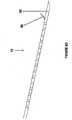
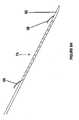
- FIGS 1A and 1Billustrate a mechanism 50 for adjuvant partial breast irradiation.
- the mechanismmay include a table 52 on which a patient lies of their back to have the radioactive sources implanted into the surgery cavity in their breast tissue following breast conservation surgery.
- the mechanismmay also include one or more well known table clamps 54 that are used to clamp one or more stereotactic armatures 56 to the table and fix the stereotactic armatures relative to the table.
- Each stereotactic armature 56may have joints that allow the position of an operational end 59 of the armature to be adjusted and then fixed relative to the table in three dimensions to form a fixed frame of reference.
- the mechanismmay further include a needle retraction stop 57 attached to one stereotactic armature 56 and a fiducial needle fixation assembly 58 attached to another stereotactic armature 56 to form the fixed frame of reference.
- the fiducial needle fixation assembly 58may further include an engagement device 60 that allows a fiducial needle fixation device 62 to be quickly and securely removably fixed to the stereotactic armature 56.
- the patientmay lie on the table with the breast tissue against the fiducial needle fixation assembly 58 so that one or more fiducial needles may be inserted into the breast tissue and the surgery cavity using an electromagnetic imaging system, such as for example ultrasound so that the surgeon can then accurately place the one or more radioactive sources into the tumor bed/surgery cavity using an electromagnetic imaging system, such as for example ultrasound to visualize the tumor bed/surgery cavity due to the one or more fiducial needles as described below in more detail.
- the one or more radioactive sourcesmay be 103 PD seeds and/or seed strands.
- the radioactive seedsmay also be 125 I and or 131 Cs
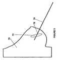
- Figure 2illustrates a view of a breast 70 with a lumpectory site after the surgical removal of the tumor 72 (or surgery cavity when the majority of the tumor has been removed during breast conservation surgery) and
- Figure 3illustrates a view of the breast 70 with the tumor/surgery cavity 72 with a fiducial needle 74 inserted to accurately locate the tumor/surgery cavity to allow the precise placement of the radioactive sources according to the treatment plan.
- each fiducial needle 74may have one or more visualization features 76 (described in more detail below with respect to Figures 4A and 4B ) that can be seen when an electromagnetic source irradiates the breast tissue so that, based on the fiducial needles, the one or more radioactive sources can be precisely placed into the breast tissue according to a treatment plan to kill any tumor cells that were not removed during the breast conservation surgery.
- FIGs 4A and 4Billustrate an example of a fiducial needle 74 that can be used with the mechanism for adjuvant partial breast irradiation shown in Figures 1A and 1B .
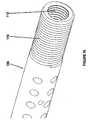
- Each fiducial needle used in the adjuvant partial breast irradiation shown in Figures 1A and 1Bmay have a shaft portion 78, a visualization portion 80 that has the one or more visualization features 76 and a tip portion 82.
- the fiducial needlemay be constructed out of a rigid material and have an enhanced geometry that will facilitate its fixation in the breast tissue.
- the shaft portionmay be constructed out of rod stock and may have a round, square, triangular, hexagonal or octagonal cross section.
- the fiducial needlemay also have a retention features on the tip end that allows the needle to be easily inserted and removed but, once in place, fixate the needle in its location by either tissue encapsulation into features of the needle (as shown in Figure 4C and described below) or by penetration by either a user deployable projection feature or similar structure as shown in Figures 6A-6I which are described below.
- the overall outside diameter of the needleshall be 1.8-0.7 mm (15 gauge to 22 gauge i.e 0.070" to 0.028”) and the needle may have a length of 7.6-30.5 cm (3" to 12").
- the to to the needlemay to
- the needlemay be manufactured out of stainless steel, stainless steel alloys including 304, 316/316L, 321, 347, Inconel 624, 17-7ph, 430/434, Hastelloy C-276, Invar36, and or a polymer based material.
- the needlemay have a sharpened tip to facilitate easy penetration into tissue and the tip may be trocar, pencil and or beveled in its point geometry.
- each visualization feature 76may be geometry that is tailored to promote visualization under imaging.
- each visualization feature 76may further comprise topographic features of elevated or depressed surface characteristics towards the tip of the needle that will help reflect the energy from an imaging system so that the position and orientation of the feature 76 and the fiducial needle can be accurately determined using the imaging system.
- each visualization feature 76may include a depressed region 84 adjacent to an elevated region 86 as shown in Figure 4B .
- Figure 4Cillustrates one technique for fiducial needle fixation into tissue 90. As shown in Figure 4C , once the fiducial needle 74 is inserted into the tissue 90, the tissue may move into the depressed regions 84 (tissue encapsulation) which will cause the fiducial needle to be temporarily anchored into the tissue.
- FIG 5illustrates using an electromagnetic device 92 for visualizing the fiducial needle 74 shown in Figures 4A and 4B .
- the electromagnetic device 92may be an imaging device that generates electromagnetic energy.
- the electromagnetic device 92may be an ultrasound imaging device.
- the electromagnetic device 92may also be fluoroscopy, magnetic resonance imaging (MRI) and or computerized tomography (CT)
- MRImagnetic resonance imaging
- CTcomputerized tomography
- the electromagnetic device 92generates energy that strikes the needle 74 and is reflected by the features 76 of the needle as radiated energy 94 that is received by the electromagnetic device 92 in order to precisely determine the position and orientation of the needle 74 relative to the electromagnetic device 92 (and hence the precise position and orientation of the tumor/surgery cavity into which the radioactive sources may be implanted during the treatment.
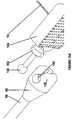
- FIGS 6A - 6Iillustrates examples of a fiducial needle 74 with a retention device 98 that may be used with the mechanism for adjuvant partial breast irradiation shown in Figures 1A and 1B .
- a retention device 100such as a user deployable and retractable barb feature (a user deployable projection) that can be used to fixate the fiducial needle once it is positioned so that the position of the fiducial needle relative to the breast tissue and the mechanism shown in Figures 1A and 1B does not change during the procedure to insert the one or more radioactive sources into the breast tissue so that the position of the one or more radioactive sources is precisely controlled.
- a retention device 100such as a user deployable and retractable barb feature (a user deployable projection) that can be used to fixate the fiducial needle once it is positioned so that the position of the fiducial needle relative to the breast tissue and the mechanism shown in Figures 1A and 1B does not change during the procedure to insert the one or more radioactive sources into the breast tissue so that the position
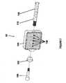
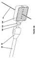
- Figure 7illustrates an example of the fiducial needle fixation device 62 that may be used with the mechanism for adjuvant partial breast irradiation shown in Figures 1A and 1B .
- the fiducial needle fixation device 62may comprise an attachment ball device 100, a fiducial needle lock 102, a template 104 and a locking pin 106 that when attached to each other, lock one or more fiducial needles into the template 104 and rigidly secure the template to the attachment ball device 100 which in turn is rigidly connected to the sterotactic armature.
- the one or more fiducial needlesare inserted into the one or more fiducial needle locations 108 with the locking pin 106 in an unlocked position and then the fiducial needle lock 102 is tightened to a locked position using a set of threads 110 on the locking pin which causes the locking pin 106 to be pulled towards the fiducial needle lock 102 which moves the locking pin into a locking position as will be described below in more detail.
- the fiducial needle lock 102may move from the unlocked position to the locked position using other mechanisms instead of the set of threads.
- the locking of the fiducial needles into a positiondoes not affect any needles in the other holes of the template (holes A0 - A9 through L0- L9) so that those needles (such as needles that deliver the radioactive sources into the treatment site) are not locked into a position.
- the attachment ball device 100may be screwed into an inner set of threads of the locking pin (as shown in Figure 9B ) to provide a rigid but alterable attachment of the template to the attachment ball device 100 so that the attachment ball device may be inserted into the engagement device 60 of the mechanism as shown in Figures 1A and 1B .
- the attachment ball device 100may be attached to the fiducial needle fixation device 62 by a locking mechanism instead of the set of threads.
- Figure 8illustrate more details of the template 104 shown in Figure 7 .
- the templateis a solid/hollow rectangular shaped piece of material (although the template can be other shapes and sizes to accommodate differing tumor/patient sizes) that has the lockable fiducial needle locations 108 as well as the other needle holes that are not lockable as described above.
- Figures 9A and 9Billustrate an example of the locking pin 106 of the template shown in Figures 7 and 8 and Figure 10 illustrate more details the locking pin 106 shown in Figures 9A and 9B .
- the locking pin 106has the set of outer threads 110 that mesh with the fiducial needle lock 102 to tighten the locking pin from an unlocked position to a locked position as described below.
- the locking pin 106may also have a stop 114 that stops the end of the locking pin opposite of the threads 110 and lock it against the end of the template 104 as shown in Figure 11 .
- the locking pin 106also comprises one or more fiducial needle holes 116 (located along a center of the locking pin 106 in one implementation as shown in Figure 9A ) that, when the locking pin is in the unlocked position, the one or more fiducial needles pass through the locking pin.
- the locking pin 106may also have a plurality of needle holes 118 that are slightly larger in diameter than the fiducial needle holes 116 so that, whether the locking pin 106 is in the locked or unlocked position, the locking pin does not lock the needles at any time.
- the locking pin 106may also include a set of internal threads 112 into which the threads of the attachment ball device 100 are threaded to secure the template and locking pin to the attachment ball device 100.
- Figure 11illustrates an assembled fiducial needle fixation device 62 that may be used with the mechanism for adjuvant partial breast irradiation shown in Figures 1A and 1B .
- the locking pinIn the assembled state with the locking pin tightened so that the stop 114 is against the side of the template 104 and the fiducial needle lock 102 is tightened and the attachment ball device 100 is secured to the fiducial needle fixation device 62.
- Figures 12A and 12Bare a cut-away view of the fiducial needle fixation device in an unlocked position for a different number of fiducial needles wherein the template 104 has the locking pin 106 inserted.
- the fiducial needle locations 108 of the templateare aligned with the fiducial needle holes 116 of the locking pin 106 so that the fiducial needle 74 does not have its position locked relative to the template 104 and the fiducial needle can be slid though the template 104 to properly position the fiducial needle relative to the template.
- Figure 13is a cut-away view of the fiducial needle fixation device 62 in an locked position.
- the locking pin 106is tightened so that the fiducial needles locations 108 of the template are not aligned with the fiducial needle holes 116 of the locking pin 106 so that the sides of the fiducial needle holes 116 press against the side of a fiducial needle to lock the fiducial needle position relative to the fiducial needle fixation device 62.
- the surgeoncan precisely implant radioactive sources into the tissue.
- Figures 14A-14Cillustrate different examples of the fiducial needle fixation device 62 with fiducial needles 74 locked into the fiducial needle fixation device.
- the fiducial needle fixation device 62with four fiducial needles locked into the fiducial needle fixation device, three fiducial needles locked into the fiducial needle fixation device and one fiducial needle locked into the fiducial needle fixation device as shown.
- the fiducial needle fixation devicepermits one or more (up to five in the implementation shown) to be locked into the fiducial needle fixation device.
- the fiducial needle fixation devicemay also be constructed to allow additional fiducial needles to be positioned and locked into the fiducial needle fixation device.
- FIGs 15A - 15Cillustrate the fiducial needle fixation device 62 with locked fiducial needles 74 being inserted into the engagement device 60.
- the engagement device 60may comprise a head portion 120 that is rigidly attached to the stereotactic armature 56 wherein the head portion has a socket region 122.
- the ball of the attachment ball device 100can be quickly inserted into the socket region 122 to secure the fiducial needle fixation device 62 fixedly to the stereotactic armature 56, but allow the fiducial needle fixation device 62 to also be rapidly removed from the engagement device 60 as needed.
- Figure 16illustrates a method 130 for adjuvant partial breast irradiation using the fiducial needle fixation mechanisms.
- the method describedcan be implemented using the various devices and mechanisms described above and allow the surgeon to precisely implant radioactive sources into the tissue.
- the one or more stereotactic armaturesare attached to the operating table as shown above in Figures 1A and 1B .
- the patientis prepared for surgery as is well known (134).
- the patientmay have her arm above her head on the side of the breast to be treated.
- the surgeon or technicianinserts one or more fiducial fixation needles, under guidance by a medical imaging technology, into the site (136) such as the lumpectomy site when a breast cancer patient is being treated.
- the fiducial needle fixation deviceis attached to the one or more fiducial needles (138) with the fiducial needle fixation device is the unlocked position.
- the fiducial needle fixation deviceis tightened into the locked position (140).
- the ball of the assembled and locked fiducial needle fixation deviceis slipped into the quick connect socket of the stereotactic armature (142) to fix the fiducial needle fixation device with respect to the operating table and the patient.
- the armaturesare then tightened (144) to immobilize the system.
- the surgeonmay begin to insert the brachytherapy needles containing the radioactive sources and/or source strands through the template and into the patient per the previously determined coordinate locations of the prescription treatment plan.
- the methodis completed.
Landscapes
- Health & Medical Sciences (AREA)
- Life Sciences & Earth Sciences (AREA)
- Engineering & Computer Science (AREA)
- Biomedical Technology (AREA)
- Pathology (AREA)
- Animal Behavior & Ethology (AREA)
- General Health & Medical Sciences (AREA)
- Public Health (AREA)
- Veterinary Medicine (AREA)
- Surgery (AREA)
- Nuclear Medicine, Radiotherapy & Molecular Imaging (AREA)
- Heart & Thoracic Surgery (AREA)
- Radiology & Medical Imaging (AREA)
- Medical Informatics (AREA)
- Molecular Biology (AREA)
- Biophysics (AREA)
- Physics & Mathematics (AREA)
- Oral & Maxillofacial Surgery (AREA)
- Human Computer Interaction (AREA)
- Radiation-Therapy Devices (AREA)
- Apparatus For Radiation Diagnosis (AREA)
Description
- The disclosure relates generally to a mechanism for radiation oncology.
- When women are treated for breast cancer (which is the most commonly diagnosed cancer in women), they can opt for a mastectomy (complete removal of the breast tissue) or a breast conservation surgery. Due to the use of widespread screening mammograms, women are diagnosed with localized and early-stage disease so that the breast conservation surgery followed by radiation treatment may be used. The typical radiation treatment is adjuvant breast radiation. While the adjuvant breast radiation results in good survival rates, adjuvant breast radiation treatment typically takes 3.5 to 7 weeks which is too long. In addition, since the adjuvant breast radiation treatment is typically provided using external beam radiation, there is a greater risk of acute skin reactions due to the healthy tissue interaction with the radiation.
- As a result, accelerated partial breast irradiation may be used which results in a quicker treatment time and less radiation-induced acute skin reactions. One technique used for the accelerated partial breast irradiation is brachytherapy. In one method, radioactive sources are permanently implanted into the breast tissue at the site of the surgery wherein the radioactive sources may be high dose or low dose.
- Currently there are a handful of ways to insert radioactive sources into breast tissue. One is by a free hand method, another uses a compressive template device to temporary hold insertion catheters and the last uses a locking template system and non-fixated fiducial needle. These methods are limited in that they do not ensure the sources are placed in the desired location as prescribed by the
treatment plan 100% of the time. The lack of ability to place the radioactive sources in the desired location means that the remaining tumor margin is not receiving the appropriate radiation and healthy tissue is receiving unwanted radiation. - In the high dose rate brachytherapy area, a clinician would place hollow catheters into the breast to facilitate the insertion of a temporary radioactive source per a treatment plan which are then removed once the treatment is competed. The placement of these catheters may be by either free hand directly into the breast or by free hand though compressive template systems used to stereo- tactically immobilize the breast. Both Varian Medical Systems and Nucletron offer commercially available template immobilization products.
- In the low dose rate brachytherapy area, one method for permanent breast radioactive seed implantation is described in detail in "First Report of a Permanent Breast 103PD Seed Implant As Adjuvant Radiation Treatment for Early-Stage Breast Cancer", Dr. Jean-Philippe Pignol et al., International Journal of Radiation Oncology Biological Physics, Vol. 64, No. 1, pp. 176-181 (2006) which is incorporated herein by reference. This method uses a non-fixated fiducial needle, locking template and stereotactic fixation to insert lose dose rate (LDR) radioactive source strands into the treatment site. In this method, the fiducial needle can migrate/move once inserted thus changing the depth at which the source strands are deployed. In addition, the system is very cumbersome to use and is not user intuitive.
- Document
WO2004014215 (A2 ) discloses a brachytherapy seed deployment system for use in any of a variety of medical procedures such as radiation treatment of the prostate gland. In one embodiment, the system includes a number of brachytherapy seed deployment needles, each preloaded with brachytherapy seeds in patterns and activities predetermined for a unique patient. - Further, document
WO0172202 A2 - Thus, it is desirable to provide a mechanism to facilitate the insertion of radioactive sources/source strands into soft tissue, such as breast tissue and a method that utilizes this mechanism with the goal of improving the reproducibility of the procedure and ensuring that the sources are reliably and consistently inserted in an exact position per a patient prescription treatment plan from patient to patient as well as improve the ease-of-use of the device and procedure. It is to this end that the disclosure is directed. The invention is defined in the claims. Other embodiments are described for illustrative purposes.
Figures 1A and1B illustrate a mechanism for adjuvant partial breast irradiation;Figure 2 illustrates a view of a breast with a tumor;Figure 3 illustrates a view of a breast with a tumor with a fiducial needle inserted to accurately locate the tumor;Figures 4A and4B illustrate an example of a fiducial needle that can be used with the mechanism for adjuvant partial breast irradiation shown inFigures 1A and1B ;Figure 4C illustrates one technique for fiducial needle fixation;Figure 5 illustrates using an electromagnetic device for visualizing the fiducial needle shown inFigures 4A and4B ;Figures 6A - 6I illustrates examples of a fiducial needle with a retention device that may be used with the mechanism for adjuvant partial breast irradiation shown inFigures 1A and1B ;Figure 7 illustrates an example of a fiducial needle fixation device that may be used with the mechanism for adjuvant partial breast irradiation shown inFigures 1A and1B ;Figure 8 illustrate more details of the template shown inFigure 7 ;Figures 9A and9B illustrate an example of a locking pin of the template shown inFigures 7 and8 ;Figure 10 illustrate more details the locking pin shown inFigures 9A and9B ;Figure 11 illustrates an assembled fiducial needle fixation device that may be used with the mechanism for adjuvant partial breast irradiation shown inFigures 1A and1B ;Figures 12A and12B are a cut-away view of the fiducial needle fixation device in an unlocked position;Figure 13 is a cut-away view of the fiducial needle fixation device in an locked position;Figures 14A-14C illustrate different examples of the fiducial needle fixation device with fiducial needles locked into the fiducial needle fixation device;Figures 15A - 15C illustrate the fiducial needle fixation device with locked fiducial needles being inserted into the engagement device; andFigure 16 illustrates a method for adjuvant partial breast irradiation using the fiducial needle fixation mechanisms.- The disclosure is particularly applicable to low dose radioactive source implantation into breast tissue and it is in this context that the disclosure will be described. It will be appreciated, however, that the mechanism has greater utility since the mechanism can be used to implant various different radioactive sources into various different tissues.
Figures 1A and1B illustrate amechanism 50 for adjuvant partial breast irradiation. The mechanism may include a table 52 on which a patient lies of their back to have the radioactive sources implanted into the surgery cavity in their breast tissue following breast conservation surgery. The mechanism may also include one or more well knowntable clamps 54 that are used to clamp one or morestereotactic armatures 56 to the table and fix the stereotactic armatures relative to the table. Eachstereotactic armature 56 may have joints that allow the position of anoperational end 59 of the armature to be adjusted and then fixed relative to the table in three dimensions to form a fixed frame of reference. The mechanism may further include aneedle retraction stop 57 attached to onestereotactic armature 56 and a fiducialneedle fixation assembly 58 attached to anotherstereotactic armature 56 to form the fixed frame of reference.- As shown in
Figure 1B , the fiducialneedle fixation assembly 58 may further include anengagement device 60 that allows a fiducialneedle fixation device 62 to be quickly and securely removably fixed to thestereotactic armature 56. Generally, the patient may lie on the table with the breast tissue against the fiducialneedle fixation assembly 58 so that one or more fiducial needles may be inserted into the breast tissue and the surgery cavity using an electromagnetic imaging system, such as for example ultrasound so that the surgeon can then accurately place the one or more radioactive sources into the tumor bed/surgery cavity using an electromagnetic imaging system, such as for example ultrasound to visualize the tumor bed/surgery cavity due to the one or more fiducial needles as described below in more detail. In one implementation, the one or more radioactive sources may be103PD seeds and/or seed strands. The radioactive seeds may also be125I and or131Cs Figure 2 illustrates a view of abreast 70 with a lumpectory site after the surgical removal of the tumor 72 (or surgery cavity when the majority of the tumor has been removed during breast conservation surgery) andFigure 3 illustrates a view of thebreast 70 with the tumor/surgery cavity 72 with afiducial needle 74 inserted to accurately locate the tumor/surgery cavity to allow the precise placement of the radioactive sources according to the treatment plan. In a process to place one or more radioactive sources into the breast tissue/surgery cavity following the breast conservation surgery, there may be one or morefiducial needles 74 inserted although only onefiducial needle 74 is shown inFigure 3 for illustration purposes. As described below, eachfiducial needle 74 may have one or more visualization features 76 (described in more detail below with respect toFigures 4A and4B ) that can be seen when an electromagnetic source irradiates the breast tissue so that, based on the fiducial needles, the one or more radioactive sources can be precisely placed into the breast tissue according to a treatment plan to kill any tumor cells that were not removed during the breast conservation surgery.Figures 4A and4B illustrate an example of afiducial needle 74 that can be used with the mechanism for adjuvant partial breast irradiation shown inFigures 1A and1B . Each fiducial needle used in the adjuvant partial breast irradiation shown inFigures 1A and1B may have ashaft portion 78, avisualization portion 80 that has the one or more visualization features 76 and atip portion 82. The fiducial needle may be constructed out of a rigid material and have an enhanced geometry that will facilitate its fixation in the breast tissue. The shaft portion may be constructed out of rod stock and may have a round, square, triangular, hexagonal or octagonal cross section. The fiducial needle may also have a retention features on the tip end that allows the needle to be easily inserted and removed but, once in place, fixate the needle in its location by either tissue encapsulation into features of the needle (as shown inFigure 4C and described below) or by penetration by either a user deployable projection feature or similar structure as shown inFigures 6A-6I which are described below. In one implementation, the overall outside diameter of the needle shall be 1.8-0.7 mm (15 gauge to 22 gauge i.e 0.070" to 0.028") and the needle may have a length of 7.6-30.5 cm (3" to 12"). The to to the needle may to The needle may be manufactured out of stainless steel, stainless steel alloys including 304, 316/316L, 321, 347, Inconel 624, 17-7ph, 430/434, Hastelloy C-276, Invar36, and or a polymer based material. The needle may have a sharpened tip to facilitate easy penetration into tissue and the tip may be trocar, pencil and or beveled in its point geometry.- As shown in
Figure 4B , the geometry of the needle may be optimized to facilitate visualization with various clinical imaging modalities using the visualization features 76. Eachvisualization feature 76 may be geometry that is tailored to promote visualization under imaging. For example, eachvisualization feature 76 may further comprise topographic features of elevated or depressed surface characteristics towards the tip of the needle that will help reflect the energy from an imaging system so that the position and orientation of thefeature 76 and the fiducial needle can be accurately determined using the imaging system. In one implementation, eachvisualization feature 76 may include adepressed region 84 adjacent to anelevated region 86 as shown inFigure 4B . Figure 4C illustrates one technique for fiducial needle fixation intotissue 90. As shown inFigure 4C , once thefiducial needle 74 is inserted into thetissue 90, the tissue may move into the depressed regions 84 (tissue encapsulation) which will cause the fiducial needle to be temporarily anchored into the tissue.Figure 5 illustrates using anelectromagnetic device 92 for visualizing thefiducial needle 74 shown inFigures 4A and4B . Theelectromagnetic device 92 may be an imaging device that generates electromagnetic energy. In one implementation, theelectromagnetic device 92 may be an ultrasound imaging device. Theelectromagnetic device 92 may also be fluoroscopy, magnetic resonance imaging (MRI) and or computerized tomography (CT) As shown, theelectromagnetic device 92 generates energy that strikes theneedle 74 and is reflected by thefeatures 76 of the needle as radiatedenergy 94 that is received by theelectromagnetic device 92 in order to precisely determine the position and orientation of theneedle 74 relative to the electromagnetic device 92 (and hence the precise position and orientation of the tumor/surgery cavity into which the radioactive sources may be implanted during the treatment.Figures 6A - 6I illustrates examples of afiducial needle 74 with aretention device 98 that may be used with the mechanism for adjuvant partial breast irradiation shown inFigures 1A and1B . These figures show a plurality of different examples of aretention device 100, such as a user deployable and retractable barb feature (a user deployable projection) that can be used to fixate the fiducial needle once it is positioned so that the position of the fiducial needle relative to the breast tissue and the mechanism shown inFigures 1A and1B does not change during the procedure to insert the one or more radioactive sources into the breast tissue so that the position of the one or more radioactive sources is precisely controlled. Any of the different examples shown in these figures may also be combined together. Now, the fiducialneedle fixation device 62 is described in more detail.Figure 7 illustrates an example of the fiducialneedle fixation device 62 that may be used with the mechanism for adjuvant partial breast irradiation shown inFigures 1A and1B . In one implementation, the fiducialneedle fixation device 62 may comprise anattachment ball device 100, afiducial needle lock 102, atemplate 104 and alocking pin 106 that when attached to each other, lock one or more fiducial needles into thetemplate 104 and rigidly secure the template to theattachment ball device 100 which in turn is rigidly connected to the sterotactic armature. To lock the one or more fiducial needles into thetemplate 104 at one or morefiducial needle locations 108 of the template, the one or more fiducial needles are inserted into the one or morefiducial needle locations 108 with thelocking pin 106 in an unlocked position and then thefiducial needle lock 102 is tightened to a locked position using a set ofthreads 110 on the locking pin which causes thelocking pin 106 to be pulled towards thefiducial needle lock 102 which moves the locking pin into a locking position as will be described below in more detail. Alternatively, thefiducial needle lock 102 may move from the unlocked position to the locked position using other mechanisms instead of the set of threads.- In the fiducial
needle fixation device 62, the locking of the fiducial needles into a position does not affect any needles in the other holes of the template (holes A0- A9 through L0- L9) so that those needles (such as needles that deliver the radioactive sources into the treatment site) are not locked into a position. Once the fiducial needles are locked into position, theattachment ball device 100 may be screwed into an inner set of threads of the locking pin (as shown inFigure 9B ) to provide a rigid but alterable attachment of the template to theattachment ball device 100 so that the attachment ball device may be inserted into theengagement device 60 of the mechanism as shown inFigures 1A and1B . Alternatively, theattachment ball device 100 may be attached to the fiducialneedle fixation device 62 by a locking mechanism instead of the set of threads. Figure 8 illustrate more details of thetemplate 104 shown inFigure 7 . In one example, the template is a solid/hollow rectangular shaped piece of material (although the template can be other shapes and sizes to accommodate differing tumor/patient sizes) that has the lockablefiducial needle locations 108 as well as the other needle holes that are not lockable as described above. Once the one or more fiducial needles are locked into position and the fiducialneedle fixation device 62 is locked into position relative to themechanism 50, the needles with the radioactive sources can be inserted into the template holes at precisely known locations to insert and implant the radioactive sources into the breast tissue according to the coordinated locations of the prescription treatment plan.Figures 9A and9B illustrate an example of thelocking pin 106 of the template shown inFigures 7 and8 andFigure 10 illustrate more details the lockingpin 106 shown inFigures 9A and9B . Thelocking pin 106 has the set ofouter threads 110 that mesh with thefiducial needle lock 102 to tighten the locking pin from an unlocked position to a locked position as described below. Thelocking pin 106 may also have astop 114 that stops the end of the locking pin opposite of thethreads 110 and lock it against the end of thetemplate 104 as shown inFigure 11 . Thelocking pin 106 also comprises one or more fiducial needle holes 116 (located along a center of thelocking pin 106 in one implementation as shown inFigure 9A ) that, when the locking pin is in the unlocked position, the one or more fiducial needles pass through the locking pin. When the locking pin is in the locked position (as shown inFigure 13 ), the sides of the fiducial needle holes 116 are pressed against the side of the one or more fiducial needles to lock the fiducial needle position relative to the template. Thelocking pin 106 may also have a plurality of needle holes 118 that are slightly larger in diameter than the fiducial needle holes 116 so that, whether thelocking pin 106 is in the locked or unlocked position, the locking pin does not lock the needles at any time. As shown inFigure 9B and10 , the lockingpin 106 may also include a set ofinternal threads 112 into which the threads of theattachment ball device 100 are threaded to secure the template and locking pin to theattachment ball device 100.Figure 11 illustrates an assembled fiducialneedle fixation device 62 that may be used with the mechanism for adjuvant partial breast irradiation shown inFigures 1A and1B . In the assembled state with the locking pin tightened so that thestop 114 is against the side of thetemplate 104 and thefiducial needle lock 102 is tightened and theattachment ball device 100 is secured to the fiducialneedle fixation device 62.Figures 12A and12B are a cut-away view of the fiducial needle fixation device in an unlocked position for a different number of fiducial needles wherein thetemplate 104 has thelocking pin 106 inserted. In the unlocked position as shown inFigures 12A and12B , thefiducial needle locations 108 of the template are aligned with the fiducial needle holes 116 of thelocking pin 106 so that thefiducial needle 74 does not have its position locked relative to thetemplate 104 and the fiducial needle can be slid though thetemplate 104 to properly position the fiducial needle relative to the template.Figure 13 is a cut-away view of the fiducialneedle fixation device 62 in an locked position. In the locked position, the lockingpin 106 is tightened so that thefiducial needles locations 108 of the template are not aligned with the fiducial needle holes 116 of thelocking pin 106 so that the sides of the fiducial needle holes 116 press against the side of a fiducial needle to lock the fiducial needle position relative to the fiducialneedle fixation device 62. When the fiducial needle position is locked relative to the fiducialneedle fixation device 62, the surgeon can precisely implant radioactive sources into the tissue.Figures 14A-14C illustrate different examples of the fiducialneedle fixation device 62 withfiducial needles 74 locked into the fiducial needle fixation device. In particular, the fiducialneedle fixation device 62 with four fiducial needles locked into the fiducial needle fixation device, three fiducial needles locked into the fiducial needle fixation device and one fiducial needle locked into the fiducial needle fixation device as shown. Thus, the fiducial needle fixation device permits one or more (up to five in the implementation shown) to be locked into the fiducial needle fixation device. However, the fiducial needle fixation device may also be constructed to allow additional fiducial needles to be positioned and locked into the fiducial needle fixation device.Figures 15A - 15C illustrate the fiducialneedle fixation device 62 with lockedfiducial needles 74 being inserted into theengagement device 60. Theengagement device 60 may comprise ahead portion 120 that is rigidly attached to thestereotactic armature 56 wherein the head portion has asocket region 122. As shown inFigures 15A and15B , the ball of theattachment ball device 100 can be quickly inserted into thesocket region 122 to secure the fiducialneedle fixation device 62 fixedly to thestereotactic armature 56, but allow the fiducialneedle fixation device 62 to also be rapidly removed from theengagement device 60 as needed.Figure 16 illustrates amethod 130 for adjuvant partial breast irradiation using the fiducial needle fixation mechanisms. The method described can be implemented using the various devices and mechanisms described above and allow the surgeon to precisely implant radioactive sources into the tissue. In afirst process 132, the one or more stereotactic armatures are attached to the operating table as shown above inFigures 1A and1B . Then, the patient is prepared for surgery as is well known (134). For adjuvant partial breast irradiation treatment, the patient may have her arm above her head on the side of the breast to be treated. Next, the surgeon or technician inserts one or more fiducial fixation needles, under guidance by a medical imaging technology, into the site (136) such as the lumpectomy site when a breast cancer patient is being treated. Next, the fiducial needle fixation device is attached to the one or more fiducial needles (138) with the fiducial needle fixation device is the unlocked position. For the adjuvant partial breast irradiation, it is desirable to have the fiducial needle fixation device positioned adjacent and touching the breast tissue. Once properly positioned, the fiducial needle fixation device is tightened into the locked position (140). The ball of the assembled and locked fiducial needle fixation device is slipped into the quick connect socket of the stereotactic armature (142) to fix the fiducial needle fixation device with respect to the operating table and the patient. The armatures are then tightened (144) to immobilize the system. Once the system is immobilize (which ensures precise placement of the radioactive sources), the surgeon may begin to insert the brachytherapy needles containing the radioactive sources and/or source strands through the template and into the patient per the previously determined coordinate locations of the prescription treatment plan. Once the implantation of the radioactive sources is completed, the method is completed.- While the foregoing has been with reference to a particular embodiment of the invention, it will be appreciated by those skilled in the art that changes in this embodiment may be made without departing from the principles of the invention, the scope of which is defined by the appended claims.
Claims (19)
- A brachytherapy radioactive source implantation device, comprising:one or more fiducial needles (74), each fiducial needle having a tip portion, a visualization portion and a shaft portion, the visualization portion having one or more visualization features that allow the position of the fiducial needle within tissue to be precisely determined when visualized using an imaging device;one or more radioactive source needles; anda needle fixation device (62) having one or more fiducial needle holes (108) and a plurality of radioactive source needle holes, the one or more one or more fiducial needle holes (116) being lockable to lock one or more fiducial needles (74) into a fixed position relative to the needle fixation device (62) and the plurality of radioactive source needle holes not being lockable.
- The device of claim 1, wherein the needle fixation device (62) further comprises an attachment ball device (100) that threadable attaches the needle fixation device (62) to a fixed frame of reference, a fiducial needle lock, a template having the one or more fiducial needle holes and the plurality of radioactive source needle holes and a locking pin wherein the locking pin is tightenable using the fiducial needle lock to lock the position of the one or more fiducial needles (74) relative to the template.
- The device of claim 1, wherein the needle fixation device (62) further comprises an attachment ball device (100) that is adapted to attach the needle fixation device (62) to a fixed frame of reference, a fiducial needle lock, a template having the one or more fiducial needle holes and the plurality of radioactive source needle holes and a locking pin wherein the locking pin is tightenable using the fiducial needle lock to lock the position of the one or more fiducial needles (74) relative to the template.
- The device of claim 2, wherein the template further comprises a parallelogram array of the radioactive source needle holes and wherein the one or more fiducial needle holes are along a center line of the template.
- The device of claim 2, wherein the locking pin further comprises a set of fiducial needle holes wherein a side of the fiducial needle holes are pressable against the one or more fiducial needles (74) in the needle fixation device when the locking pin is in a locked position, a set of radioactive source needle holes, a set of outer threads that are adapted to cooperate with the fiducial needle lock to move the locking pin between an unlocked position and a locked position and a set of inner threads that cooperate with the attachment ball device (100) to attach the needle fixation device to the fixed frame of reference.
- The device of claim 1, wherein each visualization feature further comprises a recessed portion and a raised portion that are adapted to reflect the energy from the imaging device.
- The device of claim 6, wherein the imaging device further comprises an ultrasound device that is adapted to generate ultrasound energy.
- The device of claim 1, wherein each shaft portion has one of a round cross section, a square cross section, a triangular cross section, a hexagonal cross section and a octagonal cross section.
- The device of claim 1, wherein each fiducial needle further comprises a retention feature that is adapted to anchor the fiducial needle into the tissue.
- The device of claim 9, wherein the retention feature further comprises one or more user deployable projections that are adapted to anchor the fiducial needle into the tissue.
- The device of claim 2 further comprising an engagement device that is adapted to removably secure the needle fixation device to the fixed frame of reference.
- The device of claim 11, wherein the engagement device further comprises socket portion and wherein the attachment ball device further comprises a ball portion wherein the ball portion is removably insertable into the socket portion to secure the needle fixation device to the fixed frame of reference.
- The device of claim 12 further comprising a sterotactic armature removably attachable to an operating table wherein the stereotactic armature further comprises the engagement device so that the needle fixation device is fixable in position relative to the operating table.
- The fiducial needle fixation device of claim 1, further comprising:a body portion;wherein the one or more fiducial needle holes are included in the body portion; andwherein the the plurality of radioactive source needle holes are included in the body portion.
- The device of claim 14 further comprising an attachment ball device (100) that is adapted to threadably attach the needle fixation device to a fixed frame of reference, a fiducial needle lock, a template having the one or more fiducial needle holes and the plurality of radioactive source needle holes and a locking pin wherein the locking pin is tightenable using the fiducial needle lock to lock the position of the one or more fiducial needles (74) relative to the template.
- The device of claim 14 further comprising an attachment ball device (100) that is adapted to attach the needle fixation device to a fixed frame of reference, a fiducial needle lock, a template having the one or more fiducial needle holes and the plurality of radioactive source needle holes and a locking pin wherein the locking pin is tightenable using the fiducial needle lock to lock the position of the one or more fiducial needles (74) relative to the template.
- The device of claim 15, wherein the template further comprises a parallelogram array of the radioactive source needle holes and wherein the one or more fiducial needle holes are along a center line of the template.
- The device of claim 15, wherein the locking pin further comprises a set of fiducial needle holes wherein a side of the fiducial needle holes are pressable against the one or more fiducial needles (74) in the needle fixation device when the looking pin is in a locked position, a set of radioactive source needle holes, a set of outer threads that is adapted to cooperate with the fiducial needle lock to move the locking pin between an unlocked position and a lacked position and a set of inner threads that is adapted to cooperate with the attachment ball device (100) to attach the needle fixation device to the fixed frame of reference.
- The device of claim 1, wherein the tip portion of the fiducial needle further comprises one of a trocar point geometry, a pencil point geometry and a beveled point geometry.
Applications Claiming Priority (2)
| Application Number | Priority Date | Filing Date | Title |
|---|---|---|---|
| US12/427,667US8764619B2 (en) | 2009-04-21 | 2009-04-21 | Brachytherapy fiducial needle fixation system and method |
| PCT/US2010/031937WO2010124022A1 (en) | 2009-04-21 | 2010-04-21 | Brachytherapy fiducial needle fixation system and method |
Publications (3)
| Publication Number | Publication Date |
|---|---|
| EP2421433A1 EP2421433A1 (en) | 2012-02-29 |
| EP2421433A4 EP2421433A4 (en) | 2012-09-19 |
| EP2421433B1true EP2421433B1 (en) | 2014-06-04 |
Family
ID=42981485
Family Applications (1)
| Application Number | Title | Priority Date | Filing Date |
|---|---|---|---|
| EP10767725.4ANot-in-forceEP2421433B1 (en) | 2009-04-21 | 2010-04-21 | Brachytherapy fiducial needle fixation system |
Country Status (6)
| Country | Link |
|---|---|
| US (3) | US8764619B2 (en) |
| EP (1) | EP2421433B1 (en) |
| CA (1) | CA2762591C (en) |
| TW (1) | TWI426888B (en) |
| WO (1) | WO2010124022A1 (en) |
| ZA (1) | ZA201108524B (en) |
Families Citing this family (17)
| Publication number | Priority date | Publication date | Assignee | Title |
|---|---|---|---|---|
| US8968289B2 (en)* | 2010-10-22 | 2015-03-03 | Covidien Lp | Microwave spacers and methods of use |
| EP2852352B1 (en)* | 2012-05-04 | 2021-09-01 | Roger Khouri | Surgical tools |
| USD755385S1 (en) | 2013-09-20 | 2016-05-03 | Kobold, Llc | Brachytherapy template |
| US10653450B2 (en)* | 2015-09-30 | 2020-05-19 | Boston Scientific Scimed, Inc. | Surgical tool control devices and methods of using the same |
| AU2018230771B2 (en)* | 2017-03-08 | 2023-10-05 | Coh Holdco Inc. | Adjustable brachytherapy template and template holder |
| WO2018167002A1 (en) | 2017-03-16 | 2018-09-20 | Koninklijke Philips N.V. | Tilt-controlled grid |
| EP3381513A1 (en) | 2017-03-30 | 2018-10-03 | Servicio Cántabro de Salud | System and device for positioning medical needles |
| US11529432B2 (en) | 2017-05-11 | 2022-12-20 | Alpha Tau Medical Ltd. | Polymer coatings for brachytherapy devices |
| MX2020008829A (en) | 2018-03-08 | 2020-10-05 | Alpha Tau Medical Ltd | RADIOTHERAPY SEEDS AND APPLICATORS. |
| RU2020130217A (en) | 2018-04-02 | 2022-05-04 | Альфа Тау Медикал Лтд. | CONTROLLED RELEASE OF RADIONUCLIDES |
| EP3632579A1 (en)* | 2018-10-05 | 2020-04-08 | Koninklijke Philips N.V. | Interventional device with pvdf ultrasound detector |
| US11504546B2 (en)* | 2019-02-28 | 2022-11-22 | Cowles Ventures, Llc | Needle guidance device for brachytherapy and method of use |
| US20200276455A1 (en)* | 2019-02-28 | 2020-09-03 | Breast Microseed, Inc. | Apparatus for precise positioning of brachytherapy template |
| US11524176B2 (en)* | 2019-03-14 | 2022-12-13 | Cowles Ventures, Llc | Locator for placement of fiducial support device method |
| AU2021400142B2 (en) | 2020-12-16 | 2024-11-21 | Alpha Tau Medical Ltd. | Diffusing alpha-emitters radiation therapy with enhanced beta treatment |
| CA3221690A1 (en)* | 2021-06-08 | 2022-12-15 | Emily Lin | Customized brachytherapy needle template and method |
| CA3221691A1 (en)* | 2021-06-08 | 2022-12-15 | Cowles Ventures, Llc | Automated brachytherapy with robotics and/or image guidance |
Family Cites Families (20)
| Publication number | Priority date | Publication date | Assignee | Title |
|---|---|---|---|---|
| US4697575A (en)* | 1984-11-21 | 1987-10-06 | Henry Ford Hospital | Delivery system for interstitial radiation therapy including substantially non-deflecting elongated member |
| US5279309A (en)* | 1991-06-13 | 1994-01-18 | International Business Machines Corporation | Signaling device and method for monitoring positions in a surgical operation |
| US5759154A (en)* | 1996-12-23 | 1998-06-02 | C. R. Bard, Inc. | Print mask technique for echogenic enhancement of a medical device |
| US5961527A (en)* | 1997-01-22 | 1999-10-05 | Barzell Whitmore Maroon Bells, Inc. | Omni-directional precision instrument platform |
| US5961529A (en)* | 1998-01-12 | 1999-10-05 | Arnold; James E. | Hourglass-shaped dermal punch and methods for its use |
| US6095967A (en)* | 1998-03-25 | 2000-08-01 | Manan Medical Products, Inc. | Isotope seeding system that releases radioactive seeds for treatment of cancerous cells |
| US6200255B1 (en)* | 1998-10-30 | 2001-03-13 | University Of Rochester | Prostate implant planning engine for radiotherapy |
| WO2001028631A1 (en)* | 1999-10-15 | 2001-04-26 | Deschutes Medical Products, Inc. | Brachytherapy instrument and methods |
| US6579262B1 (en)* | 2000-01-25 | 2003-06-17 | Mick Radio-Nuclear Instruments, Inc. | Brachytherapy needle implantation template |
| US6361487B1 (en) | 2000-03-09 | 2002-03-26 | Neoseed Technology Llc | Method and apparatus for brachytherapy treatment of prostate disease |
| US6846282B1 (en)* | 2000-06-09 | 2005-01-25 | Varian Medical Systems, Inc. | Brachytherapy apparatus and methods |
| US6949064B2 (en) | 2000-10-20 | 2005-09-27 | Bard Brachytherapy, Inc. | Brachytherapy seed deployment system |
| US6508786B2 (en)* | 2001-05-22 | 2003-01-21 | Ethicon Endo-Surgery, Inc. | Needle position lock |
| US6549802B2 (en)* | 2001-06-07 | 2003-04-15 | Varian Medical Systems, Inc. | Seed localization system and method in ultrasound by fluoroscopy and ultrasound fusion |
| DE60324448D1 (en)* | 2002-09-10 | 2008-12-11 | Cianna Medical Inc | brachytherapy |
| GB0504988D0 (en) | 2005-03-10 | 2005-04-20 | Emcision Ltd | Device and method for the treatment of diseased tissue such as tumors |
| US7527593B2 (en)* | 2005-06-11 | 2009-05-05 | Fidel Howard F | Active template guide plate and system and method for utilizing same |
| US7736293B2 (en)* | 2005-07-22 | 2010-06-15 | Biocompatibles Uk Limited | Implants for use in brachytherapy and other radiation therapy that resist migration and rotation |
| US20070265487A1 (en)* | 2006-05-09 | 2007-11-15 | Worldwide Medical Technologies Llc | Applicators for use in positioning implants for use in brachytherapy and other radiation therapy |
| NL1031786C1 (en)* | 2006-05-10 | 2007-11-13 | Isodose Control Intellectual P | Catheter needle for internal irradiation of a tumor in a body part. |
- 2009
- 2009-04-21USUS12/427,667patent/US8764619B2/enactiveActive
- 2010
- 2010-04-21WOPCT/US2010/031937patent/WO2010124022A1/enactiveApplication Filing
- 2010-04-21CACA2762591Apatent/CA2762591C/enactiveActive
- 2010-04-21TWTW099112521Apatent/TWI426888B/ennot_activeIP Right Cessation
- 2010-04-21EPEP10767725.4Apatent/EP2421433B1/ennot_activeNot-in-force
- 2011
- 2011-11-21ZAZA2011/08524Apatent/ZA201108524B/enunknown
- 2014
- 2014-06-24USUS14/313,978patent/US10449387B2/enactiveActive
- 2017
- 2017-07-21USUS15/657,043patent/US10456592B2/enactiveActive
Also Published As
| Publication number | Publication date |
|---|---|
| US20140309525A1 (en) | 2014-10-16 |
| WO2010124022A1 (en) | 2010-10-28 |
| EP2421433A4 (en) | 2012-09-19 |
| US10449387B2 (en) | 2019-10-22 |
| TW201039797A (en) | 2010-11-16 |
| TWI426888B (en) | 2014-02-21 |
| US20100268014A1 (en) | 2010-10-21 |
| US10456592B2 (en) | 2019-10-29 |
| CA2762591A1 (en) | 2010-10-28 |
| US8764619B2 (en) | 2014-07-01 |
| US20170319871A1 (en) | 2017-11-09 |
| CA2762591C (en) | 2016-10-25 |
| ZA201108524B (en) | 2012-07-25 |
| EP2421433A1 (en) | 2012-02-29 |
Similar Documents
| Publication | Publication Date | Title |
|---|---|---|
| EP2421433B1 (en) | Brachytherapy fiducial needle fixation system | |
| US20220347489A1 (en) | Dosimetrically customizable brachytherapy carriers and methods thereof in the treatment of tumors | |
| EP1553886B1 (en) | Elongated marker for soft tissue volume identification | |
| EP2540241B1 (en) | Fiducial deployment needle system | |
| US20030153850A1 (en) | Method and apparatus for image-guided therapy | |
| CN105451816B (en) | Medical device for radiotherapy treatment | |
| US20240342505A1 (en) | Radiation shielding apparatus for implantable radioactive seeds | |
| US20230173302A1 (en) | Locator for placement of fiducial support device method | |
| WO2015142316A1 (en) | Dosimetrically customizable brachytherapy carriers and methods thereof in the treatment of tumors | |
| Holm et al. | Transperineal 125iodine seed implantation in prostatic cancer guided by transrectal ultrasonography | |
| US20070265486A1 (en) | Catheter needle for internally irradiating a tumor in a body part | |
| CN111671504A (en) | A multifunctional trocar for distributed particle implantation and biopsy | |
| US20230135830A1 (en) | Needle guidance device for brachytherapy and method of use | |
| CN201921324U (en) | Brach therapy device and system | |
| CN204839582U (en) | Fixing device in art of pjncture needle | |
| CN201921325U (en) | Brachytherapy adapter and brachytherapy system | |
| JP2020523155A (en) | Applicator device for interventional radiotherapy (brachytherapy) and perineal intervention and/or diagnostic procedure | |
| US20210008390A1 (en) | Medical device for radiotherapy treatment |
Legal Events
| Date | Code | Title | Description |
|---|---|---|---|
| PUAI | Public reference made under article 153(3) epc to a published international application that has entered the european phase | Free format text:ORIGINAL CODE: 0009012 | |
| 17P | Request for examination filed | Effective date:20111121 | |
| AK | Designated contracting states | Kind code of ref document:A1 Designated state(s):AT BE BG CH CY CZ DE DK EE ES FI FR GB GR HR HU IE IS IT LI LT LU LV MC MK MT NL NO PL PT RO SE SI SK SM TR | |
| DAX | Request for extension of the european patent (deleted) | ||
| A4 | Supplementary search report drawn up and despatched | Effective date:20120822 | |
| REG | Reference to a national code | Ref country code:DE Ref legal event code:R079 Ref document number:602010016489 Country of ref document:DE Free format text:PREVIOUS MAIN CLASS: A61B0005050000 Ipc:A61N0005100000 | |
| RIC1 | Information provided on ipc code assigned before grant | Ipc:A61N 5/10 20060101AFI20121026BHEP | |
| GRAP | Despatch of communication of intention to grant a patent | Free format text:ORIGINAL CODE: EPIDOSNIGR1 | |
| INTG | Intention to grant announced | Effective date:20130521 | |
| GRAS | Grant fee paid | Free format text:ORIGINAL CODE: EPIDOSNIGR3 | |
| GRAP | Despatch of communication of intention to grant a patent | Free format text:ORIGINAL CODE: EPIDOSNIGR1 | |
| RAP1 | Party data changed (applicant data changed or rights of an application transferred) | Owner name:BREAST MICROSEED LLC | |
| INTG | Intention to grant announced | Effective date:20140109 | |
| GRAA | (expected) grant | Free format text:ORIGINAL CODE: 0009210 | |
| AK | Designated contracting states | Kind code of ref document:B1 Designated state(s):AT BE BG CH CY CZ DE DK EE ES FI FR GB GR HR HU IE IS IT LI LT LU LV MC MK MT NL NO PL PT RO SE SI SK SM TR | |
| REG | Reference to a national code | Ref country code:GB Ref legal event code:FG4D | |
| REG | Reference to a national code | Ref country code:CH Ref legal event code:EP | |
| REG | Reference to a national code | Ref country code:AT Ref legal event code:REF Ref document number:670699 Country of ref document:AT Kind code of ref document:T Effective date:20140615 | |
| REG | Reference to a national code | Ref country code:IE Ref legal event code:FG4D | |
| REG | Reference to a national code | Ref country code:DE Ref legal event code:R096 Ref document number:602010016489 Country of ref document:DE Effective date:20140717 | |
| REG | Reference to a national code | Ref country code:AT Ref legal event code:MK05 Ref document number:670699 Country of ref document:AT Kind code of ref document:T Effective date:20140604 | |
| REG | Reference to a national code | Ref country code:NL Ref legal event code:VDEP Effective date:20140604 | |
| PG25 | Lapsed in a contracting state [announced via postgrant information from national office to epo] | Ref country code:GR Free format text:LAPSE BECAUSE OF FAILURE TO SUBMIT A TRANSLATION OF THE DESCRIPTION OR TO PAY THE FEE WITHIN THE PRESCRIBED TIME-LIMIT Effective date:20140905 Ref country code:FI Free format text:LAPSE BECAUSE OF FAILURE TO SUBMIT A TRANSLATION OF THE DESCRIPTION OR TO PAY THE FEE WITHIN THE PRESCRIBED TIME-LIMIT Effective date:20140604 Ref country code:LT Free format text:LAPSE BECAUSE OF FAILURE TO SUBMIT A TRANSLATION OF THE DESCRIPTION OR TO PAY THE FEE WITHIN THE PRESCRIBED TIME-LIMIT Effective date:20140604 Ref country code:NO Free format text:LAPSE BECAUSE OF FAILURE TO SUBMIT A TRANSLATION OF THE DESCRIPTION OR TO PAY THE FEE WITHIN THE PRESCRIBED TIME-LIMIT Effective date:20140904 Ref country code:CY Free format text:LAPSE BECAUSE OF FAILURE TO SUBMIT A TRANSLATION OF THE DESCRIPTION OR TO PAY THE FEE WITHIN THE PRESCRIBED TIME-LIMIT Effective date:20140604 | |
| REG | Reference to a national code | Ref country code:LT Ref legal event code:MG4D | |
| PG25 | Lapsed in a contracting state [announced via postgrant information from national office to epo] | Ref country code:SE Free format text:LAPSE BECAUSE OF FAILURE TO SUBMIT A TRANSLATION OF THE DESCRIPTION OR TO PAY THE FEE WITHIN THE PRESCRIBED TIME-LIMIT Effective date:20140604 Ref country code:LV Free format text:LAPSE BECAUSE OF FAILURE TO SUBMIT A TRANSLATION OF THE DESCRIPTION OR TO PAY THE FEE WITHIN THE PRESCRIBED TIME-LIMIT Effective date:20140604 Ref country code:HR Free format text:LAPSE BECAUSE OF FAILURE TO SUBMIT A TRANSLATION OF THE DESCRIPTION OR TO PAY THE FEE WITHIN THE PRESCRIBED TIME-LIMIT Effective date:20140604 Ref country code:AT Free format text:LAPSE BECAUSE OF FAILURE TO SUBMIT A TRANSLATION OF THE DESCRIPTION OR TO PAY THE FEE WITHIN THE PRESCRIBED TIME-LIMIT Effective date:20140604 | |
| PG25 | Lapsed in a contracting state [announced via postgrant information from national office to epo] | Ref country code:EE Free format text:LAPSE BECAUSE OF FAILURE TO SUBMIT A TRANSLATION OF THE DESCRIPTION OR TO PAY THE FEE WITHIN THE PRESCRIBED TIME-LIMIT Effective date:20140604 Ref country code:PT Free format text:LAPSE BECAUSE OF FAILURE TO SUBMIT A TRANSLATION OF THE DESCRIPTION OR TO PAY THE FEE WITHIN THE PRESCRIBED TIME-LIMIT Effective date:20141006 Ref country code:SK Free format text:LAPSE BECAUSE OF FAILURE TO SUBMIT A TRANSLATION OF THE DESCRIPTION OR TO PAY THE FEE WITHIN THE PRESCRIBED TIME-LIMIT Effective date:20140604 Ref country code:RO Free format text:LAPSE BECAUSE OF FAILURE TO SUBMIT A TRANSLATION OF THE DESCRIPTION OR TO PAY THE FEE WITHIN THE PRESCRIBED TIME-LIMIT Effective date:20140604 Ref country code:CZ Free format text:LAPSE BECAUSE OF FAILURE TO SUBMIT A TRANSLATION OF THE DESCRIPTION OR TO PAY THE FEE WITHIN THE PRESCRIBED TIME-LIMIT Effective date:20140604 Ref country code:ES Free format text:LAPSE BECAUSE OF FAILURE TO SUBMIT A TRANSLATION OF THE DESCRIPTION OR TO PAY THE FEE WITHIN THE PRESCRIBED TIME-LIMIT Effective date:20140604 | |
| PG25 | Lapsed in a contracting state [announced via postgrant information from national office to epo] | Ref country code:IS Free format text:LAPSE BECAUSE OF FAILURE TO SUBMIT A TRANSLATION OF THE DESCRIPTION OR TO PAY THE FEE WITHIN THE PRESCRIBED TIME-LIMIT Effective date:20141004 Ref country code:PL Free format text:LAPSE BECAUSE OF FAILURE TO SUBMIT A TRANSLATION OF THE DESCRIPTION OR TO PAY THE FEE WITHIN THE PRESCRIBED TIME-LIMIT Effective date:20140604 Ref country code:NL Free format text:LAPSE BECAUSE OF FAILURE TO SUBMIT A TRANSLATION OF THE DESCRIPTION OR TO PAY THE FEE WITHIN THE PRESCRIBED TIME-LIMIT Effective date:20140604 | |
| REG | Reference to a national code | Ref country code:DE Ref legal event code:R097 Ref document number:602010016489 Country of ref document:DE | |
| PLBE | No opposition filed within time limit | Free format text:ORIGINAL CODE: 0009261 | |
| STAA | Information on the status of an ep patent application or granted ep patent | Free format text:STATUS: NO OPPOSITION FILED WITHIN TIME LIMIT | |
| PG25 | Lapsed in a contracting state [announced via postgrant information from national office to epo] | Ref country code:IT Free format text:LAPSE BECAUSE OF FAILURE TO SUBMIT A TRANSLATION OF THE DESCRIPTION OR TO PAY THE FEE WITHIN THE PRESCRIBED TIME-LIMIT Effective date:20140604 Ref country code:DK Free format text:LAPSE BECAUSE OF FAILURE TO SUBMIT A TRANSLATION OF THE DESCRIPTION OR TO PAY THE FEE WITHIN THE PRESCRIBED TIME-LIMIT Effective date:20140604 | |
| 26N | No opposition filed | Effective date:20150305 | |
| REG | Reference to a national code | Ref country code:DE Ref legal event code:R097 Ref document number:602010016489 Country of ref document:DE Effective date:20150305 | |
| PG25 | Lapsed in a contracting state [announced via postgrant information from national office to epo] | Ref country code:BE Free format text:LAPSE BECAUSE OF FAILURE TO SUBMIT A TRANSLATION OF THE DESCRIPTION OR TO PAY THE FEE WITHIN THE PRESCRIBED TIME-LIMIT Effective date:20140604 | |
| PG25 | Lapsed in a contracting state [announced via postgrant information from national office to epo] | Ref country code:SI Free format text:LAPSE BECAUSE OF FAILURE TO SUBMIT A TRANSLATION OF THE DESCRIPTION OR TO PAY THE FEE WITHIN THE PRESCRIBED TIME-LIMIT Effective date:20140604 | |
| PG25 | Lapsed in a contracting state [announced via postgrant information from national office to epo] | Ref country code:MC Free format text:LAPSE BECAUSE OF FAILURE TO SUBMIT A TRANSLATION OF THE DESCRIPTION OR TO PAY THE FEE WITHIN THE PRESCRIBED TIME-LIMIT Effective date:20140604 Ref country code:LU Free format text:LAPSE BECAUSE OF FAILURE TO SUBMIT A TRANSLATION OF THE DESCRIPTION OR TO PAY THE FEE WITHIN THE PRESCRIBED TIME-LIMIT Effective date:20150421 | |
| REG | Reference to a national code | Ref country code:CH Ref legal event code:PL | |
| REG | Reference to a national code | Ref country code:IE Ref legal event code:MM4A | |
| PG25 | Lapsed in a contracting state [announced via postgrant information from national office to epo] | Ref country code:LI Free format text:LAPSE BECAUSE OF NON-PAYMENT OF DUE FEES Effective date:20150430 Ref country code:CH Free format text:LAPSE BECAUSE OF NON-PAYMENT OF DUE FEES Effective date:20150430 | |
| REG | Reference to a national code | Ref country code:FR Ref legal event code:PLFP Year of fee payment:7 | |
| PG25 | Lapsed in a contracting state [announced via postgrant information from national office to epo] | Ref country code:IE Free format text:LAPSE BECAUSE OF NON-PAYMENT OF DUE FEES Effective date:20150421 | |
| PG25 | Lapsed in a contracting state [announced via postgrant information from national office to epo] | Ref country code:MT Free format text:LAPSE BECAUSE OF FAILURE TO SUBMIT A TRANSLATION OF THE DESCRIPTION OR TO PAY THE FEE WITHIN THE PRESCRIBED TIME-LIMIT Effective date:20140604 | |
| REG | Reference to a national code | Ref country code:FR Ref legal event code:PLFP Year of fee payment:8 | |
| PG25 | Lapsed in a contracting state [announced via postgrant information from national office to epo] | Ref country code:HU Free format text:LAPSE BECAUSE OF FAILURE TO SUBMIT A TRANSLATION OF THE DESCRIPTION OR TO PAY THE FEE WITHIN THE PRESCRIBED TIME-LIMIT; INVALID AB INITIO Effective date:20100421 Ref country code:BG Free format text:LAPSE BECAUSE OF FAILURE TO SUBMIT A TRANSLATION OF THE DESCRIPTION OR TO PAY THE FEE WITHIN THE PRESCRIBED TIME-LIMIT Effective date:20140604 Ref country code:SM Free format text:LAPSE BECAUSE OF FAILURE TO SUBMIT A TRANSLATION OF THE DESCRIPTION OR TO PAY THE FEE WITHIN THE PRESCRIBED TIME-LIMIT Effective date:20140604 | |
| PG25 | Lapsed in a contracting state [announced via postgrant information from national office to epo] | Ref country code:TR Free format text:LAPSE BECAUSE OF FAILURE TO SUBMIT A TRANSLATION OF THE DESCRIPTION OR TO PAY THE FEE WITHIN THE PRESCRIBED TIME-LIMIT Effective date:20140604 | |
| REG | Reference to a national code | Ref country code:FR Ref legal event code:PLFP Year of fee payment:9 | |
| PG25 | Lapsed in a contracting state [announced via postgrant information from national office to epo] | Ref country code:MK Free format text:LAPSE BECAUSE OF FAILURE TO SUBMIT A TRANSLATION OF THE DESCRIPTION OR TO PAY THE FEE WITHIN THE PRESCRIBED TIME-LIMIT Effective date:20140604 | |
| P01 | Opt-out of the competence of the unified patent court (upc) registered | Effective date:20230515 | |
| PGFP | Annual fee paid to national office [announced via postgrant information from national office to epo] | Ref country code:FR Payment date:20230428 Year of fee payment:14 Ref country code:DE Payment date:20230428 Year of fee payment:14 | |
| PGFP | Annual fee paid to national office [announced via postgrant information from national office to epo] | Ref country code:GB Payment date:20230427 Year of fee payment:14 | |
| REG | Reference to a national code | Ref country code:DE Ref legal event code:R119 Ref document number:602010016489 Country of ref document:DE | |
| GBPC | Gb: european patent ceased through non-payment of renewal fee | Effective date:20240421 | |
| PG25 | Lapsed in a contracting state [announced via postgrant information from national office to epo] | Ref country code:DE Free format text:LAPSE BECAUSE OF NON-PAYMENT OF DUE FEES Effective date:20241105 | |
| PG25 | Lapsed in a contracting state [announced via postgrant information from national office to epo] | Ref country code:GB Free format text:LAPSE BECAUSE OF NON-PAYMENT OF DUE FEES Effective date:20240421 | |
| PG25 | Lapsed in a contracting state [announced via postgrant information from national office to epo] | Ref country code:FR Free format text:LAPSE BECAUSE OF NON-PAYMENT OF DUE FEES Effective date:20240430 | |
| PG25 | Lapsed in a contracting state [announced via postgrant information from national office to epo] | Ref country code:GB Free format text:LAPSE BECAUSE OF NON-PAYMENT OF DUE FEES Effective date:20240421 Ref country code:FR Free format text:LAPSE BECAUSE OF NON-PAYMENT OF DUE FEES Effective date:20240430 Ref country code:DE Free format text:LAPSE BECAUSE OF NON-PAYMENT OF DUE FEES Effective date:20241105 |