EP2420435B1 - Bicycle frame with rear suspension system - Google Patents
Bicycle frame with rear suspension systemDownload PDFInfo
- Publication number
- EP2420435B1 EP2420435B1EP10008516.6AEP10008516AEP2420435B1EP 2420435 B1EP2420435 B1EP 2420435B1EP 10008516 AEP10008516 AEP 10008516AEP 2420435 B1EP2420435 B1EP 2420435B1
- Authority
- EP
- European Patent Office
- Prior art keywords
- rear wheel
- chain
- unit
- shock absorbing
- swing arm
- Prior art date
- Legal status (The legal status is an assumption and is not a legal conclusion. Google has not performed a legal analysis and makes no representation as to the accuracy of the status listed.)
- Active
Links
- 239000000725suspensionSubstances0.000titleclaimsdescription30
- 230000035939shockEffects0.000claimsdescription30
- 239000006096absorbing agentSubstances0.000description9
- 230000000694effectsEffects0.000description3
- 230000000712assemblyEffects0.000description2
- 238000000429assemblyMethods0.000description2
- 238000013016dampingMethods0.000description2
- 230000005540biological transmissionEffects0.000description1
- 238000004519manufacturing processMethods0.000description1
- 239000000463materialSubstances0.000description1
- 230000007246mechanismEffects0.000description1
- 238000012986modificationMethods0.000description1
- 230000004048modificationEffects0.000description1
- 239000011435rockSubstances0.000description1
- 238000000926separation methodMethods0.000description1
Images

Classifications
- B—PERFORMING OPERATIONS; TRANSPORTING
- B62—LAND VEHICLES FOR TRAVELLING OTHERWISE THAN ON RAILS
- B62K—CYCLES; CYCLE FRAMES; CYCLE STEERING DEVICES; RIDER-OPERATED TERMINAL CONTROLS SPECIALLY ADAPTED FOR CYCLES; CYCLE AXLE SUSPENSIONS; CYCLE SIDE-CARS, FORECARS, OR THE LIKE
- B62K25/00—Axle suspensions
- B62K25/04—Axle suspensions for mounting axles resiliently on cycle frame or fork
- B62K25/28—Axle suspensions for mounting axles resiliently on cycle frame or fork with pivoted chain-stay
- B62K25/286—Axle suspensions for mounting axles resiliently on cycle frame or fork with pivoted chain-stay the shock absorber being connected to the chain-stay via a linkage mechanism
- B—PERFORMING OPERATIONS; TRANSPORTING
- B62—LAND VEHICLES FOR TRAVELLING OTHERWISE THAN ON RAILS
- B62K—CYCLES; CYCLE FRAMES; CYCLE STEERING DEVICES; RIDER-OPERATED TERMINAL CONTROLS SPECIALLY ADAPTED FOR CYCLES; CYCLE AXLE SUSPENSIONS; CYCLE SIDE-CARS, FORECARS, OR THE LIKE
- B62K25/00—Axle suspensions
- B62K25/04—Axle suspensions for mounting axles resiliently on cycle frame or fork
- B62K25/28—Axle suspensions for mounting axles resiliently on cycle frame or fork with pivoted chain-stay
- B—PERFORMING OPERATIONS; TRANSPORTING
- B62—LAND VEHICLES FOR TRAVELLING OTHERWISE THAN ON RAILS
- B62K—CYCLES; CYCLE FRAMES; CYCLE STEERING DEVICES; RIDER-OPERATED TERMINAL CONTROLS SPECIALLY ADAPTED FOR CYCLES; CYCLE AXLE SUSPENSIONS; CYCLE SIDE-CARS, FORECARS, OR THE LIKE
- B62K3/00—Bicycles
- B62K3/02—Frames
- B62K3/10—Frames of single-beam type, i.e. connecting steering head to rear axle
- B—PERFORMING OPERATIONS; TRANSPORTING
- B62—LAND VEHICLES FOR TRAVELLING OTHERWISE THAN ON RAILS
- B62M—RIDER PROPULSION OF WHEELED VEHICLES OR SLEDGES; POWERED PROPULSION OF SLEDGES OR SINGLE-TRACK CYCLES; TRANSMISSIONS SPECIALLY ADAPTED FOR SUCH VEHICLES
- B62M9/00—Transmissions characterised by use of an endless chain, belt, or the like
- B62M9/16—Tensioning or adjusting equipment for chains, belts or the like
Definitions
- the present inventionrelates generally to bicycles especially of the types mountain bike or downhill bike and more particularly to a bicycle frame with a rear suspension system.
- a conventional bicycle frametypically consists of two triangles: a main or front triangle and a paired rear triangle.
- the front triangletypically includes a top tube and a down tube both connected to a head tube, a seat tube connected to the top tube and a bottom bracket shell connected to the seat tube and the down tube.
- the rear triangletypically includes a pair of chain stays connecting the bottom bracket shell to the rear axle of a rear wheel and a pair of seat stays connected to the chain stays and to the seat tube.
- the rear axlepivots around a single point when subjected to bump or shock forces, as when traversing rough terrain.
- the rear suspension assemblyis affected by the pedalling forces which are exerted by the rider and some of the rider's energy is needlessly wasted.
- the document GB 2 338 216discloses a bicycle having a frame, a steerable front wheel and a driven rear wheel mounted by a suspension assembly for articulation with respect to the frame.
- Drive to rear wheel sprocketsis performed by chain wheels through the intermediary of an endless chain having a lower path length and an upper path length; to provide a substantially constant upper path length, an idler wheel is located above an outer periphery of the chain wheels and a pivot point of the suspension is substantially in a horizontal plane of the upper path length. The idler wheel is moved on a support axle to move the chain between the wheels.
- WO 2008/025950discloses a suspension system for a bicycle comprising a rear wheel mounting member, a chassis member, an upper linkage pivotally connected to the rear wheel mounting member and the chassis member at first and second pivot points respectively and a lower linkage pivotally connected to the rear wheel mounting member and the chassis member at third and fourth pivot points respectively thereby forming a four-bar linkage system.
- the length of the upper linkage between the first and second pivot point and the length of the lower linkage between the third and fourth pivot pointsare both greater than the separation between the second and fourth pivot points.
- the present inventionrelates to a shock absorbing bicycle frame
- a shock absorbing bicycle framecomprising a front frame unit connected to a bottom bracket shell by which the drive tension is applied to a drive chain, a rear wheel swing arm attached to the front frame unit at a single pivot point and presenting a mounting end to receive a rear axle of a rear wheel, the distance between the said mounting end and the bottom bracket shell being variable over the full rear wheel travel, a rear wheel suspension assembly comprising a compressible shock absorbing unit connecting the rear wheel swing arm to the front frame unit so that to absorb the vertical force applied to the rear axle of a rear wheel due to irregularities of the ground; characterised in that the rear wheel suspension assembly further comprises a chain unit pivotably mounted on the front frame unit, rigidly connected to both the rear wheel swing arm and to the drive chain in order to maintain the drive chain length over the full rear wheel travel and the full variation in the distance between the mounting end of the rear wheel swing arm and the bottom bracket shell, so that the shock absorbing unit is not affected by the pedalling forces due to the ride
- a bicycle frame 1generally and preferably comprises a head tube 2, a top tube 3, a seat tube 4, a bottom triangle 5, a bottom bracket shell 6 and a rear wheel suspension assembly 20. These elements are typically welded or otherwise secured together to define the frame of the bicycle.
- the head tube 2extends as usual in an essentially vertical direction and supports a front fork assembly well known to the person of ordinary skill in the art.
- the seat tube 4extends in an essentially vertical direction essentially parallel to the head tube 2 and supports the rider's mass.
- the top tube 3extends rearwardly from the head tube 2 to the seat tube 4.
- a connecting tube 7further connects the seat tube 4 to the top tube 3.
- the bottom triangle 5connects the top tube 3 to the bottom bracket shell 6.
- the said bottom bracket shell 6extends in a horizontal direction and receives a conventional crankset (i.e. pedals, crank arm, crank shaft, chain ring(s) and associated components known to the person of ordinary skill in the art, not shown in the drawing) by which the drive tension is applied to the drive chain 8.
- a conventional crankseti.e. pedals, crank arm, crank shaft, chain ring(s) and associated components known to the person of ordinary skill in the art, not shown in the drawing
- drive tensionis applied to the drive chain 8.
- drive chainincludes not only bicycle chain but also drive belt, toothed belt and similar power transmission devices.
- the bicycle framehas attachment fittings for the following components: front wheel 9 and rear wheel 10, handle bars 11 and seat assembly 12.
- the rear wheel suspension assembly 20generally comprises a rear wheel swing arm 13 pivotably attached to one end of the top tube 3.
- the rear wheel swing armconsists of a pair of rear wheel stays 14 which have a first rear mount end 14a that is adapted for mounting a rear axle 15 of the rear wheel 10 and which extend forwardly to be pivotably connected to one end of the top tube 3 at a single pivot point 30.
- the staysare positioned on either side of the rear wheel 10.
- alternative embodimentsare possible, such as for example, a single rear wheel stay positioned on only one side of the rear wheel 10,
- the rear wheel stays 14may include known elements such as element to secure cables, brake mounts, rear derailleur mounts...
- the rear suspension assembly 20further comprises a shock absorbing unit 16 having an elastically deformable damping shock absorber 17.
- the shock absorber 17has an adjustable air/oil damping system and an adjustable coil spring, although it is clearly understood to the person of ordinary skill in the art that the shock absorber may be of any suitable type.
- the shock absorbing unit 16is connected to both the connecting tube 7 and the rear wheel swing arm 13.
- the shock absorbing unit 16has a first push rod 18 which extends upwardly from the rear wheel swing arm 13 and is connected to a first end of a lever 26.
- the lever 26is pivotably mounted on the seat tube 4 at a pivot point 27 and pivots in an opening 19 of the said seat tube 4.
- the other end of the lever 26is connected to the lower end of the shock absorber 17.
- the impact force applied to the bicycle frame when the bicycle is ridden over uneven groundis damped by virtue of deformation of the shock absorber 17.
- the rear wheel suspension assembly 20finally comprises a chain unit 21.
- the chain unit 21preferably includes an essentially triangular chain member 22 pivotably mounted at a first apex 22a on the bottom triangle 5 of the bicycle frame 1,
- the chain unit 21further comprises a second push rod 23 which extends downwardly from the rear wheel swing arm 13 and which is mounted to a second apex 22b of the chain member 22.
- the third apex 22c of the chain member 22supports an intermediate sprocket 24 for guiding the drive chain 8.
- the chain unit 21rigidly connects the drive chain 8 to the rear wheel swing arm 13.
- the chain member 22is pivotably mounted on the bottom triangle 5 in a way that permits the chain drive 8 to pass between the said bottom triangle 5 and the chain member 22 and to be guided by the sprocket 24.
- the basic forces which are applied to the rear wheel suspension assembly 20are the following:
- the purpose of the inventionis to isolate the last force from the first three, that is to isolate the "pedal forces” from the "ground forces", i.e. the shock absorbing unit 16 will not compress/extend due to pedal forces which are exerted by the rider, but will remain compliant to uneven ground 25.
- the rear suspension assembly 20 of the present inventionleads to a variation of the distance between the bottom bracket shell 6 and the rear wheel axle 15 over the full rear wheel travel.
- this effecthappens indifferently and uncontrollably over the full rear wheel travel and the suspension travel and is therefore undesirable, because it causes the bicycle to "back-pedal" when the rear wheel 10 moves vertically due to the uneven ground 25.
- the chain unit 21 of the present inventionmaintains the chain length over the full rear wheel travel and therefore counteracts the effect due to the variation of the distance between the bottom bracket shell 6 and the rear wheel axle 15.
- the chain tension due to the pedal force applied by the riderexerts a downward force on the chain member 22 of the chain unit 21 which pivots and exerts thus via the second push rod 18 a rearward force to the rear wheel swing arm 13 compensating the forward force to the rear wheel 10 due to the chain tension.
- the shock absorber 17is neither compressed nor extended and remains in a state in which it can fully accommodate the uneven ground.
- the upper chain line of the bicycle frame according to the inventionvaries over the full rear wheel travel due to the chain unit 21.
- the pivot point 30 of the rear wheel swing arm 13 according to the present inventionis no more required to be in a particular precise position compared to the chain line, such as required in the prior art.
- the chain unit 21prevents as previously mentioned the bicycle frame 1 to squat and the shock absorber 17 to lock up which are common drawbacks of the prior art.
- the pivot point 30 of the rear wheel swing arm 13is positioned high enough vertically so that an impact pulls in the optimal angle of 90° against the shock absorber 17 (see the angle between the arrow representing the impact force and the swing arm 13 in figure 1 ).
- the chain unit 21can be built to also serve as front derailleur if the bicycle has multiple front sprockets 33, 34.
- the chain 8is guided by the chain unit 21 so as to be maintained on the selected sprocket.
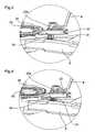
- figure 3shows the chain unit 21 in a first position maintaining the chain 8 on a first sprocket 34
- figure 4shows the chain unit 21 in a second position maintaining the chain 8 on a second sprocket 33.
- the chain unit 21pivots as it is described in the main embodiment around the first apex 22a of the chain member 22.
- the chain unitcan also be translated along an axis passing through the apex 22a and essentially perpendicular to the chain member 22.
- the chain unit 21can then be moved by a traditional gear shifter mounted on the handle bar of the bicycle frame and actuating a cable 31 connected to the chain unit and acting against a spring 32 in a manner well known to the person of ordinary skill in the art.
- the bicycle frame 1can incorporate a number of other elements and features without departing from the intended scope of the invention.
Landscapes
- Engineering & Computer Science (AREA)
- Mechanical Engineering (AREA)
- Chemical & Material Sciences (AREA)
- Combustion & Propulsion (AREA)
- Transportation (AREA)
- Axle Suspensions And Sidecars For Cycles (AREA)
Description
- The present invention relates generally to bicycles especially of the types mountain bike or downhill bike and more particularly to a bicycle frame with a rear suspension system.
- A conventional bicycle frame typically consists of two triangles: a main or front triangle and a paired rear triangle. The front triangle typically includes a top tube and a down tube both connected to a head tube, a seat tube connected to the top tube and a bottom bracket shell connected to the seat tube and the down tube. The rear triangle typically includes a pair of chain stays connecting the bottom bracket shell to the rear axle of a rear wheel and a pair of seat stays connected to the chain stays and to the seat tube.
- A variety of rear wheel suspension systems have been used on bicycle frames to improve performance and rider's comfort.
- In some known rear suspension assemblies, such as the one described in
US 6 361 059 , the rear axle pivots around a single point when subjected to bump or shock forces, as when traversing rough terrain. In these designs, the rear suspension assembly is affected by the pedalling forces which are exerted by the rider and some of the rider's energy is needlessly wasted. - This effect occurs due to the common tendency of rear suspension systems to either lock up or "squat" when the rider pedals. Since most of these systems have a single lever arm which pivots around a single axis, the lock up or squat generally occurs as a result of chain tension acting on the single lever arm. If the single pivot line is above the chain line, the suspension will typically lock up, thereby providing compliance only when the shock or bump forces exceed the chain tension. Conversely, if the single pivot point of the suspension system is below the chain line, the system will typically squat when the rider accelerates, since the chain tension is acting to compress the suspension, similar to a shock or bump force.
- Therefore, there are two constraints in the development of rear suspension systems: on one hand, the centre distance between the bottom bracket shell and the rear axle must be constant over the full wheel travel in order to avoid chain lengthening, and on the other hand, the pivot point of the rear triangle (swing arm) of the bicycle frame must be in line with the upper chain line.
- The more recent rear suspension assemblies, such as the one described in
US 6206397 , present multiple pivot points so that the real pivot point of the rear axle becomes virtual and shifts so as to define a complex curve which is followed by the rear wheel as the suspension is actuated. However, such suspension systems are complicated structures involving a plurality of frame members and joints increasing the manufacturing costs and affecting the stiffness of the bicycle frame. - The
document GB 2 338 216 - The document
WO 2008/025950 discloses a suspension system for a bicycle comprising a rear wheel mounting member, a chassis member, an upper linkage pivotally connected to the rear wheel mounting member and the chassis member at first and second pivot points respectively and a lower linkage pivotally connected to the rear wheel mounting member and the chassis member at third and fourth pivot points respectively thereby forming a four-bar linkage system. The length of the upper linkage between the first and second pivot point and the length of the lower linkage between the third and fourth pivot points are both greater than the separation between the second and fourth pivot points. - It is therefore the object of the present invention to provide a bicycle frame having a rear wheel suspension system which addresses the shortcomings mentioned above.
- The present invention relates to a shock absorbing bicycle frame comprising a front frame unit connected to a bottom bracket shell by which the drive tension is applied to a drive chain, a rear wheel swing arm attached to the front frame unit at a single pivot point and presenting a mounting end to receive a rear axle of a rear wheel, the distance between the said mounting end and the bottom bracket shell being variable over the full rear wheel travel, a rear wheel suspension assembly comprising a compressible shock absorbing unit connecting the rear wheel swing arm to the front frame unit so that to absorb the vertical force applied to the rear axle of a rear wheel due to irregularities of the ground; characterised in that the rear wheel suspension assembly further comprises a chain unit pivotably mounted on the front frame unit, rigidly connected to both the rear wheel swing arm and to the drive chain in order to maintain the drive chain length over the full rear wheel travel and the full variation in the distance between the mounting end of the rear wheel swing arm and the bottom bracket shell, so that the shock absorbing unit is not affected by the pedalling forces due to the rider pedalling, the said pedalling forces being then not wasted
- Other features and advantages of the present invention will become apparent in the following detailed description of one embodiment of the invention, with reference to the accompanying drawings, in which:
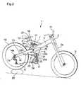
Figure 1 is a side view of the bicycle frame according to the invention in a preferred pedalling position.Figure 2 is a side view of the bicycle frame shown infigure 1 while riding on an irregularity of the ground.Figure 3 is an enlargement of a chain unit of a variant of a bicycle frame according to the invention in a first position.Figure 4 is an enlargement of the chain unit shown infigure 3 in a second position.- Referring to
Figure 1 , abicycle frame 1 according to the present invention generally and preferably comprises ahead tube 2, atop tube 3, aseat tube 4, abottom triangle 5, abottom bracket shell 6 and a rearwheel suspension assembly 20. These elements are typically welded or otherwise secured together to define the frame of the bicycle. - The
head tube 2 extends as usual in an essentially vertical direction and supports a front fork assembly well known to the person of ordinary skill in the art. Theseat tube 4 extends in an essentially vertical direction essentially parallel to thehead tube 2 and supports the rider's mass. Thetop tube 3 extends rearwardly from thehead tube 2 to theseat tube 4. A connectingtube 7 further connects theseat tube 4 to thetop tube 3. - The
bottom triangle 5 connects thetop tube 3 to thebottom bracket shell 6. The saidbottom bracket shell 6 extends in a horizontal direction and receives a conventional crankset (i.e. pedals, crank arm, crank shaft, chain ring(s) and associated components known to the person of ordinary skill in the art, not shown in the drawing) by which the drive tension is applied to thedrive chain 8. As used in this description and the appended claims, the term drive "chain" includes not only bicycle chain but also drive belt, toothed belt and similar power transmission devices. - Although partially shown in the drawings, the person of ordinary skill in the art will understand that the bicycle frame has attachment fittings for the following components:
front wheel 9 andrear wheel 10,handle bars 11 andseat assembly 12. - The rear
wheel suspension assembly 20 generally comprises a rearwheel swing arm 13 pivotably attached to one end of thetop tube 3. In the embodiment of the present invention, the rear wheel swing arm consists of a pair of rear wheel stays 14 which have a firstrear mount end 14a that is adapted for mounting arear axle 15 of therear wheel 10 and which extend forwardly to be pivotably connected to one end of thetop tube 3 at asingle pivot point 30. Preferably, the stays are positioned on either side of therear wheel 10. However, alternative embodiments are possible, such as for example, a single rear wheel stay positioned on only one side of therear wheel 10, - The rear wheel stays 14 may include known elements such as element to secure cables, brake mounts, rear derailleur mounts...
- The
rear suspension assembly 20 further comprises ashock absorbing unit 16 having an elastically deformable damping shock absorber 17. As shown in the drawings, theshock absorber 17 has an adjustable air/oil damping system and an adjustable coil spring, although it is clearly understood to the person of ordinary skill in the art that the shock absorber may be of any suitable type. - The
shock absorbing unit 16 is connected to both the connectingtube 7 and the rearwheel swing arm 13. In this purpose, theshock absorbing unit 16 has afirst push rod 18 which extends upwardly from the rearwheel swing arm 13 and is connected to a first end of alever 26. Thelever 26 is pivotably mounted on theseat tube 4 at apivot point 27 and pivots in an opening 19 of the saidseat tube 4. The other end of thelever 26 is connected to the lower end of the shock absorber 17. - The impact force applied to the bicycle frame when the bicycle is ridden over uneven ground is damped by virtue of deformation of the shock absorber 17.
- The rear
wheel suspension assembly 20 finally comprises achain unit 21. Thechain unit 21 preferably includes an essentiallytriangular chain member 22 pivotably mounted at afirst apex 22a on thebottom triangle 5 of thebicycle frame 1, Thechain unit 21 further comprises asecond push rod 23 which extends downwardly from the rearwheel swing arm 13 and which is mounted to asecond apex 22b of thechain member 22. Thethird apex 22c of thechain member 22 supports anintermediate sprocket 24 for guiding thedrive chain 8. Thechain unit 21 rigidly connects thedrive chain 8 to the rearwheel swing arm 13. In this embodiment, thechain member 22 is pivotably mounted on thebottom triangle 5 in a way that permits thechain drive 8 to pass between the saidbottom triangle 5 and thechain member 22 and to be guided by thesprocket 24. - Having provided a detailed description of the components of the
bicycle frame 1 according to the present invention, the motion which these components cooperate to provide will now be described in detail. - The basic forces which are applied to the rear
wheel suspension assembly 20 are the following: - 1. the mass of the rider which creates a vertically downward force on the
seat tube 4 andbottom bracket shell 6; - 2. the pedal force applied by the rider which creates a vertically downward force and/or torque about the
bottom bracket shell 6 which applies a forward force to therear wheel 10 as result of drive chain tension; - 3. the combined force of the shock absorber 17 (spring and damper) which are upward on the
bicycle frame 1 and downward on therear wheel axle 15; - 4. the vertical ground input (represented by a
rock 25 in the figures) which creates a slightly backward and/or upward force on therear wheel axle 15. This force is represented by an arrow infigure 1 . - The purpose of the invention is to isolate the last force from the first three, that is to isolate the "pedal forces" from the "ground forces", i.e. the
shock absorbing unit 16 will not compress/extend due to pedal forces which are exerted by the rider, but will remain compliant touneven ground 25. - The
rear suspension assembly 20 of the present invention leads to a variation of the distance between thebottom bracket shell 6 and therear wheel axle 15 over the full rear wheel travel. In many prior art suspension, this effect happens indifferently and uncontrollably over the full rear wheel travel and the suspension travel and is therefore undesirable, because it causes the bicycle to "back-pedal" when therear wheel 10 moves vertically due to theuneven ground 25. However, thechain unit 21 of the present invention maintains the chain length over the full rear wheel travel and therefore counteracts the effect due to the variation of the distance between thebottom bracket shell 6 and therear wheel axle 15. - Indeed, without the
chain unit 21, the forward force applied to therear wheel 10 as a result of the chain tension due to the pedal force applied by the rider would actuate/extend theshock absorbing unit 16, which would then be less efficient to accommodate theuneven ground 25. - With the
chain unit 21 according to the invention, the chain tension due to the pedal force applied by the rider exerts a downward force on thechain member 22 of thechain unit 21 which pivots and exerts thus via the second push rod 18 a rearward force to the rearwheel swing arm 13 compensating the forward force to therear wheel 10 due to the chain tension. Theshock absorber 17 is neither compressed nor extended and remains in a state in which it can fully accommodate the uneven ground. - Unlike the bicycle frame of the prior art having a single pivot point rear suspension assembly and an essentially fixed upper chain line, the upper chain line of the bicycle frame according to the invention varies over the full rear wheel travel due to the
chain unit 21. Thepivot point 30 of the rearwheel swing arm 13 according to the present invention is no more required to be in a particular precise position compared to the chain line, such as required in the prior art. Thechain unit 21 prevents as previously mentioned thebicycle frame 1 to squat and theshock absorber 17 to lock up which are common drawbacks of the prior art. In particular and preferably, thepivot point 30 of the rearwheel swing arm 13 is positioned high enough vertically so that an impact pulls in the optimal angle of 90° against the shock absorber 17 (see the angle between the arrow representing the impact force and theswing arm 13 infigure 1 ). - In a variant of the described embodiment illustrated in
figures 3 and 4 , thechain unit 21 can be built to also serve as front derailleur if the bicycle has multiplefront sprockets chain 8 is guided by thechain unit 21 so as to be maintained on the selected sprocket. For example,figure 3 shows thechain unit 21 in a first position maintaining thechain 8 on afirst sprocket 34 andfigure 4 shows thechain unit 21 in a second position maintaining thechain 8 on asecond sprocket 33. Thechain unit 21 pivots as it is described in the main embodiment around the first apex 22a of thechain member 22. In this variant, the chain unit can also be translated along an axis passing through the apex 22a and essentially perpendicular to thechain member 22. Thechain unit 21 can then be moved by a traditional gear shifter mounted on the handle bar of the bicycle frame and actuating acable 31 connected to the chain unit and acting against aspring 32 in a manner well known to the person of ordinary skill in the art. - Persons of ordinary skill in the art will understand that for purposes of this invention, the
bicycle frame 1 can incorporate a number of other elements and features without departing from the intended scope of the invention. - It will also be understood that numerous modifications to and variations on these mechanisms such as the chain unit or the shock absorbing unit will occur to those having ordinary skill in the art and it should be understood that such will fall within the scope of the present invention defined by the appended claims.
- The various components of the invention may be manufactured in a wide variety of ways and from a wide variety of materials, all of which will be readily understood by persons of ordinary skill in the art.
Claims (5)
- A shock absorbing bicycle frame (1) comprising a front frame unit (2, 2a, 3, 4, 5, 7) connected to a bottom bracket shell (6) by which the drive tension is applied to a drive chain (8), a rear wheel swing arm (13) attached to the front frame unit (2, 2a, 3, 4, 5, 7) at a single pivot point (30) and presenting a mounting end (14a) to receive a rear axle (15) of a rear wheel (10), the distance between the said mounting end (14a) and the bottom bracket shell (6) being variable over the full rear wheel travel, a rear wheel suspension assembly (20) comprising a compressible shock absorbing unit (16) connecting the rear wheel swing arm (13) to the front frame unit (2, 2a, 3, 4, 5, 7) so that to absorb the vertical force applied to the rear axle (15) of a rear wheel (10) due to irregularities (25) of the ground;characterised in that the rear wheel suspension assembly (20) further comprises a chain unit (21) pivotably mounted on the front frame unit (2, 2a, 3, 4, 5, 7), rigidly connected to both the rear wheel swing arm (13) and to the drive chain (8) in order to maintain the drive chain length over the full rear wheel travel and the full variation in the distance between the mounting end (14a) of the rear wheel swing arm (13) and the bottom bracket shell (6), so that the shock absorbing unit (16) is not affected by the pedalling forces due to the rider pedalling, the said pedalling forces being then not wasted.
- Shock absorbing bicycle frame according to claim 1,characterised in that the chain unit (21) comprises an essentially triangular chain member (22) pivotably mounted at a first apex (22a) on the front frame unit (2, 2a, 3, 4, 5, 7), a push rod (23) extending from the rear wheel swing arm (13) and mounted to a second apex (22b) of the chain member (22) and a sprocket (24) pivotably mounted on a third apex (22c) of the chain member (22) and guiding the drive chain (8).
- Shock absorbing bicycle frame according to any one of claims 1 and 2,characterised in that the pivot point (30) of the rear wheel swing arm (13) and the shock absorbing unit (16) are positioned so that an impact on the frame due to irregularities (25) of the ground exerts a perpendicular force on the said shock absorbing unit (16).
- Shock absorbing bicycle frame according to any one of claims 1 and 2,characterised in that the chain unit (21) comprises a chain member (22) pivotably mounted on the front frame unit (2, 2a, 3, 4, 5, 7), a push rod (23) rigidly connecting the chain member (22) to the rear wheel swing arm (13) and a sprocket (24) mounted on the chain member (22) and guiding the drive chain (8)
- Shock absorbing bicycle frame according to any one of the preceding claims,characterised in that the chain unit (21) further serves as a front derailleur.
Priority Applications (2)
| Application Number | Priority Date | Filing Date | Title |
|---|---|---|---|
| EP10008516.6AEP2420435B1 (en) | 2010-08-16 | 2010-08-16 | Bicycle frame with rear suspension system |
| US13/198,875US8434776B2 (en) | 2010-08-16 | 2011-08-05 | Bicycle frame with rear suspension system |
Applications Claiming Priority (1)
| Application Number | Priority Date | Filing Date | Title |
|---|---|---|---|
| EP10008516.6AEP2420435B1 (en) | 2010-08-16 | 2010-08-16 | Bicycle frame with rear suspension system |
Publications (2)
| Publication Number | Publication Date |
|---|---|
| EP2420435A1 EP2420435A1 (en) | 2012-02-22 |
| EP2420435B1true EP2420435B1 (en) | 2013-10-30 |
Family
ID=43333244
Family Applications (1)
| Application Number | Title | Priority Date | Filing Date |
|---|---|---|---|
| EP10008516.6AActiveEP2420435B1 (en) | 2010-08-16 | 2010-08-16 | Bicycle frame with rear suspension system |
Country Status (2)
| Country | Link |
|---|---|
| US (1) | US8434776B2 (en) |
| EP (1) | EP2420435B1 (en) |
Families Citing this family (22)
| Publication number | Priority date | Publication date | Assignee | Title |
|---|---|---|---|---|
| WO2006032052A2 (en) | 2004-09-15 | 2006-03-23 | Yeti Cycling, Llc | Rear suspension system for a bicycle |
| US9821879B2 (en) | 2010-08-20 | 2017-11-21 | Yeti Cycling, Llc | Reciprocating rail movement suspension system |
| EP2605953B1 (en) | 2010-08-20 | 2021-06-16 | Yeti Cycling LLC | Link suspension system |
| US9359034B2 (en)* | 2012-01-12 | 2016-06-07 | Recreation Systems, Inc. | Cycle and associated components |
| US9249867B2 (en)* | 2012-02-20 | 2016-02-02 | Gamut Usa | Retention mechanisms for bicycle drive trains |
| DE102012017647A1 (en)* | 2012-09-06 | 2014-05-15 | Winora-Staiger Gmbh | Bicycle, especially mountain bike, with an electric drive |
| US10766563B2 (en) | 2013-01-16 | 2020-09-08 | Yeti Cyclying, Llc | Rail suspension with integral shock and dampening mechanism |
| US9187148B2 (en) | 2013-04-29 | 2015-11-17 | Huffy Corporation | Drive system for a pedaled vehicle |
| US9156521B2 (en) | 2013-12-23 | 2015-10-13 | Wayne Lumpkin | Bicycle frame rear suspension with flexing frame segment |
| DE102016205540B3 (en)* | 2016-04-04 | 2017-09-28 | QCS Quality Consult Service GmbH | DRIVE DEVICE FOR AN ELECTRIC MOTORIZED BICYCLE |
| CN106741555A (en)* | 2016-12-31 | 2017-05-31 | 天津顺兴捷科技有限责任公司 | A kind of quick multi-speed bicycle |
| EP3595963A4 (en) | 2017-03-17 | 2021-03-10 | Yeti Cycling, LLC | Vehicle suspension linkage |
| EP3649040A4 (en) | 2017-07-07 | 2021-03-10 | Yeti Cycling, LLC | VEHICLE SUSPENSION LINK |
| US12077241B2 (en) | 2019-02-01 | 2024-09-03 | Yeti Cycling, Llc | Multi-body vehicle suspension linkage |
| US12145684B2 (en) | 2019-12-24 | 2024-11-19 | Yeti Cycling, Llc | Constrained multiple instantaneous velocity center linkage assembly for vehicle suspension |
| DE102021104753A1 (en) | 2020-02-28 | 2021-09-02 | Yeti Cycling, Llc | Vehicle suspension link assembly with six beams and a driveline freewheel |
| WO2021257865A1 (en)* | 2020-06-17 | 2021-12-23 | Unified Bikes, Llc | Drive side idler sprocket system for controlling chainline |
| US12384484B2 (en) | 2020-11-18 | 2025-08-12 | Yeti Cycling, Llc | Integrated motor mount and suspension pivot |
| US20220297795A1 (en)* | 2021-03-19 | 2022-09-22 | David Weagle | Sequential adjacent drive assembly for a cycle |
| GB2605244B (en)* | 2021-12-29 | 2023-04-26 | James Everitt Simon | Squat-or-anti-squat-characteristic-adjustable two-wheeled vehicle |
| GB2611590C (en) | 2022-02-17 | 2024-01-31 | Inspiral Cycles Ltd | A frame for a bicycle |
| DE102024202125A1 (en)* | 2024-03-07 | 2025-09-11 | Zf Friedrichshafen Ag | Clamping system and bicycle |
Family Cites Families (12)
| Publication number | Priority date | Publication date | Assignee | Title |
|---|---|---|---|---|
| US2976056A (en)* | 1958-06-04 | 1961-03-21 | John D Henry | Bicycle suspension system |
| US4069719A (en)* | 1976-06-18 | 1978-01-24 | Cancilla Philip S | Chain tensioner for chain drives |
| US6206397B1 (en) | 1995-01-25 | 2001-03-27 | James B. Klassen | Bicycle wheel travel path for selectively applying chainstay lengthening effect and apparatus for providing same |
| US6079726A (en)* | 1997-05-13 | 2000-06-27 | Gt Bicycles, Inc. | Direct drive bicycle |
| GB2338216A (en)* | 1998-05-22 | 1999-12-15 | Bike Technology Dev Limited | Bicycle with articulating rear wheel |
| US6361059B1 (en) | 1999-09-10 | 2002-03-26 | Anthony S. Ellsworth | Single pivot bicycle suspension apparatus and related methods |
| JP4115249B2 (en)* | 2002-11-05 | 2008-07-09 | 本田技研工業株式会社 | bicycle |
| TWI283219B (en)* | 2004-02-10 | 2007-07-01 | Honda Motor Co Ltd | Chain tension structure |
| NZ531898A (en)* | 2004-03-23 | 2006-01-27 | David Evans | Cycle suspension assembly |
| JP4530783B2 (en)* | 2004-09-29 | 2010-08-25 | 本田技研工業株式会社 | Torque transmission mechanism with one-way clutch and slide mechanism |
| TW200801513A (en) | 2006-06-29 | 2008-01-01 | Fermiscan Australia Pty Ltd | Improved process |
| GB0617086D0 (en)* | 2006-08-30 | 2006-10-11 | K9 Ind Ltd | Bicycle suspension |
- 2010
- 2010-08-16EPEP10008516.6Apatent/EP2420435B1/enactiveActive
- 2011
- 2011-08-05USUS13/198,875patent/US8434776B2/ennot_activeExpired - Fee Related
Also Published As
| Publication number | Publication date |
|---|---|
| US8434776B2 (en) | 2013-05-07 |
| US20120038130A1 (en) | 2012-02-16 |
| EP2420435A1 (en) | 2012-02-22 |
Similar Documents
| Publication | Publication Date | Title |
|---|---|---|
| EP2420435B1 (en) | Bicycle frame with rear suspension system | |
| EP2969726B1 (en) | Bicycle rear suspension | |
| US7909347B2 (en) | Bicycle suspension system employing highly predictable pedalling characteristics | |
| EP3261908B1 (en) | Rear suspension system for a bicycle | |
| EP2061693B1 (en) | Bicycle suspension | |
| US5899480A (en) | Rear suspension for bicycles | |
| CA2424428C (en) | Rear suspension system for two-wheeled vehicles, particularly bicycles | |
| EP2828144B1 (en) | Bicycle rear suspension system | |
| US7934739B2 (en) | Bicycle rear suspension | |
| EP1698549B1 (en) | Bicycle with rear suspension | |
| US9845132B2 (en) | Mountain bicycle with rear suspension having neutral braking trajectory | |
| US7066481B1 (en) | Bicycle rear suspension | |
| US20040061305A1 (en) | Rear wheel suspension system for a bicycle | |
| US10377442B2 (en) | Suspension for a bicycle | |
| US7296815B2 (en) | Bicycle suspension apparatus and related method | |
| EP0621840A1 (en) | Rear suspension for bicycles | |
| US6837506B2 (en) | Bicycle frame | |
| AU2016102059A4 (en) | Suspension for a bicycle | |
| US20230115232A1 (en) | Rear suspension system for bicycles | |
| GB2475394A (en) | Rear suspension unit for use with folding bicycle |
Legal Events
| Date | Code | Title | Description |
|---|---|---|---|
| AK | Designated contracting states | Kind code of ref document:A1 Designated state(s):AL AT BE BG CH CY CZ DE DK EE ES FI FR GB GR HR HU IE IS IT LI LT LU LV MC MK MT NL NO PL PT RO SE SI SK SM TR | |
| AX | Request for extension of the european patent | Extension state:BA ME RS | |
| PUAI | Public reference made under article 153(3) epc to a published international application that has entered the european phase | Free format text:ORIGINAL CODE: 0009012 | |
| 17P | Request for examination filed | Effective date:20120815 | |
| GRAP | Despatch of communication of intention to grant a patent | Free format text:ORIGINAL CODE: EPIDOSNIGR1 | |
| INTG | Intention to grant announced | Effective date:20130517 | |
| GRAS | Grant fee paid | Free format text:ORIGINAL CODE: EPIDOSNIGR3 | |
| GRAA | (expected) grant | Free format text:ORIGINAL CODE: 0009210 | |
| AK | Designated contracting states | Kind code of ref document:B1 Designated state(s):AL AT BE BG CH CY CZ DE DK EE ES FI FR GB GR HR HU IE IS IT LI LT LU LV MC MK MT NL NO PL PT RO SE SI SK SM TR | |
| REG | Reference to a national code | Ref country code:GB Ref legal event code:FG4D | |
| REG | Reference to a national code | Ref country code:CH Ref legal event code:EP | |
| REG | Reference to a national code | Ref country code:AT Ref legal event code:REF Ref document number:638399 Country of ref document:AT Kind code of ref document:T Effective date:20131115 | |
| REG | Reference to a national code | Ref country code:IE Ref legal event code:FG4D | |
| REG | Reference to a national code | Ref country code:DE Ref legal event code:R096 Ref document number:602010011279 Country of ref document:DE Effective date:20131224 | |
| REG | Reference to a national code | Ref country code:NL Ref legal event code:VDEP Effective date:20131030 | |
| REG | Reference to a national code | Ref country code:AT Ref legal event code:MK05 Ref document number:638399 Country of ref document:AT Kind code of ref document:T Effective date:20131030 | |
| REG | Reference to a national code | Ref country code:LT Ref legal event code:MG4D | |
| PG25 | Lapsed in a contracting state [announced via postgrant information from national office to epo] | Ref country code:FI Free format text:LAPSE BECAUSE OF FAILURE TO SUBMIT A TRANSLATION OF THE DESCRIPTION OR TO PAY THE FEE WITHIN THE PRESCRIBED TIME-LIMIT Effective date:20131030 Ref country code:HR Free format text:LAPSE BECAUSE OF FAILURE TO SUBMIT A TRANSLATION OF THE DESCRIPTION OR TO PAY THE FEE WITHIN THE PRESCRIBED TIME-LIMIT Effective date:20131030 Ref country code:NO Free format text:LAPSE BECAUSE OF FAILURE TO SUBMIT A TRANSLATION OF THE DESCRIPTION OR TO PAY THE FEE WITHIN THE PRESCRIBED TIME-LIMIT Effective date:20140130 Ref country code:BE Free format text:LAPSE BECAUSE OF FAILURE TO SUBMIT A TRANSLATION OF THE DESCRIPTION OR TO PAY THE FEE WITHIN THE PRESCRIBED TIME-LIMIT Effective date:20131030 Ref country code:SE Free format text:LAPSE BECAUSE OF FAILURE TO SUBMIT A TRANSLATION OF THE DESCRIPTION OR TO PAY THE FEE WITHIN THE PRESCRIBED TIME-LIMIT Effective date:20131030 Ref country code:NL Free format text:LAPSE BECAUSE OF FAILURE TO SUBMIT A TRANSLATION OF THE DESCRIPTION OR TO PAY THE FEE WITHIN THE PRESCRIBED TIME-LIMIT Effective date:20131030 Ref country code:LT Free format text:LAPSE BECAUSE OF FAILURE TO SUBMIT A TRANSLATION OF THE DESCRIPTION OR TO PAY THE FEE WITHIN THE PRESCRIBED TIME-LIMIT Effective date:20131030 Ref country code:IS Free format text:LAPSE BECAUSE OF FAILURE TO SUBMIT A TRANSLATION OF THE DESCRIPTION OR TO PAY THE FEE WITHIN THE PRESCRIBED TIME-LIMIT Effective date:20140228 | |
| PG25 | Lapsed in a contracting state [announced via postgrant information from national office to epo] | Ref country code:ES Free format text:LAPSE BECAUSE OF FAILURE TO SUBMIT A TRANSLATION OF THE DESCRIPTION OR TO PAY THE FEE WITHIN THE PRESCRIBED TIME-LIMIT Effective date:20131030 Ref country code:LV Free format text:LAPSE BECAUSE OF FAILURE TO SUBMIT A TRANSLATION OF THE DESCRIPTION OR TO PAY THE FEE WITHIN THE PRESCRIBED TIME-LIMIT Effective date:20131030 Ref country code:AT Free format text:LAPSE BECAUSE OF FAILURE TO SUBMIT A TRANSLATION OF THE DESCRIPTION OR TO PAY THE FEE WITHIN THE PRESCRIBED TIME-LIMIT Effective date:20131030 Ref country code:CY Free format text:LAPSE BECAUSE OF FAILURE TO SUBMIT A TRANSLATION OF THE DESCRIPTION OR TO PAY THE FEE WITHIN THE PRESCRIBED TIME-LIMIT Effective date:20131030 | |
| PG25 | Lapsed in a contracting state [announced via postgrant information from national office to epo] | Ref country code:PT Free format text:LAPSE BECAUSE OF FAILURE TO SUBMIT A TRANSLATION OF THE DESCRIPTION OR TO PAY THE FEE WITHIN THE PRESCRIBED TIME-LIMIT Effective date:20140228 | |
| PG25 | Lapsed in a contracting state [announced via postgrant information from national office to epo] | Ref country code:EE Free format text:LAPSE BECAUSE OF FAILURE TO SUBMIT A TRANSLATION OF THE DESCRIPTION OR TO PAY THE FEE WITHIN THE PRESCRIBED TIME-LIMIT Effective date:20131030 | |
| REG | Reference to a national code | Ref country code:DE Ref legal event code:R097 Ref document number:602010011279 Country of ref document:DE | |
| PG25 | Lapsed in a contracting state [announced via postgrant information from national office to epo] | Ref country code:RO Free format text:LAPSE BECAUSE OF FAILURE TO SUBMIT A TRANSLATION OF THE DESCRIPTION OR TO PAY THE FEE WITHIN THE PRESCRIBED TIME-LIMIT Effective date:20131030 Ref country code:SK Free format text:LAPSE BECAUSE OF FAILURE TO SUBMIT A TRANSLATION OF THE DESCRIPTION OR TO PAY THE FEE WITHIN THE PRESCRIBED TIME-LIMIT Effective date:20131030 Ref country code:PL Free format text:LAPSE BECAUSE OF FAILURE TO SUBMIT A TRANSLATION OF THE DESCRIPTION OR TO PAY THE FEE WITHIN THE PRESCRIBED TIME-LIMIT Effective date:20131030 Ref country code:CZ Free format text:LAPSE BECAUSE OF FAILURE TO SUBMIT A TRANSLATION OF THE DESCRIPTION OR TO PAY THE FEE WITHIN THE PRESCRIBED TIME-LIMIT Effective date:20131030 Ref country code:IT Free format text:LAPSE BECAUSE OF FAILURE TO SUBMIT A TRANSLATION OF THE DESCRIPTION OR TO PAY THE FEE WITHIN THE PRESCRIBED TIME-LIMIT Effective date:20131030 | |
| PLBE | No opposition filed within time limit | Free format text:ORIGINAL CODE: 0009261 | |
| STAA | Information on the status of an ep patent application or granted ep patent | Free format text:STATUS: NO OPPOSITION FILED WITHIN TIME LIMIT | |
| PG25 | Lapsed in a contracting state [announced via postgrant information from national office to epo] | Ref country code:DK Free format text:LAPSE BECAUSE OF FAILURE TO SUBMIT A TRANSLATION OF THE DESCRIPTION OR TO PAY THE FEE WITHIN THE PRESCRIBED TIME-LIMIT Effective date:20131030 | |
| 26N | No opposition filed | Effective date:20140731 | |
| REG | Reference to a national code | Ref country code:DE Ref legal event code:R097 Ref document number:602010011279 Country of ref document:DE Effective date:20140731 | |
| PG25 | Lapsed in a contracting state [announced via postgrant information from national office to epo] | Ref country code:SI Free format text:LAPSE BECAUSE OF FAILURE TO SUBMIT A TRANSLATION OF THE DESCRIPTION OR TO PAY THE FEE WITHIN THE PRESCRIBED TIME-LIMIT Effective date:20131030 | |
| PG25 | Lapsed in a contracting state [announced via postgrant information from national office to epo] | Ref country code:MC Free format text:LAPSE BECAUSE OF FAILURE TO SUBMIT A TRANSLATION OF THE DESCRIPTION OR TO PAY THE FEE WITHIN THE PRESCRIBED TIME-LIMIT Effective date:20131030 Ref country code:LU Free format text:LAPSE BECAUSE OF FAILURE TO SUBMIT A TRANSLATION OF THE DESCRIPTION OR TO PAY THE FEE WITHIN THE PRESCRIBED TIME-LIMIT Effective date:20140816 | |
| REG | Reference to a national code | Ref country code:CH Ref legal event code:PL | |
| GBPC | Gb: european patent ceased through non-payment of renewal fee | Effective date:20140816 | |
| PG25 | Lapsed in a contracting state [announced via postgrant information from national office to epo] | Ref country code:CH Free format text:LAPSE BECAUSE OF NON-PAYMENT OF DUE FEES Effective date:20140831 Ref country code:LI Free format text:LAPSE BECAUSE OF NON-PAYMENT OF DUE FEES Effective date:20140831 | |
| REG | Reference to a national code | Ref country code:CH Ref legal event code:AECN Free format text:DAS PATENT IST AUFGRUND DES WEITERBEHANDLUNGSANTRAGS VOM 11. MAI 2015 REAKTIVIERT WORDEN. | |
| REG | Reference to a national code | Ref country code:IE Ref legal event code:MM4A | |
| PG25 | Lapsed in a contracting state [announced via postgrant information from national office to epo] | Ref country code:GB Free format text:LAPSE BECAUSE OF NON-PAYMENT OF DUE FEES Effective date:20140816 | |
| PGRI | Patent reinstated in contracting state [announced from national office to epo] | Ref country code:LI Effective date:20150512 Ref country code:CH Effective date:20150512 | |
| REG | Reference to a national code | Ref country code:FR Ref legal event code:PLFP Year of fee payment:6 | |
| PG25 | Lapsed in a contracting state [announced via postgrant information from national office to epo] | Ref country code:IE Free format text:LAPSE BECAUSE OF NON-PAYMENT OF DUE FEES Effective date:20140816 | |
| PGFP | Annual fee paid to national office [announced via postgrant information from national office to epo] | Ref country code:FR Payment date:20150824 Year of fee payment:6 | |
| PGFP | Annual fee paid to national office [announced via postgrant information from national office to epo] | Ref country code:CH Payment date:20151118 Year of fee payment:6 | |
| REG | Reference to a national code | Ref country code:GB Ref legal event code:S28 Free format text:APPLICATION FILED | |
| PG25 | Lapsed in a contracting state [announced via postgrant information from national office to epo] | Ref country code:SM Free format text:LAPSE BECAUSE OF FAILURE TO SUBMIT A TRANSLATION OF THE DESCRIPTION OR TO PAY THE FEE WITHIN THE PRESCRIBED TIME-LIMIT Effective date:20131030 | |
| PGFP | Annual fee paid to national office [announced via postgrant information from national office to epo] | Ref country code:DE Payment date:20160215 Year of fee payment:6 | |
| PG25 | Lapsed in a contracting state [announced via postgrant information from national office to epo] | Ref country code:GR Free format text:LAPSE BECAUSE OF FAILURE TO SUBMIT A TRANSLATION OF THE DESCRIPTION OR TO PAY THE FEE WITHIN THE PRESCRIBED TIME-LIMIT Effective date:20140131 Ref country code:MT Free format text:LAPSE BECAUSE OF FAILURE TO SUBMIT A TRANSLATION OF THE DESCRIPTION OR TO PAY THE FEE WITHIN THE PRESCRIBED TIME-LIMIT Effective date:20131030 Ref country code:BG Free format text:LAPSE BECAUSE OF FAILURE TO SUBMIT A TRANSLATION OF THE DESCRIPTION OR TO PAY THE FEE WITHIN THE PRESCRIBED TIME-LIMIT Effective date:20131030 | |
| PG25 | Lapsed in a contracting state [announced via postgrant information from national office to epo] | Ref country code:TR Free format text:LAPSE BECAUSE OF FAILURE TO SUBMIT A TRANSLATION OF THE DESCRIPTION OR TO PAY THE FEE WITHIN THE PRESCRIBED TIME-LIMIT Effective date:20131030 Ref country code:HU Free format text:LAPSE BECAUSE OF FAILURE TO SUBMIT A TRANSLATION OF THE DESCRIPTION OR TO PAY THE FEE WITHIN THE PRESCRIBED TIME-LIMIT; INVALID AB INITIO Effective date:20100816 | |
| REG | Reference to a national code | Ref country code:GB Ref legal event code:S28 Free format text:APPLICATION WITHDRAWN Effective date:20161110 | |
| REG | Reference to a national code | Ref country code:DE Ref legal event code:R119 Ref document number:602010011279 Country of ref document:DE | |
| REG | Reference to a national code | Ref country code:CH Ref legal event code:PL | |
| PG25 | Lapsed in a contracting state [announced via postgrant information from national office to epo] | Ref country code:LI Free format text:LAPSE BECAUSE OF NON-PAYMENT OF DUE FEES Effective date:20160831 Ref country code:CH Free format text:LAPSE BECAUSE OF NON-PAYMENT OF DUE FEES Effective date:20160831 | |
| REG | Reference to a national code | Ref country code:FR Ref legal event code:ST Effective date:20170428 | |
| PG25 | Lapsed in a contracting state [announced via postgrant information from national office to epo] | Ref country code:FR Free format text:LAPSE BECAUSE OF NON-PAYMENT OF DUE FEES Effective date:20160831 Ref country code:DE Free format text:LAPSE BECAUSE OF NON-PAYMENT OF DUE FEES Effective date:20170301 | |
| PG25 | Lapsed in a contracting state [announced via postgrant information from national office to epo] | Ref country code:MK Free format text:LAPSE BECAUSE OF FAILURE TO SUBMIT A TRANSLATION OF THE DESCRIPTION OR TO PAY THE FEE WITHIN THE PRESCRIBED TIME-LIMIT Effective date:20131030 | |
| PG25 | Lapsed in a contracting state [announced via postgrant information from national office to epo] | Ref country code:AL Free format text:LAPSE BECAUSE OF FAILURE TO SUBMIT A TRANSLATION OF THE DESCRIPTION OR TO PAY THE FEE WITHIN THE PRESCRIBED TIME-LIMIT Effective date:20131030 |