EP2419849B1 - Clinical decision support systems and methods - Google Patents
Clinical decision support systems and methodsDownload PDFInfo
- Publication number
- EP2419849B1 EP2419849B1EP10719078.7AEP10719078AEP2419849B1EP 2419849 B1EP2419849 B1EP 2419849B1EP 10719078 AEP10719078 AEP 10719078AEP 2419849 B1EP2419849 B1EP 2419849B1
- Authority
- EP
- European Patent Office
- Prior art keywords
- patient
- cds
- case
- features
- probative
- Prior art date
- Legal status (The legal status is an assumption and is not a legal conclusion. Google has not performed a legal analysis and makes no representation as to the accuracy of the status listed.)
- Active
Links
- 238000000034methodMethods0.000titleclaimsdescription44
- 238000010801machine learningMethods0.000claimsdescription28
- 238000000605extractionMethods0.000claimsdescription12
- 230000006870functionEffects0.000claimsdescription8
- 230000008569processEffects0.000claimsdescription6
- 238000002591computed tomographyMethods0.000claimsdescription5
- 230000000007visual effectEffects0.000claimsdescription5
- 238000002594fluoroscopyMethods0.000claimsdescription3
- 238000002603single-photon emission computed tomographyMethods0.000claimsdescription3
- 238000002604ultrasonographyMethods0.000claimsdescription3
- 238000002600positron emission tomographyMethods0.000claimsdescription2
- 238000003384imaging methodMethods0.000description23
- 230000002068genetic effectEffects0.000description18
- 206010006187Breast cancerDiseases0.000description15
- 208000026310Breast neoplasmDiseases0.000description15
- 206010028980NeoplasmDiseases0.000description15
- 210000000349chromosomeAnatomy0.000description14
- 108090000623proteins and genesProteins0.000description14
- 238000003745diagnosisMethods0.000description9
- 238000013459approachMethods0.000description8
- 210000000481breastAnatomy0.000description8
- 230000005856abnormalityEffects0.000description7
- 238000004458analytical methodMethods0.000description7
- 238000012545processingMethods0.000description6
- 230000008901benefitEffects0.000description4
- 230000001149cognitive effectEffects0.000description4
- 230000000875corresponding effectEffects0.000description4
- 238000013535dynamic contrast enhanced MRIMethods0.000description4
- 238000012552reviewMethods0.000description4
- 238000010200validation analysisMethods0.000description4
- 230000009471actionEffects0.000description3
- 238000001574biopsyMethods0.000description3
- 201000011510cancerDiseases0.000description3
- 239000002872contrast mediaSubstances0.000description3
- 238000002595magnetic resonance imagingMethods0.000description3
- 230000004075alterationEffects0.000description2
- 230000003190augmentative effectEffects0.000description2
- 230000002146bilateral effectEffects0.000description2
- 230000000747cardiac effectEffects0.000description2
- 230000008859changeEffects0.000description2
- 238000002059diagnostic imagingMethods0.000description2
- 230000003902lesionEffects0.000description2
- 230000007246mechanismEffects0.000description2
- 238000012986modificationMethods0.000description2
- 230000004048modificationEffects0.000description2
- 230000000877morphologic effectEffects0.000description2
- 230000008447perceptionEffects0.000description2
- 230000002085persistent effectEffects0.000description2
- 230000009467reductionEffects0.000description2
- 238000012549trainingMethods0.000description2
- 238000011282treatmentMethods0.000description2
- 238000012285ultrasound imagingMethods0.000description2
- 229910000497AmalgamInorganic materials0.000description1
- 108700020463BRCA1Proteins0.000description1
- 102000036365BRCA1Human genes0.000description1
- 101150072950BRCA1 geneProteins0.000description1
- 108700020462BRCA2Proteins0.000description1
- 102000052609BRCA2Human genes0.000description1
- 208000003174Brain NeoplasmsDiseases0.000description1
- 101150008921Brca2 geneProteins0.000description1
- 206010064571Gene mutationDiseases0.000description1
- 206010027476MetastasesDiseases0.000description1
- 238000012879PET imagingMethods0.000description1
- 230000003416augmentationEffects0.000description1
- 230000036772blood pressureEffects0.000description1
- 231100000504carcinogenesisToxicity0.000description1
- 230000001413cellular effectEffects0.000description1
- 238000012512characterization methodMethods0.000description1
- 238000003759clinical diagnosisMethods0.000description1
- 210000001072colonAnatomy0.000description1
- 238000004891communicationMethods0.000description1
- 238000013170computed tomography imagingMethods0.000description1
- 238000004590computer programMethods0.000description1
- 238000010276constructionMethods0.000description1
- 230000008094contradictory effectEffects0.000description1
- 230000002596correlated effectEffects0.000description1
- 230000001934delayEffects0.000description1
- 238000009795derivationMethods0.000description1
- 230000000694effectsEffects0.000description1
- 230000001747exhibiting effectEffects0.000description1
- 239000000284extractSubstances0.000description1
- 238000010191image analysisMethods0.000description1
- 230000003993interactionEffects0.000description1
- 230000002452interceptive effectEffects0.000description1
- 210000004185liverAnatomy0.000description1
- 210000004072lungAnatomy0.000description1
- 230000003211malignant effectEffects0.000description1
- 238000009607mammographyMethods0.000description1
- 230000013011matingEffects0.000description1
- 238000005259measurementMethods0.000description1
- 238000010339medical testMethods0.000description1
- 230000009401metastasisEffects0.000description1
- 230000003278mimic effectEffects0.000description1
- 230000035772mutationEffects0.000description1
- 230000003287optical effectEffects0.000description1
- 238000005457optimizationMethods0.000description1
- 238000004091panningMethods0.000description1
- 230000000717retained effectEffects0.000description1
- 238000005070samplingMethods0.000description1
- 230000035945sensitivityEffects0.000description1
- 238000002922simulated annealingMethods0.000description1
- 238000012360testing methodMethods0.000description1
- 210000001519tissueAnatomy0.000description1
- 238000011269treatment regimenMethods0.000description1
Images


Classifications
- G—PHYSICS
- G16—INFORMATION AND COMMUNICATION TECHNOLOGY [ICT] SPECIALLY ADAPTED FOR SPECIFIC APPLICATION FIELDS
- G16H—HEALTHCARE INFORMATICS, i.e. INFORMATION AND COMMUNICATION TECHNOLOGY [ICT] SPECIALLY ADAPTED FOR THE HANDLING OR PROCESSING OF MEDICAL OR HEALTHCARE DATA
- G16H30/00—ICT specially adapted for the handling or processing of medical images
- G16H30/20—ICT specially adapted for the handling or processing of medical images for handling medical images, e.g. DICOM, HL7 or PACS
- G—PHYSICS
- G16—INFORMATION AND COMMUNICATION TECHNOLOGY [ICT] SPECIALLY ADAPTED FOR SPECIFIC APPLICATION FIELDS
- G16H—HEALTHCARE INFORMATICS, i.e. INFORMATION AND COMMUNICATION TECHNOLOGY [ICT] SPECIALLY ADAPTED FOR THE HANDLING OR PROCESSING OF MEDICAL OR HEALTHCARE DATA
- G16H40/00—ICT specially adapted for the management or administration of healthcare resources or facilities; ICT specially adapted for the management or operation of medical equipment or devices
- G16H40/60—ICT specially adapted for the management or administration of healthcare resources or facilities; ICT specially adapted for the management or operation of medical equipment or devices for the operation of medical equipment or devices
- G16H40/63—ICT specially adapted for the management or administration of healthcare resources or facilities; ICT specially adapted for the management or operation of medical equipment or devices for the operation of medical equipment or devices for local operation
- G—PHYSICS
- G16—INFORMATION AND COMMUNICATION TECHNOLOGY [ICT] SPECIALLY ADAPTED FOR SPECIFIC APPLICATION FIELDS
- G16H—HEALTHCARE INFORMATICS, i.e. INFORMATION AND COMMUNICATION TECHNOLOGY [ICT] SPECIALLY ADAPTED FOR THE HANDLING OR PROCESSING OF MEDICAL OR HEALTHCARE DATA
- G16H50/00—ICT specially adapted for medical diagnosis, medical simulation or medical data mining; ICT specially adapted for detecting, monitoring or modelling epidemics or pandemics
- G16H50/20—ICT specially adapted for medical diagnosis, medical simulation or medical data mining; ICT specially adapted for detecting, monitoring or modelling epidemics or pandemics for computer-aided diagnosis, e.g. based on medical expert systems
Definitions
- the followingrelates to the medical arts, medical diagnostic arts, medical case management arts, expert system arts, and related arts.
- Clinical decision support (CDS) systemsare expert systems constructed to provide automated assistance to physicians or other medical personnel in making medical decisions such as ailment diagnosis, treatment selection, implementation of aspects of a treatment regimen, and so forth. Some illustrative CDS systems are described, for example, in Alsafadi, U.S. Publ. Appl. No. 2007/0175980 A1 .
- case results from a physician's own experienceguide the physician's decisions regarding new clinical situations.
- a case-based CDS systemattempts to emulate this approach by facilitating automated access to a voluminous set of past cases that exceeds the historical experience possessed by any single physician.
- a case-based CDS systemcan provide decision support for diagnosing an abnormality found in breast cancer studies of a patient by retrieving test results and other relevant information from past patient cases (with the patient data suitably anonymized to comply with patient privacy regulations or standards).
- Such case-based CDS systemsemulate clinical decision-making thought processes that are generally accepted as proper in the medical arts.
- the CDS systemoperates as an information retrieval system which retrieves similar past medical cases, and may also retrieve or particularly identify relevant medical test results or other case information that is likely to be probative for a present diagnosis or other present medical decision.
- machine learning approacheshave also been used in information retrieval systems in order to automatically group similar objects based on automated analysis of object features. Again, however, machine learning does not readily provide information as to the basis by which similarity or dissimilarity is assessed.
- the machine learned algorithmis a "black box" that may be suitable for applications such as image retrieval - but, a physician or other medical person is unlikely to be comfortable with making a medical diagnosis or other medical decision on an empirical basis without understanding the underlying decision-making rationale.
- Relevance feedback techniquesare also known. In these techniques, human-performed or other authoritative analysis is applied to information retrieval results to assess the actual relevance of the retrieved information. These authoritative assessments are used to refine the information retrieval algorithm in the hope of improving subsequent retrieval operations.
- a difficulty with relevance feedback in the CDS contextis that feedback over time is likely to come from different physicians, potentially resulting in differing or contradictory relevance feedback. Additionally, relevance feedback requires time to assess the retrieved results and provide the feedback, which a busy physician may be unwilling to do. Still further, relevance feedback only provides refinement for an existing information retrieval system and does not provide a basis for constructing a CDS system ab initio.
- a clinical decision support (CDS) systemcomprises: a case grouping sub-system including a graphical user interface that is operative to simultaneously display data representing a plurality of patient cases and further configured to enable a user to group selected patient cases represented by the simultaneously displayed data into clinically related groups as selected by the user; a probative features determination sub-system that is operative to determine probative features that correlate with the clinically related groups; and a CDS user interface that is operative to receive current patient data relating to a current patient case and to output clinical decision support information based on values of the probative features determined from the received current patient data.
- a storage mediumstoring instructions executable by a digital processor to perform the clinical decision support (CDS) method set forth in the immediately preceding paragraph.
- CDSclinical decision support
- One advantageresides in providing patient case groupings determined holistically by a physician or other skilled medical person in order to establish similarity ground truth information for CDS operation.
- Another advantageresides in providing a user interface for manual grouping of similar patient cases in which the patient cases are represented by patient icons comprising patient images or thumbnail images generated from patient images.
- Another advantageresides in automatically determining image and optionally non-image features correlating with similarity ground truth information.
- the present disclosurerecognizes that the CDS system operation can be divided into two parts: (i) clustering of similar patient cases in order to identify a similarity "ground truth" (defined below at the end of the next paragraph); and (ii) the identification of probative features for clinical decision support.
- part (i)the clustering of similar patient cases, is not readily automated in a manner acceptable to physicians. Automated machine learning techniques are generally too empirical, have too much potential to produce erroneous clusters, and do not provide a principled decision-making basis. Machine learning approaches also may fail to capture subjective or difficult-to-quantify factors routinely used by physicians in assessing cases and making complex medical diagnoses.
- GUIgraphical user interface
- the output of the manual clusteringis similarity ground truth information.
- the informationis "ground truth” because the clusters are known or assumed to be correctly grouped because the grouping decisions were made by skilled physicians based on a substantial number of patient cases considered together.
- part (ii), the identification of probative featurescan advantageously be automated using machine learning.
- the automated identification of probative featurescan advantageously use as input the accurate similarity ground truth information.
- Automating part (ii) of the CDS systemenhances efficiency and also provides information discovery because correlations between patient cases in the various groups are automatically identified. Such correlations are more likely to be unnoticed by a physician considering at most a few cases at a time.
- the machine-learned probative featurescan include non-image features such as patient age, patient gender, patient ethnicity, family medical history, genomic predispositions, and so forth.
- a clinical decision support (CDS) systemincludes a patient case grouping sub-system 10 and a probative features determination sub-system 12 that are operative to generate a CDS database 14 that is accessed by a CDS user interface sub-system 16 to provide clinical support decision information.
- the patient case grouping sub-system 10operates on contents of a database 20 of patient cases.
- the patient casesare preferably anonymized by removing identifying information such as proper names, addresses, and so forth so as to comply with applicable privacy laws and standards.
- the database 20 of patient casesmay be derived from contents of a hospital information network (not shown), and the data of the patient cases includes patient images acquired through one or more medical imaging modalities, such as one or more of: computed tomography (CT) imaging; magnetic resonance (MR) imaging; positron emission tomography (PET) imaging; single photon emission computed tomography (SPECT) imaging; fluoroscopy imaging, ultrasound imaging, x-ray imaging; and so forth.
- CTcomputed tomography
- MRmagnetic resonance
- PETpositron emission tomography
- SPECTsingle photon emission computed tomography
- fluoroscopy imagingultrasound imaging, x-ray imaging
- patient imagesare optionally stored in a dedicated picture archiving and communications system (PACS) 22 which stores medical patient images along with metadata such as information pertaining to medical imaging modality, resolution or other image acquisition parameters, acquisition time stamps, and so forth.
- PACSpicture archiving and communications system
- the patient casesare initially processed by a case grouping graphical user interface (GUI) 30 of the case grouping sub-system 10 that is operative to simultaneously display data relating to more than two different patient cases, for example represented as patient icons comprising patient images or thumbnail images generated from patient images.
- GUIgraphical user interface
- thumbnail imagerepresents a reduced-resolution image generated by downsampling a higher-resolution image.
- the thumbnail imagesare optionally of a standardized size and/or standardized aspect ratio (for example, all being 128 ⁇ 256 pixel images).
- the thumbnail imagesare optionally also "simplified" in other ways as compared with the source image, such as for example by converting a color image to a grayscale thumbnail image.
- thumbnail imagesmay be replaced by or augmented with non-image information, such as a summary block of text or a graphical representation of clinical data (e.g., graphs such as a line graph of blood pressure over time or the kinetic curves used in the analysis of MRI scans, or different types of plots such as a bar graph of a series of different measurements for each patient, such as age, height, weight, etc).
- non-image informationsuch as a summary block of text or a graphical representation of clinical data (e.g., graphs such as a line graph of blood pressure over time or the kinetic curves used in the analysis of MRI scans, or different types of plots such as a bar graph of a series of different measurements for each patient, such as age, height, weight, etc).
- the GUI 30avoids imposing pairwise comparisons between pairs of patient cases on the user which could disadvantageously lead to biased groupings.
- the GUI 30is further configured to enable a user to group the different patient cases represented by the simultaneously displayed data into clinically related groups as determined by the user.
- the useris preferably a physician or other skilled human medical diagnostician, or a plurality of physicians or other skilled human medical diagnosticians, who generate(s) clinically related groups.
- the grouping of patient cases into clinically related groupscan be performed by a single user (e.g., a single authoritative physician) or can be established as a consensus among a committee or other group of authoritative physicians or other authoritative medical personnel.
- the patient cases of a clinically related groupare considered by the physician who generates the group to have a medical relationship such that a same or similar medical regimen is expected to be applicable to the patient cases in the group.
- a clinically related groupmay comprise a group of patient cases in which all patients suffer from a same or similar type of cancer or other same or similar type of medical condition.
- Resulting case groupings 32are suitably stored in the CDS database 14.
- the case grouping sub-system 10further includes a case groupings report generator 34 that generates a human-readable report of the case groupings to provide a written record of the clinically related groups, or for optional review by other physicians or other skilled human medical diagnosticians, or for other purposes.
- a case groupings report generator 34that generates a human-readable report of the case groupings to provide a written record of the clinically related groups, or for optional review by other physicians or other skilled human medical diagnosticians, or for other purposes.
- the clinically related groups 32are assumed to be correct, that is, are assumed to correctly group patient cases exhibiting a medically significant relationship entailing a same or similar medical regimen. This assumption is likely to be valid since the clinically related groups 32 were generated by a physician or other skilled human medical diagnostician, or by a plurality of physicians or other skilled human medical diagnosticians, based on a substantial number of patient cases presented by the GUI 30 in a holistic fashion. On the basis of this assumption, the clinically related groups 32 are therefore understood to represent the similarity ground truth for the cases in the database 20. Because the grouping was performed manually, the case grouping sub-system 10 provides no express information as to the basis or rationale for the patient case groupings. Indeed, the physician or other skilled human medical diagnostician or plurality of physicians or other skilled human medical diagnosticians may have employed various objective and subjective considerations in generating the patient case groupings.
- the bases used by the human diagnosticians in grouping together the various clinically related groups 32may not be readily available, it is reasonable to expect that the clinically related groups 32 have some objectively definable similarities or correlations, and that these objective similarities or correlations are latent information contained in the clinically related groups 32.
- the probative features determination sub-system 12analyzes the clinically related groups 32 to identify probative features that correlate with the various groups.
- an image features extraction component 40extracts quantitative image features that have reasonable likelihood of correlating with clinically significant aspects of the patient cases.
- suitable quantitative image featuresinclude tumor size, tumor aspect ratio, tumor tissue density as reflected by image intensity in the tumor region, and so forth.
- the image features extraction component 40may be user-interactive - for example, the image features extraction component 40 may display a medical patient image and request that the user identify or delineate a tumor in the image using a mouse pointer or other user input mechanism.
- the image features extraction component 40may employ automated tumor identification or other automated or semi-automated medical image analysis.
- the probative features determination sub-system 12may consider non-image features such as patient age, patient gender, patient ethnicity, family medical history, genomic predispositions, and so forth, such information being provided in or derived from the patient cases database 20.
- An available featuremay or may not be probative. That is, an available feature may correlate with one or more of the patient case groups 32, in which case the feature is a probative feature, or the feature may have little or no correlation with any of the patient case groups 32, in which case it is not probative.
- Featuresmay also be probative in combination - for example, the features of tumor size and tumor aspect ratio, each standing alone, may have little correlation with any of the patient case groups 32; whereas, the combination of tumor size and tumor aspect ratio together may correlate with one or more of the patient case groups 32.
- a machine learning component 42processes the available features to identify probative features or feature combinations 44 that correlate with one or more of the patient case groups 32, and these probative features or feature combinations 44 are also stored in the CDS database 14.
- the machine learning component 42can employ any machine learning technique for identifying such correlations.
- the machine learning component 42employs a genetic algorithm.
- the machine learning component 42also identifies the strength of correlation of a probative feature with the patient case groups 32 and assigns feature weights 46 that reflect the strength of correlation.
- the machine learning component 42also identifies combinations, or weighted combinations, of probative features that correlate with the patient case groups 32, and stores these combinations or weighted combinations as distance or similarity metrics 48.
- the identified probative features information 44, 46, 48are presented to the user for review, for example by the case groupings report generator 34 or by another reporting tool.
- the usercan modify, delete, or otherwise adjust the probative features information 44, 46, 48 based on the user's medical diagnostic expertise.
- the user who generates the patient case groupings 32 with the assistance of the case groupings sub-system 10, and who optionally reviews the probative features information 44, 46, 48,is preferably a physician or other skilled human medical diagnostician, or a plurality of physicians or other skilled human medical diagnosticians, who is or are particularly skilled in the medical diagnostic arts.
- this user or usersmay include one or more senior physicians or medical specialists having extensive knowledge and skill in the relevant medical area or areas. These users may be specialists, such that for example the cardiac patient cases are grouped by one or more senior cardiac specialists, while the cancer patient cases are grouped by one or more oncology specialists, and so forth.
- the populating of the CDS database 14is generally performed prior to the use of the CDS system for clinical decision support operations, although as disclosed herein occasional ongoing updates of the CDS database 14 are also contemplated.
- the contents of the CDS database 14are used by the CDS user interface sub-system 16 to generate clinical decision support information for presentation to a user. That is, clinical decision support operations are performed by the CDS user interface sub-system 16 with reference to the CDS database 14.
- a human user, or plurality of human usersinteract with the CDS user interface sub-system 16 to request clinical decision support information for current patient cases.
- the user of the CDS user interface sub-system 16is typically a physician or other medical person or plurality of medical persons. However, the user of the CDS user interface sub-system 16 is not necessarily a senior physician, specialist, or other highly skilled medical diagnostician.
- the user of the CDS user interface sub-system 16may be an ordinary physician of ordinary skill who utilizes the CDS user interface sub-system 16 to obtain assistance in making clinical decisions.
- the user of the CDS user interface sub-system 16may be a physician or other medical personnel of substantially any skill level.
- the CDS user interface sub-system 16includes a current patient case data input interface 50 via which a user inputs relevant information about a current patient case for which the user seeks clinical decision support.
- the provided current patient case informationmay include image data such as patient images, and optionally may also include non-image information such as patient age, patient gender, patient ethnicity, family medical history, genomic predispositions, and so forth.
- Patient imagesare processed by an image features extraction component 52 (which may optionally be embodied in common with the image features extraction component 40 of the probative features determination sub-system 12 ) to extract probative image features.
- the probative image featurestogether with any probative non-image features provided via the current patient case data input interface 50, serve as inputs to a clinical decision support inference engine 54 that considers correlations between values of the probative features of the current patient case and values of probative features of the cases of the various patient case groupings 32. By identifying common correlations, the inference engine 54 associates the current patient case with one of the patient case groupings 32.
- a current patient case CDS output and user validation interface 56provides the user with clinical decision support information based on the results of the inference engine 54.
- the clinical decision support informationmay include: identification of the patient case group most strongly associated with the current patient case; identification of the medical condition of that group with the proposal that the current patient may also have that medical condition; presentation of one or more similar cases extracted from the patient case group most strongly associated with the current patient case; presentation of a proposed medical regimen corresponding to a medical regimen applied in patient cases of the patient case group most strongly associated with the current patient case; or so forth.
- the current patient case CDS output and user validation interface 56also provides a user validation function in which the user accepts, rejects, or optionally modifies the presented clinical decision support information.
- the user validation informationis optionally used by a CDS update sub-system 60 to assess and optionally update the CDS database 14.
- the current patient case along with the medical diagnosis of the user(which may either agree with or disagree with the clinical decision support information provided by the CDS user interface sub-system 16 ) is stored together with similar results for other "current" patient cases so as to provide an update or augmentation of the original patient cases database 20.
- the updated or augmented collection or database of patient casesis again processed by the CDS database content generation components 10, 12 to update or augment the CDS database 14.
- the current patient caseis added to the patient case group of the case groupings 32 if the user agrees that the current patient case does indeed belong with that patient case group. This can be done, for example, by providing the user with a GUI dialog box asking "Add current patient case to the « ⁇ »> group?" where " « ⁇ »>” is the identification of the patient case group indicated by the CDS system as matching the current patient case.
- a computer 70includes a display 72 for displaying visual or graphical output of the components 30, 56, for displaying dialog boxes, windows, or the like of the user input component 50, and so forth.
- the computer 70also includes an illustrated keyboard 74, mouse 76, and/or other user input device or devices for receiving user inputs, and still further includes a digital processor (not shown) and one or more storage media (not shown, but suitably embodied for example by a magnetic hard disk drive, an optical disk drive, a random access memory (RAM), a read-only memory (ROM), or so forth).
- the digital processorexecutes instructions of a computer program or computer code stored by the one or more storage media in order to implement the processing components 10, 12, 16 of the CDS system, and the CDS database 14 is suitably stored on one or more storage media of the computer 70 or on a remote storage medium accessed via a hospital digital network.
- the processor embodying the processing components 10, 12, 16may be disposed with or part of a remote server logically disposed on the hospital digital network, and the illustrated computer 70 provides the interfacing hardware 72, 74, 76.
- the interfacing hardwaremay be embodied by a physician's personal data assistant (PDA), cellular telephone, or other portable electronic device with a digital processor.
- PDAphysician's personal data assistant
- the CDS system and corresponding CDS methodsare described in the context of an illustrative breast cancer diagnostic application based on dynamic magnetic resonance imaging (MRI) and additional non-image clinical information. It is to be understood that this is merely an illustrative application and an illustrative imaging modality, and that the disclosed CDS systems and CDS methods are generally applicable to substantially any medical diagnostic application employing substantially any imaging modality that is probative for the medical application to which the CDS system or method is directed.
- MRImagnetic resonance imaging
- Each patient case in the databasecan include multiple, different imaging studies from the same modality or different modalities. Furthermore, for each case, different views of these studies can be stored, or could be derived by image processing. Still further, a given patient case may in some cases be an amalgam or combination of images or other data acquired from two or more similar patients.
- the imaging studies stored for each patient case in the databasecan in general be acquired by one or more single imaging modalities, such as x-ray, ultrasound, MR, CT, and so forth, or by multiple imaging modalities for a single patient, such as x-ray mammography, ultrasound, MR breast studies.
- the imaging studiesoptionally include time series. For example, for a breast cancer case different dynamic contrast enhanced MR image series may be acquired.
- the databasecan store pre-contrast (before the contrast agent administered to the patient), and multiple post-contrast studies, which are acquired at different time instants after the contrast agent has been administered.
- the databasecan also include derived sequences, such as multiple subtraction series, which are the subtraction of a pre-contrast study from different post-contrast series.
- the databaseoptionally also includes derived image sequences representing the abnormalities and surrounding areas, e.g., volume of interests (VOI) for such variations.
- the database 20optionally further includes non-image based clinical information besides the imaging studies.
- Non-image datamay include, for example, demographics information such as gender, age, ethnicity, personal medical history of the patient, family history, chief complains, genomic predispositions (e.g. in breast cancer BRCA1 and/or BRCA2 positive), and other risk factors.
- the database 20suitably employs a hierarchical database model, a relational model by applying the SQL technique, or another suitable database configuration.
- the interactive case grouping graphical user interface (GUI) 30displays data representing multiple patient cases on a display 80.
- a lefthand window 82displays data representing ungrouped patient cases
- a righthand window 84displays data representing grouped patient cases.
- the righthand window 84is empty in FIGURE 2 , indicating that no patient cases have yet been sorted into groups.
- the display 80may include two or more display devices, such as two or more computer monitors, and the designation of "left" or "right” is arbitrary.
- two computer monitorsare provided - one monitor displays the window 82 showing ungrouped patient cases, while the other monitor displays the window 84 showing grouped patient cases.
- the displayed representative datacomprises a patient image or a thumbnail image generated from a patient image to represent each patient case.
- a patient image or corresponding thumbnail imageserves as a patient icon for the graphical sorting process.
- the displayed imagerepresents the volume of interest (VOI) containing a clinical abnormality of interest.
- the representative imagesare VOIs which are derived as subtraction series (that is, 2 nd post-contrast - pre-contrast T1- weighted MRI studies) and show breast lesions.
- non-image datais also displayable.
- FIGURE 2shows a "pop-up window" 86 showing non-image data such as "Age: 47" for a patient case responsive to the mouse or other pointer hovering over the representative patient icon.
- the pop-up windowcan be a temporary window that disappears once the mouse pointer is moved away, or can be a persistent window that remains open until it is closed.
- hovering the mouseproduces a temporary window with limited non-image information, while a positive user action such as clicking on the patient icon using the mouse 76 produces a persistent window containing more information.
- these approachescan additionally or alternatively be used to show image metadata such as acquisition timestamp, resolution, or so forth.
- a positive user actionsuch as clicking on the patient icon using the mouse 76 may also optionally bring up more complete information.
- such an actioncauses more complete information about the selected patient case to be displayed so as to wholly occupy the lefthand window 82.
- both windows 82, 84can be used for this purpose, or a separate (i.e., third) window can be displayed to contain this information.
- This optional display modeenables the user to more closely evaluate the selected patient case.
- this modedisplays for a breast cancer case a relevant dynamic contrast enhanced MR imaging study.
- the lefthand window 82displays a bilateral view of the breast and an arrow pointing to the abnormality for easy identification.
- the arrowis suitably generated based on metadata identifying the abnormality stored in the PACS 22.
- the GUI 30is configured to enable the user to selectively change views among different imaging studies of the clinical case.
- the usercan optionally switch among pre-contrast, different post-contrast series, different acquisition series e.g.T2-weighted sequences, or derived sequences, such as subtraction series.
- the usermay optionally be able to change the window or level setting to have optimal view for the particular series and for different users.
- Kinetic curvescan be displayed representing the uptake of the contrast agent in the abnormalities over time, as shown for example in the lower lefthand corner of the window 82 in FIGURE 3 .
- the upper left corner of this viewalso shows the neighbouring eight cases to be sorted and they are represented by the VOIs.
- the VOI in the middleis the case which whole breast view is shown on the right side.
- the clinical informationis displayed.
- additional windows, parts of the monitor, or additional monitorscan have the same functionality to show other clinical cases.
- the two windows 82, 84may be selected by the user to display two patient cases in more detail for convenient visual comparison.
- a screenshotis shown of the case grouping GUI 30 being used to create clinically related groups as selected by the user.
- the useremploys a drag-and-drop mechanism in which the patient case icons are dragged from the lefthand window 82 into a region of the righthand window 84 representing the group.
- a patient case iconis dragged from the lefthand window 82 into an undesignated region of the righthand window 84 that defines a new group creation region.
- the groupscan be labeled or otherwise annotated by the user to indicate the basis of clinical relation of the patient cases in the group, or to provide other useful information.
- the sub-window for a groupmay include scroll bars to accommodate more patient cases than can be displayed simultaneously, and/or can incorporate features such as zooming or panning through the use of keyboard, mouse, or other interaction devices.
- a patient casecan be moved from one group to another in accordance with a patient case reallocation decision by the user.
- a patient casecan be removed from any of the existing groups and replaced amongst the set of cases that have not yet been grouped, i.e. the lefthand window 82.
- the drag-and-drop operationscan be implemented using the mouse 76, or by using the keyboard 74 (for example, tabbing through the various windows and sub-windows), or by other user interfacing operations.
- GUI manipulationssuch as lassoing and the like can be used to implement the grouping operations.
- each patient caseis assigned exclusively to a single group of clinically related cases.
- the patient case iconis removed from the lefthand window 82 when it is dragged-and-dropped into one of the groups in the righthand window 84, which is why the grid of patient case icons shown in the lefthand window 82 of FIGURE 4 has numerous gaps.
- each patient casemay optionally be assigned to two or more groups of clinically related cases.
- a single patient casemay be assigned to a group having as its clinical relationship a particular tumor characteristic, and may also be assigned to a group having as its clinical relationship image evidence of a certain level of metastasis.
- the patient case iconmay be retained in the lefthand window 82 after being moved into a group on the righthand window 84, so as to continue to be available for inclusion in other groups of clinically related cases.
- the case groupings report generator 34is optionally invoked to generate a human-readable report describing the similarity groups.
- the reportcan, for example, be a free text report or a structured spreadsheet-based report.
- the description in the report of a clinically related groupmay include, for example: a group name; an identification of the cases contained in the group by subject ID (preferably anonymized), study ID, or so forth; a textual description of the group entered by the user; or so forth.
- a similarity group identifieris assigned to each case in the internal representation of the data.
- the group identifier of the patient caseis set to the identifier of that group.
- the report generator 34loops through each group, finding the patient cases in that group and writing the relevant information into the report.
- the report generator 34can also generate an intermediate report, without sorting all of the patient cases into similarity groups.
- the similarity ground truth quantified by the clinically related groups 32are processed to identify relevant (that is, probative) perceptual and clinical features distinguishing the groups from each other are obtained.
- the probative featuresare obtained by an optimization of the selection of probative features respective to the case groupings 32, suitably performed by applying image processing and machine learning techniques. This translates the similarity sense of the physician captured by the groupings 32 defining the similarity ground truth into optimal computer-identified probative features. These probative features can then be used to represent patient cases in the CDS system.
- an optimal distance or similarity metricis determined by machine learning techniques using the similarity ground truth as training data.
- the images of the case groupings 32are processed by the image features extraction component 40 to identify image features.
- non-image featuresare added 90 to generate a set of available features 92.
- a given available featuremay or may not be probative, in that it may or may not be useful for discriminating amongst patient cases of the groups 32.
- feature selectionis applied to find the probative feature set, and optionally to further find a distance or similarity metric employing the probative features.
- the machine learningemploys a genetic algorithm coupled with k-mean clustering, and uses the established similarity clusters as ground truth.
- Genetic algorithmsare useful for optimizing problems in high-dimensional spaces, and have been found to be useful in combinatorial problems such as feature selection.
- GA-based feature selectiondifferent feature subsets are encoded on a series of "chromosomes".
- a population of different chromosomesevolves through a process of mating (swapping features), reproduction, and mutation. Selection pressure is exercised such that the fittest chromosomes, as measured by a suitable fitness criterion, have the greatest chance to pass on their genetic information.
- the populationthus evolves towards feature subsets that are optimal with respect to an objective function referred to as the fitness function or fitness criterion.
- genetic algorithmsare coupled with k-nearest neighbor classification and using the established similarity clusters as ground truth.
- the genetic algorithmiteratively identifies candidate feature subsets, which are evaluated via a fitness function.
- Non-image-based clinical informationare optionally added to the feature pool, for example using a scaling method of 1-of-C in order to scale with the image features.
- Chromosomesare constructed 94 which represent available features.
- each available featurecan be represented by a binary gene of the chromosome, in which a binary value of "1" indicates the feature is a probative feature and a binary value of "0” indicates the feature is not probative.
- a substantial set (that is, "population") of chromosomesare generated with different genes randomly or pseudorandomly turned “on” (that is, having value “1” indicating the feature is probative) or "off” (that is, having value "0” indicating the feature is not probative).
- a genetic algorithm 96is then iteratively applied using as the selection algorithm correlation with the case groupings 32 and incorporating random or pseudorandom gene mutation algorithms in order to optimize or "evolve” the chromosome population respective to correlation with the patient case groupings 32.
- the "on" genes or combinations of "on” genes of the chromosomes of the evolved populationthen define the probative features or feature combinations 44.
- the genesmay have continuous values indicative of the strength of correlation of the corresponding features with the case groupings 32, rather than having binary gene values.
- the genetic algorithmevolves the weights of the genes of the chromosome population, so that the genes of the evolved population provide correlation weights for the probative features.
- the combination of weights that best correlates with the patient case groupings 96, as represented by the combination of genes in the surviving evolved chromosomescan also be used to define a distance or similarity metric.
- one patient casecan be left out and distances are calculated between that patient case and all of the other cases using the features represented in the chromosome.
- the fitness function of the genetic algorithm 96can be determined as a function of these distances and the similarity groups to which the patient cases belong (e.g., by ranking the distances from the shortest to the longest, how many distances do not belong to the left out patient case's own similarity group). This can be done for each patient case in the groups 32, and an accumulated fitness value is derived. Then, the chromosomes are modified or "mutated" in a random or pseudorandom fashion as per the principle of the chosen genetic algorithm 96.
- the genetic algorithmis constrained to always turn a certain group of features on or off together, such as may be dictated by a physician or other human medical diagnostician who knows that these features are related.
- the construction of the chromosomes in operation 94can be performed in the following illustrative manner: a gene represents an available feature and genes which attempt to measure the same conceptual feature category are grouped together.
- the genetic algorithm 96is constrained such that the genetic algorithm never lets all of the genes representing the calculated measures for an aspect such as spiculation (for example) be discarded in total. That is, the genetic algorithm is constrained such that at least one spiculation feature or gene is always present in a chromosome since spiculation is known by human physicians to be a probative feature for breast cancer diagnoses.
- the type of distance metric(for example, a Euclidean distance, or a Mahalanobis or city block, or so forth) can be chosen by the genetic algorithm 96 by including genes representing the different distance functions.
- the machine learning component 42can employ substantially any machine learning method or combination of methods, including as some other illustrative examples: simulated annealing; exhaustive searches; floating searches; principle component analysis (PCA) or other feature reduction methods; or so forth.
- PCAprinciple component analysis
- the list of probative perceptual and clinical featurescan optionally be obtained manually from the physician using cognitive methods.
- the morphological features of the abnormalities and the surrounding areassuch as shape, margin, texture, kinetic curves, or so forth, may be calculated in various ways by image processing techniques, and examined for probativeness by the physician.
- the physicianknows, for example, that spiculation is a probative feature for breast cancer diagnoses, and so the physician is likely to consider different spiculation measures as candidate probative features.
- the physiciancan manually select those spiculation measures that most strongly correlate with the groupings 32 as probative features.
- Manual cognitive analysis techniquescan also be advantageously combined with machine learning approaches. For example, cognitive analysis can be used to generate a set of "candidate" probative features, followed by PCA or another features reduction method to reduce the number of probative features.
- the current patient case data input interface 50is accessed by a user to input data for a current patient 100.
- the input current patient data 100generally includes one or more patient images, such as images of the patient acquired by one or more of: CT imaging, MR imaging, PET imaging, SPECT imaging, fluoroscopy imaging, ultrasound imaging, and x-ray imaging.
- the image features extraction component 52processes these current patient images to extract probative image features, and optionally probative non-image features 102 are combined with the probative image features to define a set of probative features or feature combinations for the current patient case 104.
- the image features extraction component 52may optionally be embodied by the same component embodying the image features extraction component 40 of the probative features determination sub-system 12.
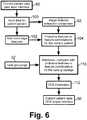
- An inference operation 110is performed by the CDS inference engine 54 in order to generate clinical decision support information 112 that is presented to the user via the current patient case CDS output interface 56.
- the CDS interface engine 54can be variously embodied.
- the distance or similarity metric or metrics 48are used to quantify the distance (or, analogously, to quantify similarity) of the current patient case respective to each case in each group of clinically related cases of the groupings 32.
- G matchmin g d c g , where d ( c,g ) represents the average value of the distance metric d for the current patient case denoted c from the cases that comprise a group denoted g , the operator min g ... denotes the minimum over all groups g of the groupings 32 , and G malrh represents the group at minimum distance (and hence, the group most similar to the current patient case c ).
- G matchmax g s c g .
- a trained classifierthat receives as inputs the probative features of the current patient case and outputs the most closely matching group.
- a trained classifiercan be trained, for example, using a training set of patient cases pre-annotated with the group identifications, as in the groupings 32.
- a k-nearest neighbour (k-NN) classifieris used, which provides an estimate of the posterior probability that a query case belongs to a patient case grouping. Based on the k most similar retrieved cases (shortest distances, in the case of a distance metric), this posterior probability is estimated by the number of cases of the patient case grouping in the k most similar cases divided by k. This is merely an illustrative example, and other classifiers can be used.
- breast canceris the most common cancer and the second most common cause of cancer death among women in the United States.
- CDS systems and methods based on content-based image retrieval (CBIR), as disclosed herein,mimic natural physician reasoning by retrieving similar cases that resemble previously reviewed and diagnosed patient cases. These methods rely on collected past experience and offer additional knowledge, such as automated identification of correlated probative features, to support physician decision-making. Therefore, the disclosed content-based CDS system for breast cancer diagnosis helps physicians to decide whether a queried case is likely to be malignant or benign, thus avoiding misinterpretation and preventing unnecessary biopsies.
- CBIRcontent-based image retrieval
- the probative features determination sub-system 12including a machine learning component 42, as disclosed herein, translates the physician's (or physicians') subjective sense of patient case similarity as reflected in the case groupings 32 into probative features 44 optionally including automatically computable metrics 46, 48.
- a CDS system based on CBIR, as disclosed herein, which is optimized on clinical similarity for breast cancer DCE-MRI studiesis expected to substantially improve physicians' diagnostic accuracy and is expected to reduce both unnecessary biopsies and delays in treatment.
- a content-based retrieval based on morphological and kinetic features extracted from DCE-MRI breast studiescan retrieve prior cases with the same diagnosis and similar imaging characteristics as the query case.
- the disclosed CDS systems and methodsenable grouping based on clinical similarity of breast cancer cases using the expertise of expert physicians. Probative image features and non-image features are identified based on cognitive analysis or other techniques for correlating features with the case groupings.
- the CBIR-based CDS systemis developed and optimized for the application of breast cancer diagnosis so as to substantially mirror the similarity judgments made by human physician experts. While using breast cancer diagnosis as an illustrative application, it will be appreciated that the underlying methodology can be generalized and adapted to other solid tumors, such as colon, lung, liver, brain cancer, and for diagnosis of other types of medical maladies, both in and outside of oncology.
Landscapes
- Health & Medical Sciences (AREA)
- Engineering & Computer Science (AREA)
- Biomedical Technology (AREA)
- Medical Informatics (AREA)
- Public Health (AREA)
- General Health & Medical Sciences (AREA)
- Primary Health Care (AREA)
- Epidemiology (AREA)
- Business, Economics & Management (AREA)
- General Business, Economics & Management (AREA)
- Pathology (AREA)
- Databases & Information Systems (AREA)
- Data Mining & Analysis (AREA)
- Nuclear Medicine, Radiotherapy & Molecular Imaging (AREA)
- Radiology & Medical Imaging (AREA)
- Measuring And Recording Apparatus For Diagnosis (AREA)
- Tourism & Hospitality (AREA)
- Accommodation For Nursing Or Treatment Tables (AREA)
- Medical Treatment And Welfare Office Work (AREA)
- User Interface Of Digital Computer (AREA)
- Marketing (AREA)
- Strategic Management (AREA)
- Physics & Mathematics (AREA)
- General Physics & Mathematics (AREA)
- Theoretical Computer Science (AREA)
- Human Resources & Organizations (AREA)
- Economics (AREA)
- Child & Adolescent Psychology (AREA)
Description
- The following relates to the medical arts, medical diagnostic arts, medical case management arts, expert system arts, and related arts.
- Clinical decision support (CDS) systems are expert systems constructed to provide automated assistance to physicians or other medical personnel in making medical decisions such as ailment diagnosis, treatment selection, implementation of aspects of a treatment regimen, and so forth. Some illustrative CDS systems are described, for example, in
Alsafadi, U.S. Publ. Appl. No. 2007/0175980 A1 . - In conventional or "manual" clinical diagnosis, case results from a physician's own experience guide the physician's decisions regarding new clinical situations. A case-based CDS system attempts to emulate this approach by facilitating automated access to a voluminous set of past cases that exceeds the historical experience possessed by any single physician. For example, a case-based CDS system can provide decision support for diagnosing an abnormality found in breast cancer studies of a patient by retrieving test results and other relevant information from past patient cases (with the patient data suitably anonymized to comply with patient privacy regulations or standards). Such case-based CDS systems emulate clinical decision-making thought processes that are generally accepted as proper in the medical arts. In effect, the CDS system operates as an information retrieval system which retrieves similar past medical cases, and may also retrieve or particularly identify relevant medical test results or other case information that is likely to be probative for a present diagnosis or other present medical decision.
- Known case-based CDS systems for automated decision-making employ various techniques to identify similar cases. In image retrieval, for example, pairwise comparison of image features is sometimes used to identify similar images. However, such approaches do not readily distinguish the "weights" or significance placed on the various image features in quantifying similarity or dissimilarity of the images. Moreover, if such pairwise comparisons are done manually, experimental or individual bias can be introduced due to the small and limited "sampling set" of two compared items.
- Various machine learning approaches have also been used in information retrieval systems in order to automatically group similar objects based on automated analysis of object features. Again, however, machine learning does not readily provide information as to the basis by which similarity or dissimilarity is assessed. The machine learned algorithm is a "black box" that may be suitable for applications such as image retrieval - but, a physician or other medical person is unlikely to be comfortable with making a medical diagnosis or other medical decision on an empirical basis without understanding the underlying decision-making rationale.
- Relevance feedback techniques are also known. In these techniques, human-performed or other authoritative analysis is applied to information retrieval results to assess the actual relevance of the retrieved information. These authoritative assessments are used to refine the information retrieval algorithm in the hope of improving subsequent retrieval operations. A difficulty with relevance feedback in the CDS context is that feedback over time is likely to come from different physicians, potentially resulting in differing or contradictory relevance feedback. Additionally, relevance feedback requires time to assess the retrieved results and provide the feedback, which a busy physician may be unwilling to do. Still further, relevance feedback only provides refinement for an existing information retrieval system and does not provide a basis for constructing a CDS systemab initio.
- The following provides new and improved apparatuses and methods which overcome the above-referenced problems and others.
- Document
US 2003/195883 A1 (MOJSILOVIC ALEKSANDRA [US] ET AL) 16 October 2003 (2003-10-16)) discloses a content-based image retrieval system applied to a clinical context, that allows grouping of images based on human perception, extraction of image features and derivation of relevant features for later retrievals. - Document
US 2008/298766 A1 (WEN FANG [CN] ET AL) 4 December 2008 (2008-12-04)) is a system for annotating photo albums, comprising clustering of related photos based on human perception, and drag&drop user interface and learning algorithms. - In accordance with one disclosed aspect, a clinical decision support (CDS) system comprises: a case grouping sub-system including a graphical user interface that is operative to simultaneously display data representing a plurality of patient cases and further configured to enable a user to group selected patient cases represented by the simultaneously displayed data into clinically related groups as selected by the user; a probative features determination sub-system that is operative to determine probative features that correlate with the clinically related groups; and a CDS user interface that is operative to receive current patient data relating to a current patient case and to output clinical decision support information based on values of the probative features determined from the received current patient data.
- In accordance with another disclosed aspect, a clinical decision support (CDS) method implemented by a CDS system is disclosed, the CDS method comprising: providing a graphical user interface by which a user groups patient cases into clinically related groups, the graphical user interface graphically representing patient cases by patient case icons comprising patient images or thumbnail images generated from patient images; determining probative features of the patient cases having values that correlate with the clinically related groups; and automatically providing clinical support decision information based on received current patient data relating to a current patient case based on values of the probative features determined from the received current patient data.
- In accordance with another disclosed aspect, a storage medium is disclosed, the storage medium storing instructions executable by a digital processor to perform the clinical decision support (CDS) method set forth in the immediately preceding paragraph.
- One advantage resides in providing patient case groupings determined holistically by a physician or other skilled medical person in order to establish similarity ground truth information for CDS operation.
- Another advantage resides in providing a user interface for manual grouping of similar patient cases in which the patient cases are represented by patient icons comprising patient images or thumbnail images generated from patient images.
- Another advantage resides in automatically determining image and optionally non-image features correlating with similarity ground truth information.
- Further advantages will be apparent to those of ordinary skill in the art upon reading and understanding the following detailed description.
FIGURE 1 diagrammatically shows a clinical decision support (CDS) system.FIGURES 2-4 diagrammatically shows display screenshots of the graphical user interface (GUI) of the case groupings sub-system of the CDS system ofFIGURE 1 .FIGURE 5 diagrammatically shows a suitable method performed by the probative features determination sub-system of the CDS system ofFIGURE 1 .FIGURE 6 diagrammatically shows a suitable method performed by the CDS user interface sub-system of the CDS system ofFIGURE 1 .- The present disclosure recognizes that the CDS system operation can be divided into two parts: (i) clustering of similar patient cases in order to identify a similarity "ground truth" (defined below at the end of the next paragraph); and (ii) the identification of probative features for clinical decision support. The present disclosure recognizes that part (i), the clustering of similar patient cases, is not readily automated in a manner acceptable to physicians. Automated machine learning techniques are generally too empirical, have too much potential to produce erroneous clusters, and do not provide a principled decision-making basis. Machine learning approaches also may fail to capture subjective or difficult-to-quantify factors routinely used by physicians in assessing cases and making complex medical diagnoses.
- Accordingly, the present application discloses a graphical user interface (GUI) that supports manual grouping of patient cases using a holistic visually-based GUI that concurrently displays more than two patient cases, and preferably a substantial number of patient cases, so as to avoid biases that can be introduced by limited pairwise comparisons. The output of the manual clustering is similarity ground truth information. The information is "ground truth" because the clusters are known or assumed to be correctly grouped because the grouping decisions were made by skilled physicians based on a substantial number of patient cases considered together.
- On the other hand, the present disclosure recognizes that part (ii), the identification of probative features, can advantageously be automated using machine learning. The automated identification of probative features can advantageously use as input the accurate similarity ground truth information. Automating part (ii) of the CDS system enhances efficiency and also provides information discovery because correlations between patient cases in the various groups are automatically identified. Such correlations are more likely to be unnoticed by a physician considering at most a few cases at a time. Advantageously, the machine-learned probative features can include non-image features such as patient age, patient gender, patient ethnicity, family medical history, genomic predispositions, and so forth.
- With reference to
FIGURE 1 , a clinical decision support (CDS) system includes a patientcase grouping sub-system 10 and a probativefeatures determination sub-system 12 that are operative to generate aCDS database 14 that is accessed by a CDSuser interface sub-system 16 to provide clinical support decision information. The patientcase grouping sub-system 10 operates on contents of adatabase 20 of patient cases. The patient cases are preferably anonymized by removing identifying information such as proper names, addresses, and so forth so as to comply with applicable privacy laws and standards. Thedatabase 20 of patient cases may be derived from contents of a hospital information network (not shown), and the data of the patient cases includes patient images acquired through one or more medical imaging modalities, such as one or more of: computed tomography (CT) imaging; magnetic resonance (MR) imaging; positron emission tomography (PET) imaging; single photon emission computed tomography (SPECT) imaging; fluoroscopy imaging, ultrasound imaging, x-ray imaging; and so forth. By way of example, patient images are optionally stored in a dedicated picture archiving and communications system (PACS)22 which stores medical patient images along with metadata such as information pertaining to medical imaging modality, resolution or other image acquisition parameters, acquisition time stamps, and so forth. - The patient cases are initially processed by a case grouping graphical user interface (GUI)30 of the
case grouping sub-system 10 that is operative to simultaneously display data relating to more than two different patient cases, for example represented as patient icons comprising patient images or thumbnail images generated from patient images. The term "thumbnail image" represents a reduced-resolution image generated by downsampling a higher-resolution image. By way of example, the thumbnail images are optionally of a standardized size and/or standardized aspect ratio (for example, all being 128×256 pixel images). The thumbnail images are optionally also "simplified" in other ways as compared with the source image, such as for example by converting a color image to a grayscale thumbnail image. By another exemplary option, the thumbnail images may be replaced by or augmented with non-image information, such as a summary block of text or a graphical representation of clinical data (e.g., graphs such as a line graph of blood pressure over time or the kinetic curves used in the analysis of MRI scans, or different types of plots such as a bar graph of a series of different measurements for each patient, such as age, height, weight, etc). - By concurrently displaying information for a substantial number of patient cases, the GUI30 avoids imposing pairwise comparisons between pairs of patient cases on the user which could disadvantageously lead to biased groupings. However, it is contemplated for the GUI30 to enable the user to select individual patient cases for more thorough review, for example by displaying non-image patient case information upon suitable selection via the GUI30 of a particular patient case. The GUI30 is further configured to enable a user to group the different patient cases represented by the simultaneously displayed data into clinically related groups as determined by the user. The user is preferably a physician or other skilled human medical diagnostician, or a plurality of physicians or other skilled human medical diagnosticians, who generate(s) clinically related groups. For example, the grouping of patient cases into clinically related groups can be performed by a single user (e.g., a single authoritative physician) or can be established as a consensus among a committee or other group of authoritative physicians or other authoritative medical personnel. The patient cases of a clinically related group are considered by the physician who generates the group to have a medical relationship such that a same or similar medical regimen is expected to be applicable to the patient cases in the group. For example, a clinically related group may comprise a group of patient cases in which all patients suffer from a same or similar type of cancer or other same or similar type of medical condition. Resulting
case groupings 32 are suitably stored in theCDS database 14. Optionally, thecase grouping sub-system 10 further includes a case groupings reportgenerator 34 that generates a human-readable report of the case groupings to provide a written record of the clinically related groups, or for optional review by other physicians or other skilled human medical diagnosticians, or for other purposes. - The clinically
related groups 32 are assumed to be correct, that is, are assumed to correctly group patient cases exhibiting a medically significant relationship entailing a same or similar medical regimen. This assumption is likely to be valid since the clinicallyrelated groups 32 were generated by a physician or other skilled human medical diagnostician, or by a plurality of physicians or other skilled human medical diagnosticians, based on a substantial number of patient cases presented by the GUI30 in a holistic fashion. On the basis of this assumption, the clinicallyrelated groups 32 are therefore understood to represent the similarity ground truth for the cases in thedatabase 20. Because the grouping was performed manually, thecase grouping sub-system 10 provides no express information as to the basis or rationale for the patient case groupings. Indeed, the physician or other skilled human medical diagnostician or plurality of physicians or other skilled human medical diagnosticians may have employed various objective and subjective considerations in generating the patient case groupings. - Although the bases used by the human diagnosticians in grouping together the various clinically
related groups 32 may not be readily available, it is reasonable to expect that the clinicallyrelated groups 32 have some objectively definable similarities or correlations, and that these objective similarities or correlations are latent information contained in the clinicallyrelated groups 32. - Accordingly, the probative
features determination sub-system 12 analyzes the clinicallyrelated groups 32 to identify probative features that correlate with the various groups. Toward this end, an image featuresextraction component 40 extracts quantitative image features that have reasonable likelihood of correlating with clinically significant aspects of the patient cases. Some illustrative examples of suitable quantitative image features include tumor size, tumor aspect ratio, tumor tissue density as reflected by image intensity in the tumor region, and so forth. Optionally, the image featuresextraction component 40 may be user-interactive - for example, the image featuresextraction component 40 may display a medical patient image and request that the user identify or delineate a tumor in the image using a mouse pointer or other user input mechanism. Additionally or alternatively, the image featuresextraction component 40 may employ automated tumor identification or other automated or semi-automated medical image analysis. In addition to image features, the probativefeatures determination sub-system 12 may consider non-image features such as patient age, patient gender, patient ethnicity, family medical history, genomic predispositions, and so forth, such information being provided in or derived from thepatient cases database 20. - An available feature may or may not be probative. That is, an available feature may correlate with one or more of the
patient case groups 32, in which case the feature is a probative feature, or the feature may have little or no correlation with any of thepatient case groups 32, in which case it is not probative. Features may also be probative in combination - for example, the features of tumor size and tumor aspect ratio, each standing alone, may have little correlation with any of thepatient case groups 32; whereas, the combination of tumor size and tumor aspect ratio together may correlate with one or more of the patient case groups32. - A
machine learning component 42 processes the available features to identify probative features or featurecombinations 44 that correlate with one or more of thepatient case groups 32, and these probative features or featurecombinations 44 are also stored in theCDS database 14. Themachine learning component 42 can employ any machine learning technique for identifying such correlations. In some illustrative examples set forth herein, themachine learning component 42 employs a genetic algorithm. Optionally, themachine learning component 42 also identifies the strength of correlation of a probative feature with thepatient case groups 32 and assignsfeature weights 46 that reflect the strength of correlation. Optionally, themachine learning component 42 also identifies combinations, or weighted combinations, of probative features that correlate with thepatient case groups 32, and stores these combinations or weighted combinations as distance orsimilarity metrics 48. Optionally, the identifiedprobative features information generator 34 or by another reporting tool. Optionally, the user can modify, delete, or otherwise adjust theprobative features information - The user who generates the
patient case groupings 32 with the assistance of thecase groupings sub-system 10, and who optionally reviews theprobative features information CDS database 14 is generally performed prior to the use of the CDS system for clinical decision support operations, although as disclosed herein occasional ongoing updates of theCDS database 14 are also contemplated. - Once the
CDS database 14 is populated, the contents of theCDS database 14 are used by the CDSuser interface sub-system 16 to generate clinical decision support information for presentation to a user. That is, clinical decision support operations are performed by the CDSuser interface sub-system 16 with reference to theCDS database 14. A human user, or plurality of human users, interact with the CDSuser interface sub-system 16 to request clinical decision support information for current patient cases. The user of the CDSuser interface sub-system 16 is typically a physician or other medical person or plurality of medical persons. However, the user of the CDSuser interface sub-system 16 is not necessarily a senior physician, specialist, or other highly skilled medical diagnostician. Rather, the user of the CDSuser interface sub-system 16 may be an ordinary physician of ordinary skill who utilizes the CDSuser interface sub-system 16 to obtain assistance in making clinical decisions. In general, the user of the CDSuser interface sub-system 16 may be a physician or other medical personnel of substantially any skill level. - The CDS
user interface sub-system 16 includes a current patient casedata input interface 50 via which a user inputs relevant information about a current patient case for which the user seeks clinical decision support. The provided current patient case information may include image data such as patient images, and optionally may also include non-image information such as patient age, patient gender, patient ethnicity, family medical history, genomic predispositions, and so forth. Patient images are processed by an image features extraction component52 (which may optionally be embodied in common with the image featuresextraction component 40 of the probative features determination sub-system12) to extract probative image features. The probative image features, together with any probative non-image features provided via the current patient casedata input interface 50, serve as inputs to a clinical decisionsupport inference engine 54 that considers correlations between values of the probative features of the current patient case and values of probative features of the cases of the variouspatient case groupings 32. By identifying common correlations, theinference engine 54 associates the current patient case with one of thepatient case groupings 32. A current patient case CDS output anduser validation interface 56 provides the user with clinical decision support information based on the results of theinference engine 54. For example, the clinical decision support information may include: identification of the patient case group most strongly associated with the current patient case; identification of the medical condition of that group with the proposal that the current patient may also have that medical condition; presentation of one or more similar cases extracted from the patient case group most strongly associated with the current patient case; presentation of a proposed medical regimen corresponding to a medical regimen applied in patient cases of the patient case group most strongly associated with the current patient case; or so forth. - Optionally, the current patient case CDS output and
user validation interface 56 also provides a user validation function in which the user accepts, rejects, or optionally modifies the presented clinical decision support information. In this case, the user validation information is optionally used by aCDS update sub-system 60 to assess and optionally update theCDS database 14. For example, in one approach the current patient case along with the medical diagnosis of the user (which may either agree with or disagree with the clinical decision support information provided by the CDS user interface sub-system16) is stored together with similar results for other "current" patient cases so as to provide an update or augmentation of the originalpatient cases database 20. Occasionally, the updated or augmented collection or database of patient cases is again processed by the CDS databasecontent generation components CDS database 14. In an alternative, computationally less intensive, approach, the current patient case is added to the patient case group of thecase groupings 32 if the user agrees that the current patient case does indeed belong with that patient case group. This can be done, for example, by providing the user with a GUI dialog box asking "Add current patient case to the «<»> group?" where "«<»>" is the identification of the patient case group indicated by the CDS system as matching the current patient case. - The CDS system of
FIGURE 1 can be implemented in various ways. In the illustrated embodiment, acomputer 70 includes adisplay 72 for displaying visual or graphical output of thecomponents 30, 56, for displaying dialog boxes, windows, or the like of theuser input component 50, and so forth. Thecomputer 70 also includes an illustratedkeyboard 74,mouse 76, and/or other user input device or devices for receiving user inputs, and still further includes a digital processor (not shown) and one or more storage media (not shown, but suitably embodied for example by a magnetic hard disk drive, an optical disk drive, a random access memory (RAM), a read-only memory (ROM), or so forth). The digital processor executes instructions of a computer program or computer code stored by the one or more storage media in order to implement theprocessing components CDS database 14 is suitably stored on one or more storage media of thecomputer 70 or on a remote storage medium accessed via a hospital digital network. In other contemplated embodiments, the processor embodying theprocessing components computer 70 provides the interfacinghardware - Having provided an overview of the illustrative CDS system of
FIGURE 1 which serves as an illustrative example herein, some additional or alternative aspects, and other disclosure are set forth. - In some illustrative embodiments set forth herein, the CDS system and corresponding CDS methods are described in the context of an illustrative breast cancer diagnostic application based on dynamic magnetic resonance imaging (MRI) and additional non-image clinical information. It is to be understood that this is merely an illustrative application and an illustrative imaging modality, and that the disclosed CDS systems and CDS methods are generally applicable to substantially any medical diagnostic application employing substantially any imaging modality that is probative for the medical application to which the CDS system or method is directed.
- Each patient case in the database can include multiple, different imaging studies from the same modality or different modalities. Furthermore, for each case, different views of these studies can be stored, or could be derived by image processing. Still further, a given patient case may in some cases be an amalgam or combination of images or other data acquired from two or more similar patients. The imaging studies stored for each patient case in the database can in general be acquired by one or more single imaging modalities, such as x-ray, ultrasound, MR, CT, and so forth, or by multiple imaging modalities for a single patient, such as x-ray mammography, ultrasound, MR breast studies. The imaging studies optionally include time series. For example, for a breast cancer case different dynamic contrast enhanced MR image series may be acquired. Thus, for each patient, the database can store pre-contrast (before the contrast agent administered to the patient), and multiple post-contrast studies, which are acquired at different time instants after the contrast agent has been administered. The database can also include derived sequences, such as multiple subtraction series, which are the subtraction of a pre-contrast study from different post-contrast series. The database optionally also includes derived image sequences representing the abnormalities and surrounding areas, e.g., volume of interests (VOI) for such variations. The
database 20 optionally further includes non-image based clinical information besides the imaging studies. Non-image data may include, for example, demographics information such as gender, age, ethnicity, personal medical history of the patient, family history, chief complains, genomic predispositions (e.g. in breast cancer BRCA1 and/or BRCA2 positive), and other risk factors. Thedatabase 20 suitably employs a hierarchical database model, a relational model by applying the SQL technique, or another suitable database configuration. - With reference to
FIGURE 2 , the interactive case grouping graphical user interface (GUI)30 displays data representing multiple patient cases on adisplay 80. Alefthand window 82 displays data representing ungrouped patient cases, while arighthand window 84 displays data representing grouped patient cases. Therighthand window 84 is empty inFIGURE 2 , indicating that no patient cases have yet been sorted into groups. It is to be understood that thedisplay 80 may include two or more display devices, such as two or more computer monitors, and the designation of "left" or "right" is arbitrary. For example, in some embodiments two computer monitors are provided - one monitor displays thewindow 82 showing ungrouped patient cases, while the other monitor displays thewindow 84 showing grouped patient cases. In the illustrative embodiments, the displayed representative data comprises a patient image or a thumbnail image generated from a patient image to represent each patient case. In other words, a patient image or corresponding thumbnail image serves as a patient icon for the graphical sorting process. Preferably, the displayed image represents the volume of interest (VOI) containing a clinical abnormality of interest. In the illustrative example ofFIGURE 2 , the representative images are VOIs which are derived as subtraction series (that is, 2nd post-contrast - pre-contrast T1- weighted MRI studies) and show breast lesions. - Optionally, non-image data is also displayable. For example,
FIGURE 2 shows a "pop-up window"86 showing non-image data such as "Age: 47" for a patient case responsive to the mouse or other pointer hovering over the representative patient icon. The pop-up window can be a temporary window that disappears once the mouse pointer is moved away, or can be a persistent window that remains open until it is closed. In some embodiments, hovering the mouse produces a temporary window with limited non-image information, while a positive user action such as clicking on the patient icon using themouse 76 produces a persistent window containing more information. In addition to showing non-image data, these approaches can additionally or alternatively be used to show image metadata such as acquisition timestamp, resolution, or so forth. - With reference to
FIGURE 3 , a positive user action such as clicking on the patient icon using themouse 76 may also optionally bring up more complete information. InFIGURE 3 , such an action causes more complete information about the selected patient case to be displayed so as to wholly occupy thelefthand window 82. Optionally, bothwindows FIGURE 3 , this mode displays for a breast cancer case a relevant dynamic contrast enhanced MR imaging study. It this example, thelefthand window 82 displays a bilateral view of the breast and an arrow pointing to the abnormality for easy identification. The arrow is suitably generated based on metadata identifying the abnormality stored in thePACS 22. Optionally, the GUI30 is configured to enable the user to selectively change views among different imaging studies of the clinical case. For breast MR imaging studies, for example, the user can optionally switch among pre-contrast, different post-contrast series, different acquisition series e.g.T2-weighted sequences, or derived sequences, such as subtraction series. For each series the user may optionally be able to change the window or level setting to have optimal view for the particular series and for different users. Kinetic curves can be displayed representing the uptake of the contrast agent in the abnormalities over time, as shown for example in the lower lefthand corner of thewindow 82 inFIGURE 3 . The upper left corner of this view also shows the neighbouring eight cases to be sorted and they are represented by the VOIs. The VOI in the middle is the case which whole breast view is shown on the right side. Under the bilateral view of the breast, the clinical information is displayed. Optionally, additional windows, parts of the monitor, or additional monitors can have the same functionality to show other clinical cases. For example, in some embodiments the twowindows - With reference to
FIGURE 4 , a screenshot is shown of the case grouping GUI30 being used to create clinically related groups as selected by the user. The user employs a drag-and-drop mechanism in which the patient case icons are dragged from thelefthand window 82 into a region of therighthand window 84 representing the group. To create a group, a patient case icon is dragged from thelefthand window 82 into an undesignated region of therighthand window 84 that defines a new group creation region. As the patient case icon is dropped into the new group creation region, a similarity group is created including that patient case. Optionally, the groups can be labeled or otherwise annotated by the user to indicate the basis of clinical relation of the patient cases in the group, or to provide other useful information. Optionally, the sub-window for a group may include scroll bars to accommodate more patient cases than can be displayed simultaneously, and/or can incorporate features such as zooming or panning through the use of keyboard, mouse, or other interaction devices. Optionally, a patient case can be moved from one group to another in accordance with a patient case reallocation decision by the user. Optionally, a patient case can be removed from any of the existing groups and replaced amongst the set of cases that have not yet been grouped, i.e. thelefthand window 82. The drag-and-drop operations can be implemented using themouse 76, or by using the keyboard74 (for example, tabbing through the various windows and sub-windows), or by other user interfacing operations. Still further, GUI manipulations such as lassoing and the like can be used to implement the grouping operations. - In the arrangement shown in
FIGURE 4 , each patient case is assigned exclusively to a single group of clinically related cases. In view of this, the patient case icon is removed from thelefthand window 82 when it is dragged-and-dropped into one of the groups in therighthand window 84, which is why the grid of patient case icons shown in thelefthand window 82 ofFIGURE 4 has numerous gaps. In an alternative embodiment, each patient case may optionally be assigned to two or more groups of clinically related cases. For example, a single patient case may be assigned to a group having as its clinical relationship a particular tumor characteristic, and may also be assigned to a group having as its clinical relationship image evidence of a certain level of metastasis. In this alternative embodiment, the patient case icon may be retained in thelefthand window 82 after being moved into a group on therighthand window 84, so as to continue to be available for inclusion in other groups of clinically related cases. - Once the user has completed allocation of patient cases into clinically related groups, for example as described with reference to
FIGURES 2-4 , the case groupings reportgenerator 34 is optionally invoked to generate a human-readable report describing the similarity groups. The report can, for example, be a free text report or a structured spreadsheet-based report. The description in the report of a clinically related group may include, for example: a group name; an identification of the cases contained in the group by subject ID (preferably anonymized), study ID, or so forth; a textual description of the group entered by the user; or so forth. A similarity group identifier is assigned to each case in the internal representation of the data. - In some embodiments, once a patient case icon has been dropped into a similarity group, the group identifier of the patient case is set to the identifier of that group. Thus, on report generation it is straightforward to determine the number of similarity groups. Once the total number of groups has been established the
report generator 34 loops through each group, finding the patient cases in that group and writing the relevant information into the report. Optionally, thereport generator 34 can also generate an intermediate report, without sorting all of the patient cases into similarity groups. - With reference to
FIGURE 5 , the similarity ground truth quantified by the clinicallyrelated groups 32 are processed to identify relevant (that is, probative) perceptual and clinical features distinguishing the groups from each other are obtained. In the illustrative embodiment, the probative features are obtained by an optimization of the selection of probative features respective to thecase groupings 32, suitably performed by applying image processing and machine learning techniques. This translates the similarity sense of the physician captured by thegroupings 32 defining the similarity ground truth into optimal computer-identified probative features. These probative features can then be used to represent patient cases in the CDS system. Optionally, an optimal distance or similarity metric is determined by machine learning techniques using the similarity ground truth as training data. As shown inFIGURE 5 , the images of thecase groupings 32 are processed by the image featuresextraction component 40 to identify image features. Optionally, non-image features are added90 to generate a set of available features92. A given available feature may or may not be probative, in that it may or may not be useful for discriminating amongst patient cases of thegroups 32. Then, using machine learning techniques feature selection is applied to find the probative feature set, and optionally to further find a distance or similarity metric employing the probative features. - In the illustrative embodiment of
FIGURE 5 , the machine learning employs a genetic algorithm coupled with k-mean clustering, and uses the established similarity clusters as ground truth. Genetic algorithms (GA) are useful for optimizing problems in high-dimensional spaces, and have been found to be useful in combinatorial problems such as feature selection. In GA-based feature selection, different feature subsets are encoded on a series of "chromosomes". A population of different chromosomes evolves through a process of mating (swapping features), reproduction, and mutation. Selection pressure is exercised such that the fittest chromosomes, as measured by a suitable fitness criterion, have the greatest chance to pass on their genetic information. The population thus evolves towards feature subsets that are optimal with respect to an objective function referred to as the fitness function or fitness criterion. - In some embodiments for finding the optimal feature subset and distance metric, genetic algorithms are coupled with k-nearest neighbor classification and using the established similarity clusters as ground truth. The genetic algorithm iteratively identifies candidate feature subsets, which are evaluated via a fitness function. Non-image-based clinical information are optionally added to the feature pool, for example using a scaling method of 1-of-C in order to scale with the image features.
- Chromosomes are constructed94 which represent available features. For example, each available feature can be represented by a binary gene of the chromosome, in which a binary value of "1" indicates the feature is a probative feature and a binary value of "0" indicates the feature is not probative. In a typical genetic algorithm, a substantial set (that is, "population") of chromosomes are generated with different genes randomly or pseudorandomly turned "on" (that is, having value "1" indicating the feature is probative) or "off" (that is, having value "0" indicating the feature is not probative). A
genetic algorithm 96 is then iteratively applied using as the selection algorithm correlation with thecase groupings 32 and incorporating random or pseudorandom gene mutation algorithms in order to optimize or "evolve" the chromosome population respective to correlation with thepatient case groupings 32. The "on" genes or combinations of "on" genes of the chromosomes of the evolved population then define the probative features or featurecombinations 44. - Optionally, the genes may have continuous values indicative of the strength of correlation of the corresponding features with the
case groupings 32, rather than having binary gene values. In these embodiments, the genetic algorithm evolves the weights of the genes of the chromosome population, so that the genes of the evolved population provide correlation weights for the probative features. In some such embodiments, the combination of weights that best correlates with thepatient case groupings 96, as represented by the combination of genes in the surviving evolved chromosomes, can also be used to define a distance or similarity metric. - For example, as the first step of one iteration of the
genetic algorithm 96, one patient case can be left out and distances are calculated between that patient case and all of the other cases using the features represented in the chromosome. The fitness function of thegenetic algorithm 96 can be determined as a function of these distances and the similarity groups to which the patient cases belong (e.g., by ranking the distances from the shortest to the longest, how many distances do not belong to the left out patient case's own similarity group). This can be done for each patient case in thegroups 32, and an accumulated fitness value is derived. Then, the chromosomes are modified or "mutated" in a random or pseudorandom fashion as per the principle of the chosengenetic algorithm 96. - In another embodiment, the genetic algorithm is constrained to always turn a certain group of features on or off together, such as may be dictated by a physician or other human medical diagnostician who knows that these features are related. In these embodiments, the construction of the chromosomes in
operation 94 can be performed in the following illustrative manner: a gene represents an available feature and genes which attempt to measure the same conceptual feature category are grouped together. In this manner thegenetic algorithm 96 is constrained such that the genetic algorithm never lets all of the genes representing the calculated measures for an aspect such as spiculation (for example) be discarded in total. That is, the genetic algorithm is constrained such that at least one spiculation feature or gene is always present in a chromosome since spiculation is known by human physicians to be a probative feature for breast cancer diagnoses. - In other embodiments, the type of distance metric (for example, a Euclidean distance, or a Mahalanobis or city block, or so forth) can be chosen by the
genetic algorithm 96 by including genes representing the different distance functions. - While the illustrative example of
FIGURE 5 employs a genetic algorithm for themachine learning component 42, this is merely an illustrative example. In general, themachine learning component 42 can employ substantially any machine learning method or combination of methods, including as some other illustrative examples: simulated annealing; exhaustive searches; floating searches; principle component analysis (PCA) or other feature reduction methods; or so forth. Moreover, it is contemplated to omit themachine learning component 42 and to configure the probativefeatures determination sub-system 12 to provide a graphical user interface that enables a physician or other human medical diagnostician, or a plurality of such physicians or other human medical diagnosticians, to select the probative features manually based on observations of the available features of the patient case groups32. For example, the list of probative perceptual and clinical features can optionally be obtained manually from the physician using cognitive methods. As a specific example, in a breast cancer application based on dynamic contrast enhanced MR imaging, the morphological features of the abnormalities and the surrounding areas, such as shape, margin, texture, kinetic curves, or so forth, may be calculated in various ways by image processing techniques, and examined for probativeness by the physician. The physician knows, for example, that spiculation is a probative feature for breast cancer diagnoses, and so the physician is likely to consider different spiculation measures as candidate probative features. By examining values of the different spiculation measures amongst the patient cases of thepatient case groups 32, the physician can manually select those spiculation measures that most strongly correlate with thegroupings 32 as probative features. Manual cognitive analysis techniques can also be advantageously combined with machine learning approaches. For example, cognitive analysis can be used to generate a set of "candidate" probative features, followed by PCA or another features reduction method to reduce the number of probative features. - With reference to
FIGURE 6 , an illustrative operation of the CDSuser interface sub-system 16 is described. The current patient casedata input interface 50 is accessed by a user to input data for acurrent patient 100. The input currentpatient data 100 generally includes one or more patient images, such as images of the patient acquired by one or more of: CT imaging, MR imaging, PET imaging, SPECT imaging, fluoroscopy imaging, ultrasound imaging, and x-ray imaging. The image featuresextraction component 52 processes these current patient images to extract probative image features, and optionally probative non-image features102 are combined with the probative image features to define a set of probative features or feature combinations for the currentpatient case 104. As noted earlier, the image featuresextraction component 52 may optionally be embodied by the same component embodying the image featuresextraction component 40 of the probativefeatures determination sub-system 12. - An
inference operation 110 is performed by theCDS inference engine 54 in order to generate clinicaldecision support information 112 that is presented to the user via the current patient caseCDS output interface 56. TheCDS interface engine 54 can be variously embodied. In some embodiments, the distance or similarity metric ormetrics 48 are used to quantify the distance (or, analogously, to quantify similarity) of the current patient case respective to each case in each group of clinically related cases of thegroupings 32. For a distance metric, the inference employs the following relation:

groupings 32, andGmalrh represents the group at minimum distance (and hence, the group most similar to the current patient casec). For a similarity metrics, the analogous expression is:
groupings 32. In some embodiments, a k-nearest neighbour (k-NN) classifier is used, which provides an estimate of the posterior probability that a query case belongs to a patient case grouping. Based on the k most similar retrieved cases (shortest distances, in the case of a distance metric), this posterior probability is estimated by the number of cases of the patient case grouping in the k most similar cases divided by k. This is merely an illustrative example, and other classifiers can be used. - The following describes further aspects of a proposed embodiment directed to diagnosing breast cancer. Presently, breast cancer is the most common cancer and the second most common cause of cancer death among women in the United States. CDS systems and methods based on content-based image retrieval (CBIR), as disclosed herein, mimic natural physician reasoning by retrieving similar cases that resemble previously reviewed and diagnosed patient cases. These methods rely on collected past experience and offer additional knowledge, such as automated identification of correlated probative features, to support physician decision-making. Therefore, the disclosed content-based CDS system for breast cancer diagnosis helps physicians to decide whether a queried case is likely to be malignant or benign, thus avoiding misinterpretation and preventing unnecessary biopsies. While dynamic contrast-enhanced MRI (DCE-MRI) has emerged as a main diagnostic tool for breast lesion characterization due to its superior sensitivity, it often leads to a high incidence of negative biopsies. The probative features
determination sub-system 12 including amachine learning component 42, as disclosed herein, translates the physician's (or physicians') subjective sense of patient case similarity as reflected in thecase groupings 32 intoprobative features 44 optionally including automaticallycomputable metrics - A CDS system based on CBIR, as disclosed herein, which is optimized on clinical similarity for breast cancer DCE-MRI studies is expected to substantially improve physicians' diagnostic accuracy and is expected to reduce both unnecessary biopsies and delays in treatment. A content-based retrieval based on morphological and kinetic features extracted from DCE-MRI breast studies can retrieve prior cases with the same diagnosis and similar imaging characteristics as the query case. The disclosed CDS systems and methods enable grouping based on clinical similarity of breast cancer cases using the expertise of expert physicians. Probative image features and non-image features are identified based on cognitive analysis or other techniques for correlating features with the case groupings. By integrating advanced computer vision, image processing and machine learning techniques the CBIR-based CDS system is developed and optimized for the application of breast cancer diagnosis so as to substantially mirror the similarity judgments made by human physician experts. While using breast cancer diagnosis as an illustrative application, it will be appreciated that the underlying methodology can be generalized and adapted to other solid tumors, such as colon, lung, liver, brain cancer, and for diagnosis of other types of medical maladies, both in and outside of oncology.
- This application has described one or more preferred embodiments. Modifications and alterations may occur to others upon reading and understanding the preceding detailed description. It is intended that the application be construed as including all such modifications and alterations insofar as they come within the scope of the appended claims or the equivalents thereof.


Claims (14)
- A clinical decision support (CDS) system comprising:- a case grouping sub-system (10) including a graphical user interface (30) that is operative to simultaneously display data representing a plurality of patient cases and further configured to enable a user to manually group selected patient cases represented by the simultaneously displayed data into clinically related groups (32) as selected by the user;- a probative features determination sub-system (12) that is operative to determine probative features (44) that correlate with the clinically related groups (32); and- a CDS user interface (16) that is operative to receive current patient data relating to a current patient case and to output clinical decision support information based on the correlations between values of the probative features determined from the received current patient data and values of probative features determined from the clinically related groups (32),wherein the graphical user interface (30) is operative to provide drag-and-drop case grouping in which a user drags displayed data representing a patient case from a source visual display region (82) to a region (84) representing a clinically related group, and
wherein the displayed data representing a patient case comprises a patient image. - The CDS system as set forth in claim 1, wherein the case grouping sub-system (10) including a graphical user interface (30) is operative to provide a drag-and-drop grouping in which a user drags displayed data representing a patient case from a source visual display region (82) to a new group creation region (84) to create a clinically related group.
- The CDS system as set forth in any one of claims 1-2, wherein the displayed data representing a patient case comprises a thumbnail image generated from a patient image.
- The CDS system as set forth in claim 1, wherein the case grouping sub-system (10) including a graphical user interface (30) is operative to concurrently display patient case icons comprising patient images or thumbnail images generated from patient images and to enable a user to graphically group selected patient case icons into clinically related groups as selected by the user.
- The CDS system as set forth in claim 1, 3 or4, wherein the patient images are one or more of: computed tomography (CT) images, magnetic resonance (MR) images, positron emission tomography (PET) images, single photon emission computed tomography (SPECT) images, fluoroscopy images, ultrasound images, and x-ray images.
- The CDS system as set forth in any one of claims 1-5, wherein the probative features determination sub-system (12) includes a machine learning component (42) that is operative to automatically determine probative features (44) having values for different patient cases that correlate with the clinically related groups (32).
- The CDS system as set forth in claim 6, wherein the probative features determination sub-system (12) including a machine learning component (42) is further operative to automatically determine a distance or similarity function (48) combining the probative features (44).
- The CDS system as set forth in any one of claims 1-7, wherein the probative features determination sub-system (12) further comprises:- an image features extraction component (40) operative to extract image features from a patient image, the machine learning component (42) operating on at least the image features.
- The CDS system as set forth in any one of claims 1-8, wherein the CDS user interface (16) comprises:- an inference engine (54) operative to generate the clinical decision support information based on the correlations between values of the probative features determined from the received current patient data and values of probative features determined from the clinically related groups (32).
- A clinical decision support (CDS) method implemented by a CDS system, the CDS method comprising:- providing a graphical user interface (30) by which a user manually groups patient cases into clinically related groups (32), the graphical user interface graphically representing patient cases by patient case icons comprising patient images or thumbnail images generated from patient images;- determining probative features (44) of the patient cases having values that correlate with the clinically related groups (32);- providing a CDS user interface (16) for receiving current patient data relating to a current patient case; and- automatically providing clinical support decision information based on the correlations between values of the probative features determined from the received current patient data and values of probative features determined from the clinically related groups (32),wherein the graphical user interface (30) is operative to provide drag-and-drop case grouping in which a user drags the patient case from a source visual display region (82) to a region (84) representing a clinically related group.
- The CDS method as set forth in claim 10, wherein the graphical user interface (30) provides drag-and-drop manipulation of the patient case icons by which a user groups patient cases into clinically related groups (32).
- The CDS method as set forth in any one of claims 10-11, wherein the determining comprises:- automatically determining probative features (42) of the patient cases having values that correlate with the clinically related groups (32) using a machine learning component (42).
- The CDS method as set forth in claim 12, wherein the automatic determining further comprises:- extracting image features from patient images, the image features being processed by the machine learning component (42).
- The CDS method as set forth in any one of claims 12-13, wherein the machine learning component (42) further processes at least some non-image features.
Priority Applications (1)
| Application Number | Priority Date | Filing Date | Title |
|---|---|---|---|
| PL10719078TPL2419849T3 (en) | 2009-04-15 | 2010-03-09 | Clinical decision support systems and methods |
Applications Claiming Priority (2)
| Application Number | Priority Date | Filing Date | Title |
|---|---|---|---|
| US16947309P | 2009-04-15 | 2009-04-15 | |
| PCT/IB2010/051013WO2010119356A2 (en) | 2009-04-15 | 2010-03-09 | Clinical decision support systems and methods |
Publications (2)
| Publication Number | Publication Date |
|---|---|
| EP2419849A2 EP2419849A2 (en) | 2012-02-22 |
| EP2419849B1true EP2419849B1 (en) | 2017-11-29 |
Family
ID=42229296
Family Applications (1)
| Application Number | Title | Priority Date | Filing Date |
|---|---|---|---|
| EP10719078.7AActiveEP2419849B1 (en) | 2009-04-15 | 2010-03-09 | Clinical decision support systems and methods |
Country Status (8)
| Country | Link |
|---|---|
| US (1) | US10504197B2 (en) |
| EP (1) | EP2419849B1 (en) |
| JP (1) | JP5506912B2 (en) |
| CN (1) | CN102395975B (en) |
| BR (1) | BRPI1006388A2 (en) |
| PL (1) | PL2419849T3 (en) |
| RU (1) | RU2543563C2 (en) |
| WO (1) | WO2010119356A2 (en) |
Families Citing this family (73)
| Publication number | Priority date | Publication date | Assignee | Title |
|---|---|---|---|---|
| EP2419849B1 (en)* | 2009-04-15 | 2017-11-29 | Koninklijke Philips N.V. | Clinical decision support systems and methods |
| US20120116804A1 (en)* | 2010-11-04 | 2012-05-10 | International Business Machines Corporation | Visualization of social medical data |
| US20120159395A1 (en) | 2010-12-20 | 2012-06-21 | Microsoft Corporation | Application-launching interface for multiple modes |
| EP3242270B1 (en)* | 2010-12-20 | 2021-03-03 | Koninklijke Philips N.V. | System and method for automatic generation of initial radiation treatment plans |
| US8689123B2 (en) | 2010-12-23 | 2014-04-01 | Microsoft Corporation | Application reporting in an application-selectable user interface |
| US8612874B2 (en) | 2010-12-23 | 2013-12-17 | Microsoft Corporation | Presenting an application change through a tile |
| US9423951B2 (en) | 2010-12-31 | 2016-08-23 | Microsoft Technology Licensing, Llc | Content-based snap point |
| US9383917B2 (en) | 2011-03-28 | 2016-07-05 | Microsoft Technology Licensing, Llc | Predictive tiling |
| US20120272171A1 (en)* | 2011-04-21 | 2012-10-25 | Panasonic Corporation | Apparatus, Method and Computer-Implemented Program for Editable Categorization |
| US9158445B2 (en) | 2011-05-27 | 2015-10-13 | Microsoft Technology Licensing, Llc | Managing an immersive interface in a multi-application immersive environment |
| US8893033B2 (en) | 2011-05-27 | 2014-11-18 | Microsoft Corporation | Application notifications |
| US20120304132A1 (en) | 2011-05-27 | 2012-11-29 | Chaitanya Dev Sareen | Switching back to a previously-interacted-with application |
| US9658766B2 (en) | 2011-05-27 | 2017-05-23 | Microsoft Technology Licensing, Llc | Edge gesture |
| US9104440B2 (en) | 2011-05-27 | 2015-08-11 | Microsoft Technology Licensing, Llc | Multi-application environment |
| US9104307B2 (en) | 2011-05-27 | 2015-08-11 | Microsoft Technology Licensing, Llc | Multi-application environment |
| US20130057587A1 (en) | 2011-09-01 | 2013-03-07 | Microsoft Corporation | Arranging tiles |
| US20130067412A1 (en)* | 2011-09-09 | 2013-03-14 | Microsoft Corporation | Grouping selectable tiles |
| US9557909B2 (en) | 2011-09-09 | 2017-01-31 | Microsoft Technology Licensing, Llc | Semantic zoom linguistic helpers |
| US8922575B2 (en) | 2011-09-09 | 2014-12-30 | Microsoft Corporation | Tile cache |
| US10353566B2 (en) | 2011-09-09 | 2019-07-16 | Microsoft Technology Licensing, Llc | Semantic zoom animations |
| US9244802B2 (en) | 2011-09-10 | 2016-01-26 | Microsoft Technology Licensing, Llc | Resource user interface |
| US9146670B2 (en) | 2011-09-10 | 2015-09-29 | Microsoft Technology Licensing, Llc | Progressively indicating new content in an application-selectable user interface |
| US8553965B2 (en)* | 2012-02-14 | 2013-10-08 | TerraRecon, Inc. | Cloud-based medical image processing system with anonymous data upload and download |
| US8682049B2 (en) | 2012-02-14 | 2014-03-25 | Terarecon, Inc. | Cloud-based medical image processing system with access control |
| US20130226612A1 (en)* | 2012-02-26 | 2013-08-29 | International Business Machines Corporation | Framework for evidence based case structuring |
| US11170013B2 (en)* | 2012-04-02 | 2021-11-09 | Koninklijke Philips N.V. | Pathway visualization for clinical decision support |
| US9274678B2 (en)* | 2012-09-13 | 2016-03-01 | Google Inc. | Identifying a thumbnail image to represent a video |
| US9053219B2 (en)* | 2012-09-14 | 2015-06-09 | General Electric Company | Patient monitoring system and method |
| JP6552966B2 (en)* | 2012-12-28 | 2019-07-31 | ボルケーノ コーポレイション | Device, system and method for data processing in an invasive context, multimodality medical system |
| US10409951B2 (en) | 2012-12-28 | 2019-09-10 | Volcano Corporation | Multi-modality case management system and method |
| US11120896B2 (en) | 2012-12-28 | 2021-09-14 | Philips Image Guided Therapy Corporation | Multi-modality anonymizing system and method |
| US10453561B2 (en) | 2012-12-28 | 2019-10-22 | Volcano Corporation | Multi-modality case explorer system and method |
| JP5668090B2 (en)* | 2013-01-09 | 2015-02-12 | キヤノン株式会社 | Medical diagnosis support apparatus and medical diagnosis support method |
| US9949696B2 (en)* | 2013-03-14 | 2018-04-24 | Tensys Medical, Inc. | Apparatus and methods for computing cardiac output of a living subject via applanation tonometry |
| US10354281B2 (en)* | 2013-10-31 | 2019-07-16 | International Business Machines Corporation | Communicating with a customer traveling on a route to a location |
| US10978208B2 (en)* | 2013-12-05 | 2021-04-13 | International Business Machines Corporation | Patient risk stratification by combining knowledge-driven and data-driven insights |
| US9373075B2 (en)* | 2013-12-12 | 2016-06-21 | International Business Machines Corporation | Applying a genetic algorithm to compositional semantics sentiment analysis to improve performance and accelerate domain adaptation |
| US9152761B2 (en) | 2014-01-10 | 2015-10-06 | Heartflow, Inc. | Systems and methods for identifying medical image acquisition parameters |
| CN106233322A (en)* | 2014-03-03 | 2016-12-14 | 赛曼提克姆德公司 | Patient's searching system based on individualized content |
| CN105359094A (en) | 2014-04-04 | 2016-02-24 | 微软技术许可有限责任公司 | Extensible Application Representation |
| KR102107275B1 (en) | 2014-04-10 | 2020-05-06 | 마이크로소프트 테크놀로지 라이센싱, 엘엘씨 | Collapsible shell cover for computing device |
| KR20160143784A (en) | 2014-04-10 | 2016-12-14 | 마이크로소프트 테크놀로지 라이센싱, 엘엘씨 | Slider cover for computing devices |
| EP3178060A4 (en)* | 2014-08-07 | 2018-03-28 | Curelator Inc. | Chronic disease discovery and management system |
| CN106796621B (en)* | 2014-09-10 | 2021-08-24 | 皇家飞利浦有限公司 | Image report annotation recognition |
| CN107004043B (en)* | 2014-11-07 | 2022-07-29 | 皇家飞利浦有限公司 | System and method for optimized detection and labeling of anatomical structures of interest |
| WO2016098066A1 (en)* | 2014-12-19 | 2016-06-23 | Koninklijke Philips N.V. | Automated derivation of quality assurance rules |
| US9626267B2 (en) | 2015-01-30 | 2017-04-18 | International Business Machines Corporation | Test generation using expected mode of the target hardware device |
| CN107530452A (en) | 2015-02-02 | 2018-01-02 | 诺瓦达克技术公司 | Methods and systems for characterizing tissue of a subject |
| EP3262605A1 (en) | 2015-02-26 | 2018-01-03 | Brainlab AG | Adaptation of image data sets to an updated atlas-based reference system |
| US20160306936A1 (en)* | 2015-04-15 | 2016-10-20 | Canon Kabushiki Kaisha | Diagnosis support system, information processing method, and program |
| RU2613029C2 (en)* | 2015-05-05 | 2017-03-14 | Ольга Анатольевна Клочихина | Automated system of forming extended register of stroke |
| RU2598578C1 (en)* | 2015-05-05 | 2016-09-27 | Ольга Анатольевна Клочихина | Method for prevention incidence of stroke |
| RU2622498C1 (en)* | 2016-01-26 | 2017-06-15 | Ольга Викторовна Гончарова | Method for medical care quality increase related to electronic information system |
| US11854694B2 (en) | 2016-03-16 | 2023-12-26 | Koninklijke Philips N.V. | Relevance feedback to improve the performance of clustering model that clusters patients with similar profiles together |
| WO2018018160A1 (en) | 2016-07-29 | 2018-02-01 | Novadaq Technologies ULC | Methods and systems for characterizing tissue of a subject utilizing machine learning |
| US10025902B2 (en)* | 2016-08-12 | 2018-07-17 | Verily Life Sciences Llc | Enhanced pathology diagnosis |
| US11195313B2 (en)* | 2016-10-14 | 2021-12-07 | International Business Machines Corporation | Cross-modality neural network transform for semi-automatic medical image annotation |
| EP3622530A1 (en)* | 2017-05-10 | 2020-03-18 | Koninklijke Philips N.V. | A cohort explorer for visualizing comprehensive sample relationships through multi-modal feature variations |
| EP3460807A1 (en) | 2017-09-20 | 2019-03-27 | Koninklijke Philips N.V. | Subject clustering method and apparatus |
| US20190147620A1 (en)* | 2017-11-14 | 2019-05-16 | International Business Machines Corporation | Determining optimal conditions to photograph a point of interest |
| US11393587B2 (en)* | 2017-12-04 | 2022-07-19 | International Business Machines Corporation | Systems and user interfaces for enhancement of data utilized in machine-learning based medical image review |
| US10922944B2 (en) | 2018-06-28 | 2021-02-16 | Hill-Rom Services, Inc. | Methods and systems for early detection of caregiver concern about a care recipient, possible caregiver impairment, or both |
| US11302423B2 (en)* | 2019-01-23 | 2022-04-12 | International Business Machines Corporation | Predicting patients who can benefit from a clinical trial |
| JP7122279B2 (en)* | 2019-03-15 | 2022-08-19 | 株式会社日立製作所 | Medical institution selection server and medical institution selection method |
| CN110517745B (en)* | 2019-08-15 | 2023-06-27 | 中山大学肿瘤防治中心 | Medical examination result display method and device, electronic equipment and storage medium |
| CN110584605B (en)* | 2019-09-10 | 2023-01-31 | 江苏恒盛信息技术有限公司 | Similarity-matched diagnosis and monitoring comprehensive medical system and matching method thereof |
| CN111091907A (en)* | 2019-11-15 | 2020-05-01 | 合肥工业大学 | Health care knowledge retrieval method and system based on similar case database |
| RU197528U1 (en)* | 2019-12-26 | 2020-05-12 | федеральное государственное автономное образовательное учреждение высшего образования "Санкт-Петербургский политехнический университет Петра Великого" (ФГАОУ ВО "СПбПУ") | Compression unit for fixing the mammary gland with a non-invasive method for its research and / or treatment |
| US20220076831A1 (en)* | 2020-09-09 | 2022-03-10 | Koninklijke Philips N.V. | System and method for treatment optimization using a similarity-based policy function |
| US12014807B2 (en)* | 2021-12-10 | 2024-06-18 | Merative Us L.P. | Automated report generation using artificial intelligence algorithms |
| US12393859B2 (en)* | 2022-06-13 | 2025-08-19 | Bank Of America Corporation | Non-linear data dependency detection in machine learning using hybrid quantum computing |
| WO2025166428A1 (en)* | 2024-02-05 | 2025-08-14 | Гасан Сулейман оглу СУЛЕЙМАНОВ | Modular clinical decision support system for diagnosis and treatment |
| EP4604057A1 (en) | 2024-02-19 | 2025-08-20 | Future Processing S.A. | Method for automated analysis of brain tumors in dynamic contrast-enhanced magnetic resonance images |
Family Cites Families (21)
| Publication number | Priority date | Publication date | Assignee | Title |
|---|---|---|---|---|
| AU2001291175A1 (en) | 2000-09-21 | 2002-04-02 | Md Online Inc. | Medical image processing systems |
| US7043474B2 (en)* | 2002-04-15 | 2006-05-09 | International Business Machines Corporation | System and method for measuring image similarity based on semantic meaning |
| CN1894697A (en) | 2003-12-16 | 2007-01-10 | 皇家飞利浦电子股份有限公司 | Clinical decision support system for guideline selection and knowledge/location indication with the guideline |
| US20080192995A1 (en) | 2004-01-26 | 2008-08-14 | Koninklijke Philips Electronic, N.V. | Example-Based Diagnosis Decision Support |
| US20050261941A1 (en) | 2004-05-21 | 2005-11-24 | Alexander Scarlat | Method and system for providing medical decision support |
| RU2299470C2 (en)* | 2004-09-09 | 2007-05-20 | Институт иммунологии и физиологии Уральского отделения Российской Академии наук (ИИФ УрО РАН) | Method for building unified information space for practical doctor |
| RU2285950C2 (en)* | 2004-11-05 | 2006-10-20 | Виктор Валентинович Омельченко | Visual presentation and dynamic analysis method for studying living organism health state |
| JP2006146623A (en)* | 2004-11-19 | 2006-06-08 | Takahiko Tomoyose | Image data editing system and computer program |
| US20060231108A1 (en) | 2005-04-18 | 2006-10-19 | General Electric Company | Method and apparatus for managing multi-patient contexts on a picture archiving and communication system |
| CN101346722A (en)* | 2005-10-31 | 2009-01-14 | 皇家飞利浦电子股份有限公司 | Clinical workflow management and decision system and method |
| JP4799251B2 (en)* | 2006-04-05 | 2011-10-26 | 富士フイルム株式会社 | Similar case search device, similar case search method and program thereof |
| TW200817956A (en) | 2006-06-16 | 2008-04-16 | Koninkl Philips Electronics Nv | Clinician-driven example-based computer-aided diagnosis |
| JP4493637B2 (en) | 2006-09-29 | 2010-06-30 | オリンパス株式会社 | Diagnosis support apparatus and diagnosis support method |
| JP4979334B2 (en)* | 2006-10-18 | 2012-07-18 | 富士フイルム株式会社 | Medical image interpretation support system and program |
| JP5125128B2 (en)* | 2007-02-01 | 2013-01-23 | コニカミノルタエムジー株式会社 | Medical image management system and data management method |
| US8189880B2 (en)* | 2007-05-29 | 2012-05-29 | Microsoft Corporation | Interactive photo annotation based on face clustering |
| JP2008300652A (en)* | 2007-05-31 | 2008-12-11 | Toshiba Corp | Manufacturing method of semiconductor device |
| WO2009143040A1 (en)* | 2008-05-19 | 2009-11-26 | Disetronic Medical Systems Ag | Computer research tool for the organization, visualization and analysis of metabolic-related clinical data and method thereof |
| US8607148B2 (en)* | 2008-08-26 | 2013-12-10 | General Electric Company | Method and system for performing drag and drop operation |
| US20110166879A1 (en)* | 2008-09-26 | 2011-07-07 | Koninklijke Philips Electronics N.V. | System and method for fusing clinical and image features for computer-aided diagnosis |
| EP2419849B1 (en)* | 2009-04-15 | 2017-11-29 | Koninklijke Philips N.V. | Clinical decision support systems and methods |
- 2010
- 2010-03-09EPEP10719078.7Apatent/EP2419849B1/enactiveActive
- 2010-03-09BRBRPI1006388Apatent/BRPI1006388A2/ennot_activeIP Right Cessation
- 2010-03-09CNCN201080016586.0Apatent/CN102395975B/ennot_activeExpired - Fee Related
- 2010-03-09WOPCT/IB2010/051013patent/WO2010119356A2/enactiveApplication Filing
- 2010-03-09JPJP2012505254Apatent/JP5506912B2/ennot_activeExpired - Fee Related
- 2010-03-09PLPL10719078Tpatent/PL2419849T3/enunknown
- 2010-03-09USUS13/264,657patent/US10504197B2/enactiveActive
- 2010-03-09RURU2011146142/08Apatent/RU2543563C2/enactive
Also Published As
| Publication number | Publication date |
|---|---|
| BRPI1006388A2 (en) | 2020-02-04 |
| CN102395975B (en) | 2016-02-10 |
| WO2010119356A3 (en) | 2010-12-02 |
| EP2419849A2 (en) | 2012-02-22 |
| RU2011146142A (en) | 2013-05-20 |
| WO2010119356A2 (en) | 2010-10-21 |
| RU2543563C2 (en) | 2015-03-10 |
| JP2012523877A (en) | 2012-10-11 |
| US10504197B2 (en) | 2019-12-10 |
| CN102395975A (en) | 2012-03-28 |
| JP5506912B2 (en) | 2014-05-28 |
| PL2419849T3 (en) | 2018-05-30 |
| US20120041779A1 (en) | 2012-02-16 |
Similar Documents
| Publication | Publication Date | Title |
|---|---|---|
| EP2419849B1 (en) | Clinical decision support systems and methods | |
| JP4799251B2 (en) | Similar case search device, similar case search method and program thereof | |
| RU2533500C2 (en) | System and method for combining clinical signs and image signs for computer-aided diagnostics | |
| JP5952835B2 (en) | Imaging protocol updates and / or recommenders | |
| US20170193660A1 (en) | Identifying a Successful Therapy for a Cancer Patient Using Image Analysis of Tissue from Similar Patients | |
| JP2023503610A (en) | Co-registration of medical scan images and method of use therewith | |
| JP7021215B2 (en) | CAD System Personalization Methods and Means for Providing Confidence Level Indicators for CAD System Recommendations | |
| US20220037019A1 (en) | Medical scan artifact detection system and methods for use therewith | |
| Taylor | Computer aids for decision-making in diagnostic radiology—a literature review | |
| JP5431924B2 (en) | Clinician-driven, example-based computer-aided diagnosis | |
| WO2006096364A2 (en) | Performance adjustments in medical decision support systems | |
| JP2007280229A (en) | Similar case search device, similar case search method and program thereof | |
| EP3955260A1 (en) | Clinical decision support | |
| US20200294655A1 (en) | System and method to automatically prepare an attention list for improving radiology workflow | |
| Velarde et al. | Robustness of deep networks for mammography: Replication across public datasets | |
| JP7157232B2 (en) | Finding Similar Images for Radiology | |
| CN1820274A (en) | Using machine learning to adapt the CAD process with knowledge gathered during routine use of the CAD system to provide CAD (Computer Aided Decision) support for medical imaging | |
| US20210407655A1 (en) | Medical data processing apparatus, medical data processing method, and non-transitory computer medium storing computer program | |
| Donteu et al. | Sparse activations for interpretable disease grading | |
| Donteu Djoumessi et al. | Sparse Activations for Interpretable Disease Grading | |
| IL291370B1 (en) | A medical data storage and retrieval system and method thereof | |
| BURTSEVA et al. | IMAGES AND RULES-BASED DECISION SUPPORT SYSTEM IN ULTRASOUND EXAMINATION OF ABDOMINAL ZONE | |
| CN115605890A (en) | Context-based performance benchmarking | |
| Alto | Indexed atlas for computer-aided diagnosis of breast cancer | |
| Lo | Computer-Aided Mammography Using Automated Feature Extraction for the Detection and Diagnosis of Breast Cancer |
Legal Events
| Date | Code | Title | Description |
|---|---|---|---|
| PUAI | Public reference made under article 153(3) epc to a published international application that has entered the european phase | Free format text:ORIGINAL CODE: 0009012 | |
| 17P | Request for examination filed | Effective date:20111115 | |
| AK | Designated contracting states | Kind code of ref document:A2 Designated state(s):AT BE BG CH CY CZ DE DK EE ES FI FR GB GR HR HU IE IS IT LI LT LU LV MC MK MT NL NO PL PT RO SE SI SK SM TR | |
| DAX | Request for extension of the european patent (deleted) | ||
| RAP1 | Party data changed (applicant data changed or rights of an application transferred) | Owner name:PHILIPS INTELLECTUAL PROPERTY & STANDARDS GMBH Owner name:KONINKLIJKE PHILIPS N.V. | |
| 17Q | First examination report despatched | Effective date:20140106 | |
| GRAP | Despatch of communication of intention to grant a patent | Free format text:ORIGINAL CODE: EPIDOSNIGR1 | |
| INTG | Intention to grant announced | Effective date:20170623 | |
| GRAS | Grant fee paid | Free format text:ORIGINAL CODE: EPIDOSNIGR3 | |
| GRAA | (expected) grant | Free format text:ORIGINAL CODE: 0009210 | |
| AK | Designated contracting states | Kind code of ref document:B1 Designated state(s):AT BE BG CH CY CZ DE DK EE ES FI FR GB GR HR HU IE IS IT LI LT LU LV MC MK MT NL NO PL PT RO SE SI SK SM TR | |
| REG | Reference to a national code | Ref country code:CH Ref legal event code:EP | |
| REG | Reference to a national code | Ref country code:AT Ref legal event code:REF Ref document number:951017 Country of ref document:AT Kind code of ref document:T Effective date:20171215 | |
| REG | Reference to a national code | Ref country code:IE Ref legal event code:FG4D | |
| REG | Reference to a national code | Ref country code:DE Ref legal event code:R096 Ref document number:602010047014 Country of ref document:DE | |
| REG | Reference to a national code | Ref country code:DE Ref legal event code:R081 Ref document number:602010047014 Country of ref document:DE Owner name:PHILIPS GMBH, DE Free format text:FORMER OWNER: PHILIPS INTELLECTUAL PROPERTY & STANDARDS GMBH, 20099 HAMBURG, DE | |
| REG | Reference to a national code | Ref country code:FR Ref legal event code:PLFP Year of fee payment:9 | |
| REG | Reference to a national code | Ref country code:NL Ref legal event code:MP Effective date:20171129 | |
| REG | Reference to a national code | Ref country code:LT Ref legal event code:MG4D | |
| REG | Reference to a national code | Ref country code:AT Ref legal event code:MK05 Ref document number:951017 Country of ref document:AT Kind code of ref document:T Effective date:20171129 | |
| PG25 | Lapsed in a contracting state [announced via postgrant information from national office to epo] | Ref country code:LT Free format text:LAPSE BECAUSE OF FAILURE TO SUBMIT A TRANSLATION OF THE DESCRIPTION OR TO PAY THE FEE WITHIN THE PRESCRIBED TIME-LIMIT Effective date:20171129 Ref country code:SE Free format text:LAPSE BECAUSE OF FAILURE TO SUBMIT A TRANSLATION OF THE DESCRIPTION OR TO PAY THE FEE WITHIN THE PRESCRIBED TIME-LIMIT Effective date:20171129 Ref country code:FI Free format text:LAPSE BECAUSE OF FAILURE TO SUBMIT A TRANSLATION OF THE DESCRIPTION OR TO PAY THE FEE WITHIN THE PRESCRIBED TIME-LIMIT Effective date:20171129 Ref country code:NO Free format text:LAPSE BECAUSE OF FAILURE TO SUBMIT A TRANSLATION OF THE DESCRIPTION OR TO PAY THE FEE WITHIN THE PRESCRIBED TIME-LIMIT Effective date:20180228 Ref country code:ES Free format text:LAPSE BECAUSE OF FAILURE TO SUBMIT A TRANSLATION OF THE DESCRIPTION OR TO PAY THE FEE WITHIN THE PRESCRIBED TIME-LIMIT Effective date:20171129 | |
| PG25 | Lapsed in a contracting state [announced via postgrant information from national office to epo] | Ref country code:GR Free format text:LAPSE BECAUSE OF FAILURE TO SUBMIT A TRANSLATION OF THE DESCRIPTION OR TO PAY THE FEE WITHIN THE PRESCRIBED TIME-LIMIT Effective date:20180301 Ref country code:LV Free format text:LAPSE BECAUSE OF FAILURE TO SUBMIT A TRANSLATION OF THE DESCRIPTION OR TO PAY THE FEE WITHIN THE PRESCRIBED TIME-LIMIT Effective date:20171129 Ref country code:BG Free format text:LAPSE BECAUSE OF FAILURE TO SUBMIT A TRANSLATION OF THE DESCRIPTION OR TO PAY THE FEE WITHIN THE PRESCRIBED TIME-LIMIT Effective date:20180228 Ref country code:AT Free format text:LAPSE BECAUSE OF FAILURE TO SUBMIT A TRANSLATION OF THE DESCRIPTION OR TO PAY THE FEE WITHIN THE PRESCRIBED TIME-LIMIT Effective date:20171129 Ref country code:HR Free format text:LAPSE BECAUSE OF FAILURE TO SUBMIT A TRANSLATION OF THE DESCRIPTION OR TO PAY THE FEE WITHIN THE PRESCRIBED TIME-LIMIT Effective date:20171129 | |
| PG25 | Lapsed in a contracting state [announced via postgrant information from national office to epo] | Ref country code:NL Free format text:LAPSE BECAUSE OF FAILURE TO SUBMIT A TRANSLATION OF THE DESCRIPTION OR TO PAY THE FEE WITHIN THE PRESCRIBED TIME-LIMIT Effective date:20171129 | |
| PG25 | Lapsed in a contracting state [announced via postgrant information from national office to epo] | Ref country code:CY Free format text:LAPSE BECAUSE OF FAILURE TO SUBMIT A TRANSLATION OF THE DESCRIPTION OR TO PAY THE FEE WITHIN THE PRESCRIBED TIME-LIMIT Effective date:20171129 Ref country code:SK Free format text:LAPSE BECAUSE OF FAILURE TO SUBMIT A TRANSLATION OF THE DESCRIPTION OR TO PAY THE FEE WITHIN THE PRESCRIBED TIME-LIMIT Effective date:20171129 Ref country code:CZ Free format text:LAPSE BECAUSE OF FAILURE TO SUBMIT A TRANSLATION OF THE DESCRIPTION OR TO PAY THE FEE WITHIN THE PRESCRIBED TIME-LIMIT Effective date:20171129 Ref country code:DK Free format text:LAPSE BECAUSE OF FAILURE TO SUBMIT A TRANSLATION OF THE DESCRIPTION OR TO PAY THE FEE WITHIN THE PRESCRIBED TIME-LIMIT Effective date:20171129 Ref country code:EE Free format text:LAPSE BECAUSE OF FAILURE TO SUBMIT A TRANSLATION OF THE DESCRIPTION OR TO PAY THE FEE WITHIN THE PRESCRIBED TIME-LIMIT Effective date:20171129 | |
| REG | Reference to a national code | Ref country code:DE Ref legal event code:R097 Ref document number:602010047014 Country of ref document:DE | |
| PG25 | Lapsed in a contracting state [announced via postgrant information from national office to epo] | Ref country code:SM Free format text:LAPSE BECAUSE OF FAILURE TO SUBMIT A TRANSLATION OF THE DESCRIPTION OR TO PAY THE FEE WITHIN THE PRESCRIBED TIME-LIMIT Effective date:20171129 Ref country code:RO Free format text:LAPSE BECAUSE OF FAILURE TO SUBMIT A TRANSLATION OF THE DESCRIPTION OR TO PAY THE FEE WITHIN THE PRESCRIBED TIME-LIMIT Effective date:20171129 Ref country code:IT Free format text:LAPSE BECAUSE OF FAILURE TO SUBMIT A TRANSLATION OF THE DESCRIPTION OR TO PAY THE FEE WITHIN THE PRESCRIBED TIME-LIMIT Effective date:20171129 | |
| PLBE | No opposition filed within time limit | Free format text:ORIGINAL CODE: 0009261 | |
| STAA | Information on the status of an ep patent application or granted ep patent | Free format text:STATUS: NO OPPOSITION FILED WITHIN TIME LIMIT | |
| REG | Reference to a national code | Ref country code:CH Ref legal event code:PL | |
| 26N | No opposition filed | Effective date:20180830 | |
| REG | Reference to a national code | Ref country code:DE Ref legal event code:R079 Ref document number:602010047014 Country of ref document:DE Free format text:PREVIOUS MAIN CLASS: G06F0019000000 Ipc:G16Z0099000000 | |
| PG25 | Lapsed in a contracting state [announced via postgrant information from national office to epo] | Ref country code:SI Free format text:LAPSE BECAUSE OF FAILURE TO SUBMIT A TRANSLATION OF THE DESCRIPTION OR TO PAY THE FEE WITHIN THE PRESCRIBED TIME-LIMIT Effective date:20171129 Ref country code:MC Free format text:LAPSE BECAUSE OF FAILURE TO SUBMIT A TRANSLATION OF THE DESCRIPTION OR TO PAY THE FEE WITHIN THE PRESCRIBED TIME-LIMIT Effective date:20171129 | |
| REG | Reference to a national code | Ref country code:BE Ref legal event code:MM Effective date:20180331 | |
| REG | Reference to a national code | Ref country code:IE Ref legal event code:MM4A | |
| PG25 | Lapsed in a contracting state [announced via postgrant information from national office to epo] | Ref country code:LU Free format text:LAPSE BECAUSE OF NON-PAYMENT OF DUE FEES Effective date:20180309 | |
| PG25 | Lapsed in a contracting state [announced via postgrant information from national office to epo] | Ref country code:IE Free format text:LAPSE BECAUSE OF NON-PAYMENT OF DUE FEES Effective date:20180309 | |
| PG25 | Lapsed in a contracting state [announced via postgrant information from national office to epo] | Ref country code:BE Free format text:LAPSE BECAUSE OF NON-PAYMENT OF DUE FEES Effective date:20180331 Ref country code:CH Free format text:LAPSE BECAUSE OF NON-PAYMENT OF DUE FEES Effective date:20180331 Ref country code:LI Free format text:LAPSE BECAUSE OF NON-PAYMENT OF DUE FEES Effective date:20180331 | |
| PG25 | Lapsed in a contracting state [announced via postgrant information from national office to epo] | Ref country code:MT Free format text:LAPSE BECAUSE OF NON-PAYMENT OF DUE FEES Effective date:20180309 | |
| PG25 | Lapsed in a contracting state [announced via postgrant information from national office to epo] | Ref country code:HU Free format text:LAPSE BECAUSE OF FAILURE TO SUBMIT A TRANSLATION OF THE DESCRIPTION OR TO PAY THE FEE WITHIN THE PRESCRIBED TIME-LIMIT; INVALID AB INITIO Effective date:20100309 Ref country code:PT Free format text:LAPSE BECAUSE OF FAILURE TO SUBMIT A TRANSLATION OF THE DESCRIPTION OR TO PAY THE FEE WITHIN THE PRESCRIBED TIME-LIMIT Effective date:20171129 | |
| PG25 | Lapsed in a contracting state [announced via postgrant information from national office to epo] | Ref country code:MK Free format text:LAPSE BECAUSE OF NON-PAYMENT OF DUE FEES Effective date:20171129 | |
| PG25 | Lapsed in a contracting state [announced via postgrant information from national office to epo] | Ref country code:IS Free format text:LAPSE BECAUSE OF FAILURE TO SUBMIT A TRANSLATION OF THE DESCRIPTION OR TO PAY THE FEE WITHIN THE PRESCRIBED TIME-LIMIT Effective date:20180329 | |
| PGFP | Annual fee paid to national office [announced via postgrant information from national office to epo] | Ref country code:GB Payment date:20220322 Year of fee payment:13 | |
| PGFP | Annual fee paid to national office [announced via postgrant information from national office to epo] | Ref country code:TR Payment date:20220223 Year of fee payment:13 Ref country code:PL Payment date:20220301 Year of fee payment:13 Ref country code:FR Payment date:20220325 Year of fee payment:13 | |
| PGFP | Annual fee paid to national office [announced via postgrant information from national office to epo] | Ref country code:DE Payment date:20220628 Year of fee payment:14 | |
| GBPC | Gb: european patent ceased through non-payment of renewal fee | Effective date:20230309 | |
| PG25 | Lapsed in a contracting state [announced via postgrant information from national office to epo] | Ref country code:GB Free format text:LAPSE BECAUSE OF NON-PAYMENT OF DUE FEES Effective date:20230309 | |
| PG25 | Lapsed in a contracting state [announced via postgrant information from national office to epo] | Ref country code:GB Free format text:LAPSE BECAUSE OF NON-PAYMENT OF DUE FEES Effective date:20230309 Ref country code:FR Free format text:LAPSE BECAUSE OF NON-PAYMENT OF DUE FEES Effective date:20230331 | |
| PG25 | Lapsed in a contracting state [announced via postgrant information from national office to epo] | Ref country code:PL Free format text:LAPSE BECAUSE OF NON-PAYMENT OF DUE FEES Effective date:20230309 | |
| PG25 | Lapsed in a contracting state [announced via postgrant information from national office to epo] | Ref country code:PL Free format text:LAPSE BECAUSE OF NON-PAYMENT OF DUE FEES Effective date:20230309 | |
| REG | Reference to a national code | Ref country code:DE Ref legal event code:R119 Ref document number:602010047014 Country of ref document:DE | |
| PG25 | Lapsed in a contracting state [announced via postgrant information from national office to epo] | Ref country code:DE Free format text:LAPSE BECAUSE OF NON-PAYMENT OF DUE FEES Effective date:20241001 | |
| PG25 | Lapsed in a contracting state [announced via postgrant information from national office to epo] | Ref country code:DE Free format text:LAPSE BECAUSE OF NON-PAYMENT OF DUE FEES Effective date:20241001 |