EP2419035B1 - Patient-specific joint arthroplasty methods for ligament repair - Google Patents
Patient-specific joint arthroplasty methods for ligament repairDownload PDFInfo
- Publication number
- EP2419035B1 EP2419035B1EP10765271.1AEP10765271AEP2419035B1EP 2419035 B1EP2419035 B1EP 2419035B1EP 10765271 AEP10765271 AEP 10765271AEP 2419035 B1EP2419035 B1EP 2419035B1
- Authority
- EP
- European Patent Office
- Prior art keywords
- tunnel
- template
- ligament
- tibial
- graft
- Prior art date
- Legal status (The legal status is an assumption and is not a legal conclusion. Google has not performed a legal analysis and makes no representation as to the accuracy of the status listed.)
- Not-in-force
Links
- 238000000034methodMethods0.000titleclaimsdescription163
- 210000003041ligamentAnatomy0.000titleclaimsdescription93
- 230000008439repair processEffects0.000titleclaimsdescription52
- 238000011882arthroplastyMethods0.000titledescription4
- 210000001264anterior cruciate ligamentAnatomy0.000claimsdescription94
- 210000000988bone and boneAnatomy0.000claimsdescription76
- 210000002967posterior cruciate ligamentAnatomy0.000claimsdescription48
- 210000001519tissueAnatomy0.000claimsdescription25
- 238000003306harvestingMethods0.000claimsdescription19
- 238000003780insertionMethods0.000claimsdescription19
- 230000037431insertionEffects0.000claimsdescription19
- 238000002595magnetic resonance imagingMethods0.000claimsdescription16
- 238000002591computed tomographyMethods0.000claimsdescription12
- 238000004088simulationMethods0.000claimsdescription12
- 230000001054cortical effectEffects0.000claimsdescription8
- 239000004606Fillers/ExtendersSubstances0.000claimsdescription7
- 210000003127kneeAnatomy0.000description47
- 238000001356surgical procedureMethods0.000description35
- 210000000845cartilageAnatomy0.000description31
- 210000002303tibiaAnatomy0.000description31
- 210000003484anatomyAnatomy0.000description30
- 238000003384imaging methodMethods0.000description29
- 208000027418Wounds and injuryDiseases0.000description24
- 230000006378damageEffects0.000description24
- 210000000689upper legAnatomy0.000description23
- 208000014674injuryDiseases0.000description22
- 238000005553drillingMethods0.000description15
- 239000000463materialSubstances0.000description15
- 238000005259measurementMethods0.000description15
- 238000011282treatmentMethods0.000description14
- 239000000835fiberSubstances0.000description13
- 230000007246mechanismEffects0.000description13
- 210000002435tendonAnatomy0.000description13
- 238000013459approachMethods0.000description12
- 210000005065subchondral bone plateAnatomy0.000description12
- 208000008558OsteophyteDiseases0.000description11
- 238000013461designMethods0.000description11
- 239000007943implantSubstances0.000description11
- 210000004872soft tissueAnatomy0.000description11
- 238000011477surgical interventionMethods0.000description11
- 210000001188articular cartilageAnatomy0.000description10
- 229910052751metalInorganic materials0.000description10
- 239000002184metalSubstances0.000description10
- 210000000426patellar ligamentAnatomy0.000description8
- 208000035884Papillon-Lefèvre syndromeDiseases0.000description7
- 201000010395Pleomorphic liposarcomaDiseases0.000description7
- 208000032319Primary lateral sclerosisDiseases0.000description7
- 201000010901lateral sclerosisDiseases0.000description7
- 229920003023plasticPolymers0.000description7
- 239000004033plasticSubstances0.000description7
- 230000000087stabilizing effectEffects0.000description7
- 241000469816VarusSpecies0.000description6
- 238000005520cutting processMethods0.000description6
- 230000000694effectsEffects0.000description6
- 210000003414extremityAnatomy0.000description6
- 210000000629knee jointAnatomy0.000description6
- 230000036961partial effectEffects0.000description6
- 230000008569processEffects0.000description6
- 238000012360testing methodMethods0.000description6
- 241001227561ValgusSpecies0.000description5
- 230000001684chronic effectEffects0.000description5
- 238000012937correctionMethods0.000description5
- 230000003287optical effectEffects0.000description5
- 230000002980postoperative effectEffects0.000description5
- 238000002360preparation methodMethods0.000description5
- 238000012800visualizationMethods0.000description5
- 208000025674Anterior Cruciate Ligament injuryDiseases0.000description4
- 238000004458analytical methodMethods0.000description4
- 230000015572biosynthetic processEffects0.000description4
- 230000008878couplingEffects0.000description4
- 238000010168coupling processMethods0.000description4
- 238000005859coupling reactionMethods0.000description4
- 239000012634fragmentSubstances0.000description4
- 238000002513implantationMethods0.000description4
- 238000005457optimizationMethods0.000description4
- 210000004417patellaAnatomy0.000description4
- 210000004353tibial menisciAnatomy0.000description4
- 230000000007visual effectEffects0.000description4
- 206010060872Transplant failureDiseases0.000description3
- 210000000544articulatio talocruralisAnatomy0.000description3
- 230000008901benefitEffects0.000description3
- 239000000919ceramicSubstances0.000description3
- 238000011156evaluationMethods0.000description3
- 210000004394hip jointAnatomy0.000description3
- 210000001503jointAnatomy0.000description3
- 201000008482osteoarthritisDiseases0.000description3
- 238000013519translationMethods0.000description3
- 229910000684Cobalt-chromeInorganic materials0.000description2
- 102000008186CollagenHuman genes0.000description2
- 108010035532CollagenProteins0.000description2
- 206010061223Ligament injuryDiseases0.000description2
- 208000035965Postoperative ComplicationsDiseases0.000description2
- RTAQQCXQSZGOHL-UHFFFAOYSA-NTitaniumChemical compound[Ti]RTAQQCXQSZGOHL-UHFFFAOYSA-N0.000description2
- WAIPAZQMEIHHTJ-UHFFFAOYSA-N[Cr].[Co]Chemical compound[Cr].[Co]WAIPAZQMEIHHTJ-UHFFFAOYSA-N0.000description2
- 210000001361achilles tendonAnatomy0.000description2
- 230000001154acute effectEffects0.000description2
- 238000007792additionMethods0.000description2
- 210000003423ankleAnatomy0.000description2
- 230000002917arthritic effectEffects0.000description2
- 230000009693chronic damageEffects0.000description2
- 239000010952cobalt-chromeSubstances0.000description2
- 229920001436collagenPolymers0.000description2
- 210000004439collateral ligamentAnatomy0.000description2
- 238000013170computed tomography imagingMethods0.000description2
- 230000007547defectEffects0.000description2
- 230000006735deficitEffects0.000description2
- 201000010099diseaseDiseases0.000description2
- 208000037265diseases, disorders, signs and symptomsDiseases0.000description2
- 201000010934exostosisDiseases0.000description2
- 230000002349favourable effectEffects0.000description2
- 210000002683footAnatomy0.000description2
- -1for exampleSubstances0.000description2
- 210000001624hipAnatomy0.000description2
- 230000001965increasing effectEffects0.000description2
- 238000004519manufacturing processMethods0.000description2
- 238000003801millingMethods0.000description2
- 238000012986modificationMethods0.000description2
- 230000004048modificationEffects0.000description2
- 229910001000nickel titaniumInorganic materials0.000description2
- HLXZNVUGXRDIFK-UHFFFAOYSA-Nnickel titaniumChemical compound[Ti].[Ti].[Ti].[Ti].[Ti].[Ti].[Ti].[Ti].[Ti].[Ti].[Ti].[Ni].[Ni].[Ni].[Ni].[Ni].[Ni].[Ni].[Ni].[Ni].[Ni].[Ni].[Ni].[Ni].[Ni]HLXZNVUGXRDIFK-UHFFFAOYSA-N0.000description2
- 238000012014optical coherence tomographyMethods0.000description2
- 238000012634optical imagingMethods0.000description2
- 230000000399orthopedic effectEffects0.000description2
- 239000002861polymer materialSubstances0.000description2
- 230000002035prolonged effectEffects0.000description2
- 230000001012protectorEffects0.000description2
- 230000000306recurrent effectEffects0.000description2
- 230000002441reversible effectEffects0.000description2
- 231100000241scarToxicity0.000description2
- 238000004513sizingMethods0.000description2
- 208000024891symptomDiseases0.000description2
- 239000010936titaniumSubstances0.000description2
- 229910052719titaniumInorganic materials0.000description2
- 238000003325tomographyMethods0.000description2
- 238000002604ultrasonographyMethods0.000description2
- 239000013598vectorSubstances0.000description2
- 206010002091AnaesthesiaDiseases0.000description1
- 206010058029ArthrofibrosisDiseases0.000description1
- 208000010392Bone FracturesDiseases0.000description1
- 206010007710Cartilage injuryDiseases0.000description1
- 206010017076FractureDiseases0.000description1
- 206010018852HaematomaDiseases0.000description1
- 208000012659Joint diseaseDiseases0.000description1
- 206010023204Joint dislocationDiseases0.000description1
- 206010060820Joint injuryDiseases0.000description1
- 208000016593Knee injuryDiseases0.000description1
- 208000034693LacerationDiseases0.000description1
- 206010024453Ligament sprainDiseases0.000description1
- 206010034122Patella fractureDiseases0.000description1
- 208000006735PeriostitisDiseases0.000description1
- 208000010040Sprains and StrainsDiseases0.000description1
- 208000013201Stress fractureDiseases0.000description1
- 208000021945Tendon injuryDiseases0.000description1
- 208000007536ThrombosisDiseases0.000description1
- 238000002441X-ray diffractionMethods0.000description1
- 238000005299abrasionMethods0.000description1
- 238000009825accumulationMethods0.000description1
- 239000008186active pharmaceutical agentSubstances0.000description1
- 210000000577adipose tissueAnatomy0.000description1
- 230000037005anaesthesiaEffects0.000description1
- 210000001367arteryAnatomy0.000description1
- 239000008280bloodSubstances0.000description1
- 210000004369bloodAnatomy0.000description1
- 238000009530blood pressure measurementMethods0.000description1
- 230000037182bone densityEffects0.000description1
- 230000037118bone strengthEffects0.000description1
- 230000015556catabolic processEffects0.000description1
- 230000001413cellular effectEffects0.000description1
- 230000008859changeEffects0.000description1
- 239000003795chemical substances by applicationSubstances0.000description1
- 230000001010compromised effectEffects0.000description1
- 238000012790confirmationMethods0.000description1
- 238000007796conventional methodMethods0.000description1
- 230000037416cystogenesisEffects0.000description1
- 238000001804debridementMethods0.000description1
- 230000003247decreasing effectEffects0.000description1
- 230000007812deficiencyEffects0.000description1
- 230000002950deficientEffects0.000description1
- 230000007850degenerationEffects0.000description1
- 238000006731degradation reactionMethods0.000description1
- 238000003745diagnosisMethods0.000description1
- 238000002059diagnostic imagingMethods0.000description1
- 230000009977dual effectEffects0.000description1
- 230000004064dysfunctionEffects0.000description1
- 210000001513elbowAnatomy0.000description1
- 210000002310elbow jointAnatomy0.000description1
- 238000005516engineering processMethods0.000description1
- 230000002708enhancing effectEffects0.000description1
- 239000012530fluidSubstances0.000description1
- 230000004927fusionEffects0.000description1
- 239000000499gelSubstances0.000description1
- 230000035876healingEffects0.000description1
- 230000036541healthEffects0.000description1
- 230000002962histologic effectEffects0.000description1
- 238000000338in vitroMethods0.000description1
- 238000001727in vivoMethods0.000description1
- 238000011065in-situ storageMethods0.000description1
- 230000002757inflammatory effectEffects0.000description1
- 238000011221initial treatmentMethods0.000description1
- 238000001990intravenous administrationMethods0.000description1
- 230000001788irregularEffects0.000description1
- 230000009191jumpingEffects0.000description1
- 210000002414legAnatomy0.000description1
- 229910001338liquidmetalInorganic materials0.000description1
- 230000007774longtermEffects0.000description1
- 210000003141lower extremityAnatomy0.000description1
- 238000007726management methodMethods0.000description1
- 239000003550markerSubstances0.000description1
- 230000000877morphologic effectEffects0.000description1
- 238000000491multivariate analysisMethods0.000description1
- 210000005036nerveAnatomy0.000description1
- 210000004977neurovascular bundleAnatomy0.000description1
- 238000001208nuclear magnetic resonance pulse sequenceMethods0.000description1
- 230000036407painEffects0.000description1
- 206010033675panniculitisDiseases0.000description1
- 231100000915pathological changeToxicity0.000description1
- 230000036285pathological changeEffects0.000description1
- 230000007170pathologyEffects0.000description1
- 210000003460periosteumAnatomy0.000description1
- 238000000554physical therapyMethods0.000description1
- 229920000642polymerPolymers0.000description1
- 238000002600positron emission tomographyMethods0.000description1
- 238000012545processingMethods0.000description1
- 230000002250progressing effectEffects0.000description1
- 230000002062proliferating effectEffects0.000description1
- 230000001681protective effectEffects0.000description1
- 230000002829reductive effectEffects0.000description1
- 238000007634remodelingMethods0.000description1
- 230000003252repetitive effectEffects0.000description1
- 230000000452restraining effectEffects0.000description1
- 210000000513rotator cuffAnatomy0.000description1
- 239000000523sampleSubstances0.000description1
- 230000037390scarringEffects0.000description1
- 238000004904shorteningMethods0.000description1
- 210000002832shoulderAnatomy0.000description1
- 210000000323shoulder jointAnatomy0.000description1
- 238000002603single-photon emission computed tomographyMethods0.000description1
- 210000003491skinAnatomy0.000description1
- 125000006850spacer groupChemical group0.000description1
- 238000001228spectrumMethods0.000description1
- 210000004304subcutaneous tissueAnatomy0.000description1
- 210000005222synovial tissueAnatomy0.000description1
- 210000002972tibial nerveAnatomy0.000description1
- 230000017423tissue regenerationEffects0.000description1
- 210000003371toeAnatomy0.000description1
- 238000012876topographyMethods0.000description1
- 238000011883total knee arthroplastyMethods0.000description1
- 238000012285ultrasound imagingMethods0.000description1
- 210000003462veinAnatomy0.000description1
- 210000000707wristAnatomy0.000description1
Images


Classifications
- A—HUMAN NECESSITIES
- A61—MEDICAL OR VETERINARY SCIENCE; HYGIENE
- A61B—DIAGNOSIS; SURGERY; IDENTIFICATION
- A61B34/00—Computer-aided surgery; Manipulators or robots specially adapted for use in surgery
- A61B34/10—Computer-aided planning, simulation or modelling of surgical operations
- A—HUMAN NECESSITIES
- A61—MEDICAL OR VETERINARY SCIENCE; HYGIENE
- A61B—DIAGNOSIS; SURGERY; IDENTIFICATION
- A61B17/00—Surgical instruments, devices or methods
- A61B17/16—Instruments for performing osteoclasis; Drills or chisels for bones; Trepans
- A61B17/17—Guides or aligning means for drills, mills, pins or wires
- A61B17/1714—Guides or aligning means for drills, mills, pins or wires for applying tendons or ligaments
- A—HUMAN NECESSITIES
- A61—MEDICAL OR VETERINARY SCIENCE; HYGIENE
- A61B—DIAGNOSIS; SURGERY; IDENTIFICATION
- A61B17/00—Surgical instruments, devices or methods
- A61B17/16—Instruments for performing osteoclasis; Drills or chisels for bones; Trepans
- A61B17/17—Guides or aligning means for drills, mills, pins or wires
- A61B17/1739—Guides or aligning means for drills, mills, pins or wires specially adapted for particular parts of the body
- A61B17/1764—Guides or aligning means for drills, mills, pins or wires specially adapted for particular parts of the body for the knee
- A—HUMAN NECESSITIES
- A61—MEDICAL OR VETERINARY SCIENCE; HYGIENE
- A61B—DIAGNOSIS; SURGERY; IDENTIFICATION
- A61B5/00—Measuring for diagnostic purposes; Identification of persons
- A61B5/103—Measuring devices for testing the shape, pattern, colour, size or movement of the body or parts thereof, for diagnostic purposes
- A61B5/11—Measuring movement of the entire body or parts thereof, e.g. head or hand tremor or mobility of a limb
- A61B5/1121—Determining geometric values, e.g. centre of rotation or angular range of movement
- A—HUMAN NECESSITIES
- A61—MEDICAL OR VETERINARY SCIENCE; HYGIENE
- A61F—FILTERS IMPLANTABLE INTO BLOOD VESSELS; PROSTHESES; DEVICES PROVIDING PATENCY TO, OR PREVENTING COLLAPSING OF, TUBULAR STRUCTURES OF THE BODY, e.g. STENTS; ORTHOPAEDIC, NURSING OR CONTRACEPTIVE DEVICES; FOMENTATION; TREATMENT OR PROTECTION OF EYES OR EARS; BANDAGES, DRESSINGS OR ABSORBENT PADS; FIRST-AID KITS
- A61F2/00—Filters implantable into blood vessels; Prostheses, i.e. artificial substitutes or replacements for parts of the body; Appliances for connecting them with the body; Devices providing patency to, or preventing collapsing of, tubular structures of the body, e.g. stents
- A61F2/02—Prostheses implantable into the body
- A61F2/30—Joints
- A61F2/30756—Cartilage endoprostheses
- A—HUMAN NECESSITIES
- A61—MEDICAL OR VETERINARY SCIENCE; HYGIENE
- A61F—FILTERS IMPLANTABLE INTO BLOOD VESSELS; PROSTHESES; DEVICES PROVIDING PATENCY TO, OR PREVENTING COLLAPSING OF, TUBULAR STRUCTURES OF THE BODY, e.g. STENTS; ORTHOPAEDIC, NURSING OR CONTRACEPTIVE DEVICES; FOMENTATION; TREATMENT OR PROTECTION OF EYES OR EARS; BANDAGES, DRESSINGS OR ABSORBENT PADS; FIRST-AID KITS
- A61F2/00—Filters implantable into blood vessels; Prostheses, i.e. artificial substitutes or replacements for parts of the body; Appliances for connecting them with the body; Devices providing patency to, or preventing collapsing of, tubular structures of the body, e.g. stents
- A61F2/02—Prostheses implantable into the body
- A61F2/30—Joints
- A61F2/3094—Designing or manufacturing processes
- A61F2/30942—Designing or manufacturing processes for designing or making customized prostheses, e.g. using templates, CT or NMR scans, finite-element analysis or CAD-CAM techniques
- A—HUMAN NECESSITIES
- A61—MEDICAL OR VETERINARY SCIENCE; HYGIENE
- A61B—DIAGNOSIS; SURGERY; IDENTIFICATION
- A61B17/00—Surgical instruments, devices or methods
- A61B17/56—Surgical instruments or methods for treatment of bones or joints; Devices specially adapted therefor
- A61B2017/568—Surgical instruments or methods for treatment of bones or joints; Devices specially adapted therefor produced with shape and dimensions specific for an individual patient
- A—HUMAN NECESSITIES
- A61—MEDICAL OR VETERINARY SCIENCE; HYGIENE
- A61B—DIAGNOSIS; SURGERY; IDENTIFICATION
- A61B34/00—Computer-aided surgery; Manipulators or robots specially adapted for use in surgery
- A61B34/10—Computer-aided planning, simulation or modelling of surgical operations
- A61B2034/101—Computer-aided simulation of surgical operations
- A61B2034/105—Modelling of the patient, e.g. for ligaments or bones
- A—HUMAN NECESSITIES
- A61—MEDICAL OR VETERINARY SCIENCE; HYGIENE
- A61B—DIAGNOSIS; SURGERY; IDENTIFICATION
- A61B34/00—Computer-aided surgery; Manipulators or robots specially adapted for use in surgery
- A61B34/10—Computer-aided planning, simulation or modelling of surgical operations
- A61B2034/108—Computer aided selection or customisation of medical implants or cutting guides
- A—HUMAN NECESSITIES
- A61—MEDICAL OR VETERINARY SCIENCE; HYGIENE
- A61B—DIAGNOSIS; SURGERY; IDENTIFICATION
- A61B34/00—Computer-aided surgery; Manipulators or robots specially adapted for use in surgery
- A61B34/20—Surgical navigation systems; Devices for tracking or guiding surgical instruments, e.g. for frameless stereotaxis
- A—HUMAN NECESSITIES
- A61—MEDICAL OR VETERINARY SCIENCE; HYGIENE
- A61B—DIAGNOSIS; SURGERY; IDENTIFICATION
- A61B5/00—Measuring for diagnostic purposes; Identification of persons
- A61B5/103—Measuring devices for testing the shape, pattern, colour, size or movement of the body or parts thereof, for diagnostic purposes
- A—HUMAN NECESSITIES
- A61—MEDICAL OR VETERINARY SCIENCE; HYGIENE
- A61B—DIAGNOSIS; SURGERY; IDENTIFICATION
- A61B5/00—Measuring for diagnostic purposes; Identification of persons
- A61B5/45—For evaluating or diagnosing the musculoskeletal system or teeth
- A61B5/4504—Bones
- A—HUMAN NECESSITIES
- A61—MEDICAL OR VETERINARY SCIENCE; HYGIENE
- A61B—DIAGNOSIS; SURGERY; IDENTIFICATION
- A61B5/00—Measuring for diagnostic purposes; Identification of persons
- A61B5/45—For evaluating or diagnosing the musculoskeletal system or teeth
- A61B5/4514—Cartilage
- A—HUMAN NECESSITIES
- A61—MEDICAL OR VETERINARY SCIENCE; HYGIENE
- A61B—DIAGNOSIS; SURGERY; IDENTIFICATION
- A61B5/00—Measuring for diagnostic purposes; Identification of persons
- A61B5/45—For evaluating or diagnosing the musculoskeletal system or teeth
- A61B5/4523—Tendons
- A—HUMAN NECESSITIES
- A61—MEDICAL OR VETERINARY SCIENCE; HYGIENE
- A61B—DIAGNOSIS; SURGERY; IDENTIFICATION
- A61B5/00—Measuring for diagnostic purposes; Identification of persons
- A61B5/45—For evaluating or diagnosing the musculoskeletal system or teeth
- A61B5/4533—Ligaments
- A—HUMAN NECESSITIES
- A61—MEDICAL OR VETERINARY SCIENCE; HYGIENE
- A61F—FILTERS IMPLANTABLE INTO BLOOD VESSELS; PROSTHESES; DEVICES PROVIDING PATENCY TO, OR PREVENTING COLLAPSING OF, TUBULAR STRUCTURES OF THE BODY, e.g. STENTS; ORTHOPAEDIC, NURSING OR CONTRACEPTIVE DEVICES; FOMENTATION; TREATMENT OR PROTECTION OF EYES OR EARS; BANDAGES, DRESSINGS OR ABSORBENT PADS; FIRST-AID KITS
- A61F2/00—Filters implantable into blood vessels; Prostheses, i.e. artificial substitutes or replacements for parts of the body; Appliances for connecting them with the body; Devices providing patency to, or preventing collapsing of, tubular structures of the body, e.g. stents
- A61F2/02—Prostheses implantable into the body
- A61F2/08—Muscles; Tendons; Ligaments
Definitions
- the embodiments described hereinrelate to orthopedic methods for surgical procedures related to joint ligaments. Some of the embodiments include surgical molds designed from patient-specific data to facilitate the repair or replacement of such ligaments.
- the closest prior artis document US 2008/0243127 A1 , which defines the preamble of claim 1.
- ACLanterior cruciate ligaments
- PCLposterior cruciate ligaments
- the inventionis defined in claim 1 and provides a method for performing surgical procedures to replace, repair or otherwise treat ligaments associated with bone joints.
- a first templateis created based, at least in part, on the image data.
- the first templatehas at least one contact surface that conforms to at least a portion of the surface.
- the first templateincludes at least one guide for directing movement of a surgical instrument involved with the ligament repair.
- the ligamentmay be an anterior cruciate ligament or a posterior cruciate ligament.
- the methodfurther includes determining a tunnel site for a ligament graft. Determining the tunnel site may include identifying an origin of the ligament on a first articular surface and an insertion position onto a second articular surface opposing the first articular surface. Determining the tunnel site may include identifying at least one of a bony landmark and a remainder of a ligament based on the image data. The surface may be adjacent to the tunnel site, or a non-weight bearing surface.
- the first templateincludes one or more pin and/or drill guide apertures, the method further including positioning the template such that the at least one contact surface contacts the at least a portion of the surface, and creating (e.g., drilling) a ligament tunnel, for example, wherein the drilling is guided by the drill guide aperture.
- At least one of the shape, position and orientation of a pin and/or drill guide aperture on the first templatemay be based, at least in part, on a distance of the tunnel to adjacent cortical bone.
- the drill guide aperturemay include a stop, such that a desired drill depth is obtained.
- the image datamay be obtained preoperatively.
- the image datamay be obtained by a CT scan or an MRI scan.
- the image datamay be obtained in joint flexion, joint extension, joint abduction, joint adduction, and/or joint rotation.
- the methodmay further include identifying a graft harvest site based on the image data, and using the first template to guide harvesting of at least one of ligament and bone from the graft harvest site.
- the methodmay further include cross-referencing a second template to the first template to align position of the second template on a second surface associated with the ligament, the second template including at least one guide, and directing movement of the instrument using the at least one guide of the second template relative to said guide.
- the first and second surfacesmay be opposing articular surfaces.
- the first surfacemay be a femoral surface and the second surface may be a tibial surface.
- the first templatemay include a tissue retractor.
- the tissue retractormay be a flange or an extender on the template.
- the templatemay be used for single bundle or a double bundle ligament reconstruction.
- the methodfurther includes obtaining electronic image data of the joint and determining a shape of the at least one contact surface of the first template based, at least in part, on electronic image data.
- Stabilizingmay include using k-wires, a screw, an anchor, and/or a pin or drill bit left in place on the joint.
- Stabilizingmay include positioning the contact surface on at least one or more concavities and convexities on the joint.
- Stabilizingmay include positioning the contact surface on at least one concavity and at least convexity on the joint.
- Stabilizingmay include positioning the contact surface, at least partially, on an arthritic portion of the joint.
- Stabilizingmay include positioning the contact surface, at least partially, on an interface between a normal and an arthritic portion of the joint. Stabilizing may include positioning the contact surface, at least partially, against an anatomic feature.
- the anatomic featuremay be a trochlea, an intercondylar notch, a medial condyle and a lateral condyle, a medial trochlea and a lateral trochlea, a medial tibial plateau and a lateral tibial plateau, a fovea capities, an acetabular fossa, a tri-radiate cartilage, an acetabular wall, or an acetabular rim.
- Positioning the contact surface on the surface of the jointmay include positioning the contact surface on, at least partially, a normal portion of the joint. Determining the position of the guide on the template may be based, at least in part, on ligament balancing and/or to optimize at least one of flexion and extension gap. The method may further include adjusting the position of the guide relative to the joint intraoperatively using, for example, a spacer, a ratchet device, and a pin that allows rotation.
- Determining the desired femoral component rotationmay include measuring one or more anatomic axes and/or planes relevant to femoral component rotation.
- the one or more anatomic axes and/or planesmay include a transepicondylar axis, the Whiteside line, and/or the posterior condylar axis.
- the guidemay direct a femoral cut, the method further comprising rotating the template so that the femoral cut is parallel to a tibial cut with substantially equal tension medially and laterally applied from medial and lateral ligaments and soft tissue.
- Determining the desired tibial component rotationmay include measuring one or more anatomic axes and/or planes relevant to tibial component rotation.
- the one or more anatomic axes and/or planesmay include an anteroposterior axis of the tibia and/or the medial one-third of the tibial tuberosity.
- the guidemay direct a femoral cut, the method further comprising rotating the template so that the femoral cut is parallel to a tibial cut with substantially equal tension medially and laterally applied from medial and lateral ligaments and soft tissue.
- a method for joint arthroplastymay include providing a template that includes at least one surface for engaging a surface of a joint based, at least in part, on substantially isotropic input data.
- the surfacecan substantially match (i.e., conform to or register) one or more portions of the joint surface or of the entire joint surface.
- the templatecan include at least one guide for directing movement of a surgical instrument.
- the input datacan be acquired using fusion of image planes, or substantially isotropic MRI and spiral CT.
- the jointcan be, without limitation, a knee, shoulder, hip, vertebrae, elbow, ankle, foot, toe, hand, wrist or finger.
- Some embodimentscan include various additional features such as an intraoperative adjustment of various dimensions, orientations or relative locations.
- the instrumentscan position one or more tunnels, while tunnel orientation can be determined intraoperatively based on graft length and location.
- the instrumentscan also position an entry for a tunnel and determine tunnel orientation, with optional intraoperative adjustment.
- a first tunnelcan be used to connect to and or provide a reference for a second tunnel associated with the same articular surface or associated with a different articular surface.
- the kinematics of the jointcan be evaluated and/or improved, for example, during the procedure or prior to the procedure, e.g., by evaluating images and/or models of the joint. For example, a simulation can be performed showing a patient's bio-motion and the kinematics can be superimposed onto imaging data to assess the best possible graft tunnel placement that provides, for example, expected graft length, expected graft thickness, expected graft strength, and/or one or more other features.
- a finite element analysiscan be performed based on the imaging data, kinematic information and/or models of a patient's joint, including, without limitation, models of joint motion and/or joint structure.
- the finite element analysiscan be performed to determine bone strength, in particular for a double bundle technique to ensure sufficient bone material between tunnels.
- the finite element analysiscan include an analysis of one or more parameters, including, without limitation, one or more of graft length, graft thickness, bone tunnel length, bone tunnel thickness, patient weight, height, gender, forces with various activities, bone volume, bone thickness, bone structural parameters, and bone density.
- a multivariate analysiscan be performed for various loading conditions to identify the best possible tunnel location with the lowest probability of future failure.
- Surgical tools and other devicesmay be designed from an individual patient's anatomy to provide devices that have a custom fit or perform a customized function for that patient, that provide improved or optimized anatomical structure for that patient, that provide improved or optimized kinematics for that patient, and/or that are provided for use with standard implants, tools, devices, surgical procedures, and/or other methods.
- These surgical toolsincluding, without limitation, alignment guides, are particularly suited for the repair, replacement, or other treatment of ligaments, including, without limitation, an anterior cruciate ligament ("ACL”) and/or posterior cruciate ligament (“PCL").
- ACLanterior cruciate ligament
- PCLposterior cruciate ligament
- the tools and devicesmay be designed, at least in part, based on the patient's specific data to incorporate one or more design characteristics that produce an ideal, optimized or improved anatomical structure, kinematic function, and/or other surgical result. These cases are exemplary only, and many other combinations are possible.
- the techniques, tools, implants, devices and methods described hereinallow for the customization of cartilage and ligament repair to suit a particular subject, for example in terms of size, cartilage thickness and/or curvature.
- the examples described hereinprovide, among other things, for minimally invasive methods for ligament repair, replacement and treatment.
- Preferred examplesare minimally invasive, although the concepts disclosed herein can be used in conjunction with more invasive techniques.
- preferred embodiments described hereincan help produce efficient and precise surgical steps by providing surgical tools that achieve an exact or near anatomic match between the implant and the surrounding or adjacent cartilage and/or subchondral bone as well as precise location of and alignment with anatomical landmarks associated with ligaments to produce a reliable and improved surgical result.
- Guidance moldscan be utilized in planning the approach and preparing surgical intervention, and in conducting the surgical intervention, for ligament repair and replacement.
- the ACL or PCLcan be repaired, replaced, reconstructed or otherwise treated using one or more guidance molds in one or more steps of the procedure.
- Other tendon and ligament injuriesfor example, including the rotator cuff, the ankle tendons and ligaments that are highly prevalent and frequent, also can be addressed using the examples described herein.
- the ACLis a continuum of fibers having no distinct bundle morphologic features.
- the microanatomycomprises of multiple collagen fibers, grouped into larger fascicles.
- the fiber arrangementhas been "functionally" divided into two subdivisions or bundles: an anteromedial band and a posterolateral band.
- the fibers of the anteromedial bandpass from the proximal part of the femoral attachment to the anteromedial aspect of the tibial footprint.
- the posterolateral band fibersattach distally to the femur and posterolaterally to the tibia.
- the posterolateral bandis taut when the knee is extended, and the anteromedial band becomes taut when the knee is flexed. Because of its internal architecture and attachment sites on the femur and tibia, the ACL provides restraint to anterior translation and internal rotation of the tibia, varus and valgus angulation, and hyperextension of the knee.
- ACL reconstruction operationsare performed annually in the United States. Many of these injuries occur during sporting activities that involve deceleration, twisting, cutting, and jumping movements.
- the ligamentfails as a consequence of excessive valgus stress, forced external rotation of the femur on a fixed tibia with the knee in full extension, or forced hyperextension.
- the spectrum of ACL injuryranges from a partial sprain (grade I or II) to complete disruption (grade III).
- the ACLBecause of its intraarticular location, the ACL has poor healing potential. Extraarticular ligaments heal by progressing through a series of inflammatory, proliferative, and remodeling phases, which result in the formation of organized scar tissue. This process is incited by the formation of a localized hematoma. In contrast, when the ACL is torn, its synovial envelope is damaged, and blood dissipates within the joint. Without the formation of a blood clot, the normal sequence of soft tissue repair cannot initiate. The ruptured ACL does not form a bridging scar after complete disruption. Instead, a layer of synovial tissue forms over the damaged surface and the ruptured ends retract.
- Typical treatment of an ACL injurycan include one or more of the following steps:
- Knee evaluationcan include preoperatively evaluating and comparing the injured knee and the contralateral knee with the patient under anesthesia, for example, by means of physical examination and a KT- 1000 knee arthrometer.
- an autograftcan be harvested in advance of the arthroscopic portion of the surgical procedure.
- Electrocauterythen can be used to delineate the bone-tendon junctions and to outline the margins of the bone plugs. It is advantageous for a technique used to harvest the bone plugs to reproducibly obtain a plug that fits snugly into the osseous tunnels with minimal contouring to allow secure fixation. In addition, it is advantageous to implement a bone plug harvesting technique that minimizes the risk of patella fracture at the site of harvest.
- a circular oscillating saw(Stryker), which provides cylindrical bone plugs of varying diameter (9, 10, or 11 mm), can be used, for example, with a saw blade 10 mm in diameter.
- This deviceaffords the following advantages: (a) ease and rapidity of harvest, (b) reproducible cylindrical bone plug 1 mm smaller in diameter than the corresponding osseous tunnel, (c) decreased stress riser at the patella harvest site, and (d) ease of graft insertion because of uniform sizing.
- this device and others like itare manually placed onto the patient's bone, the device placement and bone plug placement can vary from the surgeon's intended placement or an ideal placement
- the autograftcan be prepared and shaped for implantation at a side table by the surgeon or by an assistant while the surgeon prepares the osseous tunnels to receive the autograft.
- the bone plug harvested from the tibiameasures about 25 mm in length and the bone plug harvested from the patella measures about 20 to 22 mm.
- a simulation of bone plug passage through the osseous tunnelscan be performed using cylindrical sizers. The bone plugs can be trimmed as needed or desired until they slide easily through the appropriate sizer. The smaller bone plug, typically from the patella, is placed in the femoral tunnel.
- the total length of the typical bone-patellar tendon bone graftis usually about 90 to 105 mm after preparation.
- the desired length of the tibial tunnelcan be calculated by subtracting the length of the femoral tunnel and intraarticular length from the overall graft length.
- One means to address length mismatch between the graft and tunnelinvolves harvesting additional bone plug material from the tibia for inserting into the femoral tunnel, thus effectively recessing the entire graft further into the femur and reducing the potential for the graft to protrude from the tibia.
- This techniquecan effectively recess the graft up to 8 mm into the femoral tunnel with insertion of a tibial bone block into the tunnel behind the bone plug.
- the intraarticular portion of the surgical procedurecan be performed while the graft is prepared at a side table by an assistant.
- an arthroscopeis inserted into an anterolateral portal created by retracting the skin flap to expose the lateral border of the patella tendon.
- An anteromedial portalcan be made in a similar way, and both portals can be placed within the margins of the existing skin incision.
- Separate standard arthroscopic portalscan be included when using alternative grafts.
- ACL reconstructiontypically includes high fluid flows, which can be achieved through a separate cannula or by a pump through the arthroscope.
- a thorough diagnostic arthroscopic examinationcan be performed to confirm the torn ACL and to assess the status of the menisci and articular cartilage.
- Each intraarticular structurecan be probed, for example, using a hook, and sequential photographic images can be taken for documentation purposes.
- any associated intraarticular injuriesare treated before proceeding with ligament reconstruction.
- meniscal tearscan be repaired or resected and articular cartilage damage can be documented and treated if deemed appropriate, for example, by chondroplasty or microfracture.
- remnants of the torn ACLcan be debrided using a full-radius resector such that the tibial footprint can be clearly identified.
- the ligamentum mucosumcan be removed to enhance visualization.
- the infrapatellar fat padis seldom resected, and the posterior cruciate ligament (PCL) is typically protected.
- Notchplastycan begin with debridement of soft tissue and periosteum from the lateral wall of the notch, for example, using an oscillating resector for soft tissue removal under direct visualization. The entire surface of the lateral wall that involves the opening to the osseous tunnel can be debrided.
- notch osteophytesmay impinge and guillotine the ACL graft.
- the procedurecan be carried out using an arthroscopic bur or a full-radius resector. If t notch widening is desired, aY4-inch (101,6 mm) curved osteotome may be introduced through a portal, and the large bone fragments may be removed with a grasper. Minimal articular cartilage removal is desirable.
- the selection of ideal osseous tunnel sitesis a significant step in ACL reconstruction.
- the normal ACLis composed of a large number of fibers. Each fiber is a different length, has a different origin and insertion, and is under different tension during the range of motion of the knee.
- the graft replacing the ACLincludes parallel fibers. Even with optimal selection of the placement of the osseous tunnels, the fibers of the graft can undergo length and tension changes with range of motion. Therefore, the ACL replacement may not duplicate the original ligament. However, placing the center of the osseous tunnels at the most isometric points maximizes the stability that can be obtained during motion.
- the site for the femoral tunnelis selected once the notch has been prepared.
- the placement of the tunnelrequires visualization of the over-the-top position, which can be improved by flexing the patient's knee to 70 degrees or more.
- a site selectioncan result in an osseous tunnel with at least a 1- to 2 mm thick posterior cortical wall to provide a posterior buttress for the interference screw and thereby help to prevent posterior wall blowout.
- one or more placement guidescan be used, for example, that key off the over-the-top position.
- one or more templateshaving a surface that conforms to a surface of the patient's anatomy and a guide for establishing the osseous tunnel in the desired location can be used.
- the conforming surface of the templatecan be created, for example, based on image data of the patient's anatomy.
- the intraarticular site of the tibial tunnelcan have less effect on changes in graft length, but its position can be important in preventing intercondylar notch impingement.
- the extraarticular opening of the tibial tunnelcan be generally located at the center of the intraarticular opening immediately posterior to the anatomic center of the ACL tibial footprint.
- Four anatomic landmarkscan be useful to locate the tibial tunnel center; the anterior horn of the lateral meniscus, the medial tibial spine, the PCL, and the ACL stump.
- the sitecan be located in the anteroposterior plane by extending a line in continuation with the inner edge of the anterior horn of the lateral meniscus.
- This pointcan be located 6 to 7 mm anterior to the anterior border of the PCL.
- this tunnel placementmay allow the ACL graft, once in place, to touch the lateral aspect of the PCL but not be significantly deflected by it. Similarly, it should neither abrade nor impinge against the medial aspect of the lateral femoral condyle or the roof of the intercondylar notch when the knee is in full extension. Anterior graft placement can result in impingement and subsequent graft failure.
- the graftUnder arthroscopic visualization, the graft is passed into the femoral tunnel with cephalad traction on the proximal suture. The cancellous surface is placed anterolaterally so the collagen fibers of the new ligament are posterior in the femoral tunnel. The graft is fully seated when the junction of the bone plug and ligament, marked earlier with a pen, is visualized at the tunnel mouth. Cannulated interference screws may be used for fixation of the graft, although other alternative fixation methods are available
- the bony defect created from the autologous graftis grafted using the core of bone obtained from the tibial tunnel.
- Retinacular tissuecan be closed over the defect to hold the graft in place.
- the patella tendonis loosely reapproximated to minimize any palpable gaps, without shortening the tendon.
- the para tendon, subcutaneous tissue, and skinare closed in separate layers.
- Post-operative complications relating to ACL reconstructioncan include, for example, one or more of loss of motion, recurrent instability, as well as patellofemoral dysfunction, and pain.
- Failure to regain full range of motion after ACL reconstructioncan be related to surgical error in graft placement, arthrofibrosis, prolonged immobilization, or inadequate participation in a rehabilitation program.
- Technical errors that affect the range of knee motioninclude anterior placement of the tibial tunnel, graft impingement, and improper tensioning of the graft. Accordingly, accurate placement of the femoral tunnel can be important. If the femoral tunnel is sited too anteriorly, it may limit knee flexion, whereas if it is placed too far posteriorly, it can restrict knee extension. When the tibial tunnel is positioned too far anteriorly, the ACL graft may impinge against the intercondylar notch, thereby restricting knee extension. Over time, the notch has a guillotine effect on the graft and causes it to fail. An adequate notchplasty and careful selection of osseous tunnel sites can minimize the risk of impingement.
- guidance templatescan be selected and/or designed to enable highly accurate, reproducible and minimally invasive graft tunnels in the femur and the tibia.
- imagingsuch as CT or MRI is performed pre-operatively.
- the imagescan be utilized to identify the origin of the ligament and its insertion onto the opposing articular surface, which in the case of an ACL is the tibia.
- guidance templatescan be made to be applied to these areas or their vicinity.
- the ligament origin or insertioncan be identified via their unique contour on the bone surface or by identifying ligament fiber remnants in the respective locations.
- the guidance templatesmay be made to be sized and/or shaped to conform to (i.e., substantially match) the patient's articular surface, for example, adjacent to the intended tunnel location.
- theymay be made to be sized and/or shaped to conform to one or more the patient's bone and/or cartilage, for example, one or more of the patient's bone and/or cartilage surfaces outside the weight bearing zone, for example, in the intercondylar notch.
- a template shapemay be made to conform to one or more prominent or unique surface features or projections, for example, as identified in images of the patient's anatomy, osteophytes or other features.
- a guidance template for femoral or tibial tunnel placement for ACL repairmay include blocks, attachments or linkages for reference points or guide aperture to guide and direct the direction and orientation of a pin and/or drill, and optionally, also a drill depth.
- the guidance templatesmay be hollow or include openings.
- the guidance templatesmay be circular, semi-circular or ellipsoid.
- the guidance templatesmay have one or more openings to accommodate and/or guide a pin or drill.
- the guidance templateis placed on, over or near the intended femoral or tibial entry point and subsequently a guide hole.
- the ligament tunnelcan be created.
- the guidance template, its shape, position, and/or orientationmay be optimized to reflect the desired (e.g., preoperatively determined) tunnel location in the femur and the tibia, wherein the tunnel location, position, orientation and/or angulation is selected to achieve the best possible functional results. Additional considerations in placing the femoral or tibial tunnel can include a sufficient distance to the cortical bone in order to avoid failure or fracture of the tunnel. Placement can be optimized based on the anatomy visualized on the imaging test as well as biomechanical considerations, including finite element modeling that can optionally account for the material properties of bone and ligament replacement material.
- the distance of the tunnel to the adjacent cortical bone and also other articular structuresmay be factored into the position, shape and/or orientation of the femoral or tibial guidance templates in order to achieve the optimal compromise between optimal ligament function and possible post-operative complications such as failure of the tunnel.
- the imaging testmay be utilized to determine the origin and insertion of the ligament. This determination can be performed on the basis of bony landmarks identified on the scan, e.g., a CT scan or MRI scan. Alternatively, this determination can be performed by identifying ligament remnants, for example, in the area of the ligament origin and ligament attachment. By determining the origin and the insertion of the ligament the intended graft length may be estimated and measured. This measurement may be performed for different pose angles of the joint such as different degrees of flexion, extension, abduction, adduction, internal and external rotation.
- the imaging testmay be utilized to identify the ideal graft harvest site wherein the graft harvest site can optionally be chosen to include sufficiently long ligament portion and underlying bone block proximally and distally in order to fulfill the requirement for graft length as estimated earlier based the imaging test and, optionally, functional simulations of kinematic performance, e.g., in flexion or extension.
- An additional guidance templatemay be utilized to harvest the ligament and bone from the donor site in the case of an autograft.
- guidance templatesmay also be utilized or designed or shaped or selected to guide the extent of an optional notchplasty. This can include, for example, the removal of osteophytes.
- the guidance templatesmay in this manner optimize selection of femoral and tibial tunnel sites. Tunnel sites may even be optimized for different knee pose angles, e.g., joint positions, and different range of motion and kinematics including kinematic simulations. Selecting the properly positioned femoral tunnel site ensures maximum post operative knee stability.
- the intra-articular site of the tibial tunnelhas less effect on changes in graft length but its position can be optimized using proper placement, position, and shape of guidance templates to prevent intercondylar notch impingement.
- the guidance templatesmay include an optional stop for a drill, for example, to avoid damage to adjacent neurovascular bundles or adjacent articular structures, including the articular cartilage or other ligaments.
- the guidance templatesmay also include a stop, for example, for a drill in order to include the drill depth.
- the direction and orientation of the tibial tunnel and also the femoral tunnelmay be determined with use of the guidance template, whereby it also can include selection of an optimal tunnel orientation in order to match graft length as measured pre-operatively with the tunnel length and the intra-articular length of the graft ligament.
- a tibial guidance templatecan be, for example, selected so that its opening is located at or immediately posterior to the anatomic center of the ACL tibial footprint.
- Anatomic landmarksmay be factored into the design, shape, orientation, and position of the tibial guidance template, optionally. These include, without limitation, the anterior horn of the lateral meniscus, the medial tibial spine, the posterior cruciate ligament, and the anterior cruciate ligament stump.
- the tunnel sitemay be located utilizing the guidance template in the anterior posterior plane by extending a line in continuation with the inner edge of the anterior horn of the lateral meniscus.
- This planecan be located six (6) to seven (7) millimeters anterior to the interior border of the PCL.
- the position, shape and orientation of the guidance templatecan be made to be sized and/or shaped so that the resultant tibial tunnel and the resultant location and orientation of the ACL graft, once in place, touch the lateral aspect of the PCL, but do not significantly deflect it.
- the location of the tibial guidance template and the resultant ligament tunnel and the resultant location of the ACL graft, once in place,may be designed so that the graft neither abrades nor impinges against the medial aspect of the lateral femoral condyle or the roof of the intercondylar notch when the knee is at a particular angle, for example, in full extension.
- highly accurate graft placement using patient-specific templateshelps to avoid the problems of impingement and subsequent graft failure.
- Pre-operative scans of the patient's anatomycan be evaluated to determine various values such as a maximal possible graft length, for example, of a patella tendon graft. If there is concern that the maximal graft length is not sufficient for the intended ACL replacement, the tunnel location and orientation, specifically the exits from the femur or the tibia can be altered and optimized in order to match the graft length with the tunnel length and intra-articular length.
- the graft lengthmay be measured and/or simulated pre-operatively, for example, by measuring the optimal graft length for different flexion and extension angles or other kinematic simulations that merge the patient specific imaging data with kinematic data and simulations.
- an optimal position, shape, orientation and design of the guidance templatemay be derived at an optimal compromise between isometric graft placement, avoidance of impingement onto the PCL, and/or avoidance of impingement onto the femoral condyle, while optionally also maximizing achievable graft lengths.
- the femoral and/or tibial guidance templatesmay include one or more intraoperatively adjustable features. These adjustable features, for example, that can allow movement of the template by one or two or more millimeters intervals in posterior or medial or lateral orientation, with resultant movement of the femoral or tibial tunnel. Additionally, intraoperative adjustment may also allow for rotation of the template, with resultant rotation of the resultant femoral or tibial tunnels.
- a single templatemay be utilized to derive the femoral tunnel.
- a single templatemay also be utilized to derive the tibial tunnel. More than one template may be used on either side.
- the templatesmay include linkages, for example, for attaching additional measurement devices, guide wires, or other surgical instruments. Alignment guides including mechanical, electrical or optical devices may be attached or incorporated in this manner. Linkages can also be used to connect multiple templates on one articular side. Linkages can also be used to connect and or reference one or more templates on a first articular side with one or more templates on a second articular side. Linkages can be used for achieving smaller individual template component sizes. This can be advantageous for introducing the templates through a small portal or mini-incision or a bone tunnel. Optionally, the templates can then be connected or assembled inside the joint thereby enabling a minimally invasive including arthroscopic technique.
- a second articular surfacemay be cross referenced against a first articular surface.
- the femoral tunnelmay be prepared first using a guidance template, whereby the guidance template helps determine the optimal femoral tunnel position, location, orientation, diameter, and shape.
- the femoral guidance templatemay include a link inferiorly to the tibia or an attachable linkage, wherein said link or said attachable linkage may be utilized to determine the ideal articular entry point for the tibial tunnel.
- the tibial tunnelcan be created in at least one of an anatomic environment and a mechanical cross reference with the femoral tunnel.
- the tibial tunnelis created first using the guidance template with a link or linkage to a subsequently created femoral tunnel.
- Creating the femoral or tibial tunnel in reference to each otheradvantageously helps reduce the difficulty in performing the ligament repair and also can improve the accuracy of the surgery in select clinical situations.
- the templatescan be used for initial first referencing of one or more bone tunnels, with subsequent optimization of tunnels on two opposing articular surfaces.
- the template for ligament repairmay include optional flanges or extenders.
- the flanges or extendersmay have the function of tissue retractors.
- tissue retractor functionBy having tissue retractor function, the intra-articular template for ligament repair can provide the surgeon with a clearer entry to the intended site of surgical intervention and improve visualization.
- flanges or extenders originating from or attached to the guidance templatesmay also serve as tissue protectors, for example, protecting the posterior cruciate ligament, the articular cartilage, or other articular structures as well as extra-articular structures.
- An additional guidance template or linkages to a first or second articular guidance templatecan be utilized to place ligament attachment means, for example, interference crews.
- an allograft, xenograft, or artificial ligament replacementis chosen and the length and optionally, dimensions of it are known pre-operatively, additional adjustments may be made to the position, shape and orientation of the guidance templates and additional tunnels in order to match graft dimensions with tunnel dimensions and graft length with intra-femoral tunnel length, intra-articular length and/or intra-tibial tunnel length.
- this adjustment and optimizationcan be performed for different pose angles of the joint, e.g., different degrees of flexion or extension.
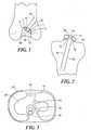
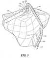
- FIGS. 1-3illustrate an exemplary use of guidance templates for performing ligament repair; in this case repair of the anterior cruciate ligament (ACL).
- FIG. 1shows a cross-sectional view of a femur and femoral guidance template.
- a guidance template 1is placed in the intercondylar notch region 5.
- At least one surface 10 of the template 1is sized and shaped to conform to (i.e., substantially matches) at least one or more portions of the notch 5 or the femur.
- the conforming shapeis derived from the patient's imaging study such as a CT scan or MRI scan.
- the template 1may be optionally placed against the trochlea and/or the femoral condyle (not shown).
- the mold 1includes an opening 20 and, optionally, metal sleeves 30, wherein the position, location and orientation of the opening 20 and/or the metal sleeves 30 determine the position and orientation of the femoral graft tunnel 40.
- FIG. 2shows a cross-sectional view of a tibia and tibial guidance template.
- a tibial template 50may be used to determine the location and orientation of the tibial tunnel 60.
- an opening 65 within the tibial mold 50can be designed to establish the position, angle and/or orientation of the tibial tunnel 160.
- the openingmay include optional metal sleeves 68.
- At least one surface of the tibial template 50substantially matches the surface of the tibia 75.
- the templatemay be matched to a tibial spine 80 wherein the tibial spine can help identify the correct position of the mold and help fix the template in place during the surgical intervention.
- the sleeves 30 and 68may be made of other hard materials, for example, ceramics.
- the femoral and/or tibial templatemay be optionally attached to the femoral or tibial articular surface during the procedure, for example using K-wires or screws.
- the entire templatecan optionally be made of hard materials, e.g. metal or ceramics.
- Templatesmay be designed to be compatible with any desired surgical technique.
- templatesmay be designed to be compatible with single bundle, double bundle or multiple bundle reconstruction techniques, tibial inlay techniques as well as other approaches.
- the devices used for such techniquesmay include specific characteristics to accommodate and facilitate such techniques.
- a figure-eight aperture or dual aperturesmay be included to accommodate both bundles.
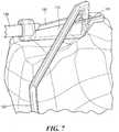
- FIGS. 4-7an instrument 100 for accurately and simply placing an ACL tunnel in a tibia during a procedure for the repair or replacement of the ACL is shown.
- the instrument 100has two components, a fitting 110 and a guide 120.
- Fitting 110is sized for placement at the end of an arthroscope 130 via coupling mechanism 140.
- Fitting 110also can include a viewing portal 150, a connection mechanism 160 and/or a registration surface 170.
- the portal 150is a hollow passage that allows the arthroscope to view the area of the procedure.
- Connection mechanism 160is an opening sized and shaped to register with guide 120 when instrument 100 is fully assembled. Although many embodiments are possible, connection mechanism extends entirely through fitting 110 to form a tunnel, as shown in FIGS. 6-7 .
- Registration surface 170is a surface designed as a negative to the specific corresponding portion of the surface of the tibia, preferably in the area of the tibial spine of the patient, such that the surface 170 mates to and registers with the corresponding tibial surface portion.
- the surface 170is individualized for a specific patient, and is a substantially negatively matching or conforming surface with the bone surface and conforms to that bone surface. Registration to the patient's anatomy can be achieved in other ways, for example, by utilizing a set of pins or notches that properly align the instrument by engaging the surface of the bone.
- the surface 170is sized to be as small as possible to facilitate placement in the area of the ACL procedure while being sufficiently large to allow an accurate registration with the patient's tibia such that the device accurately positions and orients the location and direction of the tibial tunnel.
- Guide 120includes an aiming tip 180, an arm 190 a pin housing 200, and a registration surface 210.
- Aiming tip 180is a pin sized and shaped to mate with connection mechanism 160.
- connection mechanism 160 and aiming tip 180is a close fit such that the connection assists in providing an accurate placement of instrument 100.
- the connectionscan include a threaded coupling mechanism, a snap fit, and/or other mechanism for connection.
- Registration surface 210is located at the end of pin housing 200.
- Surface 210is designed to be a negative of a specific corresponding portion of the surface of the tibia of the patient such that the surface 170 substantially negatively conforms (i.e., substantially matches) to and registers with a corresponding tibial surface portion.
- surface 210preferably is sized to be as small as possible to facilitate placement in the area of the ACL procedure while being sufficiently large to allow an accurate registration with the patient's tibia such that the device accurately positions and orients the location and direction of the tibial tunnel.
- Arm 190is sized and shaped to extend around the intervening portion of the head of the tibia, and connects and supports pin housing 200 and fitting 110.
- Considerable forcecan be generated by, for example, a surgeon creating (e.g., drilling) an ACL tunnel during such a procedure. Therefore, arm 190 is preferably made of a material capable of withstanding such forces with minimal deformation. Suitable materials for the components of instrument 100 include, for example, cobalt-chromium, titanium, or a sufficiently strong and rigid polymer material.
- Pin housing 200includes an opening 220 that guides a pin and/or drill during the procedure.
- a pin or bitcan be held captive in pin housing 200.
- the instrumentcan be assembled with surfaces 170 and 210 registered to the corresponding surface portions of the tibia.
- instrument 100provides a "catch feel" to the user.
- aiming tip 180extends through connection mechanism 160 and aiming tip 180 rests on the surface of the bone to define the location of the exit point of the tibial tunnel.
- the tibial tunnelis created through the head of the tibia exiting the outer surface of the tibia in the vicinity of fitting 110.
- the ACL pinis aimed at aiming tip 180.
- fitting 110can be part of, attached to or integrated with aiming tip 180 such that the entire instrument is a single piece, either integrated or assembled from several pieces during the procedure.
- the instrumentcan include three or more components, preferably the instrument has the same or fewer components as the number of portals used in the surgery, which is typically two.
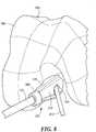
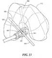
- a femoral instrument 300is shown. Femoral instrument 300 preferably is used in the same procedure as tibial instrument 100 to create a tunnel in the distal portion of the patient's femur to secure the opposite end of the ACL graft as the tibial tunnel created with tibial instrument 100.
- the instrument 300has one component, a fitting 310. Fitting 310 is sized for placement at the end of an arthroscope 130 via coupling mechanism 340. Fitting 310 also includes a viewing portal 350, a guide mechanism 360 and a registration surface 370 that substantially conforms to (i.e., substantially matches) the corresponding femoral surface (e.g., bone and/or cartilage surface).
- the portal 350is a hollow passage that allows the arthroscope to view the area of the procedure.
- Guide mechanism 360is an opening sized and shaped to allow the passage of an ACL guide and pin 370 to pass through fitting 310, as shown in FIG. 10 .
- the fit of guide 360preferably is close enough to allow the guide and pin 420 to pass through with minimal resistance while restraining any significant lateral or rotational movement that would cause the ACL tunnel in the femur to be misaligned.
- An ACL guide and pinmay be included as part of a femoral instrument.
- Registration surface 370is a surface designed as a negative to the specific corresponding portion of the surface of the femoral condyle, such that the surface 370 mates to and registers with the corresponding femoral surface portion.
- the surface 370is individualized for a specific patient, and is a substantially matching surface of the bone surface and conforms to that bone surface. Registration to the patient's anatomy can be achieved in other ways, for example, by utilizing a set of pins, clamps or notches that properly align the instrument by engaging the surface of the bone.
- the surface 370is sized to be as small as possible to facilitate placement in the area of the ACL procedure while being sufficiently large to allow an accurate registration with the patient's femur such that the device accurately positions and orients the location and direction of the femoral ACL tunnel.
- Suitable materials for the components of instrument 300include, for example, cobalt-chromium, titanium, or a sufficiently strong and rigid polymer material.
- instrument 310is placed on arthroscope 130 and registration surface 370 is placed against the corresponding surface of the femoral condyle 380.
- instrument 300When assembled and properly positioned on the femur, instrument 300 provides a close and secure feel to the user.
- a femoral tunnel 400, having opening 410,is created through the distal portion of the femur exiting the outer surface of the femur at exit 390.
- a femoral instrumentcan include a multi-piece design with multiple (two or more) registration surfaces similar to tibial instrument 100.
- a tibial instrumentcan have a single registration surface.
- the femoral instrumentuses a single registration surface to provide a simpler instrument that takes advantage of the ridge on the femoral condyle to provide a secure fit, while the tibial instrument includes multiple registration surfaces to provide a more secure fit over the relatively flatter and less complex geometries typically found on the tibial plateau.
- the femoral instrumentcan include three or more components, but preferably has no more components than the number of portals involved in the procedure.
- the femoral and tibial tunnelscan be created using a single instrument that provides for an alignment of both the tibial and femoral tunnel locations such that the tunnels can be created using one cut along a common axis.
- the tunnelsis created in a manner and orientation that reduces and/or eliminates the eccentricity of the tunnel openings that open into the joint cavity, such that the tunnel is circular or more circular in shape. Among other things, this helps reduce wear on the ACL graft at the edges of the openings, and is thought to be the geometry preferred by most doctors performing such procedures.
- the above examples discussed in conjunction with FIGS. 4-11involve a single-bundle technique.
- One potential drawback to the single-bundle techniqueis that the procedure may not reproduce the patient's native anatomy.
- the proceduredoes not reproduce the pre-existing ACL, which is formed of two bundles, the anteromedial (AM) and posterolateral (PL) bundles, each of which attaches in slightly different locations on the tibia and femur.
- the single-bundle methodmay result in a tunnel mismatch.
- tibial AM siteinstead of connecting the tibial AM site to femoral AM site and tibial PL site to femoral PL site, it may produce some kind of mismatch by connecting tibial PL site (B) to femoral AM site (A), or tibial PL site (B) to a high AM site (high).
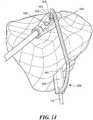
- a tibial instrument 600can be used in conjunction with (or separate from) femoral instrument 500 to create two tibial tunnels during a double-bundle ACL reconstruction procedure.
- Instrument 600has a structure and function similar to tibial instrument 100 discussed above, but, in addition to tip 610 with a registration surface 640, instrument 600 also has two guide components 645 and 650. Each guide component has a unique registration surface 660 and 670 respectively and as well as aiming tips 680 and 690.
- tip 610includes two openings 620 and 630 for creating two tibial tunnels during the procedure.
- the first guide component 645is optionally attached to tip 610 by placing aiming tip 680 in opening 620.
- Patient-specific registration surfaces 660 and 700are registered to the corresponding surface of the tibia as shown.
- the length, shape and/or orientation of instrument 600can be adapted based on imaging data, or can be adjusted intraoperatively so that guide components 645 and 650 can be simultaneously aligned with openings 620 and 630 respectively.
- the first tunnelis then created using pin 710 (or other appropriate device such as a drill).
- the first guide component 640is removed and the second guide component 650 is attached to tip 610 by placing aiming tip 690 in opening 630.
- Patient-specific registration surfaces 670 and 640are registered to the corresponding surface of the tibia as shown.
- the second tunnelis then created using pin 720.
- either or both of the femoral instrument 500 and the tibial instrument tip 600can each include a single opening to create one tunnel, and a second companion component can be included with a differently oriented opening to create the second tunnel.
- one tibial tunnelcan be created with two femoral tunnels or vice versa.
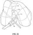
- instrument 700functions in a manner similar to instrument 500 discussed above. However, instrument 700 additionally includes a larger bore section 710 that provides for an enlarged section 720 of tunnel 730 that has a larger diameter than the remainder of tunnel 730 to accommodate a larger ACL graft.
- the larger bore section 710can optionally be formed by drilling out additional bone after the narrower tunnel 720 is initially formed.
- the tunnelscan be created by using pins placed in a first tunnel to create additional referencing and stability for the drilling of later tunnels, either on the same portion of the bone, e.g., first and second femoral tunnels, or on different portions of bone, e.g., first tibial tunnel and first femoral tunnel, second femoral tunnel and first tibial tunnel, first and second tibial tunnels and first and/or second femoral tunnels, or another combination of tunnels.
- the placement of the location of the AM and PL portions of the double bundle ACL graftcan be determined using the patient's existing anatomical landmarks and/or combinations of landmarks.
- the bony ridge between the attachment sites for the native AM and PL portions of the patient's ACLcan be located using a CT scan, and can additionally be used in combination with one or more average offset values, for example from a ridge of the trochlear groove to one or both of the AM and PL attachment sites.
- the instrumentscan be placed on the arm of a robot to help register the position of the robot during surgery, which may significantly reduce the amount of preparation time for robot-assisted procedures.
- PCLposterior cruciate ligament
- the initial treatment of partial PCL injuriescan include protected weight bearing, the use of a knee immobilizer or brace with drop-lock hinges, and/or a quadriceps and triceps rehabilitation program to counteract posterior tibial subluxation.
- the nonoperative course for isolated, complete tears of the PCL (grade III)does not have a high success rate.
- many of these injuriesdo not heal, and over time these patients can develop symptoms secondary to increased shear stresses to the articular cartilage, especially in the medial and patellofemoral compartments. Thus, surgery frequently is the recommended option for these patients, especially if they continue to be symptomatic despite maximizing physical therapy.
- Autologous tissuesinclude patellar, hamstring, or quadriceps tendon. Achilles tendon, patellar tendon, and tibialis anterior tendon are the most commonly used allograft tissues.
- Achilles tendon, patellar tendon, and tibialis anterior tendonare the most commonly used allograft tissues.
- Several studieshave documented by arthroscopy and histologic methods that the transplanted allograft tendons revascularize, undergo cellular repopulation and reach maturity just as autograft tissue does, although this process may take longer with allograft tissue.
- An Achilles tendon allograftis often preferred because of its high tensile strength, shorter operating time, ease of passage, and lack of donor-site morbidity in an already compromised knee.
- Additional benefitsinclude its exceptional size and length and bony attachment at one end, making it quite versatile when compared to other graft options.
- Multiple methods of fixationalso exist, including metal and bio-interference screws, buttons, cortical screws and soft tissue washers, or staples. Use of a screw and soft tissue washer is preferred when securing soft tissue to bone in most instances, as this has been shown to be the most stable fixation.
- Biomechanical studiessupport reconstruction of the anterolateral bundle when performing a single-bundle technique.
- Anterior placement of the femoral tunnel in the anatomic footprinthas been shown to restore normal knee laxity better than isometric graft placement.
- placement of the osseous tunnelscan be important to the success of the procedure. Variations in tibial tunnel placement can affect graft behavior to a lesser degree than femoral tunnel placement variations.
- the position in which non isometric graft is tensioned and fixedcan have a significant effect on knee mechanics.
- the single-bundle techniquewas developed to reconstruct the anterolateral bundle because of its larger size and greater biomechanical properties when compared with the posteromedial bundle.
- single tibial and femoral tunnelscan be utilized. Reproduction of the normal anatomy may be the ideal location with anterior placement of the tunnel in the anatomic anterolateral bundle footprint of the femur. Good results have been reported with this approach along with tensioning of the graft in 90 degrees of knee flexion with an anterior drawer force.
- transtibial drilling techniques from the anteromedial tibiacan create an unwanted tunnel curve.
- Techniqueshave been developed to limit this graft angulation using a posterolateral tibial tunnel as well as the tibial inlay technique described below.
- Double-bundle reconstruction techniqueshave been introduced in an attempt to reproduce more accurately the complex functional anatomy of the PCL. It has been shown in cadaver studies that double-bundle PCL reconstruction may more closely restore normal knee biomechanics throughout its full range of motion. While traditional single-bundle reconstruction restores knee biomechanics at mid- to high knee flexion angles, there can be residual laxity when the knee is near full extension. Biomechanical studies have shown the addition of the posteromedial bundle reduced posterior tibial translation in knee flexion, as well as extension, suggesting that this bundle can serve an important role throughout knee flexion. Although technically challenging, double-bundle reconstruction has become a preferred surgical technique in chronic PCL deficiency because of its improved restoration of normal knee mechanics.
- the tibial inlay techniquewas initially introduced to circumvent the issues of bone plug passage through the long tibial tunnel and potential abrasion at the posterior tibial exit point. It can also facilitate protection of the neurovascular structures. Utilization of the posterior approach to the tibial insertion of the PCL as can simplify the posterior exposure. The technique has been utilized most commonly with patella tendon autograft, but recently it has been described in use with a double-bundle Achilles allograft.
- the combined PCL-(posterolateral structures) PLS injuryis one of the most complicated knee injury patterns that an orthopedic surgeon may experience.
- substantial posterior translation, external rotation, and varus openingmay all be present at differing angles of knee flexion.
- This combinationcreates a complex surgical dilemma that usually necessitates the surgeon having more than one surgical plan.
- Many techniques of reconstructionhave been devised, including arcuate ligament advancement, biceps tenodesis, and popliteofibular ligament reconstruction with allograft or autograft tissue.
- Chronic cases of posterolateral instabilitydemonstrate tissue redundancy and excessive scarring posterior to the LCL, making identification of the particular structures of the popliteus complex difficult.
- the timing of surgical treatment of the injured PLSis significant, with acute repairs consistently giving more favorable results than reconstruction of chronic injuries.
- Chronic PCL injuries involving the PLSare even more surgically challenging. If an injury to the PLS is ignored or goes unrecognized, repair or reconstruction of other ligaments may have a significant risk of failure due to chronic repetitive stretching of the reconstruction.
- Surgical treatment of PLS injuries in the chronic injury settingis centered on reconstruction rather that repair of deficient structures.
- Anatomic reconstruction of the popliteofibular ligamentis preferred and, if needed, the LCL. If varus malalignment or a lateral thrust exists, a proximal tibial osteotomy may be performed to correct the alignment. Although the osteotomy may be performed in conjunction with the PLS reconstruction, the operation may be staged since the osteotomy alone may alleviate the patient's symptoms, thereby avoiding further surgical intervention.
- PCL tibial guidesare designed with protective aiming arms to mitigate the likelihood of such an injury during surgery. Drilling through the posterior cortex of the tibial tunnel by hand can be an important safety measure for the transtibial tunnel technique. A posteromedial safety incision is another strategy that can reduce this risk.
- the tibial inlay techniqueby eliminating the transtibial tunnel, is another way to limit the risk of neurovascular injury.
- guidance templatesmay be designed for single as well as double bundle surgical techniques.
- a guidance templatemay be created with a position, orientation and/or shape of the template or associated reference points or guide apertures for surgical instruments that help create a femoral tunnel in a desired location, for example, in the location of the anatomic origin of the ligament.
- the template and any related reference points or guide apertures or linkagesmay be designed and placed so that an anterior placement of the femoral tunnel in the anatomic footprint is performed. A more anterior placement of the femoral tunnel can, optionally, restore normal knee laxity better than isometric graft placement.
- the guidance templatesmay be designed so that optimal tension is achieved not only in knee extension but also in knee flexion, particularly at ninety degrees of knee flexion.
- the origin and the insertion of the PCLmay be identified pre-operatively on the scan, either by identifying residual fiber bundles or by identifying the underlying anatomic landmarks.
- the distance between the origin and the insertionmay thus be determined in the extension and can be simulated (e.g., virtually simulated using a patient-specific model of the patient's joint) for different flexion degrees or other articular positions.
- Kinematic modeling and simulation as well as finite element modelingcan be performed for further optimization, as outlined above for ACL repair where similar principles apply.
- Femoral and tibial tunnel placement and orientationmay then be optimized in order to achieve an isometric or near isometric ligament placement. Intraoperative adjustments are feasible as described in the foregoing embodiments.
- a guidance templatemay also be designed both on the femoral as well as on the tibial side using double bundle reconstruction techniques.
- the femoral or tibial templatecan include or incorporate links or can have attachable linkages so that a femoral tunnel can be created and cross referenced with a tibial tunnel, or a tibial tunnel can be created and cross referenced to a femoral tunnel.
- the templatesmay include stops for drills and reaming devices or other surgical instruments, for example, to protect popliteal neurovascular structures.
- the templatesmay include extenders or flanges to serve as tissue retractors as well as tissue protectors.
- guidance templatesare applicable to any type of ligament or tendon repair, not only ACL and PCL repair, and can provide reproducible, simple intraoperative location of intended attachment sites or tunnels.
- the size, shape, orientation and position of the guidance templatesmay be individualized and optimized for articular anatomy, as well as the biomechanical situation, and may incorporate not only a shape that conforms to a corresponding articular shape on the patient's anatomy, but also can include patient-specific anatomic lines, anatomic planes, biomechanical lines or biomechanical planes (e.g., marked on the templates), as well as portions or all of the shape of devices or anchors or instruments to be implanted or used during implantation or used during surgical repair of a ligament or tendon tear.
- the techniques described hereinalso allow for kinematic modeling and simulation, finite element modeling, all optionally integrated with the patient's imaging data, as well as intraoperative assessment of graft function and related adjustments.
- FIGS. 18 and 19illustrate an alternative design of a cutting block 820 that provides additional structures 860 to protect, for example the cruciate ligaments, from being cut during a surgical procedure.
- additional structurescan be in the form of indented guides 860, as shown in FIG. 19 or other suitable structures.
- a devicecan include an inner mold 810 configured such that the upper surface forms a convex dome 850 that fits with a concave well 852 provided on the interior surface of the cutting block 820.
- the various components usedcan be small enough to be inserted via an endoscope, arthroscopy portal or other device that provides a passage to access the joint.
- the tools and devicescan be designed in segments or pieces, preferably small segments or pieces, which can be assembled at the location of the surgical procedure in the body once inserted into the body.
- Such devicesmay have locking or other mechanisms (such as mechanical or magnetic couplings) that allow the device to be assembled.
- a template for the placement of a distal tunnelcan be dispatched via a proximal tunnel that has already been created during the procedure. For example, if a tibial tunnel has been created, a template can be placed to create a femoral tunnel via the tibial tunnel. As another example, the reverse situation is also possible. If a femoral tunnel has been created, a template can be placed to create a tibial tunnel via the femoral tunnel. The first tunnel can be placed beginning either from within the joint space moving outward or from outside the joint space moving inward toward the opposing articular surface.
- This conceptis applicable towards any type of ligament repair, not only ACL and PCL.
- the tools and devices or segments and piecesmay be inserted through a bone tunnel that extends into the joint.
- Such a devicemay preferably be constructed of several small components that are dispatched through a portal or incision or a bone tunnel and assembled at the location of the distal femoral articular surface.
- Various examplescan include a multi-component device that is assembled to register with (e.g., have a surface that substantially matches) a portion of one articular surface, a multi-component device that is assembled to register with a portion of one articular surface and is linked to a tunnel opposing the articular surface to which the device registers, a multi-component device that is assembled to register with a portion of both articular surfaces, and a multi-component device that is assembled to register with a portion of both articular surfaces and is linked to the tunnel opposing the articular surface to which the device registers.
- Other examplesare possible.
- the template or components thereofcan also be of expandable design. Such expandable designs can optionally utilize Nitinol or other "memory-like" materials.
- the template or tool or device and componentscan be small in shape or cross-section prior to insertion and at the time of insertion. Once inserted, the template or tool or device and components can expand. The expansion can be active, e.g., in the case of Nitinol, or passive, e.g., via secondary devices that help expand the device or tool.
- one or more surface of the devicecan be patient matched, for example using the imaging data. Alternatively, predefined dimensions or shapes or surfaces can be selected based on the imaging data to achieve an optimal fit with the patient's articular surface(s) intraoperatively.
- the methods and devices described hereincan be used to locate and harvest grafts for semitendinosus and/or gracilis autograft (hamstrings).
- the site of such graftscan be difficult to locate precisely, and the difficulty can cause some surgeons to avoid the procedure altogether.
- the siteis generally approximately 5cm distal from the anterior tibial plateau eminence.
- a surgical device based on patient-specific informationcan provide the precise location of such a graft and improve the ability of surgeons to perform such procedures as well as the reliability of the procedure itself and the associated patient outcome.
- Devices and techniquescan be employed to determine the size of grafts needed for ligament repair. For example, patient-specific information can be employed to determine the size of the native cruciate ligament in the knee, or other ligaments. Even if torn or stretched, the size of the ligament can be estimated from the joint spacing, bone structure, and the ligament itself either manually or, alternatively, partially or entirely with the assistance of automated software. For this purpose, kinematic simulations can be employed or integrated with the imaging data. These simulations can, for example, determine graft length for different flexion and extension angles. Moreover, different insertions and origins can be determined and optimized based on available grafts and graft lengths.
- Devices and methodscan be employed to observe the size of hamstring tissue available to serve as a graft for the repair of the ACL, PCL or other ligaments. Such embodiments are advantageous in part, because they help ensure that the size of the graft, e.g., length and/or diameter.
- Patient-specific surgical instruments or other patient-specific devicescan be placed and or used via a robotic device or other similar devices.
- Patient specific surgical instrumentscan be attached to a limb or a joint surface substantially conforming to the patient's anatomy.
- the patient specific surgical instrumentcan then be linked to a robot, e.g., by mechanical, magnetic, electronic or wireless means.
- the position of the patient specific surgical instrumentcan help cross-reference the location of the extremity or the articular or other patient geometry and the robot or any surgical instruments attached to the robot or operated via the robot in a fast and time efficient manner.
- Patient specific surgical instrumentscan also be used for cross-referencing the anatomy for surgical navigation systems. In this manner, time-consuming steps of registering a robot or navigation system relative to the patient's anatomy can be greatly accelerated, thereby reducing the time needed for the procedure.
- Sensorscan be placed on surgical guides and other instruments, for example, to assist with proper registration of the guides to an articular surface or otherwise assist in steps of the procedure. Similarly, sensors can be used in conjunction with an endoscope or arthroscopic portal to provide information with respect to the placement and function of the surgical guide or other device. Sensors can be optical or radiofrequency based. Sensors can be wireless. Sensors can also include pressure probes and enable pressure measurements.
- the surgical guidemay include an aiming device or other device to assist in the placement of the device or in other steps of the procedure.
- a devicecan, for example, assist with the placement of the distal and proximal tunnels of an ACL or PCL reconstruction.
- a patient-specific templatecan match or register a bone characteristic or marker, for example, the notch of the knee joint or an osteophyte, to assist with proper placement and alignment.
- the direction vectors of one or more bone tunnelscan be positioned to facilitate proper alignment and placement of the tunnels.
- a tibial tunnelmay be aligned towards the femur using a medial approach in which the tibial tunnel is aligned with a lateral directional component relative to the notch. This may improve resistance and/or rotational stability. This also may allow a more circular aperture with less angle at the opening of the tunnel on the articular surface.
- the vectors of the tunnelscan be chosen to navigate around structures, for example, deformities in the bone, hardware from previous surgeries, arthroplasty implants, devices implanted at the time of the ligament procedure.
- a patient-specific deviceis placed posteriorly to protect the guide pin that the drill passes over during the surgical procedure.
- the alignment of the tunnelscan be established by taking the joint through flexion and extension and ensuring that the template is registered and aligned in flexion, extension, and/or in interim positions. This registration and / or alignment can occur on one articular surface or by referencing both articular surfaces.
- the instrumentation for placementcan be virtual.
- a video feed from an endoscope inserted into the surgical area, or a video camera or other sensor devicecan otherwise placed at the surgical site during a procedure.
- the video feedis processed to provide the surgeon with the video information normally viewed, and is additionally processed in conjunction with imaging data (such as CT or MRI data) created prior to the surgery.
- a computer or similar deviceprocesses the information and compares the view from the endoscope to the imaging data to determine the proper placement of the associated tunnel or otherwise guides other and additional steps during the procedure.
- a visual markcan be displayed showing the proper placement of a tunnel and/or an instrumentation device.
- Further sensorscan be included, for example, on a cutting or drilling tool, to virtually determine and/or verify the proper orientation of the tunnel.
- imaging techniquespreferably employ conventional methods of x-ray imaging and processing, x-ray tomosynthesis, ultrasound including A-scan, B-scan and C-scan, computed tomography (CT scan), magnetic resonance imaging (MRI), optical coherence tomography, single photon emission tomography (SPECT) and positron emission tomography (PET) within the skill of the art.
- CT scancomputed tomography
- MRImagnetic resonance imaging
- SPECTsingle photon emission tomography
- PETpositron emission tomography
- imaging techniquesare explained fully in the literature and need not be described herein.
- measurements of the size of an anatomical areafor example, an area of diseased cartilage or an area of cartilage loss, measurements of cartilage thickness and/or curvature of cartilage or bone can be obtained intraoperatively during arthroscopy or open arthrotomy.
- Intraoperative measurementscan, but need not, involve actual contact with one or more areas of the articular surfaces.
- Devices suitable for obtaining intraoperative measurements of cartilage or bone or other articular structures, and to generate a topographical map of the surfaceinclude but are not limited to, Placido disks, optical measurements tools and device, optical imaging tools and devices, and laser interferometers, and/or deformable materials or devices.
- Placido disksinclude but are not limited to, Placido disks, optical measurements tools and device, optical imaging tools and devices, and laser interferometers, and/or deformable materials or devices.
- Ligaments, menisci and other articular structurescan be displayed in 2-D and 3-D.
- various parametric surface representationssee, for example Foley, J.D. et al., Computer Graphics: Principles and Practice in C; Addison-Wesley, 2nd edition, 1995 ).
- the 2-D or 3-D representations of the cartilage and/or subchondral bone and other anatomic structures and the articular repair systemcan be merged into a common coordinate system.
- the articular repair systemincluding surgical tools and instruments, molds, in situ repair systems, and/or other components, can then be placed at the desired implantation site.
- the representations of the cartilage, subchondral bone, ligaments, menisci and other anatomic structures and the articular repair systemare rendered into a 2-D or 3-D image, for example application programming interfaces (APIs) OpenGL® (standard library of advanced 3-D graphics functions developed by SGI, Inc.; available as part of the drivers for PC-based video cards, for example from www.nvidia.com for NVIDIA video cards or www.3dlabs.com for 3Dlabs products, or as part of the system software for Unix workstations) or DirectX® (multimedia API for Microsoft Windows® based PC systems; available from www.microsoft.com) .
- APIsapplication programming interfaces
- OpenGL®standard library of advanced 3-D graphics functions developed by SGI, Inc.; available as part of the drivers for PC-based video cards, for example from www.nvidia.com for NVIDIA video cards or www.3dlabs.com for 3Dlabs products, or as part of the system software for Unix workstations
- DirectX®
- the 2-D or 3-D imagecan be rendered or displayed showing the cartilage, subchondral bone, ligaments, menisci or other anatomic objects, and the articular repair system from varying angles, e.g. by rotating or moving them interactively or non-interactively, in real-time or non-real-time.
- Surgical assistancecan be provided by using a device applied to the outer surface of the articular cartilage or the bone, including the subchondral bone, in order to match the alignment of the articular repair system and the recipient site or the joint.
- the devicecan be round, circular, oval, ellipsoid, curved or irregular in shape.
- the shapecan be selected or adjusted to match or enclose an area of diseased cartilage or an area slightly larger than the area of diseased cartilage or substantially larger than the diseased cartilage.
- the areacan encompass the entire articular surface or the weight bearing surface.
- Such devicesare typically preferred when replacement of a majority or an entire articular surface is contemplated.
- Mechanical devicescan be used for surgical assistance (e.g., surgical tools), for example using gels, molds, plastics or metal.
- One or more electronic images or intraoperative measurementscan be obtained providing object coordinates that define the articular and/or bone surface and shape. These objects' coordinates can be utilized to either shape the device, e.g. using a CAD/CAM technique, to conform to (i.e., substantially match or register) a patient's articular anatomy or, alternatively, to select a typically pre-made device that has a good fit with a patient's articular anatomy.
- the devicecan have a surface and shape that substantially matches all or portions of the articular cartilage, subchondral bone and/or other bone surface and shape.
- the devicecan include, without limitation, one or more cut planes, apertures, slots and/or holes to accommodate surgical instruments such as drills, reamers, curettes, k-wires, screws and saws.
- the moldmay be designed to rest on bone or cartilage outside the area to be worked on, e.g. cut, drilled, and/or worked on in other ways. In this manner, multiple surgical steps can be performed using the same mold. For example, in the knee, the mold may be stabilized against portions of the intercondylar notch, which can be selected external to areas to be removed for total knee arthroplasty or other procedures. The mold may be affixed to the underlying bone, for example with pins or drills, and/or other devices.
- the moldmay rest on the articular cartilage.
- the moldmay rest on the subchondral bone or on structures external to the articular surface that are within the joint space or on structures external to the joint space.
- an imaging test demonstrating the articular cartilagecan be used in one embodiment. This can, for example, include ultrasound, spiral CT arthrography, MRI using, for example, cartilage displaying pulse sequences, or MRI arthrography.
- an imaging test demonstrating the subchondral bonee.g. CT or spiral CT, can be used and a standard cartilage thickness can be added to the scan.
- the standard cartilage thicknesscan be derived, for example, using an anatomic reference database, age, gender, and race matching, age adjustments and any method known in the art or developed in the future for deriving estimates of cartilage thickness.
- the standard cartilage thicknessmay be uniform across one or more articular surfaces or it can change across the articular surface.
- the moldmay be adapted to rest substantially on subchondral bone.
- residual cartilagecan create some offset and inaccurate result with resultant inaccuracy in surgical cuts, drilling and the like.
- the residual cartilageis removed in a first step in areas where the mold is designed to contact the bone and the subchondral bone is exposed. In a second step, the mold is then placed on the subchondral bone.
- osteophytes or other deformitiesmay be removed by the computer software prior to generation of the mold.
- the softwarecan automatically, semi-automatically or manually with input from the user simulate surgical removal of the osteophytes or other deformities, and predict the resulting shape of the joint and the associated surfaces.
- the moldcan then be designed based on the predicted shape. Intraoperatively, these osteophytes or other deformities can then also optionally be removed prior to placing the mold and performing the procedure. Alternatively, the mold can be designed to avoid such deformities.
- the moldmay only be in contact with points on the articular surface or external to the articular surface that are not affected or involved by osteophytes.
- the moldcan rest on the articular surface or external to the articular surface on three or more points or small surfaces with the body of the mold elevated or detached from the articular surface so that the accuracy of its position cannot be affected by osteophytes or other articular deformities.
- the moldcan rest on one or more tibial spines or portions of the tibial spines. Alternatively, all or portions of the mold may be designed to rest on osteophytes or other excrescences or pathological changes.
- the templatemay be a mold that can be made of a plastic or polymer.
- the moldmay be produced by rapid prototyping technology, in which successive layers of plastic are laid down, as know in the art.
- the template or portions of the templatecan be made of metal.
- the moldcan be milled or made using laser based manufacturing techniques.
- the templatemay be casted using rapid prototyping and, for example, lost wax technique. It may also be milled. For example, a preformed mold with a generic shape can be used at the outset, which can then be milled to the patient specific dimensions. The milling may only occur on one surface of the mold, preferably the surface that faces the articular surface. Milling and rapid prototyping techniques may be combined.
- Curable materialsmay be used which can be poured into forms that are, for example, generated using rapid prototyping.
- liquid metalmay be used.
- Cured materialsmay optionally be milled or the surface can be further refined using other techniques.
- Metal insertsmay be applied to plastic components.
- a plastic moldmay have at least one guide aperture to accept a reaming device or a saw.
- a metal insertmay be used to provide a hard wall to accept the reamer or saw. Using this or similar designs can be useful to avoid the accumulation of plastic or other debris in the joint when the saw or other surgical instruments may get in contact with the mold.
- Other hard materialscan be used to serve as inserts. These can also include, for example, hard plastics or ceramics.
- the molddoes not have metallic inserts to accept a reaming device or saw.
- the metal inserts or guidesmay be part of an attached device that is typically in contact with the mold.
- a metallic drill guide or a metallic saw guidemay thus, for example, have metallic or hard extenders that reach through the mold thereby, for example, also stabilizing any devices applied to the mold against the physical body of the mold.
- the templatemay not only be used for assisting the surgical technique and guiding the placement and direction of surgical instruments.
- the templatescan be utilized for guiding the placement of a graft, implant or implant components.
- One or more templatescan be used during the surgery. It is also possible to make templates that are designed to fit to a bone or portions of a joint after the surgeon has already performed selected surgical procedures, such as cutting, reaming, drilling, and/or other procedures.
- the templatecan account for the shape of the bone or the joint resulting from these procedures.
- the biomechanical and/or anatomic axesmay be derived using above-described imaging techniques including, without limitation, a standard radiograph, including a load bearing radiograph, for example an upright knee x-ray or a whole leg length film (e.g., hip to foot). These radiographs may be acquired in different projections, for example anteroposterior, posteroanterior, lateral, oblique, and/or other projections.
- the biomechanical and anatomic axesmay also be derived using other imaging modalities such as CT scan or MRI scan, a CT scout scan or MRI localized scans through portions or all of the extremity, either alone or in combination, as described in above embodiments.
- CT scan or MRI scana CT scout scan or MRI localized scans through portions or all of the extremity, either alone or in combination, as described in above embodiments.
- a spiral CT scanmay be obtained through the knee joint.
- the spiral CT scan through the knee jointserves as the basis for generating the negative contour template(s)/mold(s) that are affixed to portions or all of the knee joint.
- Additional CT or MRI scansmay be obtained through the hip and ankle joint. These may be used to define the centroids or centerpoints in each joint or other anatomic landmarks, for example, and then to derive the biomechanical and other axes.
- the biomechanical axismay be established using non-image based approaches including traditional surgical instruments and measurement tools such as intramedullary rods, alignment guides and also surgical navigation.
- traditional surgical instruments and measurement toolssuch as intramedullary rods, alignment guides and also surgical navigation.
- optical or radio frequency markerscan be attached to the extremity.
- the lower limbmay then be rotated around the hip joint and the position of the markers can be recorded for different limb positions.
- the center of the rotationcan determine the center of the femoral head. Similar reference points may be determined in the ankle joint and/or other locations.
- the position of the templates or, more typically, the position of surgical instruments relative to the templatesmay then be optimized for a given biomechanical load pattern, for example in varus or valgus alignment.
- the position of the surgical instrumentsmay be optimized relative to the molds and the cuts can be placed to correct underlying axis errors such as varus or valgus malalignment or ante- or retroversion.
- a physical templateUpon imaging, a physical template can be generated.
- the templatecan be used to perform image guided surgical procedures such as partial or complete joint replacement, articular resurfacing, or ligament repair.
- the templatemay include reference points or opening or apertures for surgical instruments such as drills, saws, burrs and the like.
- openings or receptacles in said template or attachmentscan be adjusted to account for at least one axis.
- the axiscan be anatomic or biomechanical, for example, for a knee joint, a hip joint, an ankle joint, a shoulder joint or an elbow joint.
- Angle and distance measurements and surface topography measurementsmay be performed in these one or more, preferably two or more, preferably three or more multiple planes, as desired. These angle measurements can, for example, yield information on varus or valgus deformity, flexion or extension deficit, hyper or hypo--flexion or hyper- or hypo-extension, abduction, adduction, internal or external rotation deficit, or hyper-or hypo-abduction, hyper- or hypo-adduction, hyper- or hypo- internal or external rotation.
- more than one drilling, cut, boring and/or reaming or other surgical interventionis performed for a particular treatment such as the placement of a joint resurfacing or replacing implant, or components thereof.
- These two or more surgical interventionse.g., drilling, cutting, reaming, sawing
- the guidance template or attachments or linkages theretoinclude two or more openings, guides, apertures or reference planes to make at least two or more drillings, reamings, borings, sawings or cuts in relationship to a biomechanical axis, an anatomical axis, an implant axis or other axis derived therefrom or related thereto.
- the toolcan be designed so that the instrument controls the depth and/or direction of the drill, i.e. , the drill cannot go any deeper into the tissue than the instrument allows.
Landscapes
- Health & Medical Sciences (AREA)
- Life Sciences & Earth Sciences (AREA)
- Engineering & Computer Science (AREA)
- Surgery (AREA)
- General Health & Medical Sciences (AREA)
- Animal Behavior & Ethology (AREA)
- Veterinary Medicine (AREA)
- Public Health (AREA)
- Biomedical Technology (AREA)
- Heart & Thoracic Surgery (AREA)
- Orthopedic Medicine & Surgery (AREA)
- Oral & Maxillofacial Surgery (AREA)
- Medical Informatics (AREA)
- Molecular Biology (AREA)
- Nuclear Medicine, Radiotherapy & Molecular Imaging (AREA)
- Dentistry (AREA)
- Physics & Mathematics (AREA)
- Rheumatology (AREA)
- Cardiology (AREA)
- Vascular Medicine (AREA)
- Transplantation (AREA)
- Geometry (AREA)
- Manufacturing & Machinery (AREA)
- Robotics (AREA)
- Physiology (AREA)
- Biophysics (AREA)
- Pathology (AREA)
- Prostheses (AREA)
- Surgical Instruments (AREA)
Description
- The embodiments described herein relate to orthopedic methods for surgical procedures related to joint ligaments. Some of the embodiments include surgical molds designed from patient-specific data to facilitate the repair or replacement of such ligaments. The closest prior art is document
US 2008/0243127 A1 , which defines the preamble ofclaim 1. - There are a growing number of cases of surgical procedures performed to repair, reconstruct, replace, or otherwise treat ligaments, such as anterior cruciate ligaments ("ACL") and posterior cruciate ligaments ("PCL"). However, surgeons performing such procedures have difficulty, for example, in properly placing grafts or performing other surgical steps.
- In the case of ACL and PCL grafts, placement of the associated tunnels to house the grafts can be difficult. For example, grafts placed too far anteriorly on the femur are reportedly a common cause of failure in ACL reconstruction. Some studies suggest that more precise placement of the femoral tunnel would improve kinematics. More accurate placement of the tibial and femoral tunnels may reduce the incidence of graft failure and may reduce long-term degeneration observed after reconstruction. There are other difficulties associated with such procedures. For example, in some cases it can be difficult to locate the tissue from which a graft is to be extracted, or to properly size the graft.
- The invention is defined in
claim 1 and provides a method for performing surgical procedures to replace, repair or otherwise treat ligaments associated with bone joints. - In one aspect, certain embodiments relate to a method for ligament repair includes obtaining electronic image data of at least one surface associated with a ligament. A first template is created based, at least in part, on the image data. The first template has at least one contact surface that conforms to at least a portion of the surface. The first template includes at least one guide for directing movement of a surgical instrument involved with the ligament repair.
- In some embodiments, the ligament may be an anterior cruciate ligament or a posterior cruciate ligament. The method further includes determining a tunnel site for a ligament graft. Determining the tunnel site may include identifying an origin of the ligament on a first articular surface and an insertion position onto a second articular surface opposing the first articular surface. Determining the tunnel site may include identifying at least one of a bony landmark and a remainder of a ligament based on the image data. The surface may be adjacent to the tunnel site, or a non-weight bearing surface. The first template includes one or more pin and/or drill guide apertures, the method further including positioning the template such that the at least one contact surface contacts the at least a portion of the surface, and creating (e.g., drilling) a ligament tunnel, for example, wherein the drilling is guided by the drill guide aperture. At least one of the shape, position and orientation of a pin and/or drill guide aperture on the first template may be based, at least in part, on a distance of the tunnel to adjacent cortical bone. The drill guide aperture may include a stop, such that a desired drill depth is obtained. The image data may be obtained preoperatively. The image data may be obtained by a CT scan or an MRI scan. The image data may be obtained in joint flexion, joint extension, joint abduction, joint adduction, and/or joint rotation. The method may further include identifying a graft harvest site based on the image data, and using the first template to guide harvesting of at least one of ligament and bone from the graft harvest site. The method may further include cross-referencing a second template to the first template to align position of the second template on a second surface associated with the ligament, the second template including at least one guide, and directing movement of the instrument using the at least one guide of the second template relative to said guide. The first and second surfaces may be opposing articular surfaces. The first surface may be a femoral surface and the second surface may be a tibial surface. The first template may include a tissue retractor. The tissue retractor may be a flange or an extender on the template. The template may be used for single bundle or a double bundle ligament reconstruction.
- According to the invention, the method further includes obtaining electronic image data of the joint and determining a shape of the at least one contact surface of the first template based, at least in part, on electronic image data. Stabilizing may include using k-wires, a screw, an anchor, and/or a pin or drill bit left in place on the joint. Stabilizing may include positioning the contact surface on at least one or more concavities and convexities on the joint. Stabilizing may include positioning the contact surface on at least one concavity and at least convexity on the joint. Stabilizing may include positioning the contact surface, at least partially, on an arthritic portion of the joint. Stabilizing may include positioning the contact surface, at least partially, on an interface between a normal and an arthritic portion of the joint. Stabilizing may include positioning the contact surface, at least partially, against an anatomic feature. The anatomic feature may be a trochlea, an intercondylar notch, a medial condyle and a lateral condyle, a medial trochlea and a lateral trochlea, a medial tibial plateau and a lateral tibial plateau, a fovea capities, an acetabular fossa, a tri-radiate cartilage, an acetabular wall, or an acetabular rim. Positioning the contact surface on the surface of the joint may include positioning the contact surface on, at least partially, a normal portion of the joint. Determining the position of the guide on the template may be based, at least in part, on ligament balancing and/or to optimize at least one of flexion and extension gap. The method may further include adjusting the position of the guide relative to the joint intraoperatively using, for example, a spacer, a ratchet device, and a pin that allows rotation.
- Determining the desired femoral component rotation may include measuring one or more anatomic axes and/or planes relevant to femoral component rotation. The one or more anatomic axes and/or planes may include a transepicondylar axis, the Whiteside line, and/or the posterior condylar axis. The guide may direct a femoral cut, the method further comprising rotating the template so that the femoral cut is parallel to a tibial cut with substantially equal tension medially and laterally applied from medial and lateral ligaments and soft tissue.
- Determining the desired tibial component rotation may include measuring one or more anatomic axes and/or planes relevant to tibial component rotation. The one or more anatomic axes and/or planes may include an anteroposterior axis of the tibia and/or the medial one-third of the tibial tuberosity. The guide may direct a femoral cut, the method further comprising rotating the template so that the femoral cut is parallel to a tibial cut with substantially equal tension medially and laterally applied from medial and lateral ligaments and soft tissue.
- A method for joint arthroplasty may include providing a template that includes at least one surface for engaging a surface of a joint based, at least in part, on substantially isotropic input data. The surface can substantially match (i.e., conform to or register) one or more portions of the joint surface or of the entire joint surface. The template can include at least one guide for directing movement of a surgical instrument.
- The input data can be acquired using fusion of image planes, or substantially isotropic MRI and spiral CT.
- In any of the embodiments and aspects described herein, the joint can be, without limitation, a knee, shoulder, hip, vertebrae, elbow, ankle, foot, toe, hand, wrist or finger.
- Some embodiments can include various additional features such as an intraoperative adjustment of various dimensions, orientations or relative locations. For example, the instruments can position one or more tunnels, while tunnel orientation can be determined intraoperatively based on graft length and location. The instruments can also position an entry for a tunnel and determine tunnel orientation, with optional intraoperative adjustment.
- A first tunnel can be used to connect to and or provide a reference for a second tunnel associated with the same articular surface or associated with a different articular surface.
- The kinematics of the joint can be evaluated and/or improved, for example, during the procedure or prior to the procedure, e.g., by evaluating images and/or models of the joint. For example, a simulation can be performed showing a patient's bio-motion and the kinematics can be superimposed onto imaging data to assess the best possible graft tunnel placement that provides, for example, expected graft length, expected graft thickness, expected graft strength, and/or one or more other features.
- In some embodiments, a finite element analysis can be performed based on the imaging data, kinematic information and/or models of a patient's joint, including, without limitation, models of joint motion and/or joint structure. For example, the finite element analysis can be performed to determine bone strength, in particular for a double bundle technique to ensure sufficient bone material between tunnels. The finite element analysis can include an analysis of one or more parameters, including, without limitation, one or more of graft length, graft thickness, bone tunnel length, bone tunnel thickness, patient weight, height, gender, forces with various activities, bone volume, bone thickness, bone structural parameters, and bone density. A multivariate analysis can be performed for various loading conditions to identify the best possible tunnel location with the lowest probability of future failure.
- Sensors, optical markers, RF markers and other additional devises and components can be included to aid in, for example, balancing, surgical navigation, and/or one or more other processes and objectives.
- Some embodiments are described in greater detail below. It is to be understood that the features of the various embodiments described herein are not mutually exclusive and may exist in various combinations and permutations.
- The foregoing features can be more readily understood by reference to the following detailed description, taken with reference to the accompanying drawings, in which:
FIGS. 1-3 illustrate the use of guidance templates for performing ligament repair.FIG. 4 is a side perspective view of a patient-specific instrument for use in creating (e.g., drilling) a tibial tunnel during an ACL procedure.FIGS. 5-7 are side perspective views of the instrument shown inFIG. 4 , with a fitting component shown in a partially transparent view.FIG. 8 is a side perspective view of a patient-specific instrument for use in creating (e.g., drilling) a femoral tunnel during an ACL procedure.FIG. 9 is a side perspective view of the instrument shown inFIG. 8 , with a fitting component shown in a partially transparent view.FIG.10 is a side perspective view of the instrument shown inFIG. 8 , with a fitting component and a femoral condyle shown in a transparent view.FIG. 11 is a side perspective view of the instrument shown inFIG. 8 , with an exit of a femoral tunnel shown in the femoral condyle.FIGS. 12-13 are side perspective partially transparent views (viewed axially from a distal end of a femur) of a patient-specific instrument for use in creating femoral tunnels during a double-bundle ACL procedure.FIGS. 14-15 are side perspective partially transparent views of a patient-specific instrument for use in creating tibial tunnels during a double-bundle ACL procedure.FIG. 16 is a side perspective partially transparent view (viewed axially from a distal end of a femur) of an alternate patient-specific instrument for use in creating femoral tunnels during a double-bundle ACL procedure.FIG. 17 is an alternate view of the device shown inFIG. 16 .FIGS. 18-19 illustrate a template designed to avoid impingement on the cruciate ligaments during use.- Surgical tools and other devices may be designed from an individual patient's anatomy to provide devices that have a custom fit or perform a customized function for that patient, that provide improved or optimized anatomical structure for that patient, that provide improved or optimized kinematics for that patient, and/or that are provided for use with standard implants, tools, devices, surgical procedures, and/or other methods. These surgical tools, including, without limitation, alignment guides, are particularly suited for the repair, replacement, or other treatment of ligaments, including, without limitation, an anterior cruciate ligament ("ACL") and/or posterior cruciate ligament ("PCL").
- These surgical tools, for example, alignment guides and other devices may include, without limitation, templates, jigs and/or molds, including guidance molds. In the specification, the terms "template," "jig," "mold," "guidance mold," and "guidance template," may be used interchangeably within the detailed description and appended claims to describe specific embodiments of the larger class of surgical tools unless the context indicates otherwise.
- Patient-specific surgical tools and other devices include a range of examples. For example, such tools and devices may be completely or partially customized to a patient, as in the case of an alignment guide that is form-fitted to a surface of a joint and the location of a ligament. Additionally, other tools and devices may include only one or a few dimensions or characteristics designed from the patient-specific data, as in the case of an implant that has a surface with radius of curvature in the coronal plane, but not the sagittal plane, that is based on a corresponding radius of curvature of a surface of the patient's anatomy in the coronal plane. In some examples, the tools and devices may be designed, at least in part, based on the patient's specific data to incorporate one or more design characteristics that produce an ideal, optimized or improved anatomical structure, kinematic function, and/or other surgical result. These cases are exemplary only, and many other combinations are possible.
- Among other things, the techniques, tools, implants, devices and methods described herein allow for the customization of cartilage and ligament repair to suit a particular subject, for example in terms of size, cartilage thickness and/or curvature. Thus, the examples described herein provide, among other things, for minimally invasive methods for ligament repair, replacement and treatment. Preferred examples are minimally invasive, although the concepts disclosed herein can be used in conjunction with more invasive techniques. Additionally, unlike with current techniques, preferred embodiments described herein can help produce efficient and precise surgical steps by providing surgical tools that achieve an exact or near anatomic match between the implant and the surrounding or adjacent cartilage and/or subchondral bone as well as precise location of and alignment with anatomical landmarks associated with ligaments to produce a reliable and improved surgical result.
- Guidance molds can be utilized in planning the approach and preparing surgical intervention, and in conducting the surgical intervention, for ligament repair and replacement. In some examples, the ACL or PCL can be repaired, replaced, reconstructed or otherwise treated using one or more guidance molds in one or more steps of the procedure. Other tendon and ligament injuries, for example, including the rotator cuff, the ankle tendons and ligaments that are highly prevalent and frequent, also can be addressed using the examples described herein.
- The ACL is a continuum of fibers having no distinct bundle morphologic features. The microanatomy comprises of multiple collagen fibers, grouped into larger fascicles. Despite the lack of anatomic delineation, the fiber arrangement has been "functionally" divided into two subdivisions or bundles: an anteromedial band and a posterolateral band. The fibers of the anteromedial band pass from the proximal part of the femoral attachment to the anteromedial aspect of the tibial footprint. The posterolateral band fibers attach distally to the femur and posterolaterally to the tibia. The posterolateral band is taut when the knee is extended, and the anteromedial band becomes taut when the knee is flexed. Because of its internal architecture and attachment sites on the femur and tibia, the ACL provides restraint to anterior translation and internal rotation of the tibia, varus and valgus angulation, and hyperextension of the knee.
- Current estimates indicate that 100,000 ACL reconstruction operations are performed annually in the United States. Many of these injuries occur during sporting activities that involve deceleration, twisting, cutting, and jumping movements. The ligament fails as a consequence of excessive valgus stress, forced external rotation of the femur on a fixed tibia with the knee in full extension, or forced hyperextension. The spectrum of ACL injury ranges from a partial sprain (grade I or II) to complete disruption (grade III).
- Because of its intraarticular location, the ACL has poor healing potential. Extraarticular ligaments heal by progressing through a series of inflammatory, proliferative, and remodeling phases, which result in the formation of organized scar tissue. This process is incited by the formation of a localized hematoma. In contrast, when the ACL is torn, its synovial envelope is damaged, and blood dissipates within the joint. Without the formation of a blood clot, the normal sequence of soft tissue repair cannot initiate. The ruptured ACL does not form a bridging scar after complete disruption. Instead, a layer of synovial tissue forms over the damaged surface and the ruptured ends retract.
- Without treatment, a complete ACL injury can result in progressively increasing symptomatic knee instability, which inflicts recurrent intraarticular damage and eventually causes osteoarthritis.
- Typical treatment of an ACL injury can include one or more of the following steps:
- 1. Knee evaluation and confirmation of ACL rupture;
- 2. Graft harvesting;
- 3. Arthroscopic documentation and treatment of intraarticular disease;
- 4. Preparation of the intercondylar notch;
- 5. Osseous tunnel placement;
- 6. Graft implantation and fixation; and
- 7. Wound closure and postoperative issues.
- Descriptions of typical features of each of these steps are included in the following subsections.
- Knee evaluation can include preoperatively evaluating and comparing the injured knee and the contralateral knee with the patient under anesthesia, for example, by means of physical examination and a KT- 1000 knee arthrometer. When complete rupture of the ACL is clinically obvious, an autograft can be harvested in advance of the arthroscopic portion of the surgical procedure.
- Graft selection can depend on the individual surgeon's and patient's preferences. Frequently, an autograft is harvested from the middle third of the patient's patellar tendon with bone plugs at both ends, although other sources of autograft, allograft, or xenograft may be used. When harvesting the middle third of the patient's patellar tendon, a graft width of 40% or less of the overall patellar tendon width can be targeted and the scalpel blades are set accordingly. For example, when the tendon width is at least 25 mm, the blades are set 10 mm apart. In smaller patients, slightly less graft width can be targeted. Beginning at a bony attachment, the central third of the tendon can be incised in the line of its fibers. Electrocautery then can be used to delineate the bone-tendon junctions and to outline the margins of the bone plugs. It is advantageous for a technique used to harvest the bone plugs to reproducibly obtain a plug that fits snugly into the osseous tunnels with minimal contouring to allow secure fixation. In addition, it is advantageous to implement a bone plug harvesting technique that minimizes the risk of patella fracture at the site of harvest. A circular oscillating saw (Stryker), which provides cylindrical bone plugs of varying diameter (9, 10, or 11 mm), can be used, for example, with a
saw blade 10 mm in diameter. This device affords the following advantages: (a) ease and rapidity of harvest, (b) reproducible cylindrical bone plug 1 mm smaller in diameter than the corresponding osseous tunnel, (c) decreased stress riser at the patella harvest site, and (d) ease of graft insertion because of uniform sizing. However, since this device and others like it are manually placed onto the patient's bone, the device placement and bone plug placement can vary from the surgeon's intended placement or an ideal placement Once harvested, the autograft can be prepared and shaped for implantation at a side table by the surgeon or by an assistant while the surgeon prepares the osseous tunnels to receive the autograft. - Preferably, the bone plug harvested from the tibia measures about 25 mm in length and the bone plug harvested from the patella measures about 20 to 22 mm. A simulation of bone plug passage through the osseous tunnels can be performed using cylindrical sizers. The bone plugs can be trimmed as needed or desired until they slide easily through the appropriate sizer. The smaller bone plug, typically from the patella, is placed in the femoral tunnel. A single hole, for example, using a 2,38 mm (3/32 inch) drill bit hole, is established through the cortical surface of the bone plug, through which a suture is threaded. The hole is sited fairly close to the tip of the bone plug, to provide better directional control during graft passage into the femoral tunnel. Three evenly spaced holes are made in the tibial bone plug and are threaded with sutures. The holes are oriented perpendicular to each other to minimize the chance of suture laceration during interference screw insertion. The total length of the typical bone-patellar tendon bone graft is usually about 90 to 105 mm after preparation. The desired length of the tibial tunnel can be calculated by subtracting the length of the femoral tunnel and intraarticular length from the overall graft length. One means to address length mismatch between the graft and tunnel involves harvesting additional bone plug material from the tibia for inserting into the femoral tunnel, thus effectively recessing the entire graft further into the femur and reducing the potential for the graft to protrude from the tibia. This technique can effectively recess the graft up to 8 mm into the femoral tunnel with insertion of a tibial bone block into the tunnel behind the bone plug.
- The intraarticular portion of the surgical procedure can be performed while the graft is prepared at a side table by an assistant. Typically, an arthroscope is inserted into an anterolateral portal created by retracting the skin flap to expose the lateral border of the patella tendon. An anteromedial portal can be made in a similar way, and both portals can be placed within the margins of the existing skin incision. Separate standard arthroscopic portals can be included when using alternative grafts. ACL reconstruction typically includes high fluid flows, which can be achieved through a separate cannula or by a pump through the arthroscope. A thorough diagnostic arthroscopic examination can be performed to confirm the torn ACL and to assess the status of the menisci and articular cartilage. Each intraarticular structure can be probed, for example, using a hook, and sequential photographic images can be taken for documentation purposes. Preferably, any associated intraarticular injuries are treated before proceeding with ligament reconstruction. For example, meniscal tears can be repaired or resected and articular cartilage damage can be documented and treated if deemed appropriate, for example, by chondroplasty or microfracture.
- In some cases, remnants of the torn ACL can be debrided using a full-radius resector such that the tibial footprint can be clearly identified. The ligamentum mucosum can be removed to enhance visualization. The infrapatellar fat pad is seldom resected, and the posterior cruciate ligament (PCL) is typically protected. Notchplasty can begin with debridement of soft tissue and periosteum from the lateral wall of the notch, for example, using an oscillating resector for soft tissue removal under direct visualization. The entire surface of the lateral wall that involves the opening to the osseous tunnel can be debrided. Once the notch has been adequately debrided of soft tissue, an assessment can be made regarding the need for additional bony notchplasty, which may be performed if there is difficulty in visualizing the lateral wall or if the presence of notch osteophytes may impinge and guillotine the ACL graft. The procedure can be carried out using an arthroscopic bur or a full-radius resector. If t notch widening is desired, aY4-inch (101,6 mm) curved osteotome may be introduced through a portal, and the large bone fragments may be removed with a grasper. Minimal articular cartilage removal is desirable. When relying on visual landmarks for placement of pins, drills and other tools, for example, for placing a pin or drill to create the osseous tunnel, additional material may need to be removed for proper identification of the landmarks. For example, it is advantageous for the posterior margin of the notch to be clearly identified to avoid misinterpreting the so-called "resident's ridge" as the over the- top position. This error in visual landmark selection may cause the femoral tunnel to be placed more anteriorly than desired in a procedure that relies solely on visual identification of landmarks.
- The selection of ideal osseous tunnel sites is a significant step in ACL reconstruction. The normal ACL is composed of a large number of fibers. Each fiber is a different length, has a different origin and insertion, and is under different tension during the range of motion of the knee. The graft replacing the ACL includes parallel fibers. Even with optimal selection of the placement of the osseous tunnels, the fibers of the graft can undergo length and tension changes with range of motion. Therefore, the ACL replacement may not duplicate the original ligament. However, placing the center of the osseous tunnels at the most isometric points maximizes the stability that can be obtained during motion.
- The site for the femoral tunnel is selected once the notch has been prepared. In traditional methods, the placement of the tunnel requires visualization of the over-the-top position, which can be improved by flexing the patient's knee to 70 degrees or more.
- If interference screw fixation is desired, a site selection can result in an osseous tunnel with at least a 1- to 2 mm thick posterior cortical wall to provide a posterior buttress for the interference screw and thereby help to prevent posterior wall blowout..
- In order to locate the desired center of the femoral tunnel, one or more placement guides can be used, for example, that key off the over-the-top position. For example, as described more fully below, one or more templates having a surface that conforms to a surface of the patient's anatomy and a guide for establishing the osseous tunnel in the desired location can be used. The conforming surface of the template can be created, for example, based on image data of the patient's anatomy.
- Using a template that conforms to the patient's anatomy, one or more of the osseous tunnel location, tunnel diameter and/or tunnel length can be predetermined precisely, for example, based on images of the patient's anatomy, and the features of the guide can be designed so that the desired location, diameter, and/or length are achieved. The guide can be inserted through an accessory anteromedial portal placed more inferiorly, just above the joint line and aligned so that the conforming surface on the guide engages the corresponding surface of the patient's anatomy. Optionally, the position of the guide can be verified visually and checked with a tool, for example, with a nerve hook, to confirm the correct position. Selecting the properly positioned femoral tunnel site ensures maximum postoperative knee stability.
- The intraarticular site of the tibial tunnel can have less effect on changes in graft length, but its position can be important in preventing intercondylar notch impingement. The extraarticular opening of the tibial tunnel can be generally located at the center of the intraarticular opening immediately posterior to the anatomic center of the ACL tibial footprint. Four anatomic landmarks can be useful to locate the tibial tunnel center; the anterior horn of the lateral meniscus, the medial tibial spine, the PCL, and the ACL stump. The site can be located in the anteroposterior plane by extending a line in continuation with the inner edge of the anterior horn of the lateral meniscus. This point can be located 6 to 7 mm anterior to the anterior border of the PCL. In many procedures, this tunnel placement may allow the ACL graft, once in place, to touch the lateral aspect of the PCL but not be significantly deflected by it. Similarly, it should neither abrade nor impinge against the medial aspect of the lateral femoral condyle or the roof of the intercondylar notch when the knee is in full extension. Anterior graft placement can result in impingement and subsequent graft failure.
- Under arthroscopic visualization, the graft is passed into the femoral tunnel with cephalad traction on the proximal suture. The cancellous surface is placed anterolaterally so the collagen fibers of the new ligament are posterior in the femoral tunnel. The graft is fully seated when the junction of the bone plug and ligament, marked earlier with a pen, is visualized at the tunnel mouth. Cannulated interference screws may be used for fixation of the graft, although other alternative fixation methods are available
- In the final step of surgery, the bony defect created from the autologous graft, for example, in the patella, is grafted using the core of bone obtained from the tibial tunnel. Retinacular tissue can be closed over the defect to hold the graft in place. The patella tendon is loosely reapproximated to minimize any palpable gaps, without shortening the tendon. The para tendon, subcutaneous tissue, and skin are closed in separate layers. Following surgery, rehabilitation proceeds for several weeks. Post-operative complications relating to ACL reconstruction can include, for example, one or more of loss of motion, recurrent instability, as well as patellofemoral dysfunction, and pain.
- Failure to regain full range of motion after ACL reconstruction can be related to surgical error in graft placement, arthrofibrosis, prolonged immobilization, or inadequate participation in a rehabilitation program. Technical errors that affect the range of knee motion include anterior placement of the tibial tunnel, graft impingement, and improper tensioning of the graft. Accordingly, accurate placement of the femoral tunnel can be important. If the femoral tunnel is sited too anteriorly, it may limit knee flexion, whereas if it is placed too far posteriorly, it can restrict knee extension. When the tibial tunnel is positioned too far anteriorly, the ACL graft may impinge against the intercondylar notch, thereby restricting knee extension. Over time, the notch has a guillotine effect on the graft and causes it to fail. An adequate notchplasty and careful selection of osseous tunnel sites can minimize the risk of impingement.
- In some examples described herein, guidance templates can be selected and/or designed to enable highly accurate, reproducible and minimally invasive graft tunnels in the femur and the tibia.
- In one embodiment, imaging such as CT or MRI is performed pre-operatively. The images can be utilized to identify the origin of the ligament and its insertion onto the opposing articular surface, which in the case of an ACL is the tibia. Once the estimated location of the origin and the footprint,i.e., the insertion of the ligament, has been identified, guidance templates can be made to be applied to these areas or their vicinity. The ligament origin or insertion can be identified via their unique contour on the bone surface or by identifying ligament fiber remnants in the respective locations.
- The guidance templates may be made to be sized and/or shaped to conform to (i.e., substantially match) the patient's articular surface, for example, adjacent to the intended tunnel location. For example, they may be made to be sized and/or shaped to conform to one or more the patient's bone and/or cartilage, for example, one or more of the patient's bone and/or cartilage surfaces outside the weight bearing zone, for example, in the intercondylar notch. A template shape may be made to conform to one or more prominent or unique surface features or projections, for example, as identified in images of the patient's anatomy, osteophytes or other features. A guidance template for femoral or tibial tunnel placement for ACL repair may include blocks, attachments or linkages for reference points or guide aperture to guide and direct the direction and orientation of a pin and/or drill, and optionally, also a drill depth. Optionally, the guidance templates may be hollow or include openings. The guidance templates may be circular, semi-circular or ellipsoid. The guidance templates may have one or more openings to accommodate and/or guide a pin or drill.
- In one example, the guidance template is placed on, over or near the intended femoral or tibial entry point and subsequently a guide hole. Once proper anatomic or functional positioning has been achieved, the ligament tunnel can be created. The guidance template, its shape, position, and/or orientation, may be optimized to reflect the desired (e.g., preoperatively determined) tunnel location in the femur and the tibia, wherein the tunnel location, position, orientation and/or angulation is selected to achieve the best possible functional results. Additional considerations in placing the femoral or tibial tunnel can include a sufficient distance to the cortical bone in order to avoid failure or fracture of the tunnel. Placement can be optimized based on the anatomy visualized on the imaging test as well as biomechanical considerations, including finite element modeling that can optionally account for the material properties of bone and ligament replacement material.
- Thus, optionally, the distance of the tunnel to the adjacent cortical bone and also other articular structures may be factored into the position, shape and/or orientation of the femoral or tibial guidance templates in order to achieve the optimal compromise between optimal ligament function and possible post-operative complications such as failure of the tunnel.
- The imaging test may be utilized to determine the origin and insertion of the ligament. This determination can be performed on the basis of bony landmarks identified on the scan,e.g., a CT scan or MRI scan. Alternatively, this determination can be performed by identifying ligament remnants, for example, in the area of the ligament origin and ligament attachment. By determining the origin and the insertion of the ligament the intended graft length may be estimated and measured. This measurement may be performed for different pose angles of the joint such as different degrees of flexion, extension, abduction, adduction, internal and external rotation.
- The imaging test may be utilized to identify the ideal graft harvest site wherein the graft harvest site can optionally be chosen to include sufficiently long ligament portion and underlying bone block proximally and distally in order to fulfill the requirement for graft length as estimated earlier based the imaging test and, optionally, functional simulations of kinematic performance, e.g., in flexion or extension. An additional guidance template, optionally with linkages, may be utilized to harvest the ligament and bone from the donor site in the case of an autograft. Optionally, guidance templates may also be utilized or designed or shaped or selected to guide the extent of an optional notchplasty. This can include, for example, the removal of osteophytes.
- In the case of an ACL replacement, the guidance templates may in this manner optimize selection of femoral and tibial tunnel sites. Tunnel sites may even be optimized for different knee pose angles, e.g., joint positions, and different range of motion and kinematics including kinematic simulations. Selecting the properly positioned femoral tunnel site ensures maximum post operative knee stability.
- The intra-articular site of the tibial tunnel has less effect on changes in graft length but its position can be optimized using proper placement, position, and shape of guidance templates to prevent intercondylar notch impingement.
Moreover, the guidance templates may include an optional stop for a drill, for example, to avoid damage to adjacent neurovascular bundles or adjacent articular structures, including the articular cartilage or other ligaments. Optionally, the guidance templates may also include a stop, for example, for a drill in order to include the drill depth. - The direction and orientation of the tibial tunnel and also the femoral tunnel may be determined with use of the guidance template, whereby it also can include selection of an optimal tunnel orientation in order to match graft length as measured pre-operatively with the tunnel length and the intra-articular length of the graft ligament.
- A tibial guidance template can be, for example, selected so that its opening is located at or immediately posterior to the anatomic center of the ACL tibial footprint. Anatomic landmarks may be factored into the design, shape, orientation, and position of the tibial guidance template, optionally. These include, without limitation, the anterior horn of the lateral meniscus, the medial tibial spine, the posterior cruciate ligament, and the anterior cruciate ligament stump.
- The tunnel site may be located utilizing the guidance template in the anterior posterior plane by extending a line in continuation with the inner edge of the anterior horn of the lateral meniscus. This plane can be located six (6) to seven (7) millimeters anterior to the interior border of the PCL. The position, shape and orientation of the guidance template can be made to be sized and/or shaped so that the resultant tibial tunnel and the resultant location and orientation of the ACL graft, once in place, touch the lateral aspect of the PCL, but do not significantly deflect it. Similarly, the location of the tibial guidance template and the resultant ligament tunnel and the resultant location of the ACL graft, once in place, may be designed so that the graft neither abrades nor impinges against the medial aspect of the lateral femoral condyle or the roof of the intercondylar notch when the knee is at a particular angle, for example, in full extension. In this manner, highly accurate graft placement using patient-specific templates helps to avoid the problems of impingement and subsequent graft failure.
- Pre-operative scans of the patient's anatomy can be evaluated to determine various values such as a maximal possible graft length, for example, of a patella tendon graft. If there is concern that the maximal graft length is not sufficient for the intended ACL replacement, the tunnel location and orientation, specifically the exits from the femur or the tibia can be altered and optimized in order to match the graft length with the tunnel length and intra-articular length.
- The graft length may be measured and/or simulated pre-operatively, for example, by measuring the optimal graft length for different flexion and extension angles or other kinematic simulations that merge the patient specific imaging data with kinematic data and simulations. Using this approach, an optimal position, shape, orientation and design of the guidance template may be derived at an optimal compromise between isometric graft placement, avoidance of impingement onto the PCL, and/or avoidance of impingement onto the femoral condyle, while optionally also maximizing achievable graft lengths.
- Intraoperatively, the femoral and/or tibial guidance templates may include one or more intraoperatively adjustable features. These adjustable features, for example, that can allow movement of the template by one or two or more millimeters intervals in posterior or medial or lateral orientation, with resultant movement of the femoral or tibial tunnel. Additionally, intraoperative adjustment may also allow for rotation of the template, with resultant rotation of the resultant femoral or tibial tunnels.
- A single template may be utilized to derive the femoral tunnel. A single template may also be utilized to derive the tibial tunnel. More than one template may be used on either side.
- Optionally, the templates may include linkages, for example, for attaching additional measurement devices, guide wires, or other surgical instruments. Alignment guides including mechanical, electrical or optical devices may be attached or incorporated in this manner. Linkages can also be used to connect multiple templates on one articular side. Linkages can also be used to connect and or reference one or more templates on a first articular side with one or more templates on a second articular side. Linkages can be used for achieving smaller individual template component sizes. This can be advantageous for introducing the templates through a small portal or mini-incision or a bone tunnel. Optionally, the templates can then be connected or assembled inside the joint thereby enabling a minimally invasive including arthroscopic technique.
- A second articular surface, for example, an opposing articular surface, may be cross referenced against a first articular surface. For example, in the case of an ACL repair, the femoral tunnel may be prepared first using a guidance template, whereby the guidance template helps determine the optimal femoral tunnel position, location, orientation, diameter, and shape. The femoral guidance template may include a link inferiorly to the tibia or an attachable linkage, wherein said link or said attachable linkage may be utilized to determine the ideal articular entry point for the tibial tunnel. In this manner, the tibial tunnel can be created in at least one of an anatomic environment and a mechanical cross reference with the femoral tunnel. The reverse approach is possible, whereby the tibial tunnel is created first using the guidance template with a link or linkage to a subsequently created femoral tunnel. Creating the femoral or tibial tunnel in reference to each other advantageously helps reduce the difficulty in performing the ligament repair and also can improve the accuracy of the surgery in select clinical situations. In this manner, the templates can be used for initial first referencing of one or more bone tunnels, with subsequent optimization of tunnels on two opposing articular surfaces.
- The template for ligament repair may include optional flanges or extenders. For example, the flanges or extenders may have the function of tissue retractors. By having tissue retractor function, the intra-articular template for ligament repair can provide the surgeon with a clearer entry to the intended site of surgical intervention and improve visualization. Moreover, flanges or extenders originating from or attached to the guidance templates may also serve as tissue protectors, for example, protecting the posterior cruciate ligament, the articular cartilage, or other articular structures as well as extra-articular structures.
- An additional guidance template or linkages to a first or second articular guidance template can be utilized to place ligament attachment means, for example, interference crews.
- If an allograft, xenograft, or artificial ligament replacement is chosen and the length and optionally, dimensions of it are known pre-operatively, additional adjustments may be made to the position, shape and orientation of the guidance templates and additional tunnels in order to match graft dimensions with tunnel dimensions and graft length with intra-femoral tunnel length, intra-articular length and/or intra-tibial tunnel length. Optionally, this adjustment and optimization can be performed for different pose angles of the joint, e.g., different degrees of flexion or extension.
FIGS. 1-3 illustrate an exemplary use of guidance templates for performing ligament repair; in this case repair of the anterior cruciate ligament (ACL).FIG. 1 shows a cross-sectional view of a femur and femoral guidance template. In particular, aguidance template 1 is placed in the intercondylar notch region5. At least onesurface 10 of thetemplate 1 is sized and shaped to conform to (i.e., substantially matches) at least one or more portions of the notch5 or the femur. The conforming shape is derived from the patient's imaging study such as a CT scan or MRI scan. Thetemplate 1 may be optionally placed against the trochlea and/or the femoral condyle (not shown). Themold 1 includes anopening 20 and, optionally,metal sleeves 30, wherein the position, location and orientation of theopening 20 and/or themetal sleeves 30 determine the position and orientation of thefemoral graft tunnel 40.FIG. 2 shows a cross-sectional view of a tibia and tibial guidance template. In particular, atibial template 50 may be used to determine the location and orientation of thetibial tunnel 60. Specifically, anopening 65 within thetibial mold 50 can be designed to establish the position, angle and/or orientation of thetibial tunnel 160. The opening may includeoptional metal sleeves 68. At least one surface of thetibial template 50 substantially matches the surface of thetibia 75. The template may be matched to a tibial spine80 wherein the tibial spine can help identify the correct position of the mold and help fix the template in place during the surgical intervention. Of note, thesleeves FIG. 3 shows a top view of thetibial plateau 85. ThePCL 86 is seen as are themenisci 87. The original site ofACL attachment 90 is shown. The intendedtunnel site 92 may be slightly posterior to theoriginal ACL attachment 90. Thetemplate 95 may be placed over the intendedgraft tunnel 92. The template can include a perimeter slightly greater than the intended tunnel site. Optionally, the template may allow for attachments, linkages, connectors or handles.- Templates may be designed to be compatible with any desired surgical technique. For example, templates may be designed to be compatible with single bundle, double bundle or multiple bundle reconstruction techniques, tibial inlay techniques as well as other approaches. The devices used for such techniques may include specific characteristics to accommodate and facilitate such techniques. For example, in the case of a double bundle technique, a figure-eight aperture or dual apertures may be included to accommodate both bundles.
- Referring to
FIGS. 4-7 , aninstrument 100 for accurately and simply placing an ACL tunnel in a tibia during a procedure for the repair or replacement of the ACL is shown. - The
instrument 100 has two components, a fitting110 and aguide 120. Fitting110 is sized for placement at the end of anarthroscope 130 viacoupling mechanism 140. Fitting110 also can include aviewing portal 150, aconnection mechanism 160 and/or aregistration surface 170. The portal150 is a hollow passage that allows the arthroscope to view the area of the procedure.Connection mechanism 160 is an opening sized and shaped to register withguide 120 wheninstrument 100 is fully assembled. Although many embodiments are possible, connection mechanism extends entirely through fitting110 to form a tunnel, as shown inFIGS. 6-7 . Registration surface 170 is a surface designed as a negative to the specific corresponding portion of the surface of the tibia, preferably in the area of the tibial spine of the patient, such that thesurface 170 mates to and registers with the corresponding tibial surface portion. Thesurface 170 is individualized for a specific patient, and is a substantially negatively matching or conforming surface with the bone surface and conforms to that bone surface. Registration to the patient's anatomy can be achieved in other ways, for example, by utilizing a set of pins or notches that properly align the instrument by engaging the surface of the bone.- Preferably, the
surface 170 is sized to be as small as possible to facilitate placement in the area of the ACL procedure while being sufficiently large to allow an accurate registration with the patient's tibia such that the device accurately positions and orients the location and direction of the tibial tunnel. Guide 120 includes an aimingtip 180, an arm190 apin housing 200, and aregistration surface 210. Aimingtip 180 is a pin sized and shaped to mate withconnection mechanism 160. Preferably, the connection betweenconnection mechanism 160 and aimingtip 180 is a close fit such that the connection assists in providing an accurate placement ofinstrument 100. The connections can include a threaded coupling mechanism, a snap fit, and/or other mechanism for connection.Registration surface 210 is located at the end ofpin housing 200.Surface 210 is designed to be a negative of a specific corresponding portion of the surface of the tibia of the patient such that thesurface 170 substantially negatively conforms (i.e., substantially matches) to and registers with a corresponding tibial surface portion. Likesurface 170,surface 210 preferably is sized to be as small as possible to facilitate placement in the area of the ACL procedure while being sufficiently large to allow an accurate registration with the patient's tibia such that the device accurately positions and orients the location and direction of the tibial tunnel.Arm 190 is sized and shaped to extend around the intervening portion of the head of the tibia, and connects and supportspin housing 200 andfitting 110. Considerable force can be generated by, for example, a surgeon creating (e.g., drilling) an ACL tunnel during such a procedure. Therefore,arm 190 is preferably made of a material capable of withstanding such forces with minimal deformation. Suitable materials for the components ofinstrument 100 include, for example, cobalt-chromium, titanium, or a sufficiently strong and rigid polymer material.Pin housing 200 includes anopening 220 that guides a pin and/or drill during the procedure. A pin or bit can be held captive inpin housing 200.- During the procedure, the instrument can be assembled with
surfaces170and 210 registered to the corresponding surface portions of the tibia. When fully assembled and properly positioned on the tibia,instrument 100 provides a "catch feel" to the user. Also, when assembled, aimingtip 180 extends throughconnection mechanism 160 and aimingtip 180 rests on the surface of the bone to define the location of the exit point of the tibial tunnel. The tibial tunnel is created through the head of the tibia exiting the outer surface of the tibia in the vicinity of fitting110. During this process, the ACL pin is aimed at aimingtip 180. - Many other variations are possible. For example, fitting110 can be part of, attached to or integrated with aiming
tip 180 such that the entire instrument is a single piece, either integrated or assembled from several pieces during the procedure. Although the instrument can include three or more components, preferably the instrument has the same or fewer components as the number of portals used in the surgery, which is typically two. - Referring to
FIGS. 8-9 , afemoral instrument 300 is shown.Femoral instrument 300 preferably is used in the same procedure astibial instrument 100 to create a tunnel in the distal portion of the patient's femur to secure the opposite end of the ACL graft as the tibial tunnel created withtibial instrument 100. Theinstrument 300 has one component, a fitting310. Fitting310 is sized for placement at the end of anarthroscope 130 viacoupling mechanism 340. Fitting310 also includes aviewing portal 350, aguide mechanism 360 and aregistration surface 370 that substantially conforms to (i.e., substantially matches) the corresponding femoral surface (e.g., bone and/or cartilage surface). The portal350 is a hollow passage that allows the arthroscope to view the area of the procedure. Guide mechanism 360 is an opening sized and shaped to allow the passage of an ACL guide and pin370 to pass through fitting310, as shown inFIG. 10 . The fit ofguide 360 preferably is close enough to allow the guide and pin420 to pass through with minimal resistance while restraining any significant lateral or rotational movement that would cause the ACL tunnel in the femur to be misaligned. An ACL guide and pin may be included as part of a femoral instrument.Registration surface 370 is a surface designed as a negative to the specific corresponding portion of the surface of the femoral condyle, such that thesurface 370 mates to and registers with the corresponding femoral surface portion. Thesurface 370 is individualized for a specific patient, and is a substantially matching surface of the bone surface and conforms to that bone surface. Registration to the patient's anatomy can be achieved in other ways, for example, by utilizing a set of pins, clamps or notches that properly align the instrument by engaging the surface of the bone.- Preferably, the
surface 370 is sized to be as small as possible to facilitate placement in the area of the ACL procedure while being sufficiently large to allow an accurate registration with the patient's femur such that the device accurately positions and orients the location and direction of the femoral ACL tunnel. Suitable materials for the components ofinstrument 300 include, for example, cobalt-chromium, titanium, or a sufficiently strong and rigid polymer material. - Referring to
FIGS. 10-11 , during the procedure,instrument 310 is placed onarthroscope 130 andregistration surface 370 is placed against the corresponding surface of thefemoral condyle 380. When assembled and properly positioned on the femur,instrument 300 provides a close and secure feel to the user. Afemoral tunnel 400, havingopening 410, is created through the distal portion of the femur exiting the outer surface of the femur atexit 390. - Many variations on the features described herein are possible. For example, a femoral instrument can include a multi-piece design with multiple (two or more) registration surfaces similar to
tibial instrument 100. Alternatively, a tibial instrument can have a single registration surface. However, preferably, the femoral instrument uses a single registration surface to provide a simpler instrument that takes advantage of the ridge on the femoral condyle to provide a secure fit, while the tibial instrument includes multiple registration surfaces to provide a more secure fit over the relatively flatter and less complex geometries typically found on the tibial plateau. Additionally, like the tibial instrument, the femoral instrument can include three or more components, but preferably has no more components than the number of portals involved in the procedure. - An instrument similar to
instrument 100 can include a fitting that additionally includes a tunnel-shaped opening that aligned along the same axis as the guide on the side of the tibia. Thus, rather than aiming a pin at an aiming tip on the tibial plateau, the pin can be moved along the axis of alignment and pass through both the guide opening and the opening in the fitting in one motion. Such examples can be used with the tibia and femur as well as with single and multi-bundle examples in the knee or other joints. Additionally, such examples can include two unattached guides or, alternatively, can include an arm connecting the two guides to add additional registration of the orientation of the pin openings as well as additional stability during the procedure. - In still other examples, the femoral and tibial tunnels can be created using a single instrument that provides for an alignment of both the tibial and femoral tunnel locations such that the tunnels can be created using one cut along a common axis. Preferably, in this and other examples, the tunnels is created in a manner and orientation that reduces and/or eliminates the eccentricity of the tunnel openings that open into the joint cavity, such that the tunnel is circular or more circular in shape. Among other things, this helps reduce wear on the ACL graft at the edges of the openings, and is thought to be the geometry preferred by most doctors performing such procedures.
- The above examples discussed in conjunction with
FIGS. 4-11 involve a single-bundle technique. One potential drawback to the single-bundle technique is that the procedure may not reproduce the patient's native anatomy. First, the procedure does not reproduce the pre-existing ACL, which is formed of two bundles, the anteromedial (AM) and posterolateral (PL) bundles, each of which attaches in slightly different locations on the tibia and femur. Additionally, the single-bundle method may result in a tunnel mismatch. Instead of connecting the tibial AM site to femoral AM site and tibial PL site to femoral PL site, it may produce some kind of mismatch by connecting tibial PL site (B) to femoral AM site (A), or tibial PL site (B) to a high AM site (high). - Accordingly, this mismatch is avoided because the precise location of the patient's AM and PL connections can be determined and incorporated into the instrumentation. Such examples including, without limitation, those discussed in conjunction with
FIGS. 4-11 , can improve the single-bundle ACL reconstruction technique by more closely matching the locations and orientations of the native ACL being reconstructed. - Other examples can be used in an ACL procedure to employ a double bundle technique, which can closely replicate the patient's native anatomy both by accommodating two reconstructed ACL bundles and by providing a closer match to the native alignment and orientation of the patient's native ACL AM and PL bundles than a doctor can do with existing methods and devices. One such example is shown with reference to
FIGS. 12-15 below. - In
FIGS. 12-13 , afemoral instrument 500 for use in a double-bundle ACL reconstruction procedure is shown at the distal end of afemur 510. Theinstrument 500 is similar toinstrument 300 discussed above. Here,intrument 500 includes a conforming patient-specific surface 520 that positions and alignsinstrument 500.Instrument 500 also includes twoopenings femoral tunnels FIG. 12 , thefirst tunnel 550 is created using pin570 (or other appropriate device such as a drill). Thesecond tunnel 560 is created usingpin 580, as shown inFIG. 13 . - Referring to
FIGS. 14-15 , atibial instrument 600 can be used in conjunction with (or separate from)femoral instrument 500 to create two tibial tunnels during a double-bundle ACL reconstruction procedure. (Alternatively, a single tibial tunnel can be created with the two femoral tunnels, provided the single tunnel is properly sized to include both ACL bundles.)Instrument 600 has a structure and function similar totibial instrument 100 discussed above, but, in addition totip 610 with aregistration surface 640,instrument 600 also has twoguide components unique registration surface tips tip 610 includes twoopenings - During the procedure, the
first guide component 645 is optionally attached to tip610 by placing aimingtip 680 inopening 620. Patient-specific registration surfaces instrument 600 can be adapted based on imaging data, or can be adjusted intraoperatively so thatguide components openings first guide component 640 is removed and thesecond guide component 650 is attached to tip610 by placing aimingtip 690 inopening 630. Patient-specific registration surfaces pin 720. Alternatively, either or both of thefemoral instrument 500 and thetibial instrument tip 600 can each include a single opening to create one tunnel, and a second companion component can be included with a differently oriented opening to create the second tunnel. In still other examples, one tibial tunnel can be created with two femoral tunnels or vice versa. - Referring to
FIGS. 16-17 , an alternate example of afemoral instrument 700 for performing a double bundle ACL reconstruction is shown.Instrument 700 functions in a manner similar toinstrument 500 discussed above. However,instrument 700 additionally includes alarger bore section 710 that provides for anenlarged section 720 oftunnel 730 that has a larger diameter than the remainder oftunnel 730 to accommodate a larger ACL graft. Thelarger bore section 710 can optionally be formed by drilling out additional bone after thenarrower tunnel 720 is initially formed. - The tunnels can be created by using pins placed in a first tunnel to create additional referencing and stability for the drilling of later tunnels, either on the same portion of the bone, e.g., first and second femoral tunnels, or on different portions of bone, e.g., first tibial tunnel and first femoral tunnel, second femoral tunnel and first tibial tunnel, first and second tibial tunnels and first and/or second femoral tunnels, or another combination of tunnels.
- While the examples described above in conjunction with
FIGS. 12-15 use the native insertion sites for the AM and PL ACL bundles, other examples are possible, including examples that allow the location and positioning of the sites during the ACL procedure, the adjustment of the location and positioning of the sites during the ACL procedure, the location and positioning of the anatomical attachment sites automatically prior to the procedure, or the location and positioning of optimal or more optimized attachment locations to produce better kinematics and/or stability than existed in a patient prior to the procedure, especially in patient's that exhibit joint disease, such as, without limitation, osteoarthritis or degradation of the existing ACL and/or the associated tissue. - Prior to a procedure, including both ACL and other types of surgery, the remnants of a damaged ligament or other soft tissue can be removed. However, in the case of ACL and other procedures, many doctors prefer to leave the tissue to help locate and position the tunnel openings. In such cases the instrument can be designed to avoid the remnants of the tissue by customizing the instrument to the patient or including such features in a standard design.
- The registration surface that conforms to (i.e., substantially matches) a corresponding surface of the patient's anatomy can be designed to substantially match a surface of bone (including, without limitation, cortical and/or subchondral bone), cartilage, other soft tissues or combinations of tissue.
- The imaging studies created to design the instrumentation can also be used to plan a procedure. For example, a graft can be selected, the length of the graft determined, the position of the graft determined, the orientation, sizing and positioning of the tunnels can be determined. Further, the procedure and the instruments can be designed to include doctor input to account for specific circumstances of the patient and/or procedure as well as doctor preferences for techniques and device features. Additionally, the instrumentation can be designed to allow the doctor to make adjustments during the surgery. Various geometrical aspects of the instruments can also be controlled, such as the angle and spacing between tunnels to ensure sufficient bone stock lies between each tunnel. Variations of the procedures can also include placing the instrumentation via different portals and or creating tunnels via different available portals.
- The placement of the location of the AM and PL portions of the double bundle ACL graft can be determined using the patient's existing anatomical landmarks and/or combinations of landmarks. For example, the bony ridge between the attachment sites for the native AM and PL portions of the patient's ACL can be located using a CT scan, and can additionally be used in combination with one or more average offset values, for example from a ridge of the trochlear groove to one or both of the AM and PL attachment sites.
- In still other examples, the instruments can be placed on the arm of a robot to help register the position of the robot during surgery, which may significantly reduce the amount of preparation time for robot-assisted procedures.
- Like ACL repair, treatment for the management of posterior cruciate ligament (PCL) injuries continues to evolve.
- Currently, the selection of a treatment protocol depends on many factors. In some cases, selecting the best option takes both patient and injury factors into consideration. While the location, timing, severity, and extent of associated injuries can be important prognostic factors, the patient's age, occupation, health, gender and expectations can play an equally important role in the decision-making process. Currently, many acute, isolated partial PCL injuries (grades I and II) do not beget surgical intervention. The likely benign course of these injuries is related to the remaining integrity both of secondary restraints and of various portions of the PCL. Furthermore, these partial tears have been shown to have a strong propensity to heal. Chronic residual posterior laxity may occur if these injuries are not treated appropriately, causing the ligament to heal in an elongated position. Therefore, the initial treatment of partial PCL injuries can include protected weight bearing, the use of a knee immobilizer or brace with drop-lock hinges, and/or a quadriceps and triceps rehabilitation program to counteract posterior tibial subluxation. The nonoperative course for isolated, complete tears of the PCL (grade III) does not have a high success rate. Unfortunately, many of these injuries do not heal, and over time these patients can develop symptoms secondary to increased shear stresses to the articular cartilage, especially in the medial and patellofemoral compartments. Thus, surgery frequently is the recommended option for these patients, especially if they continue to be symptomatic despite maximizing physical therapy.
- Current PCL reconstructive techniques continue to evolve but often include: 1. identifying and treating associated pathology; 2. minimizing the risk of neurovascular injury; 3. selecting, placing, appropriately tensioning and rigidly fixing an adequately strong graft; and 4. preparing for prolonged rehabilitation.
- The decision to repair or reconstruct a torn ligament depends on a number of factors. MRI is particularly helpful in determining which structures are repairable and which can be reconstructed. In general, repairs are not as strong as reconstructions, and modification of the postoperative protocols are often designed reflect this difference. Unfortunately, as with ACL injuries, primary repair of midsubstance PCL tears has not been consistently successful. The exception is cases of PCL bony or ligament insertion avulsions, where repair of these injuries typically results in a favorable outcome. Several surgical approaches can be utilized depending on other associated ligament and meniscal injuries that may require treatment and include the posteromedial, posterolateral, and posterior approach to the knee as well as all arthroscopic techniques. In addition, various fixation methods have been described and depend on the size of the bony fragment. For large avulsion fragments, AO screws can be used, whereas smaller fragments can be stabilized with Kirschner wires or tension band wiring, or by suture repair through drill holes.
- Several different methods have been developed for PCL repair or reconstruction. Most surgeons now agree that restoration of normal anatomy yields the best potential for consistent results after PCL reconstruction. Numerous variables exist, including graft choice, type of fixation, tunnel placement, as well as inlay versus tibial tunnel techniques. The two most commonly employed reconstructive techniques are the transtibial tunnel and the tibial inlay techniques. Moreover, some studies have shown that a double-bundle construct may have the best chance of reproducing the biomechanics of the PCL in vitro; however, clinical studies have not confirmed the improved results of this technique over single- bundle reconstructions in vivo.
- A variety of tissues have been used for knee reconstructions. Autologous tissues include patellar, hamstring, or quadriceps tendon. Achilles tendon, patellar tendon, and tibialis anterior tendon are the most commonly used allograft tissues. Several studies have documented by arthroscopy and histologic methods that the transplanted allograft tendons revascularize, undergo cellular repopulation and reach maturity just as autograft tissue does, although this process may take longer with allograft tissue. An Achilles tendon allograft is often preferred because of its high tensile strength, shorter operating time, ease of passage, and lack of donor-site morbidity in an already compromised knee. Additional benefits include its exceptional size and length and bony attachment at one end, making it quite versatile when compared to other graft options. Multiple methods of fixation also exist, including metal and bio-interference screws, buttons, cortical screws and soft tissue washers, or staples. Use of a screw and soft tissue washer is preferred when securing soft tissue to bone in most instances, as this has been shown to be the most stable fixation.
- Biomechanical studies support reconstruction of the anterolateral bundle when performing a single-bundle technique. Anterior placement of the femoral tunnel in the anatomic footprint has been shown to restore normal knee laxity better than isometric graft placement. Similar to ACL surgery, placement of the osseous tunnels can be important to the success of the procedure. Variations in tibial tunnel placement can affect graft behavior to a lesser degree than femoral tunnel placement variations. Furthermore, the position in which non isometric graft is tensioned and fixed can have a significant effect on knee mechanics.
- The single-bundle technique was developed to reconstruct the anterolateral bundle because of its larger size and greater biomechanical properties when compared with the posteromedial bundle. In an attempt to place the graft in the anatomic position of the native anterolateral bundle, single tibial and femoral tunnels can be utilized. Reproduction of the normal anatomy may be the ideal location with anterior placement of the tunnel in the anatomic anterolateral bundle footprint of the femur. Good results have been reported with this approach along with tensioning of the graft in 90 degrees of knee flexion with an anterior drawer force.
- Regarding tibial tunnel placement, it has been shown that transtibial drilling techniques from the anteromedial tibia can create an unwanted tunnel curve. Techniques have been developed to limit this graft angulation using a posterolateral tibial tunnel as well as the tibial inlay technique described below.
- Double-bundle reconstruction techniques have been introduced in an attempt to reproduce more accurately the complex functional anatomy of the PCL. It has been shown in cadaver studies that double-bundle PCL reconstruction may more closely restore normal knee biomechanics throughout its full range of motion. While traditional single-bundle reconstruction restores knee biomechanics at mid- to high knee flexion angles, there can be residual laxity when the knee is near full extension. Biomechanical studies have shown the addition of the posteromedial bundle reduced posterior tibial translation in knee flexion, as well as extension, suggesting that this bundle can serve an important role throughout knee flexion. Although technically challenging, double-bundle reconstruction has become a preferred surgical technique in chronic PCL deficiency because of its improved restoration of normal knee mechanics.
- The tibial inlay technique was initially introduced to circumvent the issues of bone plug passage through the long tibial tunnel and potential abrasion at the posterior tibial exit point. It can also facilitate protection of the neurovascular structures. Utilization of the posterior approach to the tibial insertion of the PCL as can simplify the posterior exposure. The technique has been utilized most commonly with patella tendon autograft, but recently it has been described in use with a double-bundle Achilles allograft.
- The combined PCL-(posterolateral structures) PLS injury is one of the most complicated knee injury patterns that an orthopedic surgeon may experience. When both the PCL and PLS are ruptured, substantial posterior translation, external rotation, and varus opening may all be present at differing angles of knee flexion. This combination creates a complex surgical dilemma that usually necessitates the surgeon having more than one surgical plan. Many techniques of reconstruction have been devised, including arcuate ligament advancement, biceps tenodesis, and popliteofibular ligament reconstruction with allograft or autograft tissue. Chronic cases of posterolateral instability demonstrate tissue redundancy and excessive scarring posterior to the LCL, making identification of the particular structures of the popliteus complex difficult. Therefore, the timing of surgical treatment of the injured PLS is significant, with acute repairs consistently giving more favorable results than reconstruction of chronic injuries. Chronic PCL injuries involving the PLS are even more surgically challenging. If an injury to the PLS is ignored or goes unrecognized, repair or reconstruction of other ligaments may have a significant risk of failure due to chronic repetitive stretching of the reconstruction. Surgical treatment of PLS injuries in the chronic injury setting is centered on reconstruction rather that repair of deficient structures. Anatomic reconstruction of the popliteofibular ligament is preferred and, if needed, the LCL. If varus malalignment or a lateral thrust exists, a proximal tibial osteotomy may be performed to correct the alignment. Although the osteotomy may be performed in conjunction with the PLS reconstruction, the operation may be staged since the osteotomy alone may alleviate the patient's symptoms, thereby avoiding further surgical intervention.
- Failure to recognize and appropriately treat associated ligament injuries are the most frequent problems encountered in PCL surgery. Careful examination both prior to surgery and in the operating room, with attention to both MRI and arthroscopic findings, can improve identification of all injured structures. For many patients, successful results depend on repair and/or reconstruction of all torn structures. Alternatively or in addition, injury to a patient's artery, vein or the tibial nerve during surgery are potentially devastating complications. Injury can occur at the time of guide pin passage, or while reaming. In some embodiments described herein, PCL tibial guides are designed with protective aiming arms to mitigate the likelihood of such an injury during surgery. Drilling through the posterior cortex of the tibial tunnel by hand can be an important safety measure for the transtibial tunnel technique. A posteromedial safety incision is another strategy that can reduce this risk. The tibial inlay technique, by eliminating the transtibial tunnel, is another way to limit the risk of neurovascular injury.
- All of the examples described above in the context of ACL repair may also be applied to PCL repair, as well as to the repair of other ligaments or tendons.
- For PCL repair, guidance templates may be designed for single as well as double bundle surgical techniques. With the single bundle surgical technique, a guidance template may be created with a position, orientation and/or shape of the template or associated reference points or guide apertures for surgical instruments that help create a femoral tunnel in a desired location, for example, in the location of the anatomic origin of the ligament. Alternatively, the template and any related reference points or guide apertures or linkages may be designed and placed so that an anterior placement of the femoral tunnel in the anatomic footprint is performed. A more anterior placement of the femoral tunnel can, optionally, restore normal knee laxity better than isometric graft placement. The guidance templates may be designed so that optimal tension is achieved not only in knee extension but also in knee flexion, particularly at ninety degrees of knee flexion. Thus, the origin and the insertion of the PCL may be identified pre-operatively on the scan, either by identifying residual fiber bundles or by identifying the underlying anatomic landmarks. The distance between the origin and the insertion may thus be determined in the extension and can be simulated (e.g., virtually simulated using a patient-specific model of the patient's joint) for different flexion degrees or other articular positions. Kinematic modeling and simulation as well as finite element modeling can be performed for further optimization, as outlined above for ACL repair where similar principles apply. Femoral and tibial tunnel placement and orientation may then be optimized in order to achieve an isometric or near isometric ligament placement. Intraoperative adjustments are feasible as described in the foregoing embodiments.
- A guidance template may also be designed both on the femoral as well as on the tibial side using double bundle reconstruction techniques. With double bundle reconstruction techniques, the femoral or tibial template can include or incorporate links or can have attachable linkages so that a femoral tunnel can be created and cross referenced with a tibial tunnel, or a tibial tunnel can be created and cross referenced to a femoral tunnel.
- As described for the ACL, the templates may include stops for drills and reaming devices or other surgical instruments, for example, to protect popliteal neurovascular structures. The templates may include extenders or flanges to serve as tissue retractors as well as tissue protectors.
- As previously stated, guidance templates are applicable to any type of ligament or tendon repair, not only ACL and PCL repair, and can provide reproducible, simple intraoperative location of intended attachment sites or tunnels. The size, shape, orientation and position of the guidance templates may be individualized and optimized for articular anatomy, as well as the biomechanical situation, and may incorporate not only a shape that conforms to a corresponding articular shape on the patient's anatomy, but also can include patient-specific anatomic lines, anatomic planes, biomechanical lines or biomechanical planes (e.g., marked on the templates), as well as portions or all of the shape of devices or anchors or instruments to be implanted or used during implantation or used during surgical repair of a ligament or tendon tear. Aside from optimization of the anatomic placement, the techniques described herein also allow for kinematic modeling and simulation, finite element modeling, all optionally integrated with the patient's imaging data, as well as intraoperative assessment of graft function and related adjustments.
FIGS. 18 and19 illustrate an alternative design of acutting block 820 that providesadditional structures 860 to protect, for example the cruciate ligaments, from being cut during a surgical procedure. These additional structures can be in the form ofindented guides 860, as shown inFIG. 19 or other suitable structures. As shown inFIG. 18 , a device can include aninner mold 810 configured such that the upper surface forms aconvex dome 850 that fits with aconcave well 852 provided on the interior surface of thecutting block 820.- The various components used can be small enough to be inserted via an endoscope, arthroscopy portal or other device that provides a passage to access the joint. Additionally, the tools and devices can be designed in segments or pieces, preferably small segments or pieces, which can be assembled at the location of the surgical procedure in the body once inserted into the body. Such devices may have locking or other mechanisms (such as mechanical or magnetic couplings) that allow the device to be assembled.
- A template for the placement of a distal tunnel can be dispatched via a proximal tunnel that has already been created during the procedure. For example, if a tibial tunnel has been created, a template can be placed to create a femoral tunnel via the tibial tunnel. As another example, the reverse situation is also possible. If a femoral tunnel has been created, a template can be placed to create a tibial tunnel via the femoral tunnel. The first tunnel can be placed beginning either from within the joint space moving outward or from outside the joint space moving inward toward the opposing articular surface.
- This concept is applicable towards any type of ligament repair, not only ACL and PCL. The tools and devices or segments and pieces may be inserted through a bone tunnel that extends into the joint.
- Such a device may preferably be constructed of several small components that are dispatched through a portal or incision or a bone tunnel and assembled at the location of the distal femoral articular surface. Various examples can include a multi-component device that is assembled to register with (e.g., have a surface that substantially matches) a portion of one articular surface, a multi-component device that is assembled to register with a portion of one articular surface and is linked to a tunnel opposing the articular surface to which the device registers, a multi-component device that is assembled to register with a portion of both articular surfaces, and a multi-component device that is assembled to register with a portion of both articular surfaces and is linked to the tunnel opposing the articular surface to which the device registers. Other examples are possible.
- The template or components thereof can also be of expandable design. Such expandable designs can optionally utilize Nitinol or other "memory-like" materials. Preferably, the template or tool or device and components can be small in shape or cross-section prior to insertion and at the time of insertion. Once inserted, the template or tool or device and components can expand. The expansion can be active, e.g., in the case of Nitinol, or passive, e.g., via secondary devices that help expand the device or tool. Moreover, one or more surface of the device can be patient matched, for example using the imaging data. Alternatively, predefined dimensions or shapes or surfaces can be selected based on the imaging data to achieve an optimal fit with the patient's articular surface(s) intraoperatively.
- The methods and devices described herein can be used to locate and harvest grafts for semitendinosus and/or gracilis autograft (hamstrings). The site of such grafts can be difficult to locate precisely, and the difficulty can cause some surgeons to avoid the procedure altogether. The site is generally approximately 5cm distal from the anterior tibial plateau eminence. A surgical device based on patient-specific information can provide the precise location of such a graft and improve the ability of surgeons to perform such procedures as well as the reliability of the procedure itself and the associated patient outcome.
- Devices and techniques can be employed to determine the size of grafts needed for ligament repair. For example, patient-specific information can be employed to determine the size of the native cruciate ligament in the knee, or other ligaments. Even if torn or stretched, the size of the ligament can be estimated from the joint spacing, bone structure, and the ligament itself either manually or, alternatively, partially or entirely with the assistance of automated software. For this purpose, kinematic simulations can be employed or integrated with the imaging data. These simulations can, for example, determine graft length for different flexion and extension angles. Moreover, different insertions and origins can be determined and optimized based on available grafts and graft lengths.
- Devices and methods can be employed to observe the size of hamstring tissue available to serve as a graft for the repair of the ACL, PCL or other ligaments. Such embodiments are advantageous in part, because they help ensure that the size of the graft, e.g., length and/or diameter.
- Patient-specific surgical instruments or other patient-specific devices can be placed and or used via a robotic device or other similar devices. Patient specific surgical instruments can be attached to a limb or a joint surface substantially conforming to the patient's anatomy. The patient specific surgical instrument can then be linked to a robot, e.g., by mechanical, magnetic, electronic or wireless means. The position of the patient specific surgical instrument can help cross-reference the location of the extremity or the articular or other patient geometry and the robot or any surgical instruments attached to the robot or operated via the robot in a fast and time efficient manner. Patient specific surgical instruments can also be used for cross-referencing the anatomy for surgical navigation systems. In this manner, time-consuming steps of registering a robot or navigation system relative to the patient's anatomy can be greatly accelerated, thereby reducing the time needed for the procedure.
- Sensors can be placed on surgical guides and other instruments, for example, to assist with proper registration of the guides to an articular surface or otherwise assist in steps of the procedure. Similarly, sensors can be used in conjunction with an endoscope or arthroscopic portal to provide information with respect to the placement and function of the surgical guide or other device. Sensors can be optical or radiofrequency based. Sensors can be wireless. Sensors can also include pressure probes and enable pressure measurements.
- The surgical guide may include an aiming device or other device to assist in the placement of the device or in other steps of the procedure. Such a device can, for example, assist with the placement of the distal and proximal tunnels of an ACL or PCL reconstruction.
- A patient-specific template can match or register a bone characteristic or marker, for example, the notch of the knee joint or an osteophyte, to assist with proper placement and alignment.
- The direction vectors of one or more bone tunnels can be positioned to facilitate proper alignment and placement of the tunnels. For example, in an ACL reconstruction, a tibial tunnel may be aligned towards the femur using a medial approach in which the tibial tunnel is aligned with a lateral directional component relative to the notch. This may improve resistance and/or rotational stability. This also may allow a more circular aperture with less angle at the opening of the tunnel on the articular surface. Similarly, the vectors of the tunnels can be chosen to navigate around structures, for example, deformities in the bone, hardware from previous surgeries, arthroplasty implants, devices implanted at the time of the ligament procedure.
- In some examples, a patient-specific device is placed posteriorly to protect the guide pin that the drill passes over during the surgical procedure.
- The alignment of the tunnels can be established by taking the joint through flexion and extension and ensuring that the template is registered and aligned in flexion, extension, and/or in interim positions. This registration and / or alignment can occur on one articular surface or by referencing both articular surfaces.
- The instrumentation for placement can be virtual. For example, a video feed from an endoscope inserted into the surgical area, or a video camera or other sensor device can otherwise placed at the surgical site during a procedure. In the case where an endoscope is used, the video feed is processed to provide the surgeon with the video information normally viewed, and is additionally processed in conjunction with imaging data (such as CT or MRI data) created prior to the surgery. A computer or similar device processes the information and compares the view from the endoscope to the imaging data to determine the proper placement of the associated tunnel or otherwise guides other and additional steps during the procedure. For example, a visual mark can be displayed showing the proper placement of a tunnel and/or an instrumentation device. Further sensors can be included, for example, on a cutting or drilling tool, to virtually determine and/or verify the proper orientation of the tunnel.
- Additional principles and concepts related broadly to patients-specific surgical devices and methods, including, without limitation, to the surgical tools described above for ligament repair, are discussed in greater detail in the following sections.
- As can be appreciated by those of skill in the art, the practice of the embodiments that employ imaging techniques preferably employ conventional methods of x-ray imaging and processing, x-ray tomosynthesis, ultrasound including A-scan, B-scan and C-scan, computed tomography (CT scan), magnetic resonance imaging (MRI), optical coherence tomography, single photon emission tomography (SPECT) and positron emission tomography (PET) within the skill of the art. However, other imaging techniques are possible. Imaging techniques are explained fully in the literature and need not be described herein. See,e.g.,X-Ray Structure Determination: A Practical Guide, 2nd Edition, editors Stout and Jensen, 1989, John Wiley & Sons, publisher;Body CT: A Practical Approach, editor Slone, 1999, McGraw-Hill publisher;X-ray Diagnosis: A Physician's Approach, editor Lam, 1998 Springer-Verlag, publisher; andDental Radiology: Understanding the X-Ray Image, editor Laetitia Brocklebank 1997, Oxford University Press publisher.See also,The Essential Physics of Medical Imaging (2nd Ed.), Jerrold T. Bushberg, et al.
- As can be appreciated by those of skill in the art, imaging techniques suitable for measuring thickness and/or curvature (e.g., of cartilage and/or bone) or size of areas of diseased cartilage or cartilage loss include the use of x-rays, magnetic resonance imaging (MRI), computed tomography scanning (CT, also known as computerized axial tomography or CAT), optical coherence tomography, ultrasound imaging techniques, and optical imaging techniques. (See, also, International Patent Publication
WO 02/22014 to Alexander et al., published March 21, 2002 U.S. Patent No. 6,373,250 to Tsoref et al., issued April 16, 2002 ; andVandeberg et al. (2002) Radiology 222:430-436). Contrast or other enhancing agents can be employed using any route of administration, e.g., intravenous, intra-articular, and/or other route of administration. - Alternatively, or in addition to, non-invasive imaging techniques described above, measurements of the size of an anatomical area, for example, an area of diseased cartilage or an area of cartilage loss, measurements of cartilage thickness and/or curvature of cartilage or bone can be obtained intraoperatively during arthroscopy or open arthrotomy. Intraoperative measurements can, but need not, involve actual contact with one or more areas of the articular surfaces.
- Devices suitable for obtaining intraoperative measurements of cartilage or bone or other articular structures, and to generate a topographical map of the surface include but are not limited to, Placido disks, optical measurements tools and device, optical imaging tools and devices, and laser interferometers, and/or deformable materials or devices. (See, for example,
U.S. Patent Numbers 6,382,028 to Wooh et al., issued May 7, 2002 ;6,057,927 to Levesque et al., issued May 2, 2000 ;5,523,843 to Yamane et al. issued June 4, 1996 ;5,847,804 to Sarver et al. issued December 8, 1998 ; and5,684,562 to Fujieda, issued November 4, 1997 ). - Ligaments, menisci and other articular structures can be displayed in 2-D and 3-D. For a description of various parametric surface representations see, for exampleFoley, J.D. et al., Computer Graphics: Principles and Practice in C; Addison-Wesley, 2nd edition, 1995).
- The 2-D or 3-D representations of the cartilage and/or subchondral bone and other anatomic structures and the articular repair system can be merged into a common coordinate system. The articular repair system, including surgical tools and instruments, molds,in situ repair systems, and/or other components, can then be placed at the desired implantation site. The representations of the cartilage, subchondral bone, ligaments, menisci and other anatomic structures and the articular repair system are rendered into a 2-D or 3-D image, for example application programming interfaces (APIs) OpenGL® (standard library of advanced 3-D graphics functions developed by SGI, Inc.; available as part of the drivers for PC-based video cards, for example fromwww.nvidia.com for NVIDIA video cards orwww.3dlabs.com for 3Dlabs products, or as part of the system software for Unix workstations) or DirectX® (multimedia API for Microsoft Windows® based PC systems; available fromwww.microsoft.com). The 2-D or 3-D image can be rendered or displayed showing the cartilage, subchondral bone, ligaments, menisci or other anatomic objects, and the articular repair system from varying angles,e.g. by rotating or moving them interactively or non-interactively, in real-time or non-real-time.
- Surgical assistance, both for the use of patient-specific implants and procedures as well as other devices and procedures, can be provided by using a device applied to the outer surface of the articular cartilage or the bone, including the subchondral bone, in order to match the alignment of the articular repair system and the recipient site or the joint. The device can be round, circular, oval, ellipsoid, curved or irregular in shape. The shape can be selected or adjusted to match or enclose an area of diseased cartilage or an area slightly larger than the area of diseased cartilage or substantially larger than the diseased cartilage. The area can encompass the entire articular surface or the weight bearing surface. Such devices are typically preferred when replacement of a majority or an entire articular surface is contemplated.
- Mechanical devices can be used for surgical assistance (e.g., surgical tools), for example using gels, molds, plastics or metal. One or more electronic images or intraoperative measurements can be obtained providing object coordinates that define the articular and/or bone surface and shape. These objects' coordinates can be utilized to either shape the device, e.g. using a CAD/CAM technique, to conform to (i.e., substantially match or register) a patient's articular anatomy or, alternatively, to select a typically pre-made device that has a good fit with a patient's articular anatomy. The device can have a surface and shape that substantially matches all or portions of the articular cartilage, subchondral bone and/or other bone surface and shape. The device can include, without limitation, one or more cut planes, apertures, slots and/or holes to accommodate surgical instruments such as drills, reamers, curettes, k-wires, screws and saws.
- The mold may be designed to rest on bone or cartilage outside the area to be worked on, e.g. cut, drilled, and/or worked on in other ways. In this manner, multiple surgical steps can be performed using the same mold. For example, in the knee, the mold may be stabilized against portions of the intercondylar notch, which can be selected external to areas to be removed for total knee arthroplasty or other procedures. The mold may be affixed to the underlying bone, for example with pins or drills, and/or other devices.
- The mold may rest on the articular cartilage. The mold may rest on the subchondral bone or on structures external to the articular surface that are within the joint space or on structures external to the joint space. If the mold is designed to rest on the cartilage, an imaging test demonstrating the articular cartilage can be used in one embodiment. This can, for example, include ultrasound, spiral CT arthrography, MRI using, for example, cartilage displaying pulse sequences, or MRI arthrography. In another embodiment, an imaging test demonstrating the subchondral bone, e.g. CT or spiral CT, can be used and a standard cartilage thickness can be added to the scan. The standard cartilage thickness can be derived, for example, using an anatomic reference database, age, gender, and race matching, age adjustments and any method known in the art or developed in the future for deriving estimates of cartilage thickness. The standard cartilage thickness may be uniform across one or more articular surfaces or it can change across the articular surface.
- The mold may be adapted to rest substantially on subchondral bone. In this case, residual cartilage can create some offset and inaccurate result with resultant inaccuracy in surgical cuts, drilling and the like. In one example, the residual cartilage is removed in a first step in areas where the mold is designed to contact the bone and the subchondral bone is exposed. In a second step, the mold is then placed on the subchondral bone.
- With advanced osteoarthritis, significant articular deformity can result. The articular surface(s) can become flattened. There can be cyst formation or osteophyte formation. "Tram track" like structures can form on the articular surface. In some embodiments, osteophytes or other deformities may be removed by the computer software prior to generation of the mold. The software can automatically, semi-automatically or manually with input from the user simulate surgical removal of the osteophytes or other deformities, and predict the resulting shape of the joint and the associated surfaces. The mold can then be designed based on the predicted shape. Intraoperatively, these osteophytes or other deformities can then also optionally be removed prior to placing the mold and performing the procedure. Alternatively, the mold can be designed to avoid such deformities. For example, the mold may only be in contact with points on the articular surface or external to the articular surface that are not affected or involved by osteophytes. The mold can rest on the articular surface or external to the articular surface on three or more points or small surfaces with the body of the mold elevated or detached from the articular surface so that the accuracy of its position cannot be affected by osteophytes or other articular deformities. The mold can rest on one or more tibial spines or portions of the tibial spines. Alternatively, all or portions of the mold may be designed to rest on osteophytes or other excrescences or pathological changes.
- The template may be a mold that can be made of a plastic or polymer. The mold may be produced by rapid prototyping technology, in which successive layers of plastic are laid down, as know in the art. In other embodiments, the template or portions of the template can be made of metal. The mold can be milled or made using laser based manufacturing techniques.
- The template may be casted using rapid prototyping and, for example, lost wax technique. It may also be milled. For example, a preformed mold with a generic shape can be used at the outset, which can then be milled to the patient specific dimensions. The milling may only occur on one surface of the mold, preferably the surface that faces the articular surface. Milling and rapid prototyping techniques may be combined.
- Curable materials may be used which can be poured into forms that are, for example, generated using rapid prototyping. For example, liquid metal may be used. Cured materials may optionally be milled or the surface can be further refined using other techniques.
- Metal inserts may be applied to plastic components. For example, a plastic mold may have at least one guide aperture to accept a reaming device or a saw. A metal insert may be used to provide a hard wall to accept the reamer or saw. Using this or similar designs can be useful to avoid the accumulation of plastic or other debris in the joint when the saw or other surgical instruments may get in contact with the mold. Other hard materials can be used to serve as inserts. These can also include, for example, hard plastics or ceramics.
- In another example, the mold does not have metallic inserts to accept a reaming device or saw. The metal inserts or guides may be part of an attached device that is typically in contact with the mold. A metallic drill guide or a metallic saw guide may thus, for example, have metallic or hard extenders that reach through the mold thereby, for example, also stabilizing any devices applied to the mold against the physical body of the mold.
- The template may not only be used for assisting the surgical technique and guiding the placement and direction of surgical instruments. In addition, the templates can be utilized for guiding the placement of a graft, implant or implant components.
- One or more templates can be used during the surgery. It is also possible to make templates that are designed to fit to a bone or portions of a joint after the surgeon has already performed selected surgical procedures, such as cutting, reaming, drilling, and/or other procedures. The template can account for the shape of the bone or the joint resulting from these procedures.
- Information about other joints or axis and alignment information of a joint or extremity can be included when selecting the position of the, without limitation, cut planes, apertures, slots or holes on the template, in accordance with some embodiments. The biomechanical and/or anatomic axes may be derived using above-described imaging techniques including, without limitation, a standard radiograph, including a load bearing radiograph, for example an upright knee x-ray or a whole leg length film (e.g., hip to foot). These radiographs may be acquired in different projections, for example anteroposterior, posteroanterior, lateral, oblique, and/or other projections. The biomechanical and anatomic axes may also be derived using other imaging modalities such as CT scan or MRI scan, a CT scout scan or MRI localized scans through portions or all of the extremity, either alone or in combination, as described in above embodiments. For example, when total or partial knee arthroplasty is contemplated, a spiral CT scan may be obtained through the knee joint. The spiral CT scan through the knee joint serves as the basis for generating the negative contour template(s)/mold(s) that are affixed to portions or all of the knee joint. Additional CT or MRI scans may be obtained through the hip and ankle joint. These may be used to define the centroids or centerpoints in each joint or other anatomic landmarks, for example, and then to derive the biomechanical and other axes.
- The biomechanical axis may be established using non-image based approaches including traditional surgical instruments and measurement tools such as intramedullary rods, alignment guides and also surgical navigation. For example, in a knee joint, optical or radio frequency markers can be attached to the extremity. The lower limb may then be rotated around the hip joint and the position of the markers can be recorded for different limb positions. The center of the rotation can determine the center of the femoral head. Similar reference points may be determined in the ankle joint and/or other locations. The position of the templates or, more typically, the position of surgical instruments relative to the templates may then be optimized for a given biomechanical load pattern, for example in varus or valgus alignment. Thus, by performing these measurements pre- or intraoperatively, the position of the surgical instruments may be optimized relative to the molds and the cuts can be placed to correct underlying axis errors such as varus or valgus malalignment or ante- or retroversion.
- Upon imaging, a physical template can be generated. The template can be used to perform image guided surgical procedures such as partial or complete joint replacement, articular resurfacing, or ligament repair. The template may include reference points or opening or apertures for surgical instruments such as drills, saws, burrs and the like.
- In order to derive the preferred orientation of drill holes, cut planes, saw planes and the like, openings or receptacles in said template or attachments can be adjusted to account for at least one axis. The axis can be anatomic or biomechanical, for example, for a knee joint, a hip joint, an ankle joint, a shoulder joint or an elbow joint.
- In one example, only a single axis is used for placing and optimizing such drill holes, saw planes, cut planes, and or other surgical interventions. This axis may be, for example, an anatomical or biomechanical axis. A combination of axis and/or planes can be used for optimizing the placement of the drill holes, saw planes, cut planes or other surgical interventions. For example, two axes (e.g., one anatomical and one biomechanical) can be factored into the position, shape or orientation of the 3D guided template and related attachments or linkages. For example, two axes, (e.g., one anatomical and biomechanical) and one plane (e.g., the top plane defined by the tibial plateau), can be used. Alternatively, two or more planes can be used (e.g., a coronal and a sagittal plane), as defined by the image or by the patients anatomy.
- Angle and distance measurements and surface topography measurements may be performed in these one or more, preferably two or more, preferably three or more multiple planes, as desired. These angle measurements can, for example, yield information on varus or valgus deformity, flexion or extension deficit, hyper or hypo--flexion or hyper- or hypo-extension, abduction, adduction, internal or external rotation deficit, or hyper-or hypo-abduction, hyper- or hypo-adduction, hyper- or hypo- internal or external rotation.
- Single or multi-axis line or plane measurements can then be utilized to determine preferred angles of correction, e.g., by adjusting surgical cut or saw planes or other surgical interventions. Typically, two axis corrections can be preferred over a single axis correction, a two plane correction are preferred over a single plane correction and so forth.
- In accordance with some arrangements, more than one drilling, cut, boring and/or reaming or other surgical intervention is performed for a particular treatment such as the placement of a joint resurfacing or replacing implant, or components thereof. These two or more surgical interventions (e.g., drilling, cutting, reaming, sawing) are made in relationship to a biomechanical axis, and/or an anatomical axis and/or an implant axis. The guidance template or attachments or linkages thereto include two or more openings, guides, apertures or reference planes to make at least two or more drillings, reamings, borings, sawings or cuts in relationship to a biomechanical axis, an anatomical axis, an implant axis or other axis derived therefrom or related thereto.
- In both single-use and re-useable arrangements, the tool can be designed so that the instrument controls the depth and/or direction of the drill,i.e., the drill cannot go any deeper into the tissue than the instrument allows.
- The foregoing description of embodiments has been provided for the purposes of illustration and description. It is not intended to be exhaustive or to limit the invention to the precise forms disclosed. Many modifications to, variations of, combinations of, and additions to the embodiments described herein are readily apparent to those skilled in the art, and many additional embodiments are possible. The generic principles defined herein can be applied to other embodiments and applications without departing from the scope of the present invention as defined by the appended claims. Thus, the present invention is not intended to be limited to the embodiments shown, but is to be accorded the widest scope consistent with the principles and features disclosed herein.
Claims (11)
- A method for customizing ligament repair, the method comprising:obtaining electronic image data of at least one surface associated with a ligament;andcreating a first template (100, 300, 500, 600), the first template having at least one contact surface (170, 210, 370, 520, 640, 670) that conforms with at least a portion of the surface,the first template being adapted for being positioned such that the at least one contact surface contacts the at least a portion of the surface,the first template including at least one drill guide aperture (220, 360, 530, 540) adapted to guide a drill through a predetermined path configured based on the determined tunnel sites,characterised in that the method includes performing kinematic modeling and simulation, and optionally finite element modeling, involving the ligament and determining a tunnel site for a ligament graft based on the image data, the kinematic modeling and simulation, and optionally the finite element modeling.
- The method according to claim 1, wherein the ligament is an anterior cruciate ligament or a posterior cruciate ligament.
- The method according to claim 1, wherein determining the tunnel site includes identifying an origin of the ligament on a first articular surface, and an insertion position onto a second articular surface opposing the first articular surface
or wherein determining the tunnel site includes identifying at least one of a bony landmark and a remainder of a ligament based on the image data. - The method according to claim 1, wherein the surface is one of adjacent to the tunnel site and a non-weight bearing surface.
- The method according to claim 1, wherein at least one of the shape, position and orientation of the drill guide aperture on the first template is based, at least in part, on a distance of the tunnel to adjacent cortical bone,
preferably wherein the drill guide aperture includes a stop, such that a desired drill depth is obtainable. - The method according to claim 1, wherein the image data is obtained preoperatively and/or wherein the image data is obtained by at least one of a CT scan and an MRI scan.
- The method according to claim 1, wherein the image data is obtained in at least one of joint flexion, joint extension, joint abduction, joint adduction, and joint rotation.
- The method according to claim 1, further comprising:identifying a graft harvest site based on the image data; andwherein the first template is adapted to guide harvesting of at least one of ligament and bone form the graft harvest site.
- The method according to claim 1, further comprising:providing a second template adapted for cross-referencing said second template to the first template to align position of the second template on a second surface associated with the ligament, the second template including at least one guide; andwherein the at least one guide is adapted to directing movement of the surgical instrument relative to said guide.
- The method according to claim 9, wherein the first and second surfaces are opposing articular surfaces,
preferably wherein the first surface is a femoral surface and the second surface is a tibial surface. - The method according to claim 1, wherein the first template includes a tissue retractor,
preferably wherein the tissue retractor is one of a flange and an extender.
Applications Claiming Priority (2)
| Application Number | Priority Date | Filing Date | Title |
|---|---|---|---|
| US16982309P | 2009-04-16 | 2009-04-16 | |
| PCT/US2010/031415WO2010121147A1 (en) | 2009-04-16 | 2010-04-16 | Patient-specific joint arthroplasty devices for ligament repair |
Publications (3)
| Publication Number | Publication Date |
|---|---|
| EP2419035A1 EP2419035A1 (en) | 2012-02-22 |
| EP2419035A4 EP2419035A4 (en) | 2013-01-16 |
| EP2419035B1true EP2419035B1 (en) | 2017-07-05 |
Family
ID=42982878
Family Applications (1)
| Application Number | Title | Priority Date | Filing Date |
|---|---|---|---|
| EP10765271.1ANot-in-forceEP2419035B1 (en) | 2009-04-16 | 2010-04-16 | Patient-specific joint arthroplasty methods for ligament repair |
Country Status (8)
| Country | Link |
|---|---|
| US (3) | US8500740B2 (en) |
| EP (1) | EP2419035B1 (en) |
| JP (1) | JP2012523897A (en) |
| CN (1) | CN102448394B (en) |
| AU (2) | AU2010236263A1 (en) |
| BR (1) | BRPI1014917A2 (en) |
| SG (2) | SG10201401326SA (en) |
| WO (1) | WO2010121147A1 (en) |
Cited By (1)
| Publication number | Priority date | Publication date | Assignee | Title |
|---|---|---|---|---|
| US12433583B1 (en) | 2024-05-31 | 2025-10-07 | Integrity Medical Services Inc. | Suture passer devices, systems, and methods |
Families Citing this family (244)
| Publication number | Priority date | Publication date | Assignee | Title |
|---|---|---|---|---|
| US8545569B2 (en) | 2001-05-25 | 2013-10-01 | Conformis, Inc. | Patient selectable knee arthroplasty devices |
| US8771365B2 (en) | 2009-02-25 | 2014-07-08 | Conformis, Inc. | Patient-adapted and improved orthopedic implants, designs, and related tools |
| US8083745B2 (en) | 2001-05-25 | 2011-12-27 | Conformis, Inc. | Surgical tools for arthroplasty |
| US8480754B2 (en) | 2001-05-25 | 2013-07-09 | Conformis, Inc. | Patient-adapted and improved articular implants, designs and related guide tools |
| US9603711B2 (en) | 2001-05-25 | 2017-03-28 | Conformis, Inc. | Patient-adapted and improved articular implants, designs and related guide tools |
| US7468075B2 (en) | 2001-05-25 | 2008-12-23 | Conformis, Inc. | Methods and compositions for articular repair |
| US8556983B2 (en) | 2001-05-25 | 2013-10-15 | Conformis, Inc. | Patient-adapted and improved orthopedic implants, designs and related tools |
| US8882847B2 (en) | 2001-05-25 | 2014-11-11 | Conformis, Inc. | Patient selectable knee joint arthroplasty devices |
| US7534263B2 (en) | 2001-05-25 | 2009-05-19 | Conformis, Inc. | Surgical tools facilitating increased accuracy, speed and simplicity in performing joint arthroplasty |
| US8617242B2 (en) | 2001-05-25 | 2013-12-31 | Conformis, Inc. | Implant device and method for manufacture |
| US20030055502A1 (en) | 2001-05-25 | 2003-03-20 | Philipp Lang | Methods and compositions for articular resurfacing |
| US8735773B2 (en) | 2007-02-14 | 2014-05-27 | Conformis, Inc. | Implant device and method for manufacture |
| WO2000035346A2 (en) | 1998-09-14 | 2000-06-22 | Stanford University | Assessing the condition of a joint and preventing damage |
| US7239908B1 (en) | 1998-09-14 | 2007-07-03 | The Board Of Trustees Of The Leland Stanford Junior University | Assessing the condition of a joint and devising treatment |
| ATE426357T1 (en) | 2000-09-14 | 2009-04-15 | Univ Leland Stanford Junior | ASSESSING THE CONDITION OF A JOINT AND PLANNING TREATMENT |
| DE60136474D1 (en) | 2000-09-14 | 2008-12-18 | Univ R | ASSESSMENT OF THE CONDITION OF A JOINT AND LOSS OF CARTEL TISSUE |
| US8439926B2 (en) | 2001-05-25 | 2013-05-14 | Conformis, Inc. | Patient selectable joint arthroplasty devices and surgical tools |
| WO2013155501A1 (en)* | 2012-04-13 | 2013-10-17 | Conformis, Inc. | Patient adapted joint arthroplasty devices, surgical tools and methods of use |
| US8801720B2 (en) | 2002-05-15 | 2014-08-12 | Otismed Corporation | Total joint arthroplasty system |
| JP2006501977A (en) | 2002-10-07 | 2006-01-19 | コンフォーミス・インコーポレイテッド | Minimally invasive joint implant with a three-dimensional profile that conforms to the joint surface |
| JP2006505366A (en) | 2002-11-07 | 2006-02-16 | コンフォーミス・インコーポレイテッド | Method of determining meniscus size and shape and devised treatment |
| CN105030296A (en) | 2006-02-06 | 2015-11-11 | 康复米斯公司 | Patient selectable joint arthroplasty devices and surgical tools |
| US8623026B2 (en) | 2006-02-06 | 2014-01-07 | Conformis, Inc. | Patient selectable joint arthroplasty devices and surgical tools incorporating anatomical relief |
| CA2642615A1 (en) | 2006-02-15 | 2007-08-30 | Otismed Corp | Arthroplasty jigs and related methods |
| US9808262B2 (en) | 2006-02-15 | 2017-11-07 | Howmedica Osteonics Corporation | Arthroplasty devices and related methods |
| US9173661B2 (en) | 2006-02-27 | 2015-11-03 | Biomet Manufacturing, Llc | Patient specific alignment guide with cutting surface and laser indicator |
| US20150335438A1 (en) | 2006-02-27 | 2015-11-26 | Biomet Manufacturing, Llc. | Patient-specific augments |
| US8591516B2 (en) | 2006-02-27 | 2013-11-26 | Biomet Manufacturing, Llc | Patient-specific orthopedic instruments |
| US8407067B2 (en) | 2007-04-17 | 2013-03-26 | Biomet Manufacturing Corp. | Method and apparatus for manufacturing an implant |
| US8133234B2 (en) | 2006-02-27 | 2012-03-13 | Biomet Manufacturing Corp. | Patient specific acetabular guide and method |
| US9918740B2 (en) | 2006-02-27 | 2018-03-20 | Biomet Manufacturing, Llc | Backup surgical instrument system and method |
| US9345548B2 (en) | 2006-02-27 | 2016-05-24 | Biomet Manufacturing, Llc | Patient-specific pre-operative planning |
| US8608748B2 (en) | 2006-02-27 | 2013-12-17 | Biomet Manufacturing, Llc | Patient specific guides |
| US8603180B2 (en) | 2006-02-27 | 2013-12-10 | Biomet Manufacturing, Llc | Patient-specific acetabular alignment guides |
| US9339278B2 (en) | 2006-02-27 | 2016-05-17 | Biomet Manufacturing, Llc | Patient-specific acetabular guides and associated instruments |
| US8608749B2 (en) | 2006-02-27 | 2013-12-17 | Biomet Manufacturing, Llc | Patient-specific acetabular guides and associated instruments |
| US7967868B2 (en) | 2007-04-17 | 2011-06-28 | Biomet Manufacturing Corp. | Patient-modified implant and associated method |
| US9907659B2 (en) | 2007-04-17 | 2018-03-06 | Biomet Manufacturing, Llc | Method and apparatus for manufacturing an implant |
| US8377066B2 (en) | 2006-02-27 | 2013-02-19 | Biomet Manufacturing Corp. | Patient-specific elbow guides and associated methods |
| US8535387B2 (en) | 2006-02-27 | 2013-09-17 | Biomet Manufacturing, Llc | Patient-specific tools and implants |
| US9289253B2 (en) | 2006-02-27 | 2016-03-22 | Biomet Manufacturing, Llc | Patient-specific shoulder guide |
| US10278711B2 (en) | 2006-02-27 | 2019-05-07 | Biomet Manufacturing, Llc | Patient-specific femoral guide |
| US9113971B2 (en) | 2006-02-27 | 2015-08-25 | Biomet Manufacturing, Llc | Femoral acetabular impingement guide |
| US8568487B2 (en) | 2006-02-27 | 2013-10-29 | Biomet Manufacturing, Llc | Patient-specific hip joint devices |
| US9795399B2 (en) | 2006-06-09 | 2017-10-24 | Biomet Manufacturing, Llc | Patient-specific knee alignment guide and associated method |
| GB2442441B (en) | 2006-10-03 | 2011-11-09 | Biomet Uk Ltd | Surgical instrument |
| US8460302B2 (en) | 2006-12-18 | 2013-06-11 | Otismed Corporation | Arthroplasty devices and related methods |
| DE102007011485A1 (en)* | 2007-03-07 | 2008-09-11 | Grünenthal GmbH | Dosage form with more difficult abuse |
| WO2008157412A2 (en) | 2007-06-13 | 2008-12-24 | Conformis, Inc. | Surgical cutting guide |
| US8831302B2 (en) | 2007-08-17 | 2014-09-09 | Mohamed Rashwan Mahfouz | Implant design analysis suite |
| USD642263S1 (en)* | 2007-10-25 | 2011-07-26 | Otismed Corporation | Arthroplasty jig blank |
| US8460303B2 (en) | 2007-10-25 | 2013-06-11 | Otismed Corporation | Arthroplasty systems and devices, and related methods |
| US10582934B2 (en) | 2007-11-27 | 2020-03-10 | Howmedica Osteonics Corporation | Generating MRI images usable for the creation of 3D bone models employed to make customized arthroplasty jigs |
| US8480679B2 (en) | 2008-04-29 | 2013-07-09 | Otismed Corporation | Generation of a computerized bone model representative of a pre-degenerated state and useable in the design and manufacture of arthroplasty devices |
| US8777875B2 (en) | 2008-07-23 | 2014-07-15 | Otismed Corporation | System and method for manufacturing arthroplasty jigs having improved mating accuracy |
| US8311306B2 (en) | 2008-04-30 | 2012-11-13 | Otismed Corporation | System and method for image segmentation in generating computer models of a joint to undergo arthroplasty |
| US8737700B2 (en) | 2007-12-18 | 2014-05-27 | Otismed Corporation | Preoperatively planning an arthroplasty procedure and generating a corresponding patient specific arthroplasty resection guide |
| US8715291B2 (en) | 2007-12-18 | 2014-05-06 | Otismed Corporation | Arthroplasty system and related methods |
| US8221430B2 (en) | 2007-12-18 | 2012-07-17 | Otismed Corporation | System and method for manufacturing arthroplasty jigs |
| US8160345B2 (en) | 2008-04-30 | 2012-04-17 | Otismed Corporation | System and method for image segmentation in generating computer models of a joint to undergo arthroplasty |
| US8545509B2 (en) | 2007-12-18 | 2013-10-01 | Otismed Corporation | Arthroplasty system and related methods |
| US8617171B2 (en) | 2007-12-18 | 2013-12-31 | Otismed Corporation | Preoperatively planning an arthroplasty procedure and generating a corresponding patient specific arthroplasty resection guide |
| US8734455B2 (en) | 2008-02-29 | 2014-05-27 | Otismed Corporation | Hip resurfacing surgical guide tool |
| WO2009111626A2 (en) | 2008-03-05 | 2009-09-11 | Conformis, Inc. | Implants for altering wear patterns of articular surfaces |
| US8152846B2 (en)* | 2008-03-06 | 2012-04-10 | Musculoskeletal Transplant Foundation | Instrumentation and method for repair of meniscus tissue |
| WO2009140294A1 (en) | 2008-05-12 | 2009-11-19 | Conformis, Inc. | Devices and methods for treatment of facet and other joints |
| WO2009154691A2 (en)* | 2008-05-29 | 2009-12-23 | Yale University | Systems, devices and methods for cartilage and bone grafting |
| FR2932674B1 (en) | 2008-06-20 | 2011-11-18 | Tornier Sa | METHOD FOR MODELING A GLENOIDAL SURFACE OF AN OMOPLATE, DEVICE FOR IMPLANTING A GLENOIDAL COMPONENT OF A SHOULDER PROSTHESIS, AND METHOD FOR MANUFACTURING SUCH COMPOUND |
| US8617175B2 (en) | 2008-12-16 | 2013-12-31 | Otismed Corporation | Unicompartmental customized arthroplasty cutting jigs and methods of making the same |
| US12383287B2 (en) | 2009-02-24 | 2025-08-12 | Microport Orthopedics Holdings, Inc. | Systems and methods for installing an orthopedic implant |
| US9017334B2 (en) | 2009-02-24 | 2015-04-28 | Microport Orthopedics Holdings Inc. | Patient specific surgical guide locator and mount |
| US8808297B2 (en) | 2009-02-24 | 2014-08-19 | Microport Orthopedics Holdings Inc. | Orthopedic surgical guide |
| WO2010099231A2 (en) | 2009-02-24 | 2010-09-02 | Conformis, Inc. | Automated systems for manufacturing patient-specific orthopedic implants and instrumentation |
| US8808303B2 (en) | 2009-02-24 | 2014-08-19 | Microport Orthopedics Holdings Inc. | Orthopedic surgical guide |
| CA2753488C (en) | 2009-02-25 | 2014-04-29 | Mohamed Rashwan Mahfouz | Customized orthopaedic implants and related methods |
| US9078755B2 (en) | 2009-02-25 | 2015-07-14 | Zimmer, Inc. | Ethnic-specific orthopaedic implants and custom cutting jigs |
| SG10201401326SA (en)* | 2009-04-16 | 2014-10-30 | Conformis Inc | Patient-specific joint arthroplasty devices for ligament repair |
| DE102009028503B4 (en) | 2009-08-13 | 2013-11-14 | Biomet Manufacturing Corp. | Resection template for the resection of bones, method for producing such a resection template and operation set for performing knee joint surgery |
| CA2778057C (en) | 2009-10-29 | 2019-02-19 | Zimmer, Inc. | Patient-specific mill guide |
| CA2782137A1 (en) | 2009-12-11 | 2011-06-16 | Conformis, Inc. | Patient-specific and patient-engineered orthopedic implants |
| US8632547B2 (en) | 2010-02-26 | 2014-01-21 | Biomet Sports Medicine, Llc | Patient-specific osteotomy devices and methods |
| US9579106B2 (en) | 2010-03-31 | 2017-02-28 | New York Society For The Relief Of The Ruptured And Crippled, Maintaining The Hospital For Special Surgery | Shoulder arthroplasty instrumentation |
| US12048617B2 (en) | 2010-05-05 | 2024-07-30 | Celltherx | Method and apparatus for creating a modified tissue graft |
| US11246697B2 (en) | 2010-05-05 | 2022-02-15 | Markman Biologics Corporation | Method and apparatus for creating a reconstructive graft |
| US8858647B2 (en) | 2010-05-05 | 2014-10-14 | Barry Markman | Method and apparatus for a process creating an internal tissue graft for animal and human reconstructive purposes |
| US9622845B2 (en)* | 2010-05-05 | 2017-04-18 | Barry Markman | Method and apparatus for creating a reconstructive graft |
| US11877921B2 (en) | 2010-05-05 | 2024-01-23 | Markman Biologics Corporation | Method and apparatus for creating a modified tissue graft |
| US11701213B2 (en) | 2010-05-05 | 2023-07-18 | Markman Biologics Corporation | Method and apparatus for creating a modified tissue graft |
| US9271744B2 (en) | 2010-09-29 | 2016-03-01 | Biomet Manufacturing, Llc | Patient-specific guide for partial acetabular socket replacement |
| CA3054709C (en) | 2010-10-29 | 2022-04-12 | The Cleveland Clinic Foundation | System and method for association of a guiding aid with a patient tissue |
| US9254155B2 (en) | 2010-10-29 | 2016-02-09 | The Cleveland Clinic Foundation | System and method for assisting with arrangement of a stock instrument with respect to a patient tissue |
| EP2632349B1 (en) | 2010-10-29 | 2018-03-07 | The Cleveland Clinic Foundation | System for assisting with attachment of a stock implant to a patient tissue |
| US9717508B2 (en) | 2010-10-29 | 2017-08-01 | The Cleveland Clinic Foundation | System of preoperative planning and provision of patient-specific surgical aids |
| US9968376B2 (en) | 2010-11-29 | 2018-05-15 | Biomet Manufacturing, Llc | Patient-specific orthopedic instruments |
| WO2012112694A2 (en) | 2011-02-15 | 2012-08-23 | Conformis, Inc. | Medeling, analyzing and using anatomical data for patient-adapted implants. designs, tools and surgical procedures |
| US10667870B2 (en)* | 2011-02-17 | 2020-06-02 | The Trustees Of Dartmouth College | Systems and methods for guiding tissue resection |
| US20160038252A1 (en) | 2011-02-17 | 2016-02-11 | The Trustees Of Dartmouth College | Systems And Methods for Guiding Tissue Resection |
| US9241745B2 (en) | 2011-03-07 | 2016-01-26 | Biomet Manufacturing, Llc | Patient-specific femoral version guide |
| US8715289B2 (en) | 2011-04-15 | 2014-05-06 | Biomet Manufacturing, Llc | Patient-specific numerically controlled instrument |
| US9675400B2 (en) | 2011-04-19 | 2017-06-13 | Biomet Manufacturing, Llc | Patient-specific fracture fixation instrumentation and method |
| US8956364B2 (en) | 2011-04-29 | 2015-02-17 | Biomet Manufacturing, Llc | Patient-specific partial knee guides and other instruments |
| US8668700B2 (en) | 2011-04-29 | 2014-03-11 | Biomet Manufacturing, Llc | Patient-specific convertible guides |
| US10130378B2 (en) | 2011-05-11 | 2018-11-20 | The Cleveland Clinic Foundation | Generating patient specific instruments for use as surgical aids |
| GB201108078D0 (en)* | 2011-05-16 | 2011-06-29 | Materialise Nv | Surgical guides and methods for manufacturing thereof |
| CA2836535C (en) | 2011-05-19 | 2019-09-24 | The Cleveland Clinic Foundation | Apparatus and method for providing a reference indication to a patient tissue |
| US8532807B2 (en) | 2011-06-06 | 2013-09-10 | Biomet Manufacturing, Llc | Pre-operative planning and manufacturing method for orthopedic procedure |
| US9084618B2 (en) | 2011-06-13 | 2015-07-21 | Biomet Manufacturing, Llc | Drill guides for confirming alignment of patient-specific alignment guides |
| WO2012173890A2 (en) | 2011-06-16 | 2012-12-20 | Smith & Nephew, Inc. | Surgical alignment using references |
| US8764760B2 (en) | 2011-07-01 | 2014-07-01 | Biomet Manufacturing, Llc | Patient-specific bone-cutting guidance instruments and methods |
| US8597365B2 (en) | 2011-08-04 | 2013-12-03 | Biomet Manufacturing, Llc | Patient-specific pelvic implants for acetabular reconstruction |
| US9066734B2 (en) | 2011-08-31 | 2015-06-30 | Biomet Manufacturing, Llc | Patient-specific sacroiliac guides and associated methods |
| US9295497B2 (en) | 2011-08-31 | 2016-03-29 | Biomet Manufacturing, Llc | Patient-specific sacroiliac and pedicle guides |
| US9386993B2 (en) | 2011-09-29 | 2016-07-12 | Biomet Manufacturing, Llc | Patient-specific femoroacetabular impingement instruments and methods |
| KR102072870B1 (en) | 2011-09-29 | 2020-02-03 | 알쓰로메다, 인코포레이티드 | system and method for precise prosthesis positioning in hip arthroplasty |
| KR20130046337A (en) | 2011-10-27 | 2013-05-07 | 삼성전자주식회사 | Multi-view device and contol method thereof, display apparatus and contol method thereof, and display system |
| WO2013062848A1 (en) | 2011-10-27 | 2013-05-02 | Biomet Manufacturing Corporation | Patient-specific glenoid guides |
| US9451973B2 (en) | 2011-10-27 | 2016-09-27 | Biomet Manufacturing, Llc | Patient specific glenoid guide |
| US9301812B2 (en) | 2011-10-27 | 2016-04-05 | Biomet Manufacturing, Llc | Methods for patient-specific shoulder arthroplasty |
| US9554910B2 (en) | 2011-10-27 | 2017-01-31 | Biomet Manufacturing, Llc | Patient-specific glenoid guide and implants |
| DE102011086717A1 (en)* | 2011-11-21 | 2013-05-23 | Rainer SIEBOLD | Device for drilling channel placement in the fixation of artificial ligaments on the bone and method for producing a corresponding device |
| EP2806810B1 (en) | 2012-01-24 | 2018-03-28 | Zimmer, Inc. | Method and system for creating patient-specific instrumentation for chondral graft transfer |
| US9237950B2 (en) | 2012-02-02 | 2016-01-19 | Biomet Manufacturing, Llc | Implant with patient-specific porous structure |
| JP6166775B2 (en) | 2012-03-28 | 2017-07-19 | オーソソフト インコーポレイティド | Glenoid implants using patient-specific instruments |
| US9486226B2 (en) | 2012-04-18 | 2016-11-08 | Conformis, Inc. | Tibial guides, tools, and techniques for resecting the tibial plateau |
| ES2684140T3 (en)* | 2012-05-23 | 2018-10-01 | Stryker European Holdings I, Llc | Measurement of the length of a locking screw |
| EP2667352B1 (en) | 2012-05-23 | 2020-01-01 | Stryker European Holdings I, LLC | Virtual 3D overlay as reduction aid for complex fractures |
| EP2852337B1 (en) | 2012-05-23 | 2019-08-14 | Stryker European Holdings I, LLC | Entry portal navigation |
| US10327786B2 (en) | 2012-05-24 | 2019-06-25 | Zimmer, Inc. | Patient-specific instrumentation and method for articular joint repair |
| US9675471B2 (en) | 2012-06-11 | 2017-06-13 | Conformis, Inc. | Devices, techniques and methods for assessing joint spacing, balancing soft tissues and obtaining desired kinematics for joint implant components |
| CA2873074C (en) | 2012-07-23 | 2020-09-22 | Orthosoft Inc. | Patient-specific instrumentation for implant revision surgery |
| AU2013296108B2 (en) | 2012-07-24 | 2017-08-31 | Orthosoft Ulc | Patient specific instrumentation with mems in surgery |
| CN104684491B (en)* | 2012-08-09 | 2019-02-22 | 史密夫和内修有限公司 | Patient Matched Devices |
| US9402637B2 (en) | 2012-10-11 | 2016-08-02 | Howmedica Osteonics Corporation | Customized arthroplasty cutting guides and surgical methods using the same |
| US9204977B2 (en) | 2012-12-11 | 2015-12-08 | Biomet Manufacturing, Llc | Patient-specific acetabular guide for anterior approach |
| US9060788B2 (en) | 2012-12-11 | 2015-06-23 | Biomet Manufacturing, Llc | Patient-specific acetabular guide for anterior approach |
| US9387083B2 (en) | 2013-01-30 | 2016-07-12 | Conformis, Inc. | Acquiring and utilizing kinematic information for patient-adapted implants, tools and surgical procedures |
| US9839438B2 (en) | 2013-03-11 | 2017-12-12 | Biomet Manufacturing, Llc | Patient-specific glenoid guide with a reusable guide holder |
| US9579107B2 (en) | 2013-03-12 | 2017-02-28 | Biomet Manufacturing, Llc | Multi-point fit for patient specific guide |
| EP2967522A4 (en)* | 2013-03-13 | 2016-11-02 | Think Surgical Inc | Systems and methods for pre-operative planning and precise bone tunnel placement for ligament reconstruction |
| US9826981B2 (en) | 2013-03-13 | 2017-11-28 | Biomet Manufacturing, Llc | Tangential fit of patient-specific guides |
| US9498233B2 (en) | 2013-03-13 | 2016-11-22 | Biomet Manufacturing, Llc. | Universal acetabular guide and associated hardware |
| US9517145B2 (en) | 2013-03-15 | 2016-12-13 | Biomet Manufacturing, Llc | Guide alignment system and method |
| CA2906152A1 (en) | 2013-03-15 | 2014-09-18 | Arthromeda, Inc. | Systems and methods for providing alignment in total knee arthroplasty |
| CN105246433B (en) | 2013-06-11 | 2018-06-05 | 奥尔索夫特公司 | Acetabular cup prosthesis positioning apparatus and method |
| US10124124B2 (en) | 2013-06-11 | 2018-11-13 | Zimmer, Inc. | Computer assisted subchondral injection |
| CN105636558A (en)* | 2013-06-11 | 2016-06-01 | 穆罕默德·阿姆·艾尔·丁·哈菲兹 | Device and method for installing an artificial knee joint using a universal electronic template suitable for all artificial joints |
| WO2015024122A1 (en) | 2013-08-21 | 2015-02-26 | Laboratoires Bodycad Inc. | Anatomically adapted orthopedic implant and method of manufacturing same |
| US10667829B2 (en) | 2013-08-21 | 2020-06-02 | Laboratoires Bodycad Inc. | Bone resection guide and method |
| FR3010628B1 (en) | 2013-09-18 | 2015-10-16 | Medicrea International | METHOD FOR REALIZING THE IDEAL CURVATURE OF A ROD OF A VERTEBRAL OSTEOSYNTHESIS EQUIPMENT FOR STRENGTHENING THE VERTEBRAL COLUMN OF A PATIENT |
| US9924950B2 (en) | 2013-09-25 | 2018-03-27 | Zimmer, Inc. | Patient specific instrumentation (PSI) for orthopedic surgery and systems and methods for using X-rays to produce same |
| FR3012030B1 (en) | 2013-10-18 | 2015-12-25 | Medicrea International | METHOD FOR REALIZING THE IDEAL CURVATURE OF A ROD OF A VERTEBRAL OSTEOSYNTHESIS EQUIPMENT FOR STRENGTHENING THE VERTEBRAL COLUMN OF A PATIENT |
| US20150112349A1 (en) | 2013-10-21 | 2015-04-23 | Biomet Manufacturing, Llc | Ligament Guide Registration |
| US10405993B2 (en) | 2013-11-13 | 2019-09-10 | Tornier Sas | Shoulder patient specific instrument |
| US9629580B2 (en)* | 2014-03-19 | 2017-04-25 | Advanced Mechanical Technology, Inc. | System and method for ligament insertion in knee joint surgeries using adaptive migration of ligament insertion geometry |
| ES2987433T3 (en)* | 2014-04-14 | 2024-11-14 | Lima Usa Inc | Kinematic alignment and novel femoral and tibial prosthesis |
| US10282488B2 (en) | 2014-04-25 | 2019-05-07 | Biomet Manufacturing, Llc | HTO guide with optional guided ACL/PCL tunnels |
| US10350022B2 (en) | 2014-04-30 | 2019-07-16 | Zimmer, Inc. | Acetabular cup impacting using patient-specific instrumentation |
| US9408616B2 (en) | 2014-05-12 | 2016-08-09 | Biomet Manufacturing, Llc | Humeral cut guide |
| US9561040B2 (en) | 2014-06-03 | 2017-02-07 | Biomet Manufacturing, Llc | Patient-specific glenoid depth control |
| US10217530B2 (en) | 2014-06-03 | 2019-02-26 | Zimmer, Inc. | Patient-specific cutting block and method of manufacturing same |
| US9839436B2 (en) | 2014-06-03 | 2017-12-12 | Biomet Manufacturing, Llc | Patient-specific glenoid depth control |
| WO2015199143A1 (en)* | 2014-06-24 | 2015-12-30 | 国立大学法人愛媛大学 | Artificial knee joint |
| US10265137B2 (en)* | 2014-07-09 | 2019-04-23 | Neil Glossop | Systems, methods, and devices for assisting or performing guided interventional procedures using custom templates |
| WO2016007717A1 (en)* | 2014-07-09 | 2016-01-14 | Neil Glossop | Systems, methods, and devices for assisting or performing guided interventional procedures using custom templates |
| US9833245B2 (en) | 2014-09-29 | 2017-12-05 | Biomet Sports Medicine, Llc | Tibial tubercule osteotomy |
| US9826994B2 (en) | 2014-09-29 | 2017-11-28 | Biomet Manufacturing, Llc | Adjustable glenoid pin insertion guide |
| US10045789B2 (en)* | 2014-09-30 | 2018-08-14 | Medos International Sàrl | Universal surgical guide systems and methods |
| CN107205783B (en) | 2015-02-02 | 2020-04-14 | 奥尔索夫特无限责任公司 | Acetabular rim digitization device and method |
| WO2016149824A1 (en) | 2015-03-25 | 2016-09-29 | Orthosoft Inc. | Method and system for assisting implant placement in thin bones such as scapula |
| EP3274912B1 (en)* | 2015-03-26 | 2022-05-11 | Biomet Manufacturing, LLC | System for planning and performing arthroplasty procedures using motion-capture data |
| US9820868B2 (en) | 2015-03-30 | 2017-11-21 | Biomet Manufacturing, Llc | Method and apparatus for a pin apparatus |
| AU2016260438B2 (en)* | 2015-05-13 | 2021-05-06 | Smith & Nephew, Inc. | System for orthopedic implantation preparation |
| US10271858B2 (en) | 2015-05-28 | 2019-04-30 | Zimmer, Inc. | Patient-specific bone grafting system and method |
| US10226262B2 (en) | 2015-06-25 | 2019-03-12 | Biomet Manufacturing, Llc | Patient-specific humeral guide designs |
| US10568647B2 (en) | 2015-06-25 | 2020-02-25 | Biomet Manufacturing, Llc | Patient-specific humeral guide designs |
| US10172627B2 (en)* | 2015-06-29 | 2019-01-08 | Smith & Nephew, Inc. | Graft placement system and method |
| AU2016290962B2 (en) | 2015-07-08 | 2021-04-08 | Zimmer, Inc. | Patient-specific instrumentation for implant revision surgery |
| US9855146B2 (en) | 2015-08-24 | 2018-01-02 | Arthrex, Inc. | Arthroscopic resurfacing techniques |
| EP3355831A4 (en) | 2015-09-30 | 2020-05-13 | Zimmer, Inc. | Patient-specific instrumentation for patellar resurfacing surgery and method |
| US10052118B2 (en) | 2015-10-08 | 2018-08-21 | Olympus Corporation | Knee joint surgical treatment |
| US9924962B2 (en) | 2015-10-08 | 2018-03-27 | Olympus Corporation | Elbow joint surgical treatment |
| US10383642B2 (en) | 2015-10-08 | 2019-08-20 | Olympus Corporation | Surgical procedure of knee joint |
| US10080577B2 (en) | 2015-10-08 | 2018-09-25 | Olympus Corporation | Joint surgical treatment |
| US10052117B2 (en) | 2015-10-08 | 2018-08-21 | Olympus Corporation | Joint surgical treatment |
| US10028755B2 (en) | 2015-10-08 | 2018-07-24 | Olympus Corporation | Knee joint surgical treatment |
| US10052119B2 (en) | 2015-10-08 | 2018-08-21 | Olympus Corporation | Knee joint surgical treatment |
| US10456211B2 (en) | 2015-11-04 | 2019-10-29 | Medicrea International | Methods and apparatus for spinal reconstructive surgery and measuring spinal length and intervertebral spacing, tension and rotation |
| US10624764B2 (en) | 2015-11-26 | 2020-04-21 | Orthosoft Ulc | System and method for the registration of an anatomical feature |
| EP3389513A1 (en) | 2015-12-16 | 2018-10-24 | Tornier, Inc. | Patient specific instruments and methods for joint prosthesis |
| US11376079B2 (en) | 2016-02-19 | 2022-07-05 | Rajiv D. Pandya | System and technique for accessing extra articular lesions or abnormalities or intra osseous lesions or bone marrow lesions |
| US11419684B2 (en) | 2016-02-19 | 2022-08-23 | Rajiv D. Pandya | System and technique for accessing extra articular lesions or abnormalities or intra osseous lesions or bone marrow lesions |
| US9925010B2 (en) | 2016-02-19 | 2018-03-27 | Rajiv D. Pandya | System and technique for accessing extra articular lesions or abnormalities or intra osseous lesions or bone marrow lesions |
| US10064632B2 (en) | 2016-02-19 | 2018-09-04 | Rajiv D. Pandya | System and technique for accessing extra articular lesions or abnormalities or intra osseous lesions or bone marrow lesions |
| WO2018009860A1 (en)* | 2016-07-08 | 2018-01-11 | Biomet Sports Medicine, Llc | Devices and methods for performing anterior cruciate ligament reconstruction using patient-specific drill guide |
| US20180116784A1 (en) | 2016-10-28 | 2018-05-03 | Olympus Corporation | Surgical procedure of knee joint |
| USD808524S1 (en) | 2016-11-29 | 2018-01-23 | Laboratoires Bodycad Inc. | Femoral implant |
| WO2018109556A1 (en) | 2016-12-12 | 2018-06-21 | Medicrea International | Systems and methods for patient-specific spinal implants |
| US10251654B2 (en) | 2016-12-30 | 2019-04-09 | DePuy Synthes Products, Inc. | Customized patient-specific surgical instrument with metallic insert |
| US10874404B2 (en) | 2016-12-30 | 2020-12-29 | DePuy Synthes Products, Inc. | Customized patient-specific surgical instruments and method |
| US10722310B2 (en) | 2017-03-13 | 2020-07-28 | Zimmer Biomet CMF and Thoracic, LLC | Virtual surgery planning system and method |
| IT201700041980A1 (en)* | 2017-04-14 | 2018-10-14 | Medical Microinstruments Spa | ROBOTIC ASSEMBLY FOR MICROSURGERY |
| EP3612122B1 (en) | 2017-04-21 | 2023-12-20 | Medicrea International | A system for developing one or more patient-specific spinal implants |
| EP3651664A1 (en) | 2017-07-11 | 2020-05-20 | Tornier, Inc. | Guides and instruments for improving accuracy of glenoid implant placement |
| US10959742B2 (en) | 2017-07-11 | 2021-03-30 | Tornier, Inc. | Patient specific humeral cutting guides |
| US11173048B2 (en) | 2017-11-07 | 2021-11-16 | Howmedica Osteonics Corp. | Robotic system for shoulder arthroplasty using stemless implant components |
| US11432945B2 (en) | 2017-11-07 | 2022-09-06 | Howmedica Osteonics Corp. | Robotic system for shoulder arthroplasty using stemless implant components |
| US11241285B2 (en) | 2017-11-07 | 2022-02-08 | Mako Surgical Corp. | Robotic system for shoulder arthroplasty using stemless implant components |
| US10426424B2 (en) | 2017-11-21 | 2019-10-01 | General Electric Company | System and method for generating and performing imaging protocol simulations |
| US10918422B2 (en) | 2017-12-01 | 2021-02-16 | Medicrea International | Method and apparatus for inhibiting proximal junctional failure |
| EP3498197A3 (en) | 2017-12-12 | 2019-10-16 | Orthosoft, Inc. | Patient-specific instrumentation for implant revision surgery |
| US10827971B2 (en)* | 2017-12-20 | 2020-11-10 | Howmedica Osteonics Corp. | Virtual ligament balancing |
| CA3087066A1 (en) | 2017-12-29 | 2019-07-04 | Tornier, Inc. | Patient specific humeral implant components |
| US10716581B2 (en) | 2018-01-24 | 2020-07-21 | DePuy Synthes Products, Inc. | Method of designing and manufacturing low-profile customized patient-specific orthopaedic surgical instruments |
| US10537343B2 (en) | 2018-01-24 | 2020-01-21 | DePuy Synthes Products, Inc. | Low-profile metallic customized patient-specific orthopaedic surgical instruments |
| US10631878B2 (en) | 2018-01-24 | 2020-04-28 | DePuy Synthes Products, Inc. | Customized patient-specific anterior-posterior chamfer block and method |
| US11376054B2 (en) | 2018-04-17 | 2022-07-05 | Stryker European Operations Limited | On-demand implant customization in a surgical setting |
| WO2019245865A1 (en) | 2018-06-19 | 2019-12-26 | Tornier, Inc. | Mixed reality indication of points at which 3d bone and implant models collide |
| JP2022031995A (en)* | 2018-12-14 | 2022-02-24 | 学校法人慶應義塾 | Surgical devices, information processing equipment, systems, information processing methods, and programs |
| US11957629B2 (en)* | 2019-02-14 | 2024-04-16 | Stryker Australia Pty Ltd | Systems and methods for assisting surgery |
| EP3937821B1 (en) | 2019-03-15 | 2025-08-06 | MAKO Surgical Corp. | Robotic surgical system utilizing a cutting bur for bone penetration and cannulation |
| US11925417B2 (en) | 2019-04-02 | 2024-03-12 | Medicrea International | Systems, methods, and devices for developing patient-specific spinal implants, treatments, operations, and/or procedures |
| US11877801B2 (en) | 2019-04-02 | 2024-01-23 | Medicrea International | Systems, methods, and devices for developing patient-specific spinal implants, treatments, operations, and/or procedures |
| US11944385B2 (en) | 2019-04-02 | 2024-04-02 | Medicrea International | Systems and methods for medical image analysis |
| US11357517B1 (en) | 2019-04-25 | 2022-06-14 | Nirav H. Amin | System and method for creating graft tunnels in bone |
| EP3975939B1 (en) | 2019-05-29 | 2024-11-13 | Wright Medical Technology, Inc. | Device for preparing a tibia for receiving tibial implant component of a replacement ankle |
| EP4027922A4 (en) | 2019-09-13 | 2023-10-04 | MIOS Marketing LLC, DBA RedPoint Medical 3D | Patient-specific surgical methods and instrumentation |
| US11986251B2 (en) | 2019-09-13 | 2024-05-21 | Treace Medical Concepts, Inc. | Patient-specific osteotomy instrumentation |
| WO2021126712A1 (en)* | 2019-12-20 | 2021-06-24 | Materialise N.V. | Systems and methods of determining ligament attachment areas with respect to the location of a rotational axis of a joint implant |
| US11769251B2 (en) | 2019-12-26 | 2023-09-26 | Medicrea International | Systems and methods for medical image analysis |
| USD920516S1 (en) | 2020-01-08 | 2021-05-25 | Restor3D, Inc. | Osteotomy wedge |
| USD920517S1 (en) | 2020-01-08 | 2021-05-25 | Restor3D, Inc. | Osteotomy wedge |
| USD920515S1 (en) | 2020-01-08 | 2021-05-25 | Restor3D, Inc. | Spinal implant |
| WO2021146015A1 (en) | 2020-01-17 | 2021-07-22 | Wright Medical Technology, Inc. | Guidance tools, systems, and methods |
| US20210256171A1 (en)* | 2020-02-18 | 2021-08-19 | Smith & Nephew, Inc. | Patient-specific devices and methods for anatomic ligament reconstruction or repair |
| CN112075995B (en)* | 2020-08-05 | 2021-06-18 | 昆明医科大学第一附属医院 | A kind of medial patellofemoral ligament reconstruction femoral tunnel locator and preparation method thereof |
| US11324525B1 (en) | 2021-06-30 | 2022-05-10 | Kinos Medical Inc. | Surgical alignment guide assembly for total ankle replacement and method of using the same |
| US11963688B2 (en) | 2021-11-20 | 2024-04-23 | Panorthopaedics, Inc. | Device adapted for lateral engagement of an elongated member |
| KR20240125075A (en)* | 2022-01-26 | 2024-08-19 | 올림푸스 테루모 바이오머티리얼 가부시키가이샤 | Guide device |
| US11806028B1 (en) | 2022-10-04 | 2023-11-07 | Restor3D, Inc. | Surgical guides and processes for producing and using the same |
| USD1053353S1 (en) | 2023-03-24 | 2024-12-03 | Restor3D, Inc. | Orthopedic screw |
| USD1051384S1 (en) | 2023-03-24 | 2024-11-12 | Restor3D, Inc. | Bone fixation pin |
| USD1052732S1 (en) | 2023-05-25 | 2024-11-26 | Restor3D, Inc. | Subtalar wedge |
| US20250017719A1 (en) | 2023-07-12 | 2025-01-16 | Integrity Medical Services Inc. | Tissue repair devices, systems, and methods |
| US11960266B1 (en) | 2023-08-23 | 2024-04-16 | Restor3D, Inc. | Patient-specific medical devices and additive manufacturing processes for producing the same |
Family Cites Families (474)
| Publication number | Priority date | Publication date | Assignee | Title |
|---|---|---|---|---|
| US3314420A (en) | 1961-10-23 | 1967-04-18 | Haeger Potteries Inc | Prosthetic parts and methods of making the same |
| US3605123A (en) | 1969-04-29 | 1971-09-20 | Melpar Inc | Bone implant |
| CA962806A (en) | 1970-06-04 | 1975-02-18 | Ontario Research Foundation | Surgical prosthetic device |
| US3938198A (en) | 1970-08-04 | 1976-02-17 | Cutter Laboratories, Inc. | Hip joint prosthesis |
| US3798679A (en) | 1971-07-09 | 1974-03-26 | Ewald Frederick | Joint prostheses |
| US3808606A (en) | 1972-02-22 | 1974-05-07 | R Tronzo | Bone implant with porous exterior surface |
| DE2306552B2 (en) | 1973-02-10 | 1975-07-03 | Friedrichsfeld Gmbh Steinzeug- Und Kunststoffwerke, 6800 Mannheim | Joint endoprosthesis |
| US3843975A (en) | 1973-04-09 | 1974-10-29 | R Tronzo | Prosthesis for femoral shaft |
| DE2340546A1 (en) | 1973-08-10 | 1975-02-27 | Pfaudler Werke Ag | METALLIC IMPLANT AND PROCEDURE FOR ITS MANUFACTURING |
| US4085466A (en) | 1974-11-18 | 1978-04-25 | National Research Development Corporation | Prosthetic joint device |
| US4055862A (en) | 1976-01-23 | 1977-11-01 | Zimmer Usa, Inc. | Human body implant of graphitic carbon fiber reinforced ultra-high molecular weight polyethylene |
| US4052753A (en) | 1976-08-02 | 1977-10-11 | Dedo Richard G | Knee spacer and method of reforming sliding body surfaces |
| US4098626A (en) | 1976-11-15 | 1978-07-04 | Thiokol Corporation | Hydroxy terminated polybutadiene based polyurethane bound propellant grains |
| US4203444A (en) | 1977-11-07 | 1980-05-20 | Dyonics, Inc. | Surgical instrument suitable for closed surgery such as of the knee |
| US4213816A (en) | 1978-06-12 | 1980-07-22 | Glasrock Products, Inc. | Method for bonding porous coating to rigid structural member |
| US4340978A (en) | 1979-07-02 | 1982-07-27 | Biomedical Engineering Corp. | New Jersey meniscal bearing knee replacement |
| US4368040A (en) | 1981-06-01 | 1983-01-11 | Ipco Corporation | Dental impression tray for forming a dental prosthesis in situ |
| US4502161A (en) | 1981-09-21 | 1985-03-05 | Wall W H | Prosthetic meniscus for the repair of joints |
| US4436684A (en) | 1982-06-03 | 1984-03-13 | Contour Med Partners, Ltd. | Method of forming implantable prostheses for reconstructive surgery |
| US4501266A (en) | 1983-03-04 | 1985-02-26 | Biomet, Inc. | Knee distraction device |
| US4601290A (en) | 1983-10-11 | 1986-07-22 | Cabot Medical Corporation | Surgical instrument for cutting body tissue from a body area having a restricted space |
| DE8406730U1 (en) | 1984-03-05 | 1984-04-26 | Waldemar Link (Gmbh & Co), 2000 Hamburg | Surgical chisel |
| US4609551A (en) | 1984-03-20 | 1986-09-02 | Arnold Caplan | Process of and material for stimulating growth of cartilage and bony tissue at anatomical sites |
| US4594380A (en) | 1985-05-01 | 1986-06-10 | At&T Bell Laboratories | Elastomeric controlled release formulation and article comprising same |
| DE3516743A1 (en) | 1985-05-09 | 1986-11-13 | orthoplant Endoprothetik GmbH, 2800 Bremen | Endoprosthesis for a femoral head |
| US4627853A (en) | 1985-05-29 | 1986-12-09 | American Hospital Supply Corporation | Method of producing prostheses for replacement of articular cartilage and prostheses so produced |
| US4715860A (en) | 1985-08-23 | 1987-12-29 | The Regents Of The University Of California | Porous acetabular hip resurfacing |
| DE3535112A1 (en) | 1985-10-02 | 1987-04-16 | Witzel Ulrich | TIBI PLATE PART OF A KNEE-KNEE ENDOPROTHESIS |
| FR2589720A1 (en) | 1985-11-14 | 1987-05-15 | Aubaniac Jean | KNEE JOINT PROSTHETIC ASSEMBLY |
| US4721104A (en) | 1985-12-02 | 1988-01-26 | Dow Corning Wright Corporation | Femoral surface shaping apparatus for posterior-stabilized knee implants |
| US4936862A (en) | 1986-05-30 | 1990-06-26 | Walker Peter S | Method of designing and manufacturing a human joint prosthesis |
| US4759350A (en) | 1986-10-17 | 1988-07-26 | Dunn Harold K | Instruments for shaping distal femoral and proximal tibial surfaces |
| US4769040A (en) | 1986-11-18 | 1988-09-06 | Queen's University At Kingston | Tibial prosthesis |
| US5041138A (en) | 1986-11-20 | 1991-08-20 | Massachusetts Institute Of Technology | Neomorphogenesis of cartilage in vivo from cell culture |
| US5002547A (en)* | 1987-02-07 | 1991-03-26 | Pfizer Hospital Products Group, Inc. | Apparatus for knee prosthesis |
| US5250050A (en) | 1987-02-07 | 1993-10-05 | Pfizer Hospital Products Group, Inc. | Apparatus for knee prosthesis |
| US4841975A (en) | 1987-04-15 | 1989-06-27 | Cemax, Inc. | Preoperative planning of bone cuts and joint replacement using radiant energy scan imaging |
| US4846835A (en) | 1987-06-15 | 1989-07-11 | Grande Daniel A | Technique for healing lesions in cartilage |
| US4880429A (en) | 1987-07-20 | 1989-11-14 | Stone Kevin R | Prosthetic meniscus |
| US5306311A (en) | 1987-07-20 | 1994-04-26 | Regen Corporation | Prosthetic articular cartilage |
| US5007934A (en) | 1987-07-20 | 1991-04-16 | Regen Corporation | Prosthetic meniscus |
| US5681353A (en) | 1987-07-20 | 1997-10-28 | Regen Biologics, Inc. | Meniscal augmentation device |
| US5303148A (en) | 1987-11-27 | 1994-04-12 | Picker International, Inc. | Voice actuated volume image controller and display controller |
| GB8802671D0 (en) | 1988-02-05 | 1988-03-02 | Goodfellow J W | Orthopaedic joint components tools & methods |
| US5007936A (en) | 1988-02-18 | 1991-04-16 | Cemax, Inc. | Surgical method for hip joint replacement |
| JP2784766B2 (en) | 1988-03-30 | 1998-08-06 | 京セラ株式会社 | Artificial knee joint |
| FR2629339B1 (en) | 1988-04-01 | 1997-09-12 | Broc Christian | LAYING MATERIAL FOR PARTICULARLY A TIBIAL AND / OR FEMORAL ELEMENT OF A BI-COMPARTMENTAL KNEE JOINT PROSTHESIS |
| US4979949A (en)* | 1988-04-26 | 1990-12-25 | The Board Of Regents Of The University Of Washington | Robot-aided system for surgery |
| US4886258A (en) | 1988-08-24 | 1989-12-12 | Scott James W | Well leg operative support |
| US5162430A (en) | 1988-11-21 | 1992-11-10 | Collagen Corporation | Collagen-polymer conjugates |
| US5053039A (en) | 1989-09-14 | 1991-10-01 | Intermedics Orthopedics | Upper tibial osteotomy system |
| US5122144A (en) | 1989-09-26 | 1992-06-16 | Kirschner Medical Corporation | Method and instrumentation for unicompartmental total knee arthroplasty |
| US5234433A (en) | 1989-09-26 | 1993-08-10 | Kirschner Medical Corporation | Method and instrumentation for unicompartmental total knee arthroplasty |
| US5059216A (en) | 1989-09-29 | 1991-10-22 | Winters Thomas F | Knee joint replacement apparatus |
| EP0528080A1 (en) | 1989-12-13 | 1993-02-24 | Stryker Corporation | Articular cartilage repair piece |
| US5067964A (en) | 1989-12-13 | 1991-11-26 | Stryker Corporation | Articular surface repair |
| US5129908A (en) | 1990-01-23 | 1992-07-14 | Petersen Thomas D | Method and instruments for resection of the patella |
| US5171322A (en) | 1990-02-13 | 1992-12-15 | Kenny Charles H | Stabilized meniscus prosthesis |
| US5246530A (en) | 1990-04-20 | 1993-09-21 | Dynamet Incorporated | Method of producing porous metal surface |
| US5086401A (en) | 1990-05-11 | 1992-02-04 | International Business Machines Corporation | Image-directed robotic system for precise robotic surgery including redundant consistency checking |
| US5523843A (en) | 1990-07-09 | 1996-06-04 | Canon Kabushiki Kaisha | Position detecting system |
| US5197985A (en) | 1990-11-16 | 1993-03-30 | Caplan Arnold I | Method for enhancing the implantation and differentiation of marrow-derived mesenchymal cells |
| US5226914A (en) | 1990-11-16 | 1993-07-13 | Caplan Arnold I | Method for treating connective tissue disorders |
| US5853746A (en) | 1991-01-31 | 1998-12-29 | Robert Francis Shaw | Methods and compositions for the treatment and repair of defects or lesions in cartilage or bone using functional barrier |
| US5206023A (en) | 1991-01-31 | 1993-04-27 | Robert F. Shaw | Method and compositions for the treatment and repair of defects or lesions in cartilage |
| GB9102348D0 (en) | 1991-02-04 | 1991-03-20 | Inst Of Orthopaedics The | Prosthesis for knee replacement |
| CA2041532C (en) | 1991-04-30 | 2002-01-01 | Hamdy Khalil | Urethane sealant having improved sag properties |
| US5133759A (en) | 1991-05-24 | 1992-07-28 | Turner Richard H | Asymmetrical femoral condye total knee arthroplasty prosthesis |
| US5270300A (en) | 1991-09-06 | 1993-12-14 | Robert Francis Shaw | Methods and compositions for the treatment and repair of defects or lesions in cartilage or bone |
| GB2261672A (en) | 1991-11-18 | 1993-05-26 | Michael Braden | The use of biomaterials for tissue repair |
| US5344459A (en) | 1991-12-03 | 1994-09-06 | Swartz Stephen J | Arthroscopically implantable prosthesis |
| US5383939A (en) | 1991-12-05 | 1995-01-24 | James; Kelvin B. | System for controlling artificial knee joint action in an above knee prosthesis |
| DE4202717C1 (en) | 1991-12-11 | 1993-06-17 | Dietmar Prof. Dr. 3350 Kreiensen De Kubein-Meesenburg | |
| US5344423A (en) | 1992-02-06 | 1994-09-06 | Zimmer, Inc. | Apparatus and method for milling bone |
| US5258032A (en) | 1992-04-03 | 1993-11-02 | Bertin Kim C | Knee prosthesis provisional apparatus and resection guide and method of use in knee replacement surgery |
| US5503162A (en) | 1992-04-21 | 1996-04-02 | Board Of Regents, University Of Texas System | Arthroscopic cartilage evaluator and method for using the same |
| DE4213597A1 (en) | 1992-04-24 | 1993-10-28 | Klaus Draenert | Femoral prosthesis component to be anchored with bone cement and process for its production |
| US5365996A (en) | 1992-06-10 | 1994-11-22 | Amei Technologies Inc. | Method and apparatus for making customized fixation devices |
| DE4219939C2 (en) | 1992-06-18 | 1995-10-19 | Klaus Dipl Ing Radermacher | Device for aligning, positioning and guiding machining tools, machining or measuring devices for machining a bony structure and method for producing this device |
| US5478739A (en) | 1992-10-23 | 1995-12-26 | Advanced Tissue Sciences, Inc. | Three-dimensional stromal cell and tissue culture system |
| WO1994010914A1 (en) | 1992-11-16 | 1994-05-26 | Wright Medical Technology, Inc. | System and method for profiling a patella |
| ATE181814T1 (en) | 1992-11-20 | 1999-07-15 | Sulzer Orthopaedie Ag | BODY FOR DISTRIBUTING BONE CEMENT FOR ANCHORING IMPLANTS |
| US5360446A (en) | 1992-12-18 | 1994-11-01 | Zimmer, Inc. | Interactive prosthesis design system for implantable prosthesis |
| US5728162A (en) | 1993-01-28 | 1998-03-17 | Board Of Regents Of University Of Colorado | Asymmetric condylar and trochlear femoral knee component |
| US5387216A (en) | 1993-02-18 | 1995-02-07 | Thornhill; Thomas S. | Intramedullary based instrument systems for total knee revision |
| US6001895A (en) | 1993-03-22 | 1999-12-14 | Johnson & Johnson Medical, Inc. | Composite surgical material |
| US5724970A (en) | 1993-04-06 | 1998-03-10 | Fonar Corporation | Multipositional MRI for kinematic studies of movable joints |
| CA2126627C (en) | 1993-07-06 | 2005-01-25 | Kim C. Bertin | Femoral milling instrumentation for use in total knee arthroplasty with optional cutting guide attachment |
| US5474559A (en) | 1993-07-06 | 1995-12-12 | Zimmer, Inc. | Femoral milling instrumentation for use in total knee arthroplasty with optional cutting guide attachment |
| DE69432023T2 (en) | 1993-09-10 | 2003-10-23 | The University Of Queensland, Santa Lucia | STEREOLITHOGRAPHIC ANATOMIC MODELING PROCESS |
| WO1995020362A1 (en) | 1994-01-26 | 1995-08-03 | Reiley Mark A | Improved inflatable device for use in surgical protocol relating to fixation of bone |
| US5437676A (en) | 1994-01-27 | 1995-08-01 | Developpement D'implants Orthopediques Et Medicaux | Kneecap cutting device for the fitting of a total knee replacement |
| US5885298A (en)* | 1994-02-23 | 1999-03-23 | Biomet, Inc. | Patellar clamp and reamer with adjustable stop |
| GB9407153D0 (en) | 1994-04-11 | 1994-06-01 | Corin Medical Ltd | Unicompartmental knee prosthesis |
| BE1008372A3 (en) | 1994-04-19 | 1996-04-02 | Materialise Nv | METHOD FOR MANUFACTURING A perfected MEDICAL MODEL BASED ON DIGITAL IMAGE INFORMATION OF A BODY. |
| DE4414174A1 (en)* | 1994-04-22 | 1995-10-26 | Zimmermann & Jansen Gmbh | Sealing arrangement for a spindle guided axially out of a housing |
| FR2719466B1 (en) | 1994-05-04 | 1997-06-06 | Ysebaert Sa | Knee prosthesis with movable meniscus. |
| US5723331A (en) | 1994-05-05 | 1998-03-03 | Genzyme Corporation | Methods and compositions for the repair of articular cartilage defects in mammals |
| US5888220A (en) | 1994-05-06 | 1999-03-30 | Advanced Bio Surfaces, Inc. | Articulating joint repair |
| US5556429A (en) | 1994-05-06 | 1996-09-17 | Advanced Bio Surfaces, Inc. | Joint resurfacing system |
| US5616146A (en) | 1994-05-16 | 1997-04-01 | Murray; William M. | Method and apparatus for machining bone to fit an orthopedic surgical implant |
| GB9413607D0 (en) | 1994-07-06 | 1994-08-24 | Goodfellow John W | Endoprosthetic knee joint device |
| FR2722392A1 (en) | 1994-07-12 | 1996-01-19 | Biomicron | APPARATUS FOR RESECTING KNEE CONDYLES FOR PLACING A PROSTHESIS AND METHOD FOR PLACING SUCH AN APPARATUS |
| US5769899A (en) | 1994-08-12 | 1998-06-23 | Matrix Biotechnologies, Inc. | Cartilage repair unit |
| US5632745A (en) | 1995-02-07 | 1997-05-27 | R&D Biologicals, Inc. | Surgical implantation of cartilage repair unit |
| US6695848B2 (en) | 1994-09-02 | 2004-02-24 | Hudson Surgical Design, Inc. | Methods for femoral and tibial resection |
| US5810827A (en) | 1994-09-02 | 1998-09-22 | Hudson Surgical Design, Inc. | Method and apparatus for bony material removal |
| US5597379A (en) | 1994-09-02 | 1997-01-28 | Hudson Surgical Design, Inc. | Method and apparatus for femoral resection alignment |
| DE4434539C2 (en) | 1994-09-27 | 1998-06-04 | Luis Dr Med Schuster | Process for the production of an endoprosthesis as a joint replacement for knee joints |
| CA2160198C (en) | 1994-10-27 | 2003-12-30 | Michael J. Pappas | Prosthesis fixturing device |
| DE69526977T2 (en) | 1994-10-28 | 2003-01-23 | Lasersight Technologies, Inc. | MULTI-CAMERA DEVICE FOR EXAMINATION OF THE CORNEA |
| US5578037A (en) | 1994-11-14 | 1996-11-26 | Johnson & Johnson Professional, Inc. | Surgical guide for femoral resection |
| US5630820A (en) | 1994-12-05 | 1997-05-20 | Sulzer Orthopedics Inc. | Surgical bicompartmental tensiometer for revision knee surgery |
| JP3490520B2 (en) | 1994-12-12 | 2004-01-26 | 株式会社ニデック | Ophthalmic equipment |
| JP3419931B2 (en) | 1994-12-26 | 2003-06-23 | 京セラ株式会社 | Artificial knee joint |
| US5540696A (en) | 1995-01-06 | 1996-07-30 | Zimmer, Inc. | Instrumentation for use in orthopaedic surgery |
| US5749874A (en) | 1995-02-07 | 1998-05-12 | Matrix Biotechnologies, Inc. | Cartilage repair unit and method of assembling same |
| US5575793A (en) | 1995-02-15 | 1996-11-19 | Smith & Nephew Richards Inc. | Patella clamp apparatus |
| US5593450A (en) | 1995-02-27 | 1997-01-14 | Johnson & Johnson Professional, Inc. | Oval domed shaped patella prosthesis |
| US5683468A (en) | 1995-03-13 | 1997-11-04 | Pappas; Michael J. | Mobile bearing total joint replacement |
| US5766259A (en) | 1995-03-14 | 1998-06-16 | Sammarco; Giacomo J. | Total ankle prosthesis and method |
| US5906934A (en) | 1995-03-14 | 1999-05-25 | Morphogen Pharmaceuticals, Inc. | Mesenchymal stem cells for cartilage repair |
| US5900245A (en) | 1996-03-22 | 1999-05-04 | Focal, Inc. | Compliant tissue sealants |
| FR2732886B1 (en) | 1995-04-13 | 1997-10-31 | France Bloc Sa | PATELLAR CUTTING GUIDE FOR PLACEMENT OF THE PROSTHETIC KNEE PROSTHESIS PATELLA |
| US5542947A (en) | 1995-05-12 | 1996-08-06 | Huwmedica Inc. | Slotted patella resection guide and stylus |
| US6132463A (en) | 1995-05-19 | 2000-10-17 | Etex Corporation | Cell seeding of ceramic compositions |
| US6077270A (en) | 1995-05-31 | 2000-06-20 | Katz; Lawrence | Method and apparatus for locating bone cuts at the distal condylar femur region to receive a femoral prothesis and to coordinate tibial and patellar resection and replacement with femoral resection and replacement |
| US5776137A (en) | 1995-05-31 | 1998-07-07 | Katz; Lawrence | Method and apparatus for locating bone cuts at the distal condylar femur region to receive a knee prosthesis |
| US5737506A (en) | 1995-06-01 | 1998-04-07 | Medical Media Systems | Anatomical visualization system |
| US5865849A (en) | 1995-06-07 | 1999-02-02 | Crosscart, Inc. | Meniscal heterografts |
| US6046379A (en) | 1995-06-07 | 2000-04-04 | Stone; Kevin R. | Meniscal xenografts |
| DE69619526T2 (en) | 1995-06-12 | 2002-10-31 | Yeda Research And Development Co., Ltd. | FGF9 AS A SPECIFIC LIGAND FOR FGFR3 |
| US5613970A (en) | 1995-07-06 | 1997-03-25 | Zimmer, Inc. | Orthopaedic instrumentation assembly having an offset bushing |
| US5649929A (en) | 1995-07-10 | 1997-07-22 | Callaway; George Hadley | Knee joint flexion-gap distraction device |
| US5968051A (en) | 1995-07-27 | 1999-10-19 | Johnson & Johnson Professional, Inc. | Patella clamping device |
| US5671741A (en) | 1995-08-04 | 1997-09-30 | The Regents Of The University Of California | Magnetic resonance imaging technique for tissue characterization |
| FR2737967B1 (en) | 1995-08-24 | 1997-11-28 | Benoist Girard & Cie | KNEE PROSTHESIS CORRECTION APPARATUS |
| US5601563A (en) | 1995-08-25 | 1997-02-11 | Zimmer, Inc. | Orthopaedic milling template with attachable cutting guide |
| US20020143402A1 (en) | 1995-09-04 | 2002-10-03 | Limber Ltd. | Hip joint prostheses |
| US5658291A (en) | 1995-09-29 | 1997-08-19 | Johnson & Johnson Medical, Inc. | Median ridge referencing patella cutting system |
| US5871546A (en) | 1995-09-29 | 1999-02-16 | Johnson & Johnson Professional, Inc. | Femoral component condyle design for knee prosthesis |
| GB2306653B (en) | 1995-10-23 | 1999-12-15 | Finsbury | Surgical tool |
| US5716361A (en) | 1995-11-02 | 1998-02-10 | Masini; Michael A. | Bone cutting guides for use in the implantation of prosthetic joint components |
| US5682886A (en) | 1995-12-26 | 1997-11-04 | Musculographics Inc | Computer-assisted surgical system |
| US6200606B1 (en) | 1996-01-16 | 2001-03-13 | Depuy Orthopaedics, Inc. | Isolation of precursor cells from hematopoietic and nonhematopoietic tissues and their use in vivo bone and cartilage regeneration |
| CA2168283A1 (en) | 1996-01-29 | 1997-07-30 | John Michael Lee | Preparation of biological material for implants |
| JP2965137B2 (en) | 1996-02-02 | 1999-10-18 | 瑞穂医科工業株式会社 | Artificial knee joint |
| US5681354A (en) | 1996-02-20 | 1997-10-28 | Board Of Regents, University Of Colorado | Asymmetrical femoral component for knee prosthesis |
| US5842477A (en) | 1996-02-21 | 1998-12-01 | Advanced Tissue Sciences, Inc. | Method for repairing cartilage |
| US6352558B1 (en) | 1996-02-22 | 2002-03-05 | Ed. Geistlich Soehne Ag Fuer Chemische Industrie | Method for promoting regeneration of surface cartilage in a damage joint |
| HU219444B (en) | 1996-02-26 | 2001-04-28 | Gábor Krakovits | Sliding surface for knee-joint prothesis |
| US5683466A (en) | 1996-03-26 | 1997-11-04 | Vitale; Glenn C. | Joint surface replacement system |
| CA2201057C (en) | 1996-03-29 | 2002-01-01 | Kenji Morimoto | A method of processing a sectional image of a sample bone including a cortical bone portion and a cancellous bone portion |
| US6299905B1 (en) | 1996-04-16 | 2001-10-09 | Depuy Orthopaedics, Inc. | Bioerodable polymeric adhesives for tissue repair |
| GB9611059D0 (en) | 1996-05-28 | 1996-07-31 | Howmedica | Tibial element for a replacement knee prosthesis |
| GB9611074D0 (en) | 1996-05-28 | 1996-07-31 | Howmedica | Surgical apparatus |
| US5939323A (en) | 1996-05-28 | 1999-08-17 | Brown University | Hyaluronan based biodegradable scaffolds for tissue repair |
| US5779710A (en) | 1996-06-21 | 1998-07-14 | Matsen, Iii; Frederick A. | Joint replacement method and apparatus |
| US6126690A (en) | 1996-07-03 | 2000-10-03 | The Trustees Of Columbia University In The City Of New York | Anatomically correct prosthesis and method and apparatus for manufacturing prosthesis |
| US5964808A (en) | 1996-07-11 | 1999-10-12 | Wright Medical Technology, Inc. | Knee prosthesis |
| US5681316A (en) | 1996-08-22 | 1997-10-28 | Johnson & Johnson Professional, Inc. | Tibial resection guide |
| US5989269A (en) | 1996-08-30 | 1999-11-23 | Vts Holdings L.L.C. | Method, instruments and kit for autologous transplantation |
| US6569172B2 (en) | 1996-08-30 | 2003-05-27 | Verigen Transplantation Service International (Vtsi) | Method, instruments, and kit for autologous transplantation |
| SE9603540D0 (en) | 1996-09-27 | 1996-09-27 | Ingvar Eriksson | Orthopedic device |
| US5830216A (en) | 1996-10-30 | 1998-11-03 | Bristol-Myers Squibb Company | Apparatus and method for knee implantation |
| DE19646891A1 (en) | 1996-11-13 | 1998-05-14 | Kubein Meesenburg Dietmar | Artificial joint, especially an endoprosthesis to replace natural joints |
| EP0873145A2 (en) | 1996-11-15 | 1998-10-28 | Advanced Bio Surfaces, Inc. | Biomaterial system for in situ tissue repair |
| GB2336317B (en) | 1996-12-09 | 2001-02-14 | Jacques Afriat | Complete knee joint prosthesis |
| US6989115B2 (en) | 1996-12-20 | 2006-01-24 | Z Corporation | Method and apparatus for prototyping a three-dimensional object |
| US8083745B2 (en) | 2001-05-25 | 2011-12-27 | Conformis, Inc. | Surgical tools for arthroplasty |
| US8480754B2 (en) | 2001-05-25 | 2013-07-09 | Conformis, Inc. | Patient-adapted and improved articular implants, designs and related guide tools |
| US8556983B2 (en) | 2001-05-25 | 2013-10-15 | Conformis, Inc. | Patient-adapted and improved orthopedic implants, designs and related tools |
| US8545569B2 (en) | 2001-05-25 | 2013-10-01 | Conformis, Inc. | Patient selectable knee arthroplasty devices |
| US8617242B2 (en) | 2001-05-25 | 2013-12-31 | Conformis, Inc. | Implant device and method for manufacture |
| US8735773B2 (en) | 2007-02-14 | 2014-05-27 | Conformis, Inc. | Implant device and method for manufacture |
| US7534263B2 (en) | 2001-05-25 | 2009-05-19 | Conformis, Inc. | Surgical tools facilitating increased accuracy, speed and simplicity in performing joint arthroplasty |
| US8882847B2 (en) | 2001-05-25 | 2014-11-11 | Conformis, Inc. | Patient selectable knee joint arthroplasty devices |
| US8771365B2 (en) | 2009-02-25 | 2014-07-08 | Conformis, Inc. | Patient-adapted and improved orthopedic implants, designs, and related tools |
| US7618451B2 (en) | 2001-05-25 | 2009-11-17 | Conformis, Inc. | Patient selectable joint arthroplasty devices and surgical tools facilitating increased accuracy, speed and simplicity in performing total and partial joint arthroplasty |
| US7468075B2 (en) | 2001-05-25 | 2008-12-23 | Conformis, Inc. | Methods and compositions for articular repair |
| US20070100462A1 (en) | 2001-05-25 | 2007-05-03 | Conformis, Inc | Joint Arthroplasty Devices |
| US20030055502A1 (en) | 2001-05-25 | 2003-03-20 | Philipp Lang | Methods and compositions for articular resurfacing |
| GB9700508D0 (en) | 1997-01-11 | 1997-02-26 | Smith & Nephew | Hydrogels |
| US5866165A (en) | 1997-01-15 | 1999-02-02 | Orquest, Inc. | Collagen-polysaccharide matrix for bone and cartilage repair |
| AU737097B2 (en) | 1997-01-28 | 2001-08-09 | New York Society For The Relief Of The Ruptured And Crippled, Maintaining The Hospital For Special Surgery | Method and apparatus for femoral resection |
| DE69814352T3 (en) | 1997-02-07 | 2009-08-13 | Stryker Corp., Kalamazoo | MATRIXLESS OSTEOUS DEVICES AND IMPLANTS AND METHOD FOR THEIR USE |
| US6146385A (en) | 1997-02-11 | 2000-11-14 | Smith & Nephew, Inc. | Repairing cartilage |
| US6205411B1 (en) | 1997-02-21 | 2001-03-20 | Carnegie Mellon University | Computer-assisted surgery planner and intra-operative guidance system |
| US5880976A (en) | 1997-02-21 | 1999-03-09 | Carnegie Mellon University | Apparatus and method for facilitating the implantation of artificial components in joints |
| US6110209A (en) | 1997-08-07 | 2000-08-29 | Stone; Kevin R. | Method and paste for articular cartilage transplantation |
| EP0896825B1 (en) | 1997-08-14 | 2002-07-17 | Sulzer Innotec Ag | Composition and device for in vivo cartilage repair comprising nanocapsules with osteoinductive and/or chondroinductive factors |
| EP1014858A4 (en) | 1997-08-19 | 2005-07-13 | John D Mendlein | Ultrasonic transmission films and devices, particularly for hygienic transducer surfaces |
| JPH11178837A (en) | 1997-10-06 | 1999-07-06 | General Electric Co <Ge> | Reference structure constitution system and reference structure assembly |
| FR2769826B1 (en) | 1997-10-21 | 1999-12-03 | Aesculap Sa | KNEE PROSTHESIS COMPRISING A TIBIAL THICKNESS |
| AU5317698A (en)* | 1997-11-05 | 1999-05-31 | Synthes Ag, Chur | Virtual representation of a bone or a bone joint |
| US6161080A (en) | 1997-11-17 | 2000-12-12 | The Trustees Of Columbia University In The City Of New York | Three dimensional multibody modeling of anatomical joints |
| DE69836592T2 (en) | 1997-11-18 | 2007-10-11 | Biomedical Engineering Trust I | GUIDANCE APPARATUS FOR ANTERO-POSTERIORE FEMORAL RESEARCH WITH A SET OF REMOVABLE SLEEPING HOLES |
| US6082364A (en) | 1997-12-15 | 2000-07-04 | Musculoskeletal Development Enterprises, Llc | Pluripotential bone marrow cell line and methods of using the same |
| US5916220A (en) | 1998-02-02 | 1999-06-29 | Medidea, Llc | Bone cutting guide and method to accommodate different-sized implants |
| ATE190212T1 (en) | 1998-02-11 | 2000-03-15 | Plus Endoprothetik Ag | FEMORAL HIP JOINT PROSTHESIS |
| WO1999040864A1 (en) | 1998-02-12 | 1999-08-19 | Midwest Orthopaedic Research Foundation | Tibial resection guide |
| DE19807603A1 (en) | 1998-02-17 | 1999-08-19 | Krehl | Inlet for knee joint endoprosthesis adjusts flexible to radius of femur |
| US6057927A (en) | 1998-02-25 | 2000-05-02 | American Iron And Steel Institute | Laser-ultrasound spectroscopy apparatus and method with detection of shear resonances for measuring anisotropy, thickness, and other properties |
| AU3097999A (en) | 1998-03-18 | 1999-10-11 | University Of Pittsburgh | Chitosan-based composite materials containing glycosaminoglycan for cartilage repair |
| US6219571B1 (en) | 1998-04-06 | 2001-04-17 | Board Of Trustees Of The Leland Stanford Junior University | Magnetic resonance imaging using driven equilibrium fourier transform |
| US5882929A (en) | 1998-04-07 | 1999-03-16 | Tissue Engineering, Inc. | Methods and apparatus for the conditioning of cartilage replacement tissue |
| US5997582A (en) | 1998-05-01 | 1999-12-07 | Weiss; James M. | Hip replacement methods and apparatus |
| US6090144A (en) | 1998-05-12 | 2000-07-18 | Letot; Patrick | Synthetic knee system |
| ATE272365T1 (en)* | 1998-05-28 | 2004-08-15 | Orthosoft Inc | INTERACTIVE AND COMPUTER-ASSISTED SURGICAL SYSTEM |
| US6007537A (en) | 1998-06-15 | 1999-12-28 | Sulzer Orthopedics Inc. | Nested cutting block |
| US6010509A (en) | 1998-07-01 | 2000-01-04 | The Dana Center For Orthopaedic Implants | Patella resection drill and prosthesis implantation device |
| US6056756A (en) | 1998-08-11 | 2000-05-02 | Johnson & Johnson Professional, Inc. | Femoral tensing and sizing device |
| WO2000009179A2 (en) | 1998-08-14 | 2000-02-24 | Verigen Transplantation Service International (Vtsi) Ag | Methods, instruments and materials for chondrocyte cell transplantation |
| US6132468A (en) | 1998-09-10 | 2000-10-17 | Mansmann; Kevin A. | Arthroscopic replacement of cartilage using flexible inflatable envelopes |
| US6530956B1 (en) | 1998-09-10 | 2003-03-11 | Kevin A. Mansmann | Resorbable scaffolds to promote cartilage regeneration |
| WO2000035346A2 (en) | 1998-09-14 | 2000-06-22 | Stanford University | Assessing the condition of a joint and preventing damage |
| US9289153B2 (en) | 1998-09-14 | 2016-03-22 | The Board Of Trustees Of The Leland Stanford Junior University | Joint and cartilage diagnosis, assessment and modeling |
| US7239908B1 (en) | 1998-09-14 | 2007-07-03 | The Board Of Trustees Of The Leland Stanford Junior University | Assessing the condition of a joint and devising treatment |
| US6443991B1 (en) | 1998-09-21 | 2002-09-03 | Depuy Orthopaedics, Inc. | Posterior stabilized mobile bearing knee |
| AU760821B2 (en) | 1998-10-02 | 2003-05-22 | Synthes Gmbh | Spinal disc space distractor |
| US6063091A (en) | 1998-10-13 | 2000-05-16 | Stryker Technologies Corporation | Methods and tools for tibial intermedullary revision surgery and associated tibial components |
| US6328765B1 (en) | 1998-12-03 | 2001-12-11 | Gore Enterprise Holdings, Inc. | Methods and articles for regenerating living tissue |
| US6096043A (en) | 1998-12-18 | 2000-08-01 | Depuy Orthopaedics, Inc. | Epicondylar axis alignment-femoral positioning drill guide |
| US6106529A (en) | 1998-12-18 | 2000-08-22 | Johnson & Johnson Professional, Inc. | Epicondylar axis referencing drill guide |
| US6156069A (en) | 1999-02-04 | 2000-12-05 | Amstutz; Harlan C. | Precision hip joint replacement method |
| JP2002537022A (en) | 1999-02-16 | 2002-11-05 | ズルツァー バイオロジクス インコーポレイテッド | Apparatus and method for regenerating and repairing cartilage lesion |
| GB2348373B (en) | 1999-03-09 | 2001-03-14 | Corin Medical Ltd | A knee prosthesis |
| US6120541A (en) | 1999-03-23 | 2000-09-19 | Johnson; Lanny L. | Apparatus for use in grafting articular cartilage |
| CA2368470C (en) | 1999-03-25 | 2011-05-17 | Metabolix, Inc. | Medical devices and applications of polyhydroxyalkanoate polymers |
| US6206927B1 (en) | 1999-04-02 | 2001-03-27 | Barry M. Fell | Surgically implantable knee prothesis |
| US6558421B1 (en) | 2000-09-19 | 2003-05-06 | Barry M. Fell | Surgically implantable knee prosthesis |
| AU771892B2 (en) | 1999-04-02 | 2004-04-08 | Barry M. Fell | Surgically implantable knee prosthesis |
| US6855165B2 (en) | 1999-05-10 | 2005-02-15 | Barry M. Fell | Surgically implantable knee prosthesis having enlarged femoral surface |
| US6966928B2 (en) | 1999-05-10 | 2005-11-22 | Fell Barry M | Surgically implantable knee prosthesis having keels |
| US6911044B2 (en) | 1999-05-10 | 2005-06-28 | Barry M. Fell | Surgically implantable knee prosthesis having medially shifted tibial surface |
| US6893463B2 (en) | 1999-05-10 | 2005-05-17 | Barry M. Fell | Surgically implantable knee prosthesis having two-piece keyed components |
| US6866684B2 (en) | 1999-05-10 | 2005-03-15 | Barry M. Fell | Surgically implantable knee prosthesis having different tibial and femoral surface profiles |
| US6923831B2 (en) | 1999-05-10 | 2005-08-02 | Barry M. Fell | Surgically implantable knee prosthesis having attachment apertures |
| US6251143B1 (en) | 1999-06-04 | 2001-06-26 | Depuy Orthopaedics, Inc. | Cartilage repair unit |
| US6203546B1 (en) | 1999-07-27 | 2001-03-20 | Macmahon Edward B | Method and apparatus for medial tibial osteotomy |
| DE19936682C1 (en) | 1999-08-04 | 2001-05-10 | Luis Schuster | Process for the production of an endoprosthesis as a joint replacement for knee joints |
| GB9918884D0 (en) | 1999-08-10 | 1999-10-13 | Novarticulate Bv | Method and apparatus for delivering cement to bones |
| US6322588B1 (en) | 1999-08-17 | 2001-11-27 | St. Jude Medical, Inc. | Medical devices with metal/polymer composites |
| US6429013B1 (en) | 1999-08-19 | 2002-08-06 | Artecel Science, Inc. | Use of adipose tissue-derived stromal cells for chondrocyte differentiation and cartilage repair |
| FR2798671A1 (en) | 1999-09-16 | 2001-03-23 | Univ Paris Curie | CHONDROCYTE COMPOSITIONS, PREPARATION AND USES |
| US6322563B1 (en) | 1999-09-17 | 2001-11-27 | Genzyme Corporation | Small tissue and membrane fixation apparatus and methods for use thereof |
| US6673116B2 (en) | 1999-10-22 | 2004-01-06 | Mark A. Reiley | Intramedullary guidance systems and methods for installing ankle replacement prostheses |
| DE60023540T2 (en) | 1999-11-01 | 2006-06-08 | Arthrovision, Inc., Montreal | INVESTIGATION OF DISEASE DEVELOPMENT THROUGH THE USE OF NUCLEAR RESONANCE TOMOGRAPHY |
| US20030173695A1 (en) | 1999-11-12 | 2003-09-18 | Therics, Inc. | Rapid prototyping and manufacturing process |
| AU1618201A (en) | 1999-11-19 | 2001-05-30 | Children's Medical Center Corporation | Methods for inducing chondrogenesis and producing de novo cartilage in vitro |
| US6623963B1 (en) | 1999-12-20 | 2003-09-23 | Verigen Ag | Cellular matrix |
| US7104996B2 (en) | 2000-01-14 | 2006-09-12 | Marctec. Llc | Method of performing surgery |
| US6702821B2 (en) | 2000-01-14 | 2004-03-09 | The Bonutti 2003 Trust A | Instrumentation for minimally invasive joint replacement and methods for using same |
| US7635390B1 (en) | 2000-01-14 | 2009-12-22 | Marctec, Llc | Joint replacement component having a modular articulating surface |
| US6508821B1 (en) | 2000-01-28 | 2003-01-21 | Depuy Orthopaedics, Inc. | Soft tissue repair material fixation apparatus and method |
| US6382028B1 (en) | 2000-02-23 | 2002-05-07 | Massachusetts Institute Of Technology | Ultrasonic defect detection system |
| US6371958B1 (en) | 2000-03-02 | 2002-04-16 | Ethicon, Inc. | Scaffold fixation device for use in articular cartilage repair |
| US6332894B1 (en) | 2000-03-07 | 2001-12-25 | Zimmer, Inc. | Polymer filled spinal fusion cage |
| ES2553715T3 (en) | 2000-03-10 | 2015-12-11 | Smith & Nephew, Inc. | Apparatus for use in arthroplasty in a knee joint |
| WO2001068800A1 (en) | 2000-03-11 | 2001-09-20 | The Trustees Of Columbia University In The City Of New York | Bioreactor for generating functional cartilaginous tissue |
| US6626945B2 (en) | 2000-03-14 | 2003-09-30 | Chondrosite, Llc | Cartilage repair plug |
| US6712856B1 (en)* | 2000-03-17 | 2004-03-30 | Kinamed, Inc. | Custom replacement device for resurfacing a femur and method of making the same |
| GB0007392D0 (en) | 2000-03-27 | 2000-05-17 | Benoist Girard & Cie | Prosthetic femoral component |
| US6772026B2 (en) | 2000-04-05 | 2004-08-03 | Therics, Inc. | System and method for rapidly customizing design, manufacture and/or selection of biomedical devices |
| US6711432B1 (en)* | 2000-10-23 | 2004-03-23 | Carnegie Mellon University | Computer-aided orthopedic surgery |
| US6676706B1 (en) | 2000-04-26 | 2004-01-13 | Zimmer Technology, Inc. | Method and apparatus for performing a minimally invasive total hip arthroplasty |
| US6375658B1 (en) | 2000-04-28 | 2002-04-23 | Smith & Nephew, Inc. | Cartilage grafting |
| US6520964B2 (en) | 2000-05-01 | 2003-02-18 | Std Manufacturing, Inc. | System and method for joint resurface repair |
| ES2324282T3 (en) | 2000-05-01 | 2009-08-04 | Arthro Surface, Inc. | SYSTEM OF REPAIR OF THE SURFACE OF AN ARTICULATION. |
| US6679917B2 (en) | 2000-05-01 | 2004-01-20 | Arthrosurface, Incorporated | System and method for joint resurface repair |
| US6373250B1 (en) | 2000-05-19 | 2002-04-16 | Ramot University Authority For Applied Research And Industrial Development Ltd. | Method of magnetic resonance imaging |
| GB0015430D0 (en) | 2000-06-24 | 2000-08-16 | Victrex Mfg Ltd | Bio-compatible polymeric materials |
| GB0015433D0 (en) | 2000-06-24 | 2000-08-16 | Victrex Mfg Ltd | Bio-compatible polymeric materials |
| GB0015424D0 (en) | 2000-06-24 | 2000-08-16 | Victrex Mfg Ltd | Bio-compatible polymeric materials |
| US6478799B1 (en) | 2000-06-29 | 2002-11-12 | Richard V. Williamson | Instruments and methods for use in performing knee surgery |
| US6296646B1 (en) | 2000-06-29 | 2001-10-02 | Richard V. Williamson | Instruments and methods for use in performing knee surgery |
| US6479996B1 (en) | 2000-07-10 | 2002-11-12 | Koninklijke Philips Electronics | Magnetic resonance imaging of several volumes |
| DK177997B1 (en) | 2000-07-19 | 2015-02-23 | Ed Geistlich Söhne Ag Für Chemische Ind | Bone material and collagen combination for healing of damaged joints |
| DE60139262D1 (en) | 2000-08-28 | 2009-08-27 | Disc Dynamics Inc | SYSTEM FOR RECONSTRUCTING JOINT SURFACES OF MAMMALS |
| US6904123B2 (en) | 2000-08-29 | 2005-06-07 | Imaging Therapeutics, Inc. | Methods and devices for quantitative analysis of x-ray images |
| US7050534B2 (en) | 2000-08-29 | 2006-05-23 | Imaging Therapeutics, Inc. | Methods and devices for quantitative analysis of x-ray images |
| US7467892B2 (en) | 2000-08-29 | 2008-12-23 | Imaging Therapeutics, Inc. | Calibration devices and methods of use thereof |
| ES2254519T3 (en) | 2000-08-31 | 2006-06-16 | Plus Orthopedics Ag | DETERMINATION DEVICE OF A LOADING AXLE OF AN EXTREMITY. |
| ATE426357T1 (en) | 2000-09-14 | 2009-04-15 | Univ Leland Stanford Junior | ASSESSING THE CONDITION OF A JOINT AND PLANNING TREATMENT |
| DE60136474D1 (en) | 2000-09-14 | 2008-12-18 | Univ R | ASSESSMENT OF THE CONDITION OF A JOINT AND LOSS OF CARTEL TISSUE |
| AU2001296873A1 (en) | 2000-09-14 | 2002-03-26 | Leland Stanford Junior University | Technique for manipulating medical images |
| JP2002102236A (en) | 2000-10-02 | 2002-04-09 | Koseki Ika Kk | Drill guide for patella |
| WO2002034310A2 (en) | 2000-10-25 | 2002-05-02 | Sdgi Holdings, Inc. | Self-forming orthopedic implants |
| JP2004512145A (en) | 2000-10-31 | 2004-04-22 | デピュイ・アクロメッド・インコーポレイテッド | Mineralized collagen-polysaccharide type matrix for bone and cartilage repair |
| US6510334B1 (en) | 2000-11-14 | 2003-01-21 | Luis Schuster | Method of producing an endoprosthesis as a joint substitute for a knee joint |
| US6786930B2 (en)* | 2000-12-04 | 2004-09-07 | Spineco, Inc. | Molded surgical implant and method |
| US6494914B2 (en) | 2000-12-05 | 2002-12-17 | Biomet, Inc. | Unicondylar femoral prosthesis and instruments |
| US20020072821A1 (en) | 2000-12-11 | 2002-06-13 | Baker Gregg S. | Parametric input to a design and production system |
| US6503280B2 (en) | 2000-12-26 | 2003-01-07 | John A. Repicci | Prosthetic knee and method of inserting |
| US6589281B2 (en) | 2001-01-16 | 2003-07-08 | Edward R. Hyde, Jr. | Transosseous core approach and instrumentation for joint replacement and repair |
| FR2819714B1 (en) | 2001-01-19 | 2004-02-06 | Frederic Fortin | INTERVERTEBRAL DISC PROSTHESIS AND ITS IMPLEMENTATION METHOD |
| US20040102866A1 (en) | 2001-01-29 | 2004-05-27 | Harris Simon James | Modelling for surgery |
| BR0116855B1 (en) | 2001-02-07 | 2012-06-12 | process for establishing a virtual three-dimensional representation of a bone or bone fragment from x-ray images. | |
| US6743232B2 (en) | 2001-02-26 | 2004-06-01 | David W. Overaker | Tissue scaffold anchor for cartilage repair |
| US6575986B2 (en) | 2001-02-26 | 2003-06-10 | Ethicon, Inc. | Scaffold fixation device for use in articular cartilage repair |
| US7547307B2 (en) | 2001-02-27 | 2009-06-16 | Smith & Nephew, Inc. | Computer assisted knee arthroplasty instrumentation, systems, and processes |
| US6632235B2 (en) | 2001-04-19 | 2003-10-14 | Synthes (U.S.A.) | Inflatable device and method for reducing fractures in bone and in treating the spine |
| EP1252870A1 (en) | 2001-04-25 | 2002-10-30 | Waldemar Link (GmbH & Co.) | Knee prosthesis with a bending hinge |
| US6444222B1 (en) | 2001-05-08 | 2002-09-03 | Verigen Transplantation Services International Ag | Reinforced matrices |
| US20080140212A1 (en) | 2001-05-15 | 2008-06-12 | Robert Metzger | Elongated femoral component |
| US8439926B2 (en) | 2001-05-25 | 2013-05-14 | Conformis, Inc. | Patient selectable joint arthroplasty devices and surgical tools |
| US6482209B1 (en) | 2001-06-14 | 2002-11-19 | Gerard A. Engh | Apparatus and method for sculpting the surface of a joint |
| US6632225B2 (en) | 2001-06-20 | 2003-10-14 | Zimmer, Inc. | Method and apparatus for resecting a distal femur and a proximal tibia in preparation for implanting a partial knee prosthesis |
| US20050027307A1 (en) | 2001-07-16 | 2005-02-03 | Schwartz Herbert Eugene | Unitary surgical device and method |
| DE10297396T5 (en) | 2001-11-02 | 2005-02-10 | International Patent Owners (Cayman )Ltd. | Apparatus and method for bone surgery |
| GB0127658D0 (en) | 2001-11-19 | 2002-01-09 | Acrobot Company The Ltd | Apparatus for surgical instrument location |
| US7141053B2 (en) | 2001-11-28 | 2006-11-28 | Wright Medical Technology, Inc. | Methods of minimally invasive unicompartmental knee replacement |
| AU2002365379A1 (en) | 2001-11-28 | 2003-06-10 | Wright Medical Technology, Inc. | Knee joint prostheses |
| AU2002348204A1 (en) | 2001-11-28 | 2003-06-10 | Wright Medical Technology, Inc. | Instrumentation for minimally invasive unicompartmental knee replacement |
| US7572295B2 (en) | 2001-12-04 | 2009-08-11 | Active Implants Corporation | Cushion bearing implants for load bearing applications |
| US7572292B2 (en) | 2001-12-21 | 2009-08-11 | Smith & Nephew, Inc. | Hinged joint system |
| US20020106625A1 (en) | 2002-02-07 | 2002-08-08 | Hung Clark T. | Bioreactor for generating functional cartilaginous tissue |
| NO20020647A (en) | 2002-02-08 | 2003-07-28 | Scandinavian Customized Prosthesis Asa | System and procedure for preparation and transfer of specifications for patient-adapted prostheses |
| US6689139B2 (en) | 2002-02-15 | 2004-02-10 | Paul C. Horn | Long oblique ulna shortening osteotomy jig |
| EP2359775B1 (en) | 2002-02-20 | 2012-12-26 | Zimmer, Inc. | Knee arthroplasty prosthesis |
| EP1478288A4 (en) | 2002-02-26 | 2010-06-02 | Zimmer Inc | Patella resection guide |
| WO2003090022A2 (en)* | 2002-04-16 | 2003-10-30 | Noble Philip C | Computer-based training methods for surgical procedures |
| WO2003092522A2 (en) | 2002-04-30 | 2003-11-13 | Orthosoft Inc. | Determining femoral cuts in knee surgery |
| US6946001B2 (en) | 2003-02-03 | 2005-09-20 | Zimmer Technology, Inc. | Mobile bearing unicompartmental knee |
| US7048741B2 (en) | 2002-05-10 | 2006-05-23 | Swanson Todd V | Method and apparatus for minimally invasive knee arthroplasty |
| US8801720B2 (en) | 2002-05-15 | 2014-08-12 | Otismed Corporation | Total joint arthroplasty system |
| US7615081B2 (en) | 2002-05-24 | 2009-11-10 | Zimmer, Inc. | Femoral components for knee arthroplasty |
| US7922772B2 (en) | 2002-05-24 | 2011-04-12 | Zimmer, Inc. | Implants and related methods and apparatus for securing an implant on an articulating surface of an orthopedic joint |
| US6875218B2 (en) | 2002-06-10 | 2005-04-05 | Zimmer Austin, Inc. | Elongated driving bit attachable to a driving instrument and method of use for minimally invasive hip surgery |
| US8211113B2 (en) | 2002-06-21 | 2012-07-03 | Depuy Products, Inc. | Prosthesis cutting guide, cutting tool and method |
| JP2006501977A (en) | 2002-10-07 | 2006-01-19 | コンフォーミス・インコーポレイテッド | Minimally invasive joint implant with a three-dimensional profile that conforms to the joint surface |
| JP2006505366A (en) | 2002-11-07 | 2006-02-16 | コンフォーミス・インコーポレイテッド | Method of determining meniscus size and shape and devised treatment |
| US20040102852A1 (en) | 2002-11-22 | 2004-05-27 | Johnson Erin M. | Modular knee prosthesis |
| AU2003298919A1 (en) | 2002-12-04 | 2004-06-23 | Conformis, Inc. | Fusion of multiple imaging planes for isotropic imaging in mri and quantitative image analysis using isotropic or near-isotropic imaging |
| US6869447B2 (en) | 2002-12-20 | 2005-03-22 | Depuy Products, Inc. | Prosthetic knee implant with modular augment |
| US7008430B2 (en) | 2003-01-31 | 2006-03-07 | Howmedica Osteonics Corp. | Adjustable reamer with tip tracker linkage |
| US7033397B2 (en) | 2003-02-03 | 2006-04-25 | Zimmer Technology, Inc. | Mobile bearing unicondylar tibial knee prosthesis |
| US6916324B2 (en) | 2003-02-04 | 2005-07-12 | Zimmer Technology, Inc. | Provisional orthopedic prosthesis for partially resected bone |
| US7309339B2 (en) | 2003-02-04 | 2007-12-18 | Howmedica Osteonics Corp. | Apparatus for aligning an instrument during a surgical procedure |
| US20040162561A1 (en) | 2003-02-13 | 2004-08-19 | Howmedica Osteonics Corp. | Modular patella instrument |
| US6916341B2 (en) | 2003-02-20 | 2005-07-12 | Lindsey R. Rolston | Device and method for bicompartmental arthroplasty |
| DE20303498U1 (en) | 2003-02-26 | 2003-07-03 | Aesculap AG & Co. KG, 78532 Tuttlingen | Surgical adjusting and holding device for tool guiding arrangement, in particular for performance of operation at femur or tibia |
| EP1470786B1 (en) | 2003-04-25 | 2005-10-05 | Zimmer GmbH | Device for preparation of a femoral condyle |
| WO2004110309A2 (en) | 2003-06-11 | 2004-12-23 | Case Western Reserve University | Computer-aided-design of skeletal implants |
| US7104997B2 (en) | 2003-06-19 | 2006-09-12 | Lionberger Jr David R | Cutting guide apparatus and surgical method for use in knee arthroplasty |
| AU2003904379A0 (en) | 2003-08-18 | 2003-08-28 | David John Wood | Two thirds prosthetic arthroplasty |
| US7905924B2 (en)* | 2003-09-03 | 2011-03-15 | Ralph Richard White | Extracapsular surgical procedure |
| US8290564B2 (en) | 2003-09-19 | 2012-10-16 | Imatx, Inc. | Method for bone structure prognosis and simulated bone remodeling |
| US20080058613A1 (en) | 2003-09-19 | 2008-03-06 | Imaging Therapeutics, Inc. | Method and System for Providing Fracture/No Fracture Classification |
| US7799085B2 (en) | 2003-11-18 | 2010-09-21 | Depuy Products, Inc. | Modular implant system with fully porous coated sleeve |
| FR2863518B1 (en)* | 2003-12-15 | 2006-01-13 | Montabert Roger | DEVICE FOR ASSEMBLING THE HOUSING AND BODY OF A HYDRAULIC ROCK BREEZE |
| US7282054B2 (en) | 2003-12-26 | 2007-10-16 | Zimmer Technology, Inc. | Adjustable cut block |
| US7867236B2 (en) | 2003-12-30 | 2011-01-11 | Zimmer, Inc. | Instruments and methods for preparing a joint articulation surface for an implant |
| US8175683B2 (en) | 2003-12-30 | 2012-05-08 | Depuy Products, Inc. | System and method of designing and manufacturing customized instrumentation for accurate implantation of prosthesis by utilizing computed tomography data |
| US20050171545A1 (en) | 2004-01-30 | 2005-08-04 | Howmedica Osteonics Corp. | Knee computer-aided navigation instruments |
| US7442196B2 (en) | 2004-02-06 | 2008-10-28 | Synvasive Technology, Inc. | Dynamic knee balancer |
| US20050192588A1 (en) | 2004-02-27 | 2005-09-01 | Garcia Daniel X. | Instrumentation and method for prosthetic knee |
| EP1737375B1 (en) | 2004-04-21 | 2021-08-11 | Smith & Nephew, Inc | Computer-aided navigation systems for shoulder arthroplasty |
| US8167888B2 (en) | 2004-08-06 | 2012-05-01 | Zimmer Technology, Inc. | Tibial spacer blocks and femoral cutting guide |
| US20060069318A1 (en) | 2004-09-30 | 2006-03-30 | The Regents Of The University Of California | Method for assessment of the structure-function characteristics of structures in a human or animal body |
| DE102004063977A1 (en) | 2004-10-19 | 2006-06-22 | Mathys Ag Bettlach | Ligament Tension Device, Cutting Guide and Osteotomy Technique |
| US20060111722A1 (en) | 2004-11-19 | 2006-05-25 | Hacene Bouadi | Surgical cutting tool |
| US7766913B2 (en) | 2004-12-07 | 2010-08-03 | Depuy Products, Inc. | Bone shaping instrument and method for using the same |
| US7458975B2 (en) | 2004-12-21 | 2008-12-02 | Johnson & Johnson | Method of replacing an anterior cruciate ligament in the knee |
| US20060200162A1 (en) | 2005-02-21 | 2006-09-07 | Zimmer Technology, Inc. | Total knee arthroplasty instruments |
| US7695477B2 (en) | 2005-05-26 | 2010-04-13 | Zimmer, Inc. | Milling system and methods for resecting a joint articulation surface |
| US7983777B2 (en) | 2005-08-19 | 2011-07-19 | Mark Melton | System for biomedical implant creation and procurement |
| CA2572095C (en) | 2005-12-30 | 2009-12-08 | Howmedica Osteonics Corp. | Laser-produced implants |
| US10034674B2 (en)* | 2006-02-02 | 2018-07-31 | Steven C Chudik | Universal anterior cruciate ligament repair and reconstruction system |
| CN105030296A (en) | 2006-02-06 | 2015-11-11 | 康复米斯公司 | Patient selectable joint arthroplasty devices and surgical tools |
| US8623026B2 (en) | 2006-02-06 | 2014-01-07 | Conformis, Inc. | Patient selectable joint arthroplasty devices and surgical tools incorporating anatomical relief |
| CA2642615A1 (en) | 2006-02-15 | 2007-08-30 | Otismed Corp | Arthroplasty jigs and related methods |
| US9808262B2 (en) | 2006-02-15 | 2017-11-07 | Howmedica Osteonics Corporation | Arthroplasty devices and related methods |
| US20070233156A1 (en) | 2006-02-16 | 2007-10-04 | Robert Metzger | Surgical instrument |
| US8377066B2 (en) | 2006-02-27 | 2013-02-19 | Biomet Manufacturing Corp. | Patient-specific elbow guides and associated methods |
| US20110046735A1 (en) | 2006-02-27 | 2011-02-24 | Biomet Manufacturing Corp. | Patient-Specific Implants |
| US9173661B2 (en) | 2006-02-27 | 2015-11-03 | Biomet Manufacturing, Llc | Patient specific alignment guide with cutting surface and laser indicator |
| US8858561B2 (en) | 2006-06-09 | 2014-10-14 | Blomet Manufacturing, LLC | Patient-specific alignment guide |
| US8864769B2 (en) | 2006-02-27 | 2014-10-21 | Biomet Manufacturing, Llc | Alignment guides with patient-specific anchoring elements |
| US9345548B2 (en) | 2006-02-27 | 2016-05-24 | Biomet Manufacturing, Llc | Patient-specific pre-operative planning |
| US7967868B2 (en) | 2007-04-17 | 2011-06-28 | Biomet Manufacturing Corp. | Patient-modified implant and associated method |
| US8241293B2 (en) | 2006-02-27 | 2012-08-14 | Biomet Manufacturing Corp. | Patient specific high tibia osteotomy |
| US8608748B2 (en)* | 2006-02-27 | 2013-12-17 | Biomet Manufacturing, Llc | Patient specific guides |
| US20080257363A1 (en) | 2007-04-17 | 2008-10-23 | Biomet Manufacturing Corp. | Method And Apparatus For Manufacturing An Implant |
| US8070752B2 (en) | 2006-02-27 | 2011-12-06 | Biomet Manufacturing Corp. | Patient specific alignment guide and inter-operative adjustment |
| US8298237B2 (en)* | 2006-06-09 | 2012-10-30 | Biomet Manufacturing Corp. | Patient-specific alignment guide for multiple incisions |
| US8407067B2 (en) | 2007-04-17 | 2013-03-26 | Biomet Manufacturing Corp. | Method and apparatus for manufacturing an implant |
| US8092465B2 (en) | 2006-06-09 | 2012-01-10 | Biomet Manufacturing Corp. | Patient specific knee alignment guide and associated method |
| US8591516B2 (en) | 2006-02-27 | 2013-11-26 | Biomet Manufacturing, Llc | Patient-specific orthopedic instruments |
| US9289253B2 (en) | 2006-02-27 | 2016-03-22 | Biomet Manufacturing, Llc | Patient-specific shoulder guide |
| US9907659B2 (en) | 2007-04-17 | 2018-03-06 | Biomet Manufacturing, Llc | Method and apparatus for manufacturing an implant |
| US8133234B2 (en) | 2006-02-27 | 2012-03-13 | Biomet Manufacturing Corp. | Patient specific acetabular guide and method |
| US8282646B2 (en) | 2006-02-27 | 2012-10-09 | Biomet Manufacturing Corp. | Patient specific knee alignment guide and associated method |
| US7704253B2 (en) | 2006-03-06 | 2010-04-27 | Howmedica Osteonics Corp. | Single use resection guide |
| AU2007227678A1 (en) | 2006-03-13 | 2007-09-27 | Mako Surgical Corp. | Prosthetic device and system and method for implanting prosthetic device |
| CA2644574C (en) | 2006-03-17 | 2016-11-08 | Zimmer, Inc. | Methods of predetermining the contour of a resected bone surface and assessing the fit of a prosthesis on the bone |
| GB0605817D0 (en)* | 2006-03-23 | 2006-05-03 | Imp Innovations Ltd | Reconstruction of anterior cruciate ligaments |
| US8246680B2 (en) | 2006-05-25 | 2012-08-21 | Spinemedica, Llc | Patient-specific spinal implants and related systems and methods |
| US7695520B2 (en) | 2006-05-31 | 2010-04-13 | Biomet Manufacturing Corp. | Prosthesis and implementation system |
| US7842093B2 (en) | 2006-07-18 | 2010-11-30 | Biomet Manufacturing Corp. | Method and apparatus for a knee implant |
| DE502006005408D1 (en) | 2006-08-08 | 2009-12-31 | Brainlab Ag | Planning procedure and system for free-form implant adaptation |
| EP2083758B1 (en) | 2006-08-18 | 2017-11-01 | Smith & Nephew, Inc. | Systems and methods for designing, analyzing and using orthopaedic devices |
| US20080097450A1 (en) | 2006-09-14 | 2008-04-24 | Zimmer Technology, Inc. | Patella clamp |
| US7758651B2 (en) | 2006-10-18 | 2010-07-20 | Howmedica Osteonics Corp. | Mis patellar preparation |
| US8214016B2 (en) | 2006-12-12 | 2012-07-03 | Perception Raisonnement Action En Medecine | System and method for determining an optimal type and position of an implant |
| US8460302B2 (en) | 2006-12-18 | 2013-06-11 | Otismed Corporation | Arthroplasty devices and related methods |
| US7603192B2 (en) | 2007-02-13 | 2009-10-13 | Orthohelix Surgical Designs, Inc. | Method of making orthopedic implants and the orthopedic implants |
| WO2008109751A1 (en) | 2007-03-06 | 2008-09-12 | The Cleveland Clinic Foundation | Method and apparatus for preparing for a surgical procedure |
| WO2008112996A1 (en) | 2007-03-14 | 2008-09-18 | Conformis, Inc. | Surgical tools for arthroplasty |
| GB2447702A (en) | 2007-03-23 | 2008-09-24 | Univ Leeds | Surgical bone cutting template |
| WO2008157412A2 (en) | 2007-06-13 | 2008-12-24 | Conformis, Inc. | Surgical cutting guide |
| GB0712290D0 (en) | 2007-06-25 | 2007-08-01 | Depuy Orthopaedie Gmbh | Surgical instrument |
| FR2918554B1 (en)* | 2007-07-09 | 2010-06-18 | Amplitude | VIEWPER OR DRILLING GUIDE FOR LIGAMENTOPLASTY. |
| JP5755445B2 (en)* | 2007-07-11 | 2015-07-29 | スミス アンド ネフュー インコーポレーテッド | Method and apparatus for determining pin placement during hip surgery |
| EP2194889B1 (en) | 2007-09-30 | 2015-09-23 | DePuy Products, Inc. | Customized patient-specific orthopaedic surgical instrumentation |
| WO2011106400A1 (en) | 2010-02-25 | 2011-09-01 | Depuy Products, Inc. | Customized patient-specific tibial cutting blocks |
| US8357111B2 (en) | 2007-09-30 | 2013-01-22 | Depuy Products, Inc. | Method and system for designing patient-specific orthopaedic surgical instruments |
| US7804354B2 (en) | 2007-10-24 | 2010-09-28 | Honeywell International Inc. | Circuit architecture for radiation resilience |
| US8460303B2 (en) | 2007-10-25 | 2013-06-11 | Otismed Corporation | Arthroplasty systems and devices, and related methods |
| US10582934B2 (en) | 2007-11-27 | 2020-03-10 | Howmedica Osteonics Corporation | Generating MRI images usable for the creation of 3D bone models employed to make customized arthroplasty jigs |
| US8160345B2 (en) | 2008-04-30 | 2012-04-17 | Otismed Corporation | System and method for image segmentation in generating computer models of a joint to undergo arthroplasty |
| US8545509B2 (en) | 2007-12-18 | 2013-10-01 | Otismed Corporation | Arthroplasty system and related methods |
| US8311306B2 (en) | 2008-04-30 | 2012-11-13 | Otismed Corporation | System and method for image segmentation in generating computer models of a joint to undergo arthroplasty |
| US8737700B2 (en) | 2007-12-18 | 2014-05-27 | Otismed Corporation | Preoperatively planning an arthroplasty procedure and generating a corresponding patient specific arthroplasty resection guide |
| US8221430B2 (en) | 2007-12-18 | 2012-07-17 | Otismed Corporation | System and method for manufacturing arthroplasty jigs |
| US8480679B2 (en) | 2008-04-29 | 2013-07-09 | Otismed Corporation | Generation of a computerized bone model representative of a pre-degenerated state and useable in the design and manufacture of arthroplasty devices |
| GB0803510D0 (en) | 2008-02-27 | 2008-04-02 | Depuy Orthopaedie Gmbh | Cutting guide |
| GB0803514D0 (en) | 2008-02-27 | 2008-04-02 | Depuy Int Ltd | Customised surgical apparatus |
| WO2009111626A2 (en) | 2008-03-05 | 2009-09-11 | Conformis, Inc. | Implants for altering wear patterns of articular surfaces |
| WO2009111639A1 (en) | 2008-03-05 | 2009-09-11 | Conformis, Inc. | Patient selectable joint arthroplasty devices and surgical tools |
| US8377073B2 (en) | 2008-04-21 | 2013-02-19 | Ray Wasielewski | Method of designing orthopedic implants using in vivo data |
| US8123753B2 (en) | 2008-04-28 | 2012-02-28 | Depuy (Ireland) Ltd. | Cutting guide assembly |
| US8206451B2 (en) | 2008-06-30 | 2012-06-26 | Depuy Products, Inc. | Posterior stabilized orthopaedic prosthesis |
| US8617175B2 (en) | 2008-12-16 | 2013-12-31 | Otismed Corporation | Unicompartmental customized arthroplasty cutting jigs and methods of making the same |
| US8808301B1 (en)* | 2008-08-07 | 2014-08-19 | University Of South Florida | Rapid custom intra-articular ligament reconstruction guide |
| US8992538B2 (en) | 2008-09-30 | 2015-03-31 | DePuy Synthes Products, Inc. | Customized patient-specific acetabular orthopaedic surgical instrument and method of use and fabrication |
| WO2010099231A2 (en) | 2009-02-24 | 2010-09-02 | Conformis, Inc. | Automated systems for manufacturing patient-specific orthopedic implants and instrumentation |
| US9078755B2 (en) | 2009-02-25 | 2015-07-14 | Zimmer, Inc. | Ethnic-specific orthopaedic implants and custom cutting jigs |
| US8475463B2 (en) | 2009-04-13 | 2013-07-02 | George J. Lian | Systems and instrumentalities for use in total ankle replacement surgery |
| US8337503B2 (en) | 2009-04-13 | 2012-12-25 | George John Lian | Custom radiographically designed cutting guides and instruments for use in total ankle replacement surgery |
| SG10201401326SA (en) | 2009-04-16 | 2014-10-30 | Conformis Inc | Patient-specific joint arthroplasty devices for ligament repair |
| US8794977B2 (en) | 2009-04-29 | 2014-08-05 | Lifemodeler, Inc. | Implant training system |
| US8906105B2 (en) | 2009-08-11 | 2014-12-09 | Michael D. Ries | Systems and methods for mobile bearing prosthetic knee |
| TWI397397B (en) | 2009-10-21 | 2013-06-01 | Univ Chang Gung | Method of manufacturing guide device |
| CA2778057C (en) | 2009-10-29 | 2019-02-19 | Zimmer, Inc. | Patient-specific mill guide |
| GB201002855D0 (en) | 2010-02-19 | 2010-04-07 | Materialise Dental Nv | Method and system for achiving subject-specific, three-dimensional information about the geometry of part of the body |
| WO2011106407A1 (en) | 2010-02-25 | 2011-09-01 | Depuy Products, Inc. | Method of fabricating customized patient-specific bone cutting blocks |
| US9066727B2 (en) | 2010-03-04 | 2015-06-30 | Materialise Nv | Patient-specific computed tomography guides |
| GB201003921D0 (en) | 2010-03-10 | 2010-04-21 | Depuy Orthopaedie Gmbh | Orthopaedic instrument |
| US9386994B2 (en) | 2010-06-11 | 2016-07-12 | Smith & Nephew, Inc. | Patient-matched instruments |
| US9232955B2 (en) | 2010-08-12 | 2016-01-12 | Smith & Nephew, Inc. | Methods and devices for installing standard and reverse shoulder implants |
| WO2012021846A2 (en) | 2010-08-13 | 2012-02-16 | Smith & Nephew, Inc. | Patient-matched acetabular guide |
| AU2011289154B2 (en) | 2010-08-13 | 2016-06-09 | Smith & Nephew, Inc. | Systems and methods for optimizing parameters of orthopaedic procedures |
| US9474582B2 (en) | 2010-08-25 | 2016-10-25 | Siemens Aktiengesellschaft | Personalized orthopedic implant CAD model generation |
| US20120078598A1 (en) | 2010-09-27 | 2012-03-29 | Siemens Corporation | Custom Physics Simulation Joints |
| BR112013009069A2 (en) | 2010-10-14 | 2016-07-19 | Smith & Nephew Inc | patient-attached instrumentation and methods |
| US20120276509A1 (en) | 2010-10-29 | 2012-11-01 | The Cleveland Clinic Foundation | System of preoperative planning and provision of patient-specific surgical aids |
| US9717508B2 (en) | 2010-10-29 | 2017-08-01 | The Cleveland Clinic Foundation | System of preoperative planning and provision of patient-specific surgical aids |
| WO2012112694A2 (en) | 2011-02-15 | 2012-08-23 | Conformis, Inc. | Medeling, analyzing and using anatomical data for patient-adapted implants. designs, tools and surgical procedures |
| US9186154B2 (en) | 2011-03-17 | 2015-11-17 | Zimmer, Inc. | Patient-specific instruments for total ankle arthroplasty |
| US8956364B2 (en) | 2011-04-29 | 2015-02-17 | Biomet Manufacturing, Llc | Patient-specific partial knee guides and other instruments |
| WO2012154534A1 (en) | 2011-05-06 | 2012-11-15 | Zimmer, Inc. | Patient-specific manufacturing of porous metal prostheses |
| US9084618B2 (en) | 2011-06-13 | 2015-07-21 | Biomet Manufacturing, Llc | Drill guides for confirming alignment of patient-specific alignment guides |
| US8764760B2 (en) | 2011-07-01 | 2014-07-01 | Biomet Manufacturing, Llc | Patient-specific bone-cutting guidance instruments and methods |
| US8597365B2 (en) | 2011-08-04 | 2013-12-03 | Biomet Manufacturing, Llc | Patient-specific pelvic implants for acetabular reconstruction |
| EP2744453A4 (en) | 2011-08-15 | 2015-10-28 | Conformis Inc | Revision systems, tools and methods for revising joint arthroplasty implants |
| US9295497B2 (en) | 2011-08-31 | 2016-03-29 | Biomet Manufacturing, Llc | Patient-specific sacroiliac and pedicle guides |
| US20130119579A1 (en) | 2011-09-20 | 2013-05-16 | The Cleveland Clinic Foundation | Method and system for producing at least one patient-specific surgical aid |
| US20130184713A1 (en) | 2011-12-23 | 2013-07-18 | Conformis, Inc. | Anatomical Alignment Systems and Methods |
| WO2013119865A1 (en) | 2012-02-07 | 2013-08-15 | Conformis Inc | Joint arthroplasty devices, systems, and methods |
| US20140188240A1 (en) | 2012-02-07 | 2014-07-03 | Conformis, Inc. | Methods and devices related to patient-adapted hip joint implants |
| US9486226B2 (en) | 2012-04-18 | 2016-11-08 | Conformis, Inc. | Tibial guides, tools, and techniques for resecting the tibial plateau |
| US20130289570A1 (en) | 2012-04-27 | 2013-10-31 | Conformis, Inc. | Tibial Template and Punch System, Tools and Methods for Preparing the Tibia |
| US9675471B2 (en) | 2012-06-11 | 2017-06-13 | Conformis, Inc. | Devices, techniques and methods for assessing joint spacing, balancing soft tissues and obtaining desired kinematics for joint implant components |
- 2010
- 2010-04-16SGSG10201401326SApatent/SG10201401326SA/enunknown
- 2010-04-16JPJP2012505964Apatent/JP2012523897A/enactivePending
- 2010-04-16AUAU2010236263Apatent/AU2010236263A1/ennot_activeAbandoned
- 2010-04-16EPEP10765271.1Apatent/EP2419035B1/ennot_activeNot-in-force
- 2010-04-16BRBRPI1014917Apatent/BRPI1014917A2/enactiveSearch and Examination
- 2010-04-16CNCN201080023935.1Apatent/CN102448394B/enactiveActive
- 2010-04-16USUS12/761,865patent/US8500740B2/enactiveActive
- 2010-04-16SGSG2011075116Apatent/SG175229A1/enunknown
- 2010-04-16WOPCT/US2010/031415patent/WO2010121147A1/enactiveApplication Filing
- 2013
- 2013-07-30USUS13/954,090patent/US9308053B2/enactiveActive
- 2015
- 2015-07-24AUAU2015205950Apatent/AU2015205950A1/ennot_activeAbandoned
- 2016
- 2016-04-11USUS15/095,706patent/US20170065347A1/ennot_activeAbandoned
Cited By (1)
| Publication number | Priority date | Publication date | Assignee | Title |
|---|---|---|---|---|
| US12433583B1 (en) | 2024-05-31 | 2025-10-07 | Integrity Medical Services Inc. | Suture passer devices, systems, and methods |
Also Published As
| Publication number | Publication date |
|---|---|
| CN102448394B (en) | 2015-07-22 |
| SG175229A1 (en) | 2011-11-28 |
| CN102448394A (en) | 2012-05-09 |
| WO2010121147A1 (en) | 2010-10-21 |
| JP2012523897A (en) | 2012-10-11 |
| US9308053B2 (en) | 2016-04-12 |
| SG10201401326SA (en) | 2014-10-30 |
| US20100298894A1 (en) | 2010-11-25 |
| US8500740B2 (en) | 2013-08-06 |
| US20130317511A1 (en) | 2013-11-28 |
| AU2010236263A1 (en) | 2011-11-10 |
| BRPI1014917A2 (en) | 2016-04-19 |
| AU2015205950A1 (en) | 2015-08-20 |
| EP2419035A4 (en) | 2013-01-16 |
| US20170065347A1 (en) | 2017-03-09 |
| EP2419035A1 (en) | 2012-02-22 |
Similar Documents
| Publication | Publication Date | Title |
|---|---|---|
| EP2419035B1 (en) | Patient-specific joint arthroplasty methods for ligament repair | |
| US20210361437A1 (en) | Patient Adapted Joint Arthroplasty Systems, Devices, Surgical Tools and Methods of Use | |
| CA2829341C (en) | Patient-specific instruments for total ankle arthroplasty | |
| US7427200B2 (en) | Computer-based training methods for surgical procedures | |
| US7981158B2 (en) | Patient selectable joint arthroplasty devices and surgical tools | |
| JP2009529354A (en) | Patient-selectable arthroplasty device and surgical tool | |
| HK1166940B (en) | Patient-specific joint arthroplasty methods for ligament repair | |
| HK1166940A (en) | Patient-specific joint arthroplasty methods for ligament repair | |
| US10918396B1 (en) | Methods and systems for femoral condylar resection arthroplasty of the knee | |
| HK1242167A1 (en) | Patient adapted joint arthroplasty devices and surgical tools | |
| HK1242167B (en) | Patient adapted joint arthroplasty devices and surgical tools | |
| HK1206234B (en) | Patient adapted joint arthroplasty devices and surgical tools |
Legal Events
| Date | Code | Title | Description |
|---|---|---|---|
| PUAI | Public reference made under article 153(3) epc to a published international application that has entered the european phase | Free format text:ORIGINAL CODE: 0009012 | |
| 17P | Request for examination filed | Effective date:20111010 | |
| AK | Designated contracting states | Kind code of ref document:A1 Designated state(s):AT BE BG CH CY CZ DE DK EE ES FI FR GB GR HR HU IE IS IT LI LT LU LV MC MK MT NL NO PL PT RO SE SI SK SM TR | |
| DAX | Request for extension of the european patent (deleted) | ||
| REG | Reference to a national code | Ref country code:HK Ref legal event code:DE Ref document number:1166940 Country of ref document:HK | |
| A4 | Supplementary search report drawn up and despatched | Effective date:20121219 | |
| RIC1 | Information provided on ipc code assigned before grant | Ipc:A61B 17/90 20060101AFI20121213BHEP Ipc:A61B 17/15 20060101ALI20121213BHEP Ipc:A61B 17/17 20060101ALI20121213BHEP Ipc:A61F 2/30 20060101ALI20121213BHEP | |
| 17Q | First examination report despatched | Effective date:20141112 | |
| REG | Reference to a national code | Ref country code:DE Ref legal event code:R079 Ref document number:602010043449 Country of ref document:DE Free format text:PREVIOUS MAIN CLASS: A61B0017900000 Ipc:A61B0017170000 | |
| GRAP | Despatch of communication of intention to grant a patent | Free format text:ORIGINAL CODE: EPIDOSNIGR1 | |
| STAA | Information on the status of an ep patent application or granted ep patent | Free format text:STATUS: GRANT OF PATENT IS INTENDED | |
| RIC1 | Information provided on ipc code assigned before grant | Ipc:A61B 5/103 20060101ALI20161222BHEP Ipc:A61B 34/10 20160101ALI20161222BHEP Ipc:A61B 17/17 20060101AFI20161222BHEP | |
| INTG | Intention to grant announced | Effective date:20170125 | |
| GRAS | Grant fee paid | Free format text:ORIGINAL CODE: EPIDOSNIGR3 | |
| GRAA | (expected) grant | Free format text:ORIGINAL CODE: 0009210 | |
| STAA | Information on the status of an ep patent application or granted ep patent | Free format text:STATUS: THE PATENT HAS BEEN GRANTED | |
| AK | Designated contracting states | Kind code of ref document:B1 Designated state(s):AT BE BG CH CY CZ DE DK EE ES FI FR GB GR HR HU IE IS IT LI LT LU LV MC MK MT NL NO PL PT RO SE SI SK SM TR | |
| RAP1 | Party data changed (applicant data changed or rights of an application transferred) | Owner name:CONFORMIS, INC. | |
| REG | Reference to a national code | Ref country code:GB Ref legal event code:FG4D | |
| REG | Reference to a national code | Ref country code:CH Ref legal event code:EP | |
| REG | Reference to a national code | Ref country code:AT Ref legal event code:REF Ref document number:906005 Country of ref document:AT Kind code of ref document:T Effective date:20170715 | |
| REG | Reference to a national code | Ref country code:IE Ref legal event code:FG4D | |
| REG | Reference to a national code | Ref country code:DE Ref legal event code:R096 Ref document number:602010043449 Country of ref document:DE | |
| RAP2 | Party data changed (patent owner data changed or rights of a patent transferred) | Owner name:CONFORMIS, INC. | |
| REG | Reference to a national code | Ref country code:NL Ref legal event code:MP Effective date:20170705 | |
| REG | Reference to a national code | Ref country code:AT Ref legal event code:MK05 Ref document number:906005 Country of ref document:AT Kind code of ref document:T Effective date:20170705 | |
| REG | Reference to a national code | Ref country code:LT Ref legal event code:MG4D | |
| PG25 | Lapsed in a contracting state [announced via postgrant information from national office to epo] | Ref country code:HR Free format text:LAPSE BECAUSE OF FAILURE TO SUBMIT A TRANSLATION OF THE DESCRIPTION OR TO PAY THE FEE WITHIN THE PRESCRIBED TIME-LIMIT Effective date:20170705 Ref country code:LT Free format text:LAPSE BECAUSE OF FAILURE TO SUBMIT A TRANSLATION OF THE DESCRIPTION OR TO PAY THE FEE WITHIN THE PRESCRIBED TIME-LIMIT Effective date:20170705 Ref country code:NO Free format text:LAPSE BECAUSE OF FAILURE TO SUBMIT A TRANSLATION OF THE DESCRIPTION OR TO PAY THE FEE WITHIN THE PRESCRIBED TIME-LIMIT Effective date:20171005 Ref country code:AT Free format text:LAPSE BECAUSE OF FAILURE TO SUBMIT A TRANSLATION OF THE DESCRIPTION OR TO PAY THE FEE WITHIN THE PRESCRIBED TIME-LIMIT Effective date:20170705 Ref country code:NL Free format text:LAPSE BECAUSE OF FAILURE TO SUBMIT A TRANSLATION OF THE DESCRIPTION OR TO PAY THE FEE WITHIN THE PRESCRIBED TIME-LIMIT Effective date:20170705 Ref country code:SE Free format text:LAPSE BECAUSE OF FAILURE TO SUBMIT A TRANSLATION OF THE DESCRIPTION OR TO PAY THE FEE WITHIN THE PRESCRIBED TIME-LIMIT Effective date:20170705 Ref country code:FI Free format text:LAPSE BECAUSE OF FAILURE TO SUBMIT A TRANSLATION OF THE DESCRIPTION OR TO PAY THE FEE WITHIN THE PRESCRIBED TIME-LIMIT Effective date:20170705 | |
| PG25 | Lapsed in a contracting state [announced via postgrant information from national office to epo] | Ref country code:LV Free format text:LAPSE BECAUSE OF FAILURE TO SUBMIT A TRANSLATION OF THE DESCRIPTION OR TO PAY THE FEE WITHIN THE PRESCRIBED TIME-LIMIT Effective date:20170705 Ref country code:GR Free format text:LAPSE BECAUSE OF FAILURE TO SUBMIT A TRANSLATION OF THE DESCRIPTION OR TO PAY THE FEE WITHIN THE PRESCRIBED TIME-LIMIT Effective date:20171006 Ref country code:IS Free format text:LAPSE BECAUSE OF FAILURE TO SUBMIT A TRANSLATION OF THE DESCRIPTION OR TO PAY THE FEE WITHIN THE PRESCRIBED TIME-LIMIT Effective date:20171105 Ref country code:BG Free format text:LAPSE BECAUSE OF FAILURE TO SUBMIT A TRANSLATION OF THE DESCRIPTION OR TO PAY THE FEE WITHIN THE PRESCRIBED TIME-LIMIT Effective date:20171005 Ref country code:ES Free format text:LAPSE BECAUSE OF FAILURE TO SUBMIT A TRANSLATION OF THE DESCRIPTION OR TO PAY THE FEE WITHIN THE PRESCRIBED TIME-LIMIT Effective date:20170705 Ref country code:PL Free format text:LAPSE BECAUSE OF FAILURE TO SUBMIT A TRANSLATION OF THE DESCRIPTION OR TO PAY THE FEE WITHIN THE PRESCRIBED TIME-LIMIT Effective date:20170705 | |
| REG | Reference to a national code | Ref country code:DE Ref legal event code:R097 Ref document number:602010043449 Country of ref document:DE | |
| REG | Reference to a national code | Ref country code:FR Ref legal event code:PLFP Year of fee payment:9 | |
| PG25 | Lapsed in a contracting state [announced via postgrant information from national office to epo] | Ref country code:RO Free format text:LAPSE BECAUSE OF FAILURE TO SUBMIT A TRANSLATION OF THE DESCRIPTION OR TO PAY THE FEE WITHIN THE PRESCRIBED TIME-LIMIT Effective date:20170705 Ref country code:CZ Free format text:LAPSE BECAUSE OF FAILURE TO SUBMIT A TRANSLATION OF THE DESCRIPTION OR TO PAY THE FEE WITHIN THE PRESCRIBED TIME-LIMIT Effective date:20170705 Ref country code:DK Free format text:LAPSE BECAUSE OF FAILURE TO SUBMIT A TRANSLATION OF THE DESCRIPTION OR TO PAY THE FEE WITHIN THE PRESCRIBED TIME-LIMIT Effective date:20170705 | |
| PLBE | No opposition filed within time limit | Free format text:ORIGINAL CODE: 0009261 | |
| STAA | Information on the status of an ep patent application or granted ep patent | Free format text:STATUS: NO OPPOSITION FILED WITHIN TIME LIMIT | |
| PG25 | Lapsed in a contracting state [announced via postgrant information from national office to epo] | Ref country code:IT Free format text:LAPSE BECAUSE OF FAILURE TO SUBMIT A TRANSLATION OF THE DESCRIPTION OR TO PAY THE FEE WITHIN THE PRESCRIBED TIME-LIMIT Effective date:20170705 Ref country code:EE Free format text:LAPSE BECAUSE OF FAILURE TO SUBMIT A TRANSLATION OF THE DESCRIPTION OR TO PAY THE FEE WITHIN THE PRESCRIBED TIME-LIMIT Effective date:20170705 Ref country code:SK Free format text:LAPSE BECAUSE OF FAILURE TO SUBMIT A TRANSLATION OF THE DESCRIPTION OR TO PAY THE FEE WITHIN THE PRESCRIBED TIME-LIMIT Effective date:20170705 Ref country code:SM Free format text:LAPSE BECAUSE OF FAILURE TO SUBMIT A TRANSLATION OF THE DESCRIPTION OR TO PAY THE FEE WITHIN THE PRESCRIBED TIME-LIMIT Effective date:20170705 | |
| 26N | No opposition filed | Effective date:20180406 | |
| REG | Reference to a national code | Ref country code:HK Ref legal event code:GR Ref document number:1166940 Country of ref document:HK | |
| PGFP | Annual fee paid to national office [announced via postgrant information from national office to epo] | Ref country code:DE Payment date:20180425 Year of fee payment:9 | |
| PG25 | Lapsed in a contracting state [announced via postgrant information from national office to epo] | Ref country code:SI Free format text:LAPSE BECAUSE OF FAILURE TO SUBMIT A TRANSLATION OF THE DESCRIPTION OR TO PAY THE FEE WITHIN THE PRESCRIBED TIME-LIMIT Effective date:20170705 | |
| PGFP | Annual fee paid to national office [announced via postgrant information from national office to epo] | Ref country code:FR Payment date:20180424 Year of fee payment:9 Ref country code:BE Payment date:20180423 Year of fee payment:9 | |
| REG | Reference to a national code | Ref country code:DE Ref legal event code:R082 Ref document number:602010043449 Country of ref document:DE Representative=s name:GRUND INTELLECTUAL PROPERTY GROUP PATENTANWALT, DE Ref country code:DE Ref legal event code:R081 Ref document number:602010043449 Country of ref document:DE Owner name:CONFORMIS, INC., BILLERICA, US Free format text:FORMER OWNER: CONFORMIS, INC., BEDFORD, MASS., US | |
| PGFP | Annual fee paid to national office [announced via postgrant information from national office to epo] | Ref country code:GB Payment date:20180424 Year of fee payment:9 | |
| PG25 | Lapsed in a contracting state [announced via postgrant information from national office to epo] | Ref country code:MC Free format text:LAPSE BECAUSE OF FAILURE TO SUBMIT A TRANSLATION OF THE DESCRIPTION OR TO PAY THE FEE WITHIN THE PRESCRIBED TIME-LIMIT Effective date:20170705 | |
| REG | Reference to a national code | Ref country code:CH Ref legal event code:PL | |
| REG | Reference to a national code | Ref country code:IE Ref legal event code:MM4A | |
| PG25 | Lapsed in a contracting state [announced via postgrant information from national office to epo] | Ref country code:LU Free format text:LAPSE BECAUSE OF NON-PAYMENT OF DUE FEES Effective date:20180416 | |
| PG25 | Lapsed in a contracting state [announced via postgrant information from national office to epo] | Ref country code:LI Free format text:LAPSE BECAUSE OF NON-PAYMENT OF DUE FEES Effective date:20180430 Ref country code:CH Free format text:LAPSE BECAUSE OF NON-PAYMENT OF DUE FEES Effective date:20180430 | |
| PG25 | Lapsed in a contracting state [announced via postgrant information from national office to epo] | Ref country code:IE Free format text:LAPSE BECAUSE OF NON-PAYMENT OF DUE FEES Effective date:20180416 | |
| REG | Reference to a national code | Ref country code:GB Ref legal event code:732E Free format text:REGISTERED BETWEEN 20190620 AND 20190626 | |
| REG | Reference to a national code | Ref country code:DE Ref legal event code:R119 Ref document number:602010043449 Country of ref document:DE | |
| REG | Reference to a national code | Ref country code:BE Ref legal event code:MM Effective date:20190430 | |
| GBPC | Gb: european patent ceased through non-payment of renewal fee | Effective date:20190416 | |
| PG25 | Lapsed in a contracting state [announced via postgrant information from national office to epo] | Ref country code:GB Free format text:LAPSE BECAUSE OF NON-PAYMENT OF DUE FEES Effective date:20190416 Ref country code:MT Free format text:LAPSE BECAUSE OF NON-PAYMENT OF DUE FEES Effective date:20180416 Ref country code:DE Free format text:LAPSE BECAUSE OF NON-PAYMENT OF DUE FEES Effective date:20191101 | |
| PG25 | Lapsed in a contracting state [announced via postgrant information from national office to epo] | Ref country code:FR Free format text:LAPSE BECAUSE OF NON-PAYMENT OF DUE FEES Effective date:20190430 Ref country code:BE Free format text:LAPSE BECAUSE OF NON-PAYMENT OF DUE FEES Effective date:20190430 | |
| PG25 | Lapsed in a contracting state [announced via postgrant information from national office to epo] | Ref country code:TR Free format text:LAPSE BECAUSE OF FAILURE TO SUBMIT A TRANSLATION OF THE DESCRIPTION OR TO PAY THE FEE WITHIN THE PRESCRIBED TIME-LIMIT Effective date:20170705 | |
| PG25 | Lapsed in a contracting state [announced via postgrant information from national office to epo] | Ref country code:HU Free format text:LAPSE BECAUSE OF FAILURE TO SUBMIT A TRANSLATION OF THE DESCRIPTION OR TO PAY THE FEE WITHIN THE PRESCRIBED TIME-LIMIT; INVALID AB INITIO Effective date:20100416 Ref country code:PT Free format text:LAPSE BECAUSE OF FAILURE TO SUBMIT A TRANSLATION OF THE DESCRIPTION OR TO PAY THE FEE WITHIN THE PRESCRIBED TIME-LIMIT Effective date:20170705 | |
| PG25 | Lapsed in a contracting state [announced via postgrant information from national office to epo] | Ref country code:CY Free format text:LAPSE BECAUSE OF FAILURE TO SUBMIT A TRANSLATION OF THE DESCRIPTION OR TO PAY THE FEE WITHIN THE PRESCRIBED TIME-LIMIT Effective date:20170705 Ref country code:MK Free format text:LAPSE BECAUSE OF NON-PAYMENT OF DUE FEES Effective date:20170705 |