EP2417916A2 - Endoscopic purse string surgical device - Google Patents
Endoscopic purse string surgical deviceDownload PDFInfo
- Publication number
- EP2417916A2 EP2417916A2EP11250716AEP11250716AEP2417916A2EP 2417916 A2EP2417916 A2EP 2417916A2EP 11250716 AEP11250716 AEP 11250716AEP 11250716 AEP11250716 AEP 11250716AEP 2417916 A2EP2417916 A2EP 2417916A2
- Authority
- EP
- European Patent Office
- Prior art keywords
- jaw
- surgical stapler
- suture
- tubular member
- surgical
- Prior art date
- Legal status (The legal status is an assumption and is not a legal conclusion. Google has not performed a legal analysis and makes no representation as to the accuracy of the status listed.)
- Granted
Links
- 230000007246mechanismEffects0.000claimsdescription22
- 230000000712assemblyEffects0.000claimsdescription18
- 238000000429assemblyMethods0.000claimsdescription18
- 238000010304firingMethods0.000claimsdescription4
- 230000004044responseEffects0.000claimsdescription4
- 238000003780insertionMethods0.000description5
- 230000037431insertionEffects0.000description5
- 230000000968intestinal effectEffects0.000description5
- 238000001356surgical procedureMethods0.000description4
- 238000004891communicationMethods0.000description3
- 230000004048modificationEffects0.000description3
- 238000012986modificationMethods0.000description3
- 239000003356suture materialSubstances0.000description3
- 239000000463materialSubstances0.000description2
- 241000270295SerpentesSpecies0.000description1
- 230000009471actionEffects0.000description1
- 230000003213activating effectEffects0.000description1
- 238000013459approachMethods0.000description1
- 230000008901benefitEffects0.000description1
- 230000015572biosynthetic processEffects0.000description1
- 230000000295complement effectEffects0.000description1
- 238000010276constructionMethods0.000description1
- 230000008878couplingEffects0.000description1
- 238000010168coupling processMethods0.000description1
- 238000005859coupling reactionMethods0.000description1
- 230000000694effectsEffects0.000description1
- 239000013536elastomeric materialSubstances0.000description1
- 210000003811fingerAnatomy0.000description1
- 230000006870functionEffects0.000description1
- 239000007943implantSubstances0.000description1
- 208000014674injuryDiseases0.000description1
- 238000004519manufacturing processMethods0.000description1
- 238000000034methodMethods0.000description1
- 238000002324minimally invasive surgeryMethods0.000description1
- 238000012978minimally invasive surgical procedureMethods0.000description1
- 230000037361pathwayEffects0.000description1
- 230000000149penetrating effectEffects0.000description1
- 229920003023plasticPolymers0.000description1
- 239000004033plasticSubstances0.000description1
- 229920000915polyvinyl chloridePolymers0.000description1
- 239000004800polyvinyl chlorideSubstances0.000description1
- 230000008569processEffects0.000description1
- 238000011084recoveryMethods0.000description1
- 230000000717retained effectEffects0.000description1
- 239000003351stiffenerSubstances0.000description1
- 230000000153supplemental effectEffects0.000description1
- 210000003813thumbAnatomy0.000description1
- 230000007704transitionEffects0.000description1
- 230000008733traumaEffects0.000description1
Images


Classifications
- A—HUMAN NECESSITIES
- A61—MEDICAL OR VETERINARY SCIENCE; HYGIENE
- A61B—DIAGNOSIS; SURGERY; IDENTIFICATION
- A61B17/00—Surgical instruments, devices or methods
- A61B17/04—Surgical instruments, devices or methods for suturing wounds; Holders or packages for needles or suture materials
- A61B17/0401—Suture anchors, buttons or pledgets, i.e. means for attaching sutures to bone, cartilage or soft tissue; Instruments for applying or removing suture anchors
- A—HUMAN NECESSITIES
- A61—MEDICAL OR VETERINARY SCIENCE; HYGIENE
- A61B—DIAGNOSIS; SURGERY; IDENTIFICATION
- A61B17/00—Surgical instruments, devices or methods
- A61B17/04—Surgical instruments, devices or methods for suturing wounds; Holders or packages for needles or suture materials
- A61B17/0469—Suturing instruments for use in minimally invasive surgery, e.g. endoscopic surgery
- A—HUMAN NECESSITIES
- A61—MEDICAL OR VETERINARY SCIENCE; HYGIENE
- A61B—DIAGNOSIS; SURGERY; IDENTIFICATION
- A61B17/00—Surgical instruments, devices or methods
- A61B17/04—Surgical instruments, devices or methods for suturing wounds; Holders or packages for needles or suture materials
- A61B17/0482—Needle or suture guides
- A—HUMAN NECESSITIES
- A61—MEDICAL OR VETERINARY SCIENCE; HYGIENE
- A61B—DIAGNOSIS; SURGERY; IDENTIFICATION
- A61B17/00—Surgical instruments, devices or methods
- A61B17/068—Surgical staplers, e.g. containing multiple staples or clamps
- A61B17/0682—Surgical staplers, e.g. containing multiple staples or clamps for applying U-shaped staples or clamps, e.g. without a forming anvil
- A61B17/0684—Surgical staplers, e.g. containing multiple staples or clamps for applying U-shaped staples or clamps, e.g. without a forming anvil having a forming anvil staying above the tissue during stapling
- A—HUMAN NECESSITIES
- A61—MEDICAL OR VETERINARY SCIENCE; HYGIENE
- A61B—DIAGNOSIS; SURGERY; IDENTIFICATION
- A61B17/00—Surgical instruments, devices or methods
- A61B17/068—Surgical staplers, e.g. containing multiple staples or clamps
- A61B17/072—Surgical staplers, e.g. containing multiple staples or clamps for applying a row of staples in a single action, e.g. the staples being applied simultaneously
- A61B17/07207—Surgical staplers, e.g. containing multiple staples or clamps for applying a row of staples in a single action, e.g. the staples being applied simultaneously the staples being applied sequentially
- A—HUMAN NECESSITIES
- A61—MEDICAL OR VETERINARY SCIENCE; HYGIENE
- A61B—DIAGNOSIS; SURGERY; IDENTIFICATION
- A61B17/00—Surgical instruments, devices or methods
- A61B17/11—Surgical instruments, devices or methods for performing anastomosis; Buttons for anastomosis
- A61B17/115—Staplers for performing anastomosis, e.g. in a single operation
- A—HUMAN NECESSITIES
- A61—MEDICAL OR VETERINARY SCIENCE; HYGIENE
- A61B—DIAGNOSIS; SURGERY; IDENTIFICATION
- A61B17/00—Surgical instruments, devices or methods
- A61B17/00234—Surgical instruments, devices or methods for minimally invasive surgery
- A—HUMAN NECESSITIES
- A61—MEDICAL OR VETERINARY SCIENCE; HYGIENE
- A61B—DIAGNOSIS; SURGERY; IDENTIFICATION
- A61B17/00—Surgical instruments, devices or methods
- A61B17/068—Surgical staplers, e.g. containing multiple staples or clamps
- A—HUMAN NECESSITIES
- A61—MEDICAL OR VETERINARY SCIENCE; HYGIENE
- A61B—DIAGNOSIS; SURGERY; IDENTIFICATION
- A61B17/00—Surgical instruments, devices or methods
- A61B17/068—Surgical staplers, e.g. containing multiple staples or clamps
- A61B17/072—Surgical staplers, e.g. containing multiple staples or clamps for applying a row of staples in a single action, e.g. the staples being applied simultaneously
- A61B2017/07214—Stapler heads
- A61B2017/07278—Stapler heads characterised by its sled or its staple holder
- A—HUMAN NECESSITIES
- A61—MEDICAL OR VETERINARY SCIENCE; HYGIENE
- A61B—DIAGNOSIS; SURGERY; IDENTIFICATION
- A61B17/00—Surgical instruments, devices or methods
- A61B17/11—Surgical instruments, devices or methods for performing anastomosis; Buttons for anastomosis
- A61B2017/1142—Purse-string sutures
Definitions
- the present disclosurerelates to a surgical stapler, and more particularly, to an endoscopic surgical stapler for affixing a purse string suture to tissue.
- a circular stapleris one device that can be used in surgical applications for the joining of body tissue.
- itcan be used for joining pieces of tissue in a manner such that a continuous pathway, lumen, or surgical opening, is formed after the tissue is stapled together.
- This lumenis formed when a circular array of staples is used to join two pieces of tissue after which the tissue interior to the innermost circle of staples is cut out by a concentric circular retractable blade. Retraction of the circular stapler removes the cut tissue to form a lumen.
- purse string sutures and purse string appliersfor circular staplers.
- the sutureis typically placed using a needle, staples or other suitable means for attaching the suture to the tissue. After attachment, the ends of the suture remain loose for pulling to contract or close the tissue.
- Conventional needles and instrumentsare well known in the art for inserting or attaching purse string sutures to tissue.
- purse string surgical instrumentsutilizing needles and toothed jaws are disclosed in U.S. Pat. Nos. 4,345,600 ; 4,915,107 ; and 5,188,636 .
- U.S. Pat. Nos. 4,821,939 ; 5,158,567 ; and 5,490,856disclose purse string applicators with stapling cartridges for attaching a suture to tissue and are incorporated herein by reference in their entirety.
- Surgical instruments for attaching a purse stringcan require a relatively high degree of dexterity.
- at least one free unattached end portion of the sutureis in a loose state, both during and after attachment to tissue. This requires the user of the surgical instrument to either hold or keep track of the unattached end portion.
- itcan be difficult to maintain that tension while attempting other hand movements.
- an endoscopic surgical staplerwhich includes an elongated tubular member having a distal end portion and a proximal end portion, a first jaw positioned at the distal end portion of the tubular member and having a longitudinal axis, and a second jaw disposed in substantially parallel relation to the first jaw at the distal end portion of the tubular member.
- the second jawis movable toward the first jaw in a direction substantially perpendicular to its longitudinal axis, while maintaining the substantially parallel relation between the first and second jaws.
- the surgical staplerfurther includes a stapling assembly disposed in each of the first and second jaws and configured to apply surgical staples to the tissue such that a suture, in combination with the surgical staples, forms a purse string with the tissue when the surgical stapler is activated.
- the surgical staplerincludes a plunger longitudinally movable within the tubular member and a cam arm positioned to move the second jaw substantially perpendicularly to the longitudinal axis in response to longitudinal movement of the plunger.
- the surgical stapleris preferably sized to allow insertion of the surgical stapler into a surgical port for use in a minimally invasive surgical procedure.
- the surgical staplercan include a suture retaining member for mounting a suture onto an outer surface of the tubular member.
- the surgical staplercan have a plurality of guides having slots positioned on the tubular member for releasably retaining a portion of the suture adjacent the tubular member.
- the first jawcan have a first length and the second jaw can have a second length, wherein the second length is greater than the first length such that the second jaw may extend proximally of the first jaw.
- the surgical staplerincludes a locking mechanism to prevent unintended firing of the surgical staples from the surgical stapler.
- the locking mechanismmay in some embodiments be a removable tab or a pivotable catch.
- the removable tabcan act as a stop to limit longitudinal movement of the plunger in relation to the tubular member.
- the pivotable catchis preferably sized and shaped to removably couple the catch within a lock recess to limit longitudinal movement of the plunger in relation to the outer tube.
- the surgical staplercan include a proximal spring to bias the plunger in a proximal position relative to the tubular member and a distal spring to bias the second jaw away from the first jaw.
- the proximal and distal springscan act to prevent unintentional expulsion of the surgical staples from the surgical stapler.
- an endoscopic surgical staplerfor applying a suture to tissue comprising an elongated tubular member having a proximal end portion and a distal end portion, and first and second jaws positioned adjacent the distal end portion of the tubular member. At least the second jaw is movable toward the first jaw from a spaced apart position to an approximated position, and each of the jaws includes a plurality of staples and a portion of a suture.
- An approximation mechanismmoves at least the first jaw with respect to the second jaw, and includes a linear slidable member positioned within the elongated tubular member.
- the biasing membermay be disposed adjacent the portion of the second jaw that extends beyond the first jaw.
- the first jawmay be fixed, whereas the second jaw may be movable relative to the first jaw in a substantially parallel movement toward the first jaw.
- the first and second jawscan include anvilless stapling assemblies for forming the staples and applying a purse string.
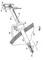
- FIG. 1is a perspective view of a surgical stapler in accordance with the present disclosure shown with the jaws in the open (spaced) position;
- FIG. 2is an enlarged perspective view of the distal end portion of the surgical stapler of FIG. 1 , depicting the jaws in an open (spaced) position;
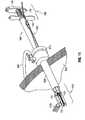
- FIG. 3is an enlarged perspective view of the proximal end portion of the surgical stapler of FIG. 1 corresponding to the jaws in a closed position;
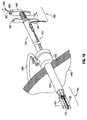
- FIG. 4is an exploded perspective view of the surgical stapler of FIG. 1 with a plunger and a proximal spring separated from an outer tube;
- FIG. 5is an exploded perspective view of the distal end portion of the surgical stapler of FIG. 1 with the movable mounting jaw and stationary mounting jaw separated from the outer tube;
- FIG. 6is a perspective view of the surgical stapler of FIG. 1 being inserted through a surgical port and into a sub-dermal body cavity, the jaws shown in the closed position;
- FIG. 7is a cross-sectional view of the surgical stapler of FIG. 1 taken along section line 7-7 of FIG. 1 ;
- FIG. 8is a cross-sectional view taken along line 8-8 of FIG. 6 ;
- FIG. 9is a perspective view of the surgical stapler of FIG. 1 located within and extending through the surgical port and into a sub-dermal body cavity, showing the jaws in the closed position;
- FIG. 10is a perspective view of the surgical stapler of FIG. 1 inserted through a surgical port to apply purse string sutures to sub-dermal tissue, showing the jaws in the open position;
- FIG. 11is a perspective view of the surgical stapler of FIG. 1 inserted through a surgical port and with a tissue section being inserted between the jaws of the surgical stapler;
- FIG. 12is a perspective view of the surgical stapler of FIG. 1 inserted through a surgical port and the tissue section located between the jaws of the surgical stapler;
- FIG. 13is a perspective view of the surgical stapler of FIG. 1 inserted through a surgical port, wherein the surgical stapler is applying the purse string suture to the tissue section;
- FIG. 14is a cross-sectional view of the surgical stapler taken along section line 14-14 of FIG. 12 ;
- FIG. 15is a cross-sectional view of the surgical stapler taken along section line 15-15 of FIG. 13 ;
- FIG. 16is a perspective view of the surgical stapler of FIG. 1 inserted through a surgical port with the purse string suture attached to the lumen and the suture separated from the surgical stapler;
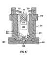
- FIG. 17is a cross-sectional view illustrating formation of a staple of the surgical stapler of FIG. 1 .
- proximalrefers to that part or component closer to the user or operator, i.e., surgeon or physician
- distalrefers to that part or component further away from the user.
- the example embodiments of the present disclosureare provided by virtue of a mechanical resecting, stapling, and/or suturing attachment which is coupleable to and remotely actuable by a mechanical device driver.
- the attachmentincludes a pair of jaws for clamping the selected section of tissue therebetween, the jaws expanding and closing in a substantially parallel disposition.
- the example embodiments of the present disclosureillustrate that in a natural state, the jaws would be in an open configuration. A catch stop would be pulled back to close the jaws in order to allow for insertion of the jaws through an access port such as a trocar. Once inside the patient, the jaws would be returned to an open configuration and would be slid over tissue, where the purse string staples of the stapling assemblies would be placed. Once the surgeon determines an appropriate position, an optional safety would be removed and the surgeon would move the movable jaw toward the fixed jaw. This action causes the staples to form pinching tissue around the outer diameter of the tissue, with a suture captured inside the formed staple. The surgical device would then be withdrawn, leaving the formed staples and the suture attached to the tissue.
- connectmay refer to adhere, affix, anchor, attach, band, bind, bolt, bond, brace, button, cohere, fasten, couple, embed, establish, fix, grip, hold, hook, implant, link, lock, lodge, screw, seal, rivet, tack on, tighten, or unite.
- connectmay refer to linking/fastening/attaching/locking any type of materials or elements or components or units in a removable or detachable or interchangeable manner.
- connect and “lock”may be used interchangeably throughout the present disclosure.
- FIG. 1a perspective view of a surgical stapler in accordance with the present disclosure is presented.
- the surgical stapler 100includes a staple assembly 104 positioned at a distal end portion and a plunger assembly 106 positioned at a proximal end portion of the surgical stapler 100.
- a tubular member 102forming an outer tube, extends between the distal and proximal end portions of the surgical stapler 100.
- the stapling assembly 104includes a jaw assembly.
- the jaw assemblyincludes a first jaw 122 and a second jaw 124.
- the first jaw 122is preferably a stationary mounting jaw mounted to the distal end of the tubular member 102.
- the second jaw 124is preferably a movable mounting jaw.
- the first jaw 122may be of a different length compared to the second jaw 124.
- the second jaw 124may be longer than the first jaw 122 or vice versa such that it extends proximally beyond the other jaw.
- a stapling assembly 126, 128is disposed along each of the mounting jaws 122, 124, the stapling assemblies 126, 128 being configured to apply at least one surgical staple to the tissue such that the distal end of the suture 130, in combination with the at least one surgical staple, forms a purse string with the tissue. This stapling/suturing process will be further described below with reference to FIGS. 6 and 9-13 .
- the stapling assembly 104also includes a pair of suture guides 132, 134.
- a first guide 132is positioned at one end of the first jaw 122 and a second guide 134 is positioned at one end of the second jaw 124.
- the suture guides 132, 134are configured to receive the distal end of the suture 130.
- the suture 130runs from the proximal end to the distal end of the surgical stapler 100, as will be described below.
- the stapling assembly 104also includes a biasing member 136.
- the biasing member 136is for the second jaw 124 to travel linearly in a direction substantially perpendicular to its longitudinal axis, while maintaining the substantially parallel relation between the first and second jaws 122, 124. In other words, the biasing member 136 allows for the second jaw 124 to move substantially parallel to the first jaw 122.
- the tubular member 102includes a suture retaining mechanism 115.
- the retaining mechanism 115is retained adjacent the tubular member 102 through which a first suture section 110 and a second suture section 112 are run.
- the tubular member 102is preferably an elongated tube of deformable plastic, such as 80 Duro polyvinyl chloride.
- the retaining mechanism 115releasably retains the first and second suture sections 110, 112 longitudinally along a length of the tubular member 102.
- Surgical stapler 100further includes a mounting structure for mounting the retaining mechanism 115 to the tubular member 102.
- a holder 114 and a clamp 116hold and clamp the first and second suture sections 110, 112 to the tubular member 102.
- Holder 114is mounted adjacent the tubular member 102 and has an opening through which the suture sections extend.
- Clamp 116is located proximal of holder 114, adjacent the proximal end portion of the surgical stapler 100 and positioned adjacent tubular member 102 through which first and second suture sections 110, 112 are disposed.
- clamp 116allows a user to grasp and engage the clamp 116 during use of the surgical stapler 100, so that the proximal end 118 of the first suture section 110 and the proximal end 120 of the second suture section 112 remain intact during operation.
- One skilled in the artmay contemplate using various combinations and equivalent embodiments of holders and clamps to releasably retain first and second suture sections 110, 112 substantially adjacent the tubular member 102.
- the retaining mechanism 115can be positioned along other portions of the tubular member 102. Additionally, use of more than one retaining mechanism 115 in a plurality of different configurations is contemplated.
- the proximal end portion of the surgical stapler 100includes a plunger assembly 106.
- the plunger assembly 106includes a handle 140, a spring 142, a grip 144, and a recess 146 located on a portion of the grip 144 in order to hold a catch lock 302, as described below with reference to FIG. 3 .
- the distal spring 142is positioned between the handle 140 and the grip 144. Upon release of the catch lock 302, the distal spring 142 moves the handle 140 away from the grip 144. The surgeon may then access and use the grip 144 to actuate the plunger assembly 106.
- the guides 132, 134may be positioned on the distal ends of the first jaw 122 and the second jaw 124, respectively. However, guides 132, 134 may alternatively in additionally be positioned on the proximal ends of the first jaw 122 and the second jaw 124, respectively. Additionally, a plurality of guides 132, 134 may be positioned across the length of the pair of stapling assemblies 126, 128, on the inner surface of the first and second jaws 122, 124.
- the suture guides 132, 134provide for running the proximal end 118 of the first suture section 110 and the proximal end 120 of the second suture section 112 through the retaining mechanism 115 located adjacent the tubular member 102, to the pair of stapling assemblies 126, 128 where the distal end of the suture 130 is located.
- One skilled in the artmay contemplate using various combinations and equivalent embodiments of guides to releasably retain the distal end of the suture 130 substantially adjacent the first and second stapling assemblies 126, 128 of the first and second jaws 122, 124.
- suture 130may be placed into guides 132, 134 and through tubular member 102, with suture 130 strung taut between guides 132, 134 to be disposed substantially adjacent first and second stapling assemblies 126, 128.
- the movable mounting jaw or second jaw 124includes a cam arm 202, the cam arm 202 being positioned to move the jaw 124 substantially perpendicular to the longitudinal axis in response to longitudinal movement of the plunger assembly 106 (see FIG. 1 ).
- the cam arm 202includes a cam slot 204 for receiving a cam pin 206.
- the cam pin 206allows for substantially parallel movement of the second jaw 124 relative to the longitudinal axis of the first jaw 122 and relative to the longitudinal movement of the plunger assembly 106 (see FIG. 1 ).
- a cam block 210( FIG. 7 ) having a cam surface 208 is positioned adjacent the cam arm 202.
- the cam block 210is positioned at the distal end of the plunger assembly 106 and actuates the cam arm 202 to move the second jaw 124 toward the first jaw 122. That is, the distal movement of the plunger assembly 106 causes the cam surface 208 to engage cam arm 202 to cause the substantially parallel closure of the first and second jaws 122, 124 as can be appreciated by comparing FIGS. 7 and 8 . The movement of the cam arm 202 also moves the second jaw 124 to apply a force against the tissue to effect firing of the staples as described below.
- FIG. 3illustrates how the handle 140 and grip 144 of the plunger assembly 106 are actuated.
- a pivotal catch lock 302is securely locked at the recess 146 of the grip 144.
- the catch lock 302is attached to the handle 140 via a catch pin 306.
- the catch lock 302is releasably secured to the grip 144 via a catch stop 304 that frictionally locks into the recess 146 of the grip 144.
- the handle 140may be manipulated by a user to actuate the plunger assembly 106 to drive the cam block 210 (see FIG.
- the catch lock 302enables the holding of the first and second jaws 122, 124 in a closed position for insertion through, for example, a surgical port 610 and surgical port tube 620 (see FIG. 6 ).
- the exploded perspective viewillustrates how certain components of the surgical instrument 100 are connected to each other; however, one skilled in the art may contemplate connecting such components in a plurality of different configurations.
- the handle 140is operably connected to a proximal end of a drive shaft 402 ( FIG. 4 ).
- the distal end of the drive shaft 402includes the cam block 210 having cam surface 208 (see FIG. 2 ).
- the catch lock 302 having a catch stop 304is connected to an upper portion of the handle 140 via the catch pin 306 (see FIG. 3 ).
- the drive shaft 402is slidably positioned within the tubular member 102.
- the drive shaft 402travels through spring 142 in order to allow for a predetermined distance between the handle 140 and the grip 144.
- the remaining componentshave been fully described above with reference to FIGS. 1-3 .
- Cam arm 202interconnects the second jaw 124 to the first jaw 122 via a jaw mount 502.
- the jaw mount 502( FIG. 5 ) creates a connecting relationship between the first jaw 122, the second jaw 124, and the tubular member 102.
- the first jaw 122is connected to the jaw mount 502 via a jaw receiving slot 512.
- the second jaw 124is connected to the jaw mount 502 via pin 508 extending through hole 510 of cam arm 202 ( FIG. 5 ).
- Biasing member 136is inserted into the spring slot 506 of jaw mount 502.
- a jaw mount pin 508is inserted through the perpendicular slots 504 of the jaw mount 502 and then through the pin hole 510 in order to securedly, yet movably affix the cam arm 202 of the second jaw 124 to the jaw mount 502.
- Thisconnects the first and second jaws 122, 124.
- the tubular member 102connects to the cam arm 202 via the cam pin 206 inserted through a cam pin hole 522 of the tubular member 102 and engaging slot 204 of cam arm 202.
- one or more tube suture guides 520may be positioned on various regions of the outer surface of the tubular member 102 in order to provide for supplemental support of the first and second suture sections 110, 112.
- the guideshave a recess dimensioned to frictionally engage the suture.
- the suture guides 520may be positioned across the entire length of tubular member 102.
- FIG. 6depicts the surgical instrument 100 before it is inserted into a body of a patient.
- the stapling assembly 104 of the surgical instrument 100is inserted through the surgical port 610 having a surgical port tube 620.
- the surgical port 610is positioned adjacent tissue 640 of a patient, and extends through the tissue 640 of the patient to provide access to the body cavity of the patient.
- One or more connectors 630may be connected to the surgical port 610.
- the surgical portcan include one or more internal seals.
- the jawsin a natural state, the jaws would be in an open configuration. The jaws would then be closed to allow for insertion of the jaws through a surgical port, e.g. trocar. (Catch lock 302 can be used to hold the jaws in the closed position). Once inside the patient, the jaws would be returned to an open configuration and would be slid over tissue, where the purse string staples of the stapling assemblies would be placed. Once the surgeon determines an appropriate position, plunger would be actuated to move the movable jaw toward the fixed jaw.
- a surgical porte.g. trocar.
- the stapleswould be forced from the jaws, causing the staples to form pinching tissue around the outer diameter of the tissue, with a suture captured inside the formed staple.
- the plungerwould be released, allowing the jaws to move to the open position, thus leaving the formed staples and the suture attached to the tissue.
- the jawswould then be re-closed for removal through the port.
- a two stage operationis therefore contemplated with the first stage closing the jaws to clamp tissue and the second stage applying sufficient force to the tissue to retract elements within the jaws as described below to form the staples.
- a tactile indicator, or a stopcan be provided to demarcate the two stages. If a stop is provided, it would be released after initial jaw approximation to allow additional movement to fire the staples.
- the jawscan be in a closed position in a natural state and then after insertion through a surgical port moved to an open position to be slid over tissue.
- a portion of the surgical instrument 100is inserted through the surgical port 610 and the surgical port tube 620 so as to expose the stapling assembly 104 within the body of the patient.
- the plunger assembly 106remains in a locked configuration due to the locking engagement of the catch stop 304 of catch lock 302 in recess 146 of the grip 144 (see also FIG. 3 ).
- the catch stop 304 of the catch lock 302is manually released by the surgeon from the recess 146 of the grip 144 in order to actuate the plunger assembly 106 via the distal spring 142 (see also FIG. 3 ). That is, when the catch stop 304 is released, the handle 140 of plunger assembly 106 is moved proximally in a longitudinal direction due to the bias of spring 142. This withdraws the cam block 210 from cam arm 202 (see FIG. 2 ) so that the second jaw 124 moves away from the first jaw 122 in a substantially parallel fashion (see also the open jaw position of FIG. 7 ). Thus, an opening is created between the first and second jaws 122, 124 in order to grasp tissue, for example, intestinal tissue 1110 (see FIGS. 11-13 described below).
- the first and second jaws 122, 124are moved to approach a target as shown in FIG. 11 , such as, for example, intestinal tissue 1110. Once the surgeon locates the target tissue 1110, the surgeon may maneuver the first and second jaws 122, 124 to grasp the target tissue 1110.
- the first and second jaws 122, 124then grasp a portion of the intestinal tissue 1110 as shown in FIG. 12 (and FIG. 14 ).
- the intestinal tissue 1110is positioned between the first and second jaws 122, 124 so that the first and second stapling assemblies 126, 128 contact a portion or portions of the tissue 1110.
- the cam arm 202can be partially moved downwardly by initial longitudinal movement of the plunger assembly 106 so as to partially compress the biasing member 136. This is shown by the movement of the cam slot 204 relative to the fixed cam pin 206.
- the cam slot 204may move within a predetermined region defined by the location of the cam pin 206.
- the surgeonsubsequently manipulates the handle 140, e.g. moves the handle 140 longitudinally distally to overcome the bias of spring 142 in order to actuate the plunger assembly 106 to move the cam block 210 to the cam arm 202 (see FIG. 2 ), which in turn moves the second jaw 124 closer to the first jaw 122 in a substantially parallel fashion. That is, as the cam block 210 moves distally, the cam surface 208 rides across the top surface of the cam arm 202 to force/actuate the second jaw 124 to move in substantially parallel movement relative to the first jaw 122. This overrides the distal spring 136 which normally maintains the jaws 122, 124 open relative to each other.
- the intestinal tissue 1110is firmly grasped between the first jaw 122 and the second jaw 124 (see also FIG. 15 ).
- the firm graspallows the first and second stapling assemblies 126, 128 to firmly contact the tissue 1110 in order to fire staples through the tissue 1110 and/or to suture the tissue 1110 in order to form a purse string suture.
- the cam arm 202is fully moved downwardly so as to fully compress the biasing member 136. (One skilled in the art may contemplate using a plurality of different biasing members to interact with the cam arm 202). This is shown by the movement of the cam slot 204 relative to the fixed cam pin 206.
- the cam slot 204may move within a predetermined region defined by the location of the cam pin 206. Therefore, in accordance with FIGS. 14 and 15 , the second jaw 124 is movable relative to the first jaw 122, in a substantially parallel manner, via a cam arm 202 riding in a cam slot 204. Moreover, in FIG. 14 , the distal end of the suture 130 is somewhat taut, whereas in FIG. 15 , the distal end of the suture 130 is loose.
- Staple cartridge 316has a housing 319 having a pair of opposed walls 328, each defining an internal opening 320.
- each wall 328is provided on the outside with a stiffener plate and has a first slot 329 extending longitudinally of the opening 320 in order to slidingly receive one side of a staple 321, that is, a rounded transition portion.
- a second slot 330 of greater width than the slot 329extends coaxially of the slot 329 in order to slidably receive one side of a former 322.
- Former 322is moved by rib 318.
- the width of a staple 321is greater than the width of a pusher 322. Further, the lower surface of each former 322 is provided with a surface complementary to the undulating base 323 of a staple 321 so as to have a projection (not shown) seated in the recess 324 of the staple 321. This arrangement serves to center the staple 321 within the opening 320 while also ensuring uniform motion of a staple 321 out of the opening 320.
- each lip 331is disposed at one end of the staple receiving slot 329 in a wall 328. Further, the lips 331 are spaced apart to define an outlet of less width than the opening 320 and less width than a staple 321.
- the lips 331are pushed rearwardly while former 322 remains stationary applying lateral forces against the legs 325 by the lips 331 so that the legs 325 begin to deform and move towards each other while penetrating into the layer of tissue.
- the biasing force on the former 322is sufficient to push the deformed staple 321 through the outlet of the mouth of the opening 320 past the lips 331 while deforming the lips 331 sufficiently to permit passage.
- the amount of deformation of the lips 331is sufficient to permit passage of the deformed staple 321 while at the same time being insufficient to overly compress the layer of tissue.
- the purse stringis pulled from the retainers and the stapler removed from the body.
- the plunger assembly 106operably cooperates with the cam arm 202, where the cam arm 202 slidably moves within a predetermined space defined by a cam slot 204.
- the cam slot 204moves and the biasing member 136 compresses substantially perpendicular to a longitudinal axis of the stapler.
- the perpendicular slot 504 of the jaw mount 502may be moved in relation to the movement of the cam arm 202.
- the perpendicular slot 504is configured to move within a region defined by a fixed jaw mount pin 508.
- the stapling assembly 104has completed its task by stapling/suturing the target tissue 1110.
- the staplescan be applied in the manner described in U.S. Patent No. 4,821,939 , incorporated by reference herein in its entirety.
- the distal end of the suture 130is suspended from the target tissue 1110.
- the suture 130may be released from the surgical stapler 100 by the clamp 116.
- the clamp 116may be released from the holder 114 in order to allow the surgeon to cut the suture 130.
- one skilled in the artmay contemplate making the first jaw movable and the second jaw fixed, by connecting the cam arm to the first jaw, instead of the second jaw. It is also contemplated that both jaws may each include a cam arm in order to make both jaws movable. In each of these scenarios, the jaws will move in a substantially parallel fashion relative to each other. It is also contemplated that one or both of the jaws can move in a pivoting movement.
- a safety mechanism(not shown) may be provided at the proximal end of handle 140 for preventing undesired clamping of the handle 140.
- Safety mechanismmay be in the form of a lever pivotally mounted about a pivot such as a pin.
- the safety mechanismmay be sized to permit pivoting by a thumb or a free finger of the user.
- the tubular member 102may be a flexible shaft.
- the flexible shaftmay include a tubular sheath formed of an elastomeric material. Various lengths of this shaft may be provided in conjunction with the present disclosure.
- the flexible shaft 102 and the plunger assembly 106may be separable. If separable, the interface between the proximal end of the shaft 102 and the distal end of the handle 140 should include a coupling means for any drive components.
- the flexible drive shaft 102can be capable of translating a torque from one or more motors in the handle 140 to the distal end of the shaft 102, while still being flexible enough to be bent, angled, curved, etc. as the surgeon deems necessary to "snake" through the bowel of a patient.
- One skilled in the artmay contemplate a handle that includes no motors, or any other type of electro-mechanical driving means.
- the handle 140may include a remote status indicator (not shown).
- the remote status indicatormay comprise an LCD (or similar read output device) by which the user may gain knowledge of the position of components (for example whether a clamping element is in the proper position prior to the driving of the staples).
- first and second stapling assemblies 126, 128may each include a plurality of sensors (not shown).
- the first stapling assembly 126may include a first sensor electrode that electrically communicates via communication wires with a first contact pad
- the second stapling assembly 128may include a second sensor that electrically communicates via communication wires with a second contact pad.
- the contact nodesmay electrically communicate with communication wires to form a sensor circuit, such that when the first jaw 122 and the second jaw 124 are clamped together, the sensor electrodes are in contact, the sensor circuit is closed, and the surgeon is alerted via other circuit components (not shown) to the clamped position of the jaws 122, 124.
- Suture materialmay be classified as either absorbable or non-absorbable.
- Absorbable suturemay be placed below the skin surface where in time, the body decomposes, dissolves, and absorbs the suture material.
- non-absorbable suture materialsalso used during surgical procedures. The non-absorbable materials may be employed and manually removed after the intended purpose has been completed such as a surgical site that is considered healed.
Landscapes
- Health & Medical Sciences (AREA)
- Life Sciences & Earth Sciences (AREA)
- Surgery (AREA)
- Heart & Thoracic Surgery (AREA)
- Engineering & Computer Science (AREA)
- Biomedical Technology (AREA)
- Nuclear Medicine, Radiotherapy & Molecular Imaging (AREA)
- Medical Informatics (AREA)
- Molecular Biology (AREA)
- Animal Behavior & Ethology (AREA)
- General Health & Medical Sciences (AREA)
- Public Health (AREA)
- Veterinary Medicine (AREA)
- Rheumatology (AREA)
- Surgical Instruments (AREA)
Abstract
Description
- This application claims priority from provisional application serial no.
61/372,610, filed August 11, 2010 - The present disclosure relates to a surgical stapler, and more particularly, to an endoscopic surgical stapler for affixing a purse string suture to tissue.
- A circular stapler is one device that can be used in surgical applications for the joining of body tissue. In the area of surgical anastomotic stapling, it can be used for joining pieces of tissue in a manner such that a continuous pathway, lumen, or surgical opening, is formed after the tissue is stapled together. This lumen is formed when a circular array of staples is used to join two pieces of tissue after which the tissue interior to the innermost circle of staples is cut out by a concentric circular retractable blade. Retraction of the circular stapler removes the cut tissue to form a lumen.
- In the art of surgery, it has been known to use purse string sutures and purse string appliers for circular staplers. The suture is typically placed using a needle, staples or other suitable means for attaching the suture to the tissue. After attachment, the ends of the suture remain loose for pulling to contract or close the tissue. Conventional needles and instruments are well known in the art for inserting or attaching purse string sutures to tissue. For example, purse string surgical instruments utilizing needles and toothed jaws are disclosed in
U.S. Pat. Nos. 4,345,600 ;4,915,107 ; and5,188,636 .U.S. Pat. Nos. 4,821,939 ;5,158,567 ; and5,490,856 disclose purse string applicators with stapling cartridges for attaching a suture to tissue and are incorporated herein by reference in their entirety. - Surgical instruments for attaching a purse string can require a relatively high degree of dexterity. Typically, for example, at least one free unattached end portion of the suture is in a loose state, both during and after attachment to tissue. This requires the user of the surgical instrument to either hold or keep track of the unattached end portion. Furthermore, when attempting to pull the purse string to a desired tension, it can be difficult to maintain that tension while attempting other hand movements.
- It would therefore be advantageous to provide a purse string instrument having means to hold or retain at least the end portion or portions of the suture during certain surgical procedures.
- Additionally, with the advent of minimally invasive, e.g. endoscopic, surgical procedures, it would be advantageous to provide an endoscopic purse string device which could minimally invasively apply purse string sutures. The benefits of minimally invasive surgery, e.g. shorter recovery time, reduced patient trauma, shorter hospital stay, etc. are well known.
- In one aspect of the present disclosure, an endoscopic surgical stapler is provided which includes an elongated tubular member having a distal end portion and a proximal end portion, a first jaw positioned at the distal end portion of the tubular member and having a longitudinal axis, and a second jaw disposed in substantially parallel relation to the first jaw at the distal end portion of the tubular member. The second jaw is movable toward the first jaw in a direction substantially perpendicular to its longitudinal axis, while maintaining the substantially parallel relation between the first and second jaws. The surgical stapler further includes a stapling assembly disposed in each of the first and second jaws and configured to apply surgical staples to the tissue such that a suture, in combination with the surgical staples, forms a purse string with the tissue when the surgical stapler is activated.
- In some embodiments, the surgical stapler includes a plunger longitudinally movable within the tubular member and a cam arm positioned to move the second jaw substantially perpendicularly to the longitudinal axis in response to longitudinal movement of the plunger.
- The surgical stapler is preferably sized to allow insertion of the surgical stapler into a surgical port for use in a minimally invasive surgical procedure.
- The surgical stapler can include a suture retaining member for mounting a suture onto an outer surface of the tubular member. The surgical stapler can have a plurality of guides having slots positioned on the tubular member for releasably retaining a portion of the suture adjacent the tubular member.
- The first jaw can have a first length and the second jaw can have a second length, wherein the second length is greater than the first length such that the second jaw may extend proximally of the first jaw.
- In some embodiments, the surgical stapler includes a locking mechanism to prevent unintended firing of the surgical staples from the surgical stapler. The locking mechanism may in some embodiments be a removable tab or a pivotable catch. The removable tab can act as a stop to limit longitudinal movement of the plunger in relation to the tubular member. The pivotable catch is preferably sized and shaped to removably couple the catch within a lock recess to limit longitudinal movement of the plunger in relation to the outer tube.
- The surgical stapler can include a proximal spring to bias the plunger in a proximal position relative to the tubular member and a distal spring to bias the second jaw away from the first jaw. The proximal and distal springs can act to prevent unintentional expulsion of the surgical staples from the surgical stapler.
- In another aspect of the present disclosure, an endoscopic surgical stapler is provided for applying a suture to tissue comprising an elongated tubular member having a proximal end portion and a distal end portion, and first and second jaws positioned adjacent the distal end portion of the tubular member. At least the second jaw is movable toward the first jaw from a spaced apart position to an approximated position, and each of the jaws includes a plurality of staples and a portion of a suture. An approximation mechanism moves at least the first jaw with respect to the second jaw, and includes a linear slidable member positioned within the elongated tubular member.
- The biasing member may be disposed adjacent the portion of the second jaw that extends beyond the first jaw. The first jaw may be fixed, whereas the second jaw may be movable relative to the first jaw in a substantially parallel movement toward the first jaw. The first and second jaws can include anvilless stapling assemblies for forming the staples and applying a purse string.
- The accompanying drawings, which are incorporated in and form part of the specification, illustrate the present disclosure when viewed with reference to the description, wherein:
FIG. 1 is a perspective view of a surgical stapler in accordance with the present disclosure shown with the jaws in the open (spaced) position;FIG. 2 is an enlarged perspective view of the distal end portion of the surgical stapler ofFIG. 1 , depicting the jaws in an open (spaced) position;FIG. 3 is an enlarged perspective view of the proximal end portion of the surgical stapler ofFIG. 1 corresponding to the jaws in a closed position;FIG. 4 is an exploded perspective view of the surgical stapler ofFIG. 1 with a plunger and a proximal spring separated from an outer tube;FIG. 5 is an exploded perspective view of the distal end portion of the surgical stapler ofFIG. 1 with the movable mounting jaw and stationary mounting jaw separated from the outer tube;FIG. 6 is a perspective view of the surgical stapler ofFIG. 1 being inserted through a surgical port and into a sub-dermal body cavity, the jaws shown in the closed position;FIG. 7 is a cross-sectional view of the surgical stapler ofFIG. 1 taken along section line 7-7 ofFIG. 1 ;FIG. 8 is a cross-sectional view taken along line 8-8 ofFIG. 6 ;FIG. 9 is a perspective view of the surgical stapler ofFIG. 1 located within and extending through the surgical port and into a sub-dermal body cavity, showing the jaws in the closed position;FIG. 10 is a perspective view of the surgical stapler ofFIG. 1 inserted through a surgical port to apply purse string sutures to sub-dermal tissue, showing the jaws in the open position;FIG. 11 is a perspective view of the surgical stapler ofFIG. 1 inserted through a surgical port and with a tissue section being inserted between the jaws of the surgical stapler;FIG. 12 is a perspective view of the surgical stapler ofFIG. 1 inserted through a surgical port and the tissue section located between the jaws of the surgical stapler;FIG. 13 is a perspective view of the surgical stapler ofFIG. 1 inserted through a surgical port, wherein the surgical stapler is applying the purse string suture to the tissue section;FIG. 14 is a cross-sectional view of the surgical stapler taken along section line 14-14 ofFIG. 12 ;FIG. 15 is a cross-sectional view of the surgical stapler taken along section line 15-15 ofFIG. 13 ;FIG. 16 is a perspective view of the surgical stapler ofFIG. 1 inserted through a surgical port with the purse string suture attached to the lumen and the suture separated from the surgical stapler; andFIG. 17 is a cross-sectional view illustrating formation of a staple of the surgical stapler ofFIG. 1 .- Other features of the present disclosure will become apparent from the following detailed description, taken in conjunction with the accompanying drawings, which illustrate, by way of example, the principles of the present disclosure.
- Embodiments of the presently disclosed surgical stapler will now be described in detail with reference to the drawings wherein like numerals designate identical or corresponding elements in each of the several views. As is common in the art, the term "proximal" refers to that part or component closer to the user or operator, i.e., surgeon or physician, while the term "distal" refers to that part or component further away from the user. In the following description, well-known functions or constructions are not described in detail to avoid obscuring the present disclosure in unnecessary detail.
- The example embodiments of the present disclosure are provided by virtue of a mechanical resecting, stapling, and/or suturing attachment which is coupleable to and remotely actuable by a mechanical device driver. In particular, the attachment includes a pair of jaws for clamping the selected section of tissue therebetween, the jaws expanding and closing in a substantially parallel disposition.
- The example embodiments of the present disclosure illustrate that in a natural state, the jaws would be in an open configuration. A catch stop would be pulled back to close the jaws in order to allow for insertion of the jaws through an access port such as a trocar. Once inside the patient, the jaws would be returned to an open configuration and would be slid over tissue, where the purse string staples of the stapling assemblies would be placed. Once the surgeon determines an appropriate position, an optional safety would be removed and the surgeon would move the movable jaw toward the fixed jaw. This action causes the staples to form pinching tissue around the outer diameter of the tissue, with a suture captured inside the formed staple. The surgical device would then be withdrawn, leaving the formed staples and the suture attached to the tissue.
- Prior to describing the present disclosure in further detail, it will first be helpful to define various terms that will be used throughout the following discussion. For example:
- The term "connect" or "connecting" may refer to adhere, affix, anchor, attach, band, bind, bolt, bond, brace, button, cohere, fasten, couple, embed, establish, fix, grip, hold, hook, implant, link, lock, lodge, screw, seal, rivet, tack on, tighten, or unite. The terms "connect" or "connecting" may refer to linking/fastening/attaching/locking any type of materials or elements or components or units in a removable or detachable or interchangeable manner. The terms "connect" and "lock" may be used interchangeably throughout the present disclosure.
- Reference will now be made in detail to embodiments of the present disclosure. While certain embodiments of the present disclosure will be described, it will be understood that it is not intended to limit the embodiments of the present disclosure to those described embodiments. To the contrary, reference to embodiments of the present disclosure is intended to cover alternatives, modifications, and equivalents as may be included within the spirit and scope of the embodiments of the present disclosure as defined by the appended claims.
- Referring now in specific detail to the drawings, with like reference numerals identifying similar or identical elements, the present disclosure is shown in cooperation with a surgical stapler for applying a suture to a tissue.
- With reference to
FIG. 1 , a perspective view of a surgical stapler in accordance with the present disclosure is presented. - The
surgical stapler 100 includes astaple assembly 104 positioned at a distal end portion and aplunger assembly 106 positioned at a proximal end portion of thesurgical stapler 100. Atubular member 102, forming an outer tube, extends between the distal and proximal end portions of thesurgical stapler 100. - In particular, the stapling
assembly 104 includes a jaw assembly. The jaw assembly includes afirst jaw 122 and asecond jaw 124. Thefirst jaw 122 is preferably a stationary mounting jaw mounted to the distal end of thetubular member 102. Thesecond jaw 124 is preferably a movable mounting jaw. In an alternative embodiment, thefirst jaw 122 may be of a different length compared to thesecond jaw 124. For example, in one embodiment, thesecond jaw 124 may be longer than thefirst jaw 122 or vice versa such that it extends proximally beyond the other jaw. - A stapling
assembly jaws assemblies suture 130, in combination with the at least one surgical staple, forms a purse string with the tissue. This stapling/suturing process will be further described below with reference toFIGS. 6 and9-13 . - The stapling
assembly 104 also includes a pair of suture guides 132, 134. Afirst guide 132 is positioned at one end of thefirst jaw 122 and asecond guide 134 is positioned at one end of thesecond jaw 124. The suture guides 132, 134 are configured to receive the distal end of thesuture 130. Thesuture 130 runs from the proximal end to the distal end of thesurgical stapler 100, as will be described below. - The stapling
assembly 104 also includes a biasingmember 136. The biasingmember 136 is for thesecond jaw 124 to travel linearly in a direction substantially perpendicular to its longitudinal axis, while maintaining the substantially parallel relation between the first andsecond jaws member 136 allows for thesecond jaw 124 to move substantially parallel to thefirst jaw 122. - The
tubular member 102 includes asuture retaining mechanism 115. Theretaining mechanism 115 is retained adjacent thetubular member 102 through which afirst suture section 110 and asecond suture section 112 are run. Thetubular member 102 is preferably an elongated tube of deformable plastic, such as 80 Duro polyvinyl chloride. Theretaining mechanism 115 releasably retains the first andsecond suture sections tubular member 102. Surgical stapler 100 further includes a mounting structure for mounting theretaining mechanism 115 to thetubular member 102. For example, aholder 114 and aclamp 116 hold and clamp the first andsecond suture sections tubular member 102.Holder 114 is mounted adjacent thetubular member 102 and has an opening through which the suture sections extend.Clamp 116 is located proximal ofholder 114, adjacent the proximal end portion of thesurgical stapler 100 and positioned adjacenttubular member 102 through which first andsecond suture sections clamp 116 allows a user to grasp and engage theclamp 116 during use of thesurgical stapler 100, so that theproximal end 118 of thefirst suture section 110 and theproximal end 120 of thesecond suture section 112 remain intact during operation. One skilled in the art may contemplate using various combinations and equivalent embodiments of holders and clamps to releasably retain first andsecond suture sections tubular member 102. Theretaining mechanism 115 can be positioned along other portions of thetubular member 102. Additionally, use of more than oneretaining mechanism 115 in a plurality of different configurations is contemplated.- The proximal end portion of the
surgical stapler 100 includes aplunger assembly 106. Theplunger assembly 106 includes ahandle 140, aspring 142, agrip 144, and arecess 146 located on a portion of thegrip 144 in order to hold acatch lock 302, as described below with reference toFIG. 3 . Thedistal spring 142 is positioned between thehandle 140 and thegrip 144. Upon release of thecatch lock 302, thedistal spring 142 moves thehandle 140 away from thegrip 144. The surgeon may then access and use thegrip 144 to actuate theplunger assembly 106. - The
guides first jaw 122 and thesecond jaw 124, respectively. However, guides 132, 134 may alternatively in additionally be positioned on the proximal ends of thefirst jaw 122 and thesecond jaw 124, respectively. Additionally, a plurality ofguides assemblies second jaws - The suture guides 132, 134 provide for running the
proximal end 118 of thefirst suture section 110 and theproximal end 120 of thesecond suture section 112 through theretaining mechanism 115 located adjacent thetubular member 102, to the pair of staplingassemblies suture 130 is located. One skilled in the art may contemplate using various combinations and equivalent embodiments of guides to releasably retain the distal end of thesuture 130 substantially adjacent the first andsecond stapling assemblies second jaws - Moreover, during manufacture of the
surgical stapler 100,suture 130 may be placed intoguides tubular member 102, withsuture 130 strung taut betweenguides second stapling assemblies - The movable mounting jaw or
second jaw 124 includes acam arm 202, thecam arm 202 being positioned to move thejaw 124 substantially perpendicular to the longitudinal axis in response to longitudinal movement of the plunger assembly 106 (seeFIG. 1 ). Thecam arm 202 includes acam slot 204 for receiving acam pin 206. Thecam pin 206 allows for substantially parallel movement of thesecond jaw 124 relative to the longitudinal axis of thefirst jaw 122 and relative to the longitudinal movement of the plunger assembly 106 (seeFIG. 1 ). Additionally, a cam block 210 (FIG. 7 ) having acam surface 208 is positioned adjacent thecam arm 202. Thecam block 210 is positioned at the distal end of theplunger assembly 106 and actuates thecam arm 202 to move thesecond jaw 124 toward thefirst jaw 122. That is, the distal movement of theplunger assembly 106 causes thecam surface 208 to engagecam arm 202 to cause the substantially parallel closure of the first andsecond jaws FIGS. 7 and 8 . The movement of thecam arm 202 also moves thesecond jaw 124 to apply a force against the tissue to effect firing of the staples as described below. Figure 3 illustrates how thehandle 140 andgrip 144 of theplunger assembly 106 are actuated. Apivotal catch lock 302 is securely locked at therecess 146 of thegrip 144. Thecatch lock 302 is attached to thehandle 140 via acatch pin 306. Thecatch lock 302 is releasably secured to thegrip 144 via acatch stop 304 that frictionally locks into therecess 146 of thegrip 144. In operation, when the catch stop 304 is released from therecess 146 of thegrip 144, i.e. pivoted out ofrecess 146, thehandle 140 may be manipulated by a user to actuate theplunger assembly 106 to drive the cam block 210 (seeFIG. 2 ) to engagecam arm 202, in order to move thesecond jaw 124 in substantially parallel movement toward thefirst jaw 122. It is noted that when the catch stop 304 is positioned within therecess 146, thedistal spring 142 is in a compressed position. Thus, thedistal spring 142 urges thehandle 140 and thegrip 144 apart when the catch stop 304 is released, thereby opening the first andsecond jaws second jaw 124 returns to its normal position. Thecatch lock 302 enables the holding of the first andsecond jaws surgical port 610 and surgical port tube 620 (seeFIG. 6 ).- The exploded perspective view illustrates how certain components of the
surgical instrument 100 are connected to each other; however, one skilled in the art may contemplate connecting such components in a plurality of different configurations. Thehandle 140 is operably connected to a proximal end of a drive shaft 402 (FIG. 4 ). The distal end of thedrive shaft 402 includes thecam block 210 having cam surface 208 (seeFIG. 2 ). Additionally, thecatch lock 302 having acatch stop 304 is connected to an upper portion of thehandle 140 via the catch pin 306 (seeFIG. 3 ). Thedrive shaft 402 is slidably positioned within thetubular member 102. Thedrive shaft 402 travels throughspring 142 in order to allow for a predetermined distance between thehandle 140 and thegrip 144. The remaining components have been fully described above with reference toFIGS. 1-3 . - Cam arm 202 (see
FIG. 2 ) interconnects thesecond jaw 124 to thefirst jaw 122 via ajaw mount 502. The jaw mount 502 (FIG. 5 ) creates a connecting relationship between thefirst jaw 122, thesecond jaw 124, and thetubular member 102. Thefirst jaw 122 is connected to thejaw mount 502 via ajaw receiving slot 512. Thesecond jaw 124 is connected to thejaw mount 502 viapin 508 extending throughhole 510 of cam arm 202 (FIG. 5 ).Biasing member 136 is inserted into thespring slot 506 ofjaw mount 502. That is, ajaw mount pin 508 is inserted through theperpendicular slots 504 of thejaw mount 502 and then through thepin hole 510 in order to securedly, yet movably affix thecam arm 202 of thesecond jaw 124 to thejaw mount 502. This connects the first andsecond jaws tubular member 102 connects to thecam arm 202 via thecam pin 206 inserted through acam pin hole 522 of thetubular member 102 and engagingslot 204 ofcam arm 202. - In an example embodiment, one or more tube suture guides 520 (
FIG. 5 ) may be positioned on various regions of the outer surface of thetubular member 102 in order to provide for supplemental support of the first andsecond suture sections tubular member 102. - The view of
FIG. 6 depicts thesurgical instrument 100 before it is inserted into a body of a patient. The staplingassembly 104 of thesurgical instrument 100 is inserted through thesurgical port 610 having asurgical port tube 620. Thesurgical port 610 is positionedadjacent tissue 640 of a patient, and extends through thetissue 640 of the patient to provide access to the body cavity of the patient. One ormore connectors 630 may be connected to thesurgical port 610. For certain applications, the surgical port can include one or more internal seals. - The operation of the
surgical stapler 100 will be described with reference toFIGS. 6 and9-13 . In the illustrated embodiment, in summary, in a natural state, the jaws would be in an open configuration. The jaws would then be closed to allow for insertion of the jaws through a surgical port, e.g. trocar. (Catch lock 302 can be used to hold the jaws in the closed position). Once inside the patient, the jaws would be returned to an open configuration and would be slid over tissue, where the purse string staples of the stapling assemblies would be placed. Once the surgeon determines an appropriate position, plunger would be actuated to move the movable jaw toward the fixed jaw. On continued movement, the staples would be forced from the jaws, causing the staples to form pinching tissue around the outer diameter of the tissue, with a suture captured inside the formed staple. Afterward, the plunger would be released, allowing the jaws to move to the open position, thus leaving the formed staples and the suture attached to the tissue. The jaws would then be re-closed for removal through the port. A two stage operation is therefore contemplated with the first stage closing the jaws to clamp tissue and the second stage applying sufficient force to the tissue to retract elements within the jaws as described below to form the staples. Note a tactile indicator, or a stop, can be provided to demarcate the two stages. If a stop is provided, it would be released after initial jaw approximation to allow additional movement to fire the staples. - It is also contemplated that alternatively the jaws can be in a closed position in a natural state and then after insertion through a surgical port moved to an open position to be slid over tissue.
- In use, and with initial reference to
FIG. 9 , in a first position, a portion of thesurgical instrument 100 is inserted through thesurgical port 610 and thesurgical port tube 620 so as to expose the staplingassembly 104 within the body of the patient. In the first position ofFIG. 9 , theplunger assembly 106 remains in a locked configuration due to the locking engagement of the catch stop 304 ofcatch lock 302 inrecess 146 of the grip 144 (see alsoFIG. 3 ). - Next, as shown in
FIG. 10 , in a second position, the catch stop 304 of thecatch lock 302 is manually released by the surgeon from therecess 146 of thegrip 144 in order to actuate theplunger assembly 106 via the distal spring 142 (see alsoFIG. 3 ). That is, when the catch stop 304 is released, thehandle 140 ofplunger assembly 106 is moved proximally in a longitudinal direction due to the bias ofspring 142. This withdraws the cam block 210 from cam arm 202 (seeFIG. 2 ) so that thesecond jaw 124 moves away from thefirst jaw 122 in a substantially parallel fashion (see also the open jaw position ofFIG. 7 ). Thus, an opening is created between the first andsecond jaws FIGS. 11-13 described below). - The first and
second jaws FIG. 11 , such as, for example,intestinal tissue 1110. Once the surgeon locates thetarget tissue 1110, the surgeon may maneuver the first andsecond jaws target tissue 1110. - The first and
second jaws intestinal tissue 1110 as shown inFIG. 12 (andFIG. 14 ). Theintestinal tissue 1110 is positioned between the first andsecond jaws second stapling assemblies tissue 1110. Thecam arm 202 can be partially moved downwardly by initial longitudinal movement of theplunger assembly 106 so as to partially compress the biasingmember 136. This is shown by the movement of thecam slot 204 relative to the fixedcam pin 206. Thecam slot 204 may move within a predetermined region defined by the location of thecam pin 206. - The surgeon subsequently manipulates the
handle 140, e.g. moves thehandle 140 longitudinally distally to overcome the bias ofspring 142 in order to actuate theplunger assembly 106 to move thecam block 210 to the cam arm 202 (seeFIG. 2 ), which in turn moves thesecond jaw 124 closer to thefirst jaw 122 in a substantially parallel fashion. That is, as thecam block 210 moves distally, thecam surface 208 rides across the top surface of thecam arm 202 to force/actuate thesecond jaw 124 to move in substantially parallel movement relative to thefirst jaw 122. This overrides thedistal spring 136 which normally maintains thejaws second jaw 124 closer to thefirst jaw 122 in a substantially parallel fashion, theintestinal tissue 1110 is firmly grasped between thefirst jaw 122 and the second jaw 124 (see alsoFIG. 15 ). The firm grasp allows the first andsecond stapling assemblies tissue 1110 in order to fire staples through thetissue 1110 and/or to suture thetissue 1110 in order to form a purse string suture. Note that thecam arm 202 is fully moved downwardly so as to fully compress the biasingmember 136. (One skilled in the art may contemplate using a plurality of different biasing members to interact with the cam arm 202). This is shown by the movement of thecam slot 204 relative to the fixedcam pin 206. Thecam slot 204 may move within a predetermined region defined by the location of thecam pin 206. Therefore, in accordance withFIGS. 14 and 15 , thesecond jaw 124 is movable relative to thefirst jaw 122, in a substantially parallel manner, via acam arm 202 riding in acam slot 204. Moreover, inFIG. 14 , the distal end of thesuture 130 is somewhat taut, whereas inFIG. 15 , the distal end of thesuture 130 is loose. - The staples are formed by anvilless stapling assemblies as shown in
FIGS. 17 .Staple cartridge 316 has ahousing 319 having a pair of opposedwalls 328, each defining aninternal opening 320. In addition, eachwall 328 is provided on the outside with a stiffener plate and has afirst slot 329 extending longitudinally of theopening 320 in order to slidingly receive one side of astaple 321, that is, a rounded transition portion. In addition asecond slot 330 of greater width than theslot 329 extends coaxially of theslot 329 in order to slidably receive one side of a former 322. Former 322 is moved byrib 318. - The width of a
staple 321 is greater than the width of apusher 322. Further, the lower surface of each former 322 is provided with a surface complementary to the undulatingbase 323 of a staple 321 so as to have a projection (not shown) seated in therecess 324 of thestaple 321. This arrangement serves to center thestaple 321 within theopening 320 while also ensuring uniform motion of a staple 321 out of theopening 320. - The
legs 325 ofstaple 321 are deformed at the mouth of eachopening 320 by a pair of inwardly directedlips 331. As indicated, eachlip 331 is disposed at one end of thestaple receiving slot 329 in awall 328. Further, thelips 331 are spaced apart to define an outlet of less width than theopening 320 and less width than astaple 321. - Thus, as jaws apply pressure to tissue, the
lips 331 are pushed rearwardly while former 322 remains stationary applying lateral forces against thelegs 325 by thelips 331 so that thelegs 325 begin to deform and move towards each other while penetrating into the layer of tissue. - As the staple is formed, the biasing force on the former 322 is sufficient to push the
deformed staple 321 through the outlet of the mouth of theopening 320 past thelips 331 while deforming thelips 331 sufficiently to permit passage. The amount of deformation of thelips 331 is sufficient to permit passage of thedeformed staple 321 while at the same time being insufficient to overly compress the layer of tissue. - Once the stapler has been fired, the purse string is pulled from the retainers and the stapler removed from the body.
- In summary, with reference to
FIGS. 6 and9-13 theplunger assembly 106 operably cooperates with thecam arm 202, where thecam arm 202 slidably moves within a predetermined space defined by acam slot 204. Thecam slot 204 moves and the biasingmember 136 compresses substantially perpendicular to a longitudinal axis of the stapler. Furthermore, theperpendicular slot 504 of thejaw mount 502 may be moved in relation to the movement of thecam arm 202. Theperpendicular slot 504 is configured to move within a region defined by a fixedjaw mount pin 508. - In
FIG. 16 , the staplingassembly 104 has completed its task by stapling/suturing thetarget tissue 1110. The staples can be applied in the manner described inU.S. Patent No. 4,821,939 , incorporated by reference herein in its entirety. The distal end of thesuture 130 is suspended from thetarget tissue 1110. Thesuture 130 may be released from thesurgical stapler 100 by theclamp 116. Theclamp 116 may be released from theholder 114 in order to allow the surgeon to cut thesuture 130. - In an alternative embodiment, one skilled in the art may contemplate making the first jaw movable and the second jaw fixed, by connecting the cam arm to the first jaw, instead of the second jaw. It is also contemplated that both jaws may each include a cam arm in order to make both jaws movable. In each of these scenarios, the jaws will move in a substantially parallel fashion relative to each other. It is also contemplated that one or both of the jaws can move in a pivoting movement.
- In an alternative embodiment, a safety mechanism (not shown) may be provided at the proximal end of
handle 140 for preventing undesired clamping of thehandle 140. Safety mechanism may be in the form of a lever pivotally mounted about a pivot such as a pin. The safety mechanism may be sized to permit pivoting by a thumb or a free finger of the user. - In an alternative embodiment, the
tubular member 102 may be a flexible shaft. The flexible shaft may include a tubular sheath formed of an elastomeric material. Various lengths of this shaft may be provided in conjunction with the present disclosure. Moreover, theflexible shaft 102 and theplunger assembly 106 may be separable. If separable, the interface between the proximal end of theshaft 102 and the distal end of thehandle 140 should include a coupling means for any drive components. In alternate embodiments, theflexible drive shaft 102 can be capable of translating a torque from one or more motors in thehandle 140 to the distal end of theshaft 102, while still being flexible enough to be bent, angled, curved, etc. as the surgeon deems necessary to "snake" through the bowel of a patient. One skilled in the art may contemplate a handle that includes no motors, or any other type of electro-mechanical driving means. - In an alternative embodiment, the
handle 140 may include a remote status indicator (not shown). The remote status indicator may comprise an LCD (or similar read output device) by which the user may gain knowledge of the position of components (for example whether a clamping element is in the proper position prior to the driving of the staples). - In an alternative embodiment, the first and
second stapling assemblies first stapling assembly 126 may include a first sensor electrode that electrically communicates via communication wires with a first contact pad, and thesecond stapling assembly 128 may include a second sensor that electrically communicates via communication wires with a second contact pad. The contact nodes may electrically communicate with communication wires to form a sensor circuit, such that when thefirst jaw 122 and thesecond jaw 124 are clamped together, the sensor electrodes are in contact, the sensor circuit is closed, and the surgeon is alerted via other circuit components (not shown) to the clamped position of thejaws - Suture material may be classified as either absorbable or non-absorbable. Absorbable suture may be placed below the skin surface where in time, the body decomposes, dissolves, and absorbs the suture material. There are numerous non-absorbable suture materials also used during surgical procedures. The non-absorbable materials may be employed and manually removed after the intended purpose has been completed such as a surgical site that is considered healed.
- While the present disclosure has been particularly shown and described with reference to the preferred embodiments, it will be understood by those skilled in the art that various modifications inform and detail may be made therein without departing from the scope and spirit of the present disclosure. Accordingly, modifications such as those suggested above, but not limited thereto, are considered the scope of the present disclosure.
- The invention may be described by reference to the following numbered paragraphs:-
- 1. An endoscopic surgical stapler for applying a suture to tissue, the surgical stapler comprising:
- an elongated tubular member having a distal end portion and a proximal end portion;
- a first jaw positioned at the distal end portion of the tubular member and having a longitudinal axis;
- a second jaw disposed in substantially parallel relation to the first jaw at the distal end portion of the tubular member;
- the second jaw movable toward the first jaw in a direction substantially perpendicular to its longitudinal axis, while maintaining the substantially parallel relation between the first and second jaws; and
- a stapling assembly disposed in each of the first and second jaws and configured to apply surgical staples to the tissue such that a suture, in combination with the surgical staples, forms a purse string with the tissue when the surgical stapler is activated.
- 2. The surgical stapler as set forth in
paragraph 1, wherein the first jaw has a first length and the second jaw has a second length, where the second length is greater than the first length. - 3. The surgical stapler as set forth in paragraph 2, further comprising a biasing member disposed adjacent the portion of the second jaw that extends beyond the first jaw.
- 4. The surgical stapler as set forth in
paragraph 1, wherein the first jaw is fixed. - 5. The surgical stapler as set forth in paragraph 3, further comprising a plunger for activating a cam arm associated with the second jaw.
- 6. The surgical stapler as set forth in
paragraph 1, further comprising a suture retaining member for mounting a suture on an outer surface of the surgical instrument. - 7. The surgical stapler as set forth in
paragraph 1, further comprising a locking mechanism for preventing unintended firing of surgical staples from the surgical stapler. - 8. The surgical stapler as set forth in
paragraph 1, further comprising a plurality of guides for releasably retaining a portion of suture. - 9. The surgical stapler as set forth in
paragraph 1, wherein the stapling assemblies are anvilless stapling assemblies. - 10. The surgical stapler as set forth in
paragraph 1, further comprising:- a plunger longitudinally movable in relation to the tubular member; and
- a cam arm positioned to move the second jaw in response to movement of the plunger.
- 11. The surgical stapler as set forth in paragraph 10, further comprising a plurality of guides having slots positioned on an outer surface of the tubular member to retain the suture.
- 12. The surgical stapler as set forth in paragraph 7, wherein the locking mechanism is a removable tab that acts to limit longitudinal movement of the plunger in relation to the outer tube.
- 13. The surgical stapler as set forth in paragraph 7, wherein the locking mechanism is a pivotable catch that is sized and shaped to removably couple with a lock recess to limit longitudinal movement of the plunger in relation to the tubular member.
- 14. The surgical stapler as set forth in paragraph 10, further comprising a spring to bias the plunger in a proximal position relative to the tubular member.
- 15. The surgical stapler as set forth in
paragraph 1, further comprising a spring to bias the second jaw away from the first jaw. - 16. An endoscopic surgical stapler for applying a suture to tissue comprising:
- an elongated tubular member having a proximal end portion and a distal end portion:
- first and second jaws positioned adjacent the distal end portion of the tubular member, at least the second jaw movable toward the first jaw from a spaced apart position to an approximated position, each of the jaws including a plurality of staples and a portion of a suture; and
- an approximation mechanism to move at least the second jaw with respect to the first jaw, the approximation mechanism including a linear slidable member positioned within the elongated tubular member.
- an elongated tubular member having a proximal end portion and a distal end portion:
- 17. The surgical stapler as set forth in
paragraph 16, further comprising a suture retaining member for mounting the suture on the tubular member. - 18. The surgical stapler as set forth in
paragraph 16, wherein the first and second jaws includes anvilless stapling assemblies for forming the staples and applying a purse string with the tissue. - 19. The surgical stapler as set forth in
paragraph 16, wherein the second jaw moves in substantially parallel movement toward the first jaw. - 20. The surgical stapler as set forth in
paragraph 16, further comprising a cam arm associated with the second jaw.
Claims (14)
- An endoscopic surgical stapler for applying a suture to tissue, the surgical stapler comprising:an elongated tubular member having a distal end portion and a proximal end portion;a first jaw positioned at the distal end portion of the tubular member and having a longitudinal axis;a second jaw disposed in substantially parallel relation to the first jaw at the distal end portion of the tubular member;the second jaw movable toward the first jaw in a direction substantially perpendicular to its longitudinal axis, while maintaining the substantially parallel relation between the first and second jaws; anda stapling assembly disposed in each of the first and second jaws and configured to apply surgical staples to the tissue such that a suture, in combination with the surgical staples, forms a purse string with the tissue when the surgical stapler is activated.
- The surgical stapler as set forth in claim 1, wherein the first jaw has a first length and the second jaw has a second length, where the second length is greater than the first length.
- The surgical stapler as set forth in claims 1 or 2, further comprising a biasing member disposed adjacent the portion of the second jaw that extends beyond the first jaw and wherein the first jaw is fixed.
- The surgical stapler as set forth in claims 1, 2 or 3, further comprising:a plunger longitudinally movable in relation to the tubular member; anda cam arm positioned to move the second jaw in response to movement of the plunger.
- The surgical stapler as set forth in any of claims 1-4, further comprising a suture retaining member for mounting a suture on an outer surface of the surgical instrument.
- The surgical stapler as set forth in any of claims 1-5, further comprising a locking mechanism for preventing unintended firing of surgical staples from the surgical stapler.
- The surgical stapler as set forth in any of claims 1-6, further comprising a plurality of guides for releasably retaining a portion of suture.
- The surgical stapler as set forth in any of claims 1-7, wherein the stapling assemblies are anvilless stapling assemblies.
- The surgical stapler as set forth in claim 6, wherein the locking mechanism is a removable tab that acts to limit longitudinal movement of the plunger in relation to the outer tube or a pivotable catch that is sized and shaped to removably couple with a lock recess to limit longitudinal movement of the plunger in relation to the tubular member.
- The surgical stapler as set forth in claim 4, further comprising a spring to bias the plunger in a proximal position relative to the tubular member.
- An endoscopic surgical stapler for applying a suture to tissue comprising:an elongated tubular member having a proximal end portion and a distal end portion:first and second jaws positioned adjacent the distal end portion of the tubular member, at least the second jaw movable toward the first jaw from a spaced apart position to an approximated position, each of the jaws including a plurality of staples and a portion of a suture; andan approximation mechanism to move at least the second jaw with respect to the first jaw, the approximation mechanism including a linear slidable member positioned within the elongated tubular member.
- The surgical stapler as set forth in claim 11, further comprising a suture retaining member for mounting the suture on the tubular member.
- The surgical stapler as set forth in claims 11 or 12, wherein the first and second jaws include anvilless stapling assemblies for forming the staples and applying a purse string with the tissue.
- The surgical stapler as set forth in claims 11, 12 or 13, wherein the second jaw moves in substantially parallel movement toward the first jaw.
Priority Applications (1)
| Application Number | Priority Date | Filing Date | Title |
|---|---|---|---|
| EP17168950.8AEP3225174A1 (en) | 2010-08-11 | 2011-08-10 | Endoscopic purse string surgical device |
Applications Claiming Priority (2)
| Application Number | Priority Date | Filing Date | Title |
|---|---|---|---|
| US37261010P | 2010-08-11 | 2010-08-11 | |
| US13/166,039US8827136B2 (en) | 2010-08-11 | 2011-06-22 | Endoscopic purse string surgical device |
Related Child Applications (1)
| Application Number | Title | Priority Date | Filing Date |
|---|---|---|---|
| EP17168950.8ADivisionEP3225174A1 (en) | 2010-08-11 | 2011-08-10 | Endoscopic purse string surgical device |
Publications (3)
| Publication Number | Publication Date |
|---|---|
| EP2417916A2true EP2417916A2 (en) | 2012-02-15 |
| EP2417916A3 EP2417916A3 (en) | 2014-05-21 |
| EP2417916B1 EP2417916B1 (en) | 2017-05-24 |
Family
ID=44677772
Family Applications (2)
| Application Number | Title | Priority Date | Filing Date |
|---|---|---|---|
| EP17168950.8AWithdrawnEP3225174A1 (en) | 2010-08-11 | 2011-08-10 | Endoscopic purse string surgical device |
| EP11250716.5ANot-in-forceEP2417916B1 (en) | 2010-08-11 | 2011-08-10 | Endoscopic purse string surgical device |
Family Applications Before (1)
| Application Number | Title | Priority Date | Filing Date |
|---|---|---|---|
| EP17168950.8AWithdrawnEP3225174A1 (en) | 2010-08-11 | 2011-08-10 | Endoscopic purse string surgical device |
Country Status (6)
| Country | Link |
|---|---|
| US (3) | US8827136B2 (en) |
| EP (2) | EP3225174A1 (en) |
| JP (3) | JP6141572B2 (en) |
| AU (1) | AU2011203361A1 (en) |
| CA (1) | CA2746300A1 (en) |
| ES (1) | ES2629215T3 (en) |
Cited By (8)
| Publication number | Priority date | Publication date | Assignee | Title |
|---|---|---|---|---|
| CN103860218A (en)* | 2012-12-12 | 2014-06-18 | 苏州天臣国际医疗科技有限公司 | Pouch sewing device |
| CN104434241A (en)* | 2013-09-23 | 2015-03-25 | 瑞奇外科器械(中国)有限公司 | End effector, surgical operating instrument and purse-string forceps |
| US9375218B2 (en) | 2006-05-03 | 2016-06-28 | Datascope Corp. | Systems and methods of tissue closure |
| CN104434242B (en)* | 2013-09-23 | 2017-06-16 | 瑞奇外科器械(中国)有限公司 | End effector, surgical operating instrument and purse-string forceps |
| US10485545B2 (en) | 2013-11-19 | 2019-11-26 | Datascope Corp. | Fastener applicator with interlock |
| CN113194852A (en)* | 2018-10-19 | 2021-07-30 | 耐氏体内吻合术医疗器械公司 | Apparatus and method for minimally invasive surgical treatment |
| EP3868307A1 (en)* | 2020-02-19 | 2021-08-25 | Covidien LP | Laparoscopic purse string suture device |
| US11653928B2 (en) | 2018-03-28 | 2023-05-23 | Datascope Corp. | Device for atrial appendage exclusion |
Families Citing this family (95)
| Publication number | Priority date | Publication date | Assignee | Title |
|---|---|---|---|---|
| US20050177176A1 (en)* | 2004-02-05 | 2005-08-11 | Craig Gerbi | Single-fold system for tissue approximation and fixation |
| US8490851B2 (en)* | 2008-01-15 | 2013-07-23 | Covidien Lp | Surgical stapling apparatus |
| US8827136B2 (en) | 2010-08-11 | 2014-09-09 | Covidien Lp | Endoscopic purse string surgical device |
| US9113861B2 (en)* | 2011-05-10 | 2015-08-25 | Ethicon Endo-Surgery, Inc. | Articulating needle driver |
| US11871901B2 (en) | 2012-05-20 | 2024-01-16 | Cilag Gmbh International | Method for situational awareness for surgical network or surgical network connected device capable of adjusting function based on a sensed situation or usage |
| WO2014032035A1 (en)* | 2012-08-23 | 2014-02-27 | Synecor Llc | Direct aortic access system for transcatheter aortic valve procedures |
| US20150257756A1 (en)* | 2014-03-13 | 2015-09-17 | Lsi Solutions, Inc. | Surgical clamping device and methods thereof |
| US10219817B2 (en) | 2014-03-13 | 2019-03-05 | Lsi Solutions, Inc. | Surgical clamp and clamp jaw |
| AU2015241193B2 (en)* | 2014-03-29 | 2020-01-02 | Standard Bariatrics, Inc. | End effectors surgical stapling devices, and methods of using same |
| US20170281175A1 (en)* | 2014-09-15 | 2017-10-05 | Stepwise Ltd. | Tissue staplers, stapler heads, and methods of surgically fastening and cutting a bodily tissue |
| US9855040B2 (en)* | 2015-03-04 | 2018-01-02 | Covidien Lp | Surgical stapling loading unit having articulating jaws |
| CN106308857B (en)* | 2015-07-03 | 2018-07-20 | 常州市延陵电子设备有限公司 | Swing locating mechanism for selective cutting tissue direction and location tractor |
| CN106308856B (en)* | 2015-07-03 | 2018-07-20 | 常州市延陵电子设备有限公司 | Selective cutting tissue direction and location tractor |
| WO2017031493A1 (en)* | 2015-08-20 | 2017-02-23 | Lsi Solutions, Inc. | Adjustable motion limiter for a minimally invasive surgical device |
| US11141147B2 (en)* | 2016-08-10 | 2021-10-12 | Apollo Endosurgery Us, Inc. | Endoscopic suturing system having external instrument channel |
| CN106073858B (en) | 2016-08-16 | 2019-03-22 | 北京迈迪顶峰医疗科技有限公司 | Auricle clamp transportation system |
| US11564756B2 (en) | 2017-10-30 | 2023-01-31 | Cilag Gmbh International | Method of hub communication with surgical instrument systems |
| US11925373B2 (en) | 2017-10-30 | 2024-03-12 | Cilag Gmbh International | Surgical suturing instrument comprising a non-circular needle |
| US11510741B2 (en) | 2017-10-30 | 2022-11-29 | Cilag Gmbh International | Method for producing a surgical instrument comprising a smart electrical system |
| US11291510B2 (en) | 2017-10-30 | 2022-04-05 | Cilag Gmbh International | Method of hub communication with surgical instrument systems |
| US11911045B2 (en) | 2017-10-30 | 2024-02-27 | Cllag GmbH International | Method for operating a powered articulating multi-clip applier |
| US11801098B2 (en) | 2017-10-30 | 2023-10-31 | Cilag Gmbh International | Method of hub communication with surgical instrument systems |
| US10779846B2 (en) | 2017-11-03 | 2020-09-22 | Covidien Lp | Surgical clamping device with parallel closure |
| US11832899B2 (en) | 2017-12-28 | 2023-12-05 | Cilag Gmbh International | Surgical systems with autonomously adjustable control programs |
| US11818052B2 (en) | 2017-12-28 | 2023-11-14 | Cilag Gmbh International | Surgical network determination of prioritization of communication, interaction, or processing based on system or device needs |
| US11026751B2 (en) | 2017-12-28 | 2021-06-08 | Cilag Gmbh International | Display of alignment of staple cartridge to prior linear staple line |
| US11179175B2 (en) | 2017-12-28 | 2021-11-23 | Cilag Gmbh International | Controlling an ultrasonic surgical instrument according to tissue location |
| US11696760B2 (en) | 2017-12-28 | 2023-07-11 | Cilag Gmbh International | Safety systems for smart powered surgical stapling |
| US11304763B2 (en) | 2017-12-28 | 2022-04-19 | Cilag Gmbh International | Image capturing of the areas outside the abdomen to improve placement and control of a surgical device in use |
| US11559308B2 (en) | 2017-12-28 | 2023-01-24 | Cilag Gmbh International | Method for smart energy device infrastructure |
| US11202570B2 (en) | 2017-12-28 | 2021-12-21 | Cilag Gmbh International | Communication hub and storage device for storing parameters and status of a surgical device to be shared with cloud based analytics systems |
| US11786245B2 (en) | 2017-12-28 | 2023-10-17 | Cilag Gmbh International | Surgical systems with prioritized data transmission capabilities |
| US11389164B2 (en) | 2017-12-28 | 2022-07-19 | Cilag Gmbh International | Method of using reinforced flexible circuits with multiple sensors to optimize performance of radio frequency devices |
| US11744604B2 (en) | 2017-12-28 | 2023-09-05 | Cilag Gmbh International | Surgical instrument with a hardware-only control circuit |
| US11076921B2 (en) | 2017-12-28 | 2021-08-03 | Cilag Gmbh International | Adaptive control program updates for surgical hubs |
| US11659023B2 (en) | 2017-12-28 | 2023-05-23 | Cilag Gmbh International | Method of hub communication |
| US20190201142A1 (en) | 2017-12-28 | 2019-07-04 | Ethicon Llc | Automatic tool adjustments for robot-assisted surgical platforms |
| US20190201112A1 (en) | 2017-12-28 | 2019-07-04 | Ethicon Llc | Computer implemented interactive surgical systems |
| US11376002B2 (en) | 2017-12-28 | 2022-07-05 | Cilag Gmbh International | Surgical instrument cartridge sensor assemblies |
| US10918310B2 (en) | 2018-01-03 | 2021-02-16 | Biosense Webster (Israel) Ltd. | Fast anatomical mapping (FAM) using volume filling |
| US11786251B2 (en) | 2017-12-28 | 2023-10-17 | Cilag Gmbh International | Method for adaptive control schemes for surgical network control and interaction |
| US10892995B2 (en) | 2017-12-28 | 2021-01-12 | Ethicon Llc | Surgical network determination of prioritization of communication, interaction, or processing based on system or device needs |
| US11464559B2 (en) | 2017-12-28 | 2022-10-11 | Cilag Gmbh International | Estimating state of ultrasonic end effector and control system therefor |
| US20190206569A1 (en) | 2017-12-28 | 2019-07-04 | Ethicon Llc | Method of cloud based data analytics for use with the hub |
| US11903601B2 (en) | 2017-12-28 | 2024-02-20 | Cilag Gmbh International | Surgical instrument comprising a plurality of drive systems |
| US11304699B2 (en) | 2017-12-28 | 2022-04-19 | Cilag Gmbh International | Method for adaptive control schemes for surgical network control and interaction |
| US12127729B2 (en) | 2017-12-28 | 2024-10-29 | Cilag Gmbh International | Method for smoke evacuation for surgical hub |
| US11633237B2 (en) | 2017-12-28 | 2023-04-25 | Cilag Gmbh International | Usage and technique analysis of surgeon / staff performance against a baseline to optimize device utilization and performance for both current and future procedures |
| US12396806B2 (en) | 2017-12-28 | 2025-08-26 | Cilag Gmbh International | Adjustment of a surgical device function based on situational awareness |
| US11666331B2 (en) | 2017-12-28 | 2023-06-06 | Cilag Gmbh International | Systems for detecting proximity of surgical end effector to cancerous tissue |
| US12376855B2 (en) | 2017-12-28 | 2025-08-05 | Cilag Gmbh International | Safety systems for smart powered surgical stapling |
| US11896322B2 (en) | 2017-12-28 | 2024-02-13 | Cilag Gmbh International | Sensing the patient position and contact utilizing the mono-polar return pad electrode to provide situational awareness to the hub |
| US11324557B2 (en) | 2017-12-28 | 2022-05-10 | Cilag Gmbh International | Surgical instrument with a sensing array |
| US11132462B2 (en) | 2017-12-28 | 2021-09-28 | Cilag Gmbh International | Data stripping method to interrogate patient records and create anonymized record |
| US12062442B2 (en) | 2017-12-28 | 2024-08-13 | Cilag Gmbh International | Method for operating surgical instrument systems |
| US12096916B2 (en) | 2017-12-28 | 2024-09-24 | Cilag Gmbh International | Method of sensing particulate from smoke evacuated from a patient, adjusting the pump speed based on the sensed information, and communicating the functional parameters of the system to the hub |
| US11937769B2 (en) | 2017-12-28 | 2024-03-26 | Cilag Gmbh International | Method of hub communication, processing, storage and display |
| US20190201090A1 (en) | 2017-12-28 | 2019-07-04 | Ethicon Llc | Capacitive coupled return path pad with separable array elements |
| WO2019133144A1 (en) | 2017-12-28 | 2019-07-04 | Ethicon Llc | Detection and escalation of security responses of surgical instruments to increasing severity threats |
| US11998193B2 (en) | 2017-12-28 | 2024-06-04 | Cilag Gmbh International | Method for usage of the shroud as an aspect of sensing or controlling a powered surgical device, and a control algorithm to adjust its default operation |
| US11013563B2 (en) | 2017-12-28 | 2021-05-25 | Ethicon Llc | Drive arrangements for robot-assisted surgical platforms |
| US11166772B2 (en) | 2017-12-28 | 2021-11-09 | Cilag Gmbh International | Surgical hub coordination of control and communication of operating room devices |
| US11576677B2 (en) | 2017-12-28 | 2023-02-14 | Cilag Gmbh International | Method of hub communication, processing, display, and cloud analytics |
| US11896443B2 (en) | 2017-12-28 | 2024-02-13 | Cilag Gmbh International | Control of a surgical system through a surgical barrier |
| US20190201039A1 (en) | 2017-12-28 | 2019-07-04 | Ethicon Llc | Situational awareness of electrosurgical systems |
| US11589888B2 (en) | 2017-12-28 | 2023-02-28 | Cilag Gmbh International | Method for controlling smart energy devices |
| US11857152B2 (en) | 2017-12-28 | 2024-01-02 | Cilag Gmbh International | Surgical hub spatial awareness to determine devices in operating theater |
| US11678881B2 (en) | 2017-12-28 | 2023-06-20 | Cilag Gmbh International | Spatial awareness of surgical hubs in operating rooms |
| US11969216B2 (en) | 2017-12-28 | 2024-04-30 | Cilag Gmbh International | Surgical network recommendations from real time analysis of procedure variables against a baseline highlighting differences from the optimal solution |
| US11612444B2 (en) | 2017-12-28 | 2023-03-28 | Cilag Gmbh International | Adjustment of a surgical device function based on situational awareness |
| US11864728B2 (en) | 2017-12-28 | 2024-01-09 | Cilag Gmbh International | Characterization of tissue irregularities through the use of mono-chromatic light refractivity |
| US11257589B2 (en) | 2017-12-28 | 2022-02-22 | Cilag Gmbh International | Real-time analysis of comprehensive cost of all instrumentation used in surgery utilizing data fluidity to track instruments through stocking and in-house processes |
| US10758310B2 (en) | 2017-12-28 | 2020-09-01 | Ethicon Llc | Wireless pairing of a surgical device with another device within a sterile surgical field based on the usage and situational awareness of devices |
| US11109866B2 (en) | 2017-12-28 | 2021-09-07 | Cilag Gmbh International | Method for circular stapler control algorithm adjustment based on situational awareness |
| US11969142B2 (en) | 2017-12-28 | 2024-04-30 | Cilag Gmbh International | Method of compressing tissue within a stapling device and simultaneously displaying the location of the tissue within the jaws |
| US11311306B2 (en) | 2017-12-28 | 2022-04-26 | Cilag Gmbh International | Surgical systems for detecting end effector tissue distribution irregularities |
| US11259830B2 (en) | 2018-03-08 | 2022-03-01 | Cilag Gmbh International | Methods for controlling temperature in ultrasonic device |
| US12303159B2 (en) | 2018-03-08 | 2025-05-20 | Cilag Gmbh International | Methods for estimating and controlling state of ultrasonic end effector |
| US11986233B2 (en) | 2018-03-08 | 2024-05-21 | Cilag Gmbh International | Adjustment of complex impedance to compensate for lost power in an articulating ultrasonic device |
| US11534196B2 (en) | 2018-03-08 | 2022-12-27 | Cilag Gmbh International | Using spectroscopy to determine device use state in combo instrument |
| US11589865B2 (en) | 2018-03-28 | 2023-02-28 | Cilag Gmbh International | Methods for controlling a powered surgical stapler that has separate rotary closure and firing systems |
| US11090047B2 (en) | 2018-03-28 | 2021-08-17 | Cilag Gmbh International | Surgical instrument comprising an adaptive control system |
| US10912578B2 (en) | 2018-04-24 | 2021-02-09 | Covidien Lp | Clamping device with parallel jaw closure |
| JP7081287B2 (en) | 2018-05-01 | 2022-06-07 | ブラザー工業株式会社 | Suture device |
| US11497490B2 (en)* | 2018-07-09 | 2022-11-15 | Covidien Lp | Powered surgical devices including predictive motor control |
| US11229441B2 (en) | 2018-10-04 | 2022-01-25 | Lsi Solutions, Inc. | Minimally invasive surgical clamping device and methods thereof |
| US11464511B2 (en) | 2019-02-19 | 2022-10-11 | Cilag Gmbh International | Surgical staple cartridges with movable authentication key arrangements |
| US11331100B2 (en) | 2019-02-19 | 2022-05-17 | Cilag Gmbh International | Staple cartridge retainer system with authentication keys |
| US11344297B2 (en)* | 2019-02-28 | 2022-05-31 | Covidien Lp | Surgical stapling device with independently movable jaws |
| EP3996602B1 (en)* | 2019-07-10 | 2025-03-05 | Boston Scientific Scimed, Inc. | Device for fastening tissue |
| EP4009881B1 (en)* | 2019-08-08 | 2025-09-24 | Novelrad Ltd. | Suturing device |
| US11191537B1 (en)* | 2020-05-12 | 2021-12-07 | Covidien Lp | Stapling device with continuously parallel jaws |
| US11191538B1 (en)* | 2020-06-08 | 2021-12-07 | Covidien Lp | Surgical stapling device with parallel jaw closure |
| US20220183681A1 (en)* | 2020-12-15 | 2022-06-16 | Covidien Lp | Purse string suture passer device |
| CN114425745B (en)* | 2021-12-28 | 2023-12-05 | 常州贺利氏微创医疗器械有限公司 | Opening-controllable clamp head device |
Citations (6)
| Publication number | Priority date | Publication date | Assignee | Title |
|---|---|---|---|---|
| US4345600A (en) | 1980-08-04 | 1982-08-24 | Senco Products, Inc. | Purse-stringer |
| US4821939A (en) | 1987-09-02 | 1989-04-18 | United States Surgical Corporation | Staple cartridge and an anvilless surgical stapler |
| US4915107A (en) | 1988-03-09 | 1990-04-10 | Harley International Medical Ltd. | Automatic instrument for purse-string sutures for surgical use |
| US5158567A (en) | 1987-09-02 | 1992-10-27 | United States Surgical Corporation | One-piece surgical staple |
| US5188636A (en) | 1992-05-07 | 1993-02-23 | Ethicon, Inc. | Purse string suture instrument |
| US5490856A (en) | 1993-12-14 | 1996-02-13 | Untied States Surgical Corporation | Purse string stapler |
Family Cites Families (36)
| Publication number | Priority date | Publication date | Assignee | Title |
|---|---|---|---|---|
| IT1194556B (en) | 1983-03-11 | 1988-09-22 | Carlo Rebuffat | CURVED BRANCH ENTER SWITCH FOR THE AUTOMATIC EXECUTION OF TOBACCO BAG SUTURES ON CABLE VISCERS |
| US4749114A (en) | 1986-11-10 | 1988-06-07 | United States Surgical Corporation | Purse string applicator and method of affixing a purse string |
| US4773420A (en) | 1987-06-22 | 1988-09-27 | U.S. Surgical Corporation | Purse string applicator |
| CA2061885A1 (en)* | 1991-03-14 | 1992-09-15 | David T. Green | Approximating apparatus for surgical jaw structure |
| US5425737A (en) | 1992-04-08 | 1995-06-20 | American Cyanamid Co. | Surgical purse string suturing instrument and method |
| US5411481A (en) | 1992-04-08 | 1995-05-02 | American Cyanamid Co. | Surgical purse string suturing instrument and method |
| US5484451A (en) | 1992-05-08 | 1996-01-16 | Ethicon, Inc. | Endoscopic surgical instrument and staples for applying purse string sutures |
| US5242457A (en) | 1992-05-08 | 1993-09-07 | Ethicon, Inc. | Surgical instrument and staples for applying purse string sutures |
| US5389098A (en)* | 1992-05-19 | 1995-02-14 | Olympus Optical Co., Ltd. | Surgical device for stapling and/or fastening body tissues |
| JPH05337120A (en)* | 1992-06-04 | 1993-12-21 | Olympus Optical Co Ltd | Suture instrument |
| US5540375A (en) | 1993-04-20 | 1996-07-30 | United States Surgical Corporation | Endoscopic stapler |
| US6716232B1 (en) | 1993-04-30 | 2004-04-06 | United States Surgical Corporation | Surgical instrument having an articulated jaw structure and a detachable knife |
| ES2122282T3 (en)* | 1993-04-30 | 1998-12-16 | United States Surgical Corp | SURGICAL INSTRUMENT THAT HAS AN ARTICULATED JAW STRUCTURE. |
| US5551622A (en)* | 1994-07-13 | 1996-09-03 | Yoon; Inbae | Surgical stapler |
| US7235089B1 (en)* | 1994-12-07 | 2007-06-26 | Boston Scientific Corporation | Surgical apparatus and method |
| US5891159A (en) | 1997-05-02 | 1999-04-06 | Cardiothoratic Systems, Inc. | Automatic purse string suture device |
| US5911728A (en) | 1997-11-18 | 1999-06-15 | Cardiothoracic Systems, Inc. | Cannula purse string suture clamping device |
| US6131790A (en)* | 1998-09-02 | 2000-10-17 | Piraka; Hadi A. | Surgical stapler and cartridge |
| ES2289334T3 (en)* | 2002-10-04 | 2008-02-01 | Tyco Healthcare Group Lp | TOOL ASSEMBLY FOR SURGICAL STAPLING DEVICE. |
| US20090149871A9 (en)* | 2002-11-01 | 2009-06-11 | Jonathan Kagan | Devices and methods for treating morbid obesity |
| CA2556228C (en)* | 2004-02-13 | 2014-05-13 | Satiety, Inc. | Methods for reducing hollow organ volume |
| AU2006344427B2 (en)* | 2005-06-03 | 2012-03-01 | Covidien Lp | Surgical stapler with timer and feedback display |
| US7981124B2 (en) | 2007-04-04 | 2011-07-19 | Misder, Llc | Medical device for applying purse string sutures |
| US8038045B2 (en)* | 2007-05-25 | 2011-10-18 | Tyco Healthcare Group Lp | Staple buttress retention system |
| JP3161493U (en) | 2007-06-27 | 2010-08-05 | ▲蘇▼州天臣国▲際▼医▲療▼科技有限公司Suzhou Touchstone International Medical Science Co.,Ltd. | Surgical purse string suture device |
| EP2187822B1 (en) | 2007-08-17 | 2016-04-13 | Cook Medical Technologies LLC | Visceral staples for purse-string closure of perforations |
| EP2200518B1 (en)* | 2007-10-11 | 2012-04-25 | Karl-Wilhelm Ecker | Anastomotic tissue connection device |
| WO2009052509A1 (en) | 2007-10-18 | 2009-04-23 | Mitralsolutions, Inc. | Implantable purse string suture tensioning device |
| US7922063B2 (en)* | 2007-10-31 | 2011-04-12 | Tyco Healthcare Group, Lp | Powered surgical instrument |
| US8640940B2 (en)* | 2008-04-30 | 2014-02-04 | Educational Foundation Jichi Medical University | Surgical system and surgical method for natural orifice transluminal endoscopic surgery (NOTES) |
| US7942303B2 (en)* | 2008-06-06 | 2011-05-17 | Tyco Healthcare Group Lp | Knife lockout mechanisms for surgical instrument |
| US8231042B2 (en)* | 2008-11-06 | 2012-07-31 | Tyco Healthcare Group Lp | Surgical stapler |
| US20100147921A1 (en)* | 2008-12-16 | 2010-06-17 | Lee Olson | Surgical Apparatus Including Surgical Buttress |
| US8827136B2 (en) | 2010-08-11 | 2014-09-09 | Covidien Lp | Endoscopic purse string surgical device |
| US8584920B2 (en)* | 2011-11-04 | 2013-11-19 | Covidien Lp | Surgical stapling apparatus including releasable buttress |
| US9022274B2 (en)* | 2012-02-15 | 2015-05-05 | Covidien Lp | Circular stapler with increased lumen diameter |
- 2011
- 2011-06-22USUS13/166,039patent/US8827136B2/ennot_activeExpired - Fee Related
- 2011-07-07AUAU2011203361Apatent/AU2011203361A1/ennot_activeAbandoned
- 2011-07-14CACA2746300Apatent/CA2746300A1/ennot_activeAbandoned
- 2011-07-28JPJP2011165851Apatent/JP6141572B2/ennot_activeExpired - Fee Related
- 2011-08-10EPEP17168950.8Apatent/EP3225174A1/ennot_activeWithdrawn
- 2011-08-10EPEP11250716.5Apatent/EP2417916B1/ennot_activeNot-in-force
- 2011-08-10ESES11250716.5Tpatent/ES2629215T3/enactiveActive
- 2014
- 2014-07-23USUS14/338,862patent/US9629621B2/ennot_activeExpired - Fee Related
- 2015
- 2015-11-05JPJP2015217221Apatent/JP2016019925A/ennot_activeWithdrawn
- 2017
- 2017-03-15USUS15/459,117patent/US20170181741A1/ennot_activeAbandoned
- 2017-07-27JPJP2017145435Apatent/JP6346358B2/ennot_activeExpired - Fee Related
Patent Citations (6)
| Publication number | Priority date | Publication date | Assignee | Title |
|---|---|---|---|---|
| US4345600A (en) | 1980-08-04 | 1982-08-24 | Senco Products, Inc. | Purse-stringer |
| US4821939A (en) | 1987-09-02 | 1989-04-18 | United States Surgical Corporation | Staple cartridge and an anvilless surgical stapler |
| US5158567A (en) | 1987-09-02 | 1992-10-27 | United States Surgical Corporation | One-piece surgical staple |
| US4915107A (en) | 1988-03-09 | 1990-04-10 | Harley International Medical Ltd. | Automatic instrument for purse-string sutures for surgical use |
| US5188636A (en) | 1992-05-07 | 1993-02-23 | Ethicon, Inc. | Purse string suture instrument |
| US5490856A (en) | 1993-12-14 | 1996-02-13 | Untied States Surgical Corporation | Purse string stapler |
Cited By (15)
| Publication number | Priority date | Publication date | Assignee | Title |
|---|---|---|---|---|
| US11369374B2 (en) | 2006-05-03 | 2022-06-28 | Datascope Corp. | Systems and methods of tissue closure |
| US9375218B2 (en) | 2006-05-03 | 2016-06-28 | Datascope Corp. | Systems and methods of tissue closure |
| US10595861B2 (en) | 2006-05-03 | 2020-03-24 | Datascope Corp. | Systems and methods of tissue closure |
| US11992211B2 (en) | 2006-05-03 | 2024-05-28 | Datascope Corp. | Systems and methods of tissue closure |
| CN103860218A (en)* | 2012-12-12 | 2014-06-18 | 苏州天臣国际医疗科技有限公司 | Pouch sewing device |
| CN104434241B (en)* | 2013-09-23 | 2017-06-16 | 瑞奇外科器械(中国)有限公司 | End effector, surgical operating instrument and purse-string forceps |
| CN104434242B (en)* | 2013-09-23 | 2017-06-16 | 瑞奇外科器械(中国)有限公司 | End effector, surgical operating instrument and purse-string forceps |
| CN104434241A (en)* | 2013-09-23 | 2015-03-25 | 瑞奇外科器械(中国)有限公司 | End effector, surgical operating instrument and purse-string forceps |
| US10485545B2 (en) | 2013-11-19 | 2019-11-26 | Datascope Corp. | Fastener applicator with interlock |
| US12396729B2 (en) | 2013-11-19 | 2025-08-26 | Datascope Corporation | Fastener applicator with interlock |
| US11564689B2 (en) | 2013-11-19 | 2023-01-31 | Datascope Corp. | Fastener applicator with interlock |
| US11653928B2 (en) | 2018-03-28 | 2023-05-23 | Datascope Corp. | Device for atrial appendage exclusion |
| EP3866704A4 (en)* | 2018-10-19 | 2022-09-28 | Eric Haas | Devices and methods for minimally invasive surgical procedures |
| CN113194852A (en)* | 2018-10-19 | 2021-07-30 | 耐氏体内吻合术医疗器械公司 | Apparatus and method for minimally invasive surgical treatment |
| EP3868307A1 (en)* | 2020-02-19 | 2021-08-25 | Covidien LP | Laparoscopic purse string suture device |
Also Published As
| Publication number | Publication date |
|---|---|
| US20120037686A1 (en) | 2012-02-16 |
| JP2012035075A (en) | 2012-02-23 |
| EP3225174A1 (en) | 2017-10-04 |
| JP2017221687A (en) | 2017-12-21 |
| CA2746300A1 (en) | 2012-02-11 |
| JP2016019925A (en) | 2016-02-04 |
| EP2417916A3 (en) | 2014-05-21 |
| US20140336677A1 (en) | 2014-11-13 |
| US9629621B2 (en) | 2017-04-25 |
| US20170181741A1 (en) | 2017-06-29 |
| US8827136B2 (en) | 2014-09-09 |
| JP6346358B2 (en) | 2018-06-20 |
| AU2011203361A1 (en) | 2012-03-01 |
| ES2629215T3 (en) | 2017-08-07 |
| JP6141572B2 (en) | 2017-06-07 |
| EP2417916B1 (en) | 2017-05-24 |
Similar Documents
| Publication | Publication Date | Title |
|---|---|---|
| EP2417916B1 (en) | Endoscopic purse string surgical device | |
| CN112867447B (en) | Endoscopic purse-line suture surgical device | |
| US7648514B1 (en) | Deep endoscopic staple and stapler | |
| EP2283782B1 (en) | Crimp and release of suture holding buttress material | |
| US8348126B2 (en) | Crimp and release of suture holding buttress material | |
| EP2685906B1 (en) | Surgical fastener instruments | |
| JP4154500B2 (en) | Surgical needle | |
| CN104434243B (en) | End effector, surgical operating instrument and purse-string forceps | |
| US20050216036A1 (en) | Endoscopic fastening system with multiple fasteners | |
| JP2018122086A (en) | Endoscopic surgical clip applier | |
| CN203564286U (en) | End effector, surgical operating instrument and purse-string clamp | |
| JP2010240391A (en) | Center cinch and release of buttress material | |
| JPH06277221A (en) | Apparatus for operation | |
| CN104434252B (en) | End effector, surgical operating instrument and purse-string forceps | |
| CN203564293U (en) | End effector, surgical operating instrument and purse-string forceps | |
| CN104434241B (en) | End effector, surgical operating instrument and purse-string forceps | |
| CN217853123U (en) | Outward turning type stitching instrument | |
| US11779342B2 (en) | Laparoscopic purse string suture device | |
| CN114585312A (en) | Systems, devices, and related methods for fastening tissue | |
| WO2024205501A1 (en) | Surgical device, method of manufacturing, and method of using the surgical device |
Legal Events
| Date | Code | Title | Description |
|---|---|---|---|
| AK | Designated contracting states | Kind code of ref document:A2 Designated state(s):AL AT BE BG CH CY CZ DE DK EE ES FI FR GB GR HR HU IE IS IT LI LT LU LV MC MK MT NL NO PL PT RO RS SE SI SK SM TR | |
| AX | Request for extension of the european patent | Extension state:BA ME | |
| PUAI | Public reference made under article 153(3) epc to a published international application that has entered the european phase | Free format text:ORIGINAL CODE: 0009012 | |
| RAP1 | Party data changed (applicant data changed or rights of an application transferred) | Owner name:COVIDIEN LP | |
| PUAL | Search report despatched | Free format text:ORIGINAL CODE: 0009013 | |
| AK | Designated contracting states | Kind code of ref document:A3 Designated state(s):AL AT BE BG CH CY CZ DE DK EE ES FI FR GB GR HR HU IE IS IT LI LT LU LV MC MK MT NL NO PL PT RO RS SE SI SK SM TR | |
| AX | Request for extension of the european patent | Extension state:BA ME | |
| RIC1 | Information provided on ipc code assigned before grant | Ipc:A61B 17/04 20060101AFI20140411BHEP Ipc:A61B 17/068 20060101ALI20140411BHEP | |
| 17P | Request for examination filed | Effective date:20141024 | |
| RBV | Designated contracting states (corrected) | Designated state(s):AL AT BE BG CH CY CZ DE DK EE ES FI FR GB GR HR HU IE IS IT LI LT LU LV MC MK MT NL NO PL PT RO RS SE SI SK SM TR | |
| GRAP | Despatch of communication of intention to grant a patent | Free format text:ORIGINAL CODE: EPIDOSNIGR1 | |
| STAA | Information on the status of an ep patent application or granted ep patent | Free format text:STATUS: GRANT OF PATENT IS INTENDED | |
| INTG | Intention to grant announced | Effective date:20161215 | |
| GRAS | Grant fee paid | Free format text:ORIGINAL CODE: EPIDOSNIGR3 | |
| GRAA | (expected) grant | Free format text:ORIGINAL CODE: 0009210 | |
| STAA | Information on the status of an ep patent application or granted ep patent | Free format text:STATUS: THE PATENT HAS BEEN GRANTED | |
| AK | Designated contracting states | Kind code of ref document:B1 Designated state(s):AL AT BE BG CH CY CZ DE DK EE ES FI FR GB GR HR HU IE IS IT LI LT LU LV MC MK MT NL NO PL PT RO RS SE SI SK SM TR | |
| REG | Reference to a national code | Ref country code:GB Ref legal event code:FG4D | |
| REG | Reference to a national code | Ref country code:CH Ref legal event code:EP | |
| REG | Reference to a national code | Ref country code:IE Ref legal event code:FG4D | |
| REG | Reference to a national code | Ref country code:AT Ref legal event code:REF Ref document number:895602 Country of ref document:AT Kind code of ref document:T Effective date:20170615 | |
| REG | Reference to a national code | Ref country code:DE Ref legal event code:R096 Ref document number:602011038179 Country of ref document:DE | |
| REG | Reference to a national code | Ref country code:FR Ref legal event code:PLFP Year of fee payment:7 | |
| REG | Reference to a national code | Ref country code:ES Ref legal event code:FG2A Ref document number:2629215 Country of ref document:ES Kind code of ref document:T3 Effective date:20170807 | |
| REG | Reference to a national code | Ref country code:NL Ref legal event code:MP Effective date:20170524 | |
| REG | Reference to a national code | Ref country code:LT Ref legal event code:MG4D | |
| REG | Reference to a national code | Ref country code:AT Ref legal event code:MK05 Ref document number:895602 Country of ref document:AT Kind code of ref document:T Effective date:20170524 | |
| PG25 | Lapsed in a contracting state [announced via postgrant information from national office to epo] | Ref country code:GR Free format text:LAPSE BECAUSE OF FAILURE TO SUBMIT A TRANSLATION OF THE DESCRIPTION OR TO PAY THE FEE WITHIN THE PRESCRIBED TIME-LIMIT Effective date:20170825 Ref country code:LT Free format text:LAPSE BECAUSE OF FAILURE TO SUBMIT A TRANSLATION OF THE DESCRIPTION OR TO PAY THE FEE WITHIN THE PRESCRIBED TIME-LIMIT Effective date:20170524 Ref country code:HR Free format text:LAPSE BECAUSE OF FAILURE TO SUBMIT A TRANSLATION OF THE DESCRIPTION OR TO PAY THE FEE WITHIN THE PRESCRIBED TIME-LIMIT Effective date:20170524 Ref country code:FI Free format text:LAPSE BECAUSE OF FAILURE TO SUBMIT A TRANSLATION OF THE DESCRIPTION OR TO PAY THE FEE WITHIN THE PRESCRIBED TIME-LIMIT Effective date:20170524 Ref country code:NO Free format text:LAPSE BECAUSE OF FAILURE TO SUBMIT A TRANSLATION OF THE DESCRIPTION OR TO PAY THE FEE WITHIN THE PRESCRIBED TIME-LIMIT Effective date:20170824 Ref country code:AT Free format text:LAPSE BECAUSE OF FAILURE TO SUBMIT A TRANSLATION OF THE DESCRIPTION OR TO PAY THE FEE WITHIN THE PRESCRIBED TIME-LIMIT Effective date:20170524 | |
| PG25 | Lapsed in a contracting state [announced via postgrant information from national office to epo] | Ref country code:SE Free format text:LAPSE BECAUSE OF FAILURE TO SUBMIT A TRANSLATION OF THE DESCRIPTION OR TO PAY THE FEE WITHIN THE PRESCRIBED TIME-LIMIT Effective date:20170524 Ref country code:IS Free format text:LAPSE BECAUSE OF FAILURE TO SUBMIT A TRANSLATION OF THE DESCRIPTION OR TO PAY THE FEE WITHIN THE PRESCRIBED TIME-LIMIT Effective date:20170924 Ref country code:RS Free format text:LAPSE BECAUSE OF FAILURE TO SUBMIT A TRANSLATION OF THE DESCRIPTION OR TO PAY THE FEE WITHIN THE PRESCRIBED TIME-LIMIT Effective date:20170524 Ref country code:BG Free format text:LAPSE BECAUSE OF FAILURE TO SUBMIT A TRANSLATION OF THE DESCRIPTION OR TO PAY THE FEE WITHIN THE PRESCRIBED TIME-LIMIT Effective date:20170824 Ref country code:NL Free format text:LAPSE BECAUSE OF FAILURE TO SUBMIT A TRANSLATION OF THE DESCRIPTION OR TO PAY THE FEE WITHIN THE PRESCRIBED TIME-LIMIT Effective date:20170524 Ref country code:LV Free format text:LAPSE BECAUSE OF FAILURE TO SUBMIT A TRANSLATION OF THE DESCRIPTION OR TO PAY THE FEE WITHIN THE PRESCRIBED TIME-LIMIT Effective date:20170524 | |
| PG25 | Lapsed in a contracting state [announced via postgrant information from national office to epo] | Ref country code:CZ Free format text:LAPSE BECAUSE OF FAILURE TO SUBMIT A TRANSLATION OF THE DESCRIPTION OR TO PAY THE FEE WITHIN THE PRESCRIBED TIME-LIMIT Effective date:20170524 Ref country code:SK Free format text:LAPSE BECAUSE OF FAILURE TO SUBMIT A TRANSLATION OF THE DESCRIPTION OR TO PAY THE FEE WITHIN THE PRESCRIBED TIME-LIMIT Effective date:20170524 Ref country code:RO Free format text:LAPSE BECAUSE OF FAILURE TO SUBMIT A TRANSLATION OF THE DESCRIPTION OR TO PAY THE FEE WITHIN THE PRESCRIBED TIME-LIMIT Effective date:20170524 Ref country code:EE Free format text:LAPSE BECAUSE OF FAILURE TO SUBMIT A TRANSLATION OF THE DESCRIPTION OR TO PAY THE FEE WITHIN THE PRESCRIBED TIME-LIMIT Effective date:20170524 Ref country code:DK Free format text:LAPSE BECAUSE OF FAILURE TO SUBMIT A TRANSLATION OF THE DESCRIPTION OR TO PAY THE FEE WITHIN THE PRESCRIBED TIME-LIMIT Effective date:20170524 | |
| REG | Reference to a national code | Ref country code:DE Ref legal event code:R097 Ref document number:602011038179 Country of ref document:DE | |
| PG25 | Lapsed in a contracting state [announced via postgrant information from national office to epo] | Ref country code:PL Free format text:LAPSE BECAUSE OF FAILURE TO SUBMIT A TRANSLATION OF THE DESCRIPTION OR TO PAY THE FEE WITHIN THE PRESCRIBED TIME-LIMIT Effective date:20170524 Ref country code:SM Free format text:LAPSE BECAUSE OF FAILURE TO SUBMIT A TRANSLATION OF THE DESCRIPTION OR TO PAY THE FEE WITHIN THE PRESCRIBED TIME-LIMIT Effective date:20170524 | |
| REG | Reference to a national code | Ref country code:CH Ref legal event code:PL | |
| PG25 | Lapsed in a contracting state [announced via postgrant information from national office to epo] | Ref country code:MC Free format text:LAPSE BECAUSE OF FAILURE TO SUBMIT A TRANSLATION OF THE DESCRIPTION OR TO PAY THE FEE WITHIN THE PRESCRIBED TIME-LIMIT Effective date:20170524 | |
| PLBE | No opposition filed within time limit | Free format text:ORIGINAL CODE: 0009261 | |
| STAA | Information on the status of an ep patent application or granted ep patent | Free format text:STATUS: NO OPPOSITION FILED WITHIN TIME LIMIT | |
| PG25 | Lapsed in a contracting state [announced via postgrant information from national office to epo] | Ref country code:LI Free format text:LAPSE BECAUSE OF NON-PAYMENT OF DUE FEES Effective date:20170831 Ref country code:CH Free format text:LAPSE BECAUSE OF NON-PAYMENT OF DUE FEES Effective date:20170831 | |
| 26N | No opposition filed | Effective date:20180227 | |
| PG25 | Lapsed in a contracting state [announced via postgrant information from national office to epo] | Ref country code:SI Free format text:LAPSE BECAUSE OF FAILURE TO SUBMIT A TRANSLATION OF THE DESCRIPTION OR TO PAY THE FEE WITHIN THE PRESCRIBED TIME-LIMIT Effective date:20170524 | |
| REG | Reference to a national code | Ref country code:BE Ref legal event code:MM Effective date:20170831 | |
| PG25 | Lapsed in a contracting state [announced via postgrant information from national office to epo] | Ref country code:LU Free format text:LAPSE BECAUSE OF NON-PAYMENT OF DUE FEES Effective date:20170810 | |
| REG | Reference to a national code | Ref country code:FR Ref legal event code:PLFP Year of fee payment:8 | |
| PG25 | Lapsed in a contracting state [announced via postgrant information from national office to epo] | Ref country code:BE Free format text:LAPSE BECAUSE OF NON-PAYMENT OF DUE FEES Effective date:20170831 | |
| PG25 | Lapsed in a contracting state [announced via postgrant information from national office to epo] | Ref country code:MT Free format text:LAPSE BECAUSE OF NON-PAYMENT OF DUE FEES Effective date:20170810 | |
| PGFP | Annual fee paid to national office [announced via postgrant information from national office to epo] | Ref country code:IE Payment date:20180723 Year of fee payment:8 Ref country code:FR Payment date:20180720 Year of fee payment:8 Ref country code:ES Payment date:20180903 Year of fee payment:8 Ref country code:DE Payment date:20180719 Year of fee payment:8 Ref country code:IT Payment date:20180719 Year of fee payment:8 | |
| PGFP | Annual fee paid to national office [announced via postgrant information from national office to epo] | Ref country code:GB Payment date:20180720 Year of fee payment:8 | |
| PG25 | Lapsed in a contracting state [announced via postgrant information from national office to epo] | Ref country code:HU Free format text:LAPSE BECAUSE OF FAILURE TO SUBMIT A TRANSLATION OF THE DESCRIPTION OR TO PAY THE FEE WITHIN THE PRESCRIBED TIME-LIMIT; INVALID AB INITIO Effective date:20110810 | |
| PG25 | Lapsed in a contracting state [announced via postgrant information from national office to epo] | Ref country code:CY Free format text:LAPSE BECAUSE OF NON-PAYMENT OF DUE FEES Effective date:20170524 | |
| PG25 | Lapsed in a contracting state [announced via postgrant information from national office to epo] | Ref country code:MK Free format text:LAPSE BECAUSE OF FAILURE TO SUBMIT A TRANSLATION OF THE DESCRIPTION OR TO PAY THE FEE WITHIN THE PRESCRIBED TIME-LIMIT Effective date:20170524 | |
| REG | Reference to a national code | Ref country code:DE Ref legal event code:R119 Ref document number:602011038179 Country of ref document:DE | |
| PG25 | Lapsed in a contracting state [announced via postgrant information from national office to epo] | Ref country code:TR Free format text:LAPSE BECAUSE OF FAILURE TO SUBMIT A TRANSLATION OF THE DESCRIPTION OR TO PAY THE FEE WITHIN THE PRESCRIBED TIME-LIMIT Effective date:20170524 | |
| GBPC | Gb: european patent ceased through non-payment of renewal fee | Effective date:20190810 | |
| PG25 | Lapsed in a contracting state [announced via postgrant information from national office to epo] | Ref country code:PT Free format text:LAPSE BECAUSE OF FAILURE TO SUBMIT A TRANSLATION OF THE DESCRIPTION OR TO PAY THE FEE WITHIN THE PRESCRIBED TIME-LIMIT Effective date:20170524 | |
| PG25 | Lapsed in a contracting state [announced via postgrant information from national office to epo] | Ref country code:DE Free format text:LAPSE BECAUSE OF NON-PAYMENT OF DUE FEES Effective date:20200303 Ref country code:IE Free format text:LAPSE BECAUSE OF NON-PAYMENT OF DUE FEES Effective date:20190810 Ref country code:FR Free format text:LAPSE BECAUSE OF NON-PAYMENT OF DUE FEES Effective date:20190831 Ref country code:AL Free format text:LAPSE BECAUSE OF FAILURE TO SUBMIT A TRANSLATION OF THE DESCRIPTION OR TO PAY THE FEE WITHIN THE PRESCRIBED TIME-LIMIT Effective date:20170524 | |
| PG25 | Lapsed in a contracting state [announced via postgrant information from national office to epo] | Ref country code:IT Free format text:LAPSE BECAUSE OF NON-PAYMENT OF DUE FEES Effective date:20190810 Ref country code:GB Free format text:LAPSE BECAUSE OF NON-PAYMENT OF DUE FEES Effective date:20190810 | |
| REG | Reference to a national code | Ref country code:ES Ref legal event code:FD2A Effective date:20210105 | |
| PG25 | Lapsed in a contracting state [announced via postgrant information from national office to epo] | Ref country code:ES Free format text:LAPSE BECAUSE OF NON-PAYMENT OF DUE FEES Effective date:20190811 |