EP2417806B1 - Wireless power transmission scheduling - Google Patents
Wireless power transmission schedulingDownload PDFInfo
- Publication number
- EP2417806B1 EP2417806B1EP10715008.8AEP10715008AEP2417806B1EP 2417806 B1EP2417806 B1EP 2417806B1EP 10715008 AEP10715008 AEP 10715008AEP 2417806 B1EP2417806 B1EP 2417806B1
- Authority
- EP
- European Patent Office
- Prior art keywords
- chargeable
- charging
- attribute
- chargeable device
- wireless charger
- Prior art date
- Legal status (The legal status is an assumption and is not a legal conclusion. Google has not performed a legal analysis and makes no representation as to the accuracy of the status listed.)
- Not-in-force
Links
- 230000005540biological transmissionEffects0.000titledescription20
- 230000003068static effectEffects0.000claimsdescription28
- 238000000034methodMethods0.000claimsdescription23
- 230000007613environmental effectEffects0.000claimsdescription13
- 230000004044responseEffects0.000claimsdescription4
- 238000004891communicationMethods0.000description17
- 230000008878couplingEffects0.000description14
- 238000010168coupling processMethods0.000description14
- 238000005859coupling reactionMethods0.000description14
- 238000010586diagramMethods0.000description11
- 238000013459approachMethods0.000description10
- 230000001413cellular effectEffects0.000description9
- 230000006870functionEffects0.000description9
- 238000012546transferMethods0.000description8
- 230000008859changeEffects0.000description6
- 230000001939inductive effectEffects0.000description6
- 230000008569processEffects0.000description6
- 239000003990capacitorSubstances0.000description5
- 238000006243chemical reactionMethods0.000description5
- 230000011664signalingEffects0.000description5
- 230000001419dependent effectEffects0.000description4
- 230000007246mechanismEffects0.000description4
- 241001522296Erithacus rubeculaSpecies0.000description3
- 238000004590computer programMethods0.000description3
- 238000005516engineering processMethods0.000description3
- 230000000670limiting effectEffects0.000description3
- 230000003287optical effectEffects0.000description3
- 230000005855radiationEffects0.000description3
- HBBGRARXTFLTSG-UHFFFAOYSA-NLithium ionChemical compound[Li+]HBBGRARXTFLTSG-UHFFFAOYSA-N0.000description2
- 230000003044adaptive effectEffects0.000description2
- 230000007423decreaseEffects0.000description2
- 238000001514detection methodMethods0.000description2
- 230000005672electromagnetic fieldEffects0.000description2
- 239000000835fiberSubstances0.000description2
- 229910001416lithium ionInorganic materials0.000description2
- 239000002245particleSubstances0.000description2
- 238000012913prioritisationMethods0.000description2
- 230000001902propagating effectEffects0.000description2
- 230000002829reductive effectEffects0.000description2
- 238000004804windingMethods0.000description2
- 230000003321amplificationEffects0.000description1
- 239000004020conductorSubstances0.000description1
- 238000013500data storageMethods0.000description1
- 230000003247decreasing effectEffects0.000description1
- 238000013461designMethods0.000description1
- 230000005684electric fieldEffects0.000description1
- 238000001914filtrationMethods0.000description1
- 238000004519manufacturing processMethods0.000description1
- 229910052751metalInorganic materials0.000description1
- 239000002184metalSubstances0.000description1
- 238000012986modificationMethods0.000description1
- 230000004048modificationEffects0.000description1
- 230000005404monopoleEffects0.000description1
- 238000003199nucleic acid amplification methodMethods0.000description1
- 238000011022operating instructionMethods0.000description1
- 230000036961partial effectEffects0.000description1
- 230000000644propagated effectEffects0.000description1
- 230000002441reversible effectEffects0.000description1
- 229910000859α-FeInorganic materials0.000description1
Images


Classifications
- H—ELECTRICITY
- H04—ELECTRIC COMMUNICATION TECHNIQUE
- H04B—TRANSMISSION
- H04B5/00—Near-field transmission systems, e.g. inductive or capacitive transmission systems
- H04B5/70—Near-field transmission systems, e.g. inductive or capacitive transmission systems specially adapted for specific purposes
- H04B5/79—Near-field transmission systems, e.g. inductive or capacitive transmission systems specially adapted for specific purposes for data transfer in combination with power transfer
- H—ELECTRICITY
- H02—GENERATION; CONVERSION OR DISTRIBUTION OF ELECTRIC POWER
- H02J—CIRCUIT ARRANGEMENTS OR SYSTEMS FOR SUPPLYING OR DISTRIBUTING ELECTRIC POWER; SYSTEMS FOR STORING ELECTRIC ENERGY
- H02J50/00—Circuit arrangements or systems for wireless supply or distribution of electric power
- H02J50/10—Circuit arrangements or systems for wireless supply or distribution of electric power using inductive coupling
- H02J50/12—Circuit arrangements or systems for wireless supply or distribution of electric power using inductive coupling of the resonant type
- H—ELECTRICITY
- H02—GENERATION; CONVERSION OR DISTRIBUTION OF ELECTRIC POWER
- H02J—CIRCUIT ARRANGEMENTS OR SYSTEMS FOR SUPPLYING OR DISTRIBUTING ELECTRIC POWER; SYSTEMS FOR STORING ELECTRIC ENERGY
- H02J50/00—Circuit arrangements or systems for wireless supply or distribution of electric power
- H02J50/40—Circuit arrangements or systems for wireless supply or distribution of electric power using two or more transmitting or receiving devices
- H—ELECTRICITY
- H02—GENERATION; CONVERSION OR DISTRIBUTION OF ELECTRIC POWER
- H02J—CIRCUIT ARRANGEMENTS OR SYSTEMS FOR SUPPLYING OR DISTRIBUTING ELECTRIC POWER; SYSTEMS FOR STORING ELECTRIC ENERGY
- H02J50/00—Circuit arrangements or systems for wireless supply or distribution of electric power
- H02J50/80—Circuit arrangements or systems for wireless supply or distribution of electric power involving the exchange of data, concerning supply or distribution of electric power, between transmitting devices and receiving devices
- H—ELECTRICITY
- H02—GENERATION; CONVERSION OR DISTRIBUTION OF ELECTRIC POWER
- H02J—CIRCUIT ARRANGEMENTS OR SYSTEMS FOR SUPPLYING OR DISTRIBUTING ELECTRIC POWER; SYSTEMS FOR STORING ELECTRIC ENERGY
- H02J50/00—Circuit arrangements or systems for wireless supply or distribution of electric power
- H02J50/90—Circuit arrangements or systems for wireless supply or distribution of electric power involving detection or optimisation of position, e.g. alignment
- H—ELECTRICITY
- H02—GENERATION; CONVERSION OR DISTRIBUTION OF ELECTRIC POWER
- H02J—CIRCUIT ARRANGEMENTS OR SYSTEMS FOR SUPPLYING OR DISTRIBUTING ELECTRIC POWER; SYSTEMS FOR STORING ELECTRIC ENERGY
- H02J7/00—Circuit arrangements for charging or depolarising batteries or for supplying loads from batteries
- H02J7/0013—Circuit arrangements for charging or depolarising batteries or for supplying loads from batteries acting upon several batteries simultaneously or sequentially
- H—ELECTRICITY
- H02—GENERATION; CONVERSION OR DISTRIBUTION OF ELECTRIC POWER
- H02J—CIRCUIT ARRANGEMENTS OR SYSTEMS FOR SUPPLYING OR DISTRIBUTING ELECTRIC POWER; SYSTEMS FOR STORING ELECTRIC ENERGY
- H02J7/00—Circuit arrangements for charging or depolarising batteries or for supplying loads from batteries
- H02J7/007—Regulation of charging or discharging current or voltage
- H02J7/0071—Regulation of charging or discharging current or voltage with a programmable schedule
- H—ELECTRICITY
- H02—GENERATION; CONVERSION OR DISTRIBUTION OF ELECTRIC POWER
- H02J—CIRCUIT ARRANGEMENTS OR SYSTEMS FOR SUPPLYING OR DISTRIBUTING ELECTRIC POWER; SYSTEMS FOR STORING ELECTRIC ENERGY
- H02J2310/00—The network for supplying or distributing electric power characterised by its spatial reach or by the load
- H02J2310/10—The network having a local or delimited stationary reach
- H02J2310/20—The network being internal to a load
- H02J2310/22—The load being a portable electronic device
- H—ELECTRICITY
- H04—ELECTRIC COMMUNICATION TECHNIQUE
- H04B—TRANSMISSION
- H04B5/00—Near-field transmission systems, e.g. inductive or capacitive transmission systems
- H04B5/20—Near-field transmission systems, e.g. inductive or capacitive transmission systems characterised by the transmission technique; characterised by the transmission medium
- H04B5/24—Inductive coupling
- H04B5/26—Inductive coupling using coils
Definitions
- the present inventionrelates generally to wireless power, and more specifically to scheduling for transmission of wireless power from a wireless charger to a plurality of chargeable devices.
- each battery powered devicerequires its own charger and power source, which is usually an AC power outlet. This becomes unwieldy when many devices need charging.
- US2004/145342discloses a method and apparatus is used for adaptive inductive charging of a device. Charging includes detecting the presence of a device capable of receiving an inductive charge, determining a set of parameters for inductively charging the device, and transmitting an inductive charge corresponding to the set of parameters for charging the device.
- wireless poweris used herein to mean any form of energy associated with electric fields, magnetic fields, electromagnetic fields, or otherwise that is transmitted between from a transmitter to a receiver without the use of physical electromagnetic conductors.
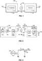
- FIG. 1illustrates a wireless transmission or charging system 100, in accordance with various exemplary embodiments of the present invention.
- Input power 102is provided to a transmitter 104 for generating a radiated field 106 for providing energy transfer.
- a receiver 108couples to the radiated field 106 and generates an output power 110 for storing or consumption by a device (not shown) coupled to the output power 110. Both the transmitter 104 and the receiver 108 are separated by a distance 112.
- transmitter 104 and receiver 108are configured according to a mutual resonant relationship and when the resonant frequency of receiver 108 and the resonant frequency of transmitter 104 are very close, transmission losses between the transmitter 104 and the receiver 108 are minimal when the receiver 108 is located in the "near-field" of the radiated field 106.
- Transmitter 104further includes a transmit antenna 114 for providing a means for energy transmission and receiver 108 further includes a receive antenna 118 for providing a means for energy reception.
- the transmit and receive antennasare sized according to applications and devices to be associated therewith. As stated, an efficient energy transfer occurs by coupling a large portion of the energy in the near-field of the transmitting antenna to a receiving antenna rather than propagating most of the energy in an electromagnetic wave to the far field. When in this near-field a coupling mode may be developed between the transmit antenna 114 and the receive antenna 118. The area around the antennas 114 and 118 where this near-field coupling may occur is referred to herein as a coupling-mode region.
- FIG. 2shows a simplified schematic diagram of a wireless power transfer system.
- the transmitter 104includes an oscillator 122, a power amplifier 124 and a filter and matching circuit 126.
- the oscillatoris configured to generate a signal at a desired frequency, which may be adjusted in response to adjustment signal 123.
- the oscillator signalmay be amplified by the power amplifier 124 with an amplification amount responsive to control signal 125.
- the filter and matching circuit 126may be included to filter out harmonics or other unwanted frequencies and match the impedance of the transmitter 104 to the transmit antenna 114.
- the receiver 108may include a matching circuit 132 and a rectifier and switching circuit 134 to generate a DC power output to charge a battery 136 as shown in FIG. 2 or power a device coupled to the receiver (not shown).
- the matching circuit 132may be included to match the impedance of the receiver 108 to the receive antenna 118.
- the receiver 108 and transmitter 104may communicate on a separate communication channel 119 ( e.g. , Bluetooth, zigbee, cellular, etc ).
- antennas used in exemplary embodimentsmay be configured as a "loop" antenna 150, which may also be referred to herein as a "magnetic" antenna.
- Loop antennasmay be configured to include an air core or a physical core such as a ferrite core. Air core loop antennas may be more tolerable to extraneous physical devices placed in the vicinity of the core. Furthermore, an air core loop antenna allows the placement of other components within the core area. In addition, an air core loop may more readily enable placement of the receive antenna 118 ( FIG. 2 ) within a plane of the transmit antenna 114 ( FIG. 2 ) where the coupled-mode region of the transmit antenna 114 ( FIG. 2 ) may be more powerful.
- the resonant frequency of the loop or magnetic antennasis based on the inductance and capacitance.
- Inductance in a loop antennais generally simply the inductance created by the loop, whereas, capacitance is generally added to the loop antenna's inductance to create a resonant structure at a desired resonant frequency.
- capacitor 152 and capacitor 154may be added to the antenna to create a resonant circuit that generates resonant signal 156. Accordingly, for larger diameter loop antennas, the size of capacitance needed to induce resonance decreases as the diameter or inductance of the loop increases. Furthermore, as the diameter of the loop or magnetic antenna increases, the efficient energy transfer area of the near-field increases.
- resonant circuitsare possible.
- a capacitormay be placed in parallel between the two terminals of the loop antenna.
- the resonant signal 156may be an input to the loop antenna 150.
- Exemplary embodiments of the inventioninclude coupling power between two antennas that are in the near-fields of each other.
- the near-fieldis an area around the antenna in which electromagnetic fields exist but may not propagate or radiate away from the antenna. They are typically confined to a volume that is near the physical volume of the antenna.
- magnetic type antennassuch as single and multi-turn loop antennas are used for both transmit (Tx) and receive (Rx) antenna systems since magnetic near-field amplitudes tend to be higher for magnetic type antennas in comparison to the electric near-fields of an electric-type antenna ( e.g ., a small dipole). This allows for potentially higher coupling between the pair.
- "electric" antennase . g ., dipoles and monopoles
- a combination of magnetic and electric antennasis also contemplated.
- the Tx antennacan be operated at a frequency that is low enough and with an antenna size that is large enough to achieve good coupling (e.g ., >-4 dB) to a small Rx antenna at significantly larger distances than allowed by far field and inductive approaches mentioned earlier. If the Tx antenna is sized correctly, high coupling levels (e.g. , -2 to -4 dB) can be achieved when the Rx antenna on a host device is placed within a coupling-mode region ( i.e. , in the near-field) of the driven Tx loop antenna.
- a coupling-mode regioni.e. , in the near-field
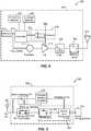
- FIG. 4is a simplified block diagram of a transmitter 200, in accordance with an exemplary embodiment of the present invention.
- the transmitter 200includes transmit circuitry 202 and a transmit antenna 204.
- transmit circuitry 202provides RF power to the transmit antenna 204 by providing an oscillating signal resulting in generation of near-field energy about the transmit antenna 204.
- transmitter 200may operate at the 13.56 MHz ISM band.
- Exemplary transmit circuitry 202includes a fixed impedance matching circuit 206 for matching the impedance of the transmit circuitry 202 (e.g ., 50 ohms) to the transmit antenna 204 and a low pass filter (LPF) 208 configured to reduce harmonic emissions to levels to prevent self-jamming of devices coupled to receivers 108 ( FIG. 1 ).
- LPFlow pass filter
- Other exemplary embodimentsmay include different filter topologies, including but not limited to, notch filters that attenuate specific frequencies while passing others and may include an adaptive impedance match, that can be varied based on measurable transmit metrics, such as output power to the antenna or DC current draw by the power amplifier.
- Transmit circuitry 202further includes a power amplifier 210 configured to drive an RF signal as determined by an oscillator 212.
- the transmit circuitrymay be comprised of discrete devices or circuits, or alternately, may be comprised of an integrated assembly.
- An exemplary RF power output from transmit antenna 204may be on the order of 2.5 Watts.
- Transmit circuitry 202further includes a controller 214 for enabling the oscillator 212 during transmit phases (or duty cycles) for specific receivers, for adjusting the frequency of the oscillator, and for adjusting the output power level for implementing a communication protocol for interacting with neighboring devices through their attached receivers.
- the transmit circuitry 202may further include a load sensing circuit 216 for detecting the presence or absence of active receivers in the vicinity of the near-field generated by transmit antenna 204.
- a load sensing circuit 216monitors the current flowing to the power amplifier 210, which is affected by the presence or absence of active receivers in the vicinity of the near-field generated by transmit antenna 204. Detection of changes to the loading on the power amplifier 210 are monitored by controller 214 for use in determining whether to enable the oscillator 212 for transmitting energy to communicate with an active receiver.
- Transmit antenna 204may be implemented as an antenna strip with the thickness, width and metal type selected to keep resistive losses low.
- the transmit antenna 204can generally be configured for association with a larger structure such as a table, mat, lamp or other less portable configuration. Accordingly, the transmit antenna 204 generally will not need "turns" in order to be of a practical dimension.
- An exemplary implementation of a transmit antenna 204may be "electrically small” (i.e. , fraction of the wavelength) and tuned to resonate at lower usable frequencies by using capacitors to define the resonant frequency.
- the transmit antenna 204may be larger in diameter, or length of side if a square loop, ( e.g. , 0.50 meters) relative to the receive antenna, the transmit antenna 204 will not necessarily need a large number of turns to obtain a reasonable capacitance.
- the transmitter 200may gather and track information about the whereabouts and status of receiver devices that may be associated with the transmitter 200.
- the transmitter circuitry 202may include a presence detector 280, an enclosed detector 290, or a combination thereof, connected to the controller 214 (also referred to as a processor herein).
- the controller 214may adjust an amount of power delivered by the amplifier 210 in response to presence signals from the presence detector 280 and the enclosed detector 290.
- the transmittermay receive power through a number of power sources, such as, for example, an AC-DC converter (not shown) to convert conventional AC power present in a building, a DC-DC converter (not shown) to convert a conventional DC power source to a voltage suitable for the transmitter 200, or directly from a conventional DC power source (not shown).
- FIG. 5is a simplified block diagram of a receiver 300, in accordance with an exemplary embodiment of the present invention.
- the receiver 300includes receive circuitry 302 and a receive antenna 304. Receiver 300 further couples to device 350 for providing received power thereto. It should be noted that receiver 300 is illustrated as being external to device 350 but may be integrated into device 350. Generally, energy is propagated wirelessly to receive antenna 304 and then coupled through receive circuitry 302 to device 350.
- Receive antenna 304is tuned to resonate at the same frequency, or near the same frequency, as transmit antenna 204 ( FIG. 4 ). Receive antenna 304 may be similarly dimensioned with transmit antenna 204 or may be differently sized based upon the dimensions of the associated device 350.
- device 350may be a portable electronic device having diametric or length dimension smaller that the diameter of length of transmit antenna 204.
- receive antenna 304may be implemented as a multi-turn antenna in order to reduce the capacitance value of a tuning capacitor (not shown) and increase the receive antenna's impedance.
- receive antenna 304may be placed around the substantial circumference of device 350 in order to maximize the antenna diameter and reduce the number of loop turns ( i.e. , windings) of the receive antenna and the inter-winding capacitance.
- Receive circuitry 302provides an impedance match to the receive antenna 304.
- Receive circuitry 302includes power conversion circuitry 306 for converting a received RF energy source into charging power for use by device 350.
- Power conversion circuitry 306includes an RF-to-DC converter 308 and may also in include a DC-to-DC converter 310.
- RF-to-DC converter 308rectifies the RF energy signal received at receive antenna 304 into a non-alternating power while DC-to-DC converter 310 converts the rectified RF energy signal into an energy potential (e.g ., voltage) that is compatible with device 350.
- Various RF-to-DC convertersare contemplated, including partial and full rectifiers, regulators, bridges, doublers, as well as linear and switching converters.
- Receive circuitry 302may further include switching circuitry 312 for connecting receive antenna 304 to the power conversion circuitry 306 or alternatively for disconnecting the power conversion circuitry 306. Disconnecting receive antenna 304 from power conversion circuitry 306 not only suspends charging of device 350, but also changes the "load” as “seen” by the transmitter 200 ( FIG. 2 ).
- transmitter 200includes load sensing circuit 216 which detects fluctuations in the bias current provided to transmitter power amplifier 210. Accordingly, transmitter 200 has a mechanism for determining when receivers are present in the transmitter's near-field.
- a receiverWhen multiple receivers 300 are present in a transmitter's near-field, it may be desirable to time-multiplex the loading and unloading of one or more receivers to enable other receivers to more efficiently couple to the transmitter.
- This "unloading" of a receiveris also known herein as a “cloaking.”
- a receivermay also be cloaked in order to eliminate coupling to other nearby receivers or to reduce loading on nearby transmitters.
- this switching between unloading and loading as controlled by receiver 300 and detected by transmitter 200provides a communication mechanism from receiver 300 to transmitter 200 as is explained more fully below.
- a protocolcan be associated with the switching which enables the sending of a message from receiver 300 to transmitter 200.
- a switching speedmay be on the order of 100 ⁇ sec.
- communication between the transmitter and the receiverrefers to a device sensing and charging control mechanism, rather than conventional two-way communication.
- the transmitteruses, for example, on/off keying of the transmitted signal to adjust whether energy is available in the near-filed.
- the receiversinterpret these changes in energy as a message from the transmitter.
- the receiveruses tuning and de-tuning of the receive antenna to adjust how much power is being accepted from the near-field.
- the transmittercan detect this difference in power used from the near-field and interpret these changes as signal forming a message from the receiver.
- Receive circuitry 302may further include signaling detector and beacon circuitry 314 used to identify received energy fluctuations, which may correspond to informational signaling from the transmitter to the receiver. Furthermore, signaling and beacon circuitry 314 may also be used to detect the transmission of a reduced RF signal energy (i.e. , a beacon signal) and to rectify the reduced RF signal energy into a nominal power for awakening either un-powered or power-depleted circuits within receive circuitry 302 in order to configure receive circuitry 302 for wireless charging.
- signaling detector and beacon circuitry 314used to identify received energy fluctuations, which may correspond to informational signaling from the transmitter to the receiver. Furthermore, signaling and beacon circuitry 314 may also be used to detect the transmission of a reduced RF signal energy (i.e. , a beacon signal) and to rectify the reduced RF signal energy into a nominal power for awakening either un-powered or power-depleted circuits within receive circuitry 302 in order to configure receive circuitry 302 for wireless charging.
- a reduced RF signal energy
- Receive circuitry 302further includes processor 316 for coordinating the processes of receiver 300 described herein including the control of switching circuitry 312 described herein. Cloaking of receiver 300 may also occur upon the occurrence of other events including detection of an external wired charging source (e.g ., wall/USB power) providing charging power to device 350.
- Processor 316in addition to controlling the cloaking of the receiver, may also monitor beacon circuitry 314 to determine a beacon state and extract messages sent from the transmitter. Processor 316 may also adjust DC-to-DC converter 310 for improved performance.
- FIG. 6shows a simplified schematic of a portion of transmit circuitry for carrying out messaging between a transmitter and a receiver.
- a means for communicationmay be enabled between the transmitter and the receiver.
- a power amplifier 210drives the transmit antenna 204 to generate the radiated field.
- the power amplifieris driven by a carrier signal 220 that is oscillating at a desired frequency for the transmit antenna 204.
- a transmit modulation signal 224is used to control the output of the power amplifier 210.
- the transmit circuitrycan send signals to receivers by using an ON/OFF keying process on the power amplifier 210.
- the transmit modulation signal 224when the transmit modulation signal 224 is asserted, the power amplifier 210 will drive the frequency of the carrier signal 220 out on the transmit antenna 204.
- the transmit modulation signal 224When the transmit modulation signal 224 is deactivated, the power amplifier will not drive any signal on the transmit antenna 204.
- the transmit circuitry of FIG. 6also includes a load sensing circuit 216 that supplies power to the power amplifier 210 and generates a receive signal 235.
- a voltage drop across resistor R sdevelops between the power in signal 226 and the power supply 228 to the power amplifier 210. Any change in the power consumed by the power amplifier 210 will cause a change in the voltage drop that will be amplified by differential amplifier 230.
- the transmit antennais in coupled mode with a receive antenna in a receiver (not shown in FIG. 6 ) the amount of current drawn by the power amplifier 210 will change. In other words, if no coupled mode resonance exist for the transmit antenna 204, the power required to drive the radiated field will be a first amount.
- the receive signal 235can indicate the presence of a receive antenna coupled to the transmit antenna 235 and can also detect signals sent from the receive antenna. Additionally, a change in receiver current draw will be observable in the transmitter's power amplifier current draw, and this change can be used to detect signals from the receive antennas.
- FIG. 7depicts a system 700 including at least one chargeable device 702 and a wireless charger 704, in accordance with an exemplary embodiment of the present invention.
- Chargeable device 702may comprise any known and suitable chargeable device.
- chargeable device 702may comprise a cellular telephone, a portable media player, a camera, a gaming device, a navigation device, a headset (e.g., a Bluetooth headset), a tool, a toy, or any combination thereof.
- Chargeable device 702may include at least one antenna 706, which may be configured to receive power wirelessly transmitted from a suitable wireless power source. More specifically, according to one exemplary embodiment, antenna 706 and an associated receiver, such as receiver 108 of FIG.
- chargeable device 702may include a coil (not shown) and an associated receiver, such as receiver 108 of FIG. 2 , which may be configured to receive wireless power transmitted from a wireless power source via inductive coupling. Additionally, chargeable device 702 may be configured to store received power within a battery 708 of chargeable device 702. Wireless charger 704 may include at least one transmit antenna 705 configured to wirelessly transmit power to at least one chargeable device (e.g., chargeable device 702). More specifically, transmit antenna 705 and an associated transmitter, such as transmitter 104 of FIG. 2 , may be configured to transmit wireless power to a receiver within an associated near-field region.
- a wireless power sourcee.g., wireless charger 704
- chargeable device 702may include a coil (not shown) and an associated receiver, such as receiver 108 of FIG. 2 , which may be configured to receive wireless power transmitted from a wireless power source via inductive coupling. Additionally, chargeable device 702 may be configured to store received power within a battery 708 of chargeable device 702. Wireless charger
- each of chargeable device 702 and wireless charger 704may be configured to wirelessly communicate with at least one other electronic device via associated antennas. More specifically, as an example, chargeable device 702 may be configured to establish a communication link with at least one other electronic device (e.g., wireless charger 704) and, upon establishing the communication link, may wirelessly receive data (e.g., audio files, data files, video files, or control signals) from the at least one other electronic device, wirelessly transmit data to the at least one other electronic device, or both.
- datae.g., audio files, data files, video files, or control signals
- wireless charger 704may be configured to establish a communication link with at least one other electronic device (e.g., chargeable device 702) and, upon establishing the communication link, may wirelessly receive data (e.g., audio files, data files, video files, or control signals) from the at least one other electronic device, wirelessly transmit data to the at least one other electronic device, or both.
- datae.g., audio files, data files, video files, or control signals
- wireless communication link 718exists between chargeable device 702 and wireless charger 704.
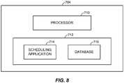
- FIG. 8illustrates a block diagram of charger 704.
- charger 704may include a processor 710 and memory 712.
- memory 712may include a scheduling application 714.
- Memory 712may also include a database 716.
- instructions implementing scheduling application 714may be tangibly embodied in a computer-readable medium, which may include one or more fixed or removable data storage devices, such as a zip drive, a floppy disc drive, a hard drive, a CD-ROM drive, tape drive, flash memory device, etc.
- scheduling application 714may include instructions which, when read and executed by processor 710, may cause processor 710 to perform the steps necessary to implement and/or use embodiments of the present invention.
- Scheduling application 714 and/or operating instructionsmay also be tangibly embodied in memory 712 and/or data communications devices, thereby making a computer program product or article of manufacture according to an embodiment the invention.
- the term "scheduling application” as used hereinis intended to encompass a computer program accessible from any computer readable device or media.
- charging attributeswhich may be used by wireless charger 704 in scheduling for transmission of wireless power, will now be described.
- charger 704and more specifically, scheduling application 714, may be configured for utilizing data to schedule for transmission of wireless power to one or more chargeable devices positioned within an associated charging region. More specifically and, as described more fully below, to create a charging schedule, scheduling application 714 may be configured to use, for example, one or more attributes related to one or more chargeable devices positioned within an associated charging region, one or more environment attributes associated with charger 704, one or more defined priority attributes associated with one or more chargeable devices, one or more defined priority attributes associated with one or more chargeable device users, or any combination thereof.
- scheduling application 714may be configured to utilize one or more static attributes associated with one or more chargeable devices.
- Static attributes associated with a chargeable devicemay identify, for example only, the type of chargeable device (e.g., a cellular telephone), a model of the chargeable device (e.g. Motorola), and a user of a chargeable device.
- static attributesmay identify a type of a battery (e.g., lithium ion) of a chargeable device, a model of a battery of a chargeable device, a charging capacity of a battery of a chargeable device, and a charging rate function of a battery of a chargeable device.
- Static attributesmay also identify a desired charging period duration of a battery of a chargeable device and a desired time gap between consecutive charging periods of a battery of a chargeable device.
- a charging rate function of a batterymay describe a relationship between a rate of charge (i.e., how fast the battery can be charged) and a charging state of a battery (i.e., the amount of charge stored in the battery).
- a rate of charge of a batterymay decrease as the amount of charge stored in the battery increases. Accordingly, as an amount of charge within a battery approaches a maximum level, the battery may require a lower rate of charging and, therefore, a charging time allocated to the battery may be decreased.
- a charging rate function of a batterymay be dependent on an age of the battery, a temperature of the battery, or both.
- scheduling application 714may be configured to utilize one or more dynamic attributes associated with one or more chargeable devices positioned within an associated charging region for generating and implementing a charging schedule.
- Dynamic attributesmay identify, for example only, a state of charge of a battery of a chargeable device, a temperature of a battery of a chargeable device, and an age of a battery of a chargeable device.
- Wireless charger 704may further be adapted to utilize one or more configurable attributes in generating and implementing a charging schedule.
- Configurable attributesmay identify, for example only, defined priority levels of one or more known chargeable device users, defined priority levels for one or more known chargeable devices, or any combination thereof.
- a cellular telephonemay have an assigned charging priority level that is higher than a charging priority level assigned to a portable media player.
- a first usere.g., an adult
- a second usere.g., a child
- scheduling application 714may be configured to utilize one or more environmental attributes associated with wireless charger 704 for generating and implementing a charging schedule for transmission of wireless power to one or more chargeable devices positioned within an associated charging region.
- an environmental attributemay identify the number of chargeable devices positioned within a charging region of wireless charger 704.
- an environmental attributemay identify interference patterns between two or more chargeable devices positioned within a charging region of wireless charger 704. It is noted that an interference pattern between two or more chargeable devices may depend on the types of chargeable devices, the types of batteries associated with the chargeable device, relative locations and/or orientations of the chargeable devices, or any combination thereof.
- attributesi.e., static attributes, dynamic attributes, configurable attributes, and environmental attributes
- charger 704may be stored within charger 704 (i.e., within database 716), may be conveyed to wireless charger 704 from one or more chargeable devices, may be retrieved from a remote database, may be derived by wireless charger 704 from other received attributes (i.e., attributes conveyed from one or more chargeable devices and/or attributes retrieved from a network), or any combination thereof.
- FIG. 9illustrates a system 730 including wireless charger 704, a plurality of chargeable devices 702 positioned within a charging region of wireless charger 704, and a remote database 720.
- wireless charger 704may be configured to wirelessly receive data (i.e., one or more attributes) from chargeable device 702 relating to one or more characteristics of chargeable device 702, one or more characteristics of a battery 708, or any combination thereof.
- chargeable device 702may wirelessly transmit, via communication link 718, one or more static attributes related thereto, one or more dynamic attributes related thereto, one or more configurable attributes related thereto, or any combination thereof, to wireless charger 704.
- wireless charger 704may be configured to retrieve data (i.e., one or more attributes) relating to one or more characteristics of chargeable device 702, one or more characteristics of battery 708, or any combination thereof. For example, upon detecting chargeable device 702, wireless charger 704 may be configured to retrieve associated attributes from chargeable device 702. As another example, upon chargeable device 702 being positioned within an associated charging region, wireless charger 704 may be configured to receive an attribute from chargeable device 702 identifying a model type of chargeable device 702. Moreover, upon receiving the attribute identifying the model type, wireless charger 704 may be configured to retrieve static attributes related to the model type from chargeable device 702, remote database 720, database 716, or a combination thereof.
- datai.e., one or more attributes
- wireless charger 704may be configured to retrieve associated attributes from chargeable device 702.
- wireless charger 704may be configured to receive an attribute from chargeable device 702 identifying a model type of chargeable device 702.
- wireless charger 704may be configured to retrieve static attributes related to the model type
- static attributes related to a chargeable devicemay identify, for example, the type of chargeable device (e.g., a cellular telephone) or an identity of a user of the chargeable device.
- wireless charger 704may be configured to retrieve static attributes related to battery 708 from remote database 720, database 716, chargeable device 702, or a combination thereof.
- static attributes associated with a batterymay indentify a type of the battery (e.g., lithium ion), a model of the battery, a charging capacity of the battery, a charging rate function of the battery, a desired charging period duration of the battery, a desired time gap between consecutive charging periods of the battery, and a charging rate function of the battery with respect to temperature.
- Wireless charger 704may further be configured to retrieve dynamic attributes from chargeable device 702 and associated therewith, prior to, or while providing wireless power to chargeable device 702. Moreover, wireless charger 704 may be configured to retrieve configurable attributes associated with chargeable device 702 from remote database 720, chargeable device 702, database 716, or a combination thereof.
- wireless charger 704 and, more specifically, database 716may be configured to store data (i.e., attributes) relating to one or more characteristics of chargeable device 702, one or more characteristics of battery 708, or any combination thereof.
- database 716may be configured to store static attributes relating to chargeable device 702, static attributes relating to battery 708, dynamic attributes relating to battery 708, or any combination thereof.
- database 716may be configured to store configurable attributes, such as, for example only, defined priority levels of one or more known users, defined priority levels for one or more known chargeable devices, or any combination thereof.
- Database 716may further be configured to store data related to environmental attributes such as, for example only, the number of chargeable devices positioned within a charging region of wireless charger 704, or interference patterns between two or more chargeable devices positioned within a charging region of wireless charger 704.
- wireless charger 704may be configured to derive data (i.e., attributes) relating to one or more characteristics of chargeable device types, one or more characteristics of battery types, or any combination thereof, based on other known attributes. For example only, upon receipt of an attribute identifying a model of a battery, wireless charger 704 may be configured to determine one or more static attributes of the battery, such as, for example only, the battery capacity or the charging rate function of the battery. As another example, wireless charger 704 may be configured to estimate a current state of charge of a battery of a chargeable device based on an initial state of charge of the battery, a charging rate of the battery, and the elapsed charging duration. Wireless charger 704 may also be configured to derive one or more environmental attributes by, for example, sensing a number of chargeable devices positioned within an associated charging region, sensing interference patterns between two or more chargeable devices, or any combination thereof.
- datai.e., attributes
- wireless charger 704may be configured to determine one or more static attributes of the battery, such as,
- wireless charger 704may be configured to retrieve available static attributes, dynamic attributes, and configurable attributes from chargeable device 702.
- chargeable device 702may convey one or more static attributes to wireless charger 704 prior to receiving a charge therefrom.
- each chargeable device 702may convey one or more dynamic attributes to wireless charger 704.
- each chargeable device 702may be configured to send one or more dynamic attributes to wireless charger 704 on a regular basis or as needed during the charging process.
- scheduling application 714may be configured to update a charging schedule at anytime during a charging process.
- chargeable device 702may convey a key static attribute (e.g., an attribute identifying the model of battery 708) to wireless charger 704 prior to receiving a charge therefrom. Thereafter, based on the key attribute, wireless charger 704 may be configured to retrieve one or more other static attributes associated with chargeable device 702 and stored within database 716. In yet another exemplary embodiment, based on the key attribute, wireless charger 704 may be configured retrieve one or more other static attributes, which are associated with chargeable device 702, from remote database 720.
- a key static attributee.g., an attribute identifying the model of battery 708
- wireless charger 704may be configured to attempt to retrieve one or more static attributes within database 716 and, if at least one attribute of the one or more static attributes is not found within database 716, wireless charger 704 may attempt to retrieve the at least one static attribute from remote database 720.
- chargeable device 702may convey one or more configurable attributes to wireless charger 704.
- chargeable device 702may convey its priority level to wireless charger.
- wireless charger 704may be configured to derive one or more configurable attributes locally, or attempt to retrieve one or more configurable attributes from remote database 720 based on one or more other attributes, such as, a device type, a device identity, or a user identity.
- FIG. 10illustrates wireless charger 704 and a plurality of chargeable devices 702A-D positioned within a charging region 707 of wireless charger 704.
- a wireless power transmission schedulemay be based on a time-domain based sequence wherein time slots may be allocated for charging one or more chargeable devices. It is noted that for each allocated charging time slot, wireless charger 704 may wirelessly convey power to one or more chargeable devices. It is further noted that chargeable devices may be "cloaked" during time slots in which they are not scheduled to receive wireless power.
- scheduling application 714may be configured to schedule for transmission of wireless power to each chargeable device 702A-D in a "round robin" approach. Accordingly, each chargeable device 702A-D may receive power for equal durations of time. In another exemplary embodiment, scheduling application 714 (see FIG. 8 ) may be configured to determine an order in which to charge chargeable devices 702A-D and, furthermore, may determine a charging time duration for each chargeable device 702A-D.
- scheduling application 714may determine an order in which to charge chargeable devices 702A-D and/or a charging time duration for each chargeable device 702A-D based on one or more static attributes associated with one or more of chargeable devices 702A-D, one or more dynamic attributes associated with one or more of chargeable devices 702A-D, one or more configurable attributes associated with one or more of chargeable devices 702A-D, one or more environmental attributes associated with wireless charger 704, or any combination thereof.
- scheduling application 714may be configured to determine an order in which to charge chargeable devices 704A-D and/or charging time durations for each chargeable device 704A-D according to weighted factors assigned to each chargeable device.
- a weighted factor assigned to a chargeable devicemay be based on a device priority associated with the chargeable device, a user priority associated with the chargeable device, a charging rate of the chargeable device, a time duration required for the chargeable device to reach a maximum charge, or any combination thereof.
- scheduling application 714may be configured to schedule chargeable device 704A to receive wireless power first, and for a time duration of T/2. Furthermore, scheduling application 714 may be configured to schedule chargeable device 704B to receive wireless power second, and for a time duration of T/4.
- scheduling application 714may be configured to schedule each of chargeable device 704C and chargeable device 704D to receive wireless for a time duration of T/8. It is noted that, in this example, an order of providing wireless power to each of chargeable device 704C and chargeable device 704D may be determined by one or more other attributes of chargeable device 704C and chargeable device 704D (e.g., charging rates or device priorities), or wireless power may be provided to each of chargeable device 704C and chargeable device 704D in a random, "round robin" approach. It is noted that a weighted factor assigned to a chargeable device may be dependent on one or more attributes associated with the chargeable device.
- scheduling application 714may determine an order in which to charge chargeable devices 704A-D according to priority levels assigned to each chargeable device 704A-D.
- Priority levels assigned to each chargeable device 704A-Dmay be dependent on device priorities (e.g., a cellular telephone, which has a higher device priority than a toy, may be charged prior to the toy), user priorities (e.g., an adult's cellular telephone, which has a higher user priority than a child's cellular telephone, may be charged prior to the child's cellular telephone), charging efficiencies (e.g., chargeable devices having a higher charging efficiency would be charged before chargeable devices having lower charging efficiencies), charging time durations for maximum charge (e.g., a chargeable device that requires a longer time charging duration to reach a maximum charge may be charged before a chargeable device that requires a shorter time charging duration to reach a maximum charge), charging levels (e.g., a chargeable device that is 20% charged may be charged before a chargeable device
- chargeable device 704Ahas a device priority level higher than chargeable device 704B
- chargeable device 704Bhas a device priority level higher than chargeable device 704C
- chargeable device 704Chas a device priority level higher than chargeable device 704D.
- scheduling application 714may schedule to convey wireless power to chargeable device 704A during a first time slot and for a time duration required to reach a threshold charge (e.g., full charge), convey wireless power to chargeable device 704B during a second time slot and for a time duration required to reach a threshold charge, convey wireless power to chargeable device 704C during a third time slot and for a time duration required to reach a threshold charge, and convey wireless power to chargeable device 704D during a fourth time slot and for a time duration required to reach a threshold charge.
- a threshold chargee.g., full charge
- scheduling application 714may schedule to convey wireless power to chargeable device 704D during a first time slot, convey wireless power to chargeable device 704C during a second time slot, convey wireless power to chargeable device 704B during a third time slot, and convey wireless power to chargeable device 704A during a fourth time slot.
- scheduling application 714may be configured to determine a schedule for providing wireless power based on a plurality of priority level designations (e.g., device priority levels and charging rates), a plurality of weighted factor designations, or any combination thereof. For example, two chargeable devices 702 having equal user priority levels may be provided power in an order based on charging rates. As another example, two chargeable devices 702 including batteries having equal priority levels may be provided power according to a round robin approach or a weighted factor designation. Moreover, scheduling application 714 may be configured to schedule for transmission of wireless power simultaneously to a plurality of chargeable devices based on environmental attributes, such as interference patterns between two or more devices positioned within a charging region of wireless charger 704.
- a plurality of priority level designationse.g., device priority levels and charging rates
- weighted factor designationse.g., weighted factor designations
- FIG. 11illustrates a system 800 including a plurality of chargeable devices 802 and a wireless charger 804.
- Each chargeable device 802includes a processor 809, a database 806, a transmitter 811, and a battery 808.
- wireless charger 804obtain attributes related to each chargeable device 802.
- each chargeable device 802, and more specifically, processor 809is configured to utilize attributes associated therewith and stored within associated database 806 to determine one or more desired associated charging parameters.
- a charging parametermay include a charging rate, a charging duration, or a combination thereof. It is noted that the desired charging parameters may chosen to optimize a charging process of chargeable device 802.
- chargeable device 802may transmit, via transmitter 811, a charging request to wireless charger 804 via communication link 818.
- a charging requestmay include a desired rate of charge and a maximum rate of charge. More specifically, in an example wherein battery 808 is close to a maximum charge, chargeable device 802 may transmit a signal, via communication link 818, to wireless charger 804 requesting infrequent short bursts of charge.
- a charging requestmay also include a time duration when the request is valid.
- wireless charger 804may determine a charging schedule in accordance with one or more of the exemplary embodiments described herein. It is noted that wireless charger 804 may include processor 710 and scheduling application 714.
- chargeable device 802may be configured to access a remote database 820 to obtain up-to-date information (e.g., attributes) associated with battery 808.
- FIG. 12is a flowchart illustrating a method 680, in accordance with one or more exemplary embodiments.
- Method 680may include scheduling for transmission of wireless power to one or more chargeable devices of the plurality of chargeable devices positioned within a charging region of a wireless charger based on at least attribute associated with at least one of the wireless charger and at least one chargeable device of the plurality of chargeable devices (depicted by numeral 682).
- Scheduling for transmission of wireless powermay enable for maximization of wireless power transfer efficiency, prioritization of chargeable devices, prioritization of chargeable device users, and increased battery-life protection and fairness in charging.
- DSPDigital Signal Processor
- ASICApplication Specific Integrated Circuit
- FPGAField Programmable Gate Array
- a general purpose processormay be a microprocessor, but in the alternative, the processor may be any conventional processor, controller, microcontroller, or state machine.
- a processormay also be implemented as a combination of computing devices, e.g ., a combination of a DSP and a microprocessor, a plurality of microprocessors, one or more microprocessors in conjunction with a DSP core, or any other such configuration.
- a software modulemay reside in Random Access Memory (RAM), flash memory, Read Only Memory (ROM), Electrically Programmable ROM (EPROM), Electrically Erasable Programmable ROM (EEPROM), registers, hard disk, a removable disk, a CD-ROM, or any other form of storage medium known in the art.
- An exemplary storage mediumis coupled to the processor such that the processor can read information from, and write information to, the storage medium.
- the storage mediummay be integral to the processor.
- the processor and the storage mediummay reside in an ASIC.
- the ASICmay reside in a user terminal.
- the processor and the storage mediummay reside as discrete components in a user terminal.
- the functions describedmay be implemented in hardware, software, firmware, or any combination thereof. If implemented in software, the functions may be stored on or transmitted over as one or more instructions or code on a computer-readable medium.
- Computer-readable mediaincludes both computer storage media and communication media including any medium that facilitates transfer of a computer program from one place to another.
- a storage mediamay be any available media that can be accessed by a computer.
- such computer-readable mediacan comprise RAM, ROM, EEPROM, CD-ROM or other optical disk storage, magnetic disk storage or other magnetic storage devices, or any other medium that can be used to carry or store desired program code in the form of instructions or data structures and that can be accessed by a computer.
- any connectionis properly termed a computer-readable medium.
- the softwareis transmitted from a website, server, or other remote source using a coaxial cable, fiber optic cable, twisted pair, digital subscriber line (DSL), or wireless technologies such as infrared, radio, and microwave
- the coaxial cable, fiber optic cable, twisted pair, DSL, or wireless technologiessuch as infrared, radio, and microwave are included in the definition of medium.
- Disk and discincludes compact disc (CD), laser disc, optical disc, digital versatile disc (DVD), floppy disk and blu-ray disc where disks usually reproduce data magnetically, while discs reproduce data optically with lasers. Combinations of the above should also be included within the scope of computer-readable media.
Landscapes
- Engineering & Computer Science (AREA)
- Computer Networks & Wireless Communication (AREA)
- Power Engineering (AREA)
- Signal Processing (AREA)
- Charge And Discharge Circuits For Batteries Or The Like (AREA)
- Secondary Cells (AREA)
Description
- The present invention relates generally to wireless power, and more specifically to scheduling for transmission of wireless power from a wireless charger to a plurality of chargeable devices.
- Typically, each battery powered device requires its own charger and power source, which is usually an AC power outlet. This becomes unwieldy when many devices need charging.
- Approaches are being developed that use over the air power transmission between a transmitter and the device to be charged. These generally fall into two categories. One is based on the coupling of plane wave radiation (also called far- field radiation) between a transmit antenna and receive antenna on the device to be charged which collects the radiated power and rectifies it for charging the battery. Antennas may be of resonant length in order to improve the coupling efficiency. This approach suffers from the fact that the power coupling falls off quickly with distance between the antennas. So charging over reasonable distances (e.g., >1-2m) becomes difficult. Additionally, since the system radiates plane waves, unintentional radiation can interfere with other systems if not properly controlled through filtering.
US2004/145342 discloses a method and apparatus is used for adaptive inductive charging of a device. Charging includes detecting the presence of a device capable of receiving an inductive charge, determining a set of parameters for inductively charging the device, and transmitting an inductive charge corresponding to the set of parameters for charging the device.- Other approaches are based on inductive coupling between a transmit antenna embedded, for example, in a "charging" mat or surface and a receive antenna plus rectifying circuit embedded in the host device to be charged. This approach has the disadvantage that the spacing between transmit and receive antennas must be very close (e.g. mms). Though this approach may have the capability to simultaneously charge multiple devices in the same area, this area is typically small, hence the user must locate the devices to a specific area.
- A need exists for devices configured for determining a schedule for transmission of wireless power to multiple chargeable devices. More specifically, a need exists for devices configured for determining a schedule for transmission of wireless power from a wireless charger to multiple chargeable devices based upon one or more charging attributes associated with the chargeable devices, the wireless charger, or both.
- The invention is defined by the features of device claim 1 and corresponding method claim 9. The dependent claims recite advantageous embodiments of the invention.
FIG. 1 shows a simplified block diagram of a wireless power transmission system.FIG. 2 shows a simplified schematic diagram of a wireless power transmission system.FIG. 3 shows a schematic diagram of a loop antenna for use in exemplary embodiments of the present invention.FIG. 4 is a simplified block diagram of a transmitter, in accordance with an exemplary embodiment of the present invention.FIG. 5 is a simplified block diagram of a receiver, in accordance with an exemplary embodiment of the present invention.FIG. 6 shows a simplified schematic of a portion of transmit circuitry for carrying out messaging between a transmitter and a receiver.FIG. 7 illustrates a system including a chargeable device and a wireless charger, in accordance with an exemplary embodiment of the present invention.FIG. 8 is a block diagram of a wireless charger, according to an exemplary embodiment of the present invention.FIG. 9 illustrates a system including a wireless charger, a plurality of chargeable devices, and a remote database, in accordance with an exemplary embodiment of the present invention.FIG. 10 illustrates a wireless charger and a plurality of chargeable devices, according to an exemplary embodiment of the present invention.FIG. 11 illustrates another system including a wireless charger, a plurality of chargeable devices, and a remote database, according to an exemplary embodiment of the present invention.FIG. 12 is a flowchart illustrating a method, in accordance with an exemplary embodiment of the present invention.- The word "exemplary" is used herein to mean "serving as an example, instance, or illustration." Any embodiment described herein as "exemplary" is not necessarily to be construed as preferred or advantageous over other embodiments.
- The detailed description set forth below in connection with the appended drawings is intended as a description of exemplary embodiments of the present invention and is not intended to represent the only embodiments in which the present invention can be practiced. The term "exemplary" used throughout this description means "serving as an example, instance, or illustration," and should not necessarily be construed as preferred or advantageous over other exemplary embodiments. The detailed description includes specific details for the purpose of providing a thorough understanding of the exemplary embodiments of the invention. It will be apparent to those skilled in the art that the exemplary embodiments of the invention may be practiced without these specific details. In some instances, well-known structures and devices are shown in block diagram form in order to avoid obscuring the novelty of the exemplary embodiments presented herein.
- The words "wireless power" is used herein to mean any form of energy associated with electric fields, magnetic fields, electromagnetic fields, or otherwise that is transmitted between from a transmitter to a receiver without the use of physical electromagnetic conductors.
FIG. 1 illustrates a wireless transmission orcharging system 100, in accordance with various exemplary embodiments of the present invention.Input power 102 is provided to atransmitter 104 for generating aradiated field 106 for providing energy transfer. Areceiver 108 couples to theradiated field 106 and generates anoutput power 110 for storing or consumption by a device (not shown) coupled to theoutput power 110. Both thetransmitter 104 and thereceiver 108 are separated by adistance 112. In one exemplary embodiment,transmitter 104 andreceiver 108 are configured according to a mutual resonant relationship and when the resonant frequency ofreceiver 108 and the resonant frequency oftransmitter 104 are very close, transmission losses between thetransmitter 104 and thereceiver 108 are minimal when thereceiver 108 is located in the "near-field" of theradiated field 106.- Transmitter 104 further includes a
transmit antenna 114 for providing a means for energy transmission andreceiver 108 further includes areceive antenna 118 for providing a means for energy reception. The transmit and receive antennas are sized according to applications and devices to be associated therewith. As stated, an efficient energy transfer occurs by coupling a large portion of the energy in the near-field of the transmitting antenna to a receiving antenna rather than propagating most of the energy in an electromagnetic wave to the far field. When in this near-field a coupling mode may be developed between thetransmit antenna 114 and the receiveantenna 118. The area around theantennas FIG. 2 shows a simplified schematic diagram of a wireless power transfer system. Thetransmitter 104 includes anoscillator 122, apower amplifier 124 and a filter and matchingcircuit 126. The oscillator is configured to generate a signal at a desired frequency, which may be adjusted in response toadjustment signal 123. The oscillator signal may be amplified by thepower amplifier 124 with an amplification amount responsive to controlsignal 125. The filter and matchingcircuit 126 may be included to filter out harmonics or other unwanted frequencies and match the impedance of thetransmitter 104 to thetransmit antenna 114.- The
receiver 108 may include amatching circuit 132 and a rectifier andswitching circuit 134 to generate a DC power output to charge abattery 136 as shown inFIG. 2 or power a device coupled to the receiver (not shown). The matchingcircuit 132 may be included to match the impedance of thereceiver 108 to the receiveantenna 118. Thereceiver 108 andtransmitter 104 may communicate on a separate communication channel 119 (e.g., Bluetooth, zigbee, cellular,etc). - As illustrated in
FIG. 3 , antennas used in exemplary embodiments may be configured as a "loop"antenna 150, which may also be referred to herein as a "magnetic" antenna. Loop antennas may be configured to include an air core or a physical core such as a ferrite core. Air core loop antennas may be more tolerable to extraneous physical devices placed in the vicinity of the core. Furthermore, an air core loop antenna allows the placement of other components within the core area. In addition, an air core loop may more readily enable placement of the receive antenna 118 (FIG. 2 ) within a plane of the transmit antenna 114 (FIG. 2 ) where the coupled-mode region of the transmit antenna 114 (FIG. 2 ) may be more powerful. - As stated, efficient transfer of energy between the
transmitter 104 andreceiver 108 occurs during matched or nearly matched resonance between thetransmitter 104 and thereceiver 108. However, even when resonance between thetransmitter 104 andreceiver 108 are not matched, energy may be transferred at a lower efficiency. Transfer of energy occurs by coupling energy from the near-field of the transmitting antenna to the receiving antenna residing in the neighborhood where this near-field is established rather than propagating the energy from the transmitting antenna into free space. - The resonant frequency of the loop or magnetic antennas is based on the inductance and capacitance. Inductance in a loop antenna is generally simply the inductance created by the loop, whereas, capacitance is generally added to the loop antenna's inductance to create a resonant structure at a desired resonant frequency. As a non-limiting example,
capacitor 152 andcapacitor 154 may be added to the antenna to create a resonant circuit that generatesresonant signal 156. Accordingly, for larger diameter loop antennas, the size of capacitance needed to induce resonance decreases as the diameter or inductance of the loop increases. Furthermore, as the diameter of the loop or magnetic antenna increases, the efficient energy transfer area of the near-field increases. Of course, other resonant circuits are possible. As another non-limiting example, a capacitor may be placed in parallel between the two terminals of the loop antenna. In addition, those of ordinary skill in the art will recognize that for transmit antennas theresonant signal 156 may be an input to theloop antenna 150. - Exemplary embodiments of the invention include coupling power between two antennas that are in the near-fields of each other. As stated, the near-field is an area around the antenna in which electromagnetic fields exist but may not propagate or radiate away from the antenna. They are typically confined to a volume that is near the physical volume of the antenna. In the exemplary embodiments of the invention, magnetic type antennas such as single and multi-turn loop antennas are used for both transmit (Tx) and receive (Rx) antenna systems since magnetic near-field amplitudes tend to be higher for magnetic type antennas in comparison to the electric near-fields of an electric-type antenna (e.g., a small dipole). This allows for potentially higher coupling between the pair. Furthermore, "electric" antennas (e.g., dipoles and monopoles) or a combination of magnetic and electric antennas is also contemplated.
- The Tx antenna can be operated at a frequency that is low enough and with an antenna size that is large enough to achieve good coupling (e.g., >-4 dB) to a small Rx antenna at significantly larger distances than allowed by far field and inductive approaches mentioned earlier. If the Tx antenna is sized correctly, high coupling levels (e.g., -2 to -4 dB) can be achieved when the Rx antenna on a host device is placed within a coupling-mode region (i.e., in the near-field) of the driven Tx loop antenna.
FIG. 4 is a simplified block diagram of atransmitter 200, in accordance with an exemplary embodiment of the present invention. Thetransmitter 200 includes transmitcircuitry 202 and a transmitantenna 204. Generally, transmitcircuitry 202 provides RF power to the transmitantenna 204 by providing an oscillating signal resulting in generation of near-field energy about the transmitantenna 204. By way of example,transmitter 200 may operate at the 13.56 MHz ISM band.- Exemplary transmit
circuitry 202 includes a fixedimpedance matching circuit 206 for matching the impedance of the transmit circuitry 202 (e.g., 50 ohms) to the transmitantenna 204 and a low pass filter (LPF) 208 configured to reduce harmonic emissions to levels to prevent self-jamming of devices coupled to receivers 108 (FIG. 1 ). Other exemplary embodiments may include different filter topologies, including but not limited to, notch filters that attenuate specific frequencies while passing others and may include an adaptive impedance match, that can be varied based on measurable transmit metrics, such as output power to the antenna or DC current draw by the power amplifier. Transmitcircuitry 202 further includes apower amplifier 210 configured to drive an RF signal as determined by anoscillator 212. The transmit circuitry may be comprised of discrete devices or circuits, or alternately, may be comprised of an integrated assembly. An exemplary RF power output from transmitantenna 204 may be on the order of 2.5 Watts. - Transmit
circuitry 202 further includes acontroller 214 for enabling theoscillator 212 during transmit phases (or duty cycles) for specific receivers, for adjusting the frequency of the oscillator, and for adjusting the output power level for implementing a communication protocol for interacting with neighboring devices through their attached receivers. - The transmit
circuitry 202 may further include aload sensing circuit 216 for detecting the presence or absence of active receivers in the vicinity of the near-field generated by transmitantenna 204. By way of example, aload sensing circuit 216 monitors the current flowing to thepower amplifier 210, which is affected by the presence or absence of active receivers in the vicinity of the near-field generated by transmitantenna 204. Detection of changes to the loading on thepower amplifier 210 are monitored bycontroller 214 for use in determining whether to enable theoscillator 212 for transmitting energy to communicate with an active receiver. - Transmit
antenna 204 may be implemented as an antenna strip with the thickness, width and metal type selected to keep resistive losses low. In a conventional implementation, the transmitantenna 204 can generally be configured for association with a larger structure such as a table, mat, lamp or other less portable configuration. Accordingly, the transmitantenna 204 generally will not need "turns" in order to be of a practical dimension. An exemplary implementation of a transmitantenna 204 may be "electrically small" (i.e., fraction of the wavelength) and tuned to resonate at lower usable frequencies by using capacitors to define the resonant frequency. In an exemplary application where the transmitantenna 204 may be larger in diameter, or length of side if a square loop, (e.g., 0.50 meters) relative to the receive antenna, the transmitantenna 204 will not necessarily need a large number of turns to obtain a reasonable capacitance. - The
transmitter 200 may gather and track information about the whereabouts and status of receiver devices that may be associated with thetransmitter 200. Thus, thetransmitter circuitry 202 may include apresence detector 280, an enclosed detector 290, or a combination thereof, connected to the controller 214 (also referred to as a processor herein). Thecontroller 214 may adjust an amount of power delivered by theamplifier 210 in response to presence signals from thepresence detector 280 and the enclosed detector 290. The transmitter may receive power through a number of power sources, such as, for example, an AC-DC converter (not shown) to convert conventional AC power present in a building, a DC-DC converter (not shown) to convert a conventional DC power source to a voltage suitable for thetransmitter 200, or directly from a conventional DC power source (not shown). FIG. 5 is a simplified block diagram of areceiver 300, in accordance with an exemplary embodiment of the present invention. Thereceiver 300 includes receivecircuitry 302 and a receiveantenna 304.Receiver 300 further couples todevice 350 for providing received power thereto. It should be noted thatreceiver 300 is illustrated as being external todevice 350 but may be integrated intodevice 350. Generally, energy is propagated wirelessly to receiveantenna 304 and then coupled through receivecircuitry 302 todevice 350.- Receive
antenna 304 is tuned to resonate at the same frequency, or near the same frequency, as transmit antenna 204 (FIG. 4 ). Receiveantenna 304 may be similarly dimensioned with transmitantenna 204 or may be differently sized based upon the dimensions of the associateddevice 350. By way of example,device 350 may be a portable electronic device having diametric or length dimension smaller that the diameter of length of transmitantenna 204. In such an example, receiveantenna 304 may be implemented as a multi-turn antenna in order to reduce the capacitance value of a tuning capacitor (not shown) and increase the receive antenna's impedance. By way of example, receiveantenna 304 may be placed around the substantial circumference ofdevice 350 in order to maximize the antenna diameter and reduce the number of loop turns (i.e., windings) of the receive antenna and the inter-winding capacitance. - Receive
circuitry 302 provides an impedance match to the receiveantenna 304. Receivecircuitry 302 includespower conversion circuitry 306 for converting a received RF energy source into charging power for use bydevice 350.Power conversion circuitry 306 includes an RF-to-DC converter 308 and may also in include a DC-to-DC converter 310. RF-to-DC converter 308 rectifies the RF energy signal received at receiveantenna 304 into a non-alternating power while DC-to-DC converter 310 converts the rectified RF energy signal into an energy potential (e.g., voltage) that is compatible withdevice 350. Various RF-to-DC converters are contemplated, including partial and full rectifiers, regulators, bridges, doublers, as well as linear and switching converters. - Receive
circuitry 302 may further include switchingcircuitry 312 for connecting receiveantenna 304 to thepower conversion circuitry 306 or alternatively for disconnecting thepower conversion circuitry 306. Disconnecting receiveantenna 304 frompower conversion circuitry 306 not only suspends charging ofdevice 350, but also changes the "load" as "seen" by the transmitter 200 (FIG. 2 ). - As disclosed above,
transmitter 200 includesload sensing circuit 216 which detects fluctuations in the bias current provided totransmitter power amplifier 210. Accordingly,transmitter 200 has a mechanism for determining when receivers are present in the transmitter's near-field. - When
multiple receivers 300 are present in a transmitter's near-field, it may be desirable to time-multiplex the loading and unloading of one or more receivers to enable other receivers to more efficiently couple to the transmitter. This "unloading" of a receiver is also known herein as a "cloaking." A receiver may also be cloaked in order to eliminate coupling to other nearby receivers or to reduce loading on nearby transmitters. Furthermore, this switching between unloading and loading as controlled byreceiver 300 and detected bytransmitter 200 provides a communication mechanism fromreceiver 300 totransmitter 200 as is explained more fully below. Additionally, a protocol can be associated with the switching which enables the sending of a message fromreceiver 300 totransmitter 200. By way of example, a switching speed may be on the order of 100 µsec. - In an exemplary embodiment, communication between the transmitter and the receiver refers to a device sensing and charging control mechanism, rather than conventional two-way communication. In other words, the transmitter uses, for example, on/off keying of the transmitted signal to adjust whether energy is available in the near-filed. The receivers interpret these changes in energy as a message from the transmitter. From the receiver side, the receiver uses tuning and de-tuning of the receive antenna to adjust how much power is being accepted from the near-field. The transmitter can detect this difference in power used from the near-field and interpret these changes as signal forming a message from the receiver.
- Receive
circuitry 302 may further include signaling detector andbeacon circuitry 314 used to identify received energy fluctuations, which may correspond to informational signaling from the transmitter to the receiver. Furthermore, signaling andbeacon circuitry 314 may also be used to detect the transmission of a reduced RF signal energy (i.e., a beacon signal) and to rectify the reduced RF signal energy into a nominal power for awakening either un-powered or power-depleted circuits within receivecircuitry 302 in order to configure receivecircuitry 302 for wireless charging. - Receive
circuitry 302 further includesprocessor 316 for coordinating the processes ofreceiver 300 described herein including the control of switchingcircuitry 312 described herein. Cloaking ofreceiver 300 may also occur upon the occurrence of other events including detection of an external wired charging source (e.g., wall/USB power) providing charging power todevice 350.Processor 316, in addition to controlling the cloaking of the receiver, may also monitorbeacon circuitry 314 to determine a beacon state and extract messages sent from the transmitter.Processor 316 may also adjust DC-to-DC converter 310 for improved performance. FIG. 6 shows a simplified schematic of a portion of transmit circuitry for carrying out messaging between a transmitter and a receiver. In some exemplary embodiments of the present invention, a means for communication may be enabled between the transmitter and the receiver. InFIG. 6 apower amplifier 210 drives the transmitantenna 204 to generate the radiated field. The power amplifier is driven by acarrier signal 220 that is oscillating at a desired frequency for the transmitantenna 204. A transmitmodulation signal 224 is used to control the output of thepower amplifier 210.- The transmit circuitry can send signals to receivers by using an ON/OFF keying process on the
power amplifier 210. In other words, when the transmitmodulation signal 224 is asserted, thepower amplifier 210 will drive the frequency of thecarrier signal 220 out on the transmitantenna 204. When the transmitmodulation signal 224 is deactivated, the power amplifier will not drive any signal on the transmitantenna 204. - The transmit circuitry of
FIG. 6 also includes aload sensing circuit 216 that supplies power to thepower amplifier 210 and generates a receivesignal 235. In theload sensing circuit 216, a voltage drop across resistor Rs develops between the power insignal 226 and thepower supply 228 to thepower amplifier 210. Any change in the power consumed by thepower amplifier 210 will cause a change in the voltage drop that will be amplified bydifferential amplifier 230. When the transmit antenna is in coupled mode with a receive antenna in a receiver (not shown inFIG. 6 ) the amount of current drawn by thepower amplifier 210 will change. In other words, if no coupled mode resonance exist for the transmitantenna 204, the power required to drive the radiated field will be a first amount. If a coupled mode resonance exists, the amount of power consumed by thepower amplifier 210 will go up because much of the power is being coupled into the receive antenna. Thus, the receivesignal 235 can indicate the presence of a receive antenna coupled to the transmitantenna 235 and can also detect signals sent from the receive antenna. Additionally, a change in receiver current draw will be observable in the transmitter's power amplifier current draw, and this change can be used to detect signals from the receive antennas. - Details of some exemplary embodiments for cloaking signals, beacon signals, and circuits for generating these signals can be seen in
U.S. Utility Patent Application 12/249,873 U.S. Utility Patent Application 12/249,861 - Details of exemplary communication mechanisms and protocols can be seen in
U.S. Utility Patent Application 12/249,866 FIG. 7 depicts asystem 700 including at least onechargeable device 702 and awireless charger 704, in accordance with an exemplary embodiment of the present invention.Chargeable device 702 may comprise any known and suitable chargeable device. As non-limiting examples,chargeable device 702 may comprise a cellular telephone, a portable media player, a camera, a gaming device, a navigation device, a headset (e.g., a Bluetooth headset), a tool, a toy, or any combination thereof.Chargeable device 702 may include at least oneantenna 706, which may be configured to receive power wirelessly transmitted from a suitable wireless power source. More specifically, according to one exemplary embodiment,antenna 706 and an associated receiver, such asreceiver 108 ofFIG. 2 , may be configured to receive wireless power transmitted from a wireless power source (e.g., wireless charger 704) positioned within an associated near-field region. Furthermore,chargeable device 702 may include a coil (not shown) and an associated receiver, such asreceiver 108 ofFIG. 2 , which may be configured to receive wireless power transmitted from a wireless power source via inductive coupling. Additionally,chargeable device 702 may be configured to store received power within abattery 708 ofchargeable device 702.Wireless charger 704 may include at least one transmitantenna 705 configured to wirelessly transmit power to at least one chargeable device (e.g., chargeable device 702). More specifically, transmitantenna 705 and an associated transmitter, such astransmitter 104 ofFIG. 2 , may be configured to transmit wireless power to a receiver within an associated near-field region.- Furthermore, each of
chargeable device 702 andwireless charger 704 may be configured to wirelessly communicate with at least one other electronic device via associated antennas. More specifically, as an example,chargeable device 702 may be configured to establish a communication link with at least one other electronic device (e.g., wireless charger 704) and, upon establishing the communication link, may wirelessly receive data (e.g., audio files, data files, video files, or control signals) from the at least one other electronic device, wirelessly transmit data to the at least one other electronic device, or both. Similarly,wireless charger 704 may be configured to establish a communication link with at least one other electronic device (e.g., chargeable device 702) and, upon establishing the communication link, may wirelessly receive data (e.g., audio files, data files, video files, or control signals) from the at least one other electronic device, wirelessly transmit data to the at least one other electronic device, or both. As illustrated inFIG. 7 , awireless communication link 718 exists betweenchargeable device 702 andwireless charger 704. FIG. 8 illustrates a block diagram ofcharger 704. As illustrated,charger 704 may include aprocessor 710 andmemory 712. In accordance with one exemplary embodiment,memory 712 may include ascheduling application 714.Memory 712 may also include adatabase 716. In one exemplary embodiment, instructions implementingscheduling application 714 may be tangibly embodied in a computer-readable medium, which may include one or more fixed or removable data storage devices, such as a zip drive, a floppy disc drive, a hard drive, a CD-ROM drive, tape drive, flash memory device, etc. Further,scheduling application 714 may include instructions which, when read and executed byprocessor 710, may causeprocessor 710 to perform the steps necessary to implement and/or use embodiments of the present invention.Scheduling application 714 and/or operating instructions may also be tangibly embodied inmemory 712 and/or data communications devices, thereby making a computer program product or article of manufacture according to an embodiment the invention. As such, the term "scheduling application" as used herein is intended to encompass a computer program accessible from any computer readable device or media.- Charging attributes, which may be used by
wireless charger 704 in scheduling for transmission of wireless power, will now be described. In accordance with various exemplary embodiments of the present invention,charger 704, and more specifically,scheduling application 714, may be configured for utilizing data to schedule for transmission of wireless power to one or more chargeable devices positioned within an associated charging region. More specifically and, as described more fully below, to create a charging schedule,scheduling application 714 may be configured to use, for example, one or more attributes related to one or more chargeable devices positioned within an associated charging region, one or more environment attributes associated withcharger 704, one or more defined priority attributes associated with one or more chargeable devices, one or more defined priority attributes associated with one or more chargeable device users, or any combination thereof. More specifically, as one example,scheduling application 714 may be configured to utilize one or more static attributes associated with one or more chargeable devices. Static attributes associated with a chargeable device may identify, for example only, the type of chargeable device (e.g., a cellular telephone), a model of the chargeable device (e.g. Motorola), and a user of a chargeable device. Furthermore, for example only, static attributes may identify a type of a battery (e.g., lithium ion) of a chargeable device, a model of a battery of a chargeable device, a charging capacity of a battery of a chargeable device, and a charging rate function of a battery of a chargeable device. Static attributes may also identify a desired charging period duration of a battery of a chargeable device and a desired time gap between consecutive charging periods of a battery of a chargeable device. - It is noted that a charging rate function of a battery may describe a relationship between a rate of charge (i.e., how fast the battery can be charged) and a charging state of a battery (i.e., the amount of charge stored in the battery). As will be understood by a person having ordinary skill in the art, a rate of charge of a battery may decrease as the amount of charge stored in the battery increases. Accordingly, as an amount of charge within a battery approaches a maximum level, the battery may require a lower rate of charging and, therefore, a charging time allocated to the battery may be decreased. It is further noted that a charging rate function of a battery may be dependent on an age of the battery, a temperature of the battery, or both.
- In addition, as another example,
scheduling application 714 may be configured to utilize one or more dynamic attributes associated with one or more chargeable devices positioned within an associated charging region for generating and implementing a charging schedule. Dynamic attributes may identify, for example only, a state of charge of a battery of a chargeable device, a temperature of a battery of a chargeable device, and an age of a battery of a chargeable device.Wireless charger 704 may further be adapted to utilize one or more configurable attributes in generating and implementing a charging schedule. Configurable attributes may identify, for example only, defined priority levels of one or more known chargeable device users, defined priority levels for one or more known chargeable devices, or any combination thereof. By way of example only, a cellular telephone may have an assigned charging priority level that is higher than a charging priority level assigned to a portable media player. Furthermore, for example, a first user (e.g., an adult) may have an assigned charging priority level that is higher than a charging priority level assigned to a second user (e.g., a child). - Furthermore,
scheduling application 714 may be configured to utilize one or more environmental attributes associated withwireless charger 704 for generating and implementing a charging schedule for transmission of wireless power to one or more chargeable devices positioned within an associated charging region. For example only, an environmental attribute may identify the number of chargeable devices positioned within a charging region ofwireless charger 704. As another example, an environmental attribute may identify interference patterns between two or more chargeable devices positioned within a charging region ofwireless charger 704. It is noted that an interference pattern between two or more chargeable devices may depend on the types of chargeable devices, the types of batteries associated with the chargeable device, relative locations and/or orientations of the chargeable devices, or any combination thereof. - As described more fully below, attributes (i.e., static attributes, dynamic attributes, configurable attributes, and environmental attributes), which may be utilized in determining a charging schedule, may be stored within charger 704 (i.e., within database 716), may be conveyed to
wireless charger 704 from one or more chargeable devices, may be retrieved from a remote database, may be derived bywireless charger 704 from other received attributes (i.e., attributes conveyed from one or more chargeable devices and/or attributes retrieved from a network), or any combination thereof. FIG. 9 illustrates asystem 730 includingwireless charger 704, a plurality ofchargeable devices 702 positioned within a charging region ofwireless charger 704, and aremote database 720. In accordance with various exemplary embodiments, methods of obtaining charging attributes atwireless charger 704 will now be described. According to one exemplary embodiment,wireless charger 704 may be configured to wirelessly receive data (i.e., one or more attributes) fromchargeable device 702 relating to one or more characteristics ofchargeable device 702, one or more characteristics of abattery 708, or any combination thereof. For example only, after being positioned within an associated charging region ofwireless charger 704,chargeable device 702 may wirelessly transmit, viacommunication link 718, one or more static attributes related thereto, one or more dynamic attributes related thereto, one or more configurable attributes related thereto, or any combination thereof, towireless charger 704.- Furthermore, according to one exemplary embodiment,
wireless charger 704 may be configured to retrieve data (i.e., one or more attributes) relating to one or more characteristics ofchargeable device 702, one or more characteristics ofbattery 708, or any combination thereof. For example, upon detectingchargeable device 702,wireless charger 704 may be configured to retrieve associated attributes fromchargeable device 702. As another example, uponchargeable device 702 being positioned within an associated charging region,wireless charger 704 may be configured to receive an attribute fromchargeable device 702 identifying a model type ofchargeable device 702. Moreover, upon receiving the attribute identifying the model type,wireless charger 704 may be configured to retrieve static attributes related to the model type fromchargeable device 702,remote database 720,database 716, or a combination thereof. As mentioned above, static attributes related to a chargeable device may identify, for example, the type of chargeable device (e.g., a cellular telephone) or an identity of a user of the chargeable device. Furthermore,wireless charger 704 may be configured to retrieve static attributes related tobattery 708 fromremote database 720,database 716,chargeable device 702, or a combination thereof. As mentioned above, static attributes associated with a battery may indentify a type of the battery (e.g., lithium ion), a model of the battery, a charging capacity of the battery, a charging rate function of the battery, a desired charging period duration of the battery, a desired time gap between consecutive charging periods of the battery, and a charging rate function of the battery with respect to temperature.Wireless charger 704 may further be configured to retrieve dynamic attributes fromchargeable device 702 and associated therewith, prior to, or while providing wireless power tochargeable device 702. Moreover,wireless charger 704 may be configured to retrieve configurable attributes associated withchargeable device 702 fromremote database 720,chargeable device 702,database 716, or a combination thereof. - According to another exemplary embodiment,
wireless charger 704 and, more specifically,database 716 may be configured to store data (i.e., attributes) relating to one or more characteristics ofchargeable device 702, one or more characteristics ofbattery 708, or any combination thereof. By way of example only,database 716 may be configured to store static attributes relating tochargeable device 702, static attributes relating tobattery 708, dynamic attributes relating tobattery 708, or any combination thereof. Moreover,database 716 may be configured to store configurable attributes, such as, for example only, defined priority levels of one or more known users, defined priority levels for one or more known chargeable devices, or any combination thereof.Database 716 may further be configured to store data related to environmental attributes such as, for example only, the number of chargeable devices positioned within a charging region ofwireless charger 704, or interference patterns between two or more chargeable devices positioned within a charging region ofwireless charger 704. - Furthermore, in accordance with another exemplary embodiment,
wireless charger 704 may be configured to derive data (i.e., attributes) relating to one or more characteristics of chargeable device types, one or more characteristics of battery types, or any combination thereof, based on other known attributes. For example only, upon receipt of an attribute identifying a model of a battery,wireless charger 704 may be configured to determine one or more static attributes of the battery, such as, for example only, the battery capacity or the charging rate function of the battery. As another example,wireless charger 704 may be configured to estimate a current state of charge of a battery of a chargeable device based on an initial state of charge of the battery, a charging rate of the battery, and the elapsed charging duration.Wireless charger 704 may also be configured to derive one or more environmental attributes by, for example, sensing a number of chargeable devices positioned within an associated charging region, sensing interference patterns between two or more chargeable devices, or any combination thereof. - With reference to
FIG. 9 , various contemplated examples of methods of obtaining attributes atwireless charger 704 will now be described. As one example, upon detectingchargeable device 702,wireless charger 704 may be configured to retrieve available static attributes, dynamic attributes, and configurable attributes fromchargeable device 702. As another example, upon being positioned within a charging region ofwireless charger 704,chargeable device 702 may convey one or more static attributes towireless charger 704 prior to receiving a charge therefrom. Furthermore, at any time before receiving wireless power or while receiving wireless power, eachchargeable device 702 may convey one or more dynamic attributes towireless charger 704. It is noted that dynamic attributes may change during a charging process and, therefore, eachchargeable device 702 may be configured to send one or more dynamic attributes towireless charger 704 on a regular basis or as needed during the charging process. Accordingly, it is noted thatscheduling application 714 may be configured to update a charging schedule at anytime during a charging process. - According to another embodiment, upon being positioned within a charging region of
wireless charger 704,chargeable device 702 may convey a key static attribute (e.g., an attribute identifying the model of battery 708) towireless charger 704 prior to receiving a charge therefrom. Thereafter, based on the key attribute,wireless charger 704 may be configured to retrieve one or more other static attributes associated withchargeable device 702 and stored withindatabase 716. In yet another exemplary embodiment, based on the key attribute,wireless charger 704 may be configured retrieve one or more other static attributes, which are associated withchargeable device 702, fromremote database 720. Furthermore, in one exemplary embodiment,wireless charger 704 may be configured to attempt to retrieve one or more static attributes withindatabase 716 and, if at least one attribute of the one or more static attributes is not found withindatabase 716,wireless charger 704 may attempt to retrieve the at least one static attribute fromremote database 720. - In addition, after being positioned within a charging region of
wireless charger 704,chargeable device 702 may convey one or more configurable attributes towireless charger 704. For example, after being positioned within a charging region ofwireless charger 704,chargeable device 702 may convey its priority level to wireless charger. Further,wireless charger 704 may be configured to derive one or more configurable attributes locally, or attempt to retrieve one or more configurable attributes fromremote database 720 based on one or more other attributes, such as, a device type, a device identity, or a user identity. FIG. 10 illustrateswireless charger 704 and a plurality ofchargeable devices 702A-D positioned within a chargingregion 707 ofwireless charger 704. With reference toFIG. 10 , various exemplary embodiments of scheduling for transmission of wireless power fromwireless charger 704 to one or morechargeable devices 702A-D will now be described. According to various exemplary embodiments, a wireless power transmission schedule may be based on a time-domain based sequence wherein time slots may be allocated for charging one or more chargeable devices. It is noted that for each allocated charging time slot,wireless charger 704 may wirelessly convey power to one or more chargeable devices. It is further noted that chargeable devices may be "cloaked" during time slots in which they are not scheduled to receive wireless power.- In one exemplary embodiment, scheduling application 714 (see
FIG. 8 ) may be configured to schedule for transmission of wireless power to eachchargeable device 702A-D in a "round robin" approach. Accordingly, eachchargeable device 702A-D may receive power for equal durations of time. In another exemplary embodiment, scheduling application 714 (seeFIG. 8 ) may be configured to determine an order in which to chargechargeable devices 702A-D and, furthermore, may determine a charging time duration for eachchargeable device 702A-D. More specifically,scheduling application 714 may determine an order in which to chargechargeable devices 702A-D and/or a charging time duration for eachchargeable device 702A-D based on one or more static attributes associated with one or more ofchargeable devices 702A-D, one or more dynamic attributes associated with one or more ofchargeable devices 702A-D, one or more configurable attributes associated with one or more ofchargeable devices 702A-D, one or more environmental attributes associated withwireless charger 704, or any combination thereof. - More specifically, for example, scheduling application 714 (see
FIG. 8 ) may be configured to determine an order in which to charge chargeable devices 704A-D and/or charging time durations for each chargeable device 704A-D according to weighted factors assigned to each chargeable device. For example only, a weighted factor assigned to a chargeable device may be based on a device priority associated with the chargeable device, a user priority associated with the chargeable device, a charging rate of the chargeable device, a time duration required for the chargeable device to reach a maximum charge, or any combination thereof. - A contemplated example of determining an order in which to charge chargeable devices 704A-D and/or charging time durations for each chargeable device 704A-D according to weighted factors will now be described. In this example, it is assumed that chargeable device 704A has a "high" user priority, chargeable device 704B has a "medium" user priority, and chargeable device 704A and chargeable device 704D each have "low" user priorities. Accordingly, for a total charging during of time T,
scheduling application 714 may be configured to schedule chargeable device 704A to receive wireless power first, and for a time duration of T/2. Furthermore,scheduling application 714 may be configured to schedule chargeable device 704B to receive wireless power second, and for a time duration of T/4. Moreover,scheduling application 714 may be configured to schedule each of chargeable device 704C and chargeable device 704D to receive wireless for a time duration of T/8. It is noted that, in this example, an order of providing wireless power to each of chargeable device 704C and chargeable device 704D may be determined by one or more other attributes of chargeable device 704C and chargeable device 704D (e.g., charging rates or device priorities), or wireless power may be provided to each of chargeable device 704C and chargeable device 704D in a random, "round robin" approach. It is noted that a weighted factor assigned to a chargeable device may be dependent on one or more attributes associated with the chargeable device. - In another exemplary embodiment,
scheduling application 714 may determine an order in which to charge chargeable devices 704A-D according to priority levels assigned to each chargeable device 704A-D. Priority levels assigned to each chargeable device 704A-D may be dependent on device priorities (e.g., a cellular telephone, which has a higher device priority than a toy, may be charged prior to the toy), user priorities (e.g., an adult's cellular telephone, which has a higher user priority than a child's cellular telephone, may be charged prior to the child's cellular telephone), charging efficiencies (e.g., chargeable devices having a higher charging efficiency would be charged before chargeable devices having lower charging efficiencies), charging time durations for maximum charge (e.g., a chargeable device that requires a longer time charging duration to reach a maximum charge may be charged before a chargeable device that requires a shorter time charging duration to reach a maximum charge), charging levels (e.g., a chargeable device that is 20% charged may be charged before a chargeable device that is 80% charged). Moreover, according to one exemplary embodiment,scheduling application 714 may be configured to assign as much charging time as possible to higher priority chargeable devices before assigning charging time to lower priority chargeable devices. - A contemplated example of determining an order in which to charge chargeable devices 704A-D according to priority levels assigned to each chargeable device 704A-D will now be described. In this example, it is assumed that chargeable device 704A has a device priority level higher than chargeable device 704B, chargeable device 704B has a device priority level higher than chargeable device 704C, and chargeable device 704C has a device priority level higher than chargeable device 704D. Accordingly,
scheduling application 714 may schedule to convey wireless power to chargeable device 704A during a first time slot and for a time duration required to reach a threshold charge (e.g., full charge), convey wireless power to chargeable device 704B during a second time slot and for a time duration required to reach a threshold charge, convey wireless power to chargeable device 704C during a third time slot and for a time duration required to reach a threshold charge, and convey wireless power to chargeable device 704D during a fourth time slot and for a time duration required to reach a threshold charge. - A contemplated example of determining an order in which to charge chargeable devices 704A-D according to priority levels assigned to each chargeable device 704A-D will now be described. In this example, it is assumed that chargeable device 704D has a higher charging rate than chargeable device 704C, chargeable device 704C has a higher charging rate than chargeable device 704B, and chargeable device 704B has a higher charging rate than chargeable device 704A. Accordingly,
scheduling application 714 may schedule to convey wireless power to chargeable device 704D during a first time slot, convey wireless power to chargeable device 704C during a second time slot, convey wireless power to chargeable device 704B during a third time slot, and convey wireless power to chargeable device 704A during a fourth time slot. - Furthermore, it is noted that
scheduling application 714 may be configured to determine a schedule for providing wireless power based on a plurality of priority level designations (e.g., device priority levels and charging rates), a plurality of weighted factor designations, or any combination thereof. For example, twochargeable devices 702 having equal user priority levels may be provided power in an order based on charging rates. As another example, twochargeable devices 702 including batteries having equal priority levels may be provided power according to a round robin approach or a weighted factor designation. Moreover,scheduling application 714 may be configured to schedule for transmission of wireless power simultaneously to a plurality of chargeable devices based on environmental attributes, such as interference patterns between two or more devices positioned within a charging region ofwireless charger 704. FIG. 11 illustrates asystem 800 including a plurality ofchargeable devices 802 and awireless charger 804. Eachchargeable device 802 includes aprocessor 809, adatabase 806, atransmitter 811, and abattery 808. In this illustrated embodiment, it is not required thatwireless charger 804 obtain attributes related to eachchargeable device 802. Rather, eachchargeable device 802, and more specifically,processor 809, is configured to utilize attributes associated therewith and stored within associateddatabase 806 to determine one or more desired associated charging parameters. For example only, a charging parameter may include a charging rate, a charging duration, or a combination thereof. It is noted that the desired charging parameters may chosen to optimize a charging process ofchargeable device 802. Upon determining one or more desired associated charging parameters,chargeable device 802 may transmit, viatransmitter 811, a charging request towireless charger 804 viacommunication link 818. For example, a charging request may include a desired rate of charge and a maximum rate of charge. More specifically, in an example whereinbattery 808 is close to a maximum charge,chargeable device 802 may transmit a signal, viacommunication link 818, towireless charger 804 requesting infrequent short bursts of charge. A charging request may also include a time duration when the request is valid. Upon receipt of a charging request from eachchargeable device 802 positioned within an associated charging region,wireless charger 804 may determine a charging schedule in accordance with one or more of the exemplary embodiments described herein. It is noted thatwireless charger 804 may includeprocessor 710 andscheduling application 714. Furthermore, it is noted thatchargeable device 802 may be configured to access aremote database 820 to obtain up-to-date information (e.g., attributes) associated withbattery 808.FIG. 12 is a flowchart illustrating amethod 680, in accordance with one or more exemplary embodiments.Method 680 may include scheduling for transmission of wireless power to one or more chargeable devices of the plurality of chargeable devices positioned within a charging region of a wireless charger based on at least attribute associated with at least one of the wireless charger and at least one chargeable device of the plurality of chargeable devices (depicted by numeral 682).- Scheduling for transmission of wireless power, according to one or more of the various exemplary embodiments described herein, may enable for maximization of wireless power transfer efficiency, prioritization of chargeable devices, prioritization of chargeable device users, and increased battery-life protection and fairness in charging.
- Those of skill in the art would understand that information and signals may be represented using any of a variety of different technologies and techniques. For example, data, instructions, commands, information, signals, bits, symbols, and chips that may be referenced throughout the above description may be represented by voltages, currents, electromagnetic waves, magnetic fields or particles, optical fields or particles, or any combination thereof.
- Those of skill would further appreciate that the various illustrative logical blocks, modules, circuits, and algorithm steps described in connection with the exemplary embodiments disclosed herein may be implemented as electronic hardware, computer software, or combinations of both. To clearly illustrate this interchangeability of hardware and software, various illustrative components, blocks, modules, circuits, and steps have been described above generally in terms of their functionality. Whether such functionality is implemented as hardware or software depends upon the particular application and design constraints imposed on the overall system. Skilled artisans may implement the described functionality in varying ways for each particular application, but such implementation decisions should not be interpreted as causing a departure from the scope of the exemplary embodiments of the invention.
- The various illustrative logical blocks, modules, and circuits described in connection with the exemplary embodiments disclosed herein may be implemented or performed with a general purpose processor, a Digital Signal Processor (DSP), an Application Specific Integrated Circuit (ASIC), a Field Programmable Gate Array (FPGA) or other programmable logic device, discrete gate or transistor logic, discrete hardware components, or any combination thereof designed to perform the functions described herein. A general purpose processor may be a microprocessor, but in the alternative, the processor may be any conventional processor, controller, microcontroller, or state machine. A processor may also be implemented as a combination of computing devices,e.g., a combination of a DSP and a microprocessor, a plurality of microprocessors, one or more microprocessors in conjunction with a DSP core, or any other such configuration.
- The steps of a method or algorithm described in connection with the exemplary embodiments disclosed herein may be embodied directly in hardware, in a software module executed by a processor, or in a combination of the two. A software module may reside in Random Access Memory (RAM), flash memory, Read Only Memory (ROM), Electrically Programmable ROM (EPROM), Electrically Erasable Programmable ROM (EEPROM), registers, hard disk, a removable disk, a CD-ROM, or any other form of storage medium known in the art. An exemplary storage medium is coupled to the processor such that the processor can read information from, and write information to, the storage medium. In the alternative, the storage medium may be integral to the processor. The processor and the storage medium may reside in an ASIC. The ASIC may reside in a user terminal. In the alternative, the processor and the storage medium may reside as discrete components in a user terminal.
- In one or more exemplary embodiments, the functions described may be implemented in hardware, software, firmware, or any combination thereof. If implemented in software, the functions may be stored on or transmitted over as one or more instructions or code on a computer-readable medium. Computer-readable media includes both computer storage media and communication media including any medium that facilitates transfer of a computer program from one place to another. A storage media may be any available media that can be accessed by a computer. By way of example, and not limitation, such computer-readable media can comprise RAM, ROM, EEPROM, CD-ROM or other optical disk storage, magnetic disk storage or other magnetic storage devices, or any other medium that can be used to carry or store desired program code in the form of instructions or data structures and that can be accessed by a computer. Also, any connection is properly termed a computer-readable medium. For example, if the software is transmitted from a website, server, or other remote source using a coaxial cable, fiber optic cable, twisted pair, digital subscriber line (DSL), or wireless technologies such as infrared, radio, and microwave, then the coaxial cable, fiber optic cable, twisted pair, DSL, or wireless technologies such as infrared, radio, and microwave are included in the definition of medium. Disk and disc, as used herein, includes compact disc (CD), laser disc, optical disc, digital versatile disc (DVD), floppy disk and blu-ray disc wheredisks usually reproduce data magnetically, whilediscs reproduce data optically with lasers. Combinations of the above should also be included within the scope of computer-readable media.
- Variations and modifications are possible within the scope of the appended claims.
Claims (15)
- A wireless charger (704) for charging a plurality of chargeable devices, the wireless charger comprising:means for receiving a charging request from a chargeable device of the plurality of chargeable devices positioned within a charging region of the wireless charger, said charging request being sent from the chargeable device in accordance with a charging parameter determined (809) at the chargeable device according to attributes associated therewith, wherein the attributes comprise a first attribute, which is a static attribute, identifying a type of the chargeable device;means for determining (714) a charging schedule in response to the received charging request for the plurality of chargeable devices (702) based on:the first attribute associated with at least one of the wireless charger and at least one chargeable device of the plurality of chargeable devices positioned within a charging region of a wireless charger, anda second attribute, wherein the second attribute is an environmental attribute which depends on the location and/or orientation of the chargeable devices; andmeans for conveying wireless power (104) to the plurality of chargeable devices according to the charging schedule;wherein static attributes, dynamic attributes, configurable attributes, and environmental attributes may be utilized in determining the charging schedule.
- The wireless charger of claim 1, wherein the environmental attribute is configured to identify interference patterns between two or more chargeable devices positioned within the charging region of the wireless charger.
- The wireless charger of claim 1, wherein the determining means comprises a processor.
- The wireless charger of claim 2 or 3, wherein the conveying means comprises a transmitter having one coil (705).
- The wireless charger of any of claims 1 to 4, wherein the attributes further comprises a static attribute identifying at least one of: a model of the chargeable device, a user of the chargeable device, a type of a battery of the chargeable device, a model of the battery, a charging capacity of the battery, and a charging rate function of the battery.
- The wireless charger of any of claims 1 to 5, wherein the attributes comprises a dynamic attribute identifying at least one of: a state of charge of a battery of the chargeable device, a temperature of the battery, and an age of the battery.
- The wireless charger of any of claims 1 to 6, wherein the attributes comprises a configurable attribute identifying at least one of: defined priority levels of one or more known chargeable device users, defined priority levels for one or more chargeable devices, or any combination thereof.
- The wireless charger of any of claims 1 to 7, wherein the means for identifying an interference pattern, wherein:
the second attribute depends on the type of chargeable devices and / or the types of batteries associated with the chargeable device. - A method for charging a plurality of chargeable devices, the method comprising:receiving a charging request from a chargeable device of the plurality of chargeable devices positioned within a charging region of the wireless charger, said charging request being sent from the chargeable device in accordance with a charging parameter determined (809) at the chargeable device according to a first attribute associated therewith, wherein said first attribute, which is a static attribute, comprises an attribute identifying a type of the chargeable device;determining a charging schedule in response to the received charging request for the plurality of chargeable devices (702) positioned within a charging region of a wireless charger (704) based on:the first attribute associated with at least one of the wireless charger and at least one chargeable device of the plurality of chargeable devices, anda second attribute, wherein the second attribute is an environmental attribute which depends on the location and/or orientation of the chargeable devices; andwirelessly transmitting power to the plurality of chargeable devices according to the charging schedule;wherein static attributes, dynamic attributes, configurable attributes, and environmental attributes may be utilized in determining the charging schedule.
- The method of claim 9, wherein the attribute further comprises a static attribute identifying at least one of: a model of the chargeable device, a user of the chargeable device, a type of a battery of the chargeable device, a model of the battery, a charging capacity of the battery, and a charging rate function of the battery
- The method of claim 9 or 10, wherein the attribute further comprises a dynamic attribute identifying at least one of a state of charge of a battery of the chargeable device, a temperature of the battery, and an age of the battery.
- The method of claim 9 to 11, wherein the attribute comprises a configurable attribute identifying at least one of: defined priority levels of one or more known chargeable device users, defined priority levels for one or more chargeable devices, or any combination thereof.
- The method of claim 9 to 12, wherein:
the second attribute depends on the type of chargeable devices and / or the types of batteries associated with the chargeable device. - The method of any of claims 9 to 13, wherein wirelessly transmitting power to the plurality of chargeable devices comprises wirelessly transmitting power via one coil (705).
- A computer-readable media storing instructions that when executed by a processor cause the processor to implement the method according to any of claims 9 to 14.
Applications Claiming Priority (3)
| Application Number | Priority Date | Filing Date | Title |
|---|---|---|---|
| US16751209P | 2009-04-07 | 2009-04-07 | |
| US12/715,988US8970180B2 (en) | 2009-04-07 | 2010-03-02 | Wireless power transmission scheduling |
| PCT/US2010/030278WO2010118161A2 (en) | 2009-04-07 | 2010-04-07 | Wireless power transmission scheduling |
Publications (2)
| Publication Number | Publication Date |
|---|---|
| EP2417806A2 EP2417806A2 (en) | 2012-02-15 |
| EP2417806B1true EP2417806B1 (en) | 2018-05-23 |
Family
ID=42825634
Family Applications (1)
| Application Number | Title | Priority Date | Filing Date |
|---|---|---|---|
| EP10715008.8ANot-in-forceEP2417806B1 (en) | 2009-04-07 | 2010-04-07 | Wireless power transmission scheduling |
Country Status (7)
| Country | Link |
|---|---|
| US (1) | US8970180B2 (en) |
| EP (1) | EP2417806B1 (en) |
| JP (1) | JP5681167B2 (en) |
| KR (1) | KR101749355B1 (en) |
| CN (1) | CN102440037B (en) |
| TW (1) | TW201108550A (en) |
| WO (1) | WO2010118161A2 (en) |
Families Citing this family (292)
| Publication number | Priority date | Publication date | Assignee | Title |
|---|---|---|---|---|
| US7825543B2 (en) | 2005-07-12 | 2010-11-02 | Massachusetts Institute Of Technology | Wireless energy transfer |
| US11201500B2 (en) | 2006-01-31 | 2021-12-14 | Mojo Mobility, Inc. | Efficiencies and flexibilities in inductive (wireless) charging |
| US8169185B2 (en) | 2006-01-31 | 2012-05-01 | Mojo Mobility, Inc. | System and method for inductive charging of portable devices |
| US7952322B2 (en) | 2006-01-31 | 2011-05-31 | Mojo Mobility, Inc. | Inductive power source and charging system |
| US11329511B2 (en) | 2006-06-01 | 2022-05-10 | Mojo Mobility Inc. | Power source, charging system, and inductive receiver for mobile devices |
| US7948208B2 (en) | 2006-06-01 | 2011-05-24 | Mojo Mobility, Inc. | Power source, charging system, and inductive receiver for mobile devices |
| US9421388B2 (en) | 2007-06-01 | 2016-08-23 | Witricity Corporation | Power generation for implantable devices |
| US8115448B2 (en) | 2007-06-01 | 2012-02-14 | Michael Sasha John | Systems and methods for wireless power |
| US20110050164A1 (en) | 2008-05-07 | 2011-03-03 | Afshin Partovi | System and methods for inductive charging, and improvements and uses thereof |
| CN102099958B (en) | 2008-05-14 | 2013-12-25 | 麻省理工学院 | Wireless power transfer including interference enhancement |
| US9473209B2 (en)* | 2008-08-20 | 2016-10-18 | Intel Corporation | Wireless power transfer apparatus and method thereof |
| US8946938B2 (en) | 2008-09-27 | 2015-02-03 | Witricity Corporation | Safety systems for wireless energy transfer in vehicle applications |
| US9035499B2 (en) | 2008-09-27 | 2015-05-19 | Witricity Corporation | Wireless energy transfer for photovoltaic panels |
| US8461720B2 (en) | 2008-09-27 | 2013-06-11 | Witricity Corporation | Wireless energy transfer using conducting surfaces to shape fields and reduce loss |
| US9106203B2 (en) | 2008-09-27 | 2015-08-11 | Witricity Corporation | Secure wireless energy transfer in medical applications |
| US8692410B2 (en) | 2008-09-27 | 2014-04-08 | Witricity Corporation | Wireless energy transfer with frequency hopping |
| US9544683B2 (en) | 2008-09-27 | 2017-01-10 | Witricity Corporation | Wirelessly powered audio devices |
| US8598743B2 (en) | 2008-09-27 | 2013-12-03 | Witricity Corporation | Resonator arrays for wireless energy transfer |
| US8471410B2 (en) | 2008-09-27 | 2013-06-25 | Witricity Corporation | Wireless energy transfer over distance using field shaping to improve the coupling factor |
| US9601261B2 (en) | 2008-09-27 | 2017-03-21 | Witricity Corporation | Wireless energy transfer using repeater resonators |
| US8487480B1 (en) | 2008-09-27 | 2013-07-16 | Witricity Corporation | Wireless energy transfer resonator kit |
| US8901779B2 (en) | 2008-09-27 | 2014-12-02 | Witricity Corporation | Wireless energy transfer with resonator arrays for medical applications |
| US9184595B2 (en) | 2008-09-27 | 2015-11-10 | Witricity Corporation | Wireless energy transfer in lossy environments |
| US8686598B2 (en) | 2008-09-27 | 2014-04-01 | Witricity Corporation | Wireless energy transfer for supplying power and heat to a device |
| US8922066B2 (en) | 2008-09-27 | 2014-12-30 | Witricity Corporation | Wireless energy transfer with multi resonator arrays for vehicle applications |
| US9160203B2 (en) | 2008-09-27 | 2015-10-13 | Witricity Corporation | Wireless powered television |
| US8400017B2 (en) | 2008-09-27 | 2013-03-19 | Witricity Corporation | Wireless energy transfer for computer peripheral applications |
| US8569914B2 (en) | 2008-09-27 | 2013-10-29 | Witricity Corporation | Wireless energy transfer using object positioning for improved k |
| US8957549B2 (en) | 2008-09-27 | 2015-02-17 | Witricity Corporation | Tunable wireless energy transfer for in-vehicle applications |
| US8928276B2 (en) | 2008-09-27 | 2015-01-06 | Witricity Corporation | Integrated repeaters for cell phone applications |
| US9744858B2 (en) | 2008-09-27 | 2017-08-29 | Witricity Corporation | System for wireless energy distribution in a vehicle |
| US8907531B2 (en) | 2008-09-27 | 2014-12-09 | Witricity Corporation | Wireless energy transfer with variable size resonators for medical applications |
| US9246336B2 (en) | 2008-09-27 | 2016-01-26 | Witricity Corporation | Resonator optimizations for wireless energy transfer |
| US8497601B2 (en) | 2008-09-27 | 2013-07-30 | Witricity Corporation | Wireless energy transfer converters |
| US8552592B2 (en) | 2008-09-27 | 2013-10-08 | Witricity Corporation | Wireless energy transfer with feedback control for lighting applications |
| US8410636B2 (en) | 2008-09-27 | 2013-04-02 | Witricity Corporation | Low AC resistance conductor designs |
| US9105959B2 (en) | 2008-09-27 | 2015-08-11 | Witricity Corporation | Resonator enclosure |
| US8947186B2 (en) | 2008-09-27 | 2015-02-03 | Witricity Corporation | Wireless energy transfer resonator thermal management |
| US8643326B2 (en) | 2008-09-27 | 2014-02-04 | Witricity Corporation | Tunable wireless energy transfer systems |
| US8912687B2 (en) | 2008-09-27 | 2014-12-16 | Witricity Corporation | Secure wireless energy transfer for vehicle applications |
| US8466583B2 (en) | 2008-09-27 | 2013-06-18 | Witricity Corporation | Tunable wireless energy transfer for outdoor lighting applications |
| US8933594B2 (en) | 2008-09-27 | 2015-01-13 | Witricity Corporation | Wireless energy transfer for vehicles |
| US9093853B2 (en) | 2008-09-27 | 2015-07-28 | Witricity Corporation | Flexible resonator attachment |
| US8901778B2 (en) | 2008-09-27 | 2014-12-02 | Witricity Corporation | Wireless energy transfer with variable size resonators for implanted medical devices |
| US9577436B2 (en) | 2008-09-27 | 2017-02-21 | Witricity Corporation | Wireless energy transfer for implantable devices |
| US8669676B2 (en) | 2008-09-27 | 2014-03-11 | Witricity Corporation | Wireless energy transfer across variable distances using field shaping with magnetic materials to improve the coupling factor |
| US8723366B2 (en) | 2008-09-27 | 2014-05-13 | Witricity Corporation | Wireless energy transfer resonator enclosures |
| US8772973B2 (en) | 2008-09-27 | 2014-07-08 | Witricity Corporation | Integrated resonator-shield structures |
| US9318922B2 (en) | 2008-09-27 | 2016-04-19 | Witricity Corporation | Mechanically removable wireless power vehicle seat assembly |
| US8587153B2 (en) | 2008-09-27 | 2013-11-19 | Witricity Corporation | Wireless energy transfer using high Q resonators for lighting applications |
| US8324759B2 (en) | 2008-09-27 | 2012-12-04 | Witricity Corporation | Wireless energy transfer using magnetic materials to shape field and reduce loss |
| US9065423B2 (en) | 2008-09-27 | 2015-06-23 | Witricity Corporation | Wireless energy distribution system |
| US8587155B2 (en) | 2008-09-27 | 2013-11-19 | Witricity Corporation | Wireless energy transfer using repeater resonators |
| US9396867B2 (en) | 2008-09-27 | 2016-07-19 | Witricity Corporation | Integrated resonator-shield structures |
| US9601266B2 (en) | 2008-09-27 | 2017-03-21 | Witricity Corporation | Multiple connected resonators with a single electronic circuit |
| US8441154B2 (en) | 2008-09-27 | 2013-05-14 | Witricity Corporation | Multi-resonator wireless energy transfer for exterior lighting |
| US8937408B2 (en) | 2008-09-27 | 2015-01-20 | Witricity Corporation | Wireless energy transfer for medical applications |
| US8963488B2 (en) | 2008-09-27 | 2015-02-24 | Witricity Corporation | Position insensitive wireless charging |
| US8304935B2 (en) | 2008-09-27 | 2012-11-06 | Witricity Corporation | Wireless energy transfer using field shaping to reduce loss |
| US9601270B2 (en) | 2008-09-27 | 2017-03-21 | Witricity Corporation | Low AC resistance conductor designs |
| US8476788B2 (en) | 2008-09-27 | 2013-07-02 | Witricity Corporation | Wireless energy transfer with high-Q resonators using field shaping to improve K |
| US8629578B2 (en) | 2008-09-27 | 2014-01-14 | Witricity Corporation | Wireless energy transfer systems |
| US8482158B2 (en) | 2008-09-27 | 2013-07-09 | Witricity Corporation | Wireless energy transfer using variable size resonators and system monitoring |
| EP3179640A1 (en) | 2008-09-27 | 2017-06-14 | WiTricity Corporation | Wireless energy transfer systems |
| US8461722B2 (en) | 2008-09-27 | 2013-06-11 | Witricity Corporation | Wireless energy transfer using conducting surfaces to shape field and improve K |
| US8461721B2 (en) | 2008-09-27 | 2013-06-11 | Witricity Corporation | Wireless energy transfer using object positioning for low loss |
| US8692412B2 (en) | 2008-09-27 | 2014-04-08 | Witricity Corporation | Temperature compensation in a wireless transfer system |
| US9515494B2 (en) | 2008-09-27 | 2016-12-06 | Witricity Corporation | Wireless power system including impedance matching network |
| US8362651B2 (en) | 2008-10-01 | 2013-01-29 | Massachusetts Institute Of Technology | Efficient near-field wireless energy transfer using adiabatic system variations |
| CN102160252B (en)* | 2009-02-25 | 2015-04-29 | 上海贝尔股份有限公司 | Method and apparatus for increasing the number of powered devices supported by power over Ethernet system |
| US8853995B2 (en)* | 2009-06-12 | 2014-10-07 | Qualcomm Incorporated | Devices for conveying wireless power and methods of operation thereof |
| JP5499534B2 (en)* | 2009-07-07 | 2014-05-21 | ソニー株式会社 | Non-contact power receiving apparatus, power receiving method in non-contact power receiving apparatus, and non-contact power feeding system |
| US8547057B2 (en)* | 2009-11-17 | 2013-10-01 | Qualcomm Incorporated | Systems and methods for selective wireless power transfer |
| US10210216B2 (en)* | 2009-12-18 | 2019-02-19 | Sybase, Inc. | Dynamic attributes for mobile business objects |
| US9153995B2 (en)* | 2010-01-26 | 2015-10-06 | Broadcom Corporation | Smart power delivery system and related method |
| WO2011156768A2 (en) | 2010-06-11 | 2011-12-15 | Mojo Mobility, Inc. | System for wireless power transfer that supports interoperability, and multi-pole magnets for use therewith |
| US9438063B2 (en) | 2010-07-09 | 2016-09-06 | Industrial Technology Research Institute | Charge apparatus |
| US10211664B2 (en) | 2010-07-09 | 2019-02-19 | Industrial Technology Research Institute | Apparatus for transmission of wireless energy |
| US8692505B2 (en)* | 2010-07-09 | 2014-04-08 | Industrial Technology Research Institute | Charge apparatus |
| US9602168B2 (en) | 2010-08-31 | 2017-03-21 | Witricity Corporation | Communication in wireless energy transfer systems |
| CA2815218C (en) | 2010-10-22 | 2018-10-09 | Nucleus Scientific, Inc. | Apparatus and method for rapidly charging batteries |
| US20120104997A1 (en)* | 2010-11-01 | 2012-05-03 | Qualcomm Incorporated | Wireless charging device |
| KR101735558B1 (en)* | 2010-11-10 | 2017-05-16 | 삼성전자주식회사 | Resonance Power Transmission System and Method to Control Resonance Power Transmitting and Receiving |
| AU2011332142B2 (en)* | 2010-11-23 | 2014-12-11 | Apple Inc. | Wireless power utilization in a local computing environment |
| EP2654177A4 (en) | 2010-12-16 | 2014-06-25 | Lg Electronics Inc | Wireless power supply device, electronic device capable of receiving wireless power, and method for controlling transmission of wireless power |
| KR101813029B1 (en)* | 2010-12-17 | 2017-12-28 | 엘지전자 주식회사 | Wireless power transmission method, wireless power receiving method, wireless power transmission apparatus and wireless power receiving apparatus |
| US9178369B2 (en) | 2011-01-18 | 2015-11-03 | Mojo Mobility, Inc. | Systems and methods for providing positioning freedom, and support of different voltages, protocols, and power levels in a wireless power system |
| US10115520B2 (en) | 2011-01-18 | 2018-10-30 | Mojo Mobility, Inc. | Systems and method for wireless power transfer |
| US9496732B2 (en) | 2011-01-18 | 2016-11-15 | Mojo Mobility, Inc. | Systems and methods for wireless power transfer |
| US11342777B2 (en) | 2011-01-18 | 2022-05-24 | Mojo Mobility, Inc. | Powering and/or charging with more than one protocol |
| KR101779344B1 (en)* | 2011-02-07 | 2017-09-19 | 삼성전자주식회사 | Method and Apparatus for controlling wireless power transmission and reception, and wireless power transmission system |
| KR101778163B1 (en)* | 2011-03-04 | 2017-09-13 | 엘지전자 주식회사 | Wireless charging for 2-d goggles using an image display device |
| KR101785456B1 (en) | 2011-04-25 | 2017-11-06 | 엘지전자 주식회사 | Apparatus and system for providing wireless power charge service |
| US9035601B2 (en)* | 2011-05-05 | 2015-05-19 | Samsung Electro-Mechanics | Wireless power transfer system and methods |
| US8980174B2 (en)* | 2011-05-13 | 2015-03-17 | Bactriblue, Ltd. | Methods and apparatus for reducing count of infectious agents in intravenous access system |
| EP2712051B1 (en)* | 2011-05-13 | 2017-11-01 | Samsung Electronics Co., Ltd. | Transmitter and receiver in a wireless power transmitting system, and method for the transmitter and receiver to wirelessly transmit/receivetransceive power |
| US9244500B2 (en)* | 2011-05-23 | 2016-01-26 | Intel Corporation | System integration supporting completely wireless peripheral applications |
| US9391461B2 (en)* | 2011-05-31 | 2016-07-12 | Samsung Electronics Co., Ltd. | Wireless power transmission and charging system, and power control method of wireless power transmission and charging system |
| KR101948089B1 (en)* | 2011-06-01 | 2019-02-15 | 삼성전자주식회사 | Method and apparatus for detecting load fluctuation of wireless power transmission |
| KR101968601B1 (en)* | 2011-06-01 | 2019-04-15 | 삼성전자주식회사 | Method and apparatus for control of wireless power transmission |
| KR101832331B1 (en)* | 2011-06-29 | 2018-02-26 | 엘지전자 주식회사 | Wireless power transmission and communication between devices |
| US9948145B2 (en) | 2011-07-08 | 2018-04-17 | Witricity Corporation | Wireless power transfer for a seat-vest-helmet system |
| CN108110907B (en) | 2011-08-04 | 2022-08-02 | 韦特里西提公司 | Tunable wireless power supply architecture |
| US20130058379A1 (en)* | 2011-09-05 | 2013-03-07 | Samsung Electronics Co., Ltd. | Communication apparatus and communication method in wireless power transmission system |
| JP5786944B2 (en)* | 2011-09-08 | 2015-09-30 | 富士通株式会社 | Power transmission device, power reception device, and contactless charging method |
| WO2013035188A1 (en)* | 2011-09-08 | 2013-03-14 | 富士通株式会社 | Transmitting device, receiving device, and non-contact charging method |
| IN2014CN02466A (en) | 2011-09-08 | 2015-06-19 | Samsung Electronics Co Ltd | |
| EP2754222B1 (en) | 2011-09-09 | 2015-11-18 | Witricity Corporation | Foreign object detection in wireless energy transfer systems |
| US20130062966A1 (en) | 2011-09-12 | 2013-03-14 | Witricity Corporation | Reconfigurable control architectures and algorithms for electric vehicle wireless energy transfer systems |
| KR101781650B1 (en) | 2011-10-04 | 2017-09-26 | 삼성전자주식회사 | Wireless power multi-charge method and power transmitter |
| KR101317360B1 (en) | 2011-10-04 | 2013-10-11 | 주식회사 한림포스텍 | Wireless power transmitter and method |
| US9318257B2 (en) | 2011-10-18 | 2016-04-19 | Witricity Corporation | Wireless energy transfer for packaging |
| KR101979261B1 (en)* | 2011-10-24 | 2019-08-28 | 삼성전자주식회사 | Wireless power transmitter and method for controlling thereof |
| CA2853824A1 (en) | 2011-11-04 | 2013-05-10 | Witricity Corporation | Wireless energy transfer modeling tool |
| KR101338732B1 (en) | 2011-11-10 | 2013-12-06 | 엘지이노텍 주식회사 | Apparatus for transmmiting wireless power and apparatus for receiving wireless power and method for transmitting wireless power, method for receiving wireless power, method for transmitting information and method for receiving information |
| US9118203B2 (en) | 2011-11-15 | 2015-08-25 | Qualcomm Incorporated | Systems and methods for induction charging with a closed magnetic loop |
| WO2013105920A2 (en)* | 2011-12-09 | 2013-07-18 | Intel Corporation | Implementing wireless power transfer with 60 ghz mmwave communication |
| KR101848931B1 (en)* | 2011-12-15 | 2018-04-16 | 삼성전자주식회사 | Wireless power charge device and method |
| KR101951358B1 (en) | 2011-12-15 | 2019-02-22 | 삼성전자주식회사 | Wireless power transmitter, wireless power receiver and method for controlling each thereof |
| US9806537B2 (en) | 2011-12-15 | 2017-10-31 | Samsung Electronics Co., Ltd | Apparatus and method for determining whether a power receiver is removed from the apparatus |
| TWI669895B (en)* | 2011-12-16 | 2019-08-21 | 日商半導體能源研究所股份有限公司 | Portable information terminal |
| KR101889868B1 (en) | 2012-01-10 | 2018-08-20 | 삼성전자주식회사 | Apparatus and method for wireless energy transmission based on frame |
| US9748790B2 (en)* | 2012-01-12 | 2017-08-29 | Facebook, Inc. | System and method for a variable impedance transmitter path for charging wireless devices |
| JP2015508987A (en) | 2012-01-26 | 2015-03-23 | ワイトリシティ コーポレーションWitricity Corporation | Wireless energy transmission with reduced field |
| US8933589B2 (en) | 2012-02-07 | 2015-01-13 | The Gillette Company | Wireless power transfer using separately tunable resonators |
| US9018898B2 (en)* | 2012-02-10 | 2015-04-28 | Sandisk Technologies Inc. | Regulation of wirelessly charging multiple devices from the same source |
| KR101902795B1 (en)* | 2012-02-21 | 2018-11-14 | 삼성전자주식회사 | Method for wireless charging and apparatus for the same |
| KR20130098521A (en)* | 2012-02-28 | 2013-09-05 | 삼성전자주식회사 | Wireless power providing device and method for controlling thereof |
| US20130271069A1 (en) | 2012-03-21 | 2013-10-17 | Mojo Mobility, Inc. | Systems and methods for wireless power transfer |
| US9722447B2 (en) | 2012-03-21 | 2017-08-01 | Mojo Mobility, Inc. | System and method for charging or powering devices, such as robots, electric vehicles, or other mobile devices or equipment |
| KR101924341B1 (en) | 2012-04-09 | 2018-12-03 | 삼성전자주식회사 | Apparatus and method for controlling wireless power transmission |
| WO2013157681A1 (en)* | 2012-04-20 | 2013-10-24 | 전자부품연구원 | Wireless multi-charging method and wireless multi-charging system |
| US9558883B2 (en)* | 2012-05-02 | 2017-01-31 | Samsung Electronics Co., Ltd | Power transmitter and method for controlling power transmission |
| US20130304583A1 (en)* | 2012-05-14 | 2013-11-14 | Lg Electronics Inc. | Mobile terminal and control method thereof |
| US9218031B2 (en) | 2012-05-18 | 2015-12-22 | Dell Products, Lp | System and method for providing wireless power feedback in a wireless power delivery system |
| KR101920236B1 (en) | 2012-06-19 | 2018-11-20 | 삼성전자주식회사 | Method for charging battery and an electronic device thereof |
| US9343922B2 (en) | 2012-06-27 | 2016-05-17 | Witricity Corporation | Wireless energy transfer for rechargeable batteries |
| US10965164B2 (en) | 2012-07-06 | 2021-03-30 | Energous Corporation | Systems and methods of wirelessly delivering power to a receiver device |
| US12057715B2 (en) | 2012-07-06 | 2024-08-06 | Energous Corporation | Systems and methods of wirelessly delivering power to a wireless-power receiver device in response to a change of orientation of the wireless-power receiver device |
| US10312715B2 (en) | 2015-09-16 | 2019-06-04 | Energous Corporation | Systems and methods for wireless power charging |
| US9825674B1 (en) | 2014-05-23 | 2017-11-21 | Energous Corporation | Enhanced transmitter that selects configurations of antenna elements for performing wireless power transmission and receiving functions |
| US10090886B1 (en)* | 2014-07-14 | 2018-10-02 | Energous Corporation | System and method for enabling automatic charging schedules in a wireless power network to one or more devices |
| US11502551B2 (en) | 2012-07-06 | 2022-11-15 | Energous Corporation | Wirelessly charging multiple wireless-power receivers using different subsets of an antenna array to focus energy at different locations |
| US10992187B2 (en) | 2012-07-06 | 2021-04-27 | Energous Corporation | System and methods of using electromagnetic waves to wirelessly deliver power to electronic devices |
| US10992185B2 (en) | 2012-07-06 | 2021-04-27 | Energous Corporation | Systems and methods of using electromagnetic waves to wirelessly deliver power to game controllers |
| US9722670B2 (en)* | 2012-07-31 | 2017-08-01 | Intellectual Discovery Co., Ltd. | Wireless power transmission network and wireless power transmission method |
| US9287607B2 (en) | 2012-07-31 | 2016-03-15 | Witricity Corporation | Resonator fine tuning |
| KR101425603B1 (en)* | 2012-07-31 | 2014-08-04 | 인텔렉추얼디스커버리 주식회사 | Charging method of multi-node wireless charging system capable of charging plural devices simultaneoulsy |
| KR101455170B1 (en)* | 2012-07-31 | 2014-10-28 | 인텔렉추얼디스커버리 주식회사 | Charging method of multi-node wireless charging system based on wireless communication |
| WO2014021619A2 (en)* | 2012-07-31 | 2014-02-06 | 인텔렉추얼 디스커버리 주식회사 | Method for wirelessly charging multi-node wireless power transmitting system |
| KR102058367B1 (en)* | 2012-08-20 | 2019-12-24 | 엘지전자 주식회사 | Wireless power transmitter having the function of adjusting wireless power transmittion gain and the method of wireless power transmittion |
| US10173539B2 (en)* | 2012-08-31 | 2019-01-08 | Siemens Aktiengesellschaft | Battery charging system and method for cableless charging of a battery with voltage and current sensors on both the primary and secondary sides and a DC-DC converter on the primary side involved in an efficiency calibration power loop |
| WO2014038265A1 (en) | 2012-09-05 | 2014-03-13 | ルネサスエレクトロニクス株式会社 | Non-contact charging device, and non-contact power supply system using same |
| KR101985820B1 (en)* | 2012-09-07 | 2019-06-04 | 삼성전자주식회사 | Method and apparatus for transmitting and receiving wireless power |
| WO2014040233A1 (en)* | 2012-09-11 | 2014-03-20 | 东莞宇龙通信科技有限公司 | Wireless charger and multi-terminal wireless charging method |
| US9595378B2 (en) | 2012-09-19 | 2017-03-14 | Witricity Corporation | Resonator enclosure |
| US9455596B2 (en) | 2012-10-16 | 2016-09-27 | Ford Global Technologies, Llc | System and method for reducing interference between wireless charging and amplitude modulation reception |
| US9124124B2 (en) | 2012-10-16 | 2015-09-01 | Ford Global Technologies, Llc | System and method for reducing interference during wireless charging |
| EP2909912B1 (en) | 2012-10-19 | 2022-08-10 | WiTricity Corporation | Foreign object detection in wireless energy transfer systems |
| US9065157B2 (en)* | 2012-11-08 | 2015-06-23 | Ford Global Technologies, Llc | System and method for reducing thermal conditions during wireless charging |
| CN104885333B (en) | 2012-11-09 | 2018-05-15 | 加州理工学院 | Smart RF Lensing: Efficient, Dynamic, and Mobile Wireless Power Transfer |
| US11843260B2 (en) | 2012-11-09 | 2023-12-12 | California Institute Of Technology | Generator unit for wireless power transfer |
| US11616520B2 (en) | 2012-11-09 | 2023-03-28 | California Institute Of Technology | RF receiver |
| US9842684B2 (en) | 2012-11-16 | 2017-12-12 | Witricity Corporation | Systems and methods for wireless power system with improved performance and/or ease of use |
| KR101455693B1 (en)* | 2012-11-26 | 2014-11-03 | 한국전기연구원 | Wireless power transmission systems that support multiple wireless power receiver |
| TWI493824B (en)* | 2012-12-18 | 2015-07-21 | 國立成功大學 | Wireless power transmission system using width and pulse shape modulation |
| US9148033B2 (en) | 2012-12-21 | 2015-09-29 | Ford Global Technologies, Llc | System of securing a wide-range of devices during wireless charging |
| KR102028112B1 (en)* | 2013-01-14 | 2019-10-04 | 삼성전자주식회사 | Apparatus for power and data transmission and data reception using mutual resonance, apparatus for power and data reception and data transmission using mutual resonance, method thereof |
| US9472963B2 (en) | 2013-02-06 | 2016-10-18 | Ford Global Technologies, Llc | Device for wireless charging having a plurality of wireless charging protocols |
| KR101782878B1 (en)* | 2013-02-20 | 2017-10-23 | 주식회사 한림포스텍 | Wireless power transfer apparatus and method the same |
| KR101983138B1 (en)* | 2013-03-14 | 2019-05-28 | 삼성전기주식회사 | Apparatus and method wireless power transmission, and wireless power transmission system using the same |
| KR102042685B1 (en)* | 2013-03-14 | 2019-11-11 | 삼성전자주식회사 | Wireless power transmission apparatus and wireless power reception apparatus |
| US9837846B2 (en) | 2013-04-12 | 2017-12-05 | Mojo Mobility, Inc. | System and method for powering or charging receivers or devices having small surface areas or volumes |
| KR101490732B1 (en) | 2013-04-23 | 2015-02-09 | 엘지이노텍 주식회사 | Apparatus for transmmiting wireless power and apparatus for receiving wireless power and method for transmitting wireless power, method for receiving wireless power, method for transmitting information and method for receiving information |
| KR102114404B1 (en)* | 2013-08-14 | 2020-05-22 | 삼성전자주식회사 | Method and apparatus for wireless charging of an electronic device |
| US9857821B2 (en) | 2013-08-14 | 2018-01-02 | Witricity Corporation | Wireless power transfer frequency adjustment |
| US20150084584A1 (en)* | 2013-09-26 | 2015-03-26 | Motorola Solutions, Inc. | Wireless charging control for multiple electronic devices |
| EP3072214B1 (en)* | 2013-11-22 | 2018-10-10 | California Institute of Technology | Generator unit for wireless power transfer |
| US9780573B2 (en) | 2014-02-03 | 2017-10-03 | Witricity Corporation | Wirelessly charged battery system |
| US9952266B2 (en) | 2014-02-14 | 2018-04-24 | Witricity Corporation | Object detection for wireless energy transfer systems |
| US20150263548A1 (en)* | 2014-03-14 | 2015-09-17 | Emily Cooper | Systems and methods for wireless power distribution allocation |
| KR101638677B1 (en)* | 2014-03-21 | 2016-07-11 | 이화여자대학교 산학협력단 | Wireless charging scheduling method of charging control device and the charging control device, wireless charging method of device and the device |
| US9892849B2 (en) | 2014-04-17 | 2018-02-13 | Witricity Corporation | Wireless power transfer systems with shield openings |
| US9842687B2 (en) | 2014-04-17 | 2017-12-12 | Witricity Corporation | Wireless power transfer systems with shaped magnetic components |
| US9837860B2 (en) | 2014-05-05 | 2017-12-05 | Witricity Corporation | Wireless power transmission systems for elevators |
| JP2017518018A (en) | 2014-05-07 | 2017-06-29 | ワイトリシティ コーポレーションWitricity Corporation | Foreign object detection in wireless energy transmission systems |
| US9866990B2 (en) | 2014-05-28 | 2018-01-09 | Technical Consumer Products, Inc. | System and method for simultaneous wireless control of multiple peripheral devices |
| US9847660B2 (en)* | 2014-06-04 | 2017-12-19 | International Business Machines Corporation | Managing a picogrid with a computing device |
| US20150365737A1 (en)* | 2014-06-11 | 2015-12-17 | Enovate Medical, Llc | Wireless transfer station with display |
| US9954375B2 (en) | 2014-06-20 | 2018-04-24 | Witricity Corporation | Wireless power transfer systems for surfaces |
| US9692250B2 (en)* | 2014-06-27 | 2017-06-27 | Intel Corporation | Systems and methods for smart wireless charging |
| US10574091B2 (en) | 2014-07-08 | 2020-02-25 | Witricity Corporation | Enclosures for high power wireless power transfer systems |
| CN107258046B (en) | 2014-07-08 | 2020-07-17 | 无线电力公司 | Resonator equalization in wireless power transfer systems |
| KR101659183B1 (en)* | 2014-07-11 | 2016-09-22 | 삼성전기주식회사 | Wireless power transmitter and wireless power transmitting system |
| KR102233383B1 (en) | 2014-07-23 | 2021-03-29 | 삼성전자주식회사 | Wireless power transfer system and method based on transfer schedule |
| US9811132B2 (en)* | 2014-08-26 | 2017-11-07 | International Business Machines Corporation | Power management for battery-powered devices |
| KR20160025314A (en) | 2014-08-27 | 2016-03-08 | 현대자동차주식회사 | Wireless charging system for variable charging mode |
| KR101601909B1 (en)* | 2014-10-22 | 2016-03-11 | 엘지이노텍 주식회사 | Apparatus for receiving wireless power and method for receiving wireless power, method for transmitting information and method for receiving information |
| WO2016099032A1 (en) | 2014-12-16 | 2016-06-23 | 주식회사 한림포스텍 | Apparatus and method for controlling power transmission coverage of wireless power transmission network |
| KR20160051497A (en) | 2014-11-03 | 2016-05-11 | 주식회사 한림포스텍 | Method and apparutus for controlling a power transmission coverage of wireless power transmission network |
| US9843217B2 (en) | 2015-01-05 | 2017-12-12 | Witricity Corporation | Wireless energy transfer for wearables |
| JP2016165172A (en)* | 2015-03-06 | 2016-09-08 | セイコーエプソン株式会社 | Processing equipment |
| CN106160033B (en)* | 2015-03-27 | 2019-11-22 | 青岛海信移动通信技术股份有限公司 | A processing method and device for a terminal charger |
| US9620996B2 (en)* | 2015-04-10 | 2017-04-11 | Ossia Inc. | Wireless charging with multiple power receiving facilities on a wireless device |
| DE102015224839A1 (en)* | 2015-05-13 | 2016-11-17 | Volkswagen Aktiengesellschaft | Device-specific adaptation of the wireless charging behavior of mobile devices |
| TWI565184B (en)* | 2015-05-15 | 2017-01-01 | 國立臺北科技大學 | Wireless electromagnetic wave collection system and method thereof |
| US10873212B2 (en)* | 2015-05-29 | 2020-12-22 | Hewlett-Packard Development Company, L.P. | Wireless charging at a lower class type |
| US9997963B2 (en) | 2015-06-08 | 2018-06-12 | Ossia Inc. | Techniques for scheduling delivery of wireless power in wireless power delivery environments |
| US10778041B2 (en) | 2015-09-16 | 2020-09-15 | Energous Corporation | Systems and methods for generating power waves in a wireless power transmission system |
| US11710321B2 (en) | 2015-09-16 | 2023-07-25 | Energous Corporation | Systems and methods of object detection in wireless power charging systems |
| KR101621321B1 (en)* | 2015-09-25 | 2016-05-16 | 윤상훈 | Multimedia device with charging function and controlling method of the same, portable device for controlling the multimedia device and controlling method of the same, and application performing thereof |
| US10305294B2 (en) | 2015-10-01 | 2019-05-28 | International Business Machines Corporation | Communication between devices to determine priority of charging |
| US10248899B2 (en) | 2015-10-06 | 2019-04-02 | Witricity Corporation | RFID tag and transponder detection in wireless energy transfer systems |
| US20170104357A1 (en)* | 2015-10-07 | 2017-04-13 | Intel Corporation | Dominant power receiving unit selection |
| US9929721B2 (en) | 2015-10-14 | 2018-03-27 | Witricity Corporation | Phase and amplitude detection in wireless energy transfer systems |
| WO2017070227A1 (en) | 2015-10-19 | 2017-04-27 | Witricity Corporation | Foreign object detection in wireless energy transfer systems |
| WO2017070009A1 (en) | 2015-10-22 | 2017-04-27 | Witricity Corporation | Dynamic tuning in wireless energy transfer systems |
| US10063108B1 (en) | 2015-11-02 | 2018-08-28 | Energous Corporation | Stamped three-dimensional antenna |
| KR102228389B1 (en)* | 2015-11-17 | 2021-03-16 | 현대자동차주식회사 | Angle control method and apparatus for wireless charging device |
| US10075019B2 (en) | 2015-11-20 | 2018-09-11 | Witricity Corporation | Voltage source isolation in wireless power transfer systems |
| US10079515B2 (en) | 2016-12-12 | 2018-09-18 | Energous Corporation | Near-field RF charging pad with multi-band antenna element with adaptive loading to efficiently charge an electronic device at any position on the pad |
| US10038332B1 (en) | 2015-12-24 | 2018-07-31 | Energous Corporation | Systems and methods of wireless power charging through multiple receiving devices |
| US11863001B2 (en) | 2015-12-24 | 2024-01-02 | Energous Corporation | Near-field antenna for wireless power transmission with antenna elements that follow meandering patterns |
| US20190020225A1 (en)* | 2016-01-14 | 2019-01-17 | Lg Innotek Co., Ltd. | Wireless power control method and device therefor |
| WO2017136491A1 (en) | 2016-02-02 | 2017-08-10 | Witricity Corporation | Controlling wireless power transfer systems |
| CN114123540B (en) | 2016-02-08 | 2024-08-20 | 韦特里西提公司 | Variable capacitance device and high-power wireless energy transmission system |
| KR101667926B1 (en)* | 2016-02-11 | 2016-10-20 | 엘지이노텍 주식회사 | Apparatus for receiving wireless power and method for receiving wireless power, method for transmitting information and method for receiving information |
| KR101749999B1 (en)* | 2016-03-02 | 2017-06-22 | 엘지이노텍 주식회사 | Apparatus for transmmiting wireless power and apparatus for receiving wireless power and method for transmitting wireless power, method for receiving wireless power, method for transmitting information and method for receiving information |
| JP6691805B2 (en)* | 2016-04-04 | 2020-05-13 | 清水建設株式会社 | Wireless charging system |
| FI3972088T3 (en) | 2016-06-08 | 2024-01-12 | Lg Electronics Inc | Wireless power transmission method and device therefor |
| US20170373522A1 (en)* | 2016-06-23 | 2017-12-28 | Apple Inc. | Charging System |
| US10084336B2 (en) | 2016-07-15 | 2018-09-25 | International Business Machines Corporation | Wireless power distribution and scheduling |
| KR102641747B1 (en)* | 2016-08-10 | 2024-02-29 | 삼성전자주식회사 | Wireless charging apparatus |
| CN106208422B (en)* | 2016-09-06 | 2019-05-07 | 深圳市乐得瑞科技有限公司 | Wireless charging method and device |
| US10923954B2 (en) | 2016-11-03 | 2021-02-16 | Energous Corporation | Wireless power receiver with a synchronous rectifier |
| CN106451684B (en)* | 2016-12-08 | 2019-08-16 | 华为技术有限公司 | A kind of method, equipment and its system of intelligent control wireless charging |
| KR102185600B1 (en) | 2016-12-12 | 2020-12-03 | 에너저스 코포레이션 | A method of selectively activating antenna zones of a near field charging pad to maximize transmitted wireless power |
| US10790703B2 (en)* | 2016-12-19 | 2020-09-29 | Koji Yoden | Smart wireless power transfer between devices |
| KR102593862B1 (en) | 2016-12-27 | 2023-10-24 | 쥴 랩스, 인크. | Thermal Wick for Electronic Vaporizers |
| US10439442B2 (en) | 2017-01-24 | 2019-10-08 | Energous Corporation | Microstrip antennas for wireless power transmitters |
| US10680319B2 (en)* | 2017-01-06 | 2020-06-09 | Energous Corporation | Devices and methods for reducing mutual coupling effects in wireless power transmission systems |
| KR20180103424A (en)* | 2017-03-10 | 2018-09-19 | 삼성전자주식회사 | Apparatus and method for scheduling transmission of charging power in wireless charging system |
| US11011942B2 (en) | 2017-03-30 | 2021-05-18 | Energous Corporation | Flat antennas having two or more resonant frequencies for use in wireless power transmission systems |
| CN107040026B (en)* | 2017-05-11 | 2020-05-08 | 深圳如果技术有限公司 | Wireless charging method and device, micro base station and mobile terminal |
| US12074460B2 (en) | 2017-05-16 | 2024-08-27 | Wireless Electrical Grid Lan, Wigl Inc. | Rechargeable wireless power bank and method of using |
| US11462949B2 (en) | 2017-05-16 | 2022-10-04 | Wireless electrical Grid LAN, WiGL Inc | Wireless charging method and system |
| US12074452B2 (en) | 2017-05-16 | 2024-08-27 | Wireless Electrical Grid Lan, Wigl Inc. | Networked wireless charging system |
| US10992144B2 (en)* | 2017-05-17 | 2021-04-27 | Galley Power LLC | Battery balancing and current control with bypass circuit for load switch |
| JP6955373B2 (en)* | 2017-05-24 | 2021-10-27 | キヤノン株式会社 | Power supply device and its control method and program |
| US10848853B2 (en) | 2017-06-23 | 2020-11-24 | Energous Corporation | Systems, methods, and devices for utilizing a wire of a sound-producing device as an antenna for receipt of wirelessly delivered power |
| WO2019006376A1 (en) | 2017-06-29 | 2019-01-03 | Witricity Corporation | Protection and control of wireless power systems |
| US10818392B1 (en) | 2017-08-10 | 2020-10-27 | Enovate Medical, Llc | Battery and workstation monitoring system and display |
| US11342798B2 (en) | 2017-10-30 | 2022-05-24 | Energous Corporation | Systems and methods for managing coexistence of wireless-power signals and data signals operating in a same frequency band |
| US10903677B2 (en)* | 2018-07-31 | 2021-01-26 | International Business Machines Corporation | Prioritizing an inductive charging of each device of multiple devices based on power preferences |
| KR102118527B1 (en)* | 2018-09-27 | 2020-06-03 | 성균관대학교산학협력단 | Energy harvesting methods and systems based on group |
| CN111049284A (en) | 2018-10-11 | 2020-04-21 | 恩智浦美国有限公司 | Method of pairing receiver and wireless charging transmitter |
| SG11202103757VA (en) | 2018-10-15 | 2021-05-28 | Juul Labs Inc | Heating element |
| US12256784B2 (en) | 2018-10-17 | 2025-03-25 | Juul Labs, Inc. | Cartridge for a vaporizer device |
| GB2613472B (en) | 2018-10-19 | 2023-09-06 | Juul Labs Inc | Vaporizer power system |
| US11437735B2 (en) | 2018-11-14 | 2022-09-06 | Energous Corporation | Systems for receiving electromagnetic energy using antennas that are minimally affected by the presence of the human body |
| US20200195056A1 (en)* | 2018-12-13 | 2020-06-18 | Comcast Cable Communications, Llc | Systems, methods, and apparatuses for energy distribution management |
| EP3897254A1 (en)* | 2018-12-18 | 2021-10-27 | Juul Labs, Inc. | Vaporizer device |
| US11539243B2 (en) | 2019-01-28 | 2022-12-27 | Energous Corporation | Systems and methods for miniaturized antenna for wireless power transmissions |
| US11444485B2 (en) | 2019-02-05 | 2022-09-13 | Mojo Mobility, Inc. | Inductive charging system with charging electronics physically separated from charging coil |
| EP3921945A1 (en) | 2019-02-06 | 2021-12-15 | Energous Corporation | Systems and methods of estimating optimal phases to use for individual antennas in an antenna array |
| US11253001B2 (en) | 2019-02-28 | 2022-02-22 | Juul Labs, Inc. | Vaporizer device with vaporizer cartridge |
| US12155231B2 (en) | 2019-04-09 | 2024-11-26 | Energous Corporation | Asymmetric spiral antennas for wireless power transmission and reception |
| CN112117815A (en) | 2019-06-20 | 2020-12-22 | 恩智浦美国有限公司 | Multi-coil wireless charger |
| WO2021055899A1 (en) | 2019-09-20 | 2021-03-25 | Energous Corporation | Systems and methods of protecting wireless power receivers using multiple rectifiers and establishing in-band communications using multiple rectifiers |
| CN114731061A (en) | 2019-09-20 | 2022-07-08 | 艾诺格思公司 | Classifying and detecting foreign objects using a power amplifier controller integrated circuit in a wireless power transmission system |
| US11381118B2 (en) | 2019-09-20 | 2022-07-05 | Energous Corporation | Systems and methods for machine learning based foreign object detection for wireless power transmission |
| WO2021055898A1 (en) | 2019-09-20 | 2021-03-25 | Energous Corporation | Systems and methods for machine learning based foreign object detection for wireless power transmission |
| WO2021055901A1 (en) | 2019-09-20 | 2021-03-25 | Energous Corporation | Asymmetric spiral antennas with parasitic elements for wireless power transmission |
| EP3795014A1 (en)* | 2019-09-20 | 2021-03-24 | Nerudia Limited | Wireless charger for a smoking substitute device |
| US11355966B2 (en) | 2019-12-13 | 2022-06-07 | Energous Corporation | Charging pad with guiding contours to align an electronic device on the charging pad and efficiently transfer near-field radio-frequency energy to the electronic device |
| US10985617B1 (en) | 2019-12-31 | 2021-04-20 | Energous Corporation | System for wirelessly transmitting energy at a near-field distance without using beam-forming control |
| CN115104232A (en) | 2020-02-14 | 2022-09-23 | 尼科公司 | Dynamic battery charging system and method and battery charging device |
| US11799324B2 (en) | 2020-04-13 | 2023-10-24 | Energous Corporation | Wireless-power transmitting device for creating a uniform near-field charging area |
| JP7153042B2 (en)* | 2020-05-29 | 2022-10-13 | ソフトバンク株式会社 | Information processing device, information processing program and information processing system |
| WO2022020255A1 (en)* | 2020-07-20 | 2022-01-27 | Milwaukee Electric Tool Corporation | Systems, methods, and devices for increased charging speed of lithium-based battery packs |
| JP2023534829A (en)* | 2020-07-20 | 2023-08-14 | ゼネラル・エレクトリック・カンパニイ | Wireless charging for time slices |
| KR102421002B1 (en)* | 2020-08-04 | 2022-07-15 | 충북대학교 산학협력단 | Wireless power transfer system for power request pilot signal using ambient communication technology |
| US11469629B2 (en) | 2020-08-12 | 2022-10-11 | Energous Corporation | Systems and methods for secure wireless transmission of power using unidirectional communication signals from a wireless-power-receiving device |
| US12306285B2 (en) | 2020-12-01 | 2025-05-20 | Energous Corporation | Systems and methods for using one or more sensors to detect and classify objects in a keep-out zone of a wireless-power transmission field, and antennas with integrated sensor arrangements |
| KR20220165544A (en)* | 2021-06-08 | 2022-12-15 | 삼성전자주식회사 | The electronic device for charging the device using charging service and the method for operating the same |
| US20230170744A1 (en)* | 2021-11-30 | 2023-06-01 | Qualcomm Incorporated | Charging iot devices |
| US11916398B2 (en) | 2021-12-29 | 2024-02-27 | Energous Corporation | Small form-factor devices with integrated and modular harvesting receivers, and shelving-mounted wireless-power transmitters for use therewith |
| US12142939B2 (en) | 2022-05-13 | 2024-11-12 | Energous Corporation | Integrated wireless-power-transmission platform designed to operate in multiple bands, and multi-band antennas for use therewith |
| US20230378807A1 (en)* | 2022-05-17 | 2023-11-23 | Qualcomm Incorporated | Device triggering backscatter communications |
| US12413080B2 (en) | 2022-09-08 | 2025-09-09 | Amazon Technologies, Inc. | Wireless battery charging |
| US20240114461A1 (en)* | 2022-10-03 | 2024-04-04 | Qualcomm Incorporated | Piggybacking energy requests and reports on bsr |
| WO2025144553A1 (en)* | 2023-12-28 | 2025-07-03 | Cisco Technology, Inc. | Scheduling transmissions from ambient power devices |
Citations (2)
| Publication number | Priority date | Publication date | Assignee | Title |
|---|---|---|---|---|
| US5963144A (en)* | 1997-05-30 | 1999-10-05 | Single Chip Systems Corp. | Cloaking circuit for use in a radiofrequency identification and method of cloaking RFID tags to increase interrogation reliability |
| US20080315826A1 (en)* | 2007-06-20 | 2008-12-25 | Motorola, Inc. | Devices, systems, and methods for group charging of electronic devices |
Family Cites Families (27)
| Publication number | Priority date | Publication date | Assignee | Title |
|---|---|---|---|---|
| US4849682A (en) | 1987-10-30 | 1989-07-18 | Anton/Bauer, Inc. | Battery charging system |
| JP3344593B2 (en) | 1992-10-13 | 2002-11-11 | 株式会社ソニー木原研究所 | Wireless power supply |
| GB9721008D0 (en)* | 1997-10-03 | 1997-12-03 | Hewlett Packard Co | Power management method foruse in a wireless local area network (LAN) |
| JPH11285159A (en) | 1998-03-26 | 1999-10-15 | Toshiba Corp | Battery pack charging apparatus and method for charging battery pack |
| JP4313473B2 (en) | 1999-08-06 | 2009-08-12 | 本田技研工業株式会社 | Forging mold equipment for connecting rod forming |
| JP2001211558A (en) | 2000-01-27 | 2001-08-03 | Sanyo Electric Co Ltd | How to charge multiple batteries |
| JP3727508B2 (en) | 2000-04-13 | 2005-12-14 | 株式会社マキタ | Charging device and battery charging characteristics update method |
| US20030236601A1 (en)* | 2002-03-18 | 2003-12-25 | Club Car, Inc. | Control and diagnostic system for vehicles |
| US8183827B2 (en) | 2003-01-28 | 2012-05-22 | Hewlett-Packard Development Company, L.P. | Adaptive charger system and method |
| US7358701B2 (en)* | 2003-02-07 | 2008-04-15 | Field Robert B | Method and system for modeling energy transfer |
| JP2004328916A (en) | 2003-04-25 | 2004-11-18 | Fuji Photo Film Co Ltd | Charging apparatus |
| JP2004364388A (en) | 2003-06-03 | 2004-12-24 | Toshiba Battery Co Ltd | Charger of secondary battery and charge control program thereof |
| JP2005025382A (en) | 2003-06-30 | 2005-01-27 | Toshiba Corp | Electronic device and power supply control method |
| US7446503B2 (en) | 2004-08-10 | 2008-11-04 | Illinois Tool Works Inc. | Method and apparatus for charging batteries using a converter |
| JP2006074867A (en) | 2004-08-31 | 2006-03-16 | Fuji Heavy Ind Ltd | Vehicle battery charging system |
| JP2007089341A (en) | 2005-09-22 | 2007-04-05 | Fujifilm Corp | Charging system, electronic device, charging device, and charging method for electronic device |
| JP2007266396A (en) | 2006-03-29 | 2007-10-11 | Showa Denko Kk | Flip-chip type semiconductor light-emitting device, the flip-chip type semiconductor light-emitting device mounting method, flip-chip type semiconductor light-emitting device mounting structure, and light-emitting diode lamp |
| JP4733546B2 (en) | 2006-03-28 | 2011-07-27 | 京セラ株式会社 | Mobile communication terminal and program |
| US7890776B2 (en)* | 2006-06-28 | 2011-02-15 | Broadcom Corporation | Use of priority information to intelligently allocate power for personal computing devices in a Power-over-Ethernet system |
| JP2008118285A (en) | 2006-11-01 | 2008-05-22 | Sony Ericsson Mobilecommunications Japan Inc | Portable terminal and method for controlling charging |
| JP2008136278A (en) | 2006-11-27 | 2008-06-12 | Matsushita Electric Works Ltd | Charger |
| JP4308858B2 (en)* | 2007-02-16 | 2009-08-05 | セイコーエプソン株式会社 | Power transmission control device, power reception control device, non-contact power transmission system, power transmission device, power reception device, and electronic equipment |
| JP2008312294A (en) | 2007-06-12 | 2008-12-25 | Ntt Docomo Inc | Charger, Charger, Charging System and Method |
| JP5074490B2 (en)* | 2007-06-13 | 2012-11-14 | 京セラ株式会社 | Charging system, portable electronic device, battery terminal used therefor, and secondary battery |
| US7960944B2 (en)* | 2007-09-05 | 2011-06-14 | Eveready Battery Company, Inc. | Power supply that supplies power to and communicates with an electrical appliance |
| US20090284369A1 (en)* | 2008-05-13 | 2009-11-19 | Qualcomm Incorporated | Transmit power control for a wireless charging system |
| JP5209391B2 (en) | 2008-07-09 | 2013-06-12 | 富士フイルム株式会社 | Charger |
- 2010
- 2010-03-02USUS12/715,988patent/US8970180B2/enactiveActive
- 2010-04-07TWTW099110794Apatent/TW201108550A/enunknown
- 2010-04-07WOPCT/US2010/030278patent/WO2010118161A2/enactiveApplication Filing
- 2010-04-07CNCN201080019646.4Apatent/CN102440037B/ennot_activeExpired - Fee Related
- 2010-04-07KRKR1020117025930Apatent/KR101749355B1/enactiveActive
- 2010-04-07JPJP2012504834Apatent/JP5681167B2/ennot_activeExpired - Fee Related
- 2010-04-07EPEP10715008.8Apatent/EP2417806B1/ennot_activeNot-in-force
Patent Citations (2)
| Publication number | Priority date | Publication date | Assignee | Title |
|---|---|---|---|---|
| US5963144A (en)* | 1997-05-30 | 1999-10-05 | Single Chip Systems Corp. | Cloaking circuit for use in a radiofrequency identification and method of cloaking RFID tags to increase interrogation reliability |
| US20080315826A1 (en)* | 2007-06-20 | 2008-12-25 | Motorola, Inc. | Devices, systems, and methods for group charging of electronic devices |
Also Published As
| Publication number | Publication date |
|---|---|
| WO2010118161A3 (en) | 2011-04-14 |
| CN102440037B (en) | 2015-07-01 |
| JP2012523813A (en) | 2012-10-04 |
| KR20120005484A (en) | 2012-01-16 |
| TW201108550A (en) | 2011-03-01 |
| CN102440037A (en) | 2012-05-02 |
| WO2010118161A2 (en) | 2010-10-14 |
| US20100253281A1 (en) | 2010-10-07 |
| US8970180B2 (en) | 2015-03-03 |
| KR101749355B1 (en) | 2017-06-20 |
| JP5681167B2 (en) | 2015-03-04 |
| EP2417806A2 (en) | 2012-02-15 |
Similar Documents
| Publication | Publication Date | Title |
|---|---|---|
| EP2417806B1 (en) | Wireless power transmission scheduling | |
| EP2396901B1 (en) | Wireless power for chargeable and charging devices | |
| EP2411940B1 (en) | Optimization of wireless power devices for charging batteries | |
| EP2396899B1 (en) | Wireless power and wireless communication for electronic devices | |
| US9287732B2 (en) | Variable wireless power transmission | |
| US9013141B2 (en) | Parasitic devices for wireless power transfer | |
| EP2394349B1 (en) | Wireless power for charging devices | |
| EP2502328A2 (en) | Selective wireless power transfer | |
| US8823219B2 (en) | Headset for receiving wireless power |
Legal Events
| Date | Code | Title | Description |
|---|---|---|---|
| PUAI | Public reference made under article 153(3) epc to a published international application that has entered the european phase | Free format text:ORIGINAL CODE: 0009012 | |
| 17P | Request for examination filed | Effective date:20111027 | |
| AK | Designated contracting states | Kind code of ref document:A2 Designated state(s):AT BE BG CH CY CZ DE DK EE ES FI FR GB GR HR HU IE IS IT LI LT LU LV MC MK MT NL NO PL PT RO SE SI SK SM TR | |
| DAX | Request for extension of the european patent (deleted) | ||
| 17Q | First examination report despatched | Effective date:20151124 | |
| STAA | Information on the status of an ep patent application or granted ep patent | Free format text:STATUS: EXAMINATION IS IN PROGRESS | |
| GRAP | Despatch of communication of intention to grant a patent | Free format text:ORIGINAL CODE: EPIDOSNIGR1 | |
| STAA | Information on the status of an ep patent application or granted ep patent | Free format text:STATUS: GRANT OF PATENT IS INTENDED | |
| INTG | Intention to grant announced | Effective date:20180102 | |
| GRAS | Grant fee paid | Free format text:ORIGINAL CODE: EPIDOSNIGR3 | |
| GRAA | (expected) grant | Free format text:ORIGINAL CODE: 0009210 | |
| STAA | Information on the status of an ep patent application or granted ep patent | Free format text:STATUS: THE PATENT HAS BEEN GRANTED | |
| AK | Designated contracting states | Kind code of ref document:B1 Designated state(s):AT BE BG CH CY CZ DE DK EE ES FI FR GB GR HR HU IE IS IT LI LT LU LV MC MK MT NL NO PL PT RO SE SI SK SM TR | |
| REG | Reference to a national code | Ref country code:GB Ref legal event code:FG4D | |
| REG | Reference to a national code | Ref country code:CH Ref legal event code:EP | |
| REG | Reference to a national code | Ref country code:IE Ref legal event code:FG4D | |
| REG | Reference to a national code | Ref country code:AT Ref legal event code:REF Ref document number:1002558 Country of ref document:AT Kind code of ref document:T Effective date:20180615 | |
| REG | Reference to a national code | Ref country code:DE Ref legal event code:R096 Ref document number:602010050762 Country of ref document:DE | |
| REG | Reference to a national code | Ref country code:NL Ref legal event code:MP Effective date:20180523 | |
| REG | Reference to a national code | Ref country code:LT Ref legal event code:MG4D | |
| PG25 | Lapsed in a contracting state [announced via postgrant information from national office to epo] | Ref country code:ES Free format text:LAPSE BECAUSE OF FAILURE TO SUBMIT A TRANSLATION OF THE DESCRIPTION OR TO PAY THE FEE WITHIN THE PRESCRIBED TIME-LIMIT Effective date:20180523 Ref country code:LT Free format text:LAPSE BECAUSE OF FAILURE TO SUBMIT A TRANSLATION OF THE DESCRIPTION OR TO PAY THE FEE WITHIN THE PRESCRIBED TIME-LIMIT Effective date:20180523 Ref country code:NO Free format text:LAPSE BECAUSE OF FAILURE TO SUBMIT A TRANSLATION OF THE DESCRIPTION OR TO PAY THE FEE WITHIN THE PRESCRIBED TIME-LIMIT Effective date:20180823 Ref country code:SE Free format text:LAPSE BECAUSE OF FAILURE TO SUBMIT A TRANSLATION OF THE DESCRIPTION OR TO PAY THE FEE WITHIN THE PRESCRIBED TIME-LIMIT Effective date:20180523 Ref country code:BG Free format text:LAPSE BECAUSE OF FAILURE TO SUBMIT A TRANSLATION OF THE DESCRIPTION OR TO PAY THE FEE WITHIN THE PRESCRIBED TIME-LIMIT Effective date:20180823 Ref country code:FI Free format text:LAPSE BECAUSE OF FAILURE TO SUBMIT A TRANSLATION OF THE DESCRIPTION OR TO PAY THE FEE WITHIN THE PRESCRIBED TIME-LIMIT Effective date:20180523 | |
| PG25 | Lapsed in a contracting state [announced via postgrant information from national office to epo] | Ref country code:GR Free format text:LAPSE BECAUSE OF FAILURE TO SUBMIT A TRANSLATION OF THE DESCRIPTION OR TO PAY THE FEE WITHIN THE PRESCRIBED TIME-LIMIT Effective date:20180824 Ref country code:LV Free format text:LAPSE BECAUSE OF FAILURE TO SUBMIT A TRANSLATION OF THE DESCRIPTION OR TO PAY THE FEE WITHIN THE PRESCRIBED TIME-LIMIT Effective date:20180523 Ref country code:NL Free format text:LAPSE BECAUSE OF FAILURE TO SUBMIT A TRANSLATION OF THE DESCRIPTION OR TO PAY THE FEE WITHIN THE PRESCRIBED TIME-LIMIT Effective date:20180523 Ref country code:HR Free format text:LAPSE BECAUSE OF FAILURE TO SUBMIT A TRANSLATION OF THE DESCRIPTION OR TO PAY THE FEE WITHIN THE PRESCRIBED TIME-LIMIT Effective date:20180523 | |
| REG | Reference to a national code | Ref country code:AT Ref legal event code:MK05 Ref document number:1002558 Country of ref document:AT Kind code of ref document:T Effective date:20180523 | |
| PG25 | Lapsed in a contracting state [announced via postgrant information from national office to epo] | Ref country code:RO Free format text:LAPSE BECAUSE OF FAILURE TO SUBMIT A TRANSLATION OF THE DESCRIPTION OR TO PAY THE FEE WITHIN THE PRESCRIBED TIME-LIMIT Effective date:20180523 Ref country code:CZ Free format text:LAPSE BECAUSE OF FAILURE TO SUBMIT A TRANSLATION OF THE DESCRIPTION OR TO PAY THE FEE WITHIN THE PRESCRIBED TIME-LIMIT Effective date:20180523 Ref country code:SK Free format text:LAPSE BECAUSE OF FAILURE TO SUBMIT A TRANSLATION OF THE DESCRIPTION OR TO PAY THE FEE WITHIN THE PRESCRIBED TIME-LIMIT Effective date:20180523 Ref country code:AT Free format text:LAPSE BECAUSE OF FAILURE TO SUBMIT A TRANSLATION OF THE DESCRIPTION OR TO PAY THE FEE WITHIN THE PRESCRIBED TIME-LIMIT Effective date:20180523 Ref country code:DK Free format text:LAPSE BECAUSE OF FAILURE TO SUBMIT A TRANSLATION OF THE DESCRIPTION OR TO PAY THE FEE WITHIN THE PRESCRIBED TIME-LIMIT Effective date:20180523 Ref country code:PL Free format text:LAPSE BECAUSE OF FAILURE TO SUBMIT A TRANSLATION OF THE DESCRIPTION OR TO PAY THE FEE WITHIN THE PRESCRIBED TIME-LIMIT Effective date:20180523 Ref country code:EE Free format text:LAPSE BECAUSE OF FAILURE TO SUBMIT A TRANSLATION OF THE DESCRIPTION OR TO PAY THE FEE WITHIN THE PRESCRIBED TIME-LIMIT Effective date:20180523 | |
| REG | Reference to a national code | Ref country code:DE Ref legal event code:R097 Ref document number:602010050762 Country of ref document:DE | |
| PG25 | Lapsed in a contracting state [announced via postgrant information from national office to epo] | Ref country code:IT Free format text:LAPSE BECAUSE OF FAILURE TO SUBMIT A TRANSLATION OF THE DESCRIPTION OR TO PAY THE FEE WITHIN THE PRESCRIBED TIME-LIMIT Effective date:20180523 Ref country code:SM Free format text:LAPSE BECAUSE OF FAILURE TO SUBMIT A TRANSLATION OF THE DESCRIPTION OR TO PAY THE FEE WITHIN THE PRESCRIBED TIME-LIMIT Effective date:20180523 | |
| PLBE | No opposition filed within time limit | Free format text:ORIGINAL CODE: 0009261 | |
| STAA | Information on the status of an ep patent application or granted ep patent | Free format text:STATUS: NO OPPOSITION FILED WITHIN TIME LIMIT | |
| 26N | No opposition filed | Effective date:20190226 | |
| PG25 | Lapsed in a contracting state [announced via postgrant information from national office to epo] | Ref country code:SI Free format text:LAPSE BECAUSE OF FAILURE TO SUBMIT A TRANSLATION OF THE DESCRIPTION OR TO PAY THE FEE WITHIN THE PRESCRIBED TIME-LIMIT Effective date:20180523 | |
| REG | Reference to a national code | Ref country code:DE Ref legal event code:R119 Ref document number:602010050762 Country of ref document:DE | |
| REG | Reference to a national code | Ref country code:CH Ref legal event code:PL | |
| REG | Reference to a national code | Ref country code:BE Ref legal event code:MM Effective date:20190430 | |
| GBPC | Gb: european patent ceased through non-payment of renewal fee | Effective date:20190407 | |
| PG25 | Lapsed in a contracting state [announced via postgrant information from national office to epo] | Ref country code:LU Free format text:LAPSE BECAUSE OF NON-PAYMENT OF DUE FEES Effective date:20190407 Ref country code:MC Free format text:LAPSE BECAUSE OF FAILURE TO SUBMIT A TRANSLATION OF THE DESCRIPTION OR TO PAY THE FEE WITHIN THE PRESCRIBED TIME-LIMIT Effective date:20180523 | |
| PG25 | Lapsed in a contracting state [announced via postgrant information from national office to epo] | Ref country code:LI Free format text:LAPSE BECAUSE OF NON-PAYMENT OF DUE FEES Effective date:20190430 Ref country code:DE Free format text:LAPSE BECAUSE OF NON-PAYMENT OF DUE FEES Effective date:20191101 Ref country code:GB Free format text:LAPSE BECAUSE OF NON-PAYMENT OF DUE FEES Effective date:20190407 Ref country code:CH Free format text:LAPSE BECAUSE OF NON-PAYMENT OF DUE FEES Effective date:20190430 | |
| PG25 | Lapsed in a contracting state [announced via postgrant information from national office to epo] | Ref country code:BE Free format text:LAPSE BECAUSE OF NON-PAYMENT OF DUE FEES Effective date:20190430 | |
| PG25 | Lapsed in a contracting state [announced via postgrant information from national office to epo] | Ref country code:TR Free format text:LAPSE BECAUSE OF FAILURE TO SUBMIT A TRANSLATION OF THE DESCRIPTION OR TO PAY THE FEE WITHIN THE PRESCRIBED TIME-LIMIT Effective date:20180523 | |
| PG25 | Lapsed in a contracting state [announced via postgrant information from national office to epo] | Ref country code:IE Free format text:LAPSE BECAUSE OF NON-PAYMENT OF DUE FEES Effective date:20190407 | |
| PG25 | Lapsed in a contracting state [announced via postgrant information from national office to epo] | Ref country code:FR Free format text:LAPSE BECAUSE OF NON-PAYMENT OF DUE FEES Effective date:20190430 Ref country code:PT Free format text:LAPSE BECAUSE OF FAILURE TO SUBMIT A TRANSLATION OF THE DESCRIPTION OR TO PAY THE FEE WITHIN THE PRESCRIBED TIME-LIMIT Effective date:20180924 | |
| PG25 | Lapsed in a contracting state [announced via postgrant information from national office to epo] | Ref country code:CY Free format text:LAPSE BECAUSE OF FAILURE TO SUBMIT A TRANSLATION OF THE DESCRIPTION OR TO PAY THE FEE WITHIN THE PRESCRIBED TIME-LIMIT Effective date:20180523 | |
| PG25 | Lapsed in a contracting state [announced via postgrant information from national office to epo] | Ref country code:IS Free format text:LAPSE BECAUSE OF FAILURE TO SUBMIT A TRANSLATION OF THE DESCRIPTION OR TO PAY THE FEE WITHIN THE PRESCRIBED TIME-LIMIT Effective date:20180923 | |
| PG25 | Lapsed in a contracting state [announced via postgrant information from national office to epo] | Ref country code:HU Free format text:LAPSE BECAUSE OF FAILURE TO SUBMIT A TRANSLATION OF THE DESCRIPTION OR TO PAY THE FEE WITHIN THE PRESCRIBED TIME-LIMIT; INVALID AB INITIO Effective date:20100407 Ref country code:MT Free format text:LAPSE BECAUSE OF FAILURE TO SUBMIT A TRANSLATION OF THE DESCRIPTION OR TO PAY THE FEE WITHIN THE PRESCRIBED TIME-LIMIT Effective date:20180523 | |
| PG25 | Lapsed in a contracting state [announced via postgrant information from national office to epo] | Ref country code:MK Free format text:LAPSE BECAUSE OF FAILURE TO SUBMIT A TRANSLATION OF THE DESCRIPTION OR TO PAY THE FEE WITHIN THE PRESCRIBED TIME-LIMIT Effective date:20180523 |