EP2417673B1 - Electrical plug-in connector - Google Patents
Electrical plug-in connectorDownload PDFInfo
- Publication number
- EP2417673B1 EP2417673B1EP10715676.2AEP10715676AEP2417673B1EP 2417673 B1EP2417673 B1EP 2417673B1EP 10715676 AEP10715676 AEP 10715676AEP 2417673 B1EP2417673 B1EP 2417673B1
- Authority
- EP
- European Patent Office
- Prior art keywords
- contact carrier
- sleeve
- contact
- contact elements
- cores
- Prior art date
- Legal status (The legal status is an assumption and is not a legal conclusion. Google has not performed a legal analysis and makes no representation as to the accuracy of the status listed.)
- Active
Links
Images


Classifications
- H—ELECTRICITY
- H01—ELECTRIC ELEMENTS
- H01R—ELECTRICALLY-CONDUCTIVE CONNECTIONS; STRUCTURAL ASSOCIATIONS OF A PLURALITY OF MUTUALLY-INSULATED ELECTRICAL CONNECTING ELEMENTS; COUPLING DEVICES; CURRENT COLLECTORS
- H01R13/00—Details of coupling devices of the kinds covered by groups H01R12/70 or H01R24/00 - H01R33/00
- H01R13/62—Means for facilitating engagement or disengagement of coupling parts or for holding them in engagement
- H01R13/622—Screw-ring or screw-casing
- H—ELECTRICITY
- H01—ELECTRIC ELEMENTS
- H01R—ELECTRICALLY-CONDUCTIVE CONNECTIONS; STRUCTURAL ASSOCIATIONS OF A PLURALITY OF MUTUALLY-INSULATED ELECTRICAL CONNECTING ELEMENTS; COUPLING DEVICES; CURRENT COLLECTORS
- H01R13/00—Details of coupling devices of the kinds covered by groups H01R12/70 or H01R24/00 - H01R33/00
- H01R13/40—Securing contact members in or to a base or case; Insulating of contact members
- H01R13/42—Securing in a demountable manner
- H—ELECTRICITY
- H01—ELECTRIC ELEMENTS
- H01R—ELECTRICALLY-CONDUCTIVE CONNECTIONS; STRUCTURAL ASSOCIATIONS OF A PLURALITY OF MUTUALLY-INSULATED ELECTRICAL CONNECTING ELEMENTS; COUPLING DEVICES; CURRENT COLLECTORS
- H01R13/00—Details of coupling devices of the kinds covered by groups H01R12/70 or H01R24/00 - H01R33/00
- H01R13/646—Details of coupling devices of the kinds covered by groups H01R12/70 or H01R24/00 - H01R33/00 specially adapted for high-frequency, e.g. structures providing an impedance match or phase match
- H01R13/6461—Means for preventing cross-talk
- H01R13/6471—Means for preventing cross-talk by special arrangement of ground and signal conductors, e.g. GSGS [Ground-Signal-Ground-Signal]
- H—ELECTRICITY
- H01—ELECTRIC ELEMENTS
- H01R—ELECTRICALLY-CONDUCTIVE CONNECTIONS; STRUCTURAL ASSOCIATIONS OF A PLURALITY OF MUTUALLY-INSULATED ELECTRICAL CONNECTING ELEMENTS; COUPLING DEVICES; CURRENT COLLECTORS
- H01R13/00—Details of coupling devices of the kinds covered by groups H01R12/70 or H01R24/00 - H01R33/00
- H01R13/646—Details of coupling devices of the kinds covered by groups H01R12/70 or H01R24/00 - H01R33/00 specially adapted for high-frequency, e.g. structures providing an impedance match or phase match
- H01R13/6473—Impedance matching
- H—ELECTRICITY
- H01—ELECTRIC ELEMENTS
- H01R—ELECTRICALLY-CONDUCTIVE CONNECTIONS; STRUCTURAL ASSOCIATIONS OF A PLURALITY OF MUTUALLY-INSULATED ELECTRICAL CONNECTING ELEMENTS; COUPLING DEVICES; CURRENT COLLECTORS
- H01R9/00—Structural associations of a plurality of mutually-insulated electrical connecting elements, e.g. terminal strips or terminal blocks; Terminals or binding posts mounted upon a base or in a case; Bases therefor
- H01R9/03—Connectors arranged to contact a plurality of the conductors of a multiconductor cable, e.g. tapping connections
- Y—GENERAL TAGGING OF NEW TECHNOLOGICAL DEVELOPMENTS; GENERAL TAGGING OF CROSS-SECTIONAL TECHNOLOGIES SPANNING OVER SEVERAL SECTIONS OF THE IPC; TECHNICAL SUBJECTS COVERED BY FORMER USPC CROSS-REFERENCE ART COLLECTIONS [XRACs] AND DIGESTS
- Y10—TECHNICAL SUBJECTS COVERED BY FORMER USPC
- Y10T—TECHNICAL SUBJECTS COVERED BY FORMER US CLASSIFICATION
- Y10T29/00—Metal working
- Y10T29/49—Method of mechanical manufacture
- Y10T29/49002—Electrical device making
- Y10T29/49117—Conductor or circuit manufacturing
- Y10T29/49174—Assembling terminal to elongated conductor
Definitions
- the inventionrelates to an electrical connector for releasably connecting a multi-core cable with a mating connector, with a handle body surrounding the cable or the wires of the cable, with a contact carrier receiving and holding a plurality of contact elements and with a rotatably arranged sleeve-shaped threaded part, wherein the individual contact elements are electrically conductively connected to the individual wires and wherein the sleeve-shaped threaded part with a corresponding sleeve-shaped threaded portion of the mating connector is screwed, according to the preamble of claim 1.
- a connectoris from the GB 528 824 A known.
- the inventionalso relates to a method for connecting the wires of a multi-core cable to an electrical connector.
- Electrical connectorsconsist essentially of two parts, the electrical connector and the mating connector. Both the connector and the mating connector each have a contact carrier with a plurality of contacts, which are either contact pins or corresponding contact sockets. Depending on whether the contact pins or the contact sockets are arranged in the respective contact carrier, the associated connecting part is also referred to as a plug or socket.
- the connectorwhose contact carrier has the contact pins, ie the plug, a cap screw with an external thread as a sleeve-shaped threaded portion and the connector in the contact carrier, the contact sockets are arranged, ie the socket, an outer sleeve with a Internal thread has. If two cables are connected to one another with the plug connection, then the outer sleeve of the bushing is designed as a kind of union nut.
- Such electrical connectors or connectorsare used as industrial plugs in automation technology both in cabinets and field devices in different embodiments.
- the types M8 and M12 with 4, 5, 6 or even 8 contactshave found widespread use.
- the connectorsare used to connect connection cables with a corresponding number of cores, whereby the individual cores each consist of a conductor and a core insulation surrounding the conductor and are jointly surrounded by a cable insulation.
- the wirescan also have multiple strands, which follow - without limitation thereto-always only ladders is mentioned; this should therefore always include strands.
- Electrical connectorscan be either ready to assemble or ready wired, in which case the contact carrier and the cable are usually encapsulated by the handle body.
- the handle bodyitself can be made by molding the contact carrier.
- the electrical and mechanical connection of the individual wires or conductors of a cable to the individual contact elementstakes place in particular by means of a solder connection or by a crimp connection.
- the stripped end of a wireis inserted axially into a corresponding ferrule (crimp barrel) or sleeve-shaped end portion of the contact element and then electrically and mechanically connected to the crimp barrel or contact element by mechanical compression of the crimp barrel or sleeve-shaped end portion.
- crimping standardized in DIN EN 60352-2a solderless electrical connection is made, wherein the crimped connection can be made both by Handcrimpwerkmaschinee and by means of semi or fully automatic crimping machines.
- the stripping of the wires and the crimping of the contact elementscan be carried out by machine in one operation, so that the crimping technique has largely superseded the soldering in the background.
- Electrical connectorsare interfaces that transmit electrical signals or power, the connectors or connectors need to feel different requirements depending on the application.
- connectors used in signal and data technologyin particular in the case of connectors which are used within networks and fieldbuses, In accordance with the data transmission rate of the respective network or field bus, certain high-frequency boundary conditions must be taken into account in order to ensure a faultless transmission of the signals and data.
- the present inventionis therefore the object of further developing an electrical connector described above to the effect that the assembly of the connector, in particular the mounting of the contact elements in the contact carrier is easier.
- the inventionhas for its object to provide an electrical connector that is particularly well suited for the signal and data transmission in the harsh industrial environment with a compact design possible.
- the insertion of the contact elements in the contact carrieris much easier.
- a contact element with its end facing away from the connected conductorcan be simply inserted through the through hole in the end face of the contact carrier, wherein the contact element when passing through the through hole may have an angle to the longitudinal axis of the contact carrier greater than zero.
- the free end of the contact elementcan thus be pushed "obliquely from the side" through the through hole and only then be pivoted into the corresponding groove.
- US 2008/0287000 A1shows an opening with funnel-shaped portion, wherein the inner diameter of the funnel-shaped portion to the counterpart connector facing side decreases.
- the through-holes in the end face of the contact carrierare funnel-shaped, with the inner diameter of the through-holes increasing from the side facing the grooves to the side facing the mating connector.
- the funnel-shaped formation of the through holesfacilitates the inclination of the contact elements when inserted into the through holes.
- the insertion and pivoting of the contact elementsis further facilitated if the funnel shape of the through holes is aligned concentrically with the preferred insertion direction of the contact elements.
- the through holesmay be formed so that they have at their narrowest point a slightly larger diameter than the ends of the contact elements fürzusteckenden.
- the individual contact elementsare guided in the electrical connector according to the invention only in a relatively small portion of their total length in a through hole, while the free end protrudes from the through hole and the wires facing the end is arranged in the mounted state in the outwardly open groove.
- the axial alignment of the contact elementsis less well secured than in conventional contact carriers, in which the length of the through holes corresponds to the length of the contact carrier.
- the through-holesare each surrounded by a collar on the front side of the contact carrier facing the mating connector.
- the collardoes not interfere with the insertion of the free end of a contact element "obliquely from the side", the collar on the side facing the central axis of the connector side each have an interruption.
- a constrictionis preferably formed in the individual grooves, in which the contact elements can engage in the grooves during pivoting. If the contact elements have a section with an enlarged diameter corresponding to the grooves, for example a hollow end facing the wires, a latching between the constriction formed in the grooves and the section with increased diameter can be realized in a simple manner.
- the above-described embodiment of the contact carrier according to the inventioncan in principle be used in all circular connectors.
- the inventive design of the contact carrieris particularly advantageous in such connectors, which have a larger number of contact elements, in particular for connectors that are used to connect cables with four wire pairs and thus have eight contact elements.
- the contact carrierconsists of four contact carrier parts, each having a quarter-circle-shaped base. If the connector is provided for connecting four pairs of wires, then two grooves are formed in each contact carrier part and two through holes are correspondingly formed in the end side of each contact carrier part facing the mating connector. The two wires of a pair of wires, which are preferably twisted together, are thus connected to two contact elements, which are arranged after assembly in a contact carrier part.
- the sleeve and the shielding elementare preferably made of metal.
- the sleeve and the shielding elementare preferably formed integrally.
- the cross-shaped shielding elementprotrudes on the side facing the cable out of the sleeve, so that the metallic shields of the individual twisted pairs of wires (PiMF) can be attached to the protruding end of the Schirmungselements, whereby the shield between the individual pairs of wires further improved and thus further reducing the likelihood of crosstalk from one wire pair to another wire pair.
- the metallic shields of the individual twisted pairs of wiresPieris
- a stop for the contact carrier partsis preferably formed on the inner circumference of the sleeve. After inserting the contact elements in the individual contact carrier parts, these can thus be easily inserted into the chambers formed by the sleeve and the cross-shaped shielding element.
- an electrical connectorconsisting of a connector according to claim 1 and a mating connector
- the connectorcomprises a cable surrounding a handle body, a plurality of contact elements receiving and holding contact carrier and a rotatably mounted cap screw with an external thread and the mating connector an outer sleeve with a External thread of the cap screw corresponding internal thread and having a plurality of mating contact elements receiving or holding mating contact carrier
- the suitability of the connector for the signal and data transmission, in particular for Ethernet applicationsis thereby improved in a simple manner that the mating contact elements of the mating connector a in the axial direction extending portion in which the outer diameter is reduced for impedance matching.
- return lossis essentially determined by the homogeneity of the characteristic impedance. Occurs in propagation direction of the electromagnetic wave an impedance jump, this leads to reflections that can be superimposed with the useful signals to be transmitted, so that it may be due to interference to the partial extinction of the useful signal to be transmitted.
- the contact elements of the connector and the differential longitudinal impedance of the mating contact elements of the mating connectorcan be largely reduced, that the mating contact elements have a region extending in the axial direction, in which the outer diameter - compared to the outer diameter in the other areas of the mating contact element - is reduced.
- the differential longitudinal impedancedepends on the ratio of the diameter of a contact element or mating contact element to the center distance to adjacent contact elements or mating contact elements
- the differential longitudinal impedance of the mating contact elements by changing the diameter of the mating contact elementscan be adjusted so that the differential longitudinal impedance of the mating contact elements approximately a predetermined setpoint, for example, corresponds to 100 ohms.
- the counter contact elements facing the end of the contact elements pin-shaped and the contact elements facing the end of the mating contact elementsis hollow, so that the pin-shaped ends of the contact elements can be inserted into the hollow ends of the mating contact elements. If the ends of the mating contact elements facing away from the contact elements are pin-shaped, the mating contact elements can simply be connected to a circuit board on the device side, for example by wave soldering.
- the mating contact carrier of the mating connectoraccording to an embodiment of four mating contact carrier parts, each having a quarter-circle base, wherein in each mating contact carrier part at least one longitudinally extending bore for Recording a mating contact element is arranged.
- the four mating contact carrier partsare arranged by an inside of the outer sleeve, Shielded in the longitudinal direction of the outer sleeve and the mating contact carrier extending cross-shaped shielding element against each other.
- the four contact carrier partsare partially connected to each other at their outer periphery, so that the cross-shaped shielding element in the assembled state of the mating connector in corresponding grooves formed between the individual mating contact carrier parts, is arranged.
- both the mating connector and the connectorhas a cross-shaped shielding element
- the extensions and the counter-extensionsare arranged and formed so that they overlap in the axial direction when the connector and the mating connector are connected together.
- the inventive methodis in an electrical connector in which the wires facing the end of the contact elements is hollow, characterized by machine particularly easy to carry out that the individual stripped ends of the wires inserted into the hollow ends of the contact elements and by mechanical compression (crimping) the ends of the individual wires are electrically connected to the individual contact elements.
- a contact element inserted into the hollow end of the corecan be inserted into the receptacle of a corresponding pressing jaw and then pressed together by depressing a counter-jaw, the contact element in the region of the inserted wire, whereby the stripped end of the wire is electrically and mechanically firmly connected to the contact element ,
- the contact carrier or the contact carrier partsis preferably inserted into a cylindrical sleeve with a disposed within the sleeve, extending in the longitudinal direction of the sleeve cross-shaped shielding element. Thereafter, the sleeve-like threaded portion is pushed onto the sleeve and then encapsulated with the contact elements connected to the wires and the contact carrier part or the contact carrier parts for producing a handle body.
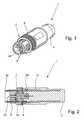
- the Fig. 1 to 3show an electrical connector 1 as part of a total in the Fig. 8 and 9 illustrated electrical connector, wherein the electrical Connector 1 for releasably connecting a cable with a in the 10 to 12 shown mating connector 2 is used.
- the electrical connector 1has a cable or - in Fig. 4 shown - veins 3 surrounding handle body 4, a total of eight contact elements 5 receiving and holding contact carrier 6 and a rotatably mounted cap screw 7 with an external thread 8.
- the electrical connector 1can be connected to the mating connector 2, that the cap screw 7 with its external thread 8 in a mating connector 2 associated outer sleeve 9, which has a corresponding internal thread 10, is screwed.
- both the external thread 8 of the cap screw 7 and the internal thread 10 of the outer sleeve 9are partially interrupted, that is, both the external thread 8 and the internal thread 10 have a plurality provided in plug or screw thread-free areas.
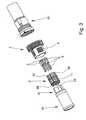
- the contact carrier 6consists of four separate contact carrier parts 61, 62, 63, 64, each having a quarter-circle-shaped base. As in particular from the Fig. 5 to 7 can be seen, in the individual contact carrier parts 61, 62, 63, 64 each two outwardly open, parallel to the longitudinal axis of the connector 1 and the contact carrier 6 extending grooves 11 are formed. The grooves 11 serve to receive a portion of the contact elements 5.
- each have two through holes 13are formed, which are arranged in the end face 12 that they directly adjoin the grooves 11, so that the wires 3 facing away from the ends 14 of the contact elements 5 protrude through the through holes 13 in the assembled state. Since the electrical connector 1 shown in the figures has a total of eight contact elements 5, thus eight grooves 11 and eight through holes 13 are formed in the contact carrier 6 in total.
- a contact element 5is thereby particularly easy in the contact carrier 6 and a contact carrier part 61 are mounted that initially the free, pin-shaped end 14 at an angle to the longitudinal axis the contact carrier part 61 is greater than zero, ie obliquely from the side through the through hole 13 is inserted ( Fig. 6a and 7a ). Only then is the contact element 5 aligned in the longitudinal direction of the contact carrier part 61 by the wires 3 facing the hollow end 15 of the contact element 5 is pivoted or pressed into the groove 11.
- the connector 1additionally has a cylindrical sleeve 19 with a formed inside the sleeve 19 cross-shaped shielding element 20 and a shielding sleeve 21.
- the cylindrical sleeve 19 with the arranged therein, integrally connected to the sleeve 19 cross-shaped Schirmungselement 20serves to receive the individual contact carrier parts 61, 62, 63, 64 with the contact elements 5 arranged therein.
- the cross-shaped shielding element 20thus the individual contact carrier parts 61, 62, 63, 64 and thus arranged in the contact carrier parts 61, 62, 63, 64 contact elements 5 are separated from each other, so that a crosstalk between one, a contact carrier member 61 associated shielded wire pair and another, a second Contact support member 62 associated shielded wire pair is largely prevented.
- the further shielding sleeve 21By arranging the further shielding sleeve 21 on the opposite side of the mating connector 2 of the electrical connector 1, which is arranged in the handle body 4 produced by molding, the individual wires 3 and the individual wire pairs are additionally shielded.
- the cross-shaped shielding element 20 and the shielding sleeve 21are arranged and formed so that they overlap in the longitudinal direction of the connector 1.
- a sealing ring and a spring ringcan be seen, in the exploded view according to Fig. 3 are omitted, since they are not essential to the invention.
- the mating contact elements 22have a central region 24, in which the outer diameter - compared to the outer diameter of the remaining regions of the mating contact elements 22 - is reduced.
- the reduction of the outer diameter of the contact elements 22 in the central region 24serves to adapt the differential longitudinal impedance of the mating contact elements 22, whereby an impedance jump in the longitudinal direction of the electrical connector should be avoided. Since the differential longitudinal impedance of the individual mating contact elements 22 depends inter alia on their outer diameter and the center distance of the mating contact elements 22 to each other, an impedance matching can be achieved by reducing the outer diameter in the central region 24 of the mating contact elements 22, without the arrangement of the individual mating contact elements 22 are changed got to.
- the contact elements 5 of the electrical connector 1 facing the end 25 of the mating contact elements 22is hollow, so that the pin-shaped ends 14 of the contact elements 5 can be inserted into the hollow ends 25 of the mating contact elements 22.
- the the contact elements 5 opposite ends 26 of the mating contact elements 22, however,are pin-shaped, so that the mating connector 2 can be connected, for example, with a circuit board.
- the mating contact carrier parts 71, 72, 73, 74each have two bores 27 extending in the longitudinal direction of the mating contact carrier parts 71, 72, 73, 74 for receiving the mating contact elements 22.
- the four mating contact carrier parts 71, 72, 73, 74are connected to one another via an integral ring 28.
- the mating connector 2also has a cross-shaped shielding element 29, by which the individual mating contact carrier parts 71, 72, 73, 74 and thus the mating contact elements 22 disposed therein are shielded from each other.
- the cross-shaped shielding element 29 of the mating connector 2 on the side facing away from the connector 1has an annular portion 30 which abuts in the mounted state on the end face of the outer sleeve 9.
- four pins 31are arranged, by means of which the mating connector 2 can be mounted on a circuit board.
- a codingis formed between the connector 1 and the mating connector 2, so that the connector 1 and the mating connector 2 can be screwed together only in a certain orientation to each other.
- the codingconsists of a coding nose 34 formed on the crossing region of the cross-shaped shielding element 20 and a corresponding coding recess 35 introduced on a mating contact carrier part 72.
- the figuresshow an embodiment of an electrical connector consisting of an electrical connector 1 and a mating connector 2, wherein the electrical connector 1 in particular provided and suitable, four shielded wire pairs on the arranged in four contact support members 61, 62, 63, 64 eight contact elements 5 releasably connect with the arranged in the mating contact carrier 23 eight mating contact elements 22 of the mating connector 2.
- the electrical connector 1in particular provided and suitable, four shielded wire pairs on the arranged in four contact support members 61, 62, 63, 64 eight contact elements 5 releasably connect with the arranged in the mating contact carrier 23 eight mating contact elements 22 of the mating connector 2.
Landscapes
- Details Of Connecting Devices For Male And Female Coupling (AREA)
Description
Translated fromGermanDie Erfindung betrifft einen elektrischen Steckverbinder zum lösbaren Verbinden eines mehradrigen Kabels mit einem Gegensteckverbinder, mit einem das Kabel bzw. die Adern des Kabels umgebenden Griffkörper, mit einem eine Mehrzahl von Kontaktelementen aufnehmenden bzw. haltenden Kontaktträger und mit einem drehbar angeordneten hülsenförmigen Gewindeteil, wobei die einzelnen Kontaktelemente elektrisch leitend mit den einzelnen Adern verbunden sind und wobei das hülsenförmige Gewindeteil mit einem korrespondierenden hülsenförmigen Gewindeteil des Gegensteckverbinders verschraubbar ist, nach dem Oberbegriff des Anspruchs 1. Ein solcher Steckverbinder ist aus der
Elektrische Steckverbindungen bestehen im wesentlichen aus zwei Teilen, dem elektrischen Steckverbinder und dem Gegensteckverbinder. Sowohl der Steckverbinder als auch der Gegensteckverbinder weisen jeweils einen Kontaktträger mit einer Mehrzahl von Kontakten auf, bei denen es sich entweder um Kontaktstifte oder um korrespondierende Kontaktbuchsen handelt. In Abhängigkeit davon, ob in dem jeweiligen Kontaktträger die Kontaktstifte oder die Kontaktbuchsen angeordnet sind, wird das zugehörige Verbindungsteil auch als Stecker oder als Buchse bezeichnet. In der Praxis ist es zumeist so, dass der Steckverbinder, dessen Kontaktträger die Kontaktstifte aufweist, d. h. der Stecker, eine Überwurfschraube mit einem Außengewinde als hülsenförmiges Gewindeteil und der Steckverbinder, in dessen Kontaktträger die Kontaktbuchsen angeordnet sind, d. h. die Buchse, eine Außenhülse mit einem Innengewinde aufweist. Werden mit der Steckverbindung zwei Kabel miteinander verbunden, so ist die Außenhülse der Buchse als eine Art Überwurfmutter ausgebildet.Electrical connectors consist essentially of two parts, the electrical connector and the mating connector. Both the connector and the mating connector each have a contact carrier with a plurality of contacts, which are either contact pins or corresponding contact sockets. Depending on whether the contact pins or the contact sockets are arranged in the respective contact carrier, the associated connecting part is also referred to as a plug or socket. In practice, it is usually the case that the connector whose contact carrier has the contact pins, ie the plug, a cap screw with an external thread as a sleeve-shaped threaded portion and the connector in the contact carrier, the contact sockets are arranged, ie the socket, an outer sleeve with a Internal thread has. If two cables are connected to one another with the plug connection, then the outer sleeve of the bushing is designed as a kind of union nut.
Derartige elektrische Steckverbindungen bzw. Steckverbinder werden als Industriestecker in der Automatisierungstechnik sowohl in Schaltschränken als auch bei Feldgeräten in unterschiedlichen Ausführungsformen eingesetzt. Weite Verbreitung haben insbesondere die Bauformen M8 und M12 mit 4, 5, 6 oder auch 8 Kontakten gefunden. Die Steckverbinder dienen zum Anschluss von Anschlusskabeln mit einer entsprechenden Anzahl an Adern, wobei die einzelnen Adern jeweils aus einem Leiter und einer den Leiter umgebenden Aderisolation bestehen und gemeinsam von einer Kabelisolation umgeben sind. Anstelle eines massiven Leiters können die Adern auch mehrere Litzen aufweisen, wobei nachfolgen - ohne Einschränkung hierauf-stets nur von Leitern die Rede ist; dies soll somit stets auch Litzen umfassen.Such electrical connectors or connectors are used as industrial plugs in automation technology both in cabinets and field devices in different embodiments. The types M8 and M12 with 4, 5, 6 or even 8 contacts have found widespread use. The connectors are used to connect connection cables with a corresponding number of cores, whereby the individual cores each consist of a conductor and a core insulation surrounding the conductor and are jointly surrounded by a cable insulation. Instead of a solid conductor, the wires can also have multiple strands, which follow - without limitation thereto-always only ladders is mentioned; this should therefore always include strands.
Elektrische Steckverbinder können entweder frei konfektionierbar oder bereits fertig verdrahtet sein, wobei dann der Kontaktträger und das Kabel in der Regel von dem Griffkörper umspritzt sind. Dabei kann auch der Griffkörper selber durch Umspritzen der Kontaktträger hergestellt werden.Electrical connectors can be either ready to assemble or ready wired, in which case the contact carrier and the cable are usually encapsulated by the handle body. In this case, the handle body itself can be made by molding the contact carrier.
Bei einem vom Verbraucher nicht frei konfektionierbaren Steckverbinder erfolgt die elektrische und mechanische Verbindung der einzelnen Adern bzw. Leiter eines Kabels mit den einzelnen Kontaktelementen insbesondere durch eine Lötverbindung oder durch eine Crimpverbindung. Bei der Crimp-Anschlusstechnik wird das abisolierte Ende einer Ader in eine entsprechende Anschlußhülse (Crimphülse) oder einen hülsenförmigen Endabschnitt des Kontaktelements axial eingeführt und anschließend durch mechanisches Zusammendrücken der Crimphülse bzw. des hülsenförmigen Endabschnitts elektrisch und mechanisch mit der Crimphülse bzw. dem Kontaktelement verbunden. Durch das in DIN EN 60352-2 genormte Crimpen erfolgt eine lötfreie elektrische Verbindung, wobei die Crimpverbindung sowohl durch Handcrimpwerkzeuge als auch mittels halb- oder vollautomatischer Crimpmaschinen hergestellt werden kann. Das Abisolieren der Adern und das Crimpen der Kontaktelemente lässt sich maschinell in einem Arbeitsgang durchführen, so dass die Crimptechnik das Löten weitgehend in den Hintergrund verdrängt hat.In the case of a connector which can not be freely assembled by the consumer, the electrical and mechanical connection of the individual wires or conductors of a cable to the individual contact elements takes place in particular by means of a solder connection or by a crimp connection. In the crimp termination technique, the stripped end of a wire is inserted axially into a corresponding ferrule (crimp barrel) or sleeve-shaped end portion of the contact element and then electrically and mechanically connected to the crimp barrel or contact element by mechanical compression of the crimp barrel or sleeve-shaped end portion. By crimping standardized in DIN EN 60352-2 a solderless electrical connection is made, wherein the crimped connection can be made both by Handcrimpwerkzeuge and by means of semi or fully automatic crimping machines. The stripping of the wires and the crimping of the contact elements can be carried out by machine in one operation, so that the crimping technique has largely superseded the soldering in the background.
Elektrische Steckverbindungen sind Schnittstellen, die elektrische Signale oder Leistungen übertragen, wobei die Steckverbindungen bzw. Steckverbinder je nach Anwendungsfall unterschiedliche Anforderungen erfühlen müssen. Bei Steckverbindern, die in der Signal- und Datentechnik eingesetzt werden, insbesondere bei solchen Steckverbindern, die innerhalb von Netzwerken und Feldbussen eingesetzt werden, müssen entsprechend der Datenübertragungsrate des jeweiligen Netzwerks bzw. Feldbusses gewisse hochfrequente Randbedingungen berücksichtigt werden, um ein einwandfreies Übertragen der Signale und Daten zu gewährleisten.Electrical connectors are interfaces that transmit electrical signals or power, the connectors or connectors need to feel different requirements depending on the application. In the case of connectors used in signal and data technology, in particular in the case of connectors which are used within networks and fieldbuses, In accordance with the data transmission rate of the respective network or field bus, certain high-frequency boundary conditions must be taken into account in order to ensure a faultless transmission of the signals and data.
Werden Steckverbinder bzw. Steckverbindungen für die Signal- und Datentechnik nicht nur in Bürogebäuden sondern auch im rauen industriellen Umfeld eingesetzt, so müssen die Steckverbinder bzw. Steckverbindungen entsprechend robuster ausgebildet sein und eine möglichst hohe Schutzart, vorzugsweise IP67 aufweisen. Aus diesem Grund sind handelsübliche RJ45-Stecker, wie sie aus dem Bürokommunikationsbereich bekannt sind, im industriellen Bereich nur eingeschränkt einsetzbar. Daher sind Schutzgehäuse, so genannte Tüllengehäuse, entwickelt worden, die ein bereits mit einem Kabel verbundenen RJ45-Stecker aufnehmen können und dadurch den Stecker gegen äußere Einflüsse und Beschädigungen schützen. Ein entsprechendes Schutzgehäuse ist beispielsweise aus der
Um die im industriellen Bereich weit verbreiteten Steckverbinder der Bauform M12, die eine ausreichende mechanische Robustheit und Schutzklasse aufweisen, auch im Bereich der Signal- und Datentechnik, insbesondere bei Netzwerken und Feldbussen - und hier insbesondere auch für Ethernet-Anwendungen - einsetzen zu können, muss deren innerer Aufbau dahingehend modifiziert werden, dass die Anforderungen hinsichtlich der Datenübertragung erfüllt werden können. Insbesondere bei höheren Übertragungsraten sind dabei Steckverbinder mit einer größeren Anzahl an Kontakten, insbesondere mit acht Kontakten, erforderlich. Vergrößert sich die Anzahl der Kontakte, so führt dies - bei ansonsten gleich bleibendem Durchmesser des Steckverbinders - aufgrund der geringen Abmessungen zu einer aufwendigeren Montage des Steckverbinders sowie zu einem aufwendigeren Anschluss der einzelnen Adern an die einzelnen Kontaktelemente.In order to be able to use the M12 connectors, which are widely used in the industrial sector, and which have sufficient mechanical robustness and protection class, also in the area of signal and data technology, in particular for networks and field buses - and in particular also for Ethernet applications their internal structure are modified so that the requirements for data transmission can be met. In particular, at higher transmission rates while connectors with a larger number of contacts, especially with eight contacts required. Increases the number of contacts, it leads - with otherwise constant diameter of the connector - due to the small dimensions to a more complex installation of the connector and a more complex connection of the individual wires to the individual contact elements.
Der vorliegenden Erfindung liegt daher die Aufgabe zugrunde, einen eingangs beschriebenen elektrischen Steckverbinder dahingehend weiterzuentwickeln, dass die Montage des Steckverbinders, insbesondere die Montage der Kontaktelemente im Kontaktträger einfacher möglich ist. Darüber hinaus liegt der Erfindung die Aufgabe zugrunde, eine elektrische Steckverbindung anzugeben, die bei möglichst kompaktem Aufbau besonders gut für die Signal- und Datenübertragung im rauen industrielen Umfeld geeignet ist.The present invention is therefore the object of further developing an electrical connector described above to the effect that the assembly of the connector, in particular the mounting of the contact elements in the contact carrier is easier. In addition, the invention has for its object to provide an electrical connector that is particularly well suited for the signal and data transmission in the harsh industrial environment with a compact design possible.
Die zuvor genannte Aufgabe ist durch einen elektrisches Steckverbinder nach Anspruch 1 gelöst.The above object is achieved by an electrical connector according to
Durch die erfindungsgemäße Ausgestaltung des Kontaktträgers wird das Einführen der Kontaktelemente in den Kontaktträger wesentlich erleichtert. Durch die Ausbildung der nach außen offenen Nuten anstelle der ansonsten bei Kontaktträgern ausgebildeten, sich über die gesamte Länge des Kontaktträgers erstreckenden Durchgangslöcher, kann ein Kontaktelement mit seinem der angeschlossenen Ader abgewandten Ende einfach durch das Durchgangsloch in der Stirnseite des Kontaktträgers durchgesteckt werden, wobei das Kontaktelement beim Durchstecken durch das Durchgangsloch einen Winkel zur Längsachse des Kontaktträgers größer Null aufweisen kann. Das freie Ende des Kontaktelements kann somit "schräg von der Seite" durch das Durchgangsloch durchgesteckt werden und erst danach in die korrespondierende Nut eingeschwenkt werden.The inventive design of the contact carrier, the insertion of the contact elements in the contact carrier is much easier. By forming the outwardly open grooves instead of the otherwise formed in contact carriers, extending over the entire length of the contact carrier through holes, a contact element with its end facing away from the connected conductor can be simply inserted through the through hole in the end face of the contact carrier, wherein the contact element when passing through the through hole may have an angle to the longitudinal axis of the contact carrier greater than zero. The free end of the contact element can thus be pushed "obliquely from the side" through the through hole and only then be pivoted into the corresponding groove.
Diese Vorgehensweise vereinfacht das Einführen der bereits mit den Adern verbundenen Kontaktelemente in den Kontaktträger erheblich. Zum einen müssen die freien Enden der Kontaktelemente nur durch die in der Stirnseite des Kontaktträgers ausgebildeten Durchgangslöcher, deren Länge wesentlich geringer ist als die Gesamtlänge des Kontaktträgers, durchgesteckt werden. Zum anderen erleichtert die Möglichkeit des Einsteckens der Kontaktelemente "schräg von der Seite" die Montage auch einer Mehrzahl von Kontaktelementen bei einem kompakten Steckverbinder.This procedure simplifies the insertion of the already connected to the wires contact elements in the contact carrier considerably. On the one hand, the free ends of the contact elements need only be pushed through the through holes formed in the end face of the contact carrier, whose length is substantially less than the total length of the contact carrier. On the other hand, the possibility of inserting the contact elements "obliquely from the side" facilitates the assembly of a plurality of contact elements in a compact connector.
Gemäß der Erfindung sind die Durchgangslöcher in der Stirnseite des Kontaktträgers trichterförmig ausgebildet, wobei sich der Innendurchmesser der Durchgangslöcher von der den Nuten zugewandten Seite zur dem Gegensteckverbinder zugewandten Seite vergrößert. Die trichterförmige Ausbildung der Durchgangslöcher erleichtert die Schrägstellung der Kontaktelemente beim Einstecken in die Durchgangslöcher. Das Durchstecken und Einschwenken der Kontaktelemente wird dabei weiter erleichtert, wenn die Trichterform der Durchgangslöcher konzentrisch zur bevorzugten Einsteckrichtung der Kontaktelemente ausgerichtet ist. Zusätzlich können die Durchgangslöcher so ausgebildet sein, dass sie an ihrer schmalsten Stelle einen geringfügig größeren Durchmesser als die durchzusteckenden Enden der Kontaktelemente aufweisen.According to the invention, the through-holes in the end face of the contact carrier are funnel-shaped, with the inner diameter of the through-holes increasing from the side facing the grooves to the side facing the mating connector. The funnel-shaped formation of the through holes facilitates the inclination of the contact elements when inserted into the through holes. The insertion and pivoting of the contact elements is further facilitated if the funnel shape of the through holes is aligned concentrically with the preferred insertion direction of the contact elements. In addition, the through holes may be formed so that they have at their narrowest point a slightly larger diameter than the ends of the contact elements durchzusteckenden.
Die einzelnen Kontaktelemente sind bei dem erfindungsgemäßen elektrischen Steckverbinder nur in einem relativ geringen Bereich ihrer Gesamtlänge in einem Durchgangsloch geführt, während das freie Ende aus dem Durchgangsloch herausragt und das den Adern zugewandte Ende im montierten Zustand in der nach außen offenen Nut angeordnet ist. Dadurch ist die axiale Ausrichtung der Kontaktelemente weniger gut gesichert als bei herkömmlichen Kontaktträgern, bei denen die Länge der Durchgangslöcher der Länge des Kontaktträgers entspricht. Um die axiale Ausrichtung der Kontaktelemente in dem Kontaktträger besser zu gewährleisten, ist daher vorzugsweise vorgesehen, dass die Durchgangslöcher auf der dem Gegensteckverbinder zugewandten Stirnseite des Kontaktträgers jeweils von einem Kragen umgeben sind. Damit der Kragen das Einstecken des freien Endes eines Kontaktelements "schräg von der Seite" nicht behindert, weisen die Kragen auf der der Mittelachse des Steckverbinders zugewandten Seite jeweils eine Unterbrechung auf.The individual contact elements are guided in the electrical connector according to the invention only in a relatively small portion of their total length in a through hole, while the free end protrudes from the through hole and the wires facing the end is arranged in the mounted state in the outwardly open groove. As a result, the axial alignment of the contact elements is less well secured than in conventional contact carriers, in which the length of the through holes corresponds to the length of the contact carrier. In order to better ensure the axial alignment of the contact elements in the contact carrier, it is therefore preferably provided that the through-holes are each surrounded by a collar on the front side of the contact carrier facing the mating connector. Thus, the collar does not interfere with the insertion of the free end of a contact element "obliquely from the side", the collar on the side facing the central axis of the connector side each have an interruption.
Um die axiale Ausrichtung der Kontaktelemente in dem Kontaktträger besser zu gewährleisten, und um ein ungewolltes Herausschwenken der Kontaktelemente aus den Nuten zu verhindern, ist in den einzelnen Nuten vorzugsweise eine Einschnürung ausgebildet, in die die Kontaktelemente beim Einschwenken in die Nuten einrasten können. Weisen die Kontaktelemente korrespondierend zu den Nuten einen Abschnitt mit einem vergrößerten Durchmesser auf, beispielsweise ein den Adern zugewandtes hohles Ende, so kann auf einfache Art und Weise eine Verrastung zwischen der in den Nuten ausgebildeten Einschnürung und dem Abschnitt mit vergrößertem Durchmesser realisiert werden.In order to better ensure the axial alignment of the contact elements in the contact carrier, and to prevent unwanted swinging out of the contact elements from the grooves, a constriction is preferably formed in the individual grooves, in which the contact elements can engage in the grooves during pivoting. If the contact elements have a section with an enlarged diameter corresponding to the grooves, for example a hollow end facing the wires, a latching between the constriction formed in the grooves and the section with increased diameter can be realized in a simple manner.
Die zuvor beschriebene erfindungsgemäße Ausgestaltung des Kontaktträgers kann grundsätzlich bei allen Rundsteckverbindern eingesetzt werden. Besonders vorteilhaft ist die erfindungsgemäße Ausgestaltung des Kontaktträgers jedoch bei solchen Steckverbindern, die eine größere Anzahl an Kontaktelementen aufweisen, insbesondere bei Steckverbindern, die zum Anschluss von Kabeln mit vier Adernpaaren dienen und somit acht Kontaktelemente aufweisen. Bei einem derartigen Steckverbinder ist gemäß einer weiteren vorteilhaften Ausgestaltung der Erfindung vorgesehen, dass der Kontaktträger aus vier Kontaktträgerteilen besteht, die jeweils eine viertelkreisförmige Grundfläche aufweisen. Ist der Steckverbinder zum Anschluss von vier Adernpaaren vorgesehen, so sind in jedem Kontaktträgerteil zwei Nuten und in der dem Gegensteckverbinder zugewandten Stirnseite jedes Kontaktträgerteils korrespondierend zwei Durchgangslöcher ausgebildet. Die beiden Adern eines Adernpaares, welche vorzugsweise miteinander verdrillt sind, werden somit mit zwei Kontaktelementen verbunden, die nach der Montage in einem Kontaktträgerteil angeordnet sind.The above-described embodiment of the contact carrier according to the invention can in principle be used in all circular connectors. However, the inventive design of the contact carrier is particularly advantageous in such connectors, which have a larger number of contact elements, in particular for connectors that are used to connect cables with four wire pairs and thus have eight contact elements. In such a connector is provided according to a further advantageous embodiment of the invention, that the contact carrier consists of four contact carrier parts, each having a quarter-circle-shaped base. If the connector is provided for connecting four pairs of wires, then two grooves are formed in each contact carrier part and two through holes are correspondingly formed in the end side of each contact carrier part facing the mating connector. The two wires of a pair of wires, which are preferably twisted together, are thus connected to two contact elements, which are arranged after assembly in a contact carrier part.
Dient der elektrische Steckverbinder zum Anschluss eines Kabels der Signal- und Datentechnik, insbesondere zum Anschluss eines Kabels, bei dem die verdrillten Adernpaare, mit einem metallischen Schirm umgeben sind (FTP = Foiled Twisted Pair bzw. PiMF = Paar in Metallfolie), so weist der elektrische Steckverbinder gemäß einer weiteren vorteilhaften Ausgestaltung zusätzlich eine zylinderförmige Hülse mit einem sich in Längsrichtung der Hülse erstreckenden, innerhalb der Hülse angeordneten kreuzförmigen Schirmungselement auf. Die vier Kontaktträgerteile sind dann derart innerhalb der zylinderförmigen Hülse angeordnet, dass die einzelnen Kontaktträgerteile durch die Arme des kreuzförmigen Schirmungselements voneinander getrennt sind. Hierdurch kann ein Übersprechen von einem Adernpaar auf ein anderes Adernpaar weitestgehend unterbunden werden, wozu die Hülse und das Schirmungselement vorzugsweise aus Metall bestehen. Zur vereinfachten Montage des elektrischen Steckverbinders sind dabei die Hülse und das Schirmungselement vorzugsweise einstückig ausgebildet.Serves the electrical connector for connecting a cable signal and data technology, in particular for connecting a cable in which the twisted wire pairs, with a metallic shield are surrounded (FTP = Foiled Twisted Pair or PiMF = pair in metal foil), so has the electrical connector according to a further advantageous embodiment, in addition a cylindrical sleeve with a longitudinally extending sleeve, arranged within the sleeve cross-shaped shielding element. The four contact carrier parts are then arranged inside the cylindrical sleeve such that the individual contact carrier parts are separated from one another by the arms of the cross-shaped shielding element. As a result, a crosstalk from one pair of wires to another pair of wires can be largely prevented, for which purpose the sleeve and the shielding element are preferably made of metal. For simplified installation of the electrical connector while the sleeve and the shielding element are preferably formed integrally.
Gemäß einer bevorzugten Ausgestaltung ragt das kreuzförmige Schirmungselement auf der dem Kabel zugewandten Seite aus der Hülse heraus, so dass an dem herausragenden Ende des Schirmungselements die metallischen Schirme der einzelnen verdrillten Adernpaare (PiMF) befestigt werden können, wodurch die Abschirmung zwischen den einzelnen Adernpaaren weiter verbessert und somit die Wahrscheinlichkeit eines Übersprechens von einem Adernpaar auf ein anderes Adernpaars weiter verringert wird.According to a preferred embodiment, the cross-shaped shielding element protrudes on the side facing the cable out of the sleeve, so that the metallic shields of the individual twisted pairs of wires (PiMF) can be attached to the protruding end of the Schirmungselements, whereby the shield between the individual pairs of wires further improved and thus further reducing the likelihood of crosstalk from one wire pair to another wire pair.
Um die Positionierung der einzelnen Kontaktträgerteile innerhalb der Hülse weiter zu erleichtern, ist am Innenumfang der Hülse vorzugsweise ein Anschlag für die Kontaktträgerteile ausgebildet. Nach dem Einstecken der Kontaktelemente in die einzelnen Kontaktträgerteile können diese somit einfach in die durch die Hülse und das kreuzförmige Schirmungselement gebildeten Kammern eingesteckt werden.In order to further facilitate the positioning of the individual contact carrier parts within the sleeve, a stop for the contact carrier parts is preferably formed on the inner circumference of the sleeve. After inserting the contact elements in the individual contact carrier parts, these can thus be easily inserted into the chambers formed by the sleeve and the cross-shaped shielding element.
Bei einer electrischen Steckverbindung bestehend aus einem Steckverbinder nach Anspruch 1 und einem Gegensteckverbinder, wobei der Steckverbinder einen ein Kabel umschließenden Griffkörper, einen eine Mehrzahl von Kontaktelementen aufnehmenden bzw. haltenden Kontaktträger und eine drehbar angeordnete Überwurfschraube mit einem Außengewinde und der Gegensteckverbinder eine Außenhülse mit einem zum Außengewinde der Überwurfschraube korrespondierenden Innengewinde und einen eine Mehrzahl von Gegenkontaktelementen aufnehmenden bzw. haltenden Gegenkontaktträger aufweist, wird die Eignung der Steckverbindung für die Signal- und Datenübertragung, insbesondere für Ethernet-Anwendungen dadurch auf einfache Art und Weise verbessert, dass die Gegenkontaktelemente des Gegensteckverbinders einen sich in axialer Richtung erstreckenden Bereich aufweisen, in dem der Außendurchmesser zur Impedanzanpassung verringert ist.In an electrical connector consisting of a connector according to
Um eine fehlerfreie Datenübertragung bei Steckverbindungen, insbesondere bei solchen, die bei Busverbindungen oder Netzwerken mit hohen Datenübertragungsraten eingesetzt werden, gewährleisten zu können, müssen bestimmte hochfrequente Randbedingungen berücksichtigt werden. Neben dem möglichst geringen Übersprechen zwischen einzelnen Adernpaaren ist dabei die Reduzierung der Rückflussdämpfung von besonderer Bedeutung. Die Rückflussdämpfung (Return Loss) wird im Wesentlichen durch die Homogenität des Wellenwiderstands bestimmt. Tritt in Ausbreitungsrichturig der elektromagnetischen Welle ein Impedanzsprung auf, so führt dies zu Reflektionen, die sich mit den zu übertragenden Nutzsignalen überlagern können, so dass es durch Interferenzen zur teilweisen Auslöschung des zu übertragenden Nutzsignals kommen kann.In order to ensure error-free data transmission in plug-in connections, in particular in those used in bus connections or networks with high data transmission rates, certain high-frequency boundary conditions must be taken into account. In addition to the lowest possible crosstalk between individual pairs of wires while reducing the return loss is of particular importance. The return loss (return loss) is essentially determined by the homogeneity of the characteristic impedance. Occurs in propagation direction of the electromagnetic wave an impedance jump, this leads to reflections that can be superimposed with the useful signals to be transmitted, so that it may be due to interference to the partial extinction of the useful signal to be transmitted.
Da bei einer elektrischen Steckverbindung, die im industriellen Bereich eingesetzt werden soll, neben den hochfrequenten Randbedingungen auch andere Anforderungen, wie eine möglichst hohe Schutzklasse, eine ausreichende Kompaktheit bei gleichzeitig hoher mechanischer Stabilität und eine möglichst einfache Herstellbarkeit berücksichtigt werden müssen, kann es vorkommen, dass die Kontaktelemente des Steckverbinders in der Praxis eine andere differenzielle Längsimpedanz aufweisen als die Gegenkontaktelemente des Gegensteckverbinders.Since in an electrical connector to be used in the industrial sector, in addition to the high-frequency boundary conditions other requirements, such as the highest possible protection class, sufficient compactness and high mechanical stability and ease of manufacture must be considered, it may happen that the contact elements of the connector in practice have a different differential longitudinal impedance than the mating contact elements of the mating connector.
Ein Unterschied zwischen der differenziellen Längsimpe-danz der Kontaktelemente des Steckverbinders und der differenziellen Längsimpedanz der Gegenkontaktelemente des Gegensteckverbinders kann dadurch weitestgehend reduziert werden, dass die Gegenkontaktelemente einen sich in axialer Richtung erstreckenden Bereich aufweisen, in dem der Außendurchmesser - im Vergleich zum Außendurchmesser in den anderen Bereichen des Gegenkontaktelements - verringert ist.A difference between the differential longitudinal impedance The contact elements of the connector and the differential longitudinal impedance of the mating contact elements of the mating connector can be largely reduced, that the mating contact elements have a region extending in the axial direction, in which the outer diameter - compared to the outer diameter in the other areas of the mating contact element - is reduced.
Dadurch ist eine Impedanzanpassung der Gegenkontaktelemente an die Kontaktelemente möglich, ohne dass andere Parameter der Steckverbindung, beispielsweise die elektrische Leitfähigkeit der Kontaktelemente und der Gegenkontaktelemente oder der Anstand der Kontaktelemente bzw. der Gegenkontaktelemente zueinander verändert werden müssen. Da die differenzielle Längsimpedanz vom Verhältnis des Durchmessers eines Kontaktelements bzw. Gegenkontaktelements zum Mittenabstand zu benachbarten Kontaktelemente bzw. Gegenkontaktelemente abhängt, kann die differenzielle Längsimpedanz der Gegenkontaktelemente durch Veränderung des Durchmessers der Gegenkontaktelemente so angepasst werden, dass die differenzielle Längsimpedanz der Gegenkontaktelemente näherungsweise einem vorgegebenen Sollwert, beispielsweise 100 Ohm entspricht.Thereby, an impedance matching of the mating contact elements to the contact elements is possible without other parameters of the connector, for example, the electrical conductivity of the contact elements and the mating contact elements or the decency of the contact elements and the mating contact elements to each other must be changed. Since the differential longitudinal impedance depends on the ratio of the diameter of a contact element or mating contact element to the center distance to adjacent contact elements or mating contact elements, the differential longitudinal impedance of the mating contact elements by changing the diameter of the mating contact elements can be adjusted so that the differential longitudinal impedance of the mating contact elements approximately a predetermined setpoint, for example, corresponds to 100 ohms.
Gemäß einer Ausgestaltung der elektrischen Steckverbindung ist das den Gegenkontaktelementen zugewandte Ende der Kontaktelemente stiftförmig und das den Kontaktelementen zugewandte Ende der Gegenkontaktelemente hohl ausgebildet, so dass die stiftförmigen Enden der Kontaktelemente in die hohlen Enden der Gegenkontaktelemente eingesteckt werden können. Sind die den Kontaktelementen abgewandten Enden der Gegenkontaktelemente stiftförmig ausgebildet, so können die Gegenkontaktelemente geräteseitig einfach mit einer Leiterplatte, beispielsweise im Wellenlötverfahren verbunden werden.According to one embodiment of the electrical plug connection, the counter contact elements facing the end of the contact elements pin-shaped and the contact elements facing the end of the mating contact elements is hollow, so that the pin-shaped ends of the contact elements can be inserted into the hollow ends of the mating contact elements. If the ends of the mating contact elements facing away from the contact elements are pin-shaped, the mating contact elements can simply be connected to a circuit board on the device side, for example by wave soldering.
Um bei der elektrischen Steckverbindung auch im Gegenstecker ein Übersprechen zwischen einzelnen Adern oder einzelnen Adernpaaren zu unterbinden, besteht der Gegenkontaktträger des Gegensteckverbinders gemäß einer Ausgestaltung aus vier Gegenkontaktträgerteilen, die jeweils eine viertelkreisförmige Grundfläche aufweisen, wobei in jedem Gegenkontaktträgerteil mindestens eine sich in Längsrichtung erstreckende Bohrung zur Aufnahme eines Gegenkontaktelements angeordnet ist. Bei einer derartigen Ausgestaltung des Gegenkontaktträgers sind die vier Gegenkontaktträgerteile durch ein innerhalb der Außenhülse angeordnetes, sich in Längsrichtung der Außenhülse bzw. des Gegenkontaktträgers erstreckendes kreuzförmiges Schirmungselement gegeneinander abgeschirmt. Die vier Kontaktträgerteile sind dabei an ihrem Außenumfang bereichsweise miteinander verbunden, so dass das kreuzförmige Schirmungselement im montierten Zustand des Gegensteckverbinders in entsprechenden Nuten, die zwischen den einzelnen Gegenkontaktträgerteilen ausgebildet sind, angeordnet ist.In order to prevent crosstalk between individual wires or individual wire pairs in the mating connector in the mating connector, the mating contact carrier of the mating connector according to an embodiment of four mating contact carrier parts, each having a quarter-circle base, wherein in each mating contact carrier part at least one longitudinally extending bore for Recording a mating contact element is arranged. In such an embodiment of the mating contact carrier, the four mating contact carrier parts are arranged by an inside of the outer sleeve, Shielded in the longitudinal direction of the outer sleeve and the mating contact carrier extending cross-shaped shielding element against each other. The four contact carrier parts are partially connected to each other at their outer periphery, so that the cross-shaped shielding element in the assembled state of the mating connector in corresponding grooves formed between the individual mating contact carrier parts, is arranged.
Gemäß einer weiteren Ausgestaltung der elektrischen Steckverbindung, bei der sowohl der Gegensteckverbinder als auch der Steckverbinder ein kreuzförmiges Schirmungselement aufweist, haben die einzelnen Arme des kreuzförmigen Schirmungselements des Steckverbinders auf der dem Gegensteckverbinder zugewandten Seite jeweils eine sich in Längsrichtung des Steckverbinders erstreckende Verlängerung und die einzelnen Arme des kreuzförmigen Schirmungselements des Gegensteckverbinders auf der dem Steckverbinder zugewandten Seite jeweils eine sich in Längsrichtung des Gegensteckverbinders erstreckende korrespondierende Gegenverlängerung. Die Verlängerungen und die Gegenverlängerungen sind so angeordnet und ausgebildet, dass sie sich in axialer Richtung überlappen, wenn der Steckverbinder und der Gegensteckverbinder miteinander verbunden sind. Durch das axiale "Überlappen" des kreuzförmigen Schirmungselements des Steckverbinders mit dem kreuzförmigen Schirmungselement des Gegensteckverbinders wird ein Übersprechen von einem Adernpaar auf ein anderes Adernpaar über die gesamte Länge der elektrischen Steckverbindung effektiv unterdrückt.According to a further embodiment of the electrical connector, in which both the mating connector and the connector has a cross-shaped shielding element, the individual arms of the cross-shaped Schirmungselements of the connector on the mating connector side facing each extending in the longitudinal direction of the connector extension and the individual arms the cross-shaped shielding element of the mating connector on the side facing the connector in each case one extending in the longitudinal direction of the mating connector corresponding counter-extension. The extensions and the counter-extensions are arranged and formed so that they overlap in the axial direction when the connector and the mating connector are connected together. By the axial "overlapping" of the cross-shaped shielding element of the connector with the cross-shaped shielding element of the mating connector crosstalk from one pair of wires to another pair of wires over the entire length of the electrical connector is effectively suppressed.
Neben dem eingangs beschriebenen elektrischen Steckverbinder betrifft die vorliegende Erfindung gemäß Anspruch 8 auch ein Verfahren zum Anschließen der Adern eines mehradrigen Kabels an einen elektrischen Steckverbinder, wobei der elektrische Steckver-binder - wie zuvor beschrieben - einen Griffkörper, einen Kontaktträger zur Aufnahme einer Mehrzahl von Kontaktelementen und ein drehbar angeordnetes hülsenartiges Gewindeteil aufweist. Der Kontaktträger des Steckverbinders weist dabei eine der Anzahl der Kontaktelemente entsprechende Anzahl an nach außen offenen, parallel zur Längsachse des Kontaktträgers verlaufenden Nuten und in der den Adern abgewandten Stirnseite des Kontaktträgers, angrenzend an die Nuten, eine entsprechende Anzahl an Durchgangslöchern auf. Bei dem Verfahren ist das Anschließen der einzelnen abisolierten Adern durch folgende Schritte gekennzeichnet:
- Verbinden der einzelnen abisolierten Enden der Adern mit den zugewandten Enden der einzelnen Kontaktelemente,
- Durchstecken der den Adern abgewandten Enden der Kontaktelemente durch die Durchgangslöcher in der Stirnseite des Kontaktträgers, wobei die Kontaktelemente beim Durchstecken einen Winkel zur Längsachse des Kontaktträgers größer Null aufweisen, und
- Einschwenken der Kontaktelemente in die Nuten im Kontaktträger, so dass die Kontaktelemente und mit ihnen die Adern parallel zur Längsachse des Kontaktträgers verlaufen.
- Connecting the individual stripped ends of the wires to the facing ends of the individual contact elements,
- Passing through the through holes in the end face of the contact carrier, the contact elements facing away from the wires of the contact elements, wherein the contact elements have an angle to the longitudinal axis of the contact carrier greater than zero when passing through, and
- Swiveling the contact elements in the grooves in the contact carrier, so that the contact elements and with them the wires are parallel to the longitudinal axis of the contact carrier.
Vorteilhafterweise ist das erfindungsgemäße Verfahren bei einem elektrischen Steckverbinder, bei dem das den Adern zugewandte Ende der Kontaktelemente hohl ausgebildet ist, dadurch maschinell besonders einfach durchführbar, dass die einzelnen abisolierten Enden der Adern in die hohlen Enden der Kontaktelemente eingesteckt und durch mechanisches Zusammendrücken (Crimpen) der Enden der einzelnen Adern mit den einzelnen Kontaktelementen elektrisch leitend verbunden werden. Dazu kann ein Kontaktelement mit in das hohle Ende eingeführter Ader in die Aufnahme einer entsprechenden Pressbacke eingelegt werden und anschließend durch Niederdrücken einer Gegenbacke das Kontaktelement im Bereich der eingeführten Ader zusammengedrückt werden, wodurch das abisolierte Ende der Ader mit dem Kontaktelement elektrisch und mechanisch fest verbunden wird.Advantageously, the inventive method is in an electrical connector in which the wires facing the end of the contact elements is hollow, characterized by machine particularly easy to carry out that the individual stripped ends of the wires inserted into the hollow ends of the contact elements and by mechanical compression (crimping) the ends of the individual wires are electrically connected to the individual contact elements. For this purpose, a contact element inserted into the hollow end of the core can be inserted into the receptacle of a corresponding pressing jaw and then pressed together by depressing a counter-jaw, the contact element in the region of the inserted wire, whereby the stripped end of the wire is electrically and mechanically firmly connected to the contact element ,
Sind die einzelnen Kontaktelemente mit dem damit elektrisch leitend verbundenen Adern in den Kontaktträger oder in einzelne Kontaktträgerteile eingesetzt, so wird der Kontaktträger bzw. die Kontaktträgerteile vorzugsweise in eine zylinderförmige Hülse mit einem innerhalb der Hülse angeordneten, sich in Längsrichtung der Hülse erstreckenden kreuzförmigen Schirmungselement eingeschoben. Danach wird das hülsenartige Gewindeteil auf die Hülse aufgeschoben und anschließend die mit den Kontaktelementen verbundenen Adern und das Kontaktträgerteil bzw. die Kontaktträgerteile zur Herstellung eines Griffkörpers umspritzt.If the individual contact elements with the wires thus connected electrically conductively inserted into the contact carrier or in individual contact carrier parts, the contact carrier or the contact carrier parts is preferably inserted into a cylindrical sleeve with a disposed within the sleeve, extending in the longitudinal direction of the sleeve cross-shaped shielding element. Thereafter, the sleeve-like threaded portion is pushed onto the sleeve and then encapsulated with the contact elements connected to the wires and the contact carrier part or the contact carrier parts for producing a handle body.
Im Einzelnen gibt es nun eine Vielzahl von Möglichkeiten, den erfindungsgemäßen elektrischen Steckverbinder und das erfindungsgemäße Verfahren auszugestalten und weiterzubilden. Dazu wird verwiesen sowohl auf die nachgeordneten Patentansprüche als auch auf die nachfolgende Beschreibung eines bevorzugten Ausführungsbeispiels in Verbindung mit der Zeichnung. In der Zeichnung zeigen
- Fig. 1
- eine perspektivische Darstellung eines erfindungsgemäßen elektrischen Steckverbinders,
- Fig. 2
- den elektrischen Steckverbinder gemäß
Fig. 1 , in Schnittdarstellung, - Fig. 3
- eine Exlosionsdarstellung der wesentlichen Bauteile des elektrischen Steckverbinders gemäß
Fig. 1 , - Fig. 4
- eine vergrößerte Darstellung eines Teils des Steckverbinders, mit angeschlossenen Adern,
- Fig. 5
- eine vergrößerte Darstellung eines Kontaktträgerteils des elektrischen Steckverbinders,
- Fig. 6
- zwei Darstellungen eines Kontaktträgerteils mit zwei Kontaktelementen,
- Fig. 7
- zwei Schnittdarstellungen des Kontaktträgerteils gemäß
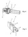
Fig. 6 , - Fig. 8
- eine perspektivische Darstellung einer elektrischen Steckverbindung, bestehend aus einem Steckverbinder und einem Gegensteckverbinder,
- Fig. 9
- die elektrische Steckverbindung gemäß
Fig. 8 , in Schnittdarstellung, - Fig. 10
- eine perspektivische Darstellung des Gegensteckverbinders der elektrischen Steckverbindung,
- Fig. 11
- den Gegensteckverbinder gemäß
Fig. 10 , in Schnittdarstellung, - Fig. 12
- eine Explosionsdarstellung der wesentlichen Bauteile des Gegensteckverbinders, und
- Fig. 13
- eine vergrößerte Darstellung eines Gegenkontaktelements des Gegensteckverbinders.
- Fig. 1
- a perspective view of an electrical connector according to the invention,
- Fig. 2
- the electrical connector according to
Fig. 1 , in section, - Fig. 3
- a Exlosionsdarstellung the essential components of the electrical connector according to
Fig. 1 . - Fig. 4
- an enlarged view of a part of the connector, with connected wires,
- Fig. 5
- an enlarged view of a contact carrier part of the electrical connector,
- Fig. 6
- two illustrations of a contact carrier part with two contact elements,
- Fig. 7
- two sectional views of the contact carrier part according to
Fig. 6 . - Fig. 8
- a perspective view of an electrical connector, consisting of a connector and a mating connector,
- Fig. 9
- the electrical connector according to
Fig. 8 , in section, - Fig. 10
- a perspective view of the mating connector of the electrical connector,
- Fig. 11
- the mating connector according to
Fig. 10 , in section, - Fig. 12
- an exploded view of the essential components of the mating connector, and
- Fig. 13
- an enlarged view of a mating contact element of the mating connector.
Die
Wie aus den
Bei der in den Figuren dargestellten bevorzugten Ausgestaltung des erfindungsgemäßen elektrischen Steckverbinders 1 besteht der Kontaktträger 6 aus vier separaten Kontaktträgerteilen 61, 62, 63, 64, die jeweils eine viertelkreisförmige Grundfläche aufweisen. Wie insbesondere aus den
Wie insbesondere aus den jeweils beiden Darstellungen in den
Aus den
Aus der Explosionsdarstellung des elektrischen Steckverbinders 1 gemäß
Durch die Anordnung der weiteren Schirmungshülse 21 auf der dem Gegensteckverbinder 2 abgewandten Seite des elektrischen Steckverbinders 1, die in dem durch Umspritzen hergestellten Griffkörper 4 angeordnet ist, sind die einzelnen Adern 3 bzw. die einzelnen Adernpaare zusätzlich abgeschirmt. Aus
Aus der Darstellung des Gegensteckverbinders 2 in den
Aus den
Insbesondere aus den
Wie insbesondere aus den
Ebenso wie der elektrische Steckverbinder 1 weist auch der Gegensteckverbinder 2 ein kreuzförmiges Schirmungselement 29 auf, durch das die einzelnen Gegenkontaktträgerteile 71, 72, 73, 74 und damit die darin angeordneten Gegenkontaktelemente 22 gegeneinander abgeschirmt werden. Anstelle einer Hülse 19 weist das kreuzförmige Schirmungselement 29 des Gegensteckverbinders 2 auf der dem Steckverbinder 1 abgewandten Seite einen ringförmigen Abschnitt 30 auf, der im montierten Zustand an der Stirnseite der Außenhülse 9 anliegt. An dem ringförmigen Abschnitt 30 sind vier Stifte 31 angeordnet, mittels derer der Gegensteckverbinder 2 auf einer Leiterplatte montiert werden kann.Like the
Aus den Schnittdarstellungen gemäß den
Um eine richtige Zuordnung der einzelnen Kontaktelemente 5 zu den einzelnen Gegenkontaktelementen 22 zu gewährleisten, ist zwischen dem Steckverbinder 1 und dem Gegensteckverbinder 2 eine Kodierung ausgebildet, so dass der Steckverbinder 1 und der Gegensteckverbinder 2 nur in einer bestimmten Orientierung zueinander miteinander verschraubt werden können. Die Kodierung besteht dabei aus einer am Kreuzungsbereich des kreuzförmigen Schirmungselements 20 ausgebildeten Kodiernase 34 und einer an einem Gegenkontaktträgerteil 72 eingebrachten korrespondierenden Kodierausnehmung 35.In order to ensure a correct assignment of the
Die Figuren zeigen eine Ausgestaltung einer elektrischen Steckverbindung, bestehend aus einem elektrischen Steckverbinder 1 und einem Gegensteckverbinder 2, wobei der elektrische Steckverbinder 1 insbesondere dafür vorgesehen und geeignet ist, vier geschirmte Adernpaare über die in vier Kontaktträgerteilen 61, 62, 63, 64 angeordneten acht Kontaktelemente 5 mit den im Gegenkontaktträger 23 angeordneten acht Gegenkontaktelementen 22 des Gegensteckverbinders 2 lösbar zu verbinden. Durch die robuste und kompakte Ausbildung des Steckverbinders 1 und des Gegensteckverbinders 2 sowie durch die Anordnung und Ausbildung der kreuzförmigen Schirmungselemente 20 und 29, welche vorzugsweise aus Metall bestehen, wird eine Steckverbindung zur Verfügung gestellt, die für Ethernet-Anwendungen im rauen industriellen Umfeld besonders gut geeignet ist. Mit der beschriebenen und dargestellten Steckverbindung werden insbesondere die Anforderungen gemäß Cat6a erreicht, so dass die Steckverbindung auch für 10 Gigabit-Ethernet und andere Netzwerk-Protokolle geeignet ist.The figures show an embodiment of an electrical connector consisting of an
Claims (12)
- Electrical connector for detachable connection of a multicore cable to a mating connector (2), with a handle body (4) which surrounds the cable and the cores (3) of the cable, with a contact carrier (6) which holds or accommodates a plurality of contact elements (5) and with a pivotally arranged sleeve-shaped threaded part (7), wherein the individual contact elements (5) are connected electrically conductively to the individual cores (3) and wherein the sleeve-shaped threaded-part (7) can be screwed to a corresponding sleeve-shaped threaded part (9) of the mating connector (2), and wherein a number of grooves (11) corresponding to the number of contact elements (5) is made in the contact carrier (6),
characterized in
that the grooves (11) are open to the outside and run parallel to the longitudinal axis of the contact carrier (6),
that in the face side (12) of the contact carrier (6) facing the mating connector (2), bordering the grooves (11), a number of through holes (13) corresponding to the number of grooves (11) is made through which the ends (14) of the contact elements (5) facing away from the cores (3) project in the mounted state,
so that a contact element (5) can have an angle to the longitudinal axis of the contact carrier (6) that is greater than zero when pushed through a through hole (13), and
that the through holes (13) in the face side (12) of the contact carrier (6) are made funnel-shaped, wherein the inside diameter of the through holes (13) increases from the side facing the grooves (11) to the side facing the mating connector (2). - Electrical connector according to claim 1,characterized in that the through holes (13) on the face side (12) of the contact carrier (6) facing the mating connector (2) are each surrounded by a shroud (16), wherein the shrouds (16) on the side facing the middle axis of the connector (1) each have an interruption (17).
- Electrical connector according to any one of claims 1 or 2,characterized in that one constriction (18) at a time is formed in the grooves (11) for locking with a corresponding section of the contact elements (5).
- Electrical connector according to any one of claims 1 to 3,characterized in that the contact carrier (6) consists of four contact carrier parts (61, 62, 63, 64) which each have one quadrant-shaped base surface, wherein at least one groove (11) is formed in each contact carrier part (61, 62, 63, 64) and at least one through hole (13) is formed in the face side (12) of each contact carrier part (61, 62, 63, 64) facing the mating connector (2).
- Electrical connector according to claim 4,characterized in that the four contact carrier parts (61, 62, 63, 64) are surrounded by a cylindrical sleeve (19) and are separated from one another by a cross-shaped shielding element (20) which is located within the sleeve (19) and which extends in the longitudinal direction of the sleeve (19), wherein the sleeve (19) and the shielding element (20) preferably are made in one piece and consist of metal and preferably one stop for the contact carrier parts (61, 62, 63, 64) is formed on the inner periphery of the sleeve (19).
- Electrical connector according to claim 5,characterized in that the cross-shaped shielding element (20) in the mounted state of the connector on the side facing the cable projects out of the sleeve (19) so that the metallic shielding of the cores (3) can be attached to the end of the shielding element (20) projecting out of the sleeve (19).
- Electrical connector according to any one of claims 1 to 6,characterized in that the end (14) of the contact elements (5) which faces the cores (3) is made pin-shaped and the end (15) facing the cores (3) is made hollow, wherein the outside diameter of the end (15) facing the cores (3) is greater than the inside diameter of the through holes (13) in the face side (12) of the contact carrier (6) and the contact carrier parts (61, 62, 63, 64).
- Method for connecting the cores of a multicore cable to an electrical connector, especially according to any one of claims 1 to 7, with a handle body, with a contact carrier which is intended for accommodating a plurality of contact elements and with a pivotally arranged sleeve-shaped threaded part,
wherein, in the contact carrier, a number of grooves which are open to the outside and which run parallel to the longitudinal axis of the contact carrier, which number corresponds to the number of contact elements, are made, and in the face side of the contact carrier facing away from the cores, bordering the grooves, a number of through holes corresponding to the number of grooves is made,
characterized by the following steps,- connecting the individual stripped ends of the cores to the corresponding ends of the individual contact elements facing them,- pushing the ends of the contact elements facing away from the cores through the through holes in the face side of the contact carrier, wherein the contact elements have an angle to the longitudinal axis of the contact carrier greater than zero when pushed through, and- pivoting of the contact elements into the grooves in the contact carrier so that the contact elements, and with them the cores, run parallel to the longitudinal axis of the contact carrier. - Method according to claim 8, wherein the ends of the contact elements which face the cores are made hollow,characterized in that the individual stripped ends of the cores are inserted into the hollow ends of the contact elements and are connected to the individual contact elements in an electrically conductive manner by mechanical crimping of the ends of the individual cores.
- Method according to any one of claims 8 or 9, wherein the contact carrier consisting of four contact carrier parts which each have one quadrant-shaped base surface, wherein at least one groove is formed in each contact carrier part and in the face side of each contact carrier part facing away from the cores at least one through hole is made, wherein the connector has a cylindrical sleeve with a cross-shaped shielding element which is located within the sleeve and which extends in the longitudinal direction of the sleeve,characterized in that the four contact carrier parts with the contact elements located therein are each inserted into a chamber formed by the sleeve and the cross-shaped shielding element.
- Method according to claim 10,characterized in that the sleeve-shaped threaded part is pushed onto the sleeve and then the cores connected to the contact elements and the contact carrier parts are coated to produce the handle body.
- Method according to claim 10, wherein the contact carrier has a shielding sleeve,characterized in that the sleeve-shaped threaded part is pushed onto the sleeve and the shielding sleeve is pushed over the cores connected to the contact elements and partially over the sleeve and then the shielding sleeve and the cable are coated to produce the handle body.
Applications Claiming Priority (3)
| Application Number | Priority Date | Filing Date | Title |
|---|---|---|---|
| DE102009016706 | 2009-04-09 | ||
| DE102009021594.8ADE102009021594B4 (en) | 2009-04-09 | 2009-05-15 | Electrical connector and electrical connector and method for connecting the remainder of a multicore cable to an electrical connector |
| PCT/EP2010/001786WO2010115514A2 (en) | 2009-04-09 | 2010-03-22 | Electrical plug-in connector and electrical plug-in connection |
Publications (2)
| Publication Number | Publication Date |
|---|---|
| EP2417673A2 EP2417673A2 (en) | 2012-02-15 |
| EP2417673B1true EP2417673B1 (en) | 2015-10-21 |
Family
ID=42751145
Family Applications (1)
| Application Number | Title | Priority Date | Filing Date |
|---|---|---|---|
| EP10715676.2AActiveEP2417673B1 (en) | 2009-04-09 | 2010-03-22 | Electrical plug-in connector |
Country Status (5)
| Country | Link |
|---|---|
| US (1) | US8591268B2 (en) |
| EP (1) | EP2417673B1 (en) |
| CN (1) | CN102460843B (en) |
| DE (1) | DE102009021594B4 (en) |
| WO (1) | WO2010115514A2 (en) |
Families Citing this family (56)
| Publication number | Priority date | Publication date | Assignee | Title |
|---|---|---|---|---|
| DE102009021594B4 (en)* | 2009-04-09 | 2018-04-12 | Phoenix Contact Gmbh & Co. Kg | Electrical connector and electrical connector and method for connecting the remainder of a multicore cable to an electrical connector |
| US8579647B2 (en)* | 2010-05-12 | 2013-11-12 | Amphenol Corporation | High speed electrical contact assembly |
| DE102010051954B3 (en)* | 2010-08-13 | 2012-02-09 | Harting Electronics Gmbh & Co. Kg | Connectors for differential data transmission |
| ES2576828T3 (en)* | 2010-08-13 | 2016-07-11 | Tyco Electronics Amp Italia S.P.A. | Finger protection for a 90º head |
| US8241068B2 (en) | 2010-08-30 | 2012-08-14 | Tyco Electronics Corporation | Pluggable connector with differential pairs having an air core |
| US8764471B2 (en) | 2010-12-07 | 2014-07-01 | Carlisle Interconnect Technologies, Inc. | Electrical connector for high-speed data transmission |
| DE102011052792B4 (en)* | 2011-08-18 | 2014-05-22 | HARTING Electronics GmbH | Insulator with shielded cross |
| HUE050214T2 (en) | 2012-02-16 | 2020-11-30 | Md Elektronik Gmbh | Cable for transferring signals |
| US8926366B2 (en) | 2012-03-26 | 2015-01-06 | Carlisle Interconnect Technologies, Inc. | PCB-mount electrical connector with shielding for inhibiting crosstalk |
| US9070998B2 (en) | 2012-07-27 | 2015-06-30 | Amphenol Corporation | High speed electrical contact assembly |
| FR2994619B1 (en)* | 2012-08-17 | 2016-07-08 | Socapex Amphenol | ELECTRICAL CONNECTOR FOR HIGH FLOW |
| DE202012008970U1 (en) | 2012-09-18 | 2012-10-17 | Rosenberger Hochfrequenztechnik Gmbh & Co. Kg | Connectors |
| US9306333B2 (en) | 2012-10-29 | 2016-04-05 | Carlisle Interconnect Technologies, Inc. | High density sealed electrical connector with grounding contact for improved mechanical connection and shielding |
| US9306312B2 (en) | 2012-10-29 | 2016-04-05 | Carlisle Interconnect Technologies, Inc. | High density sealed electrical connector with multiple shielding strain relief devices |
| DE102012022004B3 (en) | 2012-11-12 | 2014-02-06 | HARTING Electronics GmbH | Insulator with shielded cross |
| US9236688B2 (en)* | 2013-02-15 | 2016-01-12 | Tyco Electronics Services Gmbh | Electrical connectors having differential pairs |
| US8979592B2 (en) | 2013-03-15 | 2015-03-17 | Carlisle Interconnect Technologies, Inc. | Electrical connector for high-speed data transmission |
| DE102013107187A1 (en)* | 2013-07-08 | 2015-01-08 | JAE Europe Limited | Connectors |
| DE102013111696A1 (en)* | 2013-10-23 | 2015-04-23 | Endress + Hauser Flowtec Ag | Connecting device for a field device and field device with such a connection device |
| DE102014204484B3 (en)* | 2014-03-11 | 2015-09-10 | Te Connectivity Germany Gmbh | Electrical connector and method of making an electrical connector |
| US9124030B1 (en)* | 2014-06-23 | 2015-09-01 | Gt Contact Co., Ltd. | Waterproof connector device and assembly thereof |
| CN204067664U (en)* | 2014-08-12 | 2014-12-31 | 泰科电子(上海)有限公司 | electrical connector |
| CN104682049A (en)* | 2014-12-19 | 2015-06-03 | 中航光电科技股份有限公司 | Pressure resistance sealed electrical connector and electrical connector assembly |
| DE102015210336A1 (en) | 2015-06-03 | 2016-12-08 | Te Connectivity Germany Gmbh | Holding block and modular plug insert |
| DE102015109311B4 (en)* | 2015-06-11 | 2017-02-16 | Provertha Connectors, Cables & Solutions Gmbh | Circular connector for data transmission of high data rates |
| CN105071165B (en)* | 2015-08-13 | 2018-06-29 | 四川永贵科技有限公司 | A kind of adaptable type electrical connector |
| FR3047116B1 (en)* | 2016-01-25 | 2018-01-12 | Raydiall | MULTICONTACT ELBOW CONNECTOR AND METHOD FOR ASSEMBLING THE SAME |
| DE102016105465A1 (en) | 2016-03-23 | 2017-09-28 | Escha GmbH & Co. KG | Connectors connected to twisted-pair cables |
| US9680268B1 (en)* | 2016-05-18 | 2017-06-13 | Itt Manufacturing Enterprises Llc | Genderless electrical connectors |
| EP3293834A1 (en)* | 2016-09-07 | 2018-03-14 | Siemens Aktiengesellschaft | Screw connectors for use in environments with high hygiene requirements |
| DE102017000632A1 (en) | 2017-01-24 | 2018-07-26 | Yamaichi Electronics Deutschland Gmbh | Connector and method for making a connector |
| DE102017108174A1 (en)* | 2017-03-17 | 2018-09-20 | HARTING Automotive GmbH | Car charging connector |
| CN206758747U (en)* | 2017-05-12 | 2017-12-15 | 泰科电子(上海)有限公司 | Socket casing and socket |
| DE102017123539B3 (en)* | 2017-10-10 | 2019-01-03 | HARTING Electronics GmbH | Printed circuit board connector with a screen element |
| EP3732753B1 (en)* | 2017-12-27 | 2024-02-28 | Drägerwerk AG & Co. KGaA | System of mateable connectors and rack mount |
| DE102018206455B4 (en)* | 2018-04-26 | 2024-07-18 | Vitesco Technologies Germany Gmbh | Electrical connection unit and method for its manufacture |
| US10476200B1 (en)* | 2018-05-04 | 2019-11-12 | David Worsham | Screw-on female connector for a multi-pin switch |
| WO2019221740A1 (en)* | 2018-05-17 | 2019-11-21 | Dresser-Rand Company | Electrical connector having a staggered contact carrier |
| DE102018213570A1 (en)* | 2018-08-13 | 2020-02-13 | Festo Ag & Co. Kg | Circular electrical connector and process for its manufacture |
| MX2021002297A (en) | 2018-08-29 | 2021-04-28 | Leviton Manufacturing Co | Pin and sleeve devics. |
| CA3111762A1 (en)* | 2018-10-08 | 2020-04-16 | Leviton Manufacturing Co., Inc. | Pin and sleeve device with features to facilitate easier assembly |
| US11114796B2 (en) | 2018-12-04 | 2021-09-07 | Carlisle Interconnect Technologies, Inc. | Electrical connector with modular housing for accommodating various contact layouts |
| DE102019121872A1 (en)* | 2019-08-14 | 2021-02-18 | Harting Electric Gmbh & Co. Kg | Hybrid connector |
| CN110474197A (en)* | 2019-08-26 | 2019-11-19 | 深圳市盛格纳电子有限公司 | Line end network switch head and network switch structure |
| WO2021091911A1 (en)* | 2019-11-04 | 2021-05-14 | Smiths Interconnect Americas, Inc. | Isolated pair quadrax interconnect |
| US11075488B2 (en)* | 2019-11-25 | 2021-07-27 | TE Connectivity Services Gmbh | Impedance control connector with dielectric seperator rib |
| US11095076B2 (en) | 2019-12-13 | 2021-08-17 | TE Connectivity Services Gmbh | Cable connector |
| DE102020104653A1 (en) | 2020-02-21 | 2021-08-26 | Phoenix Contact Gmbh & Co. Kg | Shielded electrical connector |
| CN111430973B (en)* | 2020-03-11 | 2021-06-11 | 上海航天科工电器研究院有限公司 | 8-core circular 1394 signal contact element |
| US11362468B1 (en) | 2020-12-04 | 2022-06-14 | DIAC Holdings LLC | Coupling device for short-circuit protection |
| LU500701B1 (en)* | 2021-09-29 | 2023-03-29 | Phoenix Contact Gmbh & Co | Cast-proof circular connector |
| US12266880B2 (en)* | 2022-04-29 | 2025-04-01 | Te Connectivity Solutions Gmbh | Contact insulators for use with differential pairs of contacts and method of termination |
| US12244104B2 (en) | 2022-04-29 | 2025-03-04 | Te Connectivity Solutions Gmbh | High speed electrical connector with preassembled EMI shielding |
| US12199385B2 (en) | 2022-04-29 | 2025-01-14 | Te Connectivity Solutions Gmbh | High speed cable braid termination using a coil spring |
| US12244105B2 (en) | 2022-04-29 | 2025-03-04 | Te Connectivity Solutions Gmbh | Isolation component for a tightly packaged high speed connector |
| US12394964B2 (en) | 2023-01-30 | 2025-08-19 | Banner Engineering Corp. | Self-fitting pressure equalizing waterproof electronics enclosure |
Citations (3)
| Publication number | Priority date | Publication date | Assignee | Title |
|---|---|---|---|---|
| US5009614A (en)* | 1990-05-31 | 1991-04-23 | Amp Incorporated | Shielded cable assembly with floating ground |
| US20070259568A1 (en)* | 2005-09-13 | 2007-11-08 | Mackillop William J | Matched impedance shielded pair interconnection system for high reliability applications |
| WO2008061780A2 (en)* | 2006-11-24 | 2008-05-29 | Phoenix Contact Gmbh & Co. Kg. | Manufactured round plug connector for the ethernet |
Family Cites Families (19)
| Publication number | Priority date | Publication date | Assignee | Title |
|---|---|---|---|---|
| GB528824A (en) | 1938-05-16 | 1940-11-07 | Bendix Aviat Corp | An improved electrical connecting device |
| US3873172A (en)* | 1971-12-17 | 1975-03-25 | Amp Inc | Flat multi-conductor cable holder |
| US4090772A (en)* | 1977-01-24 | 1978-05-23 | International Telephone And Telegraph Corporation | Low insertion force electrical connector |
| US4786261A (en)* | 1987-01-20 | 1988-11-22 | Ramos Jr Phillip M | Electrical connector assembly for a truck-trailer jumper cable |
| JP2570939Y2 (en)* | 1992-03-26 | 1998-05-13 | 日本エー・エム・ピー株式会社 | Shielded electrical connector and fixing bracket used for it |
| DE19931728B4 (en)* | 1999-07-08 | 2009-07-30 | Intercontec Pfeiffer Industrie-Steckverbindungen Gmbh | Contact carrier for multi-pole electrical connectors |
| DE10031341C2 (en) | 2000-07-03 | 2003-01-02 | Phoenix Contact Gmbh & Co | connecting device |
| EP1422791A1 (en)* | 2002-11-21 | 2004-05-26 | Tyco Electronics AMP GmbH | Connector arrangement |
| US20050112953A1 (en)* | 2003-11-25 | 2005-05-26 | Ratchford Lloyd G. | Slotted contact retention and alignment device for contact assembles |
| FR2868884B1 (en)* | 2004-04-07 | 2012-11-30 | Radiall Sa | CABLE CONNECTOR COMPRISING A PLURALITY OF TORSADED CONDUCTORS |
| US7255608B2 (en)* | 2005-05-05 | 2007-08-14 | The Boeing Company | Connector assembly and method having segmented body portion |
| DE102006016882B4 (en) | 2006-04-04 | 2008-01-31 | ITT Manufacturing Enterprises, Inc., Wilmington | Connectors |
| DE102006025611B3 (en)* | 2006-05-24 | 2007-12-06 | Apparatebau Kirchheim-Teck Gmbh | Contact holder for a plug or a socket |
| US20070293097A1 (en)* | 2006-06-15 | 2007-12-20 | Tyco Electronics Corporation | Modular plug electrical connector |
| GB0622461D0 (en)* | 2006-11-13 | 2006-12-20 | Tyco Electronics Amp Es Sa | A connector |
| DE102006055534B3 (en)* | 2006-11-24 | 2008-01-17 | Harting Electric Gmbh & Co. Kg | Connector assembly for connecting electrical conductor for multi-conductor convert, has pin contact or bushing contact which are aligned in contact cells of support body, and are fixed by longitudinal ribs arranged in support sleeve |
| US7621786B2 (en) | 2007-05-15 | 2009-11-24 | Sealco Commerical Vehicle Products, Inc. | Electrical connectors and mating connector assemblies |
| DE202009000542U1 (en)* | 2009-01-14 | 2010-06-02 | Coninvers Gmbh | Electrical plug-in connector with snap-in isolating body that can be released without tools |
| DE102009021594B4 (en)* | 2009-04-09 | 2018-04-12 | Phoenix Contact Gmbh & Co. Kg | Electrical connector and electrical connector and method for connecting the remainder of a multicore cable to an electrical connector |
- 2009
- 2009-05-15DEDE102009021594.8Apatent/DE102009021594B4/enactiveActive
- 2010
- 2010-03-22CNCN201080025762.7Apatent/CN102460843B/enactiveActive
- 2010-03-22EPEP10715676.2Apatent/EP2417673B1/enactiveActive
- 2010-03-22WOPCT/EP2010/001786patent/WO2010115514A2/enactiveApplication Filing
- 2010-03-22USUS13/263,798patent/US8591268B2/ennot_activeExpired - Fee Related
Patent Citations (3)
| Publication number | Priority date | Publication date | Assignee | Title |
|---|---|---|---|---|
| US5009614A (en)* | 1990-05-31 | 1991-04-23 | Amp Incorporated | Shielded cable assembly with floating ground |
| US20070259568A1 (en)* | 2005-09-13 | 2007-11-08 | Mackillop William J | Matched impedance shielded pair interconnection system for high reliability applications |
| WO2008061780A2 (en)* | 2006-11-24 | 2008-05-29 | Phoenix Contact Gmbh & Co. Kg. | Manufactured round plug connector for the ethernet |
Also Published As
| Publication number | Publication date |
|---|---|
| US20120034809A1 (en) | 2012-02-09 |
| CN102460843B (en) | 2014-08-20 |
| US8591268B2 (en) | 2013-11-26 |
| WO2010115514A2 (en) | 2010-10-14 |
| DE102009021594B4 (en) | 2018-04-12 |
| EP2417673A2 (en) | 2012-02-15 |
| WO2010115514A3 (en) | 2010-12-16 |
| CN102460843A (en) | 2012-05-16 |
| DE102009021594A1 (en) | 2010-10-21 |
Similar Documents
| Publication | Publication Date | Title |
|---|---|---|
| EP2417673B1 (en) | Electrical plug-in connector | |
| EP1355386B1 (en) | Round plug connector for shielded electrical cables | |
| EP3020101B1 (en) | Electrical connector | |
| EP2603952B1 (en) | Connector for differential data transfer | |
| DE69702355T2 (en) | System for connecting the shield of a radio frequency cable | |
| EP3031103B1 (en) | System of a plurality of electrical connector modules and an electrically conductive holding frame | |
| DE69921065T2 (en) | A shielded connector, shielded connector set, and method of connecting a shielded connector to a shielded cable | |
| EP3251180B1 (en) | Plug connector arrangement with compensation sleeve | |
| EP2466697B1 (en) | Data cable connection module and method for producing same on a cable | |
| EP3735722B1 (en) | Contact carrier and plug connector for a shielded hybrid contact assembly | |
| EP2797175B1 (en) | Connector for a data and/or telecommunication cable comprising several wires | |
| EP3338326B1 (en) | Connector | |
| WO2018197641A1 (en) | Contact element for a connector | |
| WO2004066447A1 (en) | Cable plug | |
| EP2731201B1 (en) | Electrical connector and method for assembling parts of an electrical connector | |
| EP2345110B1 (en) | Plug connector for a star quad cable | |
| EP2417675B1 (en) | Plug system housing for multi-core cables | |
| EP1467441A2 (en) | Connector for quick connection in collet attachment technologie | |
| EP3206265B1 (en) | Angled connector and a method for assembling | |
| DE69111939T2 (en) | Conductive sleeve for clamping onto a shielded electrical connector. | |
| DE10323616A1 (en) | Rapid connection plug or socket connector in clamping jaws technology has contact partner with region in form of clamping jaws for accommodating stripped end of line of especially multi-strand cable | |
| DE69124689T2 (en) | Connector arrangement for coaxial cables | |
| DE112020003793T5 (en) | INTERCONNECTS | |
| DE10020191C2 (en) | Electrical plug connection for contacting electrically conductive cables with a plurality of individual conductors | |
| DE112020003789T5 (en) | Connector and connector device |
Legal Events
| Date | Code | Title | Description |
|---|---|---|---|
| PUAI | Public reference made under article 153(3) epc to a published international application that has entered the european phase | Free format text:ORIGINAL CODE: 0009012 | |
| 17P | Request for examination filed | Effective date:20111020 | |
| AK | Designated contracting states | Kind code of ref document:A2 Designated state(s):AT BE BG CH CY CZ DE DK EE ES FI FR GB GR HR HU IE IS IT LI LT LU LV MC MK MT NL NO PL PT RO SE SI SK SM TR | |
| DAX | Request for extension of the european patent (deleted) | ||
| 17Q | First examination report despatched | Effective date:20140804 | |
| REG | Reference to a national code | Ref country code:DE Ref legal event code:R079 Ref document number:502010010506 Country of ref document:DE Free format text:PREVIOUS MAIN CLASS: H01R0013420000 Ipc:H01R0009030000 | |
| RIC1 | Information provided on ipc code assigned before grant | Ipc:H01R 13/42 20060101ALI20150226BHEP Ipc:H01R 13/622 20060101ALI20150226BHEP Ipc:H01R 9/03 20060101AFI20150226BHEP | |
| GRAP | Despatch of communication of intention to grant a patent | Free format text:ORIGINAL CODE: EPIDOSNIGR1 | |
| INTG | Intention to grant announced | Effective date:20150504 | |
| GRAS | Grant fee paid | Free format text:ORIGINAL CODE: EPIDOSNIGR3 | |
| GRAA | (expected) grant | Free format text:ORIGINAL CODE: 0009210 | |
| AK | Designated contracting states | Kind code of ref document:B1 Designated state(s):AT BE BG CH CY CZ DE DK EE ES FI FR GB GR HR HU IE IS IT LI LT LU LV MC MK MT NL NO PL PT RO SE SI SK SM TR | |
| REG | Reference to a national code | Ref country code:GB Ref legal event code:FG4D Free format text:NOT ENGLISH Ref country code:NL Ref legal event code:MP Effective date:20151021 | |
| REG | Reference to a national code | Ref country code:CH Ref legal event code:EP | |
| REG | Reference to a national code | Ref country code:AT Ref legal event code:REF Ref document number:757135 Country of ref document:AT Kind code of ref document:T Effective date:20151115 | |
| REG | Reference to a national code | Ref country code:IE Ref legal event code:FG4D Free format text:LANGUAGE OF EP DOCUMENT: GERMAN | |
| REG | Reference to a national code | Ref country code:DE Ref legal event code:R096 Ref document number:502010010506 Country of ref document:DE | |
| REG | Reference to a national code | Ref country code:LT Ref legal event code:MG4D | |
| PG25 | Lapsed in a contracting state [announced via postgrant information from national office to epo] | Ref country code:ES Free format text:LAPSE BECAUSE OF FAILURE TO SUBMIT A TRANSLATION OF THE DESCRIPTION OR TO PAY THE FEE WITHIN THE PRESCRIBED TIME-LIMIT Effective date:20151021 Ref country code:LT Free format text:LAPSE BECAUSE OF FAILURE TO SUBMIT A TRANSLATION OF THE DESCRIPTION OR TO PAY THE FEE WITHIN THE PRESCRIBED TIME-LIMIT Effective date:20151021 Ref country code:HR Free format text:LAPSE BECAUSE OF FAILURE TO SUBMIT A TRANSLATION OF THE DESCRIPTION OR TO PAY THE FEE WITHIN THE PRESCRIBED TIME-LIMIT Effective date:20151021 Ref country code:IT Free format text:LAPSE BECAUSE OF FAILURE TO SUBMIT A TRANSLATION OF THE DESCRIPTION OR TO PAY THE FEE WITHIN THE PRESCRIBED TIME-LIMIT Effective date:20151021 Ref country code:IS Free format text:LAPSE BECAUSE OF FAILURE TO SUBMIT A TRANSLATION OF THE DESCRIPTION OR TO PAY THE FEE WITHIN THE PRESCRIBED TIME-LIMIT Effective date:20160221 Ref country code:NO Free format text:LAPSE BECAUSE OF FAILURE TO SUBMIT A TRANSLATION OF THE DESCRIPTION OR TO PAY THE FEE WITHIN THE PRESCRIBED TIME-LIMIT Effective date:20160121 Ref country code:NL Free format text:LAPSE BECAUSE OF FAILURE TO SUBMIT A TRANSLATION OF THE DESCRIPTION OR TO PAY THE FEE WITHIN THE PRESCRIBED TIME-LIMIT Effective date:20151021 | |
| PG25 | Lapsed in a contracting state [announced via postgrant information from national office to epo] | Ref country code:GR Free format text:LAPSE BECAUSE OF FAILURE TO SUBMIT A TRANSLATION OF THE DESCRIPTION OR TO PAY THE FEE WITHIN THE PRESCRIBED TIME-LIMIT Effective date:20160122 Ref country code:PL Free format text:LAPSE BECAUSE OF FAILURE TO SUBMIT A TRANSLATION OF THE DESCRIPTION OR TO PAY THE FEE WITHIN THE PRESCRIBED TIME-LIMIT Effective date:20151021 Ref country code:PT Free format text:LAPSE BECAUSE OF FAILURE TO SUBMIT A TRANSLATION OF THE DESCRIPTION OR TO PAY THE FEE WITHIN THE PRESCRIBED TIME-LIMIT Effective date:20160222 Ref country code:LV Free format text:LAPSE BECAUSE OF FAILURE TO SUBMIT A TRANSLATION OF THE DESCRIPTION OR TO PAY THE FEE WITHIN THE PRESCRIBED TIME-LIMIT Effective date:20151021 Ref country code:FI Free format text:LAPSE BECAUSE OF FAILURE TO SUBMIT A TRANSLATION OF THE DESCRIPTION OR TO PAY THE FEE WITHIN THE PRESCRIBED TIME-LIMIT Effective date:20151021 Ref country code:SE Free format text:LAPSE BECAUSE OF FAILURE TO SUBMIT A TRANSLATION OF THE DESCRIPTION OR TO PAY THE FEE WITHIN THE PRESCRIBED TIME-LIMIT Effective date:20151021 | |
| REG | Reference to a national code | Ref country code:DE Ref legal event code:R097 Ref document number:502010010506 Country of ref document:DE | |
| PG25 | Lapsed in a contracting state [announced via postgrant information from national office to epo] | Ref country code:CZ Free format text:LAPSE BECAUSE OF FAILURE TO SUBMIT A TRANSLATION OF THE DESCRIPTION OR TO PAY THE FEE WITHIN THE PRESCRIBED TIME-LIMIT Effective date:20151021 | |
| PLBE | No opposition filed within time limit | Free format text:ORIGINAL CODE: 0009261 | |
| STAA | Information on the status of an ep patent application or granted ep patent | Free format text:STATUS: NO OPPOSITION FILED WITHIN TIME LIMIT | |
| PG25 | Lapsed in a contracting state [announced via postgrant information from national office to epo] | Ref country code:BE Free format text:LAPSE BECAUSE OF NON-PAYMENT OF DUE FEES Effective date:20160331 Ref country code:DK Free format text:LAPSE BECAUSE OF FAILURE TO SUBMIT A TRANSLATION OF THE DESCRIPTION OR TO PAY THE FEE WITHIN THE PRESCRIBED TIME-LIMIT Effective date:20151021 Ref country code:EE Free format text:LAPSE BECAUSE OF FAILURE TO SUBMIT A TRANSLATION OF THE DESCRIPTION OR TO PAY THE FEE WITHIN THE PRESCRIBED TIME-LIMIT Effective date:20151021 Ref country code:SM Free format text:LAPSE BECAUSE OF FAILURE TO SUBMIT A TRANSLATION OF THE DESCRIPTION OR TO PAY THE FEE WITHIN THE PRESCRIBED TIME-LIMIT Effective date:20151021 Ref country code:SK Free format text:LAPSE BECAUSE OF FAILURE TO SUBMIT A TRANSLATION OF THE DESCRIPTION OR TO PAY THE FEE WITHIN THE PRESCRIBED TIME-LIMIT Effective date:20151021 Ref country code:RO Free format text:LAPSE BECAUSE OF FAILURE TO SUBMIT A TRANSLATION OF THE DESCRIPTION OR TO PAY THE FEE WITHIN THE PRESCRIBED TIME-LIMIT Effective date:20151021 | |
| 26N | No opposition filed | Effective date:20160722 | |
| PG25 | Lapsed in a contracting state [announced via postgrant information from national office to epo] | Ref country code:MC Free format text:LAPSE BECAUSE OF FAILURE TO SUBMIT A TRANSLATION OF THE DESCRIPTION OR TO PAY THE FEE WITHIN THE PRESCRIBED TIME-LIMIT Effective date:20151021 Ref country code:LU Free format text:LAPSE BECAUSE OF FAILURE TO SUBMIT A TRANSLATION OF THE DESCRIPTION OR TO PAY THE FEE WITHIN THE PRESCRIBED TIME-LIMIT Effective date:20160322 | |
| REG | Reference to a national code | Ref country code:CH Ref legal event code:PL | |
| GBPC | Gb: european patent ceased through non-payment of renewal fee | Effective date:20160322 | |
| PG25 | Lapsed in a contracting state [announced via postgrant information from national office to epo] | Ref country code:SI Free format text:LAPSE BECAUSE OF FAILURE TO SUBMIT A TRANSLATION OF THE DESCRIPTION OR TO PAY THE FEE WITHIN THE PRESCRIBED TIME-LIMIT Effective date:20151021 | |
| REG | Reference to a national code | Ref country code:IE Ref legal event code:MM4A | |
| REG | Reference to a national code | Ref country code:FR Ref legal event code:ST Effective date:20161130 | |
| PG25 | Lapsed in a contracting state [announced via postgrant information from national office to epo] | Ref country code:GB Free format text:LAPSE BECAUSE OF NON-PAYMENT OF DUE FEES Effective date:20160322 Ref country code:FR Free format text:LAPSE BECAUSE OF NON-PAYMENT OF DUE FEES Effective date:20160331 Ref country code:IE Free format text:LAPSE BECAUSE OF NON-PAYMENT OF DUE FEES Effective date:20160322 Ref country code:CH Free format text:LAPSE BECAUSE OF NON-PAYMENT OF DUE FEES Effective date:20160331 Ref country code:LI Free format text:LAPSE BECAUSE OF NON-PAYMENT OF DUE FEES Effective date:20160331 | |
| REG | Reference to a national code | Ref country code:AT Ref legal event code:MM01 Ref document number:757135 Country of ref document:AT Kind code of ref document:T Effective date:20160322 | |
| PG25 | Lapsed in a contracting state [announced via postgrant information from national office to epo] | Ref country code:MT Free format text:LAPSE BECAUSE OF FAILURE TO SUBMIT A TRANSLATION OF THE DESCRIPTION OR TO PAY THE FEE WITHIN THE PRESCRIBED TIME-LIMIT Effective date:20151021 Ref country code:AT Free format text:LAPSE BECAUSE OF NON-PAYMENT OF DUE FEES Effective date:20160322 | |
| PG25 | Lapsed in a contracting state [announced via postgrant information from national office to epo] | Ref country code:HU Free format text:LAPSE BECAUSE OF FAILURE TO SUBMIT A TRANSLATION OF THE DESCRIPTION OR TO PAY THE FEE WITHIN THE PRESCRIBED TIME-LIMIT; INVALID AB INITIO Effective date:20100322 Ref country code:CY Free format text:LAPSE BECAUSE OF FAILURE TO SUBMIT A TRANSLATION OF THE DESCRIPTION OR TO PAY THE FEE WITHIN THE PRESCRIBED TIME-LIMIT Effective date:20151021 | |
| PG25 | Lapsed in a contracting state [announced via postgrant information from national office to epo] | Ref country code:MK Free format text:LAPSE BECAUSE OF FAILURE TO SUBMIT A TRANSLATION OF THE DESCRIPTION OR TO PAY THE FEE WITHIN THE PRESCRIBED TIME-LIMIT Effective date:20151021 Ref country code:TR Free format text:LAPSE BECAUSE OF FAILURE TO SUBMIT A TRANSLATION OF THE DESCRIPTION OR TO PAY THE FEE WITHIN THE PRESCRIBED TIME-LIMIT Effective date:20151021 | |
| PG25 | Lapsed in a contracting state [announced via postgrant information from national office to epo] | Ref country code:BG Free format text:LAPSE BECAUSE OF FAILURE TO SUBMIT A TRANSLATION OF THE DESCRIPTION OR TO PAY THE FEE WITHIN THE PRESCRIBED TIME-LIMIT Effective date:20151021 | |
| P01 | Opt-out of the competence of the unified patent court (upc) registered | Effective date:20230424 | |
| PGFP | Annual fee paid to national office [announced via postgrant information from national office to epo] | Ref country code:DE Payment date:20250528 Year of fee payment:16 |