EP2416721B1 - Minimally invasive spine augmentation and stabilization system - Google Patents
Minimally invasive spine augmentation and stabilization systemDownload PDFInfo
- Publication number
- EP2416721B1 EP2416721B1EP10713098.1AEP10713098AEP2416721B1EP 2416721 B1EP2416721 B1EP 2416721B1EP 10713098 AEP10713098 AEP 10713098AEP 2416721 B1EP2416721 B1EP 2416721B1
- Authority
- EP
- European Patent Office
- Prior art keywords
- chassis
- containment device
- guidewire
- vertebral body
- distal end
- Prior art date
- Legal status (The legal status is an assumption and is not a legal conclusion. Google has not performed a legal analysis and makes no representation as to the accuracy of the status listed.)
- Active
Links
Images


Classifications
- A—HUMAN NECESSITIES
- A61—MEDICAL OR VETERINARY SCIENCE; HYGIENE
- A61B—DIAGNOSIS; SURGERY; IDENTIFICATION
- A61B17/00—Surgical instruments, devices or methods
- A61B17/56—Surgical instruments or methods for treatment of bones or joints; Devices specially adapted therefor
- A61B17/58—Surgical instruments or methods for treatment of bones or joints; Devices specially adapted therefor for osteosynthesis, e.g. bone plates, screws or setting implements
- A61B17/88—Osteosynthesis instruments; Methods or means for implanting or extracting internal or external fixation devices
- A—HUMAN NECESSITIES
- A61—MEDICAL OR VETERINARY SCIENCE; HYGIENE
- A61B—DIAGNOSIS; SURGERY; IDENTIFICATION
- A61B17/00—Surgical instruments, devices or methods
- A61B17/56—Surgical instruments or methods for treatment of bones or joints; Devices specially adapted therefor
- A61B17/58—Surgical instruments or methods for treatment of bones or joints; Devices specially adapted therefor for osteosynthesis, e.g. bone plates, screws or setting implements
- A61B17/68—Internal fixation devices, including fasteners and spinal fixators, even if a part thereof projects from the skin
- A61B17/70—Spinal positioners or stabilisers, e.g. stabilisers comprising fluid filler in an implant
- A61B17/7097—Stabilisers comprising fluid filler in an implant, e.g. balloon; devices for inserting or filling such implants
- A61B17/7098—Stabilisers comprising fluid filler in an implant, e.g. balloon; devices for inserting or filling such implants wherein the implant is permeable or has openings, e.g. fenestrated screw
- A—HUMAN NECESSITIES
- A61—MEDICAL OR VETERINARY SCIENCE; HYGIENE
- A61B—DIAGNOSIS; SURGERY; IDENTIFICATION
- A61B17/00—Surgical instruments, devices or methods
- A61B17/56—Surgical instruments or methods for treatment of bones or joints; Devices specially adapted therefor
- A61B17/58—Surgical instruments or methods for treatment of bones or joints; Devices specially adapted therefor for osteosynthesis, e.g. bone plates, screws or setting implements
- A61B17/68—Internal fixation devices, including fasteners and spinal fixators, even if a part thereof projects from the skin
- A61B17/70—Spinal positioners or stabilisers, e.g. stabilisers comprising fluid filler in an implant
- A61B17/7097—Stabilisers comprising fluid filler in an implant, e.g. balloon; devices for inserting or filling such implants
- A—HUMAN NECESSITIES
- A61—MEDICAL OR VETERINARY SCIENCE; HYGIENE
- A61L—METHODS OR APPARATUS FOR STERILISING MATERIALS OR OBJECTS IN GENERAL; DISINFECTION, STERILISATION OR DEODORISATION OF AIR; CHEMICAL ASPECTS OF BANDAGES, DRESSINGS, ABSORBENT PADS OR SURGICAL ARTICLES; MATERIALS FOR BANDAGES, DRESSINGS, ABSORBENT PADS OR SURGICAL ARTICLES
- A61L29/00—Materials for catheters, medical tubing, cannulae, or endoscopes or for coating catheters
- A61L29/14—Materials characterised by their function or physical properties, e.g. lubricating compositions
- A—HUMAN NECESSITIES
- A61—MEDICAL OR VETERINARY SCIENCE; HYGIENE
- A61M—DEVICES FOR INTRODUCING MEDIA INTO, OR ONTO, THE BODY; DEVICES FOR TRANSDUCING BODY MEDIA OR FOR TAKING MEDIA FROM THE BODY; DEVICES FOR PRODUCING OR ENDING SLEEP OR STUPOR
- A61M25/00—Catheters; Hollow probes
- A61M25/01—Introducing, guiding, advancing, emplacing or holding catheters
- A61M25/09—Guide wires
- A—HUMAN NECESSITIES
- A61—MEDICAL OR VETERINARY SCIENCE; HYGIENE
- A61B—DIAGNOSIS; SURGERY; IDENTIFICATION
- A61B17/00—Surgical instruments, devices or methods
- A61B17/34—Trocars; Puncturing needles
- A61B17/3472—Trocars; Puncturing needles for bones, e.g. intraosseus injections
- A—HUMAN NECESSITIES
- A61—MEDICAL OR VETERINARY SCIENCE; HYGIENE
- A61B—DIAGNOSIS; SURGERY; IDENTIFICATION
- A61B90/00—Instruments, implements or accessories specially adapted for surgery or diagnosis and not covered by any of the groups A61B1/00 - A61B50/00, e.g. for luxation treatment or for protecting wound edges
- A61B90/03—Automatic limiting or abutting means, e.g. for safety
- A61B2090/037—Automatic limiting or abutting means, e.g. for safety with a frangible part, e.g. by reduced diameter
- A—HUMAN NECESSITIES
- A61—MEDICAL OR VETERINARY SCIENCE; HYGIENE
- A61B—DIAGNOSIS; SURGERY; IDENTIFICATION
- A61B90/00—Instruments, implements or accessories specially adapted for surgery or diagnosis and not covered by any of the groups A61B1/00 - A61B50/00, e.g. for luxation treatment or for protecting wound edges
- A61B90/39—Markers, e.g. radio-opaque or breast lesions markers
- A61B2090/3937—Visible markers
Definitions
- VCFVertebral compression fractures
- VCFmay result in deformation of the normal alignment or curvature, e.g. , lordosis, of the vertebral bodies in the affected area of the spine.
- VCF and/or related spinal deformitiesmay initiate from, for example, metastatic diseases of the spine, trauma and/or osteoporosis. Until recently, doctors were limited in their treatment options for VCF and related spinal deformities.
- a cannula or other access toolsare typically inserted through the posterior of the targeted vertebral body, usually through the pedicles in such procedures.
- U.S. Published Patent Application No. 2009-0069850describes a balloon with an implant mounted thereon that is insertable through a posterior duct into a compressed vertebral body and expanded to urge endplates of the vertebral body toward an original spacing or shape.
- a cannula or bone needleis passed through the soft tissue of the patient's back.
- a small amount of polymethylmethacrylate (PMMA) or other orthopedic bone cementis pushed through the needle into the targeted vertebral body.
- PMMApolymethylmethacrylate
- This techniquemay be effective in the reduction or elimination of fracture pain, prevention of further collapse, and a return to mobility in patients.
- this techniquetypically does not reposition the fractured bone into its original size and/or shape and, therefore, may not address the problem of spinal deformity due to the fracture.
- VCFVCF
- Other treatments for VCFgenerally involve two phases including (1) reposition or restoration of the original height of the vertebral body and consequent lordotic correction of the spinal curvature; and (2) augmentation or addition of material to support or strengthen the fractured or collapsed vertebral body.
- This procedureis generally referred to as Kyphoplasty and is generally described in U.S. Patent No. 6,241,734 .
- One such treatmentinvolves inserting a catheter having a balloon mounted on a distal end into an interior volume of a fractured vertebral body, wherein the interior volume has a relatively soft cancellous bone surrounded by fractured cortical bone.
- the balloonis expanded within the interior volume in an attempt to restore the vertebral body towards its original height.
- the balloonis deflated and removed from the interior volume, leaving a void within the vertebral body.
- PMMA or other bone filler materialis injected through the cannula into the void to stabilize the vertebral body.
- the cannulais then removed and the cement cures to augment, fill, or fix the size and general shape of the vertebral body.
- Such treatmentis described e.g. in WO 98/56301 A1 .
- Another approach for treating VCFinvolves inserting an expandable mesh balloon into the targeted vertebral body.
- the balloonremains inside the vertebral body after it is inflated with PMMA or an allograft product, which limits intra-operative loss of height of the repositioned endplates.
- Thisis known e.g. from US 2002/0058947 A1 .
- US 2009/0030468 A1discloses a braided balloon that serves as a bone cement-directing structure.
- the balloonhas regions of differential permeability to the bone cement.
- the present inventionrelates to a device as claimed hereafter.
- Preferred embodiments of the inventionare set forth in the dependent claims.
- the present inventionrelates generally to a system and instrumentation for augmenting bones or other structures such as, for example, a vertebral body. More specifically, the present invention relates to an improved system for inserting a containment device, implant, balloon, etc . into an interior volume of a patient's vertebral body for the treatment of compressed bone voids, more specifically, vertebral compression fractures.
- the system for accessing and inserting a containment device within an interior volume of a vertebral bodyincludes an expandable containment, a first guidewire, a working cannula, a second guidewire, a sleeve and a chassis.
- the expandable containment deviceincludes an outer surface encasing an interior cavity, and a first end portion, a second end portion, and a middle portion located between the first and second end portions and having a circumference smatter than a circumference of either end portion.
- the chassisincludes an interior cavity for at least partially enclosing the expandable containment device.
- the working cannulaincludes a proximal end, a distal end and a hollow interior passageway extending from the proximal end to the distal end.
- the second guidewireincludes a partially flexible distal end portion such that the distal end portion can generally extend laterally across an anterior portion of the vertebral body in an insertion position.
- the sleeveincludes a proximal portion, a distal portion and a cannulated passageway extending from the proximal portion to the distal portion. The sleeve being sized and configured for insertion into the interior passageway of the working cannula.
- the distal portion of the sleevebeing detachably coupled to the chassis while the proximal portion is preferably operatively associated with a bone filler injecting mechanism for introducing bone filler material through the cannulated passageway of the sleeve and into the interior cavity of the containment device.
- the systempreferably also includes a plunger including a partially flexible distal end portion and a cannulated bore so that the plunger can be advanced over the second guidewire.
- the chassispreferably includes a leading end, a trailing end, an anterior portion and a posterior portion, the anterior portion including a window to enable and direct the outward expansion of the expandable containment device as the bone filler material is being introduced.
- the containment devicepreferably includes a plurality of anteriorly disposed cement-directing pores.
- a preferred method, not claimed, for augmenting a vertebral bodyrequires the steps of: (a) inserting a first guidewire into the interior of the vertebral body through one of a transverse process and a pedicle of the vertebral body; (b) advancing a working cannula over the first guidewire and into contact with the vertebral body; (c) removing the first guidewire from the vertebral body while retaining the position of the working cannula; (d) advancing a second guidewire through the working cannula and into the interior of the vertebral body, the second guidewire preferably assumes a curved configuration upon exiting a distal end of the working cannula so that a convex side of the second guidewire faces the anterior portion of the vertebral body and a concave side of the second guidewire faces the posterior portion of the vertebral body in an inserted configuration, advancement of the second guidewire into the interior of the vertebral body creates a curvilinear introductory pathway; (e)
- the bone cement introduction steppreferably includes a two-step process wherein an amount of a lower viscosity cement is introduced followed by introducing an amount of a higher viscosity cement.
- Figs. 1-13illustrate various steps of practicing a preferred method, not claimed, of a minimally invasive spine augmentation and stabilization system of the present invention, with portions of a vertebra being generally transparent for clarity;
- Fig. 14Aillustrates a front perspective view of a chassis of the minimally invasive spine augmentation and stabilization system
- Fig. 14Billustrates a top plan, partial cross-sectional view of the chassis of Fig. 14A .
- a containment device 125a system, method and instrumentation for inserting an implant, containment device or balloon (collectively referred to herein as a containment device 125) within an interior volume of a vertebral body V.
- the containment device 125preferably creates a cavity within the interior volume of the vertebral body V, restores the height of the vertebral body V, fills the cavity formed in the vertebral body V and stabilizes, aids and/or augments the patient's vertebral body V and spine.
- the preferred containment device 125will be described as and may generally be used in the spine (for example, in the lumbar, thoracic or cervical regions), those skilled in the art will appreciate that the containment device 125 may be used in other parts of the body such as, for example, long bones or bones in the hand, face, feet, extremities, cranium, or in nearly any bone in the human body.
- the system and instrumentation of the present inventionis preferably used in conjunction with a porous or permeable containment device 125 for implantation into the interior volume of a targeted vertebral body V for use in restoring the anatomy of the targeted vertebral body V.
- the containment device 125is expandable from an insertion configuration to an expanded configuration via, for example, a bone filler material such as, for example, a bone cement.
- Expansion of the containment device 125 by injection of the bone filler materialpreferably facilitates (i) cavity creation within the interior volume of the targeted vertebral body V, (ii) height restoration of the targeted vertebral body V, (iii) filling of the cavity formed in the interior volume of the targeted vertebral body V, and (iv) stabilization, aiding and/or augmentation of the targeted vertebral body V.
- the porous or permeable containment device 125preferably enables (i) controlled bone cement outflow, (ii) increased contact surface with the surrounding cancellous bone and (iii) stabilization of the rotational and axial-translational movements of the porous containment device 125 with respect to the surrounding cancellous bone.
- the containment device 125may be formed from a compliant, semi-compliant or non-compliant material.
- the containment device 125is preferably constructed from a PEEK material and is designed to have a pre-determined, specific shape when in the expanded configuration. More preferably, the containment device 125 has a dogbone-like or barbell-like shape in the expanded configuration to enhance stabilization with the surrounding cancellous bone. That is, the containment device 125, upon expansion or inflation, includes a leading end portion 125a, a trailing end portion 125b and a middle portion 125c therebetween such that the containment device 125 has first and second bulbous end portions and a comparatively narrow middle portion.
- the containment device 125preferably permits the bone filler material to flow out of or through the outer surface of the containment device 125.
- the containment device 125includes a plurality of holes or pores (not shown) formed in the outer surface for secreting the bone filler material.
- the plurality of holes or poresare position in the anterior-facing surface of the middle portion 125c of the containment device 125 to direct the excretion of the bone filler material anteriorly out of the containment device 125 as the containment device 125 expands via injection of the bone filler material.
- the geometry of the containment device 125 in the expanded configurationserves as a barrier to confine the excreted bolus of bone filler material 130 anterior to the expanded containment device 125 and to limit bone filler material from flowing posteriorly or laterally with respect to the middle portion 125c of the containment device 125.
- the pores or holesmay also incorporate a specifically designed shape and configuration to optimally meet the requirements of secreting the bone filler material, tissue infiltration and anchorage of the containment device 125 to the
- the containment device 125may include one or more flow-directing tentacles (not shown) extending from the outer surface or be formed at least partially from a permeable material, etc . to enable the bone filler material to be secreted from the containment device 125 to interdigitate with the surrounding bone tissue.
- the containment device 125may also include one or more knobs or ribs (not shown) to facilitate anchoring of the containment device 125 to the surrounding bone tissue, one or more air or fluid evacuation pores (not shown) to permit air or fluid from escaping from the interior volume of the containment device 125, and/or one or more radiopacity rings or markers (not shown) to enable a surgeon to locate and/or position the containment device 125 under X-ray imaging.
- the targeted vertebral body Vincludes an anterior side, a posterior side, lateral sides therebetween, a superior portion, an inferior portion with a height therebetween, a spinous process, first and second transverse processes, and an intervertebral disc that is adhered both superiorly and inferiorly with respect to the damaged vertebral body V and which separates the damaged vertebral body V from adjacent vertebral bodies or vertebrae.
- the damaged vertebral body Vis shown in a generally transparent configuration in Figs. 1-13 to generally improve clarity of the components and steps of the preferred minimally invasive spine augmentation and stabilization system and method.
- the systempreferably includes a rigid first guidewire 102, a working cannula 103 and a second guidewire 104.
- the first guidewire 102may be a stylet, a K-wire, a guide pin, etc .
- the working cannula 103preferably includes a proximal end (not shown), a distal end 103a and a hollow interior passageway (not shown) extending from the proximal end to the distal end 103a for enabling other instruments or elements to be advanced into the targeted vertebral body V.
- the second guidewire 104which may also be in the form of a stylet, K-wire or guide pin, is designed and constructed so that at least a distal portion 104a thereof is at least partially flexible.
- the second guidewire 104includes a curved distal portion 104a.
- the curved distal portion 104a of the second guidewire 104may be constructed by manufacturing the second guidewire 104 from a shape memory material so that the curved distal portion 104a of the second guide wire 104 can assume a straight configuration so that it can be inserted through the hollow interior passageway of the working cannula 103. Thereafter, at least the distal portion 104a of the second guidewire 104 reassumes, bends or curves upon exiting the distal end 103a of the working cannula 103.
- the second guidewire 104is not limited to being manufactured from a shape memory material and that the second guidewire 104 may be manufactured from any material as long as the distal portion 104a thereof is designed and constructed to have a curved or bent distal end such that the distal end 104a generally extends laterally across an anterior portion of the vertebral body V when the second guidewire 104 extends out of the cannula 103 in an insertion position.
- the systempreferably also includes a hollow plunger or other cavity creation device 105 that is advanceable over the second guidewire 104 and into the vertebral body V.
- the plunger or other cavity creation device 105is guided along the path created by the second guidewire 104.
- the plunger or other cavity creation device 105assists in further creating or enlarging the introduction pathway for subsequently introduced elements of the system by creating a cavity along the exterior of the second guidewire 104 and thus enlarging the pathway created by the second guidewire 104.
- the exterior of the plunger 105may include corrugation or other exterior surface features to assist in developing the pathway.
- the hollow plunger or cavity creation device 105is preferably at least partially flexible and includes a bendable or curveable distal portion 105a so that upon exiting the distal end 103a of the working cannula 103, the distal portion 105a of the plunger or cavity creation device 105 bends or curves to follow the path of the second guidewire 104.
- the plunger or cavity creation device 105may be manufactured from a shape memory material so that the distal portion 105a of the plunger or cavity creation device 105 initially assumes a straight configuration so that it can be inserted through the hollow interior passageway of the working cannula 103. Thereafter, at least the distal portion 105a of the plunger or cavity creation device 105 reassumes a distally bent or curved shape upon exiting the distal end 103a of the working cannula 103.
- the plunger or cavity creation device 105is not limited to being manufactured from a shape memory material and that the plunger or cavity creation device 105 may be manufactured from any material as long as the distal portion 105a thereof is designed and constructed to have a curved or bent distal end such that the distal end 105a is capable of bending or curving to follow the path of the second guidewire 104.
- the plunger or cavity creation device 105may be generally flexible to follow the path of the second guidewire 104 to direct the distal end 105a of the plunger or cavity creation device 105 along the path defined by the second guidewire 104 within the vertebral body V.
- the systempreferably also includes a cannulated sleeve 108, a containment device chassis 110 and the containment device 125.
- the cannulated sleeve 108includes a proximal portion (not shown), a distal portion (not shown) and a interior passageway extending from the proximal portion to the distal portion.
- the cannulated sleeve 108is sized and configured to be inserted into the interior passageway of the working cannula 103.
- the distal portion of the cannulated sleeve 108is preferably detachably coupled to the containment device chassis 110.
- the proximal portionis preferably coupleable with a mechanism such as, for example, a syringe (not shown) for introducing bone filler material or bone cement through the cannulated sleeve 108 and into the interior of the containment device 125, which is preferably housed inside of the chassis 110.
- a mechanismsuch as, for example, a syringe (not shown) for introducing bone filler material or bone cement through the cannulated sleeve 108 and into the interior of the containment device 125, which is preferably housed inside of the chassis 110.
- the chassis 110includes a leading end 110a and a trailing end 110b wherein the leading end 110a may include a bullet nose tip or other taper for ease of advancement within the interior of the vertebral body V.
- the trailing end 110bis detachably coupled to the cannulated sleeve 108.
- the chassis 110preferably also includes a hollow cavity 110c sized and configured to house or contain the containment device 125 when the containment device 125 is in the insertion configuration.
- An anterior portion of the chassis 110preferably includes a window 111 to direct outward expansion of the containment device 125 upon inflation with the bone filler material or bone cement.
- the chassis 110preferably has a curvature similar to the curvature of the distal end 104a of the second guidewire 104 and the distal end 105a of the plunger or cavity creation device 105.
- the chassis 110may be manufactured from a shape memory material so that the chassis 110 assumes the shape of the hollow interior passageway of the working cannula 103, as the chassis 110 is being inserted through the working cannula 103.
- the chassis 110Upon exiting the distal end 103a of the working cannula 103, the chassis 110 preferably reassume its curved shape.
- the chassis 110is not limited to being manufactured from a shape memory material and that the chassis 110 may be manufactured from any material as long as the chassis 110 is curveable or bendable to follow the path of the second guidewire 104.
- the chassis 110is preferably formed from a material such as polyetheretherketone (PEEK), Nitinol, titanium, etc ., but is not so limited.
- PEEKpolyetheretherketone
- the posterior exterior or interior surface of the chassis 110preferably includes a groove or slot 114 that is configured to mate with the second guide wire 104 such that the chassis 110 can be directed along the second guide wire 104 and into a desired position within the interior of the damaged vertebral body V.
- the detachable coupling between the proximal end 110b of the chassis 110 and the distal end of the cannulated sleeve 108may be by any mechanism now or hereafter known including, but not limited to, a friction fit, a press fit, or a force fit.
- the cannulated sleeve 108may be coupled to the chassis 110 by pressure and all forces can be transmitted by friction.
- the chassis 110can be decoupled from the cannulated sleeve 108 by holding the chassis 110 in place and pulling the cannulated sleeve 108 away from the chassis 110.
- the cannulated sleeve 108may be coupled to the chassis 110 by a threaded connection, a bayonet coupling, or a plug-in connector such as by a pin formed in the cannulated sleeve 108 for engaging a slot formed in the chassis 110.
- the cannulated sleeve 108may be coupled to the chassis 110 via deformation of an elastic element (not shown). That is, the cannulated sleeve 108 may include an inner cannulated sleeve (not shown) and an outer cannulated sleeve (not shown) wherein the outer cannulated sleeve is movably associated with the inner cannulated sleeve.
- the elastic elementmay surround the inner cannulated sleeve, preferably adjacent the distal end thereof. The inner cannulated sleeve and elastic element are inserted into the chassis 110.
- the outer cannulated sleeveis moved relative to the inner cannulated sleeve so that the distal end of the outer cannulated sleeve contacts the elastic element.
- the elastic elementis moved relative to the inner cannulated sleeve so that the distal end of the outer cannulated sleeve contacts the elastic element.
- the outer cannulated sleevemay be coupled to the elastic compression ring so that movement of the inner cannulated sleeve with respect to the outer cannulated sleeve causes the inner cannulated sleeve to contact and subsequently compress the elastic compression ring, which in turn causes the compression ring to expand and press against the chassis 110.
- the cannulated sleeve 108may be coupled to the chassis 110 by an intermediate clamping element (not shown).
- the cannulated sleeve 108may include an inner cannulated sleeve (not shown) and an outer cannulated sleeve (not shown) wherein the outer cannulated sleeve is movably associated with the inner cannulated sleeve.
- the intermediate clamping elementmay be formed on or coupled to the inner cannulated sleeve, preferably on the outer surface of the inner cannulated sleeve adjacent to a distal end thereof.
- the chassis 110is thereafter placed between the inner cannulated sleeve and the intermediate clamping element.
- the cannulated sleeve 108may be integrally formed with the chassis 110.
- the integrally formed cannulated sleeve 108 and implant chassis 110may be separated by a predefined breaking region such that during the procedure the chassis 110 is separated from the cannulated sleeve 108 by rupturing the breaking region.
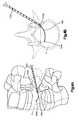
- the first guide wire 102is introduced through the skin and musculature and into the interior volume of the targeted damaged vertebral body V, as illustrated in Fig. 1 .
- the first guide wire 102is introduced through a single transverse process or through one of the pedicles.
- the working cannula 103is introduced over the first guidewire 102 until the distal end 103a of the working cannula 103 is placed adjacent to an exterior of the targeted vertebral body V, as illustrated in Fig. 2 .
- the distal end 103a of the working cannula 103may be placed with the interior volume of the vertebral body V.
- the first guidewire 102is then removed leaving the working cannula 103 in place, as illustrated in Fig. 3 .
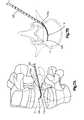
- the second guidewire 104is then introduced through the working cannula 103 and into the interior of the vertebral body V, as illustrated in Figs. 4A and 4B .
- the second guidewire 104Upon exiting the distal end 103a of the working cannula 103, the second guidewire 104 curves or bends toward an opposite side of the vertebral body V as the second guidewire 104 is being introduced into the interior volume of the vertebral body V.
- the second guidewire 104follows a path interior to the vertebral body V that has a concave side facing the posterior of the vertebral body V and a convex side facing the anterior of the vertebral body V.
- the distal end 104a of the second guidewire 104is preferably position proximate the posterior wall of the vertebral body V. The insertion and positioning of the second guidewire 104 creates an introduction pathway for subsequently introduced elements of the system.
- the plunger or cavity creation device 105is introduced over the second guidewire 104.
- the plunger or cavity creation device 105is directed along the path created by the second guidewire 104, as illustrated in Figs. 5A and 5B .
- the plunger or cavity creation device 105assists in further enlarging the introduction pathway for subsequently introduced elements of the system by creating a cavity along the exterior of the second guidewire 104 and thus enlarging the pathway created by the second guidewire 104.
- the exterior of the plunger 105may include corrugation or other exterior surface features to assist in developing the pathway.
- the plunger 105is then removed from the interior volume of the vertebral body V while retaining the second guidewire 104 and the working cannula 103 in place, as illustrated in Figs. 6A and 6B .
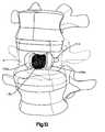
- the cannulated sleeve 108which includes the chassis 110 detachably coupled to the distal end thereof, is advanced through the working cannula 103 and into the interior volume of the vertebral body V along the introductory pathway created by the second guidewire 104 and the plunger or cavity creation device 105.
- the chassis 110is inserted and travels over the second guidewire 104.
- the slot 114 formed on the interior or exterior posterior surface of the chassis 110preferably interacts with the second guidewire 104 to steer the chassis 110 into position within the vertebral body V, as illustrated in Figs. 7A-8B .
- the folded containment device 125is protected from damage during insertion due to its partial enclosure by the chassis 110.
- the containment device 125may be introduced in a second step that occurs after positioning the chassis 110 - filling and expansion of the containment device 125 is preformed as described below.
- the containment device 125is then expanded via introduction of the bone filler matter (e.g., bone cement).
- the introduction of bone cementis preferably performed via a two step process. That is, a low viscosity bone cement is injected through the cannulated sleeve 108 and into the containment device 125 causing the containment device 125 to unfold and partially expand anteriorly out of the anterior window 111 formed in the chassis 110.
- a small amount of bone cementis secreted through the pores toward the anterior portion of the vertebral body V. Secretion of the bone cement through the pores preferably forms the cement bolus 130.
- a higher viscosity bone cementis then preferably injected through the cannulated sleeve 108 and into the containment device 125 to further expand the containment device 125.
- additional bone cementis secreted through the pores formed in the containment device 125.
- injection of the higher viscosity bone cementpreferably restores the height of the vertebral body V.
- the outflow of bone cement through the pores, resulting in the cement bolus 130,is preferably directed anteriorly to limit posterior or lateral cement flow within the vertebral body V. The posterior and lateral cement flow is limited by the barrier formed by the geometry of the expanded containment device 125 and the chassis 110.
- the secreted bone cement 130preferably provides interdigitation and stabilization to limit slippage between the containment device 125 and the surrounding bone tissue interior to the vertebral body V.
- the bone cement injected into the containment device 125provides height restoration and conservation of the spacing between the endplates of the vertebral body V.
- the barrier to posterior cement flow within the vertebral body Vthat is provided by the geometry of the expanded containment device 125 and the chassis 110 limits the bone cement from leaking through any fracture lines inherent on the posterior wall of the vertebral body V, a condition noted in about forty percent (40%) of all vertebral body fracture cases.
- the system and methoduses a two-step process for injecting the bone cement
- the system and methodis not so limited and the containment device 125 may be inflated using a single-step process or a process involving more than two steps.
- the introduction of the containment device 125 through a single transverse process or pedicle and the elongated curved or bent geometry of the second guidewire 104permits a less invasive procedure than a bi-pedicular or bi-transverse process approach in which a pair of devices or implants are introduced into the interior of the vertebral body V.
- the chassis 110is uncoupled from the distal end of the cannulated sleeve 108 by actuating or employing any of the above described appropriate detachment mechanisms, depending on the particular mechanism chosen for the system, at which point the cannulated sleeve 108 is removed from the working cannula 103.
- the working cannula 103 and the second guidewire 104are preferably removed from the patient's body, as illustrated in Figs. 12A-13 , while leaving the containment device 125 and chassis 110, as well as the cement bolus 130, within the interior of the vertebral body V.
- the containment device 125may be partially or fully removed from the vertebral body V by creating weakened portions in the containment device 125 along which the containment device 125 may tear to permit at least partial removal of the containment device 125 from the vertebral body V.
Landscapes
- Health & Medical Sciences (AREA)
- Orthopedic Medicine & Surgery (AREA)
- Life Sciences & Earth Sciences (AREA)
- Surgery (AREA)
- Neurology (AREA)
- General Health & Medical Sciences (AREA)
- Veterinary Medicine (AREA)
- Public Health (AREA)
- Animal Behavior & Ethology (AREA)
- Engineering & Computer Science (AREA)
- Biomedical Technology (AREA)
- Heart & Thoracic Surgery (AREA)
- Molecular Biology (AREA)
- Medical Informatics (AREA)
- Nuclear Medicine, Radiotherapy & Molecular Imaging (AREA)
- Biophysics (AREA)
- Pulmonology (AREA)
- Anesthesiology (AREA)
- Hematology (AREA)
- Epidemiology (AREA)
- Surgical Instruments (AREA)
- Prostheses (AREA)
Description
- Vertebral compression fractures ("VCF") represent a spinal injury and may result in prolonged disability. Generally, VCF involves the collapse of one or more vertebral bodies in the spine. VCF usually occurs in the lower vertebrae of the thoracic spine or the upper vertebrae of the lumbar spine. The anterior portion of the vertebral body is typically collapsed to a further extent than a posterior portion, resulting in a potentially wedge-shaped, compressed vertebral body, during a VCF event. VCF may result in deformation of the normal alignment or curvature,e.g., lordosis, of the vertebral bodies in the affected area of the spine. VCF and/or related spinal deformities may initiate from, for example, metastatic diseases of the spine, trauma and/or osteoporosis. Until recently, doctors were limited in their treatment options for VCF and related spinal deformities.
- Minimally invasive surgical procedures for treating VCF have been developed. A cannula or other access tools are typically inserted through the posterior of the targeted vertebral body, usually through the pedicles in such procedures. For example,
U.S. Published Patent Application No. 2009-0069850 describes a balloon with an implant mounted thereon that is insertable through a posterior duct into a compressed vertebral body and expanded to urge endplates of the vertebral body toward an original spacing or shape. - In another such procedure, generally referred to as vertebralplasty, a cannula or bone needle is passed through the soft tissue of the patient's back. Once positioned within the compressed vertebral body, a small amount of polymethylmethacrylate (PMMA) or other orthopedic bone cement is pushed through the needle into the targeted vertebral body. This technique may be effective in the reduction or elimination of fracture pain, prevention of further collapse, and a return to mobility in patients. However, this technique typically does not reposition the fractured bone into its original size and/or shape and, therefore, may not address the problem of spinal deformity due to the fracture.
- Other treatments for VCF generally involve two phases including (1) reposition or restoration of the original height of the vertebral body and consequent lordotic correction of the spinal curvature; and (2) augmentation or addition of material to support or strengthen the fractured or collapsed vertebral body. This procedure is generally referred to as Kyphoplasty and is generally described in
U.S. Patent No. 6,241,734 . - One such treatment involves inserting a catheter having a balloon mounted on a distal end into an interior volume of a fractured vertebral body, wherein the interior volume has a relatively soft cancellous bone surrounded by fractured cortical bone. The balloon is expanded within the interior volume in an attempt to restore the vertebral body towards its original height. The balloon is deflated and removed from the interior volume, leaving a void within the vertebral body. PMMA or other bone filler material is injected through the cannula into the void to stabilize the vertebral body. The cannula is then removed and the cement cures to augment, fill, or fix the size and general shape of the vertebral body. Such treatment is described e.g. in
WO 98/56301 A1 - Another approach for treating VCF involves inserting an expandable mesh balloon into the targeted vertebral body. The balloon remains inside the vertebral body after it is inflated with PMMA or an allograft product, which limits intra-operative loss of height of the repositioned endplates. This is known e.g. from
US 2002/0058947 A1 .US 2009/0030468 A1 discloses a braided balloon that serves as a bone cement-directing structure. The balloon has regions of differential permeability to the bone cement. [0008] It is desirable to provide an improved system, method and instruments for minimally invasively inserting a containment device such as, for example, an implant or a balloon, into an interior volume of a patient's bone. - The present invention relates to a device as claimed hereafter. Preferred embodiments of the invention are set forth in the dependent claims.
- The present invention relates generally to a system and instrumentation for augmenting bones or other structures such as, for example, a vertebral body. More specifically, the present invention relates to an improved system for inserting a containment device, implant, balloon,etc. into an interior volume of a patient's vertebral body for the treatment of compressed bone voids, more specifically, vertebral compression fractures.
- In a first preferred embodiment of the present invention, the system for accessing and inserting a containment device within an interior volume of a vertebral body includes an expandable containment, a first guidewire, a working cannula, a second guidewire, a sleeve and a chassis. The expandable containment device includes an outer surface encasing an interior cavity, and a first end portion, a second end portion, and a middle portion located between the first and second end portions and having a circumference smatter than a circumference of either end portion. The chassis includes an interior cavity for at least partially enclosing the expandable containment device. The working cannula includes a proximal end, a distal end and a hollow interior passageway extending from the proximal end to the distal end. The second guidewire includes a partially flexible distal end portion such that the distal end portion can generally extend laterally across an anterior portion of the vertebral body in an insertion position. The sleeve includes a proximal portion, a distal portion and a cannulated passageway extending from the proximal portion to the distal portion. The sleeve being sized and configured for insertion into the interior passageway of the working cannula. The distal portion of the sleeve being detachably coupled to the chassis while the proximal portion is preferably operatively associated with a bone filler injecting mechanism for introducing bone filler material through the cannulated passageway of the sleeve and into the interior cavity of the containment device.
- The system preferably also includes a plunger including a partially flexible distal end portion and a cannulated bore so that the plunger can be advanced over the second guidewire.
- The chassis preferably includes a leading end, a trailing end, an anterior portion and a posterior portion, the anterior portion including a window to enable and direct the outward expansion of the expandable containment device as the bone filler material is being introduced. The containment device preferably includes a plurality of anteriorly disposed cement-directing pores.
- A preferred method, not claimed, for augmenting a vertebral body requires the steps of: (a) inserting a first guidewire into the interior of the vertebral body through one of a transverse process and a pedicle of the vertebral body; (b) advancing a working cannula over the first guidewire and into contact with the vertebral body; (c) removing the first guidewire from the vertebral body while retaining the position of the working cannula; (d) advancing a second guidewire through the working cannula and into the interior of the vertebral body, the second guidewire preferably assumes a curved configuration upon exiting a distal end of the working cannula so that a convex side of the second guidewire faces the anterior portion of the vertebral body and a concave side of the second guidewire faces the posterior portion of the vertebral body in an inserted configuration, advancement of the second guidewire into the interior of the vertebral body creates a curvilinear introductory pathway; (e) advancing a plunger through the working cannula and over the second guidewire to increase a dimension of the curvilinear introductory pathway created by the second guidewire, the plunger including a curved distal portion that is slidable through the working cannula and assumes a curved configuration upon exiting the distal end of the working cannula; (f) removing the plunger while retaining the positions of the second guidewire and the working cannula; (g) advancing a cannulated sleeve through the working cannula and along the second guidewire, the cannulated sleeve detachably coupled at a distal end thereof to a chassis, the chassis at least partially surrounding an expandable containment device, the chassis including an anteriorly facing window for directing the expansion of the expandable containment device; (h) introducing a bone cement through the cannulated sleeve and into the expandable containment device, thereby causing the expandable containment device to expand anteriorly out of the window formed in the chassis and to secrete a bolus of bone cement anteriorly with respect to the chassis; (i) uncoupling and removing the distal end of the cannulated sleeve from the proximal end of the chassis and (j) removing the second guidewire.
- The bone cement introduction step preferably includes a two-step process wherein an amount of a lower viscosity cement is introduced followed by introducing an amount of a higher viscosity cement.
- The foregoing summary, as well as the following detailed description of preferred embodiments of the augmentation and stabilization system, method, not claimed, and instrumentation of the present application, will be better understood when read in conjunction with the appended drawings. For the purposes of illustrating the minimally invasive spine augmentation and stabilization system, method , not claimed, and instrumentation of the present application, there is shown in the drawings preferred embodiments. It should be understood, however, that the application is not limited to the precise arrangements and instrumentalities shown. In the drawings:
Figs. 1-13 illustrate various steps of practicing a preferred method, not claimed, of a minimally invasive spine augmentation and stabilization system of the present invention, with portions of a vertebra being generally transparent for clarity;Fig. 14A illustrates a front perspective view of a chassis of the minimally invasive spine augmentation and stabilization system; andFig. 14B illustrates a top plan, partial cross-sectional view of the chassis ofFig. 14A .- Certain terminology is used in the following description for convenience only and is not limiting. The words "right", "left", "lower" and "upper" designate directions in the drawings to which reference is made. The words "inwardly" or "distally" and "outwardly" or "proximally" refer to directions toward and away from, respectively, the patient's body, or the geometric center of the minimally invasive spine augmentation and stabilization system and related parts thereof. The words, "anterior", "posterior", "superior," "inferior", "medial", "lateral" and related words and/or phrases designate preferred positions and orientations in the human body to which reference is made and are not meant to be limiting. The terminology includes the above-listed words, derivatives thereof and words of similar import.
- Certain exemplary embodiments will now be described with reference to the drawings. In general, such embodiments relate to a system, method and instrumentation for inserting an implant, containment device or balloon (collectively referred to herein as a containment device 125) within an interior volume of a vertebral body V. Once inserted, the
containment device 125 preferably creates a cavity within the interior volume of the vertebral body V, restores the height of the vertebral body V, fills the cavity formed in the vertebral body V and stabilizes, aids and/or augments the patient's vertebral body V and spine. As generally understood by one of ordinary skill in the art, it should be understood that while thepreferred containment device 125 will be described as and may generally be used in the spine (for example, in the lumbar, thoracic or cervical regions), those skilled in the art will appreciate that thecontainment device 125 may be used in other parts of the body such as, for example, long bones or bones in the hand, face, feet, extremities, cranium, or in nearly any bone in the human body. - Referring to
Figs. 10A-13 and as disclosed in International Patent Application No.PCT/US2008/083350 (published application No.WO 2009/064847 A2), filed November 13, 2008 , titled "Porous Containment Device and Associated Method for Stabilization of Vertebral Compression Fractures, which claims priority toU.S. Provisional Patent Application No. 60/988,696, filed November 16, 2007 permeable containment device 125 for implantation into the interior volume of a targeted vertebral body V for use in restoring the anatomy of the targeted vertebral body V. Thecontainment device 125 is expandable from an insertion configuration to an expanded configuration via, for example, a bone filler material such as, for example, a bone cement. Expansion of thecontainment device 125 by injection of the bone filler material preferably facilitates (i) cavity creation within the interior volume of the targeted vertebral body V, (ii) height restoration of the targeted vertebral body V, (iii) filling of the cavity formed in the interior volume of the targeted vertebral body V, and (iv) stabilization, aiding and/or augmentation of the targeted vertebral body V. The porous orpermeable containment device 125 preferably enables (i) controlled bone cement outflow, (ii) increased contact surface with the surrounding cancellous bone and (iii) stabilization of the rotational and axial-translational movements of theporous containment device 125 with respect to the surrounding cancellous bone. - The
containment device 125 may be formed from a compliant, semi-compliant or non-compliant material. Thecontainment device 125 is preferably constructed from a PEEK material and is designed to have a pre-determined, specific shape when in the expanded configuration. More preferably, thecontainment device 125 has a dogbone-like or barbell-like shape in the expanded configuration to enhance stabilization with the surrounding cancellous bone. That is, thecontainment device 125, upon expansion or inflation, includes aleading end portion 125a, a trailingend portion 125b and amiddle portion 125c therebetween such that thecontainment device 125 has first and second bulbous end portions and a comparatively narrow middle portion. - The
containment device 125 preferably permits the bone filler material to flow out of or through the outer surface of thecontainment device 125. Preferably, thecontainment device 125 includes a plurality of holes or pores (not shown) formed in the outer surface for secreting the bone filler material. Preferably, the plurality of holes or pores are position in the anterior-facing surface of themiddle portion 125c of thecontainment device 125 to direct the excretion of the bone filler material anteriorly out of thecontainment device 125 as thecontainment device 125 expands via injection of the bone filler material. The geometry of thecontainment device 125 in the expanded configuration serves as a barrier to confine the excreted bolus ofbone filler material 130 anterior to the expandedcontainment device 125 and to limit bone filler material from flowing posteriorly or laterally with respect to themiddle portion 125c of thecontainment device 125. The pores or holes may also incorporate a specifically designed shape and configuration to optimally meet the requirements of secreting the bone filler material, tissue infiltration and anchorage of thecontainment device 125 to the - surrounding bone tissue.
- Alternatively, the
containment device 125 may include one or more flow-directing tentacles (not shown) extending from the outer surface or be formed at least partially from a permeable material,etc. to enable the bone filler material to be secreted from thecontainment device 125 to interdigitate with the surrounding bone tissue. - The
containment device 125 may also include one or more knobs or ribs (not shown) to facilitate anchoring of thecontainment device 125 to the surrounding bone tissue, one or more air or fluid evacuation pores (not shown) to permit air or fluid from escaping from the interior volume of thecontainment device 125, and/or one or more radiopacity rings or markers (not shown) to enable a surgeon to locate and/or position thecontainment device 125 under X-ray imaging. - It should be understood that while the system, method and instrumentation of the present invention is preferably used in connection with the insertion of the
containment device 125 disclosed in International Patent Application No.PCT/US2008/083350 (WO 2009/064847 A2 ), the present invention is not so limited and may be used in conjunction with other now known or hereafter developed containment devices. - Referring to
Figs. 1-13 , the system and instrumentation of a preferred embodiment for accessing and inserting thecontainment device 125 within the interior volume of a targeted collapsed, fractured, or otherwise damaged vertebral body V is illustrated. As generally understood by one of ordinary skill in the art, the targeted vertebral body V includes an anterior side, a posterior side, lateral sides therebetween, a superior portion, an inferior portion with a height therebetween, a spinous process, first and second transverse processes, and an intervertebral disc that is adhered both superiorly and inferiorly with respect to the damaged vertebral body V and which separates the damaged vertebral body V from adjacent vertebral bodies or vertebrae. The damaged vertebral body V is shown in a generally transparent configuration inFigs. 1-13 to generally improve clarity of the components and steps of the preferred minimally invasive spine augmentation and stabilization system and method. - Referring to
Figs. 1-4B , the system preferably includes a rigidfirst guidewire 102, a workingcannula 103 and asecond guidewire 104. Thefirst guidewire 102 may be a stylet, a K-wire, a guide pin,etc. The workingcannula 103 preferably includes a proximal end (not shown), adistal end 103a and a hollow interior passageway (not shown) extending from the proximal end to thedistal end 103a for enabling other instruments or elements to be advanced into the targeted vertebral body V. Thesecond guidewire 104, which may also be in the form of a stylet, K-wire or guide pin, is designed and constructed so that at least adistal portion 104a thereof is at least partially flexible. In this manner, thesecond guidewire 104 includes a curveddistal portion 104a. The curveddistal portion 104a of thesecond guidewire 104 may be constructed by manufacturing thesecond guidewire 104 from a shape memory material so that the curveddistal portion 104a of thesecond guide wire 104 can assume a straight configuration so that it can be inserted through the hollow interior passageway of the workingcannula 103. Thereafter, at least thedistal portion 104a of thesecond guidewire 104 reassumes, bends or curves upon exiting thedistal end 103a of the workingcannula 103. - It should be noted that the
second guidewire 104 is not limited to being manufactured from a shape memory material and that thesecond guidewire 104 may be manufactured from any material as long as thedistal portion 104a thereof is designed and constructed to have a curved or bent distal end such that thedistal end 104a generally extends laterally across an anterior portion of the vertebral body V when thesecond guidewire 104 extends out of thecannula 103 in an insertion position. - Referring to
Figs. 5A and 5B , the system preferably also includes a hollow plunger or othercavity creation device 105 that is advanceable over thesecond guidewire 104 and into the vertebral body V. The plunger or othercavity creation device 105 is guided along the path created by thesecond guidewire 104. The plunger or othercavity creation device 105 assists in further creating or enlarging the introduction pathway for subsequently introduced elements of the system by creating a cavity along the exterior of thesecond guidewire 104 and thus enlarging the pathway created by thesecond guidewire 104. The exterior of theplunger 105 may include corrugation or other exterior surface features to assist in developing the pathway. - The hollow plunger or
cavity creation device 105 is preferably at least partially flexible and includes a bendable or curveabledistal portion 105a so that upon exiting thedistal end 103a of the workingcannula 103, thedistal portion 105a of the plunger orcavity creation device 105 bends or curves to follow the path of thesecond guidewire 104. As with thesecond guidewire 104, the plunger orcavity creation device 105 may be manufactured from a shape memory material so that thedistal portion 105a of the plunger orcavity creation device 105 initially assumes a straight configuration so that it can be inserted through the hollow interior passageway of the workingcannula 103. Thereafter, at least thedistal portion 105a of the plunger orcavity creation device 105 reassumes a distally bent or curved shape upon exiting thedistal end 103a of the workingcannula 103. - It should be noted that the plunger or
cavity creation device 105 is not limited to being manufactured from a shape memory material and that the plunger orcavity creation device 105 may be manufactured from any material as long as thedistal portion 105a thereof is designed and constructed to have a curved or bent distal end such that thedistal end 105a is capable of bending or curving to follow the path of thesecond guidewire 104. For example, the plunger orcavity creation device 105 may be generally flexible to follow the path of thesecond guidewire 104 to direct thedistal end 105a of the plunger orcavity creation device 105 along the path defined by thesecond guidewire 104 within the vertebral body V. - Referring to
Figs. 7A-14B , the system preferably also includes a cannulatedsleeve 108, acontainment device chassis 110 and thecontainment device 125. The cannulatedsleeve 108 includes a proximal portion (not shown), a distal portion (not shown) and a interior passageway extending from the proximal portion to the distal portion. In use, the cannulatedsleeve 108 is sized and configured to be inserted into the interior passageway of the workingcannula 103. The distal portion of the cannulatedsleeve 108 is preferably detachably coupled to thecontainment device chassis 110. The proximal portion is preferably coupleable with a mechanism such as, for example, a syringe (not shown) for introducing bone filler material or bone cement through the cannulatedsleeve 108 and into the interior of thecontainment device 125, which is preferably housed inside of thechassis 110. - As best shown in
Figs. 14A and 14B , thechassis 110 includes aleading end 110a and a trailingend 110b wherein theleading end 110a may include a bullet nose tip or other taper for ease of advancement within the interior of the vertebral body V. As previously mentioned, the trailingend 110b is detachably coupled to the cannulatedsleeve 108. Thechassis 110 preferably also includes ahollow cavity 110c sized and configured to house or contain thecontainment device 125 when thecontainment device 125 is in the insertion configuration. An anterior portion of thechassis 110 preferably includes awindow 111 to direct outward expansion of thecontainment device 125 upon inflation with the bone filler material or bone cement. Thechassis 110 preferably has a curvature similar to the curvature of thedistal end 104a of thesecond guidewire 104 and thedistal end 105a of the plunger orcavity creation device 105. As such, thechassis 110 may be manufactured from a shape memory material so that thechassis 110 assumes the shape of the hollow interior passageway of the workingcannula 103, as thechassis 110 is being inserted through the workingcannula 103. Upon exiting thedistal end 103a of the workingcannula 103, thechassis 110 preferably reassume its curved shape. - It should be noted that the
chassis 110 is not limited to being manufactured from a shape memory material and that thechassis 110 may be manufactured from any material as long as thechassis 110 is curveable or bendable to follow the path of thesecond guidewire 104. Thechassis 110 is preferably formed from a material such as polyetheretherketone (PEEK), Nitinol, titanium,etc., but is not so limited. The posterior exterior or interior surface of thechassis 110 preferably includes a groove or slot 114 that is configured to mate with thesecond guide wire 104 such that thechassis 110 can be directed along thesecond guide wire 104 and into a desired position within the interior of the damaged vertebral body V. - The detachable coupling between the
proximal end 110b of thechassis 110 and the distal end of the cannulatedsleeve 108 may be by any mechanism now or hereafter known including, but not limited to, a friction fit, a press fit, or a force fit. In this manner, the cannulatedsleeve 108 may be coupled to thechassis 110 by pressure and all forces can be transmitted by friction. In use, thechassis 110 can be decoupled from the cannulatedsleeve 108 by holding thechassis 110 in place and pulling the cannulatedsleeve 108 away from thechassis 110. Alternatively, the cannulatedsleeve 108 may be coupled to thechassis 110 by a threaded connection, a bayonet coupling, or a plug-in connector such as by a pin formed in the cannulatedsleeve 108 for engaging a slot formed in thechassis 110. - Alternatively, the cannulated
sleeve 108 may be coupled to thechassis 110 via deformation of an elastic element (not shown). That is, the cannulatedsleeve 108 may include an inner cannulated sleeve (not shown) and an outer cannulated sleeve (not shown) wherein the outer cannulated sleeve is movably associated with the inner cannulated sleeve. The elastic element may surround the inner cannulated sleeve, preferably adjacent the distal end thereof. The inner cannulated sleeve and elastic element are inserted into thechassis 110. Thereafter the outer cannulated sleeve is moved relative to the inner cannulated sleeve so that the distal end of the outer cannulated sleeve contacts the elastic element. Continued movement of the outer cannulated sleeve causes the elastic element to deform, resulting in the elastic element increasing in diameter which, in turn, causes the elastic element to press against the inner surface of thechassis 110. - Alternatively, the outer cannulated sleeve may be coupled to the elastic compression ring so that movement of the inner cannulated sleeve with respect to the outer cannulated sleeve causes the inner cannulated sleeve to contact and subsequently compress the elastic compression ring, which in turn causes the compression ring to expand and press against the
chassis 110. - Furthermore, the cannulated
sleeve 108 may be coupled to thechassis 110 by an intermediate clamping element (not shown). For example, the cannulatedsleeve 108 may include an inner cannulated sleeve (not shown) and an outer cannulated sleeve (not shown) wherein the outer cannulated sleeve is movably associated with the inner cannulated sleeve. The intermediate clamping element may be formed on or coupled to the inner cannulated sleeve, preferably on the outer surface of the inner cannulated sleeve adjacent to a distal end thereof. Thechassis 110 is thereafter placed between the inner cannulated sleeve and the intermediate clamping element. Thereafter movement of the outer cannulated sleeve with respect to the inner cannulated sleeve causes the outer cannulated sleeve to move over the intermediate clamping element thus securing thechassis 110. In addition, the cannulatedsleeve 108 may be integrally formed with thechassis 110. The integrally formed cannulatedsleeve 108 andimplant chassis 110 may be separated by a predefined breaking region such that during the procedure thechassis 110 is separated from the cannulatedsleeve 108 by rupturing the breaking region. - In continuing reference to
Figs. 1-13 , a preferred method, not claimed, of inserting thecontainment device 125 within the interior volume of the targeted vertebral body V will now be described. After a damaged vertebral body V in need of repair is identified, thefirst guide wire 102 is introduced through the skin and musculature and into the interior volume of the targeted damaged vertebral body V, as illustrated inFig. 1 . Thefirst guide wire 102 is introduced through a single transverse process or through one of the pedicles. Next, the workingcannula 103 is introduced over thefirst guidewire 102 until thedistal end 103a of the workingcannula 103 is placed adjacent to an exterior of the targeted vertebral body V, as illustrated inFig. 2 . Alternatively, thedistal end 103a of the workingcannula 103 may be placed with the interior volume of the vertebral body V. Thefirst guidewire 102 is then removed leaving the workingcannula 103 in place, as illustrated inFig. 3 . - The
second guidewire 104 is then introduced through the workingcannula 103 and into the interior of the vertebral body V, as illustrated inFigs. 4A and 4B . Upon exiting thedistal end 103a of the workingcannula 103, thesecond guidewire 104 curves or bends toward an opposite side of the vertebral body V as thesecond guidewire 104 is being introduced into the interior volume of the vertebral body V. As thesecond guidewire 104 curves or bends, thesecond guidewire 104 follows a path interior to the vertebral body V that has a concave side facing the posterior of the vertebral body V and a convex side facing the anterior of the vertebral body V. Thedistal end 104a of thesecond guidewire 104 is preferably position proximate the posterior wall of the vertebral body V. The insertion and positioning of thesecond guidewire 104 creates an introduction pathway for subsequently introduced elements of the system. - Once the
second guidewire 104 is positioned within the interior volume of the vertebral body V, the plunger orcavity creation device 105 is introduced over thesecond guidewire 104. The plunger orcavity creation device 105 is directed along the path created by thesecond guidewire 104, as illustrated inFigs. 5A and 5B . The plunger orcavity creation device 105 assists in further enlarging the introduction pathway for subsequently introduced elements of the system by creating a cavity along the exterior of thesecond guidewire 104 and thus enlarging the pathway created by thesecond guidewire 104. The exterior of theplunger 105 may include corrugation or other exterior surface features to assist in developing the pathway. Theplunger 105 is then removed from the interior volume of the vertebral body V while retaining thesecond guidewire 104 and the workingcannula 103 in place, as illustrated inFigs. 6A and 6B . - Next, the cannulated
sleeve 108, which includes thechassis 110 detachably coupled to the distal end thereof, is advanced through the workingcannula 103 and into the interior volume of the vertebral body V along the introductory pathway created by thesecond guidewire 104 and the plunger orcavity creation device 105. Thechassis 110 is inserted and travels over thesecond guidewire 104. To assist in this matter, theslot 114 formed on the interior or exterior posterior surface of thechassis 110 preferably interacts with thesecond guidewire 104 to steer thechassis 110 into position within the vertebral body V, as illustrated inFigs. 7A-8B . The foldedcontainment device 125 is protected from damage during insertion due to its partial enclosure by thechassis 110. - Alternatively, the
containment device 125 may be introduced in a second step that occurs after positioning the chassis 110 - filling and expansion of thecontainment device 125 is preformed as described below. - Referring to
Figs. 9A-11B , thecontainment device 125 is then expanded via introduction of the bone filler matter (e.g., bone cement). The introduction of bone cement is preferably performed via a two step process. That is, a low viscosity bone cement is injected through the cannulatedsleeve 108 and into thecontainment device 125 causing thecontainment device 125 to unfold and partially expand anteriorly out of theanterior window 111 formed in thechassis 110. In addition, a small amount of bone cement is secreted through the pores toward the anterior portion of the vertebral body V. Secretion of the bone cement through the pores preferably forms thecement bolus 130. Next, a higher viscosity bone cement is then preferably injected through the cannulatedsleeve 108 and into thecontainment device 125 to further expand thecontainment device 125. Moreover, additional bone cement is secreted through the pores formed in thecontainment device 125. In addition, injection of the higher viscosity bone cement preferably restores the height of the vertebral body V. The outflow of bone cement through the pores, resulting in thecement bolus 130, is preferably directed anteriorly to limit posterior or lateral cement flow within the vertebral body V. The posterior and lateral cement flow is limited by the barrier formed by the geometry of the expandedcontainment device 125 and thechassis 110. - The secreted
bone cement 130 preferably provides interdigitation and stabilization to limit slippage between thecontainment device 125 and the surrounding bone tissue interior to the vertebral body V. In addition, the bone cement injected into thecontainment device 125 provides height restoration and conservation of the spacing between the endplates of the vertebral body V. The barrier to posterior cement flow within the vertebral body V that is provided by the geometry of the expandedcontainment device 125 and thechassis 110 limits the bone cement from leaking through any fracture lines inherent on the posterior wall of the vertebral body V, a condition noted in about forty percent (40%) of all vertebral body fracture cases. - It should be understood that while the preferred method, not claimed, uses a two-step process for injecting the bone cement, the system and method is not so limited and the
containment device 125 may be inflated using a single-step process or a process involving more than two steps. - The introduction of the
containment device 125 through a single transverse process or pedicle and the elongated curved or bent geometry of thesecond guidewire 104 permits a less invasive procedure than a bi-pedicular or bi-transverse process approach in which a pair of devices or implants are introduced into the interior of the vertebral body V. Upon desired expansion of thecontainment device 125 and creation of thecement bolus 130, thechassis 110 is uncoupled from the distal end of the cannulatedsleeve 108 by actuating or employing any of the above described appropriate detachment mechanisms, depending on the particular mechanism chosen for the system, at which point the cannulatedsleeve 108 is removed from the workingcannula 103. The workingcannula 103 and thesecond guidewire 104 are preferably removed from the patient's body, as illustrated inFigs. 12A-13 , while leaving thecontainment device 125 andchassis 110, as well as thecement bolus 130, within the interior of the vertebral body V. Alternatively, thecontainment device 125 may be partially or fully removed from the vertebral body V by creating weakened portions in thecontainment device 125 along which thecontainment device 125 may tear to permit at least partial removal of thecontainment device 125 from the vertebral body V. - It will be appreciated by those skilled in the art that changes could be made to the embodiment described above without departing from the broad inventive concept thereof. It is understood, therefore, that this invention is not limited to the particular embodiment disclosed, but it is intended to cover modifications within the scope of the present invention as defined by the present description.
Claims (8)
- A system for accessing and inserting a containment device within an interior volume of a vertebral body (V), the system comprising:an expandable containment device (125) including an outer surface encasing an interior cavity;a first guidewire (102);a working cannula (103) including a proximal end, a distal end (103a) and a hollow interior passageway extending from the proximal end to the distal end (103a);a second guidewire (104) having at least a partially flexible distal end portion (104a) such that the distal end portion (104a) generally extends laterally across an anterior portion of the vertebral body (V) when the second guidewire (104) extends out of the cannula (103) in an insertion position; anda sleeve (108) including a proximal portion, a distal portion and a cannulated passageway extending from the proximal portion to the distal portion, the sleeve (108) being sized and configured to be inserted into the interior passageway of the working cannula (103),characterized in that the system further comprises a chassis (110) including an interior cavity (110c) for at least partially enclosing the expandable containment device (125),wherein the distal portion of the sleeve (108) is detachably coupled to the chassis (110), the proximal portion of the sleeve being operatively associated with a bone filler injecting mechanism for introducing bone filler material through the cannulated passageway of the sleeve (108) and into the interior cavity of the containment device (125), andwherein the expandable containment device (125) further includes a first end portion (125a), a second end portion (125b), a middle portion (125c) located between the first and second end portions (125a, 125b), the middle portion (125c) having a circumference smaller than a circumference of either end portion (125a, 125b).
- The system of claim 1, further comprising a plunger (105), the plunger (105) including at least a partially flexible distal end portion (105a) and a cannulated bore so that the plunger (105) can be advanced over the second guidewire (104).
- The system of claim 1 or 2, wherein the chassis (110) includes a leading end (110a), a trailing end (110b), an anterior portion and a posterior portion, the anterior portion including a window (111) to enable and direct the outward expansion of the expandable containment device (125) as the bone filler material is being introduced.
- The system of claim 3, wherein the leading end (110a) of the chassis includes a taper nose.
- The system of claim 3 or 4, wherein the chassis (110) has a curvature similar to a curvature of the flexible distal end portion (104a) of the second guidewire (104).
- The system of any one of claims 3 to 5, wherein a posterior exterior or interior surface of the chassis (110) includes a groove or slot (114) that is configured to mate with the second guide wire (104) such that the chassis (110) can be directed along the second guide wire (104) and into a desired position within the interior volume of the vertebral body (V).
- The system of any one of claims 1 to 6, wherein at least a portion of the middle portion (125c) of the containment device (125) includes a plurality of anteriorly disposed cement-directing pores.
- The system of any one of claims 1 to 7, wherein the second guidewire (104) is manufactured from a shape memory material so that the distal portion (104a) of the second guide (104) wire can assume a straight configuration for insertion through the hollow interior passageway of the working cannula (103) and thereafter reassume a bent or curved configuration upon exiting the distal end (103a) of the working cannula (103).
Applications Claiming Priority (2)
| Application Number | Priority Date | Filing Date | Title |
|---|---|---|---|
| US16804609P | 2009-04-09 | 2009-04-09 | |
| PCT/US2010/030089WO2010118021A1 (en) | 2009-04-09 | 2010-04-06 | Minimally invasive spine augmentation and stabilization system and method |
Publications (2)
| Publication Number | Publication Date |
|---|---|
| EP2416721A1 EP2416721A1 (en) | 2012-02-15 |
| EP2416721B1true EP2416721B1 (en) | 2013-07-10 |
Family
ID=42225115
Family Applications (1)
| Application Number | Title | Priority Date | Filing Date |
|---|---|---|---|
| EP10713098.1AActiveEP2416721B1 (en) | 2009-04-09 | 2010-04-06 | Minimally invasive spine augmentation and stabilization system |
Country Status (9)
| Country | Link |
|---|---|
| US (1) | US8911497B2 (en) |
| EP (1) | EP2416721B1 (en) |
| JP (1) | JP5662999B2 (en) |
| KR (1) | KR20120028873A (en) |
| CN (1) | CN102448393A (en) |
| BR (1) | BRPI1014890A2 (en) |
| CA (1) | CA2757829A1 (en) |
| ES (1) | ES2430913T3 (en) |
| WO (1) | WO2010118021A1 (en) |
Families Citing this family (54)
| Publication number | Priority date | Publication date | Assignee | Title |
|---|---|---|---|---|
| US8361067B2 (en) | 2002-09-30 | 2013-01-29 | Relievant Medsystems, Inc. | Methods of therapeutically heating a vertebral body to treat back pain |
| US20180228621A1 (en) | 2004-08-09 | 2018-08-16 | Mark A. Reiley | Apparatus, systems, and methods for the fixation or fusion of bone |
| US7988735B2 (en)* | 2005-06-15 | 2011-08-02 | Matthew Yurek | Mechanical apparatus and method for delivering materials into the inter-vertebral body space for nucleus replacement |
| US8114156B2 (en)* | 2008-05-30 | 2012-02-14 | Edwin Burton Hatch | Flexibly compliant ceramic prosthetic meniscus for the replacement of damaged cartilage in orthopedic surgical repair or reconstruction of hip, knee, ankle, shoulder, elbow, wrist and other anatomical joints |
| CA2737374C (en) | 2008-09-26 | 2017-03-28 | Relievant Medsystems, Inc. | Systems and methods for navigating an instrument through bone |
| US10028753B2 (en) | 2008-09-26 | 2018-07-24 | Relievant Medsystems, Inc. | Spine treatment kits |
| US8998925B2 (en)* | 2011-06-20 | 2015-04-07 | Rdc Holdings, Llc | Fixation system for orthopedic devices |
| US8814873B2 (en) | 2011-06-24 | 2014-08-26 | Benvenue Medical, Inc. | Devices and methods for treating bone tissue |
| US9724132B2 (en) | 2011-08-31 | 2017-08-08 | DePuy Synthes Products, Inc. | Devices and methods for cervical lateral fixation |
| AU2012362524B2 (en) | 2011-12-30 | 2018-12-13 | Relievant Medsystems, Inc. | Systems and methods for treating back pain |
| US9044321B2 (en) | 2012-03-09 | 2015-06-02 | Si-Bone Inc. | Integrated implant |
| US10363140B2 (en) | 2012-03-09 | 2019-07-30 | Si-Bone Inc. | Systems, device, and methods for joint fusion |
| EP3818947B1 (en) | 2012-05-04 | 2023-08-30 | SI-Bone, Inc. | Fenestrated implant |
| CN104582639A (en) | 2012-05-29 | 2015-04-29 | Nlt-脊椎有限公司 | Laterally deflectable implant |
| US10588691B2 (en) | 2012-09-12 | 2020-03-17 | Relievant Medsystems, Inc. | Radiofrequency ablation of tissue within a vertebral body |
| WO2014071161A1 (en) | 2012-11-05 | 2014-05-08 | Relievant Medsystems, Inc. | System and methods for creating curved paths through bone and modulating nerves within the bone |
| CN103027731A (en)* | 2012-12-29 | 2013-04-10 | 陈秋良 | Vertebral body support for vertebral body bone cement implanting operation |
| US10085783B2 (en) | 2013-03-14 | 2018-10-02 | Izi Medical Products, Llc | Devices and methods for treating bone tissue |
| US9572676B2 (en)* | 2013-03-14 | 2017-02-21 | DePuy Synthes Products, Inc. | Adjustable multi-volume balloon for spinal interventions |
| US9480574B2 (en) | 2013-03-14 | 2016-11-01 | Benvenue Medical, Inc. | Spinal fusion implants and devices and methods for deploying such implants |
| US9585761B2 (en) | 2013-03-14 | 2017-03-07 | DePuy Synthes Products, Inc. | Angulated rings and bonded foils for use with balloons for fusion and dynamic stabilization |
| US9358120B2 (en) | 2013-03-14 | 2016-06-07 | DePuy Synthes Products, Inc. | Expandable coil spinal implant |
| WO2014145902A1 (en) | 2013-03-15 | 2014-09-18 | Si-Bone Inc. | Implants for spinal fixation or fusion |
| US9724151B2 (en) | 2013-08-08 | 2017-08-08 | Relievant Medsystems, Inc. | Modulating nerves within bone using bone fasteners |
| US11147688B2 (en) | 2013-10-15 | 2021-10-19 | Si-Bone Inc. | Implant placement |
| CN103690228B (en)* | 2013-12-12 | 2015-11-25 | 宁波华科润生物科技有限公司 | Centrum expansion ball bag system |
| US10314605B2 (en)* | 2014-07-08 | 2019-06-11 | Benvenue Medical, Inc. | Apparatus and methods for disrupting intervertebral disc tissue |
| US10166033B2 (en)* | 2014-09-18 | 2019-01-01 | Si-Bone Inc. | Implants for bone fixation or fusion |
| JP6542362B2 (en) | 2014-09-18 | 2019-07-10 | エスアイ−ボーン・インコーポレイテッドSi−Bone, Inc. | Matrix implant |
| KR101647457B1 (en)* | 2014-11-25 | 2016-08-10 | 주식회사 메드릭스 | Band coupling device for spinous process |
| CN104546089A (en)* | 2015-01-09 | 2015-04-29 | 彭大勇 | Percutaneous puncture transverse balloon distraction percutaneous kyphoplasty surgical instrument |
| US10022243B2 (en) | 2015-02-06 | 2018-07-17 | Benvenue Medical, Inc. | Graft material injector system and method |
| CN105167836B (en)* | 2015-08-07 | 2017-12-08 | 昆明医科大学第一附属医院 | A kind of guided by saccule device for the operation of pedicle of vertebral arch approach kyphoplasty |
| CN106420033B (en)* | 2016-09-28 | 2023-06-20 | 上海凯利泰医疗科技股份有限公司 | Bone filler push injection system |
| CN106388924A (en)* | 2016-09-28 | 2017-02-15 | 上海凯利泰医疗科技股份有限公司 | Bone filler injecting system |
| ES2672265B1 (en)* | 2016-11-07 | 2019-04-10 | Inst Biomecanico De Barcelona S L | DEVICE FOR INTERVERTEBRAL FUSION COMPRISING AN INTERVERTEBRAL STABILIZATION SCREW AND A COMPOSITION FOR BONE REMODELING |
| US10758286B2 (en) | 2017-03-22 | 2020-09-01 | Benvenue Medical, Inc. | Minimal impact access system to disc space |
| US11116519B2 (en) | 2017-09-26 | 2021-09-14 | Si-Bone Inc. | Systems and methods for decorticating the sacroiliac joint |
| WO2019148083A1 (en) | 2018-01-29 | 2019-08-01 | Benvenue Medical, Inc. | Minimally invasive interbody fusion |
| WO2019178575A1 (en) | 2018-03-16 | 2019-09-19 | Benvenue Medical, Inc. | Articulated instrumentation and methods of using the same |
| ES3011907T3 (en) | 2018-03-28 | 2025-04-08 | Si Bone Inc | Threaded implants for use across bone segments |
| US11369419B2 (en) | 2019-02-14 | 2022-06-28 | Si-Bone Inc. | Implants for spinal fixation and or fusion |
| EP4613244A2 (en) | 2019-02-14 | 2025-09-10 | SI-Bone Inc. | Implants for spinal fixation and or fusion |
| WO2020181211A1 (en)* | 2019-03-07 | 2020-09-10 | Spinal Surgical Strategies, Llc | Bone graft delivery system and method for using same |
| AU2020346827A1 (en) | 2019-09-12 | 2022-03-31 | Relievant Medsystems, Inc. | Systems and methods for tissue modulation |
| JP7646654B2 (en) | 2019-11-21 | 2025-03-17 | エスアイ-ボーン・インコーポレイテッド | Rod coupling assembly for bone stabilization construct - Patent application |
| AU2020392121B2 (en) | 2019-11-27 | 2025-05-22 | Si-Bone, Inc. | Bone stabilizing implants and methods of placement across SI joints |
| EP4072452A4 (en) | 2019-12-09 | 2023-12-20 | SI-Bone, Inc. | Sacro-iliac joint stabilizing implants and methods of implantation |
| US12082876B1 (en) | 2020-09-28 | 2024-09-10 | Relievant Medsystems, Inc. | Introducer drill |
| EP4259015A4 (en) | 2020-12-09 | 2024-09-11 | SI-Bone, Inc. | SACROILIAC JOINT STABILIZATION IMPLANTS AND METHODS OF IMPLANTATION |
| EP4268150A4 (en) | 2020-12-22 | 2024-12-18 | Relievant Medsystems, Inc. | PREDICTION OF CANDIDATES FOR SPINAL NEUROMODULATION |
| US12433668B1 (en) | 2021-11-08 | 2025-10-07 | Relievant Medsystems, Inc. | Impedance stoppage mitigation during radiofrequency tissue ablation procedures |
| CN115500926B (en)* | 2022-09-21 | 2024-09-13 | 宁波华科润生物科技有限公司 | Directional expansion sacculus system |
| WO2025038769A1 (en) | 2023-08-15 | 2025-02-20 | Si-Bone Inc. | Pelvic stabilization implants, methods of use and manufacture |
Family Cites Families (122)
| Publication number | Priority date | Publication date | Assignee | Title |
|---|---|---|---|---|
| US2381050A (en)* | 1943-12-04 | 1945-08-07 | Mervyn G Hardinge | Fracture reducing device |
| US3701703A (en) | 1969-12-04 | 1972-10-31 | Norton Co | Method of making an abrasive foam laminate |
| SE391122B (en)* | 1971-01-25 | 1977-02-07 | Cutter Lab | PROTESTS IN THE FORM OF A SPINE BONIC DISC AND PROCEDURES FOR MANUFACTURE THEREOF |
| AT347283B (en) | 1975-03-07 | 1978-12-27 | Collo Gmbh | FOAM BODY FOR CLEANING, SCRUBBING AND / OR POLISHING PURPOSES AND THE LIKE. |
| US4327736A (en)* | 1979-11-20 | 1982-05-04 | Kanji Inoue | Balloon catheter |
| US4364392A (en) | 1980-12-04 | 1982-12-21 | Wisconsin Alumni Research Foundation | Detachable balloon catheter |
| US4735625A (en)* | 1985-09-11 | 1988-04-05 | Richards Medical Company | Bone cement reinforcement and method |
| US4755184A (en)* | 1986-01-09 | 1988-07-05 | Mark Silverberg | Bone augmentation implant |
| US4776330A (en)* | 1986-06-23 | 1988-10-11 | Pfizer Hospital Products Group, Inc. | Modular femoral fixation system |
| US4820349A (en)* | 1987-08-21 | 1989-04-11 | C. R. Bard, Inc. | Dilatation catheter with collapsible outer diameter |
| DE8904026U1 (en)* | 1988-04-20 | 1989-05-24 | Schneider (Europe) AG, Zürich | Catheter for recanalization of narrowed vessels |
| US5484437A (en)* | 1988-06-13 | 1996-01-16 | Michelson; Gary K. | Apparatus and method of inserting spinal implants |
| US4969888A (en) | 1989-02-09 | 1990-11-13 | Arie Scholten | Surgical protocol for fixation of osteoporotic bone using inflatable device |
| US5759191A (en)* | 1989-06-27 | 1998-06-02 | C. R. Bard, Inc. | Coaxial PTCA catheter with anchor joint |
| US6179856B1 (en)* | 1989-07-05 | 2001-01-30 | Medtronic Ave, Inc. | Coaxial PTCA catheter with anchor joint |
| US4986830A (en)* | 1989-09-22 | 1991-01-22 | Schneider (U.S.A.) Inc. | Valvuloplasty catheter with balloon which remains stable during inflation |
| US5059193A (en) | 1989-11-20 | 1991-10-22 | Spine-Tech, Inc. | Expandable spinal implant and surgical method |
| US5049132A (en)* | 1990-01-08 | 1991-09-17 | Cordis Corporation | Balloon catheter for delivering therapeutic agents |
| US5345927A (en)* | 1990-03-02 | 1994-09-13 | Bonutti Peter M | Arthroscopic retractors |
| US5192326A (en)* | 1990-12-21 | 1993-03-09 | Pfizer Hospital Products Group, Inc. | Hydrogel bead intervertebral disc nucleus |
| CS277533B6 (en) | 1990-12-29 | 1993-03-17 | Krajicek Milan | Fixed osteaosynthesis appliance |
| US5390683A (en)* | 1991-02-22 | 1995-02-21 | Pisharodi; Madhavan | Spinal implantation methods utilizing a middle expandable implant |
| DE69209494T2 (en) | 1991-02-22 | 1996-10-31 | Pisharodi Madhavan | IMPLANT FROM AN EXPANDABLE INTERMEDIATE DISC |
| US5282823A (en)* | 1992-03-19 | 1994-02-01 | Medtronic, Inc. | Intravascular radially expandable stent |
| US5352199A (en) | 1993-05-28 | 1994-10-04 | Numed, Inc. | Balloon catheter |
| AU7567394A (en) | 1993-08-18 | 1995-03-14 | Technology Development Center | Treatment chamber catheter |
| US5599301A (en)* | 1993-11-22 | 1997-02-04 | Advanced Cardiovascular Systems, Inc. | Motor control system for an automatic catheter inflation system |
| US6248110B1 (en)* | 1994-01-26 | 2001-06-19 | Kyphon, Inc. | Systems and methods for treating fractured or diseased bone using expandable bodies |
| US20030032963A1 (en)* | 2001-10-24 | 2003-02-13 | Kyphon Inc. | Devices and methods using an expandable body with internal restraint for compressing cancellous bone |
| US6716216B1 (en)* | 1998-08-14 | 2004-04-06 | Kyphon Inc. | Systems and methods for treating vertebral bodies |
| WO1995020362A1 (en) | 1994-01-26 | 1995-08-03 | Reiley Mark A | Improved inflatable device for use in surgical protocol relating to fixation of bone |
| ATE361028T1 (en)* | 1994-01-26 | 2007-05-15 | Kyphon Inc | IMPROVED INFLATABLE DEVICE FOR USE IN SURGICAL METHODS OF FIXATION OF BONE |
| US7044954B2 (en)* | 1994-01-26 | 2006-05-16 | Kyphon Inc. | Method for treating a vertebral body |
| US6241734B1 (en) | 1998-08-14 | 2001-06-05 | Kyphon, Inc. | Systems and methods for placing materials into bone |
| US7166121B2 (en)* | 1994-01-26 | 2007-01-23 | Kyphon Inc. | Systems and methods using expandable bodies to push apart cortical bone surfaces |
| US5571189A (en)* | 1994-05-20 | 1996-11-05 | Kuslich; Stephen D. | Expandable fabric implant for stabilizing the spinal motion segment |
| US5514092A (en) | 1994-08-08 | 1996-05-07 | Schneider (Usa) Inc. | Drug delivery and dilatation-drug delivery catheters in a rapid exchange configuration |
| JPH10507386A (en) | 1994-10-17 | 1998-07-21 | レイメディカ, インコーポレイテッド | Artificial spinal disc nucleus |
| US5569198A (en)* | 1995-01-23 | 1996-10-29 | Cortrak Medical Inc. | Microporous catheter |
| DE19508805C2 (en)* | 1995-03-06 | 2000-03-30 | Lutz Freitag | Stent for placement in a body tube with a flexible support structure made of at least two wires with different shape memory functions |
| US5893850A (en)* | 1996-11-12 | 1999-04-13 | Cachia; Victor V. | Bone fixation device |
| EP0873145A2 (en)* | 1996-11-15 | 1998-10-28 | Advanced Bio Surfaces, Inc. | Biomaterial system for in situ tissue repair |
| WO2004110300A2 (en) | 2001-07-25 | 2004-12-23 | Disc Orthopaedic Technologies Inc. | Deformable tools and implants |
| US20070282443A1 (en) | 1997-03-07 | 2007-12-06 | Disc-O-Tech Medical Technologies Ltd. | Expandable element |
| IL128261A0 (en)* | 1999-01-27 | 1999-11-30 | Disc O Tech Medical Tech Ltd | Expandable element |
| EP1905392B1 (en) | 1997-03-07 | 2011-05-18 | Kyphon SÀRL | System for percutaneous bone and spinal stabilization, fixation and repair |
| EP0872257A3 (en) | 1997-04-15 | 1999-12-01 | Schneider (Europe) GmbH | Catheter |
| US5972015A (en) | 1997-08-15 | 1999-10-26 | Kyphon Inc. | Expandable, asymetric structures for deployment in interior body regions |
| NZ513472A (en)* | 1997-06-09 | 2002-12-20 | Kyphon Inc | Apparatus for treating fractured or diseased bone using plastically expandable bodies |
| US6852095B1 (en)* | 1997-07-09 | 2005-02-08 | Charles D. Ray | Interbody device and method for treatment of osteoporotic vertebral collapse |
| GB9714580D0 (en)* | 1997-07-10 | 1997-09-17 | Wardlaw Douglas | Prosthetic intervertebral disc nucleus |
| US6048346A (en)* | 1997-08-13 | 2000-04-11 | Kyphon Inc. | Systems and methods for injecting flowable materials into bones |
| US6440138B1 (en)* | 1998-04-06 | 2002-08-27 | Kyphon Inc. | Structures and methods for creating cavities in interior body regions |
| US6719773B1 (en)* | 1998-06-01 | 2004-04-13 | Kyphon Inc. | Expandable structures for deployment in interior body regions |
| SE515572C2 (en)* | 1998-09-09 | 2001-09-03 | Lanka Ltd | Implants, ways of making it and using it |
| ES2228165T3 (en) | 1998-12-09 | 2005-04-01 | Cook Incorporated | HOLLOW NEEDLE, CURVED, SUPERELASTIC, FOR MEDICAL USE. |
| FR2787018B1 (en)* | 1998-12-11 | 2001-03-02 | Dimso Sa | INTERVERTEBRAL DISC PROSTHESIS WITH LIQUID ENCLOSURE |
| FR2787017B1 (en)* | 1998-12-11 | 2001-04-27 | Dimso Sa | INTERVERTEBRAL DISC PROSTHESIS WITH IMPROVED MECHANICAL BEHAVIOR |
| US6969404B2 (en) | 1999-10-08 | 2005-11-29 | Ferree Bret A | Annulus fibrosis augmentation methods and apparatus |
| US6558390B2 (en)* | 2000-02-16 | 2003-05-06 | Axiamed, Inc. | Methods and apparatus for performing therapeutic procedures in the spine |
| US6740093B2 (en)* | 2000-02-28 | 2004-05-25 | Stephen Hochschuler | Method and apparatus for treating a vertebral body |
| AU5326701A (en)* | 2000-04-05 | 2001-10-23 | Kyphon Inc | Methods and devices for treating fractured and/or diseased bone |
| US6478800B1 (en) | 2000-05-08 | 2002-11-12 | Depuy Acromed, Inc. | Medical installation tool |
| WO2004043303A2 (en)* | 2002-11-12 | 2004-05-27 | Regenex Ltd. | Expandable devices and methods for tissue expansion, regenerationand fixation |
| US7025771B2 (en)* | 2000-06-30 | 2006-04-11 | Spineology, Inc. | Tool to direct bone replacement material |
| DE60141653D1 (en)* | 2000-07-21 | 2010-05-06 | Spineology Group Llc | A STRONG, POROUS NET BAG DEVICE AND ITS USE IN BONE SURGERY |
| US20080086133A1 (en)* | 2003-05-16 | 2008-04-10 | Spineology | Expandable porous mesh bag device and methods of use for reduction, filling, fixation and supporting of bone |
| WO2003007853A1 (en) | 2000-07-21 | 2003-01-30 | The Spineology Group, Llc | An expandable porous mesh bag device and its use for bone surgery |
| US6679886B2 (en)* | 2000-09-01 | 2004-01-20 | Synthes (Usa) | Tools and methods for creating cavities in bone |
| US6638246B1 (en) | 2000-11-28 | 2003-10-28 | Scimed Life Systems, Inc. | Medical device for delivery of a biologically active material to a lumen |
| WO2002043628A1 (en) | 2000-12-01 | 2002-06-06 | Sabitzer Ronald J | Method and device for expanding a body cavity |
| US20050209629A1 (en)* | 2001-04-19 | 2005-09-22 | Kerr Sean H | Resorbable containment device and process for making and using same |
| US6632235B2 (en) | 2001-04-19 | 2003-10-14 | Synthes (U.S.A.) | Inflatable device and method for reducing fractures in bone and in treating the spine |
| US6620162B2 (en)* | 2001-07-20 | 2003-09-16 | Spineology, Inc. | Device for inserting fill material particles into body cavities |
| US6706069B2 (en)* | 2001-09-13 | 2004-03-16 | J. Lee Berger | Spinal grooved director with built in balloon |
| DE10154163A1 (en) | 2001-11-03 | 2003-05-22 | Advanced Med Tech | Device for straightening and stabilizing the spine |
| US7011684B2 (en)* | 2002-01-17 | 2006-03-14 | Concept Matrix, Llc | Intervertebral disk prosthesis |
| DE10223332A1 (en) | 2002-05-25 | 2003-12-04 | Efmt Entwicklungs Und Forschun | Medical implant |
| CN100584294C (en)* | 2002-08-27 | 2010-01-27 | 华沙整形外科股份有限公司 | System for intravertebral reduction |
| US7488337B2 (en)* | 2002-09-30 | 2009-02-10 | Saab Mark A | Apparatus and methods for bone, tissue and duct dilatation |
| WO2004043271A1 (en) | 2002-11-08 | 2004-05-27 | Sdgi Holdings, Inc. | Transpedicular intervertebral disk access methods and devices |
| WO2004047689A1 (en)* | 2002-11-21 | 2004-06-10 | Sdgi Holdings, Inc. | Systems and techniques for intravertebral spinal stablization with expandable devices |
| JP3971321B2 (en)* | 2003-02-19 | 2007-09-05 | ペンタックス株式会社 | Bone healing device |
| TWI221091B (en) | 2003-04-18 | 2004-09-21 | A Spine Holding Group Corp | Spine filling device |
| TW587933B (en) | 2003-04-30 | 2004-05-21 | A Spine Holding Group Corp | Device for anchoring bone tissue |
| US20050010297A1 (en)* | 2003-05-08 | 2005-01-13 | Kuros Biosurgery Ag | Balloon technologies for tissue repair |
| TW587932B (en)* | 2003-05-21 | 2004-05-21 | Guan-Gu Lin | Removable animal tissue filling device |
| TWI235055B (en)* | 2003-05-21 | 2005-07-01 | Guan-Gu Lin | Filling device capable of removing animal tissues |
| WO2005009299A1 (en)* | 2003-07-25 | 2005-02-03 | Impliant Ltd. | Elastomeric spinal disc nucleus replacement |
| TW200511970A (en)* | 2003-09-29 | 2005-04-01 | Kwan-Ku Lin | A spine wrapping and filling apparatus |
| US7513900B2 (en)* | 2003-09-29 | 2009-04-07 | Boston Scientific Scimed, Inc. | Apparatus and methods for reducing compression bone fractures using high strength ribbed members |
| AU2003304546A1 (en) | 2003-11-10 | 2005-06-08 | Umc Utrecht Holding B.V. | Expandable implant for treating fractured and/or collapsed bone |
| US7465318B2 (en)* | 2004-04-15 | 2008-12-16 | Soteira, Inc. | Cement-directing orthopedic implants |
| US7452351B2 (en)* | 2004-04-16 | 2008-11-18 | Kyphon Sarl | Spinal diagnostic methods and apparatus |
| US20050273049A1 (en) | 2004-06-08 | 2005-12-08 | Peter Krulevitch | Drug delivery device using microprojections |
| DE102004030347B4 (en)* | 2004-06-18 | 2006-08-03 | Aesculap Ag & Co. Kg | implant |
| CN101065080B (en)* | 2004-07-30 | 2021-10-29 | 德普伊新特斯产品有限责任公司 | Materials and Instruments for Manipulating Bone and Other Tissues |
| US20060106459A1 (en)* | 2004-08-30 | 2006-05-18 | Csaba Truckai | Bone treatment systems and methods |
| WO2006034396A2 (en) | 2004-09-21 | 2006-03-30 | Stout Medical Group, L.P. | Balloon and methods of making and using |
| US7682335B2 (en) | 2004-10-15 | 2010-03-23 | Futurematrix Interventional, Inc. | Non-compliant medical balloon having an integral non-woven fabric layer |
| US7309324B2 (en) | 2004-10-15 | 2007-12-18 | Futuremed Interventional, Inc. | Non-compliant medical balloon having an integral woven fabric layer |
| US7682378B2 (en) | 2004-11-10 | 2010-03-23 | Dfine, Inc. | Bone treatment systems and methods for introducing an abrading structure to abrade bone |
| US20060100706A1 (en)* | 2004-11-10 | 2006-05-11 | Shadduck John H | Stent systems and methods for spine treatment |
| AR055833A1 (en)* | 2005-01-07 | 2007-09-12 | Celonova Biosciences Inc | IMPLANTABLE THREE DIMENSIONAL BEAR SUPPORT |
| US7427295B2 (en)* | 2005-02-03 | 2008-09-23 | Elli Quence, Llc | Spinal fill for disk surgery |
| US20060182780A1 (en)* | 2005-02-16 | 2006-08-17 | Riley Susan L | Resorbable hollow devices for implantation and delivery of therapeutic agents |
| JP2006263184A (en) | 2005-03-24 | 2006-10-05 | Gc Corp | Bone cement injection and filling method and leakage prevention bag for injecting and filling bone cement |
| US7628800B2 (en) | 2005-06-03 | 2009-12-08 | Warsaw Orthopedic, Inc. | Formed in place corpectomy device |
| US7799035B2 (en)* | 2005-11-18 | 2010-09-21 | Carefusion 2200, Inc. | Device, system and method for delivering a curable material into bone |
| US7713273B2 (en)* | 2005-11-18 | 2010-05-11 | Carefusion 2200, Inc. | Device, system and method for delivering a curable material into bone |
| US7645301B2 (en)* | 2006-01-13 | 2010-01-12 | Zimmer Spine, Inc. | Devices and methods for disc replacement |
| US20070233258A1 (en) | 2006-02-28 | 2007-10-04 | Zimmer Spine, Inc. | Vertebroplasty- device and method |
| CA2658934A1 (en)* | 2006-07-25 | 2008-01-31 | Musculoskeletal Transplant Foundation | Packed demineralized cancellous tissue forms for disc nucleus augmentation, restoration, or replacement and methods of implantation |
| TWM325094U (en)* | 2007-05-30 | 2008-01-11 | Kwan-Ku Lin | Implanting device for spine medical treatment |
| US20090299282A1 (en) | 2007-11-16 | 2009-12-03 | Osseon Therapeutics, Inc. | Steerable vertebroplasty system with a plurality of cavity creation elements |
| EP2214580B1 (en) | 2007-11-16 | 2013-05-22 | Synthes GmbH | Porous containment device for stabilization of vertebral compression fractures |
| US20090131867A1 (en)* | 2007-11-16 | 2009-05-21 | Liu Y King | Steerable vertebroplasty system with cavity creation element |
| US20090131886A1 (en)* | 2007-11-16 | 2009-05-21 | Liu Y King | Steerable vertebroplasty system |
| US20090131950A1 (en)* | 2007-11-16 | 2009-05-21 | Liu Y King | Vertebroplasty method with enhanced control |
| WO2009073209A1 (en)* | 2007-12-06 | 2009-06-11 | Osseon Therapeutics, Inc. | Vertebroplasty implant with enhanced interfacial shear strength |
| WO2009155319A1 (en) | 2008-06-17 | 2009-12-23 | Soteira, Inc. | Devices and methods for fracture reduction |
| US20100168858A1 (en)* | 2008-12-30 | 2010-07-01 | Mitchell Hardenbrook | Expandable interbody implant and method |
- 2010
- 2010-04-06EPEP10713098.1Apatent/EP2416721B1/enactiveActive
- 2010-04-06CACA2757829Apatent/CA2757829A1/ennot_activeAbandoned
- 2010-04-06KRKR1020117026563Apatent/KR20120028873A/ennot_activeWithdrawn
- 2010-04-06CNCN2010800226578Apatent/CN102448393A/enactivePending
- 2010-04-06ESES10713098Tpatent/ES2430913T3/enactiveActive
- 2010-04-06WOPCT/US2010/030089patent/WO2010118021A1/enactiveApplication Filing
- 2010-04-06BRBRPI1014890Apatent/BRPI1014890A2/ennot_activeApplication Discontinuation
- 2010-04-06JPJP2012504778Apatent/JP5662999B2/enactiveActive
- 2010-04-06USUS12/755,256patent/US8911497B2/enactiveActive
Also Published As
| Publication number | Publication date |
|---|---|
| KR20120028873A (en) | 2012-03-23 |
| CA2757829A1 (en) | 2010-10-14 |
| JP5662999B2 (en) | 2015-02-04 |
| BRPI1014890A2 (en) | 2016-05-03 |
| WO2010118021A1 (en) | 2010-10-14 |
| JP2012523280A (en) | 2012-10-04 |
| CN102448393A (en) | 2012-05-09 |
| US20100262242A1 (en) | 2010-10-14 |
| EP2416721A1 (en) | 2012-02-15 |
| US8911497B2 (en) | 2014-12-16 |
| ES2430913T3 (en) | 2013-11-22 |
Similar Documents
| Publication | Publication Date | Title |
|---|---|---|
| EP2416721B1 (en) | Minimally invasive spine augmentation and stabilization system | |
| US10646349B2 (en) | Expandable bone implant | |
| JP5366966B2 (en) | Porous containment device and related method for stabilizing vertebral compression fractures | |
| KR101179856B1 (en) | Insertion devices and method of use | |
| NZ521800A (en) | Insertion devices and directing the expansion of an expandable structure of the device within a bone | |
| AU2001253183A1 (en) | Insertion devices and method of use | |
| US20090254132A1 (en) | Devices and methods for the treatment of bone fracture | |
| US20160338661A1 (en) | Fracture fragment mobility testing for vertebral body procedures |
Legal Events
| Date | Code | Title | Description |
|---|---|---|---|
| PUAI | Public reference made under article 153(3) epc to a published international application that has entered the european phase | Free format text:ORIGINAL CODE: 0009012 | |
| 17P | Request for examination filed | Effective date:20111103 | |
| AK | Designated contracting states | Kind code of ref document:A1 Designated state(s):AT BE BG CH CY CZ DE DK EE ES FI FR GB GR HR HU IE IS IT LI LT LU LV MC MK MT NL NO PL PT RO SE SI SK SM TR | |
| RIN1 | Information on inventor provided before grant (corrected) | Inventor name:WEBER, MARKUS Inventor name:CHAVATTE, KRIS | |
| DAX | Request for extension of the european patent (deleted) | ||
| GRAP | Despatch of communication of intention to grant a patent | Free format text:ORIGINAL CODE: EPIDOSNIGR1 | |
| GRAS | Grant fee paid | Free format text:ORIGINAL CODE: EPIDOSNIGR3 | |
| GRAA | (expected) grant | Free format text:ORIGINAL CODE: 0009210 | |
| AK | Designated contracting states | Kind code of ref document:B1 Designated state(s):AT BE BG CH CY CZ DE DK EE ES FI FR GB GR HR HU IE IS IT LI LT LU LV MC MK MT NL NO PL PT RO SE SI SK SM TR | |
| REG | Reference to a national code | Ref country code:GB Ref legal event code:FG4D | |
| REG | Reference to a national code | Ref country code:CH Ref legal event code:EP Ref country code:AT Ref legal event code:REF Ref document number:620481 Country of ref document:AT Kind code of ref document:T Effective date:20130715 Ref country code:CH Ref legal event code:NV Representative=s name:E. BLUM AND CO. AG PATENT- UND MARKENANWAELTE , CH | |
| REG | Reference to a national code | Ref country code:IE Ref legal event code:FG4D | |
| REG | Reference to a national code | Ref country code:DE Ref legal event code:R096 Ref document number:602010008421 Country of ref document:DE Effective date:20130905 | |
| PG25 | Lapsed in a contracting state [announced via postgrant information from national office to epo] | Ref country code:SI Free format text:LAPSE BECAUSE OF FAILURE TO SUBMIT A TRANSLATION OF THE DESCRIPTION OR TO PAY THE FEE WITHIN THE PRESCRIBED TIME-LIMIT Effective date:20130710 | |
| REG | Reference to a national code | Ref country code:ES Ref legal event code:FG2A Ref document number:2430913 Country of ref document:ES Kind code of ref document:T3 Effective date:20131122 | |
| REG | Reference to a national code | Ref country code:NL Ref legal event code:VDEP Effective date:20130710 | |
| REG | Reference to a national code | Ref country code:LT Ref legal event code:MG4D | |
| PG25 | Lapsed in a contracting state [announced via postgrant information from national office to epo] | Ref country code:PT Free format text:LAPSE BECAUSE OF FAILURE TO SUBMIT A TRANSLATION OF THE DESCRIPTION OR TO PAY THE FEE WITHIN THE PRESCRIBED TIME-LIMIT Effective date:20131111 Ref country code:LT Free format text:LAPSE BECAUSE OF FAILURE TO SUBMIT A TRANSLATION OF THE DESCRIPTION OR TO PAY THE FEE WITHIN THE PRESCRIBED TIME-LIMIT Effective date:20130710 Ref country code:HR Free format text:LAPSE BECAUSE OF FAILURE TO SUBMIT A TRANSLATION OF THE DESCRIPTION OR TO PAY THE FEE WITHIN THE PRESCRIBED TIME-LIMIT Effective date:20130710 Ref country code:CY Free format text:LAPSE BECAUSE OF FAILURE TO SUBMIT A TRANSLATION OF THE DESCRIPTION OR TO PAY THE FEE WITHIN THE PRESCRIBED TIME-LIMIT Effective date:20130807 Ref country code:BE Free format text:LAPSE BECAUSE OF FAILURE TO SUBMIT A TRANSLATION OF THE DESCRIPTION OR TO PAY THE FEE WITHIN THE PRESCRIBED TIME-LIMIT Effective date:20130710 Ref country code:SE Free format text:LAPSE BECAUSE OF FAILURE TO SUBMIT A TRANSLATION OF THE DESCRIPTION OR TO PAY THE FEE WITHIN THE PRESCRIBED TIME-LIMIT Effective date:20130710 Ref country code:NO Free format text:LAPSE BECAUSE OF FAILURE TO SUBMIT A TRANSLATION OF THE DESCRIPTION OR TO PAY THE FEE WITHIN THE PRESCRIBED TIME-LIMIT Effective date:20131010 Ref country code:IS Free format text:LAPSE BECAUSE OF FAILURE TO SUBMIT A TRANSLATION OF THE DESCRIPTION OR TO PAY THE FEE WITHIN THE PRESCRIBED TIME-LIMIT Effective date:20131110 | |
| PG25 | Lapsed in a contracting state [announced via postgrant information from national office to epo] | Ref country code:GR Free format text:LAPSE BECAUSE OF FAILURE TO SUBMIT A TRANSLATION OF THE DESCRIPTION OR TO PAY THE FEE WITHIN THE PRESCRIBED TIME-LIMIT Effective date:20131011 Ref country code:NL Free format text:LAPSE BECAUSE OF FAILURE TO SUBMIT A TRANSLATION OF THE DESCRIPTION OR TO PAY THE FEE WITHIN THE PRESCRIBED TIME-LIMIT Effective date:20130710 Ref country code:LV Free format text:LAPSE BECAUSE OF FAILURE TO SUBMIT A TRANSLATION OF THE DESCRIPTION OR TO PAY THE FEE WITHIN THE PRESCRIBED TIME-LIMIT Effective date:20130710 Ref country code:PL Free format text:LAPSE BECAUSE OF FAILURE TO SUBMIT A TRANSLATION OF THE DESCRIPTION OR TO PAY THE FEE WITHIN THE PRESCRIBED TIME-LIMIT Effective date:20130710 Ref country code:FI Free format text:LAPSE BECAUSE OF FAILURE TO SUBMIT A TRANSLATION OF THE DESCRIPTION OR TO PAY THE FEE WITHIN THE PRESCRIBED TIME-LIMIT Effective date:20130710 | |
| PG25 | Lapsed in a contracting state [announced via postgrant information from national office to epo] | Ref country code:CY Free format text:LAPSE BECAUSE OF FAILURE TO SUBMIT A TRANSLATION OF THE DESCRIPTION OR TO PAY THE FEE WITHIN THE PRESCRIBED TIME-LIMIT Effective date:20130710 | |
| PG25 | Lapsed in a contracting state [announced via postgrant information from national office to epo] | Ref country code:EE Free format text:LAPSE BECAUSE OF FAILURE TO SUBMIT A TRANSLATION OF THE DESCRIPTION OR TO PAY THE FEE WITHIN THE PRESCRIBED TIME-LIMIT Effective date:20130710 Ref country code:CZ Free format text:LAPSE BECAUSE OF FAILURE TO SUBMIT A TRANSLATION OF THE DESCRIPTION OR TO PAY THE FEE WITHIN THE PRESCRIBED TIME-LIMIT Effective date:20130710 Ref country code:DK Free format text:LAPSE BECAUSE OF FAILURE TO SUBMIT A TRANSLATION OF THE DESCRIPTION OR TO PAY THE FEE WITHIN THE PRESCRIBED TIME-LIMIT Effective date:20130710 Ref country code:RO Free format text:LAPSE BECAUSE OF FAILURE TO SUBMIT A TRANSLATION OF THE DESCRIPTION OR TO PAY THE FEE WITHIN THE PRESCRIBED TIME-LIMIT Effective date:20130710 Ref country code:SK Free format text:LAPSE BECAUSE OF FAILURE TO SUBMIT A TRANSLATION OF THE DESCRIPTION OR TO PAY THE FEE WITHIN THE PRESCRIBED TIME-LIMIT Effective date:20130710 | |
| PLBE | No opposition filed within time limit | Free format text:ORIGINAL CODE: 0009261 | |
| STAA | Information on the status of an ep patent application or granted ep patent | Free format text:STATUS: NO OPPOSITION FILED WITHIN TIME LIMIT | |
| 26N | No opposition filed | Effective date:20140411 | |
| REG | Reference to a national code | Ref country code:DE Ref legal event code:R097 Ref document number:602010008421 Country of ref document:DE Effective date:20140411 | |
| PG25 | Lapsed in a contracting state [announced via postgrant information from national office to epo] | Ref country code:MC Free format text:LAPSE BECAUSE OF FAILURE TO SUBMIT A TRANSLATION OF THE DESCRIPTION OR TO PAY THE FEE WITHIN THE PRESCRIBED TIME-LIMIT Effective date:20130710 Ref country code:LU Free format text:LAPSE BECAUSE OF FAILURE TO SUBMIT A TRANSLATION OF THE DESCRIPTION OR TO PAY THE FEE WITHIN THE PRESCRIBED TIME-LIMIT Effective date:20140406 | |
| REG | Reference to a national code | Ref country code:IE Ref legal event code:MM4A | |
| REG | Reference to a national code | Ref country code:FR Ref legal event code:PLFP Year of fee payment:6 | |
| PG25 | Lapsed in a contracting state [announced via postgrant information from national office to epo] | Ref country code:IE Free format text:LAPSE BECAUSE OF NON-PAYMENT OF DUE FEES Effective date:20140406 | |
| PGFP | Annual fee paid to national office [announced via postgrant information from national office to epo] | Ref country code:ES Payment date:20150310 Year of fee payment:6 | |
| PGFP | Annual fee paid to national office [announced via postgrant information from national office to epo] | Ref country code:AT Payment date:20150325 Year of fee payment:6 | |
| REG | Reference to a national code | Ref country code:FR Ref legal event code:PLFP Year of fee payment:7 | |
| PG25 | Lapsed in a contracting state [announced via postgrant information from national office to epo] | Ref country code:MT Free format text:LAPSE BECAUSE OF FAILURE TO SUBMIT A TRANSLATION OF THE DESCRIPTION OR TO PAY THE FEE WITHIN THE PRESCRIBED TIME-LIMIT Effective date:20130710 | |
| PG25 | Lapsed in a contracting state [announced via postgrant information from national office to epo] | Ref country code:SM Free format text:LAPSE BECAUSE OF FAILURE TO SUBMIT A TRANSLATION OF THE DESCRIPTION OR TO PAY THE FEE WITHIN THE PRESCRIBED TIME-LIMIT Effective date:20130710 | |
| PG25 | Lapsed in a contracting state [announced via postgrant information from national office to epo] | Ref country code:BG Free format text:LAPSE BECAUSE OF FAILURE TO SUBMIT A TRANSLATION OF THE DESCRIPTION OR TO PAY THE FEE WITHIN THE PRESCRIBED TIME-LIMIT Effective date:20130710 | |
| PG25 | Lapsed in a contracting state [announced via postgrant information from national office to epo] | Ref country code:TR Free format text:LAPSE BECAUSE OF FAILURE TO SUBMIT A TRANSLATION OF THE DESCRIPTION OR TO PAY THE FEE WITHIN THE PRESCRIBED TIME-LIMIT Effective date:20130710 Ref country code:HU Free format text:LAPSE BECAUSE OF FAILURE TO SUBMIT A TRANSLATION OF THE DESCRIPTION OR TO PAY THE FEE WITHIN THE PRESCRIBED TIME-LIMIT; INVALID AB INITIO Effective date:20100406 | |
| REG | Reference to a national code | Ref country code:AT Ref legal event code:MM01 Ref document number:620481 Country of ref document:AT Kind code of ref document:T Effective date:20160406 | |
| PG25 | Lapsed in a contracting state [announced via postgrant information from national office to epo] | Ref country code:AT Free format text:LAPSE BECAUSE OF NON-PAYMENT OF DUE FEES Effective date:20160406 | |
| REG | Reference to a national code | Ref country code:FR Ref legal event code:PLFP Year of fee payment:8 | |
| REG | Reference to a national code | Ref country code:DE Ref legal event code:R082 Ref document number:602010008421 Country of ref document:DE Representative=s name:KLUNKER IP PATENTANWAELTE PARTG MBB, DE | |
| REG | Reference to a national code | Ref country code:FR Ref legal event code:PLFP Year of fee payment:9 | |
| PG25 | Lapsed in a contracting state [announced via postgrant information from national office to epo] | Ref country code:ES Free format text:LAPSE BECAUSE OF NON-PAYMENT OF DUE FEES Effective date:20160407 | |
| PG25 | Lapsed in a contracting state [announced via postgrant information from national office to epo] | Ref country code:MK Free format text:LAPSE BECAUSE OF FAILURE TO SUBMIT A TRANSLATION OF THE DESCRIPTION OR TO PAY THE FEE WITHIN THE PRESCRIBED TIME-LIMIT Effective date:20130710 | |
| REG | Reference to a national code | Ref country code:ES Ref legal event code:FD2A Effective date:20181122 | |
| PGFP | Annual fee paid to national office [announced via postgrant information from national office to epo] | Ref country code:FR Payment date:20250310 Year of fee payment:16 | |
| PGFP | Annual fee paid to national office [announced via postgrant information from national office to epo] | Ref country code:IT Payment date:20250320 Year of fee payment:16 Ref country code:GB Payment date:20250306 Year of fee payment:16 | |
| PGFP | Annual fee paid to national office [announced via postgrant information from national office to epo] | Ref country code:DE Payment date:20250305 Year of fee payment:16 | |
| PGFP | Annual fee paid to national office [announced via postgrant information from national office to epo] | Ref country code:CH Payment date:20250501 Year of fee payment:16 |