EP2415703B1 - Connection system, with self-alignment, for elevator guides - Google Patents
Connection system, with self-alignment, for elevator guidesDownload PDFInfo
- Publication number
- EP2415703B1 EP2415703B1EP09842540.8AEP09842540AEP2415703B1EP 2415703 B1EP2415703 B1EP 2415703B1EP 09842540 AEP09842540 AEP 09842540AEP 2415703 B1EP2415703 B1EP 2415703B1
- Authority
- EP
- European Patent Office
- Prior art keywords
- holes
- guides
- alignment
- self
- pairs
- Prior art date
- Legal status (The legal status is an assumption and is not a legal conclusion. Google has not performed a legal analysis and makes no representation as to the accuracy of the status listed.)
- Active
Links
Images


Classifications
- B—PERFORMING OPERATIONS; TRANSPORTING
- B66—HOISTING; LIFTING; HAULING
- B66B—ELEVATORS; ESCALATORS OR MOVING WALKWAYS
- B66B7/00—Other common features of elevators
- B66B7/02—Guideways; Guides
- B66B7/023—Mounting means therefor
- B66B7/026—Interconnections
- F—MECHANICAL ENGINEERING; LIGHTING; HEATING; WEAPONS; BLASTING
- F16—ENGINEERING ELEMENTS AND UNITS; GENERAL MEASURES FOR PRODUCING AND MAINTAINING EFFECTIVE FUNCTIONING OF MACHINES OR INSTALLATIONS; THERMAL INSULATION IN GENERAL
- F16B—DEVICES FOR FASTENING OR SECURING CONSTRUCTIONAL ELEMENTS OR MACHINE PARTS TOGETHER, e.g. NAILS, BOLTS, CIRCLIPS, CLAMPS, CLIPS OR WEDGES; JOINTS OR JOINTING
- F16B1/00—Devices for securing together, or preventing relative movement between, constructional elements or machine parts
- B—PERFORMING OPERATIONS; TRANSPORTING
- B66—HOISTING; LIFTING; HAULING
- B66C—CRANES; LOAD-ENGAGING ELEMENTS OR DEVICES FOR CRANES, CAPSTANS, WINCHES, OR TACKLES
- B66C7/00—Runways, tracks or trackways for trolleys or cranes
- B66C7/08—Constructional features of runway rails or rail mountings
- Y—GENERAL TAGGING OF NEW TECHNOLOGICAL DEVELOPMENTS; GENERAL TAGGING OF CROSS-SECTIONAL TECHNOLOGIES SPANNING OVER SEVERAL SECTIONS OF THE IPC; TECHNICAL SUBJECTS COVERED BY FORMER USPC CROSS-REFERENCE ART COLLECTIONS [XRACs] AND DIGESTS
- Y10—TECHNICAL SUBJECTS COVERED BY FORMER USPC
- Y10T—TECHNICAL SUBJECTS COVERED BY FORMER US CLASSIFICATION
- Y10T403/00—Joints and connections
- Y10T403/50—Bridged by diverse connector
Definitions
- the present inventionrelates to a self-aligning union system for elevator guides.
- the document ES 2255351 A1discloses a coupling system according to the preamble of claim 1.
- the self-aligning coupling system for elevator guides object of the inventionmeans a great improvement over the mounting systems known hitherto by the fact that it creates a frontal pressure of alignment between the guides to be united.
- a second problem arising from the self-alignment of the guides under the known systemsconstitutes the fact that machining of precision are required on the lateral faces of the guide and the union plate, that is to say, at least two independent precision machining.
- the union system with self-alignment for elevator guides object of the inventionis used on guides (1) formed of a soul-mushroom (13) and a wing (14) on each side.
- the front surfaces (14a) of the wings (14)initially have a precision finish forming a perfect angle of 90 ° with respect to the lateral surfaces (12) of the mushroom (13) and therefore, when mounting, the wings (14) of the two guides (1) are joined end to end by contacting the entire front surface (14a) of their contact areas.
- Each wing (14)initially have holes (141), with axis (O 1) these holes (141) extending in pairs arranged opposite a pair or more of spaced apart by a predetermined distance, e.g., the last pairs machined at a distance (d 1 ) from the end of the guide (1) - figure 4a -.
- union plate (2)having originally holes (241), with axis (O 2 ) arranged in pairs facing each other and in correspondence with the holes (141) of the wings (14) and with at least two pairs of these holes (241) spaced apart by a distance (d 2 ).
- Retention means (3)are accommodated in the holes (141) of the guides (1) and in the holes (241) of the union plate (2) for the purpose of fixedly and integrally joining the union plate ( 2) and the wings (14) of the two guides (1) to be joined.
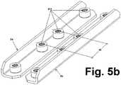
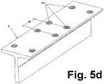
- the union plates (2)have threaded holes (241), whether made of sheet metal - figures 5a , 5b- whether it's a platinum - figure 5c -.
- the thread of the holes (241) of the union plates (2)can be made by stamping into the sheet-like on the figures 3a and 4a - or by installation of nuts originally fixed before assembly by welding or any other fastening system.
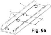
- the union plates (2)have through holes (241), whether made of sheet metal - Figures 6a , 6b - or platinum type - Figure 6c -.
- the self-centering nuts (3a)form or define a ramp head (31a) resting against the union plate (2), self-centering in its through hole (241).
- the self-aligning union system for elevator guideswhich is the subject of the invention has also provided for the use of guide tips (1) as union plates (2), used in the inverted position. .
Landscapes
- Engineering & Computer Science (AREA)
- General Engineering & Computer Science (AREA)
- Mechanical Engineering (AREA)
- Lift-Guide Devices, And Elevator Ropes And Cables (AREA)
- Cage And Drive Apparatuses For Elevators (AREA)
Description
Translated fromFrenchLa présente invention concerne un système d'union avec auto-alignement pour guides d'ascenseur.The present invention relates to a self-aligning union system for elevator guides.
L'état de la technique actuel propose déjà différents systèmes pour union alignée de guides d'ascenseur comportant des guides avec âme-champignon et ailes latérales et des plaques pour l'union de ces guides entre eux. Le demandeur lui-même a développé des systèmes de ce type et est propriétaire, entre autres, des brevets
Le document
Le problème qui se pose avec les guides unis et auto-alignés des systèmes connus consiste dans le fait que soumis à des forces (F) latérales dans les zones d'union des guides, ceux-ci se comportent comme une poutre subissant des tensions de compression du côté d'application des forces (F) et de traction du côté opposé à celui d'application de ces forces (F), et de ce fait ont tendance à se séparer par ce côté opposé et à se désaligner entre eux.The problem that arises with the plain and self-aligned guides of the known systems consists in the fact that subjected to lateral forces (F) in the union zones of the guides, these behave like a beam subjected to stress. compression on the application side of the forces (F) and traction on the opposite side to the application of these forces (F), and therefore tend to separate on the opposite side and to misalign them.
Un second problème découlant de l'auto-alignement des guides sous les systèmes connus le constitue le fait que usinages de précision sont nécessaires sur les faces latérales du guide et de la plaque d'union, c'est-à-dire, au moins deux usinages de précision indépendants.A second problem arising from the self-alignment of the guides under the known systems constitutes the fact that machining of precision are required on the lateral faces of the guide and the union plate, that is to say, at least two independent precision machining.
Les deux problèmes ont été résolus par ce brevet de la manière suivante :
- a) les surfaces frontales possèdent une finition de précision formant un angle parfait de 90° entre ces surfaces frontales par rapport à l'axe longitudinal de chaque guide ;
- b) les ailes des deux guides à unir s'unissent bout à bout, en contactant parfaitement entre elles sur toute leur surface de contact ;
- c) chaque aile possède des trous passants ;
- d) la plaque d'union possède des trous passants coïncidant avec les trous des ailes ;
- e) des moyens de rétention sont logés dans les trous des guides de la plaque ; les trous sont disposés face à face par paires et décalés entre eux une certaine distance (Δ) dans la direction de l'axe longitudinal des guides de façon qu'en y montant les moyens, une pression frontale d'alignement est créée entre les deux guides.
- a) the front surfaces have a precision finish forming a perfect 90 ° angle between these front surfaces with respect to the longitudinal axis of each guide;
- b) the wings of the two guides to be united end to end, perfectly contacting each other over their entire contact surface;
- (c) each wing has passing holes;
- d) the union plate has passing holes coinciding with the holes of the wings;
- e) retention means are housed in the holes of the guides of the plate; the holes are arranged face to face in pairs and offset between them a certain distance (Δ) in the direction of the longitudinal axis of the guides so that by mounting the means, a front alignment pressure is created between the two guides.
On remarque que le décalage (Δ) entre les trous des ailes du guide et les trous correspondants de la plaque d'union créent des forces d'union dans la direction de l'axe longitudinal du guide qui compensent les tensions de traction que peuvent produire les efforts latéraux sur les guides.Note that the offset (Δ) between the flange holes of the guide and the corresponding holes of the union plate create union forces in the direction of the longitudinal axis of the guide which compensate for the tensile stresses that can occur. lateral efforts on the guides.
On remarquera aussi qu'avec le nouveau système, un seul usinage de précision sur la surface frontale du guide est nécessaire au lieu des deux usinages de précision sur les systèmes connus.Note also that with the new system, a single precision machining on the front surface of the guide is necessary instead of the two precision machining on known systems.
Les améliorations apportées par le système d'union objet de l'invention par rapport au système connu (finition de précision de la surface frontale des ailes de chaque guide et décalage entre trous de guides et de plaque d'union pour créer une pression frontale d'alignement au montage) se traduisent par un auto-alignement des guides qui réduit le temps de montage.The improvements made by the union system object of the invention compared to the known system (precision finishing of the front surface of the wings of each guide and offset between guide holes and union plate to create a frontal pressure d 'alignment to mounting) result in self-aligning guides which reduces mounting time.
D'autre part :
- L'alignement est automatique sur les deux axes.
- l'alignement sur le axe OY se base sur :
- La précision du positionnement des trous de la plaque d'union et des trous des guides.
- La pression frontale exercée par les vis pour unir les deux guides.
- La précision de l'équerre d'usinage des extrémités par rapport au champignon du guide.
- La rigidité sur l'axe OY est très supérieure que sur le guide conventionnel du fait qu'il ne permet pas le glissement entre la plaque et le guide.
- Bien que soumis à une traction, les guides ne se séparent pas, contrairement à ce qui se passe avec les systèmes d'union de guides antérieurs.
- The alignment is automatic on both axes.
- alignment on the OY axis is based on:
- The accuracy of the positioning of the holes of the union plate and the holes of the guides.
- The frontal pressure exerted by the screws to unite the two guides.
- The precision of the machining angle of the ends with respect to the mushroom of the guide.
- The rigidity on the OY axis is much greater than on the conventional guide because it does not allow sliding between the plate and the guide.
- Although subjected to traction, the guides do not separate, unlike what happens with the previous guide union systems.
Pour mieux comprendre l'objet de la présente invention, les plans représentent une forme préférentielle de réalisation pratique, susceptible de modifications accessoires ne dénaturant pas son fondement.
- La
figure 1 est une vue générale sur plan du système d'union avec auto-alignement pour guides d'ascenseur objet de l'invention. - La
figure 2 est une vue frontale de la figure précédente. - La
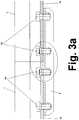
figure 3a est une section longitudinale, en détail, pour un exemple de réalisation. - La
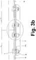
figure 3b est une section longitudinale, en détail, pour un exemple de réalisation alternative. - La
figure 4a est un détail agrandi de la zone d'union, suivant indication de lafigure 3a . - La
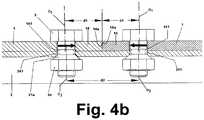
figure 4b est un détail agrandi de la zone d'union, suivant indication de lafigure 3b . - La
figure 4c est une vue sur plan de lafigure 4a , sans vis (3). - Les
figures 5a ,5b ,5c et5d sont des exemples de réalisation de la plaque d'union (2) pour la réalisation desfigures 3a et4a . - Les
figures 6a ,6b ,6c et6d sont des exemples de réalisation de la plaque d'union (2) pour la réalisation desfigures 3b et4b .
- The
figure 1 is a general plan view of the union system with self-alignment for elevator guides object of the invention. - The
figure 2 is a front view of the previous figure. - The
figure 3a is a longitudinal section, in detail, for an exemplary embodiment. - The
figure 3b is a longitudinal section, in detail, for an alternative embodiment. - The
figure 4a is an enlarged detail of the area of union, as indicated by thefigure 3a . - The
figure 4b is an enlarged detail of the area of union, as indicated by thefigure 3b . - The
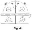
figure 4c is a plan view of thefigure 4a , without screws (3). - The
figures 5a ,5b ,5c and5d are exemplary embodiments of the union plate (2) for carrying out thefigures 3a and4a . - The
Figures 6a ,6b ,6c and6d are exemplary embodiments of the union plate (2) for carrying out thefigures 3b and4b .
Un exemple de réalisation pratique est décrit ci-dessous, non limitatif de la présente invention.An exemplary practical embodiment is described below, not limiting of the present invention.
Le système d'union avec auto-alignement pour guides d'ascenseur objet de l'invention s'utilise sur des guides (1) formés d'une âme-champignon (13) et d'une aile (14) de chaque côté.The union system with self-alignment for elevator guides object of the invention is used on guides (1) formed of a soul-mushroom (13) and a wing (14) on each side.
Les surfaces frontales (14a) des ailes (14) possèdent à l'origine une finition de précision formant un angle parfait de 90° par rapport aux surfaces latérales (12) du champignon (13) et de ce fait, au montage, les ailes (14) des deux guides (1) s'unissent bout à bout en contactant sur toute la surface frontale (14a) de leurs zones de contact.The front surfaces (14a) of the wings (14) initially have a precision finish forming a perfect angle of 90 ° with respect to the lateral surfaces (12) of the mushroom (13) and therefore, when mounting, the wings (14) of the two guides (1) are joined end to end by contacting the entire front surface (14a) of their contact areas.
Chaque aile (14) possède à l'origine des trous (141), avec axe (O1) ces trous (141) allant par paires disposées face à face : une paire ou plusieurs espacées par une distance préfixée, par exemple, la dernière des paires usinée à une distance (d1) de l'extrémité du guide (1) -
Il existe une plaque d'union (2) possédant à l'origine des trous (241), avec axe (O2) disposés par paires mises face à face et en correspondance avec les trous (141) des ailes (14) et avec au moins deux paires de ces trous (241) espacées par une distance (d2).There is a union plate (2) having originally holes (241), with axis (O2 ) arranged in pairs facing each other and in correspondence with the holes (141) of the wings (14) and with at least two pairs of these holes (241) spaced apart by a distance (d2 ).
Des moyens de rétention (3) sont logés dans les trous (141) des guides (1) et dans les trous (241) de la plaque d'union (2) dans le but de joindre fixement et solidairement la plaque d'union (2) et les ailes (14) des deux guides (1) à unir.Retention means (3) are accommodated in the holes (141) of the guides (1) and in the holes (241) of the union plate (2) for the purpose of fixedly and integrally joining the union plate ( 2) and the wings (14) of the two guides (1) to be joined.
Les trous (141), (241) mis face à face par paires sont décalés entre eux, c'est-à-dire que leurs axes (O1), (O2) sont décalés dans le sens longitudinal des guides (sur la
A partir de cette conception de base, l'objet de l'invention inclut toutes les réalisations qui n'altèrent, ne changent ou ne modifient l'essentialité proposée ; par exemple et en particulier :
- Aux effets de l'invention, il est indifférent et accessoire que la plaque d'union (2) soit en tôle ou du type platine et qu'elle soit réalisée en une seule pièce (comme sur les
figures 5a ,6a ou5c ,6c ) ou en deux pièces indépendantes (comme sur lesfigures 5b ,6b ) ; - Aux effets de l'invention il est indifférent et accessoire que la plaque d'union (2) possède des trous (241) filetés et que les moyens d'union soient des vis (3) traversant les trous (141) des guides pour se visser dans les trous (241) de la plaque d'union (2) -comme sur les
figures 3a ,4a -, ou que la plaque d'union (2) possède des trous (241) passants et que les moyens d'union soient des vis (3) traversant les deux trous (141), (241) alignés avec le décalage Δ entre eux, pour se visser (3) dans un écrou auto-centreur (3a) -comme sur lesfigures 3b ,4b -.
- To the effects of the invention, it is indifferent and incidental that the union plate (2) is made of sheet metal or of the platinum type and that it is made in one piece (as on the
figures 5a ,6a or5c ,6c ) or in two independent rooms (as infigures 5b ,6b ); - To the effects of the invention it is indifferent and incidental that the union plate (2) has threaded holes (241) and that the means of union are screws (3) passing through the holes (141) of the guides for screw into the holes (241) of the union plate (2) -as on the
figures 3a ,4a -, or that the union plate (2) has holes (241) passing and the means of union are screws (3) passing through the two holes (141), (241) aligned with the offset Δ between them , to be screwed (3) into a self-centering nut (3a) -as on thefigures 3b ,4b -.
Dans la réalisation des
Le filet des trous (241) des plaques d'union (2) peut être réalisé par emboutissage dans la tôle -comme sur les
Dans la réalisation des
Les écrous auto-centreurs (3a) forment ou définissent une tête en rampe (31a) reposant contre la plaque d'union (2), en s'auto-centrant dans son trou passant (241).The self-centering nuts (3a) form or define a ramp head (31a) resting against the union plate (2), self-centering in its through hole (241).
Dans les deux réalisations, le système d'union avec auto-alignement pour guides d'ascenseur objet de l'invention a aussi prévu l'utilisation de bouts de guide (1) comme plaques d'union (2), utilisés en position inversée.In both embodiments, the self-aligning union system for elevator guides which is the subject of the invention has also provided for the use of guide tips (1) as union plates (2), used in the inverted position. .
Dans la réalisation de la
Dans la réalisation de la
Claims (5)
- Connection system, with self-alignment, for elevator guides, the system consists of guides (1) of elevator, with a core-carriage bolt (13) and side wings (14) and connection plates (2) of said guides (1) between each other:a) the wings (14) corresponding to two guides (1) to be connected coincide fully with each other, making perfect contact in the entire front surface (14a) of its zones of contact;b) each wing (14) forms through-holes (141);c) there is a connection plate (2) that forms through-holes (241) in correspondence with the holes (141) of the wings (14);d) there are means of retention (3) lodged in said holes (141) of the guides (1) and (241) of the plate (2);characterized in that:e) the front surfaces (14a) form a precision finish keeping a perfect 90° angle between said front surfaces (14a) with respect to the longitudinal axis (e) of each guide (1) andf) the holes (141), (241) facing each other in pairs are separated from each other a certain distance (Δ) in the direction of the longitudinal axis (e) of the guides (1), so that mounting the means of retention (3) a front pressure of alignment is created between both guides (1).
- Connection system, with self-alignment, for elevator guides, according to the foregoing claim,characterized in that:a) the connection plate (2) forms through-holes (241) in correspondence with the holes (141) of the wings (14);b) there are retention screws (3) lodged in said holes (141) of the guides (1) and threaded in the holes (241) of the plate (2).
- Connection system, with self-alignment, with elevator guides, according to claim 1,characterized in that:a) the connection plate (2) forms through-holes (241) in correspondence with the holes (141) of the wings (14);b) there are retention screws (3) lodged in said holes (141), (241) and threaded in a self-centering nut (3a).
- Connection system, with self-alignment, for elevator guides, according to claim 2,characterized in that:a) the holes (141) of each wing (14) are placed opposite each other in pairs, the last of which is machined at any distance d1 from the end of the guide (1);b) the threaded holes (241) of the connection plate (2) are placed opposite each other in pairs; at least two pairs spaced between each other a distance d2;c) the holes (141), (241) opposite each other in pairs are separated from each other a certain distance of offset (Δ) verifying that 2Δ = 2d1 - d2; so that, when the screws (3) are mounted on them, a front pressure is created of alignment between both guides (1).
- Connection system, with self-alignment, for elevator guides, according to claim 3,characterized in that:a) the holes (141) of each wing (14) are placed opposite each other in pairs, the last of which is machined at any distance d1 from the end of the guide (1);b) the threaded holes (241) of the connection plate (2) are placed opposite each other in pairs; at least two pairs spaced between each other a distance d2;c) the holes (141), (241) opposite each other in pairs are separated from each other a certain distance of offset (Δ) verifying that 2Δ = 2d1 - d2; so that, when the screws are (3) installed in them and fastened with self-centering nuts (3a), front pressure of alignment between both guides (1) is created.
Applications Claiming Priority (1)
| Application Number | Priority Date | Filing Date | Title |
|---|---|---|---|
| PCT/ES2009/000181WO2010112620A1 (en) | 2009-04-02 | 2009-04-02 | Connection system, with self-alignment, for elevator guides |
Publications (3)
| Publication Number | Publication Date |
|---|---|
| EP2415703A1 EP2415703A1 (en) | 2012-02-08 |
| EP2415703A4 EP2415703A4 (en) | 2017-12-13 |
| EP2415703B1true EP2415703B1 (en) | 2018-08-08 |
Family
ID=42827500
Family Applications (1)
| Application Number | Title | Priority Date | Filing Date |
|---|---|---|---|
| EP09842540.8AActiveEP2415703B1 (en) | 2009-04-02 | 2009-04-02 | Connection system, with self-alignment, for elevator guides |
Country Status (7)
| Country | Link |
|---|---|
| US (1) | US8939264B2 (en) |
| EP (1) | EP2415703B1 (en) |
| CN (1) | CN102341334B (en) |
| BR (1) | BRPI0925060A2 (en) |
| ES (1) | ES2686907T3 (en) |
| TR (1) | TR201815632T4 (en) |
| WO (1) | WO2010112620A1 (en) |
Families Citing this family (4)
| Publication number | Priority date | Publication date | Assignee | Title |
|---|---|---|---|---|
| FI125131B (en)* | 2012-04-10 | 2015-06-15 | Kone Corp | Joints for lift guides, joint arrangements for lift guides and lift |
| US10906779B2 (en)* | 2016-12-07 | 2021-02-02 | Inventio Ag | Rail foot holder for fastening a rail of an elevator system |
| CN107825131A (en)* | 2017-10-10 | 2018-03-23 | 温州大学 | A kind of pipeline centering device and its application method |
| CN114108393A (en)* | 2021-12-06 | 2022-03-01 | 姜世文 | Rail bottom connection of steel rail and its application |
Family Cites Families (23)
| Publication number | Priority date | Publication date | Assignee | Title |
|---|---|---|---|---|
| US1720202A (en)* | 1928-06-06 | 1929-07-09 | Union Drawn Steel Company | Guide rail |
| US3252495A (en) | 1959-02-18 | 1966-05-24 | Lamson & Sessions Co | Bolt with a knurled barrel-shaped shank |
| US3640328A (en)* | 1970-08-12 | 1972-02-08 | Natale J Tummarello | Means for mounting concrete structural members |
| GB2150960A (en)* | 1983-11-22 | 1985-07-10 | Underground Mining Mach | Rail joint |
| JP2513802B2 (en)* | 1988-09-08 | 1996-07-03 | 株式会社東芝 | Auxiliary device for lifting elevator guide rails |
| ES2047651T3 (en)* | 1989-02-10 | 1994-03-01 | Inventio Ag | DEVICE TO JOIN GUIDE RAILS. |
| DE4110185C1 (en)* | 1991-03-25 | 1992-08-06 | Mannesmann Ag, 4000 Duesseldorf, De | |
| JP3488550B2 (en)* | 1995-09-20 | 2004-01-19 | 東芝エレベータ株式会社 | Elevator guide rail connection device |
| JPH10297842A (en)* | 1997-04-22 | 1998-11-10 | Otis Elevator Co | Butt strap for guide rail of elevator |
| US6413005B1 (en)* | 1999-03-23 | 2002-07-02 | Wahoo Concrete Products, Inc. | Fastener having a self-centering and self-aligning capability for one-sided insertion and tightening on a slat floor |
| CN1185161C (en)* | 1999-12-23 | 2005-01-19 | S.A.德贝拉(萨贝拉)公司 | Elevator guide assembly system |
| DE10139271A1 (en)* | 2001-08-09 | 2003-02-27 | Boegl Max Bauunternehmung Gmbh | Track for a track-bound vehicle |
| WO2003048456A1 (en)* | 2001-12-07 | 2003-06-12 | Kevin Francis Edsall | A rail separator and method of separating a pair of rails |
| US6830133B2 (en)* | 2002-03-06 | 2004-12-14 | Terryle L. Sneed | Connector brackets |
| US20040195049A1 (en)* | 2003-03-18 | 2004-10-07 | Alexander Stobo | Cab construction |
| ES2255351B1 (en)* | 2003-07-10 | 2007-07-16 | S.A. De Vera (Savera) | SELF-ALIGNED UNION SYSTEM, FOR HIGH SPEED ELEVATOR GUIDES. |
| DE60329286D1 (en)* | 2003-07-15 | 2009-10-29 | Monteferro S P A | Positioning device for the guide rails of elevators |
| KR20060129268A (en)* | 2004-01-26 | 2006-12-15 | 에스.에이. 데 베라 (사베라) | Quick connection / assembly system for lift guides |
| ES2238918B1 (en)* | 2004-01-26 | 2006-11-01 | S.A. De Vera (Savera) | FAST UNION / ASSEMBLY SYSTEM, FOR ELEVATOR GUIDES. |
| CN1895982B (en)* | 2005-07-13 | 2011-06-15 | 因温特奥股份公司 | Connecting element |
| EP1743863A1 (en)* | 2005-07-13 | 2007-01-17 | Inventio Ag | Connecting element |
| ES2320949B1 (en)* | 2006-11-16 | 2010-03-09 | S.A. De Vera (Savera) | UNION SYSTEM WITH SELF-ALIGNED, FOR ELEVATOR GUIDES. |
| ES2400662B1 (en)* | 2011-04-18 | 2014-09-23 | S.A. De Vera (Savera) | SELF-ALIGNING UNION, FOR ELEVATOR GUIDES |
- 2009
- 2009-04-02EPEP09842540.8Apatent/EP2415703B1/enactiveActive
- 2009-04-02USUS13/148,729patent/US8939264B2/enactiveActive
- 2009-04-02CNCN200980157722.5Apatent/CN102341334B/enactiveActive
- 2009-04-02WOPCT/ES2009/000181patent/WO2010112620A1/enactiveApplication Filing
- 2009-04-02BRBRPI0925060-3Apatent/BRPI0925060A2/ennot_activeIP Right Cessation
- 2009-04-02ESES09842540.8Tpatent/ES2686907T3/enactiveActive
- 2009-04-02TRTR2018/15632Tpatent/TR201815632T4/enunknown
Non-Patent Citations (1)
| Title |
|---|
| None* |
Also Published As
| Publication number | Publication date |
|---|---|
| US20110309156A1 (en) | 2011-12-22 |
| EP2415703A4 (en) | 2017-12-13 |
| CN102341334A (en) | 2012-02-01 |
| TR201815632T4 (en) | 2018-11-21 |
| US8939264B2 (en) | 2015-01-27 |
| CN102341334B (en) | 2014-08-20 |
| BRPI0925060A2 (en) | 2015-07-28 |
| WO2010112620A1 (en) | 2010-10-07 |
| EP2415703A1 (en) | 2012-02-08 |
| ES2686907T3 (en) | 2018-10-22 |
Similar Documents
| Publication | Publication Date | Title |
|---|---|---|
| EP2415703B1 (en) | Connection system, with self-alignment, for elevator guides | |
| FR3058743A1 (en) | ARRANGEMENT FOR FIXING A PANEL INTO A GROOVE USING TWO OPPOSITE CORNERS | |
| FR2739408A1 (en) | WINDOW REGULATOR FOR VEHICLE DOOR | |
| US20190039413A1 (en) | Axle unit | |
| EP3298286B1 (en) | Improved fastening element | |
| WO2009077702A1 (en) | Crossbar for dashboard of an automobile and automobile including such crossbar | |
| FR2733174A1 (en) | BLOCKING DEVICE FOR BLADE OF CHIP MACHINE | |
| WO2011077021A1 (en) | Device for attaching a plate against a flat face of a fixed motor vehicle component | |
| FR2797407A1 (en) | LOWER APRON PRESS WITH SLOTS | |
| EP1830073B1 (en) | Device for attaching two pieces, one pinned against the other, using a clip | |
| CH700557A2 (en) | bending press for bending sheets. | |
| EP3684635B1 (en) | Cross-member system for a motor vehicle receiving a transverse guide bar | |
| EP1712511B1 (en) | Quick-coupling/mounting system for elevator guides | |
| EP2572962B1 (en) | Attachment assembly for steering column | |
| FR2604230A1 (en) | AUTOMATIC ADJUSTMENT SPACER FOR DRUM BRAKE AND BLANK FOR REALIZING THE BODY OF SUCH A SPACER. | |
| FR3003805A1 (en) | MOTOR VEHICLE ANTI-DEVICE BAR BEARING, COMPRISING A FLANGE WITH AN EXTENDED DRILL | |
| FR2833630A1 (en) | Wooden crash barrier comprises log with square mortise receiving rigidifying support element which receives connecting sleeve at each end engaging element of another log | |
| WO2014154968A1 (en) | Bearing for fixing a stabiliser bar to the chassis of a motor vehicle | |
| WO2020161133A1 (en) | Reinforced rear structure part of a motor vehicle | |
| EP3715259B1 (en) | Assembly for an aircraft, the assembly comprising a mast, an engine mount and an attachment system between the mast and the engine mount | |
| WO2003020547A1 (en) | Device for fixing a rail to a motor vehicle floor pan and the method using said device | |
| EP2022704A1 (en) | Means for linking two mechanical parts of the structure of an automobile | |
| EP3668732B1 (en) | Motor vehicle cross member system having inserts for a transverse guide bar | |
| FR2842767A1 (en) | Runner for vehicle seat comprises fixed section and movable transverse U-section with two vertical webs, seat fixing screw with widened head engages vertical web which has head retaining part | |
| EP1480863B1 (en) | Device for fixing a connecting crossbar to a shoe brake for a rail bogie |
Legal Events
| Date | Code | Title | Description |
|---|---|---|---|
| PUAI | Public reference made under article 153(3) epc to a published international application that has entered the european phase | Free format text:ORIGINAL CODE: 0009012 | |
| 17P | Request for examination filed | Effective date:20111102 | |
| AK | Designated contracting states | Kind code of ref document:A1 Designated state(s):AT BE BG CH CY CZ DE DK EE ES FI FR GB GR HR HU IE IS IT LI LT LU LV MC MK MT NL NO PL PT RO SE SI SK TR | |
| RIN1 | Information on inventor provided before grant (corrected) | Inventor name:SANZ GAMBOA, JESUS | |
| RIN1 | Information on inventor provided before grant (corrected) | Inventor name:SANZ GAMBOA, JESUS | |
| DAX | Request for extension of the european patent (deleted) | ||
| RA4 | Supplementary search report drawn up and despatched (corrected) | Effective date:20171110 | |
| RIC1 | Information provided on ipc code assigned before grant | Ipc:B66B 7/02 20060101AFI20171106BHEP | |
| GRAP | Despatch of communication of intention to grant a patent | Free format text:ORIGINAL CODE: EPIDOSNIGR1 | |
| STAA | Information on the status of an ep patent application or granted ep patent | Free format text:STATUS: GRANT OF PATENT IS INTENDED | |
| GRAS | Grant fee paid | Free format text:ORIGINAL CODE: EPIDOSNIGR3 | |
| GRAA | (expected) grant | Free format text:ORIGINAL CODE: 0009210 | |
| STAA | Information on the status of an ep patent application or granted ep patent | Free format text:STATUS: THE PATENT HAS BEEN GRANTED | |
| INTG | Intention to grant announced | Effective date:20180614 | |
| AK | Designated contracting states | Kind code of ref document:B1 Designated state(s):AT BE BG CH CY CZ DE DK EE ES FI FR GB GR HR HU IE IS IT LI LT LU LV MC MK MT NL NO PL PT RO SE SI SK TR | |
| REG | Reference to a national code | Ref country code:GB Ref legal event code:FG4D | |
| REG | Reference to a national code | Ref country code:CH Ref legal event code:EP Ref country code:AT Ref legal event code:REF Ref document number:1026723 Country of ref document:AT Kind code of ref document:T Effective date:20180815 | |
| REG | Reference to a national code | Ref country code:IE Ref legal event code:FG4D Free format text:LANGUAGE OF EP DOCUMENT: FRENCH | |
| REG | Reference to a national code | Ref country code:DE Ref legal event code:R096 Ref document number:602009053806 Country of ref document:DE | |
| REG | Reference to a national code | Ref country code:ES Ref legal event code:FG2A Ref document number:2686907 Country of ref document:ES Kind code of ref document:T3 Effective date:20181022 | |
| REG | Reference to a national code | Ref country code:NL Ref legal event code:MP Effective date:20180808 | |
| REG | Reference to a national code | Ref country code:LT Ref legal event code:MG4D | |
| REG | Reference to a national code | Ref country code:AT Ref legal event code:MK05 Ref document number:1026723 Country of ref document:AT Kind code of ref document:T Effective date:20180808 | |
| PG25 | Lapsed in a contracting state [announced via postgrant information from national office to epo] | Ref country code:BG Free format text:LAPSE BECAUSE OF FAILURE TO SUBMIT A TRANSLATION OF THE DESCRIPTION OR TO PAY THE FEE WITHIN THE PRESCRIBED TIME-LIMIT Effective date:20181108 Ref country code:NL Free format text:LAPSE BECAUSE OF FAILURE TO SUBMIT A TRANSLATION OF THE DESCRIPTION OR TO PAY THE FEE WITHIN THE PRESCRIBED TIME-LIMIT Effective date:20180808 Ref country code:LT Free format text:LAPSE BECAUSE OF FAILURE TO SUBMIT A TRANSLATION OF THE DESCRIPTION OR TO PAY THE FEE WITHIN THE PRESCRIBED TIME-LIMIT Effective date:20180808 Ref country code:PL Free format text:LAPSE BECAUSE OF FAILURE TO SUBMIT A TRANSLATION OF THE DESCRIPTION OR TO PAY THE FEE WITHIN THE PRESCRIBED TIME-LIMIT Effective date:20180808 Ref country code:IS Free format text:LAPSE BECAUSE OF FAILURE TO SUBMIT A TRANSLATION OF THE DESCRIPTION OR TO PAY THE FEE WITHIN THE PRESCRIBED TIME-LIMIT Effective date:20181208 Ref country code:AT Free format text:LAPSE BECAUSE OF FAILURE TO SUBMIT A TRANSLATION OF THE DESCRIPTION OR TO PAY THE FEE WITHIN THE PRESCRIBED TIME-LIMIT Effective date:20180808 Ref country code:GR Free format text:LAPSE BECAUSE OF FAILURE TO SUBMIT A TRANSLATION OF THE DESCRIPTION OR TO PAY THE FEE WITHIN THE PRESCRIBED TIME-LIMIT Effective date:20181109 Ref country code:NO Free format text:LAPSE BECAUSE OF FAILURE TO SUBMIT A TRANSLATION OF THE DESCRIPTION OR TO PAY THE FEE WITHIN THE PRESCRIBED TIME-LIMIT Effective date:20181108 Ref country code:SE Free format text:LAPSE BECAUSE OF FAILURE TO SUBMIT A TRANSLATION OF THE DESCRIPTION OR TO PAY THE FEE WITHIN THE PRESCRIBED TIME-LIMIT Effective date:20180808 Ref country code:FI Free format text:LAPSE BECAUSE OF FAILURE TO SUBMIT A TRANSLATION OF THE DESCRIPTION OR TO PAY THE FEE WITHIN THE PRESCRIBED TIME-LIMIT Effective date:20180808 | |
| PG25 | Lapsed in a contracting state [announced via postgrant information from national office to epo] | Ref country code:HR Free format text:LAPSE BECAUSE OF FAILURE TO SUBMIT A TRANSLATION OF THE DESCRIPTION OR TO PAY THE FEE WITHIN THE PRESCRIBED TIME-LIMIT Effective date:20180808 Ref country code:LV Free format text:LAPSE BECAUSE OF FAILURE TO SUBMIT A TRANSLATION OF THE DESCRIPTION OR TO PAY THE FEE WITHIN THE PRESCRIBED TIME-LIMIT Effective date:20180808 | |
| PG25 | Lapsed in a contracting state [announced via postgrant information from national office to epo] | Ref country code:EE Free format text:LAPSE BECAUSE OF FAILURE TO SUBMIT A TRANSLATION OF THE DESCRIPTION OR TO PAY THE FEE WITHIN THE PRESCRIBED TIME-LIMIT Effective date:20180808 Ref country code:RO Free format text:LAPSE BECAUSE OF FAILURE TO SUBMIT A TRANSLATION OF THE DESCRIPTION OR TO PAY THE FEE WITHIN THE PRESCRIBED TIME-LIMIT Effective date:20180808 | |
| REG | Reference to a national code | Ref country code:DE Ref legal event code:R097 Ref document number:602009053806 Country of ref document:DE | |
| PG25 | Lapsed in a contracting state [announced via postgrant information from national office to epo] | Ref country code:SK Free format text:LAPSE BECAUSE OF FAILURE TO SUBMIT A TRANSLATION OF THE DESCRIPTION OR TO PAY THE FEE WITHIN THE PRESCRIBED TIME-LIMIT Effective date:20180808 Ref country code:DK Free format text:LAPSE BECAUSE OF FAILURE TO SUBMIT A TRANSLATION OF THE DESCRIPTION OR TO PAY THE FEE WITHIN THE PRESCRIBED TIME-LIMIT Effective date:20180808 | |
| PLBE | No opposition filed within time limit | Free format text:ORIGINAL CODE: 0009261 | |
| STAA | Information on the status of an ep patent application or granted ep patent | Free format text:STATUS: NO OPPOSITION FILED WITHIN TIME LIMIT | |
| 26N | No opposition filed | Effective date:20190509 | |
| PG25 | Lapsed in a contracting state [announced via postgrant information from national office to epo] | Ref country code:SI Free format text:LAPSE BECAUSE OF FAILURE TO SUBMIT A TRANSLATION OF THE DESCRIPTION OR TO PAY THE FEE WITHIN THE PRESCRIBED TIME-LIMIT Effective date:20180808 | |
| REG | Reference to a national code | Ref country code:CH Ref legal event code:PL | |
| REG | Reference to a national code | Ref country code:BE Ref legal event code:MM Effective date:20190430 | |
| GBPC | Gb: european patent ceased through non-payment of renewal fee | Effective date:20190402 | |
| PG25 | Lapsed in a contracting state [announced via postgrant information from national office to epo] | Ref country code:MC Free format text:LAPSE BECAUSE OF FAILURE TO SUBMIT A TRANSLATION OF THE DESCRIPTION OR TO PAY THE FEE WITHIN THE PRESCRIBED TIME-LIMIT Effective date:20180808 Ref country code:LU Free format text:LAPSE BECAUSE OF NON-PAYMENT OF DUE FEES Effective date:20190402 | |
| PG25 | Lapsed in a contracting state [announced via postgrant information from national office to epo] | Ref country code:CH Free format text:LAPSE BECAUSE OF NON-PAYMENT OF DUE FEES Effective date:20190430 Ref country code:GB Free format text:LAPSE BECAUSE OF NON-PAYMENT OF DUE FEES Effective date:20190402 Ref country code:LI Free format text:LAPSE BECAUSE OF NON-PAYMENT OF DUE FEES Effective date:20190430 | |
| PG25 | Lapsed in a contracting state [announced via postgrant information from national office to epo] | Ref country code:BE Free format text:LAPSE BECAUSE OF NON-PAYMENT OF DUE FEES Effective date:20190430 | |
| PG25 | Lapsed in a contracting state [announced via postgrant information from national office to epo] | Ref country code:IE Free format text:LAPSE BECAUSE OF NON-PAYMENT OF DUE FEES Effective date:20190402 | |
| PG25 | Lapsed in a contracting state [announced via postgrant information from national office to epo] | Ref country code:FR Free format text:LAPSE BECAUSE OF NON-PAYMENT OF DUE FEES Effective date:20190430 Ref country code:PT Free format text:LAPSE BECAUSE OF FAILURE TO SUBMIT A TRANSLATION OF THE DESCRIPTION OR TO PAY THE FEE WITHIN THE PRESCRIBED TIME-LIMIT Effective date:20181208 | |
| REG | Reference to a national code | Ref country code:DE Ref legal event code:R082 Ref document number:602009053806 Country of ref document:DE Representative=s name:DEHNS GERMANY PARTNERSCHAFT MBB, DE Ref country code:DE Ref legal event code:R082 Ref document number:602009053806 Country of ref document:DE Representative=s name:DEHNSGERMANY PARTNERSCHAFT VON PATENTANWAELTEN, DE | |
| PG25 | Lapsed in a contracting state [announced via postgrant information from national office to epo] | Ref country code:CY Free format text:LAPSE BECAUSE OF FAILURE TO SUBMIT A TRANSLATION OF THE DESCRIPTION OR TO PAY THE FEE WITHIN THE PRESCRIBED TIME-LIMIT Effective date:20180808 | |
| PG25 | Lapsed in a contracting state [announced via postgrant information from national office to epo] | Ref country code:MT Free format text:LAPSE BECAUSE OF FAILURE TO SUBMIT A TRANSLATION OF THE DESCRIPTION OR TO PAY THE FEE WITHIN THE PRESCRIBED TIME-LIMIT Effective date:20180808 Ref country code:HU Free format text:LAPSE BECAUSE OF FAILURE TO SUBMIT A TRANSLATION OF THE DESCRIPTION OR TO PAY THE FEE WITHIN THE PRESCRIBED TIME-LIMIT; INVALID AB INITIO Effective date:20090402 | |
| PG25 | Lapsed in a contracting state [announced via postgrant information from national office to epo] | Ref country code:MK Free format text:LAPSE BECAUSE OF FAILURE TO SUBMIT A TRANSLATION OF THE DESCRIPTION OR TO PAY THE FEE WITHIN THE PRESCRIBED TIME-LIMIT Effective date:20180808 | |
| PG25 | Lapsed in a contracting state [announced via postgrant information from national office to epo] | Ref country code:IT Free format text:LAPSE BECAUSE OF NON-PAYMENT OF DUE FEES Effective date:20220402 | |
| PGFP | Annual fee paid to national office [announced via postgrant information from national office to epo] | Ref country code:CZ Payment date:20250320 Year of fee payment:17 | |
| PGFP | Annual fee paid to national office [announced via postgrant information from national office to epo] | Ref country code:TR Payment date:20250324 Year of fee payment:17 | |
| PGFP | Annual fee paid to national office [announced via postgrant information from national office to epo] | Ref country code:DE Payment date:20250423 Year of fee payment:17 | |
| PGFP | Annual fee paid to national office [announced via postgrant information from national office to epo] | Ref country code:ES Payment date:20250506 Year of fee payment:17 | |
| PGFP | Annual fee paid to national office [announced via postgrant information from national office to epo] | Ref country code:IT Payment date:20250402 Year of fee payment:17 |