EP2414233B1 - Passenger seat with single actuator seat mechanism - Google Patents
Passenger seat with single actuator seat mechanismDownload PDFInfo
- Publication number
- EP2414233B1 EP2414233B1EP10713086.6AEP10713086AEP2414233B1EP 2414233 B1EP2414233 B1EP 2414233B1EP 10713086 AEP10713086 AEP 10713086AEP 2414233 B1EP2414233 B1EP 2414233B1
- Authority
- EP
- European Patent Office
- Prior art keywords
- seat
- leg rest
- pivotally attached
- actuator
- seat back
- Prior art date
- Legal status (The legal status is an assumption and is not a legal conclusion. Google has not performed a legal analysis and makes no representation as to the accuracy of the status listed.)
- Not-in-force
Links
- 230000007246mechanismEffects0.000titledescription6
- 238000000034methodMethods0.000claimsdescription8
- 230000033001locomotionEffects0.000claimsdescription6
- 230000000712assemblyEffects0.000description3
- 238000000429assemblyMethods0.000description3
- 230000010006flightEffects0.000description1
- 239000000446fuelSubstances0.000description1
- 238000012423maintenanceMethods0.000description1
- 238000012986modificationMethods0.000description1
- 230000004048modificationEffects0.000description1
- 230000000284resting effectEffects0.000description1
Images


Classifications
- B—PERFORMING OPERATIONS; TRANSPORTING
- B64—AIRCRAFT; AVIATION; COSMONAUTICS
- B64D—EQUIPMENT FOR FITTING IN OR TO AIRCRAFT; FLIGHT SUITS; PARACHUTES; ARRANGEMENT OR MOUNTING OF POWER PLANTS OR PROPULSION TRANSMISSIONS IN AIRCRAFT
- B64D11/00—Passenger or crew accommodation; Flight-deck installations not otherwise provided for
- B64D11/06—Arrangements of seats, or adaptations or details specially adapted for aircraft seats
- B64D11/0639—Arrangements of seats, or adaptations or details specially adapted for aircraft seats with features for adjustment or converting of seats
- B64D11/064—Adjustable inclination or position of seats
- B—PERFORMING OPERATIONS; TRANSPORTING
- B60—VEHICLES IN GENERAL
- B60N—SEATS SPECIALLY ADAPTED FOR VEHICLES; VEHICLE PASSENGER ACCOMMODATION NOT OTHERWISE PROVIDED FOR
- B60N2/00—Seats specially adapted for vehicles; Arrangement or mounting of seats in vehicles
- B60N2/90—Details or parts not otherwise provided for
- B60N2/995—Lower-leg-rests, e.g. calf-rests
- B—PERFORMING OPERATIONS; TRANSPORTING
- B64—AIRCRAFT; AVIATION; COSMONAUTICS
- B64D—EQUIPMENT FOR FITTING IN OR TO AIRCRAFT; FLIGHT SUITS; PARACHUTES; ARRANGEMENT OR MOUNTING OF POWER PLANTS OR PROPULSION TRANSMISSIONS IN AIRCRAFT
- B64D11/00—Passenger or crew accommodation; Flight-deck installations not otherwise provided for
- B64D11/06—Arrangements of seats, or adaptations or details specially adapted for aircraft seats
- B64D11/0639—Arrangements of seats, or adaptations or details specially adapted for aircraft seats with features for adjustment or converting of seats
- B64D11/06395—Arrangements of seats, or adaptations or details specially adapted for aircraft seats with features for adjustment or converting of seats characterised by the arrangement of electric motors for adjustment
- B—PERFORMING OPERATIONS; TRANSPORTING
- B64—AIRCRAFT; AVIATION; COSMONAUTICS
- B64D—EQUIPMENT FOR FITTING IN OR TO AIRCRAFT; FLIGHT SUITS; PARACHUTES; ARRANGEMENT OR MOUNTING OF POWER PLANTS OR PROPULSION TRANSMISSIONS IN AIRCRAFT
- B64D11/00—Passenger or crew accommodation; Flight-deck installations not otherwise provided for
- B64D11/06—Arrangements of seats, or adaptations or details specially adapted for aircraft seats
- B64D11/0639—Arrangements of seats, or adaptations or details specially adapted for aircraft seats with features for adjustment or converting of seats
- B64D11/0643—Adjustable foot or leg rests
Definitions
- This inventionrelates generally to a reclining passenger seat, and more particularly to a passenger seat having a leg rest, seat pan, and seat back that are adjusted by a single powered actuator.
- a passenger seatincludes the measures of claim 1.
- the passenger seatincludes a y-shaped yoke having three pivotal attachment points by which the yoke is pivotally attached to the rigid frame, linked to the actuator, and linked to the leg rest, respectively.
- the passenger seatincludes a leg rest support link having a first end pivotally attached to the yoke and a second end pivotally attached to the leg rest such that the leg rest support link forces the leg rest to pivot forward as the actuator extends.
- the passenger seatincludes a lever rigidly attached to the seat back and pivotally attached to the rearward end of claim the seat pan such that the lever forces the lower end of the seat back to move forward with the seat pan as the actuator extends.
- the passenger seatincludes a seat back link having a first end pivotally attached to the lever and a second end pivotally attached to a rearward end of the rigid frame such that the lower end of seat back moves forward as the actuator extends.
- the actuatoris an electrically powered linear actuator.
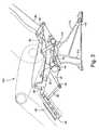
- FIG. 1is a side elevation view of a passenger seat according to at least one embodiment of the invention, shown in an upright TTL configuration;
- FIG. 2is a side elevation view of the passenger seat of FIG. 1 , shown in a partially reclined configuration
- FIG. 3is a side elevation view of the passenger seat of FIG. 1 , shown in a maximally reclined configuration.
- the passenger seat 100includes a deployment mechanism 10 that coordinates movements of the seat pan 20, leg rest 30, and seat back 40 as the passenger seat is adjusted from the upright configuration of FIG. 1 , through the partially reclined configuration of FIG. 2 , to the maximally reclined configuration of FIG. 3 .
- the deployment mechanism 10is driven by a single linear actuator 12 that forcibly extends to drive the passenger seat toward the maximally reclined configuration of FIG. 3 and withdraws as the seat 100 is returned to the upright configuration of FIG.1 , which corresponds to the preferred configuration during the taxi, take-off, and landing (TTL) procedures of an aircraft.
- the linear actuator 12in one particular example is an electrically powered actuator controlled by one or more buttons available to a seated passenger or vehicle crew members.
- the actuator 12may be controlled by dedicated manual buttons or may be controlled by virtual buttons on a touchpad seating control interface device.
- the passenger seat 100is supported by a rigid frame 110 having upright leg assemblies 112 and tubular horizontal beams 114. Only one leg assembly 112 is illustrated in the drawings but it should be understood that any number of leg assemblies 112 can be arranged in a seating row to support one or multiple passenger seats 100.
- the horizontal beams 114can extend to any preferred length, connecting adjacent leg assemblies 112 in a seating row.
- the leg 112has a lower forward end 114 and lower rearward end 116 that terminate in respective anchors 118 by which the passenger seat 100 is secured to the deck of an aircraft or other vehicle.
- the rigid frame 110may be considered as stationary with respect to the deck of a vehicle as the vehicle travels.
- a leg rest drive link 14is pivotally attached at its rearward end to the linear actuator 12 and at its forward end to a y-shaped leg rest pivot yoke 32, which is pivotally attached to the forward end of the frame 110 by a pin 122.
- the actuator 12is pivotally connected at opposing ends thereof to the rigid frame 110 and the drive link 14.
- the drive link 14forces the yoke 32 to pivot about the pin 122, thereby extending the distal end 34 of the yoke from the stowed TTL position of FIG. 1 to the deployed configuration of FIG. 3 , as the actuator 12 extends to adjust the seat 100 toward the reclined configuration.
- the leg rest 30is pivotally attached at its upper end 38 to the forward end of the seat pan 20, and is carried generally forward and upward as the seat pan travels from the TTL position of FIG. 1 to the reclined position of FIG. 3 .
- a leg support link 36is pivotally attached at its opposing ends to the distal end 34 of the yoke and the leg rest 30 respectively.
- the leg rest 30is deployed by the leg support link 36 toward a leg supporting position by pivoting about the forward end of the seat pan 20.
- the angle of the leg rest 30 with respect to horizontalreaches approximately 30 degrees in one particular example.
- the resulting angle of the leg rest 30 with respect to horizontalmay be customized by adjusting either the length of the leg rest support link 36 or the position at which the leg rest support link attaches to leg rest 30.
- the leg rest support link 36may either be shortened or attached closer to the floor.
- a deployable footrest 50is pivotally attached to the distal end of the leg rest 30 for extending the length of the leg rest 30 and supporting the feet of a passenger.
- the footrest 50may be a selectively deployed by the seat occupant, or may be automatically deployed as the seat 100 is adjusted from the TTL configuration to a reclined configuration.
- the seat pan 20is pulled forward by the upper end 38 of the leg rest 30. Movement of the seat pan 20 is guided by a seat pan link 26 and a roller that bears upon the lower surface of the seat pan.
- the seat pan link 26guides the seat pan 20 forward, by approximately 4 inches in one particular example, with respect to the stationary frame 110. In moving from its TTL position in FIG. 1 to its maximally reclined position in FIG. 3 , the seat pan moves forward overall, with its forward end raising and its rearward end lowering for the comfort of a seated passenger.
- An angled lever 42defines a lower portion of the seat back 40.
- the forward lower end of the lever 42is pivotally attached to a rearward portion of the seat pan 20 and travels with the movement of the seat pan.
- a seat back link 44has a first end pivotally attached to the lever 42 and a second end pivotally attached to the rearward and upper end of the stationary frame 110. The forward movement of the seat pan 20 in turn causes the lever 42 to move forward. With the seat back 40 guided by the seat back link 44 and moved under the forces applied by the lever 42 as the seat 100 is adjusted from the TTL configuration of FIG. 1 to the maximally reclined configuration of FIG. 3 , the lower end of the seat back 40 moves forward and downward. The upper end of the seat back 40 travels downward and rearward.
- the upper end of the seat back 40travels approximately 4-5 inches.
- the seat back 40overall leans back as the maximally reclined configuration of FIG. 3 is approached.
- the seat back 40maximally reclines approximately 20 degrees from its TTL configuration and approximately 41 degrees from vertical.
- the deployment mechanism 10 of the present inventionprovides a greater recline angle in the same amount of space as compared to conventional seat mechanisms.
Landscapes
- Engineering & Computer Science (AREA)
- Aviation & Aerospace Engineering (AREA)
- Transportation (AREA)
- Mechanical Engineering (AREA)
- Seats For Vehicles (AREA)
- Chairs For Special Purposes, Such As Reclining Chairs (AREA)
- Passenger Equipment (AREA)
Description
- This invention relates generally to a reclining passenger seat, and more particularly to a passenger seat having a leg rest, seat pan, and seat back that are adjusted by a single powered actuator.
- Long-haul aircraft flights regularly fly non-stop to destinations 12-18 hours or more away from the origination point. At present, aircraft cabins provide various forms of reclining seats so that passengers are able to attain comfortable resting positions. Seat backs that simply recline by hinging back consume considerable space in the passenger cabin. Space in a passenger cabin is a limited resource in any craft, and is a particularly critical resource in a passenger aircraft due to fuel costs and price competition among airlines. A typical passenger desires both a low cost in flying and a comfortable experience.
- The cost and complexity of a passenger seat is also a concern for aircraft operators because the expenses of purchasing, installing, and maintaining each piece of equipment on an aircraft affect the economic success of each For example, where a seat has several adjustable components, several powered actuators might be dedicated to the components and each actuator would represent an expense in the purchase and maintenance of the seat. The document
us 2004/080201 discloses a seat according to the preamble of claim 1. - Accordingly, there is a need for a passenger seat having a single actuator adjustment mechanism.
- According to at least one embodiment of the invention, a passenger seat includes the measures of claim 1.
- According to at least one embodiment, the passenger seat includes a y-shaped yoke having three pivotal attachment points by which the yoke is pivotally attached to the rigid frame, linked to the actuator, and linked to the leg rest, respectively.
- According to at least one embodiment, the passenger seat includes a leg rest support link having a first end pivotally attached to the yoke and a second end pivotally attached to the leg rest such that the leg rest support link forces the leg rest to pivot forward as the actuator extends.
- According to at least one embodiment, the passenger seat includes a lever rigidly attached to the seat back and pivotally attached to the rearward end of claim the seat pan such that the lever forces the lower end of the seat back to move forward with the seat pan as the actuator extends.
- According to at least one embodiment, the passenger seat includes a seat back link having a first end pivotally attached to the lever and a second end pivotally attached to a rearward end of the rigid frame such that the lower end of seat back moves forward as the actuator extends.
- According to at least one embodiment, the actuator is an electrically powered linear actuator.
- According to at least one embodiment of the invention relates to a method of adjusting a passenger according to claim 7.
- The subject matter that is regarded as the Invention may be best understood by reference to the following description taken in conjunction with the accompanying drawing figures In which:
FIG. 1 is a side elevation view of a passenger seat according to at least one embodiment of the invention, shown in an upright TTL configuration;FIG. 2 is a side elevation view of the passenger seat ofFIG. 1 , shown in a partially reclined configuration; andFIG. 3 is a side elevation view of the passenger seat ofFIG. 1 , shown in a maximally reclined configuration.- As shown in
FIGS. 1-3 , thepassenger seat 100 includes adeployment mechanism 10 that coordinates movements of theseat pan 20,leg rest 30, and seat back 40 as the passenger seat is adjusted from the upright configuration ofFIG. 1 , through the partially reclined configuration ofFIG. 2 , to the maximally reclined configuration ofFIG. 3 . Thedeployment mechanism 10 is driven by a singlelinear actuator 12 that forcibly extends to drive the passenger seat toward the maximally reclined configuration ofFIG. 3 and withdraws as theseat 100 is returned to the upright configuration ofFIG.1 , which corresponds to the preferred configuration during the taxi, take-off, and landing (TTL) procedures of an aircraft. Thelinear actuator 12 in one particular example is an electrically powered actuator controlled by one or more buttons available to a seated passenger or vehicle crew members. Theactuator 12 may be controlled by dedicated manual buttons or may be controlled by virtual buttons on a touchpad seating control interface device. - The
passenger seat 100 is supported by arigid frame 110 havingupright leg assemblies 112 and tubularhorizontal beams 114. Only oneleg assembly 112 is illustrated in the drawings but it should be understood that any number ofleg assemblies 112 can be arranged in a seating row to support one ormultiple passenger seats 100. Thehorizontal beams 114 can extend to any preferred length, connectingadjacent leg assemblies 112 in a seating row. Theleg 112 has a lowerforward end 114 and lower rearwardend 116 that terminate inrespective anchors 118 by which thepassenger seat 100 is secured to the deck of an aircraft or other vehicle. Thus, therigid frame 110 may be considered as stationary with respect to the deck of a vehicle as the vehicle travels. - A leg
rest drive link 14 is pivotally attached at its rearward end to thelinear actuator 12 and at its forward end to a y-shaped legrest pivot yoke 32, which is pivotally attached to the forward end of theframe 110 by apin 122. Thus theyoke 32 is constrained to pivot about thepin 122 relative to the frame. Theactuator 12 is pivotally connected at opposing ends thereof to therigid frame 110 and thedrive link 14. Thedrive link 14 forces theyoke 32 to pivot about thepin 122, thereby extending thedistal end 34 of the yoke from the stowed TTL position ofFIG. 1 to the deployed configuration ofFIG. 3 , as theactuator 12 extends to adjust theseat 100 toward the reclined configuration. Theleg rest 30 is pivotally attached at itsupper end 38 to the forward end of theseat pan 20, and is carried generally forward and upward as the seat pan travels from the TTL position ofFIG. 1 to the reclined position ofFIG. 3 . Aleg support link 36 is pivotally attached at its opposing ends to thedistal end 34 of the yoke and the leg rest 30 respectively. - As shown when
FIGS. 1-3 are taken sequentially, as theactuator 12 extends, pivoting theyoke 32 and raising thedistal end 34 of the yoke, theleg rest 30 is deployed by theleg support link 36 toward a leg supporting position by pivoting about the forward end of theseat pan 20. With theseat 100 in the maximally reclined configuration shown inFIG. 3 , the angle of the leg rest 30 with respect to horizontal reaches approximately 30 degrees in one particular example. The resulting angle of the leg rest 30 with respect to horizontal may be customized by adjusting either the length of the legrest support link 36 or the position at which the leg rest support link attaches toleg rest 30. To provide a morevertical leg rest 30 when the maximally reclined configuration of theseat 100 is reached, the legrest support link 36 may either be shortened or attached closer to the floor. - A
deployable footrest 50 is pivotally attached to the distal end of theleg rest 30 for extending the length of theleg rest 30 and supporting the feet of a passenger. Thefootrest 50 may be a selectively deployed by the seat occupant, or may be automatically deployed as theseat 100 is adjusted from the TTL configuration to a reclined configuration. - Simultaneously with the deployment of the
leg rest 30 as theactuator 12 extends, theseat pan 20 is pulled forward by theupper end 38 of theleg rest 30. Movement of theseat pan 20 is guided by aseat pan link 26 and a roller that bears upon the lower surface of the seat pan. When theactuator 12 extends to recline theseat 100, theseat pan link 26 guides theseat pan 20 forward, by approximately 4 inches in one particular example, with respect to thestationary frame 110. In moving from its TTL position inFIG. 1 to its maximally reclined position inFIG. 3 , the seat pan moves forward overall, with its forward end raising and its rearward end lowering for the comfort of a seated passenger. - An
angled lever 42 defines a lower portion of the seat back 40. The forward lower end of thelever 42 is pivotally attached to a rearward portion of theseat pan 20 and travels with the movement of the seat pan. Aseat back link 44 has a first end pivotally attached to thelever 42 and a second end pivotally attached to the rearward and upper end of thestationary frame 110. The forward movement of theseat pan 20 in turn causes thelever 42 to move forward. With the seat back 40 guided by theseat back link 44 and moved under the forces applied by thelever 42 as theseat 100 is adjusted from the TTL configuration ofFIG. 1 to the maximally reclined configuration ofFIG. 3 , the lower end of the seat back 40 moves forward and downward. The upper end of the seat back 40 travels downward and rearward. In one particular example, the upper end of the seat back 40 travels approximately 4-5 inches. The seat back 40 overall leans back as the maximally reclined configuration ofFIG. 3 is approached. In one example, the seat back 40 maximally reclines approximately 20 degrees from its TTL configuration and approximately 41 degrees from vertical. Thedeployment mechanism 10 of the present invention provides a greater recline angle in the same amount of space as compared to conventional seat mechanisms. - While specific embodiments of the present invention have been described, it will be apparent to those skilled in the art that various modifications thereto can be made without departing from the scope of the invention, as claimed. Accordingly, the foregoing description of the preferred embodiment of the invention and the best mode for practicing the invention are provided for the purpose of illustration only and not for the purpose of limitation.
Claims (12)
- A passenger seat (100) comprising:(a) a rigid frame (110);(b) a seat pan (20) supported by the frame and movable relative to the frame;(c) a leg rest (30) pivotally attached to a forward end of the seat pan;(d) a seat back (40) pivotally attached at a lower portion to a rearward end of the seat pan; and(e) a single actuator (12)characterized in that
the seat back (40) is pivotally attached at a lower portion to the rigid frame, andin that the single actuator (12) is linked to the leg rest (30) such that extension of the actuator causes the leg rest to pivot forward, the seat pan to be pulled to move forward by an upper end (38) of the leg rest (30), and the seat back (40) to travel with the movement of the seat pan (20) to recline. - A passenger seat according to claim 1, further comprising a y-shaped yoke (32) having three pivotal attachment points by which the yoke is pivotally attached to the rigid frame (110), linked to the actuator (12), and linked to the leg rest (30), respectively.
- A passenger seat according to claim 2, further comprising a leg rest support link (36) having a first end pivotally attached to the yoke (32) and a second end pivotally attached to the leg rest (30) such that the leg rest support link (36) forces the leg rest (30) to pivot forward as the actuator extends.
- A passenger seat according to claim 1, further comprising a lever (42) rigidly attached to the seat back (40) and pivotally attached to the rearward end of the seat pan (20) such that the lever (42) forces the lower end of the seat back to move forward with the seat pan (20) as the actuator extends.
- A passenger seat according to claim 4, further comprising a seat back link (44) having a first end pivotally attached to the lever (42) and a second end pivotally attached to a rearward end of the rigid frame (110) such that the lower end of seat back (40) moves forward as the actuator extends.
- A passenger seat according to claim 1, wherein the actuator is an electrically powered linear actuator.
- A method of adjusting a passenger seat (100) comprising:(a) providing a passenger seat including:(i) a rigid frame (110);(ii) a seat pan (20) supported by the frame and movable relative to the frame;(iii) a leg rest (30) pivotally attached to a forward end of the seat pan;(iv) a seat back (40) pivotally attached at a lower portion to a rearward end of the seat pan; and(v) a single actuator (12) linked to the leg rest;characterized in that(b) the seat back (40) is pivotally attached at a lower portion to the rigid frame, andin that the single actuator (12) is actuated such that extension of the actuator causes the leg rest to pivot forward, the seat pan to be pulled to move forward by an upper end (38) of the leg rest (30), and the seat back (40) to travel with the movement of the seat pan (20) to recline.
- A method according to claim 7, wherein the passenger seat comprises a y-shaped yoke (32) having three pivotal attachment points by which the yoke is pivotally attached to the rigid frame (110), linked to the actuator (12), and linked to the leg rest (30), respectively.
- A method according to claim 8, wherein the passenger seat comprises a leg rest support link (36) having a first end pivotally attached to the yoke (32) and a second end pivotally attached to the leg rest (30) such that the leg rest support link (36) forces the leg rest (30) to pivot forward as the actuator extends.
- A method according to claim 7, wherein the passenger seat comprises a lever (42) rigidly attached to the seat back (40) and pivotally attached to the rearward end of the seat pan (20) such that the lever (42) forces the lower end of the seat back to move forward with the seat pan (20) as the actuator extends.
- A method according to claim 10, wherein the passenger seat comprises a seat back link (44) having a first end pivotally attached to the lever (42) and a second end pivotally attached to a rearward end of the rigid frame (110) such that the lower end of seat back (40) moves forward as the actuator extends.
- A method according to claim 7, wherein the actuator is an electrically powered linear actuator.
Applications Claiming Priority (2)
| Application Number | Priority Date | Filing Date | Title |
|---|---|---|---|
| US16647609P | 2009-04-03 | 2009-04-03 | |
| PCT/US2010/029914WO2010115180A2 (en) | 2009-04-03 | 2010-04-05 | Passenger seat with single actuator seat mechanism |
Publications (2)
| Publication Number | Publication Date |
|---|---|
| EP2414233A2 EP2414233A2 (en) | 2012-02-08 |
| EP2414233B1true EP2414233B1 (en) | 2013-07-31 |
Family
ID=42825577
Family Applications (1)
| Application Number | Title | Priority Date | Filing Date |
|---|---|---|---|
| EP10713086.6ANot-in-forceEP2414233B1 (en) | 2009-04-03 | 2010-04-05 | Passenger seat with single actuator seat mechanism |
Country Status (4)
| Country | Link |
|---|---|
| US (2) | US8201876B2 (en) |
| EP (1) | EP2414233B1 (en) |
| JP (1) | JP5490873B2 (en) |
| WO (1) | WO2010115180A2 (en) |
Families Citing this family (37)
| Publication number | Priority date | Publication date | Assignee | Title |
|---|---|---|---|---|
| EP2509868B1 (en)* | 2009-12-11 | 2018-07-18 | Air New Zealand Limited | A seat and related leg rest and mechanism and method therefor |
| EP2531403B1 (en)* | 2010-02-02 | 2015-08-05 | BE Aerospace, Inc. | Deployable legrest |
| US8534759B2 (en) | 2010-09-24 | 2013-09-17 | Be Aerospace, Inc. | Passenger seat armrest recline mechanism |
| DE102011116539A1 (en)* | 2011-10-21 | 2013-04-25 | Recaro Aircraft Seating Gmbh & Co. Kg | Seat device, in particular passenger seat device |
| WO2014152550A2 (en) | 2013-03-15 | 2014-09-25 | Stryker Corporation | Medical support apparatus |
| EP2983563B1 (en)* | 2013-04-08 | 2019-09-25 | B/E Aerospace, Inc. | Vehicle seat with simultaneous articulation of seat pan and seat back |
| US10167083B2 (en)* | 2014-04-02 | 2019-01-01 | B/E Aerospace, Inc. | Cradle recline mechanism for fixed-shell aircraft seat |
| WO2015153902A1 (en)* | 2014-04-03 | 2015-10-08 | Zodiac Seats Us Llc | Integrated deployable leg rest for reclining passenger seats |
| US9585480B2 (en) | 2014-05-09 | 2017-03-07 | Ami Industries, Inc. | Systems and methods for reclining seats |
| US10322808B2 (en)* | 2014-09-04 | 2019-06-18 | Safran Seats Usa Llc | Expandable seat leg attachment fixture |
| EP3031724B1 (en) | 2014-12-08 | 2019-03-06 | Volvo Car Corporation | A reclinable seat |
| US9725176B2 (en) | 2015-02-10 | 2017-08-08 | Ami Industries, Inc. | Dual-function seat actuator |
| DE102015107988A1 (en)* | 2015-05-20 | 2016-11-24 | Recaro Aircraft Seating Gmbh & Co. Kg | Passenger seating device |
| DE102015122830A1 (en)* | 2015-12-23 | 2017-06-29 | Recaro Aircraft Seating Gmbh & Co. Kg | Aircraft seat device |
| US10689119B2 (en)* | 2016-05-05 | 2020-06-23 | Haeco Americas, Llc | Seat system |
| EP3551536B1 (en) | 2016-12-07 | 2021-06-23 | Safran Seats USA LLC | Passenger seat with variable living space |
| JP6421365B2 (en)* | 2017-02-10 | 2018-11-14 | 本田技研工業株式会社 | Vehicle seat control system, vehicle seat control method, and program |
| GB2560996B (en) | 2017-03-31 | 2021-04-14 | Ipeco Holdings Ltd | Seating apparatus |
| DE102017113037A1 (en)* | 2017-04-03 | 2018-10-04 | Recaro Aircraft Seating Gmbh & Co. Kg | Aircraft seat device |
| US10899456B2 (en)* | 2017-10-06 | 2021-01-26 | Rockwell Collins, Inc. | Dynamically tilted seat pan |
| CN108312930B (en)* | 2017-12-15 | 2020-12-04 | 蔚来(安徽)控股有限公司 | Load bearing member control system and method for a vehicle |
| US10729246B2 (en) | 2017-12-21 | 2020-08-04 | Stryker Corporation | Person support apparatus with shear-reducing pivot assembly |
| WO2019119126A1 (en)* | 2017-12-21 | 2019-06-27 | Bombardier Inc. | Passenger seat with support structure including offset struts |
| CA181984S (en) | 2018-01-05 | 2019-04-11 | Ipeco Holdings Ltd | Armrest for a vehicle seat |
| EP3543123A1 (en)* | 2018-03-23 | 2019-09-25 | Adient Aerospace LLC | A seat for an aircraft |
| US10604261B2 (en)* | 2018-04-09 | 2020-03-31 | B/E Aerospace, Inc. | Movable ottoman for an aircraft seat |
| USD909782S1 (en) | 2018-06-29 | 2021-02-09 | Ipeco Holdings Limited | Back support for a vehicle seat |
| USD927207S1 (en) | 2018-06-29 | 2021-08-10 | Ipeco Holdings Limited | Vehicle seat |
| US10633096B1 (en)* | 2018-10-15 | 2020-04-28 | Ami Industries, Inc. | Supplemental recline panel for aircraft cabin attendant seat |
| US11363886B2 (en)* | 2018-12-21 | 2022-06-21 | Vip Luxury Seating Llc | Mechanism for actuating motion furniture |
| US11975842B2 (en)* | 2019-09-30 | 2024-05-07 | Safran Seats Usa Llc | Bottom pan torque bearing attachment |
| US11447252B2 (en)* | 2019-10-01 | 2022-09-20 | B/E Aerospace, Inc. | Aircraft seat with separated seat back and seat pan |
| CN111301233A (en)* | 2020-04-02 | 2020-06-19 | 扬州恒新座椅有限公司 | A luxury car seat |
| US11167852B1 (en) | 2020-07-29 | 2021-11-09 | B/E Aerospace, Inc. | Translating, locking, and rotating leg rest mechanism |
| US12325336B2 (en) | 2020-11-18 | 2025-06-10 | Magna Seating Inc. | Seat assembly with zero-gravity position |
| KR20230093584A (en) | 2021-12-20 | 2023-06-27 | 현대자동차주식회사 | Device for automatically pop-up legrest of vehicle |
| US12116135B2 (en)* | 2022-07-12 | 2024-10-15 | B/E Aerospace, Inc. | Self supporting berthing platform system for aircraft seats |
Family Cites Families (26)
| Publication number | Priority date | Publication date | Assignee | Title |
|---|---|---|---|---|
| US246652A (en)* | 1881-09-06 | To edwaed p | ||
| US2714922A (en) | 1952-10-17 | 1955-08-09 | Joseph L Mckibban | Adjustable reclining chair |
| US2932346A (en)* | 1957-01-08 | 1960-04-12 | Anton Lorenz | Reclining seating unit |
| US2944595A (en)* | 1957-05-21 | 1960-07-12 | Castro Convertible Corp | Power operated reclining chair |
| US2869617A (en)* | 1957-06-18 | 1959-01-20 | Anton Lorenz | Reclining chairs |
| US4000529A (en)* | 1975-09-02 | 1977-01-04 | Carmine De Maria | Reclining chair |
| US4333681A (en)* | 1979-11-16 | 1982-06-08 | Nelson M Eugene | Power operated reclining wheelchair |
| US4365836A (en)* | 1980-08-29 | 1982-12-28 | Cleveland Chair Company | Motorized reclining chair |
| US4795214A (en)* | 1984-11-21 | 1989-01-03 | Cambridge Technologies, Inc. | Convertible wheelchair/litter |
| US5082324A (en)* | 1991-04-16 | 1992-01-21 | Ben Company Ltd. | Foldable reclining chair |
| US5992931A (en)* | 1991-10-11 | 1999-11-30 | La-Z-Boy Incorporated | Modular power reclining chair |
| GB9425078D0 (en) | 1994-12-13 | 1995-02-08 | British Airways Plc | A seating unit |
| NO303045B1 (en)* | 1995-06-16 | 1998-05-25 | Terje Steinar Olsen | Chair with foot / leg support |
| SG54502A1 (en)* | 1997-02-20 | 1998-11-16 | Singapore Airlines Ltd | Improvements in transport accommodation |
| DE29703205U1 (en)* | 1997-02-22 | 1997-04-10 | Stanzwerk Wetter Sichelschmidt GmbH & Co. KG, 58300 Wetter | Seating-couch furniture |
| JPH10262780A (en)* | 1997-03-28 | 1998-10-06 | Family Kk | Chair and chair type massage machine |
| JP3336454B2 (en)* | 1998-05-15 | 2002-10-21 | 小糸工業株式会社 | Aircraft seating equipment |
| US6227489B1 (en)* | 1998-05-15 | 2001-05-08 | Koito Industries, Ltd. | Aircraft seat apparatus |
| US6612651B1 (en)* | 1998-10-14 | 2003-09-02 | Motion Technology, Llc | Linkage mechanism for a motion chair |
| EP1116652B1 (en)* | 2000-01-14 | 2006-03-15 | Be Aerospace, Inc. | Passenger seat with variable length seat bottom |
| FR2818595B1 (en) | 2000-12-26 | 2003-03-07 | Eads Sogerma | BED CONVERTIBLE ARMCHAIR, ESPECIALLY FOR AIRCRAFT |
| FR2820400B1 (en)* | 2001-02-05 | 2003-04-11 | Sicma Aero Seat | MULTI-POSITION SEAT FOR AIRPLANE |
| ITRM20010103A1 (en)* | 2001-02-26 | 2002-08-26 | Aviointeriors S P A | MECHANISM TO OBTAIN THE RECLINATION OF AN ARMCHAIR, IN PARTICULAR AN AIRCRAFT ARMCHAIR. |
| US7475944B2 (en)* | 2005-02-18 | 2009-01-13 | Krueger International, Inc. | Reclining and convertible seating furniture with trendelenburg feature |
| JP2007014459A (en)* | 2005-07-06 | 2007-01-25 | Amami:Kk | Reclining standing chair |
| GB0704546D0 (en) | 2007-03-08 | 2007-04-18 | Contour Premium Aircraft Seati | Adjustable seat |
- 2010
- 2010-04-05EPEP10713086.6Apatent/EP2414233B1/ennot_activeNot-in-force
- 2010-04-05WOPCT/US2010/029914patent/WO2010115180A2/enactiveApplication Filing
- 2010-04-05JPJP2012503764Apatent/JP5490873B2/ennot_activeExpired - Fee Related
- 2010-04-05USUS12/754,000patent/US8201876B2/ennot_activeExpired - Fee Related
- 2012
- 2012-05-22USUS13/477,428patent/US8360516B2/ennot_activeExpired - Fee Related
Also Published As
| Publication number | Publication date |
|---|---|
| EP2414233A2 (en) | 2012-02-08 |
| JP5490873B2 (en) | 2014-05-14 |
| US8360516B2 (en) | 2013-01-29 |
| WO2010115180A2 (en) | 2010-10-07 |
| US8201876B2 (en) | 2012-06-19 |
| US20120228919A1 (en) | 2012-09-13 |
| WO2010115180A3 (en) | 2011-01-20 |
| US20100253129A1 (en) | 2010-10-07 |
| JP2012522684A (en) | 2012-09-27 |
Similar Documents
| Publication | Publication Date | Title |
|---|---|---|
| EP2414233B1 (en) | Passenger seat with single actuator seat mechanism | |
| EP3519243B1 (en) | Aircraft passenger seat assembly including a backrest tilt apparatus | |
| EP3317182B1 (en) | Aircraft passenger seat mechanism | |
| US8579375B2 (en) | Aircraft seat | |
| EP2983563B1 (en) | Vehicle seat with simultaneous articulation of seat pan and seat back | |
| CA2902891C (en) | Aircraft seat employing dual actuators for seat translation and seat recline | |
| CA2927634C (en) | Linearly deployable aircraft seat legrest | |
| CN110091995B (en) | Work-dining aircraft seat with tilt and shift articulation | |
| US9738388B2 (en) | Aircraft seat with occupant weight sensing mechanism to adjust tilt-recline force | |
| US11685532B2 (en) | Reclinable passenger seat | |
| EP4163150A1 (en) | Reclinable seat with multiple configurations | |
| GB2630598A (en) | Seat mechanism |
Legal Events
| Date | Code | Title | Description |
|---|---|---|---|
| PUAI | Public reference made under article 153(3) epc to a published international application that has entered the european phase | Free format text:ORIGINAL CODE: 0009012 | |
| 17P | Request for examination filed | Effective date:20110929 | |
| AK | Designated contracting states | Kind code of ref document:A2 Designated state(s):AT BE BG CH CY CZ DE DK EE ES FI FR GB GR HR HU IE IS IT LI LT LU LV MC MK MT NL NO PL PT RO SE SI SK SM TR | |
| DAX | Request for extension of the european patent (deleted) | ||
| 17Q | First examination report despatched | Effective date:20120830 | |
| GRAP | Despatch of communication of intention to grant a patent | Free format text:ORIGINAL CODE: EPIDOSNIGR1 | |
| GRAS | Grant fee paid | Free format text:ORIGINAL CODE: EPIDOSNIGR3 | |
| GRAA | (expected) grant | Free format text:ORIGINAL CODE: 0009210 | |
| AK | Designated contracting states | Kind code of ref document:B1 Designated state(s):AT BE BG CH CY CZ DE DK EE ES FI FR GB GR HR HU IE IS IT LI LT LU LV MC MK MT NL NO PL PT RO SE SI SK SM TR | |
| REG | Reference to a national code | Ref country code:GB Ref legal event code:FG4D Ref country code:CH Ref legal event code:EP | |
| REG | Reference to a national code | Ref country code:AT Ref legal event code:REF Ref document number:624437 Country of ref document:AT Kind code of ref document:T Effective date:20130815 | |
| REG | Reference to a national code | Ref country code:IE Ref legal event code:FG4D | |
| REG | Reference to a national code | Ref country code:DE Ref legal event code:R096 Ref document number:602010009051 Country of ref document:DE Effective date:20130926 | |
| REG | Reference to a national code | Ref country code:AT Ref legal event code:MK05 Ref document number:624437 Country of ref document:AT Kind code of ref document:T Effective date:20130731 | |
| REG | Reference to a national code | Ref country code:NL Ref legal event code:VDEP Effective date:20130731 | |
| REG | Reference to a national code | Ref country code:LT Ref legal event code:MG4D | |
| PG25 | Lapsed in a contracting state [announced via postgrant information from national office to epo] | Ref country code:PT Free format text:LAPSE BECAUSE OF FAILURE TO SUBMIT A TRANSLATION OF THE DESCRIPTION OR TO PAY THE FEE WITHIN THE PRESCRIBED TIME-LIMIT Effective date:20131202 Ref country code:CY Free format text:LAPSE BECAUSE OF FAILURE TO SUBMIT A TRANSLATION OF THE DESCRIPTION OR TO PAY THE FEE WITHIN THE PRESCRIBED TIME-LIMIT Effective date:20130807 Ref country code:AT Free format text:LAPSE BECAUSE OF FAILURE TO SUBMIT A TRANSLATION OF THE DESCRIPTION OR TO PAY THE FEE WITHIN THE PRESCRIBED TIME-LIMIT Effective date:20130731 Ref country code:BE Free format text:LAPSE BECAUSE OF FAILURE TO SUBMIT A TRANSLATION OF THE DESCRIPTION OR TO PAY THE FEE WITHIN THE PRESCRIBED TIME-LIMIT Effective date:20130731 Ref country code:LT Free format text:LAPSE BECAUSE OF FAILURE TO SUBMIT A TRANSLATION OF THE DESCRIPTION OR TO PAY THE FEE WITHIN THE PRESCRIBED TIME-LIMIT Effective date:20130731 Ref country code:HR Free format text:LAPSE BECAUSE OF FAILURE TO SUBMIT A TRANSLATION OF THE DESCRIPTION OR TO PAY THE FEE WITHIN THE PRESCRIBED TIME-LIMIT Effective date:20130731 Ref country code:IS Free format text:LAPSE BECAUSE OF FAILURE TO SUBMIT A TRANSLATION OF THE DESCRIPTION OR TO PAY THE FEE WITHIN THE PRESCRIBED TIME-LIMIT Effective date:20131130 Ref country code:NO Free format text:LAPSE BECAUSE OF FAILURE TO SUBMIT A TRANSLATION OF THE DESCRIPTION OR TO PAY THE FEE WITHIN THE PRESCRIBED TIME-LIMIT Effective date:20131031 Ref country code:SE Free format text:LAPSE BECAUSE OF FAILURE TO SUBMIT A TRANSLATION OF THE DESCRIPTION OR TO PAY THE FEE WITHIN THE PRESCRIBED TIME-LIMIT Effective date:20130731 | |
| PG25 | Lapsed in a contracting state [announced via postgrant information from national office to epo] | Ref country code:GR Free format text:LAPSE BECAUSE OF FAILURE TO SUBMIT A TRANSLATION OF THE DESCRIPTION OR TO PAY THE FEE WITHIN THE PRESCRIBED TIME-LIMIT Effective date:20131101 Ref country code:NL Free format text:LAPSE BECAUSE OF FAILURE TO SUBMIT A TRANSLATION OF THE DESCRIPTION OR TO PAY THE FEE WITHIN THE PRESCRIBED TIME-LIMIT Effective date:20130731 Ref country code:LV Free format text:LAPSE BECAUSE OF FAILURE TO SUBMIT A TRANSLATION OF THE DESCRIPTION OR TO PAY THE FEE WITHIN THE PRESCRIBED TIME-LIMIT Effective date:20130731 Ref country code:PL Free format text:LAPSE BECAUSE OF FAILURE TO SUBMIT A TRANSLATION OF THE DESCRIPTION OR TO PAY THE FEE WITHIN THE PRESCRIBED TIME-LIMIT Effective date:20130731 Ref country code:FI Free format text:LAPSE BECAUSE OF FAILURE TO SUBMIT A TRANSLATION OF THE DESCRIPTION OR TO PAY THE FEE WITHIN THE PRESCRIBED TIME-LIMIT Effective date:20130731 Ref country code:SI Free format text:LAPSE BECAUSE OF FAILURE TO SUBMIT A TRANSLATION OF THE DESCRIPTION OR TO PAY THE FEE WITHIN THE PRESCRIBED TIME-LIMIT Effective date:20130731 | |
| PG25 | Lapsed in a contracting state [announced via postgrant information from national office to epo] | Ref country code:CY Free format text:LAPSE BECAUSE OF FAILURE TO SUBMIT A TRANSLATION OF THE DESCRIPTION OR TO PAY THE FEE WITHIN THE PRESCRIBED TIME-LIMIT Effective date:20130731 | |
| PG25 | Lapsed in a contracting state [announced via postgrant information from national office to epo] | Ref country code:SK Free format text:LAPSE BECAUSE OF FAILURE TO SUBMIT A TRANSLATION OF THE DESCRIPTION OR TO PAY THE FEE WITHIN THE PRESCRIBED TIME-LIMIT Effective date:20130731 Ref country code:RO Free format text:LAPSE BECAUSE OF FAILURE TO SUBMIT A TRANSLATION OF THE DESCRIPTION OR TO PAY THE FEE WITHIN THE PRESCRIBED TIME-LIMIT Effective date:20130731 Ref country code:DK Free format text:LAPSE BECAUSE OF FAILURE TO SUBMIT A TRANSLATION OF THE DESCRIPTION OR TO PAY THE FEE WITHIN THE PRESCRIBED TIME-LIMIT Effective date:20130731 Ref country code:EE Free format text:LAPSE BECAUSE OF FAILURE TO SUBMIT A TRANSLATION OF THE DESCRIPTION OR TO PAY THE FEE WITHIN THE PRESCRIBED TIME-LIMIT Effective date:20130731 Ref country code:CZ Free format text:LAPSE BECAUSE OF FAILURE TO SUBMIT A TRANSLATION OF THE DESCRIPTION OR TO PAY THE FEE WITHIN THE PRESCRIBED TIME-LIMIT Effective date:20130731 | |
| PG25 | Lapsed in a contracting state [announced via postgrant information from national office to epo] | Ref country code:IT Free format text:LAPSE BECAUSE OF FAILURE TO SUBMIT A TRANSLATION OF THE DESCRIPTION OR TO PAY THE FEE WITHIN THE PRESCRIBED TIME-LIMIT Effective date:20130731 Ref country code:ES Free format text:LAPSE BECAUSE OF FAILURE TO SUBMIT A TRANSLATION OF THE DESCRIPTION OR TO PAY THE FEE WITHIN THE PRESCRIBED TIME-LIMIT Effective date:20130731 | |
| PLBE | No opposition filed within time limit | Free format text:ORIGINAL CODE: 0009261 | |
| STAA | Information on the status of an ep patent application or granted ep patent | Free format text:STATUS: NO OPPOSITION FILED WITHIN TIME LIMIT | |
| 26N | No opposition filed | Effective date:20140502 | |
| REG | Reference to a national code | Ref country code:DE Ref legal event code:R097 Ref document number:602010009051 Country of ref document:DE Effective date:20140502 | |
| PG25 | Lapsed in a contracting state [announced via postgrant information from national office to epo] | Ref country code:MC Free format text:LAPSE BECAUSE OF FAILURE TO SUBMIT A TRANSLATION OF THE DESCRIPTION OR TO PAY THE FEE WITHIN THE PRESCRIBED TIME-LIMIT Effective date:20130731 Ref country code:LU Free format text:LAPSE BECAUSE OF FAILURE TO SUBMIT A TRANSLATION OF THE DESCRIPTION OR TO PAY THE FEE WITHIN THE PRESCRIBED TIME-LIMIT Effective date:20140405 | |
| REG | Reference to a national code | Ref country code:CH Ref legal event code:PL | |
| REG | Reference to a national code | Ref country code:IE Ref legal event code:MM4A | |
| PG25 | Lapsed in a contracting state [announced via postgrant information from national office to epo] | Ref country code:LI Free format text:LAPSE BECAUSE OF NON-PAYMENT OF DUE FEES Effective date:20140430 Ref country code:CH Free format text:LAPSE BECAUSE OF NON-PAYMENT OF DUE FEES Effective date:20140430 | |
| PG25 | Lapsed in a contracting state [announced via postgrant information from national office to epo] | Ref country code:IE Free format text:LAPSE BECAUSE OF NON-PAYMENT OF DUE FEES Effective date:20140405 | |
| PG25 | Lapsed in a contracting state [announced via postgrant information from national office to epo] | Ref country code:MT Free format text:LAPSE BECAUSE OF FAILURE TO SUBMIT A TRANSLATION OF THE DESCRIPTION OR TO PAY THE FEE WITHIN THE PRESCRIBED TIME-LIMIT Effective date:20130731 | |
| REG | Reference to a national code | Ref country code:FR Ref legal event code:PLFP Year of fee payment:7 | |
| PG25 | Lapsed in a contracting state [announced via postgrant information from national office to epo] | Ref country code:SM Free format text:LAPSE BECAUSE OF FAILURE TO SUBMIT A TRANSLATION OF THE DESCRIPTION OR TO PAY THE FEE WITHIN THE PRESCRIBED TIME-LIMIT Effective date:20130731 | |
| PG25 | Lapsed in a contracting state [announced via postgrant information from national office to epo] | Ref country code:BG Free format text:LAPSE BECAUSE OF FAILURE TO SUBMIT A TRANSLATION OF THE DESCRIPTION OR TO PAY THE FEE WITHIN THE PRESCRIBED TIME-LIMIT Effective date:20130731 | |
| PG25 | Lapsed in a contracting state [announced via postgrant information from national office to epo] | Ref country code:HU Free format text:LAPSE BECAUSE OF FAILURE TO SUBMIT A TRANSLATION OF THE DESCRIPTION OR TO PAY THE FEE WITHIN THE PRESCRIBED TIME-LIMIT; INVALID AB INITIO Effective date:20100405 Ref country code:TR Free format text:LAPSE BECAUSE OF FAILURE TO SUBMIT A TRANSLATION OF THE DESCRIPTION OR TO PAY THE FEE WITHIN THE PRESCRIBED TIME-LIMIT Effective date:20130731 | |
| REG | Reference to a national code | Ref country code:FR Ref legal event code:PLFP Year of fee payment:8 | |
| REG | Reference to a national code | Ref country code:FR Ref legal event code:PLFP Year of fee payment:9 | |
| PG25 | Lapsed in a contracting state [announced via postgrant information from national office to epo] | Ref country code:MK Free format text:LAPSE BECAUSE OF FAILURE TO SUBMIT A TRANSLATION OF THE DESCRIPTION OR TO PAY THE FEE WITHIN THE PRESCRIBED TIME-LIMIT Effective date:20130731 | |
| PGFP | Annual fee paid to national office [announced via postgrant information from national office to epo] | Ref country code:GB Payment date:20200323 Year of fee payment:11 | |
| PGFP | Annual fee paid to national office [announced via postgrant information from national office to epo] | Ref country code:FR Payment date:20200319 Year of fee payment:11 | |
| PGFP | Annual fee paid to national office [announced via postgrant information from national office to epo] | Ref country code:DE Payment date:20200319 Year of fee payment:11 | |
| REG | Reference to a national code | Ref country code:DE Ref legal event code:R119 Ref document number:602010009051 Country of ref document:DE | |
| GBPC | Gb: european patent ceased through non-payment of renewal fee | Effective date:20210405 | |
| PG25 | Lapsed in a contracting state [announced via postgrant information from national office to epo] | Ref country code:FR Free format text:LAPSE BECAUSE OF NON-PAYMENT OF DUE FEES Effective date:20210430 Ref country code:GB Free format text:LAPSE BECAUSE OF NON-PAYMENT OF DUE FEES Effective date:20210405 Ref country code:DE Free format text:LAPSE BECAUSE OF NON-PAYMENT OF DUE FEES Effective date:20211103 |