EP2411732B1 - Led luminaire - Google Patents
Led luminaireDownload PDFInfo
- Publication number
- EP2411732B1 EP2411732B1EP10712039.6AEP10712039AEP2411732B1EP 2411732 B1EP2411732 B1EP 2411732B1EP 10712039 AEP10712039 AEP 10712039AEP 2411732 B1EP2411732 B1EP 2411732B1
- Authority
- EP
- European Patent Office
- Prior art keywords
- led
- led module
- module
- connection
- light head
- Prior art date
- Legal status (The legal status is an assumption and is not a legal conclusion. Google has not performed a legal analysis and makes no representation as to the accuracy of the status listed.)
- Not-in-force
Links
- 150000001875compoundsChemical class0.000description4
- RYGMFSIKBFXOCR-UHFFFAOYSA-NCopperChemical compound[Cu]RYGMFSIKBFXOCR-UHFFFAOYSA-N0.000description2
- 238000001816coolingMethods0.000description2
- 229910052802copperInorganic materials0.000description2
- 239000010949copperSubstances0.000description2
- 230000003287optical effectEffects0.000description2
- 238000002360preparation methodMethods0.000description2
- 239000003086colorantSubstances0.000description1
- 230000007547defectEffects0.000description1
- 230000001419dependent effectEffects0.000description1
- 230000017525heat dissipationEffects0.000description1
- 238000009434installationMethods0.000description1
- 230000003993interactionEffects0.000description1
- 239000000725suspensionSubstances0.000description1
Images


Classifications
- F—MECHANICAL ENGINEERING; LIGHTING; HEATING; WEAPONS; BLASTING
- F21—LIGHTING
- F21V—FUNCTIONAL FEATURES OR DETAILS OF LIGHTING DEVICES OR SYSTEMS THEREOF; STRUCTURAL COMBINATIONS OF LIGHTING DEVICES WITH OTHER ARTICLES, NOT OTHERWISE PROVIDED FOR
- F21V19/00—Fastening of light sources or lamp holders
- F21V19/001—Fastening of light sources or lamp holders the light sources being semiconductors devices, e.g. LEDs
- F—MECHANICAL ENGINEERING; LIGHTING; HEATING; WEAPONS; BLASTING
- F21—LIGHTING
- F21K—NON-ELECTRIC LIGHT SOURCES USING LUMINESCENCE; LIGHT SOURCES USING ELECTROCHEMILUMINESCENCE; LIGHT SOURCES USING CHARGES OF COMBUSTIBLE MATERIAL; LIGHT SOURCES USING SEMICONDUCTOR DEVICES AS LIGHT-GENERATING ELEMENTS; LIGHT SOURCES NOT OTHERWISE PROVIDED FOR
- F21K9/00—Light sources using semiconductor devices as light-generating elements, e.g. using light-emitting diodes [LED] or lasers
- F21K9/20—Light sources comprising attachment means
- F—MECHANICAL ENGINEERING; LIGHTING; HEATING; WEAPONS; BLASTING
- F21—LIGHTING
- F21V—FUNCTIONAL FEATURES OR DETAILS OF LIGHTING DEVICES OR SYSTEMS THEREOF; STRUCTURAL COMBINATIONS OF LIGHTING DEVICES WITH OTHER ARTICLES, NOT OTHERWISE PROVIDED FOR
- F21V19/00—Fastening of light sources or lamp holders
- F21V19/006—Fastening of light sources or lamp holders of point-like light sources, e.g. incandescent or halogen lamps, with screw-threaded or bayonet base
- F21V19/0065—Fastening of light sources or lamp holders of point-like light sources, e.g. incandescent or halogen lamps, with screw-threaded or bayonet base at least one conductive element acting as a support means, e.g. spring-mounted contact plate in a bayonet base
- F—MECHANICAL ENGINEERING; LIGHTING; HEATING; WEAPONS; BLASTING
- F21—LIGHTING
- F21V—FUNCTIONAL FEATURES OR DETAILS OF LIGHTING DEVICES OR SYSTEMS THEREOF; STRUCTURAL COMBINATIONS OF LIGHTING DEVICES WITH OTHER ARTICLES, NOT OTHERWISE PROVIDED FOR
- F21V19/00—Fastening of light sources or lamp holders
- F21V19/04—Fastening of light sources or lamp holders with provision for changing light source, e.g. turret
- F—MECHANICAL ENGINEERING; LIGHTING; HEATING; WEAPONS; BLASTING
- F21—LIGHTING
- F21V—FUNCTIONAL FEATURES OR DETAILS OF LIGHTING DEVICES OR SYSTEMS THEREOF; STRUCTURAL COMBINATIONS OF LIGHTING DEVICES WITH OTHER ARTICLES, NOT OTHERWISE PROVIDED FOR
- F21V17/00—Fastening of component parts of lighting devices, e.g. shades, globes, refractors, reflectors, filters, screens, grids or protective cages
- F21V17/10—Fastening of component parts of lighting devices, e.g. shades, globes, refractors, reflectors, filters, screens, grids or protective cages characterised by specific fastening means or way of fastening
- F21V17/14—Bayonet-type fastening
- F—MECHANICAL ENGINEERING; LIGHTING; HEATING; WEAPONS; BLASTING
- F21—LIGHTING
- F21V—FUNCTIONAL FEATURES OR DETAILS OF LIGHTING DEVICES OR SYSTEMS THEREOF; STRUCTURAL COMBINATIONS OF LIGHTING DEVICES WITH OTHER ARTICLES, NOT OTHERWISE PROVIDED FOR
- F21V21/00—Supporting, suspending, or attaching arrangements for lighting devices; Hand grips
- F21V21/14—Adjustable mountings
- F21V21/30—Pivoted housings or frames
- F—MECHANICAL ENGINEERING; LIGHTING; HEATING; WEAPONS; BLASTING
- F21—LIGHTING
- F21V—FUNCTIONAL FEATURES OR DETAILS OF LIGHTING DEVICES OR SYSTEMS THEREOF; STRUCTURAL COMBINATIONS OF LIGHTING DEVICES WITH OTHER ARTICLES, NOT OTHERWISE PROVIDED FOR
- F21V23/00—Arrangement of electric circuit elements in or on lighting devices
- F21V23/02—Arrangement of electric circuit elements in or on lighting devices the elements being transformers, impedances or power supply units, e.g. a transformer with a rectifier
- F—MECHANICAL ENGINEERING; LIGHTING; HEATING; WEAPONS; BLASTING
- F21—LIGHTING
- F21V—FUNCTIONAL FEATURES OR DETAILS OF LIGHTING DEVICES OR SYSTEMS THEREOF; STRUCTURAL COMBINATIONS OF LIGHTING DEVICES WITH OTHER ARTICLES, NOT OTHERWISE PROVIDED FOR
- F21V23/00—Arrangement of electric circuit elements in or on lighting devices
- F21V23/06—Arrangement of electric circuit elements in or on lighting devices the elements being coupling devices, e.g. connectors
- F—MECHANICAL ENGINEERING; LIGHTING; HEATING; WEAPONS; BLASTING
- F21—LIGHTING
- F21V—FUNCTIONAL FEATURES OR DETAILS OF LIGHTING DEVICES OR SYSTEMS THEREOF; STRUCTURAL COMBINATIONS OF LIGHTING DEVICES WITH OTHER ARTICLES, NOT OTHERWISE PROVIDED FOR
- F21V29/00—Protecting lighting devices from thermal damage; Cooling or heating arrangements specially adapted for lighting devices or systems
- F21V29/50—Cooling arrangements
- F21V29/70—Cooling arrangements characterised by passive heat-dissipating elements, e.g. heat-sinks
- F21V29/74—Cooling arrangements characterised by passive heat-dissipating elements, e.g. heat-sinks with fins or blades
- F21V29/77—Cooling arrangements characterised by passive heat-dissipating elements, e.g. heat-sinks with fins or blades with essentially identical diverging planar fins or blades, e.g. with fan-like or star-like cross-section
- F—MECHANICAL ENGINEERING; LIGHTING; HEATING; WEAPONS; BLASTING
- F21—LIGHTING
- F21Y—INDEXING SCHEME ASSOCIATED WITH SUBCLASSES F21K, F21L, F21S and F21V, RELATING TO THE FORM OR THE KIND OF THE LIGHT SOURCES OR OF THE COLOUR OF THE LIGHT EMITTED
- F21Y2115/00—Light-generating elements of semiconductor light sources
- F21Y2115/10—Light-emitting diodes [LED]
- H—ELECTRICITY
- H01—ELECTRIC ELEMENTS
- H01R—ELECTRICALLY-CONDUCTIVE CONNECTIONS; STRUCTURAL ASSOCIATIONS OF A PLURALITY OF MUTUALLY-INSULATED ELECTRICAL CONNECTING ELEMENTS; COUPLING DEVICES; CURRENT COLLECTORS
- H01R33/00—Coupling devices specially adapted for supporting apparatus and having one part acting as a holder providing support and electrical connection via a counterpart which is structurally associated with the apparatus, e.g. lamp holders; Separate parts thereof
- H01R33/05—Two-pole devices
- H01R33/46—Two-pole devices for bayonet type base
Definitions
- the inventionrelates to an LED lamp (LED: light-emitting diode), which has an LED module with at least one LED as the light source and a light head with a heat sink, wherein the LED module for dissipating heat generated by the LED can, is thermally connected to the heat sink.
- LEDlight-emitting diode
- LED lightsare known from the prior art. In the desire to change the optical properties of the LED light, so if, for example, a different colored emission light is desired, usually the entire LED light is replaced.
- an LED lamp with a housingis known in which an LED board with a bayonet lock, which also produces electrically conductive connections between the housing and the board, is detachably held in the housing.
- an LED lampin which a light head, on which the LEDs are arranged, can be connected via a plug connection with a heat sink, which is on the other hand connected to a voltage source.
- the inventionis based on the object of specifying an LED lamp with improved possibilities for influencing the emission behavior of the luminaire.
- an LED lightwhich has an LED module with at least one LED as a light source and a light head with a heat sink, wherein the LED module for dissipating heat that can be generated by the LED, thermally with the Heat sink is connected.
- the LED lamphas means for producing a detachable electrical, at least two-pole connection between the LED module and the light head and for establishing a releasable mechanical connection between the LED module and the light head.
- the meansare designed to establish or release the connection either by two successive translational movements of different directions or by a translational movement and a rotational movement or merely by a rotational movement.
- the LED lamphas means for producing a detachable electrical, at least three-pole connection between the LED module and the light head.
- different, serving as a light source and different colored light emitting LEDscan be controlled.
- back channelsfor example, for temperature sensors, etc., are thereby made possible.
- the means for producing an at least nine-pole connection between the LED module and the light headare advantageously formed. This allows particularly diverse control options. For example, eleven poles may be provided.
- the meansare also designed to produce a releasable mechanical connection between the LED module and the light head.
- the lighthead, and optionally other components of the LED lightcan remain in the installed state at the installation of the LED light.
- a change of the LED module by another LED module, for example,has other optical properties, this is possible in a simple manner.
- the LED lampcan be particularly easily maintained, because by releasing the LED module from the light head accessibility to the LED module, as well as to those areas of the LED module and light head, which are provided for mutual contact.
- the LED modulecomprises at least two, preferably at least three LEDs, each of which can generate light of a different color.
- the meanscomprise plug contacts and the plug contacts contact pins, wherein in each case a contact pin for the realization of an electrical pole of the connection, wherein the means also comprise further elements for mechanical connection between the LED module and the light head.
- the meansare designed such that the connection can be made and released without tools. In this way, handling is particularly easy.
- a particularly good heat transferis possible when the LED module has a module surface and the heat sink a heat sink surface, in such a way that in the connected state, the module surface the heat sink surface area contacted.
- the LED lampfurther comprises a lamp operating device, wherein the lamp operating device is preferably connected via a support arm to the light head and / or to the LED module.
- the LED lightis particularly advantageous if it is an LED spotlight or an LED downlight.
- Fig. 1is a schematic view of an embodiment of an LED lamp 1 according to the invention shown.
- the LED light 1has an LED module 2 with at least one LED as the light source and a light head 4 with a heat sink 3.
- Clearly visible in Fig. 1Cooling ribs of the heat sink 3. To dissipate heat that can be generated by the at least one LED, the LED is thermally connected to the heat sink 3.
- the LED module 2may in particular comprise at least two, preferably at least three LEDs, each of which can generate light of a different color.
- the LED lightcan produce light in a particularly large number of different colors.
- the LED lamp 1further comprises means for producing a detachable electrical, at least two-pole, preferably at least three-pole connection between the LED module 2 and the light head 4.
- a detachable electrical, at least two-pole, preferably at least three-pole connectionbetween the LED module 2 and the light head 4.
- an at least nine-pole electrical connection between the LED module and the light headmay be provided.
- an eleven-pole connectioncan be provided in the exemplary embodiment.
- Fig. 2a view is shown on the light head 4 and the LED module 2 connected thereto.
- the cooling finscan - as in Fig. 2 the case - be arranged radially oriented.
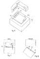
- Fig. 3ais the in Fig. 2 shown light head 4 shown separately, in a perspective view of that side which is provided for connection to the LED module 2.
- Fig. 3ba corresponding view is shown on this interface.
- Fig. 4this in Fig. 2 shown LED module 2 shown separately, in a perspective view of that side, which is provided for connection to the light head 4.
- Fig. 5shows the LED module 2 from another side, so that the bulbs are visible.
- the means for producing the detachable electrical connection between the LED module 2 and the light head 4may have plug contacts; these can - in Fig. 4 shown - contact pins 40 which are arranged on one of the two components LED module 2 or light head 4.
- the contact pins 40are arranged on the LED module 2.
- eleven pins 40are provided. In each case, a contact pin 40 serves to realize an electrical pole of the connection.
- the plug contactscan continue on the corresponding other component, in the example shown so on the light head 4, for each contact pin 40 a counter element, for example in the form of a contact spring 42 include.
- the means for producing the detachable electrical connection between the LED module 2 and the light head 4may alternatively or additionally also have sliding contacts and / or spring contacts and / or cutting contacts.
- the meansare also designed to produce a detachable mechanical connection between the LED module 2 and the light head 4.
- a detachable mechanical connectionbetween the LED module 2 and the light head 4.
- T-shaped elements 50 and on the other component, in this case the light head 4corresponding recesses 52, such that by interaction of the T-shaped Elements 50 and the recesses 52 by means of a Translational movement and a subsequent rotational movement between the two components 2, 4 make the mechanical connection.
- the means for producing the electrical and mechanical connectionare in this case designed to produce or release the connection only by means of a translation movement and a rotational movement.
- the contact pins 40are arranged for this purpose on a first circular path, wherein the center of the first circular path is located on the axis of rotation of the rotational movement.
- the T-shaped elements 50are arranged on a second circular path whose center coincides with the center of the first circular path.
- the radius of the first circular pathis greater than the radius of the second circular path. In principle, however, the radius of the first circular path may be smaller than the radius of the second circular path.
- a particularly simple handling in the operation of the LED lightis possible if the means are designed such that the connection can be made without the aid of a tool and released again.
- the embodiment shown aboveis suitable for this purpose.
- FIGS. 6 and 7Sketches for a first variant of the connection between the LED module 2 and the light head 4 are shown. It shows Fig. 6 a perspective sketch of the relevant parts and Fig. 7 a corresponding cross-section.
- the meansare designed to establish or release the connection by two successive translational movements of different directions. These directions are in Fig. 6 indicated by the arrows "1" and "2". The directions may in particular be perpendicular to each other.
- corresponding contact springs 42 'may be provided.
- the contact pins 40 'are here arranged along a line which is perpendicular to that translational movement, which represents the second translational movement when the connection is made. Therefore, one can speak here of a "linear locking with frontal contacting".
- a slotted guidecan be provided, as in Fig. 7 indicated. Furthermore, this can be done on one of the two mentioned components 2, 4 - as in Fig. 6 indicated - L-shaped holding elements 50 'and on the other component 4, 2 corresponding recesses 52' may be provided, in which the holding elements 50 'can engage.
- the L-legs of the L-shaped holding elements 50 'are in turn aligned along the two directions of translational movements.
- FIG. 8Another variant of the compound is in Fig. 8 outlined.
- a hook-in element 60 and a latching element 62can be provided on one of the two components 2, 4 and corresponding counter-elements on the other component 4, 2.
- the suspension element 60serves in particular to secure the axis of rotation.
- FIGS. 9 and 10 sketchesare shown to a third variant for the connection.
- the contact pins 40formed rectilinear and formed as counter-elements contact springs 42" provided.
- two translational movementsare provided; these are in Fig. 9 indicated by the two arrows "1" and "2".
- a sliding guidecan be provided for mechanical connection.
- the contact pins 40are here arranged along a line which runs parallel to that translational movement which represents the second translational movement when the connection is made. Therefore, it can be said here of a" linear locking with lateral contacting ".
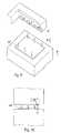
- FIGS. 11 to 13 sketchesare shown to a fourth variant for the connection.
- the counter elementsare in particular in Fig. 13 to recognize that a cross-sectional sketch along in Fig. 11 marked line shows.
- two translational movementsare provided; these are in Fig. 11 indicated by the two arrows "1" and "2".
- Fig. 12 indicatedcan for mechanical connection in turn be provided a slotted guide.
- a slotted guidecan be spoken of a "linear locking with front-side contacting".
- the LED module 2 a in Fig. 4have designated module surface 6 and the light head 4 or preferably directly the heat sink 3 in a Fig. 3b Have designated heat sink surface 7, such that in the connected state, the module surface 6, the heat sink surface 7 contacted surface.
- the T-shaped elements 50may be disposed directly on the module surface 6 and the corresponding recesses 52 on the heat sink surface 7. This is particularly advantageous in terms of heat dissipation from the LED, as a result, a particularly intensive areal contact between the both surfaces mentioned and thus produce a particularly good heat transfer.
- the LED module 2may have in its interior a circuit board on which the at least one LED is arranged or a plurality of LEDs are arranged.
- the boardis advantageously connected to the outer surface 14 with good thermal conductivity.
- a thermal compoundcan be used for this purpose.
- copper pinsmay be provided to transfer heat from the LED to the outer surface 14. Copper pins can also or alternatively be provided to conduct heat from the LED to the module surface 6 in order to improve the heat flow to the heat sink 3 in this way.
- the illustrated LED lamp 1may be formed as an LED spotlight.
- the LED light 1, as in Fig. 1indicated having a support arm 20 which is connected on the one hand to the light head 4 and on the other hand with a (not shown) lamp operating device, which may be arranged for example in the region of a light rail, which is provided for holding the LED lamp 1.
Landscapes
- Engineering & Computer Science (AREA)
- General Engineering & Computer Science (AREA)
- Physics & Mathematics (AREA)
- Microelectronics & Electronic Packaging (AREA)
- Optics & Photonics (AREA)
- Non-Portable Lighting Devices Or Systems Thereof (AREA)
- Arrangement Of Elements, Cooling, Sealing, Or The Like Of Lighting Devices (AREA)
Description
Translated fromGermanDie Erfindung betrifft eine LED-Leuchte (LED: Licht emittierende Diode), die ein LED-Modul mit wenigstens einer LED als Leuchtmittel sowie einen Lichtkopf mit einem Kühlkörper aufweist, wobei das LED-Modul zur Abfuhr von Wärme, die durch die LED erzeugt werden kann, thermisch mit dem Kühlkörper verbunden ist.The invention relates to an LED lamp (LED: light-emitting diode), which has an LED module with at least one LED as the light source and a light head with a heat sink, wherein the LED module for dissipating heat generated by the LED can, is thermally connected to the heat sink.
Derartige LED-Leuchten sind aus dem Stand der Technik bekannt. Bei dem Wunsch, die optischen Eigenschaften der LED-Leuchte zu verändern, wenn also beispielsweise ein andersfarbiges Abstrahllicht gewünscht ist, wird zumeist einfach die gesamte LED-Leuchte ausgetauscht.Such LED lights are known from the prior art. In the desire to change the optical properties of the LED light, so if, for example, a different colored emission light is desired, usually the entire LED light is replaced.
Aus der
Aus der
Aus der
Aus der
Der Erfindung liegt die Aufgabe zu Grunde, eine LED-Leuchte mit verbesserten Möglichkeiten zur Einflussnahme auf das Abstrahlverhalten der Leuchte anzugeben.The invention is based on the object of specifying an LED lamp with improved possibilities for influencing the emission behavior of the luminaire.
Diese Aufgabe wird gemäß der Erfindung mit dem in dem unabhängigen Anspruch genannten Gegenstand gelöst. Besondere Ausführungsarten sind in den abhängigen Ansprüchen angegeben.This object is achieved according to the invention with the object mentioned in the independent claim. Particular embodiments are specified in the dependent claims.
Gemäß der Erfindung ist eine LED-Leuchte vorgesehen, die ein LED-Modul mit wenigstens einer LED als Leuchtmittel und einen Lichtkopf mit einem Kühlkörper aufweist, wobei das LED-Modul zur Abfuhr von Wärme, die durch die LED erzeugt werden kann, thermisch mit dem Kühlkörper verbunden ist. Weiterhin weist die LED-Leuchte Mittel zur Herstellung einer lösbaren elektrischen, wenigstens zweipoligen Verbindung zwischen dem LED-Modul und dem Lichtkopf und zur Herstellung einer lösbaren mechanischen Verbindung zwischen dem LED-Modul und dem Lichtkopf auf. Die Mittel sind dabei dazu ausgebildet, die Verbindung entweder durch zwei aufeinanderfolgende Translationsbewegungen unterschiedlicher Richtungen oder durch eine Translationsbewegung und eine Rotationsbewegung oder lediglich durch eine Rotationsbewegung herzustellen bzw. zu lösen.According to the invention, an LED light is provided, which has an LED module with at least one LED as a light source and a light head with a heat sink, wherein the LED module for dissipating heat that can be generated by the LED, thermally with the Heat sink is connected. Furthermore, the LED lamp has means for producing a detachable electrical, at least two-pole connection between the LED module and the light head and for establishing a releasable mechanical connection between the LED module and the light head. The means are designed to establish or release the connection either by two successive translational movements of different directions or by a translational movement and a rotational movement or merely by a rotational movement.
Durch die Mittel zur Herstellung einer lösbaren elektrischen, wenigstens zweipoligen Verbindung zwischen dem LED-Modul und dem Lichtkopf werden besonders gute Ansteuermöglichkeiten für die LED ermöglicht; vorzugsweise weist die LED-Leuchte Mittel zur Herstellung einer lösbaren elektrischen, wenigstens dreipoligen Verbindung zwischen dem LED-Modul und dem Lichtkopf auf. Hierdurch können beispielsweise unterschiedliche, als Leuchtmittel dienende und unterschiedlich farbiges Licht abstrahlende LEDs angesteuert werden. Auch so genannte back-Kanäle, beispielsweise für Temperatursensorik etc., sind hierdurch ermöglicht.By the means for producing a detachable electrical, at least two-pole connection between the LED module and the light head particularly good control options for the LED allows; Preferably, the LED lamp has means for producing a detachable electrical, at least three-pole connection between the LED module and the light head. As a result, for example, different, serving as a light source and different colored light emitting LEDs can be controlled. Also so-called back channels, for example, for temperature sensors, etc., are thereby made possible.
Vorteilhaft sind die Mittel zur Herstellung einer wenigstens neunpoligen Verbindung zwischen dem LED-Modul und dem Lichtkopf ausgebildet. Dies ermöglicht besonders vielfältige Ansteuermöglichkeiten. Beispielsweise können elf Pole vorgesehen sein.The means for producing an at least nine-pole connection between the LED module and the light head are advantageously formed. This allows particularly diverse control options. For example, eleven poles may be provided.
Vorteilhaft sind die Mittel auch zur Herstellung einer lösbaren mechanischen Verbindung zwischen dem LED-Modul und dem Lichtkopf ausgebildet. Hierdurch wird ermöglicht, dass bei einem Defekt des LED-Moduls lediglich dieses ersetzt wird. Der Lichtkopf, sowie gegebenenfalls weitere Bauteile der LED-Leuchte, beispielsweise ein Betriebsgerät und Stromkabel, können am Aufstellort der LED-Leuchte in montiertem Zustand verbleiben. Auch ein Wechsel des LED-Moduls durch ein anderes LED-Modul, das beispielsweise andere optische Eigenschaften aufweist, ist hierdurch auf einfache Weise möglich. Außerdem kann die LED-Leuchte besonders leicht gewartet werden, weil durch ein Lösen des LED-Moduls von dem Lichtkopf die Zugänglichkeit zu dem LED-Modul, sowie zu denjenigen Bereichen von LED-Modul und Lichtkopf verbessert wird, die zum gegenseitigen Kontakt vorgesehen sind.Advantageously, the means are also designed to produce a releasable mechanical connection between the LED module and the light head. This makes it possible that in case of a defect of the LED module, only this is replaced. The lighthead, and optionally other components of the LED light, such as an operating device and power cable, can remain in the installed state at the installation of the LED light. Also, a change of the LED module by another LED module, for example, has other optical properties, this is possible in a simple manner. In addition, the LED lamp can be particularly easily maintained, because by releasing the LED module from the light head accessibility to the LED module, as well as to those areas of the LED module and light head, which are provided for mutual contact.
Vorteilhaft umfasst das LED-Modul wenigstens zwei, vorzugsweise wenigstens drei LEDs, die jeweils Licht einer anderen Farbe erzeugen können.Advantageously, the LED module comprises at least two, preferably at least three LEDs, each of which can generate light of a different color.
Erfindungsgemäß umfassen die Mittel Steckkontakte und die Steckkontakte Kontaktstifte, wobei jeweils ein Kontaktstift zur Realisierung eines elektrischen Pols der Verbindung dient, wobei die Mittel außerdem weitere Elemente zur mechanischen Verbindung zwischen dem LED-Modul und dem Lichtkopf aufweisen.According to the invention, the means comprise plug contacts and the plug contacts contact pins, wherein in each case a contact pin for the realization of an electrical pole of the connection, wherein the means also comprise further elements for mechanical connection between the LED module and the light head.
Vorteilhaft sind die Mittel derart ausgebildet, dass die Verbindung werkzeuglos hergestellt und gelöst werden kann. Auf diese Weise ist die Handhabung besonders einfach.Advantageously, the means are designed such that the connection can be made and released without tools. In this way, handling is particularly easy.
Eine besonders gute Wärmeübertragung ist ermöglicht, wenn das LED-Modul eine Modul-Fläche aufweist und der Kühlkörper eine Kühlkörper-Fläche, und zwar derart, dass im verbundenen Zustand die Modul-Fläche die Kühlkörper-Fläche flächig kontaktiert.A particularly good heat transfer is possible when the LED module has a module surface and the heat sink a heat sink surface, in such a way that in the connected state, the module surface the heat sink surface area contacted.
Vorteilhaft weist die LED-Leuchte weiterhin ein Lampenbetriebsgerät auf, wobei das Lampenbetriebsgerät vorzugsweise über einen Tragarm mit dem Lichtkopf und/oder mit dem LED-Modul verbunden ist.Advantageously, the LED lamp further comprises a lamp operating device, wherein the lamp operating device is preferably connected via a support arm to the light head and / or to the LED module.
Die LED-Leuchte ist besonders vorteilhaft, wenn sie ein LED-Strahler oder ein LED-Downlight ist.The LED light is particularly advantageous if it is an LED spotlight or an LED downlight.
Die Erfindung wird im Folgenden anhand eines Ausführungsbeispiels und mit Bezug auf die Zeichnungen näher erläutert. Es zeigen:
- Fig. 1
- eine schematische perspektivische Ansicht eines Ausführungsbeispiels einer erfindungsgemäßen LED-Leuchte in Form eines LED-Strahlers,
- Fig. 2
- eine Ansicht des Lichtkopfs und des damit verbundenen LED-Moduls einer erfindungsgemäßen LED-Leuchte,
- Fig. 3a
- eine perspektivische Ansicht des in
Fig. 2 gezeigten Lichtkopfs, - Fig. 3b
- eine weitere Ansicht des Lichtkopfs, und zwar auf diejenige Fläche, die zur Verbindung mit dem LED-Modul vorgesehen ist.
- Fig. 4
- eine Ansicht des in
Fig. 2 gezeigten LED-Moduls, - Fig. 5
- eine weitere Ansicht des in
Fig. 2 gezeigten LED-Moduls aus einer anderen Perspektive, Figuren 6 und 7- Skizzen zu einer ersten Variante der Verbindungsart zwischen dem LED-Modul und dem Lichtkopf,
- Fig. 8
- eine Skizze zu einer zweiten Variante,
- Figuren 9 und 10
- Skizzen zu einer dritten Variante, und
- Figuren 11 bis 13
- Skizzen zu einer vierten Variante der Verbindungsart zwischen dem LED-Modul und dem Lichtkopf.
- Fig. 1
- a schematic perspective view of an embodiment of an LED lamp according to the invention in the form of an LED spotlight,
- Fig. 2
- a view of the light head and the associated LED module of an LED lamp according to the invention,
- Fig. 3a
- a perspective view of the in
Fig. 2 shown lighthead, - Fig. 3b
- another view of the light head, on the surface which is provided for connection to the LED module.
- Fig. 4
- a view of the in
Fig. 2 shown LED module, - Fig. 5
- another view of the in
Fig. 2 shown LED module from a different perspective, - FIGS. 6 and 7
- Sketches for a first variant of the type of connection between the LED module and the light head,
- Fig. 8
- a sketch to a second variant,
- FIGS. 9 and 10
- Sketches to a third variant, and
- FIGS. 11 to 13
- Sketches for a fourth variant of the connection between the LED module and the light head.
In
Das LED-Modul 2 kann insbesondere wenigstens zwei, vorzugsweise wenigstens drei LEDs umfassen, die jeweils Licht einer anderen Farbe erzeugen können. In diesem Fall lässt sich mit der LED-Leuchte Licht in besonders vielen unterschiedlichen Farben erzeugen.The
Die LED-Leuchte 1 weist weiterhin Mittel zur Herstellung einer lösbaren elektrischen, wenigstens zweipoligen, vorzugsweise wenigstens dreipoligen Verbindung zwischen dem LED-Modul 2 und dem Lichtkopf 4 auf. Auf diese Weise wird eine besonders vielfältige Ansteuerung der LED bzw. der LEDs ermöglicht. Beispielsweise kann eine wenigstens neunpolige elektrische Verbindung zwischen dem LED-Modul und dem Lichtkopf vorgesehen sein. Beim Ausführungsbeispiel kann also beispielsweise eine elfpolige Verbindung vorgesehen sein.The
In
In
Die Mittel zur Herstellung der lösbaren elektrischen Verbindung zwischen dem LED-Modul 2 und dem Lichtkopf 4 können Steckkontakte aufweisen; diese können - in
Die Steckkontakte können weiterhin am entsprechend anderen Bauteil, im gezeigten Beispiel also am Lichtkopf 4, für jeden Kontaktstift 40 ein Gegenelement, beispielsweise in Form einer Kontaktfeder 42 umfassen.The plug contacts can continue on the corresponding other component, in the example shown so on the
Die Mittel zur Herstellung der lösbaren elektrischen Verbindung zwischen dem LED-Modul 2 und dem Lichtkopf 4 können alternativ oder zusätzlich auch Schleifkontakte und/oder Federkontakte und/oder Schneidkontakte aufweisen.The means for producing the detachable electrical connection between the
Vorteilhaft sind die Mittel auch zur Herstellung einer lösbaren mechanischen Verbindung zwischen dem LED-Modul 2 und dem Lichtkopf 4 ausgebildet. Wie aus den
Die Mittel zur Herstellung der elektrischen und mechanischen Verbindung sind in diesem Fall dazu ausgebildet, die Verbindung lediglich durch eine Translationbewegung und eine Rotationsbewegung herzustellen bzw. zu lösen. Die Kontaktstifte 40 sind hierzu auf einer ersten Kreisbahn angeordnet, wobei der Mittelpunkt der ersten Kreisbahn auf der Rotationsachse der Rotationsbewegung liegt. Die T-förmigen Elemente 50 sind auf einer zweiten Kreisbahn angeordnet, deren Mittelpunkt mit dem Mittelpunkt der ersten Kreisbahn zusammenfällt. Im gezeigten Beispiel ist der Radius der ersten Kreisbahn größer als der Radius der zweiten Kreisbahn. Grundsätzlich kann jedoch auch der Radius der ersten Kreisbahn kleiner sein als der Radius der zweiten Kreisbahn.The means for producing the electrical and mechanical connection are in this case designed to produce or release the connection only by means of a translation movement and a rotational movement. The contact pins 40 are arranged for this purpose on a first circular path, wherein the center of the first circular path is located on the axis of rotation of the rotational movement. The T-shaped
Eine besonders einfache Handhabung bei der Bedienung der LED-Leuchte ist möglich, wenn die Mittel derart ausgebildet sind, dass die Verbindung ohne Zuhilfenahme eines Werkzeugs hergestellt und wieder gelöst werden kann. Die oben dargestellte Ausführungsform eignet sich hierzu.A particularly simple handling in the operation of the LED light is possible if the means are designed such that the connection can be made without the aid of a tool and released again. The embodiment shown above is suitable for this purpose.
In den
Zur gleichzeitigen mechanischen Verbindung kann beispielsweise eine Kulissenführung vorgesehen sein, wie in
Eine weitere Variante zur Verbindung ist in
In den
In den
Zur besonders guten Wärmeleitung kann das LED-Modul 2 eine in
Insbesondere können die T-förmigen Elemente 50 unmittelbar an der Modul-Fläche 6 angeordnet sein und die entsprechenden Vertiefungen 52 an der Kühlkörper-Fläche 7. Dies ist hinsichtlich der Wärmeableitung von der LED besonders vorteilhaft, weil sich hierdurch ein besonders intensiver flächiger Kontakt zwischen den beiden genannten Flächen und damit eine besonders gute Wärmeübertragung herstellen lässt.In particular, the T-shaped
Das LED-Modul 2 kann in seinem Inneren eine Platine aufweisen, auf der die wenigstens eine LED angeordnet ist bzw. mehrere LEDs angeordnet sind. Vorteilhaft ist in diesem Fall die Platine gut wärmeleitend mit der Außenfläche 14 verbunden. Beispielsweise kann hierfür eine Wärmeleitpaste verwendet werden. Auch können Kupferstifte vorgesehen sein, um Wärme von der LED zur Außenfläche 14 zu übertragen. Kupferstifte können auch oder alternativ dafür vorgesehen sein, Wärme von der LED zur Modulfläche 6 zu leiten, um auf diese Weise den Wärmefluss zum Kühlkörper 3 hin zu verbessern.The
Die dargestellte LED-Leuchte 1 kann als LED-Strahler ausgebildet sein. Hierzu kann die LED-Leuchte 1, wie in
Claims (8)
- An LED luminaire having- an LED module (2) with at least one LED as a luminous means, and- a light head (4) with a heat sink (3),wherein in order to dissipate heat, which can be generated by the LED, the LED module (2) is thermally connected to the heat sink (3),- means (40, 40', 40", 40"', 42, 42', 42'", 42"', 50, 50', 52, 52', 60, 62) for establishing a releasable electrical, at least two-pole connection between the LED module (2) and the light head (4) and for establishing a releasable mechanical connection between the LED module (2) and the light head (4),wherein the means (40, 40', 40", 40"', 42, 42', 42", 42"', 50, 50', 52, 52', 60, 62) are configured to establish or release both the electrical connection and the mechanical connection either by means of two successive translational movements in different directions or by means of one translational movement and one rotational movement or merely by means of one rotational movement,
characterised in that
the means (40, 40', 40", 40"', 42, 42', 42", 42"', 50, 50', 52, 52', 60, 62) comprise:a) plug contacts which comprise contact pins (40, 40', 40", 40"'),
wherein in each case one contact pin (40, 40', 40", 40"') is used to realize one electrical pole of the connection, and alsob) further elements (50, 50', 52, 52', 60, 62) which are configured to establish the releasable mechanical connection between the LED module (2) and the light head (4). - An LED luminaire according to claim 1,
in which the means (40, 40', 40" , 40"', 42, 42', 42", 42"', 50, 50', 52, 52', 60, 62) are configured to establish an at least nine-pole connection between the LED module (2) and the light head (4). - An LED luminaire according to one of the preceding claims,
in which the LED module (2) comprises at least two, preferably at least three LEDs which can each generate light of a different colour. - An LED luminaire according to one of the preceding claims,
in which the means (40, 40', 40", 40"', 42, 42', 42", 42"', 50, 50', 52, 52', 60, 62) are configured in such a way that the connection can be established and released without tools. - An LED luminaire according to one of the preceding claims,
in which the LED module (2) has a module face (6) and the heat sink (3) has a heat-sink face (7) in such a way that in the connected state the module face (6) contacts the heat-sink face (7) over an area. - An LED luminaire according to one of the preceding claims,
having, furthermore, a lamp-operating device, wherein the lamp-operating device is connected to the light head and/or to the LED module (2) preferably by way of a supporting arm (20). - An LED luminaire according to one of the preceding claims,
wherein the LED luminaire is an LED spotlight. - An LED luminaire according to one of the preceding claims 1 to 6,
wherein the LED luminaire is an LED downlight.
Applications Claiming Priority (2)
| Application Number | Priority Date | Filing Date | Title |
|---|---|---|---|
| DE102009014485ADE102009014485A1 (en) | 2009-03-23 | 2009-03-23 | LED light |
| PCT/EP2010/053749WO2010108906A1 (en) | 2009-03-23 | 2010-03-23 | Led luminaire |
Publications (2)
| Publication Number | Publication Date |
|---|---|
| EP2411732A1 EP2411732A1 (en) | 2012-02-01 |
| EP2411732B1true EP2411732B1 (en) | 2015-01-14 |
Family
ID=42144871
Family Applications (1)
| Application Number | Title | Priority Date | Filing Date |
|---|---|---|---|
| EP10712039.6ANot-in-forceEP2411732B1 (en) | 2009-03-23 | 2010-03-23 | Led luminaire |
Country Status (3)
| Country | Link |
|---|---|
| EP (1) | EP2411732B1 (en) |
| DE (1) | DE102009014485A1 (en) |
| WO (1) | WO2010108906A1 (en) |
Families Citing this family (6)
| Publication number | Priority date | Publication date | Assignee | Title |
|---|---|---|---|---|
| DE102010039120A1 (en)* | 2010-08-10 | 2012-02-16 | Osram Ag | Circuit board of lamp system, has attachment element that is provided in back side and is configured as electrical transmission element for semiconductor light source |
| WO2012052870A1 (en)* | 2010-10-19 | 2012-04-26 | Koninklijke Philips Electronics N.V. | Compact replaceable led module |
| EP2466198B1 (en)* | 2010-12-17 | 2015-08-26 | Vossloh-Schwabe Italia SPA | Heat sinking light source holder |
| JP5834219B2 (en)* | 2011-03-04 | 2015-12-16 | パナソニックIpマネジメント株式会社 | Lighting device |
| EP2503221A3 (en)* | 2011-03-23 | 2013-03-06 | Toshiba Lighting & Technology Corporation | Light-emitting module, light-emitting module unit, and luminaire |
| ITMI20120886A1 (en) | 2012-05-22 | 2013-11-23 | Marco Gaeta | LED LAMP HOLDER |
Citations (1)
| Publication number | Priority date | Publication date | Assignee | Title |
|---|---|---|---|---|
| WO2010051985A2 (en)* | 2008-11-05 | 2010-05-14 | Zumtobel Lighting Gmbh & Co.Kg. | Led luminaire |
Family Cites Families (12)
| Publication number | Priority date | Publication date | Assignee | Title |
|---|---|---|---|---|
| US5947588A (en)* | 1997-10-06 | 1999-09-07 | Grand General Accessories Manufacturing Inc. | Light fixture with an LED light bulb having a conventional connection post |
| US6715900B2 (en)* | 2002-05-17 | 2004-04-06 | A L Lightech, Inc. | Light source arrangement |
| DE102004062990A1 (en)* | 2004-12-22 | 2006-07-06 | Patent-Treuhand-Gesellschaft für elektrische Glühlampen mbH | Lighting device with at least one light emitting diode and vehicle headlights |
| US7588359B2 (en)* | 2005-09-26 | 2009-09-15 | Osram Sylvania Inc. | LED lamp with direct optical coupling in axial arrangement |
| TWI280332B (en)* | 2005-10-31 | 2007-05-01 | Guei-Fang Chen | LED lighting device |
| CN100454595C (en)* | 2005-12-09 | 2009-01-21 | 富准精密工业(深圳)有限公司 | LED Module |
| DE202006002583U1 (en)* | 2006-02-16 | 2007-06-28 | Halemeier Gmbh & Co. Kg | LED light |
| US7527397B2 (en)* | 2006-09-26 | 2009-05-05 | Chia-Mao Li | Solid state lighting package structure |
| TWI342625B (en)* | 2007-02-14 | 2011-05-21 | Neobulb Technologies Inc | Light-emitting diode illuminating equipment |
| US7972038B2 (en)* | 2007-08-01 | 2011-07-05 | Osram Sylvania Inc. | Direct view LED lamp with snap fit housing |
| US7866850B2 (en)* | 2008-02-26 | 2011-01-11 | Journée Lighting, Inc. | Light fixture assembly and LED assembly |
| DE202008015129U1 (en)* | 2008-11-14 | 2009-01-29 | CERAMATE TECHNICAL CO., LTD., Luch | Combined recessed lamp without lampshade |
- 2009
- 2009-03-23DEDE102009014485Apatent/DE102009014485A1/ennot_activeWithdrawn
- 2010
- 2010-03-23WOPCT/EP2010/053749patent/WO2010108906A1/enactiveApplication Filing
- 2010-03-23EPEP10712039.6Apatent/EP2411732B1/ennot_activeNot-in-force
Patent Citations (1)
| Publication number | Priority date | Publication date | Assignee | Title |
|---|---|---|---|---|
| WO2010051985A2 (en)* | 2008-11-05 | 2010-05-14 | Zumtobel Lighting Gmbh & Co.Kg. | Led luminaire |
Also Published As
| Publication number | Publication date |
|---|---|
| DE102009014485A1 (en) | 2010-09-30 |
| WO2010108906A1 (en) | 2010-09-30 |
| EP2411732A1 (en) | 2012-02-01 |
Similar Documents
| Publication | Publication Date | Title |
|---|---|---|
| EP2350528B1 (en) | Led luminaire | |
| EP1721102B1 (en) | Lamp | |
| EP2411732B1 (en) | Led luminaire | |
| DE102009008096B4 (en) | Heat sink for a lighting device | |
| EP2976566B1 (en) | Lighting device with an led lighting module | |
| DE102018117378A1 (en) | Power supply, lamp, mobile device and method of making a power supply | |
| DE202010006197U1 (en) | Led lamp | |
| DE102009022255A1 (en) | LED with heat sink | |
| DE102010052020B4 (en) | Lighting and / or display device | |
| DE102007055133A1 (en) | Lighting device with a heat sink | |
| WO2012140146A1 (en) | Lighting device | |
| EP2171352B1 (en) | Lamp | |
| DE202014008377U1 (en) | Lamp device with the possibility of changing a spatial light emission angle | |
| DE202016107013U1 (en) | Lighting unit, in particular for a screen lamp, and lamp, in particular screen lamp, with a lighting unit | |
| EP3217084B1 (en) | Lamp | |
| DE102012215934B4 (en) | lighting system | |
| WO2015040240A1 (en) | Lamp | |
| WO2014094006A1 (en) | Light‑emitting means, in particular led module | |
| DE202010008309U1 (en) | Led lamp | |
| EP3171078B1 (en) | Led light source | |
| EP2629004B1 (en) | Recessed luminaire for outdoor use, in particular for mounting in a window frame profile | |
| EP3620836A1 (en) | Dmd module | |
| DE102007059061B4 (en) | Luminaire with at least one light source | |
| EP2910843A1 (en) | Lighting device | |
| DE202017104975U1 (en) | LED lighting device |
Legal Events
| Date | Code | Title | Description |
|---|---|---|---|
| PUAI | Public reference made under article 153(3) epc to a published international application that has entered the european phase | Free format text:ORIGINAL CODE: 0009012 | |
| 17P | Request for examination filed | Effective date:20110922 | |
| AK | Designated contracting states | Kind code of ref document:A1 Designated state(s):AT BE BG CH CY CZ DE DK EE ES FI FR GB GR HR HU IE IS IT LI LT LU LV MC MK MT NL NO PL PT RO SE SI SK SM TR | |
| DAX | Request for extension of the european patent (deleted) | ||
| 17Q | First examination report despatched | Effective date:20130507 | |
| REG | Reference to a national code | Ref country code:DE Ref legal event code:R079 Ref document number:502010008730 Country of ref document:DE Free format text:PREVIOUS MAIN CLASS: F21V0029000000 Ipc:F21V0019000000 | |
| GRAP | Despatch of communication of intention to grant a patent | Free format text:ORIGINAL CODE: EPIDOSNIGR1 | |
| RIC1 | Information provided on ipc code assigned before grant | Ipc:F21V 21/30 20060101ALN20140828BHEP Ipc:F21V 23/00 20060101ALI20140828BHEP Ipc:H01R 33/46 20060101ALN20140828BHEP Ipc:F21V 23/02 20060101ALN20140828BHEP Ipc:F21V 19/04 20060101ALI20140828BHEP Ipc:F21V 17/10 20060101ALN20140828BHEP Ipc:F21V 19/00 20060101AFI20140828BHEP Ipc:F21Y 101/02 20060101ALI20140828BHEP Ipc:F21V 29/00 20060101ALI20140828BHEP | |
| INTG | Intention to grant announced | Effective date:20141001 | |
| GRAS | Grant fee paid | Free format text:ORIGINAL CODE: EPIDOSNIGR3 | |
| GRAA | (expected) grant | Free format text:ORIGINAL CODE: 0009210 | |
| RAP1 | Party data changed (applicant data changed or rights of an application transferred) | Owner name:TRIDONIC JENNERSDORF GMBH Owner name:TRIDONIC GMBH & CO. KG | |
| AK | Designated contracting states | Kind code of ref document:B1 Designated state(s):AT BE BG CH CY CZ DE DK EE ES FI FR GB GR HR HU IE IS IT LI LT LU LV MC MK MT NL NO PL PT RO SE SI SK SM TR | |
| REG | Reference to a national code | Ref country code:GB Ref legal event code:FG4D Free format text:NOT ENGLISH | |
| REG | Reference to a national code | Ref country code:CH Ref legal event code:EP | |
| REG | Reference to a national code | Ref country code:IE Ref legal event code:FG4D Free format text:LANGUAGE OF EP DOCUMENT: GERMAN | |
| REG | Reference to a national code | Ref country code:AT Ref legal event code:REF Ref document number:707262 Country of ref document:AT Kind code of ref document:T Effective date:20150215 | |
| REG | Reference to a national code | Ref country code:DE Ref legal event code:R096 Ref document number:502010008730 Country of ref document:DE Effective date:20150305 | |
| REG | Reference to a national code | Ref country code:NL Ref legal event code:VDEP Effective date:20150114 | |
| REG | Reference to a national code | Ref country code:LT Ref legal event code:MG4D | |
| PG25 | Lapsed in a contracting state [announced via postgrant information from national office to epo] | Ref country code:SE Free format text:LAPSE BECAUSE OF FAILURE TO SUBMIT A TRANSLATION OF THE DESCRIPTION OR TO PAY THE FEE WITHIN THE PRESCRIBED TIME-LIMIT Effective date:20150114 Ref country code:NO Free format text:LAPSE BECAUSE OF FAILURE TO SUBMIT A TRANSLATION OF THE DESCRIPTION OR TO PAY THE FEE WITHIN THE PRESCRIBED TIME-LIMIT Effective date:20150414 Ref country code:BG Free format text:LAPSE BECAUSE OF FAILURE TO SUBMIT A TRANSLATION OF THE DESCRIPTION OR TO PAY THE FEE WITHIN THE PRESCRIBED TIME-LIMIT Effective date:20150414 Ref country code:FI Free format text:LAPSE BECAUSE OF FAILURE TO SUBMIT A TRANSLATION OF THE DESCRIPTION OR TO PAY THE FEE WITHIN THE PRESCRIBED TIME-LIMIT Effective date:20150114 Ref country code:HR Free format text:LAPSE BECAUSE OF FAILURE TO SUBMIT A TRANSLATION OF THE DESCRIPTION OR TO PAY THE FEE WITHIN THE PRESCRIBED TIME-LIMIT Effective date:20150114 Ref country code:LT Free format text:LAPSE BECAUSE OF FAILURE TO SUBMIT A TRANSLATION OF THE DESCRIPTION OR TO PAY THE FEE WITHIN THE PRESCRIBED TIME-LIMIT Effective date:20150114 Ref country code:ES Free format text:LAPSE BECAUSE OF FAILURE TO SUBMIT A TRANSLATION OF THE DESCRIPTION OR TO PAY THE FEE WITHIN THE PRESCRIBED TIME-LIMIT Effective date:20150114 | |
| REG | Reference to a national code | Ref country code:CH Ref legal event code:NV Representative=s name:FIAMMENGHI-FIAMMENGHI, CH | |
| PG25 | Lapsed in a contracting state [announced via postgrant information from national office to epo] | Ref country code:PL Free format text:LAPSE BECAUSE OF FAILURE TO SUBMIT A TRANSLATION OF THE DESCRIPTION OR TO PAY THE FEE WITHIN THE PRESCRIBED TIME-LIMIT Effective date:20150114 Ref country code:LV Free format text:LAPSE BECAUSE OF FAILURE TO SUBMIT A TRANSLATION OF THE DESCRIPTION OR TO PAY THE FEE WITHIN THE PRESCRIBED TIME-LIMIT Effective date:20150114 Ref country code:GR Free format text:LAPSE BECAUSE OF FAILURE TO SUBMIT A TRANSLATION OF THE DESCRIPTION OR TO PAY THE FEE WITHIN THE PRESCRIBED TIME-LIMIT Effective date:20150415 Ref country code:IS Free format text:LAPSE BECAUSE OF FAILURE TO SUBMIT A TRANSLATION OF THE DESCRIPTION OR TO PAY THE FEE WITHIN THE PRESCRIBED TIME-LIMIT Effective date:20150514 Ref country code:NL Free format text:LAPSE BECAUSE OF FAILURE TO SUBMIT A TRANSLATION OF THE DESCRIPTION OR TO PAY THE FEE WITHIN THE PRESCRIBED TIME-LIMIT Effective date:20150114 | |
| REG | Reference to a national code | Ref country code:DE Ref legal event code:R097 Ref document number:502010008730 Country of ref document:DE | |
| PG25 | Lapsed in a contracting state [announced via postgrant information from national office to epo] | Ref country code:EE Free format text:LAPSE BECAUSE OF FAILURE TO SUBMIT A TRANSLATION OF THE DESCRIPTION OR TO PAY THE FEE WITHIN THE PRESCRIBED TIME-LIMIT Effective date:20150114 Ref country code:RO Free format text:LAPSE BECAUSE OF FAILURE TO SUBMIT A TRANSLATION OF THE DESCRIPTION OR TO PAY THE FEE WITHIN THE PRESCRIBED TIME-LIMIT Effective date:20150114 Ref country code:CZ Free format text:LAPSE BECAUSE OF FAILURE TO SUBMIT A TRANSLATION OF THE DESCRIPTION OR TO PAY THE FEE WITHIN THE PRESCRIBED TIME-LIMIT Effective date:20150114 Ref country code:DK Free format text:LAPSE BECAUSE OF FAILURE TO SUBMIT A TRANSLATION OF THE DESCRIPTION OR TO PAY THE FEE WITHIN THE PRESCRIBED TIME-LIMIT Effective date:20150114 Ref country code:MC Free format text:LAPSE BECAUSE OF FAILURE TO SUBMIT A TRANSLATION OF THE DESCRIPTION OR TO PAY THE FEE WITHIN THE PRESCRIBED TIME-LIMIT Effective date:20150114 Ref country code:LU Free format text:LAPSE BECAUSE OF FAILURE TO SUBMIT A TRANSLATION OF THE DESCRIPTION OR TO PAY THE FEE WITHIN THE PRESCRIBED TIME-LIMIT Effective date:20150323 Ref country code:SK Free format text:LAPSE BECAUSE OF FAILURE TO SUBMIT A TRANSLATION OF THE DESCRIPTION OR TO PAY THE FEE WITHIN THE PRESCRIBED TIME-LIMIT Effective date:20150114 | |
| PLBE | No opposition filed within time limit | Free format text:ORIGINAL CODE: 0009261 | |
| STAA | Information on the status of an ep patent application or granted ep patent | Free format text:STATUS: NO OPPOSITION FILED WITHIN TIME LIMIT | |
| 26N | No opposition filed | Effective date:20151015 | |
| PG25 | Lapsed in a contracting state [announced via postgrant information from national office to epo] | Ref country code:IT Free format text:LAPSE BECAUSE OF FAILURE TO SUBMIT A TRANSLATION OF THE DESCRIPTION OR TO PAY THE FEE WITHIN THE PRESCRIBED TIME-LIMIT Effective date:20150114 | |
| REG | Reference to a national code | Ref country code:IE Ref legal event code:MM4A | |
| PG25 | Lapsed in a contracting state [announced via postgrant information from national office to epo] | Ref country code:IE Free format text:LAPSE BECAUSE OF NON-PAYMENT OF DUE FEES Effective date:20150323 | |
| PG25 | Lapsed in a contracting state [announced via postgrant information from national office to epo] | Ref country code:SI Free format text:LAPSE BECAUSE OF FAILURE TO SUBMIT A TRANSLATION OF THE DESCRIPTION OR TO PAY THE FEE WITHIN THE PRESCRIBED TIME-LIMIT Effective date:20150114 | |
| REG | Reference to a national code | Ref country code:FR Ref legal event code:PLFP Year of fee payment:7 | |
| PG25 | Lapsed in a contracting state [announced via postgrant information from national office to epo] | Ref country code:MT Free format text:LAPSE BECAUSE OF FAILURE TO SUBMIT A TRANSLATION OF THE DESCRIPTION OR TO PAY THE FEE WITHIN THE PRESCRIBED TIME-LIMIT Effective date:20150114 | |
| REG | Reference to a national code | Ref country code:FR Ref legal event code:PLFP Year of fee payment:8 | |
| PG25 | Lapsed in a contracting state [announced via postgrant information from national office to epo] | Ref country code:SM Free format text:LAPSE BECAUSE OF FAILURE TO SUBMIT A TRANSLATION OF THE DESCRIPTION OR TO PAY THE FEE WITHIN THE PRESCRIBED TIME-LIMIT Effective date:20150114 Ref country code:HU Free format text:LAPSE BECAUSE OF FAILURE TO SUBMIT A TRANSLATION OF THE DESCRIPTION OR TO PAY THE FEE WITHIN THE PRESCRIBED TIME-LIMIT; INVALID AB INITIO Effective date:20100323 | |
| PG25 | Lapsed in a contracting state [announced via postgrant information from national office to epo] | Ref country code:CY Free format text:LAPSE BECAUSE OF FAILURE TO SUBMIT A TRANSLATION OF THE DESCRIPTION OR TO PAY THE FEE WITHIN THE PRESCRIBED TIME-LIMIT Effective date:20150114 | |
| PG25 | Lapsed in a contracting state [announced via postgrant information from national office to epo] | Ref country code:BE Free format text:LAPSE BECAUSE OF NON-PAYMENT OF DUE FEES Effective date:20150331 Ref country code:PT Free format text:LAPSE BECAUSE OF FAILURE TO SUBMIT A TRANSLATION OF THE DESCRIPTION OR TO PAY THE FEE WITHIN THE PRESCRIBED TIME-LIMIT Effective date:20150514 | |
| PG25 | Lapsed in a contracting state [announced via postgrant information from national office to epo] | Ref country code:TR Free format text:LAPSE BECAUSE OF FAILURE TO SUBMIT A TRANSLATION OF THE DESCRIPTION OR TO PAY THE FEE WITHIN THE PRESCRIBED TIME-LIMIT Effective date:20150114 | |
| REG | Reference to a national code | Ref country code:FR Ref legal event code:PLFP Year of fee payment:9 | |
| PGFP | Annual fee paid to national office [announced via postgrant information from national office to epo] | Ref country code:CH Payment date:20180323 Year of fee payment:9 | |
| PGFP | Annual fee paid to national office [announced via postgrant information from national office to epo] | Ref country code:AT Payment date:20180328 Year of fee payment:9 | |
| PG25 | Lapsed in a contracting state [announced via postgrant information from national office to epo] | Ref country code:MK Free format text:LAPSE BECAUSE OF FAILURE TO SUBMIT A TRANSLATION OF THE DESCRIPTION OR TO PAY THE FEE WITHIN THE PRESCRIBED TIME-LIMIT Effective date:20150114 | |
| REG | Reference to a national code | Ref country code:DE Ref legal event code:R084 Ref document number:502010008730 Country of ref document:DE | |
| REG | Reference to a national code | Ref country code:CH Ref legal event code:PK Free format text:BERICHTIGUNGEN | |
| RIC2 | Information provided on ipc code assigned after grant | Ipc:F21V 19/00 20060101AFI20140828BHEP Ipc:F21Y 101/02 20000101ALI20140828BHEP Ipc:F21V 17/10 20060101ALN20140828BHEP Ipc:F21V 23/02 20060101ALN20140828BHEP Ipc:F21V 23/00 20150101ALI20140828BHEP Ipc:F21V 29/00 20150101ALI20140828BHEP Ipc:F21V 19/04 20060101ALI20140828BHEP Ipc:F21V 21/30 20060101ALN20140828BHEP Ipc:H01R 33/46 20060101ALN20140828BHEP | |
| REG | Reference to a national code | Ref country code:CH Ref legal event code:PL | |
| REG | Reference to a national code | Ref country code:AT Ref legal event code:MM01 Ref document number:707262 Country of ref document:AT Kind code of ref document:T Effective date:20190323 | |
| PG25 | Lapsed in a contracting state [announced via postgrant information from national office to epo] | Ref country code:LI Free format text:LAPSE BECAUSE OF NON-PAYMENT OF DUE FEES Effective date:20190331 Ref country code:AT Free format text:LAPSE BECAUSE OF NON-PAYMENT OF DUE FEES Effective date:20190323 Ref country code:CH Free format text:LAPSE BECAUSE OF NON-PAYMENT OF DUE FEES Effective date:20190331 | |
| PGFP | Annual fee paid to national office [announced via postgrant information from national office to epo] | Ref country code:FR Payment date:20210326 Year of fee payment:12 | |
| REG | Reference to a national code | Ref country code:DE Ref legal event code:R081 Ref document number:502010008730 Country of ref document:DE Owner name:TRIDONIC GMBH & CO KG, AT Free format text:FORMER OWNERS: TRIDONIC GMBH & CO KG, DORNBIRN, AT; TRIDONIC JENNERSDORF GMBH, JENNERSDORF, AT | |
| PGFP | Annual fee paid to national office [announced via postgrant information from national office to epo] | Ref country code:GB Payment date:20220322 Year of fee payment:13 Ref country code:DE Payment date:20220329 Year of fee payment:13 | |
| PG25 | Lapsed in a contracting state [announced via postgrant information from national office to epo] | Ref country code:FR Free format text:LAPSE BECAUSE OF NON-PAYMENT OF DUE FEES Effective date:20220331 | |
| REG | Reference to a national code | Ref country code:DE Ref legal event code:R119 Ref document number:502010008730 Country of ref document:DE | |
| GBPC | Gb: european patent ceased through non-payment of renewal fee | Effective date:20230323 | |
| PG25 | Lapsed in a contracting state [announced via postgrant information from national office to epo] | Ref country code:GB Free format text:LAPSE BECAUSE OF NON-PAYMENT OF DUE FEES Effective date:20230323 | |
| PG25 | Lapsed in a contracting state [announced via postgrant information from national office to epo] | Ref country code:GB Free format text:LAPSE BECAUSE OF NON-PAYMENT OF DUE FEES Effective date:20230323 Ref country code:DE Free format text:LAPSE BECAUSE OF NON-PAYMENT OF DUE FEES Effective date:20231003 |