EP2410935B1 - Cannula with integrated camera and illumination - Google Patents
Cannula with integrated camera and illuminationDownload PDFInfo
- Publication number
- EP2410935B1 EP2410935B1EP10756938.6AEP10756938AEP2410935B1EP 2410935 B1EP2410935 B1EP 2410935B1EP 10756938 AEP10756938 AEP 10756938AEP 2410935 B1EP2410935 B1EP 2410935B1
- Authority
- EP
- European Patent Office
- Prior art keywords
- deployable portion
- tubular element
- cannula assembly
- closed position
- deployable
- Prior art date
- Legal status (The legal status is an assumption and is not a legal conclusion. Google has not performed a legal analysis and makes no representation as to the accuracy of the status listed.)
- Active
Links
- 238000005286illuminationMethods0.000titleclaimsdescription39
- 230000005540biological transmissionEffects0.000claimsdescription25
- 238000003384imaging methodMethods0.000claimsdescription22
- 230000007246mechanismEffects0.000claimsdescription13
- 230000007704transitionEffects0.000claimsdescription9
- 239000000835fiberSubstances0.000claimsdescription7
- 239000012780transparent materialSubstances0.000claimsdescription7
- 230000000295complement effectEffects0.000claimsdescription5
- 229910044991metal oxideInorganic materials0.000claimsdescription3
- 150000004706metal oxidesChemical class0.000claimsdescription3
- 239000004065semiconductorSubstances0.000claimsdescription3
- 238000000034methodMethods0.000description18
- 238000003780insertionMethods0.000description11
- 230000037431insertionEffects0.000description11
- 239000000463materialSubstances0.000description6
- 229910001285shape-memory alloyInorganic materials0.000description5
- 238000004891communicationMethods0.000description4
- 238000010438heat treatmentMethods0.000description4
- 239000000523sampleSubstances0.000description4
- 241001631457CannulaSpecies0.000description3
- 238000004146energy storageMethods0.000description3
- 230000033001locomotionEffects0.000description3
- 230000003287optical effectEffects0.000description3
- 238000001356surgical procedureMethods0.000description3
- 238000002604ultrasonographyMethods0.000description3
- 230000003044adaptive effectEffects0.000description2
- 238000000605extractionMethods0.000description2
- 238000002324minimally invasive surgeryMethods0.000description2
- 238000012986modificationMethods0.000description2
- 230000004048modificationEffects0.000description2
- 238000001228spectrumMethods0.000description2
- 238000011144upstream manufacturingMethods0.000description2
- 206010052428WoundDiseases0.000description1
- 208000027418Wounds and injuryDiseases0.000description1
- 239000003990capacitorSubstances0.000description1
- 230000008859changeEffects0.000description1
- 230000002596correlated effectEffects0.000description1
- 239000002537cosmeticSubstances0.000description1
- 230000003247decreasing effectEffects0.000description1
- 238000013461designMethods0.000description1
- 238000011161developmentMethods0.000description1
- 238000012976endoscopic surgical procedureMethods0.000description1
- 230000005294ferromagnetic effectEffects0.000description1
- 230000006870functionEffects0.000description1
- 238000007373indentationMethods0.000description1
- 208000015181infectious diseaseDiseases0.000description1
- 208000014674injuryDiseases0.000description1
- 230000005291magnetic effectEffects0.000description1
- 239000002184metalSubstances0.000description1
- 229910001000nickel titaniumInorganic materials0.000description1
- HLXZNVUGXRDIFK-UHFFFAOYSA-Nnickel titaniumChemical compound[Ti].[Ti].[Ti].[Ti].[Ti].[Ti].[Ti].[Ti].[Ti].[Ti].[Ti].[Ni].[Ni].[Ni].[Ni].[Ni].[Ni].[Ni].[Ni].[Ni].[Ni].[Ni].[Ni].[Ni].[Ni]HLXZNVUGXRDIFK-UHFFFAOYSA-N0.000description1
- 210000000056organAnatomy0.000description1
- 238000011084recoveryMethods0.000description1
- 230000009467reductionEffects0.000description1
- 230000004044responseEffects0.000description1
- 239000007787solidSubstances0.000description1
- 230000006641stabilisationEffects0.000description1
- 238000011105stabilizationMethods0.000description1
- 230000008733traumaEffects0.000description1
Images


Classifications
- A—HUMAN NECESSITIES
- A61—MEDICAL OR VETERINARY SCIENCE; HYGIENE
- A61B—DIAGNOSIS; SURGERY; IDENTIFICATION
- A61B17/00—Surgical instruments, devices or methods
- A61B17/34—Trocars; Puncturing needles
- A61B17/3494—Trocars; Puncturing needles with safety means for protection against accidental cutting or pricking, e.g. limiting insertion depth, pressure sensors
- A61B17/3496—Protecting sleeves or inner probes; Retractable tips
- A—HUMAN NECESSITIES
- A61—MEDICAL OR VETERINARY SCIENCE; HYGIENE
- A61B—DIAGNOSIS; SURGERY; IDENTIFICATION
- A61B1/00—Instruments for performing medical examinations of the interior of cavities or tubes of the body by visual or photographical inspection, e.g. endoscopes; Illuminating arrangements therefor
- A61B1/00064—Constructional details of the endoscope body
- A61B1/00071—Insertion part of the endoscope body
- A61B1/0008—Insertion part of the endoscope body characterised by distal tip features
- A61B1/00087—Tools
- A—HUMAN NECESSITIES
- A61—MEDICAL OR VETERINARY SCIENCE; HYGIENE
- A61B—DIAGNOSIS; SURGERY; IDENTIFICATION
- A61B1/00—Instruments for performing medical examinations of the interior of cavities or tubes of the body by visual or photographical inspection, e.g. endoscopes; Illuminating arrangements therefor
- A61B1/04—Instruments for performing medical examinations of the interior of cavities or tubes of the body by visual or photographical inspection, e.g. endoscopes; Illuminating arrangements therefor combined with photographic or television appliances
- A61B1/05—Instruments for performing medical examinations of the interior of cavities or tubes of the body by visual or photographical inspection, e.g. endoscopes; Illuminating arrangements therefor combined with photographic or television appliances characterised by the image sensor, e.g. camera, being in the distal end portion
- A—HUMAN NECESSITIES
- A61—MEDICAL OR VETERINARY SCIENCE; HYGIENE
- A61B—DIAGNOSIS; SURGERY; IDENTIFICATION
- A61B1/00—Instruments for performing medical examinations of the interior of cavities or tubes of the body by visual or photographical inspection, e.g. endoscopes; Illuminating arrangements therefor
- A61B1/06—Instruments for performing medical examinations of the interior of cavities or tubes of the body by visual or photographical inspection, e.g. endoscopes; Illuminating arrangements therefor with illuminating arrangements
- A61B1/07—Instruments for performing medical examinations of the interior of cavities or tubes of the body by visual or photographical inspection, e.g. endoscopes; Illuminating arrangements therefor with illuminating arrangements using light-conductive means, e.g. optical fibres
- A—HUMAN NECESSITIES
- A61—MEDICAL OR VETERINARY SCIENCE; HYGIENE
- A61B—DIAGNOSIS; SURGERY; IDENTIFICATION
- A61B17/00—Surgical instruments, devices or methods
- A61B17/34—Trocars; Puncturing needles
- A61B17/3417—Details of tips or shafts, e.g. grooves, expandable, bendable; Multiple coaxial sliding cannulas, e.g. for dilating
- A61B17/3421—Cannulas
- A—HUMAN NECESSITIES
- A61—MEDICAL OR VETERINARY SCIENCE; HYGIENE
- A61B—DIAGNOSIS; SURGERY; IDENTIFICATION
- A61B90/00—Instruments, implements or accessories specially adapted for surgery or diagnosis and not covered by any of the groups A61B1/00 - A61B50/00, e.g. for luxation treatment or for protecting wound edges
- A61B90/30—Devices for illuminating a surgical field, the devices having an interrelation with other surgical devices or with a surgical procedure
- A—HUMAN NECESSITIES
- A61—MEDICAL OR VETERINARY SCIENCE; HYGIENE
- A61B—DIAGNOSIS; SURGERY; IDENTIFICATION
- A61B17/00—Surgical instruments, devices or methods
- A61B17/34—Trocars; Puncturing needles
- A61B17/3417—Details of tips or shafts, e.g. grooves, expandable, bendable; Multiple coaxial sliding cannulas, e.g. for dilating
- A61B17/3421—Cannulas
- A61B2017/3445—Cannulas used as instrument channel for multiple instruments
- A—HUMAN NECESSITIES
- A61—MEDICAL OR VETERINARY SCIENCE; HYGIENE
- A61B—DIAGNOSIS; SURGERY; IDENTIFICATION
- A61B17/00—Surgical instruments, devices or methods
- A61B17/34—Trocars; Puncturing needles
- A61B17/3417—Details of tips or shafts, e.g. grooves, expandable, bendable; Multiple coaxial sliding cannulas, e.g. for dilating
- A61B2017/3454—Details of tips
- A61B2017/346—Details of tips with wings
- A—HUMAN NECESSITIES
- A61—MEDICAL OR VETERINARY SCIENCE; HYGIENE
- A61B—DIAGNOSIS; SURGERY; IDENTIFICATION
- A61B90/00—Instruments, implements or accessories specially adapted for surgery or diagnosis and not covered by any of the groups A61B1/00 - A61B50/00, e.g. for luxation treatment or for protecting wound edges
- A61B90/36—Image-producing devices or illumination devices not otherwise provided for
- A61B90/361—Image-producing devices, e.g. surgical cameras
Definitions
- the present inventionrelates generally to cannulas with integrated imaging and illumination devices, more particularly to those configured with a deployable portion.
- endoscopic surgical procedures performed through a tubular cannulahave evolved over the years.
- surgeonsare performing endoscopic procedures in any hollow viscus of the torso body area after the region is insufflated.
- multiple narrow cannulasare each inserted through individual small entrance wounds (i.e., ports) in the skin, in order to accommodate various instruments, as well as varying viewing angles.
- separate trocarsare used in conjunction with the cannulas to puncture the body cavity.
- a trocaris a guide placed inside the cannula with either a pointed cutting blade or blunt tip, depending on whether it is used to puncture the skin or enter through a separately made incision. Once the cannula is inserted, the trocar is removed, leaving the hollow cannula in place for use during the procedure.
- imaging and/or lighting componentscan aid surgical procedures, such as endoscopic procedures.
- Examples of tubular cannula with deployable imaging and/or lighting componentsare described in U.S. Patent No. 5,166,787 to Irion , U.S. Application Publication No. 2009/0275799 to Saadat et al. , U.S. Application Publication No. 2009/0259097 to Thompson , and U.S. Application Publication. No. 2008/0065099 to Cooper et al.
- US 5166787discloses an endoscope with a video device arranged at the distal end of the endoscope shaft.
- the video deviceis connected by means of a transmission system to a supply unit arranged at the proximal end of the endoscope shaft.
- the video deviceis provided with a lens and an illumination unit.
- the lens and the image recorderare combined into a video unit which is held in such a movable manner at the endoscope shaft that the outer contour of the cross-section of the video unit lays essentially within the outer contour of the cross-section of the distal end of the endoscope shaft when being introduced into a cavity. After the introduction procedure, the unit can be moved in relation to the distal end of the endoscopic shaft beyond the outer contour of the cross-section and/or longitudinal section.
- US 2003/032863discloses an imaging probe, positioned at the distal end of the elongated member; a pivot mechanism mechanically coupled to the imaging probe; and an actuating assembly extending through the passage of the elongated member and coupled to the pivoting mechanism.
- the imaging probeincludes an objective lens, an imager positioned to receive an image from the objective lens, and a light source for illuminating a target.
- the pivot mechanismrotates the imaging probe relative to a point at the distal end of the elongated member.
- WO 2009/006335discloses a catheter, including a deflectable member located at a distal end of the catheter.
- the deflectable membercomprises an ultrasound transducer array.
- the catheterincludes a lumen extending from a proximal end of the catheter to the distal end, which is used to deliver an interventional device to a point distal to the distal end of the catheter.
- the deflectable memberis selectively deflectable in a pivot-like manner through an arc of at least 90 degrees.
- the ultrasound transducer arraymay be operable to image both when aligned with the catheter and when pivoted relative to the catheter. When pivoted relative to the catheter, the ultrasound transducer array may have a field of view distal to the distal end of the catheter.
- Prior art surgical instrumentslack the ability to protect the optics of both imagers and illumination during insertion and lack the ability to obtain a viewing angle that is offset from the cannula axis.
- One purpose of the present inventionis to make it easier to control the access, imaging, and instrument use during minimally invasive surgery, when using fewer incisions than typically necessary. By combining the cannula, imaging, and illumination, a single device can take the place of several, thereby allowing more efficient and more easily controlled access.
- a surgical apparatusincludes combinations of trocar, cannula, and imaging and illumination components.
- such combinationsprovide the surgeon with improved viewing of the surgical cavity.
- Alternative embodimentsallow for reduced number of incisions on a patient.
- the apparatusalso allows for the development of improved surgical methods including reduced number of incisions, improved imaging of the surgical cavity, and/or improved performance of surgical effectiveness.
- the inventionrelates to a cannula assembly comprising: a tubular element forming a lumen, the tubular element having a proximal end and a distal end adapted to be inserted into a body cavity and defining a longitudinal axis; a deployable portion of the tubular element rotatable about an axis transverse to the longitudinal axis, wherein the deployable portion is coupled to and moveable with respect to the distal end of the tubular element so as to transition between a closed position and an open position; and an electronic component mounted to the deployable portion of the tubular element, wherein the electronic component is at least partially disposed in the lumen when the deployable portion is in the closed position; wherein the deployable portion comprises a wall portion of the tubular element and forms a pointed tip at the distal end of the tubular element when the deployable portion is in the closed position.
- the open positionmay include a range of positions.
- the electronic componentis disposed remotely from the lumen when the deployable portion is in the open position.
- the cannula assemblyalso includes a removable trocar adapted to fit into the lumen when the deployable portion is in the closed position.
- the pointed tipincludes an optically transparent material, so as to project an image through the pointed tip onto the electronic component when the deployable portion is in the closed position.
- the electronic componentcan be an image transmission component, an illumination component, and combinations thereof.
- the image transmission componentcan be a charge-coupled device camera, a complementary metal oxide semiconductor imaging device, and a fiber optic cable.
- the illumination componentcan be a light source and a fiber optic cable.
- the light sourcecan be a light emitting diode, an organic light emitting diode, a filament lamp, an electroluminescent source, and a laser source.
- the deployable portion of the tubular elementtransitions between the open position and the closed position via a hinge arrangement.
- the hinge arrangementis disposed in the tubular element.
- the hinge arrangementincludes a pivot.
- the hinge arrangementis disposed on a circumference of the tubular element.
- the hinge arrangementincludes a circumferential hinge.
- the hinge arrangementis disposed on an exterior of the tubular element.
- the hinge arrangementincludes at least one four-bar linkage.
- the cannula assemblymay also include an actuation mechanism configured to transition the deployable portion between the closed position and the open position.
- the actuation mechanismincludes a knob disposed near the proximal end, at least one link coupled to the knob, and a hinge arrangement coupled to the at least one link and the deployable portion, such that rotation of the knob moves the deployable portion between the open position and the closed position.
- An exemplary method of using a cannula assemblyincludes inserting a tubular element with a lumen into a body cavity, such that the tubular element has a proximal end and a distal end, and actuating a deployable portion of the tubular element about the distal end from a closed position to an open position, such that an electronic component mounted to the deployable portion is at least partially disposed in the lumen when the deployable portion is in the closed portion and the lumen is substantially free from obstruction when the deployable portion is in the open position.
- the method of using a cannula assemblymay also include using the electronic component to view a portion of the body cavity beyond the distal end.
- the methodmay also include passing at least one of a surgical tool and a second electronic component through the lumen beyond the distal end when the deployable portion is in the open position.
- the method of using a cannula assemblymay also include first introducing an insertion cannula into the body cavity such that the tubular element is inserted through the insertion cannula.
- the methodmay also include withdrawing the cannula assembly from the body cavity through the insertion cannula such that a force exerted on the cannula assembly by the insertion cannula moves the deployable portion to the closed position.
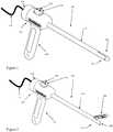
- FIGS. 1 and 2depict schematic perspective views of an embodiment of the cannula assembly 100 in closed and open positions, respectively.
- the cannula assembly 100includes a tubular element 110 forming a lumen 202.
- a proximal end 114 of the tubular element 110can be adapted for manipulation by the surgeon or clinician, and a distal end 116 can be adapted for insertion into a body cavity.
- a housing 108 with a handle 104can be attached near or at the proximal end 114 for manipulation by the surgeon or clinician.
- the tubular element 110can form a variety of cross-sectional shapes, e.g., generally round or cylindrical, ellipsoidal, triangular, square, rectangular, and D-shaped (in which one side is flat).
- All or parts of the distal end of the cannula assembly 100are capable of being positioned into a closed position 102 for insertion and extraction either directly into the body cavity or through another insufflating cannula.
- the distal end assemblyforms a pointed tip, such as a trocar capable of puncturing the patient's skin.
- the lumen 202 of the tubular element 110is can be fitted with a retractable and/or removable trocar, such as that depicted in FIGS. 9A-9C and described further hereinbelow.
- the trocaris made of solid, non-transparent material; whereas, in another embodiment all or parts of the trocar are made of optically transparent or optically transmissive material.
- At least one deployable portion 204 of the tubular element 110has an adjustable angle of deployment based on the operation of the opening adjustment means 106, i.e., an actuation mechanism.
- the adjustment means 106can move the deployable portion 204 between a closed position and an open position.
- the adjustment means 106can incrementally move the deployable portion 204 between a closed position and any number of open positions.
- the deployable portion 204houses an electronic component, which is at least partially disposed in the lumen when in the closed position.
- all electronic componentsare housed within the walls of the tubular element.
- the deployable portion 204is moved to at least one open position, the lumen 202 is substantially free from obstruction due to the electronic components being moved out of the lumen, such that various instruments, e.g., surgical tools or other electronic components, can be passed through the lumen and used during the operation or surgical procedure.
- the electronics componentsinclude one or more image transmission components 304, in combination with one or more illumination components 305.
- the image transmission component 304may be a charge-coupled device (CCD) camera, a complementary metal oxide semiconductor (CMOS) imaging device, and/or an imaging fiber optic cable, and their ancillary optics and electronic drivers for power, communication and other functions.
- CCDcharge-coupled device
- CMOScomplementary metal oxide semiconductor
- imaging fiber optic cableand their ancillary optics and electronic drivers for power, communication and other functions.
- one or more of the image transmission components 304may also image across the spectrum, including those portions invisible to the human eye, such as infrared and ultra-violet.
- two image transmission componentsmay be configured to capture stereoscopic images (in still and/or in motion).
- one or more of the image transmission components 304may be configured with any of a combination of fixed optics, adaptive optics, and/or active optics. Adaptive and active optics can be capable of focusing and/or zooming onto the image or target area.
- the one or more image transmission components 304are capable of capturing both motion and still images, and transmitting them to the surgeon or operator through wired or wireless communication means 118 housed within or connected to the housing 108, handle 104, lumen 202 and/or the tubular element 110 wall.
- Such communications means 118may include electrical signals, such as analog and/or digital, or a fiber optic communication system.
- the illumination component 305may be one or more light or illumination sources 306, 308, and their ancillary electronic drivers 310.
- the illumination sources 306, 308are Light Emitting Diodes (LED), organic LED (OLED), illumination fiber optic, filament lamps, electroluminescent and/or laser sources.
- the illumination component 305is tailored to work closely in both optical and spectrum characteristics with the image transmission component 304, with the illumination area, level, and homogeneity being optimized. In one example, this may mean the illumination level is controlled by the surgeon or clinician; whereas, in another the image transmission component Automated Gain Control (AGC) is correlated with the illumination level of the illumination component 305.
- AGCAutomated Gain Control
- the adjustment means 106may include a knob 701, which is connected to a rotational wheel 702, and links 704, 706 traveling through the lumen, along the length of the tubular element 110.
- a push rodcan be used in lieu of a knob 701.
- the links 704, 706travel through one or more longitudinal apertures formed in the wall of the tubular element 110. Turning the knob 701 causes rotation of the wheel 702 in one direction, which pulls on one end of the link 706 and transfers force to its other end, which is connected to a downstream portion 712 of a hinge 714, and opens the deployable portion 204.
- a partial turn of the knob 701can, for example, move the deployable portion 204 into any intermediate open position.
- An equivalent, but opposite turn of the knob 701pulls on link 704, which is connected to an upstream portion 710 of the hinge 714, and closes the deployable portion 204.
- the links 704may be stiff or flexible elements, such as bars, rods, cables, wires, etc. Alternatively, a nut and lead screw combination may be used.
- a levercan be used.
- a spring-loaded release mechanismcan actuate the deployable portion 204.
- the deployable portion 204can be actuated with a magnetic system.
- the deployable portion 204is fitted with a magnet (e.g., a permanent magnet or a ferromagnetic target).
- a complementary magnete.g., a permanent magnet or a electromagnet target
- an operatorcan open and close the deployable portion 204 by moving the external magnet about and in relation to the deployable portion 204.
- the hinge arrangements for the opening/closing of the deployable portions 204may be accomplished in a number of ways.
- one or more of the deployable portions 204transition between a closed and a number of open positions via a hinge arrangement.
- the hinge arrangementmay include a hinge disposed within a wall of the tubular element 110, e.g., all or partially within the lumen 202, around a pivot point, on a circumference of the tubular element 110, e.g., a circumferential hinge, and/or on an exterior of the tubular element 110.
- the hinge arrangementmay include at least one four-bar linkage.
- the lumen 202is kept clear by passing the links 704, 706 through a recess along or an aperture formed inside the tubular element 110 wall.
- the adjustment means 106include electro-mechanical actuation of switches, operated by the surgeon or clinician, that drive one or more motors.
- the motors or actuatorsmay be located either within the proximal end 114 (e.g., non-deployable portions) of the tubular element 110, or within the deployable portion 204.
- the deployable portion 204can be moved via a pneumatic or fluidic actuator.
- the hinge connecting the deployable portion 204 to the distal end 116can include Shape Memory Alloy (SMA) materials with or without an assisted heating element.
- SMAShape Memory Alloy
- any deployable portion 204can be closed at room temperature (e.g., 25°C), and deploy at the temperature less than that expected within the body cavity (e.g., less than 37°C).
- the assisted heating elementcan be controlled by the surgeon or clinician. The voltage for the assisted heating element can be transmitted along the tubular element 110 walls.
- the assisted heating elementis used to place the SMA material into the deployable temperature range once within the body cavity; for example, increasing the voltage will increase the temperature of the SMA material, which transitions the deployable portion 204 to one or more of its open positions. Removing or decreasing the voltage (and hence the heat), makes the deployable portion 204 transition to its closed position.
- the link 612is a single element, e.g., a tape or rod, made of metal or other non-buckling configuration, which when pushed towards the distal end by the surgeon via operation of the knob 701, causes it to extend towards the distal end of the lumen 604.
- the extending pressureforces the hinge arrangement 608, 614 on the deployable portion 602 to flip and to rotate into one or more open positions, causing the formerly distal facing portion 610 to now face towards the proximal end.
- the imaging component 606 and illumination component 616face the area of interest.
- the angle of opening of the deployable portion 602may be adjusted by the amount of link 612 fed into the tubular element 110 through the rotation of the knob 701 or other structural adjustment mechanism.
- This arrangementallows for the image component 606 and illumination components 616 to occupy almost or all of the lumen 604 when closed, and to leave the lumen 604 substantially open and available for instrument insertion/operation and/or removal of both instruments and body samples when open.
- this arrangementprotects any image or illumination components when closed, while allowing the same degree of triangulation by adjustment of either the opening angle for the deployable portion 602 and/or the image component 606 and illumination component 616. Similar hinge arrangements and adjustment means to those described herein may also be used.
- the hinge arrangementis a four-bar linkage with arms 802, 803 that are attached to a deployable portion 804.
- the deployable portion 804can be similarly actuated as described above.
- one or more links passing internally through the wall of the tubular element 110connect to the arms 802, 803.
- Rotation of the knob or a push of a push rodraises the deployable potion 804 above the tubular element 110.
- Imaging component 606 and illumination component 616are housed in the deployable portion 804.
- the tubular element 110can include a plurality of deployable portions, e.g., two or three deployable portions.
- one embodimentincludes two deployable portions, one deployable portion 205 with electronic components (e.g., one or more image transmission components and/or one or more illumination components), the other deployable portion 314 without electronic components.
- both deployable portions 205, 314can include electronic components.
- One or both of the deployable portions 205, 314can open in response to user input.
- the number of deployable portionsis only limited by the ability to divide the circumference of the tubular element 110, in either homogeneous or dissimilar sized portions.
- One or more such deployable portionsmay be formed, using any combination of the adjustment means discussed herein. This gives the surgeon or clinician additional freedom from cannula interference in the area where the surgery or operation is taking place.
- the deployable portion 204 containing electronic componentis actuated with mechanical links, while the other deployable portion 314, with no electronic component, uses SMA means for deployment. This would allow the fine pointing/triangulation for the deployable portion 204 with electronic components, and a simpler, less precise adjustment mechanism for the other deployable portion 314.
- a complementary set of electronicsis housed in each deployable portion 204, 314, providing system redundancy selectable by the surgeon or operator.
- the tubular element 110can include three deployable portions, one containing image transmission components, the other containing illumination components, and the last one having no electronic component. Alternatively, at least one or more of an image transmission component and an illumination component can be disposed on each of the deployable portions.
- the deployable portion(s) 204 of the tubular element 110is configured to move from the closed position aligned with the tubular element 110 (i.e., at zero degrees) into an infinite number of open positions from zero to 180 degrees relative to the centerline axis defined by the tubular element 110. This provides the surgeon or operator with the ability to effectively "triangulate" one or more of the field of views of the image transmission component and the illumination component. As may be seen in FIG. 4 , adjusting the angle ⁇ of the opening of the deployable portion 204 relative to the axis 402 of the tubular element 110, causes the direction of view 404, e.g., of the image transmission component or illumination component, to be adjusted without movement of the cannula.
- the cannulamay affect an instrument's position, vis-à-vis the organ or body structure being operated on.
- the cannulamay be rotated so that the image transmission component and the illumination component cover more fields of view.
- the rotation of the cannulacan be tracked to keep the image in one orientation.
- an accelerometer, an encoder (e.g., mechanical or optical), or other suitable feedback element disposed in the cannula assemblycan communicate with control electronics in the video output of the image transmission component to rotate the image before it is displayed to the operator, in order to maintain the image in the same orientation.
- the feedback elementmay have a fixed reference point to indicate a preferred orientation, such as a vertical or up orientation.
- the fixed reference point of the feedback elementcorresponds to a particular reference point or orientation of the image transmission component. This may be the same orientation, such as an up orientation. Rotation of the cannula can be accomplished automatically without user-intervention or the rotation can be controlled by the operator.
- imaging featuresmay be implemented, including electro-optic image stabilization and others.
- a fail-safe design feature of the cannula assemblyresults from the hinge arrangement for the deployable portion(s) 204 being located at a point upstream of the distal end 116.
- the deployable portion 204can be closed upon extraction of the cannula assembly through the force exerted on it during withdrawal through an external insertion cannula 200. In this configuration, the deployable portion 204 is moved to the closed position without operation of the adjustment means 106.
- All or part of the distal end 116 of the tubular element 110may be formed from an optically transparent material as a trocar, pointed tip, or any suitably shaped frontal form.
- a deployable or removable mirroroccupying all or part of the interior volume of the lumen 202, the surgeon or operator would be able to see a forward view beyond the cannula assembly when the deployable portion 204 is at or near the closed position.
- a prismcan be used in lieu of a mirror.
- FIGS. 5A and 5Billustrate an embodiment of the cannula assembly 100 in which all or part of the trocar is made of optically transmissive or optically transparent materials.
- the image transmission component 508is capable of imaging through the distal end 502 of the cannula assembly via an optical path 512, which travels through a window 510, light pipe, or similar optically transmissive medium on the distal end 502.
- a mirror assemblywhich can be one or more suitably reflective surfaces 506, can be placed at suitable angle(s) to permit the forward view.
- the reflective surface 506forms a connection 504 (e.g., a rod) through the lumen 202 of the cannula assembly 100 to the proximal end 114, allowing the mirror assembly to be extracted once the deployable portion 204 is opened, if necessary.
- a cannula assembly 900has the capability of forward viewing while the deployable portion 204 is in the closed position.
- the cannula assembly 900can include a removable trocar.
- the distal endforms a combination of two portions.
- Oneis a deployable portion 204 (with external surface 902) and the other is a retractable portion 904.
- the deployable portion 204may be made from any suitable material, while the retractable portion 904 is preferably made from an optically transmissive or optically transparent material.
- An optically transmissive or optically transparent materialprovides a window, that in combination with the mirror assembly inside the lumen (and similar to those described above), allows the imaging transmission component to view forward while the deployable portion 204 is in the closed position.
- retractable portion 904is retracted through the lumen by the surgeon or operator.
- additional illumination sourcesare placed within indentations in the external surface 904 facing the distal end. Such illumination sources would minimize reflections from the optically transmissive portions of the trocar coming back to the image transmission components.
- power for the illumination sourcesis provided by energy storage components placed within the cannula assembly, e.g., a battery in the handle, minimizing the interfacing to the rest of the cannula assembly. The surgeon can activate the illumination sources at the time of insertion of the cannula assembly.
- the illumination sourcemay include any of the illumination sources described above.
- the energy storage componentmay be batteries or super-capacitors. The energy storage component can be attached to the rod 504 or can be connected to the illumination sources.
Landscapes
- Health & Medical Sciences (AREA)
- Life Sciences & Earth Sciences (AREA)
- Surgery (AREA)
- Animal Behavior & Ethology (AREA)
- Public Health (AREA)
- Engineering & Computer Science (AREA)
- Biomedical Technology (AREA)
- Heart & Thoracic Surgery (AREA)
- Medical Informatics (AREA)
- Molecular Biology (AREA)
- Pathology (AREA)
- General Health & Medical Sciences (AREA)
- Nuclear Medicine, Radiotherapy & Molecular Imaging (AREA)
- Veterinary Medicine (AREA)
- Physics & Mathematics (AREA)
- Biophysics (AREA)
- Optics & Photonics (AREA)
- Radiology & Medical Imaging (AREA)
- Oral & Maxillofacial Surgery (AREA)
- Endoscopes (AREA)
Description
- The present invention relates generally to cannulas with integrated imaging and illumination devices, more particularly to those configured with a deployable portion.
- In minimally invasive surgery, there are often several small incisions made into the body to insert surgical tools, insufflation devices, endoscopes, or other viewing devices. Surgeons are now doing procedures in a manner that minimizes the number of incisions, possibly to only one, referred to as Single Port Incision or Single Port Access (SPA). Surgeons are also using natural orifices, such as the mouth, to provide access for procedures using no incision or only incisions internal to the body.
- The advantages sought by surgeons by reducing the number of incision points to as few as possible is to lessen trauma to the patient, reduce the incidence of infection, improve recovery time, and decrease cosmetic damage.
- The reduction of incision locations will change the way that surgeons and their teams work. There may no longer be room around the access point to accommodate multiple surgeons who would normally hold and adjust instruments around the surgical field. A single surgeon may need to control all of the instruments for the procedure through one access point.
- For example, endoscopic surgical procedures performed through a tubular cannula have evolved over the years. Presently, surgeons are performing endoscopic procedures in any hollow viscus of the torso body area after the region is insufflated. Typically, multiple narrow cannulas are each inserted through individual small entrance wounds (i.e., ports) in the skin, in order to accommodate various instruments, as well as varying viewing angles. To accomplish their insertion, separate trocars are used in conjunction with the cannulas to puncture the body cavity. A trocar is a guide placed inside the cannula with either a pointed cutting blade or blunt tip, depending on whether it is used to puncture the skin or enter through a separately made incision. Once the cannula is inserted, the trocar is removed, leaving the hollow cannula in place for use during the procedure.
- The entry and deployment of imaging and/or lighting components can aid surgical procedures, such as endoscopic procedures. Examples of tubular cannula with deployable imaging and/or lighting components are described in
U.S. Patent No. 5,166,787 to Irion ,U.S. Application Publication No. 2009/0275799 to Saadat et al. ,U.S. Application Publication No. 2009/0259097 to Thompson , andU.S. Application Publication. No. 2008/0065099 to Cooper et al. US 5166787 discloses an endoscope with a video device arranged at the distal end of the endoscope shaft. The video device is connected by means of a transmission system to a supply unit arranged at the proximal end of the endoscope shaft. The video device is provided with a lens and an illumination unit. The lens and the image recorder are combined into a video unit which is held in such a movable manner at the endoscope shaft that the outer contour of the cross-section of the video unit lays essentially within the outer contour of the cross-section of the distal end of the endoscope shaft when being introduced into a cavity. After the introduction procedure, the unit can be moved in relation to the distal end of the endoscopic shaft beyond the outer contour of the cross-section and/or longitudinal section.US 2003/032863 discloses an imaging probe, positioned at the distal end of the elongated member; a pivot mechanism mechanically coupled to the imaging probe; and an actuating assembly extending through the passage of the elongated member and coupled to the pivoting mechanism. The imaging probe includes an objective lens, an imager positioned to receive an image from the objective lens, and a light source for illuminating a target. Upon actuation of the actuating mechanism, the pivot mechanism rotates the imaging probe relative to a point at the distal end of the elongated member.WO 2009/006335 discloses a catheter, including a deflectable member located at a distal end of the catheter. The deflectable member comprises an ultrasound transducer array. The catheter includes a lumen extending from a proximal end of the catheter to the distal end, which is used to deliver an interventional device to a point distal to the distal end of the catheter. The deflectable member is selectively deflectable in a pivot-like manner through an arc of at least 90 degrees. The ultrasound transducer array may be operable to image both when aligned with the catheter and when pivoted relative to the catheter. When pivoted relative to the catheter, the ultrasound transducer array may have a field of view distal to the distal end of the catheter.- There is, therefore, a need in the art for a surgical apparatus assembly combining trocar cannula, with imaging and illumination capabilities, in order to minimize the number of openings in the body per procedure.
- Prior art surgical instruments lack the ability to protect the optics of both imagers and illumination during insertion and lack the ability to obtain a viewing angle that is offset from the cannula axis. One purpose of the present invention is to make it easier to control the access, imaging, and instrument use during minimally invasive surgery, when using fewer incisions than typically necessary. By combining the cannula, imaging, and illumination, a single device can take the place of several, thereby allowing more efficient and more easily controlled access.
- In one embodiment of the invention, a surgical apparatus includes combinations of trocar, cannula, and imaging and illumination components. In this embodiment, such combinations provide the surgeon with improved viewing of the surgical cavity. Alternative embodiments allow for reduced number of incisions on a patient.
- The apparatus also allows for the development of improved surgical methods including reduced number of incisions, improved imaging of the surgical cavity, and/or improved performance of surgical effectiveness.
- The invention relates to a cannula assembly comprising: a tubular element forming a lumen, the tubular element having a proximal end and a distal end adapted to be inserted into a body cavity and defining a longitudinal axis; a deployable portion of the tubular element rotatable about an axis transverse to the longitudinal axis, wherein the deployable portion is coupled to and moveable with respect to the distal end of the tubular element so as to transition between a closed position and an open position; and an electronic component mounted to the deployable portion of the tubular element, wherein the electronic component is at least partially disposed in the lumen when the deployable portion is in the closed position; wherein the deployable portion comprises a wall portion of the tubular element and forms a pointed tip at the distal end of the tubular element when the deployable portion is in the closed position.
- The open position may include a range of positions. In an embodiment, the electronic component is disposed remotely from the lumen when the deployable portion is in the open position. In another embodiment, the cannula assembly also includes a removable trocar adapted to fit into the lumen when the deployable portion is in the closed position. In another embodiment, the pointed tip includes an optically transparent material, so as to project an image through the pointed tip onto the electronic component when the deployable portion is in the closed position.
- The electronic component can be an image transmission component, an illumination component, and combinations thereof. In another embodiment, the image transmission component can be a charge-coupled device camera, a complementary metal oxide semiconductor imaging device, and a fiber optic cable. In an embodiment, the illumination component can be a light source and a fiber optic cable. In another embodiment, the light source can be a light emitting diode, an organic light emitting diode, a filament lamp, an electroluminescent source, and a laser source.
- In still another embodiment , the deployable portion of the tubular element transitions between the open position and the closed position via a hinge arrangement. In an embodiment, the hinge arrangement is disposed in the tubular element. In another embodiment, the hinge arrangement includes a pivot. In yet another embodiment, the hinge arrangement is disposed on a circumference of the tubular element. In still another embodiment, the hinge arrangement includes a circumferential hinge. In an embodiment, the hinge arrangement is disposed on an exterior of the tubular element. In another embodiment, the hinge arrangement includes at least one four-bar linkage.
- The cannula assembly may also include an actuation mechanism configured to transition the deployable portion between the closed position and the open position. In another embodiment, the actuation mechanism includes a knob disposed near the proximal end, at least one link coupled to the knob, and a hinge arrangement coupled to the at least one link and the deployable portion, such that rotation of the knob moves the deployable portion between the open position and the closed position.
- An exemplary method of using a cannula assembly includes inserting a tubular element with a lumen into a body cavity, such that the tubular element has a proximal end and a distal end, and actuating a deployable portion of the tubular element about the distal end from a closed position to an open position, such that an electronic component mounted to the deployable portion is at least partially disposed in the lumen when the deployable portion is in the closed portion and the lumen is substantially free from obstruction when the deployable portion is in the open position.
- The method of using a cannula assembly may also include using the electronic component to view a portion of the body cavity beyond the distal end. The method may also include passing at least one of a surgical tool and a second electronic component through the lumen beyond the distal end when the deployable portion is in the open position. The method of using a cannula assembly may also include first introducing an insertion cannula into the body cavity such that the tubular element is inserted through the insertion cannula. The method may also include withdrawing the cannula assembly from the body cavity through the insertion cannula such that a force exerted on the cannula assembly by the insertion cannula moves the deployable portion to the closed position.
- Other features and advantages of the present invention, as well as the invention itself, can be more fully understood from the following description of the various embodiments, when read together with the accompanying drawings, in which:
FIG. 1 depicts a schematic perspective view of a cannula assembly in a closed position, according to an embodiment of the present invention;FIG. 2 depicts a schematic perspective view of the cannula assembly ofFIG. 1 in one of its open positions;FIG. 3 depicts a close-up schematic perspective view of a tip section of the cannula assembly ofFIG. 2 ;FIG. 4 depicts a close-up schematic perspective view of another embodiment of the tip section of a cannula assembly in one of its open positions, in accordance with an embodiment of the present invention;FIGS. 5A and 5B depict schematic cross-sectional and schematic partial sectional perspective views of a tip section of a cannula assembly in which an imaging component is configured for forward viewing while the cannula assembly is in the closed position, in accordance with an embodiment of the present invention;FIG. 6 depicts a schematic perspective close-up view of another embodiment of a tip section of a cannula assembly in one of its open positions, according to an embodiment of the present invention;FIGS. 7A and7B depict schematic cross-sectional close-up and schematic perspective views of an actuating mechanism connected to a deployable portion of a cannula assembly in the open and closed positions, in accordance with an embodiment of the present invention;FIG. 8 depicts a schematic perspective close-up view of a tip section of a cannula assembly in one of its open positions, according to another embodiment of the present invention; andFIGS. 9A, 9B and9C depict schematic perspective and schematic cross-sectional views of another tip embodiment of the apparatus with the capability of forward viewing while closed and having a removable trocar, according to an embodiment of the present invention.- To provide an overall understanding of the invention, certain illustrative embodiments will now be described, including apparatus and methods for displaying images. However, it will be understood by one of ordinary skill in the art that the systems and methods described herein may be adapted and modified as is appropriate for the application being addressed and that the systems and methods described herein may be employed in other suitable applications.
FIGS. 1 and 2 depict schematic perspective views of an embodiment of thecannula assembly 100 in closed and open positions, respectively. In one embodiment, thecannula assembly 100 includes atubular element 110 forming alumen 202. Aproximal end 114 of thetubular element 110 can be adapted for manipulation by the surgeon or clinician, and adistal end 116 can be adapted for insertion into a body cavity. Ahousing 108 with ahandle 104 can be attached near or at theproximal end 114 for manipulation by the surgeon or clinician. In alternative embodiments, thetubular element 110 can form a variety of cross-sectional shapes, e.g., generally round or cylindrical, ellipsoidal, triangular, square, rectangular, and D-shaped (in which one side is flat).- All or parts of the distal end of the
cannula assembly 100 are capable of being positioned into aclosed position 102 for insertion and extraction either directly into the body cavity or through another insufflating cannula. When closed, the distal end assembly forms a pointed tip, such as a trocar capable of puncturing the patient's skin. In another embodiment, thelumen 202 of thetubular element 110 is can be fitted with a retractable and/or removable trocar, such as that depicted inFIGS. 9A-9C and described further hereinbelow. In one embodiment, the trocar is made of solid, non-transparent material; whereas, in another embodiment all or parts of the trocar are made of optically transparent or optically transmissive material. - One or more portions of the
distal end 116 of thetubular element 110 may be designed to open once inserted into the body cavity. In one embodiment, as depicted inFIG. 3 , at least onedeployable portion 204 of thetubular element 110 has an adjustable angle of deployment based on the operation of the opening adjustment means 106, i.e., an actuation mechanism. For example, the adjustment means 106 can move thedeployable portion 204 between a closed position and an open position. Alternatively, the adjustment means 106 can incrementally move thedeployable portion 204 between a closed position and any number of open positions. In additional or alternative embodiments, thedeployable portion 204 houses an electronic component, which is at least partially disposed in the lumen when in the closed position. In an alternative embodiment, all electronic components are housed within the walls of the tubular element. When thedeployable portion 204 is moved to at least one open position, thelumen 202 is substantially free from obstruction due to the electronic components being moved out of the lumen, such that various instruments, e.g., surgical tools or other electronic components, can be passed through the lumen and used during the operation or surgical procedure. - The electronics components include one or more
image transmission components 304, in combination with one ormore illumination components 305. In one embodiment, theimage transmission component 304 may be a charge-coupled device (CCD) camera, a complementary metal oxide semiconductor (CMOS) imaging device, and/or an imaging fiber optic cable, and their ancillary optics and electronic drivers for power, communication and other functions. - Optically, one or more of the
image transmission components 304 may also image across the spectrum, including those portions invisible to the human eye, such as infrared and ultra-violet. In one embodiment, two image transmission components may be configured to capture stereoscopic images (in still and/or in motion). In one embodiment, one or more of theimage transmission components 304 may be configured with any of a combination of fixed optics, adaptive optics, and/or active optics. Adaptive and active optics can be capable of focusing and/or zooming onto the image or target area. - In one embodiment, the one or more
image transmission components 304 are capable of capturing both motion and still images, and transmitting them to the surgeon or operator through wired or wireless communication means 118 housed within or connected to thehousing 108, handle 104,lumen 202 and/or thetubular element 110 wall. Such communications means 118 may include electrical signals, such as analog and/or digital, or a fiber optic communication system. - The
illumination component 305 may be one or more light orillumination sources electronic drivers 310. In one embodiment, theillumination sources illumination component 305 is tailored to work closely in both optical and spectrum characteristics with theimage transmission component 304, with the illumination area, level, and homogeneity being optimized. In one example, this may mean the illumination level is controlled by the surgeon or clinician; whereas, in another the image transmission component Automated Gain Control (AGC) is correlated with the illumination level of theillumination component 305. - In one embodiment, as depicted in
FIGS. 7A and7B , the adjustment means 106 may include aknob 701, which is connected to arotational wheel 702, and links 704, 706 traveling through the lumen, along the length of thetubular element 110. In an alternative embodiment, a push rod can be used in lieu of aknob 701. In another alternative embodiment, thelinks tubular element 110. Turning theknob 701 causes rotation of thewheel 702 in one direction, which pulls on one end of thelink 706 and transfers force to its other end, which is connected to adownstream portion 712 of ahinge 714, and opens thedeployable portion 204. A partial turn of theknob 701 can, for example, move thedeployable portion 204 into any intermediate open position. An equivalent, but opposite turn of theknob 701 pulls onlink 704, which is connected to anupstream portion 710 of thehinge 714, and closes thedeployable portion 204. Thelinks 704 may be stiff or flexible elements, such as bars, rods, cables, wires, etc. Alternatively, a nut and lead screw combination may be used. Instead of theknob 701, a lever can be used. Similarly, instead of theknob 701, a spring-loaded release mechanism can actuate thedeployable portion 204. In an alternative embodiment, thedeployable portion 204 can be actuated with a magnetic system. In this configuration, thedeployable portion 204 is fitted with a magnet (e.g., a permanent magnet or a ferromagnetic target). A complementary magnet (e.g., a permanent magnet or a electromagnet target) external to the body or patient is used to interact with the magnet on thedeployable portion 204, such that an operator can open and close thedeployable portion 204 by moving the external magnet about and in relation to thedeployable portion 204. - The hinge arrangements for the opening/closing of the
deployable portions 204 may be accomplished in a number of ways. In one embodiment, one or more of thedeployable portions 204 transition between a closed and a number of open positions via a hinge arrangement. The hinge arrangement may include a hinge disposed within a wall of thetubular element 110, e.g., all or partially within thelumen 202, around a pivot point, on a circumference of thetubular element 110, e.g., a circumferential hinge, and/or on an exterior of thetubular element 110. Alternatively, the hinge arrangement may include at least one four-bar linkage. - In an alternative embodiment, the
lumen 202 is kept clear by passing thelinks tubular element 110 wall. In an alternative embodiment, the adjustment means 106 include electro-mechanical actuation of switches, operated by the surgeon or clinician, that drive one or more motors. The motors or actuators may be located either within the proximal end 114 (e.g., non-deployable portions) of thetubular element 110, or within thedeployable portion 204. Alternatively, thedeployable portion 204 can be moved via a pneumatic or fluidic actuator. - In an alternative embodiment, the hinge connecting the
deployable portion 204 to thedistal end 116 can include Shape Memory Alloy (SMA) materials with or without an assisted heating element. In one embodiment, using a material such as Nitinol (located within thelumen 202,tubular element 110 and/or the deployable portion 204), anydeployable portion 204 can be closed at room temperature (e.g., 25°C), and deploy at the temperature less than that expected within the body cavity (e.g., less than 37°C). In an alternative embodiment, the assisted heating element can be controlled by the surgeon or clinician. The voltage for the assisted heating element can be transmitted along thetubular element 110 walls. The assisted heating element is used to place the SMA material into the deployable temperature range once within the body cavity; for example, increasing the voltage will increase the temperature of the SMA material, which transitions thedeployable portion 204 to one or more of its open positions. Removing or decreasing the voltage (and hence the heat), makes thedeployable portion 204 transition to its closed position. - In one embodiment, as depicted in
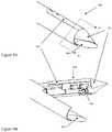
FIG. 6 , thelink 612 is a single element, e.g., a tape or rod, made of metal or other non-buckling configuration, which when pushed towards the distal end by the surgeon via operation of theknob 701, causes it to extend towards the distal end of thelumen 604. The extending pressure forces thehinge arrangement deployable portion 602 to flip and to rotate into one or more open positions, causing the formerly distal facingportion 610 to now face towards the proximal end. In this configuration, theimaging component 606 andillumination component 616 face the area of interest. The angle of opening of thedeployable portion 602 may be adjusted by the amount oflink 612 fed into thetubular element 110 through the rotation of theknob 701 or other structural adjustment mechanism. This arrangement allows for theimage component 606 andillumination components 616 to occupy almost or all of thelumen 604 when closed, and to leave thelumen 604 substantially open and available for instrument insertion/operation and/or removal of both instruments and body samples when open. In addition, this arrangement protects any image or illumination components when closed, while allowing the same degree of triangulation by adjustment of either the opening angle for thedeployable portion 602 and/or theimage component 606 andillumination component 616. Similar hinge arrangements and adjustment means to those described herein may also be used. - In an alternative embodiment, as depicted in
FIG. 8 , the hinge arrangement is a four-bar linkage witharms deployable portion 804. In this arrangement, thedeployable portion 804 can be similarly actuated as described above. For example, one or more links passing internally through the wall of thetubular element 110 connect to thearms deployable potion 804 above thetubular element 110.Imaging component 606 andillumination component 616 are housed in thedeployable portion 804. - In an alternative embodiment, as depicted in
FIG. 4 , thetubular element 110 can include a plurality of deployable portions, e.g., two or three deployable portions. For example, as shown inFIG. 4 , one embodiment includes two deployable portions, one deployable portion 205 with electronic components (e.g., one or more image transmission components and/or one or more illumination components), the otherdeployable portion 314 without electronic components. Alternatively, bothdeployable portions 205, 314 can include electronic components. One or both of thedeployable portions 205, 314 can open in response to user input. The number of deployable portions is only limited by the ability to divide the circumference of thetubular element 110, in either homogeneous or dissimilar sized portions. One or more such deployable portions may be formed, using any combination of the adjustment means discussed herein. This gives the surgeon or clinician additional freedom from cannula interference in the area where the surgery or operation is taking place. - In one embodiment, the
deployable portion 204 containing electronic component is actuated with mechanical links, while the otherdeployable portion 314, with no electronic component, uses SMA means for deployment. This would allow the fine pointing/triangulation for thedeployable portion 204 with electronic components, and a simpler, less precise adjustment mechanism for the otherdeployable portion 314. In another embodiment, a complementary set of electronics is housed in eachdeployable portion tubular element 110 can include three deployable portions, one containing image transmission components, the other containing illumination components, and the last one having no electronic component. Alternatively, at least one or more of an image transmission component and an illumination component can be disposed on each of the deployable portions. - The deployable portion(s) 204 of the
tubular element 110 is configured to move from the closed position aligned with the tubular element 110 (i.e., at zero degrees) into an infinite number of open positions from zero to 180 degrees relative to the centerline axis defined by thetubular element 110. This provides the surgeon or operator with the ability to effectively "triangulate" one or more of the field of views of the image transmission component and the illumination component. As may be seen inFIG. 4 , adjusting the angle α of the opening of thedeployable portion 204 relative to theaxis 402 of thetubular element 110, causes the direction ofview 404, e.g., of the image transmission component or illumination component, to be adjusted without movement of the cannula. This allows the view to be changed slightly, without reverting to the need to move the cannula. During a procedure, moving the cannula may affect an instrument's position, vis-à-vis the organ or body structure being operated on. In use, the cannula may be rotated so that the image transmission component and the illumination component cover more fields of view. The rotation of the cannula can be tracked to keep the image in one orientation. In various embodiments, an accelerometer, an encoder (e.g., mechanical or optical), or other suitable feedback element disposed in the cannula assembly can communicate with control electronics in the video output of the image transmission component to rotate the image before it is displayed to the operator, in order to maintain the image in the same orientation. The feedback element may have a fixed reference point to indicate a preferred orientation, such as a vertical or up orientation. The fixed reference point of the feedback element corresponds to a particular reference point or orientation of the image transmission component. This may be the same orientation, such as an up orientation. Rotation of the cannula can be accomplished automatically without user-intervention or the rotation can be controlled by the operator. Within the image transmission component, well known and understood imaging features may be implemented, including electro-optic image stabilization and others. - A fail-safe design feature of the cannula assembly results from the hinge arrangement for the deployable portion(s) 204 being located at a point upstream of the
distal end 116. Thedeployable portion 204 can be closed upon extraction of the cannula assembly through the force exerted on it during withdrawal through anexternal insertion cannula 200. In this configuration, thedeployable portion 204 is moved to the closed position without operation of the adjustment means 106. - All or part of the
distal end 116 of thetubular element 110 may be formed from an optically transparent material as a trocar, pointed tip, or any suitably shaped frontal form. In combination with a deployable or removable mirror occupying all or part of the interior volume of thelumen 202, the surgeon or operator would be able to see a forward view beyond the cannula assembly when thedeployable portion 204 is at or near the closed position. In an alternative embodiment, a prism can be used in lieu of a mirror. FIGS. 5A and 5B illustrate an embodiment of thecannula assembly 100 in which all or part of the trocar is made of optically transmissive or optically transparent materials. When thedeployable portion 204 is in aclosed position 500, theimage transmission component 508 is capable of imaging through thedistal end 502 of the cannula assembly via anoptical path 512, which travels through awindow 510, light pipe, or similar optically transmissive medium on thedistal end 502.- Within the lumen, a mirror assembly, which can be one or more suitably
reflective surfaces 506, can be placed at suitable angle(s) to permit the forward view. Thereflective surface 506 forms a connection 504 (e.g., a rod) through thelumen 202 of thecannula assembly 100 to theproximal end 114, allowing the mirror assembly to be extracted once thedeployable portion 204 is opened, if necessary. - As depicted in
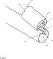
FIGS. 9A, 9B and9C , acannula assembly 900 has the capability of forward viewing while thedeployable portion 204 is in the closed position. In addition, thecannula assembly 900 can include a removable trocar. The distal end forms a combination of two portions. One is a deployable portion 204 (with external surface 902) and the other is aretractable portion 904. Thedeployable portion 204 may be made from any suitable material, while theretractable portion 904 is preferably made from an optically transmissive or optically transparent material. An optically transmissive or optically transparent material provides a window, that in combination with the mirror assembly inside the lumen (and similar to those described above), allows the imaging transmission component to view forward while thedeployable portion 204 is in the closed position. Upon deployment,retractable portion 904 is retracted through the lumen by the surgeon or operator. - In one embodiment, additional illumination sources are placed within indentations in the
external surface 904 facing the distal end. Such illumination sources would minimize reflections from the optically transmissive portions of the trocar coming back to the image transmission components. In an alternative embodiment, power for the illumination sources is provided by energy storage components placed within the cannula assembly, e.g., a battery in the handle, minimizing the interfacing to the rest of the cannula assembly. The surgeon can activate the illumination sources at the time of insertion of the cannula assembly. The illumination source may include any of the illumination sources described above. The energy storage component may be batteries or super-capacitors. The energy storage component can be attached to therod 504 or can be connected to the illumination sources. - Various embodiments and features of the present invention have been described in detail with a certain degree of particularity. The utilities thereof can be appreciated by those skilled in the art. It should be emphasized that the above-described embodiments of the present invention merely describe possible examples of the implementations to set forth a clear understanding of the principles of the invention, and that numerous changes, variations, and modifications can be made to the embodiments described herein without departing from the scope of the invention. Also, such variations and modifications are intended to be included herein within the scope of the present invention, as set forth in the appended claims. The scope of the present invention is defined by the appended claims, rather than the forgoing description of embodiments.
Claims (12)
- A cannula assembly (100) comprising:a tubular element (110) forming a lumen (202), the tubular element (110) having a proximal end (114) and a distal end (116) adapted to be inserted into a body cavity and defining a longitudinal axis (402);a deployable portion (204) of the tubular element (110) rotatable about an axis transverse to the longitudinal axis (402), wherein the deployable portion (204) is coupled to and moveable with respect to the distal end (116) of the tubular element (110) so as to transition between a closed position (102) and an open position; andan electronic component mounted to the deployable portion (204) of the tubular element (110), wherein the electronic component is at least partially disposed in the lumen (202) when the deployable portion (204) is in the closed position (102);wherein the deployable portion (204) comprises a wall portion of the tubular element (110) and forms a pointed tip at the distal end (116) of the tubular element (110) when the deployable portion (204) is in the closed position (102).
- The cannula assembly (100) of claim 1, wherein the open position comprises a range of positions.
- The cannula assembly (100) of claim 1, wherein the electronic component is disposed remotely from the lumen (202) when the deployable portion (204) is in the open position.
- The cannula assembly (100) of claim 1 further comprising a removable trocar adapted to fit into the lumen (202) when the deployable portion (204) is in the closed position (102).
- The cannula assembly (100) of claim 1, wherein the pointed tip of the deployable portion (204) comprises an optically transparent material, so as to project an image through the pointed tip onto the electronic component when the deployable portion (204) is in the closed position (102).
- The cannula assembly (100) of claim 1, wherein the electronic component is selected from the group consisting of an image transmission component (304), an illumination component (305), and combinations thereof.
- The cannula assembly (100) of claim 6, wherein:-(i) the image transmission component (304) is selected from the group consisting of a charge-coupled device camera, a complementary metal oxide semiconductor imaging device, and a fiber optic cable; or(ii) the illumination component (305) is selected from the group consisting of a light source and a fiber optic cable; and optionally or preferablywherein the light source is selected from the group consisting of a light emitting diode, an organic light emitting diode, a filament lamp, an electroluminescent source, and a laser source.
- The cannula assembly (100) of claim 1, wherein the deployable portion (204) of the tubular element (110) transitions between the open position and the closed position (102) via a hinge arrangement.
- The cannula assembly (100) of claim 8, wherein:-(i) the hinge arrangement is disposed in the tubular element, and optionally or preferably
wherein the hinge arrangement comprises a pivot; or(ii) wherein the hinge arrangement is disposed on a circumference of the tubular element, and optionally or preferablywherein the hinge arrangement comprises a circumferential hinge. - The cannula assembly (100) of claim 8, wherein the hinge arrangement is disposed on an exterior of the tubular element, and optionally or preferably
wherein the hinge arrangement comprises at least one four-bar linkage. - The cannula assembly (100) of claim 1 further comprising an actuation mechanism (106) configured to transition the deployable portion (204) between the closed position (102) and the open position.
- The cannula assembly (100) of claim 11, wherein the actuation mechanism (106) comprises:a knob (701) disposed near the proximal end; at least one link (704, 706) coupled to the knob (701); anda hinge arrangement coupled to the at least one link (704, 706) and the deployable portion (204), wherein rotation of the knob (701) moves the deployable portion (204) between the open position and the closed position (102).
Applications Claiming Priority (3)
| Application Number | Priority Date | Filing Date | Title |
|---|---|---|---|
| US16421509P | 2009-03-27 | 2009-03-27 | |
| US26191009P | 2009-11-17 | 2009-11-17 | |
| PCT/US2010/028881WO2010111629A2 (en) | 2009-03-27 | 2010-03-26 | Cannula with integrated camera and illumination |
Publications (3)
| Publication Number | Publication Date |
|---|---|
| EP2410935A2 EP2410935A2 (en) | 2012-02-01 |
| EP2410935A4 EP2410935A4 (en) | 2016-09-07 |
| EP2410935B1true EP2410935B1 (en) | 2019-11-13 |
Family
ID=42781919
Family Applications (1)
| Application Number | Title | Priority Date | Filing Date |
|---|---|---|---|
| EP10756938.6AActiveEP2410935B1 (en) | 2009-03-27 | 2010-03-26 | Cannula with integrated camera and illumination |
Country Status (9)
| Country | Link |
|---|---|
| US (1) | US8439830B2 (en) |
| EP (1) | EP2410935B1 (en) |
| JP (1) | JP2012521811A (en) |
| CN (1) | CN102421384B (en) |
| AU (1) | AU2010229709B2 (en) |
| BR (1) | BRPI1009863B8 (en) |
| CA (1) | CA2756787C (en) |
| ES (1) | ES2762203T3 (en) |
| WO (1) | WO2010111629A2 (en) |
Families Citing this family (354)
| Publication number | Priority date | Publication date | Assignee | Title |
|---|---|---|---|---|
| US9060770B2 (en) | 2003-05-20 | 2015-06-23 | Ethicon Endo-Surgery, Inc. | Robotically-driven surgical instrument with E-beam driver |
| US20070084897A1 (en) | 2003-05-20 | 2007-04-19 | Shelton Frederick E Iv | Articulating surgical stapling instrument incorporating a two-piece e-beam firing mechanism |
| US9072535B2 (en) | 2011-05-27 | 2015-07-07 | Ethicon Endo-Surgery, Inc. | Surgical stapling instruments with rotatable staple deployment arrangements |
| US11890012B2 (en) | 2004-07-28 | 2024-02-06 | Cilag Gmbh International | Staple cartridge comprising cartridge body and attached support |
| US10159482B2 (en) | 2005-08-31 | 2018-12-25 | Ethicon Llc | Fastener cartridge assembly comprising a fixed anvil and different staple heights |
| US11484312B2 (en) | 2005-08-31 | 2022-11-01 | Cilag Gmbh International | Staple cartridge comprising a staple driver arrangement |
| US7669746B2 (en) | 2005-08-31 | 2010-03-02 | Ethicon Endo-Surgery, Inc. | Staple cartridges for forming staples having differing formed staple heights |
| US11246590B2 (en) | 2005-08-31 | 2022-02-15 | Cilag Gmbh International | Staple cartridge including staple drivers having different unfired heights |
| US7934630B2 (en) | 2005-08-31 | 2011-05-03 | Ethicon Endo-Surgery, Inc. | Staple cartridges for forming staples having differing formed staple heights |
| US20070106317A1 (en) | 2005-11-09 | 2007-05-10 | Shelton Frederick E Iv | Hydraulically and electrically actuated articulation joints for surgical instruments |
| US11278279B2 (en) | 2006-01-31 | 2022-03-22 | Cilag Gmbh International | Surgical instrument assembly |
| US7753904B2 (en) | 2006-01-31 | 2010-07-13 | Ethicon Endo-Surgery, Inc. | Endoscopic surgical instrument with a handle that can articulate with respect to the shaft |
| US11224427B2 (en) | 2006-01-31 | 2022-01-18 | Cilag Gmbh International | Surgical stapling system including a console and retraction assembly |
| US20120292367A1 (en) | 2006-01-31 | 2012-11-22 | Ethicon Endo-Surgery, Inc. | Robotically-controlled end effector |
| US8820603B2 (en) | 2006-01-31 | 2014-09-02 | Ethicon Endo-Surgery, Inc. | Accessing data stored in a memory of a surgical instrument |
| US8708213B2 (en) | 2006-01-31 | 2014-04-29 | Ethicon Endo-Surgery, Inc. | Surgical instrument having a feedback system |
| US8186555B2 (en) | 2006-01-31 | 2012-05-29 | Ethicon Endo-Surgery, Inc. | Motor-driven surgical cutting and fastening instrument with mechanical closure system |
| US20110295295A1 (en) | 2006-01-31 | 2011-12-01 | Ethicon Endo-Surgery, Inc. | Robotically-controlled surgical instrument having recording capabilities |
| US11793518B2 (en) | 2006-01-31 | 2023-10-24 | Cilag Gmbh International | Powered surgical instruments with firing system lockout arrangements |
| US7845537B2 (en) | 2006-01-31 | 2010-12-07 | Ethicon Endo-Surgery, Inc. | Surgical instrument having recording capabilities |
| US8992422B2 (en) | 2006-03-23 | 2015-03-31 | Ethicon Endo-Surgery, Inc. | Robotically-controlled endoscopic accessory channel |
| US8322455B2 (en) | 2006-06-27 | 2012-12-04 | Ethicon Endo-Surgery, Inc. | Manually driven surgical cutting and fastening instrument |
| US10568652B2 (en) | 2006-09-29 | 2020-02-25 | Ethicon Llc | Surgical staples having attached drivers of different heights and stapling instruments for deploying the same |
| US11980366B2 (en) | 2006-10-03 | 2024-05-14 | Cilag Gmbh International | Surgical instrument |
| US8684253B2 (en) | 2007-01-10 | 2014-04-01 | Ethicon Endo-Surgery, Inc. | Surgical instrument with wireless communication between a control unit of a robotic system and remote sensor |
| US11291441B2 (en) | 2007-01-10 | 2022-04-05 | Cilag Gmbh International | Surgical instrument with wireless communication between control unit and remote sensor |
| US8632535B2 (en) | 2007-01-10 | 2014-01-21 | Ethicon Endo-Surgery, Inc. | Interlock and surgical instrument including same |
| US20080169333A1 (en) | 2007-01-11 | 2008-07-17 | Shelton Frederick E | Surgical stapler end effector with tapered distal end |
| US7673782B2 (en) | 2007-03-15 | 2010-03-09 | Ethicon Endo-Surgery, Inc. | Surgical stapling instrument having a releasable buttress material |
| US8931682B2 (en) | 2007-06-04 | 2015-01-13 | Ethicon Endo-Surgery, Inc. | Robotically-controlled shaft based rotary drive systems for surgical instruments |
| US11564682B2 (en) | 2007-06-04 | 2023-01-31 | Cilag Gmbh International | Surgical stapler device |
| US7753245B2 (en) | 2007-06-22 | 2010-07-13 | Ethicon Endo-Surgery, Inc. | Surgical stapling instruments |
| US11849941B2 (en) | 2007-06-29 | 2023-12-26 | Cilag Gmbh International | Staple cartridge having staple cavities extending at a transverse angle relative to a longitudinal cartridge axis |
| JP5410110B2 (en) | 2008-02-14 | 2014-02-05 | エシコン・エンド−サージェリィ・インコーポレイテッド | Surgical cutting / fixing instrument with RF electrode |
| US8636736B2 (en) | 2008-02-14 | 2014-01-28 | Ethicon Endo-Surgery, Inc. | Motorized surgical cutting and fastening instrument |
| US9179912B2 (en) | 2008-02-14 | 2015-11-10 | Ethicon Endo-Surgery, Inc. | Robotically-controlled motorized surgical cutting and fastening instrument |
| US7819298B2 (en) | 2008-02-14 | 2010-10-26 | Ethicon Endo-Surgery, Inc. | Surgical stapling apparatus with control features operable with one hand |
| US7866527B2 (en) | 2008-02-14 | 2011-01-11 | Ethicon Endo-Surgery, Inc. | Surgical stapling apparatus with interlockable firing system |
| US8573465B2 (en) | 2008-02-14 | 2013-11-05 | Ethicon Endo-Surgery, Inc. | Robotically-controlled surgical end effector system with rotary actuated closure systems |
| US11986183B2 (en) | 2008-02-14 | 2024-05-21 | Cilag Gmbh International | Surgical cutting and fastening instrument comprising a plurality of sensors to measure an electrical parameter |
| US9585657B2 (en) | 2008-02-15 | 2017-03-07 | Ethicon Endo-Surgery, Llc | Actuator for releasing a layer of material from a surgical end effector |
| US11648005B2 (en) | 2008-09-23 | 2023-05-16 | Cilag Gmbh International | Robotically-controlled motorized surgical instrument with an end effector |
| US9005230B2 (en) | 2008-09-23 | 2015-04-14 | Ethicon Endo-Surgery, Inc. | Motorized surgical instrument |
| US8210411B2 (en) | 2008-09-23 | 2012-07-03 | Ethicon Endo-Surgery, Inc. | Motor-driven surgical cutting instrument |
| US9386983B2 (en) | 2008-09-23 | 2016-07-12 | Ethicon Endo-Surgery, Llc | Robotically-controlled motorized surgical instrument |
| US8608045B2 (en) | 2008-10-10 | 2013-12-17 | Ethicon Endo-Sugery, Inc. | Powered surgical cutting and stapling apparatus with manually retractable firing system |
| GB0920938D0 (en)* | 2009-11-30 | 2010-01-13 | Imp Innovations Ltd | Steerable probes |
| US8220688B2 (en) | 2009-12-24 | 2012-07-17 | Ethicon Endo-Surgery, Inc. | Motor-driven surgical cutting instrument with electric actuator directional control assembly |
| CA2743187A1 (en)* | 2010-06-11 | 2011-12-11 | The Hospital For Sick Children | Folding endoscope and method of using the same |
| US8783543B2 (en) | 2010-07-30 | 2014-07-22 | Ethicon Endo-Surgery, Inc. | Tissue acquisition arrangements and methods for surgical stapling devices |
| MX350734B (en) | 2010-09-08 | 2017-09-15 | Covidien Lp | Catheter with imaging assembly. |
| US11298125B2 (en) | 2010-09-30 | 2022-04-12 | Cilag Gmbh International | Tissue stapler having a thickness compensator |
| US9629814B2 (en) | 2010-09-30 | 2017-04-25 | Ethicon Endo-Surgery, Llc | Tissue thickness compensator configured to redistribute compressive forces |
| US9016542B2 (en) | 2010-09-30 | 2015-04-28 | Ethicon Endo-Surgery, Inc. | Staple cartridge comprising compressible distortion resistant components |
| US9788834B2 (en) | 2010-09-30 | 2017-10-17 | Ethicon Llc | Layer comprising deployable attachment members |
| US11812965B2 (en) | 2010-09-30 | 2023-11-14 | Cilag Gmbh International | Layer of material for a surgical end effector |
| US9386988B2 (en) | 2010-09-30 | 2016-07-12 | Ethicon End-Surgery, LLC | Retainer assembly including a tissue thickness compensator |
| US9351730B2 (en) | 2011-04-29 | 2016-05-31 | Ethicon Endo-Surgery, Llc | Tissue thickness compensator comprising channels |
| US12213666B2 (en) | 2010-09-30 | 2025-02-04 | Cilag Gmbh International | Tissue thickness compensator comprising layers |
| US10945731B2 (en) | 2010-09-30 | 2021-03-16 | Ethicon Llc | Tissue thickness compensator comprising controlled release and expansion |
| US11925354B2 (en) | 2010-09-30 | 2024-03-12 | Cilag Gmbh International | Staple cartridge comprising staples positioned within a compressible portion thereof |
| US8695866B2 (en) | 2010-10-01 | 2014-04-15 | Ethicon Endo-Surgery, Inc. | Surgical instrument having a power control circuit |
| US20120197078A1 (en)* | 2011-01-31 | 2012-08-02 | Eric Stanley | Insufflation needle with integrated image sensor |
| AU2012250197B2 (en) | 2011-04-29 | 2017-08-10 | Ethicon Endo-Surgery, Inc. | Staple cartridge comprising staples positioned within a compressible portion thereof |
| US11207064B2 (en) | 2011-05-27 | 2021-12-28 | Cilag Gmbh International | Automated end effector component reloading system for use with a robotic system |
| US20130046137A1 (en)* | 2011-08-15 | 2013-02-21 | Intuitive Surgical Operations, Inc. | Surgical instrument and method with multiple image capture sensors |
| US10244927B2 (en) | 2011-12-29 | 2019-04-02 | Cook Medical Technologies Llc | Space-optimized visualization catheter with camera train holder |
| EP2797490B1 (en) | 2011-12-29 | 2016-11-09 | Cook Medical Technologies LLC | Space-optimized visualization catheter having a camera train holder in a catheter with off-centered lumens |
| US20130172673A1 (en)* | 2011-12-29 | 2013-07-04 | Cook Medical Technologies Llc | Space-optimized visualization catheter |
| US9668643B2 (en) | 2011-12-29 | 2017-06-06 | Cook Medical Technologies Llc | Space-optimized visualization catheter with oblong shape |
| GB2502767B (en)* | 2012-03-21 | 2017-12-06 | Knight Martin | Cannula |
| BR112014024098B1 (en) | 2012-03-28 | 2021-05-25 | Ethicon Endo-Surgery, Inc. | staple cartridge |
| MX358135B (en) | 2012-03-28 | 2018-08-06 | Ethicon Endo Surgery Inc | Tissue thickness compensator comprising a plurality of layers. |
| US10166039B2 (en)* | 2012-04-20 | 2019-01-01 | Sanovas Intellectual Property, Llc | Viewing trocar |
| US9101358B2 (en) | 2012-06-15 | 2015-08-11 | Ethicon Endo-Surgery, Inc. | Articulatable surgical instrument comprising a firing drive |
| US9615728B2 (en) | 2012-06-27 | 2017-04-11 | Camplex, Inc. | Surgical visualization system with camera tracking |
| US9642606B2 (en) | 2012-06-27 | 2017-05-09 | Camplex, Inc. | Surgical visualization system |
| US9289256B2 (en) | 2012-06-28 | 2016-03-22 | Ethicon Endo-Surgery, Llc | Surgical end effectors having angled tissue-contacting surfaces |
| US9282974B2 (en) | 2012-06-28 | 2016-03-15 | Ethicon Endo-Surgery, Llc | Empty clip cartridge lockout |
| US12383267B2 (en) | 2012-06-28 | 2025-08-12 | Cilag Gmbh International | Robotically powered surgical device with manually-actuatable reversing system |
| US9408606B2 (en) | 2012-06-28 | 2016-08-09 | Ethicon Endo-Surgery, Llc | Robotically powered surgical device with manually-actuatable reversing system |
| US20140001231A1 (en) | 2012-06-28 | 2014-01-02 | Ethicon Endo-Surgery, Inc. | Firing system lockout arrangements for surgical instruments |
| US11278284B2 (en) | 2012-06-28 | 2022-03-22 | Cilag Gmbh International | Rotary drive arrangements for surgical instruments |
| BR112014032776B1 (en) | 2012-06-28 | 2021-09-08 | Ethicon Endo-Surgery, Inc | SURGICAL INSTRUMENT SYSTEM AND SURGICAL KIT FOR USE WITH A SURGICAL INSTRUMENT SYSTEM |
| USD735343S1 (en) | 2012-09-07 | 2015-07-28 | Covidien Lp | Console |
| US9517184B2 (en) | 2012-09-07 | 2016-12-13 | Covidien Lp | Feeding tube with insufflation device and related methods therefor |
| USD717340S1 (en) | 2012-09-07 | 2014-11-11 | Covidien Lp | Display screen with enteral feeding icon |
| US9198835B2 (en) | 2012-09-07 | 2015-12-01 | Covidien Lp | Catheter with imaging assembly with placement aid and related methods therefor |
| USD716841S1 (en) | 2012-09-07 | 2014-11-04 | Covidien Lp | Display screen with annotate file icon |
| DE102012219434A1 (en)* | 2012-10-24 | 2014-04-24 | Olympus Winter & Ibe Gmbh | Endoscope with lateral illumination, use and procedure |
| DE102012025102A1 (en)* | 2012-12-20 | 2014-06-26 | avateramedical GmBH | Endoscope with a multi-camera system for minimally invasive surgery |
| JP5949592B2 (en)* | 2013-02-14 | 2016-07-06 | ソニー株式会社 | Endoscope and endoscope apparatus |
| RU2672520C2 (en) | 2013-03-01 | 2018-11-15 | Этикон Эндо-Серджери, Инк. | Hingedly turnable surgical instruments with conducting ways for signal transfer |
| BR112015021082B1 (en) | 2013-03-01 | 2022-05-10 | Ethicon Endo-Surgery, Inc | surgical instrument |
| US9782159B2 (en) | 2013-03-13 | 2017-10-10 | Camplex, Inc. | Surgical visualization systems |
| US9629629B2 (en) | 2013-03-14 | 2017-04-25 | Ethicon Endo-Surgey, LLC | Control systems for surgical instruments |
| CN105050527B (en) | 2013-03-15 | 2018-03-27 | 圣纳普医疗(巴巴多斯)公司 | Intelligent positioning system and method therefor |
| MY177299A (en) | 2013-03-15 | 2020-09-11 | Synaptive Medical Inc | Surgical imaging systems |
| CA2902592C (en) | 2013-03-15 | 2023-03-07 | Synaptive Medical (Barbados) Inc. | Insert imaging device for surgical procedures |
| US9788906B2 (en) | 2013-03-15 | 2017-10-17 | Synaptive Medical (Barbados) Inc. | Context aware surgical systems for intraoperatively configuring imaging devices |
| US9826976B2 (en) | 2013-04-16 | 2017-11-28 | Ethicon Llc | Motor driven surgical instruments with lockable dual drive shafts |
| BR112015026109B1 (en) | 2013-04-16 | 2022-02-22 | Ethicon Endo-Surgery, Inc | surgical instrument |
| KR102195714B1 (en)* | 2013-05-02 | 2020-12-28 | 삼성전자주식회사 | Trocar for surgery and method for obtaining image using the same |
| KR102107402B1 (en)* | 2013-05-03 | 2020-05-07 | 삼성전자주식회사 | Endoscope and image processing apparatus using the endoscope |
| MX369362B (en) | 2013-08-23 | 2019-11-06 | Ethicon Endo Surgery Llc | Firing member retraction devices for powered surgical instruments. |
| US9775609B2 (en) | 2013-08-23 | 2017-10-03 | Ethicon Llc | Tamper proof circuit for surgical instrument battery pack |
| US10028651B2 (en) | 2013-09-20 | 2018-07-24 | Camplex, Inc. | Surgical visualization systems and displays |
| EP3046458B1 (en) | 2013-09-20 | 2020-10-21 | Camplex, Inc. | Surgical visualization systems |
| US10013049B2 (en) | 2014-03-26 | 2018-07-03 | Ethicon Llc | Power management through sleep options of segmented circuit and wake up control |
| BR112016021943B1 (en) | 2014-03-26 | 2022-06-14 | Ethicon Endo-Surgery, Llc | SURGICAL INSTRUMENT FOR USE BY AN OPERATOR IN A SURGICAL PROCEDURE |
| US12232723B2 (en) | 2014-03-26 | 2025-02-25 | Cilag Gmbh International | Systems and methods for controlling a segmented circuit |
| US20150272580A1 (en) | 2014-03-26 | 2015-10-01 | Ethicon Endo-Surgery, Inc. | Verification of number of battery exchanges/procedure count |
| BR112016023825B1 (en) | 2014-04-16 | 2022-08-02 | Ethicon Endo-Surgery, Llc | STAPLE CARTRIDGE FOR USE WITH A SURGICAL STAPLER AND STAPLE CARTRIDGE FOR USE WITH A SURGICAL INSTRUMENT |
| CN106456159B (en) | 2014-04-16 | 2019-03-08 | 伊西康内外科有限责任公司 | Fastener Cartridge Assembly and Nail Retainer Cover Arrangement |
| US20150297225A1 (en) | 2014-04-16 | 2015-10-22 | Ethicon Endo-Surgery, Inc. | Fastener cartridges including extensions having different configurations |
| US10327764B2 (en) | 2014-09-26 | 2019-06-25 | Ethicon Llc | Method for creating a flexible staple line |
| CN106456176B (en) | 2014-04-16 | 2019-06-28 | 伊西康内外科有限责任公司 | Fastener Cartridge Including Extensions With Different Configurations |
| US20150305612A1 (en) | 2014-04-23 | 2015-10-29 | Mark Hunter | Apparatuses and methods for registering a real-time image feed from an imaging device to a steerable catheter |
| US11311294B2 (en) | 2014-09-05 | 2022-04-26 | Cilag Gmbh International | Powered medical device including measurement of closure state of jaws |
| BR112017004361B1 (en) | 2014-09-05 | 2023-04-11 | Ethicon Llc | ELECTRONIC SYSTEM FOR A SURGICAL INSTRUMENT |
| US10135242B2 (en)* | 2014-09-05 | 2018-11-20 | Ethicon Llc | Smart cartridge wake up operation and data retention |
| US10105142B2 (en) | 2014-09-18 | 2018-10-23 | Ethicon Llc | Surgical stapler with plurality of cutting elements |
| US11523821B2 (en) | 2014-09-26 | 2022-12-13 | Cilag Gmbh International | Method for creating a flexible staple line |
| US9924944B2 (en) | 2014-10-16 | 2018-03-27 | Ethicon Llc | Staple cartridge comprising an adjunct material |
| WO2016064632A1 (en) | 2014-10-24 | 2016-04-28 | Covidien Lp | Sensorizing robotic surgical system access ports |
| US10517594B2 (en) | 2014-10-29 | 2019-12-31 | Ethicon Llc | Cartridge assemblies for surgical staplers |
| US11141153B2 (en) | 2014-10-29 | 2021-10-12 | Cilag Gmbh International | Staple cartridges comprising driver arrangements |
| US9844376B2 (en) | 2014-11-06 | 2017-12-19 | Ethicon Llc | Staple cartridge comprising a releasable adjunct material |
| US10429627B2 (en) | 2014-11-24 | 2019-10-01 | University Of Utah Research Foundation | Computational microscopy through a cannula |
| EP3226799A4 (en) | 2014-12-05 | 2018-07-25 | Camplex, Inc. | Surgical visualization systems and displays |
| US10736636B2 (en) | 2014-12-10 | 2020-08-11 | Ethicon Llc | Articulatable surgical instrument system |
| US10085748B2 (en) | 2014-12-18 | 2018-10-02 | Ethicon Llc | Locking arrangements for detachable shaft assemblies with articulatable surgical end effectors |
| US9987000B2 (en) | 2014-12-18 | 2018-06-05 | Ethicon Llc | Surgical instrument assembly comprising a flexible articulation system |
| MX389118B (en) | 2014-12-18 | 2025-03-20 | Ethicon Llc | SURGICAL INSTRUMENT WITH AN ANVIL THAT CAN BE SELECTIVELY MOVED ON A DISCRETE, NON-MOBILE AXIS RELATIVE TO A STAPLE CARTRIDGE. |
| US9844375B2 (en) | 2014-12-18 | 2017-12-19 | Ethicon Llc | Drive arrangements for articulatable surgical instruments |
| US9844374B2 (en) | 2014-12-18 | 2017-12-19 | Ethicon Llc | Surgical instrument systems comprising an articulatable end effector and means for adjusting the firing stroke of a firing member |
| US9943309B2 (en) | 2014-12-18 | 2018-04-17 | Ethicon Llc | Surgical instruments with articulatable end effectors and movable firing beam support arrangements |
| US11154301B2 (en) | 2015-02-27 | 2021-10-26 | Cilag Gmbh International | Modular stapling assembly |
| US10441279B2 (en) | 2015-03-06 | 2019-10-15 | Ethicon Llc | Multiple level thresholds to modify operation of powered surgical instruments |
| US9993248B2 (en) | 2015-03-06 | 2018-06-12 | Ethicon Endo-Surgery, Llc | Smart sensors with local signal processing |
| JP2020121162A (en) | 2015-03-06 | 2020-08-13 | エシコン エルエルシーEthicon LLC | Time dependent evaluation of sensor data to determine stability element, creep element and viscoelastic element of measurement |
| US10548504B2 (en) | 2015-03-06 | 2020-02-04 | Ethicon Llc | Overlaid multi sensor radio frequency (RF) electrode system to measure tissue compression |
| WO2016154589A1 (en) | 2015-03-25 | 2016-09-29 | Camplex, Inc. | Surgical visualization systems and displays |
| US10433844B2 (en) | 2015-03-31 | 2019-10-08 | Ethicon Llc | Surgical instrument with selectively disengageable threaded drive systems |
| US12390188B2 (en) | 2015-04-13 | 2025-08-19 | Nelson Jorge TEIXEIRA DOS SANTOS PAULO | Device for intra-cardiac and intra-vascular surgical procedure having an endoluminal ultrasound probe |
| CN108024806B (en)* | 2015-07-21 | 2022-07-01 | 3D集成公司 | Cannula assembly kit, trocar assembly kit, sleeve assembly, minimally invasive surgical system and method thereof |
| US11744447B2 (en) | 2015-09-04 | 2023-09-05 | Medos International | Surgical visualization systems and related methods |
| CN113143355A (en) | 2015-09-04 | 2021-07-23 | 美多斯国际有限公司 | Multi-shield spinal access system |
| US11672562B2 (en) | 2015-09-04 | 2023-06-13 | Medos International Sarl | Multi-shield spinal access system |
| US11439380B2 (en) | 2015-09-04 | 2022-09-13 | Medos International Sarl | Surgical instrument connectors and related methods |
| US12150636B2 (en) | 2015-09-04 | 2024-11-26 | Medos International Sárl | Surgical instrument connectors and related methods |
| US10987129B2 (en) | 2015-09-04 | 2021-04-27 | Medos International Sarl | Multi-shield spinal access system |
| US10105139B2 (en) | 2015-09-23 | 2018-10-23 | Ethicon Llc | Surgical stapler having downstream current-based motor control |
| US10238386B2 (en) | 2015-09-23 | 2019-03-26 | Ethicon Llc | Surgical stapler having motor control based on an electrical parameter related to a motor current |
| US10299878B2 (en) | 2015-09-25 | 2019-05-28 | Ethicon Llc | Implantable adjunct systems for determining adjunct skew |
| US11890015B2 (en) | 2015-09-30 | 2024-02-06 | Cilag Gmbh International | Compressible adjunct with crossing spacer fibers |
| US10433846B2 (en) | 2015-09-30 | 2019-10-08 | Ethicon Llc | Compressible adjunct with crossing spacer fibers |
| US10478188B2 (en) | 2015-09-30 | 2019-11-19 | Ethicon Llc | Implantable layer comprising a constricted configuration |
| WO2017091704A1 (en) | 2015-11-25 | 2017-06-01 | Camplex, Inc. | Surgical visualization systems and displays |
| US10265068B2 (en) | 2015-12-30 | 2019-04-23 | Ethicon Llc | Surgical instruments with separable motors and motor control circuits |
| US10292704B2 (en) | 2015-12-30 | 2019-05-21 | Ethicon Llc | Mechanisms for compensating for battery pack failure in powered surgical instruments |
| BR112018016098B1 (en) | 2016-02-09 | 2023-02-23 | Ethicon Llc | SURGICAL INSTRUMENT |
| US11213293B2 (en) | 2016-02-09 | 2022-01-04 | Cilag Gmbh International | Articulatable surgical instruments with single articulation link arrangements |
| US10448948B2 (en) | 2016-02-12 | 2019-10-22 | Ethicon Llc | Mechanisms for compensating for drivetrain failure in powered surgical instruments |
| US11224426B2 (en) | 2016-02-12 | 2022-01-18 | Cilag Gmbh International | Mechanisms for compensating for drivetrain failure in powered surgical instruments |
| US10492783B2 (en) | 2016-04-15 | 2019-12-03 | Ethicon, Llc | Surgical instrument with improved stop/start control during a firing motion |
| US11607239B2 (en) | 2016-04-15 | 2023-03-21 | Cilag Gmbh International | Systems and methods for controlling a surgical stapling and cutting instrument |
| US10357247B2 (en) | 2016-04-15 | 2019-07-23 | Ethicon Llc | Surgical instrument with multiple program responses during a firing motion |
| US10828028B2 (en) | 2016-04-15 | 2020-11-10 | Ethicon Llc | Surgical instrument with multiple program responses during a firing motion |
| US10426467B2 (en) | 2016-04-15 | 2019-10-01 | Ethicon Llc | Surgical instrument with detection sensors |
| US20170296173A1 (en) | 2016-04-18 | 2017-10-19 | Ethicon Endo-Surgery, Llc | Method for operating a surgical instrument |
| US10363037B2 (en) | 2016-04-18 | 2019-07-30 | Ethicon Llc | Surgical instrument system comprising a magnetic lockout |
| US11317917B2 (en) | 2016-04-18 | 2022-05-03 | Cilag Gmbh International | Surgical stapling system comprising a lockable firing assembly |
| US10500000B2 (en) | 2016-08-16 | 2019-12-10 | Ethicon Llc | Surgical tool with manual control of end effector jaws |
| CN106333733B (en)* | 2016-10-08 | 2020-02-21 | 江苏风和医疗器材股份有限公司 | Coreless puncture outfit |
| CN106377302B (en)* | 2016-10-08 | 2020-02-21 | 江苏风和医疗器材股份有限公司 | Coreless puncture outfit |
| US10881271B2 (en) | 2016-10-27 | 2021-01-05 | Orthozon Technologies, Llc | Electronic adaptor for stereoscopic field of view through a port |
| JP7010956B2 (en) | 2016-12-21 | 2022-01-26 | エシコン エルエルシー | How to staple tissue |
| US11090048B2 (en) | 2016-12-21 | 2021-08-17 | Cilag Gmbh International | Method for resetting a fuse of a surgical instrument shaft |
| US20180168615A1 (en) | 2016-12-21 | 2018-06-21 | Ethicon Endo-Surgery, Llc | Method of deforming staples from two different types of staple cartridges with the same surgical stapling instrument |
| JP6983893B2 (en) | 2016-12-21 | 2021-12-17 | エシコン エルエルシーEthicon LLC | Lockout configuration for surgical end effectors and replaceable tool assemblies |
| US10542982B2 (en) | 2016-12-21 | 2020-01-28 | Ethicon Llc | Shaft assembly comprising first and second articulation lockouts |
| US10973516B2 (en) | 2016-12-21 | 2021-04-13 | Ethicon Llc | Surgical end effectors and adaptable firing members therefor |
| US11419606B2 (en) | 2016-12-21 | 2022-08-23 | Cilag Gmbh International | Shaft assembly comprising a clutch configured to adapt the output of a rotary firing member to two different systems |
| JP7010957B2 (en) | 2016-12-21 | 2022-01-26 | エシコン エルエルシー | Shaft assembly with lockout |
| US10813638B2 (en) | 2016-12-21 | 2020-10-27 | Ethicon Llc | Surgical end effectors with expandable tissue stop arrangements |
| JP2020501815A (en) | 2016-12-21 | 2020-01-23 | エシコン エルエルシーEthicon LLC | Surgical stapling system |
| US10582928B2 (en) | 2016-12-21 | 2020-03-10 | Ethicon Llc | Articulation lock arrangements for locking an end effector in an articulated position in response to actuation of a jaw closure system |
| CN110087565A (en) | 2016-12-21 | 2019-08-02 | 爱惜康有限责任公司 | Surgical stapling system |
| MX2019007295A (en) | 2016-12-21 | 2019-10-15 | Ethicon Llc | Surgical instrument system comprising an end effector lockout and a firing assembly lockout. |
| US20180168625A1 (en) | 2016-12-21 | 2018-06-21 | Ethicon Endo-Surgery, Llc | Surgical stapling instruments with smart staple cartridges |
| WO2018208691A1 (en) | 2017-05-08 | 2018-11-15 | Camplex, Inc. | Variable light source |
| US11382638B2 (en) | 2017-06-20 | 2022-07-12 | Cilag Gmbh International | Closed loop feedback control of motor velocity of a surgical stapling and cutting instrument based on measured time over a specified displacement distance |
| US10307170B2 (en) | 2017-06-20 | 2019-06-04 | Ethicon Llc | Method for closed loop control of motor velocity of a surgical stapling and cutting instrument |
| US11517325B2 (en) | 2017-06-20 | 2022-12-06 | Cilag Gmbh International | Closed loop feedback control of motor velocity of a surgical stapling and cutting instrument based on measured displacement distance traveled over a specified time interval |
| US10881399B2 (en) | 2017-06-20 | 2021-01-05 | Ethicon Llc | Techniques for adaptive control of motor velocity of a surgical stapling and cutting instrument |
| US10779820B2 (en) | 2017-06-20 | 2020-09-22 | Ethicon Llc | Systems and methods for controlling motor speed according to user input for a surgical instrument |
| US11653914B2 (en) | 2017-06-20 | 2023-05-23 | Cilag Gmbh International | Systems and methods for controlling motor velocity of a surgical stapling and cutting instrument according to articulation angle of end effector |
| US11266405B2 (en) | 2017-06-27 | 2022-03-08 | Cilag Gmbh International | Surgical anvil manufacturing methods |
| US10993716B2 (en) | 2017-06-27 | 2021-05-04 | Ethicon Llc | Surgical anvil arrangements |
| US11324503B2 (en) | 2017-06-27 | 2022-05-10 | Cilag Gmbh International | Surgical firing member arrangements |
| US10758232B2 (en) | 2017-06-28 | 2020-09-01 | Ethicon Llc | Surgical instrument with positive jaw opening features |
| US10765427B2 (en) | 2017-06-28 | 2020-09-08 | Ethicon Llc | Method for articulating a surgical instrument |
| USD906355S1 (en) | 2017-06-28 | 2020-12-29 | Ethicon Llc | Display screen or portion thereof with a graphical user interface for a surgical instrument |
| US11564686B2 (en) | 2017-06-28 | 2023-01-31 | Cilag Gmbh International | Surgical shaft assemblies with flexible interfaces |
| EP3420947B1 (en) | 2017-06-28 | 2022-05-25 | Cilag GmbH International | Surgical instrument comprising selectively actuatable rotatable couplers |
| US11484310B2 (en) | 2017-06-28 | 2022-11-01 | Cilag Gmbh International | Surgical instrument comprising a shaft including a closure tube profile |
| US10932772B2 (en) | 2017-06-29 | 2021-03-02 | Ethicon Llc | Methods for closed loop velocity control for robotic surgical instrument |
| US11944300B2 (en) | 2017-08-03 | 2024-04-02 | Cilag Gmbh International | Method for operating a surgical system bailout |
| US11974742B2 (en) | 2017-08-03 | 2024-05-07 | Cilag Gmbh International | Surgical system comprising an articulation bailout |
| US11304695B2 (en) | 2017-08-03 | 2022-04-19 | Cilag Gmbh International | Surgical system shaft interconnection |
| US11471155B2 (en) | 2017-08-03 | 2022-10-18 | Cilag Gmbh International | Surgical system bailout |
| US10874428B2 (en)* | 2017-08-30 | 2020-12-29 | Intuitive Surgical Operations, Inc. | Imaging cannula with a hinged tip |
| US10743872B2 (en) | 2017-09-29 | 2020-08-18 | Ethicon Llc | System and methods for controlling a display of a surgical instrument |
| CN107736869B (en)* | 2017-10-24 | 2023-10-20 | 齐鲁工业大学 | Double-head full-view colonoscope and application method thereof |
| US11134944B2 (en) | 2017-10-30 | 2021-10-05 | Cilag Gmbh International | Surgical stapler knife motion controls |
| US10842490B2 (en) | 2017-10-31 | 2020-11-24 | Ethicon Llc | Cartridge body design with force reduction based on firing completion |
| US10779826B2 (en) | 2017-12-15 | 2020-09-22 | Ethicon Llc | Methods of operating surgical end effectors |
| US10835330B2 (en) | 2017-12-19 | 2020-11-17 | Ethicon Llc | Method for determining the position of a rotatable jaw of a surgical instrument attachment assembly |
| US12336705B2 (en) | 2017-12-21 | 2025-06-24 | Cilag Gmbh International | Continuous use self-propelled stapling instrument |
| US11179151B2 (en) | 2017-12-21 | 2021-11-23 | Cilag Gmbh International | Surgical instrument comprising a display |
| US11311290B2 (en) | 2017-12-21 | 2022-04-26 | Cilag Gmbh International | Surgical instrument comprising an end effector dampener |
| US11291440B2 (en) | 2018-08-20 | 2022-04-05 | Cilag Gmbh International | Method for operating a powered articulatable surgical instrument |
| US11324501B2 (en) | 2018-08-20 | 2022-05-10 | Cilag Gmbh International | Surgical stapling devices with improved closure members |
| US11207065B2 (en) | 2018-08-20 | 2021-12-28 | Cilag Gmbh International | Method for fabricating surgical stapler anvils |
| US20200054321A1 (en) | 2018-08-20 | 2020-02-20 | Ethicon Llc | Surgical instruments with progressive jaw closure arrangements |
| CN109449560B (en)* | 2018-12-14 | 2024-04-12 | 华诺星空技术股份有限公司 | Radar antenna and preparation method thereof |
| KR102235059B1 (en)* | 2019-02-07 | 2021-04-05 | 한국과학기술연구원 | Catheter having transformable head structure |
| US11696761B2 (en) | 2019-03-25 | 2023-07-11 | Cilag Gmbh International | Firing drive arrangements for surgical systems |
| US11432816B2 (en) | 2019-04-30 | 2022-09-06 | Cilag Gmbh International | Articulation pin for a surgical instrument |
| US11426251B2 (en) | 2019-04-30 | 2022-08-30 | Cilag Gmbh International | Articulation directional lights on a surgical instrument |
| US11471157B2 (en) | 2019-04-30 | 2022-10-18 | Cilag Gmbh International | Articulation control mapping for a surgical instrument |
| US11648009B2 (en) | 2019-04-30 | 2023-05-16 | Cilag Gmbh International | Rotatable jaw tip for a surgical instrument |
| US11253254B2 (en) | 2019-04-30 | 2022-02-22 | Cilag Gmbh International | Shaft rotation actuator on a surgical instrument |
| US11903581B2 (en) | 2019-04-30 | 2024-02-20 | Cilag Gmbh International | Methods for stapling tissue using a surgical instrument |
| US11452528B2 (en) | 2019-04-30 | 2022-09-27 | Cilag Gmbh International | Articulation actuators for a surgical instrument |
| US11246678B2 (en) | 2019-06-28 | 2022-02-15 | Cilag Gmbh International | Surgical stapling system having a frangible RFID tag |
| US11464601B2 (en) | 2019-06-28 | 2022-10-11 | Cilag Gmbh International | Surgical instrument comprising an RFID system for tracking a movable component |
| US11361176B2 (en) | 2019-06-28 | 2022-06-14 | Cilag Gmbh International | Surgical RFID assemblies for compatibility detection |
| US11523822B2 (en) | 2019-06-28 | 2022-12-13 | Cilag Gmbh International | Battery pack including a circuit interrupter |
| US11627959B2 (en) | 2019-06-28 | 2023-04-18 | Cilag Gmbh International | Surgical instruments including manual and powered system lockouts |
| US11426167B2 (en) | 2019-06-28 | 2022-08-30 | Cilag Gmbh International | Mechanisms for proper anvil attachment surgical stapling head assembly |
| US11376098B2 (en) | 2019-06-28 | 2022-07-05 | Cilag Gmbh International | Surgical instrument system comprising an RFID system |
| US11291451B2 (en) | 2019-06-28 | 2022-04-05 | Cilag Gmbh International | Surgical instrument with battery compatibility verification functionality |
| US11241235B2 (en) | 2019-06-28 | 2022-02-08 | Cilag Gmbh International | Method of using multiple RFID chips with a surgical assembly |
| US11224497B2 (en) | 2019-06-28 | 2022-01-18 | Cilag Gmbh International | Surgical systems with multiple RFID tags |
| US11497492B2 (en) | 2019-06-28 | 2022-11-15 | Cilag Gmbh International | Surgical instrument including an articulation lock |
| US11553971B2 (en) | 2019-06-28 | 2023-01-17 | Cilag Gmbh International | Surgical RFID assemblies for display and communication |
| US11298127B2 (en) | 2019-06-28 | 2022-04-12 | Cilag GmbH Interational | Surgical stapling system having a lockout mechanism for an incompatible cartridge |
| US11478241B2 (en) | 2019-06-28 | 2022-10-25 | Cilag Gmbh International | Staple cartridge including projections |
| US11660163B2 (en) | 2019-06-28 | 2023-05-30 | Cilag Gmbh International | Surgical system with RFID tags for updating motor assembly parameters |
| US11684434B2 (en) | 2019-06-28 | 2023-06-27 | Cilag Gmbh International | Surgical RFID assemblies for instrument operational setting control |
| US11638587B2 (en) | 2019-06-28 | 2023-05-02 | Cilag Gmbh International | RFID identification systems for surgical instruments |
| US11399837B2 (en) | 2019-06-28 | 2022-08-02 | Cilag Gmbh International | Mechanisms for motor control adjustments of a motorized surgical instrument |
| US11298132B2 (en) | 2019-06-28 | 2022-04-12 | Cilag GmbH Inlernational | Staple cartridge including a honeycomb extension |
| US11259803B2 (en) | 2019-06-28 | 2022-03-01 | Cilag Gmbh International | Surgical stapling system having an information encryption protocol |
| US11853835B2 (en) | 2019-06-28 | 2023-12-26 | Cilag Gmbh International | RFID identification systems for surgical instruments |
| US12004740B2 (en) | 2019-06-28 | 2024-06-11 | Cilag Gmbh International | Surgical stapling system having an information decryption protocol |
| US11771419B2 (en) | 2019-06-28 | 2023-10-03 | Cilag Gmbh International | Packaging for a replaceable component of a surgical stapling system |
| US11439429B2 (en) | 2019-07-11 | 2022-09-13 | New View Surgical | Cannula assembly with deployable camera |
| WO2021080944A1 (en) | 2019-10-21 | 2021-04-29 | New View Surgical Inc. | Thermal control of imaging system |
| US12290258B2 (en) | 2019-12-13 | 2025-05-06 | Dinesh Vyas | Stapler apparatus and methods for use |
| US11925347B2 (en)* | 2019-12-13 | 2024-03-12 | Dinesh Vyas | Stapler apparatus and methods for use |
| US20230056943A1 (en)* | 2019-12-13 | 2023-02-23 | Dinesh Vyas | Stapler apparatus and methods for use |
| US11304696B2 (en) | 2019-12-19 | 2022-04-19 | Cilag Gmbh International | Surgical instrument comprising a powered articulation system |
| US12035913B2 (en) | 2019-12-19 | 2024-07-16 | Cilag Gmbh International | Staple cartridge comprising a deployable knife |
| US11576672B2 (en) | 2019-12-19 | 2023-02-14 | Cilag Gmbh International | Surgical instrument comprising a closure system including a closure member and an opening member driven by a drive screw |
| US11931033B2 (en) | 2019-12-19 | 2024-03-19 | Cilag Gmbh International | Staple cartridge comprising a latch lockout |
| US11529137B2 (en) | 2019-12-19 | 2022-12-20 | Cilag Gmbh International | Staple cartridge comprising driver retention members |
| US11844520B2 (en) | 2019-12-19 | 2023-12-19 | Cilag Gmbh International | Staple cartridge comprising driver retention members |
| US11291447B2 (en) | 2019-12-19 | 2022-04-05 | Cilag Gmbh International | Stapling instrument comprising independent jaw closing and staple firing systems |
| US11234698B2 (en) | 2019-12-19 | 2022-02-01 | Cilag Gmbh International | Stapling system comprising a clamp lockout and a firing lockout |
| US11464512B2 (en) | 2019-12-19 | 2022-10-11 | Cilag Gmbh International | Staple cartridge comprising a curved deck surface |
| US11607219B2 (en) | 2019-12-19 | 2023-03-21 | Cilag Gmbh International | Staple cartridge comprising a detachable tissue cutting knife |
| US11559304B2 (en) | 2019-12-19 | 2023-01-24 | Cilag Gmbh International | Surgical instrument comprising a rapid closure mechanism |
| US11529139B2 (en) | 2019-12-19 | 2022-12-20 | Cilag Gmbh International | Motor driven surgical instrument |
| US11701111B2 (en) | 2019-12-19 | 2023-07-18 | Cilag Gmbh International | Method for operating a surgical stapling instrument |
| US11446029B2 (en) | 2019-12-19 | 2022-09-20 | Cilag Gmbh International | Staple cartridge comprising projections extending from a curved deck surface |
| US11504122B2 (en) | 2019-12-19 | 2022-11-22 | Cilag Gmbh International | Surgical instrument comprising a nested firing member |
| US11911032B2 (en) | 2019-12-19 | 2024-02-27 | Cilag Gmbh International | Staple cartridge comprising a seating cam |
| CN111419352B (en)* | 2020-04-02 | 2025-01-07 | 上海大博医疗科技有限公司 | A visual puncture device |
| USD975851S1 (en) | 2020-06-02 | 2023-01-17 | Cilag Gmbh International | Staple cartridge |
| USD974560S1 (en) | 2020-06-02 | 2023-01-03 | Cilag Gmbh International | Staple cartridge |
| USD975850S1 (en) | 2020-06-02 | 2023-01-17 | Cilag Gmbh International | Staple cartridge |
| USD966512S1 (en) | 2020-06-02 | 2022-10-11 | Cilag Gmbh International | Staple cartridge |
| USD967421S1 (en) | 2020-06-02 | 2022-10-18 | Cilag Gmbh International | Staple cartridge |
| USD975278S1 (en) | 2020-06-02 | 2023-01-10 | Cilag Gmbh International | Staple cartridge |
| USD976401S1 (en) | 2020-06-02 | 2023-01-24 | Cilag Gmbh International | Staple cartridge |
| US11871925B2 (en) | 2020-07-28 | 2024-01-16 | Cilag Gmbh International | Surgical instruments with dual spherical articulation joint arrangements |
| JP7529196B2 (en)* | 2020-07-29 | 2024-08-06 | 慶應義塾 | Medical Devices |
| US11896217B2 (en) | 2020-10-29 | 2024-02-13 | Cilag Gmbh International | Surgical instrument comprising an articulation lock |
| US12053175B2 (en) | 2020-10-29 | 2024-08-06 | Cilag Gmbh International | Surgical instrument comprising a stowed closure actuator stop |
| US11931025B2 (en) | 2020-10-29 | 2024-03-19 | Cilag Gmbh International | Surgical instrument comprising a releasable closure drive lock |
| US11452526B2 (en) | 2020-10-29 | 2022-09-27 | Cilag Gmbh International | Surgical instrument comprising a staged voltage regulation start-up system |
| US11717289B2 (en) | 2020-10-29 | 2023-08-08 | Cilag Gmbh International | Surgical instrument comprising an indicator which indicates that an articulation drive is actuatable |
| US11844518B2 (en) | 2020-10-29 | 2023-12-19 | Cilag Gmbh International | Method for operating a surgical instrument |
| US11534259B2 (en) | 2020-10-29 | 2022-12-27 | Cilag Gmbh International | Surgical instrument comprising an articulation indicator |
| US11617577B2 (en) | 2020-10-29 | 2023-04-04 | Cilag Gmbh International | Surgical instrument comprising a sensor configured to sense whether an articulation drive of the surgical instrument is actuatable |
| USD1013170S1 (en) | 2020-10-29 | 2024-01-30 | Cilag Gmbh International | Surgical instrument assembly |
| US11779330B2 (en) | 2020-10-29 | 2023-10-10 | Cilag Gmbh International | Surgical instrument comprising a jaw alignment system |
| US11517390B2 (en) | 2020-10-29 | 2022-12-06 | Cilag Gmbh International | Surgical instrument comprising a limited travel switch |
| USD980425S1 (en) | 2020-10-29 | 2023-03-07 | Cilag Gmbh International | Surgical instrument assembly |
| US11890010B2 (en) | 2020-12-02 | 2024-02-06 | Cllag GmbH International | Dual-sided reinforced reload for surgical instruments |
| US11627960B2 (en) | 2020-12-02 | 2023-04-18 | Cilag Gmbh International | Powered surgical instruments with smart reload with separately attachable exteriorly mounted wiring connections |
| US11653915B2 (en) | 2020-12-02 | 2023-05-23 | Cilag Gmbh International | Surgical instruments with sled location detection and adjustment features |
| US11944296B2 (en) | 2020-12-02 | 2024-04-02 | Cilag Gmbh International | Powered surgical instruments with external connectors |
| US11653920B2 (en) | 2020-12-02 | 2023-05-23 | Cilag Gmbh International | Powered surgical instruments with communication interfaces through sterile barrier |
| US11678882B2 (en) | 2020-12-02 | 2023-06-20 | Cilag Gmbh International | Surgical instruments with interactive features to remedy incidental sled movements |
| US11737751B2 (en) | 2020-12-02 | 2023-08-29 | Cilag Gmbh International | Devices and methods of managing energy dissipated within sterile barriers of surgical instrument housings |
| US11744581B2 (en) | 2020-12-02 | 2023-09-05 | Cilag Gmbh International | Powered surgical instruments with multi-phase tissue treatment |
| US11849943B2 (en) | 2020-12-02 | 2023-12-26 | Cilag Gmbh International | Surgical instrument with cartridge release mechanisms |
| US11793514B2 (en) | 2021-02-26 | 2023-10-24 | Cilag Gmbh International | Staple cartridge comprising sensor array which may be embedded in cartridge body |
| US11696757B2 (en) | 2021-02-26 | 2023-07-11 | Cilag Gmbh International | Monitoring of internal systems to detect and track cartridge motion status |
| US12324580B2 (en) | 2021-02-26 | 2025-06-10 | Cilag Gmbh International | Method of powering and communicating with a staple cartridge |
| US11723657B2 (en) | 2021-02-26 | 2023-08-15 | Cilag Gmbh International | Adjustable communication based on available bandwidth and power capacity |
| US11980362B2 (en) | 2021-02-26 | 2024-05-14 | Cilag Gmbh International | Surgical instrument system comprising a power transfer coil |
| US11925349B2 (en) | 2021-02-26 | 2024-03-12 | Cilag Gmbh International | Adjustment to transfer parameters to improve available power |
| US11751869B2 (en) | 2021-02-26 | 2023-09-12 | Cilag Gmbh International | Monitoring of multiple sensors over time to detect moving characteristics of tissue |
| US11730473B2 (en) | 2021-02-26 | 2023-08-22 | Cilag Gmbh International | Monitoring of manufacturing life-cycle |
| US11950779B2 (en) | 2021-02-26 | 2024-04-09 | Cilag Gmbh International | Method of powering and communicating with a staple cartridge |
| US11749877B2 (en) | 2021-02-26 | 2023-09-05 | Cilag Gmbh International | Stapling instrument comprising a signal antenna |
| US11744583B2 (en) | 2021-02-26 | 2023-09-05 | Cilag Gmbh International | Distal communication array to tune frequency of RF systems |
| US12108951B2 (en) | 2021-02-26 | 2024-10-08 | Cilag Gmbh International | Staple cartridge comprising a sensing array and a temperature control system |
| US11701113B2 (en) | 2021-02-26 | 2023-07-18 | Cilag Gmbh International | Stapling instrument comprising a separate power antenna and a data transfer antenna |
| US11812964B2 (en) | 2021-02-26 | 2023-11-14 | Cilag Gmbh International | Staple cartridge comprising a power management circuit |
| US11950777B2 (en) | 2021-02-26 | 2024-04-09 | Cilag Gmbh International | Staple cartridge comprising an information access control system |
| US11759202B2 (en) | 2021-03-22 | 2023-09-19 | Cilag Gmbh International | Staple cartridge comprising an implantable layer |
| US11717291B2 (en) | 2021-03-22 | 2023-08-08 | Cilag Gmbh International | Staple cartridge comprising staples configured to apply different tissue compression |
| US11806011B2 (en) | 2021-03-22 | 2023-11-07 | Cilag Gmbh International | Stapling instrument comprising tissue compression systems |
| US11826012B2 (en) | 2021-03-22 | 2023-11-28 | Cilag Gmbh International | Stapling instrument comprising a pulsed motor-driven firing rack |
| US11826042B2 (en) | 2021-03-22 | 2023-11-28 | Cilag Gmbh International | Surgical instrument comprising a firing drive including a selectable leverage mechanism |
| US11737749B2 (en) | 2021-03-22 | 2023-08-29 | Cilag Gmbh International | Surgical stapling instrument comprising a retraction system |
| US11723658B2 (en) | 2021-03-22 | 2023-08-15 | Cilag Gmbh International | Staple cartridge comprising a firing lockout |
| US11944336B2 (en) | 2021-03-24 | 2024-04-02 | Cilag Gmbh International | Joint arrangements for multi-planar alignment and support of operational drive shafts in articulatable surgical instruments |
| US11857183B2 (en) | 2021-03-24 | 2024-01-02 | Cilag Gmbh International | Stapling assembly components having metal substrates and plastic bodies |
| US11786243B2 (en) | 2021-03-24 | 2023-10-17 | Cilag Gmbh International | Firing members having flexible portions for adapting to a load during a surgical firing stroke |
| US11903582B2 (en) | 2021-03-24 | 2024-02-20 | Cilag Gmbh International | Leveraging surfaces for cartridge installation |
| US11896219B2 (en) | 2021-03-24 | 2024-02-13 | Cilag Gmbh International | Mating features between drivers and underside of a cartridge deck |
| US11786239B2 (en) | 2021-03-24 | 2023-10-17 | Cilag Gmbh International | Surgical instrument articulation joint arrangements comprising multiple moving linkage features |
| US11744603B2 (en) | 2021-03-24 | 2023-09-05 | Cilag Gmbh International | Multi-axis pivot joints for surgical instruments and methods for manufacturing same |
| US11832816B2 (en) | 2021-03-24 | 2023-12-05 | Cilag Gmbh International | Surgical stapling assembly comprising nonplanar staples and planar staples |
| US12102323B2 (en) | 2021-03-24 | 2024-10-01 | Cilag Gmbh International | Rotary-driven surgical stapling assembly comprising a floatable component |
| US11849944B2 (en) | 2021-03-24 | 2023-12-26 | Cilag Gmbh International | Drivers for fastener cartridge assemblies having rotary drive screws |
| US11793516B2 (en) | 2021-03-24 | 2023-10-24 | Cilag Gmbh International | Surgical staple cartridge comprising longitudinal support beam |
| US11849945B2 (en) | 2021-03-24 | 2023-12-26 | Cilag Gmbh International | Rotary-driven surgical stapling assembly comprising eccentrically driven firing member |
| US11896218B2 (en) | 2021-03-24 | 2024-02-13 | Cilag Gmbh International | Method of using a powered stapling device |
| US11826047B2 (en) | 2021-05-28 | 2023-11-28 | Cilag Gmbh International | Stapling instrument comprising jaw mounts |
| US11980363B2 (en) | 2021-10-18 | 2024-05-14 | Cilag Gmbh International | Row-to-row staple array variations |
| US11877745B2 (en) | 2021-10-18 | 2024-01-23 | Cilag Gmbh International | Surgical stapling assembly having longitudinally-repeating staple leg clusters |
| US12239317B2 (en) | 2021-10-18 | 2025-03-04 | Cilag Gmbh International | Anvil comprising an arrangement of forming pockets proximal to tissue stop |
| US11957337B2 (en) | 2021-10-18 | 2024-04-16 | Cilag Gmbh International | Surgical stapling assembly with offset ramped drive surfaces |
| US11937816B2 (en) | 2021-10-28 | 2024-03-26 | Cilag Gmbh International | Electrical lead arrangements for surgical instruments |
| US12089841B2 (en) | 2021-10-28 | 2024-09-17 | Cilag CmbH International | Staple cartridge identification systems |
| US12432790B2 (en) | 2021-10-28 | 2025-09-30 | Cilag Gmbh International | Method and device for transmitting UART communications over a security short range wireless communication |
Citations (2)
| Publication number | Priority date | Publication date | Assignee | Title |
|---|---|---|---|---|
| US20030032863A1 (en)* | 2001-08-09 | 2003-02-13 | Yuri Kazakevich | Endoscope with imaging probe |
| WO2009006335A1 (en)* | 2007-06-28 | 2009-01-08 | Gore Enterprise Holdings, Inc. | Improved catheter |
Family Cites Families (70)
| Publication number | Priority date | Publication date | Assignee | Title |
|---|---|---|---|---|
| US4858001A (en) | 1987-10-08 | 1989-08-15 | High-Tech Medical Instrumentation, Inc. | Modular endoscopic apparatus with image rotation |
| DE3921233A1 (en) | 1989-06-28 | 1991-02-14 | Storz Karl Gmbh & Co | ENDOSCOPE WITH A VIDEO DEVICE AT THE DISTAL END |
| JPH03264041A (en)* | 1990-03-14 | 1991-11-25 | Machida Endscope Co Ltd | Curving operating device |
| US5183471A (en) | 1992-01-24 | 1993-02-02 | Wilk Peter J | Laparoscopic cannula |
| US5256149A (en) | 1992-02-14 | 1993-10-26 | Ethicon, Inc. | Trocar having transparent cannula and method of using |
| US5305121A (en) | 1992-06-08 | 1994-04-19 | Origin Medsystems, Inc. | Stereoscopic endoscope system |
| US5443484A (en) | 1992-06-16 | 1995-08-22 | Loma Linda University Medical Center | Trocar and method for endoscopic surgery |
| US5381784A (en)* | 1992-09-30 | 1995-01-17 | Adair; Edwin L. | Stereoscopic endoscope |
| WO1994009694A1 (en)* | 1992-10-28 | 1994-05-11 | Arsenault, Dennis, J. | Electronic endoscope |
| US5791231A (en) | 1993-05-17 | 1998-08-11 | Endorobotics Corporation | Surgical robotic system and hydraulic actuator therefor |
| NL9301210A (en)* | 1993-07-09 | 1995-02-01 | Robert Philippe Koninckx | Image display system with image position correction. |
| US5467762A (en) | 1993-09-13 | 1995-11-21 | United States Surgical Corporation | Optical trocar |
| US5957832A (en) | 1993-10-08 | 1999-09-28 | Heartport, Inc. | Stereoscopic percutaneous visualization system |
| US5588949A (en) | 1993-10-08 | 1996-12-31 | Heartport, Inc. | Stereoscopic percutaneous visualization system |
| US5720761A (en)* | 1993-11-16 | 1998-02-24 | Worldwide Optical Trocar Licensing Corp. | Visually directed trocar and method |
| US5448990A (en) | 1994-02-15 | 1995-09-12 | Very Inventive Physicians, Inc. | Endoscope viewing cannula and surgical techniques |
| US5653677A (en)* | 1994-04-12 | 1997-08-05 | Fuji Photo Optical Co. Ltd | Electronic endoscope apparatus with imaging unit separable therefrom |
| US5545150A (en) | 1994-05-06 | 1996-08-13 | Endoscopic Concepts, Inc. | Trocar |
| CA2149290C (en) | 1994-05-26 | 2006-07-18 | Carl T. Urban | Optical trocar |
| US5891013A (en) | 1996-02-07 | 1999-04-06 | Pinotage, Llc | System for single-puncture endoscopic surgery |
| US6097423A (en) | 1997-06-06 | 2000-08-01 | Karl Storz Imaging, Inc. | Image orientation for endoscopic video displays |
| EP1056388B1 (en) | 1998-02-19 | 2004-12-22 | California Institute Of Technology | Apparatus for providing spherical viewing during endoscopic procedures |
| EP1079724A1 (en)* | 1998-05-13 | 2001-03-07 | Inbae Yoon | Penetrating endoscope and endoscopic surgical instrument with cmos image sensor and display |
| US6478730B1 (en) | 1998-09-09 | 2002-11-12 | Visionscope, Inc. | Zoom laparoscope |
| US6527704B1 (en) | 1999-03-10 | 2003-03-04 | Stryker Corporation | Endoscopic camera system integrated with a trocar sleeve |
| US7037258B2 (en)* | 1999-09-24 | 2006-05-02 | Karl Storz Imaging, Inc. | Image orientation for endoscopic video displays |
| US6767321B2 (en) | 1999-10-04 | 2004-07-27 | Robert Czarnek | Stereo laparoscope with discrete working distance |
| DE10004264C2 (en)* | 2000-02-01 | 2002-06-13 | Storz Karl Gmbh & Co Kg | Device for the intracorporeal, minimally invasive treatment of a patient |
| US6984203B2 (en) | 2000-04-03 | 2006-01-10 | Neoguide Systems, Inc. | Endoscope with adjacently positioned guiding apparatus |
| EP1303222A1 (en) | 2000-07-21 | 2003-04-23 | Atropos Limited | A cannula |
| US6736773B2 (en)* | 2001-01-25 | 2004-05-18 | Scimed Life Systems, Inc. | Endoscopic vision system |
| US6986738B2 (en)* | 2001-08-06 | 2006-01-17 | Given Imaging Ltd | System and method for maneuvering a device in vivo |
| US6663562B2 (en) | 2001-09-14 | 2003-12-16 | David Chang | Surgical retractor |
| US6863651B2 (en) | 2001-10-19 | 2005-03-08 | Visionscope, Llc | Miniature endoscope with imaging fiber system |
| US7041052B2 (en) | 2002-06-13 | 2006-05-09 | Usgi Medical Inc. | Shape lockable apparatus and method for advancing an instrument through unsupported anatomy |
| US7056329B2 (en) | 2002-10-23 | 2006-06-06 | Intellimed Surgical Solutions, Llc | Laparoscopic direct vision dissecting port |
| US6902526B2 (en) | 2002-10-23 | 2005-06-07 | Orthopaedic Development, Llc | Visualizing ablation device and procedure |
| JP4398184B2 (en)* | 2003-06-24 | 2010-01-13 | オリンパス株式会社 | Endoscope |
| US7042184B2 (en) | 2003-07-08 | 2006-05-09 | Board Of Regents Of The University Of Nebraska | Microrobot for surgical applications |
| US7066879B2 (en) | 2003-07-15 | 2006-06-27 | The Trustees Of Columbia University In The City Of New York | Insertable device and system for minimal access procedure |
| US20090012530A1 (en) | 2003-07-15 | 2009-01-08 | Fowler Dennis L | Insertable Device and System For Minimal Access Procedure |
| US20100081875A1 (en)* | 2003-07-15 | 2010-04-01 | EndoRobotics Inc. | Surgical Device For Minimal Access Surgery |
| US20050059862A1 (en)* | 2003-09-12 | 2005-03-17 | Scimed Life Systems, Inc. | Cannula with integrated imaging and optical capability |
| US7029435B2 (en)* | 2003-10-16 | 2006-04-18 | Granit Medical Innovation, Llc | Endoscope having multiple working segments |
| US8038611B2 (en)* | 2003-12-18 | 2011-10-18 | Depuy Spine, Inc. | Surgical methods and surgical kits |
| CN1910495A (en) | 2004-01-14 | 2007-02-07 | 精密光学公司 | Convergence optics for stereoscopic imaging systems |
| US7802990B2 (en) | 2004-01-23 | 2010-09-28 | Korndorffer James R Jr | Laparoscopic camera navigation trainer |
| US8512229B2 (en)* | 2004-04-14 | 2013-08-20 | Usgi Medical Inc. | Method and apparatus for obtaining endoluminal access |
| IL170404A (en)* | 2004-08-26 | 2012-03-29 | C2Cure Inc | Wireless determination of endoscope orientation |
| US8480566B2 (en)* | 2004-09-24 | 2013-07-09 | Vivid Medical, Inc. | Solid state illumination for endoscopy |
| US8602971B2 (en)* | 2004-09-24 | 2013-12-10 | Vivid Medical. Inc. | Opto-Electronic illumination and vision module for endoscopy |
| EP1797838B1 (en)* | 2004-10-05 | 2017-02-22 | Olympus Corporation | High-frequency treatment device |
| US7621869B2 (en)* | 2005-05-06 | 2009-11-24 | Nitesh Ratnakar | Next generation colonoscope |
| US9005115B2 (en) | 2005-04-04 | 2015-04-14 | Invuity, Inc. | Illuminated telescoping cannula |
| DE102005045729A1 (en)* | 2005-09-23 | 2007-03-29 | Karl Storz Gmbh & Co. Kg | Illumination system for endoscopic examinations |
| US7783346B2 (en) | 2005-12-16 | 2010-08-24 | Alcon, Inc. | Illuminated infusion cannula |
| EP1891882A3 (en) | 2006-04-05 | 2008-12-31 | Arthrex, Inc. | Deflectable tip videoarthroscope |
| KR101477133B1 (en) | 2006-06-13 | 2014-12-29 | 인튜어티브 서지컬 인코포레이티드 | Minimally invasive surgical system |
| GB0613576D0 (en) | 2006-07-10 | 2006-08-16 | Leuven K U Res & Dev | Endoscopic vision system |
| US7927272B2 (en)* | 2006-08-04 | 2011-04-19 | Avantis Medical Systems, Inc. | Surgical port with embedded imaging device |
| AU2007297702B2 (en) | 2006-09-19 | 2013-04-04 | The Trustees Of Columbia University In The City Of New York | Systems, devices, and methods for surgery on a hollow anatomically suspended organ |
| US20080147018A1 (en) | 2006-12-15 | 2008-06-19 | Squilla John R | Laparoscopic cannula with camera and lighting |
| US9226648B2 (en) | 2006-12-21 | 2016-01-05 | Intuitive Surgical Operations, Inc. | Off-axis visualization systems |
| US9596980B2 (en) | 2007-04-25 | 2017-03-21 | Karl Storz Endovision, Inc. | Endoscope system with pivotable arms |
| US8591399B2 (en) | 2007-04-25 | 2013-11-26 | Karl Storz Endovision, Inc. | Surgical method utilizing transluminal endoscope and instruments |
| US8864675B2 (en)* | 2007-06-28 | 2014-10-21 | W. L. Gore & Associates, Inc. | Catheter |
| US8105233B2 (en)* | 2007-10-24 | 2012-01-31 | Tarek Ahmed Nabil Abou El Kheir | Endoscopic system and method for therapeutic applications and obtaining 3-dimensional human vision simulated imaging with real dynamic convergence |
| US20090259097A1 (en) | 2008-04-09 | 2009-10-15 | Thompson Ronald J | Cannula visualization arrangement |
| US8628545B2 (en) | 2008-06-13 | 2014-01-14 | Covidien Lp | Endoscopic stitching devices |
| US20100185197A1 (en)* | 2009-01-21 | 2010-07-22 | Satomi Sakao | Medical treatment apparatus, treatment instrument and treatment method for living tissue using energy |
- 2010
- 2010-03-26CNCN201080020859.9Apatent/CN102421384B/enactiveActive
- 2010-03-26BRBRPI1009863Apatent/BRPI1009863B8/enactiveIP Right Grant
- 2010-03-26USUS12/748,062patent/US8439830B2/enactiveActive
- 2010-03-26ESES10756938Tpatent/ES2762203T3/enactiveActive
- 2010-03-26WOPCT/US2010/028881patent/WO2010111629A2/enactiveApplication Filing
- 2010-03-26CACA2756787Apatent/CA2756787C/enactiveActive
- 2010-03-26EPEP10756938.6Apatent/EP2410935B1/enactiveActive
- 2010-03-26JPJP2012502297Apatent/JP2012521811A/enactivePending
- 2010-03-26AUAU2010229709Apatent/AU2010229709B2/ennot_activeCeased
Patent Citations (2)
| Publication number | Priority date | Publication date | Assignee | Title |
|---|---|---|---|---|
| US20030032863A1 (en)* | 2001-08-09 | 2003-02-13 | Yuri Kazakevich | Endoscope with imaging probe |
| WO2009006335A1 (en)* | 2007-06-28 | 2009-01-08 | Gore Enterprise Holdings, Inc. | Improved catheter |
Also Published As
| Publication number | Publication date |
|---|---|
| US8439830B2 (en) | 2013-05-14 |
| US20100249512A1 (en) | 2010-09-30 |
| WO2010111629A2 (en) | 2010-09-30 |
| CA2756787C (en) | 2019-07-09 |
| WO2010111629A3 (en) | 2011-01-13 |
| BRPI1009863A2 (en) | 2017-09-26 |
| CA2756787A1 (en) | 2010-09-30 |
| JP2012521811A (en) | 2012-09-20 |
| EP2410935A2 (en) | 2012-02-01 |
| EP2410935A4 (en) | 2016-09-07 |
| AU2010229709A1 (en) | 2011-11-17 |
| BRPI1009863B1 (en) | 2020-10-06 |
| AU2010229709B2 (en) | 2015-02-05 |
| BRPI1009863B8 (en) | 2021-06-22 |
| CN102421384B (en) | 2014-11-12 |
| ES2762203T3 (en) | 2020-05-22 |
| CN102421384A (en) | 2012-04-18 |
Similar Documents
| Publication | Publication Date | Title |
|---|---|---|
| EP2410935B1 (en) | Cannula with integrated camera and illumination | |
| US8834358B2 (en) | Cannula with integrated camera and illumination | |
| EP1643895B1 (en) | Insertable device and system for minimal access procedure | |
| EP2908742B1 (en) | Retrieval basket apparatus | |
| US8891924B2 (en) | Magnetic-anchored robotic system | |
| JP3512242B2 (en) | Optical trocar | |
| US5632758A (en) | Automated surgical instrument | |
| JP2019093147A (en) | Endoscopic surgery device | |
| EP2449953B1 (en) | Mirrored arthroscope | |
| JP2009072368A (en) | Medical equipment | |
| CA2861159A1 (en) | Magnetically coupleable robotic devices and related methods | |
| US12274471B2 (en) | Cannula assembly with deployable camera | |
| US20120143172A1 (en) | Assembly For Use With Surgery System | |
| EP2522270B1 (en) | Pivoted three-dimensional video endoscope | |
| US11344324B2 (en) | Surgical tool for operating a sheath and a wire | |
| US20170007293A1 (en) | Endoscopic surgical device and overtube | |
| WO2021080944A1 (en) | Thermal control of imaging system | |
| EP2777480B1 (en) | Flexible shaft with multiple flexible portions | |
| US10674893B2 (en) | Endoscopic surgical device and guide device | |
| EP2221005B1 (en) | Endoscopic retractor | |
| US10542869B2 (en) | Endoscopic surgical device and guide device |
Legal Events
| Date | Code | Title | Description |
|---|---|---|---|
| PUAI | Public reference made under article 153(3) epc to a published international application that has entered the european phase | Free format text:ORIGINAL CODE: 0009012 | |
| 17P | Request for examination filed | Effective date:20111026 | |
| AK | Designated contracting states | Kind code of ref document:A2 Designated state(s):AT BE BG CH CY CZ DE DK EE ES FI FR GB GR HR HU IE IS IT LI LT LU LV MC MK MT NL NO PL PT RO SE SI SK SM TR | |
| AX | Request for extension of the european patent | Extension state:AL BA ME RS | |
| A4 | Supplementary search report drawn up and despatched | Effective date:20160804 | |
| RIC1 | Information provided on ipc code assigned before grant | Ipc:A61B 17/94 20060101AFI20160729BHEP Ipc:A61B 17/34 20060101ALI20160729BHEP | |
| STAA | Information on the status of an ep patent application or granted ep patent | Free format text:STATUS: EXAMINATION IS IN PROGRESS | |
| 17Q | First examination report despatched | Effective date:20180718 | |
| REG | Reference to a national code | Ref country code:DE Ref legal event code:R079 Ref document number:602010061940 Country of ref document:DE Free format text:PREVIOUS MAIN CLASS: A61B0017940000 Ipc:A61B0090300000 | |
| RIC1 | Information provided on ipc code assigned before grant | Ipc:A61B 17/34 20060101ALI20190409BHEP Ipc:A61B 90/30 20160101AFI20190409BHEP | |
| GRAP | Despatch of communication of intention to grant a patent | Free format text:ORIGINAL CODE: EPIDOSNIGR1 | |
| STAA | Information on the status of an ep patent application or granted ep patent | Free format text:STATUS: GRANT OF PATENT IS INTENDED | |
| INTG | Intention to grant announced | Effective date:20190605 | |
| GRAS | Grant fee paid | Free format text:ORIGINAL CODE: EPIDOSNIGR3 | |
| GRAA | (expected) grant | Free format text:ORIGINAL CODE: 0009210 | |
| STAA | Information on the status of an ep patent application or granted ep patent | Free format text:STATUS: THE PATENT HAS BEEN GRANTED | |
| AK | Designated contracting states | Kind code of ref document:B1 Designated state(s):AT BE BG CH CY CZ DE DK EE ES FI FR GB GR HR HU IE IS IT LI LT LU LV MC MK MT NL NO PL PT RO SE SI SK SM TR | |
| AX | Request for extension of the european patent | Extension state:AL BA ME RS | |
| REG | Reference to a national code | Ref country code:GB Ref legal event code:FG4D | |
| REG | Reference to a national code | Ref country code:CH Ref legal event code:EP Ref country code:AT Ref legal event code:REF Ref document number:1200877 Country of ref document:AT Kind code of ref document:T Effective date:20191115 | |
| REG | Reference to a national code | Ref country code:DE Ref legal event code:R081 Ref document number:602010061940 Country of ref document:DE Owner name:NEW VIEW SURGICAL, INC., BOSTON, US Free format text:FORMER OWNER: ENDOSPHERE SURGICAL, INC., BROOKLINE, MA, US | |
| REG | Reference to a national code | Ref country code:DE Ref legal event code:R096 Ref document number:602010061940 Country of ref document:DE | |
| REG | Reference to a national code | Ref country code:IE Ref legal event code:FG4D | |
| RAP2 | Party data changed (patent owner data changed or rights of a patent transferred) | Owner name:NEW VIEW SURGICAL, INC. | |
| REG | Reference to a national code | Ref country code:NL Ref legal event code:MP Effective date:20191113 | |
| REG | Reference to a national code | Ref country code:LT Ref legal event code:MG4D | |
| PG25 | Lapsed in a contracting state [announced via postgrant information from national office to epo] | Ref country code:PT Free format text:LAPSE BECAUSE OF FAILURE TO SUBMIT A TRANSLATION OF THE DESCRIPTION OR TO PAY THE FEE WITHIN THE PRESCRIBED TIME-LIMIT Effective date:20200313 Ref country code:NL Free format text:LAPSE BECAUSE OF FAILURE TO SUBMIT A TRANSLATION OF THE DESCRIPTION OR TO PAY THE FEE WITHIN THE PRESCRIBED TIME-LIMIT Effective date:20191113 Ref country code:LT Free format text:LAPSE BECAUSE OF FAILURE TO SUBMIT A TRANSLATION OF THE DESCRIPTION OR TO PAY THE FEE WITHIN THE PRESCRIBED TIME-LIMIT Effective date:20191113 Ref country code:BG Free format text:LAPSE BECAUSE OF FAILURE TO SUBMIT A TRANSLATION OF THE DESCRIPTION OR TO PAY THE FEE WITHIN THE PRESCRIBED TIME-LIMIT Effective date:20200213 Ref country code:GR Free format text:LAPSE BECAUSE OF FAILURE TO SUBMIT A TRANSLATION OF THE DESCRIPTION OR TO PAY THE FEE WITHIN THE PRESCRIBED TIME-LIMIT Effective date:20200214 Ref country code:PL Free format text:LAPSE BECAUSE OF FAILURE TO SUBMIT A TRANSLATION OF THE DESCRIPTION OR TO PAY THE FEE WITHIN THE PRESCRIBED TIME-LIMIT Effective date:20191113 Ref country code:NO Free format text:LAPSE BECAUSE OF FAILURE TO SUBMIT A TRANSLATION OF THE DESCRIPTION OR TO PAY THE FEE WITHIN THE PRESCRIBED TIME-LIMIT Effective date:20200213 Ref country code:SE Free format text:LAPSE BECAUSE OF FAILURE TO SUBMIT A TRANSLATION OF THE DESCRIPTION OR TO PAY THE FEE WITHIN THE PRESCRIBED TIME-LIMIT Effective date:20191113 Ref country code:LV Free format text:LAPSE BECAUSE OF FAILURE TO SUBMIT A TRANSLATION OF THE DESCRIPTION OR TO PAY THE FEE WITHIN THE PRESCRIBED TIME-LIMIT Effective date:20191113 Ref country code:FI Free format text:LAPSE BECAUSE OF FAILURE TO SUBMIT A TRANSLATION OF THE DESCRIPTION OR TO PAY THE FEE WITHIN THE PRESCRIBED TIME-LIMIT Effective date:20191113 | |
| REG | Reference to a national code | Ref country code:ES Ref legal event code:FG2A Ref document number:2762203 Country of ref document:ES Kind code of ref document:T3 Effective date:20200522 | |
| PG25 | Lapsed in a contracting state [announced via postgrant information from national office to epo] | Ref country code:IS Free format text:LAPSE BECAUSE OF FAILURE TO SUBMIT A TRANSLATION OF THE DESCRIPTION OR TO PAY THE FEE WITHIN THE PRESCRIBED TIME-LIMIT Effective date:20200313 Ref country code:HR Free format text:LAPSE BECAUSE OF FAILURE TO SUBMIT A TRANSLATION OF THE DESCRIPTION OR TO PAY THE FEE WITHIN THE PRESCRIBED TIME-LIMIT Effective date:20191113 | |
| PG25 | Lapsed in a contracting state [announced via postgrant information from national office to epo] | Ref country code:DK Free format text:LAPSE BECAUSE OF FAILURE TO SUBMIT A TRANSLATION OF THE DESCRIPTION OR TO PAY THE FEE WITHIN THE PRESCRIBED TIME-LIMIT Effective date:20191113 Ref country code:CZ Free format text:LAPSE BECAUSE OF FAILURE TO SUBMIT A TRANSLATION OF THE DESCRIPTION OR TO PAY THE FEE WITHIN THE PRESCRIBED TIME-LIMIT Effective date:20191113 Ref country code:EE Free format text:LAPSE BECAUSE OF FAILURE TO SUBMIT A TRANSLATION OF THE DESCRIPTION OR TO PAY THE FEE WITHIN THE PRESCRIBED TIME-LIMIT Effective date:20191113 Ref country code:RO Free format text:LAPSE BECAUSE OF FAILURE TO SUBMIT A TRANSLATION OF THE DESCRIPTION OR TO PAY THE FEE WITHIN THE PRESCRIBED TIME-LIMIT Effective date:20191113 | |
| REG | Reference to a national code | Ref country code:DE Ref legal event code:R097 Ref document number:602010061940 Country of ref document:DE | |
| REG | Reference to a national code | Ref country code:AT Ref legal event code:MK05 Ref document number:1200877 Country of ref document:AT Kind code of ref document:T Effective date:20191113 | |
| PG25 | Lapsed in a contracting state [announced via postgrant information from national office to epo] | Ref country code:SM Free format text:LAPSE BECAUSE OF FAILURE TO SUBMIT A TRANSLATION OF THE DESCRIPTION OR TO PAY THE FEE WITHIN THE PRESCRIBED TIME-LIMIT Effective date:20191113 Ref country code:SK Free format text:LAPSE BECAUSE OF FAILURE TO SUBMIT A TRANSLATION OF THE DESCRIPTION OR TO PAY THE FEE WITHIN THE PRESCRIBED TIME-LIMIT Effective date:20191113 | |
| PLBE | No opposition filed within time limit | Free format text:ORIGINAL CODE: 0009261 | |
| STAA | Information on the status of an ep patent application or granted ep patent | Free format text:STATUS: NO OPPOSITION FILED WITHIN TIME LIMIT | |
| 26N | No opposition filed | Effective date:20200814 | |
| PG25 | Lapsed in a contracting state [announced via postgrant information from national office to epo] | Ref country code:MC Free format text:LAPSE BECAUSE OF FAILURE TO SUBMIT A TRANSLATION OF THE DESCRIPTION OR TO PAY THE FEE WITHIN THE PRESCRIBED TIME-LIMIT Effective date:20191113 | |
| REG | Reference to a national code | Ref country code:CH Ref legal event code:PL | |
| PG25 | Lapsed in a contracting state [announced via postgrant information from national office to epo] | Ref country code:SI Free format text:LAPSE BECAUSE OF FAILURE TO SUBMIT A TRANSLATION OF THE DESCRIPTION OR TO PAY THE FEE WITHIN THE PRESCRIBED TIME-LIMIT Effective date:20191113 Ref country code:AT Free format text:LAPSE BECAUSE OF FAILURE TO SUBMIT A TRANSLATION OF THE DESCRIPTION OR TO PAY THE FEE WITHIN THE PRESCRIBED TIME-LIMIT Effective date:20191113 | |
| REG | Reference to a national code | Ref country code:BE Ref legal event code:MM Effective date:20200331 | |
| PG25 | Lapsed in a contracting state [announced via postgrant information from national office to epo] | Ref country code:LU Free format text:LAPSE BECAUSE OF NON-PAYMENT OF DUE FEES Effective date:20200326 | |
| PG25 | Lapsed in a contracting state [announced via postgrant information from national office to epo] | Ref country code:LI Free format text:LAPSE BECAUSE OF NON-PAYMENT OF DUE FEES Effective date:20200331 Ref country code:CH Free format text:LAPSE BECAUSE OF NON-PAYMENT OF DUE FEES Effective date:20200331 Ref country code:IE Free format text:LAPSE BECAUSE OF NON-PAYMENT OF DUE FEES Effective date:20200326 | |
| PG25 | Lapsed in a contracting state [announced via postgrant information from national office to epo] | Ref country code:BE Free format text:LAPSE BECAUSE OF NON-PAYMENT OF DUE FEES Effective date:20200331 | |
| PG25 | Lapsed in a contracting state [announced via postgrant information from national office to epo] | Ref country code:TR Free format text:LAPSE BECAUSE OF FAILURE TO SUBMIT A TRANSLATION OF THE DESCRIPTION OR TO PAY THE FEE WITHIN THE PRESCRIBED TIME-LIMIT Effective date:20191113 Ref country code:MT Free format text:LAPSE BECAUSE OF FAILURE TO SUBMIT A TRANSLATION OF THE DESCRIPTION OR TO PAY THE FEE WITHIN THE PRESCRIBED TIME-LIMIT Effective date:20191113 Ref country code:CY Free format text:LAPSE BECAUSE OF FAILURE TO SUBMIT A TRANSLATION OF THE DESCRIPTION OR TO PAY THE FEE WITHIN THE PRESCRIBED TIME-LIMIT Effective date:20191113 | |
| PG25 | Lapsed in a contracting state [announced via postgrant information from national office to epo] | Ref country code:MK Free format text:LAPSE BECAUSE OF FAILURE TO SUBMIT A TRANSLATION OF THE DESCRIPTION OR TO PAY THE FEE WITHIN THE PRESCRIBED TIME-LIMIT Effective date:20191113 | |
| PGFP | Annual fee paid to national office [announced via postgrant information from national office to epo] | Ref country code:DE Payment date:20240327 Year of fee payment:15 Ref country code:GB Payment date:20240327 Year of fee payment:15 | |
| PGFP | Annual fee paid to national office [announced via postgrant information from national office to epo] | Ref country code:IT Payment date:20240321 Year of fee payment:15 Ref country code:FR Payment date:20240325 Year of fee payment:15 | |
| PGFP | Annual fee paid to national office [announced via postgrant information from national office to epo] | Ref country code:ES Payment date:20240401 Year of fee payment:15 |