EP2409515B1 - Radio bearer identification for self backhauling and relaying in lte advanced - Google Patents
Radio bearer identification for self backhauling and relaying in lte advancedDownload PDFInfo
- Publication number
- EP2409515B1 EP2409515B1EP09745136.3AEP09745136AEP2409515B1EP 2409515 B1EP2409515 B1EP 2409515B1EP 09745136 AEP09745136 AEP 09745136AEP 2409515 B1EP2409515 B1EP 2409515B1
- Authority
- EP
- European Patent Office
- Prior art keywords
- relay
- base station
- donor base
- data packet
- header
- Prior art date
- Legal status (The legal status is an assumption and is not a legal conclusion. Google has not performed a legal analysis and makes no representation as to the accuracy of the status listed.)
- Not-in-force
Links
- 238000004891communicationMethods0.000claimsdescription35
- 238000000034methodMethods0.000claimsdescription32
- 230000005641tunnelingEffects0.000claimsdescription14
- 238000012545processingMethods0.000claimsdescription9
- 230000006835compressionEffects0.000description37
- 238000007906compressionMethods0.000description37
- 238000013459approachMethods0.000description16
- 230000005540biological transmissionEffects0.000description13
- 230000011664signalingEffects0.000description8
- 238000013507mappingMethods0.000description6
- 230000007246mechanismEffects0.000description5
- 238000005516engineering processMethods0.000description2
- 239000002699waste materialSubstances0.000description2
- 206010010099Combined immunodeficiencyDiseases0.000description1
- 235000008694Humulus lupulusNutrition0.000description1
- 108700026140MAC combinationProteins0.000description1
- 230000009286beneficial effectEffects0.000description1
- 230000001413cellular effectEffects0.000description1
- 238000001360collision-induced dissociationMethods0.000description1
- 230000006837decompressionEffects0.000description1
- VJYFKVYYMZPMAB-UHFFFAOYSA-NethoprophosChemical compoundCCCSP(=O)(OCC)SCCCVJYFKVYYMZPMAB-UHFFFAOYSA-N0.000description1
- 230000007774longtermEffects0.000description1
- 238000012423maintenanceMethods0.000description1
- 238000012986modificationMethods0.000description1
- 230000004048modificationEffects0.000description1
- 238000012552reviewMethods0.000description1
Images


Classifications
- H—ELECTRICITY
- H04—ELECTRIC COMMUNICATION TECHNIQUE
- H04W—WIRELESS COMMUNICATION NETWORKS
- H04W28/00—Network traffic management; Network resource management
- H04W28/02—Traffic management, e.g. flow control or congestion control
- H04W28/06—Optimizing the usage of the radio link, e.g. header compression, information sizing, discarding information
- H—ELECTRICITY
- H04—ELECTRIC COMMUNICATION TECHNIQUE
- H04B—TRANSMISSION
- H04B7/00—Radio transmission systems, i.e. using radiation field
- H04B7/14—Relay systems
- H04B7/15—Active relay systems
- H04B7/155—Ground-based stations
- H—ELECTRICITY
- H04—ELECTRIC COMMUNICATION TECHNIQUE
- H04W—WIRELESS COMMUNICATION NETWORKS
- H04W76/00—Connection management
- H04W76/10—Connection setup
- H04W76/11—Allocation or use of connection identifiers
- H—ELECTRICITY
- H04—ELECTRIC COMMUNICATION TECHNIQUE
- H04B—TRANSMISSION
- H04B7/00—Radio transmission systems, i.e. using radiation field
- H04B7/24—Radio transmission systems, i.e. using radiation field for communication between two or more posts
- H04B7/26—Radio transmission systems, i.e. using radiation field for communication between two or more posts at least one of which is mobile
- H04B7/2603—Arrangements for wireless physical layer control
- H04B7/2606—Arrangements for base station coverage control, e.g. by using relays in tunnels
- H—ELECTRICITY
- H04—ELECTRIC COMMUNICATION TECHNIQUE
- H04W—WIRELESS COMMUNICATION NETWORKS
- H04W76/00—Connection management
- H04W76/10—Connection setup
- H04W76/12—Setup of transport tunnels
- H—ELECTRICITY
- H04—ELECTRIC COMMUNICATION TECHNIQUE
- H04W—WIRELESS COMMUNICATION NETWORKS
- H04W80/00—Wireless network protocols or protocol adaptations to wireless operation
- H—ELECTRICITY
- H04—ELECTRIC COMMUNICATION TECHNIQUE
- H04W—WIRELESS COMMUNICATION NETWORKS
- H04W80/00—Wireless network protocols or protocol adaptations to wireless operation
- H04W80/02—Data link layer protocols
- H—ELECTRICITY
- H04—ELECTRIC COMMUNICATION TECHNIQUE
- H04W—WIRELESS COMMUNICATION NETWORKS
- H04W84/00—Network topologies
- H04W84/02—Hierarchically pre-organised networks, e.g. paging networks, cellular networks, WLAN [Wireless Local Area Network] or WLL [Wireless Local Loop]
- H04W84/04—Large scale networks; Deep hierarchical networks
- H04W84/042—Public Land Mobile systems, e.g. cellular systems
- H04W84/047—Public Land Mobile systems, e.g. cellular systems using dedicated repeater stations
- H—ELECTRICITY
- H04—ELECTRIC COMMUNICATION TECHNIQUE
- H04W—WIRELESS COMMUNICATION NETWORKS
- H04W92/00—Interfaces specially adapted for wireless communication networks
- H04W92/16—Interfaces between hierarchically similar devices
- H04W92/20—Interfaces between hierarchically similar devices between access points
Definitions
- LTELong Term Evolution
- UTuser terminal
- Self-backhaulingis a Layer 3 relaying technique to improve the coverage and data rates of the LTE network.
- the terms "relay” and “relaying”are used herein to refer to both layer 2 and layer 3 relaying unless otherwise noted.
- the packets from multiple user terminalsare mapped to a common backhaul radio bearer that carries traffic for many user terminals between the base station (eNB) and relay.
- eNBbase station
- the relayupon packet arrival, deliver the received packets to the correct user in the downlink direction.
- tunnelingis employed between the base station and the relay, the user bearer is identified from the GTP-u header of the packet.
- the headermust be transmitted on the backhaul link creating unnecessary overhead on the radio resource.
- existing header compression mechanismssuch as Robust Header Compression (RoHC) mechanism cannot be applied to reduce the overhead due to GTP tunneling.
- RoHCRobust Header Compression
- the present inventionrelates to two methods as defined in claims 1 and 2, a donor base station according to claim 3 and a relay according to claim 4 that reduce the overhead for LTE relaying (layer 2 and layer 3), which will save radio resources on the backhaul link.
- Reduction in overheadis achieved by providing a more efficient mechanism for user terminal and bearer identification as compared to using GTP-u and associated UDP/IP headers.
- user terminal and bearer identificationis enabled by signaling a user terminal and radio bearer identifier in the UP protocol layers (PDCP, RLC and MAC) of the radio link.
- PDCPUP protocol layers
- RLCRadio Link Control
- MACUP protocol layers
- user terminal and bearer identificationis enabled by introducing an additional UP protocol layer in the radio link above the Packet Data Convergence Protocol (PDCP) layer that replaces the unnecessary GTP and associated UDP/IP headers with a specific bearer identity field in order to reduce the overhead associated with these headers.
- PDCPPacket Data Convergence Protocol
- This protocol layeralso compresses the headers of the end user packets.
- user terminal and bearer identificationis enabled by introducing a header compression layer within the GTP tunnel which will compress the end user IP packets.
- the GTP-u and associated UDP/IP headerscan be used and the overall protocol overhead would still be low, especially if header compression of the UDP/IP layers is used on the backhaul link.
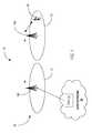
- FIG. 1illustrates an exemplary communication network 10 indicated generally by the numeral 10 that employs self-backhauling relaying.
- Communication network 10comprises a core network 14 and radio access network 16.
- the core network 14includes a serving gateway node (S-GW) 15 provides a connection to a packet data network, such as the Internet.
- S-GW 15routes traffic to and from user terminals 20 operating within the communication network 10.
- the radio access network 16comprises a plurality of base stations 18 providing radio coverage in respective cells 12 of the communication network 10. Two base stations 18 are illustrated in the Figures: a self-backhauled base station or some other type of relaying device, referred to herein as the relay 18a, and a donor base station 18b.
- the relay 18ais wirelessly connected to the core network 14 via the donor base station 18b.
- the radio technology used for the backhauling link between the relay 18a and donor base station 18bis based on the same radio technology used for communications with the user terminals 20, possibly with some additional extensions to optimize for the backhauling application.
- LTE-based, or at least LTE-like, radio linkshould also be used for the self-backhauling link.
- the present inventionprovides a method for identifying the user terminal 20 served by a relay 18a via the donor base station 18b for both uplink and downlink communications.
- a brief review of the protocol stack architectureis given below.
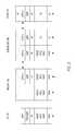
- Fig. 2illustrates one exemplary end-to-end protocol stack architecture where the donor base station 18b hides the relay 18a from the core network 14.
- a user terminal 20 served by the relay 18ais seen from the rest of the network 10 as being served directly via the donor base station 18b.
- a downlink (DL) transmissioncan be followed from right to left in Figure 2 .
- downlink packets for the user terminal 20are first tunneled from the serving gateway (S-GW) 15 in the core network 14 to the donor base station 18b (downlink), as the S-GW 15 believes that the user terminal 20 is connected to the base station 18b.
- S-GWserving gateway
- the most straightforward way for the donor base station 18b to forward the packets to the user terminal 20is to translate the incoming GTP tunnel to an outgoing GTP tunnel toward the relay 18a with a one-to-one mapping, i.e., there is one GTP tunnel per user terminal bearer on the backhaul link as well.
- the base station 18bmaps the packets to a common backhaul radio bearer, i.e., the packets of multiple user terminals 20 are sent on the same radio bearer on the backhaul link. There may be multiple backhaul radio bearers for different QoS classes.
- the relay 18amaps the packets to the corresponding user terminal radio bearers on the link between the relay 18a and user terminal 20 based on the GTP tunnel ID (TEID).
- TEIDGTP tunnel ID
- the protocol architecture shown in Fig. 2provides a basis for understanding the present invention
- the principles describedare applicable to other realizations of the self-backhauling protocol architecture.
- the present inventionis generally applicable to any alternatives where the donor base station 18b can identify the user terminal bearers to which the incoming packets belong. In order to perform this identification, it is not necessarily required that the GTP tunnels originating from the SGW 15 and belonging to individual user terminal bearers are terminated in the donor base station 18b, as it is shown in the Fig. 2 above.
- the base station 18bcould identify the user terminal bearers by sniffing into the bypassed tunnel IDs.
- the user terminal 20is addressed via the PDCCH (Physical Downlink Control Channel) for both for DL and UL transmissions.
- PDCCHPhysical Downlink Control Channel
- the relay 18ainstead of the individual user terminals 20 on the PDCCH. Otherwise, a PDCCH allocation would have to be transmitted separately for each user terminal 20, which is not acceptable because the PDCCH is expected to be a limited resource in an LTE system.
- the base station 18bmaps the packets from multiple user terminals 20 to a common backhaul radio bearer.
- the relay 18amust be able to deliver the received packets to the correct user terminal 20.
- the user terminal and the corresponding radio bearermay be identified based on the GTP tunnel ID.
- the relay 18aupon packet arrival, associate the received packets with the correct user terminal 20.
- One solutionis to determine the user terminal identity from the GTP-u header of the packets received from the S-GW 15.
- a drawback of this approachis that the header must be transmitted on the backhaul link and thus create unnecessary overhead on the radio resource.
- no Robust Header Compression (RoHC) mechanismis applied to the overhead bits. The overhead from the GTP-u header and associated UDP/IP headers will therefore lead to unnecessary waste of scarce radio resources.
- RoHCRobust Header Compression
- the present inventionreduces the overhead for LTE relaying (layer 2 and layer 3), by providing a more efficient mechanism for user terminal and bearer identification as compared to using GTP-u and associated UDP/IP headers.
- the resulting reduction in overheadsaves radio resources on the backhaul link.
- user terminal and bearer identificationis enabled by including a user terminal and bearer identifier in one of the user plane (UP) protocol layers (PDCP, RLC and MAC) on the radio link between the donor base station 18b and relay 18a.
- UP protocol layersthe radio link protocol layers
- the radio link protocol layersare referred to herein as the radio link protocol layers, as these layers are specified by the applicable air interface specification.
- the GTP tunnelis terminated at the donor base station 18b.
- the donor base station 18bremoves the GTP-u and associated UDP/IP headers completely to allow header compression of the end user IP packets directly on the backhaul link.
- the donor base station 18bincludes a user terminal and bearer identifier within one of the radio interface user plane (UP) protocol layers to enable the mapping in the downlink at the relay 18a from the incoming backhaul radio bearer to a user terminal specific radio bearer and in the uplink at the base station 18b from a backhaul radio bearer to a user terminal specific GTP tunnel.
- UPradio interface user plane
- a separate user terminal bearer identification fieldis introduced in the PDCP header. This field indicates which user terminal radio bearer the packet should be transmitted on by the relay 18a for downlink communications and which GTP tunnel the packet should be transmitted on by the base station 18b for uplink communications.
- a second approach for inserting user terminal and bearer identifier into the PDCP layeris to reuse, in the backhaul link, the existing CID (Context Identifier) field in the header compression protocol as the user terminal bearer identification field to indicate which user terminal specific GTP tunnel (uplink) and radio bearer (downlink) a packet received on the backhaul link should be mapped to.
- the CID field in the header compression protocolis normally used to identify application flows.
- the CID fieldis used in the header compression protocol on the backhaul link to identify user terminal radio bearers, which requires that different user terminal radio bearers / GTP tunnels are always assigned different CID values (-65000 values are possible).
- the mapping between user terminal radio bearers / GTP tunnels and CIDscould either be hard coded e.g. RB id 1 uses CID 1-20, or it can be explicitly signaled between the relay 18a and the base station 18b, or it can be configured using operation and maintenance system .
- Possible signaling protocolsinclude S1/X2 and RRC signaling.
- An alternative to hard coding and explicit signalingis to assign the CID ⁇ -> RB/GTP mapping implicitly, e.g. based on the order the bearers are setup or some other scheme. The advantage of this approach is that it does not mandate standardization changes to the PDCP protocol.
- the relay 18amay omit deciphering/decompression when forwarding between the backhaul radio link and the user terminal radio link. Instead, the relay 18a node can simply map and forward the PDCP PDUs between the incoming and the outgoing bearers without any further PDCP processing.
- the user terminal and bearer identifiercan also be inserted into RLC layer signaling.
- a separate user terminal bearer identification fieldis introduced in the RLC header. This field indicates which user terminal radio bearer the packet should be transmitted on by the relay 18a (downlink) or which GTP tunnel the packet should be transmitted on by the base station 18b (uplink).
- This approachassumes that a separate PDCP - machine (i.e. header (de)compression and (de)ciphering machines) and possible RLC machine is used per user terminal bearer (multiplexing below PDCP or RLC). This solution may require standardization changes to the RLC protocol.
- one RLC PDUmay contain upper layer packets concatenated from different user terminal radio bearers. Therefore, the RLC header should have as many user terminal bearer identification fields as the number of upper layer PDUs concatenated from different user terminals 20 in the RLC PDU. In order to keep header size small, it should be possible to set dynamically the size of the user terminal bearer identification field in each RLC PDU depending on the particular upper layer PDUs concatenated.
- the user terminal specific bearer identifiercan also be inserted into MAC layer signaling.
- a separate user terminal radio bearer identification fieldis introduced in the MAC header.
- Introducing the new field in the MAC headercan be solved by extending the existing logical channel identifier field (LCID) in the MAC header with a UE specific terminal identifier.
- This fieldindicates which user terminal radio bearer the packet should be transmitted on by the relay 18a (downlink) and which GTP tunnel the packet should be transmitted on by the base station 18b (uplink).
- This solutionassumes that a separate PDCP - machine (i.e. header (de)compression and (de)ciphering machines) and RLC machine be run per user terminal bearer (multiplexing is performed on MAC layers).
- This approachmay require standardization changes to the MAC protocol.
- one MAC PDUmay contain upper layer packets multiplexed from different user terminal radio bearers. Therefore, the MAC header would need to hold as many user terminal bearer identification fields as the number of upper layer PDUs multiplexed from different user terminals 20 into the given MAC PDU. In order to save header space, it should be possible to set dynamically the size of the user terminal bearer identification field in each MAC PDU depending on the particular upper layer PDUs multiplexed.
- user terminal and bearer identificationis enabled by introducing an additional UP protocol layer above the PDCP layer that replaces the GTP and associated UDP/IP headers with a specific bearer identification field in order to reduce the overhead associated with these headers.
- Header compressionmay be performed in the new UP protocol layer.
- header compressionmay be performed by the PDCP layer of the backhaul link assuming the bearer identification field can be passed transparently through the header compression.
- Header compression in the new UP protocol layeravoids the need to perform header compression in the PDCP layer of the backhaul link. Consequently, the bearer identity field can be transferred as a part of the header compression header.
- This approachis similar to the first embodiment using the PDCP layer to transmit user terminal and bearer identification. The difference is that the existing PDCP layer of the backhaul link does not need to be modified in this approach.
- the PDCP layershould ignore the bearer identification field added by the higher layer.
- One approach to this problemis to explicitly configure the PDCP layer to ignore the first of last N bytes, which carry the user terminal and bearer identification.
- the user terminal and bearer identificationcan be attached as a trailer (at the end) of the IP packets.
- the traileris ignored by the header compression algorithm, which is more interested in the beginning of the packet. This assumes that the header compression algorithm does not rely on the IP packet length.
- the header compression algorithmrelies on IP packet length, it may be required that the upper layer modifies the IP length field (e.g. by adding a fixed number of bytes) and other fields such as IP checksum, TCP/UDP length fields etc.
- all multiplexing of different user terminal bearersis performed above PDCP meaning that the PDCP entity is per backhaul bearer (not per user terminal bearer).
- a header compression layerwithin the GTP tunnel which will compress the end user IP packets. More particularly, a header compression PDCP layer (HC-PDCP) is introduced for compressing the GTP-u header.
- HC-PDCPheader compression PDCP layer
- the additional header compression layerdoes not necessarily mean new protocol headers, such as, PDCP headers. In the typical embodiment, this would be realized by running plain IP header compressors (e.g., RoHC) on the two ends of the link, which replace fields of the IP header (or parts of it) with their compressed form.
- the GTP-u and associated UDP/IP headerscan be kept since the HC- PDCP entities on the backhaul link will compress the GTP/UDP/IP headers.
- the relay 18acan rely on the GTP-u header to determine the mapping between GTP tunnels and user terminal radio bearers. Possible protocols to configure the header compression within the GTP tunnel could be GTP-c or RRC signaling or S1 signaling.
- Another potential alternative for this embodimentis to omit the additional header compression layer (HC-PDCP) in the GTP tunnel and extend the header compression profiles of the backhaul link PDCP protocol such that it can handle the compression of the GTP/UDP/IP tunnel headers and the end user IP protocol headers together.
- RoHCRobot Header Compression
- network 10 nodes illustrated in Figs. 2- 5may comprise specially programmed computer systems programmed to operate as hereinabove described.
- the computer systemsmay comprise one or more processors, microcontrollers, hardware, of a combination thereof along with memory for storing programming instructions and data needed for operation as described above.
- Figs. 6 and 7illustrate the operation of a donor base station 18b in one exemplary embodiment of the invention.
- identifying informationis inserted into radio link protocol packets transmitted over the multiplexed backhaul link between the donor base station 18b and relay 18a.
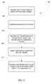
- Fig. 6illustrates an exemplary procedure 100 implemented by the donor base station 18b for forwarding downlink packets intended for a user terminal 20.
- the procedure 100begins when the donor base station 18b receives a data packet from the serving gateway 15 over a user specific tunnel for delivery to the user terminal 20 (block 102).
- the donor base station 18bmaps the tunnel identifier for the user specific tunnel to a user specific identifier used on the link between the relay 18a and donor base station 18b (block 104), and forwards the data packet to the relay 18a over a multiplexed backhaul link in one or more radio link protocol packets (block 106).
- the base station 18binserts the user-specific identifier into at least one of the radio link protocol packets to enable the relay 18a to identify the user terminal 20 for which the data packet is intended (block 108).
- the user specific identifiermay comprise a user specific radio bearer identifier that identifies a specific radio bearer assigned to the user terminal.
- the user specific radio bearer identifiermay be inserted into the PDCP header, RLC header, or MAC header of the radio link protocol packets.
- the relay 18athen forwards the packet to the user terminal 20 over the indicated user specific radio bearer.
- Fig. 7illustrates an exemplary procedure 150 implemented by the donor base station 18b for forwarding uplink packets received from the relay 18a to the serving gateway 15.
- the procedure 150begins when the donor base station 18b receives a data packet from the relay 18a over a multiplexed backhaul link in one or more radio link protocol packets (block 152). Before transmitting the data packet, the relay 18a inserts a user specific identifier into at least one of the radio link protocol packets.
- the donor base station 18bdetermines the user terminals sending the data packet from a user specific identifier inserted into the header of at least one of the radio link protocol packets (block 154).
- the donor base station 18bdetermines a tunnel identifier for a user specific tunnel between the donor base station 18b and gateway 15 based on the user specific identifier (block 156) and forwards the data packet to the gateway 15 over the user specific tunnel for the identified user terminal (block 158).
- Figs. 8 and 9illustrate the operation of a relay 18a in one exemplary embodiment of the invention.
- identifying informationis inserted into radio link protocol packets transmitted over the multiplexed backhaul link between the donor base station 18b and relay 18a.
- Fig. 8illustrates an exemplary procedure 200 for forwarding downlink packets received from a donor base station 18b to a user terminal 20.
- the procedure 200begins when the relay 18a receives a data packet from a user terminal 20 (block 202).
- the relay 18aforwards the data packet to the donor base station 18b over a multiplexed backhaul link in one or more radio link protocol packets (block 204).
- the relay 18ainserts the user-specific identifier into at least one of the radio link protocol packets to enable the donor base station 18b to identify the user terminal for which the data packet is intended (block 206).
- the user specific identifiermay comprise a user specific radio bearer identifier that identifies a specific radio bearer assigned to the user terminal.
- the user specific radio bearer identifiermay be inserted into the PDCP header, RLC header, or MAC header of the radio link protocol packets.
- Fig. 9illustrates an exemplary procedure 250 implemented by the relay 18a for forwarding down link packets received from the donor base station 18b to the user terminal 20.
- the procedure 250begins when the relay 18a receives a data packet from the donor base station 18b over a multiplexed backhaul link in one or more radio link protocol packets (block 252). Before transmitting the data packet, the relay 18a inserts a user specific identifier into at least one of the radio link protocol packets.
- the donor relay 18adetermines the user terminal to receive the data packet from a user specific identifier inserted into the header of at least one of the radio link protocol packets (block 254) and forwards the data packet to the identified user terminal (block 256).
- Figs. 10 and 11illustrate the operation of a donor base station 18b in an alternate embodiment of the invention.
- the tunneling header of the data packets transmitted over a user specific tunnel from the serving gateway 15are compressed for transmission over the backhaul link between the donor base station 18b and relay 18a.
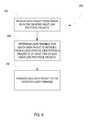
- Fig. 10illustrates an exemplary procedure 300 implemented by the donor base station 18b for forwarding packets received from the serving gateway 15 to the relay 18a.
- the procedure 300begins when the donor base station 18b receives a packet over a GTP tunnel from the serving gateway 15 (block 302).
- the donor base station 18bdecapsulates the data packet and compresses the header (block 304).
- the donor base stationdetermines the user terminal for which the data packet is intended from the tunnel ID of the GTP-u header received from the gateway 15 and maps the data packet received over the incoming tunnel from the serving gateway 15 to an outgoing tunnel toward the relay 18a (block 306).
- the donor base station 18bencapsulates the compressed data packet in a tunneling packet and forwards the data packet to the relay 18a (block 308).
- the outgoing tunnelis a user specific tunnel in a multiplexed backhaul link between the donor base station 18b and relay18a.
- the donor base station 18bPrior to transmission to the relay 18a, the donor base station 18b inserts a user-specific identifier into the tunneling header to enable the relay to identify the user terminal 20 (block 310).
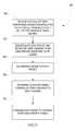
- Fig. 11illustrates an exemplary procedure 350 implemented by the donor base station 18b for forwarding uplink packets received from the relay 18a over the backhaul link to the serving gateway 15.
- the procedure 350begins when the donor base station 18a receives a data packet from the relay 18a over the backhaul radio bearer (block 352).
- a tunneling protocolsuch as GTP
- the donor base station 18bdecapsulates the compressed data packet (block 354) and decompresses the header of the data packet (block 356).
- the donor base station 18bdetermines the outgoing tunnel toward the serving gateway 15 (block 358), and forwards the data packet over a user specific tunnel between the donor base station 18b and serving gateway 15 (block 360).
- the donor base stationmay determine the outgoing tunnel from a user-specific identifier contained in the GTP-u header received from the relay 18a.
- Fig. 12illustrates an exemplary procedure implemented by a relay 18a in a multi-hop communication system for compressing and forwarding uplink packets to a donor base station 18bfor transmission to a serving gateway.
- the procedurebegins when the relay 18a receives a data packet over the air interface from a user terminal 20 (block 402).
- the relay 18acompresses the header of the data packet (block 404) and encapsulates the data packet in a GTP packet for transmission to the donor base station 18b (block 406).
- the relay 18ainserts a user-specific identifier into the GTP header (block 408) and forwards the encapsulated and compressed data packet to the donor base station 18b (block 410).
- Fig. 13illustrates an exemplary procedure 450 implemented by a relay 18a in a multi-hop communication system for decompressing and forwarding downlink packets received from a donor base station to a user terminal.
- the relay 18areceives a data packet from the donor base station over encapsulated in a GTP packet (block 452).
- the relay 18adecapsulates the data packet and decompresses the header of the data packet (block 454).
- the donor base station 18bdetermines the user terminal 20 sending the data packet from the GTP header (block 456), and the corresponding tunnel towards the gateway 15 (block 458).
- the donor base station 18bthen forwards the decompressed data packet to the identified user terminal 20 over the air interface (block 460).
- Fig. 14illustrates an exemplary base station 18b and relay 18a in a multi-hop communication system.
- the base station 18bcomprises a network interface 22 for communicating with the serving gateway 15, a radio transceiver 24 for communicating over a wireless backhaul link with the relay 18a, and a processing circuit 26 for implementing the packet forwarding protocols as herein described.
- the network interface 22may, for example, comprise an Ethernet interface.
- the radio transceiver 24may be configured to implement known wireless communication protocols, such as LTE, WCDMA, and WiMAX, without modifications for the backhaul link.
- the processing circuit 26comprises one or more processors, hardware, or a combination thereof, and memory for implementing the forwarding procedures as shown in Figs. 6-7 and 10-11 .
- the relay 18aalso includes a radio transceiver 28 and a processing circuit 30.
- the transceiveris used both for communications with the donor base station 18b and the user terminal.
- the processing circuit 30comprises one or more processors, hardware, or a combination thereof, and memory for implementing the forwarding procedures as shown in Figs. 7 - 8 , and 12-13 .
- LTE Release 10is likely to include a self backhauling solution, in which case a low overhead on the backhaul link is desirable.
- the exemplary embodiments of the inventionreduce the protocol overhead when applied to a self backhauling or relaying solution in a LTE system. This implies a more efficient utilization of the radio resource and hence improved system performance.
- the magnitude of the gain realized by reducing overheadis related to the packet size. When transmitting very large packets, some additional bits do not affect so much. However, for services like VolP with smaller IP packets, the gain is significant.
Landscapes
- Engineering & Computer Science (AREA)
- Computer Networks & Wireless Communication (AREA)
- Signal Processing (AREA)
- Mobile Radio Communication Systems (AREA)
- Radio Relay Systems (AREA)
Description
- The adoption of multi-hop communication has been proposed for Long Term Evolution (LTE) systems to improve the coverage and capacity of LTE networks. In multi-hop cellular systems, communications between the base station and a user terminal (UT) can take multiple hops with the help of additional intermediate nodes. There are different types of intermediate nodes. Repeaters operate at Layer 1 by amplifying the received signal. Relays decode the received transport block before forwarding and request HARQ retransmissions if necessary, thus operating at Layer 2. Self-backhauling is a Layer 3 relaying technique to improve the coverage and data rates of the LTE network. The terms "relay" and "relaying" are used herein to refer to both layer 2 and layer 3 relaying unless otherwise noted.
- When relaying is employed, the packets from multiple user terminals are mapped to a common backhaul radio bearer that carries traffic for many user terminals between the base station (eNB) and relay. To enable users to be multiplexed on the backhaul link between base station and relay, it is necessary that the relay, upon packet arrival, deliver the received packets to the correct user in the downlink direction. When tunneling is employed between the base station and the relay, the user bearer is identified from the GTP-u header of the packet. A drawback of this approach is that the header must be transmitted on the backhaul link creating unnecessary overhead on the radio resource. Further, existing header compression mechanisms, such as Robust Header Compression (RoHC) mechanism cannot be applied to reduce the overhead due to GTP tunneling. The overhead from the GTP-u header and associated UDP/IP headers will lead to unnecessary waste of scarce radio resources.
- FromCATT: "Discussion on user plane protocol stack of type 1 relay" 3GPP DRAFT; R2-092344, 3RD GENERATION PARTNERSHIP PROJECT (3GPP), MOBILE COMPETENCE CENTRE ; 650, ROUTE DES LUCIOLES ; F-06921 SOPHIA-ANTIPOLIS CEDEX ; FRANCE, no. Seoul, Korea; 20090319, 19 March 2009 (2009-03-19), XP050340088 a user plane protocol stack is known, wherein a tunnel protocol is introduced between RN and eNb. IP packets are de-capsulated by the parent eNb from GTP packets and sent to corresponding tunnels via the RN to the OE.
- FromHuawei: "R2-092179 Consideration for Relay" 3GPP TSG RAN WG2 Meeting 65bis 17 March 2009 (2009-03-17), pages 1-5, XP002594702 Retrieved from the Internet: URL:http://ftp.3gpp.org/tsg_ran/WG2_RL2/TSGR2_65bis/Docs/ [retrieved on 2010-07-30] it is known to multiplex packets for a plurality of user terminals over a single radio bearer on a backhaul between a donor base station and a relay in a multi-hop communication system, wherein wGTP-u tunnel is maintained up to the relay node.
- The present invention relates to two methods as defined in claims 1 and 2, a donor base station according to claim 3 and a relay according to claim 4 that reduce the overhead for LTE relaying (layer 2 and layer 3), which will save radio resources on the backhaul link. Reduction in overhead is achieved by providing a more efficient mechanism for user terminal and bearer identification as compared to using GTP-u and associated UDP/IP headers.
- In one of the embodiments, not claimed in the present invention, user terminal and bearer identification is enabled by signaling a user terminal and radio bearer identifier in the UP protocol layers (PDCP, RLC and MAC) of the radio link. In this embodiment it is possible to remove the GTP-u and associated UDP/IP headers completely and allow header compression of the end user IP packets directly on the backhaul link.
- In a second embodiment, claimed in the present invention, user terminal and bearer identification is enabled by introducing an additional UP protocol layer in the radio link above the Packet Data Convergence Protocol (PDCP) layer that replaces the unnecessary GTP and associated UDP/IP headers with a specific bearer identity field in order to reduce the overhead associated with these headers. This protocol layer also compresses the headers of the end user packets.
- In a third embodiment not claimed in the present invention, user terminal and bearer identification is enabled by introducing a header compression layer within the GTP tunnel which will compress the end user IP packets. In this embodiment, the GTP-u and associated UDP/IP headers can be used and the overall protocol overhead would still be low, especially if header compression of the UDP/IP layers is used on the backhaul link.
Fig. 1 illustrates an exemplary multi-hop communication system.Fig. 2 illustrates an exemplary protocol architecture for a multi-hop communication system.Fig. 3 illustrates an exemplary protocol architecture for a multi-hop communication system wherein user-specific bearer information is contained in a radio link protocol layer such as the PDCP, RLC, or MAC layer.Fig. 4 illustrates an exemplary protocol architecture for a multi-hop communication system wherein user-specific bearer information is contained in a protocol layer above the PDCP layer.Fig. 5 illustrates an exemplary protocol architecture for a multi-hop communication system wherein user-specific bearer information is contained in a header compression layer in the GTP tunnel between the donor base station and the relay.Fig. 6 illustrates an exemplary procedure implemented by a donor base station in a multi-hop communication system for inserting bearer identification information into downlink packets and forwarding downlink packets to a relay for transmission to a user terminal by the relay.Fig. 7 illustrates an exemplary procedure implemented by a donor base station in a multi-hop communication system for mapping and forwarding uplink packets received from a relay to a serving gateway in the core network.Fig. 8 illustrates an exemplary procedure implemented by a relay in a multi-hop communication system for inserting bearer identification information into uplink packets and forwarding uplink packets to a donor base station for transmission to a serving gateway in a core network.Fig. 9 illustrates an exemplary procedure implemented by a relay in a multi-hop communication system for forwarding downlink packets received from a donor base station to a user terminal.Fig. 10 illustrates an exemplary procedure implemented by a donor base station in a multi-hop communication system for compressing and forwarding downlink packets to a relay for transmission to a user terminal by the relay.Fig. 11 illustrates an exemplary procedure implemented by a donor base station in a multi-hop communication system for decompressing and forwarding uplink packets received from a relay to a serving gateway in the core network.Fig. 12 illustrates an exemplary procedure implemented by a relay in a multi-hop communication system for compressing and forwarding uplink packets to a donor base station for transmission to a serving gateway.Fig. 13 illustrates an exemplary procedure implemented by a relay in a multi-hop communication system for decompressing and forwarding downlink packets received from a donor base station to a user terminal.Fig. 14 illustrates an exemplary donor base station and relay for a multi-hop communication system.Figure 1 illustrates anexemplary communication network 10 indicated generally by thenumeral 10 that employs self-backhauling relaying.Communication network 10 comprises acore network 14 andradio access network 16. Thecore network 14 includes a serving gateway node (S-GW) 15 provides a connection to a packet data network, such as the Internet. The S-GW 15 routes traffic to and fromuser terminals 20 operating within thecommunication network 10. Theradio access network 16 comprises a plurality of base stations 18 providing radio coverage inrespective cells 12 of thecommunication network 10. Two base stations 18 are illustrated in the Figures: a self-backhauled base station or some other type of relaying device, referred to herein as therelay 18a, and adonor base station 18b. Therelay 18a is wirelessly connected to thecore network 14 via thedonor base station 18b. The radio technology used for the backhauling link between therelay 18a anddonor base station 18b is based on the same radio technology used for communications with theuser terminals 20, possibly with some additional extensions to optimize for the backhauling application. As an example, when thedonor base station 18b and therelay 18a use LTE radio access for communication withuser terminals 20 within the cell, LTE-based, or at least LTE-like, radio link should also be used for the self-backhauling link.- The present invention provides a method for identifying the
user terminal 20 served by arelay 18a via thedonor base station 18b for both uplink and downlink communications. To understand the present invention, a brief review of the protocol stack architecture is given below.Fig. 2 illustrates one exemplary end-to-end protocol stack architecture where thedonor base station 18b hides therelay 18a from thecore network 14. Thus, auser terminal 20 served by therelay 18a is seen from the rest of thenetwork 10 as being served directly via thedonor base station 18b. A downlink (DL) transmission can be followed from right to left inFigure 2 . It can be seen that downlink packets for theuser terminal 20 are first tunneled from the serving gateway (S-GW) 15 in thecore network 14 to thedonor base station 18b (downlink), as the S-GW 15 believes that theuser terminal 20 is connected to thebase station 18b. There is one GTP tunnel per user terminal bearer. - The most straightforward way for the
donor base station 18b to forward the packets to theuser terminal 20 is to translate the incoming GTP tunnel to an outgoing GTP tunnel toward therelay 18a with a one-to-one mapping, i.e., there is one GTP tunnel per user terminal bearer on the backhaul link as well. Thebase station 18b maps the packets to a common backhaul radio bearer, i.e., the packets ofmultiple user terminals 20 are sent on the same radio bearer on the backhaul link. There may be multiple backhaul radio bearers for different QoS classes. After the packets arrive at therelay 18a, therelay 18a maps the packets to the corresponding user terminal radio bearers on the link between therelay 18a anduser terminal 20 based on the GTP tunnel ID (TEID). - While the protocol architecture shown in
Fig. 2 provides a basis for understanding the present invention, those skilled in the art will appreciate that the principles described are applicable to other realizations of the self-backhauling protocol architecture. The present invention is generally applicable to any alternatives where thedonor base station 18b can identify the user terminal bearers to which the incoming packets belong. In order to perform this identification, it is not necessarily required that the GTP tunnels originating from theSGW 15 and belonging to individual user terminal bearers are terminated in thedonor base station 18b, as it is shown in theFig. 2 above. For example, in protocol realizations where the tunnel goes transparently via thedonor base station 18b, thebase station 18b could identify the user terminal bearers by sniffing into the bypassed tunnel IDs. - During normal data transmission from a
base station 18b to auser terminal 20, theuser terminal 20 is addressed via the PDCCH (Physical Downlink Control Channel) for both for DL and UL transmissions. When data is sent betweendonor base station 18b andrelay 18a, it is beneficial to address therelay 18a instead of theindividual user terminals 20 on the PDCCH. Otherwise, a PDCCH allocation would have to be transmitted separately for eachuser terminal 20, which is not acceptable because the PDCCH is expected to be a limited resource in an LTE system. - For the forwarding solution shown in
Fig. 2 , thebase station 18b maps the packets frommultiple user terminals 20 to a common backhaul radio bearer. Therelay 18a must be able to deliver the received packets to thecorrect user terminal 20. The user terminal and the corresponding radio bearer may be identified based on the GTP tunnel ID. To enableuser terminals 20 to be multiplexed on the backhaul link betweenbase station 18b andrelay 18a, it is necessary that therelay 18a, upon packet arrival, associate the received packets with thecorrect user terminal 20. One solution is to determine the user terminal identity from the GTP-u header of the packets received from the S-GW 15. A drawback of this approach is that the header must be transmitted on the backhaul link and thus create unnecessary overhead on the radio resource. Further, no Robust Header Compression (RoHC) mechanism is applied to the overhead bits. The overhead from the GTP-u header and associated UDP/IP headers will therefore lead to unnecessary waste of scarce radio resources. - The present invention reduces the overhead for LTE relaying (layer 2 and layer 3), by providing a more efficient mechanism for user terminal and bearer identification as compared to using GTP-u and associated UDP/IP headers. The resulting reduction in overhead saves radio resources on the backhaul link.
- In a first embodiment illustrated in
Fig. 3 , user terminal and bearer identification is enabled by including a user terminal and bearer identifier in one of the user plane (UP) protocol layers (PDCP, RLC and MAC) on the radio link between thedonor base station 18b andrelay 18a. For convenience, the UP protocol layers on the radio link are referred to herein as the radio link protocol layers, as these layers are specified by the applicable air interface specification. In the first embodiment, the GTP tunnel is terminated at thedonor base station 18b. Thedonor base station 18b removes the GTP-u and associated UDP/IP headers completely to allow header compression of the end user IP packets directly on the backhaul link. Thedonor base station 18b includes a user terminal and bearer identifier within one of the radio interface user plane (UP) protocol layers to enable the mapping in the downlink at therelay 18a from the incoming backhaul radio bearer to a user terminal specific radio bearer and in the uplink at thebase station 18b from a backhaul radio bearer to a user terminal specific GTP tunnel. - Two different approaches can be used to insert a user terminal and bearer identifier in the PDCP layer. In a first approach, a separate user terminal bearer identification field is introduced in the PDCP header. This field indicates which user terminal radio bearer the packet should be transmitted on by the
relay 18a for downlink communications and which GTP tunnel the packet should be transmitted on by thebase station 18b for uplink communications. In this approach, it is possible to either run a separate PDCP - machine (i.e. header (de)compression and (de)ciphering machines) per user terminal bearer (multiplexing below PDCP), or alternatively, run one PDCP machine per backhaul bearer (multiplexing above PDCP). This approach may require standardization changes to the PDCP protocol. - A second approach for inserting user terminal and bearer identifier into the PDCP layer is to reuse, in the backhaul link, the existing CID (Context Identifier) field in the header compression protocol as the user terminal bearer identification field to indicate which user terminal specific GTP tunnel (uplink) and radio bearer (downlink) a packet received on the backhaul link should be mapped to. The CID field in the header compression protocol is normally used to identify application flows. In this approach, the CID field is used in the header compression protocol on the backhaul link to identify user terminal radio bearers, which requires that different user terminal radio bearers / GTP tunnels are always assigned different CID values (-65000 values are possible). The mapping between user terminal radio bearers / GTP tunnels and CIDs could either be hard coded e.g. RB id 1 uses CID 1-20, or it can be explicitly signaled between the
relay 18a and thebase station 18b, or it can be configured using operation and maintenance system . Possible signaling protocols include S1/X2 and RRC signaling. An alternative to hard coding and explicit signaling is to assign the CID <-> RB/GTP mapping implicitly, e.g. based on the order the bearers are setup or some other scheme. The advantage of this approach is that it does not mandate standardization changes to the PDCP protocol. - In case there is one PDCP machine per user terminal bearer in the
donor base station 18b (i.e., multiplexing is done below PDCP), meaning that the ciphering and the header compression are performed independently for each user terminal bearer at thedonor base station 18b, therelay 18a may omit deciphering/decompression when forwarding between the backhaul radio link and the user terminal radio link. Instead, therelay 18a node can simply map and forward the PDCP PDUs between the incoming and the outgoing bearers without any further PDCP processing. - As previously noted, the user terminal and bearer identifier can also be inserted into RLC layer signaling. With this approach, a separate user terminal bearer identification field is introduced in the RLC header. This field indicates which user terminal radio bearer the packet should be transmitted on by the
relay 18a (downlink) or which GTP tunnel the packet should be transmitted on by thebase station 18b (uplink). This approach assumes that a separate PDCP - machine (i.e. header (de)compression and (de)ciphering machines) and possible RLC machine is used per user terminal bearer (multiplexing below PDCP or RLC). This solution may require standardization changes to the RLC protocol. - It should be noted that one RLC PDU may contain upper layer packets concatenated from different user terminal radio bearers. Therefore, the RLC header should have as many user terminal bearer identification fields as the number of upper layer PDUs concatenated from
different user terminals 20 in the RLC PDU. In order to keep header size small, it should be possible to set dynamically the size of the user terminal bearer identification field in each RLC PDU depending on the particular upper layer PDUs concatenated. - The user terminal specific bearer identifier can also be inserted into MAC layer signaling. In this approach, a separate user terminal radio bearer identification field is introduced in the MAC header.. Introducing the new field in the MAC header can be solved by extending the existing logical channel identifier field (LCID) in the MAC header with a UE specific terminal identifier. This field indicates which user terminal radio bearer the packet should be transmitted on by the
relay 18a (downlink) and which GTP tunnel the packet should be transmitted on by thebase station 18b (uplink). This solution assumes that a separate PDCP - machine (i.e. header (de)compression and (de)ciphering machines) and RLC machine be run per user terminal bearer (multiplexing is performed on MAC layers). This approach may require standardization changes to the MAC protocol. - It should be noted that one MAC PDU may contain upper layer packets multiplexed from different user terminal radio bearers. Therefore, the MAC header would need to hold as many user terminal bearer identification fields as the number of upper layer PDUs multiplexed from
different user terminals 20 into the given MAC PDU. In order to save header space, it should be possible to set dynamically the size of the user terminal bearer identification field in each MAC PDU depending on the particular upper layer PDUs multiplexed. - In a second embodiment of the present invention illustrated in
Fig. 4 , user terminal and bearer identification is enabled by introducing an additional UP protocol layer above the PDCP layer that replaces the GTP and associated UDP/IP headers with a specific bearer identification field in order to reduce the overhead associated with these headers. In order to further reduce the overhead, it is useful to allow header compression of the end user packets. Header compression may be performed in the new UP protocol layer. Alternatively, header compression may be performed by the PDCP layer of the backhaul link assuming the bearer identification field can be passed transparently through the header compression. - Header compression in the new UP protocol layer avoids the need to perform header compression in the PDCP layer of the backhaul link. Consequently, the bearer identity field can be transferred as a part of the header compression header. This approach is similar to the first embodiment using the PDCP layer to transmit user terminal and bearer identification. The difference is that the existing PDCP layer of the backhaul link does not need to be modified in this approach.
- If header compression is performed in the PDCP layer, the PDCP layer should ignore the bearer identification field added by the higher layer. One approach to this problem is to explicitly configure the PDCP layer to ignore the first of last N bytes, which carry the user terminal and bearer identification. Alternatively, the user terminal and bearer identification can be attached as a trailer (at the end) of the IP packets. In general, the trailer is ignored by the header compression algorithm, which is more interested in the beginning of the packet. This assumes that the header compression algorithm does not rely on the IP packet length. In case the header compression algorithm relies on IP packet length, it may be required that the upper layer modifies the IP length field (e.g. by adding a fixed number of bytes) and other fields such as IP checksum, TCP/UDP length fields etc.
- In the second embodiment, all multiplexing of different user terminal bearers is performed above PDCP meaning that the PDCP entity is per backhaul bearer (not per user terminal bearer).
- In a third embodiment illustrated in
Fig. 5 , user terminal and bearer identification is enabled by introducing a header compression layer within the GTP tunnel which will compress the end user IP packets. More particularly, a header compression PDCP layer (HC-PDCP) is introduced for compressing the GTP-u header. It is noted that the additional header compression layer does not necessarily mean new protocol headers, such as, PDCP headers. In the typical embodiment, this would be realized by running plain IP header compressors (e.g., RoHC) on the two ends of the link, which replace fields of the IP header (or parts of it) with their compressed form. In this embodiment, the GTP-u and associated UDP/IP headers can be kept since the HC- PDCP entities on the backhaul link will compress the GTP/UDP/IP headers. Therelay 18a can rely on the GTP-u header to determine the mapping between GTP tunnels and user terminal radio bearers. Possible protocols to configure the header compression within the GTP tunnel could be GTP-c or RRC signaling or S1 signaling. - Another potential alternative for this embodiment is to omit the additional header compression layer (HC-PDCP) in the GTP tunnel and extend the header compression profiles of the backhaul link PDCP protocol such that it can handle the compression of the GTP/UDP/IP tunnel headers and the end user IP protocol headers together. This would require new compression profiles for the RoHC (Robust Header Compression) header compression algorithm, which can handle the GTP and the (end user) TCP/UDP headers as extension headers during the compression.
- Those skilled in the art will appreciate that the
network 10 nodes illustrated inFigs. 2- 5 may comprise specially programmed computer systems programmed to operate as hereinabove described. The computer systems may comprise one or more processors, microcontrollers, hardware, of a combination thereof along with memory for storing programming instructions and data needed for operation as described above. Figs. 6 and7 illustrate the operation of adonor base station 18b in one exemplary embodiment of the invention. In this embodiment, identifying information is inserted into radio link protocol packets transmitted over the multiplexed backhaul link between thedonor base station 18b andrelay 18a.Fig. 6 illustrates anexemplary procedure 100 implemented by thedonor base station 18b for forwarding downlink packets intended for auser terminal 20. Theprocedure 100 begins when thedonor base station 18b receives a data packet from the servinggateway 15 over a user specific tunnel for delivery to the user terminal 20 (block 102). Thedonor base station 18b maps the tunnel identifier for the user specific tunnel to a user specific identifier used on the link between therelay 18a anddonor base station 18b (block 104), and forwards the data packet to therelay 18a over a multiplexed backhaul link in one or more radio link protocol packets (block 106). Thebase station 18b inserts the user-specific identifier into at least one of the radio link protocol packets to enable therelay 18a to identify theuser terminal 20 for which the data packet is intended (block 108). As previously noted, the user specific identifier may comprise a user specific radio bearer identifier that identifies a specific radio bearer assigned to the user terminal. The user specific radio bearer identifier may be inserted into the PDCP header, RLC header, or MAC header of the radio link protocol packets. Therelay 18a then forwards the packet to theuser terminal 20 over the indicated user specific radio bearer.Fig. 7 illustrates anexemplary procedure 150 implemented by thedonor base station 18b for forwarding uplink packets received from therelay 18a to the servinggateway 15. Theprocedure 150 begins when thedonor base station 18b receives a data packet from therelay 18a over a multiplexed backhaul link in one or more radio link protocol packets (block 152). Before transmitting the data packet, therelay 18a inserts a user specific identifier into at least one of the radio link protocol packets. Thedonor base station 18b determines the user terminals sending the data packet from a user specific identifier inserted into the header of at least one of the radio link protocol packets (block 154). Thedonor base station 18b determines a tunnel identifier for a user specific tunnel between thedonor base station 18b andgateway 15 based on the user specific identifier (block 156) and forwards the data packet to thegateway 15 over the user specific tunnel for the identified user terminal (block 158).Figs. 8 and9 illustrate the operation of arelay 18a in one exemplary embodiment of the invention. In this embodiment, identifying information is inserted into radio link protocol packets transmitted over the multiplexed backhaul link between thedonor base station 18b andrelay 18a.Fig. 8 illustrates anexemplary procedure 200 for forwarding downlink packets received from adonor base station 18b to auser terminal 20. Theprocedure 200 begins when therelay 18a receives a data packet from a user terminal 20 (block 202). Therelay 18a forwards the data packet to thedonor base station 18b over a multiplexed backhaul link in one or more radio link protocol packets (block 204). Therelay 18a inserts the user-specific identifier into at least one of the radio link protocol packets to enable thedonor base station 18b to identify the user terminal for which the data packet is intended (block 206). As previously noted, the user specific identifier may comprise a user specific radio bearer identifier that identifies a specific radio bearer assigned to the user terminal. The user specific radio bearer identifier may be inserted into the PDCP header, RLC header, or MAC header of the radio link protocol packets.- The
donor base station 18b then forwards the packet to the servinggateway 15.Fig. 9 illustrates anexemplary procedure 250 implemented by therelay 18a for forwarding down link packets received from thedonor base station 18b to theuser terminal 20. Theprocedure 250 begins when therelay 18a receives a data packet from thedonor base station 18b over a multiplexed backhaul link in one or more radio link protocol packets (block 252). Before transmitting the data packet, therelay 18a inserts a user specific identifier into at least one of the radio link protocol packets. Thedonor relay 18a determines the user terminal to receive the data packet from a user specific identifier inserted into the header of at least one of the radio link protocol packets (block 254) and forwards the data packet to the identified user terminal (block 256). Figs. 10 and11 illustrate the operation of adonor base station 18b in an alternate embodiment of the invention. In this embodiment, the tunneling header of the data packets transmitted over a user specific tunnel from the servinggateway 15 are compressed for transmission over the backhaul link between thedonor base station 18b andrelay 18a.Fig. 10 illustrates anexemplary procedure 300 implemented by thedonor base station 18b for forwarding packets received from the servinggateway 15 to therelay 18a. Theprocedure 300 begins when thedonor base station 18b receives a packet over a GTP tunnel from the serving gateway 15 (block 302). Thedonor base station 18b decapsulates the data packet and compresses the header (block 304). The donor base station determines the user terminal for which the data packet is intended from the tunnel ID of the GTP-u header received from thegateway 15 and maps the data packet received over the incoming tunnel from the servinggateway 15 to an outgoing tunnel toward therelay 18a (block 306). Thedonor base station 18b encapsulates the compressed data packet in a tunneling packet and forwards the data packet to therelay 18a (block 308). The outgoing tunnel is a user specific tunnel in a multiplexed backhaul link between thedonor base station 18b and relay18a. Prior to transmission to therelay 18a, thedonor base station 18b inserts a user-specific identifier into the tunneling header to enable the relay to identify the user terminal 20 (block 310).Fig. 11 illustrates anexemplary procedure 350 implemented by thedonor base station 18b for forwarding uplink packets received from therelay 18a over the backhaul link to the servinggateway 15. Theprocedure 350 begins when thedonor base station 18a receives a data packet from therelay 18a over the backhaul radio bearer (block 352). In this embodiment, it is presumed that a tunneling protocol, such as GTP, is used for the transmission of data packets over the backhaul link and that the header of the data packet is compressed by therelay 18a prior to transmission. After receiving the data packet, thedonor base station 18b decapsulates the compressed data packet (block 354) and decompresses the header of the data packet (block 356). Thedonor base station 18b determines the outgoing tunnel toward the serving gateway 15 (block 358), and forwards the data packet over a user specific tunnel between thedonor base station 18b and serving gateway 15 (block 360). The donor base station may determine the outgoing tunnel from a user-specific identifier contained in the GTP-u header received from therelay 18a.Fig. 12 illustrates an exemplary procedure implemented by arelay 18a in a multi-hop communication system for compressing and forwarding uplink packets to a donor base station 18bfor transmission to a serving gateway. The procedure begins when therelay 18a receives a data packet over the air interface from a user terminal 20 (block 402). Therelay 18a compresses the header of the data packet (block 404) and encapsulates the data packet in a GTP packet for transmission to thedonor base station 18b (block 406). Therelay 18a inserts a user-specific identifier into the GTP header (block 408) and forwards the encapsulated and compressed data packet to thedonor base station 18b (block 410).Fig. 13 illustrates anexemplary procedure 450 implemented by arelay 18a in a multi-hop communication system for decompressing and forwarding downlink packets received from a donor base station to a user terminal. Therelay 18a receives a data packet from the donor base station over encapsulated in a GTP packet (block 452). Therelay 18a decapsulates the data packet and decompresses the header of the data packet (block 454). Thedonor base station 18b determines theuser terminal 20 sending the data packet from the GTP header (block 456), and the corresponding tunnel towards the gateway 15 (block 458). Thedonor base station 18b then forwards the decompressed data packet to the identifieduser terminal 20 over the air interface (block 460).Fig. 14 illustrates anexemplary base station 18b andrelay 18a in a multi-hop communication system. Thebase station 18b comprises anetwork interface 22 for communicating with the servinggateway 15, aradio transceiver 24 for communicating over a wireless backhaul link with therelay 18a, and aprocessing circuit 26 for implementing the packet forwarding protocols as herein described. Thenetwork interface 22 may, for example, comprise an Ethernet interface. Theradio transceiver 24 may be configured to implement known wireless communication protocols, such as LTE, WCDMA, and WiMAX, without modifications for the backhaul link. Theprocessing circuit 26 comprises one or more processors, hardware, or a combination thereof, and memory for implementing the forwarding procedures as shown inFigs. 6-7 and10-11 . Therelay 18a also includes a radio transceiver 28 and aprocessing circuit 30. The transceiver is used both for communications with thedonor base station 18b and the user terminal. Theprocessing circuit 30 comprises one or more processors, hardware, or a combination thereof, and memory for implementing the forwarding procedures as shown inFigs. 7 - 8 , and12-13 .LTE Release 10 is likely to include a self backhauling solution, in which case a low overhead on the backhaul link is desirable. The exemplary embodiments of the invention reduce the protocol overhead when applied to a self backhauling or relaying solution in a LTE system. This implies a more efficient utilization of the radio resource and hence improved system performance. The magnitude of the gain realized by reducing overhead is related to the packet size. When transmitting very large packets, some additional bits do not affect so much. However, for services like VolP with smaller IP packets, the gain is significant.- The present invention may, of course, be carried out in other specific ways than those herein set forth without departing from the scope and essential characteristics of the invention as defined by the appended claims.
Claims (4)
- A method of multiplexing data packets for a plurality of user terminals (20) over a single radio bearer on a backhaul between a donor base station(18b) and a relay (18a) in a multi-hop communication system (10), said method comprising:receiving, over a user-specific tunneling connection with a gateway (15), a tunneling packet including a tunneling header and an encapsulated data packet for delivery to one of said user terminals (20);decapsulating the data packet from the tunneling packet;compressing a header of the data packet;forwarding said data packet with said compressed header from said donor base station (18b) to said relay (18a) over a multiplexed backhaul radio bearer over a user-specific tunnel for said user terminal (20).
- A method of multiplexing packets for a plurality of user terminals (20) over a single radio bearer on a backhaul between a donor base station (18b) and a relay (18a) in a multi-hop communication system, said method comprising:receiving, by said relay (18a), a data packet from one of said user terminals (20);compressing a header of said data packet; andforwarding said data packet with said compressed header from said relay (18a) to a donor base station (18b) in one or more radio link protocol packets through a user-specific tunnel in a multiplexed backhaul radio bearer.
- A donor base station (18b) for multiplexing data packets for a plurality of user terminals over a single radio bearer on a backhaul between the donor base station (18b) and a relay (18a) in a multi-hop communication system, the donor base station (18b) comprising a processing circuit (30) and a radio transceiver (26), wherein the processing circuit (30) is configured to:receive, over a user-specific tunneling connection with a gateway (15), a tunneling packet including a tunneling header and an encapsulated data packet for delivery to one of said user terminals;decapsulate the data packet from the tunneling packet;compress a header of the data packet;forward said data packet with said compressed header from said donor base station (18b) to said relay (18a) over a multiplexed backhaul radio bearer over a user-specific tunnel for said user terminal.
- A relay (18a) for multiplexing packets for a plurality of user terminals over a single radio bearer on a backhaul between a donor base station (18b) and said relay (18a) in a multi-hop communication system, wherein the relay (18a) comprises a radio transceiver (24), a network Interface (22) and a processing circuit (26), wherein the processing circuit (26) is configured to:receive a data packet from one of said user terminals;compress a header of said data packet; andforward said data packet with said compressed header from said relay (18a) to a donor base station (18b) in one or more radio link protocol packets through a user-specific tunnel in a multiplexed backhaul radio bearer.
Applications Claiming Priority (2)
| Application Number | Priority Date | Filing Date | Title |
|---|---|---|---|
| US16205709P | 2009-03-20 | 2009-03-20 | |
| PCT/SE2009/051136WO2010107357A1 (en) | 2009-03-20 | 2009-10-09 | Radio bearer identification for self backhauling and relaying in lte advanced |
Publications (2)
| Publication Number | Publication Date |
|---|---|
| EP2409515A1 EP2409515A1 (en) | 2012-01-25 |
| EP2409515B1true EP2409515B1 (en) | 2015-12-23 |
Family
ID=41820151
Family Applications (1)
| Application Number | Title | Priority Date | Filing Date |
|---|---|---|---|
| EP09745136.3ANot-in-forceEP2409515B1 (en) | 2009-03-20 | 2009-10-09 | Radio bearer identification for self backhauling and relaying in lte advanced |
Country Status (5)
| Country | Link |
|---|---|
| US (1) | US8971233B2 (en) |
| EP (1) | EP2409515B1 (en) |
| JP (1) | JP5479571B2 (en) |
| RU (1) | RU2508611C2 (en) |
| WO (1) | WO2010107357A1 (en) |
Cited By (1)
| Publication number | Priority date | Publication date | Assignee | Title |
|---|---|---|---|---|
| US12382533B2 (en) | 2019-02-15 | 2025-08-05 | Huawei Technologies Co., Ltd. | Method for controlling wireless backhaul link and apparatus |
Families Citing this family (48)
| Publication number | Priority date | Publication date | Assignee | Title |
|---|---|---|---|---|
| US8588138B2 (en)* | 2009-07-23 | 2013-11-19 | Qualcomm Incorporated | Header compression for relay nodes |
| US8599878B2 (en)* | 2009-07-27 | 2013-12-03 | Institute For Information Industry | Wireless communication apparatus, header compression method thereof, and header decompression method thereof |
| US9210579B2 (en)* | 2009-10-14 | 2015-12-08 | Huawei Technologies Co., Ltd. | System and method for communicating in a wireless communications system |
| US20110134826A1 (en)* | 2009-12-04 | 2011-06-09 | Xiangying Yang | Relay data path architecture for a wireless network |
| EP2362708B1 (en)* | 2010-02-15 | 2012-09-19 | Alcatel Lucent | Method for performing a random access procedure by a relay node in a wireless or radio communication network, corresponding relay node |
| US9504079B2 (en)* | 2010-02-22 | 2016-11-22 | Huawei Technologies Co., Ltd. | System and method for communications in communications systems with relay nodes |
| WO2012070044A1 (en)* | 2010-11-24 | 2012-05-31 | Elta Systems Ltd. | Architecture and methods for traffic management by tunneling in moving hierarchical cellular networks |
| US9204481B2 (en)* | 2011-10-07 | 2015-12-01 | Futurewei Technologies, Inc. | System and method for transmitting uplink data associated with downlink multiple point transmission |
| EP2667656B1 (en)* | 2012-05-21 | 2019-08-07 | Vodafone GmbH | Method and system for transmitting data packets between at least one transmitting and one receiving gateway of a communications network |
| CN104247469B (en)* | 2012-08-17 | 2019-04-05 | 华为技术有限公司 | Downlink data transmission method and device for multi-user cooperative communication |
| EP2723143A1 (en) | 2012-10-19 | 2014-04-23 | NEC Corporation | Enhanced RRC signaling messages |
| US9265031B2 (en)* | 2012-12-20 | 2016-02-16 | Optis Cellular Technology, Llc | Communication protocol for short data transmissions |
| CN103973645B (en)* | 2013-01-30 | 2017-11-24 | 华为技术有限公司 | A kind of data transmission method and relevant apparatus |
| CN109005562B (en)* | 2013-09-04 | 2021-05-18 | 华为技术有限公司 | Method, device and system for transmitting data |
| WO2015139729A1 (en)* | 2014-03-17 | 2015-09-24 | Telefonaktiebolaget L M Ericsson (Publ) | Configuration of backhaul bearers |
| RU2649298C1 (en)* | 2014-10-31 | 2018-03-30 | Нек Корпорейшн | Gateway device and method of its management |
| JP2018507627A (en)* | 2015-01-29 | 2018-03-15 | 華為技術有限公司Huawei Technologies Co.,Ltd. | Radio bearer reconfiguration method, radio bearer establishment method, user equipment, and base station |
| US9973256B2 (en) | 2016-01-25 | 2018-05-15 | Sprint Communications Company, L.P. | Relay gateway for wireless relay signaling in a data communication network |
| US10009826B1 (en) | 2016-01-25 | 2018-06-26 | Sprint Communications Company L.P. | Wide area network (WAN) backhaul for wireless relays in a data communication network |
| US9887761B2 (en)* | 2016-01-25 | 2018-02-06 | Sprint Communications Company L.P. | Wireless backhaul for wireless relays in a data communication network |
| CN112492578B (en)* | 2016-02-04 | 2022-08-09 | 华为技术有限公司 | Data transmission method, device and related equipment |
| US9867114B2 (en) | 2016-02-04 | 2018-01-09 | Sprint Communications Company L.P. | Wireless relay backhaul selection in a data communication network |
| US10405367B2 (en)* | 2016-02-23 | 2019-09-03 | Telefonaktiebolaget Lm Ericsson (Publ) | Methods used in user equipment and associated UES |
| US10405358B1 (en) | 2016-03-02 | 2019-09-03 | Sprint Communications Company L.P. | Data communication usage tracking in a wireless relay |
| US10631211B1 (en) | 2016-03-11 | 2020-04-21 | Sprint Communications Company L.P. | User equipment (UE) hand-over of a media session based on wireless relay characteristics |
| US10021596B2 (en) | 2016-03-30 | 2018-07-10 | Industrial Technology Research Institute | Communication system, communication device, base station and method thereof for D2D communications |
| CN107295459B (en)* | 2016-03-30 | 2019-12-03 | 财团法人工业技术研究院 | Communication system, communication device, base station and method for D2D communication |
| US9986456B2 (en) | 2016-06-03 | 2018-05-29 | Futurewei Technologies, Inc. | System and method for data forwarding in a communications system |
| US10015110B2 (en)* | 2016-06-17 | 2018-07-03 | Sprint Communications Company L.P. | Multiplexing data packets over general packet radio service tunneling protocol |
| CN108307536B (en)* | 2016-08-11 | 2023-04-25 | 中兴通讯股份有限公司 | Routing method and device |
| EP3576459B1 (en)* | 2017-02-15 | 2022-04-06 | Huawei Technologies Co., Ltd. | Data transmission method and device |
| WO2019024105A1 (en)* | 2017-08-04 | 2019-02-07 | Oppo广东移动通信有限公司 | Method of supporting data replication, transmitting terminal device and receiving terminal device |
| US10631346B2 (en)* | 2017-08-08 | 2020-04-21 | Qualcomm Incorporated | Communicating remote and local data in a wireless fronthaul |
| US10432295B2 (en) | 2018-01-11 | 2019-10-01 | At&T Intellectual Property I, L.P. | Radio link control layer based relaying for integrated access and backhaul transmissions in wireless networks |
| US10567954B2 (en)* | 2018-01-18 | 2020-02-18 | At&T Intellectual Property I, L.P. | Integrated access backhaul under a non-standalone network architecture for 5G or other next generation network |
| WO2019160282A1 (en)* | 2018-02-14 | 2019-08-22 | 주식회사 케이티 | Method for processing uplink user data in relay node, and device for same |
| CN110351700B (en)* | 2018-04-05 | 2022-06-17 | 中兴通讯股份有限公司 | Relay forwarding method and node for self-access return link |
| US11064417B2 (en) | 2018-05-10 | 2021-07-13 | Telefonaktiebolaget Lm Ericsson (Publ) | QoS and hop-aware adaptation layer for multi-hop integrated access backhaul system |
| US20210258832A1 (en)* | 2018-06-18 | 2021-08-19 | Telefonaktiebolaget Lm Ericsson (Publ) | QoS Mapping for Integrated Access Backhaul Systems |
| CN110636643A (en) | 2018-06-21 | 2019-12-31 | 中兴通讯股份有限公司 | Method and device for sending and receiving data packet and transmission system of data packet |
| CN110662308B (en) | 2018-06-30 | 2021-11-09 | 华为技术有限公司 | Communication method and device |
| CN108901043B (en)* | 2018-07-23 | 2022-02-15 | 成都鼎桥通信技术有限公司 | Data transmission method, device and equipment of multi-stage relay network |
| WO2020022944A1 (en)* | 2018-07-27 | 2020-01-30 | Telefonaktiebolaget Lm Ericsson (Publ) | Integrated access backhaul nodes that support multiple mobile terminations |
| CN112997576B (en)* | 2018-11-01 | 2024-02-02 | 上海诺基亚贝尔股份有限公司 | IPV6 address management in IAB system |
| CN110536351B (en)* | 2019-02-15 | 2024-06-04 | 中兴通讯股份有限公司 | Information processing method in IAB network, IAB and computer storage medium |
| CN118828786A (en)* | 2019-07-10 | 2024-10-22 | 北京三星通信技术研究有限公司 | Method and device for data packet routing, method and device for controlling data packet transmission |
| GB2586264B (en)* | 2019-08-15 | 2022-06-22 | Samsung Electronics Co Ltd | Improvements in and relating to bearer identification and mapping |
| CN117158114A (en)* | 2020-12-09 | 2023-12-01 | 华为技术有限公司 | Routing method, device and system |
Family Cites Families (9)
| Publication number | Priority date | Publication date | Assignee | Title |
|---|---|---|---|---|
| US6839339B1 (en) | 2000-02-02 | 2005-01-04 | Lucent Technologies Inc. | Header compression for general packet radio service tunneling protocol (GTP)-encapsulated packets |
| US20030081582A1 (en) | 2001-10-25 | 2003-05-01 | Nikhil Jain | Aggregating multiple wireless communication channels for high data rate transfers |
| US7209491B2 (en)* | 2002-06-28 | 2007-04-24 | Nokia Corporation | Method and system for transmitting data in a packet based communication network |
| US7321571B2 (en)* | 2002-09-27 | 2008-01-22 | Telefonaktiebolaget Lm Ericsson (Publ) | In-band wireless communication network backhaul |
| US8406212B2 (en) | 2006-02-22 | 2013-03-26 | Apple Inc. | Service flow with robust header compression (ROHC) in a WiMAX wireless network |
| US20080219203A1 (en) | 2007-03-09 | 2008-09-11 | Industrial Technology Research Institute. | Method for mac process and flexible connection in wireless multi-hop relaying network |
| KR101474585B1 (en)* | 2007-07-06 | 2014-12-18 | 지티이 (유에스에이) 인크. | Resource allocation in wireless multi-hop relay networks |
| EP1973274B1 (en) | 2007-10-05 | 2010-06-02 | Industrial Technology Research Institute | Method for MAC process and flexible connection in wireless multi-hop relaying network |
| US8902805B2 (en) | 2008-10-24 | 2014-12-02 | Qualcomm Incorporated | Cell relay packet routing |
- 2009
- 2009-10-09EPEP09745136.3Apatent/EP2409515B1/ennot_activeNot-in-force
- 2009-10-09RURU2011142299/07Apatent/RU2508611C2/ennot_activeIP Right Cessation
- 2009-10-09JPJP2012500736Apatent/JP5479571B2/ennot_activeExpired - Fee Related
- 2009-10-09USUS13/257,540patent/US8971233B2/ennot_activeExpired - Fee Related
- 2009-10-09WOPCT/SE2009/051136patent/WO2010107357A1/enactiveApplication Filing
Cited By (1)
| Publication number | Priority date | Publication date | Assignee | Title |
|---|---|---|---|---|
| US12382533B2 (en) | 2019-02-15 | 2025-08-05 | Huawei Technologies Co., Ltd. | Method for controlling wireless backhaul link and apparatus |
Also Published As
| Publication number | Publication date |
|---|---|
| JP2012521149A (en) | 2012-09-10 |
| US8971233B2 (en) | 2015-03-03 |
| EP2409515A1 (en) | 2012-01-25 |
| JP5479571B2 (en) | 2014-04-23 |
| US20120020278A1 (en) | 2012-01-26 |
| RU2011142299A (en) | 2013-04-27 |
| RU2508611C2 (en) | 2014-02-27 |
| WO2010107357A1 (en) | 2010-09-23 |
Similar Documents
| Publication | Publication Date | Title |
|---|---|---|
| EP2409515B1 (en) | Radio bearer identification for self backhauling and relaying in lte advanced | |
| EP3706328B1 (en) | Communication method, communication node, and system | |
| EP2464063B1 (en) | Method and apparatus for header compression in network relay scenarios | |
| US11272567B2 (en) | Adaptation handling for layer-2-based sidelink relay | |
| EP2056638B1 (en) | Base station apparatus, communication method and mobile communication system | |
| EP2427002B1 (en) | Method, device and system for transmitting relay data | |
| US20090213778A1 (en) | Fragmentation and Packing for Wireless Multi-User Multi-Hop Relay Networks | |
| JP2019088024A (en) | Optimized UE relay | |
| CN101651950A (en) | Business realization method, equipment and system in long-term evolution network | |
| KR20120106857A (en) | Transmission in a communication system using relay nodes | |
| CN102026398A (en) | Method and device for realizing packet data convergence protocol of LTE relay system | |
| WO2011072529A1 (en) | System and method for transmitting data between serving-gateway and relay terminal | |
| US9219537B2 (en) | Method and system for transmitting information in relay communication network | |
| WO2015032043A1 (en) | Data transmission method, device and system | |
| US12207174B2 (en) | Communication method and related apparatus | |
| CN116744247A (en) | Wireless communication systems, mobile stations and wireless communication devices | |
| CN112954738A (en) | Communication of non-IP data over packet data networks | |
| US12284696B2 (en) | Method and apparatus for performing sidelink communication in a communication system | |
| KR20110021678A (en) | Efficient Relay Media Access Control Protocol Data Unit Structure in Broadband Wireless Access System and Its Data Transmission Method | |
| EP2984793B1 (en) | System and method for data transmission | |
| CN116508345A (en) | Distinguishing between traffic in L2 relay | |
| Teyeb et al. | User multiplexing in relay enhanced LTE-advanced networks | |
| WO2010088804A1 (en) | Relay transmission method, relay node and base station | |
| CN116097740A (en) | Data transfer during mobility in layer 2 relaying |
Legal Events
| Date | Code | Title | Description |
|---|---|---|---|
| PUAI | Public reference made under article 153(3) epc to a published international application that has entered the european phase | Free format text:ORIGINAL CODE: 0009012 | |
| 17P | Request for examination filed | Effective date:20110907 | |
| AK | Designated contracting states | Kind code of ref document:A1 Designated state(s):AT BE BG CH CY CZ DE DK EE ES FI FR GB GR HR HU IE IS IT LI LT LU LV MC MK MT NL NO PL PT RO SE SI SK SM TR | |
| DAX | Request for extension of the european patent (deleted) | ||
| 17Q | First examination report despatched | Effective date:20140423 | |
| GRAP | Despatch of communication of intention to grant a patent | Free format text:ORIGINAL CODE: EPIDOSNIGR1 | |
| INTG | Intention to grant announced | Effective date:20150706 | |
| RAP1 | Party data changed (applicant data changed or rights of an application transferred) | Owner name:TELEFONAKTIEBOLAGET L M ERICSSON (PUBL) | |
| GRAS | Grant fee paid | Free format text:ORIGINAL CODE: EPIDOSNIGR3 | |
| GRAA | (expected) grant | Free format text:ORIGINAL CODE: 0009210 | |
| AK | Designated contracting states | Kind code of ref document:B1 Designated state(s):AT BE BG CH CY CZ DE DK EE ES FI FR GB GR HR HU IE IS IT LI LT LU LV MC MK MT NL NO PL PT RO SE SI SK SM TR | |
| REG | Reference to a national code | Ref country code:GB Ref legal event code:FG4D | |
| REG | Reference to a national code | Ref country code:CH Ref legal event code:EP | |
| REG | Reference to a national code | Ref country code:IE Ref legal event code:FG4D | |
| REG | Reference to a national code | Ref country code:AT Ref legal event code:REF Ref document number:767003 Country of ref document:AT Kind code of ref document:T Effective date:20160115 | |
| REG | Reference to a national code | Ref country code:DE Ref legal event code:R096 Ref document number:602009035393 Country of ref document:DE | |
| REG | Reference to a national code | Ref country code:NL Ref legal event code:FP | |
| REG | Reference to a national code | Ref country code:LT Ref legal event code:MG4D | |
| PG25 | Lapsed in a contracting state [announced via postgrant information from national office to epo] | Ref country code:HR Free format text:LAPSE BECAUSE OF FAILURE TO SUBMIT A TRANSLATION OF THE DESCRIPTION OR TO PAY THE FEE WITHIN THE PRESCRIBED TIME-LIMIT Effective date:20151223 Ref country code:NO Free format text:LAPSE BECAUSE OF FAILURE TO SUBMIT A TRANSLATION OF THE DESCRIPTION OR TO PAY THE FEE WITHIN THE PRESCRIBED TIME-LIMIT Effective date:20160323 Ref country code:LT Free format text:LAPSE BECAUSE OF FAILURE TO SUBMIT A TRANSLATION OF THE DESCRIPTION OR TO PAY THE FEE WITHIN THE PRESCRIBED TIME-LIMIT Effective date:20151223 | |
| REG | Reference to a national code | Ref country code:AT Ref legal event code:MK05 Ref document number:767003 Country of ref document:AT Kind code of ref document:T Effective date:20151223 | |
| PG25 | Lapsed in a contracting state [announced via postgrant information from national office to epo] | Ref country code:SE Free format text:LAPSE BECAUSE OF FAILURE TO SUBMIT A TRANSLATION OF THE DESCRIPTION OR TO PAY THE FEE WITHIN THE PRESCRIBED TIME-LIMIT Effective date:20151223 Ref country code:GR Free format text:LAPSE BECAUSE OF FAILURE TO SUBMIT A TRANSLATION OF THE DESCRIPTION OR TO PAY THE FEE WITHIN THE PRESCRIBED TIME-LIMIT Effective date:20160324 Ref country code:FI Free format text:LAPSE BECAUSE OF FAILURE TO SUBMIT A TRANSLATION OF THE DESCRIPTION OR TO PAY THE FEE WITHIN THE PRESCRIBED TIME-LIMIT Effective date:20151223 Ref country code:LV Free format text:LAPSE BECAUSE OF FAILURE TO SUBMIT A TRANSLATION OF THE DESCRIPTION OR TO PAY THE FEE WITHIN THE PRESCRIBED TIME-LIMIT Effective date:20151223 | |
| PG25 | Lapsed in a contracting state [announced via postgrant information from national office to epo] | Ref country code:ES Free format text:LAPSE BECAUSE OF FAILURE TO SUBMIT A TRANSLATION OF THE DESCRIPTION OR TO PAY THE FEE WITHIN THE PRESCRIBED TIME-LIMIT Effective date:20151223 Ref country code:IT Free format text:LAPSE BECAUSE OF FAILURE TO SUBMIT A TRANSLATION OF THE DESCRIPTION OR TO PAY THE FEE WITHIN THE PRESCRIBED TIME-LIMIT Effective date:20151223 Ref country code:CZ Free format text:LAPSE BECAUSE OF FAILURE TO SUBMIT A TRANSLATION OF THE DESCRIPTION OR TO PAY THE FEE WITHIN THE PRESCRIBED TIME-LIMIT Effective date:20151223 | |
| PG25 | Lapsed in a contracting state [announced via postgrant information from national office to epo] | Ref country code:PT Free format text:LAPSE BECAUSE OF FAILURE TO SUBMIT A TRANSLATION OF THE DESCRIPTION OR TO PAY THE FEE WITHIN THE PRESCRIBED TIME-LIMIT Effective date:20160426 Ref country code:RO Free format text:LAPSE BECAUSE OF FAILURE TO SUBMIT A TRANSLATION OF THE DESCRIPTION OR TO PAY THE FEE WITHIN THE PRESCRIBED TIME-LIMIT Effective date:20151223 Ref country code:EE Free format text:LAPSE BECAUSE OF FAILURE TO SUBMIT A TRANSLATION OF THE DESCRIPTION OR TO PAY THE FEE WITHIN THE PRESCRIBED TIME-LIMIT Effective date:20151223 Ref country code:IS Free format text:LAPSE BECAUSE OF FAILURE TO SUBMIT A TRANSLATION OF THE DESCRIPTION OR TO PAY THE FEE WITHIN THE PRESCRIBED TIME-LIMIT Effective date:20160423 Ref country code:PL Free format text:LAPSE BECAUSE OF FAILURE TO SUBMIT A TRANSLATION OF THE DESCRIPTION OR TO PAY THE FEE WITHIN THE PRESCRIBED TIME-LIMIT Effective date:20151223 Ref country code:SM Free format text:LAPSE BECAUSE OF FAILURE TO SUBMIT A TRANSLATION OF THE DESCRIPTION OR TO PAY THE FEE WITHIN THE PRESCRIBED TIME-LIMIT Effective date:20151223 Ref country code:SK Free format text:LAPSE BECAUSE OF FAILURE TO SUBMIT A TRANSLATION OF THE DESCRIPTION OR TO PAY THE FEE WITHIN THE PRESCRIBED TIME-LIMIT Effective date:20151223 Ref country code:AT Free format text:LAPSE BECAUSE OF FAILURE TO SUBMIT A TRANSLATION OF THE DESCRIPTION OR TO PAY THE FEE WITHIN THE PRESCRIBED TIME-LIMIT Effective date:20151223 | |
| REG | Reference to a national code | Ref country code:DE Ref legal event code:R097 Ref document number:602009035393 Country of ref document:DE | |
| PLBE | No opposition filed within time limit | Free format text:ORIGINAL CODE: 0009261 | |
| STAA | Information on the status of an ep patent application or granted ep patent | Free format text:STATUS: NO OPPOSITION FILED WITHIN TIME LIMIT | |
| PG25 | Lapsed in a contracting state [announced via postgrant information from national office to epo] | Ref country code:DK Free format text:LAPSE BECAUSE OF FAILURE TO SUBMIT A TRANSLATION OF THE DESCRIPTION OR TO PAY THE FEE WITHIN THE PRESCRIBED TIME-LIMIT Effective date:20151223 | |
| 26N | No opposition filed | Effective date:20160926 | |
| PG25 | Lapsed in a contracting state [announced via postgrant information from national office to epo] | Ref country code:BE Free format text:LAPSE BECAUSE OF FAILURE TO SUBMIT A TRANSLATION OF THE DESCRIPTION OR TO PAY THE FEE WITHIN THE PRESCRIBED TIME-LIMIT Effective date:20151223 | |
| PG25 | Lapsed in a contracting state [announced via postgrant information from national office to epo] | Ref country code:SI Free format text:LAPSE BECAUSE OF FAILURE TO SUBMIT A TRANSLATION OF THE DESCRIPTION OR TO PAY THE FEE WITHIN THE PRESCRIBED TIME-LIMIT Effective date:20151223 | |
| REG | Reference to a national code | Ref country code:CH Ref legal event code:PL | |
| REG | Reference to a national code | Ref country code:IE Ref legal event code:MM4A | |
| REG | Reference to a national code | Ref country code:FR Ref legal event code:ST Effective date:20170630 | |
| PG25 | Lapsed in a contracting state [announced via postgrant information from national office to epo] | Ref country code:LI Free format text:LAPSE BECAUSE OF NON-PAYMENT OF DUE FEES Effective date:20161031 Ref country code:CH Free format text:LAPSE BECAUSE OF NON-PAYMENT OF DUE FEES Effective date:20161031 Ref country code:FR Free format text:LAPSE BECAUSE OF NON-PAYMENT OF DUE FEES Effective date:20161102 | |
| PG25 | Lapsed in a contracting state [announced via postgrant information from national office to epo] | Ref country code:LU Free format text:LAPSE BECAUSE OF NON-PAYMENT OF DUE FEES Effective date:20161009 | |
| PG25 | Lapsed in a contracting state [announced via postgrant information from national office to epo] | Ref country code:IE Free format text:LAPSE BECAUSE OF NON-PAYMENT OF DUE FEES Effective date:20161009 | |
| PG25 | Lapsed in a contracting state [announced via postgrant information from national office to epo] | Ref country code:CY Free format text:LAPSE BECAUSE OF FAILURE TO SUBMIT A TRANSLATION OF THE DESCRIPTION OR TO PAY THE FEE WITHIN THE PRESCRIBED TIME-LIMIT Effective date:20151223 Ref country code:HU Free format text:LAPSE BECAUSE OF FAILURE TO SUBMIT A TRANSLATION OF THE DESCRIPTION OR TO PAY THE FEE WITHIN THE PRESCRIBED TIME-LIMIT; INVALID AB INITIO Effective date:20091009 | |
| PG25 | Lapsed in a contracting state [announced via postgrant information from national office to epo] | Ref country code:MT Free format text:LAPSE BECAUSE OF NON-PAYMENT OF DUE FEES Effective date:20161031 Ref country code:TR Free format text:LAPSE BECAUSE OF FAILURE TO SUBMIT A TRANSLATION OF THE DESCRIPTION OR TO PAY THE FEE WITHIN THE PRESCRIBED TIME-LIMIT Effective date:20151223 Ref country code:MC Free format text:LAPSE BECAUSE OF FAILURE TO SUBMIT A TRANSLATION OF THE DESCRIPTION OR TO PAY THE FEE WITHIN THE PRESCRIBED TIME-LIMIT Effective date:20151223 Ref country code:MK Free format text:LAPSE BECAUSE OF FAILURE TO SUBMIT A TRANSLATION OF THE DESCRIPTION OR TO PAY THE FEE WITHIN THE PRESCRIBED TIME-LIMIT Effective date:20151223 | |
| PG25 | Lapsed in a contracting state [announced via postgrant information from national office to epo] | Ref country code:BG Free format text:LAPSE BECAUSE OF FAILURE TO SUBMIT A TRANSLATION OF THE DESCRIPTION OR TO PAY THE FEE WITHIN THE PRESCRIBED TIME-LIMIT Effective date:20151223 | |
| PGFP | Annual fee paid to national office [announced via postgrant information from national office to epo] | Ref country code:NL Payment date:20211026 Year of fee payment:13 | |
| PGFP | Annual fee paid to national office [announced via postgrant information from national office to epo] | Ref country code:GB Payment date:20211027 Year of fee payment:13 Ref country code:DE Payment date:20211027 Year of fee payment:13 | |
| REG | Reference to a national code | Ref country code:DE Ref legal event code:R119 Ref document number:602009035393 Country of ref document:DE | |
| REG | Reference to a national code | Ref country code:NL Ref legal event code:MM Effective date:20221101 | |
| GBPC | Gb: european patent ceased through non-payment of renewal fee | Effective date:20221009 | |
| PG25 | Lapsed in a contracting state [announced via postgrant information from national office to epo] | Ref country code:NL Free format text:LAPSE BECAUSE OF NON-PAYMENT OF DUE FEES Effective date:20221101 Ref country code:DE Free format text:LAPSE BECAUSE OF NON-PAYMENT OF DUE FEES Effective date:20230503 | |
| PG25 | Lapsed in a contracting state [announced via postgrant information from national office to epo] | Ref country code:GB Free format text:LAPSE BECAUSE OF NON-PAYMENT OF DUE FEES Effective date:20221009 |