EP2407243B1 - Multilayered microfluidic device - Google Patents
Multilayered microfluidic deviceDownload PDFInfo
- Publication number
- EP2407243B1 EP2407243B1EP11167710.0AEP11167710AEP2407243B1EP 2407243 B1EP2407243 B1EP 2407243B1EP 11167710 AEP11167710 AEP 11167710AEP 2407243 B1EP2407243 B1EP 2407243B1
- Authority
- EP
- European Patent Office
- Prior art keywords
- chamber
- sample
- channel
- microfluidic
- network
- Prior art date
- Legal status (The legal status is an assumption and is not a legal conclusion. Google has not performed a legal analysis and makes no representation as to the accuracy of the status listed.)
- Expired - Lifetime
Links
Images


Classifications
- C—CHEMISTRY; METALLURGY
- C12—BIOCHEMISTRY; BEER; SPIRITS; WINE; VINEGAR; MICROBIOLOGY; ENZYMOLOGY; MUTATION OR GENETIC ENGINEERING
- C12Q—MEASURING OR TESTING PROCESSES INVOLVING ENZYMES, NUCLEIC ACIDS OR MICROORGANISMS; COMPOSITIONS OR TEST PAPERS THEREFOR; PROCESSES OF PREPARING SUCH COMPOSITIONS; CONDITION-RESPONSIVE CONTROL IN MICROBIOLOGICAL OR ENZYMOLOGICAL PROCESSES
- C12Q1/00—Measuring or testing processes involving enzymes, nucleic acids or microorganisms; Compositions therefor; Processes of preparing such compositions
- C12Q1/68—Measuring or testing processes involving enzymes, nucleic acids or microorganisms; Compositions therefor; Processes of preparing such compositions involving nucleic acids
- C12Q1/6806—Preparing nucleic acids for analysis, e.g. for polymerase chain reaction [PCR] assay
- B—PERFORMING OPERATIONS; TRANSPORTING
- B01—PHYSICAL OR CHEMICAL PROCESSES OR APPARATUS IN GENERAL
- B01L—CHEMICAL OR PHYSICAL LABORATORY APPARATUS FOR GENERAL USE
- B01L3/00—Containers or dishes for laboratory use, e.g. laboratory glassware; Droppers
- B01L3/50—Containers for the purpose of retaining a material to be analysed, e.g. test tubes
- B01L3/502—Containers for the purpose of retaining a material to be analysed, e.g. test tubes with fluid transport, e.g. in multi-compartment structures
- B01L3/5027—Containers for the purpose of retaining a material to be analysed, e.g. test tubes with fluid transport, e.g. in multi-compartment structures by integrated microfluidic structures, i.e. dimensions of channels and chambers are such that surface tension forces are important, e.g. lab-on-a-chip
- B01L3/502707—Containers for the purpose of retaining a material to be analysed, e.g. test tubes with fluid transport, e.g. in multi-compartment structures by integrated microfluidic structures, i.e. dimensions of channels and chambers are such that surface tension forces are important, e.g. lab-on-a-chip characterised by the manufacture of the container or its components
- B—PERFORMING OPERATIONS; TRANSPORTING
- B01—PHYSICAL OR CHEMICAL PROCESSES OR APPARATUS IN GENERAL
- B01L—CHEMICAL OR PHYSICAL LABORATORY APPARATUS FOR GENERAL USE
- B01L3/00—Containers or dishes for laboratory use, e.g. laboratory glassware; Droppers
- B01L3/50—Containers for the purpose of retaining a material to be analysed, e.g. test tubes
- B01L3/502—Containers for the purpose of retaining a material to be analysed, e.g. test tubes with fluid transport, e.g. in multi-compartment structures
- B01L3/5027—Containers for the purpose of retaining a material to be analysed, e.g. test tubes with fluid transport, e.g. in multi-compartment structures by integrated microfluidic structures, i.e. dimensions of channels and chambers are such that surface tension forces are important, e.g. lab-on-a-chip
- B01L3/502738—Containers for the purpose of retaining a material to be analysed, e.g. test tubes with fluid transport, e.g. in multi-compartment structures by integrated microfluidic structures, i.e. dimensions of channels and chambers are such that surface tension forces are important, e.g. lab-on-a-chip characterised by integrated valves
- B—PERFORMING OPERATIONS; TRANSPORTING
- B01—PHYSICAL OR CHEMICAL PROCESSES OR APPARATUS IN GENERAL
- B01L—CHEMICAL OR PHYSICAL LABORATORY APPARATUS FOR GENERAL USE
- B01L3/00—Containers or dishes for laboratory use, e.g. laboratory glassware; Droppers
- B01L3/50—Containers for the purpose of retaining a material to be analysed, e.g. test tubes
- B01L3/502—Containers for the purpose of retaining a material to be analysed, e.g. test tubes with fluid transport, e.g. in multi-compartment structures
- B01L3/5027—Containers for the purpose of retaining a material to be analysed, e.g. test tubes with fluid transport, e.g. in multi-compartment structures by integrated microfluidic structures, i.e. dimensions of channels and chambers are such that surface tension forces are important, e.g. lab-on-a-chip
- B01L3/502753—Containers for the purpose of retaining a material to be analysed, e.g. test tubes with fluid transport, e.g. in multi-compartment structures by integrated microfluidic structures, i.e. dimensions of channels and chambers are such that surface tension forces are important, e.g. lab-on-a-chip characterised by bulk separation arrangements on lab-on-a-chip devices, e.g. for filtration or centrifugation
- G—PHYSICS
- G01—MEASURING; TESTING
- G01N—INVESTIGATING OR ANALYSING MATERIALS BY DETERMINING THEIR CHEMICAL OR PHYSICAL PROPERTIES
- G01N1/00—Sampling; Preparing specimens for investigation
- G01N1/28—Preparing specimens for investigation including physical details of (bio-)chemical methods covered elsewhere, e.g. G01N33/50, C12Q
- G01N1/40—Concentrating samples
- B—PERFORMING OPERATIONS; TRANSPORTING
- B01—PHYSICAL OR CHEMICAL PROCESSES OR APPARATUS IN GENERAL
- B01L—CHEMICAL OR PHYSICAL LABORATORY APPARATUS FOR GENERAL USE
- B01L2200/00—Solutions for specific problems relating to chemical or physical laboratory apparatus
- B01L2200/10—Integrating sample preparation and analysis in single entity, e.g. lab-on-a-chip concept
- B—PERFORMING OPERATIONS; TRANSPORTING
- B01—PHYSICAL OR CHEMICAL PROCESSES OR APPARATUS IN GENERAL
- B01L—CHEMICAL OR PHYSICAL LABORATORY APPARATUS FOR GENERAL USE
- B01L2300/00—Additional constructional details
- B01L2300/06—Auxiliary integrated devices, integrated components
- B01L2300/0681—Filter
- B—PERFORMING OPERATIONS; TRANSPORTING
- B01—PHYSICAL OR CHEMICAL PROCESSES OR APPARATUS IN GENERAL
- B01L—CHEMICAL OR PHYSICAL LABORATORY APPARATUS FOR GENERAL USE
- B01L2300/00—Additional constructional details
- B01L2300/08—Geometry, shape and general structure
- B01L2300/0809—Geometry, shape and general structure rectangular shaped
- B01L2300/0816—Cards, e.g. flat sample carriers usually with flow in two horizontal directions
- B—PERFORMING OPERATIONS; TRANSPORTING
- B01—PHYSICAL OR CHEMICAL PROCESSES OR APPARATUS IN GENERAL
- B01L—CHEMICAL OR PHYSICAL LABORATORY APPARATUS FOR GENERAL USE
- B01L2300/00—Additional constructional details
- B01L2300/08—Geometry, shape and general structure
- B01L2300/0861—Configuration of multiple channels and/or chambers in a single devices
- B01L2300/087—Multiple sequential chambers
- B—PERFORMING OPERATIONS; TRANSPORTING
- B01—PHYSICAL OR CHEMICAL PROCESSES OR APPARATUS IN GENERAL
- B01L—CHEMICAL OR PHYSICAL LABORATORY APPARATUS FOR GENERAL USE
- B01L2300/00—Additional constructional details
- B01L2300/08—Geometry, shape and general structure
- B01L2300/0887—Laminated structure
- B—PERFORMING OPERATIONS; TRANSPORTING
- B01—PHYSICAL OR CHEMICAL PROCESSES OR APPARATUS IN GENERAL
- B01L—CHEMICAL OR PHYSICAL LABORATORY APPARATUS FOR GENERAL USE
- B01L2400/00—Moving or stopping fluids
- B01L2400/04—Moving fluids with specific forces or mechanical means
- B01L2400/0475—Moving fluids with specific forces or mechanical means specific mechanical means and fluid pressure
- B01L2400/0478—Moving fluids with specific forces or mechanical means specific mechanical means and fluid pressure pistons
- B—PERFORMING OPERATIONS; TRANSPORTING
- B01—PHYSICAL OR CHEMICAL PROCESSES OR APPARATUS IN GENERAL
- B01L—CHEMICAL OR PHYSICAL LABORATORY APPARATUS FOR GENERAL USE
- B01L2400/00—Moving or stopping fluids
- B01L2400/04—Moving fluids with specific forces or mechanical means
- B01L2400/0475—Moving fluids with specific forces or mechanical means specific mechanical means and fluid pressure
- B01L2400/0487—Moving fluids with specific forces or mechanical means specific mechanical means and fluid pressure fluid pressure, pneumatics
- B01L2400/049—Moving fluids with specific forces or mechanical means specific mechanical means and fluid pressure fluid pressure, pneumatics vacuum
- B—PERFORMING OPERATIONS; TRANSPORTING
- B01—PHYSICAL OR CHEMICAL PROCESSES OR APPARATUS IN GENERAL
- B01L—CHEMICAL OR PHYSICAL LABORATORY APPARATUS FOR GENERAL USE
- B01L2400/00—Moving or stopping fluids
- B01L2400/06—Valves, specific forms thereof
- B01L2400/0677—Valves, specific forms thereof phase change valves; Meltable, freezing, dissolvable plugs; Destructible barriers
- B—PERFORMING OPERATIONS; TRANSPORTING
- B33—ADDITIVE MANUFACTURING TECHNOLOGY
- B33Y—ADDITIVE MANUFACTURING, i.e. MANUFACTURING OF THREE-DIMENSIONAL [3-D] OBJECTS BY ADDITIVE DEPOSITION, ADDITIVE AGGLOMERATION OR ADDITIVE LAYERING, e.g. BY 3-D PRINTING, STEREOLITHOGRAPHY OR SELECTIVE LASER SINTERING
- B33Y80/00—Products made by additive manufacturing
- C—CHEMISTRY; METALLURGY
- C12—BIOCHEMISTRY; BEER; SPIRITS; WINE; VINEGAR; MICROBIOLOGY; ENZYMOLOGY; MUTATION OR GENETIC ENGINEERING
- C12Q—MEASURING OR TESTING PROCESSES INVOLVING ENZYMES, NUCLEIC ACIDS OR MICROORGANISMS; COMPOSITIONS OR TEST PAPERS THEREFOR; PROCESSES OF PREPARING SUCH COMPOSITIONS; CONDITION-RESPONSIVE CONTROL IN MICROBIOLOGICAL OR ENZYMOLOGICAL PROCESSES
- C12Q2523/00—Reactions characterised by treatment of reaction samples
- C12Q2523/10—Characterised by chemical treatment
- C12Q2523/109—Characterised by chemical treatment chemical ligation between nucleic acids
- Y—GENERAL TAGGING OF NEW TECHNOLOGICAL DEVELOPMENTS; GENERAL TAGGING OF CROSS-SECTIONAL TECHNOLOGIES SPANNING OVER SEVERAL SECTIONS OF THE IPC; TECHNICAL SUBJECTS COVERED BY FORMER USPC CROSS-REFERENCE ART COLLECTIONS [XRACs] AND DIGESTS
- Y10—TECHNICAL SUBJECTS COVERED BY FORMER USPC
- Y10T—TECHNICAL SUBJECTS COVERED BY FORMER US CLASSIFICATION
- Y10T436/00—Chemistry: analytical and immunological testing
- Y10T436/25—Chemistry: analytical and immunological testing including sample preparation
- Y10T436/25375—Liberation or purification of sample or separation of material from a sample [e.g., filtering, centrifuging, etc.]
Definitions
- the present applicationrelates to microfluidic devices and methods for analyzing biological samples, such as bacteria-containing samples.
- Microfluidic devicesinclude devices with features having dimensions on the order of nanometers to 100s of microns that cooperate to perform various desired functions.
- microfluidic devicesperform material analysis and manipulation functions, such as performing chemical or physical analyses.
- microfluidic deviceallows the manipulation of discrete amounts of materials, such as samples and reagents, in addition to or as an alternative to continuous, flowing streams of material. Actuators can move discrete amounts of materials within the microfluidic devices.
- a valve for use in a microfluidic systemincludes a substrate defining an upstream channel and a downstream channel joined by a passage, wherein the passage comprises a first opposed wall disposed at an angle to a central axis of the upstream channel.
- a thermally responsive substance (TRS)obstructs the passage. At least a portion of the TRS that obstructs the channel abuts the first opposed wall.
- a microfluidic systemaccording to claim 1.
- the microfluidic system of claim 1comprises: a microfluidic device; and a receptacle that receives the microfluidic device during operation.
- the microfluidic devicecomprises a first substrate having a first layer, a second layer and a third layer, the substrate defining a microfluidic network comprising a channel and a valve.
- the valvecomprises a mass of thermally responsive substance.
- the valvehas a normally open state in which the valve allows passage of material between an upstream portion of the channel and a downstream portion of the channel, and a closed state in which the mass of thermally responsive substance obstructs passage of material between the upstream portion and the downstream portion of the channel.
- the valveis configured to thermally contact a heater for raising the temperature of the mass of thermally responsive substance to selectively obstruct or allow the passage of material within the microfluidic network.
- the heateris incorporated in the receptacle that receives the microfluidic device during operation.
- the valvecomprises a side channel and the mass of thermally responsive substance is present in at least the side channel.
- the microfluidic devicefurther comprises a hole and a chamber.
- the side channelcomprises an end that is connected to the hole.
- the holeis connected to the chamber.
- the microfluidic deviceincludes: an input port for receiving a particle-containing liquidic sample, a retention member in communication with the input port and configured to spatially separate particles of the particle-containing liquidic sample from a first portion of the liquid of the particle containing fluidic sample, and a pressure actuator configured to recombine at least some of the separated particles with a subset of the first portion of the liquid separated from the particles.
- a microfluidic deviceincludes an enrichment region, including: a retention member configured so that liquid of a particle-containing liquid sample received therein exits the enrichment region along an exit path including a first surface of the retention member and particles of the particle-containing liquid sample are retained by the retention member; and a pressure actuator configured to introduce fluid into the enrichment region along an entry path including the first surface of the retention member.
- a device for concentrating particles of a particle-containing fluidincludes: a substantially planar substrate including a microfluidic network and a mechanically actuated vacuum generator integral with the substrate, the vacuum generator including an expandable chamber in fluidic communication with the microfluidic network.
- a device for concentrating particles of a particle containing fluidincludes: a first substrate and a second substrate which define between them at least a portion of a microfluidic network and a chamber, where the microfluidic network includes a first end and a second end. The first end is configured to receive a sample including a particle-containing fluid. The second end of the microfluidic network is in fluidic communication with the chamber.
- the devicealso includes a manually actuated member operatively associated with the chamber and configured, upon actuation, to increase a volume thereof, so that a pressure within the chamber decreases drawing fluid toward the second end of the microfluidic network.
- a device for concentrating particles of a particle-containing fluidincludes a first substrate and a second substrate which define between themselves at least a portion of a microfluidic network which includes a filter configured to allow passage of fluid and to obstruct passage of particles that have a minimum dimension greater than a predetermined value a source of vacuum in fluidic communication with the filter.
- a microfluidic deviceincludes a microfluidic network, including: an input port for receiving a particle-containing fluidic sample (PCFS), a filter configured to retain particles of the PCFS while allowing passage of fluid of the PCFS, and a vacuum generator configurable to be in gaseous communication with the filter.
- the microfluidic deviceis configured to: subject a PCFS to a first pressure to expel a first amount of fluid of the PCFS through the filter while retaining particles of the PCFS and subject the retained particles to a second, reduced pressure to withdraw a second, smaller amount of fluid through the filter to prepare an enriched particle-containing fluidic sample.
- a microfluidic devicein some embodiments, includes a retention member configured to retain particles of the particle-containing fluid while allowing passage of fluid of the particle-containing fluid and a chamber configured to receive fluid that has passed through the retention member.
- the chamberis configured such that fluid passing therein through the retention member increases a pressure within the chamber.
- the microfluidic devicecan be used for a method for enriching a particle-containing fluidic sample.
- the methodmay include inputting a particle-containing liquidic sample into a microliquidic device including a retention member having a first surface, spatially separating a first portion of the liquid of the liquidic sample from particles of the liquidic sample by passing the first portion of the liquid through at least the first surface of the retention member and recombining the retained particles with a subset of the first portion of the liquid.
- the method of enriching a samplemay include introducing a particle-containing fluidic sample to a microfluidic network, applying a pressure to the fluidic sample to expel a first amount of the fluid of the fluidic sample through a filter configured to retain particles of the fluidic sample within the microfluidic network, and subjecting retained particles of the fluidic sample to a reduced pressure to cause a second, smaller amount of fluid to enter the microfluidic network through the filter and entrain the particles to form an enriched particle-containing sample.
- the methodmay be used for concentrating particles of a particle-containing fluid, and may include introducing a particle-containing fluid to a microfluidic network of a microfluidic device.
- the microfluidic networkmay include a filter having a first side.
- the filteris configured to (a) allow passage of the fluid through the first side and (b) obstruct passage of the particles through the first side.
- the devicealso includes a vacuum generator configured to generate a vacuum within at least a portion of the microfluidic network.
- a first side of the filteris contacted with the particle-containing fluid whereupon at least a first portion of the fluid passes through the filter to the second side of the filter and the particles remain on the first side of the filter.
- the vacuum generatoris actuated to withdraw a subset of the first portion of fluid back through the first side of the filter.
- the methodmay be used for enriching a particle-containing fluidic sample and may include contacting a particle-containing fluidic sample with a filter so that a first portion of the fluid of the PCFS passes through the filter and particles of the PCFS are retained by the filter, the fluid passing through the inter entering a chamber and increasing a pressure therein and allowing a second, smaller portion of the fluid to pass back through the filter and recombine with the particles retained by the filter.
- the methodmay be used for enriching a particle-containing fluidic sample and may include introducing a particle-containing fluidic sample (PCFS) to a sample processing device including a microfluidic network and a chamber separated from the microfluidic network by a retention member, introducing a first amount of the fluid of the PCFS to the chamber by passing the fluid through the retention member.
- the fluid passing into the chamberincreases a pressure therein. Particles of the PCFS are retained by the retention member.
- a second, smaller amount of fluidis allowed to exit the chamber by passing back through the retention member, the fluid that exits the chamber re-combining with particles retained by the retention member.
- the methodmay be used for enriching a particle-containing fluidic sample and may include driving fluid of the particle-containing fluidic sample through a retention member configured to retain particles of the particle-containing fluidic sample. Fluid passing through the retention member enters a closed chamber and increases a pressure therein. A pathway is provided for fluid present in the chamber to exit therefrom. The pathway includes the retention member such that fluid exiting the chamber passes back through the retention member and recombines with particles retained by the retention member.
- the microfluidic devicemay include one or more thermally actuated elements.
- a preferred thermally actuated elementincludes a single source of heat configured to both increase a pressure with a chamber and increase a temperature of a mass of a thermally response substance (TRS) in gaseous communication with the chamber. At the increased temperature, the increased pressure within the chamber is sufficient to move the TRS. For example, the pressure may be sufficient to move the TRS from a side channel of a microfluidic network into a main channel of the network thereby obstructing passage of material in the main channel.
- use of a single source of heatreduces the amount of power required to actuate such thermally actuated elements.
- Thermally actuated elements actuated via a single source of heatreduce the complexity of controller electronics and software as compared to thermally actuated elements actuated via two or more sources of heat.
- the microfluidic devicemay include a typically planar substrate including one or more thermally actuated elements.
- a first side of the substrateincludes elements of a microfluidic network, such as a channel and a side channel that intersects the channel.
- a second, opposed side of the substrateincludes a chamber connected to the channel via the side channel.
- An amount of TRSis disposed in the side channel intermediate the channel and the chamber. Increasing a gas pressure within the chamber may move the TRS into the channel thereby sealing the channel.
- the chamber and various other elements of the microfluidic networkare, located on opposite sides of the substrate thereby allowing more efficient use of the space available on the first side of the substrate.
- the microfluidic deviceincluding a first substrate including first and second opposed surfaces, the second surface defining, at least in part, a chamber and the first surface defining, at least in part, a channel configured to accommodate microfluidic samples and a side channel intersecting the channel and connecting the chamber with the channel.
- An amount of a thermally responsive substance (TRS)is disposed in the side channel intermediate the chamber and the channel.
- a second substratecan be mated with the first surface of the first substrate.
- a third substratecan be mated with the second surface of the first substrate.
- the microfluidic devicemay be used for processing a cell-containing sample to release intracellular material from cells of the sample.
- the microfluidic devicemay include a lysing zone, a heat source disposed to heat cell-containing sample present within the lysing zone to release intracellular material from cells of the sample, and first and second valves each having a loading state and a lysing state.
- first and second valveseach having a loading state and a lysing state.
- a cell-containing samplemay be introduced to the lysing zone, and, when the first and second valves are in the closed state, the cell-containing sample present in the lysing zone may be heated for a time sufficient to lyse cells of the cell-containing sample without substantial evaporation, e.g., with less than 25% loss, less than 20% loss, or less than 15% loss, of a liquid component of the sample.
- the volume of the lysing chambercan be 25 microliters or less, 20 microliters or less, 5 microliters or less e.g. 2 microliters or less.
- the valvescan include an amount of temperature responsive substance, e.g., wax, to prevent evaporation of the liquid compoennt.
- At least one of the valvescan be configured as a gate.
- the gatePrior to loading the sample into the lysing region, the gate is configured in the closed state and includes a mass of temperature responsive substance that obstructs the downstream passage of the material. Upon actuation, at least a portion of the temperature responsive substance passes downstream, thereby opening the gate.
- a microfluidic devicemay be used for amplifying polynculeotides of a sample includes a reaction zone, a heat source disposed to polynulceotides present within the lysing zone to denature the polynucleotides, and first and second valves each having a loading state and a reaction state.
- a polynucleotide-containing sampleWhen the first and second valves are in the loading state, a polynucleotide-containing sample may be introduced to the reaction zone, and, when the first and second valves are in the closed state, the polynucleotide-containing sample present in the reaction zone may be heated for a time sufficient to subject the polynucleotides to at least 3 cycles of thermal denaturation and annealing without substantial evaporation of a liquid component of the sample, e.g., without evaporation of more than 10%, e.g., more than 5%, of the liquid component.
- a microfluidic systemmay be provided including a microfluidic device including a lysing zone.
- the lysing zonehas a volume of less than 25 microliters, e.g., about 20 microliters or less.
- the lysing zonetypically includes an inlet channel and an outlet channel.
- the microfluidic devicealso includes one or more valves and/or gates. In a first state, the valves and/or gates are configured to allow a sample to be introduced to the lysing zone.
- valves and/or gatesare closed to limit or prevent liquid or gas from escaping from the lysing zone even when aqueous contents of the lysing zone are heated to, e.g., about 98 ° for a time of, e.g., about 3 minutes.
- the valves and/or gatesare configured to allow sample to exit the lysing zone.
- At least one mass of temperature responsive substanceis used to inhibt material from exiting the lysing zone in the second state.
- the TRSmay pass downstream along the same channel as material exiting the lysing zone.
- Microfluidic devicesgenerally include a substrate that defines one or more microfluidic networks, each influding one or more channels, process modules, and actuators. Samples and reagents are manipulated within the microfluidic network(s).
- the modules and actuators of the networksare typically thermally actuated.
- a process modulecan include a reaction chamber that is heated by a heat source.
- An actuatormay include a chamber that is heated to generate a pressure or a vacuum to move material within the netowork.
- Typical samplesinclude particle-containing fluidic samples.
- the fluid component of the particle-containing fluidic samplemay include a gas and/or, a liquid, e.g., a buffer, water, organic solvents, saliva, urine, serum, blood, or combination thereof.
- the fluidtypically entrains the particles such that the particles tend to move with the fluid.
- the particles of the particle-containing fluidic samplegenerally include cells, such as bacterial cells or cells of an animal, such as a human.
- the particlesmay include intracellular material released from such cells.
- the microfluidic systemsmay detect (upon optional amplification) polynucleotides, e.g., DNA, released from cells.
- the microfluidic systemprocesses DNA released from bacteria cells to determine the presence, absence, and/or abundance of the bacteria, e.g., bacteria associated with Group B streptococcal (GBS) disease.
- GBSGroup B streptococcal
- Other particles that may be analyzedinclude tissue, viruses, spores, fungi, and other microorganisms and material released from within such particles.
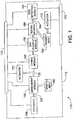
- an exemplary microfluidic network 110 of a microfluidic devicehas a sample input module 150 and reagent input module 152 to allow sample and reagent materials, respectively, to be input to device 110.
- input modules 150, 152are configured to allow automatic material input using a computer controlled laboratory robot.
- Network 110may also include output ports configured to allow withdrawal or output of processed sample from or by microfluidic network 110.
- materialgenerally travels from upstream locations to downstream locations.
- sample materialgenerally travels downstream from an input port to other locations within the microfluidic network. In some cases, however, the direction of flow may be reversed.
- Locations of network 110 downstream from the input moduletypically include process modules 156, 158, 160, 166 and 162 for processing the sample and reagent materials.
- a sampleis subjected to various physical and chemical process steps.
- enrichment module 156receives a particle-containing fluid and prepares a fluid sample having a relatively higher concentration of particles.
- Lysing module 158releases material from particles of an enriched sample, e.g., the module releases intracellular material from cells. Lysing can be accomplished using, for example, thermal, ultrasonic, mechanical, or electrical techniques. Exemplary lysing modules are discussed in U.S. provisional application no. 60/491,269, filed July 31, 2003 , and U.S. patent application no. 10/014,519, filed December 14, 2001 .
- DNA clean-up module 160readies polynucleotides, e.g., DNA, released from the particles for detection.
- DNA clean-up module 160can be configured to prepare a DNA sample for amplification by polymerase chain reaction. Sample DNA processed by cleanup module 160 moves downstream within network 110.
- An exemplary DNA clean-up moduleis discussed in U.S. provisional application no. 60/567,174, filed May 3, 2004 .
- Mixing module 166mixes DNA received from module 160 with reagents from reagent input module 152.
- Typical reagentsinclude PCR primers, reagents, and controls.
- Exemplary reagentsare used in the amplification and detection of GBS bacteria, such as reagents disclosed in U.S. Pat. App. No. 10/102,513, filed March 20, 2002 .
- Reagent materialsmay be loaded during use and/or stored within the microfluidic device during manufacturing. Certain reagent materials can be lyophilized to extend their storage life. Liquid reagents can be stored within a chamber, e.g., a metalized pouch, for mixing with dried reagents.
- a microdroplet having a selected volumeis prepared from fluid released from the chamber within the microfluidic device. The microdroplet is combined with dried reagents to prepare a known concentration of reagent materials.
- Amplification process module 162receives DNA released from sample particles and reagents and detects minute quantities of DNA therein.
- process module 162is configured to amplify the DNA such as by PCR. Detection is typically spectroscopic, as by fluorescence. In some embodiments, the presence and/or abundance of DNA is detected electrochemically.
- Detection module 162typically includes more than one amplification/detection chamber.
- One chambergenerally receives and detects (with optional amplification) DNA released from sample particles.
- Another chambertypically receives and detects (with optional amplification) control DNA, which may be used to indicate whether network 110 is functioning properly.
- Other modules of network 110e.g., reagent and mixing modules 152,166 are configured to accommodate the presence of more than one amplification/detection chamber.
- microfluidic network 110Various modules of microfluidic network 110 are connected, such as by channels 164, to allow materials to be moved from one location to another within the network 110.
- Actuators 168, 170, 172 associated with the microfluidic deviceprovide a motive force, such as an increased gas pressure and/or a decreased gas pressure to move the sample and reagent material along the channels and between modules.
- Some gas actuatorsmove materials by reducing a pressure in a downstream portion of a microfluidic network relative to a pressure in an upstream portion of the microfluidic network. The resulting pressure differential moves the material downstream toward the region of reduced pressure.
- the term vacuumdoes not require the total absence of gas or other material.
- a vacuummeans a region having at least a reduced gas pressure as compared to another region of the microfluidic device, e.g., a partial vacuum.
- the volume of channels and chambers associated with a vacuum actuatoris typically reduced by placing fluid control elements, e.g., valves or gates, as near to the vacuum chamber of the actuator as is feasible.
- First actuator 168 of network 110moves material downstream from enrichment module 156 to lysing module 158.
- a second actuator 170moves material downstream to DNA clean-up module 160.
- actuator 170 or an additional actuatormoves cleaned-up DNA to mixing module 166, where the material mixes with a reagent moved by actuator 172.
- actuator 172moves the mixed material to detection module 162.
- each actuatoris responsible for moving materials within only a subset of the modules of network 110, sample materials can be controlled more precisely than if a single actuator were responsible for moving material throughout the entire device.
- the various functional elements, of microfluidic network 110, including the actuators,are typically under computer control to allow automatic sample processing and analysis.
- microfluidic systemincludes not only a microfluidic device defining a microfluidic network but also the heat sources to operate thermally actuated modules and actuators of the microfluidic device.
- the heat sourcescan be integrated with the microfluidic device or incorporated in another component of the microfluidic system such as a receptacle that receives the microfluidic device during operation.
- the various functional elements, of microfluidic network 110, including the heat sources,are typically under computer control to allow automatic sample processing and analysis. Systems and methods for computer control of microfluidic systems are disclosed in U.S. patent application no. 09/819,105, filed March 28, 2001 .
- actuatorscan manipulate samples within microfluidic devices by reducing a downstream pressure relative to an upstream pressure within the device.
- sucn actuatorsare used m combination with an enrichment module to prepare a sample having an enriched amount of particles.
- the enriched samplecan be delivered to a lysing chamber within the microfluidic device.
- a microfluidic device 50includes a substrate 47 including a first layer 71, a second layer 73, and a third layer 75.
- the layers of substrate 47define a microfluidic network 51.
- Network 51includes channels, modules, and actuators such as, e.g., those of microfluidic network 110 discussed above. At least some components of network 51 are typicaly thermally actuated.
- substrate 47may mate in use with a second substrate 76, which includes heat sources configured to be in thermal communication with thermally actuated components of microfluidic network 51.
- the heat sourcesmay be integral with substrate 47, e.g., substrates 47 and 76 may be integral. Suitable heat sources for actuating thermally actuated components are discussed in copending U.S. application nos. 09/783,225, filed February 14, 2001 and 60/491,539, filed August 1, 2003 .
- network 51includes an input port 54 by which sample material may be introduced to network 51, an enrichment region 56 connected to input port 54 by a channel 58, and a vacuum generator 52 configured to manipulate material within the microfluidic network and connected to enrichment region 56 by a channel 60.
- Port 54may include a fitting 55 to mate with a syringe or other input device and may also include a septum through which a needle or other cannulated sample introduction member may be inserted.
- microfluidic network 51may include other modules or components, e.g., a reaction chamber, a lysing module for releasing material from cells or other biological particles, a DNA clean-up module, a reagent mixing chamber, output port, and the like. These other modules or components are typically disposed downstream of enrichment region 56.
- a typical embodimentincludes a lysing chamber to receive an enriched particle sample from enrichment region 56 and an amplification-detection chamber for amplifying and detecting DNA released from particles of the sample.
- Vacuum generator 52includes a gate 62, a chamber 66, a valve 68, and a port 70, which may be in gaseous communication with the ambient environment around device 50.
- Gate 62is configured in a normally closed state in which gate 62 obstructs passage of material, e.g., sample material and gas, between chamber 66 and upstream portions of microfluidic network 51 such as enrichment region 56. In an open state, gate 62 allows such passage of material.
- Valve 68is configured in a normally open state in which valve 68 allows passage of material, e.g., gas, along a channel 86 between chamber 66 and port 70. In a closed state, valve 68 obstructs passage of material between chamber 66 and port 70. Valve 68 typically includes a chamber 84 and a mass 80 of thermally responsive substance (TRS). In the closed state, the TRS obstructs passage of material whereas in the open state, the TRS is dispersed or withdrawn from the channel to allow passage of material therealong.
- materiale.g., gas
- the obstructing mass of TRScan have a volume of 250 nl or less, 125 nl or less, 75 nl or less, 50 nl or less, 25, nl or less, 10 n1 or less, 2.5 nl or less, 1 nl or less, e.g., 750 pico liters or less.
- some or all of the TRSpasses downstream upon opening the gate or valve.
- the TRSmay pass downstream along the same channel as sample previously obstructed by the TRS.
- the TRSmelts and coats walls of the channel downstream from the position occupied by the TRS in the closed state.
- the wallsmay be at least partially coated for several mm downstream.
- the TRSdisperses and passes downstream as particles too small to obstruct the channel.
- Exemplary gates and valves including a mass of TRSare disclosed in U.S. Patent no. 6,575,188, issued June 10, 2003 .
- the first temperaturemay be about 25° C or less and the second higher temperature may be at least about 40° C.
- the second higher temperaturemay be a melting temperature or a glass transition temperature of the TRS.
- Suitable materialsinclude wax, a polymer, or other material having a melting point (or glass transition temperature) of at least 50°C, e.g., of at least 75° C.
- Preferred TRS materialshave melting points (or glass transition temperatures) of less than 200° C, e.g., less than 150° C.
- Typical TRS materialsare hydrophobic but may be hydrophilic.
- Raising a temperature within chamber 84increases a pressure therein.
- the pressure within chamber 84moves TRS 80 into channel 86 connecting port 70 and chamber 66 thereby obstructing the passage of material, e.g., gas, along channel 86.
- Substrate 76includes a heater 82 configured to be in thermal contact with both chamber 84 and TRS 80 when substrates 76 and 71 are mated. Actuating heater 82 raises both the temperature within chamber 84 and the temperature of TRS 80 to the second temperature.
- Gate 62is typically a thermally actuated gate including a mass of TRS 74.
- heater 78 and gate 62are disposed in thermal contact. Actuating heater 78 raises the temperature of TRS 74 to the second temperature.
- the TRS 74when at the first temperature, prevents the passage of material between chamber 66 and upstream portions of network 51.
- the temperature of TRS 74is raised to the second temperature, such a pressure differential is typically sufficient to move and/or disperse TRS 74 allowing material, e.g., gas, to pass into chamber 66 from upstream portions of network 51.
- chamber 66is configured to maintain a pressure that is less than about 90%, less than about 80%, less than about 70%, less than about 60%, less than about 50%, or less than about 35% of the pressure acting upon the opposite side of valve 68.
- the pressure acting upon the opposite side of valve 68is typically the ambient pressure around device 50, e.g., about 1 atmosphere.
- the reduced pressure within chamber 66can be maintained for at least 15 seconds, at least 30 seconds, at least 60 seconds, at least 120 seconds, e.g., at least 300 seconds.
- Valves and gates in accord with the present inventionmay have identical structures with the exception that, unless otherwise specified, a valve is normally configured in an open state and a gate is normally configured in a closed state.
- a method for preparing a vacuum within chamber 66typically includes the at least partial evacuation of gas from chamber 66 and the sealing of the evacuated chamber to prevent material from re-entering the chamber.
- Evacuationis generally achieved by heating chamber 66.
- chamber 66is in thermal contact with a heat source 41 of substrate 76. Actuation of the heat source 41 raises the temperature of material present within chamber 66.
- the material within the chambermay include, e.g., a gas and/or vaporizable material such as a liquid or a material that is capable of sublimation at a temperature of between about 50° C and about 200° C.
- Vacuum generator 52is typically used to manipulate materials within network 51 of device 50. In some embodiments, vacuum generator cooperates with enrichment region 56 to prepare an enriched sample. The enrichment region is now discussed in greater detail.
- Enrichment region 56includes a retention member 94, a valve 85, and a downstream gate 88.
- Retention member 94generally includes a filter to selectively retain particles of a particle-containing sample as compared to fluid (e.g. a liquid) of the particle-containing sample, such as to allow the passage of fluid but limit or prevent the passage of the particles.
- fluide.g. a liquid
- retention member 94allows the passage of fluid therethrough but retains particles by size exclusion.
- retention member 94allows fluid to exit enrichment region 56 by passing through retention member 94 but retains particles within the enrichment region. Fluid that passes through retention member 94 enters a reservoir 98 configured to contain such fluid.
- retention membersare configured to retain, such as by size exclusion, bacteria, e.g., GBS from culture and clinical samples.
- An exemplary retention memberis a polycarbonate track-etch filter defining, e.g., 0.6 ⁇ m pores, such as is available from Poretics.
- Enrichment region 56may communicate with retention member 94 via a hole 89, which may open to a cavity 91 defined at least in part by a surface 97 of retention member 94. Cavity 91 allows the particle-containing sample to contact retention member 94 over a surface area that is greater than a surface area of hole 89. Cavity 91 may be tapered as shown to facilitate entry of fluid and particles to and removal of fluid and particles from cavity 91. As an alternative to cavity 91, hole 89 may communicate with a network of channels that distribute fluid over a surface 97 of retention member 94.
- Reservoir 98may be sealed, such as by a fluid impermeable membrane (not shown), to prevent fluid expelled through retention member 94 from leaking into the surrounding environment.
- the sealed volume of the reservoirmay be as great as or greater than the total internal volume of enrichment chamber 56 and portions of network 51 downstream thereof.
- a retention member support 96helps retain retention member 94 in position against internal pressure created by the introduction of sample and the passage of fluid through retention member 94.
- Support 96may be a grid fabricated as part of substrate layer 73.
- Gate 88has a normally closed state to obstruct passage of material between enrichment region 56 and downstream portions of microfluidic network 51. Gate 88 has an open state in which material may pass from enrichment region 56 to downstream portions of network 51. Gate 88 may be a thermally actuated gate including a mass 90 of TRS and actuated by a heat source 92 of substrate 76.
- Valve 85has a normally open state in which material may pass between upstream portions of microfluidic network 56 and enrichment region 56. Valve 85 has a closed state, which obstructs material from passing between enrichment region 56 and upstream regions of microfluidic network 56. Valve 85 may be a thermally actuated valve including a mass 89 of TRS and a chamber 87. Substrate 76 includes a heat source 93 configured to actuate valve 85 as discussed for valve 68.
- Enrichment region 56 of device 50may be operated as follows.
- a particle containing fluid sampleis introduced to network 51, e.g., via port 54, such as by using a syringe or other sample introduction device.
- the amount of sample introducedmay be at least, e.g., 250 microliters, at least 500 microliters, or at least 1000 microliters.
- the amount of fluid, e.g., liquid, introducedmay be, e.g., less than 10,000 microliters, less than 5,000 microliters, or less than 2,500 microliters.
- Enrichment region 56is typically configured so that (with downstream gate 90 closed) fluid entering device 50 must pass through retention member 94 to exit the enrichment region.
- the particle-containing fluidic samplepasses along channel 58 into enrichment region 56.
- Retention member 94spatially separates at least some and preferably most of the fluid of the received fluidic sample from particles of the received fluidic sample. For example, liquid of a fluidic sample may pass through or beyond at least surface 97 of retention member 94 whereas retention member 94 retains particles of the fluidic sample, such as at surface 97 thereof. Fluid, e.g., liquid, that passes through or beyond surface 97 exits enrichment region 56 and may pass into reservoir 98. Fluid that has passed beyond surface 97 may be described as having been expelled from the microfluidic network.
- Retention member 94retains particles of the fluid sample, such as by size exclusion and/or by adsorption and/or absorption of the particles.
- reservoir 98contains fluid of the sample whereas particles of the sample are retained within enrichment region 56, such as at surface 97 of retention member 94.
- some of the fluid of the fluidic samplemay remain within the enrichment region 56 (interior to surface 97) and in contact with the retained particles.
- This amount of fluidis typically less than about 50%, less than about 25%, less than about 10%, less than about 5%, e.g., less than about 2% relative to the total amount of fluid received by enrichment region 56.
- the total amount of fluid received by the enrichment region 56is typically between about 1 and 10 ml.
- valve 85is actuated to the closed state thereby preventing passage of material between enrichment region 56 and upstream poritions of network 51, e.g., port 54. Particles retained by the filter may be moved away from the filter by causing fluid to pass into enrichment region through retention member 94 along a path that is substantially opposite to the path followed by fluid of the fluidic sample in passing beyond surface 97 and into reservoir 98.
- device 50is configured such that a gas pressure downstream of enrichment region 56, e.g., downstream of gate 88, is less than a gas pressure external to surface 97 of retention member 94.
- a gas pressure downstream of enrichment region 56e.g., downstream of gate 88
- the pressure differentialcauses some fluid, e.g., fluid within reservoir 98, e.g., liquid of the particle-containing sample, to enter enrichment region 56, combine with retained particles therein and move the particles away from the retention member 94.
- a vacuummay be used to obtain the pressure differential.
- a vacuummay be prepared as follows. With valve 68 (of vacuum generator 52) configured in the open state and at least one gate intermediate vacuum generator gate 52 and enrichment region 56 (e.g., gate 62) configured in the closed state, heat source 41 is actuated thereby raising a temperature of material within chamber 66. Gas present within the chamber expands and at least some of the expanded gas exits network 51 via port 70. If a liquid is present within chamber 66, the liquid may vaporize with at least some of the vapor also exiting via port 70. Similarly, the elevated temperature may sublimate a solid present within chamber 66. Once the temperature within chamber 66 has been raised to a given temperature for a given time, valve 68 is closed and the temperature within chamber 66 is allowed to decrease.
- valve 68of vacuum generator 52
- enrichment region 56e.g., gate 62
- the pressuree.g. the total gas and vapor pressure therein, decreases and creates a pressure differential between chamber 66 and enrichment region 56.
- chamber 66 and enrichment region 56are brought into gaseous communication such as by actuating any closed gates (e.g., gate 62 and/or 90) along channel 60.
- any closed gatese.g., gate 62 and/or 90
- a pressure differentialis created between a pressure of gas above fluid in reservoir 98 and a pressure within enrichment region 56.
- the pressure differentialdraws a portion of the fluid present in reservoir 98 through retention member 94 and into enrichment region 56.
- the fluidpreferably passes through retention member 94 in an opposite direction from the direction taken by fluid during expulsion through retention member 94.
- the direction of flowmay be substantially orthogonal to layer 73.
- the direction of flowmay be substantially orthogonal to a plane defined by network 51.
- the fluid entering enrichment region 56combines with particles retained by retention member 94 during sample introduction and forms an enriched particle-containing sample typically including a smaller volume fluid, e.g., liquid, than was introduced into network 51 and a substantial portion of the particles that were retained by retention member 94.
- the amount of fluid that passes into, e.g., back into, enrichment region 56 through retention member 94is typically less than 50%, less than 10%, less than 2.5%, or less than 1% of the volume of fluid, e.g., liquid, introduced with the sample.
- the amount of fluid, e.g., liquid, that passes into enrichment region 56 through retention member 94may be less than 50 microliters, less than 25 microliters, less than 15 microliters, less than 10 microliters, or less than 5 microliters.
- the retention member 94no longer retains the particles of the enriched particle-containing sample so that the enriched particle-containing sample moves away from the retention member.
- the fluid expelled through retention member 94 and into reservoir 98may be replaced with other fluid, such as fresh buffer or a different buffer.
- the fluid passing into enrichment region 56 through retention member 94includes at least some and perhaps substantially all of the other fluid.
- the fluid entering into the enrichment region 56 through retention member 94is not limited to the fluid that was expelled upon introducing the particle-containing sample.
- the pressure differentialis typically sufficient to also move the enriched fluid into a downstream portion of microfluidic network 51.
- the downstream movementcan be accomplished using another vacuum generator or a source of positive pressure source in addition to or as an alternative to vacuum generator 52.
- enrichment ratiosi.e., the volume concentration of particles in the enriched fluid relative the volume concentration of particles in the introduced fluid, are at least 5, at least 10, at least 25, at least 50 or at least 100.
- the enriched fluidic samplemay be withdrawn from network 51 or subjected to further processing and or analysis therein.
- a microfluidic device 200receives a sample, e.g., a particle-containing sample, and enriches the sample to prepare an enriched sample including a greater relative concentration of the particles.
- device 200includes a microfluidic network 201 including an input port 204, a channel 205 along which sample material received via input port 204 may pass, a vent 206 configured to allow gas accompanying the received sample material to exit network 201, and a channel 207 disposed downstream of vent 206.
- An enrichment region 202is located downstream of channel 207.
- Input port 204can include a fitting 232 ( Fig. 5 ) configured to mate with a syringe or other input device.
- Vent 206may include a gas permeable hydrophobic membrane, e.g., a porous polytetrafluoroethylene membrane available from W. L. Gore, Inc.
- Channels 205 and 207are separated by a valve 208, which generally has a normally open state configured to allow at least downstream passage of material from channel 205 to channel 207.
- Valve 208can be actuated to a closed state configured to obstruct passage of material between enrichment region 202 and portions of network 201 upstream of valve 208.
- Valves of device 200may be configured as thermally actuated valves discussed for device 50.
- Enrichment region 202which may be configured as enrichment region 56, receives sample material introduced via port 204 and prepares an enriched sample enriched in a desired particle.
- Enrichment region 202includes a retention member 94, a retention member support 202, which may be configured as support 96, and a reservoir 234, which may be configured as reservoir 98.
- Network 201also includes a channel 209 located downstream of enrichment region 202 to receive enriched sample material therefrom.
- Channel 209includes a gate 216 configured to selectively permit the downstream passage of material between enrichment region 202 and portions of network 201 downstream of gate 216.
- Gate 216has a normally closed state which obstructs the passage of material, e.g., enriched sample and/or gas, between enrichment region 202 and portions of network 201 downstream of gate 216. Gate 216 may be actuated to an open state in which material may pass between enrichment region 202 and downstream portions of network 201. Gates of device 200 may be configured as thermally actuated gates discussed for device 50.
- materiale.g., enriched sample and/or gas
- Gate 216is connected to downstream portions of network 201 via a channel 219.
- network 201includes an output port 210a connected to channel 219 via a channel 220.
- Enriched sample materialmay be withdrawn manually or output automatically from port 210a by device 200.
- a gate 212 having a normally closed stateselectively obstructs or permits passage of material between channel 220 and output port 210a.
- Network 201Other downstream portions of network 201 are connected to channel 219 via a channel 218.
- an output port 210bis connected to channel 218 via a channel 224.
- Enriched sample materialmay be withdrawn manually or output automatically from port 210b by device 200.
- a gate 222 having a normally closed stateselectively obstructs or permits passage of material between channel 218 and output port 210b.
- Device 200can be configured to enrich a sample as follows. Gate 216 is configured in the closed state obstructing passage of material between enrichment region 202 and downstream portions of network 201. Valve 208 is configured in the open state. An amount of sample material is introduced to channel 205, such as by using a syringe configured to mate with fitting 232. The amount of sample introduced may be as described for device 50. The introduced sample material passes vent 206, which allows gas to exit channel 205 but resists the exit of fluid and particles of the sample material. Sample material passes downstream of vent 206 and is received by enrichment region 202.
- Retention member 94allows fluid of the sample material to exit enrichment region 202 but retains particles, such as by allowing the passage of fluid but limiting or preventing the passage of the particles as described above.
- the fluidis expelled through filter 94 and into reservoir 234, which may be sealed as for reservoir 98. Particles of the sample are retained within enrichment region 202 as described above.
- Network 201may be configured to manipulate, e.g., move, material therein by using pressure differentials therein.
- the creation of a relatively decreased pressure in a first portion of the network relative to a pressure in a second portion of the networkcan be used to urge material from the second toward the first portions of the network.
- the relatively decreased pressurecan be created by a decrease in the absolute pressure in the first portion and/or an increase in the absolute pressure in the second portion.
- device 200includes a vacuum generator 215 configured to create a decreased pressure at locations downstream of enrichment region 202 relative to a pressure within enrichment region 202 and/or a pressure above fluid within reservoir 234.
- Device 200can use the pressure differential to move enriched sample material from enrichment region 202 to downstream portions of network 201.
- Vacuum generator 215includes a chamber 214, a port 230, and a valve 208.
- Chamber 214communicates with channel 220 (and therefore channel 209 and enrichment region 202 when gate 216 is in the open state) via a channel 218 and a channel 226.
- Chamber 214communicates with port 230 via a channel 228.
- Valve 208permits selective obstruction of channel 228 so that the passage of material, e.g., gas, between chamber 214 and port 230 may be obstructed.
- Port 230 and valve 208may be configured and operated as port 70 and valve 68 respectively.
- Device 200may be configured for creating a partial downstream vacuum as follows.
- Gate 209is configured in the closed state thereby preventing or at least limiting the passage of gas between enrichment region 202 and chamber 214. If either of output ports 210a, 210b are present, gates 212, 222 are configured in the closed state, thereby preventing or at least limiting the passage of gas into or out of network 201 via ports 210a, 210b.
- Valve 208is configured in the open state thereby allowing the passage of material, e.g., gas between chamber 214 and port 230, which typically provides the only passage for gas to exit network 201 from chamber 214. Gas present within chamber 214 is heated causing the gas to expand. At least some of the expanded gas exits chamber 214 (and therefore network 201) via port 210. When the gas has been expanded to a desired extent, valve 208 is closed and the remaining gas is allowed to cool causing a partial vacuum to form within chamber 214.
- materiale.g., gas between chamber 214 and
- Device 200may be configured to use a partial vacuum with chamber 214 to prepare an enriched sample as follows.
- a particle-containing fluid sampleis introduced as described above so that retention member 94 retains particles. Fluid is present within reservoir 234. The fluid may include fluid expelled through retention member 94 and/or fresh or additional fluid as described for device 50.
- the partial vacuum within chamber 214is prepared.
- Gate 216is actuated, such as by heating a TRS thereof, thereby placing chamber 214 in communication with enrichment region 202 and creating a pressure differential between the pressure of a gas above the fluid in reservoir 234 and chamber 214.
- the pressure differentialoperates as discussed for enrichment region 56 to withdraw an amount of fluid back through retention member 94 and back into enrichment region 202 to prepare an enriched particle containing sample.
- the enriched samplemay be prepared in the same amounts and with the same properties as for device 50.
- the pressure differential between chamber 214 and above fluid in reservoir 234is typically sufficient to also move the enriched fluid into a downstream portion of microfluidic network 201.
- the downstream movementcan be accomplished using another vacuum generator or a source of positive pressure source in addition to or as an alternative to vacuum generator 215.
- Gate 216may be re-sealed thereby preventing the passage of additional material between enrichment region 202 and downstream portions of network 201.
- Vacuum generator 215may be actuated a second time to move the enriched sample again.
- at least one of gates 212, 222may be actuated to place ports 210a, 210b in communication with network 201.
- Gas within chamber 214is heated creating a pressure increase that drives the enriched sample toward ports 210a, 210b.
- network 201may contain additional modules, e.g., a lysing module, a reagent mixing module, a reaction module, etc., for subjecting the enriched sample to further processing within network 201. Additional vacuum generators or pressure generators may be added to effect further movement of the enriched and or processed sample within these modules.
- a microfluidic device 600is configured to receive an amount of a particle-containing fluidic sample and to prepare an enriched sample including a greater abundance of the particles.
- the preparation of the enriched sampleincludes spatially separating particles of the particle-containing sample from (at least some) fluid of the sample, e.g., liquid of the sample.
- Device 600uses pressure created during the spatial separation to recombine a subset of the fluid that was separated from the particles with the particles.
- Device 600includes a microfluidic network 601 including an input port 654, a sample enrichment region 602 connected to the sample port by a channel 605, a pressure actuator 607 located downstream of enrichment region 602 and connected thereto by a channel 609, and an output port 611 in communication with channel 609.
- Channel 605includes a vent 606 configured to allow gas to exit channel 605.
- Vent 606may have features of vent 206 discussed above.
- Channel 605, upstream of enrichment region 602,includes a valve 608 to selectively obstruct passage of material between input port 654 and enrichment region 602.
- Valve 608may have features of valve 208 or other valves (or gates) discussed herein.
- Valve 608is preferably configured to have a normally open state that allows material to pass along channel 605.
- device 600can include a 1-way valve configured to allow sample to enter channel 605 and pass downstream but configured to limit or prevent material, e.g., gas, from passing upstream from from chamber 699 and exiting device 600 via port 654.
- An exemplary valveis a duckbill valve available from Minivalve International, Oldenzaal, The Netherlands. Such a valve can be located at port 654, e.g., in combination with fitting 655, or disposed along channel 605.
- Channel 609, downstream of enrichment region 602,includes a gate 616 to selectively allow passage between enrichment region 602 and downstream locations of microfluidic network 601.
- Gate 616may have features of gate 216 or other gates (or valves) discussed herein.
- Gate 616is generally configured to have a normally closed state that obstructs passage of material between enrichment region 602 and downstream locations of network 601.
- Network 601includes a passage 635 that connects output port 611 and channel 609.
- the passage 635includes a gate 637 to selectively obstruct or allow passage between channel 609 and output port 611.
- Gate 635may have features of gate 216 or other gates (or valves) discussed herein.
- Gate 635is generally configured to have a normally closed state that obstructs passage of material between channel 609 and output port 611.
- Pressure actuator 607includes a gate 639 to selectively allow passage between actuator 607 and channel 609.
- Gate 639may have features of gate 216 or other gates (or valves) discussed herein.
- Gate 639is generally configured to have a normally closed state that obstructs passage of material between actuator 607 and channel 609.
- Enrichment region 602includes a retention member 694 to spatially separate particles of a particle-containing sample from fluid of the particle-containing sample.
- Retention member 694preferably allows fluid, e.g., gas and/or liquid, to pass therethrough and into reservoir 698.
- Retention member 694typically retains particles within a cavity 691 that is at least in part defined by a surface 697 of retention member 694.
- Enrichment region 602may have features of enrichment region 56 or other enrichment regions discussed herein.
- Retention member 694may have features of retention member 94 or other retention members discussed herein.
- retention member 694may operate to allow the passage of fluid but limit or prevent the passage of the particles by size exclusion, binding, and/or adsportion.
- reservoir 698defines a substantially gas impermeable chamber 699. Fluid that enters chamber 699, such as by passing through retention member 694, decreases a free volume thereof and increases a pressure therein. Thus, the pressure within chamber 699 is greater in Fig. 6d than in 6c because more fluid has been introduced to the chamber 699. The force needed to overcome the introduction of fluid to chamber 699 is provided during the introduction of sample to device 600.
- Chamber 699may include a valve, e.g., a pressure relief valve (not shown), configured so that each introduction of sample into device 600 creates the same pressure within chamber 699.
- a pressure relief valvee.g., a pressure relief valve (not shown)
- Exemplary pressure relief valvesare umbrella valves available from Minivalve International.
- a pressure relief valvecan be used in any pressure chamber of devices herein.
- the relief valveopens when the pressure differential between pressure within chamber 699 and pressure external to chamber 699 exceeds about 0.5 psi, about 1 psi, about 2 psi, or about 3 psi. Larger volume chambers typically have valves that open at lower pressures than smaller volume chambers.
- Device 600may be operated as follows.
- a particle-containing sampleis introduced to device 600, such as by using a sample introduction device, e.g., a syringe 697, mated with fitting 655 of input port 654.
- a sample introduction devicee.g., a syringe 697
- Pressure created by the sample introduction devicedrives fluid of the sample through retention member 694 and into chamber 699 of reservoir 698. As discussed above, the entry of fluid into chamber 699 increases the pressure therein.
- Retention member 694retains particles of the sample within cavity 691 of enrichment region 602.
- the enrichment regionmay be sealed to prevent pressure created within chamber 699 from being vented or driving material out of enrichment region 602.
- valve 608may be actuated to the closed state to prevent passage of material between input port 654 and enrichment region 602 along channel 605. With both valve 608 and gate 616 in the closed state, device 600 maintains the pressure within chamber 699.
- gate 616is actuated to the open state thereby providing a passage for material to exit chamber 699.
- the relatively greater pressure within the chamberdrives fluid therein through retention member 694 and into cavity 691 of enrichment region 602.
- the fluidpasses through retention member 694 in an opposite direction from the fluid that entered chamber 699 through retention member 694.
- the amount of fluid, e.g., liquid, that passes into enrichment region 602 through retention member 694is typically less than 50%, less than 10%, less than 2.5%, or less than 1% of the volume of fluid, e.g., liquid, introduced with the sample.
- the amount of fluid, e.g., liquid, that passes into enrichment region 602 through retention member 694may be less than 50 microliters, less than 25 microliters, less than 15 microliters, less than 10 microliters, or less than 5 microliters.
- device 600prepares an enriched particle-containing sample including particles of the particle-containing sample and a subset of the fluid that was originally introduced to device 600.
- a volume of a downstream portion of network 601may determine the volume of fluid (e.g., the volume of the subset) that recombines with the particles.
- the downstream portionis defined between enrichment region 602 and a downstream vent.
- downstream channel 609includes a vent 613, e.g., a gas-permeable hydrophobic membrane, that allows gas to exit network 601 but substantially prevents liquid from exiting network 601.
- vent 613e.g., a gas-permeable hydrophobic membrane
- channel 609Upon the enriched sample material reaching vent 613, channel 609 is filled with enriched sample material and the downstream passage of additional material from enrichment region 602 is limited or prevented.
- the downstream volume of channel 609defines the volume of liquid that may exit chamber 699 and recombine with particles to prepare the enriched sample material.
- the pressure within chamber 699may be vented, e.g., by re-opening valve 608.
- gate 616(or a valve downstream of chamber 699, not shown) may be re-closed (or closed) to isolate chamber 699 from channel 609.
- Device 600may include additional modules, such as one or more of those of system 110 of Fig. 1 . Such modules are preferably configured to further process the enriched sample, such as by lysing cells thereof, removing polymerase chain reaction inhibitors, mixing the enriched sample with reagent, and the like. For devices including such modules, passage 635 may connect with these modules rather than leading to output port 611. In such embodiments, device 600 may be configured to drive a known volume of the enriched sample material downstream toward the additional modules. Alternatively, device 600 may be configured to expel a known amount of the enriched sample material from the device via port 611.
- a known amount of enriched sample materialmay be driven downstream or expelled as follows.
- pressure actuator 607is actuated to generate pressure therein.
- actuator 607may include a gas chamber in thermal communication with a heat source.
- the heat sourcesmay be integral with device 600 or located in a separate substrate 671 as for device 50. In any event, heat from the heat source expands gas present in the chamber of actuator 607 and generates pressure.
- gates 637 and 639are opened allowing pressure within the actuator 607 to move the enriched sample.
- the volume of enriched sampleis determined by the volume of network 601 downstream of actuator 607 and upstream of vent 613.
- device 600may be configured to prepare and/or deliver an enriched sample having a known volume. The volume of a prepared and a delivered sample need not be the same.
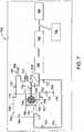
- a microfluidic device 700receives an amount of a particle-containing fluidic sample and prepares an enriched sample including a greater abundance of the particles.
- the preparation of the enriched sampleincludes spatially separating particles of the particle-contaiming sample from fluid of the sample.
- Device 700uses pressure created during the spatial separation to manipulate sample and/or reagent material, such as to move such materials about device 700.
- Device 700includes a microfluidic network 701 including an input port 754, an enrichment region 756 in communication with input port 754 by a channel 702, and a reservoir 798 defining a chamber 799 to receive fluid from enrichment region 756.
- Channel 702 upstream of enrichment region 756,includes a valve 708 to selectively obstruct passage of material between input port 754 and enrichment region 756.
- Valve 708may have features of valve 208 or other valves (or gates) discussed herein.
- Valve 708is has a normally open state that allows material to pass along channel 702.
- Enrichment region 756includes a retention member 794 to spatially separate particles of a particle-containing sample from fluid of the particle-containing sample.
- Retention member 794allows fluid, e.g., gas and/or liquid, to pass therethrough and into reservoir 798 while retaining particles.
- Enrichment region 756may have features of enrichment region 56 or other enrichment regions discussed herein.
- Retention member 794may have features of retention member 94 or other retention members discussed herein.
- Chamber 799defines a first portion 791 and a second portion 793 separated by a liquid barrier, e.g., an internal wall 789, configured to allow gas to pass between portions 791, 793 but to prevent liquid from passing between these portions of chamber 799.
- a channel 711extends downstream from first portion 791.
- a channel 723extends downstream from an outlet 719 of second portion 793 and joins channel 711 at an intersection 713.
- Channel 723includes a gate 725 to selectively obstruct or allow passage between second portion 793 of chamber 799 and downstream portions of channel 723.
- Gate 725may have features of gate 216 or other gates (or valves) discussed herein.
- Gate 725has a normally closed state that obstructs passage.
- a vent 755is in gaseous communication with channel 723.
- a valve 757having a normally open state, is configured to selectively allow or obstruct passage of gas between channel 723 and vent 755.
- Channel 711includes a gate 716 and a gate 759 to selectively obstruct or allow passage between enrichment region 756 and downstream locations of microfluidic network 701.
- Gates 716 and 759may have features of gate 216 or other gates (or valves) discussed herein.
- Gates 716 and 759are typically configured to have a normally closed state that obstructs passage of material between enrichment region 756 and downstream locations of network 701.
- Downstream locations of network 701typically include lysing module 158, DNA clean-up module 160, detection module 162, and reagent module 152.
- Device 700may be operated as follows.
- a particle-containing sampleis introduced, such as by using a sample introduction device, e.g., a syringe, mated with a fitting 755 of input port 754.
- a sample introduction devicee.g., a syringe
- Pressure created by the sample introduction devicedrives fluid of the sample through retention member 794 and into first portion 791 of chamber 799 of reservoir 798. Entry of fluid into first portion 791 of chamber 799 increases the pressure within chamber 799.
- Retention member 794retains particles of the sample within enrichment region 756.
- the enrichment regionmay be sealed to prevent pressure created within chamber 799 from being vented or driving material out of enrichment region 756.
- valve 708may be actuated to the closed state to prevent passage of material between input port 754 and enrichment region 756 along channel 702. With valve 708 and gates 716,725 in the closed state, device 700 maintains the pressure within chamber 799.
- gate 716is actuated to the open state thereby providing a passage for material to exit chamber 799.
- the relatively greater pressure within the chamberdrives fluid therein through retention member 794 and into enrichment region 756.
- the fluidpreferably passes through retention member 794 in an opposite direction from the fluid that entered chamber 799 through retention member 794.
- the amount of fluid, e.g., liquid, that passes into enrichment region 756 through retention member 794is typically less than 50%, less than 10%, less than 2.5%, or less than 1% of the volume of fluid, e.g., liquid, introduced with the sample.
- the amount of fluid, e.g., liquid, that passes into enrichment region 756 through retention member 794may be less than 50 microliters, less than 25 microliters, less than 15 microliters, less than 10 microliters, or less than 5 microliters.
- device 700prepares an enriched particle-containing sample including particles of the particle-containing sample and a subset of the fluid that was originally introduced to device 700.
- pressure within chamber 799also drives the enriched particle-containing sample toward downstream portions of network 701.
- a volume of the enriched particle-containing sample driven downstreamis determined by a volume of a downstream portion of network 701.
- pressure within chamber 799drives at least a portion of the enriched particle sample along channel 711 and into channel 723 beyond intersection 713.
- Enriched sampleis driven along channel 723 until a downstream terminus of enriched sample reaches vent 755 inhibiting further movement of the sample.
- the volume of the enriched sampleis substantially determined by a volume of channel 723 intermediate vent 755 and gate 759.
- gate 716may be re-closed or a valve (not shown) located along channel 711, may be actuated to obstruct passage of material between channel 723 and enrichment region 756. Then, gates 725 and 759 are actuated. Opening gate 725 places intersection 713 between channels 711 and 723 in communication with second portion 793 of chamber 799 via outlet 719. With gate 725 open, pressure within chamber 799 drives material further downstream of intersection 713. For example, the pressure may drive material toward lysing module 158.
- Chamber 799 of device 700may include one or more additional output ports configured to allow pressure within chamber 799 to be used to manipulate and/or move sample, reagent, or other materials elsewhere within network 701.
- outlet 717communicates with channel 733 which itself intersects with channel 709 upstream of lysing region 158.
- a gate 735selectively obstructs or allows passage of material between outlet 717 and channel 733.
- a gate 737selectivel obstructs or allows passage of material between channels 709 and 733. Upon preparation of a lysed sample, gates 735,737 are opened whereupon pressure from chamber 799 moves the lysed sample downstream of lysing chamber 158.
- a microfluidic device 300includes a sample enrichment region 302, a port 304 for introducing sample material to device 300, a port 306 for the output of processed sample material, a channel 308 connecting the enrichment region 302 and, and a valve 310 for obstructing passage of material along channel 308 between enrichment region 302 and port 304.
- a given amount of sample materialis introduced via port 304, which may be configured to mate with a standard syringe.
- the amount of sample introduceddepends upon the analysis and may be, e.g., at least about 0.25 ml, at least about 0.5 ml, at least about 1 ml, and, e.g., less than about 5 ml, less than about 2.5 ml, or less than about 1.5 ml.
- Sample materialpasses along channel 308 to enrichment region 302.
- the fluidtravels into the concentration region (including a circular filter whose center is typically free and whose edge 309 is secured to the chip) and through the filter leaving the cells or other particles of interest behind at an internal surface of the filter.
- the waste fluidmay pool on top of the device, and can be discarded, assuming a thin meniscus of liquid remains on the top of the filter to prevent drying and to provide a reservoir from which to backflow.
- the useractuates the valve 310, thus obstructing the passage of material between port 304 and enrichment region 302.
- the tapeis removed, and an external device, e.g., a pipette or syringe, is used to backflow the some of the liquid of the sample back through the filter to re-entrain the cells.
- an external devicee.g., a pipette or syringe
- less than 25%, less than 10%, less than 5%, less than 2.5%, or less than 1% of the fluid introduced with the particlesre-entrains the particles.
- Microfluidic DeviceIncluding A Thermally Actuated Lysing Module
- a microfluidic device 1000includes a microfluidic network 1001 having a input port 1002 leading to a channel 1003 including a vent 1004 and a valve 1005, which has a normally open position but can be closed to obstruct passage of material between channel 1003 and a lysing region 1006 downstream of valve 1005.
- a downstream portion 1020 of lysing region 1006joins a waste channel 1008, which leads to a waste port 1009.
- a valve 1011selectively allows or obstructs passage of material along channel 1008 to waste port 1009.
- a gate 1022selectively obstructs or allows passage of material downstream from lysing region 1006.
- thermopnuematic actuator 1014generates a gas pressure sufficient to move material, e.g., a lysed sample, downstream from lysing region 1006 and into channel 1018.
- Actuator 1014typically operates by generating an upstream pressure increase but device 1001 can be configured with an actuator that provides a downstream pressure decrease, e.g., a partial vacuum, to move material downstream from lysing region 1006.
- a gate 1071selectively obstructs or allows passage of material between actuator 1014 nad lysing chamber 1006.
- Network 1001includes a reagent input port 1032 leading to a channel 1033 including a vent 1034 and a valve 1035, which has a normally open position but can be closed to obstruct passage of material between channel 1033 and a reagent metering chamber 1024 downstream of valve 1035.
- a downstream portion 1028 of reagent metering chamber 1024joins a waste channel 1038, which leads to a waste port 1039.
- a valve 1031selectively allows or obstructs passage of material along channel 1038 to waste port 1039.
- a gate 1042selectively obstructs or allows passage of material downstream from reagent metering chamber 1024.
- thermopnuematic actuator 1022generates a gas pressure sufficient to move material, e.g., an amount of reagent, downstream from reagent metering chamber 1024 and into channel 1018.
- Actuator 1022typically operates by generating an upstream pressure increase but device 1001 can be configured with an actuator that provides a downstream pressure decrease, e.g., a partial vacuum, to move material downstream from reagent metering region 1024.
- a gate 1073selectively obstructs or allows passage of material between actuator 1022 and reagent metering region 1024.
- downstream portion 1020 of lysing region 1006 and downstream portion 1028 of reagent metering chamber 1024lead to an intersection 1019, which is the upstream terminus of a channel 1018.
- the channel 1018leads to a reaction chamber 1048 having an upstream terminus defined by a valve 1050 and a downstream terminus defined by a valve 1052.
- Valves 1050, 1052can be closed to prevent material from exiting reaction chamber 1048.
- a vent 1054allows degassing, debubbling of material passing along channel 1018 into chamber 1048.
- a vent 1055prevents pressure buildup from preventing material from entering chamber 1048.
- valve 1011includes a mass of TRS 1059 and a pressure chamber 1057. Increasing a temperature of of TRS 1059 and a pressure within chamber 1057 drives TRS 1059 into channel thereby obstructing the channel.
- Gate 1022includes a mass of TRS 1061 that obstructs passage of material from lysing region 1006 to intersection 1019. Raising a temperature of TRS 1061 allows upstream pressure (or a downstream partial vacuum) to move material from lysing region into intersection 1019 and channel 1018.
- Vents of network 1001typically include a porous hydrophobic membrane as discussed for vents of other devices herein. The vents allow gas to escape network 1001 put inhibit or prevent liquid from escaping. ,
- Device 1000is typically configured to receive a cell containing sample, lyse the cells to release intracellular material, combine the intracellular material with reagents, e.g., reagents suitable for PCR amplification and detection, deliver the combined reagents and intracellular material to the reaction chamber 1048, amplify DNA present in the intracellular material, and detect the presence or absence of a particular type of cell, e.g., group B strept, based upon the detected DNA.
- reagentse.g., reagents suitable for PCR amplification and detection
- exemplary operation of device 1000includes introducing a volume of particle-containing sample into network 1001 via inlet 1002.
- Sample materialmoves along a channel 1003 toward lysing chamber 1006.
- Gas, such as air bubbles possibly introduced with the sampleare vented from the microfluidic network at vent 1004.
- Sample materialenters and fills lysing chamber 1006.
- Gate 1022is closed thereby preventing passage of sample downstream toward intersection 1019. Excess sample material travels along waste channel 1008 to a waste port 1009, which may provide passage to a waste chamber.
- the volume remaining within the microfluidic network and the position occupied by the remaining volumeis preferably determined by the volume of the respective channels and the position of any vents ( Fig. 9b ).
- the vent 1004prevents an upstream portion of the sample material from being positioned downstream of an upstream opening 1012 of lysing chamber 1006.
- lysing chamber 1006is completely filled with sample material ( Fig. 9b ).
- Reagent materialsmay be introduced to network 1001 via port 1032. Waste channel 1038 and waste port 1039 cooperate with reagent metering region 1024 to deliver an amount reagent materials and position the reagent materials in the same way that waste channel 1008 and waste port 1009 cooperate with lysing chamber 1006 to deliver an amount of sample and position the sample. Reagent materials may also be stored on the device during manufacture as discussed elsewhere herein.
- valves 1011,1005are closed. Closure of valves 1011,1005 isolates sample within lysing chamber 1006 from the atmosphere surrounding device 1000.
- isolateit is meant that sample material present within lysing chamber 1006 may be heated by an amount sufficient to lyse cells therein within without significant evaporation of liquid accompanying the cells. In one embodiment, for example, material within lysing chamber 1006 may be heated to as much as 93 °C, 95 °C, or 97 °C, for as long as 1 minute, 2 minutes, 3 minutes, or even 5 minutes without substantial loss of the liquid within the lysing chamber.
- lysing chamber 1006like lysing chambers of other lysing modules disclosed herein, has a volume of less than 5 microliters, less than 1 microliter, less than 500 nl, less than 200 nl, less than 100 nl, less than 50 nl, e.g., less than 10 nl.
- valves 1011,1005typically include a mass of TRS, e.g., wax such as parafin, that operates to obstruct or allow passage of material. In the closed state, it is the TRS that obstructs gas and heated liquid from exiting lysing chamber 1006 (or reaction chamber 1048 for valves 1050,1052).
- the obstructing mass of TRScan have a volume of 250 nl or less, 125 nl or less, 75 nl or less, 50 nl or less, 25, nl or less, 10 nl or less, 2.5 nl or less, 1 nl or less, e.g., 750 pico liters or less.
- Sample in lsying chamber 1006is locally heated for a specified amount of time at a specific temperature to break open the target cells to release intracellular contents which include genetic material such as DNA.
- Heating lysing chamber 1006is typically localized to prevent perturbation of other components of device 1000. For example, if gates 1071,1073 are thermally actuated gates, heat used to lyse cells within lysing chamber 1006 generally does not cause premature opening of these gates (or other gates of the device).
- gates 1071,1073,1022,1042are opened.
- An open state of gate 1071provides communication between actuator 1014 and an upstream portion of lysing chamber 1006 adjacent upstream opening 1012.
- An open state of gate 1022provides communication between sample present within lysing chamber 1006 and downstream portions of the microfluidic network.
- An open state of gate 1073provides communication between actuator 1022 and an upstream portion of reagent metering region 1024.
- An open state of gate 1042provides communication between reagent present within metering region 1024 and downstream portions of the microfluidic network.
- Pressure source 1014is activated causing a pressure difference between the upstream and downstream portions of sample present within lysing chamber 1006.
- an upstream pressureincreases relative to a downstream pressure, causing an amount of the sample to move downstream, for example to a downstream channel 1018 (Fig. 16e).
- Pressure source 1022is activated causing a pressure difference between the upstream and downstream portions of regent within region 1024.
- an upstream pressureincreases relative to a downstream pressure, causing an amount of the sample to move downstream, for example to a downstream channel 1018, where the reagent mixes with the lysed contents of the sample.
- the volume of sample moved downstream from the lysing chamber 1006is typically known. In the embodiment shown, for example, the volume is determined by the volume of lysing chamber 1006 between upstream and downstream portions 1012, 1020 thereof. Valves 1057,1005 may cooperate in preparation of a known amount of sample by closing alternative passages into which material present in lysing chamber 1006 might flow upon actuation of pressure source 1014.
- device 1000combines a known amount of reagent with sample material, preferably with sample 1016 including released cellular contents.
- the volume of reagent combined with the sampleis determined by a volume of network 1001 intemediate an outlet 1075 of actuator 1022 and gate 1042.
- Sample and reagent materialmoves along channel 1018 into reaction chamber 1048. Once reagents and sample material are present within chamber 1048, valves 1050,1052 are closed.
- the sample reagent mixture within chamber 1048is typically subjected to one or more heating and cooling steps, such as to amplify polynucleotides present in the sample reagent mixture.
- Thermal energymay be provided to the mixture by heating elements integral with device 1000 and/or by heating elements separate from device 1000.
- external heating elementsmay be associated with an operating station adapted to receive device 1000. When the device 1000 is received by the operating station, the heating elements are positioned to heat particular areas, for example, actuators, valves, gates, lysing chamber 1006, and reaction chamber 1048.
- valves 1050,1052limit or prevent evaporation of the sample reagent mixture during reaction, for example, by isolating the sample reagent mixture from the surrounding atmosphere.
- the sample reagent mixturemay be heated to between about 90 °C and about 99.75 °C, for example between about 92 °C and about 98 °C, for example about 97 °C, for at least about 2 minutes, for example between about 3 minutes and about 10 minutes with a loss of no more than about 10 percent by weight, for example, no more than about 5 percent, or no more than about 2.5 percent of the sample reagent mixture.
- Device 1000is typically a multilayer construction.
- device 1000includes a first, injection molded layer defining features such as channels, chambers, valves and gates of network 1001.
- a second layertypically a flexible laminate, overlies the first layer to seal the network.
- the flexible laminatehas a thickness of less than 500 microns, such as less than 250 microns. The laminate also provides efficent transfer of thermal energy between heat sources adjacent an outer surface of the laminate and material present within the microfluidic network 1001.
- heat sourcese.g., resistive heaters
- heat sourcesare located external to device 1000 but in thermal. communication with the outer surface of the second layer.
- heat sourcesare integrally formed with device 1000, for example, within the first, injection molded layer. Exemplary placement and operation of heat sources is discussed below and elsewhere herein.
- Device 1000may also include a third layer, which is preferably disposed adjacent a surface of the first layer that abuts the second layer. Thus, the second and third layers may sandwich the first layer therebetwen. The third layer may contact a surface of the first layer that includes only a subset, if any, of the components of the microfluidic network 1001. In some embodiments, however, access ports and vents provide passage between the microfluidic network 1001 and the opposed surface of the first layer. For example, access ports 1002,1032 may be configured to allow sample material to be introduced through the third layer and into the microfluidic network. The ports can be configured to mate with a sample introduction device, such as a syringe.
- a sample introduction devicesuch as a syringe.
- Waste ports 1009,1039can extend through the first and third layers to a reservoir into which excess sample and reagents introduced to the microfluidic network may be received and contained from spillage.
- Vents 1004,1034 and other vents of device 1000can extend through the first and third layers.
- the ventsinclude a hydrophobic filter that allows passage of gases but inhibits passage of cells or aqueous liquids.
- Network 1001can also include hydrophobic patches, such as a coating within a portion of the microfluidic network, to assist in defining a predetermined volume of materials and positioning the materials relative to components of the microfluidic network as discussed elsewhere herein.
- microfluidic devicesinclude gates and valves to selectivelly obstruct or allow passage of material within microfluidic networks.
- gates and/or valvescan prevent the evaporation of liquid from a sample subjected to heating such as for lysing cells or amplifying DNA.
- gatestypically include a mass of TRS, which, in the closed state, obstructs passage of material along a channel. Upon opening the gate, at least a portion of the TRS typically enters a downstream channel of the device. Valves typically operate by introducing a mass of TRS into an open channel to obstruct the channel.
- An exemplary device for use as a fluid control element, e.g., a gate or valve,is discussed below.
- a device 500selectively obstructs or allows passage between an upstream portion 504 and a downstream portion 506 of a channel 502 of a microfluidic device.
- a device 500selectively obstructs or allows passage between an upstream portion 504 and a downstream portion 506 of a channel 502 of a microfluidic device.
- other components of the microfluidic deviceare not illustrated in Figs. 10-12 .
- Device 500can be operated as a normally closed device, e.g., a gate, which opens upon actuation to allow passage between upstream downstream portions 504, 506.
- Device 500can also be operated as a normally open device, e.g., a valve, which closes upon actuation to obstruct passage between upstream and downstream portions 504, 506.
- a normally closed devicee.g., a gate
- a normally open devicee.g., a valve
- device 500combines features of both gates and valves, as discussed herein, and may be used in the place of any gate or valve of any device disclosed herein.
- Device 500is typically implemented as a component of a microfluidic network fabricated within a substrate 519 having a first layer, 520, a second layer 522, and a third layer 524.
- the microfluidic networkis substantially defined between first and second layers 520, 522.
- device 500is located in thermal contact with a heat source, which is typically fabricated on or within a substrate 531.
- Substrate 531may or may not be integral with the substrate 519.
- Device 500includes a side channel 508, which intersects channel 502 at a gate region 507 (within box 511) thereof, and a mass of TRS 510 present in at least side channel 508.
- TRS 510extends into gate region 507, channel 502 is obstructed.
- TRSdoes not fill gate region 507, passage between upstream and downstream portions 504, 506 of channel 502 is allowed.
- a length of TRS 510 along channel 502is at least about 1.5 times greater, e.g., at least about 2 times greater than a width of channel 502.
- Channel 502is preferably from about 25 to about 400 microns wide and from about 10 to about 300 microns deep.
- Channel 502has a depth that is typically from about 2 to 3 times a depth of the gate region 507, which may be, e.g., about 5 to about 200 microns deep.
- Side channel 508may be from about 0.75 to about 4 millimeters long and have a width of from about 50 to about 400 microns.
- Side channel 508includes an end 518 that connects to a hole 516 that connects in turn to a chamber 514.
- Hole 516is at least about 100 microns, at least about 150 microns, e.g., at least about 400 microns in diameter where it joins chamber 514, which may be at least about 750 microns, at least about 1000 microns, e.g., at least about 1,400 microns in diameter and at least about 150 microns, at least about 250 microns, e.g., at least about 350 microns deep.
- Chamber 514 and hole 516may have non-circular shapes.
- An end of side channel 508 at hole 516can be rounded with a radius of about 10 microns to about 200 microns, e.g., about 150 microns.
- Chamber 514 and channels 502, 508are typically located on opposite sides of layer 522, which allows for a greater density of channels.
- side channel 508 and channel 502are typically defined between layers 522 and 520 whereas chamber 514 is typically defined between layers 522 and 524.
- a surface of layer 524may define a wall of chamber 514 that is larger than a surface of chamber 514 defined by layer 520.
- a surface of layer 520may define at least one wall of channel 502 and side channel 508.
- a surface of layer 524does not define a wall of channel 508.
- device 500includes first and second heat sources 530, 532.
- First heat source 530raises a temperature of material present within chamber 514 and hole 516 and at least a portion of side channel 508.
- heat source 530may heat material present in chamber 514 by an amount sufficient to raise a pressure within chamber 514 by at least about 10%, at least about 20%, at least about 35%, e.g., at least about 50%.
- Heat source 530also raises a temperature of TRS present within hole 516 and at least a portion of side channel 508 to the second temperature at which the TRS is more mobile.
- Second heat source 532is configured to raise a temperature of TRS present within gate region 507 to the second, temperature. The increased pressure within chamber 514 may move the entire mass 510 of TRS toward channel 502.
- device 500includes a single source of heat that both raises a pressure within chamber 514 and raises the temperature of TRS 510. Using a single heat source reduces the number of electrical connects required to operate device 500.
- channels 502,508, hole 516, and chamber 514are fabricated by injection molding layer 522.
- Layers 520 and 522are typically mated to layer 522 by lamination.
- Layer 524typically covers the entire open portion of chamber 514 and is preferably sufficiently rigid (or is provided with additional support elements) to withstand flexing during pressurization of chamber 514.
- layer 522is fabricated with a microfluidic network including channel 502, side channel 508, hole 516, and chamber 514. Layers 520 and 522 are mated. With the application of heat, TRS is loaded through hole 516. Capillary action draws the TRS into gate region 507 thereby obstructing channel 502. Layer 524 is mated to layer 522.
- Device 500may be opened by actuating heater 532 and applying pressure within channel 502 to move TRS present in the gate region.
- Device 500may be closed again by actuating heater 530 to pressurize chamber 514 and heat TRS 510 present in hole 516 and side channel 510 to the second more mobile temperature. The pressure within chamber 514 moves TRS 510 into gate region 507. Heater 532 may also be actuated to close device 500.
- Microfluidic DeviceConfigured for Mechanically-Generated Vacuum Sample Introduction
- Typical methods for introducing sample to microfluidic devicesinvolve user interaction with five separate objects. For example, using a tube of transfer buffer, a syringe, a needle or non-piercing needle substitute, a sample-laden swab, and a microfluidic device, the user might elute the sample off of the swab and into the tube of transfer buffer. After elution, the sample-laden buffer is drawn into the syringe through the needle, the needle is removed, and the contents of the syringe are injected onto the microfluidic device, such as through an input port thereof.
- a microfluidic device 400reduces the number of objects that must be manipulated to prepare and load a sample.
- Device 400includes a microfluidic network 401, a mechanical vacuum generator 404, and a buffer reservoir 406.
- Network 401can be defined within layers of a substrate and include various modules, chambers, channels, and components, as discussed elsewhere herein.
- Buffer reservoir 406is typically pre-loaded with buffer by the manufacturer but can be loaded with buffer by the user. When pre-loaded, reservoir 406 is sealed to prevent evaporation of preloaded buffer and or leakage of the buffer into network 401. For example, a cap 416 seals buffer reservoir 406. In use, a user deposits a portion of a sample swab into reservoir 406. For example, a user might break off the tip of a sample swab within the reservoir. Cap 416 is secured to seal the buffer and swab within reservoir 406. Thus, the user may agitate the entire device 400 without leakage.
- Microfluidic network 401may include any combination of features of microfluidic networks 51, 110, 201, and 701 discussed above.
- Buffer reservoir 406communicates with network 401 via a channel 403, which may include a filter 405 configured to retain larger undesired particles, and a vent 407 configured to allow gas to escape from channel 403.
- Vacuum generator 404includes a chamber 408 defined between first and second gaskets 412,413 of a plunger 410. Chamber 408 is in communication with network 401 via a channel 414. Plunger 410 and gasket 412 slide within substrate 409 expanding the size of chamber 408 between a surface 417 of gasket 412 and gasket 413. Plunger 410 and gasket 412 typically slide along a plunger axis, which is substantially parallel to a plane of network 401 and substrate 409. Vacuum generator 404 thus generates a reduced pressure within chamber 408 to manipulate material, e.g., sample material and/or reagent material, therein. In a preferred embodiment, the reduced pressure assists the introduction of sample material to device 400. In another embodiment, the reduced pressure assists the preparation of an enriched sample.
- the reduced pressureassists the introduction of sample material to device 400. In another embodiment, the reduced pressure assists the preparation of an enriched sample.
- plunger 410As plunger 410 is depressed (moved further into substrate 409), the size of chamber 408 increases. Preferably, channel 414 provides the only passage for gas to enter chamber 408. Thus, depressing plunger 410 creates a pressure differential between chamber 404 and network 401 urging material downstream within network 401 and toward chamber 404. The actuation of plunger 410 to create the at least partial vacuum typically decreases a dimension d 1 of device 400. Chamber 408 and gaskets 412, 413 typically prevent leakage of material that might be drawn into chamber 408.
- Device 400may be operated as follows. A user obtains a swab including sample material, e.g., cells or other particulates. The swab is contacted with buffer present in buffer reservoir 406, such as by agitating the swab within the reservoir. Cap 416 is then be secured. Plunger 410 is depressed thereby expanding the volume of chamber 404 and decreasing the pressure therein. Plunger 410 is actuated by the user, upon placing device 400 into an instrument configured to operate device 400, or by a device configured to operate device 400.
- sample materiale.g., cells or other particulates.
- Cap 416is then be secured.
- Plunger 410is depressed thereby expanding the volume of chamber 404 and decreasing the pressure therein. Plunger 410 is actuated by the user, upon placing device 400 into an instrument configured to operate device 400, or by a device configured to operate device 400.
- the decreased pressure (partial vacuum) resulting from plunger 410 actuationdraws material from buffer reservoir 406 further into microfluidic network.
- sample/buffer materialmay be drawn past vent 407 and through filter 405.
- network 401includes an enrichment region as described for networks 51 and 201 and the actuation of plunger 410 draws sample into or out of the enrichment region.
- Device 400may also include a mechanical seal (not shown) that is ruptured or otherwise opened before or upon actuation of the mechanical vacuum generator 404. Rupture of the seal typically releases reagents, whether dried, liquid or both, that can mix with sample introduced to the device.
- device 400includes a hydrophobic membrane (not shown) having a bubble point attained by actuation of the mechanical vacuum generator. In this case, downstream components of network 401 may be sealed from the surrounding environment to prevent evaporation through the membrane.
- Typical microfluidic devicesinclude at least first and second substrates.
- a first one of the substratesincludes an injection molded polymer having a first surface that defines channels, chambers, valves, gates and other structures of a microfluidic network.
- the first substrateis typically rigid enough to allow the device to be manipulated by hand.
- the second substrateis generally a flexible laminate that overlies the first surface of the first surface and seals the microfluidic network.
- a third substratee.g., a second flexible laminate, overlies the second surface of the first substrate. Passages defining ports and vents extend through the first and third substrate to allow fluid to be input and withdrawn from the microfluidic network and to allow gas and bubbles to vent from the network.
- An exemplary method for fabricated microfluidic devicesincludes (a) providing a first substrate, (b) fabricating components, e.g., channels, chambers, and gas chambers, of a microfluidic network in a surface of the first substrate and (c) mating a second substrate with the first substrate, which preferably completes and seals the microfluidic network with the exception of vents, input ports, output ports and other components desired that may be in communication with the environment surrounding the microfluidic network.
- componentse.g., channels, chambers, and gas chambers
- Stepsmay be combined.
- an injection molding stepmay both provide a substrate while also fabricating various components of a microfluidic network.
- a preferred method for mating substratesincludes lamination.
- the first substrateis cleaned, such as with a surfactant and water and then dried.
- the surface to be mated with the second substratecan be subjected to a corona discharge treatment to increase the surface energy of the first surface.
- a standard coronal discharge gunmay be used.
- the second substrateis mated with the first surface of the first substrate.
- the second substrateis preferably a flexible polymer, such as a polymeric laminate, e.g., a high clarity LDPE tape available from American Biltrite, Inc.
- a layer of adhesivee.g., a pressure sensitive adhesive of the laminate, is generally placed between the first surface of the first surface and the second substrate.
- the mated first and second substratesare secured by the application of pressure and heat such as by using a laminator, e.g., a ModuLam 130 laminator available from Think & Tinker, LTD.
- a typical lamination temperatureis about 110° C at 5/6 of maximum velocity for the ModuLam 130 laminator.
- device 200includes a layer 251 of polymer substrate, e.g., a cyclic olefin polymer such as Ticona Topas 5013.
- a layer 251 of polymer substratee.g., a cyclic olefin polymer such as Ticona Topas 5013.
- Channels and other features of network 201are fabricated by injection molding of the polymer substrate.
- the channels and other featuresare covered using a polymer layer 253, e.g., ABI Prism well-plate tape.
- polymer layer 253is disposed beneath layer 251.
- TRS of valves and gatesis loaded.
- Retention member 94 and vent 206are positioned.
- Fitting 232, reservoir 234, and retention member support 236are positioned as part of a layer 255, which may be secured, e.g., using adhesive sealed or heat staking, to an upper surface of layer 251.
- the top of reservoir 234is sealed using a hydrophobic membrane (not shown) similar to that used for vent 206. Exemplary methods for mating layers of microfluidic devices of the invention are discussed below.
- Microfluidic devices of the present inventionare preferably at least substantially planar.
- Microfluidic networks of the present inventionmay include a plurality of features that define at least one plane.
- Microfluidic devices in accordance with the present inventiongenerally include at least a first substrate defining, on at least a first surface thereof, elements of a microfluidic network and a second substrate, mated with the first surface of the first surface to seal at least some portions of the microfluidic network.
- the first substratecan also include, on a second side thereof, elements of the microfluidic network. Where the second side of the first substrate contains elements of the microfluidic network, a third substrate can be mated thereto to seal at least some portions of the network.
- Elements of the microfluidic networkcan include channels, actuators, pressure chambers, reaction chambers, detection chambers, enrichment zones, access ports, waste reservoirs and the like.
- Substrates defining elements of microfluidic networkscan be formed of any suitable material, such as silicon, quartz, glass, and polymeric materials, e.g., a cyclic olefin.
- the substratecan be homogenous or formed of one or more elements bonded together, such as a silicon substrate having a substrate bonded thereto, e.g., a quartz cover.
- At least one of the substrate and coverare micromachined with system features, including the valves, passages, channels, and heaters.
- Micromachiningincludes fabrication techniques, such as photolithography followed by chemical etching, laser ablation, direct imprinting, stereo lithography, and injection molding.
- a preferred fabrication techniqueincludes injection molding a substrate using a machined master. Surfaces of channels and other injection-molded features may be tapered for ease of molding.
- a preferred method for mating substratesincludes lamination.
- the lamination processcan include providing a first substrate including elements of a microfluidic network.
- the first substrateis preferably a polymeric substrate formed by injection molding.
- the first substrateis cleaned, such as with a surfactant and water.
- the first substrateis dried and the surface to be mated with the second substrate is subjected to a corona discharge treatment, such as to increase the surface energy of the first surface.
- a standard coronal discharge gunmay be used.
- the second substrateis mated with the first surface of the first substrate.
- the second substrateis preferably a flexible polymer, such as a polymeric laminate, e.g., a high clarity LDPE tape available from American Biltrite, Inc.
- a layer of adhesiveis preferably positioned between the first surface of the first surface and the second substrate.
- the surface of the second substrate to be mated with the first substratecan include a layer of pressure sensitive adhesive.
- the mated first and second substratesare secured preferably by the application of pressure and heat such as by using a laminator, e.g., a ModuLam 130 laminator available from Think & Tinker, LTD.
- a typical lamination temperatureis about 110° C at 5/6 of maximum velocity for the ModuLam 130 laminator.
- the microfluidic devicecan include a third substrate mated with a second surface of the first substrate, the second surface opposing the first surface of the first substrate.
- the third substratecan include three dimensional features such as waste reservoirs, access ports, and the like.
- the third substrate and the first substratecan be mated using adhesive, adhesive laminate, heat staking, and the like.
- GBS cultureTwo microliters of GBS culture at concentrations of about 100 cells/ ⁇ l were lysed in the capillary tubes of a LightCycler at 97 °C for 0, 1, 2, 3, 4 and 5 min. After lysis, PCR (final volume: 7 ⁇ l) was performed in the same capillary tubes with GBS specific primers and probes. Purified genomic DNA from a commercial kit having from 10 to 10,000 copies was used to prepare standards for quantification. The amplication results indicate that as little as 1 min was sufficient to lyse the GBS cells.
- a microfluidic device including an epoxy-based substrate defining a 500 nl lysing chamber covered by a glass coverslipwas prepared. About 500 nl of the GBS of Example 1 was loaded into the lysing chamber. The input port was sealed with an adhesive polymer. Microfluidic device was lysed for two minutes at The chip was placed on a heater and lysed at 97 °C for 2 min. The sample was retrieved by pipette and the volume of sample were brought up to 10 ⁇ l with TE buffer (pH 8.0). About 2 ⁇ l of this diluted sample was subjected to PCR. The experiment was repeated several times. The PCR amplification results demonstrate that a time of 2 min was sufficient to lyse the cells.
- Injection molded microfluidic devices each having a lysis channelwere prepared.
- the devicesincluded two tapered holes at each end of a lysis channel, thereby allowing easy loading and retrieval of samples.
- the lysis channelwas sealed with a laminate allowing efficient heat conduction and increasing the speed of device assembly.
- Cultured GBS cellswere diluted to a concentration ot about 5,000 cells per ⁇ l m TE buffer and loaded into the lysis chambers of the devices.
- the lysis chambershad a volume of about 1 ⁇ l.
- the deviceswere heated to 97 °C for 0, 0.5, 1, 2, or 3 minutes. PCR amplification results indicated that lysis was essentially complete within 1 minute.
- GBS swab sampleswere submitted to the microbiology of a University Hospital for culturing. Samples of GBS having a volume of about 0.5 ml were prepared and stored at 4 °C for less than 24 hours. A code was assigned to each sample so the identity of the individual could not be determined. Samples were spun down in a centrifuge at 14 kRPM for about 2 min and resuspended in 0.5 ml TE with 0.02% SDS. The samples were then passed through a 3 ⁇ m Versapor Acrodisc syringe filter (Pall Gelman Laboratory) and spun down again.
- the cellswere resuspended in 1 ⁇ l of 0.02% SDS in TE buffer.
- the entire samplewas loaded into a lysis chamber of a microfluidic device and sealed with laminate. The devices were heated to 97 °C for 3 min to lyse the cells. Samples were retrieved with a pipette and the volume of the samples was brought up to 5 ⁇ l. A 1 ⁇ l aliquot of the diluted samples was used for PCR with GBS specific primers and a GBS specific Taqman probe in a LightCycler. The clinical sensitivity: 83%; clinical specificity 91%, positive predictive value 65% and negative predictive value: 96%.
- GBS samples as described abovewere combined with about 1 ml of Triton-X-1000 buffer and filtered through a polycarbonate filter (Poretics).
- the sampleswere lysed at 97 °C for 3 min to lyse the cells.
- the clinical sensitivitywas 91%.
- the clinical specificitywas 91%.
- the positive predictive valuewas 69% and the negative predictive value was 98%.
Landscapes
- Chemical & Material Sciences (AREA)
- Health & Medical Sciences (AREA)
- Analytical Chemistry (AREA)
- General Health & Medical Sciences (AREA)
- Life Sciences & Earth Sciences (AREA)
- Chemical Kinetics & Catalysis (AREA)
- Dispersion Chemistry (AREA)
- Hematology (AREA)
- Clinical Laboratory Science (AREA)
- Organic Chemistry (AREA)
- Biochemistry (AREA)
- Physics & Mathematics (AREA)
- Immunology (AREA)
- Molecular Biology (AREA)
- Engineering & Computer Science (AREA)
- Wood Science & Technology (AREA)
- Zoology (AREA)
- Proteomics, Peptides & Aminoacids (AREA)
- Pathology (AREA)
- General Physics & Mathematics (AREA)
- Microbiology (AREA)
- Biotechnology (AREA)
- Biophysics (AREA)
- Bioinformatics & Cheminformatics (AREA)
- General Engineering & Computer Science (AREA)
- Genetics & Genomics (AREA)
- Automatic Analysis And Handling Materials Therefor (AREA)
- Apparatus Associated With Microorganisms And Enzymes (AREA)
- Manufacturing & Machinery (AREA)
- Materials Engineering (AREA)
- Micromachines (AREA)
Description
- The present application relates to microfluidic devices and methods for analyzing biological samples, such as bacteria-containing samples.
- Microfluidic devices include devices with features having dimensions on the order of nanometers to 100s of microns that cooperate to perform various desired functions. In particular, microfluidic devices perform material analysis and manipulation functions, such as performing chemical or physical analyses.
- One type of microfluidic device allows the manipulation of discrete amounts of materials, such as samples and reagents, in addition to or as an alternative to continuous, flowing streams of material. Actuators can move discrete amounts of materials within the microfluidic devices.
- United States Patent Application with publication number
US 2003/019522 A1 describes methods and systems for fluid control in microfluidic devices. A valve for use in a microfluidic system includes a substrate defining an upstream channel and a downstream channel joined by a passage, wherein the passage comprises a first opposed wall disposed at an angle to a central axis of the upstream channel. A thermally responsive substance (TRS) obstructs the passage. At least a portion of the TRS that obstructs the channel abuts the first opposed wall. Upon the actuation of the heat source in thermal contact with the TRS an opening motion of the TRS opens the passage. - United States Patent Application with publication number
US 2002/143437 A1 describes methods and systems for control of microfluidic devices. Control methods, control systems, and control software for microfluidic devices that operate by moving discrete micro-droplets through a sequence of determined configurations are described. - The invention is defined in the appended claims. Any examples and embodiments of the description not falling within the scope of the claims do not form part of the claimed invention are provided for illustrative purposes only.
- According to the invention, there is provided a microfluidic system according to
claim 1. The microfluidic system ofclaim 1 comprises: a microfluidic device; and a receptacle that receives the microfluidic device during operation. The microfluidic device comprises a first substrate having a first layer, a second layer and a third layer, the substrate defining a microfluidic network comprising a channel and a valve. The valve comprises a mass of thermally responsive substance. The valve has a normally open state in which the valve allows passage of material between an upstream portion of the channel and a downstream portion of the channel, and a closed state in which the mass of thermally responsive substance obstructs passage of material between the upstream portion and the downstream portion of the channel. The valve is configured to thermally contact a heater for raising the temperature of the mass of thermally responsive substance to selectively obstruct or allow the passage of material within the microfluidic network. The heater is incorporated in the receptacle that receives the microfluidic device during operation. The valve comprises a side channel and the mass of thermally responsive substance is present in at least the side channel. The microfluidic device further comprises a hole and a chamber. The side channel comprises an end that is connected to the hole. The hole is connected to the chamber. - In some embodiments, the microfluidic device includes: an input port for receiving a particle-containing liquidic sample, a retention member in communication with the input port and configured to spatially separate particles of the particle-containing liquidic sample from a first portion of the liquid of the particle containing fluidic sample, and a pressure actuator configured to recombine at least some of the separated particles with a subset of the first portion of the liquid separated from the particles.
- In some embodiments, a microfluidic device includes an enrichment region, including: a retention member configured so that liquid of a particle-containing liquid sample received therein exits the enrichment region along an exit path including a first surface of the retention member and particles of the particle-containing liquid sample are retained by the retention member; and a pressure actuator configured to introduce fluid into the enrichment region along an entry path including the first surface of the retention member.
- In some embodiments, a device for concentrating particles of a particle-containing fluid includes: a substantially planar substrate including a microfluidic network and a mechanically actuated vacuum generator integral with the substrate, the vacuum generator including an expandable chamber in fluidic communication with the microfluidic network.
- In some embodiments, a device for concentrating particles of a particle containing fluid includes: a first substrate and a second substrate which define between them at least a portion of a microfluidic network and a chamber, where the microfluidic network includes a first end and a second end. The first end is configured to receive a sample including a particle-containing fluid. The second end of the microfluidic network is in fluidic communication with the chamber. The device also includes a manually actuated member operatively associated with the chamber and configured, upon actuation, to increase a volume thereof, so that a pressure within the chamber decreases drawing fluid toward the second end of the microfluidic network.
- In some embodiments, a device for concentrating particles of a particle-containing fluid includes a first substrate and a second substrate which define between themselves at least a portion of a microfluidic network which includes a filter configured to allow passage of fluid and to obstruct passage of particles that have a minimum dimension greater than a predetermined value a source of vacuum in fluidic communication with the filter.
- In some embodiments, a microfluidic device includes a microfluidic network, including: an input port for receiving a particle-containing fluidic sample (PCFS), a filter configured to retain particles of the PCFS while allowing passage of fluid of the PCFS, and a vacuum generator configurable to be in gaseous communication with the filter. The microfluidic device is configured to: subject a PCFS to a first pressure to expel a first amount of fluid of the PCFS through the filter while retaining particles of the PCFS and subject the retained particles to a second, reduced pressure to withdraw a second, smaller amount of fluid through the filter to prepare an enriched particle-containing fluidic sample.
- In some embodiments, a microfluidic device includes a retention member configured to retain particles of the particle-containing fluid while allowing passage of fluid of the particle-containing fluid and a chamber configured to receive fluid that has passed through the retention member. The chamber is configured such that fluid passing therein through the retention member increases a pressure within the chamber.
- The microfluidic device can be used for a method for enriching a particle-containing fluidic sample.
- The method may include inputting a particle-containing liquidic sample into a microliquidic device including a retention member having a first surface, spatially separating a first portion of the liquid of the liquidic sample from particles of the liquidic sample by passing the first portion of the liquid through at least the first surface of the retention member and recombining the retained particles with a subset of the first portion of the liquid.
- The method of enriching a sample may include introducing a particle-containing fluidic sample to a microfluidic network, applying a pressure to the fluidic sample to expel a first amount of the fluid of the fluidic sample through a filter configured to retain particles of the fluidic sample within the microfluidic network, and subjecting retained particles of the fluidic sample to a reduced pressure to cause a second, smaller amount of fluid to enter the microfluidic network through the filter and entrain the particles to form an enriched particle-containing sample.
- The method may be used for concentrating particles of a particle-containing fluid, and may include introducing a particle-containing fluid to a microfluidic network of a microfluidic device. The microfluidic network may include a filter having a first side. The filter is configured to (a) allow passage of the fluid through the first side and (b) obstruct passage of the particles through the first side. The device also includes a vacuum generator configured to generate a vacuum within at least a portion of the microfluidic network. A first side of the filter is contacted with the particle-containing fluid whereupon at least a first portion of the fluid passes through the filter to the second side of the filter and the particles remain on the first side of the filter. The vacuum generator is actuated to withdraw a subset of the first portion of fluid back through the first side of the filter.
- The method may be used for enriching a particle-containing fluidic sample and may include contacting a particle-containing fluidic sample with a filter so that a first portion of the fluid of the PCFS passes through the filter and particles of the PCFS are retained by the filter, the fluid passing through the inter entering a chamber and increasing a pressure therein and allowing a second, smaller portion of the fluid to pass back through the filter and recombine with the particles retained by the filter.
- The method may be used for enriching a particle-containing fluidic sample and may include introducing a particle-containing fluidic sample (PCFS) to a sample processing device including a microfluidic network and a chamber separated from the microfluidic network by a retention member, introducing a first amount of the fluid of the PCFS to the chamber by passing the fluid through the retention member. The fluid passing into the chamber increases a pressure therein. Particles of the PCFS are retained by the retention member. A second, smaller amount of fluid is allowed to exit the chamber by passing back through the retention member, the fluid that exits the chamber re-combining with particles retained by the retention member.
- The method may be used for enriching a particle-containing fluidic sample and may include driving fluid of the particle-containing fluidic sample through a retention member configured to retain particles of the particle-containing fluidic sample. Fluid passing through the retention member enters a closed chamber and increases a pressure therein. A pathway is provided for fluid present in the chamber to exit therefrom. The pathway includes the retention member such that fluid exiting the chamber passes back through the retention member and recombines with particles retained by the retention member.
- The microfluidic device may include one or more thermally actuated elements. A preferred thermally actuated element includes a single source of heat configured to both increase a pressure with a chamber and increase a temperature of a mass of a thermally response substance (TRS) in gaseous communication with the chamber. At the increased temperature, the increased pressure within the chamber is sufficient to move the TRS. For example, the pressure may be sufficient to move the TRS from a side channel of a microfluidic network into a main channel of the network thereby obstructing passage of material in the main channel. Advantageously, use of a single source of heat reduces the amount of power required to actuate such thermally actuated elements. Thermally actuated elements actuated via a single source of heat reduce the complexity of controller electronics and software as compared to thermally actuated elements actuated via two or more sources of heat.
- The microfluidic device may include a typically planar substrate including one or more thermally actuated elements. A first side of the substrate includes elements of a microfluidic network, such as a channel and a side channel that intersects the channel. A second, opposed side of the substrate includes a chamber connected to the channel via the side channel. An amount of TRS is disposed in the side channel intermediate the channel and the chamber. Increasing a gas pressure within the chamber may move the TRS into the channel thereby sealing the channel. Advantageously, the chamber and various other elements of the microfluidic network are, located on opposite sides of the substrate thereby allowing more efficient use of the space available on the first side of the substrate.
- The microfluidic device including a first substrate including first and second opposed surfaces, the second surface defining, at least in part, a chamber and the first surface defining, at least in part, a channel configured to accommodate microfluidic samples and a side channel intersecting the channel and connecting the chamber with the channel. An amount of a thermally responsive substance (TRS) is disposed in the side channel intermediate the chamber and the channel. A second substrate can be mated with the first surface of the first substrate. A third substrate can be mated with the second surface of the first substrate.
- The microfluidic device may be used for processing a cell-containing sample to release intracellular material from cells of the sample.
- The microfluidic device may include a lysing zone, a heat source disposed to heat cell-containing sample present within the lysing zone to release intracellular material from cells of the sample, and first and second valves each having a loading state and a lysing state. When the first and second valves are in the loading state, a cell-containing sample may be introduced to the lysing zone, and, when the first and second valves are in the closed state, the cell-containing sample present in the lysing zone may be heated for a time sufficient to lyse cells of the cell-containing sample without substantial evaporation, e.g., with less than 25% loss, less than 20% loss, or less than 15% loss, of a liquid component of the sample.
- The volume of the lysing chamber can be 25 microliters or less, 20 microliters or less, 5 microliters or less e.g. 2 microliters or less.
- The valves can include an amount of temperature responsive substance, e.g., wax, to prevent evaporation of the liquid compoennt.
- At least one of the valves, e.g., a downstream valve, can be configured as a gate. Prior to loading the sample into the lysing region, the gate is configured in the closed state and includes a mass of temperature responsive substance that obstructs the downstream passage of the material. Upon actuation, at least a portion of the temperature responsive substance passes downstream, thereby opening the gate.
- In some embodiments, a microfluidic device may be used for amplifying polynculeotides of a sample includes a reaction zone, a heat source disposed to polynulceotides present within the lysing zone to denature the polynucleotides, and first and second valves each having a loading state and a reaction state. When the first and second valves are in the loading state, a polynucleotide-containing sample may be introduced to the reaction zone, and, when the first and second valves are in the closed state, the polynucleotide-containing sample present in the reaction zone may be heated for a time sufficient to subject the polynucleotides to at least 3 cycles of thermal denaturation and annealing without substantial evaporation of a liquid component of the sample, e.g., without evaporation of more than 10%, e.g., more than 5%, of the liquid component.
- A microfluidic system may be provided including a microfluidic device including a lysing zone. The lysing zone has a volume of less than 25 microliters, e.g., about 20 microliters or less. The lysing zone typically includes an inlet channel and an outlet channel. The microfluidic device also includes one or more valves and/or gates. In a first state, the valves and/or gates are configured to allow a sample to be introduced to the lysing zone. In a second state, the valves and/or gates are closed to limit or prevent liquid or gas from escaping from the lysing zone even when aqueous contents of the lysing zone are heated to, e.g., about 98 ° for a time of, e.g., about 3 minutes. In a third state, the valves and/or gates are configured to allow sample to exit the lysing zone.
- Typically, at least one mass of temperature responsive substance (TRS) is used to inhibt material from exiting the lysing zone in the second state. In some embodiments, in the third state, the TRS may pass downstream along the same channel as material exiting the lysing zone.
Fig. 1 is a schematic of an exemplary microfluidic device;Fig. 2 is a side view of a microfluidic device;Fig. 3 is a top view of the microfluidic device ofFig. 2 ;Fig. 4 is a top view of a microfluidic device;Fig. 5 is a top perspective view of the microfluidic device ofFig. 4 ;Fig. 6a is a top view of a microfluidic device;Fig. 6b is a side view of the microfluidic device ofFig. 6a ;Figs. 6c and 6d illustrate the introduction of sample material to the microfluidic device ofFig. 6a , more sample material having been introduced inFig. 6d than inFig. 6c ;Fig. 7 is a top view of a microfluidic device;Fig. 8 is a top view of a microfluidic device;Fig. 9a is a top view of a microfluidic device;Fig. 9b is a close-up view of a portion of the microfluidic device ofFig. 9a , an amount of sample having been added;Fig. 9c is a close-up view of a portion of the microfluidic device ofFig. 9b , an amount of sample having been added and a microdroplet of the added sample moved downstream;Fig. 10 is a top view of a device for alternatively obstructing and permitting passage of material within a microfabricated channel;Fig. 11 is a cross section looking down a side channel of the device ofFig. 10 ;Fig. 12 shows the device ofFig. 10 with a heat source positioned to actuate the device; andFig. 13 is a top view of a microfluidic device, the device having an integral mechanical vacuum generator.- The present invention relates to microfluidic systems and devices and methods for manipulating and processing materials, such as samples and reagents. Microfluidic devices generally include a substrate that defines one or more microfluidic networks, each influding one or more channels, process modules, and actuators. Samples and reagents are manipulated within the microfluidic network(s). The modules and actuators of the networks are typically thermally actuated. For example, a process module can include a reaction chamber that is heated by a heat source. An actuator may include a chamber that is heated to generate a pressure or a vacuum to move material within the netowork.
- Typical samples include particle-containing fluidic samples. The fluid component of the particle-containing fluidic sample may include a gas and/or, a liquid, e.g., a buffer, water, organic solvents, saliva, urine, serum, blood, or combination thereof. In any case, the fluid typically entrains the particles such that the particles tend to move with the fluid.
- The particles of the particle-containing fluidic sample generally include cells, such as bacterial cells or cells of an animal, such as a human. The particles may include intracellular material released from such cells. For example, the microfluidic systems may detect (upon optional amplification) polynucleotides, e.g., DNA, released from cells. In some embodiments, the microfluidic system processes DNA released from bacteria cells to determine the presence, absence, and/or abundance of the bacteria, e.g., bacteria associated with Group B streptococcal (GBS) disease. Other particles that may be analyzed include tissue, viruses, spores, fungi, and other microorganisms and material released from within such particles.
- Referring to
Fig. 1 , an exemplarymicrofluidic network 110 of a microfluidic device has asample input module 150 andreagent input module 152 to allow sample and reagent materials, respectively, to be input todevice 110. Generally, one or both ofinput modules Network 110 may also include output ports configured to allow withdrawal or output of processed sample from or bymicrofluidic network 110. - Within a microfluidic network, material generally travels from upstream locations to downstream locations. For example, sample material generally travels downstream from an input port to other locations within the microfluidic network. In some cases, however, the direction of flow may be reversed.
- Locations of
network 110 downstream from the input module typically includeprocess modules enrichment module 156 receives a particle-containing fluid and prepares a fluid sample having a relatively higher concentration of particles.Lysing module 158 releases material from particles of an enriched sample, e.g., the module releases intracellular material from cells. Lysing can be accomplished using, for example, thermal, ultrasonic, mechanical, or electrical techniques. Exemplary lysing modules are discussed inU.S. provisional application no. 60/491,269, filed July 31, 2003 U.S. patent application no. 10/014,519, filed December 14, 2001 . - DNA clean-up
module 160 readies polynucleotides, e.g., DNA, released from the particles for detection. For example, DNA clean-upmodule 160 can be configured to prepare a DNA sample for amplification by polymerase chain reaction. Sample DNA processed bycleanup module 160 moves downstream withinnetwork 110. An exemplary DNA clean-up module is discussed inU.S. provisional application no. 60/567,174, filed May 3, 2004 - Mixing
module 166 mixes DNA received frommodule 160 with reagents fromreagent input module 152. Typical reagents include PCR primers, reagents, and controls. Exemplary reagents are used in the amplification and detection of GBS bacteria, such as reagents disclosed inU.S. Pat. App. No. 10/102,513, filed March 20, 2002 Amplification process module 162 receives DNA released from sample particles and reagents and detects minute quantities of DNA therein. In general,process module 162 is configured to amplify the DNA such as by PCR. Detection is typically spectroscopic, as by fluorescence. In some embodiments, the presence and/or abundance of DNA is detected electrochemically.Detection module 162 typically includes more than one amplification/detection chamber. One chamber generally receives and detects (with optional amplification) DNA released from sample particles. Another chamber typically receives and detects (with optional amplification) control DNA, which may be used to indicate whethernetwork 110 is functioning properly. Other modules ofnetwork 110, e.g., reagent and mixing modules 152,166 are configured to accommodate the presence of more than one amplification/detection chamber.- Various modules of
microfluidic network 110 are connected, such as by channels 164, to allow materials to be moved from one location to another within thenetwork 110.Actuators First actuator 168 ofnetwork 110 moves material downstream fromenrichment module 156 to lysingmodule 158. Upon completion of processing within lysingmodule 158, asecond actuator 170 moves material downstream to DNA clean-upmodule 160. Subsequently,actuator 170 or an additional actuator moves cleaned-up DNA to mixingmodule 166, where the material mixes with a reagent moved byactuator 172. Finally,actuator 172, or another actuator, moves the mixed material todetection module 162.- Because, in some embodiments, each actuator is responsible for moving materials within only a subset of the modules of
network 110, sample materials can be controlled more precisely than if a single actuator were responsible for moving material throughout the entire device. The various functional elements, ofmicrofluidic network 110, including the actuators, are typically under computer control to allow automatic sample processing and analysis. - As used herein, the term microfluidic system includes not only a microfluidic device defining a microfluidic network but also the heat sources to operate thermally actuated modules and actuators of the microfluidic device. The heat sources can be integrated with the microfluidic device or incorporated in another component of the microfluidic system such as a receptacle that receives the microfluidic device during operation. The various functional elements, of
microfluidic network 110, including the heat sources, are typically under computer control to allow automatic sample processing and analysis. Systems and methods for computer control of microfluidic systems are disclosed inU.S. patent application no. 09/819,105, filed March 28, 2001 - Actuators, enrichments modules, lysing modules, and other aspects of microfluidic devices and systems are discussed below.
- As discussed above, actuators can manipulate samples within microfluidic devices by reducing a downstream pressure relative to an upstream pressure within the device. In some embodiments, sucn actuators are used m combination with an enrichment module to prepare a sample having an enriched amount of particles. The enriched sample can be delivered to a lysing chamber within the microfluidic device. Such devices are discussed below.
- Referring to
Figs. 2 and 3 , amicrofluidic device 50 includes asubstrate 47 including afirst layer 71, asecond layer 73, and athird layer 75. The layers ofsubstrate 47 define amicrofluidic network 51.Network 51 includes channels, modules, and actuators such as, e.g., those ofmicrofluidic network 110 discussed above. At least some components ofnetwork 51 are typicaly thermally actuated. Thus,substrate 47 may mate in use with asecond substrate 76, which includes heat sources configured to be in thermal communication with thermally actuated components ofmicrofluidic network 51. Alternatively, the heat sources may be integral withsubstrate 47, e.g.,substrates U.S. application nos. 09/783,225, filed February 14, 2001 60/491,539, filed August 1, 2003 - In the embodiment shown,
network 51 includes aninput port 54 by which sample material may be introduced tonetwork 51, anenrichment region 56 connected to inputport 54 by achannel 58, and avacuum generator 52 configured to manipulate material within the microfluidic network and connected toenrichment region 56 by achannel 60.Port 54 may include a fitting 55 to mate with a syringe or other input device and may also include a septum through which a needle or other cannulated sample introduction member may be inserted. - As indicated by a
symbollic break 64,microfluidic network 51 may include other modules or components, e.g., a reaction chamber, a lysing module for releasing material from cells or other biological particles, a DNA clean-up module, a reagent mixing chamber, output port, and the like. These other modules or components are typically disposed downstream ofenrichment region 56. For example, a typical embodiment includes a lysing chamber to receive an enriched particle sample fromenrichment region 56 and an amplification-detection chamber for amplifying and detecting DNA released from particles of the sample. Vacuum generator 52 includes agate 62, achamber 66, avalve 68, and aport 70, which may be in gaseous communication with the ambient environment arounddevice 50.Gate 62 is configured in a normally closed state in whichgate 62 obstructs passage of material, e.g., sample material and gas, betweenchamber 66 and upstream portions ofmicrofluidic network 51 such asenrichment region 56. In an open state,gate 62 allows such passage of material.Valve 68 is configured in a normally open state in whichvalve 68 allows passage of material, e.g., gas, along achannel 86 betweenchamber 66 andport 70. In a closed state,valve 68 obstructs passage of material betweenchamber 66 andport 70.Valve 68 typically includes achamber 84 and amass 80 of thermally responsive substance (TRS). In the closed state, the TRS obstructs passage of material whereas in the open state, the TRS is dispersed or withdrawn from the channel to allow passage of material therealong.- Whether for a gate or a valve, the obstructing mass of TRS can have a volume of 250 nl or less, 125 nl or less, 75 nl or less, 50 nl or less, 25, nl or less, 10 n1 or less, 2.5 nl or less, 1 nl or less, e.g., 750 pico liters or less. In some embodiments of a gate or valve, some or all of the TRS passes downstream upon opening the gate or valve. For example, the TRS may pass downstream along the same channel as sample previously obstructed by the TRS. In some embodiments, the TRS melts and coats walls of the channel downstream from the position occupied by the TRS in the closed state. The walls may be at least partially coated for several mm downstream. In some embodiments, the TRS disperses and passes downstream as particles too small to obstruct the channel. Exemplary gates and valves including a mass of TRS are disclosed in
U.S. Patent no. 6,575,188, issued June 10, 2003 . - Exemplary TRS resist movement at a first temperature and can more readily be moved at a second, higher temperature. The first temperature may be about 25° C or less and the second higher temperature may be at least about 40° C. The second higher temperature may be a melting temperature or a glass transition temperature of the TRS. Suitable materials include wax, a polymer, or other material having a melting point (or glass transition temperature) of at least 50°C, e.g., of at least 75° C. Preferred TRS materials have melting points (or glass transition temperatures) of less than 200° C, e.g., less than 150° C. Typical TRS materials are hydrophobic but may be hydrophilic.
- Raising a temperature within
chamber 84 increases a pressure therein. When the temperature withinchamber 84 is raised and the temperature ofTRS 80 is also raised, the pressure withinchamber 84moves TRS 80 intochannel 86 connectingport 70 andchamber 66 thereby obstructing the passage of material, e.g., gas, alongchannel 86.Substrate 76 includes aheater 82 configured to be in thermal contact with bothchamber 84 andTRS 80 whensubstrates Actuating heater 82 raises both the temperature withinchamber 84 and the temperature ofTRS 80 to the second temperature. Gate 62 is typically a thermally actuated gate including a mass ofTRS 74. Whensubstrate layer 71 andsubstrate 76 are mated,heater 78 andgate 62 are disposed in thermal contact.Actuating heater 78 raises the temperature ofTRS 74 to the second temperature.- Even when a pressure differential exists between
chamber 66 and upstream portions ofnetwork 51, theTRS 74, when at the first temperature, prevents the passage of material betweenchamber 66 and upstream portions ofnetwork 51. When the temperature ofTRS 74 is raised to the second temperature, such a pressure differential is typically sufficient to move and/or disperseTRS 74 allowing material, e.g., gas, to pass intochamber 66 from upstream portions ofnetwork 51. - When both
gate 62 andvalve 68 are in the closed state,chamber 66 is configured to maintain a pressure that is less than about 90%, less than about 80%, less than about 70%, less than about 60%, less than about 50%, or less than about 35% of the pressure acting upon the opposite side ofvalve 68. The pressure acting upon the opposite side ofvalve 68 is typically the ambient pressure arounddevice 50, e.g., about 1 atmosphere. Generally, the reduced pressure withinchamber 66 can be maintained for at least 15 seconds, at least 30 seconds, at least 60 seconds, at least 120 seconds, e.g., at least 300 seconds. - Valves and gates in accord with the present invention may have identical structures with the exception that, unless otherwise specified, a valve is normally configured in an open state and a gate is normally configured in a closed state.
- A method for preparing a vacuum within
chamber 66 typically includes the at least partial evacuation of gas fromchamber 66 and the sealing of the evacuated chamber to prevent material from re-entering the chamber. Evacuation is generally achieved byheating chamber 66. For example, whensubstrate layer 71 andsubstrate 76 are mated,chamber 66 is in thermal contact with aheat source 41 ofsubstrate 76. Actuation of theheat source 41 raises the temperature of material present withinchamber 66. The material within the chamber may include, e.g., a gas and/or vaporizable material such as a liquid or a material that is capable of sublimation at a temperature of between about 50° C and about 200° C. Vacuum generator 52 is typically used to manipulate materials withinnetwork 51 ofdevice 50. In some embodiments, vacuum generator cooperates withenrichment region 56 to prepare an enriched sample. The enrichment region is now discussed in greater detail.Enrichment region 56 includes aretention member 94, avalve 85, and adownstream gate 88.Retention member 94 generally includes a filter to selectively retain particles of a particle-containing sample as compared to fluid (e.g. a liquid) of the particle-containing sample, such as to allow the passage of fluid but limit or prevent the passage of the particles. Typically,retention member 94 allows the passage of fluid therethrough but retains particles by size exclusion. For example,retention member 94 allows fluid to exitenrichment region 56 by passing throughretention member 94 but retains particles within the enrichment region. Fluid that passes throughretention member 94 enters areservoir 98 configured to contain such fluid.- In some embodiments, retention members are configured to retain, such as by size exclusion, bacteria, e.g., GBS from culture and clinical samples. An exemplary retention member is a polycarbonate track-etch filter defining, e.g., 0.6 µm pores, such as is available from Poretics.
Enrichment region 56 may communicate withretention member 94 via ahole 89, which may open to acavity 91 defined at least in part by asurface 97 ofretention member 94.Cavity 91 allows the particle-containing sample to contactretention member 94 over a surface area that is greater than a surface area ofhole 89.Cavity 91 may be tapered as shown to facilitate entry of fluid and particles to and removal of fluid and particles fromcavity 91. As an alternative tocavity 91,hole 89 may communicate with a network of channels that distribute fluid over asurface 97 ofretention member 94.Reservoir 98 may be sealed, such as by a fluid impermeable membrane (not shown), to prevent fluid expelled throughretention member 94 from leaking into the surrounding environment. The sealed volume of the reservoir may be as great as or greater than the total internal volume ofenrichment chamber 56 and portions ofnetwork 51 downstream thereof.- A
retention member support 96 helps retainretention member 94 in position against internal pressure created by the introduction of sample and the passage of fluid throughretention member 94.Support 96 may be a grid fabricated as part ofsubstrate layer 73. Gate 88 has a normally closed state to obstruct passage of material betweenenrichment region 56 and downstream portions ofmicrofluidic network 51.Gate 88 has an open state in which material may pass fromenrichment region 56 to downstream portions ofnetwork 51.Gate 88 may be a thermally actuated gate including amass 90 of TRS and actuated by aheat source 92 ofsubstrate 76.Valve 85 has a normally open state in which material may pass between upstream portions ofmicrofluidic network 56 andenrichment region 56.Valve 85 has a closed state, which obstructs material from passing betweenenrichment region 56 and upstream regions ofmicrofluidic network 56.Valve 85 may be a thermally actuated valve including amass 89 of TRS and achamber 87.Substrate 76 includes a heat source 93 configured to actuatevalve 85 as discussed forvalve 68.Enrichment region 56 ofdevice 50 may be operated as follows. A particle containing fluid sample is introduced tonetwork 51, e.g., viaport 54, such as by using a syringe or other sample introduction device. The amount of sample introduced may be at least, e.g., 250 microliters, at least 500 microliters, or at least 1000 microliters. The amount of fluid, e.g., liquid, introduced may be, e.g., less than 10,000 microliters, less than 5,000 microliters, or less than 2,500 microliters.Enrichment region 56 is typically configured so that (withdownstream gate 90 closed)fluid entering device 50 must pass throughretention member 94 to exit the enrichment region. The particle-containing fluidic sample passes alongchannel 58 intoenrichment region 56.Retention member 94 spatially separates at least some and preferably most of the fluid of the received fluidic sample from particles of the received fluidic sample. For example, liquid of a fluidic sample may pass through or beyond atleast surface 97 ofretention member 94 whereasretention member 94 retains particles of the fluidic sample, such as atsurface 97 thereof. Fluid, e.g., liquid, that passes through or beyondsurface 97 exitsenrichment region 56 and may pass intoreservoir 98. Fluid that has passed beyondsurface 97 may be described as having been expelled from the microfluidic network.Retention member 94 retains particles of the fluid sample, such as by size exclusion and/or by adsorption and/or absorption of the particles. Thus, once the fluidic sample has been introduced,reservoir 98 contains fluid of the sample whereas particles of the sample are retained withinenrichment region 56, such as atsurface 97 ofretention member 94. However, some of the fluid of the fluidic sample may remain within the enrichment region 56 (interior to surface 97) and in contact with the retained particles. This amount of fluid is typically less than about 50%, less than about 25%, less than about 10%, less than about 5%, e.g., less than about 2% relative to the total amount of fluid received byenrichment region 56. The total amount of fluid received by theenrichment region 56 is typically between about 1 and 10 ml.- Once a sufficient amount of sample has been introduced,
valve 85 is actuated to the closed state thereby preventing passage of material betweenenrichment region 56 and upstream poritions ofnetwork 51, e.g.,port 54. Particles retained by the filter may be moved away from the filter by causing fluid to pass into enrichment region throughretention member 94 along a path that is substantially opposite to the path followed by fluid of the fluidic sample in passing beyondsurface 97 and intoreservoir 98. - In some embodiments,
device 50 is configured such that a gas pressure downstream ofenrichment region 56, e.g., downstream ofgate 88, is less than a gas pressure external to surface 97 ofretention member 94. Whengate 88 is opened, the pressure differential causes some fluid, e.g., fluid withinreservoir 98, e.g., liquid of the particle-containing sample, to enterenrichment region 56, combine with retained particles therein and move the particles away from theretention member 94. A vacuum may be used to obtain the pressure differential. - A vacuum may be prepared as follows. With valve 68 (of vacuum generator 52) configured in the open state and at least one gate intermediate
vacuum generator gate 52 and enrichment region 56 (e.g., gate 62) configured in the closed state,heat source 41 is actuated thereby raising a temperature of material withinchamber 66. Gas present within the chamber expands and at least some of the expandedgas exits network 51 viaport 70. If a liquid is present withinchamber 66, the liquid may vaporize with at least some of the vapor also exiting viaport 70. Similarly, the elevated temperature may sublimate a solid present withinchamber 66. Once the temperature withinchamber 66 has been raised to a given temperature for a given time,valve 68 is closed and the temperature withinchamber 66 is allowed to decrease. - Upon the reduction of temperature within
chamber 66, the pressure, e.g. the total gas and vapor pressure therein, decreases and creates a pressure differential betweenchamber 66 andenrichment region 56. Once the pressure differential has reached a sufficient level,chamber 66 andenrichment region 56 are brought into gaseous communication such as by actuating any closed gates (e.g.,gate 62 and/or 90) alongchannel 60. Withchamber 66 andenrichment region 56 in communication, a pressure differential is created between a pressure of gas above fluid inreservoir 98 and a pressure withinenrichment region 56. The pressure differential draws a portion of the fluid present inreservoir 98 throughretention member 94 and intoenrichment region 56. The fluid preferably passes throughretention member 94 in an opposite direction from the direction taken by fluid during expulsion throughretention member 94. The direction of flow may be substantially orthogonal tolayer 73. The direction of flow may be substantially orthogonal to a plane defined bynetwork 51. - The fluid entering
enrichment region 56 combines with particles retained byretention member 94 during sample introduction and forms an enriched particle-containing sample typically including a smaller volume fluid, e.g., liquid, than was introduced intonetwork 51 and a substantial portion of the particles that were retained byretention member 94. The amount of fluid that passes into, e.g., back into,enrichment region 56 throughretention member 94 is typically less than 50%, less than 10%, less than 2.5%, or less than 1% of the volume of fluid, e.g., liquid, introduced with the sample. For example the amount of fluid, e.g., liquid, that passes intoenrichment region 56 throughretention member 94 may be less than 50 microliters, less than 25 microliters, less than 15 microliters, less than 10 microliters, or less than 5 microliters. Theretention member 94 no longer retains the particles of the enriched particle-containing sample so that the enriched particle-containing sample moves away from the retention member. - It should be understood that at least a portion of the fluid expelled through
retention member 94 and intoreservoir 98 may be replaced with other fluid, such as fresh buffer or a different buffer. In this case, the fluid passing intoenrichment region 56 throughretention member 94 includes at least some and perhaps substantially all of the other fluid. Thus, the fluid entering into theenrichment region 56 throughretention member 94 is not limited to the fluid that was expelled upon introducing the particle-containing sample. - In addition to preparing the enriched fluid, the pressure differential is typically sufficient to also move the enriched fluid into a downstream portion of
microfluidic network 51. However, the downstream movement can be accomplished using another vacuum generator or a source of positive pressure source in addition to or as an alternative tovacuum generator 52. - Typically enrichment ratios, i.e., the volume concentration of particles in the enriched fluid relative the volume concentration of particles in the introduced fluid, are at least 5, at least 10, at least 25, at least 50 or at least 100. The enriched fluidic sample may be withdrawn from
network 51 or subjected to further processing and or analysis therein. - Referring to
Figs. 4 and5 , amicrofluidic device 200 receives a sample, e.g., a particle-containing sample, and enriches the sample to prepare an enriched sample including a greater relative concentration of the particles. In the embodiment shown,device 200 includes amicrofluidic network 201 including aninput port 204, achannel 205 along which sample material received viainput port 204 may pass, avent 206 configured to allow gas accompanying the received sample material to exitnetwork 201, and achannel 207 disposed downstream ofvent 206. Anenrichment region 202 is located downstream ofchannel 207. Input port 204 can include a fitting 232 (Fig. 5 ) configured to mate with a syringe or other input device. Vent 206 may include a gas permeable hydrophobic membrane, e.g., a porous polytetrafluoroethylene membrane available from W. L. Gore, Inc.Channels valve 208, which generally has a normally open state configured to allow at least downstream passage of material fromchannel 205 tochannel 207.Valve 208 can be actuated to a closed state configured to obstruct passage of material betweenenrichment region 202 and portions ofnetwork 201 upstream ofvalve 208. Valves ofdevice 200 may be configured as thermally actuated valves discussed fordevice 50.Enrichment region 202, which may be configured asenrichment region 56, receives sample material introduced viaport 204 and prepares an enriched sample enriched in a desired particle.Enrichment region 202 includes aretention member 94, aretention member support 202, which may be configured assupport 96, and areservoir 234, which may be configured asreservoir 98.Network 201 also includes achannel 209 located downstream ofenrichment region 202 to receive enriched sample material therefrom.Channel 209 includes agate 216 configured to selectively permit the downstream passage of material betweenenrichment region 202 and portions ofnetwork 201 downstream ofgate 216.Gate 216 has a normally closed state which obstructs the passage of material, e.g., enriched sample and/or gas, betweenenrichment region 202 and portions ofnetwork 201 downstream ofgate 216.Gate 216 may be actuated to an open state in which material may pass betweenenrichment region 202 and downstream portions ofnetwork 201. Gates ofdevice 200 may be configured as thermally actuated gates discussed fordevice 50.Gate 216 is connected to downstream portions ofnetwork 201 via achannel 219. In the embodiment shown,network 201 includes anoutput port 210a connected to channel 219 via achannel 220. Enriched sample material may be withdrawn manually or output automatically fromport 210a bydevice 200. Agate 212 having a normally closed state selectively obstructs or permits passage of material betweenchannel 220 andoutput port 210a.- Other downstream portions of
network 201 are connected to channel 219 via achannel 218. For example, anoutput port 210b is connected to channel 218 via achannel 224. Enriched sample material may be withdrawn manually or output automatically fromport 210b bydevice 200. Agate 222 having a normally closed state selectively obstructs or permits passage of material betweenchannel 218 andoutput port 210b. Device 200 can be configured to enrich a sample as follows.Gate 216 is configured in the closed state obstructing passage of material betweenenrichment region 202 and downstream portions ofnetwork 201.Valve 208 is configured in the open state. An amount of sample material is introduced tochannel 205, such as by using a syringe configured to mate withfitting 232. The amount of sample introduced may be as described fordevice 50. The introduced sample material passes vent 206, which allows gas to exitchannel 205 but resists the exit of fluid and particles of the sample material. Sample material passes downstream ofvent 206 and is received byenrichment region 202.Retention member 94 allows fluid of the sample material to exitenrichment region 202 but retains particles, such as by allowing the passage of fluid but limiting or preventing the passage of the particles as described above. The fluid is expelled throughfilter 94 and intoreservoir 234, which may be sealed as forreservoir 98. Particles of the sample are retained withinenrichment region 202 as described above.Network 201 may be configured to manipulate, e.g., move, material therein by using pressure differentials therein. For example, the creation of a relatively decreased pressure in a first portion of the network relative to a pressure in a second portion of the network can be used to urge material from the second toward the first portions of the network. The relatively decreased pressure can be created by a decrease in the absolute pressure in the first portion and/or an increase in the absolute pressure in the second portion. In the embodiment shown,device 200 includes avacuum generator 215 configured to create a decreased pressure at locations downstream ofenrichment region 202 relative to a pressure withinenrichment region 202 and/or a pressure above fluid withinreservoir 234.Device 200 can use the pressure differential to move enriched sample material fromenrichment region 202 to downstream portions ofnetwork 201.Vacuum generator 215 includes achamber 214, aport 230, and avalve 208.Chamber 214 communicates with channel 220 (and therefore channel 209 andenrichment region 202 whengate 216 is in the open state) via achannel 218 and achannel 226.Chamber 214 communicates withport 230 via achannel 228.Valve 208 permits selective obstruction ofchannel 228 so that the passage of material, e.g., gas, betweenchamber 214 andport 230 may be obstructed.Port 230 andvalve 208 may be configured and operated asport 70 andvalve 68 respectively.Device 200 may be configured for creating a partial downstream vacuum as follows.Gate 209 is configured in the closed state thereby preventing or at least limiting the passage of gas betweenenrichment region 202 andchamber 214. If either ofoutput ports gates network 201 viaports Valve 208 is configured in the open state thereby allowing the passage of material, e.g., gas betweenchamber 214 andport 230, which typically provides the only passage for gas to exitnetwork 201 fromchamber 214. Gas present withinchamber 214 is heated causing the gas to expand. At least some of the expanded gas exits chamber 214 (and therefore network 201) via port 210. When the gas has been expanded to a desired extent,valve 208 is closed and the remaining gas is allowed to cool causing a partial vacuum to form withinchamber 214.Device 200 may be configured to use a partial vacuum withchamber 214 to prepare an enriched sample as follows. A particle-containing fluid sample is introduced as described above so thatretention member 94 retains particles. Fluid is present withinreservoir 234. The fluid may include fluid expelled throughretention member 94 and/or fresh or additional fluid as described fordevice 50. The partial vacuum withinchamber 214 is prepared.Gate 216 is actuated, such as by heating a TRS thereof, thereby placingchamber 214 in communication withenrichment region 202 and creating a pressure differential between the pressure of a gas above the fluid inreservoir 234 andchamber 214. The pressure differential operates as discussed forenrichment region 56 to withdraw an amount of fluid back throughretention member 94 and back intoenrichment region 202 to prepare an enriched particle containing sample. The enriched sample may be prepared in the same amounts and with the same properties as fordevice 50.- In addition to preparing the enriched fluid, the pressure differential between
chamber 214 and above fluid inreservoir 234 is typically sufficient to also move the enriched fluid into a downstream portion ofmicrofluidic network 201. However, the downstream movement can be accomplished using another vacuum generator or a source of positive pressure source in addition to or as an alternative tovacuum generator 215.Gate 216 may be re-sealed thereby preventing the passage of additional material betweenenrichment region 202 and downstream portions ofnetwork 201. Vacuum generator 215 may be actuated a second time to move the enriched sample again. For example, at least one ofgates ports network 201. Gas withinchamber 214 is heated creating a pressure increase that drives the enriched sample towardports network 201 may contain additional modules, e.g., a lysing module, a reagent mixing module, a reaction module, etc., for subjecting the enriched sample to further processing withinnetwork 201. Additional vacuum generators or pressure generators may be added to effect further movement of the enriched and or processed sample within these modules.- Referring to
Figs. 6a and 6b , amicrofluidic device 600 is configured to receive an amount of a particle-containing fluidic sample and to prepare an enriched sample including a greater abundance of the particles. The preparation of the enriched sample includes spatially separating particles of the particle-containing sample from (at least some) fluid of the sample, e.g., liquid of the sample.Device 600 uses pressure created during the spatial separation to recombine a subset of the fluid that was separated from the particles with the particles. These and other aspects ofdevice 600 are discussed below. Device 600 includes amicrofluidic network 601 including aninput port 654, asample enrichment region 602 connected to the sample port by achannel 605, apressure actuator 607 located downstream ofenrichment region 602 and connected thereto by achannel 609, and anoutput port 611 in communication withchannel 609.Channel 605 includes avent 606 configured to allow gas to exitchannel 605. Vent 606 may have features ofvent 206 discussed above.Channel 605, upstream ofenrichment region 602, includes avalve 608 to selectively obstruct passage of material betweeninput port 654 andenrichment region 602.Valve 608 may have features ofvalve 208 or other valves (or gates) discussed herein.Valve 608 is preferably configured to have a normally open state that allows material to pass alongchannel 605.- As an alternative or in combination with
valve 608,device 600 can include a 1-way valve configured to allow sample to enterchannel 605 and pass downstream but configured to limit or prevent material, e.g., gas, from passing upstream from fromchamber 699 and exitingdevice 600 viaport 654. An exemplary valve is a duckbill valve available from Minivalve International, Oldenzaal, The Netherlands. Such a valve can be located atport 654, e.g., in combination with fitting 655, or disposed alongchannel 605. Channel 609, downstream ofenrichment region 602, includes agate 616 to selectively allow passage betweenenrichment region 602 and downstream locations ofmicrofluidic network 601.Gate 616 may have features ofgate 216 or other gates (or valves) discussed herein.Gate 616 is generally configured to have a normally closed state that obstructs passage of material betweenenrichment region 602 and downstream locations ofnetwork 601.Network 601 includes a passage 635 that connectsoutput port 611 andchannel 609. The passage 635 includes agate 637 to selectively obstruct or allow passage betweenchannel 609 andoutput port 611. Gate 635 may have features ofgate 216 or other gates (or valves) discussed herein. Gate 635 is generally configured to have a normally closed state that obstructs passage of material betweenchannel 609 andoutput port 611.Pressure actuator 607 includes agate 639 to selectively allow passage betweenactuator 607 andchannel 609.Gate 639 may have features ofgate 216 or other gates (or valves) discussed herein.Gate 639 is generally configured to have a normally closed state that obstructs passage of material betweenactuator 607 andchannel 609.Enrichment region 602 includes aretention member 694 to spatially separate particles of a particle-containing sample from fluid of the particle-containing sample.Retention member 694 preferably allows fluid, e.g., gas and/or liquid, to pass therethrough and intoreservoir 698.Retention member 694 typically retains particles within acavity 691 that is at least in part defined by asurface 697 ofretention member 694.Enrichment region 602 may have features ofenrichment region 56 or other enrichment regions discussed herein.Retention member 694 may have features ofretention member 94 or other retention members discussed herein. For example,retention member 694 may operate to allow the passage of fluid but limit or prevent the passage of the particles by size exclusion, binding, and/or adsportion.- Referring also to
Figs. 6c and 6d ,reservoir 698 defines a substantially gasimpermeable chamber 699. Fluid that enterschamber 699, such as by passing throughretention member 694, decreases a free volume thereof and increases a pressure therein. Thus, the pressure withinchamber 699 is greater inFig. 6d than in 6c because more fluid has been introduced to thechamber 699. The force needed to overcome the introduction of fluid tochamber 699 is provided during the introduction of sample todevice 600. Chamber 699 may include a valve, e.g., a pressure relief valve (not shown), configured so that each introduction of sample intodevice 600 creates the same pressure withinchamber 699. Exemplary pressure relief valves are umbrella valves available from Minivalve International. A pressure relief valve can be used in any pressure chamber of devices herein. Typically, the relief valve opens when the pressure differential between pressure withinchamber 699 and pressure external tochamber 699 exceeds about 0.5 psi, about 1 psi, about 2 psi, or about 3 psi. Larger volume chambers typically have valves that open at lower pressures than smaller volume chambers.Device 600 may be operated as follows. A particle-containing sample is introduced todevice 600, such as by using a sample introduction device, e.g., asyringe 697, mated with fitting 655 ofinput port 654. Withvalve 608 in the open state andgate 616 in the closed state, sample material passes alongchannel 605 intoenrichment region 602. Pressure created by the sample introduction device drives fluid of the sample throughretention member 694 and intochamber 699 ofreservoir 698. As discussed above, the entry of fluid intochamber 699 increases the pressure therein.Retention member 694 retains particles of the sample withincavity 691 ofenrichment region 602.- Once a sufficient amount of sample material has been introduced, the enrichment region may be sealed to prevent pressure created within
chamber 699 from being vented or driving material out ofenrichment region 602. For example,valve 608 may be actuated to the closed state to prevent passage of material betweeninput port 654 andenrichment region 602 alongchannel 605. With bothvalve 608 andgate 616 in the closed state,device 600 maintains the pressure withinchamber 699. - To prepare an enriched particle-containing fluidic sample,
gate 616 is actuated to the open state thereby providing a passage for material to exitchamber 699. The relatively greater pressure within the chamber drives fluid therein throughretention member 694 and intocavity 691 ofenrichment region 602. Thus, the fluid passes throughretention member 694 in an opposite direction from the fluid that enteredchamber 699 throughretention member 694. - Typically, only a subset of fluid that entered
chamber 699 passes back throughretention member 694. The amount of fluid, e.g., liquid, that passes intoenrichment region 602 throughretention member 694 is typically less than 50%, less than 10%, less than 2.5%, or less than 1% of the volume of fluid, e.g., liquid, introduced with the sample. For example the amount of fluid, e.g., liquid, that passes intoenrichment region 602 throughretention member 694 may be less than 50 microliters, less than 25 microliters, less than 15 microliters, less than 10 microliters, or less than 5 microliters. Thus,device 600 prepares an enriched particle-containing sample including particles of the particle-containing sample and a subset of the fluid that was originally introduced todevice 600. - A volume of a downstream portion of
network 601 may determine the volume of fluid (e.g., the volume of the subset) that recombines with the particles. Typically, the downstream portion is defined betweenenrichment region 602 and a downstream vent. For example,downstream channel 609 includes avent 613, e.g., a gas-permeable hydrophobic membrane, that allows gas to exitnetwork 601 but substantially prevents liquid from exitingnetwork 601. Withgate 616 open, pressure withinchamber 699 drives the enriched sample alongchannel 605 toward thevent 613.Gate 637 prevents material from exitingnetwork 601 viaport 611.Gate 639 prevents material from enteringpressure actuator 607. - Upon the enriched sample
material reaching vent 613,channel 609 is filled with enriched sample material and the downstream passage of additional material fromenrichment region 602 is limited or prevented. Thus, the downstream volume ofchannel 609 defines the volume of liquid that may exitchamber 699 and recombine with particles to prepare the enriched sample material. Although the downstream passage of additional material is limited or prevented byvent 613, the pressure withinchamber 699 may be vented, e.g., by re-openingvalve 608. Alternatively, or in combination, gate 616 (or a valve downstream ofchamber 699, not shown) may be re-closed (or closed) to isolatechamber 699 fromchannel 609. Device 600 may include additional modules, such as one or more of those ofsystem 110 ofFig. 1 . Such modules are preferably configured to further process the enriched sample, such as by lysing cells thereof, removing polymerase chain reaction inhibitors, mixing the enriched sample with reagent, and the like. For devices including such modules, passage 635 may connect with these modules rather than leading tooutput port 611. In such embodiments,device 600 may be configured to drive a known volume of the enriched sample material downstream toward the additional modules. Alternatively,device 600 may be configured to expel a known amount of the enriched sample material from the device viaport 611.- A known amount of enriched sample material may be driven downstream or expelled as follows. With enriched sample material present in
channel 609,pressure actuator 607 is actuated to generate pressure therein. For example,actuator 607 may include a gas chamber in thermal communication with a heat source. The heat sources may be integral withdevice 600 or located in aseparate substrate 671 as fordevice 50. In any event, heat from the heat source expands gas present in the chamber ofactuator 607 and generates pressure. To move the enriched sample,gates actuator 607 to move the enriched sample. The volume of enriched sample is determined by the volume ofnetwork 601 downstream ofactuator 607 and upstream ofvent 613. Thus,device 600 may be configured to prepare and/or deliver an enriched sample having a known volume. The volume of a prepared and a delivered sample need not be the same. - Referring to
Fig. 7 , amicrofluidic device 700 receives an amount of a particle-containing fluidic sample and prepares an enriched sample including a greater abundance of the particles. The preparation of the enriched sample includes spatially separating particles of the particle-contaiming sample from fluid of the sample.Device 700 uses pressure created during the spatial separation to manipulate sample and/or reagent material, such as to move such materials aboutdevice 700. These and other aspects ofdevice 700 are discussed below. Device 700 includes amicrofluidic network 701 including aninput port 754, anenrichment region 756 in communication withinput port 754 by achannel 702, and areservoir 798 defining achamber 799 to receive fluid fromenrichment region 756.Channel 702, upstream ofenrichment region 756, includes avalve 708 to selectively obstruct passage of material betweeninput port 754 andenrichment region 756.Valve 708 may have features ofvalve 208 or other valves (or gates) discussed herein.Valve 708 is has a normally open state that allows material to pass alongchannel 702.Enrichment region 756 includes aretention member 794 to spatially separate particles of a particle-containing sample from fluid of the particle-containing sample.Retention member 794 allows fluid, e.g., gas and/or liquid, to pass therethrough and intoreservoir 798 while retaining particles.Enrichment region 756 may have features ofenrichment region 56 or other enrichment regions discussed herein.Retention member 794 may have features ofretention member 94 or other retention members discussed herein.Chamber 799 defines afirst portion 791 and asecond portion 793 separated by a liquid barrier, e.g., aninternal wall 789, configured to allow gas to pass betweenportions chamber 799. Achannel 711 extends downstream fromfirst portion 791. Achannel 723 extends downstream from anoutlet 719 ofsecond portion 793 and joinschannel 711 at anintersection 713.Channel 723 includes agate 725 to selectively obstruct or allow passage betweensecond portion 793 ofchamber 799 and downstream portions ofchannel 723.Gate 725 may have features ofgate 216 or other gates (or valves) discussed herein.Gate 725 has a normally closed state that obstructs passage. Avent 755 is in gaseous communication withchannel 723. Avalve 757, having a normally open state, is configured to selectively allow or obstruct passage of gas betweenchannel 723 and vent 755.Channel 711 includes agate 716 and agate 759 to selectively obstruct or allow passage betweenenrichment region 756 and downstream locations ofmicrofluidic network 701.Gates gate 216 or other gates (or valves) discussed herein.Gates enrichment region 756 and downstream locations ofnetwork 701. Downstream locations ofnetwork 701 typically include lysingmodule 158, DNA clean-upmodule 160,detection module 162, andreagent module 152.Device 700 may be operated as follows. A particle-containing sample is introduced, such as by using a sample introduction device, e.g., a syringe, mated with a fitting 755 ofinput port 754. Withvalve 708 in the open state and gates 716,725 in the closed state, sample material passes alongchannel 702 intoenrichment region 756. Pressure created by the sample introduction device drives fluid of the sample throughretention member 794 and intofirst portion 791 ofchamber 799 ofreservoir 798. Entry of fluid intofirst portion 791 ofchamber 799 increases the pressure withinchamber 799.Retention member 794 retains particles of the sample withinenrichment region 756.- Once a sufficient amount of sample material has been introduced, the enrichment region may be sealed to prevent pressure created within
chamber 799 from being vented or driving material out ofenrichment region 756. For example,valve 708 may be actuated to the closed state to prevent passage of material betweeninput port 754 andenrichment region 756 alongchannel 702. Withvalve 708 and gates 716,725 in the closed state,device 700 maintains the pressure withinchamber 799. - To prepare an enriched sample,
gate 716 is actuated to the open state thereby providing a passage for material to exitchamber 799. The relatively greater pressure within the chamber drives fluid therein throughretention member 794 and intoenrichment region 756. Thus, the fluid preferably passes throughretention member 794 in an opposite direction from the fluid that enteredchamber 799 throughretention member 794. - Typically, only a subset of fluid that entered
chamber 799 passes back throughretention member 794. The amount of fluid, e.g., liquid, that passes intoenrichment region 756 throughretention member 794 is typically less than 50%, less than 10%, less than 2.5%, or less than 1% of the volume of fluid, e.g., liquid, introduced with the sample. For example the amount of fluid, e.g., liquid, that passes intoenrichment region 756 throughretention member 794 may be less than 50 microliters, less than 25 microliters, less than 15 microliters, less than 10 microliters, or less than 5 microliters. Thus,device 700 prepares an enriched particle-containing sample including particles of the particle-containing sample and a subset of the fluid that was originally introduced todevice 700. - Typically, pressure within
chamber 799 also drives the enriched particle-containing sample toward downstream portions ofnetwork 701. In some embodiments, a volume of the enriched particle-containing sample driven downstream is determined by a volume of a downstream portion ofnetwork 701. For example, with gates 725,759 closed and upon actuatinggate 716, pressure withinchamber 799 drives at least a portion of the enriched particle sample alongchannel 711 and intochannel 723 beyondintersection 713. Enriched sample is driven alongchannel 723 until a downstream terminus of enriched sample reaches vent 755 inhibiting further movement of the sample. The volume of the enriched sample is substantially determined by a volume ofchannel 723intermediate vent 755 andgate 759. - Once sample has filled
channel 723,gate 716 may be re-closed or a valve (not shown) located alongchannel 711, may be actuated to obstruct passage of material betweenchannel 723 andenrichment region 756. Then,gates gate 725places intersection 713 betweenchannels second portion 793 ofchamber 799 viaoutlet 719. Withgate 725 open, pressure withinchamber 799 drives material further downstream ofintersection 713. For example, the pressure may drive material toward lysingmodule 158. Chamber 799 ofdevice 700 may include one or more additional output ports configured to allow pressure withinchamber 799 to be used to manipulate and/or move sample, reagent, or other materials elsewhere withinnetwork 701. For example,outlet 717 communicates withchannel 733 which itself intersects withchannel 709 upstream of lysingregion 158. Agate 735 selectively obstructs or allows passage of material betweenoutlet 717 andchannel 733. Agate 737 selectivel obstructs or allows passage of material betweenchannels chamber 799 moves the lysed sample downstream of lysingchamber 158.- Referring to
Fig. 8 , amicrofluidic device 300 includes asample enrichment region 302, aport 304 for introducing sample material todevice 300, aport 306 for the output of processed sample material, achannel 308 connecting theenrichment region 302 and, and avalve 310 for obstructing passage of material alongchannel 308 betweenenrichment region 302 andport 304. - In use, a given amount of sample material is introduced via
port 304, which may be configured to mate with a standard syringe. The amount of sample introduced depends upon the analysis and may be, e.g., at least about 0.25 ml, at least about 0.5 ml, at least about 1 ml, and, e.g., less than about 5 ml, less than about 2.5 ml, or less than about 1.5 ml. - Sample material passes along
channel 308 toenrichment region 302. The fluid travels into the concentration region (including a circular filter whose center is typically free and whoseedge 309 is secured to the chip) and through the filter leaving the cells or other particles of interest behind at an internal surface of the filter. The waste fluid, may pool on top of the device, and can be discarded, assuming a thin meniscus of liquid remains on the top of the filter to prevent drying and to provide a reservoir from which to backflow. Once the cells are trapped by the filter, the user actuates thevalve 310, thus obstructing the passage of material betweenport 304 andenrichment region 302. Then the tape is removed, and an external device, e.g., a pipette or syringe, is used to backflow the some of the liquid of the sample back through the filter to re-entrain the cells. Typically, less than 25%, less than 10%, less than 5%, less than 2.5%, or less than 1% of the fluid introduced with the particles re-entrains the particles. - Referring to
Fig. 9a , amicrofluidic device 1000 includes amicrofluidic network 1001 having ainput port 1002 leading to achannel 1003 including avent 1004 and avalve 1005, which has a normally open position but can be closed to obstruct passage of material betweenchannel 1003 and alysing region 1006 downstream ofvalve 1005. Adownstream portion 1020 of lysingregion 1006 joins awaste channel 1008, which leads to awaste port 1009. Avalve 1011 selectively allows or obstructs passage of material alongchannel 1008 to wasteport 1009. Agate 1022 selectively obstructs or allows passage of material downstream from lysingregion 1006. - A
thermopnuematic actuator 1014 generates a gas pressure sufficient to move material, e.g., a lysed sample, downstream from lysingregion 1006 and intochannel 1018.Actuator 1014 typically operates by generating an upstream pressure increase butdevice 1001 can be configured with an actuator that provides a downstream pressure decrease, e.g., a partial vacuum, to move material downstream from lysingregion 1006. Agate 1071 selectively obstructs or allows passage of material betweenactuator 1014nad lysing chamber 1006. Network 1001 includes areagent input port 1032 leading to achannel 1033 including avent 1034 and avalve 1035, which has a normally open position but can be closed to obstruct passage of material betweenchannel 1033 and areagent metering chamber 1024 downstream ofvalve 1035. Adownstream portion 1028 ofreagent metering chamber 1024 joins awaste channel 1038, which leads to awaste port 1039. Avalve 1031 selectively allows or obstructs passage of material alongchannel 1038 to wasteport 1039. Agate 1042 selectively obstructs or allows passage of material downstream fromreagent metering chamber 1024.- A
thermopnuematic actuator 1022 generates a gas pressure sufficient to move material, e.g., an amount of reagent, downstream fromreagent metering chamber 1024 and intochannel 1018.Actuator 1022 typically operates by generating an upstream pressure increase butdevice 1001 can be configured with an actuator that provides a downstream pressure decrease, e.g., a partial vacuum, to move material downstream fromreagent metering region 1024. Agate 1073 selectively obstructs or allows passage of material betweenactuator 1022 andreagent metering region 1024. - With
gates downstream portion 1020 of lysingregion 1006 anddownstream portion 1028 ofreagent metering chamber 1024 lead to anintersection 1019, which is the upstream terminus of achannel 1018. Thechannel 1018 leads to areaction chamber 1048 having an upstream terminus defined by avalve 1050 and a downstream terminus defined by avalve 1052.Valves reaction chamber 1048. Avent 1054 allows degassing, debubbling of material passing alongchannel 1018 intochamber 1048. Avent 1055 prevents pressure buildup from preventing material from enteringchamber 1048. - Gates and valves of
network 1001 are typically thermally actuated and may have features of other valves and gates discussed herein. For example,valve 1011 includes a mass ofTRS 1059 and apressure chamber 1057. Increasing a temperature of ofTRS 1059 and a pressure withinchamber 1057 drivesTRS 1059 into channel thereby obstructing the channel.Gate 1022 includes a mass ofTRS 1061 that obstructs passage of material from lysingregion 1006 tointersection 1019. Raising a temperature ofTRS 1061 allows upstream pressure (or a downstream partial vacuum) to move material from lysing region intointersection 1019 andchannel 1018. - Vents of
network 1001 typically include a porous hydrophobic membrane as discussed for vents of other devices herein. The vents allow gas to escapenetwork 1001 put inhibit or prevent liquid from escaping. , Device 1000 is typically configured to receive a cell containing sample, lyse the cells to release intracellular material, combine the intracellular material with reagents, e.g., reagents suitable for PCR amplification and detection, deliver the combined reagents and intracellular material to thereaction chamber 1048, amplify DNA present in the intracellular material, and detect the presence or absence of a particular type of cell, e.g., group B strept, based upon the detected DNA.- Referring to
Figs. 9b and 9c , exemplary operation ofdevice 1000 includes introducing a volume of particle-containing sample intonetwork 1001 viainlet 1002. Sample material moves along achannel 1003 toward lysingchamber 1006. Gas, such as air bubbles possibly introduced with the sample, are vented from the microfluidic network atvent 1004. Sample material enters and fills lysingchamber 1006.Gate 1022 is closed thereby preventing passage of sample downstream towardintersection 1019. Excess sample material travels alongwaste channel 1008 to awaste port 1009, which may provide passage to a waste chamber. - Even if excess sample is introduced, the volume remaining within the microfluidic network and the position occupied by the remaining volume is preferably determined by the volume of the respective channels and the position of any vents (
Fig. 9b ). For example, upon introduction of the sample, thevent 1004 prevents an upstream portion of the sample material from being positioned downstream of anupstream opening 1012 of lysingchamber 1006. Thus, lysingchamber 1006 is completely filled with sample material (Fig. 9b ). - Reagent materials may be introduced to
network 1001 viaport 1032.Waste channel 1038 andwaste port 1039 cooperate withreagent metering region 1024 to deliver an amount reagent materials and position the reagent materials in the same way that wastechannel 1008 andwaste port 1009 cooperate with lysingchamber 1006 to deliver an amount of sample and position the sample. Reagent materials may also be stored on the device during manufacture as discussed elsewhere herein. - Within the sample introduced and present within lysing
chamber 1006,valves valves chamber 1006 from theatmosphere surrounding device 1000. By isolate, it is meant that sample material present within lysingchamber 1006 may be heated by an amount sufficient to lyse cells therein within without significant evaporation of liquid accompanying the cells. In one embodiment, for example, material within lysingchamber 1006 may be heated to as much as 93 °C, 95 °C, or 97 °C, for as long as 1 minute, 2 minutes, 3 minutes, or even 5 minutes without substantial loss of the liquid within the lysing chamber. In some embodiments, less than 20%, less than 10%, less than 5%, or less than 2.5% of the liquid present in the lysing chamber is lost. In some embodiments, lysingchamber 1006, like lysing chambers of other lysing modules disclosed herein, has a volume of less than 5 microliters, less than 1 microliter, less than 500 nl, less than 200 nl, less than 100 nl, less than 50 nl, e.g., less than 10 nl. - As discussed above,
valves reaction chamber 1048 forvalves 1050,1052). In some embodiments, the obstructing mass of TRS can have a volume of 250 nl or less, 125 nl or less, 75 nl or less, 50 nl or less, 25, nl or less, 10 nl or less, 2.5 nl or less, 1 nl or less, e.g., 750 pico liters or less. Some or all of the TRS can pass downstream as discussed above. - Sample in
lsying chamber 1006 is locally heated for a specified amount of time at a specific temperature to break open the target cells to release intracellular contents which include genetic material such as DNA.Heating lysing chamber 1006 is typically localized to prevent perturbation of other components ofdevice 1000. For example, ifgates chamber 1006 generally does not cause premature opening of these gates (or other gates of the device). - Turning to
Fig. 9c , upon lysing cells of sample withinchamber 1006,gates gate 1071 provides communication betweenactuator 1014 and an upstream portion of lysingchamber 1006 adjacentupstream opening 1012. An open state ofgate 1022 provides communication between sample present within lysingchamber 1006 and downstream portions of the microfluidic network. An open state ofgate 1073 provides communication betweenactuator 1022 and an upstream portion ofreagent metering region 1024. An open state ofgate 1042 provides communication between reagent present withinmetering region 1024 and downstream portions of the microfluidic network. - Pressure
source 1014 is activated causing a pressure difference between the upstream and downstream portions of sample present within lysingchamber 1006. Typically, an upstream pressure increases relative to a downstream pressure, causing an amount of the sample to move downstream, for example to a downstream channel 1018 (Fig. 16e). Pressuresource 1022 is activated causing a pressure difference between the upstream and downstream portions of regent withinregion 1024. Typically, an upstream pressure increases relative to a downstream pressure, causing an amount of the sample to move downstream, for example to adownstream channel 1018, where the reagent mixes with the lysed contents of the sample. - The volume of sample moved downstream from the lysing
chamber 1006 is typically known. In the embodiment shown, for example, the volume is determined by the volume of lysingchamber 1006 between upstream anddownstream portions Valves chamber 1006 might flow upon actuation ofpressure source 1014. - Referring back to
Fig. 9a ,device 1000 combines a known amount of reagent with sample material, preferably withsample 1016 including released cellular contents. The volume of reagent combined with the sample is determined by a volume ofnetwork 1001 intemediate anoutlet 1075 ofactuator 1022 andgate 1042. Sample and reagent material moves alongchannel 1018 intoreaction chamber 1048. Once reagents and sample material are present withinchamber 1048,valves chamber 1048 is typically subjected to one or more heating and cooling steps, such as to amplify polynucleotides present in the sample reagent mixture. - Thermal energy may be provided to the mixture by heating elements integral with
device 1000 and/or by heating elements separate fromdevice 1000. For example, external heating elements may be associated with an operating station adapted to receivedevice 1000. When thedevice 1000 is received by the operating station, the heating elements are positioned to heat particular areas, for example, actuators, valves, gates, lysingchamber 1006, andreaction chamber 1048. - In the closed state,
valves Device 1000 is typically a multilayer construction. In one embodiment,device 1000 includes a first, injection molded layer defining features such as channels, chambers, valves and gates ofnetwork 1001. A second layer, typically a flexible laminate, overlies the first layer to seal the network. In general, the flexible laminate has a thickness of less than 500 microns, such as less than 250 microns. The laminate also provides efficent transfer of thermal energy between heat sources adjacent an outer surface of the laminate and material present within themicrofluidic network 1001.- In some embodiments, heat sources, e.g., resistive heaters, are located external to
device 1000 but in thermal. communication with the outer surface of the second layer. In another embodiment, heat sources are integrally formed withdevice 1000, for example, within the first, injection molded layer. Exemplary placement and operation of heat sources is discussed below and elsewhere herein. Device 1000 may also include a third layer, which is preferably disposed adjacent a surface of the first layer that abuts the second layer. Thus, the second and third layers may sandwich the first layer therebetwen. The third layer may contact a surface of the first layer that includes only a subset, if any, of the components of themicrofluidic network 1001. In some embodiments, however, access ports and vents provide passage between themicrofluidic network 1001 and the opposed surface of the first layer. For example,access ports Waste ports Vents device 1000 can extend through the first and third layers. Typically, the vents include a hydrophobic filter that allows passage of gases but inhibits passage of cells or aqueous liquids.Network 1001 can also include hydrophobic patches, such as a coating within a portion of the microfluidic network, to assist in defining a predetermined volume of materials and positioning the materials relative to components of the microfluidic network as discussed elsewhere herein.- As discussed elsewhere herein, microfluidic devices include gates and valves to selectivelly obstruct or allow passage of material within microfluidic networks. For example, gates and/or valves can prevent the evaporation of liquid from a sample subjected to heating such as for lysing cells or amplifying DNA. As discussed herein, gates typically include a mass of TRS, which, in the closed state, obstructs passage of material along a channel. Upon opening the gate, at least a portion of the TRS typically enters a downstream channel of the device. Valves typically operate by introducing a mass of TRS into an open channel to obstruct the channel. An exemplary device for use as a fluid control element, e.g., a gate or valve, is discussed below.
- Referring to
Figs. 10-12 , adevice 500 selectively obstructs or allows passage between anupstream portion 504 and adownstream portion 506 of achannel 502 of a microfluidic device. For clarity, other components of the microfluidic device are not illustrated inFigs. 10-12 . Device 500 can be operated as a normally closed device, e.g., a gate, which opens upon actuation to allow passage between upstreamdownstream portions Device 500 can also be operated as a normally open device, e.g., a valve, which closes upon actuation to obstruct passage between upstream anddownstream portions device 500 combines features of both gates and valves, as discussed herein, and may be used in the place of any gate or valve of any device disclosed herein.Device 500 is typically implemented as a component of a microfluidic network fabricated within asubstrate 519 having a first layer, 520, asecond layer 522, and athird layer 524. The microfluidic network is substantially defined between first andsecond layers device 500 is located in thermal contact with a heat source, which is typically fabricated on or within asubstrate 531.Substrate 531 may or may not be integral with thesubstrate 519.Device 500 includes aside channel 508, which intersectschannel 502 at a gate region 507 (within box 511) thereof, and a mass ofTRS 510 present in at leastside channel 508. WhenTRS 510 extends intogate region 507,channel 502 is obstructed. When TRS does not fillgate region 507, passage between upstream anddownstream portions channel 502 is allowed. In the closed state, a length ofTRS 510 alongchannel 502 is at least about 1.5 times greater, e.g., at least about 2 times greater than a width ofchannel 502.Channel 502 is preferably from about 25 to about 400 microns wide and from about 10 to about 300 microns deep.Channel 502 has a depth that is typically from about 2 to 3 times a depth of thegate region 507, which may be, e.g., about 5 to about 200 microns deep.Side channel 508 may be from about 0.75 to about 4 millimeters long and have a width of from about 50 to about 400 microns.Side channel 508 includes anend 518 that connects to ahole 516 that connects in turn to achamber 514.Hole 516 is at least about 100 microns, at least about 150 microns, e.g., at least about 400 microns in diameter where it joinschamber 514, which may be at least about 750 microns, at least about 1000 microns, e.g., at least about 1,400 microns in diameter and at least about 150 microns, at least about 250 microns, e.g., at least about 350 microns deep.Chamber 514 andhole 516 may have non-circular shapes. An end ofside channel 508 athole 516 can be rounded with a radius of about 10 microns to about 200 microns, e.g., about 150 microns.Chamber 514 andchannels layer 522, which allows for a greater density of channels. For example,side channel 508 andchannel 502 are typically defined betweenlayers chamber 514 is typically defined betweenlayers layer 524 may define a wall ofchamber 514 that is larger than a surface ofchamber 514 defined bylayer 520. A surface oflayer 520 may define at least one wall ofchannel 502 andside channel 508. Typically, a surface oflayer 524 does not define a wall ofchannel 508.- Referring also to
Fig. 12 ,device 500 includes first andsecond heat sources First heat source 530 raises a temperature of material present withinchamber 514 andhole 516 and at least a portion ofside channel 508. For example,heat source 530 may heat material present inchamber 514 by an amount sufficient to raise a pressure withinchamber 514 by at least about 10%, at least about 20%, at least about 35%, e.g., at least about 50%. Heatsource 530 also raises a temperature of TRS present withinhole 516 and at least a portion ofside channel 508 to the second temperature at which the TRS is more mobile.Second heat source 532 is configured to raise a temperature of TRS present withingate region 507 to the second, temperature. The increased pressure withinchamber 514 may move theentire mass 510 of TRS towardchannel 502. - In some embodiments, however,
device 500 includes a single source of heat that both raises a pressure withinchamber 514 and raises the temperature ofTRS 510. Using a single heat source reduces the number of electrical connects required to operatedevice 500. - Typically, channels 502,508,
hole 516, andchamber 514 are fabricated byinjection molding layer 522.Layers Layer 524 typically covers the entire open portion ofchamber 514 and is preferably sufficiently rigid (or is provided with additional support elements) to withstand flexing during pressurization ofchamber 514. - In a typical fabrication method,
layer 522 is fabricated with a microfluidicnetwork including channel 502,side channel 508,hole 516, andchamber 514.Layers hole 516. Capillary action draws the TRS intogate region 507 thereby obstructingchannel 502.Layer 524 is mated to layer 522. Device 500 may be opened by actuatingheater 532 and applying pressure withinchannel 502 to move TRS present in the gate region.Device 500 may be closed again by actuatingheater 530 to pressurizechamber 514 and heatTRS 510 present inhole 516 andside channel 510 to the second more mobile temperature. The pressure withinchamber 514 movesTRS 510 intogate region 507.Heater 532 may also be actuated to closedevice 500.- Typical methods for introducing sample to microfluidic devices involve user interaction with five separate objects. For example, using a tube of transfer buffer, a syringe, a needle or non-piercing needle substitute, a sample-laden swab, and a microfluidic device, the user might elute the sample off of the swab and into the tube of transfer buffer. After elution, the sample-laden buffer is drawn into the syringe through the needle, the needle is removed, and the contents of the syringe are injected onto the microfluidic device, such as through an input port thereof.
- Referring to
Fig. 13 , amicrofluidic device 400 reduces the number of objects that must be manipulated to prepare and load a sample.Device 400 includes amicrofluidic network 401, amechanical vacuum generator 404, and abuffer reservoir 406.Network 401 can be defined within layers of a substrate and include various modules, chambers, channels, and components, as discussed elsewhere herein. Buffer reservoir 406 is typically pre-loaded with buffer by the manufacturer but can be loaded with buffer by the user. When pre-loaded,reservoir 406 is sealed to prevent evaporation of preloaded buffer and or leakage of the buffer intonetwork 401. For example, acap 416seals buffer reservoir 406. In use, a user deposits a portion of a sample swab intoreservoir 406. For example, a user might break off the tip of a sample swab within the reservoir.Cap 416 is secured to seal the buffer and swab withinreservoir 406. Thus, the user may agitate theentire device 400 without leakage.Microfluidic network 401 may include any combination of features ofmicrofluidic networks Buffer reservoir 406 communicates withnetwork 401 via achannel 403, which may include afilter 405 configured to retain larger undesired particles, and avent 407 configured to allow gas to escape fromchannel 403.Vacuum generator 404 includes achamber 408 defined between first and second gaskets 412,413 of aplunger 410.Chamber 408 is in communication withnetwork 401 via achannel 414.Plunger 410 andgasket 412 slide withinsubstrate 409 expanding the size ofchamber 408 between asurface 417 ofgasket 412 andgasket 413.Plunger 410 andgasket 412 typically slide along a plunger axis, which is substantially parallel to a plane ofnetwork 401 andsubstrate 409.Vacuum generator 404 thus generates a reduced pressure withinchamber 408 to manipulate material, e.g., sample material and/or reagent material, therein. In a preferred embodiment, the reduced pressure assists the introduction of sample material todevice 400. In another embodiment, the reduced pressure assists the preparation of an enriched sample.- As
plunger 410 is depressed (moved further into substrate 409), the size ofchamber 408 increases. Preferably,channel 414 provides the only passage for gas to enterchamber 408. Thus,depressing plunger 410 creates a pressure differential betweenchamber 404 andnetwork 401 urging material downstream withinnetwork 401 and towardchamber 404. The actuation ofplunger 410 to create the at least partial vacuum typically decreases a dimension d1 ofdevice 400.Chamber 408 andgaskets chamber 408. Device 400 may be operated as follows. A user obtains a swab including sample material, e.g., cells or other particulates. The swab is contacted with buffer present inbuffer reservoir 406, such as by agitating the swab within the reservoir.Cap 416 is then be secured.Plunger 410 is depressed thereby expanding the volume ofchamber 404 and decreasing the pressure therein.Plunger 410 is actuated by the user, upon placingdevice 400 into an instrument configured to operatedevice 400, or by a device configured to operatedevice 400.- The decreased pressure (partial vacuum) resulting from
plunger 410 actuation draws material frombuffer reservoir 406 further into microfluidic network. For example, sample/buffer material may be drawn pastvent 407 and throughfilter 405. In one embodiment,network 401 includes an enrichment region as described fornetworks plunger 410 draws sample into or out of the enrichment region. Device 400 may also include a mechanical seal (not shown) that is ruptured or otherwise opened before or upon actuation of themechanical vacuum generator 404. Rupture of the seal typically releases reagents, whether dried, liquid or both, that can mix with sample introduced to the device. In some embodiments,device 400 includes a hydrophobic membrane (not shown) having a bubble point attained by actuation of the mechanical vacuum generator. In this case, downstream components ofnetwork 401 may be sealed from the surrounding environment to prevent evaporation through the membrane.- Typical microfluidic devices include at least first and second substrates. In general, a first one of the substrates includes an injection molded polymer having a first surface that defines channels, chambers, valves, gates and other structures of a microfluidic network. The first substrate is typically rigid enough to allow the device to be manipulated by hand. The second substrate is generally a flexible laminate that overlies the first surface of the first surface and seals the microfluidic network. In some embodiments, a third substrate, e.g., a second flexible laminate, overlies the second surface of the first substrate. Passages defining ports and vents extend through the first and third substrate to allow fluid to be input and withdrawn from the microfluidic network and to allow gas and bubbles to vent from the network.
- An exemplary method for fabricated microfluidic devices includes (a) providing a first substrate, (b) fabricating components, e.g., channels, chambers, and gas chambers, of a microfluidic network in a surface of the first substrate and (c) mating a second substrate with the first substrate, which preferably completes and seals the microfluidic network with the exception of vents, input ports, output ports and other components desired that may be in communication with the environment surrounding the microfluidic network.
- Steps may be combined. For example, an injection molding step may both provide a substrate while also fabricating various components of a microfluidic network.
- A preferred method for mating substrates includes lamination. The first substrate is cleaned, such as with a surfactant and water and then dried. The surface to be mated with the second substrate can be subjected to a corona discharge treatment to increase the surface energy of the first surface. A standard coronal discharge gun may be used.
- The second substrate is mated with the first surface of the first substrate. The second substrate is preferably a flexible polymer, such as a polymeric laminate, e.g., a high clarity LDPE tape available from American Biltrite, Inc. A layer of adhesive, e.g., a pressure sensitive adhesive of the laminate, is generally placed between the first surface of the first surface and the second substrate. The mated first and second substrates are secured by the application of pressure and heat such as by using a laminator, e.g., a ModuLam 130 laminator available from Think & Tinker, LTD. A typical lamination temperature is about 110° C at 5/6 of maximum velocity for the ModuLam 130 laminator.
- Returning to
Figs. 4 and5 as an example,device 200 includes alayer 251 of polymer substrate, e.g., a cyclic olefin polymer such as Ticona Topas 5013. Channels and other features ofnetwork 201 are fabricated by injection molding of the polymer substrate. The channels and other features are covered using apolymer layer 253, e.g., ABI Prism well-plate tape. Typically,polymer layer 253 is disposed beneathlayer 251. - TRS of valves and gates is loaded.
Retention member 94 and vent 206 are positioned. Fitting 232,reservoir 234, andretention member support 236 are positioned as part of alayer 255, which may be secured, e.g., using adhesive sealed or heat staking, to an upper surface oflayer 251. The top ofreservoir 234 is sealed using a hydrophobic membrane (not shown) similar to that used forvent 206. Exemplary methods for mating layers of microfluidic devices of the invention are discussed below. Microfluidic devices of the present invention are preferably at least substantially planar. Microfluidic networks of the present invention may include a plurality of features that define at least one plane. - Microfluidic devices in accordance with the present invention generally include at least a first substrate defining, on at least a first surface thereof, elements of a microfluidic network and a second substrate, mated with the first surface of the first surface to seal at least some portions of the microfluidic network. The first substrate can also include, on a second side thereof, elements of the microfluidic network. Where the second side of the first substrate contains elements of the microfluidic network, a third substrate can be mated thereto to seal at least some portions of the network. Elements of the microfluidic network can include channels, actuators, pressure chambers, reaction chambers, detection chambers, enrichment zones, access ports, waste reservoirs and the like.
- Substrates defining elements of microfluidic networks can be formed of any suitable material, such as silicon, quartz, glass, and polymeric materials, e.g., a cyclic olefin. The substrate can be homogenous or formed of one or more elements bonded together, such as a silicon substrate having a substrate bonded thereto, e.g., a quartz cover. At least one of the substrate and cover are micromachined with system features, including the valves, passages, channels, and heaters. Micromachining includes fabrication techniques, such as photolithography followed by chemical etching, laser ablation, direct imprinting, stereo lithography, and injection molding. A preferred fabrication technique includes injection molding a substrate using a machined master. Surfaces of channels and other injection-molded features may be tapered for ease of molding.
- A preferred method for mating substrates includes lamination. The lamination process can include providing a first substrate including elements of a microfluidic network. The first substrate is preferably a polymeric substrate formed by injection molding. The first substrate is cleaned, such as with a surfactant and water. The first substrate is dried and the surface to be mated with the second substrate is subjected to a corona discharge treatment, such as to increase the surface energy of the first surface. A standard coronal discharge gun may be used.
- The second substrate is mated with the first surface of the first substrate. The second substrate is preferably a flexible polymer, such as a polymeric laminate, e.g., a high clarity LDPE tape available from American Biltrite, Inc. A layer of adhesive is preferably positioned between the first surface of the first surface and the second substrate. For example, the surface of the second substrate to be mated with the first substrate can include a layer of pressure sensitive adhesive. The mated first and second substrates are secured preferably by the application of pressure and heat such as by using a laminator, e.g., a ModuLam 130 laminator available from Think & Tinker, LTD. A typical lamination temperature is about 110° C at 5/6 of maximum velocity for the ModuLam 130 laminator.
- In some embodiments, the microfluidic device can include a third substrate mated with a second surface of the first substrate, the second surface opposing the first surface of the first substrate. The third substrate can include three dimensional features such as waste reservoirs, access ports, and the like. The third substrate and the first substrate can be mated using adhesive, adhesive laminate, heat staking, and the like.
- Two microliters of GBS culture at concentrations of about 100 cells/µl were lysed in the capillary tubes of a LightCycler at 97 °C for 0, 1, 2, 3, 4 and 5 min. After lysis, PCR (final volume: 7µl) was performed in the same capillary tubes with GBS specific primers and probes. Purified genomic DNA from a commercial kit having from 10 to 10,000 copies was used to prepare standards for quantification. The amplication results indicate that as little as 1 min was sufficient to lyse the GBS cells.
- A microfluidic device including an epoxy-based substrate defining a 500 nl lysing chamber covered by a glass coverslip was prepared. About 500 nl of the GBS of Example 1 was loaded into the lysing chamber. The input port was sealed with an adhesive polymer. Microfluidic device was lysed for two minutes at The chip was placed on a heater and lysed at 97 °C for 2 min. The sample was retrieved by pipette and the volume of sample were brought up to 10µl with TE buffer (pH 8.0). About 2µl of this diluted sample was subjected to PCR. The experiment was repeated several times. The PCR amplification results demonstrate that a time of 2 min was sufficient to lyse the cells.
- Injection molded microfluidic devices each having a lysis channel were prepared. The devices included two tapered holes at each end of a lysis channel, thereby allowing easy loading and retrieval of samples. The lysis channel was sealed with a laminate allowing efficient heat conduction and increasing the speed of device assembly.
- Cultured GBS cells were diluted to a concentration ot about 5,000 cells perµl m TE buffer and loaded into the lysis chambers of the devices. The lysis chambers had a volume of about 1µl. The devices were heated to 97 °C for 0, 0.5, 1, 2, or 3 minutes. PCR amplification results indicated that lysis was essentially complete within 1 minute.
- Approximately 2 ml of GBS swab samples were submitted to the microbiology of a University Hospital for culturing. Samples of GBS having a volume of about 0.5 ml were prepared and stored at 4 °C for less than 24 hours. A code was assigned to each sample so the identity of the individual could not be determined. Samples were spun down in a centrifuge at 14 kRPM for about 2 min and resuspended in 0.5 ml TE with 0.02% SDS. The samples were then passed through a 3µm Versapor Acrodisc syringe filter (Pall Gelman Laboratory) and spun down again. After centrifugation, the cells were resuspended in 1µl of 0.02% SDS in TE buffer. The entire sample was loaded into a lysis chamber of a microfluidic device and sealed with laminate. The devices were heated to 97 °C for 3 min to lyse the cells. Samples were retrieved with a pipette and the volume of the samples was brought up to 5µl. A 1µl aliquot of the diluted samples was used for PCR with GBS specific primers and a GBS specific Taqman probe in a LightCycler. The clinical sensitivity: 83%;
clinical specificity 91%, positive predictive value 65% and negative predictive value: 96%. - GBS samples as described above were combined with about 1 ml of Triton-X-1000 buffer and filtered through a polycarbonate filter (Poretics). The samples were lysed at 97 °C for 3 min to lyse the cells. The clinical sensitivity was 91%. The clinical specificity was 91%. The positive predictive value was 69% and the negative predictive value was 98%.
- While the above invention has been described with reference to certain preferred embodiments, it should be kept in mind that the scope of the present invention is not limited to these. Thus, one skilled in the art may find variations of these preferred embodiments which, nevertheless, fall within the present invention, whose scope is defined by the claims set forth below.
Claims (12)
- A microfluidic system, comprising:a microfluidic device (500); anda receptacle that receives the microfluidic device during operation,wherein the microfluidic device comprises a first substrate (519) having a first layer (520), a second layer (522) and a third layer (524), the substrate defining a microfluidic network comprising a channel (502) and a valve;wherein the valve comprises a mass of thermally responsive substance (510);wherein the valve has a normally open state in which the valve allows passage of material between an upstream portion (504) of the channel and a downstream portion (506) of the channel, and a closed state in which the mass of thermally responsive substance obstructs passage of material between the upstream portion (504) and the downstream portion (506) of the channel;wherein the valve is configured to thermally contact a heater for raising the temperature of the mass of thermally responsive substance to selectively obstruct or allow the passage of material within the microfluidic network;wherein the heater is incorporated in the receptacle that receives the microfluidic device during operation;wherein the valve comprises a side channel (508) and the mass of thermally responsive substance (510) is present in at least the side channel (508); andwherein the microfluidic device further comprising a hole (516) and a chamber (514), and wherein the side channel (508) comprises an end (518) that is connected to the hole (516) and wherein the hole (516) is connected to the chamber (514).
- The microfluidic device (500) of claim 1, wherein the microfluidic network is defined between the first layer (520) and the second layer (522) of the first substrate.
- The microfluidic device (500) of claim 1, wherein a surface of the third layer (524) defines a wall of the chamber (514).
- The microfluidic device (500) of any preceding claim, wherein the chamber (514) is configured to contact the heater to raise a pressure within the chamber.
- The microfluidic device (500) of claim 4, wherein the heater comprises a single heat source configured to both raise the temperature of the mass of thermally responsive substance (510) and raise the pressure within the chamber (514).
- The microfluidic device (500) of claim 4, wherein the heater comprises a first heat source (530) and a second heat source (532), the first heat source configured to raise the pressure within the chamber (514) and the second heat source configured to raise the temperature of the thermally responsive substance (510).
- The microfluidic device (500) of any of claims 1 to 3, wherein the channel (502) and side channel (508) are located on an opposite side of the second layer (522) to the chamber (514).
- The microfluidic device (500) of claim 4, wherein the channel (502) and side channel (508) are defined between the first layer (520) and second layer (522), and the chamber (514) is defined between the second layer (522) and the third layer (524).
- The microfluidic device of any preceding claim, wherein the first layer (520) and second layer (522) are mated by lamination.
- The microfluidic device (500) of any preceding claim, wherein the third layer (524) covers the entire open portion of the chamber (514).
- The microfluidic device (500) of any preceding claim, wherein passages defining ports and vents extend through the first and third layers to allow fluid to be input and withdrawn from the microfluidic network and to allow gas and bubbles to vent from the network.
- The microfluidic device (500) of any preceding claim, wherein the chamber (514) and the hole (516) have non-circular shapes.
Priority Applications (1)
| Application Number | Priority Date | Filing Date | Title |
|---|---|---|---|
| EP20170226.3AEP3718635A1 (en) | 2003-07-31 | 2004-08-02 | Processing particle-containing samples |
Applications Claiming Priority (5)
| Application Number | Priority Date | Filing Date | Title |
|---|---|---|---|
| US49126903P | 2003-07-31 | 2003-07-31 | |
| US55178504P | 2004-03-11 | 2004-03-11 | |
| US55355304P | 2004-03-17 | 2004-03-17 | |
| EP04780082.6AEP1654066B1 (en) | 2003-07-31 | 2004-08-02 | Processing particle-containing samples |
| PCT/US2004/025181WO2005011867A2 (en) | 2003-07-31 | 2004-08-02 | Processing particle-containing samples |
Related Parent Applications (3)
| Application Number | Title | Priority Date | Filing Date |
|---|---|---|---|
| EP04780082.6ADivisionEP1654066B1 (en) | 2003-07-31 | 2004-08-02 | Processing particle-containing samples |
| EP04780082.6ADivision-IntoEP1654066B1 (en) | 2003-07-31 | 2004-08-02 | Processing particle-containing samples |
| EP04780082.6Division | 2004-08-02 |
Related Child Applications (1)
| Application Number | Title | Priority Date | Filing Date |
|---|---|---|---|
| EP20170226.3ADivisionEP3718635A1 (en) | 2003-07-31 | 2004-08-02 | Processing particle-containing samples |
Publications (2)
| Publication Number | Publication Date |
|---|---|
| EP2407243A1 EP2407243A1 (en) | 2012-01-18 |
| EP2407243B1true EP2407243B1 (en) | 2020-04-22 |
Family
ID=34119809
Family Applications (4)
| Application Number | Title | Priority Date | Filing Date |
|---|---|---|---|
| EP11167710.0AExpired - LifetimeEP2407243B1 (en) | 2003-07-31 | 2004-08-02 | Multilayered microfluidic device |
| EP20170226.3AWithdrawnEP3718635A1 (en) | 2003-07-31 | 2004-08-02 | Processing particle-containing samples |
| EP04780082.6AExpired - LifetimeEP1654066B1 (en) | 2003-07-31 | 2004-08-02 | Processing particle-containing samples |
| EP11167715AWithdrawnEP2402089A1 (en) | 2003-07-31 | 2004-08-02 | Processing particle-containing samples |
Family Applications After (3)
| Application Number | Title | Priority Date | Filing Date |
|---|---|---|---|
| EP20170226.3AWithdrawnEP3718635A1 (en) | 2003-07-31 | 2004-08-02 | Processing particle-containing samples |
| EP04780082.6AExpired - LifetimeEP1654066B1 (en) | 2003-07-31 | 2004-08-02 | Processing particle-containing samples |
| EP11167715AWithdrawnEP2402089A1 (en) | 2003-07-31 | 2004-08-02 | Processing particle-containing samples |
Country Status (4)
| Country | Link |
|---|---|
| US (7) | US7731906B2 (en) |
| EP (4) | EP2407243B1 (en) |
| JP (1) | JP4996248B2 (en) |
| WO (1) | WO2005011867A2 (en) |
Families Citing this family (130)
| Publication number | Priority date | Publication date | Assignee | Title |
|---|---|---|---|---|
| US6692700B2 (en) | 2001-02-14 | 2004-02-17 | Handylab, Inc. | Heat-reduction methods and systems related to microfluidic devices |
| US7010391B2 (en) | 2001-03-28 | 2006-03-07 | Handylab, Inc. | Methods and systems for control of microfluidic devices |
| US6852287B2 (en) | 2001-09-12 | 2005-02-08 | Handylab, Inc. | Microfluidic devices having a reduced number of input and output connections |
| US7829025B2 (en) | 2001-03-28 | 2010-11-09 | Venture Lending & Leasing Iv, Inc. | Systems and methods for thermal actuation of microfluidic devices |
| US8895311B1 (en) | 2001-03-28 | 2014-11-25 | Handylab, Inc. | Methods and systems for control of general purpose microfluidic devices |
| US20100022414A1 (en) | 2008-07-18 | 2010-01-28 | Raindance Technologies, Inc. | Droplet Libraries |
| EP2407243B1 (en) | 2003-07-31 | 2020-04-22 | Handylab, Inc. | Multilayered microfluidic device |
| US20050176135A1 (en)* | 2004-02-06 | 2005-08-11 | Brian Jones | Cassette for isolation, amplification and identification of DNA or protein and method of use |
| US8852862B2 (en) | 2004-05-03 | 2014-10-07 | Handylab, Inc. | Method for processing polynucleotide-containing samples |
| CA2994321C (en)* | 2004-05-03 | 2023-08-08 | Handylab, Inc. | A microfluidic device and methods for processing polynucleotide-containing samples |
| JP4784508B2 (en)* | 2004-05-07 | 2011-10-05 | コニカミノルタエムジー株式会社 | Inspection microreactor, inspection apparatus, and inspection method |
| US7592139B2 (en)* | 2004-09-24 | 2009-09-22 | Sandia National Laboratories | High temperature flow-through device for rapid solubilization and analysis |
| US7968287B2 (en) | 2004-10-08 | 2011-06-28 | Medical Research Council Harvard University | In vitro evolution in microfluidic systems |
| US8232096B2 (en)* | 2005-02-11 | 2012-07-31 | Emilio Barbera-Guillem | Bioreactor for selectively controlling the molecular diffusion between fluids |
| JP2009511059A (en)* | 2005-10-11 | 2009-03-19 | ハンディーラブ インコーポレイテッド | Polynucleotide sample preparation device |
| US7727473B2 (en)* | 2005-10-19 | 2010-06-01 | Progentech Limited | Cassette for sample preparation |
| US7754148B2 (en) | 2006-12-27 | 2010-07-13 | Progentech Limited | Instrument for cassette for sample preparation |
| US8182767B2 (en)* | 2005-12-27 | 2012-05-22 | Honeywell International Inc. | Needle-septum interface for a fluidic analyzer |
| US20100137163A1 (en) | 2006-01-11 | 2010-06-03 | Link Darren R | Microfluidic Devices and Methods of Use in The Formation and Control of Nanoreactors |
| DE102006002258B4 (en) | 2006-01-17 | 2008-08-21 | Siemens Ag | Module for the preparation of a biological sample, biochip set and use of the module |
| WO2007106552A2 (en)* | 2006-03-14 | 2007-09-20 | Micronics, Inc. | System and method for diagnosis of infectious diseases |
| US7998708B2 (en)* | 2006-03-24 | 2011-08-16 | Handylab, Inc. | Microfluidic system for amplifying and detecting polynucleotides in parallel |
| US8883490B2 (en) | 2006-03-24 | 2014-11-11 | Handylab, Inc. | Fluorescence detector for microfluidic diagnostic system |
| US11806718B2 (en) | 2006-03-24 | 2023-11-07 | Handylab, Inc. | Fluorescence detector for microfluidic diagnostic system |
| US10900066B2 (en) | 2006-03-24 | 2021-01-26 | Handylab, Inc. | Microfluidic system for amplifying and detecting polynucleotides in parallel |
| WO2007112114A2 (en) | 2006-03-24 | 2007-10-04 | Handylab, Inc. | Integrated system for processing microfluidic samples, and method of using same |
| CN101479605A (en) | 2006-04-21 | 2009-07-08 | 纳诺拜希姆公司 | Single-molecule platform for drug discovery: methods and apparatuses for drug discovery, including discovery of anticancer and antiviralagents |
| US9562837B2 (en) | 2006-05-11 | 2017-02-07 | Raindance Technologies, Inc. | Systems for handling microfludic droplets |
| ATE540750T1 (en) | 2006-05-11 | 2012-01-15 | Raindance Technologies Inc | MICROFLUIDIC DEVICE AND METHOD |
| US20100216657A1 (en)* | 2006-05-16 | 2010-08-26 | Arcxis Biotechnologies, Inc. | Pcr-free sample preparation and detection systems for high speed biologic analysis and identification |
| US9381477B2 (en)* | 2006-06-23 | 2016-07-05 | Massachusetts Institute Of Technology | Microfluidic synthesis of organic nanoparticles |
| GB0614297D0 (en)* | 2006-07-19 | 2006-08-30 | Shaw Water Engineering Ltd | Apparatus, system and method for detecting particles |
| JP5382347B2 (en)* | 2006-10-11 | 2014-01-08 | フルイディウム コーポレーション | Disposable micro purification card, method and system |
| WO2008061165A2 (en) | 2006-11-14 | 2008-05-22 | Handylab, Inc. | Microfluidic cartridge and method of making same |
| WO2008097559A2 (en) | 2007-02-06 | 2008-08-14 | Brandeis University | Manipulation of fluids and reactions in microfluidic systems |
| WO2008130623A1 (en) | 2007-04-19 | 2008-10-30 | Brandeis University | Manipulation of fluids, fluid components and reactions in microfluidic systems |
| US9618139B2 (en) | 2007-07-13 | 2017-04-11 | Handylab, Inc. | Integrated heater and magnetic separator |
| US9186677B2 (en) | 2007-07-13 | 2015-11-17 | Handylab, Inc. | Integrated apparatus for performing nucleic acid extraction and diagnostic testing on multiple biological samples |
| US8182763B2 (en) | 2007-07-13 | 2012-05-22 | Handylab, Inc. | Rack for sample tubes and reagent holders |
| US8287820B2 (en) | 2007-07-13 | 2012-10-16 | Handylab, Inc. | Automated pipetting apparatus having a combined liquid pump and pipette head system |
| US8105783B2 (en) | 2007-07-13 | 2012-01-31 | Handylab, Inc. | Microfluidic cartridge |
| US8133671B2 (en) | 2007-07-13 | 2012-03-13 | Handylab, Inc. | Integrated apparatus for performing nucleic acid extraction and diagnostic testing on multiple biological samples |
| EP3222733B1 (en) | 2007-07-13 | 2021-04-07 | Handylab, Inc. | Polynucleotide capture materials, and methods of using same |
| CA2917512A1 (en) | 2007-10-12 | 2009-04-23 | Massachusetts Institute Of Technology | Vaccine nanotechnology |
| USD787087S1 (en) | 2008-07-14 | 2017-05-16 | Handylab, Inc. | Housing |
| US12038438B2 (en) | 2008-07-18 | 2024-07-16 | Bio-Rad Laboratories, Inc. | Enzyme quantification |
| US20110250690A1 (en)* | 2008-11-11 | 2011-10-13 | Craig H Randall | Microfluidic Embryo and Gamete Culture Systems |
| EP3415235A1 (en) | 2009-03-23 | 2018-12-19 | Raindance Technologies Inc. | Manipulation of microfluidic droplets |
| JP5881936B2 (en)* | 2009-04-20 | 2016-03-09 | ソニー株式会社 | Sample solution introduction kit and sample solution injector |
| US8372657B2 (en)* | 2009-10-20 | 2013-02-12 | Agency For Science, Technology, And Research | Microfluidic system for detecting a biological entity in a sample |
| CA2789425C (en) | 2010-02-12 | 2020-04-28 | Raindance Technologies, Inc. | Digital analyte analysis with polymerase error correction |
| US9399797B2 (en) | 2010-02-12 | 2016-07-26 | Raindance Technologies, Inc. | Digital analyte analysis |
| US10351905B2 (en) | 2010-02-12 | 2019-07-16 | Bio-Rad Laboratories, Inc. | Digital analyte analysis |
| KR102004319B1 (en) | 2010-02-23 | 2019-07-26 | 루미넥스 코포레이션 | Apparatus and methods for integrated sample preparation, reaction and detection |
| GB201014805D0 (en) | 2010-09-07 | 2010-10-20 | Multi Sense Technologies Ltd | Microfluidics based assay device |
| EP2622103B2 (en) | 2010-09-30 | 2022-11-16 | Bio-Rad Laboratories, Inc. | Sandwich assays in droplets |
| FR2967362B1 (en)* | 2010-11-16 | 2012-12-21 | Genewave | MICROFLUIDIC CARTRIDGE FOR MOLECULAR DIAGNOSTICS |
| WO2012109600A2 (en) | 2011-02-11 | 2012-08-16 | Raindance Technologies, Inc. | Methods for forming mixed droplets |
| EP2675819B1 (en) | 2011-02-18 | 2020-04-08 | Bio-Rad Laboratories, Inc. | Compositions and methods for molecular labeling |
| FR2972117B1 (en)* | 2011-03-04 | 2013-12-20 | Centre Nat Rech Scient | MICROFLUIDIC SYSTEM FOR CONTROLLING A PROFILE OF CONCENTRATION OF MOLECULES LIKELY TO STIMULATE A TARGET |
| CN106190806B (en) | 2011-04-15 | 2018-11-06 | 贝克顿·迪金森公司 | Scan real-time microfluid thermal cycler and the method for synchronous thermal cycle and scanning optical detection |
| FR2974360B1 (en)* | 2011-04-22 | 2014-09-12 | Centre Nat Rech Scient | MICROFLUIDIC SYSTEM FOR CONTROLLING A MAP OF CONCENTRATION OF MOLECULES LIKELY TO STIMULATE A TARGET |
| EP2705130B1 (en) | 2011-05-04 | 2016-07-06 | Luminex Corporation | Apparatus and methods for integrated sample preparation, reaction and detection |
| KR20120134461A (en)* | 2011-06-02 | 2012-12-12 | 삼성전자주식회사 | Micro-fluid supplying device having gas bubble trapping function |
| EP2714970B1 (en) | 2011-06-02 | 2017-04-19 | Raindance Technologies, Inc. | Enzyme quantification |
| US8658430B2 (en) | 2011-07-20 | 2014-02-25 | Raindance Technologies, Inc. | Manipulating droplet size |
| US10466160B2 (en) | 2011-08-01 | 2019-11-05 | Celsee Diagnostics, Inc. | System and method for retrieving and analyzing particles |
| EP2739587B1 (en) | 2011-08-01 | 2020-05-27 | Denovo Sciences | Cell capture system |
| CA2849917C (en) | 2011-09-30 | 2020-03-31 | Becton, Dickinson And Company | Unitized reagent strip |
| USD692162S1 (en) | 2011-09-30 | 2013-10-22 | Becton, Dickinson And Company | Single piece reagent holder |
| US20150136604A1 (en) | 2011-10-21 | 2015-05-21 | Integenx Inc. | Sample preparation, processing and analysis systems |
| US10865440B2 (en)* | 2011-10-21 | 2020-12-15 | IntegenX, Inc. | Sample preparation, processing and analysis systems |
| WO2013067202A1 (en)* | 2011-11-04 | 2013-05-10 | Handylab, Inc. | Polynucleotide sample preparation device |
| US9050593B2 (en)* | 2011-11-23 | 2015-06-09 | Wisconsin Alumni Research Foundation | Self-loading microfluidic device and methods of use |
| EP2810080B1 (en) | 2012-02-03 | 2024-03-27 | Becton, Dickinson and Company | External files for distribution of molecular diagnostic tests and determination of compatibility between tests |
| KR101915675B1 (en)* | 2012-02-07 | 2018-11-06 | 주식회사 미코바이오메드 | ultra-fast device for the extraction of nucleic acids, and the method for the extraction of nucleic acids using the same |
| US11485968B2 (en) | 2012-02-13 | 2022-11-01 | Neumodx Molecular, Inc. | Microfluidic cartridge for processing and detecting nucleic acids |
| US9604213B2 (en) | 2012-02-13 | 2017-03-28 | Neumodx Molecular, Inc. | System and method for processing and detecting nucleic acids |
| US11931740B2 (en) | 2012-02-13 | 2024-03-19 | Neumodx Molecular, Inc. | System and method for processing and detecting nucleic acids |
| US9637775B2 (en) | 2012-02-13 | 2017-05-02 | Neumodx Molecular, Inc. | System and method for processing biological samples |
| WO2013123035A1 (en) | 2012-02-13 | 2013-08-22 | Molecular Systems Corporation | System and method for processing and detecting nucleic acids |
| CN104411406B (en)* | 2012-03-16 | 2017-05-31 | 统计诊断与创新有限公司 | Test box with integrated transfer module |
| US9283559B2 (en) | 2012-05-09 | 2016-03-15 | Wisconsin Alumni Research Foundation | Lid for functionalized microfluidic platform and method |
| EP2908949A1 (en)* | 2012-10-19 | 2015-08-26 | École Polytechnique Fédérale de Lausanne (EPFL) | A high-throughput nanoimmunoassay chip |
| JP1628116S (en) | 2012-10-24 | 2019-04-01 | ||
| US20140322706A1 (en) | 2012-10-24 | 2014-10-30 | Jon Faiz Kayyem | Integrated multipelx target analysis |
| WO2014066376A1 (en) | 2012-10-25 | 2014-05-01 | Neumodx Molecular, Inc. | Method and materials for isolation of nucleic acid materials |
| US9752181B2 (en)* | 2013-01-26 | 2017-09-05 | Denovo Sciences, Inc. | System and method for capturing and analyzing cells |
| EP2764918A1 (en)* | 2013-02-12 | 2014-08-13 | Sulzer Mixpac AG | Device for analysing a test fluid |
| MX360560B (en) | 2013-03-13 | 2018-11-07 | Geneweave Biosciences Inc | Non-replicative transduction particles and transduction particle-based reporter systems. |
| US9481903B2 (en) | 2013-03-13 | 2016-11-01 | Roche Molecular Systems, Inc. | Systems and methods for detection of cells using engineered transduction particles |
| US10933417B2 (en) | 2013-03-15 | 2021-03-02 | Nanobiosym, Inc. | Systems and methods for mobile device analysis of nucleic acids and proteins |
| CN107866286A (en) | 2013-03-15 | 2018-04-03 | 金马克诊断股份有限公司 | Systems, methods, and apparatus for manipulating deformable fluid containers |
| US10220392B2 (en) | 2013-03-15 | 2019-03-05 | Becton, Dickinson And Company | Process tube and carrier tray |
| US11865544B2 (en) | 2013-03-15 | 2024-01-09 | Becton, Dickinson And Company | Process tube and carrier tray |
| CA2905204C (en) | 2013-03-15 | 2021-08-10 | Becton, Dickinson And Company | Process tube and carrier tray |
| JP6194624B2 (en)* | 2013-04-25 | 2017-09-13 | ミツミ電機株式会社 | Physical quantity detection element and physical quantity detection device |
| DE102013217959A1 (en) | 2013-09-09 | 2015-03-12 | Efficient Robotics Gmbh | Microfluidic analysis device and manufacturing process |
| US11901041B2 (en) | 2013-10-04 | 2024-02-13 | Bio-Rad Laboratories, Inc. | Digital analysis of nucleic acid modification |
| US9498778B2 (en) | 2014-11-11 | 2016-11-22 | Genmark Diagnostics, Inc. | Instrument for processing cartridge for performing assays in a closed sample preparation and reaction system |
| USD881409S1 (en) | 2013-10-24 | 2020-04-14 | Genmark Diagnostics, Inc. | Biochip cartridge |
| US9540675B2 (en) | 2013-10-29 | 2017-01-10 | GeneWeave Biosciences, Inc. | Reagent cartridge and methods for detection of cells |
| US9944977B2 (en) | 2013-12-12 | 2018-04-17 | Raindance Technologies, Inc. | Distinguishing rare variations in a nucleic acid sequence from a sample |
| US9598722B2 (en) | 2014-11-11 | 2017-03-21 | Genmark Diagnostics, Inc. | Cartridge for performing assays in a closed sample preparation and reaction system |
| US10005080B2 (en) | 2014-11-11 | 2018-06-26 | Genmark Diagnostics, Inc. | Instrument and cartridge for performing assays in a closed sample preparation and reaction system employing electrowetting fluid manipulation |
| JP6476312B2 (en)* | 2014-12-09 | 2019-02-27 | 林伯剛LIN Po−Kang | Photosynthesis microfluidic chamber and method of photosynthesis |
| JP6927879B2 (en)* | 2015-01-14 | 2021-09-01 | ピクセル メディカル テクノロジーズ リミテッド | Disposable cartridge for sample fluid analysis |
| US10450594B2 (en)* | 2015-01-22 | 2019-10-22 | Po-Kang Lin | Photosynthetic device with microfluid chamber for causing photosynthesis therein and method thereof |
| LT3325159T (en)* | 2015-07-24 | 2021-10-25 | Novel Microdevices, Inc. | SAMPLE PROCESSING DEVICE INCLUDING MAGNETIC AND MECHANICAL ACTIVATING ELEMENTS USING LINEAR OR ROTARY MOVEMENT |
| US10647981B1 (en) | 2015-09-08 | 2020-05-12 | Bio-Rad Laboratories, Inc. | Nucleic acid library generation methods and compositions |
| US10351893B2 (en) | 2015-10-05 | 2019-07-16 | GeneWeave Biosciences, Inc. | Reagent cartridge for detection of cells |
| EP3361263B1 (en)* | 2015-10-09 | 2021-02-24 | Sysmex Corporation | Specimen treatment chip |
| CA3003172A1 (en)* | 2015-11-02 | 2017-05-11 | Biofire Diagnostics, Llc | Sample preparation for difficult sample types |
| EP3429751A4 (en) | 2016-03-14 | 2019-12-25 | Helixbind, Inc. | Integrated fluidic devices and related methods |
| WO2017189878A1 (en)* | 2016-04-27 | 2017-11-02 | Roka Bioscience, Inc. | Compositions and methods for the detection of nucleic acids |
| GB201611442D0 (en) | 2016-06-30 | 2016-08-17 | Lumiradx Tech Ltd | Fluid control |
| EP3516082A4 (en)* | 2016-09-23 | 2020-07-01 | Archerdx, Inc. | System for nucleic acid preparation |
| DE102016222032A1 (en) | 2016-11-10 | 2018-05-17 | Robert Bosch Gmbh | Microfluidic device and method for analyzing nucleic acids |
| US11213824B2 (en) | 2017-03-29 | 2022-01-04 | The Research Foundation For The State University Of New York | Microfluidic device and methods |
| US11077444B2 (en) | 2017-05-23 | 2021-08-03 | Roche Molecular Systems, Inc. | Packaging for a molecular diagnostic cartridge |
| TWI799381B (en)* | 2017-07-10 | 2023-04-21 | 英商盧米瑞德克斯英國有限公司 | A self-contained microfluidic system, as well as an assay system, kit or methods employing the self-contained microfluidic system |
| KR20200009859A (en)* | 2018-07-20 | 2020-01-30 | 재단법인대구경북과학기술원 | An apparatus to control centrifugal valves |
| FR3088534A1 (en)* | 2018-11-16 | 2020-05-22 | Commissariat A L'energie Atomique Et Aux Energies Alternatives | DEVICE FOR PREPARING A CALIBRATED VOLUME OF BLOOD PLASMA |
| GB201819417D0 (en) | 2018-11-29 | 2019-01-16 | Quantumdx Group Ltd | Vacuum-assisted drying of filters in microfluidic systems |
| US11856947B2 (en) | 2020-02-17 | 2024-01-02 | Cook Medical Technologies Llc | System for automated permeation of a biological material and method of using same |
| KR102561527B1 (en)* | 2020-04-08 | 2023-07-28 | 비엘 텍 케이.케이. | Flow analysis device and flow analysis method |
| WO2021205953A1 (en)* | 2020-04-08 | 2021-10-14 | ビーエルテック株式会社 | Flow analysis device and flow analysis method |
| WO2022030605A1 (en)* | 2020-08-07 | 2022-02-10 | 株式会社ゴーフォトン | Nucleic acid extraction container and nucleic acid extraction method |
| CN112725174B (en)* | 2020-12-28 | 2022-09-06 | 黑龙江省农业科学院生物技术研究所 | Preparation device and method for biological imprinting enzyme |
| US20250154572A1 (en)* | 2022-02-18 | 2025-05-15 | University Of Virginia Patent Foundation | Inward fluid displacement (ifd) in rotational microfluidic device |
Family Cites Families (1076)
| Publication number | Priority date | Publication date | Assignee | Title |
|---|---|---|---|---|
| US1451901A (en) | 1918-07-30 | 1923-04-17 | Chemical Machinery Corp | Apparatus for transferring heat |
| US1434314A (en) | 1921-08-04 | 1922-10-31 | Raich Anthony | Lunch pail |
| US1616419A (en) | 1925-04-03 | 1927-02-01 | Everlasting Valve Co | Automatic shut-off device for gas in case of fire |
| US1773401A (en) | 1927-10-20 | 1930-08-19 | Luther D Lovekin | Fusible-plug water release |
| US1733401A (en) | 1928-03-29 | 1929-10-29 | Christman Matthias | Journal box |
| NL109202C (en) | 1959-11-20 | |||
| GB1095429A (en) | 1965-05-17 | |||
| US3444742A (en) | 1965-12-06 | 1969-05-20 | Univ Of Kentucky Research Foun | Multiple-unit pipetting assembly and pipette for use therein |
| US3528449A (en) | 1968-02-27 | 1970-09-15 | Trw Inc | Fluid flow control apparatus |
| US3813316A (en)* | 1972-06-07 | 1974-05-28 | Gen Electric | Microorganisms having multiple compatible degradative energy-generating plasmids and preparation thereof |
| US4038192A (en) | 1973-12-03 | 1977-07-26 | International Biomedical Laboratories, Inc. | Device for exchange between fluids suitable for treatment of blood |
| US3985649A (en) | 1974-11-25 | 1976-10-12 | Eddelman Roy T | Ferromagnetic separation process and material |
| JPS5255578A (en) | 1975-10-31 | 1977-05-07 | Hitachi Ltd | Analyzing apparatus |
| US4018652A (en) | 1976-01-09 | 1977-04-19 | Mcdonnell Douglas Corporation | Process and apparatus for ascertaining the concentration of microorganism in a water specimen |
| US4018089A (en) | 1976-05-05 | 1977-04-19 | Beckman Instruments, Inc. | Fluid sampling apparatus |
| USD249706S (en) | 1976-12-17 | 1978-09-26 | Eastman Kodak Company | Sample cup tray for chemical analysis of biological fluids |
| USD252157S (en) | 1977-04-14 | 1979-06-19 | Warner-Lambert Company | Diagnostic device for measuring biochemical characteristics of microorganisms and the like |
| USD252341S (en) | 1977-05-12 | 1979-07-10 | Ryder International Corporation | Testing tray |
| JPS5416896A (en) | 1977-06-21 | 1979-02-07 | Asahi Medical Co | Blood dialyser |
| US4139005A (en) | 1977-09-01 | 1979-02-13 | Dickey Gilbert C | Safety release pipe cap |
| USD254687S (en) | 1979-01-25 | 1980-04-08 | Mcdonnell Douglas Corporation | Biochemical card for use with an automated microbial identification machine |
| USD261173S (en) | 1979-02-05 | 1981-10-06 | American Optical Corporation | Bilirubinometer |
| USD261033S (en) | 1979-02-05 | 1981-09-29 | American Optical Corporation | Bilirubin concentration analyzer |
| US4301412A (en) | 1979-10-29 | 1981-11-17 | United States Surgical Corporation | Liquid conductivity measuring system and sample cards therefor |
| JPS5766361A (en) | 1980-10-09 | 1982-04-22 | Olympus Optical Co Ltd | Plate-shaped apparatus for judging cohesion of particle |
| US4472357A (en) | 1981-11-18 | 1984-09-18 | Medical Laboratory Automation, Inc. | Blood bank cuvette cassette and label therefor |
| US4457329A (en) | 1981-12-04 | 1984-07-03 | Air Products And Chemicals, Inc. | Safety pressure regulator |
| JPS58212921A (en) | 1982-06-04 | 1983-12-10 | Aron Kasei Co Ltd | Molding method for plastic hollow moldings |
| USD279817S (en) | 1982-07-19 | 1985-07-23 | Daryl Laboratories, Inc. | Immunoassay test slide |
| US4504582A (en) | 1982-07-20 | 1985-03-12 | Genex Corporation | Vermiculite as a carrier support for immobilized biological materials |
| US4439526A (en) | 1982-07-26 | 1984-03-27 | Eastman Kodak Company | Clustered ingress apertures for capillary transport devices and method of use |
| DE3376763D1 (en) | 1982-09-02 | 1988-06-30 | Hettich Andreas Fa | Centrifugation chambers for the cytodiagnostic preparation of epithelial cells and their application |
| US4647432A (en)* | 1982-11-30 | 1987-03-03 | Japan Tectron Instruments Corporation Tokuyama Soda Kabushiki Kaisha | Automatic analysis apparatus |
| US4994373A (en) | 1983-01-27 | 1991-02-19 | Enzo Biochem, Inc. | Method and structures employing chemically-labelled polynucleotide probes |
| USD282208S (en)* | 1983-02-07 | 1986-01-14 | Data Packaging Corporation | Pipetter tip cartridge |
| US4698302A (en) | 1983-05-12 | 1987-10-06 | Advanced Magnetics, Inc. | Enzymatic reactions using magnetic particles |
| US4522786A (en) | 1983-08-10 | 1985-06-11 | E. I. Du Pont De Nemours And Company | Multilayered test device for detecting analytes in liquid test samples |
| US4673657A (en) | 1983-08-26 | 1987-06-16 | The Regents Of The University Of California | Multiple assay card and system |
| CA1220168A (en) | 1983-09-09 | 1987-04-07 | Henry J. Rahn | Magnetic separator for solid phase immunoassays |
| US4599315A (en) | 1983-09-13 | 1986-07-08 | University Of California Regents | Microdroplet test apparatus |
| USD292735S (en) | 1983-11-02 | 1987-11-10 | A/S Nunc | Tube for the immunological adsorption analysis |
| US4724207A (en) | 1984-02-02 | 1988-02-09 | Cuno Incorporated | Modified siliceous chromatographic supports |
| US4654127A (en) | 1984-04-11 | 1987-03-31 | Sentech Medical Corporation | Self-calibrating single-use sensing device for clinical chemistry and method of use |
| JP2502961B2 (en) | 1984-04-26 | 1996-05-29 | 日本碍子株式会社 | Method for manufacturing electrochemical device |
| USD288478S (en) | 1984-06-21 | 1987-02-24 | Sentech Medical Corporation | Clinical chemistry analyzer |
| DE3688029T2 (en) | 1985-03-13 | 1993-06-24 | Baxter Int | BLOOD PLATE COLLECTION SYSTEM. |
| US4683202A (en) | 1985-03-28 | 1987-07-28 | Cetus Corporation | Process for amplifying nucleic acid sequences |
| US4965188A (en) | 1986-08-22 | 1990-10-23 | Cetus Corporation | Process for amplifying, detecting, and/or cloning nucleic acid sequences using a thermostable enzyme |
| US4683195A (en) | 1986-01-30 | 1987-07-28 | Cetus Corporation | Process for amplifying, detecting, and/or-cloning nucleic acid sequences |
| US4612959A (en) | 1985-05-07 | 1986-09-23 | Mobil Oil Corporation | Valveless shut-off and transfer device |
| US4720374A (en) | 1985-07-22 | 1988-01-19 | E. I. Du Pont De Nemours And Company | Container having a sonication compartment |
| US4963498A (en) | 1985-08-05 | 1990-10-16 | Biotrack | Capillary flow device |
| US4795698A (en) | 1985-10-04 | 1989-01-03 | Immunicon Corporation | Magnetic-polymer particles |
| US4678752A (en) | 1985-11-18 | 1987-07-07 | Becton, Dickinson And Company | Automatic random access analyzer |
| US4871779A (en)* | 1985-12-23 | 1989-10-03 | The Dow Chemical Company | Ion exchange/chelation resins containing dense star polymers having ion exchange or chelate capabilities |
| DE3614955C1 (en) | 1986-05-02 | 1987-08-06 | Schulz Peter | Sample distribution system |
| US4978622A (en) | 1986-06-23 | 1990-12-18 | Regents Of The University Of California | Cytophaga-derived immunopotentiator |
| US4889818A (en) | 1986-08-22 | 1989-12-26 | Cetus Corporation | Purified thermostable enzyme |
| US5763262A (en) | 1986-09-18 | 1998-06-09 | Quidel Corporation | Immunodiagnostic device |
| USD302294S (en) | 1986-10-03 | 1989-07-18 | Biotrack, Inc. | Reagent cartridge for blood analysis |
| US4935342A (en)* | 1986-12-01 | 1990-06-19 | Syngene, Inc. | Method of isolating and purifying nucleic acids from biological samples |
| US4978502A (en) | 1987-01-05 | 1990-12-18 | Dole Associates, Inc. | Immunoassay or diagnostic device and method of manufacture |
| US4946562A (en) | 1987-01-29 | 1990-08-07 | Medtest Systems, Inc. | Apparatus and methods for sensing fluid components |
| US5004583A (en) | 1987-01-29 | 1991-04-02 | Medtest Systems, Inc. | Universal sensor cartridge for use with a universal analyzer for sensing components in a multicomponent fluid |
| US4997772A (en) | 1987-09-18 | 1991-03-05 | Eastman Kodak Company | Water-insoluble particle and immunoreactive reagent, analytical elements and methods of use |
| US5599667A (en) | 1987-03-02 | 1997-02-04 | Gen-Probe Incorporated | Polycationic supports and nucleic acid purification separation and hybridization |
| KR960000479B1 (en) | 1987-03-02 | 1996-01-08 | 젠-프로우브 인코오퍼레이티드 | Polycationic Supports for Nucleic Acid Purification, Separation and Hybrid Formation |
| US4855110A (en) | 1987-05-06 | 1989-08-08 | Abbott Laboratories | Sample ring for clinical analyzer network |
| US5001417A (en) | 1987-06-01 | 1991-03-19 | Abbott Laboratories | Apparatus for measuring electrolytes utilizing optical signals related to the concentration of the electrolytes |
| US5192507A (en) | 1987-06-05 | 1993-03-09 | Arthur D. Little, Inc. | Receptor-based biosensors |
| JPH01503808A (en) | 1987-07-16 | 1989-12-21 | イー・アイ・デユポン・ド・ネモアース・アンド・コンパニー(インコーポレイテツド) | Affinity separation using immobilized flocculants |
| US4827944A (en) | 1987-07-22 | 1989-05-09 | Becton, Dickinson And Company | Body fluid sample collection tube composite |
| GB8720470D0 (en) | 1987-08-29 | 1987-10-07 | Emi Plc Thorn | Sensor arrangements |
| US4921809A (en) | 1987-09-29 | 1990-05-01 | Findley Adhesives, Inc. | Polymer coated solid matrices and use in immunoassays |
| USD312692S (en)* | 1987-10-09 | 1990-12-04 | Bradley Marshall C | Pipette holder |
| US4914710A (en) | 1987-11-20 | 1990-04-03 | Storage Technology Corporation | MICR document smear test machine |
| US4902624A (en) | 1987-11-23 | 1990-02-20 | Eastman Kodak Company | Temperature cycling cuvette |
| USD310413S (en) | 1987-12-17 | 1990-09-04 | Miles Inc. | Sample processor |
| US4895650A (en) | 1988-02-25 | 1990-01-23 | Gen-Probe Incorporated | Magnetic separation rack for diagnostic assays |
| JPH01219669A (en) | 1988-02-29 | 1989-09-01 | Shimadzu Corp | Detecting method of liquid sample vessel according to assortment |
| US5503803A (en) | 1988-03-28 | 1996-04-02 | Conception Technologies, Inc. | Miniaturized biological assembly |
| DE3811713A1 (en) | 1988-04-08 | 1989-10-19 | Bosch Gmbh Robert | PLANAR POLAROGRAPHIC PROBE FOR DETERMINING THE (LAMBDA) VALUE OF GAS MIXTURES |
| US5700637A (en) | 1988-05-03 | 1997-12-23 | Isis Innovation Limited | Apparatus and method for analyzing polynucleotide sequences and method of generating oligonucleotide arrays |
| US4919892A (en) | 1988-06-07 | 1990-04-24 | Plumb Arnold D | Apparatus for detecting oil and other lighter-than-water contaminants in an effluent stream |
| US5060823A (en) | 1988-09-15 | 1991-10-29 | Brandeis University | Sterile transfer system |
| US6147198A (en) | 1988-09-15 | 2000-11-14 | New York University | Methods and compositions for the manipulation and characterization of individual nucleic acid molecules |
| US5096669A (en) | 1988-09-15 | 1992-03-17 | I-Stat Corporation | Disposable sensing device for real time fluid analysis |
| DE8813340U1 (en) | 1988-10-24 | 1988-12-08 | Laboratorium Prof. Dr. Rudolf Berthold, 7547 Wildbad | Sample rack for sample vessels |
| JPH0814337B2 (en) | 1988-11-11 | 1996-02-14 | 株式会社日立製作所 | Opening / closing control valve and opening / closing control method for flow path using phase change of fluid itself |
| US5530101A (en) | 1988-12-28 | 1996-06-25 | Protein Design Labs, Inc. | Humanized immunoglobulins |
| US4919829A (en) | 1988-12-30 | 1990-04-24 | The United States Of America As Represented By The Secretary Of Commerce | Aluminum hydroxides as solid lubricants |
| US5229297A (en) | 1989-02-03 | 1993-07-20 | Eastman Kodak Company | Containment cuvette for PCR and method of use |
| US4948561A (en) | 1989-02-09 | 1990-08-14 | Eastman Kodak Company | Multiple level filter device and kit containing same |
| US5053199A (en) | 1989-02-21 | 1991-10-01 | Boehringer Mannheim Corporation | Electronically readable information carrier |
| US5416000A (en) | 1989-03-16 | 1995-05-16 | Chemtrak, Inc. | Analyte immunoassay in self-contained apparatus |
| US5234809A (en) | 1989-03-23 | 1993-08-10 | Akzo N.V. | Process for isolating nucleic acid |
| US6610256B2 (en) | 1989-04-05 | 2003-08-26 | Wisconsin Alumni Research Foundation | Image processing and analysis of individual nucleic acid molecules |
| FI86229C (en) | 1989-04-10 | 1992-07-27 | Niilo Kaartinen | FOERFARANDE FOER FORMNING AV ETT UPPVAERMBART OCH NEDKYLBART ELEMENT VID ETT SYSTEM BEHANDLANDE SMAO VAETSKEMAENGDER SAMT ETT MEDELST FOERFARANDET FRAMSTAELLT ELEMENT. |
| US5334499A (en) | 1989-04-17 | 1994-08-02 | Eastman Kodak Company | Methods of extracting, amplifying and detecting a nucleic acid from whole blood or PBMC fraction |
| US4949742A (en) | 1989-04-26 | 1990-08-21 | Spectra-Physics, Inc. | Temperature operated gas valve |
| US5135872A (en) | 1989-04-28 | 1992-08-04 | Sangstat Medical Corporation | Matrix controlled method of delayed fluid delivery for assays |
| US5071531A (en) | 1989-05-01 | 1991-12-10 | Soane Technologies, Inc. | Casting of gradient gels |
| US5061336A (en) | 1989-05-01 | 1991-10-29 | Soane Technologies, Inc. | Gel casting method and apparatus |
| AU109440S (en) | 1989-05-03 | 1990-10-31 | Bayer Diagnostic G M B H | Diagnostic working station evaluation device |
| US5089233A (en) | 1989-06-12 | 1992-02-18 | Eastman Kodak Company | Processing apparatus for a chemical reaction pack |
| US5173269A (en) | 1989-06-15 | 1992-12-22 | At&T Bell Laboratories | Apparatus for reducing the reactivity of articles destined for disposal |
| USD325638S (en)* | 1989-07-10 | 1992-04-21 | Hach Company | Microtester or the like |
| USD328794S (en) | 1989-07-19 | 1992-08-18 | Pb Diagnostic Systems, Inc. | Diagnostic instrument or similar article |
| JP2881826B2 (en) | 1989-07-24 | 1999-04-12 | 東ソー株式会社 | Automatic analyzer |
| AU635314B2 (en) | 1989-09-08 | 1993-03-18 | Terumo Kabushiki Kaisha | Measuring apparatus |
| EP0420560B1 (en) | 1989-09-29 | 1993-11-18 | Glory Kogyo Kabushiki Kaisha | Leaf paper bundling apparatus |
| US5275787A (en) | 1989-10-04 | 1994-01-04 | Canon Kabushiki Kaisha | Apparatus for separating or measuring particles to be examined in a sample fluid |
| LU87601A1 (en) | 1989-10-05 | 1990-02-07 | Ceodeux Sa | TAP FOR GAS BOTTLE |
| US5231015A (en) | 1989-10-18 | 1993-07-27 | Eastman Kodak Company | Methods of extracting nucleic acids and pcr amplification without using a proteolytic enzyme |
| USD324426S (en) | 1989-10-20 | 1992-03-03 | Pacific Biotech, Inc. | Reaction unit for use in analyzing biological fluids |
| US4967950A (en) | 1989-10-31 | 1990-11-06 | International Business Machines Corporation | Soldering method |
| US5252743A (en) | 1989-11-13 | 1993-10-12 | Affymax Technologies N.V. | Spatially-addressable immobilization of anti-ligands on surfaces |
| US5091328A (en) | 1989-11-21 | 1992-02-25 | National Semiconductor Corporation | Method of late programming MOS devices |
| JP2731613B2 (en) | 1989-12-12 | 1998-03-25 | 株式会社クラレ | Cartridge for enzyme immunoassay, measuring method and measuring apparatus using the same |
| US5279936A (en) | 1989-12-22 | 1994-01-18 | Syntex (U.S.A.) Inc. | Method of separation employing magnetic particles and second medium |
| USD328135S (en) | 1990-01-12 | 1992-07-21 | Pacific Biotech, Inc. | Reaction unit for use in analyzing biological fluids |
| US5858188A (en) | 1990-02-28 | 1999-01-12 | Aclara Biosciences, Inc. | Acrylic microchannels and their use in electrophoretic applications |
| US5935401A (en) | 1996-09-18 | 1999-08-10 | Aclara Biosciences | Surface modified electrophoretic chambers |
| US5750015A (en) | 1990-02-28 | 1998-05-12 | Soane Biosciences | Method and device for moving molecules by the application of a plurality of electrical fields |
| US5770029A (en) | 1996-07-30 | 1998-06-23 | Soane Biosciences | Integrated electrophoretic microdevices |
| US5126022A (en) | 1990-02-28 | 1992-06-30 | Soane Tecnologies, Inc. | Method and device for moving molecules by the application of a plurality of electrical fields |
| US6054034A (en) | 1990-02-28 | 2000-04-25 | Aclara Biosciences, Inc. | Acrylic microchannels and their use in electrophoretic applications |
| EP0478753B1 (en) | 1990-04-06 | 1997-07-02 | The Perkin-Elmer Corporation | Automated molecular biology laboratory |
| GB9007791D0 (en) | 1990-04-06 | 1990-06-06 | Foss Richard C | High voltage boosted wordline supply charge pump and regulator for dram |
| AU639575B2 (en) | 1990-05-01 | 1993-07-29 | Enprotech Corporation | Integral biomolecule preparation device |
| US5667976A (en) | 1990-05-11 | 1997-09-16 | Becton Dickinson And Company | Solid supports for nucleic acid hybridization assays |
| US5252296A (en) | 1990-05-15 | 1993-10-12 | Chiron Corporation | Method and apparatus for biopolymer synthesis |
| US5935522A (en) | 1990-06-04 | 1999-08-10 | University Of Utah Research Foundation | On-line DNA analysis system with rapid thermal cycling |
| US5147777A (en) | 1990-06-18 | 1992-09-15 | Eastman Kodak Company | Biologically active reagents prepared from carboxy-containing polymer, analytical element and methods of use |
| US5155166A (en) | 1990-06-18 | 1992-10-13 | Eastman Kodak Company | Use of 1-(1-pyrrolidinylcarbonyl)pyridinium salts to attach compounds to carboxylated particles and a kit containing same |
| DE4023194A1 (en) | 1990-07-20 | 1992-01-23 | Kodak Ag | DEVICE WITH SEVERAL RECEIVER ARRANGEMENTS FOR LIQUID-FILLED CONTAINERS |
| US5147606A (en) | 1990-08-06 | 1992-09-15 | Miles Inc. | Self-metering fluid analysis device |
| US5208163A (en) | 1990-08-06 | 1993-05-04 | Miles Inc. | Self-metering fluid analysis device |
| JPH0734375Y2 (en) | 1990-09-11 | 1995-08-02 | 株式会社シノテスト | Instrument for measuring and measuring reaction of analyte |
| WO1992005443A1 (en) | 1990-09-15 | 1992-04-02 | Medical Research Council | Reagent separation |
| US5135627A (en) | 1990-10-15 | 1992-08-04 | Soane Technologies, Inc. | Mosaic microcolumns, slabs, and separation media for electrophoresis and chromatography |
| US5652141A (en) | 1990-10-26 | 1997-07-29 | Oiagen Gmbh | Device and process for isolating nucleic acids from cell suspension |
| US5141718A (en) | 1990-10-30 | 1992-08-25 | Millipore Corporation | Test plate apparatus |
| EP0484278B1 (en) | 1990-11-01 | 1995-04-12 | Ciba-Geigy Ag | Device for preparing liquid samples for chemical analysis |
| DE59104604D1 (en) | 1990-11-26 | 1995-03-23 | Ciba Geigy Ag | Detector cell. |
| US6703236B2 (en) | 1990-11-29 | 2004-03-09 | Applera Corporation | Thermal cycler for automatic performance of the polymerase chain reaction with close temperature control |
| KR100236506B1 (en) | 1990-11-29 | 2000-01-15 | 퍼킨-엘머시터스인스트루먼츠 | Apparatus for polymerase chain reaction |
| US5273716A (en) | 1991-01-14 | 1993-12-28 | Electric Power Research Institute, Inc. | pH optrode |
| FR2672301A1 (en) | 1991-02-01 | 1992-08-07 | Larzul Daniel | Process and device for amplifying the number of a defined sequence of nucleic acid in a biological sample |
| US5466574A (en) | 1991-03-25 | 1995-11-14 | Immunivest Corporation | Apparatus and methods for magnetic separation featuring external magnetic means |
| US5384499A (en) | 1991-04-25 | 1995-01-24 | Altera Corporation | High-density erasable programmable logic device architecture using multiplexer interconnections |
| US5327038A (en) | 1991-05-09 | 1994-07-05 | Rockwell International Corporation | Walking expansion actuator |
| JPH05345900A (en) | 1991-07-08 | 1993-12-27 | Fuji Oil Co Ltd | Hard fat production method |
| DE4123348A1 (en) | 1991-07-15 | 1993-01-21 | Boehringer Mannheim Gmbh | ELECTROCHEMICAL ANALYSIS SYSTEM |
| USD333522S (en) | 1991-07-23 | 1993-02-23 | P B Diagnostic Systems, Inc. | Sample tube holder |
| IT1249433B (en) | 1991-08-06 | 1995-02-23 | Pompeo Moscetta | PROCEDURE FOR DOSING ANALYTES IN LIQUID SAMPLES AND RELATED EQUIPMENT. |
| US7297313B1 (en) | 1991-08-31 | 2007-11-20 | The Regents Of The University Of California | Microfabricated reactor, process for manufacturing the reactor, and method of amplification |
| US5474796A (en) | 1991-09-04 | 1995-12-12 | Protogene Laboratories, Inc. | Method and apparatus for conducting an array of chemical reactions on a support surface |
| US5256376A (en) | 1991-09-12 | 1993-10-26 | Medical Laboratory Automation, Inc. | Agglutination detection apparatus |
| EP0606309B1 (en) | 1991-10-04 | 1995-08-30 | Alcan International Limited | Peelable laminated structures and process for production thereof |
| CA2074671A1 (en) | 1991-11-04 | 1993-05-05 | Thomas Bormann | Device and method for separating plasma from a biological fluid |
| USD347478S (en) | 1991-11-05 | 1994-05-31 | Hybaid Ltd. | Laboratory instrument for handling bimolecular samples |
| US5849486A (en) | 1993-11-01 | 1998-12-15 | Nanogen, Inc. | Methods for hybridization analysis utilizing electrically controlled hybridization |
| US5632957A (en) | 1993-11-01 | 1997-05-27 | Nanogen | Molecular biological diagnostic systems including electrodes |
| US5605662A (en) | 1993-11-01 | 1997-02-25 | Nanogen, Inc. | Active programmable electronic devices for molecular biological analysis and diagnostics |
| US5787032A (en) | 1991-11-07 | 1998-07-28 | Nanogen | Deoxyribonucleic acid(DNA) optical storage using non-radiative energy transfer between a donor group, an acceptor group and a quencher group |
| ATE272068T1 (en) | 1991-11-07 | 2004-08-15 | Nanotronics Inc | HYBRIDIZATION OF POLYNUCLEOTIDES CONJUGATED WITH CHROMOPHORES AND FLUOROPHORES TO GENERATE A DONOR-DONOR ENERGY TRANSFER SYSTEM |
| USD351475S (en)* | 1992-01-30 | 1994-10-11 | Jan Gerber | Skin patch for testing allergic reactions |
| US5559432A (en) | 1992-02-27 | 1996-09-24 | Logue; Delmar L. | Joystick generating a polar coordinates signal utilizing a rotating magnetic field within a hollow toroid core |
| US5217694A (en) | 1992-03-25 | 1993-06-08 | Gibler W Brian | Holder for evacuated test tubes |
| US5646049A (en) | 1992-03-27 | 1997-07-08 | Abbott Laboratories | Scheduling operation of an automated analytical system |
| DE69331067T2 (en) | 1992-04-06 | 2002-07-11 | Abbott Laboratories, Abbott Park | METHOD AND DEVICE FOR DETECTING NUCLEIC ACID OR ANALYZES USING INTERNAL TOTAL REFLECTION |
| US5223226A (en) | 1992-04-14 | 1993-06-29 | Millipore Corporation | Insulated needle for forming an electrospray |
| US6235313B1 (en) | 1992-04-24 | 2001-05-22 | Brown University Research Foundation | Bioadhesive microspheres and their use as drug delivery and imaging systems |
| US5304487A (en) | 1992-05-01 | 1994-04-19 | Trustees Of The University Of Pennsylvania | Fluid handling in mesoscale analytical devices |
| US5587128A (en) | 1992-05-01 | 1996-12-24 | The Trustees Of The University Of Pennsylvania | Mesoscale polynucleotide amplification devices |
| US6953676B1 (en) | 1992-05-01 | 2005-10-11 | Trustees Of The University Of Pennsylvania | Mesoscale polynucleotide amplification device and method |
| US5637469A (en) | 1992-05-01 | 1997-06-10 | Trustees Of The University Of Pennsylvania | Methods and apparatus for the detection of an analyte utilizing mesoscale flow systems |
| US5498392A (en) | 1992-05-01 | 1996-03-12 | Trustees Of The University Of Pennsylvania | Mesoscale polynucleotide amplification device and method |
| US5744366A (en) | 1992-05-01 | 1998-04-28 | Trustees Of The University Of Pennsylvania | Mesoscale devices and methods for analysis of motile cells |
| US5296375A (en) | 1992-05-01 | 1994-03-22 | Trustees Of The University Of Pennsylvania | Mesoscale sperm handling devices |
| US5486335A (en) | 1992-05-01 | 1996-01-23 | Trustees Of The University Of Pennsylvania | Analysis based on flow restriction |
| US5726026A (en) | 1992-05-01 | 1998-03-10 | Trustees Of The University Of Pennsylvania | Mesoscale sample preparation device and systems for determination and processing of analytes |
| US5401465A (en) | 1992-05-05 | 1995-03-28 | Chiron Corporation | Luminometer with reduced sample crosstalk |
| US5364591A (en) | 1992-06-01 | 1994-11-15 | Eastman Kodak Company | Device for moving a target-bearing solid through a liquid for detection while being contained |
| US5414245A (en) | 1992-08-03 | 1995-05-09 | Hewlett-Packard Corporation | Thermal-ink heater array using rectifying material |
| US5639423A (en) | 1992-08-31 | 1997-06-17 | The Regents Of The University Of Calfornia | Microfabricated reactor |
| DE4231966A1 (en) | 1992-09-24 | 1994-03-31 | Bosch Gmbh Robert | Planar polarographic probe for determining the lambda value of gas mixtures |
| US5338671A (en) | 1992-10-07 | 1994-08-16 | Eastman Kodak Company | DNA amplification with thermostable DNA polymerase and polymerase inhibiting antibody |
| US5422271A (en) | 1992-11-20 | 1995-06-06 | Eastman Kodak Company | Nucleic acid material amplification and detection without washing |
| US5885432A (en) | 1992-11-05 | 1999-03-23 | Soane Biosciences | Un-crosslinked polymeric media for electrophoresis |
| US5569364A (en) | 1992-11-05 | 1996-10-29 | Soane Biosciences, Inc. | Separation media for electrophoresis |
| GB9223334D0 (en) | 1992-11-06 | 1992-12-23 | Hybaid Ltd | Magnetic solid phase supports |
| US5500187A (en) | 1992-12-08 | 1996-03-19 | Westinghouse Electric Corporation | Disposable optical agglutination assay device and method for use |
| US5302348A (en) | 1992-12-10 | 1994-04-12 | Itc Corporation | Blood coagulation time test apparatus and method |
| US5311996A (en) | 1993-01-05 | 1994-05-17 | Duffy Thomas J | Edge protector |
| DE4334834A1 (en) | 1993-10-13 | 1995-04-20 | Andrzej Dr Ing Grzegorzewski | Biosensor for measuring changes in viscosity and / or density |
| FI932866A0 (en) | 1993-06-21 | 1993-06-21 | Labsystems Oy | Separeringsfoerfarande |
| JPH0664156U (en) | 1993-02-16 | 1994-09-09 | 株式会社ニッテク | Blood container holding structure |
| USD351913S (en) | 1993-02-25 | 1994-10-25 | Diametrics Medical, Inc. | Disposable electrochemical measurement cartridge for a portable medical analyzer |
| US5339486A (en) | 1993-03-10 | 1994-08-23 | Persic Jr William V | Golf ball cleaner |
| DE4316023A1 (en) | 1993-05-13 | 1994-11-17 | Basf Ag | Process for the preparation of low molecular weight polymers of 1-vinylimidazole |
| US5565171A (en) | 1993-05-28 | 1996-10-15 | Governors Of The University Of Alberta | Continuous biochemical reactor for analysis of sub-picomole quantities of complex organic molecules |
| US6203759B1 (en) | 1996-05-31 | 2001-03-20 | Packard Instrument Company | Microvolume liquid handling system |
| JP3339650B2 (en) | 1993-07-02 | 2002-10-28 | 和光純薬工業株式会社 | Liquid dispensing device |
| ATE208658T1 (en) | 1993-07-28 | 2001-11-15 | Pe Corp Ny | APPARATUS AND METHOD FOR NUCLEIC ACID DUPLICATION |
| USD356232S (en)* | 1993-08-20 | 1995-03-14 | Flair Communications Agency, Inc. | Dual vesselled beverage container |
| US5397709A (en) | 1993-08-27 | 1995-03-14 | Becton Dickinson And Company | System for detecting bacterial growth in a plurality of culture vials |
| JP2948069B2 (en) | 1993-09-20 | 1999-09-13 | 株式会社日立製作所 | Chemical analyzer |
| US5374395A (en) | 1993-10-14 | 1994-12-20 | Amoco Corporation | Diagnostics instrument |
| US5645801A (en) | 1993-10-21 | 1997-07-08 | Abbott Laboratories | Device and method for amplifying and detecting target nucleic acids |
| US5415839A (en) | 1993-10-21 | 1995-05-16 | Abbott Laboratories | Apparatus and method for amplifying and detecting target nucleic acids |
| DE59410283D1 (en) | 1993-11-11 | 2003-06-18 | Aclara Biosciences Inc | Device and method for the electrophoretic separation of fluid substance mixtures |
| DE4343089A1 (en) | 1993-12-17 | 1995-06-29 | Bosch Gmbh Robert | Planar sensor element based on solid electrolyte |
| ES2120174T3 (en) | 1994-01-11 | 1998-10-16 | Abbott Lab | APPARATUS AND PROCEDURE FOR THERMAL CYCLING OF DOSAGES OF NUCLEIC ACIDS. |
| CA2143365A1 (en) | 1994-03-14 | 1995-09-15 | Hugh V. Cottingham | Nucleic acid amplification method and apparatus |
| DE4408361C2 (en) | 1994-03-14 | 1996-02-01 | Bosch Gmbh Robert | Electrochemical sensor for determining the oxygen concentration in gas mixtures |
| US5725831A (en) | 1994-03-14 | 1998-03-10 | Becton Dickinson And Company | Nucleic acid amplification apparatus |
| WO1995025815A1 (en) | 1994-03-24 | 1995-09-28 | Gamera Bioscience Corporation | A dna meltometer and methods of use thereof |
| US5580523A (en) | 1994-04-01 | 1996-12-03 | Bard; Allen J. | Integrated chemical synthesizers |
| US5475487A (en) | 1994-04-20 | 1995-12-12 | The Regents Of The University Of California | Aqueous carrier waveguide in a flow cytometer |
| USD366116S (en) | 1994-05-03 | 1996-01-09 | Thomas Biskupski | Electrical box for storing dental wax |
| EP0695941B1 (en) | 1994-06-08 | 2002-07-31 | Affymetrix, Inc. | Method and apparatus for packaging a chip |
| DE4420732A1 (en) | 1994-06-15 | 1995-12-21 | Boehringer Mannheim Gmbh | Device for the treatment of nucleic acids from a sample |
| US5514343A (en) | 1994-06-22 | 1996-05-07 | Nunc, As | Microtitration system |
| WO1996000228A1 (en) | 1994-06-23 | 1996-01-04 | Dade International Inc. | Method for the rapid isolation of nucleic acid |
| FR2722294B1 (en)* | 1994-07-07 | 1996-10-04 | Lyon Ecole Centrale | PROCESS FOR THE QUALITATIVE AND / OR QUANTITATIVE ANALYSIS OF BIOLOGICAL SUBSTANCES PRESENT IN A CONDUCTIVE LIQUID MEDIUM AND BIOCHEMICAL AFFINITY SENSORS USED FOR THE IMPLEMENTATION OF THIS PROCESS |
| CA2195004A1 (en)* | 1994-07-14 | 1996-02-01 | Luis Lima-Marques | Solid ink jet ink |
| US5639428A (en) | 1994-07-19 | 1997-06-17 | Becton Dickinson And Company | Method and apparatus for fully automated nucleic acid amplification, nucleic acid assay and immunoassay |
| US6001229A (en) | 1994-08-01 | 1999-12-14 | Lockheed Martin Energy Systems, Inc. | Apparatus and method for performing microfluidic manipulations for chemical analysis |
| CA2156226C (en) | 1994-08-25 | 1999-02-23 | Takayuki Taguchi | Biological fluid analyzing device and method |
| US5627041A (en) | 1994-09-02 | 1997-05-06 | Biometric Imaging, Inc. | Disposable cartridge for an assay of a biological sample |
| US5582988A (en) | 1994-09-15 | 1996-12-10 | Johnson & Johnson Clinical Diagnostics, Inc. | Methods for capture and selective release of nucleic acids using weakly basic polymer and amplification of same |
| JP3403839B2 (en) | 1994-10-27 | 2003-05-06 | プレシジョン・システム・サイエンス株式会社 | Cartridge container |
| JP3652424B2 (en) | 1994-10-27 | 2005-05-25 | 日本政策投資銀行 | Automatic analyzer and method |
| US5721136A (en) | 1994-11-09 | 1998-02-24 | Mj Research, Inc. | Sealing device for thermal cycling vessels |
| US5632876A (en) | 1995-06-06 | 1997-05-27 | David Sarnoff Research Center, Inc. | Apparatus and methods for controlling fluid flow in microchannels |
| US5585069A (en) | 1994-11-10 | 1996-12-17 | David Sarnoff Research Center, Inc. | Partitioned microelectronic and fluidic device array for clinical diagnostics and chemical synthesis |
| KR100314996B1 (en) | 1994-11-10 | 2002-01-15 | 윌리암 제이. 버크 | Liquid distribution system |
| US5603351A (en) | 1995-06-07 | 1997-02-18 | David Sarnoff Research Center, Inc. | Method and system for inhibiting cross-contamination in fluids of combinatorial chemistry device |
| US5654141A (en) | 1994-11-18 | 1997-08-05 | Thomas Jefferson University | Amplification based detection of bacterial infection |
| GB9425138D0 (en) | 1994-12-12 | 1995-02-08 | Dynal As | Isolation of nucleic acid |
| US5731212A (en) | 1994-12-20 | 1998-03-24 | International Technidyne Corporation | Test apparatus and method for testing cuvette accommodated samples |
| US5846493A (en)* | 1995-02-14 | 1998-12-08 | Promega Corporation | System for analyzing a substance from a solution following filtering of the substance from the solution |
| US6884357B2 (en) | 1995-02-21 | 2005-04-26 | Iqbal Waheed Siddiqi | Apparatus and method for processing magnetic particles |
| US5683659A (en) | 1995-02-22 | 1997-11-04 | Hovatter; Kenneth R. | Integral assembly of microcentrifuge strip tubes and strip caps |
| US5579928A (en)* | 1995-03-06 | 1996-12-03 | Anukwuem; Chidi I. | Test tube holder with lock down clamp |
| US6967088B1 (en) | 1995-03-16 | 2005-11-22 | Allergan, Inc. | Soluble recombinant botulinum toxin proteins |
| US5578270A (en)* | 1995-03-24 | 1996-11-26 | Becton Dickinson And Company | System for nucleic acid based diagnostic assay |
| US5674394A (en) | 1995-03-24 | 1997-10-07 | Johnson & Johnson Medical, Inc. | Single use system for preparation of autologous plasma |
| DE19512368A1 (en) | 1995-04-01 | 1996-10-02 | Boehringer Mannheim Gmbh | Nucleic acid release and isolation system |
| USD382346S (en) | 1995-04-19 | 1997-08-12 | Roche Diagnostic Systems, Inc. | Vessel holder |
| US5700429A (en) | 1995-04-19 | 1997-12-23 | Roche Diagnostic Systems, Inc. | Vessel holder for automated analyzer |
| US5578818A (en) | 1995-05-10 | 1996-11-26 | Molecular Dynamics | LED point scanning system |
| US5771902A (en) | 1995-09-25 | 1998-06-30 | Regents Of The University Of California | Micromachined actuators/sensors for intratubular positioning/steering |
| DE19519015C1 (en) | 1995-05-24 | 1996-09-05 | Inst Physikalische Hochtech Ev | Miniaturised multi-chamber thermo-cycler for polymerase chain reaction |
| WO1996039547A2 (en) | 1995-06-01 | 1996-12-12 | The Regents Of The University Of California | Multiple source deposition of shape-memory alloy thin films |
| WO1996039260A1 (en) | 1995-06-06 | 1996-12-12 | David Sarnoff Research Center, Inc. | Method of producing micro-electrical conduits |
| EP0836487A1 (en) | 1995-06-06 | 1998-04-22 | Quantic Biomedical Partners | Device and method for concentrating plasma |
| US6228635B1 (en)* | 1995-06-07 | 2001-05-08 | Aastrom Bioscience, Inc. | Portable cell growth cassette for use in maintaining and growing biological cells |
| JP3554612B2 (en) | 1995-06-12 | 2004-08-18 | マツダ株式会社 | Roll curtain for vehicles |
| US5589136A (en) | 1995-06-20 | 1996-12-31 | Regents Of The University Of California | Silicon-based sleeve devices for chemical reactions |
| US6524532B1 (en) | 1995-06-20 | 2003-02-25 | The Regents Of The University Of California | Microfabricated sleeve devices for chemical reactions |
| US6521181B1 (en) | 1995-06-20 | 2003-02-18 | The Regents Of The University Of Calfornia | Microfabricated electrochemiluminescence cell for chemical reaction detection |
| US5968745A (en)* | 1995-06-27 | 1999-10-19 | The University Of North Carolina At Chapel Hill | Polymer-electrodes for detecting nucleic acid hybridization and method of use thereof |
| US20020022261A1 (en) | 1995-06-29 | 2002-02-21 | Anderson Rolfe C. | Miniaturized genetic analysis systems and methods |
| US5856174A (en) | 1995-06-29 | 1999-01-05 | Affymetrix, Inc. | Integrated nucleic acid diagnostic device |
| US6168948B1 (en) | 1995-06-29 | 2001-01-02 | Affymetrix, Inc. | Miniaturized genetic analysis systems and methods |
| US6066300A (en) | 1995-07-07 | 2000-05-23 | Bayer Corporation | Reagent handling system and configurable vial carrier for use therein |
| US6158269A (en) | 1995-07-13 | 2000-12-12 | Bayer Corporation | Method and apparatus for aspirating and dispensing sample fluids |
| US5872010A (en) | 1995-07-21 | 1999-02-16 | Northeastern University | Microscale fluid handling system |
| JP3923968B2 (en) | 1995-07-31 | 2007-06-06 | プレシジョン・システム・サイエンス株式会社 | Container usage |
| AU722335B2 (en) | 1995-07-31 | 2000-07-27 | Precision System Science Co., Ltd. | Container |
| JP3927570B2 (en) | 1995-07-31 | 2007-06-13 | プレシジョン・システム・サイエンス株式会社 | container |
| US5849208A (en) | 1995-09-07 | 1998-12-15 | Microfab Technoologies, Inc. | Making apparatus for conducting biochemical analyses |
| JPH10509330A (en) | 1995-09-12 | 1998-09-14 | ベクトン・ディッキンソン・アンド・カンパニー | Apparatus and methods for DNA amplification and assays |
| US6911183B1 (en) | 1995-09-15 | 2005-06-28 | The Regents Of The University Of Michigan | Moving microdroplets |
| US6057149A (en) | 1995-09-15 | 2000-05-02 | The University Of Michigan | Microscale devices and reactions in microscale devices |
| US6048734A (en) | 1995-09-15 | 2000-04-11 | The Regents Of The University Of Michigan | Thermal microvalves in a fluid flow method |
| US6130098A (en) | 1995-09-15 | 2000-10-10 | The Regents Of The University Of Michigan | Moving microdroplets |
| GB9519346D0 (en) | 1995-09-22 | 1995-11-22 | English Glass Company The Limi | Dispensing systems |
| US5658515A (en) | 1995-09-25 | 1997-08-19 | Lee; Abraham P. | Polymer micromold and fabrication process |
| US5628890A (en) | 1995-09-27 | 1997-05-13 | Medisense, Inc. | Electrochemical sensor |
| US6132580A (en) | 1995-09-28 | 2000-10-17 | The Regents Of The University Of California | Miniature reaction chamber and devices incorporating same |
| US20020068357A1 (en) | 1995-09-28 | 2002-06-06 | Mathies Richard A. | Miniaturized integrated nucleic acid processing and analysis device and method |
| DE69513658T2 (en) | 1995-09-29 | 2000-05-31 | Stmicroelectronics S.R.L., Agrate Brianza | Voltage regulator for non-volatile, electrically programmable semiconductor memory devices |
| US5651839A (en) | 1995-10-26 | 1997-07-29 | Queen's University At Kingston | Process for engineering coherent twin and coincident site lattice grain boundaries in polycrystalline materials |
| US5705813A (en) | 1995-11-01 | 1998-01-06 | Hewlett-Packard Company | Integrated planar liquid handling system for maldi-TOF MS |
| DE19540877C2 (en) | 1995-11-02 | 1998-02-26 | Byk Sangtec Diagnostica | Modular reagent cartridge |
| AU7483596A (en) | 1995-11-03 | 1997-05-22 | David Sarnoff Research Center, Inc. | Magnet |
| CA2239613A1 (en) | 1995-12-05 | 1997-06-12 | Alec Mian | Devices and methods for using centripetal acceleration to drive fluid movement in a microfluidics system with on-board informatics |
| US20010055812A1 (en) | 1995-12-05 | 2001-12-27 | Alec Mian | Devices and method for using centripetal acceleration to drive fluid movement in a microfluidics system with on-board informatics |
| EP0862708A4 (en) | 1995-12-18 | 1998-11-25 | Armand P Neukermans | Microfluidic valve and integrated microfluidic system |
| US6068751A (en) | 1995-12-18 | 2000-05-30 | Neukermans; Armand P. | Microfluidic valve and integrated microfluidic system |
| US5872481A (en) | 1995-12-27 | 1999-02-16 | Qualcomm Incorporated | Efficient parallel-stage power amplifier |
| USD382647S (en) | 1996-01-17 | 1997-08-19 | Biomerieux Vitek, Inc. | Biochemical test card |
| US5883211A (en) | 1996-01-19 | 1999-03-16 | Aclara Biosciences, Inc. | Thermoreversible hydrogels comprising linear copolymers and their use in electrophoresis |
| US5631337A (en) | 1996-01-19 | 1997-05-20 | Soane Bioscience | Thermoreversible hydrogels comprising linear copolymers and their use in electrophoresis |
| US5863502A (en) | 1996-01-24 | 1999-01-26 | Sarnoff Corporation | Parallel reaction cassette and associated devices |
| US5726944A (en) | 1996-02-05 | 1998-03-10 | Motorola, Inc. | Voltage regulator for regulating an output voltage from a charge pump and method therefor |
| US5981735A (en) | 1996-02-12 | 1999-11-09 | Cobra Therapeutics Limited | Method of plasmid DNA production and purification |
| US5736102A (en) | 1996-02-21 | 1998-04-07 | Biomerieux Vitek, Inc. | Test sample positioning system |
| AU715627B2 (en) | 1996-02-21 | 2000-02-03 | Biomerieux Vitek, Inc. | Automatic sample testing machine |
| USD378782S (en) | 1996-03-01 | 1997-04-08 | Johnson & Johnson Clinical Diagnostics, Inc. | Processor for nucleic acid detection |
| US5849598A (en) | 1996-03-15 | 1998-12-15 | Washington University | Method for transferring micro quantities of liquid samples to discrete locations |
| WO1997036166A1 (en) | 1996-03-25 | 1997-10-02 | Diasys Corporation | Apparatus and method for handling fluid samples of body materials |
| US6114122A (en) | 1996-03-26 | 2000-09-05 | Affymetrix, Inc. | Fluidics station with a mounting system and method of using |
| US5844238A (en) | 1996-03-27 | 1998-12-01 | David Sarnoff Research Center, Inc. | Infrared imager using room temperature capacitance sensor |
| US7235406B1 (en) | 1996-04-03 | 2007-06-26 | Applera Corporation | Nucleic acid analysis device |
| US7244622B2 (en) | 1996-04-03 | 2007-07-17 | Applera Corporation | Device and method for multiple analyte detection |
| US5788814A (en) | 1996-04-09 | 1998-08-04 | David Sarnoff Research Center | Chucks and methods for positioning multiple objects on a substrate |
| US6399023B1 (en) | 1996-04-16 | 2002-06-04 | Caliper Technologies Corp. | Analytical system and method |
| US5942443A (en) | 1996-06-28 | 1999-08-24 | Caliper Technologies Corporation | High throughput screening assay systems in microscale fluidic devices |
| US5885470A (en) | 1997-04-14 | 1999-03-23 | Caliper Technologies Corporation | Controlled fluid transport in microfabricated polymeric substrates |
| US5671303A (en) | 1996-04-17 | 1997-09-23 | Motorola, Inc. | Molecular detection apparatus and method using optical waveguide detection |
| US5948363A (en) | 1996-04-22 | 1999-09-07 | Gaillard; Patrick | Micro-well strip with print tabs |
| US6001307A (en) | 1996-04-26 | 1999-12-14 | Kyoto Daiichi Kagaku Co., Ltd. | Device for analyzing a sample |
| US6221672B1 (en)* | 1996-04-30 | 2001-04-24 | Medtronic, Inc. | Method for determining platelet inhibitor response |
| US6054277A (en) | 1996-05-08 | 2000-04-25 | Regents Of The University Of Minnesota | Integrated microchip genetic testing system |
| JPH09304385A (en) | 1996-05-14 | 1997-11-28 | Shionogi & Co Ltd | Magnetic particle separator and method for separating substances |
| US6180950B1 (en)* | 1996-05-14 | 2001-01-30 | Don Olsen | Micro heating apparatus for synthetic fibers |
| WO1997044671A1 (en) | 1996-05-20 | 1997-11-27 | Precision System Science Co., Ltd. | Method and apparatus for controlling magnetic particles by pipetting machine |
| US6083762A (en) | 1996-05-31 | 2000-07-04 | Packard Instruments Company | Microvolume liquid handling system |
| US5726404A (en) | 1996-05-31 | 1998-03-10 | University Of Washington | Valveless liquid microswitch |
| US5939291A (en) | 1996-06-14 | 1999-08-17 | Sarnoff Corporation | Microfluidic method for nucleic acid amplification |
| US5912124A (en) | 1996-06-14 | 1999-06-15 | Sarnoff Corporation | Padlock probe detection |
| US5863801A (en) | 1996-06-14 | 1999-01-26 | Sarnoff Corporation | Automated nucleic acid isolation |
| US5914229A (en) | 1996-06-14 | 1999-06-22 | Sarnoff Corporation | Method for amplifying a polynucleotide |
| WO1997048818A1 (en) | 1996-06-17 | 1997-12-24 | The Board Of Trustees Of The Leland Stanford Junior University | Thermocycling apparatus and method |
| NZ333346A (en) | 1996-06-28 | 2000-03-27 | Caliper Techn Corp | High-throughput screening assay systems in microscale fluidic devices |
| US5779868A (en) | 1996-06-28 | 1998-07-14 | Caliper Technologies Corporation | Electropipettor and compensation means for electrophoretic bias |
| AU726987B2 (en) | 1996-06-28 | 2000-11-30 | Caliper Life Sciences, Inc. | Electropipettor and compensation means for electrophoretic bias |
| US5800690A (en) | 1996-07-03 | 1998-09-01 | Caliper Technologies Corporation | Variable control of electroosmotic and/or electrophoretic forces within a fluid-containing structure via electrical forces |
| US5699157A (en) | 1996-07-16 | 1997-12-16 | Caliper Technologies Corp. | Fourier detection of species migrating in a microchannel |
| US20020053399A1 (en) | 1996-07-30 | 2002-05-09 | Aclara Biosciences, Inc | Methods for fabricating enclosed microchannel structures |
| US6074827A (en) | 1996-07-30 | 2000-06-13 | Aclara Biosciences, Inc. | Microfluidic method for nucleic acid purification and processing |
| US6558916B2 (en) | 1996-08-02 | 2003-05-06 | Axiom Biotechnologies, Inc. | Cell flow apparatus and method for real-time measurements of patient cellular responses |
| US6280967B1 (en) | 1996-08-02 | 2001-08-28 | Axiom Biotechnologies, Inc. | Cell flow apparatus and method for real-time of cellular responses |
| US5804436A (en) | 1996-08-02 | 1998-09-08 | Axiom Biotechnologies, Inc. | Apparatus and method for real-time measurement of cellular response |
| US5872623A (en)* | 1996-09-26 | 1999-02-16 | Sarnoff Corporation | Massively parallel detection |
| US5858187A (en) | 1996-09-26 | 1999-01-12 | Lockheed Martin Energy Systems, Inc. | Apparatus and method for performing electrodynamic focusing on a microchip |
| US6110343A (en) | 1996-10-04 | 2000-08-29 | Lockheed Martin Energy Research Corporation | Material transport method and apparatus |
| JP2001502319A (en) | 1996-10-15 | 2001-02-20 | 藤沢薬品工業株式会社 | Benzoxepin derivatives enhance growth hormone release. |
| US6500390B1 (en) | 1996-10-17 | 2002-12-31 | David A. Boulton | Method for sealing and venting a microplate assembly |
| US5874046A (en) | 1996-10-30 | 1999-02-23 | Raytheon Company | Biological warfare agent sensor system employing ruthenium-terminated oligonucleotides complementary to target live agent DNA sequences |
| US6133436A (en) | 1996-11-06 | 2000-10-17 | Sequenom, Inc. | Beads bound to a solid support and to nucleic acids |
| USD421653S (en) | 1996-11-18 | 2000-03-14 | Tekmar Company | Housing for a laboratory instrument |
| DE19749011A1 (en) | 1996-11-19 | 1998-05-20 | Lang Volker | Micro=valve for one time use has opening closed by plug mounted on resistance plate |
| US6447727B1 (en) | 1996-11-19 | 2002-09-10 | Caliper Technologies Corp. | Microfluidic systems |
| US6465257B1 (en) | 1996-11-19 | 2002-10-15 | Caliper Technologies Corp. | Microfluidic systems |
| WO1998022625A1 (en) | 1996-11-20 | 1998-05-28 | The Regents Of The University Of Michigan | Microfabricated isothermal nucleic acid amplification devices and methods |
| USD399959S (en) | 1997-01-24 | 1998-10-20 | Abbott Laboratories | Housing for a device for measuring the concentration of an analyte in a sample of blood |
| US5772966A (en) | 1997-01-24 | 1998-06-30 | Maracas; George N. | Assay dispensing apparatus |
| USD414271S (en) | 1997-02-03 | 1999-09-21 | Eli Lilly And Company | Reaction vessel for combining chemicals |
| US5972694A (en) | 1997-02-11 | 1999-10-26 | Mathus; Gregory | Multi-well plate |
| DE19707226A1 (en) | 1997-02-24 | 1998-08-27 | Bodenseewerk Perkin Elmer Co | Light scanner |
| US5882496A (en) | 1997-02-27 | 1999-03-16 | The Regents Of The University Of California | Porous silicon structures with high surface area/specific pore size |
| US6565815B1 (en) | 1997-02-28 | 2003-05-20 | Cepheid | Heat exchanging, optically interrogated chemical reaction assembly |
| US5911737A (en) | 1997-02-28 | 1999-06-15 | The Regents Of The University Of California | Microfabricated therapeutic actuators |
| CA2574107C (en) | 1997-02-28 | 2011-08-16 | Cepheid | Heat exchanging, optically interrogated chemical reaction assembly |
| US8293064B2 (en) | 1998-03-02 | 2012-10-23 | Cepheid | Method for fabricating a reaction vessel |
| US5958349A (en) | 1997-02-28 | 1999-09-28 | Cepheid | Reaction vessel for heat-exchanging chemical processes |
| US5861563A (en) | 1997-03-20 | 1999-01-19 | Bayer Corporation | Automatic closed tube sampler |
| US5964997A (en) | 1997-03-21 | 1999-10-12 | Sarnoff Corporation | Balanced asymmetric electronic pulse patterns for operating electrode-based pumps |
| US5747666A (en) | 1997-03-26 | 1998-05-05 | Willis; John P. | Point-of-care analyzer module |
| US6391622B1 (en) | 1997-04-04 | 2002-05-21 | Caliper Technologies Corp. | Closed-loop biochemical analyzers |
| US6235471B1 (en) | 1997-04-04 | 2001-05-22 | Caliper Technologies Corp. | Closed-loop biochemical analyzers |
| US5964995A (en) | 1997-04-04 | 1999-10-12 | Caliper Technologies Corp. | Methods and systems for enhanced fluid transport |
| US5993750A (en) | 1997-04-11 | 1999-11-30 | Eastman Kodak Company | Integrated ceramic micro-chemical plant |
| DE19717085C2 (en) | 1997-04-23 | 1999-06-17 | Bruker Daltonik Gmbh | Processes and devices for extremely fast DNA multiplication using polymerase chain reactions (PCR) |
| KR100351531B1 (en)* | 1997-04-25 | 2002-09-11 | 캘리퍼 테크놀로지스 코포레이션 | Microfludic devices incorporating improved channel geometries |
| US5976336A (en) | 1997-04-25 | 1999-11-02 | Caliper Technologies Corp. | Microfluidic devices incorporating improved channel geometries |
| US5997708A (en) | 1997-04-30 | 1999-12-07 | Hewlett-Packard Company | Multilayer integrated assembly having specialized intermediary substrate |
| DE69827678T2 (en) | 1997-05-02 | 2005-10-06 | Gen-Probe Inc., San Diego | Reaction vessel apparatus |
| AU7477398A (en) | 1997-05-09 | 1998-11-27 | Regents Of The University Of California, The | Peltier-assisted microfabricated reaction chambers for thermal cycling |
| US5944717A (en) | 1997-05-12 | 1999-08-31 | The Regents Of The University Of California | Micromachined electrical cauterizer |
| US5980719A (en) | 1997-05-13 | 1999-11-09 | Sarnoff Corporation | Electrohydrodynamic receptor |
| US6106685A (en) | 1997-05-13 | 2000-08-22 | Sarnoff Corporation | Electrode combinations for pumping fluids |
| JP3937107B2 (en) | 1997-05-23 | 2007-06-27 | 東拓工業株式会社 | Bell mouth for annular corrugated tube |
| JP3469585B2 (en) | 1997-05-23 | 2003-11-25 | ガメラ バイオサイエンス コーポレイション | Apparatus and method for using centripetal acceleration to drive flow motion in microfluidics systems |
| US6524790B1 (en) | 1997-06-09 | 2003-02-25 | Caliper Technologies Corp. | Apparatus and methods for correcting for variable velocity in microfluidic systems |
| US5869004A (en) | 1997-06-09 | 1999-02-09 | Caliper Technologies Corp. | Methods and apparatus for in situ concentration and/or dilution of materials in microfluidic systems |
| ES2249818T3 (en) | 1997-06-09 | 2006-04-01 | F. Hoffmann-La Roche Ag | DISPOSABLE DEVICE AFTER ITS USE IN A PROCESS. |
| US6190619B1 (en)* | 1997-06-11 | 2001-02-20 | Argonaut Technologies, Inc. | Systems and methods for parallel synthesis of compounds |
| US5900130A (en) | 1997-06-18 | 1999-05-04 | Alcara Biosciences, Inc. | Method for sample injection in microchannel device |
| US5882465A (en) | 1997-06-18 | 1999-03-16 | Caliper Technologies Corp. | Method of manufacturing microfluidic devices |
| US6425972B1 (en) | 1997-06-18 | 2002-07-30 | Calipher Technologies Corp. | Methods of manufacturing microfabricated substrates |
| US5959291A (en) | 1997-06-27 | 1999-09-28 | Caliper Technologies Corporation | Method and apparatus for measuring low power signals |
| JP3191150B2 (en) | 1997-06-30 | 2001-07-23 | 株式会社アステックコーポレーション | Blood collection tube rack |
| US5928161A (en) | 1997-07-03 | 1999-07-27 | The Regents Of The University Of California | Microbiopsy/precision cutting devices |
| US6001231A (en) | 1997-07-15 | 1999-12-14 | Caliper Technologies Corp. | Methods and systems for monitoring and controlling fluid flow rates in microfluidic systems |
| US5985217A (en) | 1997-07-17 | 1999-11-16 | The Regents Of The University Of California | Microfabricated instrument for tissue biopsy and analysis |
| US5932799A (en) | 1997-07-21 | 1999-08-03 | Ysi Incorporated | Microfluidic analyzer module |
| US5827481A (en) | 1997-07-31 | 1998-10-27 | Hewlett-Packard Company | Cartridge system for effecting sample acquisition and introduction |
| US5876675A (en) | 1997-08-05 | 1999-03-02 | Caliper Technologies Corp. | Microfluidic devices and systems |
| US5916522A (en) | 1997-08-07 | 1999-06-29 | Careside, Inc. | Electrochemical analytical cartridge |
| US5919711A (en) | 1997-08-07 | 1999-07-06 | Careside, Inc. | Analytical cartridge |
| US6156199A (en) | 1997-08-11 | 2000-12-05 | Zuk, Jr.; Peter | Centrifugal filtration apparatus |
| US6368871B1 (en) | 1997-08-13 | 2002-04-09 | Cepheid | Non-planar microstructures for manipulation of fluid samples |
| AU4437702A (en) | 1997-08-13 | 2002-07-11 | Cepheid | Microstructures for the manipulation of fluid samples |
| AU745989B2 (en)* | 1997-08-13 | 2002-04-11 | Cepheid | Microstructures for the manipulation of fluid samples |
| AU4437602A (en) | 1997-08-13 | 2002-07-11 | Cepheid | Microstructures for the manipulation of fluid samples |
| US5916776A (en) | 1997-08-27 | 1999-06-29 | Sarnoff Corporation | Amplification method for a polynucleotide |
| US5989402A (en) | 1997-08-29 | 1999-11-23 | Caliper Technologies Corp. | Controller/detector interfaces for microfluidic systems |
| AU746098B2 (en) | 1997-09-02 | 2002-04-18 | Caliper Life Sciences, Inc. | Microfluidic system with electrofluidic and electrothermal controls |
| US5965410A (en) | 1997-09-02 | 1999-10-12 | Caliper Technologies Corp. | Electrical current for controlling fluid parameters in microchannels |
| US6043880A (en) | 1997-09-15 | 2000-03-28 | Becton Dickinson And Company | Automated optical reader for nucleic acid assays |
| US6597450B1 (en) | 1997-09-15 | 2003-07-22 | Becton, Dickinson And Company | Automated Optical Reader for Nucleic Acid Assays |
| US6284113B1 (en) | 1997-09-19 | 2001-09-04 | Aclara Biosciences, Inc. | Apparatus and method for transferring liquids |
| US20020092767A1 (en) | 1997-09-19 | 2002-07-18 | Aclara Biosciences, Inc. | Multiple array microfluidic device units |
| US6902703B2 (en) | 1999-05-03 | 2005-06-07 | Ljl Biosystems, Inc. | Integrated sample-processing system |
| US5961925A (en) | 1997-09-22 | 1999-10-05 | Bristol-Myers Squibb Company | Apparatus for synthesis of multiple organic compounds with pinch valve block |
| US5993611A (en) | 1997-09-24 | 1999-11-30 | Sarnoff Corporation | Capacitive denaturation of nucleic acid |
| US6012902A (en) | 1997-09-25 | 2000-01-11 | Caliper Technologies Corp. | Micropump |
| US6106784A (en) | 1997-09-26 | 2000-08-22 | Applied Chemical & Engineering Systems, Inc. | Thawing station |
| DE69839294T2 (en) | 1997-09-29 | 2009-04-09 | F. Hoffmann-La Roche Ag | Apparatus for depositing magnetic particles |
| US5851492A (en) | 1997-09-30 | 1998-12-22 | Blattner; Frederick R. | Microtiter plate sealing system |
| US6103537A (en) | 1997-10-02 | 2000-08-15 | Aclara Biosciences, Inc. | Capillary assays involving separation of free and bound species |
| US5842787A (en) | 1997-10-09 | 1998-12-01 | Caliper Technologies Corporation | Microfluidic systems incorporating varied channel dimensions |
| JP2001520377A (en) | 1997-10-15 | 2001-10-30 | アクレイラ バイオサイエンシズ,インコーポレイティド | Laminated micro structural device and method of manufacturing laminated micro structural device |
| US5958694A (en) | 1997-10-16 | 1999-09-28 | Caliper Technologies Corp. | Apparatus and methods for sequencing nucleic acids in microfluidic systems |
| US6132684A (en) | 1997-10-31 | 2000-10-17 | Becton Dickinson And Company | Sample tube holder |
| DK1030736T3 (en) | 1997-11-14 | 2004-01-26 | Gen Probe Inc | Workstation for assays |
| AU1460299A (en) | 1997-11-14 | 1999-06-07 | California Institute Of Technology | Cell lysis device |
| EP1032804B1 (en) | 1997-11-19 | 2004-02-25 | INOEX GmbH | Device for detecting errors and/or measuring wall thickness in continuous strips or tubes made of plastic using ultrasonic signals |
| US5992820A (en) | 1997-11-19 | 1999-11-30 | Sarnoff Corporation | Flow control in microfluidics devices by controlled bubble formation |
| US6174675B1 (en) | 1997-11-25 | 2001-01-16 | Caliper Technologies Corp. | Electrical current for controlling fluid parameters in microchannels |
| USD413677S (en) | 1997-11-26 | 1999-09-07 | Bayer Corporation | Sample tube rack |
| US6123205A (en) | 1997-11-26 | 2000-09-26 | Bayer Corporation | Sample tube rack |
| US6197503B1 (en) | 1997-11-26 | 2001-03-06 | Ut-Battelle, Llc | Integrated circuit biochip microsystem containing lens |
| US5922289A (en) | 1997-12-05 | 1999-07-13 | Evergreen Industries Inc. | Microtitration tray |
| US6258264B1 (en) | 1998-04-10 | 2001-07-10 | Transgenomic, Inc. | Non-polar media for polynucleotide separations |
| US6914137B2 (en) | 1997-12-06 | 2005-07-05 | Dna Research Innovations Limited | Isolation of nucleic acids |
| AU755342B2 (en) | 1997-12-06 | 2002-12-12 | Life Technologies Corporation | Isolation of nucleic acids |
| US6074725A (en) | 1997-12-10 | 2000-06-13 | Caliper Technologies Corp. | Fabrication of microfluidic circuits by printing techniques |
| DE19755479A1 (en) | 1997-12-13 | 1999-06-17 | Wolfgang Prof Dr Ing Benecke | Micro-apparatus rapidly completing DNA amplification by polymerase-ketene reaction, useful for gene analysis |
| US5948227A (en) | 1997-12-17 | 1999-09-07 | Caliper Technologies Corp. | Methods and systems for performing electrophoretic molecular separations |
| EP1179585B1 (en) | 1997-12-24 | 2008-07-09 | Cepheid | Device and method for lysis |
| US6430512B1 (en) | 1997-12-30 | 2002-08-06 | Caliper Technologies Corp. | Software for the display of chromatographic separation data |
| US6167910B1 (en) | 1998-01-20 | 2001-01-02 | Caliper Technologies Corp. | Multi-layer microfluidic devices |
| JP3551293B2 (en) | 1998-02-02 | 2004-08-04 | 東洋紡績株式会社 | Nucleic acid extraction device |
| USD413391S (en) | 1998-02-05 | 1999-08-31 | Bayer Corporation | Test tube sample rack |
| US6420143B1 (en) | 1998-02-13 | 2002-07-16 | Caliper Technologies Corp. | Methods and systems for performing superheated reactions in microscale fluidic systems |
| US6756019B1 (en) | 1998-02-24 | 2004-06-29 | Caliper Technologies Corp. | Microfluidic devices and systems incorporating cover layers |
| US6251343B1 (en) | 1998-02-24 | 2001-06-26 | Caliper Technologies Corp. | Microfluidic devices and systems incorporating cover layers |
| US6537432B1 (en) | 1998-02-24 | 2003-03-25 | Target Discovery, Inc. | Protein separation via multidimensional electrophoresis |
| US6100541A (en) | 1998-02-24 | 2000-08-08 | Caliper Technologies Corporation | Microfluidic devices and systems incorporating integrated optical elements |
| US6861035B2 (en) | 1998-02-24 | 2005-03-01 | Aurora Discovery, Inc. | Multi-well platforms, caddies, lids and combinations thereof |
| USD417009S (en) | 1998-03-02 | 1999-11-23 | Bayer Corporation | Sample tube rack |
| US6369893B1 (en) | 1998-05-19 | 2002-04-09 | Cepheid | Multi-channel optical detection system |
| USD428497S (en) | 1998-03-06 | 2000-07-18 | Bayer Corporation | Test tube sample rack |
| ATE250455T1 (en) | 1998-03-17 | 2003-10-15 | Cepheid | DEVICE FOR ANALYZING A SAMPLE |
| AU764319B2 (en) | 1998-03-17 | 2003-08-14 | Cepheid | Chemical processing device |
| US6979424B2 (en) | 1998-03-17 | 2005-12-27 | Cepheid | Integrated sample analysis device |
| US7188001B2 (en) | 1998-03-23 | 2007-03-06 | Cepheid | System and method for temperature control |
| AU1357102A (en) | 1998-03-23 | 2002-03-14 | Cepheid | Multi-site reactor system with dynamic independent control of indvidual reaction sites |
| JPH11295323A (en)* | 1998-04-13 | 1999-10-29 | Matsushita Electric Ind Co Ltd | Automatic dispensing device and dispensing method |
| US6024920A (en) | 1998-04-21 | 2000-02-15 | Bio-Rad Laboratories, Inc. | Microplate scanning read head |
| US7078224B1 (en) | 1999-05-14 | 2006-07-18 | Promega Corporation | Cell concentration and lysate clearance using paramagnetic particles |
| KR100704324B1 (en) | 1998-05-01 | 2007-04-09 | 젠-프로브 인코포레이티드 | Automated Analytical Instruments and Automated Analytical Methods |
| JPH11316226A (en) | 1998-05-06 | 1999-11-16 | Olympus Optical Co Ltd | Cartridge for automatic measurement and automatic measuring method |
| US6123798A (en) | 1998-05-06 | 2000-09-26 | Caliper Technologies Corp. | Methods of fabricating polymeric structures incorporating microscale fluidic elements |
| JP2003524754A (en) | 1998-05-16 | 2003-08-19 | ピーイー コーポレイション (エヌワイ) | Apparatus for monitoring the polymerase chain reaction of DNA |
| US6818437B1 (en) | 1998-05-16 | 2004-11-16 | Applera Corporation | Instrument for monitoring polymerase chain reaction of DNA |
| EP1046032A4 (en) | 1998-05-18 | 2002-05-29 | Univ Washington | CARTRIDGE FOR LIQUID ANALYSIS |
| EP0964555A1 (en) | 1998-06-04 | 1999-12-15 | Siemens Aktiengesellschaft | Threshold control and adaptive filtering in CAP receivers |
| PT963780E (en)* | 1998-06-08 | 2006-05-31 | Wild Vaucher Pierrette | PROCESS FOR SEPARATING CO2 FROM FUEL GASES, HIS CONVERSATION IN CH4 AND STORAGE OUTSIDE THE EARTH ATMOSPHERE. |
| US6306590B1 (en) | 1998-06-08 | 2001-10-23 | Caliper Technologies Corp. | Microfluidic matrix localization apparatus and methods |
| US6274089B1 (en) | 1998-06-08 | 2001-08-14 | Caliper Technologies Corp. | Microfluidic devices, systems and methods for performing integrated reactions and separations |
| US6149882A (en) | 1998-06-09 | 2000-11-21 | Symyx Technologies, Inc. | Parallel fixed bed reactor and fluid contacting apparatus |
| USD421130S (en) | 1998-06-15 | 2000-02-22 | Bayer Corporation | Sample tube rack |
| US6780617B2 (en) | 2000-12-29 | 2004-08-24 | Chen & Chen, Llc | Sample processing device and method |
| US7799521B2 (en) | 1998-06-24 | 2010-09-21 | Chen & Chen, Llc | Thermal cycling |
| US6375901B1 (en) | 1998-06-29 | 2002-04-23 | Agilent Technologies, Inc. | Chemico-mechanical microvalve and devices comprising the same |
| US6787111B2 (en) | 1998-07-02 | 2004-09-07 | Amersham Biosciences (Sv) Corp. | Apparatus and method for filling and cleaning channels and inlet ports in microchips used for biological analysis |
| USD420747S (en) | 1998-07-10 | 2000-02-15 | Bayer Corporation | Sample tube rack |
| DE19833087A1 (en) | 1998-07-23 | 2000-01-27 | Bosch Gmbh Robert | Gas sensor for vehicle engine; has measuring electrode comprising platinum base with sintered porous layer and noble metal covering layer, applied in galvanic bath |
| DE19833293C1 (en) | 1998-07-24 | 2000-01-20 | Gunther Botsch | Continuous separation apparatus for solids and gases from liquids, e.g. removal of magnetizable particles and air from water or fuel systems |
| US6366924B1 (en) | 1998-07-27 | 2002-04-02 | Caliper Technologies Corp. | Distributed database for analytical instruments |
| DE59912484D1 (en) | 1998-07-31 | 2005-10-06 | Tecan Trading Ag Maennedorf | magnetic separator |
| US6540896B1 (en) | 1998-08-05 | 2003-04-01 | Caliper Technologies Corp. | Open-Field serial to parallel converter |
| US6316774B1 (en) | 1998-08-18 | 2001-11-13 | Molecular Devices Corporation | Optical system for a scanning fluorometer |
| US6236456B1 (en)* | 1998-08-18 | 2001-05-22 | Molecular Devices Corporation | Optical system for a scanning fluorometer |
| US6740518B1 (en)* | 1998-09-17 | 2004-05-25 | Clinical Micro Sensors, Inc. | Signal detection techniques for the detection of analytes |
| USD439673S1 (en)* | 1998-10-06 | 2001-03-27 | Sorenson Bioscience | Multi-well microcentrifuge tube |
| US6572830B1 (en) | 1998-10-09 | 2003-06-03 | Motorola, Inc. | Integrated multilayered microfludic devices and methods for making the same |
| US6958392B2 (en) | 1998-10-09 | 2005-10-25 | Whatman, Inc. | Methods for the isolation of nucleic acids and for quantitative DNA extraction and detection for leukocyte evaluation in blood products |
| BR9914554A (en) | 1998-10-13 | 2001-06-26 | Biomicro Systems Inc | Fluid circuit components based on passive fluid dynamics |
| US6149787A (en) | 1998-10-14 | 2000-11-21 | Caliper Technologies Corp. | External material accession systems and methods |
| US6498497B1 (en) | 1998-10-14 | 2002-12-24 | Caliper Technologies Corp. | Microfluidic controller and detector system with self-calibration |
| US6948843B2 (en) | 1998-10-28 | 2005-09-27 | Covaris, Inc. | Method and apparatus for acoustically controlling liquid solutions in microfluidic devices |
| US6086740A (en) | 1998-10-29 | 2000-07-11 | Caliper Technologies Corp. | Multiplexed microfluidic devices and systems |
| US5973138A (en) | 1998-10-30 | 1999-10-26 | Becton Dickinson And Company | Method for purification and manipulation of nucleic acids using paramagnetic particles |
| WO2000034521A1 (en) | 1998-12-08 | 2000-06-15 | Boston Probes, Inc. | Methods, kits and compositions for the identification of nucleic acids electrostatically bound to matrices |
| JP2000180455A (en) | 1998-12-15 | 2000-06-30 | Sanuki Kogyo Kk | Flow injection automatic analyzer |
| US6062261A (en) | 1998-12-16 | 2000-05-16 | Lockheed Martin Energy Research Corporation | MicrofluIdic circuit designs for performing electrokinetic manipulations that reduce the number of voltage sources and fluid reservoirs |
| US7914994B2 (en) | 1998-12-24 | 2011-03-29 | Cepheid | Method for separating an analyte from a sample |
| US6261431B1 (en) | 1998-12-28 | 2001-07-17 | Affymetrix, Inc. | Process for microfabrication of an integrated PCR-CE device and products produced by the same |
| ATE343425T1 (en) | 1999-01-08 | 2006-11-15 | Applera Corp | FIBER MATRIX FOR BRINGING CHEMICAL SUBSTANCES TOGETHER, AND METHOD FOR THE PRODUCTION AND USE THEREOF |
| IT1306964B1 (en) | 1999-01-19 | 2001-10-11 | St Microelectronics Srl | CAPACITIVE BOOSTING CIRCUIT FOR REGULATION OF LINE VOLTAGE READING IN NON-VOLATILE MEMORIES |
| US6150119A (en) | 1999-01-19 | 2000-11-21 | Caliper Technologies Corp. | Optimized high-throughput analytical system |
| US6416642B1 (en) | 1999-01-21 | 2002-07-09 | Caliper Technologies Corp. | Method and apparatus for continuous liquid flow in microscale channels using pressure injection, wicking, and electrokinetic injection |
| US20020019059A1 (en) | 1999-01-28 | 2002-02-14 | Calvin Y.H. Chow | Devices, systems and methods for time domain multiplexing of reagents |
| CN1296703C (en) | 1999-02-02 | 2007-01-24 | 卡钳生命科学股份有限公司 | Methods, devices and systems for identifying proteins |
| US6294063B1 (en) | 1999-02-12 | 2001-09-25 | Board Of Regents, The University Of Texas System | Method and apparatus for programmable fluidic processing |
| US6632655B1 (en) | 1999-02-23 | 2003-10-14 | Caliper Technologies Corp. | Manipulation of microparticles in microfluidic systems |
| US6143547A (en) | 1999-03-02 | 2000-11-07 | Academia Sinica | Cell line derived from Penaeus monodon and a method of growing virus using the same |
| US6749814B1 (en)* | 1999-03-03 | 2004-06-15 | Symyx Technologies, Inc. | Chemical processing microsystems comprising parallel flow microreactors and methods for using same |
| US6326083B1 (en) | 1999-03-08 | 2001-12-04 | Calipher Technologies Corp. | Surface coating for microfluidic devices that incorporate a biopolymer resistant moiety |
| US6558945B1 (en) | 1999-03-08 | 2003-05-06 | Aclara Biosciences, Inc. | Method and device for rapid color detection |
| US6171850B1 (en) | 1999-03-08 | 2001-01-09 | Caliper Technologies Corp. | Integrated devices and systems for performing temperature controlled reactions and analyses |
| US6148508A (en) | 1999-03-12 | 2000-11-21 | Caliper Technologies Corp. | Method of making a capillary for electrokinetic transport of materials |
| JP2000266760A (en) | 1999-03-17 | 2000-09-29 | Hitachi Ltd | Dispensing device |
| JP3988306B2 (en) | 1999-03-25 | 2007-10-10 | 東ソー株式会社 | Automatic measuring device |
| EP1041386B1 (en) | 1999-03-25 | 2007-10-17 | Tosoh Corporation | Analyzer |
| US6194563B1 (en) | 1999-03-26 | 2001-02-27 | Vysis, Inc. | Solid phase nucleic acid labeling by transamination |
| US6783962B1 (en) | 1999-03-26 | 2004-08-31 | Upfront Chromatography | Particulate material for purification of bio-macromolecules |
| US6500323B1 (en) | 1999-03-26 | 2002-12-31 | Caliper Technologies Corp. | Methods and software for designing microfluidic devices |
| US6303343B1 (en) | 1999-04-06 | 2001-10-16 | Caliper Technologies Corp. | Inefficient fast PCR |
| US6306273B1 (en) | 1999-04-13 | 2001-10-23 | Aclara Biosciences, Inc. | Methods and compositions for conducting processes in microfluidic devices |
| US6322683B1 (en) | 1999-04-14 | 2001-11-27 | Caliper Technologies Corp. | Alignment of multicomponent microfabricated structures |
| US6605475B1 (en) | 1999-04-16 | 2003-08-12 | Perspective Biosystems, Inc. | Apparatus and method for sample delivery |
| US6942771B1 (en) | 1999-04-21 | 2005-09-13 | Clinical Micro Sensors, Inc. | Microfluidic systems in the electrochemical detection of target analytes |
| WO2002043864A2 (en) | 2000-11-03 | 2002-06-06 | Clinical Micro Sensors, Inc. | Devices and methods for biochip multiplexing |
| US20040053290A1 (en) | 2000-01-11 | 2004-03-18 | Terbrueggen Robert Henry | Devices and methods for biochip multiplexing |
| CA2270106C (en) | 1999-04-23 | 2006-03-14 | Yousef Haj-Ahmad | Nucleic acid purification and process |
| US6773676B2 (en) | 1999-04-27 | 2004-08-10 | Agilent Technologies, Inc. | Devices for performing array hybridization assays and methods of using the same |
| JP4647792B2 (en) | 1999-04-28 | 2011-03-09 | イジュノシッヒ テクニッヒ ホッフシューラ チューリッヒ | Polyionic coatings in analytical and sensing devices |
| US7001725B2 (en) | 1999-04-30 | 2006-02-21 | Aclara Biosciences, Inc. | Kits employing generalized target-binding e-tag probes |
| EP1206571B1 (en) | 1999-05-04 | 2004-09-29 | Ortho-Clinical Diagnostics, Inc. | Rapid and efficient capture of dna from sample without using cell lysing reagent |
| US6555389B1 (en) | 1999-05-11 | 2003-04-29 | Aclara Biosciences, Inc. | Sample evaporative control |
| US6458259B1 (en) | 1999-05-11 | 2002-10-01 | Caliper Technologies Corp. | Prevention of surface adsorption in microchannels by application of electric current during pressure-induced flow |
| US6399952B1 (en) | 1999-05-12 | 2002-06-04 | Aclara Biosciences, Inc. | Multiplexed fluorescent detection in microfluidic devices |
| US6838680B2 (en) | 1999-05-12 | 2005-01-04 | Aclara Biosciences, Inc. | Multiplexed fluorescent detection in microfluidic devices |
| US6326147B1 (en)* | 1999-05-13 | 2001-12-04 | The Perkin-Elmer Corporation | Methods, apparatus, articles of manufacture, and user interfaces for performing automated biological assay preparation and macromolecule purification |
| US6310199B1 (en) | 1999-05-14 | 2001-10-30 | Promega Corporation | pH dependent ion exchange matrix and method of use in the isolation of nucleic acids |
| WO2000070080A1 (en) | 1999-05-17 | 2000-11-23 | Caliper Technologies Corp. | Focusing of microparticles in microfluidic systems |
| US6592821B1 (en) | 1999-05-17 | 2003-07-15 | Caliper Technologies Corp. | Focusing of microparticles in microfluidic systems |
| US6472141B2 (en) | 1999-05-21 | 2002-10-29 | Caliper Technologies Corp. | Kinase assays using polycations |
| US6287774B1 (en) | 1999-05-21 | 2001-09-11 | Caliper Technologies Corp. | Assay methods and system |
| US20040200909A1 (en)* | 1999-05-28 | 2004-10-14 | Cepheid | Apparatus and method for cell disruption |
| EP1180135B1 (en) | 1999-05-28 | 2005-08-17 | Cepheid | Apparatus and method for cell disruption |
| CA2373198C (en) | 1999-05-28 | 2011-10-11 | Cepheid | Cartridge for conducting a chemical reaction |
| DE60039529D1 (en) | 1999-05-28 | 2008-08-28 | Bio Data Corp | METHOD AND DEVICE FOR DIRECTLY SAMPLING A FLUID FOR MICROFILTRATION |
| DE29909529U1 (en) | 1999-06-01 | 1999-08-12 | Festo AG & Co, 73734 Esslingen | Fluid control unit |
| KR20020006050A (en) | 1999-06-01 | 2002-01-18 | 더 리젠츠 오브 더 유니버시티 오브 캘리포니아 | Method of sterilizing |
| AU5291600A (en) | 1999-06-01 | 2000-12-18 | Caliper Technologies Corporation | Microscale assays and microfluidic devices for transporter, gradient induced, and binding activities |
| GB9913275D0 (en) | 1999-06-08 | 1999-08-04 | Dna Research Instr Limited | Sample processing device |
| US6706519B1 (en) | 1999-06-22 | 2004-03-16 | Tecan Trading Ag | Devices and methods for the performance of miniaturized in vitro amplification assays |
| FR2795426A1 (en) | 1999-06-22 | 2000-12-29 | Commissariat Energie Atomique | Support for genetic analysis comprising reservoir(s) for a medium to be analyzed connected by passage(s) having temperature control device(s) to a test strip with analysis sites having biological probes |
| WO2000078455A1 (en) | 1999-06-22 | 2000-12-28 | Tecan Trading Ag | Devices and methods for the performance of miniaturized in vitro amplification assays |
| US6811668B1 (en) | 1999-06-22 | 2004-11-02 | Caliper Life Sciences, Inc. | Apparatus for the operation of a microfluidic device |
| US6878540B2 (en) | 1999-06-25 | 2005-04-12 | Cepheid | Device for lysing cells, spores, or microorganisms |
| US7306672B2 (en)* | 2001-04-06 | 2007-12-11 | California Institute Of Technology | Microfluidic free interface diffusion techniques |
| DK1065378T3 (en) | 1999-06-28 | 2002-07-29 | California Inst Of Techn | Elastomeric micropump and micro valve systems |
| GB9915034D0 (en) | 1999-06-29 | 1999-08-25 | Cambridge Imaging Ltd | Improved assay analysis |
| WO2001002850A1 (en) | 1999-07-06 | 2001-01-11 | Caliper Technologies Corp. | Microfluidic systems and methods for determining modulator kinetics |
| US6353475B1 (en) | 1999-07-12 | 2002-03-05 | Caliper Technologies Corp. | Light source power modulation for use with chemical and biochemical analysis |
| AU777180B2 (en) | 1999-07-19 | 2004-10-07 | Organon Teknika B.V. | Device and method for mixing magnetic particles with a fluid |
| USD438311S1 (en) | 1999-07-28 | 2001-02-27 | Matsushita Electric Industrial Co.,Ltd. | Strip for blood test |
| US6242188B1 (en) | 1999-07-30 | 2001-06-05 | Applied Gene Technologies, Inc. | Sample processing to release nucleic acids for direct detection |
| US6337435B1 (en) | 1999-07-30 | 2002-01-08 | Bio-Rad Laboratories, Inc. | Temperature control for multi-vessel reaction apparatus |
| US6818060B2 (en) | 1999-08-02 | 2004-11-16 | Emerald Biostructures, Inc. | Robot for mixing crystallization trial matrices |
| US6524456B1 (en) | 1999-08-12 | 2003-02-25 | Ut-Battelle, Llc | Microfluidic devices for the controlled manipulation of small volumes |
| EP1077086B1 (en) | 1999-08-18 | 2004-10-27 | Becton Dickinson and Company | Stopper-shield assembly |
| US6495104B1 (en) | 1999-08-19 | 2002-12-17 | Caliper Technologies Corp. | Indicator components for microfluidic systems |
| WO2001014931A1 (en) | 1999-08-23 | 2001-03-01 | Mitsubishi Chemical Corporation | Photopolymerizable composition and photopolymerizable lithographic plate |
| US6858185B1 (en) | 1999-08-25 | 2005-02-22 | Caliper Life Sciences, Inc. | Dilutions in high throughput systems with a single vacuum source |
| US6613581B1 (en) | 1999-08-26 | 2003-09-02 | Caliper Technologies Corp. | Microfluidic analytic detection assays, devices, and integrated systems |
| US6613211B1 (en) | 1999-08-27 | 2003-09-02 | Aclara Biosciences, Inc. | Capillary electrokinesis based cellular assays |
| US6824663B1 (en) | 1999-08-27 | 2004-11-30 | Aclara Biosciences, Inc. | Efficient compound distribution in microfluidic devices |
| US6633785B1 (en)* | 1999-08-31 | 2003-10-14 | Kabushiki Kaisha Toshiba | Thermal cycler and DNA amplifier method |
| AU7101000A (en) | 1999-09-10 | 2001-04-10 | Caliper Technologies Corporation | Microfabrication methods and devices |
| US6906797B1 (en) | 1999-09-13 | 2005-06-14 | Aclara Biosciences, Inc. | Side light activated microfluid channels |
| USD466219S1 (en) | 1999-09-13 | 2002-11-26 | Micronic B.V. | Carrier for test-tubes |
| DE19945604A1 (en) | 1999-09-23 | 2003-08-07 | Aclara Biosciences Inc | Method of joining workpieces made of plastic and its use in microstructure and nanostructure technology |
| CA2385618A1 (en) | 1999-10-08 | 2001-04-19 | Caliper Technologies Corporation | Use of nernstein voltage sensitive dyes in measuring transmembrane voltage |
| US6221600B1 (en) | 1999-10-08 | 2001-04-24 | Board Of Regents, The University Of Texas System | Combinatorial oligonucleotide PCR: a method for rapid, global expression analysis |
| DE19948473A1 (en) | 1999-10-08 | 2001-04-12 | Nmi Univ Tuebingen | Method and device for measuring cells in a liquid environment |
| US6287254B1 (en) | 1999-11-02 | 2001-09-11 | W. Jean Dodds | Animal health diagnosis |
| US6232072B1 (en)* | 1999-10-15 | 2001-05-15 | Agilent Technologies, Inc. | Biopolymer array inspection |
| US6272939B1 (en) | 1999-10-15 | 2001-08-14 | Applera Corporation | System and method for filling a substrate with a liquid sample |
| US6908594B1 (en) | 1999-10-22 | 2005-06-21 | Aclara Biosciences, Inc. | Efficient microfluidic sealing |
| USD461906S1 (en) | 1999-10-25 | 2002-08-20 | Tuan Hung Pham | Diagnostic test card |
| GB2355717A (en) | 1999-10-28 | 2001-05-02 | Amersham Pharm Biotech Uk Ltd | DNA isolation method |
| US6300124B1 (en) | 1999-11-02 | 2001-10-09 | Regents Of The University Of Minnesota | Device and method to directly control the temperature of microscope slides |
| US6875619B2 (en)* | 1999-11-12 | 2005-04-05 | Motorola, Inc. | Microfluidic devices comprising biochannels |
| WO2001041931A2 (en) | 1999-12-09 | 2001-06-14 | Motorola, Inc. | Multilayered microfluidic devices for analyte reactions |
| USD438633S1 (en) | 1999-12-21 | 2001-03-06 | Compucyte Corporation | Reagent cartridge for treating a sample |
| USD438632S1 (en) | 1999-12-21 | 2001-03-06 | Compucyte Corporation | Multi-well reagent cartridge for treating a sample |
| CN1312287C (en) | 1999-12-21 | 2007-04-25 | 奥索临床诊断有限公司 | Detection of nucleic acids |
| US6936414B2 (en) | 1999-12-22 | 2005-08-30 | Abbott Laboratories | Nucleic acid isolation method and kit |
| DE19963032A1 (en) | 1999-12-24 | 2001-06-28 | Roche Diagnostics Gmbh | System for processing samples in a multi-chamber arrangement |
| US6699713B2 (en) | 2000-01-04 | 2004-03-02 | The Regents Of The University Of California | Polymerase chain reaction system |
| WO2001049874A1 (en) | 2000-01-06 | 2001-07-12 | Caliper Technologies Corp. | Methods and systems for monitoring intracellular binding reactions |
| AU2610201A (en) | 2000-01-06 | 2001-07-16 | Caliper Technologies Corporation | Ultra high throughput sampling and analysis systems and methods |
| US6468761B2 (en) | 2000-01-07 | 2002-10-22 | Caliper Technologies, Corp. | Microfluidic in-line labeling method for continuous-flow protease inhibition analysis |
| ES2278757T3 (en) | 2000-01-11 | 2007-08-16 | Clinical Micro Sensors, Inc. | CARTRIDGE UNDERSTANDING A BIOCHIP. |
| WO2001051918A1 (en) | 2000-01-12 | 2001-07-19 | Ut-Battelle, Llc | A microfluidic device and method for focusing, segmenting, and dispensing of a fluid stream |
| US7037416B2 (en) | 2000-01-14 | 2006-05-02 | Caliper Life Sciences, Inc. | Method for monitoring flow rate using fluorescent markers |
| JP3397737B2 (en) | 2000-01-24 | 2003-04-21 | 倉敷紡績株式会社 | Nucleic acid extraction method |
| US6556923B2 (en) | 2000-01-26 | 2003-04-29 | Caliper Technologies Corp. | Software for high throughput microfluidic systems |
| US6589729B2 (en) | 2000-02-04 | 2003-07-08 | Caliper Technologies Corp. | Methods, devices, and systems for monitoring time dependent reactions |
| WO2001059440A2 (en) | 2000-02-11 | 2001-08-16 | Aclara Biosciences Inc. | Microfluid device with sample injector and method of use |
| US6685813B2 (en) | 2000-02-11 | 2004-02-03 | Aclara Biosciences, Inc. | Tandem isotachophoresis/zone electrophoresis method and system |
| US7332271B2 (en) | 2000-02-18 | 2008-02-19 | Board Of Trustees Of The Leland Stanford Junior University | Apparatus and methods for parallel processing of micro-volume liquid reactions |
| JP3750460B2 (en) | 2000-02-18 | 2006-03-01 | 日立工機株式会社 | Dispensing device and dispensing method |
| IL151122A0 (en) | 2000-02-23 | 2003-04-10 | Caliper Techn Corp | Multi-reservoir pressure control system |
| US6681616B2 (en) | 2000-02-23 | 2004-01-27 | Caliper Technologies Corp. | Microfluidic viscometer |
| US7040144B2 (en) | 2000-02-23 | 2006-05-09 | Caliper Life Sciences, Inc. | Microfluidic viscometer |
| US6352673B1 (en) | 2000-03-09 | 2002-03-05 | Rainin Instrument | Ergonomic return springless manual air displacement pipette |
| US6730206B2 (en) | 2000-03-17 | 2004-05-04 | Aclara Biosciences, Inc. | Microfluidic device and system with improved sample handling |
| US20020012971A1 (en) | 2000-03-20 | 2002-01-31 | Mehta Tammy Burd | PCR compatible nucleic acid sieving medium |
| US6358387B1 (en) | 2000-03-27 | 2002-03-19 | Caliper Technologies Corporation | Ultra high throughput microfluidic analytical systems and methods |
| US6927851B2 (en) | 2000-03-31 | 2005-08-09 | Neogen Corporation | Methods and apparatus to improve the sensitivity and reproducibility of bioluminescent analytical methods |
| US8105553B2 (en) | 2004-01-25 | 2012-01-31 | Fluidigm Corporation | Crystal forming devices and systems and methods for using the same |
| US7867763B2 (en) | 2004-01-25 | 2011-01-11 | Fluidigm Corporation | Integrated chip carriers with thermocycler interfaces and methods of using the same |
| US6401552B1 (en)* | 2000-04-17 | 2002-06-11 | Carlos D. Elkins | Centrifuge tube and method for collecting and dispensing mixed concentrated fluid samples |
| US6733645B1 (en) | 2000-04-18 | 2004-05-11 | Caliper Technologies Corp. | Total analyte quantitation |
| USD446306S1 (en) | 2000-04-26 | 2001-08-07 | Matsushita Electric Industrial Co., Ltd. | Medical information communication apparatus |
| US7160735B2 (en) | 2000-04-28 | 2007-01-09 | Monogram Biosciences, Inc. | Tagged microparticle compositions and methods |
| US6787016B2 (en) | 2000-05-01 | 2004-09-07 | Aclara Biosciences, Inc. | Dynamic coating with linear polymer mixture for electrophoresis |
| EP1279071B1 (en) | 2000-05-03 | 2011-03-23 | Caliper Life Sciences, Inc. | Multi depth substrate fabrication processes |
| US7578976B1 (en) | 2000-05-10 | 2009-08-25 | Lawrence Livermore National Security, Llc | Sleeve reaction chamber system |
| AU6154101A (en) | 2000-05-11 | 2001-11-20 | Caliper Techn Corp | Microfluidic devices and methods to regulate hydrodynamic and electrical resistance utilizing bulk viscosity enhancers |
| AU2001261523B2 (en) | 2000-05-12 | 2005-11-17 | Caliper Life Sciences, Inc. | Detection of nucleic acid hybridization by fluorescence polarization |
| DE60134849D1 (en) | 2000-05-19 | 2008-08-28 | Aclara Biosciences Inc | ORIENTATION OF AN OPTICAL DETECTION SYSTEM WITH A CAPILLARY CHANNEL IN A MICROFLUID LABORATORY CHIP |
| US6672458B2 (en) | 2000-05-19 | 2004-01-06 | Becton, Dickinson And Company | System and method for manipulating magnetically responsive particles fluid samples to collect DNA or RNA from a sample |
| DE60137323D1 (en)* | 2000-05-19 | 2009-02-26 | Becton Dickinson Co | SYSTEM AND METHOD FOR THE TREATMENT OF MAGNETIC PARTICLES IN TEST LIQUIDS FOR COLLECTING DNA AND RNA |
| JP2004508919A (en) | 2000-05-24 | 2004-03-25 | セルラー プロセス ケミストリー インコーポレイテッド | Modular chemical production system incorporating microreactor |
| WO2001092569A2 (en) | 2000-05-31 | 2001-12-06 | Tepnel Medical Limited | Formulation for polymerase chain reaction and vessel containing same |
| US6520197B2 (en) | 2000-06-02 | 2003-02-18 | The Regents Of The University Of California | Continuous laminar fluid mixing in micro-electromechanical systems |
| US7351376B1 (en) | 2000-06-05 | 2008-04-01 | California Institute Of Technology | Integrated active flux microfluidic devices and methods |
| ATE304174T1 (en) | 2000-06-14 | 2005-09-15 | Univ Texas | SYSTEMS AND METHODS FOR CELL PART POPULATION ANALYSIS |
| AU2001269929B2 (en) | 2000-06-19 | 2005-11-03 | Caliper Life Sciences, Inc. | Methods and devices for enhancing bonded substrate yields and regulating temperature |
| US6734401B2 (en) | 2000-06-28 | 2004-05-11 | 3M Innovative Properties Company | Enhanced sample processing devices, systems and methods |
| US7169618B2 (en) | 2000-06-28 | 2007-01-30 | Skold Technology | Magnetic particles and methods of producing coated magnetic particles |
| US6720187B2 (en) | 2000-06-28 | 2004-04-13 | 3M Innovative Properties Company | Multi-format sample processing devices |
| AU2001282920A1 (en) | 2000-07-19 | 2002-01-30 | Genisphere Inc | Methods for detecting and assaying nucleic acid sequences |
| EP1305615B1 (en) | 2000-07-21 | 2004-09-29 | Aclara BioSciences, Inc. | Method and devices for capillary electrophoresis with a norbornene based surface coating |
| FR2812088B1 (en) | 2000-07-21 | 2003-01-24 | Abx Sa | DEVICE FOR PROCESSING SAMPLES OF BLOOD PRODUCTS |
| US7004184B2 (en) | 2000-07-24 | 2006-02-28 | The Reagents Of The University Of Michigan | Compositions and methods for liquid metering in microchannels |
| US6561196B2 (en)* | 2000-07-27 | 2003-05-13 | Four Star Productions, L.L.C. | Photo nails and method of application |
| AU8095101A (en) | 2000-08-02 | 2002-02-13 | Caliper Techn Corp | High throughput separations based analysis systems |
| US20020142618A1 (en) | 2000-08-04 | 2002-10-03 | Caliper Technologies Corp. | Control of operation conditions within fluidic systems |
| FR2813207B1 (en) | 2000-08-28 | 2002-10-11 | Bio Merieux | REACTIONAL CARD AND USE OF SUCH A CARD |
| JP3993372B2 (en) | 2000-09-13 | 2007-10-17 | 独立行政法人理化学研究所 | Reactor manufacturing method |
| DE60140553D1 (en) | 2000-09-14 | 2009-12-31 | Caliper Life Sciences Inc | MICROFLUIDIC DEVICES AND METHODS FOR CARRYING OUT TEMPERATURE-MEDIATED REACTIONS |
| WO2002023163A1 (en)* | 2000-09-15 | 2002-03-21 | California Institute Of Technology | Microfabricated crossflow devices and methods |
| US6939451B2 (en) | 2000-09-19 | 2005-09-06 | Aclara Biosciences, Inc. | Microfluidic chip having integrated electrodes |
| US7727479B2 (en) | 2000-09-29 | 2010-06-01 | Applied Biosystems, Llc | Device for the carrying out of chemical or biological reactions |
| CA2423630C (en) | 2000-10-03 | 2011-12-06 | Minerva Biotechnologies Corporation | Magnetic in situ dilution |
| EP1328346A2 (en) | 2000-10-06 | 2003-07-23 | Protasis Corporation | Microfluidic substrate assembly and method for making same |
| US6623860B2 (en) | 2000-10-10 | 2003-09-23 | Aclara Biosciences, Inc. | Multilevel flow structures |
| USD463031S1 (en) | 2000-10-11 | 2002-09-17 | Aclara Biosciences, Inc. | Microvolume sample plate |
| AU2002213345A1 (en) | 2000-10-13 | 2002-04-22 | Irm, Llc | High throughput processing system and method of using |
| US6375185B1 (en) | 2000-10-20 | 2002-04-23 | Gamemax Corporation | Paper currency receiving control assembly for currency-coin exchange machine |
| US7514046B2 (en) | 2000-10-31 | 2009-04-07 | Caliper Life Sciences, Inc. | Methods and systems for processing microscale devices for reuse |
| DE60138824D1 (en) | 2000-10-31 | 2009-07-09 | Caliper Life Sciences Inc | MICROFLUIDIC PROCESS FOR IN-SITU MATERIAL CONCENTRATION |
| US7105304B1 (en) | 2000-11-07 | 2006-09-12 | Caliper Life Sciences, Inc. | Pressure-based mobility shift assays |
| AU2002248149A1 (en) | 2000-11-16 | 2002-08-12 | Fluidigm Corporation | Microfluidic devices for introducing and dispensing fluids from microfluidic systems |
| US20050202470A1 (en) | 2000-11-16 | 2005-09-15 | Caliper Life Sciences, Inc. | Binding assays using molecular melt curves |
| US8900811B2 (en) | 2000-11-16 | 2014-12-02 | Caliper Life Sciences, Inc. | Method and apparatus for generating thermal melting curves in a microfluidic device |
| CH695544A5 (en) | 2000-11-17 | 2006-06-30 | Tecan Trading Ag | Apparatus for dispensing or aspirating / dispensing liquid samples. |
| USD468437S1 (en) | 2000-11-21 | 2003-01-07 | Acon Laboratories, Inc. | Test platform |
| US6521188B1 (en)* | 2000-11-22 | 2003-02-18 | Industrial Technology Research Institute | Microfluidic actuator |
| SE0004296D0 (en) | 2000-11-23 | 2000-11-23 | Gyros Ab | Device and method for the controlled heating in micro channel systems |
| US20040043479A1 (en) | 2000-12-11 | 2004-03-04 | Briscoe Cynthia G. | Multilayerd microfluidic devices for analyte reactions |
| US7024281B1 (en) | 2000-12-11 | 2006-04-04 | Callper Life Sciences, Inc. | Software for the controlled sampling of arrayed materials |
| US6382254B1 (en)* | 2000-12-12 | 2002-05-07 | Eastman Kodak Company | Microfluidic valve and method for controlling the flow of a liquid |
| JP4188687B2 (en) | 2000-12-27 | 2008-11-26 | ダイナバックス テクノロジーズ コーポレイション | Immunomodulating polynucleotides and methods of use thereof |
| US6453928B1 (en) | 2001-01-08 | 2002-09-24 | Nanolab Ltd. | Apparatus, and method for propelling fluids |
| JP4505776B2 (en)* | 2001-01-19 | 2010-07-21 | 凸版印刷株式会社 | Gene detection system, gene detection apparatus equipped with the same, detection method, and gene detection chip |
| JP3548858B2 (en) | 2001-01-22 | 2004-07-28 | 独立行政法人産業技術総合研究所 | Flow control method and microvalve used therefor |
| US6878755B2 (en) | 2001-01-22 | 2005-04-12 | Microgen Systems, Inc. | Automated microfabrication-based biodetector |
| US6681788B2 (en) | 2001-01-29 | 2004-01-27 | Caliper Technologies Corp. | Non-mechanical valves for fluidic systems |
| US6692700B2 (en) | 2001-02-14 | 2004-02-17 | Handylab, Inc. | Heat-reduction methods and systems related to microfluidic devices |
| US7670559B2 (en) | 2001-02-15 | 2010-03-02 | Caliper Life Sciences, Inc. | Microfluidic systems with enhanced detection systems |
| US6432695B1 (en) | 2001-02-16 | 2002-08-13 | Institute Of Microelectronics | Miniaturized thermal cycler |
| US6509186B1 (en) | 2001-02-16 | 2003-01-21 | Institute Of Microelectronics | Miniaturized thermal cycler |
| US6720148B1 (en) | 2001-02-22 | 2004-04-13 | Caliper Life Sciences, Inc. | Methods and systems for identifying nucleotides by primer extension |
| US7867776B2 (en) | 2001-03-02 | 2011-01-11 | Caliper Life Sciences, Inc. | Priming module for microfluidic chips |
| WO2002072264A1 (en) | 2001-03-09 | 2002-09-19 | Biomicro Systems, Inc. | Method and system for microfluidic interfacing to arrays |
| US7150999B1 (en) | 2001-03-09 | 2006-12-19 | Califer Life Sciences, Inc. | Process for filling microfluidic channels |
| US6576459B2 (en) | 2001-03-23 | 2003-06-10 | The Regents Of The University Of California | Sample preparation and detection device for infectious agents |
| US7270786B2 (en) | 2001-03-28 | 2007-09-18 | Handylab, Inc. | Methods and systems for processing microfluidic samples of particle containing fluids |
| US8895311B1 (en) | 2001-03-28 | 2014-11-25 | Handylab, Inc. | Methods and systems for control of general purpose microfluidic devices |
| US7829025B2 (en) | 2001-03-28 | 2010-11-09 | Venture Lending & Leasing Iv, Inc. | Systems and methods for thermal actuation of microfluidic devices |
| US20140227710A1 (en) | 2001-03-28 | 2014-08-14 | Handylab, Inc. | Moving microdroplets in a microfluidic device |
| US7010391B2 (en) | 2001-03-28 | 2006-03-07 | Handylab, Inc. | Methods and systems for control of microfluidic devices |
| US6852287B2 (en)* | 2001-09-12 | 2005-02-08 | Handylab, Inc. | Microfluidic devices having a reduced number of input and output connections |
| US6575188B2 (en)* | 2001-07-26 | 2003-06-10 | Handylab, Inc. | Methods and systems for fluid control in microfluidic devices |
| US7323140B2 (en)* | 2001-03-28 | 2008-01-29 | Handylab, Inc. | Moving microdroplets in a microfluidic device |
| US7192557B2 (en) | 2001-03-28 | 2007-03-20 | Handylab, Inc. | Methods and systems for releasing intracellular material from cells within microfluidic samples of fluids |
| JP2002355038A (en) | 2001-03-29 | 2002-12-10 | Japan Science & Technology Corp | Gene analysis method and analyzer |
| US20020143297A1 (en) | 2001-03-30 | 2002-10-03 | Becton, Dickinson And Company | Adaptor for use with point-of-care testing cartridge |
| AU2002307152A1 (en) | 2001-04-06 | 2002-10-21 | California Institute Of Technology | Nucleic acid amplification utilizing microfluidic devices |
| USD500142S1 (en) | 2001-04-10 | 2004-12-21 | Andrea Crisanti | Assay device |
| USD470595S1 (en) | 2001-04-10 | 2003-02-18 | Andrea Crisanti | Assay device |
| US7440684B2 (en) | 2001-04-12 | 2008-10-21 | Spaid Michael A | Method and apparatus for improved temperature control in microfluidic devices |
| US6588625B2 (en) | 2001-04-24 | 2003-07-08 | Abbott Laboratories | Sample handling system |
| US20020155010A1 (en) | 2001-04-24 | 2002-10-24 | Karp Christoph D. | Microfluidic valve with partially restrained element |
| EP1572067A4 (en) | 2001-05-18 | 2009-05-13 | Sirna Therapeutics Inc | CONJUGATES AND COMPOSITIONS FOR CELL DELIVERY |
| USD495805S1 (en) | 2001-05-25 | 2004-09-07 | Umedik, Inc. | Assay device |
| US7723123B1 (en) | 2001-06-05 | 2010-05-25 | Caliper Life Sciences, Inc. | Western blot by incorporating an affinity purification zone |
| US20020187557A1 (en) | 2001-06-07 | 2002-12-12 | Hobbs Steven E. | Systems and methods for introducing samples into microfluidic devices |
| US7041068B2 (en) | 2001-06-12 | 2006-05-09 | Pelikan Technologies, Inc. | Sampling module device and method |
| US6977163B1 (en) | 2001-06-13 | 2005-12-20 | Caliper Life Sciences, Inc. | Methods and systems for performing multiple reactions by interfacial mixing |
| DE10128894A1 (en) | 2001-06-15 | 2002-12-19 | Basf Ag | Cationically surface-modified hydrophilic crosslinked polymer nanoparticles are used as an aqueous dispersion in stain-release treatment of textile or non-textile surfaces |
| US6859698B2 (en) | 2001-06-21 | 2005-02-22 | Snap-On Incorporated | Detachable cartridge unit and auxiliary unit for function expansion of a data processing system |
| US20030211517A1 (en) | 2001-06-22 | 2003-11-13 | Carulli John P. | Gp354 nucleic acids and polypeptides |
| US6709857B2 (en)* | 2001-06-26 | 2004-03-23 | Becton, Dickinson And Company | System and method for optically monitoring the concentration of a gas in a sample vial using photothermal spectroscopy to detect sample growth |
| US20030073110A1 (en) | 2001-07-03 | 2003-04-17 | Masaharu Aritomi | Method for isolating nucleic acid and a cartridge for chemical reaction and for nucleic acid isolation |
| US6514750B2 (en) | 2001-07-03 | 2003-02-04 | Pe Corporation (Ny) | PCR sample handling device |
| US6762049B2 (en) | 2001-07-05 | 2004-07-13 | Institute Of Microelectronics | Miniaturized multi-chamber thermal cycler for independent thermal multiplexing |
| WO2003006964A1 (en) | 2001-07-12 | 2003-01-23 | Aclara Biosciences, Inc. | Submersible light-directing member for material excitation in microfluidic devices |
| EP1952886B1 (en) | 2001-07-16 | 2021-06-23 | BioFire Defense, LLC | Thermal cycling system and method of use |
| US7023007B2 (en) | 2001-07-17 | 2006-04-04 | Caliper Life Sciences, Inc. | Methods and systems for alignment of detection optics |
| US6766817B2 (en) | 2001-07-25 | 2004-07-27 | Tubarc Technologies, Llc | Fluid conduction utilizing a reversible unsaturated siphon with tubarc porosity action |
| US7270959B2 (en) | 2001-07-25 | 2007-09-18 | Oakville Hong Kong Company Limited | Specimen collection container |
| ES2683698T3 (en) | 2001-07-26 | 2018-09-27 | Handylab, Inc. | Methods and systems for microfluidic processing |
| EP1439910A2 (en)* | 2001-07-26 | 2004-07-28 | Motorola, Inc. | System and methods for mixing within a microfluidic device |
| US20060062696A1 (en) | 2001-07-27 | 2006-03-23 | Caliper Life Sciences, Inc. | Optimized high throughput analytical systems |
| US7060171B1 (en) | 2001-07-31 | 2006-06-13 | Caliper Life Sciences, Inc. | Methods and systems for reducing background signal in assays |
| JP2003047839A (en) | 2001-08-06 | 2003-02-18 | Yamatake Corp | Micro reactor |
| JP2003047840A (en) | 2001-08-06 | 2003-02-18 | Yamatake Corp | Micro reactor |
| US6640981B2 (en) | 2001-08-14 | 2003-11-04 | 3088081 Canada Inc. | Modular test tube rack |
| USD482796S1 (en) | 2001-09-11 | 2003-11-25 | Sysmex Corporation | Sample analyzer |
| USD512155S1 (en) | 2001-09-12 | 2005-11-29 | Techno Medica Co., Ltd. | Automatic blood sampling tube preparation apparatus |
| US20030059823A1 (en) | 2001-09-21 | 2003-03-27 | Juki Corporation | Hybridization apparatus and method for detecting nucleic acid in sample using the same |
| JP3996416B2 (en) | 2001-09-21 | 2007-10-24 | Juki株式会社 | B / F separation method in nucleic acid hybridization |
| USD467349S1 (en) | 2001-09-28 | 2002-12-17 | Orasure Technologies, Inc. | Analyzer |
| USD467348S1 (en) | 2001-10-15 | 2002-12-17 | Kimberly-Clark Worldwide, Inc. | Diagnostic test carrier |
| US7220345B2 (en) | 2001-10-18 | 2007-05-22 | The Board Of Trustees Of The University Of Illinois | Hybrid microfluidic and nanofluidic system |
| US20030156991A1 (en) | 2001-10-23 | 2003-08-21 | William Marsh Rice University | Optomechanically-responsive materials for use as light-activated actuators and valves |
| US7338760B2 (en) | 2001-10-26 | 2008-03-04 | Ntu Ventures Private Limited | Sample preparation integrated chip |
| US7584240B2 (en) | 2001-11-07 | 2009-09-01 | Genvault Corporation | Automated biological sample archive for storage, retrieval and analysis of large numbers of samples for remote clients |
| US6750661B2 (en) | 2001-11-13 | 2004-06-15 | Caliper Life Sciences, Inc. | Method and apparatus for controllably effecting samples using two signals |
| US7247274B1 (en) | 2001-11-13 | 2007-07-24 | Caliper Technologies Corp. | Prevention of precipitate blockage in microfluidic channels |
| US7069952B1 (en) | 2001-11-14 | 2006-07-04 | Caliper Life Sciences, Inc. | Microfluidic devices and methods of their manufacture |
| DE10156790A1 (en) | 2001-11-19 | 2003-06-18 | Chemagen Biopolymer Technologi | Device and method for treating magnetic particles |
| US20030099954A1 (en) | 2001-11-26 | 2003-05-29 | Stefan Miltenyi | Apparatus and method for modification of magnetically immobilized biomolecules |
| US7635588B2 (en) | 2001-11-29 | 2009-12-22 | Applied Biosystems, Llc | Apparatus and method for differentiating multiple fluorescence signals by excitation wavelength |
| JP4355210B2 (en) | 2001-11-30 | 2009-10-28 | フルイディグム コーポレイション | Microfluidic device and method of using microfluidic device |
| US6960235B2 (en) | 2001-12-05 | 2005-11-01 | The Regents Of The University Of California | Chemical microreactor and method thereof |
| JP2003185584A (en) | 2001-12-18 | 2003-07-03 | Fuji Photo Film Co Ltd | Scanner |
| DE10163476A1 (en)* | 2001-12-21 | 2003-10-30 | Siemens Ag | Arrangement for separating a component from a fluid |
| US20030127327A1 (en) | 2002-01-04 | 2003-07-10 | Kurnik Ronald T. | Microfluidic device and method for improved sample handling |
| US7410615B2 (en) | 2002-01-24 | 2008-08-12 | Perkinelmer Las, Inc. | Precision liquid dispensing system |
| US7205154B2 (en) | 2002-01-31 | 2007-04-17 | Agilent Technologies, Inc. | Calibrating array scanners |
| US7288228B2 (en) | 2002-02-12 | 2007-10-30 | Gilson, Inc. | Sample injection system |
| US6819027B2 (en) | 2002-03-04 | 2004-11-16 | Cepheid | Method and apparatus for controlling ultrasonic transducer |
| EP1485191B1 (en) | 2002-03-05 | 2012-08-01 | Caliper Life Sciences, Inc. | Mixed mode microfluidic system and method |
| US7101467B2 (en) | 2002-03-05 | 2006-09-05 | Caliper Life Sciences, Inc. | Mixed mode microfluidic systems |
| US7303727B1 (en) | 2002-03-06 | 2007-12-04 | Caliper Life Sciences, Inc | Microfluidic sample delivery devices, systems, and methods |
| US7195986B1 (en) | 2002-03-08 | 2007-03-27 | Caliper Life Sciences, Inc. | Microfluidic device with controlled substrate conductivity |
| KR100450818B1 (en) | 2002-03-09 | 2004-10-01 | 삼성전자주식회사 | Multi chamber PCR chip |
| US7252928B1 (en) | 2002-03-12 | 2007-08-07 | Caliper Life Sciences, Inc. | Methods for prevention of surface adsorption of biological materials to capillary walls in microchannels |
| US7223371B2 (en) | 2002-03-14 | 2007-05-29 | Micronics, Inc. | Microfluidic channel network device |
| EP1345026B1 (en) | 2002-03-15 | 2010-05-05 | Affymetrix, Inc. | System and method for scanning of biological materials |
| DE10212761B4 (en) | 2002-03-22 | 2009-12-31 | Eppendorf Ag | microtiter plate |
| AU2003218806A1 (en) | 2002-03-27 | 2003-10-08 | Jae-Chern Yoo | Bio-disc, bio-driver apparatus, and assay method using the same |
| US7312085B2 (en) | 2002-04-01 | 2007-12-25 | Fluidigm Corporation | Microfluidic particle-analysis systems |
| JP2006509996A (en) | 2002-04-02 | 2006-03-23 | カリパー・ライフ・サイエンシズ・インコーポレーテッド | Method, system and apparatus for separating and isolating one or more sample components of a sample biomaterial |
| USD472324S1 (en) | 2002-04-05 | 2003-03-25 | Charles River Laboratories, Inc. | Cuvette |
| JP2003299485A (en) | 2002-04-10 | 2003-10-21 | Sekisui Chem Co Ltd | Temperature control-type microreactor and microreactor system |
| AU2003228514A1 (en)* | 2002-04-11 | 2003-10-27 | Sequenom, Inc. | Methods and devices for performing chemical reactions on a solid support |
| US8241883B2 (en) | 2002-04-24 | 2012-08-14 | Caliper Life Sciences, Inc. | High throughput mobility shift |
| CA2483445C (en) | 2002-04-26 | 2011-04-19 | Abbott Laboratories | Structure and method for handling magnetic particles in biological assays |
| US6905612B2 (en) | 2003-03-21 | 2005-06-14 | Hanuman Llc | Plasma concentrate apparatus and method |
| JP3972189B2 (en) | 2002-05-10 | 2007-09-05 | 日本パルスモーター株式会社 | Dispensing device with detachable cartridge rack structure |
| JP3839349B2 (en) | 2002-05-15 | 2006-11-01 | 株式会社堀場製作所 | Chemiluminescent enzyme immunoassay device |
| USD474279S1 (en) | 2002-05-15 | 2003-05-06 | Monogen, Inc. | Specimen processing instrument |
| BRPI0310060B8 (en)* | 2002-05-17 | 2021-07-27 | Becton Dickinson Co | automated system for isolating, amplifying and detecting a target nucleic acid sequence or protein |
| ES2270046T3 (en) | 2002-05-17 | 2007-04-01 | Gen-Probe Incorporated | SAMPLE SUPPORT WITH MEDIUM SAMPLE TUBE BLOCKER AND DRIP PROTECTOR USED WITH THE SAME. |
| AU2003234594B2 (en) | 2002-05-17 | 2009-04-02 | Gen-Probe Incorporated | sample carrier having releasable locking mechanism |
| WO2003099442A1 (en) | 2002-05-24 | 2003-12-04 | Epr Labautomation Ag | Method and device for dosing small volumes of liquid |
| US7161356B1 (en) | 2002-06-05 | 2007-01-09 | Caliper Life Sciences, Inc. | Voltage/current testing equipment for microfluidic devices |
| USD480814S1 (en) | 2002-06-11 | 2003-10-14 | Diversa Corporation | Gigamatrix holding tray |
| US7208125B1 (en) | 2002-06-28 | 2007-04-24 | Caliper Life Sciences, Inc | Methods and apparatus for minimizing evaporation of sample materials from multiwell plates |
| US6679279B1 (en) | 2002-07-10 | 2004-01-20 | Motorola, Inc. | Fluidic valve having a bi-phase valve element |
| AU2003249231A1 (en) | 2002-07-15 | 2004-02-02 | Phynexus, Inc. | Low dead volume extraction column devices |
| WO2004009238A1 (en) | 2002-07-23 | 2004-01-29 | Protedyne Corporation | Liquid handling tool having hollow plunger |
| JP2005533652A (en) | 2002-07-26 | 2005-11-10 | アプレラ コーポレイション | Microfluidic size exclusion device, system, and method |
| US7041258B2 (en) | 2002-07-26 | 2006-05-09 | Applera Corporation | Micro-channel design features that facilitate centripetal fluid transfer |
| US7214348B2 (en) | 2002-07-26 | 2007-05-08 | Applera Corporation | Microfluidic size-exclusion devices, systems, and methods |
| DE10236029A1 (en) | 2002-08-02 | 2004-02-19 | Cybio Systems Gmbh | Device for dispensing and monitoring the luminescence of individual samples in multi-sample arrangements |
| US20040053315A1 (en) | 2002-08-12 | 2004-03-18 | Caliper Technologies Corp. | Methods and systems for monitoring molecular interactions |
| GB0219457D0 (en) | 2002-08-21 | 2002-09-25 | Amersham Biosciences Uk Ltd | Fluorescence reference plate |
| US7001853B1 (en) | 2002-08-30 | 2006-02-21 | Caliper Life Sciences, Inc. | Flow control of photo-polymerizable resin |
| USD516221S1 (en) | 2002-09-09 | 2006-02-28 | Meso Scale Technologies, Llc. | Diagnostic instrument |
| ITTO20020808A1 (en) | 2002-09-17 | 2004-03-18 | St Microelectronics Srl | INTEGRATED DNA ANALYSIS DEVICE. |
| JP3756477B2 (en) | 2002-09-17 | 2006-03-15 | 横河電機株式会社 | Method for extracting nucleic acid or protein with dendrimer and dendrimer composition |
| USD484989S1 (en) | 2002-09-20 | 2004-01-06 | Dade Behring Inc. | Multi-well liquid container |
| TW590982B (en) | 2002-09-27 | 2004-06-11 | Agnitio Science & Technology I | Micro-fluid driving device |
| US6730883B2 (en) | 2002-10-02 | 2004-05-04 | Stratagene | Flexible heating cover assembly for thermal cycling of samples of biological material |
| CA2501857A1 (en)* | 2002-10-09 | 2004-04-22 | The Board Of Trustees Of The University Of Illinois | Microfluidic systems and components |
| US7932098B2 (en) | 2002-10-31 | 2011-04-26 | Hewlett-Packard Development Company, L.P. | Microfluidic system utilizing thin-film layers to route fluid |
| US7122384B2 (en) | 2002-11-06 | 2006-10-17 | E. I. Du Pont De Nemours And Company | Resonant light scattering microparticle methods |
| EP1567638A1 (en)* | 2002-11-08 | 2005-08-31 | Irm, Llc | Apparatus and methods to process substrate surface features |
| JP2004170159A (en) | 2002-11-18 | 2004-06-17 | Hitachi Koki Co Ltd | Automatic dispensing device |
| ES2343318T3 (en) | 2002-11-26 | 2010-07-28 | University Of Massachusetts | ARNSIS ADMINISTRATION. |
| USD491276S1 (en) | 2002-12-09 | 2004-06-08 | Babette Langille | Plastic diagnostic card |
| USD491272S1 (en) | 2002-12-13 | 2004-06-08 | Immunivest Corporation | Autoprep instrument |
| EP1570274B1 (en) | 2002-12-13 | 2011-05-04 | DHR Finland Oy | Analyzer and analysing method and a fluid cartridge |
| WO2004055492A2 (en) | 2002-12-13 | 2004-07-01 | Aclara Biosciences, Inc. | Closed-loop control of electrokinetic processes in microfludic devices based on optical readings |
| USD491273S1 (en) | 2002-12-19 | 2004-06-08 | 3M Innovative Properties Company | Hybridization cartridge |
| SE0203781D0 (en) | 2002-12-19 | 2002-12-19 | Alphahelix Ab | Holder and method for cooling or heating samples |
| WO2004083443A1 (en) | 2002-12-20 | 2004-09-30 | Caliper Life Sciences, Inc. | Single molecule amplification and detection of dna |
| US20060094108A1 (en) | 2002-12-20 | 2006-05-04 | Karl Yoder | Thermal cycler for microfluidic array assays |
| US7648678B2 (en) | 2002-12-20 | 2010-01-19 | Dako Denmark A/S | Method and system for pretreatment of tissue slides |
| US7850912B2 (en) | 2003-05-14 | 2010-12-14 | Dako Denmark A/S | Method and apparatus for automated pre-treatment and processing of biological samples |
| US20050042639A1 (en) | 2002-12-20 | 2005-02-24 | Caliper Life Sciences, Inc. | Single molecule amplification and detection of DNA length |
| US8676383B2 (en) | 2002-12-23 | 2014-03-18 | Applied Biosystems, Llc | Device for carrying out chemical or biological reactions |
| CA2511389C (en) | 2002-12-26 | 2016-10-18 | Meso Scale Technologies, Llc. | Assay cartridges and methods of using the same |
| US20060113190A1 (en) | 2002-12-27 | 2006-06-01 | Kurnik Ronald T | Microfluidic device and method for improved sample handling |
| AU2003303594A1 (en) | 2002-12-30 | 2004-07-29 | The Regents Of The University Of California | Methods and apparatus for pathogen detection and analysis |
| US20070269891A9 (en) | 2003-01-13 | 2007-11-22 | Yasunobu Tanaka | Solid surface with immobilized degradable cationic polymer for transfecting eukaryotic cells |
| US7419638B2 (en) | 2003-01-14 | 2008-09-02 | Micronics, Inc. | Microfluidic devices for fluid manipulation and analysis |
| US6964747B2 (en) | 2003-01-21 | 2005-11-15 | Bioarray Solutions, Ltd. | Production of dyed polymer microparticles |
| US7049558B2 (en)* | 2003-01-27 | 2006-05-23 | Arcturas Bioscience, Inc. | Apparatus and method for heating microfluidic volumes and moving fluids |
| US7338637B2 (en) | 2003-01-31 | 2008-03-04 | Hewlett-Packard Development Company, L.P. | Microfluidic device with thin-film electronic devices |
| JP4021335B2 (en) | 2003-01-31 | 2007-12-12 | ユニバーサル・バイオ・リサーチ株式会社 | Dispensing device with monitoring function and method for monitoring dispensing device |
| JP4632262B2 (en) | 2003-02-05 | 2011-02-16 | アイキューム,インク. | Sample processing |
| US20040157220A1 (en) | 2003-02-10 | 2004-08-12 | Purnima Kurnool | Methods and apparatus for sample tracking |
| KR100959101B1 (en)* | 2003-02-20 | 2010-05-25 | 삼성전자주식회사 | How to control the opening and closing of the inlet and outlet of the PCR reactor and the PCR reactor |
| WO2004076056A2 (en)* | 2003-02-26 | 2004-09-10 | Lake Shore Cryotronics Inc. | Microfluidic chemical reactor for the manufacture of chemically-produced nanoparticles |
| JP4129864B2 (en) | 2003-03-24 | 2008-08-06 | 農工大ティー・エル・オー株式会社 | Magnetic separation device for magnetic particles |
| JP2004305009A (en) | 2003-04-02 | 2004-11-04 | Hitachi Ltd | Nucleic acid amplifier and nucleic acid amplification method |
| WO2004091746A2 (en) | 2003-04-08 | 2004-10-28 | Irm, Llc | Material removal and dispensing devices, systems, and methods |
| US20040203173A1 (en) | 2003-04-08 | 2004-10-14 | Peck Bill J. | Apparatus and methods for droplet dispensing |
| AU2004230592B2 (en) | 2003-04-14 | 2007-10-04 | Caliper Life Sciences, Inc. | Reduction of migration shift assay interference |
| US7820030B2 (en) | 2003-04-16 | 2010-10-26 | Handylab, Inc. | System and method for electrochemical detection of biological compounds |
| GB2401237A (en) | 2003-04-28 | 2004-11-03 | Hewlett Packard Development Co | Data transfer arrangement for disaster recovery |
| US7148043B2 (en) | 2003-05-08 | 2006-12-12 | Bio-Rad Laboratories, Inc. | Systems and methods for fluorescence detection with a movable detection module |
| US7595197B2 (en) | 2003-05-09 | 2009-09-29 | Caliper Life Sciences, Inc. | Automated sample analysis |
| US7038472B1 (en) | 2003-05-12 | 2006-05-02 | Caliper Life Sciences, Inc. | Methods and systems for measuring internal dimensions of microscale structures |
| US7374949B2 (en) | 2003-05-29 | 2008-05-20 | Bayer Healthcare Llc | Diagnostic test strip for collecting and detecting an analyte in a fluid sample |
| US7055695B2 (en) | 2003-06-02 | 2006-06-06 | Caliper Life Sciencee, Inc. | Container providing a controlled hydrated environment |
| JP2005009870A (en) | 2003-06-16 | 2005-01-13 | Fuji Photo Film Co Ltd | Suction method of analyzer |
| WO2005008255A1 (en) | 2003-07-17 | 2005-01-27 | Mitsubishi Kagaku Iatron, Inc. | Cartridge for automatic measurement and measuring device using the same |
| US7381370B2 (en) | 2003-07-18 | 2008-06-03 | Dade Behring Inc. | Automated multi-detector analyzer |
| EP1648622A4 (en) | 2003-07-21 | 2009-11-11 | Dendritic Nanotechnologies Inc | Stabilized and chemically functionalized nanoparticles |
| USD500363S1 (en) | 2003-07-24 | 2004-12-28 | Biomerieux Inc. | Sample holder |
| USD508999S1 (en) | 2003-07-24 | 2005-08-30 | Biomerieux, Inc. | Sample testing machine |
| WO2005011832A2 (en) | 2003-07-29 | 2005-02-10 | Sullivan James J | A simultaneous multi-colum liquid chromatograph for direct sampling of an array of liquid samples |
| EP2407243B1 (en) | 2003-07-31 | 2020-04-22 | Handylab, Inc. | Multilayered microfluidic device |
| US7413712B2 (en) | 2003-08-11 | 2008-08-19 | California Institute Of Technology | Microfluidic rotary flow reactor matrix |
| US7744817B2 (en) | 2003-08-11 | 2010-06-29 | Sakura Finetek U.S.A., Inc. | Manifold assembly |
| US7347617B2 (en)* | 2003-08-19 | 2008-03-25 | Siemens Healthcare Diagnostics Inc. | Mixing in microfluidic devices |
| USD499813S1 (en) | 2003-08-22 | 2004-12-14 | As.Pire Bioresearch Inc. | Assay testing device |
| JP2005065607A (en) | 2003-08-26 | 2005-03-17 | Hitachi Ltd | Gene processing chip and gene processing apparatus |
| USD515707S1 (en) | 2003-09-01 | 2006-02-21 | Matsushita Electric Industrial Co., Ltd. | Fluorescent reader |
| RU2006110931A (en) | 2003-09-05 | 2007-10-20 | Кайлипер Лайф Сайенсиз, Инк. (Us) | ANALYZED SUBSTANCE INJECTION SYSTEM |
| US7501094B2 (en)* | 2003-09-15 | 2009-03-10 | Syngenta Limited | Preparation and characterization of formulations in a high throughput mode |
| US20050220675A1 (en) | 2003-09-19 | 2005-10-06 | Reed Mark T | High density plate filler |
| EP1677666A2 (en) | 2003-09-19 | 2006-07-12 | University of Rochester | Diagnostic system for otolaryngologic pathogens and use thereof |
| US20050069898A1 (en) | 2003-09-25 | 2005-03-31 | Cepheid | Lyophilized beads containing mannitol |
| EP1664350A4 (en) | 2003-09-26 | 2007-10-10 | Datascope Investment Corp | Method for small volume nucleic acid synthesis |
| DE10344700A1 (en) | 2003-09-26 | 2005-04-14 | Hirschmann Laborgeräte GmbH & Co. KG | Multichannel pipetting |
| US8554372B2 (en)* | 2003-09-29 | 2013-10-08 | Leica Biosystems Melbourne Pty Ltd | System and method for histological tissue specimen processing |
| USD528215S1 (en) | 2003-09-30 | 2006-09-12 | Biacore Ab | Chip carrier for biosensor |
| US7039527B2 (en) | 2003-10-01 | 2006-05-02 | Caliper Life Sciences, Inc. | Method for measuring diffusivities of compounds using microchips |
| NL1024578C2 (en) | 2003-10-21 | 2005-04-22 | Univ Delft Tech | Device for carrying out a reaction. |
| AU2004291066C1 (en) | 2003-11-12 | 2011-08-04 | Van Lue Veterinary Surgical, Llc | Trocars and trocar assemblies |
| EP2264191A1 (en) | 2003-11-21 | 2010-12-22 | ANP Technologies, Inc. | Asymmetrically branched polymer conjugates and microarray assays |
| EP1541237A3 (en) | 2003-12-10 | 2006-02-01 | Samsung Electronics Co., Ltd. | Polymerase chain reaction (pcr) module and multiple pcr system using the same |
| JP4595446B2 (en) | 2003-12-12 | 2010-12-08 | Dic株式会社 | Nucleic acid amplification method |
| JP2005176613A (en) | 2003-12-16 | 2005-07-07 | Yokogawa Electric Corp | Dendrimer DNA extraction method and biochip |
| US7122799B2 (en) | 2003-12-18 | 2006-10-17 | Palo Alto Research Center Incorporated | LED or laser enabled real-time PCR system and spectrophotometer |
| WO2005068993A1 (en) | 2003-12-23 | 2005-07-28 | Caliper Life Sciences, Inc. | Analyte injection system |
| JP4750412B2 (en) | 2003-12-25 | 2011-08-17 | モレックス インコーポレイテド | Biologically derived molecules, dioxins and endocrine disrupting substance detection apparatus and detection method using the apparatus |
| KR100750586B1 (en) | 2003-12-26 | 2007-08-20 | 한국전자통신연구원 | Microfluidic heating system |
| JP4732683B2 (en) | 2003-12-29 | 2011-07-27 | ユニバーサル・バイオ・リサーチ株式会社 | Target substance detection method |
| US7099778B2 (en) | 2003-12-30 | 2006-08-29 | Caliper Life Sciences, Inc. | Method for determining diffusivity and molecular weight in a microfluidic device |
| WO2005080606A1 (en) | 2004-02-18 | 2005-09-01 | Xiaochuan Zhou | Fluidic devices and methods for multiplex chemical and biochemical reactions |
| EP1733023B1 (en)* | 2004-02-24 | 2013-01-23 | Thermal Gradient | Thermal cycling device |
| US20050196321A1 (en) | 2004-03-03 | 2005-09-08 | Zhili Huang | Fluidic programmable array devices and methods |
| TWD106277S1 (en) | 2004-03-05 | 2005-09-01 | 精工愛普生股份有限公司 | Film scanner |
| KR100552706B1 (en) | 2004-03-12 | 2006-02-20 | 삼성전자주식회사 | Nucleic Acid Amplification Method and Apparatus |
| JP2007529753A (en) | 2004-03-19 | 2007-10-25 | エスピール・カハット | A device for aspirating, manipulating, mixing, and dispensing nano-sized liquids |
| JP3858029B2 (en) | 2004-03-22 | 2006-12-13 | 株式会社アイディエス | Test tube detector |
| DK1729136T3 (en) | 2004-03-23 | 2012-04-02 | Toray Industries | Method of shaking a solution |
| WO2005094981A1 (en) | 2004-03-29 | 2005-10-13 | Agilent Technologies, Inc. | Cyclic pcr system |
| JP2005291954A (en) | 2004-03-31 | 2005-10-20 | Olympus Corp | Disposable reagent pack and analyzer using the reagent pack |
| JP4896006B2 (en) | 2004-04-08 | 2012-03-14 | バイオマトリカ, インコーポレイテッド | Integration with sample storage and sample management for life sciences |
| ZA200609269B (en) | 2004-04-09 | 2008-06-25 | Res Think Tank Inc | Devices and methods for collection, storage and transportation of biological specimens |
| EP1745120A4 (en) | 2004-04-16 | 2010-04-14 | Spartan Bioscience Inc | System for rapid nucleic acid amplification and detection |
| US20230041595A1 (en) | 2004-05-03 | 2023-02-09 | Handylab, Inc. | Method for processing polynucleotide-containing samples |
| US8852862B2 (en) | 2004-05-03 | 2014-10-07 | Handylab, Inc. | Method for processing polynucleotide-containing samples |
| CA2994321C (en)* | 2004-05-03 | 2023-08-08 | Handylab, Inc. | A microfluidic device and methods for processing polynucleotide-containing samples |
| JP4784508B2 (en) | 2004-05-07 | 2011-10-05 | コニカミノルタエムジー株式会社 | Inspection microreactor, inspection apparatus, and inspection method |
| GB2414059B (en) | 2004-05-10 | 2008-06-11 | E2V Tech Uk Ltd | Microfluidic device |
| JP3952036B2 (en) | 2004-05-13 | 2007-08-01 | コニカミノルタセンシング株式会社 | Microfluidic device, test solution test method and test system |
| US8323564B2 (en) | 2004-05-14 | 2012-12-04 | Honeywell International Inc. | Portable sample analyzer system |
| US8496875B2 (en) | 2004-05-21 | 2013-07-30 | Caliper Life Sciences, Inc. | Automated system for handling microfluidic devices |
| US7553671B2 (en) | 2004-05-25 | 2009-06-30 | Vertex Pharmaceuticals, Inc. | Modular test tube rack |
| US20090317897A1 (en) | 2004-05-27 | 2009-12-24 | Universal Bio Research Co., Ltd. | Reaction vessel, reaction measuring device, and liquid rotating treatment device |
| US20060030036A1 (en) | 2004-05-28 | 2006-02-09 | Victor Joseph | Chips for multiplex analyses |
| US7799553B2 (en) | 2004-06-01 | 2010-09-21 | The Regents Of The University Of California | Microfabricated integrated DNA analysis system |
| AU2005252242A1 (en) | 2004-06-07 | 2005-12-22 | Irm Llc | Dispensing systems, software, and related methods |
| JP2008504446A (en) | 2004-06-28 | 2008-02-14 | ボイス ステート ユニバーシティ | Electrochemical method using microdroplets of solution |
| US20060002817A1 (en) | 2004-06-30 | 2006-01-05 | Sebastian Bohm | Flow modulation devices |
| US7480042B1 (en) | 2004-06-30 | 2009-01-20 | Applied Biosystems Inc. | Luminescence reference standards |
| US8965710B2 (en) | 2004-07-02 | 2015-02-24 | The United States Of America, As Represented By The Secretary Of The Navy | Automated sample-to-microarray apparatus and method |
| JP4440020B2 (en) | 2004-07-09 | 2010-03-24 | 株式会社神戸製鋼所 | Microreactor and manufacturing method thereof |
| USD523153S1 (en) | 2004-07-23 | 2006-06-13 | Hitachi High-Technologies Corporation | Main part for immunity analysis machine |
| EP1621890A1 (en) | 2004-07-26 | 2006-02-01 | bioMerieux B.V. | Device and method for separating, mixing and concentrating magnetic particles with a fluid and use thereof in purification methods |
| US7585663B2 (en) | 2004-08-26 | 2009-09-08 | Applied Biosystems, Llc | Thermal device, system, and method, for fluid processing device |
| US8053214B2 (en) | 2004-09-09 | 2011-11-08 | Microfluidic Systems, Inc. | Apparatus and method of extracting and optically analyzing an analyte from a fluid-based sample |
| JP2008513022A (en) | 2004-09-15 | 2008-05-01 | マイクロチップ バイオテクノロジーズ, インコーポレイテッド | Microfluidic device |
| KR100668304B1 (en) | 2004-09-16 | 2007-01-12 | 삼성전자주식회사 | Apparatus for injecting a mixed solution of PCR into each PCR channel of the PCR chip and the PCR chip unit including the apparatus |
| CN101031801B (en) | 2004-09-30 | 2010-12-01 | 爱科来株式会社 | Thin Film Heaters and Analytical Tools |
| USD548841S1 (en) | 2004-10-15 | 2007-08-14 | Microsulis, Ltd | Electrical equipment for ablative treatment |
| WO2006043642A1 (en) | 2004-10-20 | 2006-04-27 | Ebara Corporation | Fluid reactor |
| US20060094004A1 (en) | 2004-10-28 | 2006-05-04 | Akihisa Nakajima | Micro-reactor, biological material inspection device, and microanalysis system |
| JP2006145458A (en) | 2004-11-24 | 2006-06-08 | Yaskawa Electric Corp | Dispensing device |
| US7785868B2 (en) | 2004-12-02 | 2010-08-31 | Microfluidic Systems, Inc. | Apparatus to automatically lyse a sample |
| US7727477B2 (en) | 2004-12-10 | 2010-06-01 | Bio-Rad Laboratories, Inc. | Apparatus for priming microfluidics devices with feedback control |
| JP4573243B2 (en) | 2004-12-15 | 2010-11-04 | 小林クリエイト株式会社 | Test tube tray |
| CA2590820A1 (en) | 2004-12-17 | 2006-06-22 | Nitto Denko Corporation | Immobilized degradable cationic polymer for transfecting eukaryotic cells |
| US20060165558A1 (en) | 2004-12-21 | 2006-07-27 | Thomas Witty | Cartridge for diagnostic assays |
| US7315376B2 (en) | 2005-01-07 | 2008-01-01 | Advanced Molecular Systems, Llc | Fluorescence detection system |
| US7964380B2 (en)* | 2005-01-21 | 2011-06-21 | Argylia Technologies | Nanoparticles for manipulation of biopolymers and methods of thereof |
| US20060183216A1 (en) | 2005-01-21 | 2006-08-17 | Kalyan Handique | Containers for liquid storage and delivery with application to microfluidic devices |
| DE102005004664B4 (en) | 2005-02-02 | 2007-06-21 | Chemagen Biopolymer-Technologie Aktiengesellschaft | Apparatus and method and use for separating magnetic or magnetizable particles from a liquid and their uses |
| WO2006089252A2 (en)* | 2005-02-16 | 2006-08-24 | Mcneely Michael R | Liquid valving using reactive or responsive materials |
| CN101163800B (en) | 2005-02-18 | 2013-04-17 | 佳能美国生命科学公司 | Devices and methods for monitoring genomic DNA of organisms |
| USD535403S1 (en) | 2005-02-25 | 2007-01-16 | Fuji Photo Film Co., Ltd. | Component extractor for biochemistry |
| WO2006094388A1 (en)* | 2005-03-07 | 2006-09-14 | Novx Systems Inc. | Automated analyzer |
| BRPI0608286A2 (en) | 2005-03-08 | 2009-12-22 | Authentix Inc | system, method and device for identifying and quantifying markers for authenticating a material and method for identifying, authenticating, and quantifying latent markers in a material |
| CA2967430C (en) | 2005-03-10 | 2018-05-08 | Gen-Probe Incorporated | Systems and methods to perform assays for detecting or quantifying analytes within samples |
| US20060228734A1 (en) | 2005-03-18 | 2006-10-12 | Applera Corporation | Fluid processing device with captured reagent beads |
| US9097723B2 (en) | 2005-04-01 | 2015-08-04 | Caliper Life Sciences, Inc. | Method and apparatus for performing peptide digestion on a microfluidic device |
| US7507575B2 (en) | 2005-04-01 | 2009-03-24 | 3M Innovative Properties Company | Multiplex fluorescence detection device having removable optical modules |
| JP4525427B2 (en) | 2005-04-01 | 2010-08-18 | パナソニック株式会社 | Analysis disk, and method for inspecting analysis disk and analyzer |
| US20060246493A1 (en) | 2005-04-04 | 2006-11-02 | Caliper Life Sciences, Inc. | Method and apparatus for use in temperature controlled processing of microfluidic samples |
| CA112854S (en) | 2005-04-10 | 2007-03-27 | Akubio Ltd | Microbalance analyser cartridge |
| CA2603759A1 (en) | 2005-04-12 | 2006-11-02 | Caliper Life Sciences, Inc. | Compact optical detection system for a microfluidic device |
| US20060234251A1 (en) | 2005-04-19 | 2006-10-19 | Lumigen, Inc. | Methods of enhancing isolation of RNA from biological samples |
| US20070014695A1 (en) | 2005-04-26 | 2007-01-18 | Applera Corporation | Systems and Methods for Multiple Analyte Detection |
| WO2006118420A1 (en) | 2005-04-30 | 2006-11-09 | Jae Chern Yoo | Bio-disc, bio-driver apparatus, and assay method using the same |
| US7300631B2 (en) | 2005-05-02 | 2007-11-27 | Bioscale, Inc. | Method and apparatus for detection of analyte using a flexural plate wave device and magnetic particles |
| EP1896610A2 (en) | 2005-05-03 | 2008-03-12 | Handylab, Inc. | Lyophilized pellets |
| USD566291S1 (en) | 2005-05-03 | 2008-04-08 | Handylab, Inc. | Microfluidic cartridge |
| USD534280S1 (en) | 2005-05-04 | 2006-12-26 | Abbott Laboratories | Reagent carrier for use in an automated analyzer |
| AU2006244473A1 (en) | 2005-05-06 | 2006-11-16 | Caliper Life Sciences, Inc. | Microtitre plate with a relieved perimeter |
| WO2006122312A2 (en) | 2005-05-11 | 2006-11-16 | The Trustees Of The University Of Pennsylvania | Methods of testing using a microfluidic cassette |
| US8273294B2 (en) | 2005-07-01 | 2012-09-25 | Honeywell International Inc. | Molded cartridge with 3-D hydrodynamic focusing |
| US7527763B2 (en)* | 2005-07-05 | 2009-05-05 | 3M Innovative Properties Company | Valve control system for a rotating multiplex fluorescence detection device |
| EP1904232A2 (en)* | 2005-07-07 | 2008-04-02 | Inverness Medical Switzerland GmbH | A method of performing a test, a support instrument and a microliquid system comprising such support instrument |
| US20070020699A1 (en) | 2005-07-19 | 2007-01-25 | Idexx Laboratories, Inc. | Lateral flow assay and device using magnetic particles |
| US20070020764A1 (en) | 2005-07-20 | 2007-01-25 | Miller Kerry L | Method for processing chemistry and coagulation test samples in a laboratory workcell |
| JP4581128B2 (en) | 2005-07-20 | 2010-11-17 | 独立行政法人産業技術総合研究所 | Enzyme immunoassay method and enzyme immunosensor therefor |
| US20070141593A1 (en) | 2005-08-22 | 2007-06-21 | Lee Linda G | Apparatus, system, and method using immiscible-fluid-discrete-volumes |
| JP2007074960A (en) | 2005-09-13 | 2007-03-29 | Shimadzu Corp | Gene amplification method |
| USD549827S1 (en) | 2005-09-16 | 2007-08-28 | Horiba, Ltd. | Blood analyzer |
| CA2621632A1 (en) | 2005-09-30 | 2007-04-12 | Caliper Life Sciences, Inc. | Microfluidic device for purifying a biological component using magnetic beads |
| JP4630786B2 (en) | 2005-10-04 | 2011-02-09 | キヤノン株式会社 | Biochemical treatment apparatus, DNA amplification and purification apparatus, and DNA testing apparatus including the apparatus |
| JP4827483B2 (en) | 2005-10-04 | 2011-11-30 | キヤノン株式会社 | Nucleic acid sample processing equipment |
| JP4656646B2 (en) | 2005-10-04 | 2011-03-23 | キヤノン株式会社 | Display method, display device, and fully automatic inspection device provided with the display device |
| US20070199821A1 (en) | 2005-10-05 | 2007-08-30 | Chow Andrea W | Automated two-dimensional gel electrophoresis |
| US7727371B2 (en) | 2005-10-07 | 2010-06-01 | Caliper Life Sciences, Inc. | Electrode apparatus for use with a microfluidic device |
| JP2009511059A (en) | 2005-10-11 | 2009-03-19 | ハンディーラブ インコーポレイテッド | Polynucleotide sample preparation device |
| DE102005049920A1 (en) | 2005-10-17 | 2007-04-19 | Manz Automation Ag | robotic assembly |
| USD556914S1 (en) | 2005-10-21 | 2007-12-04 | Sanyo Electric Co., Ltd. | Gene amplification apparatus |
| USD537951S1 (en) | 2005-10-21 | 2007-03-06 | Sanyo Electric Co., Ltd. | Gene amplification apparatus |
| US20070092403A1 (en) | 2005-10-21 | 2007-04-26 | Alan Wirbisky | Compact apparatus, compositions and methods for purifying nucleic acids |
| DE102005051850A1 (en) | 2005-10-28 | 2007-05-03 | Fraunhofer-Gesellschaft zur Förderung der angewandten Forschung e.V. | Device for duplication and detection of nucleic acids |
| US20070104617A1 (en) | 2005-11-04 | 2007-05-10 | Advanced Biotechnologies Limited | Capped tubes |
| US20070116613A1 (en) | 2005-11-23 | 2007-05-24 | Donat Elsener | Sample tube and system for storing and providing nucleic acid samples |
| EP2283923A2 (en) | 2005-11-30 | 2011-02-16 | F. Hoffmann-La Roche AG | Linear cuvette array without positioning means |
| WO2007064117A1 (en) | 2005-11-30 | 2007-06-07 | Electronics And Telecommunications Research Institute | Affinity chromatography microdevice and method for manufacturing the same |
| JP3899360B2 (en) | 2005-12-19 | 2007-03-28 | オリンパス株式会社 | DNA amplification equipment |
| JP2007178328A (en) | 2005-12-28 | 2007-07-12 | Shimadzu Corp | Reaction container kit and reaction container processing apparatus |
| US8158059B2 (en) | 2005-12-30 | 2012-04-17 | Sotax Corporation | Integrated dissolution processing and sample transfer system |
| US20070154895A1 (en) | 2005-12-30 | 2007-07-05 | Caliper Life Sciences, Inc. | Multi-assay microfluidic chips |
| SG134186A1 (en) | 2006-01-12 | 2007-08-29 | Nanyang Polytechnic | Smart nano-integrated system assembly |
| JP5006215B2 (en) | 2006-02-07 | 2012-08-22 | 古河電気工業株式会社 | Photodetector and measuring object reader |
| US8124033B2 (en) | 2006-02-17 | 2012-02-28 | Agency, Science, Technology and Research | Apparatus for regulating the temperature of a biological and/or chemical sample and method of using the same |
| USD538436S1 (en) | 2006-03-06 | 2007-03-13 | Steris Inc. | Reprocessor for decontaminating medical, dental and veterinary instruments and articles |
| WO2007106580A2 (en) | 2006-03-15 | 2007-09-20 | Micronics, Inc. | Rapid magnetic flow assays |
| US8883490B2 (en) | 2006-03-24 | 2014-11-11 | Handylab, Inc. | Fluorescence detector for microfluidic diagnostic system |
| US8088616B2 (en) | 2006-03-24 | 2012-01-03 | Handylab, Inc. | Heater unit for microfluidic diagnostic system |
| US10900066B2 (en) | 2006-03-24 | 2021-01-26 | Handylab, Inc. | Microfluidic system for amplifying and detecting polynucleotides in parallel |
| US11806718B2 (en) | 2006-03-24 | 2023-11-07 | Handylab, Inc. | Fluorescence detector for microfluidic diagnostic system |
| US7998708B2 (en) | 2006-03-24 | 2011-08-16 | Handylab, Inc. | Microfluidic system for amplifying and detecting polynucleotides in parallel |
| WO2007112114A2 (en) | 2006-03-24 | 2007-10-04 | Handylab, Inc. | Integrated system for processing microfluidic samples, and method of using same |
| USD559995S1 (en) | 2006-03-27 | 2008-01-15 | Handylab, Inc. | Controller cartridge for a diagnostic instrument |
| USD569526S1 (en) | 2006-03-27 | 2008-05-20 | Handylab, Inc. | Molecular diagnostic instrument |
| EP1839756A1 (en) | 2006-03-31 | 2007-10-03 | F.Hoffmann-La Roche Ag | Apparatus for separating magnetic particles from liquids containing said particles, and an array of vessels suitable for use with such an apparatus |
| US8021531B2 (en) | 2006-04-14 | 2011-09-20 | Caliper Life Sciences, Inc. | Method for modifying the concentration of reactants in a microfluidic device |
| CA2680532C (en) | 2006-04-18 | 2017-03-21 | Advanced Liquid Logic, Inc. | Droplet-based pyrosequencing |
| USD554070S1 (en) | 2006-05-03 | 2007-10-30 | Data I/O Corporation | Processing apparatus |
| USD554069S1 (en) | 2006-05-03 | 2007-10-30 | Data I/O Corporation | Processing apparatus |
| US8232091B2 (en) | 2006-05-17 | 2012-07-31 | California Institute Of Technology | Thermal cycling system |
| CN101522909A (en) | 2006-05-17 | 2009-09-02 | 加利福尼亚技术学院 | Thermal cycling system |
| JP2009540290A (en) | 2006-06-08 | 2009-11-19 | コーニンクレッカ フィリップス エレクトロニクス エヌ ヴィ | Microelectronic sensor device for DNA detection |
| US7629124B2 (en) | 2006-06-30 | 2009-12-08 | Canon U.S. Life Sciences, Inc. | Real-time PCR in micro-channels |
| US7858366B2 (en) | 2006-08-24 | 2010-12-28 | Microfluidic Systems, Inc | Integrated airborne substance collection and detection system |
| US7705739B2 (en) | 2006-08-24 | 2010-04-27 | Microfluidic Systems, Inc. | Integrated airborne substance collection and detection system |
| US7633606B2 (en) | 2006-08-24 | 2009-12-15 | Microfluidic Systems, Inc. | Integrated airborne substance collection and detection system |
| WO2008030433A2 (en)* | 2006-09-06 | 2008-03-13 | Canon U.S. Life Sciences, Inc. | Chip and cartridge design configuration for performing micro-fluidic assays |
| US8097419B2 (en) | 2006-09-12 | 2012-01-17 | Longhorn Vaccines & Diagnostics Llc | Compositions and method for rapid, real-time detection of influenza A virus (H1N1) swine 2009 |
| US8246919B2 (en) | 2006-09-21 | 2012-08-21 | Abbott Laboratories | Specimen sample rack |
| WO2008147382A1 (en) | 2006-09-27 | 2008-12-04 | Micronics, Inc. | Integrated microfluidic assay devices and methods |
| WO2008044387A1 (en) | 2006-10-06 | 2008-04-17 | Konica Minolta Medical & Graphic, Inc. | Micro comprehensive analysis chip and micro comprehensive analysis system |
| US20080095673A1 (en) | 2006-10-20 | 2008-04-24 | Lin Xu | Microplate with fewer peripheral artifacts |
| WO2008061165A2 (en) | 2006-11-14 | 2008-05-22 | Handylab, Inc. | Microfluidic cartridge and method of making same |
| US8338166B2 (en) | 2007-01-04 | 2012-12-25 | Lawrence Livermore National Security, Llc | Sorting, amplification, detection, and identification of nucleic acid subsequences in a complex mixture |
| KR101422467B1 (en) | 2007-02-08 | 2014-07-24 | 삼성전자주식회사 | A system and a method for detecting fluorescence in microfluidic chip |
| US7985375B2 (en) | 2007-04-06 | 2011-07-26 | Qiagen Gaithersburg, Inc. | Sample preparation system and method for processing clinical specimens |
| JP2008267950A (en) | 2007-04-19 | 2008-11-06 | Enplas Corp | Fluid handling device |
| US20080257882A1 (en) | 2007-04-20 | 2008-10-23 | Bioinnovations Oy | Vessel for accurate analysis |
| WO2008134470A2 (en) | 2007-04-25 | 2008-11-06 | 3M Innovative Properties Company | Methods for nucleic acid amplification |
| WO2008149282A2 (en) | 2007-06-06 | 2008-12-11 | Koninklijke Philips Electronics N. V. | Microfluidic device and method of operating a microfluidic device |
| US8105783B2 (en) | 2007-07-13 | 2012-01-31 | Handylab, Inc. | Microfluidic cartridge |
| US8287820B2 (en) | 2007-07-13 | 2012-10-16 | Handylab, Inc. | Automated pipetting apparatus having a combined liquid pump and pipette head system |
| EP3222733B1 (en) | 2007-07-13 | 2021-04-07 | Handylab, Inc. | Polynucleotide capture materials, and methods of using same |
| USD621060S1 (en) | 2008-07-14 | 2010-08-03 | Handylab, Inc. | Microfluidic cartridge |
| US9186677B2 (en) | 2007-07-13 | 2015-11-17 | Handylab, Inc. | Integrated apparatus for performing nucleic acid extraction and diagnostic testing on multiple biological samples |
| US9618139B2 (en) | 2007-07-13 | 2017-04-11 | Handylab, Inc. | Integrated heater and magnetic separator |
| US8182763B2 (en) | 2007-07-13 | 2012-05-22 | Handylab, Inc. | Rack for sample tubes and reagent holders |
| US8133671B2 (en)* | 2007-07-13 | 2012-03-13 | Handylab, Inc. | Integrated apparatus for performing nucleic acid extraction and diagnostic testing on multiple biological samples |
| US20090136385A1 (en) | 2007-07-13 | 2009-05-28 | Handylab, Inc. | Reagent Tube |
| GB0719193D0 (en) | 2007-10-02 | 2007-11-07 | Advanced Biotech Ltd | A Vessel |
| EP3192876A1 (en)* | 2007-10-10 | 2017-07-19 | Pocared Diagnostics Ltd. | System for conducting the identification of bacteria in urine |
| JP5035842B2 (en) | 2007-11-02 | 2012-09-26 | アルパイン株式会社 | Navigation device |
| USD632799S1 (en) | 2008-05-15 | 2011-02-15 | The Automation Partnership | Cell dispenser |
| WO2009152092A2 (en) | 2008-06-09 | 2009-12-17 | Qiagen Gaithersburg, Inc. | Magnetic microplate assembly |
| USD596312S1 (en) | 2008-06-13 | 2009-07-14 | Csp Technologies, Inc. | Vial rack |
| USD595423S1 (en) | 2008-06-30 | 2009-06-30 | Ge Healthcare Bio-Sciences Ab | Magnetic rack |
| USD618820S1 (en)* | 2008-07-11 | 2010-06-29 | Handylab, Inc. | Reagent holder |
| US20100009351A1 (en) | 2008-07-11 | 2010-01-14 | Handylab, Inc. | Polynucleotide Capture Materials, and Method of Using Same |
| USD787087S1 (en) | 2008-07-14 | 2017-05-16 | Handylab, Inc. | Housing |
| USD598566S1 (en) | 2008-08-12 | 2009-08-18 | Diagenode Societe Anonyme | Medical instrument for laboratory use |
| CN102203605B (en) | 2008-08-27 | 2014-07-23 | 生命技术公司 | Devices and methods for processing biological samples |
| EP2419743B1 (en) | 2009-04-15 | 2020-08-05 | Biocartis NV | OPTICAL DETECTION SYSTEM FOR MONITORING rtPCR REACTION |
| USD599234S1 (en) | 2009-04-28 | 2009-09-01 | Shiseido Co., Ltd. | Auto-sampler for chromatograph |
| USD638953S1 (en)* | 2009-05-12 | 2011-05-31 | Invitrogen Dynal As | Laboratory apparatus |
| GB2473868A (en) | 2009-09-28 | 2011-03-30 | Invitrogen Dynal As | Apparatus and method of automated processing of biological samples |
| US8329117B2 (en) | 2009-05-14 | 2012-12-11 | Canon U.S. Life Sciences, Inc. | Microfluidic chip features for optical and thermal isolation |
| WO2010130310A1 (en) | 2009-05-15 | 2010-11-18 | Fraunhofer-Gesellschaft zur Förderung der angewandten Forschung e.V. | Pipette head with filter and flushing means |
| EP2263802A1 (en) | 2009-05-25 | 2010-12-22 | F. Hoffmann-La Roche AG | System and method for dispensing fluids |
| US9335339B2 (en) | 2009-06-04 | 2016-05-10 | Universal Bio Research Co., Ltd. | Specimen testing device and method thereof |
| USD628305S1 (en) | 2009-07-14 | 2010-11-30 | Medical Research Council | Sitting-drop microwell plate for crystalization |
| EP2454381A1 (en) | 2009-07-16 | 2012-05-23 | Abbott Laboratories | A method for amplification of nucleic acids |
| JP4857373B2 (en) | 2009-09-09 | 2012-01-18 | 国立大学法人東京農工大学 | Dendrimer-coated magnetic fine particles, production method and use thereof |
| US8658417B2 (en) | 2009-09-15 | 2014-02-25 | Qiagen Gaithersburg, Inc. | Multiple-input analytical system |
| US20110097493A1 (en) | 2009-10-27 | 2011-04-28 | Kerr Roger S | Fluid distribution manifold including non-parallel non-perpendicular slots |
| EP2539073B1 (en) | 2010-02-22 | 2014-12-17 | 4titude Ltd. | Multiwell strips |
| EP2372367B1 (en) | 2010-04-01 | 2016-05-11 | F. Hoffmann-La Roche AG | A computer-implemented method for operating an automated sample workcell |
| US20110300033A1 (en) | 2010-06-07 | 2011-12-08 | Chemence Medical, Inc. | Pipette Holder and Applicator Apparatus |
| CN103675303B (en) | 2010-07-23 | 2016-02-03 | 贝克曼考尔特公司 | Sensing system |
| WO2012036296A1 (en) | 2010-09-17 | 2012-03-22 | ユニバーサル・バイオ・リサーチ株式会社 | Cartridge and automatic analysis device |
| CN106190806B (en) | 2011-04-15 | 2018-11-06 | 贝克顿·迪金森公司 | Scan real-time microfluid thermal cycler and the method for synchronous thermal cycle and scanning optical detection |
| USD692162S1 (en) | 2011-09-30 | 2013-10-22 | Becton, Dickinson And Company | Single piece reagent holder |
| CA2849917C (en) | 2011-09-30 | 2020-03-31 | Becton, Dickinson And Company | Unitized reagent strip |
| EP2766711B1 (en) | 2011-10-14 | 2017-12-13 | Becton, Dickinson and Company | Square wave thermal cycling |
| WO2013067202A1 (en) | 2011-11-04 | 2013-05-10 | Handylab, Inc. | Polynucleotide sample preparation device |
| EP2810080B1 (en) | 2012-02-03 | 2024-03-27 | Becton, Dickinson and Company | External files for distribution of molecular diagnostic tests and determination of compatibility between tests |
| WO2013123035A1 (en) | 2012-02-13 | 2013-08-22 | Molecular Systems Corporation | System and method for processing and detecting nucleic acids |
| CN104620112B (en) | 2012-04-13 | 2017-11-28 | 贝克顿·迪金森公司 | Reflectance inspection of samples using previously inspected residual material |
| USD686749S1 (en) | 2012-04-20 | 2013-07-23 | Stratec Biomedical Ag | Rack for holding sheaths |
| USD702854S1 (en) | 2012-05-18 | 2014-04-15 | Yoko Nakahana | Micro tube array container |
| USD687567S1 (en) | 2012-10-22 | 2013-08-06 | Qiagen Gaithersburg, Inc. | Tube strip for automated processing systems |
| WO2014066376A1 (en) | 2012-10-25 | 2014-05-01 | Neumodx Molecular, Inc. | Method and materials for isolation of nucleic acid materials |
| USD710024S1 (en) | 2013-03-14 | 2014-07-29 | Bio-Rad Laboratories, Inc. | Microplate |
| CA2905204C (en) | 2013-03-15 | 2021-08-10 | Becton, Dickinson And Company | Process tube and carrier tray |
| CA2906345C (en) | 2013-03-16 | 2023-06-20 | Leslie Don ROBERTS | Self-contained modular analytical cartridge and programmable reagent delivery system |
| CN105408466B (en) | 2013-08-08 | 2018-04-17 | 伊鲁米那股份有限公司 | Fluidic system for reagent delivery to the flow cell |
| CH709054A1 (en) | 2013-12-20 | 2015-06-30 | Tecan Trading Ag | Spacer for stacked pipette tip support. |
| USD729404S1 (en) | 2014-06-02 | 2015-05-12 | Seahorse Bioscience | Carrier |
| WO2016037000A1 (en) | 2014-09-04 | 2016-03-10 | Miodx | Method of multivariate molecule analysis |
| CA3070637C (en) | 2016-05-23 | 2023-02-07 | Becton, Dickinson And Company | Liquid dispenser with manifold mount for modular independently-actuated pipette channels |
| US10251302B2 (en) | 2017-06-20 | 2019-04-02 | Microsoft Technology Licensing, Llc | Flexible chassis for installing electronic equipment in a rack |
- 2004
- 2004-08-02EPEP11167710.0Apatent/EP2407243B1/ennot_activeExpired - Lifetime
- 2004-08-02EPEP20170226.3Apatent/EP3718635A1/ennot_activeWithdrawn
- 2004-08-02WOPCT/US2004/025181patent/WO2005011867A2/enactiveApplication Filing
- 2004-08-02EPEP04780082.6Apatent/EP1654066B1/ennot_activeExpired - Lifetime
- 2004-08-02USUS10/567,002patent/US7731906B2/enactiveActive
- 2004-08-02JPJP2006522141Apatent/JP4996248B2/ennot_activeExpired - Lifetime
- 2004-08-02EPEP11167715Apatent/EP2402089A1/ennot_activeWithdrawn
- 2010
- 2010-02-09USUS12/702,648patent/US8679831B2/enactiveActive
- 2014
- 2014-03-24USUS14/223,829patent/US9670528B2/ennot_activeExpired - Fee Related
- 2017
- 2017-06-02USUS15/612,105patent/US10731201B2/ennot_activeExpired - Lifetime
- 2020
- 2020-06-24USUS16/911,065patent/US10865437B2/ennot_activeExpired - Lifetime
- 2020-12-07USUS17/113,853patent/US11078523B2/ennot_activeExpired - Fee Related
- 2021
- 2021-07-29USUS17/388,785patent/US12139745B2/ennot_activeExpired - Lifetime
Non-Patent Citations (1)
| Title |
|---|
| None* |
Also Published As
| Publication number | Publication date |
|---|---|
| WO2005011867A2 (en) | 2005-02-10 |
| WO2005011867A3 (en) | 2005-04-21 |
| US12139745B2 (en) | 2024-11-12 |
| EP2407243A1 (en) | 2012-01-18 |
| US20140212882A1 (en) | 2014-07-31 |
| JP2007500510A (en) | 2007-01-18 |
| US20210087609A1 (en) | 2021-03-25 |
| US8679831B2 (en) | 2014-03-25 |
| JP4996248B2 (en) | 2012-08-08 |
| EP3718635A1 (en) | 2020-10-07 |
| US20060205085A1 (en) | 2006-09-14 |
| US20200325523A1 (en) | 2020-10-15 |
| US9670528B2 (en) | 2017-06-06 |
| EP1654066B1 (en) | 2014-11-12 |
| US20220010364A1 (en) | 2022-01-13 |
| US20100197008A1 (en) | 2010-08-05 |
| EP2402089A1 (en) | 2012-01-04 |
| US11078523B2 (en) | 2021-08-03 |
| US20180112252A1 (en) | 2018-04-26 |
| US10865437B2 (en) | 2020-12-15 |
| EP1654066A2 (en) | 2006-05-10 |
| US10731201B2 (en) | 2020-08-04 |
| US7731906B2 (en) | 2010-06-08 |
Similar Documents
| Publication | Publication Date | Title |
|---|---|---|
| US12139745B2 (en) | Processing particle-containing samples | |
| US11441171B2 (en) | Method for processing polynucleotide-containing samples | |
| US20190284606A1 (en) | Processing polynucleotide-containing samples | |
| KR102263837B1 (en) | Integrated chip with multiple ultra-high-speed extracting and amplifying nucleic acids for point-of-care testing | |
| EP2737950B1 (en) | Reagent container for amplifying nucleic acid, method of preparing the reagent container, method of storing the reagent, and microfluidic system for nucleic acid analysis | |
| US20230041595A1 (en) | Method for processing polynucleotide-containing samples | |
| CN1973197A (en) | A diagnostic system for carrying out a nucleic acid sequence amplification and detection process | |
| CN113454200A (en) | Microfluidic reaction chamber for nucleic acid amplification | |
| US7935318B2 (en) | Microfluidic centrifugation systems | |
| CN113773951B (en) | A nucleic acid detection chip | |
| Thio et al. | Hybrid capillary-flap valve for vapor control in point-of-care microfluidic CD |
Legal Events
| Date | Code | Title | Description |
|---|---|---|---|
| AC | Divisional application: reference to earlier application | Ref document number:1654066 Country of ref document:EP Kind code of ref document:P | |
| AK | Designated contracting states | Kind code of ref document:A1 Designated state(s):AT BE BG CH CY CZ DE DK EE ES FI FR GB GR HU IE IT LI LU MC NL PL PT RO SE SI SK TR | |
| PUAI | Public reference made under article 153(3) epc to a published international application that has entered the european phase | Free format text:ORIGINAL CODE: 0009012 | |
| 17P | Request for examination filed | Effective date:20120718 | |
| 17Q | First examination report despatched | Effective date:20120913 | |
| STAA | Information on the status of an ep patent application or granted ep patent | Free format text:STATUS: EXAMINATION IS IN PROGRESS | |
| REG | Reference to a national code | Ref country code:DE Ref legal event code:R079 Ref document number:602004054622 Country of ref document:DE Free format text:PREVIOUS MAIN CLASS: B01L0003000000 Ipc:G01N0001400000 | |
| RIC1 | Information provided on ipc code assigned before grant | Ipc:G01N 1/40 20060101AFI20190920BHEP Ipc:B33Y 40/00 20150101ALI20190920BHEP Ipc:B01L 3/00 20060101ALI20190920BHEP | |
| GRAP | Despatch of communication of intention to grant a patent | Free format text:ORIGINAL CODE: EPIDOSNIGR1 | |
| STAA | Information on the status of an ep patent application or granted ep patent | Free format text:STATUS: GRANT OF PATENT IS INTENDED | |
| INTG | Intention to grant announced | Effective date:20191114 | |
| GRAS | Grant fee paid | Free format text:ORIGINAL CODE: EPIDOSNIGR3 | |
| GRAA | (expected) grant | Free format text:ORIGINAL CODE: 0009210 | |
| STAA | Information on the status of an ep patent application or granted ep patent | Free format text:STATUS: THE PATENT HAS BEEN GRANTED | |
| AC | Divisional application: reference to earlier application | Ref document number:1654066 Country of ref document:EP Kind code of ref document:P | |
| AK | Designated contracting states | Kind code of ref document:B1 Designated state(s):AT BE BG CH CY CZ DE DK EE ES FI FR GB GR HU IE IT LI LU MC NL PL PT RO SE SI SK TR | |
| REG | Reference to a national code | Ref country code:GB Ref legal event code:FG4D | |
| REG | Reference to a national code | Ref country code:CH Ref legal event code:EP | |
| REG | Reference to a national code | Ref country code:IE Ref legal event code:FG4D | |
| REG | Reference to a national code | Ref country code:DE Ref legal event code:R096 Ref document number:602004054622 Country of ref document:DE | |
| REG | Reference to a national code | Ref country code:AT Ref legal event code:REF Ref document number:1260764 Country of ref document:AT Kind code of ref document:T Effective date:20200515 | |
| REG | Reference to a national code | Ref country code:NL Ref legal event code:MP Effective date:20200422 | |
| PG25 | Lapsed in a contracting state [announced via postgrant information from national office to epo] | Ref country code:NL Free format text:LAPSE BECAUSE OF FAILURE TO SUBMIT A TRANSLATION OF THE DESCRIPTION OR TO PAY THE FEE WITHIN THE PRESCRIBED TIME-LIMIT Effective date:20200422 Ref country code:SE Free format text:LAPSE BECAUSE OF FAILURE TO SUBMIT A TRANSLATION OF THE DESCRIPTION OR TO PAY THE FEE WITHIN THE PRESCRIBED TIME-LIMIT Effective date:20200422 Ref country code:FI Free format text:LAPSE BECAUSE OF FAILURE TO SUBMIT A TRANSLATION OF THE DESCRIPTION OR TO PAY THE FEE WITHIN THE PRESCRIBED TIME-LIMIT Effective date:20200422 Ref country code:GR Free format text:LAPSE BECAUSE OF FAILURE TO SUBMIT A TRANSLATION OF THE DESCRIPTION OR TO PAY THE FEE WITHIN THE PRESCRIBED TIME-LIMIT Effective date:20200723 Ref country code:PT Free format text:LAPSE BECAUSE OF FAILURE TO SUBMIT A TRANSLATION OF THE DESCRIPTION OR TO PAY THE FEE WITHIN THE PRESCRIBED TIME-LIMIT Effective date:20200824 | |
| REG | Reference to a national code | Ref country code:AT Ref legal event code:MK05 Ref document number:1260764 Country of ref document:AT Kind code of ref document:T Effective date:20200422 | |
| PG25 | Lapsed in a contracting state [announced via postgrant information from national office to epo] | Ref country code:BG Free format text:LAPSE BECAUSE OF FAILURE TO SUBMIT A TRANSLATION OF THE DESCRIPTION OR TO PAY THE FEE WITHIN THE PRESCRIBED TIME-LIMIT Effective date:20200722 | |
| REG | Reference to a national code | Ref country code:DE Ref legal event code:R097 Ref document number:602004054622 Country of ref document:DE | |
| PG25 | Lapsed in a contracting state [announced via postgrant information from national office to epo] | Ref country code:RO Free format text:LAPSE BECAUSE OF FAILURE TO SUBMIT A TRANSLATION OF THE DESCRIPTION OR TO PAY THE FEE WITHIN THE PRESCRIBED TIME-LIMIT Effective date:20200422 Ref country code:CZ Free format text:LAPSE BECAUSE OF FAILURE TO SUBMIT A TRANSLATION OF THE DESCRIPTION OR TO PAY THE FEE WITHIN THE PRESCRIBED TIME-LIMIT Effective date:20200422 Ref country code:AT Free format text:LAPSE BECAUSE OF FAILURE TO SUBMIT A TRANSLATION OF THE DESCRIPTION OR TO PAY THE FEE WITHIN THE PRESCRIBED TIME-LIMIT Effective date:20200422 Ref country code:EE Free format text:LAPSE BECAUSE OF FAILURE TO SUBMIT A TRANSLATION OF THE DESCRIPTION OR TO PAY THE FEE WITHIN THE PRESCRIBED TIME-LIMIT Effective date:20200422 Ref country code:IT Free format text:LAPSE BECAUSE OF FAILURE TO SUBMIT A TRANSLATION OF THE DESCRIPTION OR TO PAY THE FEE WITHIN THE PRESCRIBED TIME-LIMIT Effective date:20200422 Ref country code:DK Free format text:LAPSE BECAUSE OF FAILURE TO SUBMIT A TRANSLATION OF THE DESCRIPTION OR TO PAY THE FEE WITHIN THE PRESCRIBED TIME-LIMIT Effective date:20200422 Ref country code:ES Free format text:LAPSE BECAUSE OF FAILURE TO SUBMIT A TRANSLATION OF THE DESCRIPTION OR TO PAY THE FEE WITHIN THE PRESCRIBED TIME-LIMIT Effective date:20200422 | |
| PG25 | Lapsed in a contracting state [announced via postgrant information from national office to epo] | Ref country code:SK Free format text:LAPSE BECAUSE OF FAILURE TO SUBMIT A TRANSLATION OF THE DESCRIPTION OR TO PAY THE FEE WITHIN THE PRESCRIBED TIME-LIMIT Effective date:20200422 Ref country code:PL Free format text:LAPSE BECAUSE OF FAILURE TO SUBMIT A TRANSLATION OF THE DESCRIPTION OR TO PAY THE FEE WITHIN THE PRESCRIBED TIME-LIMIT Effective date:20200422 | |
| PLBE | No opposition filed within time limit | Free format text:ORIGINAL CODE: 0009261 | |
| STAA | Information on the status of an ep patent application or granted ep patent | Free format text:STATUS: NO OPPOSITION FILED WITHIN TIME LIMIT | |
| 26N | No opposition filed | Effective date:20210125 | |
| PG25 | Lapsed in a contracting state [announced via postgrant information from national office to epo] | Ref country code:MC Free format text:LAPSE BECAUSE OF FAILURE TO SUBMIT A TRANSLATION OF THE DESCRIPTION OR TO PAY THE FEE WITHIN THE PRESCRIBED TIME-LIMIT Effective date:20200422 | |
| REG | Reference to a national code | Ref country code:CH Ref legal event code:PL | |
| PG25 | Lapsed in a contracting state [announced via postgrant information from national office to epo] | Ref country code:CH Free format text:LAPSE BECAUSE OF NON-PAYMENT OF DUE FEES Effective date:20200831 Ref country code:LU Free format text:LAPSE BECAUSE OF NON-PAYMENT OF DUE FEES Effective date:20200802 Ref country code:LI Free format text:LAPSE BECAUSE OF NON-PAYMENT OF DUE FEES Effective date:20200831 | |
| REG | Reference to a national code | Ref country code:BE Ref legal event code:MM Effective date:20200831 | |
| PG25 | Lapsed in a contracting state [announced via postgrant information from national office to epo] | Ref country code:SI Free format text:LAPSE BECAUSE OF FAILURE TO SUBMIT A TRANSLATION OF THE DESCRIPTION OR TO PAY THE FEE WITHIN THE PRESCRIBED TIME-LIMIT Effective date:20200422 | |
| PG25 | Lapsed in a contracting state [announced via postgrant information from national office to epo] | Ref country code:BE Free format text:LAPSE BECAUSE OF NON-PAYMENT OF DUE FEES Effective date:20200831 Ref country code:IE Free format text:LAPSE BECAUSE OF NON-PAYMENT OF DUE FEES Effective date:20200802 | |
| PG25 | Lapsed in a contracting state [announced via postgrant information from national office to epo] | Ref country code:TR Free format text:LAPSE BECAUSE OF FAILURE TO SUBMIT A TRANSLATION OF THE DESCRIPTION OR TO PAY THE FEE WITHIN THE PRESCRIBED TIME-LIMIT Effective date:20200422 Ref country code:CY Free format text:LAPSE BECAUSE OF FAILURE TO SUBMIT A TRANSLATION OF THE DESCRIPTION OR TO PAY THE FEE WITHIN THE PRESCRIBED TIME-LIMIT Effective date:20200422 | |
| PGFP | Annual fee paid to national office [announced via postgrant information from national office to epo] | Ref country code:GB Payment date:20230720 Year of fee payment:20 | |
| PGFP | Annual fee paid to national office [announced via postgrant information from national office to epo] | Ref country code:FR Payment date:20230720 Year of fee payment:20 Ref country code:DE Payment date:20230720 Year of fee payment:20 | |
| REG | Reference to a national code | Ref country code:DE Ref legal event code:R071 Ref document number:602004054622 Country of ref document:DE | |
| REG | Reference to a national code | Ref country code:GB Ref legal event code:PE20 Expiry date:20240801 | |
| PG25 | Lapsed in a contracting state [announced via postgrant information from national office to epo] | Ref country code:GB Free format text:LAPSE BECAUSE OF EXPIRATION OF PROTECTION Effective date:20240801 | |
| PG25 | Lapsed in a contracting state [announced via postgrant information from national office to epo] | Ref country code:GB Free format text:LAPSE BECAUSE OF EXPIRATION OF PROTECTION Effective date:20240801 |