EP2407205B1 - Dual antenna assembly with user-controlled phase shifting - Google Patents
Dual antenna assembly with user-controlled phase shiftingDownload PDFInfo
- Publication number
- EP2407205B1 EP2407205B1EP11005827.8AEP11005827AEP2407205B1EP 2407205 B1EP2407205 B1EP 2407205B1EP 11005827 AEP11005827 AEP 11005827AEP 2407205 B1EP2407205 B1EP 2407205B1
- Authority
- EP
- European Patent Office
- Prior art keywords
- pair
- phase
- energy
- tissue
- ablation system
- Prior art date
- Legal status (The legal status is an assumption and is not a legal conclusion. Google has not performed a legal analysis and makes no representation as to the accuracy of the status listed.)
- Active
Links
Images


Classifications
- A—HUMAN NECESSITIES
- A61—MEDICAL OR VETERINARY SCIENCE; HYGIENE
- A61B—DIAGNOSIS; SURGERY; IDENTIFICATION
- A61B18/00—Surgical instruments, devices or methods for transferring non-mechanical forms of energy to or from the body
- A61B18/18—Surgical instruments, devices or methods for transferring non-mechanical forms of energy to or from the body by applying electromagnetic radiation, e.g. microwaves
- A61B18/1815—Surgical instruments, devices or methods for transferring non-mechanical forms of energy to or from the body by applying electromagnetic radiation, e.g. microwaves using microwaves
- A—HUMAN NECESSITIES
- A61—MEDICAL OR VETERINARY SCIENCE; HYGIENE
- A61N—ELECTROTHERAPY; MAGNETOTHERAPY; RADIATION THERAPY; ULTRASOUND THERAPY
- A61N5/00—Radiation therapy
- A61N5/02—Radiation therapy using microwaves
- A61N5/04—Radiators for near-field treatment
- A61N5/045—Radiators for near-field treatment specially adapted for treatment inside the body
- A—HUMAN NECESSITIES
- A61—MEDICAL OR VETERINARY SCIENCE; HYGIENE
- A61B—DIAGNOSIS; SURGERY; IDENTIFICATION
- A61B18/00—Surgical instruments, devices or methods for transferring non-mechanical forms of energy to or from the body
- A61B2018/00053—Mechanical features of the instrument of device
- A61B2018/00184—Moving parts
- A61B2018/0019—Moving parts vibrating
- A—HUMAN NECESSITIES
- A61—MEDICAL OR VETERINARY SCIENCE; HYGIENE
- A61B—DIAGNOSIS; SURGERY; IDENTIFICATION
- A61B18/00—Surgical instruments, devices or methods for transferring non-mechanical forms of energy to or from the body
- A61B2018/00571—Surgical instruments, devices or methods for transferring non-mechanical forms of energy to or from the body for achieving a particular surgical effect
- A61B2018/00577—Ablation
- A—HUMAN NECESSITIES
- A61—MEDICAL OR VETERINARY SCIENCE; HYGIENE
- A61B—DIAGNOSIS; SURGERY; IDENTIFICATION
- A61B18/00—Surgical instruments, devices or methods for transferring non-mechanical forms of energy to or from the body
- A61B2018/00636—Sensing and controlling the application of energy
- A61B2018/00696—Controlled or regulated parameters
- A61B2018/0075—Phase
- A—HUMAN NECESSITIES
- A61—MEDICAL OR VETERINARY SCIENCE; HYGIENE
- A61B—DIAGNOSIS; SURGERY; IDENTIFICATION
- A61B18/00—Surgical instruments, devices or methods for transferring non-mechanical forms of energy to or from the body
- A61B2018/00636—Sensing and controlling the application of energy
- A61B2018/00773—Sensed parameters
- A61B2018/00869—Phase
- A—HUMAN NECESSITIES
- A61—MEDICAL OR VETERINARY SCIENCE; HYGIENE
- A61B—DIAGNOSIS; SURGERY; IDENTIFICATION
- A61B18/00—Surgical instruments, devices or methods for transferring non-mechanical forms of energy to or from the body
- A61B18/18—Surgical instruments, devices or methods for transferring non-mechanical forms of energy to or from the body by applying electromagnetic radiation, e.g. microwaves
- A61B18/1815—Surgical instruments, devices or methods for transferring non-mechanical forms of energy to or from the body by applying electromagnetic radiation, e.g. microwaves using microwaves
- A61B2018/183—Surgical instruments, devices or methods for transferring non-mechanical forms of energy to or from the body by applying electromagnetic radiation, e.g. microwaves using microwaves characterised by the type of antenna
- A—HUMAN NECESSITIES
- A61—MEDICAL OR VETERINARY SCIENCE; HYGIENE
- A61B—DIAGNOSIS; SURGERY; IDENTIFICATION
- A61B18/00—Surgical instruments, devices or methods for transferring non-mechanical forms of energy to or from the body
- A61B18/18—Surgical instruments, devices or methods for transferring non-mechanical forms of energy to or from the body by applying electromagnetic radiation, e.g. microwaves
- A61B18/1815—Surgical instruments, devices or methods for transferring non-mechanical forms of energy to or from the body by applying electromagnetic radiation, e.g. microwaves using microwaves
- A61B2018/1861—Surgical instruments, devices or methods for transferring non-mechanical forms of energy to or from the body by applying electromagnetic radiation, e.g. microwaves using microwaves with an instrument inserted into a body lumen or cavity, e.g. a catheter
Definitions
- the present disclosurerelates to apparatus for providing energy to tissue and, more particularly, to devices and electromagnetic radiation delivery procedures utilizing ablation probes to control the delivery of electromagnetic radiation to tissue.
- Electromagnetic radiationcan be used to heat and destroy tumor cells. Treatment may involve inserting ablation probes into tissues where cancerous tumors have been identified. Once the probes are positioned, electromagnetic energy is passed through the probes into surrounding tissue.
- microwave apparatusfor use in ablation procedures include a microwave generator, which functions as an energy source, and a microwave surgical instrument having an antenna assembly for directing the energy to the target tissue.
- the microwave generator and surgical instrumentare typically operatively coupled by a cable assembly having a plurality of conductors for transmitting microwave energy from the generator to the instrument, and for communicating control, feedback and identification signals between the instrument and the generator.
- Microwave energyis typically applied via antenna assemblies that can penetrate tissue.
- antenna assembliessuch as monopole and dipole antenna assemblies.
- microwave energygenerally radiates perpendicularly away from the axis of the conductor.
- a monopole antenna assemblyincludes a single, elongated conductor that transmits microwave energy.
- a typical dipole antenna assemblyhas two elongated conductors, which are linearly aligned and positioned end-to-end relative to one another with an electrical insulator placed therebetween. Each conductor may be about 1/4 of the length of a wavelength of the microwave energy, making the aggregate length of the two conductors about 1/2 of the wavelength of the supplied microwave energy.
- EP 2 149 343discloses a tissue ablation system comprising a plurality of microwave antennas and a power splitter for equally splitting power generated by a power generator to be distributed to the plurality of antennas in equal amounts.
- a controlleris configured to monitor a phase of each channel dedicated to the plurality of microwave antennas and to adjust the phase of the signal in each channel with respect to the other channels to a predetermined phase relationship, such as +/- 45 degrees, +/- 10 degrees, in phase, or 180 degrees out of phase.
- WO 2008/068485discloses a surgical ablation unit comprising forward and reverse directional couplers for compensating for varying impedances over an area of tissue to be treated to finely control the level of energy radiated into the tissue.
- PIN diodesmay be used to control a phase of a plurality of radiating patches with respect to each other.
- WO 1993/009845discloses a microwave hypothermia system including two applicators for distributing electromagnetic energy into tissue, including a power splitter for dividing power from a power source, and a phase shifter configured to shift relative phases of the energy applied to the two applicators.
- the phase shaftcan be controlled in response to a control signal from a phase shift controller to shift the phase in conjunction with a source power level or frequency.
- US 6,208,903discloses a microwave applicator including two applicators, a power splitter, and a variable phase shifter controlled by a difference signal between a sensed phase and amplitude and a reference phase and amplitude signal for each applicator in order to achieve a desired pre-set phase difference.
- WO 2009/075904discloses a microwave applicator comprising a plurality of slot antennas. Spacing, alignment, and phase relationship between the antennas may be altered by one skilled in the art depending on the desired clinical result.
- US 5,767, 756discloses a power splitter for obtaining output signals having a phase difference of 90 degrees.
- WO2008/008545 and EP1244390disclose further documents relevant for the present invention.
- the electrosurgical ablation systemincludes an energy source adapted to supply energy to an energy delivery device.
- the energy delivery deviceincludes a handle assembly configured to couple a pair of antennas extending from a distal end thereof to the energy source for application of energy to tissue.
- a power splitting deviceis operatively associated with the handle assembly and has an input adapted to connect to the energy source and a pair of output channels operably coupled to the respective pair of antennas.
- a phase shifteris operatively associated with the handle assembly and is operably coupled to the pair of output channels. The phase shifter is configured to selectively shift a phase relationship between the pair of output channels.
- An exemplary method of providing energy to a target tissueincludes the steps of positioning an energy delivery device relative to a target tissue site and equally dividing energy supplied to the energy delivery device from an energy source between a pair of channels in a predetermined phase relationship. The method also includes selectively shifting the phase relationship between the pair of channels and applying the equally divided energy to the target tissue in the selectively adjusted phase relationship.
- An exemplary method of providing energy to a target tissueincludes the steps of positioning a microwave antenna assembly relative to a target tissue site and equally dividing energy supplied to the microwave antenna assembly from an energy source between a pair of channels in a predetermined phase relationship.
- the methodalso includes the step of selectively shifting the phase of at least one channel +/- 90 degrees to shift the phase relationship between the channels to one of an in-phase configuration and an out-of-phase configuration based on a desired tissue ablation geometry.
- the methodalso includes the step of applying the equally divided energy from the pair of channels to a corresponding pair of antennas for application to target tissue.
- microwavegenerally refers to electromagnetic waves in the frequency range of 300 megahertz (MHz) (3 x 10⁸ cycles/second) to 300 gigahertz (GHz) (3 x 10¹¹ cycles/second).
- transmission linegenerally refers to any transmission medium that can be used for the propagation of signals from one point to another.
- Electrosurgical systems for treating tissuemay be implemented using electromagnetic radiation at microwave frequencies or at other frequencies.
- Electrosurgical systems for treating tissuedeliver microwave power to an electrosurgical device.
- An electrosurgical devicesuch as an ablation antenna, for implementing embodiments of the present disclosure may be inserted directly into tissue, inserted through a lumen, such as a vein, needle or catheter, placed into the body during surgery by a clinician, or positioned in the body by other suitable methods known in the art.
- the present disclosurerelates generally to an ablation system that equally splits microwave power between a pair of antennas of an ablation device at a predetermined phase relationship.
- the phase relationshipis user-selected and is based on an ablation procedure being performed and/or on a desired ablation pattern or geometry.
- a desired effect on tissue between the antennasis produced.
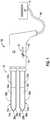
- Fig.1shows an ablation system 10 that includes an antenna assembly 12 coupled to an output 15 of an electrosurgical generator 14 via a flexible coaxial cable 16.
- the generator 14is adapted to provide microwave energy at an operational frequency from about 300 MHz to about 6000 MHz, although other suitable frequencies (e.g., radio frequency) are also contemplated.
- the antenna assembly 12includes a pair of antennas 15a and 15b disposed substantially parallel to each other, for example, spaced about 5 millimeters (mm) apart.
- Antennas 15a, 15bare inserted directly into tissue or placed into the body during surgery by a clinician, or positioned in the body by other suitable methods.
- Antennas 15a, 15binclude radiating portions 18a, 18b, respectively, that are connected by respective feedlines 20a, 20b, to the cable 16. More specifically, the antenna assembly 12 is coupled to the cable 16 through a connection hub or handle 22 that is connected in fluid communication with sheaths 38a, 38b that enclose radiating portions 18a, 18b and feedlines 20a, 20b, respectively. As shown schematically in Fig.
- a control circuit 100 disposed within handle 22is configured to connect to output 15 of generator 14 and equally split energy supplied by generator 14 between a pair of channels 151a and 151b in a predetermined phase relationship to drive antennas 15a and 15b, respectively.
- Channels 151a, 151belectrically connect to a variable phase shifter 180 disposed within control circuit 100.
- Phase shifter 180is operably coupled to a user-accessible switching mechanism 21 disposed on the handle 22 that allows the user to selectively shift the phase of either channel 151a and/or 151b relative to the other channel to achieve a desired phase relationship (e.g., in-phase, out-of-phase) between antennas 15a, 15b, as discussed in detail below.
- a desired phase relationshipe.g., in-phase, out-of-phase
- switching mechanism 21includes a slide button 23 that is disposed about the exterior of the handle 22 and is configured to slide within a groove 25 defined at least partially through the handle 22 to control the phase relationship between channels 151a, 151b in mutual cooperation with variable phase shifter 180.
- variable phase shifter 180may include an electrical transmission line such as microstrip (not shown) that is suitably positioned within handle 22 relative to groove 25 to be mechanically engaged by slide button 23 for controlling the variable phase shifter 180.
- switching mechanism 21may, in lieu of slide button 23, include any suitable switching mechanism such as, for example without limitation, a toggle switch, a push button, a dial, a potentiometer, an air-gap switch, a paddle actuator, a lever, or the like.
- Channels 151a and/or 151bare electrically connected, via corresponding outputs 101a and 101b of variable phase shifter 180, to feedlines 20a and 20b, respectively, to supply electrosurgical energy to radiating portions 18a, 18b for application to tissue.
- the sheaths 38a, 38benclose radiating portions 18a, 18b, respectively, and feedlines 20a, 20b to form a chamber (not shown) that allows one or more materials such as, for example, fluid, gas, coolant, chemicals, saline, water, powdered solids, or any combination thereof, to circulate within and/or occupy space within the chamber.
- handle 22may be coupled to a suitable supply pump (not shown) adapted to supply fluid or coolant to the chamber.
- antenna assembly 12may be embodied as, for example without limitation, a radiofrequency monopolar and/or bipolar electrode assembly, an ultrasound transducer, laser fiber, a direct current (DC) heating element, or the like.
- Antenna assembly 12also includes a tip 48a, 48b disposed at a distal end of each radiating portion 18a, 18b, respectively.
- Each tip 48a, 48bhas a respective tapered end 24a, 24b that terminates, in some embodiments, at a respective pointed end 26a, 26b to allow for insertion into tissue with minimal resistance.
- tips 48a, 48bmay be rounded or flat. Tips 48a, 48b may be formed from a variety of heat-resistant materials suitable for penetrating tissue, such as metals (e.g., stainless steel) and various thermoplastic materials, such as poletherimide, and polyamide thermoplastic resins.
- the antenna assembly 12is a microwave antenna configured to allow direct insertion or penetration into tissue of a patient.
- the antenna assembly 12may be axially rigid to allow for tissue penetration.
- the antenna assembly 12is sufficiently small in diameter to be minimally invasive of the body, which may reduce the preparation of the patient as might be required for more invasive penetration of the body.
- the antenna assembly 12is inserted directly into tissue, inserted through a lumen (e.g., a vein, a needle, a catheter), placed into the body during surgery by a clinician, or positioned in the body by other suitable methods.
- a lumene.g., a vein, a needle, a catheter
- Fig. 2Bis a schematic diagram of control circuit 100, according to one embodiment of the present disclosure.
- Control circuit 100includes a power splitter 150 that is electrically connected via a transmission line 140 to the output 15 of generator 14.
- the power splitter 150may be implemented by any suitable power divider that provides an equal or unequal power split at its output ports while substantially maintaining a predetermined phase relationship.
- the power splitter 150may be implemented using a 2-way power divider that provides an equal power split at its output ports while maintaining a phase difference of +/-90 degrees (e.g., via a 90 degree power divider IC).
- Power splitter 150receives, as an input signal, electrosurgical output from the generator 14.
- the power splitter 150splits the input signal received from generator 14 equally between a pair of channels 151a and 151b at a phase difference of 90 degrees.
- Channels 151a and 151bpass through a pair of corresponding directional couplers 160a and 160b that are configured to couple reflected power on channels 151a, 151b to corresponding rectifiers 170a, 170b (e.g., microwave to DC rectifiers) for purposes of reflected power monitoring.
- Transmission lines 175a and 175belectrically connect rectifiers 170a, 170b, respectively, to generator 14 by way of cable 16 such that rectifiers 170a, 170b may communicate data to generator 14 for processing.
- the line and load impedancesshould match. If the line and load impedances do not match (e.g., an impedance mismatch) a reflected wave may be created that can generate a standing wave, which contributes to a power loss associated with the impedance mismatch.
- the generator 14is configured to control energy output to the antenna assembly 12 based on an outer feedback loop that monitors a reflectance parameter (e.g., received from rectifier(s) 175a and/or 175b) such as a mismatch detected between the load impedance and the line impedance.
- a reflectance parametere.g., received from rectifier(s) 175a and/or 175b
- Such an impedance mismatchmay cause a portion of the power, so called “reflected power,” from the generator 14 to not reach the tissue site and cause the power delivered, the so called “forward power", to vary in an irregular or inconsistent manner.
- It is possible to determine ablation completeness based on the impedance mismatchby measuring and analyzing the reflected and forward power.
- the generator 14measures energy delivery properties, namely the reflected power, to determine ablation completeness.
- the generator 14terminates or adjusts energy output and alerts the user of the ablation completeness via an audible and/or visual indicator (not shown) disposed on the antenna assembly 12 and/or the generator 14.
- Channels 151a, 151bpass through variable phase shifter 180 that, as described above, is user-controlled via the switching mechanism 23 disposed on handle 22. At this juncture (e.g., prior to passing through variable phase shifter 180), channels 151a, 151b are 90 degrees out-of-phase, as discussed hereinabove.
- a desired effect on tissue between the antennas 15a, 15bis produced.
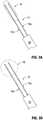
- a 180 degree out-of-phase relationship between antennas 15a, 15bproduces a desired effect on tissue. More specifically, the out-of-phase relationship between antennas 15a, 15b generates proximal energy propagation therebetween to produce the elongated ablation pattern "A" suitable for planar tissue coagulation.
- an in-phase relationship between antennas 15a, 15bproduces a desired effect on tissue. More specifically, the in-phase relationship between antennas 15a, 15b substantially eliminates proximal energy propagation therebetween to produce a generally spherical ablation pattern "B" suitable for focal tissue ablation proximate radiating portions 18a, 18b of antennas 15a, 15b, respectively.
- variable phase shifter 180is user-controlled via switching mechanism 23 disposed on handle 22 such that channels 151a, 151b may be configured in various phase relationships relative to one another in accordance with a desired tissue ablation pattern or geometry, as described above.
- phase shifter 180may include an out-of-phase configuration wherein the phase of one of channels 151a or 151b is shifted 90 degrees such that channels 151a, 151b are changed from being 90 degrees out-of-phase (via the power splitter 150) to being 180 degrees out-of-phase.
- the 180 degree out-of-phase relationship between channels 151a, 151bproduces a long thin ablation pattern "A" that is ideal for a tissue resection procedure. In this manner, when channels 151a, 151b are 180 degrees out-of-phase, antenna assembly 12 is said to be operating in a "tissue resection mode".
- Phase shifter 180may also include, by way of example, an in-phase configuration wherein the phase of one of channels 151a or 151b is shifted 90 degrees such that channels 151a, 151b are changed from being 90 degrees out-of-phase (via the power splitter 150) to being in-phase or having a 0 degree phase difference.
- the in-phase relationship between channels 151a, 151bproduces a generally spherical ablation pattern "B" with a relatively larger radius that is ideal for a tissue ablation procedure. In this manner, when channels 151a, 151b are in-phase, antenna assembly 12 is said to be operating in a "tissue ablation mode".
- Fig. 4is a flowchart illustrating a method for providing energy to a target tissue, according to an embodiment of the present disclosure.
- antennas 15a, 15b of antenna assembly 12are positioned relative to the target tissue.
- the antenna assembly 12is inserted directly into tissue, inserted through a lumen (e.g., a vein, needle, or catheter), placed into the body during surgery by a clinician, or positioned in the body by other suitable methods.
- a lumene.g., a vein, needle, or catheter
- microwave poweris supplied by generator 14 to the antenna assembly 12 and is split equally between a pair of channels 151a, 151b by the power splitter 150 in a predetermined phase relationship (e.g., +/- 90 degrees).
- the phase relationship between channels 151a, 151bis selectively adjusted through use of a user-controlled variable phase shifter 180 in accordance with a desired ablation pattern (e.g., pattern "A” or pattern "B"), a desired phase configuration (e.g., in-phase, out-of-phase), a desired phase relationship (e.g., +/- 0 degrees, +/- 90 degrees, +/-180 degrees, etc.), and/or a desired mode of operation of antenna assembly 12 (e.g., tissue resection mode, tissue ablation mode).
- a desired ablation patterne.g., pattern "A" or pattern "B”
- a desired phase configuratione.g., in-phase, out-of-phase
- a desired phase relationshipe.g., +/- 0 degrees, +/- 90 degrees, +/-180 degrees, etc.
- a desired mode of operation of antenna assembly 12e.g., tissue resection mode, tissue ablation mode
- step 440the microwave power is selectively transmitted from channels 151a, 151b to radiating portions 18a, 18b, respectively, via corresponding outputs 101a, 101b of the variable phase shifter 180.
- step 450microwave energy from radiating portions 18a, 18b is applied to the target tissue to achieve the desired ablation pattern or geometry.
- the method for providing energy to a target tissueincludes the step of monitoring reflected power detected on channels 151a, 151b, as described hereinabove in connection with Fig. 2B , and controlling energy supplied to the antenna assembly 12 by generator 14 based on the detected reflected power.
Landscapes
- Health & Medical Sciences (AREA)
- Life Sciences & Earth Sciences (AREA)
- Biomedical Technology (AREA)
- Engineering & Computer Science (AREA)
- Surgery (AREA)
- Animal Behavior & Ethology (AREA)
- General Health & Medical Sciences (AREA)
- Nuclear Medicine, Radiotherapy & Molecular Imaging (AREA)
- Veterinary Medicine (AREA)
- Public Health (AREA)
- Heart & Thoracic Surgery (AREA)
- Molecular Biology (AREA)
- Physics & Mathematics (AREA)
- Medical Informatics (AREA)
- Otolaryngology (AREA)
- Electromagnetism (AREA)
- Pathology (AREA)
- Radiology & Medical Imaging (AREA)
- Surgical Instruments (AREA)
Description
- The present disclosure relates to apparatus for providing energy to tissue and, more particularly, to devices and electromagnetic radiation delivery procedures utilizing ablation probes to control the delivery of electromagnetic radiation to tissue.
- Treatment of certain diseases requires destruction of malignant tumors. Electromagnetic radiation can be used to heat and destroy tumor cells. Treatment may involve inserting ablation probes into tissues where cancerous tumors have been identified. Once the probes are positioned, electromagnetic energy is passed through the probes into surrounding tissue.
- In the treatment of diseases such as cancer, certain types of cancer cells have been found to denature at elevated temperatures that are slightly lower than temperatures normally injurious to healthy cells. Known treatment methods, such as hyperthermia therapy, use electromagnetic radiation to heat diseased cells to temperatures above 41° C while maintaining adjacent healthy cells below the temperature at which irreversible cell destruction occurs. These methods involve applying electromagnetic radiation to heat, ablate and/or coagulate tissue. Microwave energy is sometimes utilized to perform these methods. Other procedures utilizing electromagnetic radiation to heat tissue also include coagulation, cutting and/or ablation of tissue.
- Electrosurgical devices utilizing electromagnetic radiation have been developed for a variety of uses and applications. A number of devices are available that can be used to provide high bursts of energy for short periods of time to achieve cutting and coagulative effects on various tissues. There are a number of different types of apparatus that can be used to perform ablation procedures. Typically, microwave apparatus for use in ablation procedures include a microwave generator, which functions as an energy source, and a microwave surgical instrument having an antenna assembly for directing the energy to the target tissue. The microwave generator and surgical instrument are typically operatively coupled by a cable assembly having a plurality of conductors for transmitting microwave energy from the generator to the instrument, and for communicating control, feedback and identification signals between the instrument and the generator.
- Microwave energy is typically applied via antenna assemblies that can penetrate tissue. Several types of antenna assemblies are known, such as monopole and dipole antenna assemblies. In monopole and dipole antenna assemblies, microwave energy generally radiates perpendicularly away from the axis of the conductor. A monopole antenna assembly includes a single, elongated conductor that transmits microwave energy. A typical dipole antenna assembly has two elongated conductors, which are linearly aligned and positioned end-to-end relative to one another with an electrical insulator placed therebetween. Each conductor may be about 1/4 of the length of a wavelength of the microwave energy, making the aggregate length of the two conductors about 1/2 of the wavelength of the supplied microwave energy. During certain procedures, it can be difficult to assess the extent to which the microwave energy will radiate into the surrounding tissue, making it difficult to determine the area or volume of surrounding tissue that will be ablated.
EP 2 149 343 discloses a tissue ablation system comprising a plurality of microwave antennas and a power splitter for equally splitting power generated by a power generator to be distributed to the plurality of antennas in equal amounts. A controller is configured to monitor a phase of each channel dedicated to the plurality of microwave antennas and to adjust the phase of the signal in each channel with respect to the other channels to a predetermined phase relationship, such as +/- 45 degrees, +/- 10 degrees, in phase, or 180 degrees out of phase.WO 2008/068485 discloses a surgical ablation unit comprising forward and reverse directional couplers for compensating for varying impedances over an area of tissue to be treated to finely control the level of energy radiated into the tissue. PIN diodes may be used to control a phase of a plurality of radiating patches with respect to each other. By combining adjustment of power levels and phase differences applied to the individual radiating elements, uniform energy can be applied to the surface of the skin, even when changes in the structure of the tissue may require different amounts of energy or different matching conditions. Therefore, the radiating elements may be individually controllable to adapt to variability in tissue structure over a treatment area.WO 1993/009845 discloses a microwave hypothermia system including two applicators for distributing electromagnetic energy into tissue, including a power splitter for dividing power from a power source, and a phase shifter configured to shift relative phases of the energy applied to the two applicators. The phase shaft can be controlled in response to a control signal from a phase shift controller to shift the phase in conjunction with a source power level or frequency.US 6,208,903 discloses a microwave applicator including two applicators, a power splitter, and a variable phase shifter controlled by a difference signal between a sensed phase and amplitude and a reference phase and amplitude signal for each applicator in order to achieve a desired pre-set phase difference.WO 2009/075904 discloses a microwave applicator comprising a plurality of slot antennas. Spacing, alignment, and phase relationship between the antennas may be altered by one skilled in the art depending on the desired clinical result.US 5,767, 756 discloses a power splitter for obtaining output signals having a phase difference of 90 degrees.WO2008/008545 andEP1244390 disclose further documents relevant for the present invention.- An electrosurgical ablation system according to independent claim 1 defines the present invention. The electrosurgical ablation system includes an energy source adapted to supply energy to an energy delivery device. The energy delivery device includes a handle assembly configured to couple a pair of antennas extending from a distal end thereof to the energy source for application of energy to tissue. A power splitting device is operatively associated with the handle assembly and has an input adapted to connect to the energy source and a pair of output channels operably coupled to the respective pair of antennas. A phase shifter is operatively associated with the handle assembly and is operably coupled to the pair of output channels. The phase shifter is configured to selectively shift a phase relationship between the pair of output channels.
- An exemplary method of providing energy to a target tissue includes the steps of positioning an energy delivery device relative to a target tissue site and equally dividing energy supplied to the energy delivery device from an energy source between a pair of channels in a predetermined phase relationship. The method also includes selectively shifting the phase relationship between the pair of channels and applying the equally divided energy to the target tissue in the selectively adjusted phase relationship.
- An exemplary method of providing energy to a target tissue includes the steps of positioning a microwave antenna assembly relative to a target tissue site and equally dividing energy supplied to the microwave antenna assembly from an energy source between a pair of channels in a predetermined phase relationship. The method also includes the step of selectively shifting the phase of at least one channel +/- 90 degrees to shift the phase relationship between the channels to one of an in-phase configuration and an out-of-phase configuration based on a desired tissue ablation geometry. The method also includes the step of applying the equally divided energy from the pair of channels to a corresponding pair of antennas for application to target tissue.
Fig. 1 is a schematic diagram of an electrosurgical system for treating tissue, according to an embodiment of the present disclosure;Fig. 2A is a partial schematic diagram of the electrosurgical system ofFig. 1 showing a control circuit in accordance with an embodiment of the present disclosure;Fig. 2B is a schematic diagram of the control circuit ofFig. 2A ;Figs. 3A and 3B are schematic diagrams of antennas assemblies illustrating tissue ablation geometries in accordance with various embodiments of the present disclosure; andFig. 4 is a block diagram illustrating a method for treating tissue, according to the present disclosure.- The invention is defined by the appended independent claim 1. Preferred embodiments are defined in the dependent claims. Hereinafter, embodiments of the presently disclosed tissue ablation systems are described with reference to the accompanying drawings. Like reference numerals may refer to similar or identical elements throughout the description of the figures. As used herein, the term "microwave" generally refers to electromagnetic waves in the frequency range of 300 megahertz (MHz) (3 x 10⁸ cycles/second) to 300 gigahertz (GHz) (3 x 10¹¹ cycles/second). As used herein, the phrase "transmission line" generally refers to any transmission medium that can be used for the propagation of signals from one point to another.
- Various embodiments of the present disclosure provide electrosurgical systems for treating tissue. Embodiments may be implemented using electromagnetic radiation at microwave frequencies or at other frequencies. Electrosurgical systems for treating tissue, according to various embodiments of the present disclosure, deliver microwave power to an electrosurgical device. An electrosurgical device, such as an ablation antenna, for implementing embodiments of the present disclosure may be inserted directly into tissue, inserted through a lumen, such as a vein, needle or catheter, placed into the body during surgery by a clinician, or positioned in the body by other suitable methods known in the art.
- The present disclosure relates generally to an ablation system that equally splits microwave power between a pair of antennas of an ablation device at a predetermined phase relationship. The phase relationship is user-selected and is based on an ablation procedure being performed and/or on a desired ablation pattern or geometry. As discussed in further detail below, by controlling the phase of ablation antennas with respect to each other, according to embodiments of the present disclosure, a desired effect on tissue between the antennas is produced.
Fig.1 shows anablation system 10 that includes anantenna assembly 12 coupled to anoutput 15 of anelectrosurgical generator 14 via a flexiblecoaxial cable 16. Thegenerator 14 is adapted to provide microwave energy at an operational frequency from about 300 MHz to about 6000 MHz, although other suitable frequencies (e.g., radio frequency) are also contemplated.- In the illustrated embodiment, the
antenna assembly 12 includes a pair ofantennas Antennas Antennas portions respective feedlines cable 16. More specifically, theantenna assembly 12 is coupled to thecable 16 through a connection hub or handle 22 that is connected in fluid communication withsheaths portions feedlines Fig. 2A and as discussed in further detail below with respect toFig. 2B , acontrol circuit 100 disposed withinhandle 22 is configured to connect tooutput 15 ofgenerator 14 and equally split energy supplied bygenerator 14 between a pair ofchannels antennas Channels variable phase shifter 180 disposed withincontrol circuit 100.Phase shifter 180 is operably coupled to a user-accessible switching mechanism 21 disposed on thehandle 22 that allows the user to selectively shift the phase of eitherchannel 151a and/or 151b relative to the other channel to achieve a desired phase relationship (e.g., in-phase, out-of-phase) betweenantennas - As shown in the illustrated embodiment of
Fig. 1 ,switching mechanism 21 includes aslide button 23 that is disposed about the exterior of thehandle 22 and is configured to slide within agroove 25 defined at least partially through thehandle 22 to control the phase relationship betweenchannels variable phase shifter 180. More specifically,variable phase shifter 180 may include an electrical transmission line such as microstrip (not shown) that is suitably positioned withinhandle 22 relative to groove 25 to be mechanically engaged byslide button 23 for controlling thevariable phase shifter 180. For purposes of connecting to and controllingvariable phase shifter 180 from the exterior ofhandle 22,switching mechanism 21 may, in lieu ofslide button 23, include any suitable switching mechanism such as, for example without limitation, a toggle switch, a push button, a dial, a potentiometer, an air-gap switch, a paddle actuator, a lever, or the like. Channels 151a and/or 151b are electrically connected, via correspondingoutputs variable phase shifter 180, to feedlines 20a and 20b, respectively, to supply electrosurgical energy to radiatingportions sheaths portions feedlines antenna assembly 12 may be embodied as, for example without limitation, a radiofrequency monopolar and/or bipolar electrode assembly, an ultrasound transducer, laser fiber, a direct current (DC) heating element, or the like.Antenna assembly 12 also includes atip portion tip tapered end pointed end portions tips Tips - In embodiments, the
antenna assembly 12 is a microwave antenna configured to allow direct insertion or penetration into tissue of a patient. Theantenna assembly 12 may be axially rigid to allow for tissue penetration. Theantenna assembly 12 is sufficiently small in diameter to be minimally invasive of the body, which may reduce the preparation of the patient as might be required for more invasive penetration of the body. Theantenna assembly 12 is inserted directly into tissue, inserted through a lumen (e.g., a vein, a needle, a catheter), placed into the body during surgery by a clinician, or positioned in the body by other suitable methods. Fig. 2B is a schematic diagram ofcontrol circuit 100, according to one embodiment of the present disclosure.Control circuit 100 includes apower splitter 150 that is electrically connected via atransmission line 140 to theoutput 15 ofgenerator 14. Thepower splitter 150 may be implemented by any suitable power divider that provides an equal or unequal power split at its output ports while substantially maintaining a predetermined phase relationship. For example, thepower splitter 150 may be implemented using a 2-way power divider that provides an equal power split at its output ports while maintaining a phase difference of +/-90 degrees (e.g., via a 90 degree power divider IC).Power splitter 150 receives, as an input signal, electrosurgical output from thegenerator 14. Thepower splitter 150 splits the input signal received fromgenerator 14 equally between a pair ofchannels Channels directional couplers channels corresponding rectifiers Transmission lines rectifiers generator 14 by way ofcable 16 such thatrectifiers generator 14 for processing.- When coupling electromagnetic radiation such as microwaves from a source to an applicator, in order to maximize the amount of energy transferred from the source (e.g., generator 14) to the load (e.g.,
antennas generator 14 is configured to control energy output to theantenna assembly 12 based on an outer feedback loop that monitors a reflectance parameter (e.g., received from rectifier(s) 175a and/or 175b) such as a mismatch detected between the load impedance and the line impedance. Such an impedance mismatch may cause a portion of the power, so called "reflected power," from thegenerator 14 to not reach the tissue site and cause the power delivered, the so called "forward power", to vary in an irregular or inconsistent manner. It is possible to determine ablation completeness based on the impedance mismatch by measuring and analyzing the reflected and forward power. In particular, thegenerator 14 measures energy delivery properties, namely the reflected power, to determine ablation completeness. When the reflected power detected reaches a particular or predetermined level indicative of ablation completeness or reaches a particular or predetermined rate of change over time indicative of ablation completeness, thegenerator 14 terminates or adjusts energy output and alerts the user of the ablation completeness via an audible and/or visual indicator (not shown) disposed on theantenna assembly 12 and/or thegenerator 14. Channels variable phase shifter 180 that, as described above, is user-controlled via theswitching mechanism 23 disposed onhandle 22. At this juncture (e.g., prior to passing through variable phase shifter 180),channels - Referring for a moment to
Figs. 3A and 3B , by controlling the phase ofantennas antennas Fig. 3A , a 180 degree out-of-phase relationship betweenantennas antennas Fig. 3B , an in-phase relationship betweenantennas antennas proximate radiating portions antennas - As mentioned above,
variable phase shifter 180 is user-controlled via switchingmechanism 23 disposed onhandle 22 such thatchannels phase shifter 180 may include an out-of-phase configuration wherein the phase of one ofchannels channels channels channels antenna assembly 12 is said to be operating in a "tissue resection mode". Phase shifter 180 may also include, by way of example, an in-phase configuration wherein the phase of one ofchannels channels channels channels antenna assembly 12 is said to be operating in a "tissue ablation mode".Fig. 4 is a flowchart illustrating a method for providing energy to a target tissue, according to an embodiment of the present disclosure. Referring initially to step 410,antennas antenna assembly 12 are positioned relative to the target tissue. Theantenna assembly 12 is inserted directly into tissue, inserted through a lumen (e.g., a vein, needle, or catheter), placed into the body during surgery by a clinician, or positioned in the body by other suitable methods.- In
step 420, microwave power is supplied bygenerator 14 to theantenna assembly 12 and is split equally between a pair ofchannels power splitter 150 in a predetermined phase relationship (e.g., +/- 90 degrees). - In
step 430, the phase relationship betweenchannels variable phase shifter 180 in accordance with a desired ablation pattern (e.g., pattern "A" or pattern "B"), a desired phase configuration (e.g., in-phase, out-of-phase), a desired phase relationship (e.g., +/- 0 degrees, +/- 90 degrees, +/-180 degrees, etc.), and/or a desired mode of operation of antenna assembly 12 (e.g., tissue resection mode, tissue ablation mode). - In
step 440, the microwave power is selectively transmitted fromchannels portions outputs variable phase shifter 180. - In
step 450, microwave energy from radiatingportions - In some embodiments, the method for providing energy to a target tissue includes the step of monitoring reflected power detected on
channels Fig. 2B , and controlling energy supplied to theantenna assembly 12 bygenerator 14 based on the detected reflected power.
Claims (12)
- An electrosurgical ablation system (10), comprising:an energy source (14) adapted to supply energy to an energy delivery device, device;an energy delivery device including a handle assembly (22) coupled to a pair of antenna probes (15a, 15b) extending from a distal end thereof to the energy source (14) which probes being configured for insertion into tissue for application of energy to the tissue;a power splitting device (150) operatively associated with the handle assembly (22) and having an input adapted to connect to the energy source (14) and a pair of output channels (151a, 151b) operably coupled to the respective pair of antenna probes (15a, 15b); anda phase shifter (180) operatively associated with the handle assembly (22) and operably coupled to the pair of output channels (151a, 151b), the phase shifter configured to selectively shift a phase relationship between the pair of output channels (151a, 151b);further comprising:a switch assembly (21) disposed on the handle assembly (22), operably coupled to the phase shifter (180), and configured to be operated by a user to selectively shift a phase of one of the channels (151a, 151b) relative to the other of the channels (151a, 151b) in order to modify the ablation pattern or geometry in the tissue,and further comprising at least one rectifier disposed in operative communication with the energy source (14) to monitor reflected power detected on the pair of output channels (151a, 151b), wherein the energy source (14) controls the energy supplied to the energy delivery device based on the detected reflected power.
- An electrosurgical ablation system according to claim 1, wherein the energy source (14) is a microwave generator adapted to supply microwave energy to the energy delivery device.
- An electrosurgical ablation system according to claim 1, wherein the switch assembly (21) includes a slide switch (23) accessible from an exterior of the handle assembly (22) and configured to slide within a groove (25) defined within the handle assembly (22) to control the phase shifter (180).
- An electrosurgical ablation system according to claim 1, wherein the phase shifter (180) is selectively controlled to generate a phase difference of +/-180 degrees between the pair of antenna probes (15a,15b).
- An electrosurgical ablation system according to claim 4, wherein the energy delivery device is configured to operate in a tissue resection mode when the phase difference between the pair of antenna probes (15a,15b) is +/-180 degrees.
- An electrosurgical ablation system according to claim 1, wherein the phase shifter (180) is configured to be selectively controlled to generate an in-phase relationship between the pair of antenna probes (15a,15b).
- An electrosurgical ablation system according to claim 6, wherein the energy delivery device is configured to operate in a tissue ablation mode when an in-phase relationship exists between the pair of antenna probes (15a,15b).
- An electrosurgical ablation system according to claim 1, wherein the phase shifter (180) is configured to be selectively controlled to generate an in-phase relationship between the pair of antenna probes (15a, 15b) to produce a generally spherical ablation geometry proximate a radiating portion of each of the pair of antenna probes (15a, 15b).
- An electrosurgical ablation system according to claim 1, wherein the phase shifter (180) is configured to be selectively controlled to generate an out-of-phase relationship between the pair of antenna probes (15a, 15b) to produce a generally elongated ablation geometry proximate a radiating portion of each of the pair of antenna probes (15a,15b).
- An electrosurgical ablation system according to claim 1, wherein the pair of antenna probes (15a, 15b) are substantially parallel to one another.
- An electrosurgical ablation system according to claim 1, wherein the power splitting device (150) is a 90 degree power divider.
- An electrosurgical ablation system according to claim 1, wherein the power splitting device (150) generates a substantially equal power split between the pair of output channels (151a, 151b) while maintaining a phase difference of +/-90 degrees between the pair of output channels (151a, 151b).
Applications Claiming Priority (1)
| Application Number | Priority Date | Filing Date | Title |
|---|---|---|---|
| US12/837,820US8974449B2 (en) | 2010-07-16 | 2010-07-16 | Dual antenna assembly with user-controlled phase shifting |
Publications (2)
| Publication Number | Publication Date |
|---|---|
| EP2407205A1 EP2407205A1 (en) | 2012-01-18 |
| EP2407205B1true EP2407205B1 (en) | 2020-02-26 |
Family
ID=44653948
Family Applications (1)
| Application Number | Title | Priority Date | Filing Date |
|---|---|---|---|
| EP11005827.8AActiveEP2407205B1 (en) | 2010-07-16 | 2011-07-15 | Dual antenna assembly with user-controlled phase shifting |
Country Status (3)
| Country | Link |
|---|---|
| US (3) | US8974449B2 (en) |
| EP (1) | EP2407205B1 (en) |
| JP (1) | JP6122239B2 (en) |
Families Citing this family (12)
| Publication number | Priority date | Publication date | Assignee | Title |
|---|---|---|---|---|
| US8394092B2 (en) | 2009-11-17 | 2013-03-12 | Vivant Medical, Inc. | Electromagnetic energy delivery devices including an energy applicator array and electrosurgical systems including same |
| US8974449B2 (en) | 2010-07-16 | 2015-03-10 | Covidien Lp | Dual antenna assembly with user-controlled phase shifting |
| US9055957B2 (en) | 2010-12-23 | 2015-06-16 | Covidien Lp | Microwave field-detecting needle assemblies, methods of manufacturing same, methods of adjusting an ablation field radiating into tissue using same, and systems including same |
| US9770294B2 (en) | 2011-01-05 | 2017-09-26 | Covidien Lp | Energy-delivery devices with flexible fluid-cooled shaft, inflow/outflow junctions suitable for use with same, and systems including same |
| US9028476B2 (en) | 2011-02-03 | 2015-05-12 | Covidien Lp | Dual antenna microwave resection and ablation device, system and method of use |
| US10335230B2 (en) | 2011-03-09 | 2019-07-02 | Covidien Lp | Systems for thermal-feedback-controlled rate of fluid flow to fluid-cooled antenna assembly and methods of directing energy to tissue using same |
| US10363084B2 (en) | 2015-04-01 | 2019-07-30 | Covidien Lp | Interdigitation of waveforms for dual-output electrosurgical generators |
| WO2016168435A1 (en) | 2015-04-14 | 2016-10-20 | Crysanthe, Inc. | System and method for selective treatment of skin and subcutaneous fat using a single frequency dual mode radio frequency antenna device |
| CN108289701A (en)* | 2015-11-27 | 2018-07-17 | 奥林巴斯株式会社 | energy treatment apparatus |
| CN108882963B (en)* | 2016-03-22 | 2023-01-03 | 微立方有限责任公司 | Methods and apparatus for energy delivery and treatment |
| GB2559604A (en)* | 2017-02-13 | 2018-08-15 | Creo Medical Ltd | Microwave energy transfer component for electrosurgical apparatus |
| US11103308B2 (en)* | 2017-12-11 | 2021-08-31 | Covidien Lp | Reusable transmission network for dividing energy and monitoring signals between surgical devices |
Citations (4)
| Publication number | Priority date | Publication date | Assignee | Title |
|---|---|---|---|---|
| EP1244390A2 (en)* | 1999-12-30 | 2002-10-02 | Pearl Technology Holdings, LLC | Face-lifting device |
| USRE38143E1 (en)* | 1995-10-27 | 2003-06-17 | Dornier Medical Systems, Inc. | Organ separation for thermal therapy |
| WO2008008545A2 (en)* | 2006-07-14 | 2008-01-17 | Micrablate | Energy delivery systems and uses thereof |
| WO2011063061A2 (en)* | 2009-11-17 | 2011-05-26 | Bsd Medical Corporation | Microwave coagulation applicator and system |
Family Cites Families (129)
| Publication number | Priority date | Publication date | Assignee | Title |
|---|---|---|---|---|
| DE390937C (en) | 1922-10-13 | 1924-03-03 | Adolf Erb | Device for internal heating of furnace furnaces for hardening, tempering, annealing, quenching and melting |
| DE1099658B (en) | 1959-04-29 | 1961-02-16 | Siemens Reiniger Werke Ag | Automatic switch-on device for high-frequency surgical devices |
| FR1275415A (en) | 1960-09-26 | 1961-11-10 | Device for detecting disturbances for electrical installations, in particular electrosurgery | |
| DE1139927B (en) | 1961-01-03 | 1962-11-22 | Friedrich Laber | High-frequency surgical device |
| DE1149832C2 (en) | 1961-02-25 | 1977-10-13 | Siemens AG, 1000 Berlin und 8000 München | HIGH FREQUENCY SURGICAL EQUIPMENT |
| FR1347865A (en) | 1962-11-22 | 1964-01-04 | Improvements to diathermo-coagulation devices | |
| DE1439302B2 (en) | 1963-10-26 | 1971-05-19 | Siemens AG, 1000 Berlin u 8000 München | High frequency surgical device |
| SU401367A1 (en) | 1971-10-05 | 1973-10-12 | Тернопольский государственный медицинский институт | BIAKTIVNYE ELECTRO SURGICAL INSTRUMENT |
| FR2235669A1 (en) | 1973-07-07 | 1975-01-31 | Lunacek Boris | Gynaecological sterilisation instrument - has hollow electrode protruding from the end of a curved ended tube |
| GB1480736A (en) | 1973-08-23 | 1977-07-20 | Matburn Ltd | Electrodiathermy apparatus |
| FR2251864A1 (en) | 1973-11-21 | 1975-06-13 | Termiflex Corp | Portable input and output unit for connection to a data processor - is basically a calculator with transmitter and receiver |
| DE2407559C3 (en) | 1974-02-16 | 1982-01-21 | Dornier System Gmbh, 7990 Friedrichshafen | Heat probe |
| DE2415263A1 (en) | 1974-03-29 | 1975-10-02 | Aesculap Werke Ag | Surgical H.F. coagulation probe has electrode tongs - with exposed ends of insulated conductors forming tong-jaws |
| DE2429021C2 (en) | 1974-06-18 | 1983-12-08 | Erbe Elektromedizin GmbH, 7400 Tübingen | Remote switching device for an HF surgical device |
| FR2276027A1 (en) | 1974-06-25 | 1976-01-23 | Medical Plastics Inc | Plate electrode with connector - is clamped between connector jaws held by releasable locking device |
| DE2460481A1 (en) | 1974-12-20 | 1976-06-24 | Delma Elektro Med App | Electrode grip for remote HF surgical instrument switching - has shaped insulated piece with contact ring of sterilizable (silicon) rubber |
| US4237887A (en) | 1975-01-23 | 1980-12-09 | Valleylab, Inc. | Electrosurgical device |
| DE2504280C3 (en) | 1975-02-01 | 1980-08-28 | Hans Heinrich Prof. Dr. 8035 Gauting Meinke | Device for cutting and / or coagulating human tissue with high frequency current |
| CA1064581A (en) | 1975-06-02 | 1979-10-16 | Stephen W. Andrews | Pulse control circuit and method for electrosurgical units |
| FR2315286A2 (en) | 1975-06-26 | 1977-01-21 | Lamidey Marcel | H.F. blood coagulating dissecting forceps - with adjustable stops to vary clamping space and circuit making contacts |
| DE2540968C2 (en) | 1975-09-13 | 1982-12-30 | Erbe Elektromedizin GmbH, 7400 Tübingen | Device for switching on the coagulation current of a bipolar coagulation forceps |
| FR2390968A1 (en) | 1977-05-16 | 1978-12-15 | Skovajsa Joseph | Local acupuncture treatment appts. - has oblong head with end aperture and contains laser diode unit (NL 20.11.78) |
| SU727201A2 (en) | 1977-11-02 | 1980-04-15 | Киевский Научно-Исследовательский Институт Нейрохирургии | Electric surgical apparatus |
| DE2803275C3 (en) | 1978-01-26 | 1980-09-25 | Aesculap-Werke Ag Vormals Jetter & Scheerer, 7200 Tuttlingen | Remote switching device for switching a monopolar HF surgical device |
| DE2823291A1 (en) | 1978-05-27 | 1979-11-29 | Rainer Ing Grad Koch | Coagulation instrument automatic HF switching circuit - has first lead to potentiometer and second to transistor base |
| US4448198A (en)* | 1979-06-19 | 1984-05-15 | Bsd Medical Corporation | Invasive hyperthermia apparatus and method |
| DE2946728A1 (en) | 1979-11-20 | 1981-05-27 | Erbe Elektromedizin GmbH & Co KG, 7400 Tübingen | HF surgical appts. for use with endoscope - provides cutting or coagulation current at preset intervals and of selected duration |
| USD263020S (en) | 1980-01-22 | 1982-02-16 | Rau Iii David M | Retractable knife |
| JPS5778844A (en) | 1980-11-04 | 1982-05-17 | Kogyo Gijutsuin | Lasre knife |
| DE3045996A1 (en) | 1980-12-05 | 1982-07-08 | Medic Eschmann Handelsgesellschaft für medizinische Instrumente mbH, 2000 Hamburg | Electro-surgical scalpel instrument - has power supply remotely controlled by surgeon |
| FR2502935B1 (en) | 1981-03-31 | 1985-10-04 | Dolley Roger | METHOD AND DEVICE FOR CONTROLLING THE COAGULATION OF TISSUES USING A HIGH FREQUENCY CURRENT |
| DE3120102A1 (en) | 1981-05-20 | 1982-12-09 | F.L. Fischer GmbH & Co, 7800 Freiburg | ARRANGEMENT FOR HIGH-FREQUENCY COAGULATION OF EGG WHITE FOR SURGICAL PURPOSES |
| FR2517953A1 (en) | 1981-12-10 | 1983-06-17 | Alvar Electronic | Diaphanometer for optical examination of breast tissue structure - measures tissue transparency using two plates and optical fibre bundle cooperating with photoelectric cells |
| FR2573301B3 (en) | 1984-11-16 | 1987-04-30 | Lamidey Gilles | SURGICAL PLIERS AND ITS CONTROL AND CONTROL APPARATUS |
| DE3510586A1 (en) | 1985-03-23 | 1986-10-02 | Erbe Elektromedizin GmbH, 7400 Tübingen | Control device for a high-frequency surgical instrument |
| USD295893S (en) | 1985-09-25 | 1988-05-24 | Acme United Corporation | Disposable surgical clamp |
| USD295894S (en) | 1985-09-26 | 1988-05-24 | Acme United Corporation | Disposable surgical scissors |
| DE3604823C2 (en) | 1986-02-15 | 1995-06-01 | Lindenmeier Heinz | High frequency generator with automatic power control for high frequency surgery |
| EP0246350A1 (en) | 1986-05-23 | 1987-11-25 | Erbe Elektromedizin GmbH. | Coagulation electrode |
| DE3711511C1 (en) | 1987-04-04 | 1988-06-30 | Hartmann & Braun Ag | Method for determining gas concentrations in a gas mixture and sensor for measuring thermal conductivity |
| DE8712328U1 (en) | 1987-09-11 | 1988-02-18 | Jakoubek, Franz, 7201 Emmingen-Liptingen | Endoscopy forceps |
| WO1989011311A1 (en)* | 1988-05-18 | 1989-11-30 | Kasevich Associates, Inc. | Microwave balloon angioplasty |
| DE3904558C2 (en) | 1989-02-15 | 1997-09-18 | Lindenmeier Heinz | Automatically power-controlled high-frequency generator for high-frequency surgery |
| DE3942998C2 (en) | 1989-12-27 | 1998-11-26 | Delma Elektro Med App | High frequency electrosurgical unit |
| JP2806511B2 (en) | 1990-07-31 | 1998-09-30 | 松下電工株式会社 | Manufacturing method of sintered alloy |
| JP2951418B2 (en) | 1991-02-08 | 1999-09-20 | トキコ株式会社 | Sample liquid component analyzer |
| DE4122050C2 (en) | 1991-07-03 | 1996-05-30 | Gore W L & Ass Gmbh | Antenna arrangement with supply line for medical heat application in body cavities |
| JP3130572B2 (en) | 1991-07-24 | 2001-01-31 | オリンパス光学工業株式会社 | Surgical surgery device |
| WO1993009845A1 (en) | 1991-11-12 | 1993-05-27 | Trustees Of Dartmouth College | Microwave hyperthermia system and method |
| DE4238263A1 (en) | 1991-11-15 | 1993-05-19 | Minnesota Mining & Mfg | Adhesive comprising hydrogel and crosslinked polyvinyl:lactam - is used in electrodes for biomedical application providing low impedance and good mechanical properties when water and/or moisture is absorbed from skin |
| DE4205213A1 (en) | 1992-02-20 | 1993-08-26 | Delma Elektro Med App | HIGH FREQUENCY SURGERY DEVICE |
| FR2687786B1 (en) | 1992-02-26 | 1994-05-06 | Pechiney Recherche | MEASUREMENT OF ELECTRICAL RESISTIVITY AND HIGH TEMPERATURE THERMAL CONDUCTIVITY OF REFRACTORY PRODUCTS. |
| DE4303882C2 (en) | 1993-02-10 | 1995-02-09 | Kernforschungsz Karlsruhe | Combination instrument for separation and coagulation for minimally invasive surgery |
| GB9309142D0 (en) | 1993-05-04 | 1993-06-16 | Gyrus Medical Ltd | Laparoscopic instrument |
| ATE209875T1 (en)* | 1993-07-21 | 2001-12-15 | Charles H Klieman | SURGICAL INSTRUMENT FOR ENDOSCOPIC AND GENERAL OPERATIONS |
| GB9322464D0 (en) | 1993-11-01 | 1993-12-22 | Gyrus Medical Ltd | Electrosurgical apparatus |
| DE4339049C2 (en) | 1993-11-16 | 2001-06-28 | Erbe Elektromedizin | Surgical system configuration facility |
| CN1079269C (en) | 1993-11-17 | 2002-02-20 | 刘中一 | Multi-frequency micro-wave therapeutic instrument |
| GB9413070D0 (en) | 1994-06-29 | 1994-08-17 | Gyrus Medical Ltd | Electrosurgical apparatus |
| GB9425781D0 (en) | 1994-12-21 | 1995-02-22 | Gyrus Medical Ltd | Electrosurgical instrument |
| US5769879A (en) | 1995-06-07 | 1998-06-23 | Medical Contouring Corporation | Microwave applicator and method of operation |
| JP3500228B2 (en) | 1995-06-21 | 2004-02-23 | オリンパス株式会社 | Endoscope treatment instrument insertion / extraction device |
| US6293942B1 (en) | 1995-06-23 | 2001-09-25 | Gyrus Medical Limited | Electrosurgical generator method |
| JPH09122141A (en) | 1995-10-31 | 1997-05-13 | Semuko:Kk | Scalpel holder for electric operation apparatus |
| KR970055703A (en) | 1995-12-20 | 1997-07-31 | 양승택 | Active right angle power divider |
| DE19608716C1 (en) | 1996-03-06 | 1997-04-17 | Aesculap Ag | Bipolar surgical holding instrument |
| DE29616210U1 (en) | 1996-09-18 | 1996-11-14 | Olympus Winter & Ibe Gmbh, 22045 Hamburg | Handle for surgical instruments |
| DE19643127A1 (en) | 1996-10-18 | 1998-04-23 | Berchtold Gmbh & Co Geb | High frequency surgical device and method for its operation |
| US5923475A (en) | 1996-11-27 | 1999-07-13 | Eastman Kodak Company | Laser printer using a fly's eye integrator |
| DE19717411A1 (en) | 1997-04-25 | 1998-11-05 | Aesculap Ag & Co Kg | Monitoring of thermal loading of patient tissue in contact region of neutral electrode of HF treatment unit |
| DE59712260D1 (en) | 1997-06-06 | 2005-05-12 | Endress & Hauser Gmbh & Co Kg | Microwave level gauge |
| US6293941B1 (en) | 1997-10-06 | 2001-09-25 | Somnus Medical Technologies, Inc. | Method and apparatus for impedance measurement in a multi-channel electro-surgical generator |
| DE19751108A1 (en) | 1997-11-18 | 1999-05-20 | Beger Frank Michael Dipl Desig | Electrosurgical operation tool, especially for diathermy |
| EP0923907A1 (en) | 1997-12-19 | 1999-06-23 | Gyrus Medical Limited | An electrosurgical instrument |
| DE19801173C1 (en) | 1998-01-15 | 1999-07-15 | Kendall Med Erzeugnisse Gmbh | Clamp connector for film electrodes |
| US6061551A (en) | 1998-10-21 | 2000-05-09 | Parkervision, Inc. | Method and system for down-converting electromagnetic signals |
| DE19848540A1 (en) | 1998-10-21 | 2000-05-25 | Reinhard Kalfhaus | Circuit layout and method for operating a single- or multiphase current inverter connects an AC voltage output to a primary winding and current and a working resistance to a transformer's secondary winding and current. |
| USD424694S (en) | 1998-10-23 | 2000-05-09 | Sherwood Services Ag | Forceps |
| USD449886S1 (en) | 1998-10-23 | 2001-10-30 | Sherwood Services Ag | Forceps with disposable electrode |
| USD425201S (en) | 1998-10-23 | 2000-05-16 | Sherwood Services Ag | Disposable electrode assembly |
| US6582427B1 (en)* | 1999-03-05 | 2003-06-24 | Gyrus Medical Limited | Electrosurgery system |
| GB9911956D0 (en) | 1999-05-21 | 1999-07-21 | Gyrus Medical Ltd | Electrosurgery system and method |
| GB9911954D0 (en) | 1999-05-21 | 1999-07-21 | Gyrus Medical Ltd | Electrosurgery system and instrument |
| GB9912625D0 (en) | 1999-05-28 | 1999-07-28 | Gyrus Medical Ltd | An electrosurgical generator and system |
| GB9912627D0 (en) | 1999-05-28 | 1999-07-28 | Gyrus Medical Ltd | An electrosurgical instrument |
| GB9913652D0 (en) | 1999-06-11 | 1999-08-11 | Gyrus Medical Ltd | An electrosurgical generator |
| US6306132B1 (en)* | 1999-06-17 | 2001-10-23 | Vivant Medical | Modular biopsy and microwave ablation needle delivery apparatus adapted to in situ assembly and method of use |
| JP2001112772A (en) | 1999-10-19 | 2001-04-24 | Olympus Optical Co Ltd | Cautery probe |
| JP2001231870A (en) | 2000-02-23 | 2001-08-28 | Olympus Optical Co Ltd | Moisturizing treatment apparatus |
| DE10027727C1 (en) | 2000-06-03 | 2001-12-06 | Aesculap Ag & Co Kg | Scissors-shaped or forceps-shaped surgical instrument |
| US6477426B1 (en) | 2000-06-20 | 2002-11-05 | Celsion Corporation | System and method for heating the prostate gland to treat and prevent the growth and spread of prostate tumors |
| ITPI20010006A1 (en)* | 2001-01-31 | 2002-07-31 | Cnr Consiglio Naz Delle Ricer | INTERSTITIAL ANTENNA WITH MINIATURIZED CHOKE FOR MICROWAVE HYPERTEMIA APPLICATIONS IN MEDICINE AND SURGERY |
| USD457958S1 (en) | 2001-04-06 | 2002-05-28 | Sherwood Services Ag | Vessel sealer and divider |
| USD457959S1 (en) | 2001-04-06 | 2002-05-28 | Sherwood Services Ag | Vessel sealer |
| DE10224154A1 (en) | 2002-05-27 | 2003-12-18 | Celon Ag Medical Instruments | Application device for electrosurgical device for body tissue removal via of HF current has electrode subset selected from active electrode set in dependence on measured impedance of body tissue |
| US6807446B2 (en)* | 2002-09-03 | 2004-10-19 | Celsion Corporation | Monopole phased array thermotherapy applicator for deep tumor therapy |
| DE10310765A1 (en) | 2003-03-12 | 2004-09-30 | Dornier Medtech Systems Gmbh | Medical thermotherapy instrument, e.g. for treatment of benign prostatic hypertrophy (BPH), has an antenna that can be set to radiate at least two different frequency microwave signals |
| USD496997S1 (en) | 2003-05-15 | 2004-10-05 | Sherwood Services Ag | Vessel sealer and divider |
| USD499181S1 (en) | 2003-05-15 | 2004-11-30 | Sherwood Services Ag | Handle for a vessel sealer and divider |
| DE10328514B3 (en) | 2003-06-20 | 2005-03-03 | Aesculap Ag & Co. Kg | Endoscopic surgical scissor instrument has internal pushrod terminating at distal end in transverse cylindrical head |
| FR2862813B1 (en) | 2003-11-20 | 2006-06-02 | Pellenc Sa | METHOD FOR BALANCED LOADING OF LITHIUM-ION OR POLYMER LITHIUM BATTERY |
| FR2864439B1 (en) | 2003-12-30 | 2010-12-03 | Image Guided Therapy | DEVICE FOR TREATING A VOLUME OF BIOLOGICAL TISSUE BY LOCALIZED HYPERTHERMIA |
| USD541938S1 (en) | 2004-04-09 | 2007-05-01 | Sherwood Services Ag | Open vessel sealer with mechanical cutter |
| DE102004022206B4 (en) | 2004-05-04 | 2006-05-11 | Bundesrepublik Deutschland, vertr. d. d. Bundesministerium für Wirtschaft und Arbeit, dieses vertr. d. d. Präsidenten der Physikalisch-Technischen Bundesanstalt | Sensor for measuring thermal conductivity comprises a strip composed of two parallel sections, and two outer heating strips |
| USD533942S1 (en) | 2004-06-30 | 2006-12-19 | Sherwood Services Ag | Open vessel sealer with mechanical cutter |
| USD535027S1 (en) | 2004-10-06 | 2007-01-09 | Sherwood Services Ag | Low profile vessel sealing and cutting mechanism |
| USD525361S1 (en) | 2004-10-06 | 2006-07-18 | Sherwood Services Ag | Hemostat style elongated dissecting and dividing instrument |
| USD541418S1 (en) | 2004-10-06 | 2007-04-24 | Sherwood Services Ag | Lung sealing device |
| USD531311S1 (en) | 2004-10-06 | 2006-10-31 | Sherwood Services Ag | Pistol grip style elongated dissecting and dividing instrument |
| USD564662S1 (en) | 2004-10-13 | 2008-03-18 | Sherwood Services Ag | Hourglass-shaped knife for electrosurgical forceps |
| CN100402110C (en)* | 2004-12-24 | 2008-07-16 | 任长学 | Microwave whole body or area heating method and device |
| US7611508B2 (en) | 2005-08-23 | 2009-11-03 | Wisconsin Alumni Research Foundation | Floating sleeve microwave antenna for tumor ablation |
| DE202005015147U1 (en) | 2005-09-26 | 2006-02-09 | Health & Life Co., Ltd., Chung-Ho | Biosensor test strip with identifying function for biological measuring instruments has functioning electrode and counter electrode, identification zones with coating of electrically conductive material and reaction zone |
| US7565207B2 (en)* | 2005-11-22 | 2009-07-21 | Bsd Medical Corporation | Apparatus for creating hyperthermia in tissue |
| WO2007099460A2 (en)* | 2006-01-17 | 2007-09-07 | Endymion Medical Ltd. | Electrosurgical methods and devices employing phase-controlled radiofrequency energy |
| JP4839994B2 (en)* | 2006-07-12 | 2011-12-21 | パナソニック株式会社 | Microwave equipment |
| US20080033426A1 (en)* | 2006-07-27 | 2008-02-07 | Machell Charles H | Catheter system and method of use thereof |
| US8068921B2 (en) | 2006-09-29 | 2011-11-29 | Vivant Medical, Inc. | Microwave antenna assembly and method of using the same |
| GB0624584D0 (en) | 2006-12-08 | 2007-01-17 | Medical Device Innovations Ltd | Skin treatment apparatus and method |
| JP4618241B2 (en) | 2006-12-13 | 2011-01-26 | 株式会社村田製作所 | Coaxial probe device |
| EP2767308B1 (en) | 2007-04-19 | 2016-04-13 | Miramar Labs, Inc. | Devices, and systems for non-invasive delivery of microwave therapy |
| JP5134879B2 (en) | 2007-07-30 | 2013-01-30 | 株式会社ブリヂストン | Pneumatic tire |
| US20100030206A1 (en) | 2008-07-29 | 2010-02-04 | Brannan Joseph D | Tissue Ablation System With Phase-Controlled Channels |
| US9700366B2 (en) | 2008-08-01 | 2017-07-11 | Covidien Lp | Polyphase electrosurgical system and method |
| US8251987B2 (en)* | 2008-08-28 | 2012-08-28 | Vivant Medical, Inc. | Microwave antenna |
| CN102066029B (en) | 2008-09-29 | 2013-03-27 | 京瓷株式会社 | Cutting insert, cutting tool, and cutting method using cutting insert and cutting tool |
| US20100087808A1 (en) | 2008-10-03 | 2010-04-08 | Vivant Medical, Inc. | Combined Frequency Microwave Ablation System, Devices and Methods of Use |
| USD613412S1 (en) | 2009-08-06 | 2010-04-06 | Vivant Medical, Inc. | Vented microwave spacer |
| US8974449B2 (en) | 2010-07-16 | 2015-03-10 | Covidien Lp | Dual antenna assembly with user-controlled phase shifting |
- 2010
- 2010-07-16USUS12/837,820patent/US8974449B2/enactiveActive
- 2011
- 2011-07-15JPJP2011156313Apatent/JP6122239B2/enactiveActive
- 2011-07-15EPEP11005827.8Apatent/EP2407205B1/enactiveActive
- 2015
- 2015-03-10USUS14/643,008patent/US9713496B2/ennot_activeExpired - Fee Related
- 2017
- 2017-07-12USUS15/647,457patent/US20170304000A1/ennot_activeAbandoned
Patent Citations (4)
| Publication number | Priority date | Publication date | Assignee | Title |
|---|---|---|---|---|
| USRE38143E1 (en)* | 1995-10-27 | 2003-06-17 | Dornier Medical Systems, Inc. | Organ separation for thermal therapy |
| EP1244390A2 (en)* | 1999-12-30 | 2002-10-02 | Pearl Technology Holdings, LLC | Face-lifting device |
| WO2008008545A2 (en)* | 2006-07-14 | 2008-01-17 | Micrablate | Energy delivery systems and uses thereof |
| WO2011063061A2 (en)* | 2009-11-17 | 2011-05-26 | Bsd Medical Corporation | Microwave coagulation applicator and system |
Also Published As
| Publication number | Publication date |
|---|---|
| EP2407205A1 (en) | 2012-01-18 |
| US20120016360A1 (en) | 2012-01-19 |
| US9713496B2 (en) | 2017-07-25 |
| US8974449B2 (en) | 2015-03-10 |
| JP2012020135A (en) | 2012-02-02 |
| JP6122239B2 (en) | 2017-04-26 |
| US20170304000A1 (en) | 2017-10-26 |
| US20150173834A1 (en) | 2015-06-25 |
Similar Documents
| Publication | Publication Date | Title |
|---|---|---|
| EP2407205B1 (en) | Dual antenna assembly with user-controlled phase shifting | |
| US11039885B2 (en) | Tissue ablation system with energy distribution | |
| EP2965784B1 (en) | Tissue ablation system with phase-controlled channels | |
| US9358067B2 (en) | Tissue ablation system with internal and external radiation sources | |
| EP2353645B1 (en) | Electrosurgical devices with choke shorted to biological tissue | |
| EP2324788B1 (en) | Electromagnetic energy delivery devices including an energy applicator array and electrosurgical systems including same | |
| EP3056160B1 (en) | Ablation device | |
| EP2286754B1 (en) | Surface ablation antenna with dielectric loading | |
| EP4031047B1 (en) | Electrosurgical apparatus for treating biological tissue with microwave energy | |
| AU2015215971A1 (en) | Microwave antenna assembly having a dielectric body portion with radial partitions of dielectric material |
Legal Events
| Date | Code | Title | Description |
|---|---|---|---|
| AK | Designated contracting states | Kind code of ref document:A1 Designated state(s):AL AT BE BG CH CY CZ DE DK EE ES FI FR GB GR HR HU IE IS IT LI LT LU LV MC MK MT NL NO PL PT RO RS SE SI SK SM TR | |
| AX | Request for extension of the european patent | Extension state:BA ME | |
| PUAI | Public reference made under article 153(3) epc to a published international application that has entered the european phase | Free format text:ORIGINAL CODE: 0009012 | |
| 17P | Request for examination filed | Effective date:20120717 | |
| RAP1 | Party data changed (applicant data changed or rights of an application transferred) | Owner name:COVIDIEN LP | |
| 17Q | First examination report despatched | Effective date:20160913 | |
| STAA | Information on the status of an ep patent application or granted ep patent | Free format text:STATUS: EXAMINATION IS IN PROGRESS | |
| GRAP | Despatch of communication of intention to grant a patent | Free format text:ORIGINAL CODE: EPIDOSNIGR1 | |
| STAA | Information on the status of an ep patent application or granted ep patent | Free format text:STATUS: GRANT OF PATENT IS INTENDED | |
| RIC1 | Information provided on ipc code assigned before grant | Ipc:A61N 5/04 20060101AFI20190904BHEP Ipc:A61B 18/18 20060101ALN20190904BHEP | |
| INTG | Intention to grant announced | Effective date:20190916 | |
| GRAS | Grant fee paid | Free format text:ORIGINAL CODE: EPIDOSNIGR3 | |
| GRAA | (expected) grant | Free format text:ORIGINAL CODE: 0009210 | |
| STAA | Information on the status of an ep patent application or granted ep patent | Free format text:STATUS: THE PATENT HAS BEEN GRANTED | |
| AK | Designated contracting states | Kind code of ref document:B1 Designated state(s):AL AT BE BG CH CY CZ DE DK EE ES FI FR GB GR HR HU IE IS IT LI LT LU LV MC MK MT NL NO PL PT RO RS SE SI SK SM TR | |
| REG | Reference to a national code | Ref country code:GB Ref legal event code:FG4D | |
| REG | Reference to a national code | Ref country code:CH Ref legal event code:EP | |
| REG | Reference to a national code | Ref country code:AT Ref legal event code:REF Ref document number:1236918 Country of ref document:AT Kind code of ref document:T Effective date:20200315 | |
| REG | Reference to a national code | Ref country code:IE Ref legal event code:FG4D | |
| REG | Reference to a national code | Ref country code:DE Ref legal event code:R096 Ref document number:602011065171 Country of ref document:DE | |
| PG25 | Lapsed in a contracting state [announced via postgrant information from national office to epo] | Ref country code:FI Free format text:LAPSE BECAUSE OF FAILURE TO SUBMIT A TRANSLATION OF THE DESCRIPTION OR TO PAY THE FEE WITHIN THE PRESCRIBED TIME-LIMIT Effective date:20200226 Ref country code:NO Free format text:LAPSE BECAUSE OF FAILURE TO SUBMIT A TRANSLATION OF THE DESCRIPTION OR TO PAY THE FEE WITHIN THE PRESCRIBED TIME-LIMIT Effective date:20200526 Ref country code:RS Free format text:LAPSE BECAUSE OF FAILURE TO SUBMIT A TRANSLATION OF THE DESCRIPTION OR TO PAY THE FEE WITHIN THE PRESCRIBED TIME-LIMIT Effective date:20200226 | |
| REG | Reference to a national code | Ref country code:NL Ref legal event code:MP Effective date:20200226 | |
| REG | Reference to a national code | Ref country code:LT Ref legal event code:MG4D | |
| PG25 | Lapsed in a contracting state [announced via postgrant information from national office to epo] | Ref country code:HR Free format text:LAPSE BECAUSE OF FAILURE TO SUBMIT A TRANSLATION OF THE DESCRIPTION OR TO PAY THE FEE WITHIN THE PRESCRIBED TIME-LIMIT Effective date:20200226 Ref country code:GR Free format text:LAPSE BECAUSE OF FAILURE TO SUBMIT A TRANSLATION OF THE DESCRIPTION OR TO PAY THE FEE WITHIN THE PRESCRIBED TIME-LIMIT Effective date:20200527 Ref country code:SE Free format text:LAPSE BECAUSE OF FAILURE TO SUBMIT A TRANSLATION OF THE DESCRIPTION OR TO PAY THE FEE WITHIN THE PRESCRIBED TIME-LIMIT Effective date:20200226 Ref country code:IS Free format text:LAPSE BECAUSE OF FAILURE TO SUBMIT A TRANSLATION OF THE DESCRIPTION OR TO PAY THE FEE WITHIN THE PRESCRIBED TIME-LIMIT Effective date:20200626 Ref country code:LV Free format text:LAPSE BECAUSE OF FAILURE TO SUBMIT A TRANSLATION OF THE DESCRIPTION OR TO PAY THE FEE WITHIN THE PRESCRIBED TIME-LIMIT Effective date:20200226 Ref country code:BG Free format text:LAPSE BECAUSE OF FAILURE TO SUBMIT A TRANSLATION OF THE DESCRIPTION OR TO PAY THE FEE WITHIN THE PRESCRIBED TIME-LIMIT Effective date:20200526 | |
| PGFP | Annual fee paid to national office [announced via postgrant information from national office to epo] | Ref country code:GB Payment date:20200624 Year of fee payment:10 | |
| PG25 | Lapsed in a contracting state [announced via postgrant information from national office to epo] | Ref country code:NL Free format text:LAPSE BECAUSE OF FAILURE TO SUBMIT A TRANSLATION OF THE DESCRIPTION OR TO PAY THE FEE WITHIN THE PRESCRIBED TIME-LIMIT Effective date:20200226 | |
| PG25 | Lapsed in a contracting state [announced via postgrant information from national office to epo] | Ref country code:CZ Free format text:LAPSE BECAUSE OF FAILURE TO SUBMIT A TRANSLATION OF THE DESCRIPTION OR TO PAY THE FEE WITHIN THE PRESCRIBED TIME-LIMIT Effective date:20200226 Ref country code:RO Free format text:LAPSE BECAUSE OF FAILURE TO SUBMIT A TRANSLATION OF THE DESCRIPTION OR TO PAY THE FEE WITHIN THE PRESCRIBED TIME-LIMIT Effective date:20200226 Ref country code:PT Free format text:LAPSE BECAUSE OF FAILURE TO SUBMIT A TRANSLATION OF THE DESCRIPTION OR TO PAY THE FEE WITHIN THE PRESCRIBED TIME-LIMIT Effective date:20200719 Ref country code:ES Free format text:LAPSE BECAUSE OF FAILURE TO SUBMIT A TRANSLATION OF THE DESCRIPTION OR TO PAY THE FEE WITHIN THE PRESCRIBED TIME-LIMIT Effective date:20200226 Ref country code:SK Free format text:LAPSE BECAUSE OF FAILURE TO SUBMIT A TRANSLATION OF THE DESCRIPTION OR TO PAY THE FEE WITHIN THE PRESCRIBED TIME-LIMIT Effective date:20200226 Ref country code:EE Free format text:LAPSE BECAUSE OF FAILURE TO SUBMIT A TRANSLATION OF THE DESCRIPTION OR TO PAY THE FEE WITHIN THE PRESCRIBED TIME-LIMIT Effective date:20200226 Ref country code:SM Free format text:LAPSE BECAUSE OF FAILURE TO SUBMIT A TRANSLATION OF THE DESCRIPTION OR TO PAY THE FEE WITHIN THE PRESCRIBED TIME-LIMIT Effective date:20200226 Ref country code:DK Free format text:LAPSE BECAUSE OF FAILURE TO SUBMIT A TRANSLATION OF THE DESCRIPTION OR TO PAY THE FEE WITHIN THE PRESCRIBED TIME-LIMIT Effective date:20200226 Ref country code:LT Free format text:LAPSE BECAUSE OF FAILURE TO SUBMIT A TRANSLATION OF THE DESCRIPTION OR TO PAY THE FEE WITHIN THE PRESCRIBED TIME-LIMIT Effective date:20200226 | |
| REG | Reference to a national code | Ref country code:AT Ref legal event code:MK05 Ref document number:1236918 Country of ref document:AT Kind code of ref document:T Effective date:20200226 | |
| REG | Reference to a national code | Ref country code:DE Ref legal event code:R097 Ref document number:602011065171 Country of ref document:DE | |
| PLBE | No opposition filed within time limit | Free format text:ORIGINAL CODE: 0009261 | |
| STAA | Information on the status of an ep patent application or granted ep patent | Free format text:STATUS: NO OPPOSITION FILED WITHIN TIME LIMIT | |
| PG25 | Lapsed in a contracting state [announced via postgrant information from national office to epo] | Ref country code:AT Free format text:LAPSE BECAUSE OF FAILURE TO SUBMIT A TRANSLATION OF THE DESCRIPTION OR TO PAY THE FEE WITHIN THE PRESCRIBED TIME-LIMIT Effective date:20200226 Ref country code:IT Free format text:LAPSE BECAUSE OF FAILURE TO SUBMIT A TRANSLATION OF THE DESCRIPTION OR TO PAY THE FEE WITHIN THE PRESCRIBED TIME-LIMIT Effective date:20200226 | |
| 26N | No opposition filed | Effective date:20201127 | |
| PG25 | Lapsed in a contracting state [announced via postgrant information from national office to epo] | Ref country code:PL Free format text:LAPSE BECAUSE OF FAILURE TO SUBMIT A TRANSLATION OF THE DESCRIPTION OR TO PAY THE FEE WITHIN THE PRESCRIBED TIME-LIMIT Effective date:20200226 Ref country code:MC Free format text:LAPSE BECAUSE OF FAILURE TO SUBMIT A TRANSLATION OF THE DESCRIPTION OR TO PAY THE FEE WITHIN THE PRESCRIBED TIME-LIMIT Effective date:20200226 Ref country code:SI Free format text:LAPSE BECAUSE OF FAILURE TO SUBMIT A TRANSLATION OF THE DESCRIPTION OR TO PAY THE FEE WITHIN THE PRESCRIBED TIME-LIMIT Effective date:20200226 | |
| REG | Reference to a national code | Ref country code:CH Ref legal event code:PL | |
| REG | Reference to a national code | Ref country code:BE Ref legal event code:MM Effective date:20200731 | |
| PG25 | Lapsed in a contracting state [announced via postgrant information from national office to epo] | Ref country code:LU Free format text:LAPSE BECAUSE OF NON-PAYMENT OF DUE FEES Effective date:20200715 Ref country code:CH Free format text:LAPSE BECAUSE OF NON-PAYMENT OF DUE FEES Effective date:20200731 Ref country code:LI Free format text:LAPSE BECAUSE OF NON-PAYMENT OF DUE FEES Effective date:20200731 | |
| PG25 | Lapsed in a contracting state [announced via postgrant information from national office to epo] | Ref country code:BE Free format text:LAPSE BECAUSE OF NON-PAYMENT OF DUE FEES Effective date:20200731 | |
| PG25 | Lapsed in a contracting state [announced via postgrant information from national office to epo] | Ref country code:IE Free format text:LAPSE BECAUSE OF NON-PAYMENT OF DUE FEES Effective date:20200715 | |
| GBPC | Gb: european patent ceased through non-payment of renewal fee | Effective date:20210715 | |
| PG25 | Lapsed in a contracting state [announced via postgrant information from national office to epo] | Ref country code:GB Free format text:LAPSE BECAUSE OF NON-PAYMENT OF DUE FEES Effective date:20210715 | |
| PG25 | Lapsed in a contracting state [announced via postgrant information from national office to epo] | Ref country code:TR Free format text:LAPSE BECAUSE OF FAILURE TO SUBMIT A TRANSLATION OF THE DESCRIPTION OR TO PAY THE FEE WITHIN THE PRESCRIBED TIME-LIMIT Effective date:20200226 Ref country code:MT Free format text:LAPSE BECAUSE OF FAILURE TO SUBMIT A TRANSLATION OF THE DESCRIPTION OR TO PAY THE FEE WITHIN THE PRESCRIBED TIME-LIMIT Effective date:20200226 Ref country code:CY Free format text:LAPSE BECAUSE OF FAILURE TO SUBMIT A TRANSLATION OF THE DESCRIPTION OR TO PAY THE FEE WITHIN THE PRESCRIBED TIME-LIMIT Effective date:20200226 | |
| PG25 | Lapsed in a contracting state [announced via postgrant information from national office to epo] | Ref country code:MK Free format text:LAPSE BECAUSE OF FAILURE TO SUBMIT A TRANSLATION OF THE DESCRIPTION OR TO PAY THE FEE WITHIN THE PRESCRIBED TIME-LIMIT Effective date:20200226 Ref country code:AL Free format text:LAPSE BECAUSE OF FAILURE TO SUBMIT A TRANSLATION OF THE DESCRIPTION OR TO PAY THE FEE WITHIN THE PRESCRIBED TIME-LIMIT Effective date:20200226 | |
| PGFP | Annual fee paid to national office [announced via postgrant information from national office to epo] | Ref country code:FR Payment date:20230621 Year of fee payment:13 | |
| PGFP | Annual fee paid to national office [announced via postgrant information from national office to epo] | Ref country code:DE Payment date:20230620 Year of fee payment:13 | |
| REG | Reference to a national code | Ref country code:DE Ref legal event code:R119 Ref document number:602011065171 Country of ref document:DE | |
| PG25 | Lapsed in a contracting state [announced via postgrant information from national office to epo] | Ref country code:DE Free format text:LAPSE BECAUSE OF NON-PAYMENT OF DUE FEES Effective date:20250201 | |
| PG25 | Lapsed in a contracting state [announced via postgrant information from national office to epo] | Ref country code:FR Free format text:LAPSE BECAUSE OF NON-PAYMENT OF DUE FEES Effective date:20240731 |