EP2407185A1 - Radial compressible and expandable rotor for a pump with a turbine blade - Google Patents
Radial compressible and expandable rotor for a pump with a turbine bladeDownload PDFInfo
- Publication number
- EP2407185A1 EP2407185A1EP10075302AEP10075302AEP2407185A1EP 2407185 A1EP2407185 A1EP 2407185A1EP 10075302 AEP10075302 AEP 10075302AEP 10075302 AEP10075302 AEP 10075302AEP 2407185 A1EP2407185 A1EP 2407185A1
- Authority
- EP
- European Patent Office
- Prior art keywords
- rotor
- airfoil
- strut
- hub
- struts
- Prior art date
- Legal status (The legal status is an assumption and is not a legal conclusion. Google has not performed a legal analysis and makes no representation as to the accuracy of the status listed.)
- Withdrawn
Links
- 239000000463materialSubstances0.000claimsabstractdescription50
- 239000003365glass fiberSubstances0.000claimsabstractdescription6
- 239000000835fiberSubstances0.000claimsabstractdescription5
- 239000004417polycarbonateSubstances0.000claimsabstractdescription5
- 229920000515polycarbonatePolymers0.000claimsabstractdescription5
- 230000006835compressionEffects0.000claimsdescription22
- 238000007906compressionMethods0.000claimsdescription22
- 239000012530fluidSubstances0.000claimsdescription16
- 239000011888foilSubstances0.000claimsdescription7
- 229910001000nickel titaniumInorganic materials0.000claimsdescription5
- HLXZNVUGXRDIFK-UHFFFAOYSA-Nnickel titaniumChemical compound[Ti].[Ti].[Ti].[Ti].[Ti].[Ti].[Ti].[Ti].[Ti].[Ti].[Ti].[Ni].[Ni].[Ni].[Ni].[Ni].[Ni].[Ni].[Ni].[Ni].[Ni].[Ni].[Ni].[Ni].[Ni]HLXZNVUGXRDIFK-UHFFFAOYSA-N0.000claimsdescription5
- 229920000642polymerPolymers0.000claimsdescription5
- 229910001285shape-memory alloyInorganic materials0.000claimsdescription3
- 230000003014reinforcing effectEffects0.000abstractdescription6
- 239000004033plasticSubstances0.000description12
- 229920003023plasticPolymers0.000description12
- 239000002184metalSubstances0.000description9
- 229910052751metalInorganic materials0.000description9
- 230000003313weakening effectEffects0.000description9
- 239000008280bloodSubstances0.000description6
- 210000004369bloodAnatomy0.000description6
- 210000004204blood vesselAnatomy0.000description6
- 230000000694effectsEffects0.000description6
- 239000010408filmSubstances0.000description5
- 238000005086pumpingMethods0.000description4
- 239000007787solidSubstances0.000description4
- 230000008093supporting effectEffects0.000description4
- 239000002131composite materialSubstances0.000description3
- 238000010276constructionMethods0.000description3
- 210000005240left ventricleAnatomy0.000description3
- 230000002787reinforcementEffects0.000description3
- 230000007704transitionEffects0.000description3
- 238000005336crackingMethods0.000description2
- 239000013013elastic materialSubstances0.000description2
- 230000002349favourable effectEffects0.000description2
- 210000003709heart valveAnatomy0.000description2
- 238000003780insertionMethods0.000description2
- 230000037431insertionEffects0.000description2
- 239000007788liquidSubstances0.000description2
- 238000000034methodMethods0.000description2
- 230000006641stabilisationEffects0.000description2
- 238000011105stabilizationMethods0.000description2
- 229920000271Kevlar®Polymers0.000description1
- 239000004696Poly ether ether ketoneSubstances0.000description1
- RTAQQCXQSZGOHL-UHFFFAOYSA-NTitaniumChemical compound[Ti]RTAQQCXQSZGOHL-UHFFFAOYSA-N0.000description1
- 230000001133accelerationEffects0.000description1
- 238000009825accumulationMethods0.000description1
- 239000000853adhesiveSubstances0.000description1
- 230000001070adhesive effectEffects0.000description1
- 238000005452bendingMethods0.000description1
- JUPQTSLXMOCDHR-UHFFFAOYSA-Nbenzene-1,4-diol;bis(4-fluorophenyl)methanoneChemical compoundOC1=CC=C(O)C=C1.C1=CC(F)=CC=C1C(=O)C1=CC=C(F)C=C1JUPQTSLXMOCDHR-UHFFFAOYSA-N0.000description1
- 210000005242cardiac chamberAnatomy0.000description1
- 230000000747cardiac effectEffects0.000description1
- 239000003795chemical substances by applicationSubstances0.000description1
- 238000005520cutting processMethods0.000description1
- 238000009826distributionMethods0.000description1
- 230000005489elastic deformationEffects0.000description1
- 230000003628erosive effectEffects0.000description1
- 239000006260foamSubstances0.000description1
- 238000007914intraventricular administrationMethods0.000description1
- 230000002427irreversible effectEffects0.000description1
- 239000004761kevlarSubstances0.000description1
- 210000003127kneeAnatomy0.000description1
- 238000003698laser cuttingMethods0.000description1
- 238000010329laser etchingMethods0.000description1
- 230000000670limiting effectEffects0.000description1
- 238000004519manufacturing processMethods0.000description1
- 238000011089mechanical engineeringMethods0.000description1
- 229910001092metal group alloyInorganic materials0.000description1
- 150000002739metalsChemical class0.000description1
- 230000036961partial effectEffects0.000description1
- 229920002530polyetherether ketonePolymers0.000description1
- 229920006254polymer filmPolymers0.000description1
- 229920002635polyurethanePolymers0.000description1
- 239000004814polyurethaneSubstances0.000description1
- 238000007639printingMethods0.000description1
- 238000004080punchingMethods0.000description1
- 239000012783reinforcing fiberSubstances0.000description1
- 239000012781shape memory materialSubstances0.000description1
- 238000007493shaping processMethods0.000description1
- 125000006850spacer groupChemical group0.000description1
- 238000003860storageMethods0.000description1
- 239000010409thin filmSubstances0.000description1
- 239000010936titaniumSubstances0.000description1
- 229910052719titaniumInorganic materials0.000description1
- 238000003466weldingMethods0.000description1
Images


Classifications
- F—MECHANICAL ENGINEERING; LIGHTING; HEATING; WEAPONS; BLASTING
- F04—POSITIVE - DISPLACEMENT MACHINES FOR LIQUIDS; PUMPS FOR LIQUIDS OR ELASTIC FLUIDS
- F04D—NON-POSITIVE-DISPLACEMENT PUMPS
- F04D29/00—Details, component parts, or accessories
- F04D29/18—Rotors
- F04D29/181—Axial flow rotors
- A—HUMAN NECESSITIES
- A61—MEDICAL OR VETERINARY SCIENCE; HYGIENE
- A61M—DEVICES FOR INTRODUCING MEDIA INTO, OR ONTO, THE BODY; DEVICES FOR TRANSDUCING BODY MEDIA OR FOR TAKING MEDIA FROM THE BODY; DEVICES FOR PRODUCING OR ENDING SLEEP OR STUPOR
- A61M60/00—Blood pumps; Devices for mechanical circulatory actuation; Balloon pumps for circulatory assistance
- A61M60/10—Location thereof with respect to the patient's body
- A61M60/122—Implantable pumps or pumping devices, i.e. the blood being pumped inside the patient's body
- A61M60/126—Implantable pumps or pumping devices, i.e. the blood being pumped inside the patient's body implantable via, into, inside, in line, branching on, or around a blood vessel
- A61M60/13—Implantable pumps or pumping devices, i.e. the blood being pumped inside the patient's body implantable via, into, inside, in line, branching on, or around a blood vessel by means of a catheter allowing explantation, e.g. catheter pumps temporarily introduced via the vascular system
- A—HUMAN NECESSITIES
- A61—MEDICAL OR VETERINARY SCIENCE; HYGIENE
- A61M—DEVICES FOR INTRODUCING MEDIA INTO, OR ONTO, THE BODY; DEVICES FOR TRANSDUCING BODY MEDIA OR FOR TAKING MEDIA FROM THE BODY; DEVICES FOR PRODUCING OR ENDING SLEEP OR STUPOR
- A61M60/00—Blood pumps; Devices for mechanical circulatory actuation; Balloon pumps for circulatory assistance
- A61M60/10—Location thereof with respect to the patient's body
- A61M60/122—Implantable pumps or pumping devices, i.e. the blood being pumped inside the patient's body
- A61M60/165—Implantable pumps or pumping devices, i.e. the blood being pumped inside the patient's body implantable in, on, or around the heart
- A61M60/17—Implantable pumps or pumping devices, i.e. the blood being pumped inside the patient's body implantable in, on, or around the heart inside a ventricle, e.g. intraventricular balloon pumps
- A61M60/174—Implantable pumps or pumping devices, i.e. the blood being pumped inside the patient's body implantable in, on, or around the heart inside a ventricle, e.g. intraventricular balloon pumps discharging the blood to the ventricle or arterial system via a cannula internal to the ventricle or arterial system
- A—HUMAN NECESSITIES
- A61—MEDICAL OR VETERINARY SCIENCE; HYGIENE
- A61M—DEVICES FOR INTRODUCING MEDIA INTO, OR ONTO, THE BODY; DEVICES FOR TRANSDUCING BODY MEDIA OR FOR TAKING MEDIA FROM THE BODY; DEVICES FOR PRODUCING OR ENDING SLEEP OR STUPOR
- A61M60/00—Blood pumps; Devices for mechanical circulatory actuation; Balloon pumps for circulatory assistance
- A61M60/20—Type thereof
- A61M60/205—Non-positive displacement blood pumps
- A61M60/216—Non-positive displacement blood pumps including a rotating member acting on the blood, e.g. impeller
- A61M60/221—Non-positive displacement blood pumps including a rotating member acting on the blood, e.g. impeller the blood flow through the rotating member having both radial and axial components, e.g. mixed flow pumps
- A—HUMAN NECESSITIES
- A61—MEDICAL OR VETERINARY SCIENCE; HYGIENE
- A61M—DEVICES FOR INTRODUCING MEDIA INTO, OR ONTO, THE BODY; DEVICES FOR TRANSDUCING BODY MEDIA OR FOR TAKING MEDIA FROM THE BODY; DEVICES FOR PRODUCING OR ENDING SLEEP OR STUPOR
- A61M60/00—Blood pumps; Devices for mechanical circulatory actuation; Balloon pumps for circulatory assistance
- A61M60/40—Details relating to driving
- A61M60/403—Details relating to driving for non-positive displacement blood pumps
- A61M60/408—Details relating to driving for non-positive displacement blood pumps the force acting on the blood contacting member being mechanical, e.g. transmitted by a shaft or cable
- A61M60/411—Details relating to driving for non-positive displacement blood pumps the force acting on the blood contacting member being mechanical, e.g. transmitted by a shaft or cable generated by an electromotor
- A61M60/414—Details relating to driving for non-positive displacement blood pumps the force acting on the blood contacting member being mechanical, e.g. transmitted by a shaft or cable generated by an electromotor transmitted by a rotating cable, e.g. for blood pumps mounted on a catheter
- A—HUMAN NECESSITIES
- A61—MEDICAL OR VETERINARY SCIENCE; HYGIENE
- A61M—DEVICES FOR INTRODUCING MEDIA INTO, OR ONTO, THE BODY; DEVICES FOR TRANSDUCING BODY MEDIA OR FOR TAKING MEDIA FROM THE BODY; DEVICES FOR PRODUCING OR ENDING SLEEP OR STUPOR
- A61M60/00—Blood pumps; Devices for mechanical circulatory actuation; Balloon pumps for circulatory assistance
- A61M60/80—Constructional details other than related to driving
- A61M60/802—Constructional details other than related to driving of non-positive displacement blood pumps
- A61M60/804—Impellers
- A61M60/806—Vanes or blades
- A61M60/808—Vanes or blades specially adapted for deformable impellers, e.g. expandable impellers
- F—MECHANICAL ENGINEERING; LIGHTING; HEATING; WEAPONS; BLASTING
- F01—MACHINES OR ENGINES IN GENERAL; ENGINE PLANTS IN GENERAL; STEAM ENGINES
- F01D—NON-POSITIVE DISPLACEMENT MACHINES OR ENGINES, e.g. STEAM TURBINES
- F01D5/00—Blades; Blade-carrying members; Heating, heat-insulating, cooling or antivibration means on the blades or the members
- F01D5/12—Blades
- F01D5/14—Form or construction
- F01D5/147—Construction, i.e. structural features, e.g. of weight-saving hollow blades
- A—HUMAN NECESSITIES
- A61—MEDICAL OR VETERINARY SCIENCE; HYGIENE
- A61M—DEVICES FOR INTRODUCING MEDIA INTO, OR ONTO, THE BODY; DEVICES FOR TRANSDUCING BODY MEDIA OR FOR TAKING MEDIA FROM THE BODY; DEVICES FOR PRODUCING OR ENDING SLEEP OR STUPOR
- A61M60/00—Blood pumps; Devices for mechanical circulatory actuation; Balloon pumps for circulatory assistance
- A61M60/10—Location thereof with respect to the patient's body
- A61M60/122—Implantable pumps or pumping devices, i.e. the blood being pumped inside the patient's body
- A61M60/126—Implantable pumps or pumping devices, i.e. the blood being pumped inside the patient's body implantable via, into, inside, in line, branching on, or around a blood vessel
- A61M60/148—Implantable pumps or pumping devices, i.e. the blood being pumped inside the patient's body implantable via, into, inside, in line, branching on, or around a blood vessel in line with a blood vessel using resection or like techniques, e.g. permanent endovascular heart assist devices
Definitions
- the inventionis in the field of mechanical engineering and mechanics and deals with rotors for pumps.
- Rotor pumpsare versatile and very powerful with appropriate design and speed of the rotor.
- the rotorscan be designed as axially conveying or centrifugally conveying rotors and have corresponding blades.
- pumpswhen they can be made very small in relation to their capacity, that they can be compressed for transport and expanded for operation.
- a special application of such pumps in the medical fieldrelates to invasive pumps, which can be transported in a radially compressed state into the body of a patient into and expanded there to achieve the desired flow rate.
- Such pumpsmay be used, for example, as cardiac assistive blood delivery pumps and conveyed through a blood vessel into a body cavity to be radially expanded there.
- cardiac assistive blood delivery pumpstypically both the rotor and, if present, a corresponding pump housing are radially compressible and expandable.
- Such a pumpis for example from the U.S. Patent 7,393,181 B2 known.
- a plurality of bladesare integrally formed with a hub in a rotor and can be applied in the transport state to this due to their material elasticity to radially compress the rotor. In operation, the blades are directed so that the capacity is increased accordingly.
- the material of the local rotormust be carefully selected with regard to its elasticity and deformability properties, on the one hand to be easily pressed against the hub and on the other hand to be able to exert sufficient forces on the liquid to be conveyed during operation.
- a very similar pumpis from the US patent application US 2008/0114339 A1 known, where a corresponding rotor additionally cooperates with a housing which is also compressible and expandable. During operation of the rotor, the housing is to be expanded by the force effect of the righting rotor blades.
- the present inventionhas the object to provide a rotor for a pump which is radially compressible with the least possible force, on the other hand in the operation is just as easy to expand and in the expanded state required for the thrust stability having.
- a radially compressible and expandable rotor for a pump with at least one airfoilprovided, wherein the airfoil has an airfoil body whose material is elastically deformable, and at least one stiffening strut, which is at least partially embedded in the material of the airfoil body.
- the airfoil bodyhas geometry-preserving pumping deformation properties that are locally stiffened by stiffening struts.
- the surface of the blade bodyis not broken by the struts, so that no Disturbance of the fluid flow is caused.
- the blade thicknessie, the total thickness of the airfoil including any voids
- the respective strutis covered on all sides by the plastic material of the airfoil, and it results (unlike, for example, in foil-covered metal frameworks) a homogeneous, flow-favorable blade surface.
- the strutsmay be constructed and positioned such that they do not hinder the compression of the airfoil from the first to the second state, but on the other hand, they sufficiently stabilize the rotor in the third, expanded state.
- the strutsthus take over the stresses, while the material of the airfoil body has the required extensibility.
- the use of a composite material and the total mass and the total volume of the rotor or the airfoilcan be minimized. This leads to a small diameter in the second, compressed state.
- the strutsare made of a stiffer material than the airfoil body, such as a rigid plastic or metal alloy or metal.
- the designis designed such that the rotor assumes a first state without external force, of which he on the one hand by a radial compression in a second, compressible state for transport purposes is convertible, while it can be converted from the first state also in operation by raising the airfoil / the blades in a third, expanded state.
- the airfoiltakes or take the blades in the first state a preferred position, which ensures under the effect of fluid back pressure for erecting the blades and that in the second compressed state, their position is optimized.
- the rotorcan advantageously be designed without hubs, and the struts can extend with respect to the axis of rotation in the radial direction from a first axial spacing to a second axial spacing.
- the airfoilitself may be split and free of the region near the axis of rotation, or it may extend beyond the central region as a single continuous blade, for example as a single spiral blade.
- a hubmay be provided, with which the blade is connected and opposite to the Airfoil is pivotable.
- the introduction of the driving forces into the blade through the hubis made possible in a simplified manner, while in the case of a hubs-less rotor the driving force has to be introduced into the blade blades at the end.
- At least one strutextend radially into the hub.
- the strutsmay be plugged into the hub body as a single body or as a connected stand, or retracted into a groove of the hub body to form the support framework of the airfoil.
- a groove-shaped recess of the hub bodytypically runs helically along its lateral surface. In cross-section, the groove may be formed, for example, dovetailed to reliably hold the struts.
- At least one strutin particular a plurality of struts or all struts, extend radially from a first center distance outside the hub to a second center distance.
- the folding of the airfoil to the hubcan be facilitated.
- struts which extend into the hub body or extend integrally through the hubfolding through well-optimized design is possible.
- the strutsmay be connected to each other all or in groups with each other, and they may be advantageous within the rotationsachsnahen half their radial extent, viewed in the expanded state of the rotor, connected to each other. Especially they can also be connected to each other at their ends close to the rotation axis, advantageously also exclusively there. It can also be provided that the struts are connected in pairs at their ends remote from the axis of rotation and thus form loops, wherein the loops are each connected to one another in the region close to the axis.
- the strutsmay be formed as a strand-shaped body, for example in the form of a wire, but also as flat parts of a sheet-like body. In an advantageous embodiment, for example, they can be punched out of a solid sheet or cut out by appropriate cutting techniques, for example laser cutting, etching or eroding.
- the strutsare encapsulated with the material of the airfoil body, cast around or wetted in the liquid state, wherein a corresponding subsequent curing can be provided accordingly.
- the strutsare arranged in recesses of the airfoil body, which are greater in the longitudinal and / or in the transverse direction of the respective strut than the outer dimensions of the strut (s).
- the strutmay be in different states of the rotor in different positions in the respective recess. This allows different degrees of reinforcement of the airfoil realized in the various states, so that on the one hand the blade can exert a strong stiffening effect in a first position in the extended state of the airfoil, on the other hand, the same strut can be rearranged during compression of the rotor within its recess such that they the compression is only marginally impeded.
- At least one strutadheres to the material of the airfoil body on its surface facing the pressure side of the airfoil and / or on its surface facing the suction side.
- the strutis adhesively bonded to the material of the airfoil body only on the suction-side facing surface and the material of the airfoil body is incompressible, high rigidity in the stretched state can be achieved.
- the respective strutmay be adhesively bonded to the airfoil body only on the surface facing the suction side or the pressure side, or the strut may adhere all around to the airfoil body.
- the adhesion between the blade body and strut (s)may be formed differently.
- the rotormay be configured so that the airfoil body in the region of the hub is firmly connected to the struts, whereas he in the area of the struts far from the hub is not liable and thus can slide when compressing against the struts.
- Thiscan be z. B. by the local use of adhesive or release agents or different surface design (ie roughness, positive locking) happen. Any configurations are possible here; so z. B. also the rotor are designed so that the blade body slides in the region of the hub opposite the struts and is firmly connected to the struts in the area remote from the hub. This can also vary over the length of the rotor.
- the strut (s)may at least partially consist of a superelastic material, in particular a superelastic polymer, or a memory alloy, in particular nitinol.
- a super-elastic materialis understood to mean one that withstands at least one elastic elongation by 2% and then returns substantially without force substantially to its starting position.
- the material of the airfoil bodymay consist of a superelastic material, for example, to minimize or prevent cracking, especially at the radially outer tips of the airfoil and in the region of the airfoil root at the hub.
- the strut or strutsmay be arranged at least partially obliquely with respect to the axial direction of the axis of rotation, so that they occupy an angle of less than 90 ° to the axial direction.
- the respective airfoilin the compression in the second state, not only in the circumferential direction be applied to the hub, but also partially folded in the direction of the axis of rotation.
- Thishas the advantage that a compression movement takes place partly in the plane of the airfoil, since in this direction usually no stiffening of the airfoil by the struts is necessary. Therefore, despite good stiffening properties perpendicular to the blade plane, the struts can allow limited movement in the blade plane.
- a further advantageous embodiment of the inventionprovides that the airfoil has on its pressure side at least one tensile element in the form of a band or a foil which is connected to a strut and / or the airfoil body at at least one radially outer attachment point and at least one radially inner attachment point is.
- a tensile elementstabilizes the airfoil in the third, extended state, without significantly hindering or complicating the compression in the first state.
- the corresponding tensile elementcan either extend directly in the radial direction or obliquely to the axis of rotation, in particular parallel or substantially parallel to the struts.
- the rotorhas at least on the pressure side of the blade at least one tensile element in the form of a band or a film, on the one hand on a strut and / or the blade body at a radial distance from the axis of rotation and on the other hand on a hub is attached.
- the tensile elementcan thus also at the foot of the respective airfoil also spaced from the root of the hub be attached.
- the tensile elementcan also continue as a foil, the contour of the airfoil.
- the tensile elementmay also contain glass fibers, polycarbonate fibers or other reinforcing fibers. These have a very high tensile strength and resistance to elongation with low weight and volume.
- the tensile elementadheres at least partially on the surface of a strut or the airfoil body.
- the tensile elementbecomes an additional layer of the strut or airfoil body, and locally a composite body having the desired mechanical properties, such as flexural rigidity in one loading direction and optionally flexibility in the opposite direction, is formed.
- the tensile elementmay for example be glued to the strut or the blade, sprayed or printed.
- the printingcan be done with all common techniques that are also used to apply optically recognizable symbols to printable surfaces.
- the tensile elementmay extend in the first state of the rotor, for example meandering wound.
- the corresponding turnsshould be so pronounced that the tensile element in the course of the stretching of the airfoil when forming in stretch the third state and thus effectively limit the further movement of the airfoil.
- a further advantageous embodiment of the inventionprovides that the blade is pivotally mounted in a shell-side recess of a hollow cylindrical hub.
- the purpose of this arrangementis to limit as far as possible the deformation of the material at the root of the blade during deformation between the first and the third condition of the blade, in order to avoid cracking and other signs of fatigue of the material.
- the effective expansion forcesare minimized in the root of the blade.
- Corresponding holding forces on the bladeare not generated by connecting the blade with the hub, but by other structures.
- the bladecan be held in the region of the hub, for example by a film joint or by weakening the material of the hub.
- the inventionmay also advantageously provide that the airfoil projects with an inner end through the opening into the cylindrical cavity of the hub.
- the bladeis then stored in the manner of a two-armed lever in the wall of the hub body.
- the inner end in the third statecooperates with a fixed stop in the cavity of the hub.
- the cavity within the hubmay be configured by integrating a fixed stop such that movement of the inner end of the airfoil is limited there after reaching the third state.
- At least one strut of the airfoilprojects into the cylindrical cavity of the hub.
- the strut or struts of the airfoilcan protrude within the airfoil body or separately from this into the interior of the hub.
- the airfoil bodycan end at the wall of the hub, and only the struts can protrude into the interior of the hollow cylindrical hub.
- the individual strutscan then, for example, at their projecting into the cavity of the hub
- Each endhas a stop body which cooperates with a fixed stop of the hub in the third state.
- a corresponding stop body at the ends of the strutscan each be formed as lying perpendicular to the axis of rotation sheet metal part, which can also be integral with the respective strut.
- each strut and stop bodycan be made simply connected, z. B. by punching out of a flat body such as a sheet metal.
- the stopcan for example also be formed by the strut of the opposite blade.
- the stop within the hubcan advantageously be integrally formed with the hub when it is manufactured and integrated therewith.
- An embodiment of the (preferably super-elastic) strutsis preferably such that both in the compression and in the operating state, the permissible elastic elongation is not exceeded at any point of the struts (even locally). This is to be considered in the geometric design of the struts, for example, that they are meandering.
- a development of the inventionprovides that the at least one airfoil has a flow pressure side and a flow suction side and at least one stiffening strut is designed so that upon reaching the third, expanded state, the stiffening strut has a mechanical stop.
- This mechanical stopcan be carried out in various ways. For example, it is possible that the stiffening strut is weakened on the flow suction side. With a radial compression of the rotor (in the stored insertion state), the compression is thereby facilitated, while when moving against the fluid pressure (ie in the conveying operation) enters a self-stiffening effect.
- stiffening strutpreferably in the region near the hub radially, has a stiffening curvature.
- Thiscan be a "knee”, which guarantees additional stability in one direction with simultaneously improved deformability in the opposite direction.
- Thiscan be optimized within the skill of the art, for example, in that the elongation of the component anywhere is less than 8%.
- stiffening strutis mounted in the region of the rotor leading edge, in the region of the rotor trailing edge and / or at another point of the rotor. This means that it is not necessary here for a multiplicity of lamellae to be distributed axially over the rotor length, but that point-specific stiffening struts are also sufficient here, in particular at locations which are important for the fluidic form of the rotor.
- the stiffening strutconsists of a preferably annular hub part and a radial cantilever.
- the hub partcan also be positively connected to a shaft, etc.
- an accumulation of material in the transition region from the hub part to the radial cantilevercan be prevented in order to achieve an even higher elasticity and avoid plastic deformation here;
- this elastic clamping counter-forcesare provided with a suitable design available.
- the stiffening strutcan in principle consist of all materials which can favorably influence a shaping or deformability, preferably metals or plastics.
- All embodiments of the rotorpreferably have three states. This is a first state in which the rotor is force-free and the stiffening strut or the airfoil protrudes radially. In a second state, the airfoil is radially compressed or tangentially abuts the hub / axle.
- the rotor / stiffening strut / bladeis to be designed so that, seen from the first state, the deformation in the second state is in an opposite (rotational) direction than in the deformation from the first to the third state.
- rotors / blades proposed hereare particularly suitable for use in intraventricular blood pumps.
- These pumpshave a compressed state (second state, see above), in which the rotor is introduced into a lock, for example.
- the blood pumpis then introduced into a body vessel, such as the left ventricle of a human or animal.
- the rotoris then led out of the lock, so that then sets the third state after the start of the rotational movement.
- the pumpingtakes place the re-introduction of the rotor in the lock and the removal of the pump.
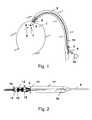
- FIG. 1schematically a rotor blood pump, which is inserted by means of a hollow catheter in the left ventricle of a heart
- Fig. 2in a more detailed account the pump
- Fig. 3schematically an embodiment of a rotor with a hub
- Fig. 4an embodiment of a rotor with a hubless airfoil
- Fig. 5the structure of a rotor with a hub and reinforcing struts for the airfoil body
- Fig. 1schematically a rotor blood pump, which is inserted by means of a hollow catheter in the left ventricle of a heart
- Fig. 2in a more detailed account the pump
- Fig. 3schematically an embodiment of a rotor with a hub
- Fig. 4an embodiment of a rotor with a hubless airfoil
- Fig. 5the structure of a rotor with a hub and reinforcing struts for the airfoil body
- Fig. 6a configuration of struts for a rotor, wherein the struts protrude perpendicularly from the longitudinal axis of the rotor
- Fig. 7a configuration with struts which are inclined with respect to the axis of rotation of the rotor
- Fig. 8a cross section through a rotor with a massive hub
- Fig. 9a cross section through a rotor with a hollow hub
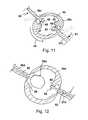
- Fig. 10a cross section through a rotor with a hollow hub and two blades, which are suspended in recesses of the hub
- Fig. 11a rotor in cross section with a hollow hub and stop bodies
- Fig. 12a rotor in cross-section with a hollow hub and in this projecting struts of two blades with corresponding stop configurations
- Fig. 13in cross-section a rotor with two blades and struts embedded therein
- Fig. 14in the partial cross-section a rotor with two blades, are integrated into the struts within cavities
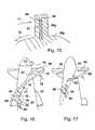
- Fig. 15in cross-section a rotor with an airfoil and a strut integrated therein in a cavity which is longer than the strut
- Fig. 16a three-dimensional external view of a rotor with blades and tensile elements for supporting the blades
- Fig. 17a rotor with a plurality of blades and various, these supporting tension elements.
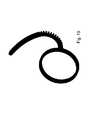
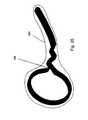
- Fig. 18 to 20an embodiment of a reinforcing strut in different states, wherein the strut has on the flow suction side recesses for better compressibility, wherein the recesses are largely closed in the operating state and form a stop together with the embedded base material
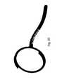
- Fig. 21 to 23an embodiment of a reinforcing strut in different states, wherein the strut is optimized in terms of uniform stress distributions in the material
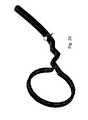
- FIGS. 24 to 26an embodiment of a reinforcing strut in different states, wherein the strut and a flexible tension member are integrally formed.
- Fig. 1schematically shows the left ventricle 1 a heart chamber 1 and a blood vessel 2 opening into this, in which by means of a lock 3, a hollow catheter 4 is inserted.
- the pump 5has at its distal end to a suction cage 8, in, as by the Arrows 6, 7 indicated, blood is sucked. This is squeezed out through outflow openings 9 inside the blood vessel 2 behind the heart valve.
- the pump 5has a rotor with conveying elements, which can be driven in rotation about its longitudinal axis by means of a flexible shaft 11, which runs through the hollow catheter 4 and is connected to a drive motor 10 outside the patient's body.
- the typical speed of the rotoris in operation at a few thousand to about 50 000 U / min.
- a pump housing 12Within a pump housing 12, the rotor 13 is rotatably supported by means of a rotor shaft 14 at the proximal end 15, ie the end closer to the lock 3, as well as at the distal end 16. Beyond the storage at the distal end 16 or between the distal end and the rotor 13 itself suction openings are provided for the blood, for example in the form of a suction cage, ie an opening of the housing 12th
- the rotor 13itself is made in one piece, with a hub and two integrally connected helical blades.
- an outflow hose 17sets, which is positioned at the transition between the blood vessel 2 and the ventricle 1 with proper positioning of the pump within the heart valve, so that the outflow openings 18 are within the blood vessel 2.
- an additional spacer memberwhich is bent at the free end, for example, spirally shaped to prevent the abutment of the pump to body tissue and also the insertion of the pump by a To facilitate blood vessel.
- the elementis intended to prevent the pump from getting caught on vessel walls or the inner walls of a ventricle.
- Fig. 3shows a rotor 13a with two helical blades 19, 20, which consist of plastic, with the hub 21 are integrally formed and can, for example, support struts in their interior.
- the airfoil body of the airfoils 19, 20may be made of, for example, polyurethane in solid form or of a foam, and the struts may be integrated into the body. The production can take place in that the struts are encapsulated with a corresponding plastic.
- Fig. 4shows schematically in three-dimensional view a rotor without a hub with a single airfoil 22. Also in this corresponding struts can be embedded.
- the blade 22is frontally driven by a shaft piece 23.
- Fig. 5shows a rotor 13b with a hub 24 and two rows of struts 25, 26, 27, which are distributed in the form of a helix circumferentially on the hub 24 and project radially from this.
- the struts 25, 26, 27may, for example, each consist of a pair of two individual struts, which are interconnected at their end remote from the axis of rotation.
- the axis of rotationis in the Fig. 5 denoted by 29.
- the strutscan for example be fastened together on one bar per blade, wherein the strip is flexible and can be in a recess 28, which rotates on the hub 24, let move.
- directly adjacent strutsare connected in pairs, and the pairs are connected to each other in their region close to the axis of rotation.
- Fig. 7shows struts 30, 31, 32, 33 which are connected in pairs in each case in their region remote from the axis of rotation 29 and connected by means of a continuous strip 34 in the region close to the axis of rotation.
- the individual struts 30, 31, 32, 33are inclined relative to the axis of rotation 29, for example at an angle of approximately 30 ° or 60 °.
- Fig. 8shows a cross section of a rotor with a solid hub 35, on whose shell-side surface two blades 36, 37 in the second state, ie in slightly pre-curved shape, are located befindlich. During operation, ie upon rotation of the rotor in the direction of the arrow 38, the blades 36, 37 continue to almost to the extension.
- the rotorcan also be opposite the in Fig. 8 illustrated configuration are further compressed by the blades are pressed closer to the hub 35.
- Fig. 9shows two blades 36a, 37a, which protrude into a cavity 39 of a hub 35a.
- the blades 36a, 37aform two-armed levers, each mounted in the wall of the hollow hub 35a.
- Fig. 10shows a further development of the embodiment Fig. 9 in that at the hub 35b, the wall thickness in the region 40, 41, where the blades 36b, 37b penetrate the wall of the hub 35b, is weakened in each case by thinning. As a result, the blades are pivotally mounted in a kind of film joints in corresponding areas of the hub.
- Fig. 11shows a corresponding constellation, in which two blades 36c, 37c each protrude with their inner ends and attached stopper members 42, 43 in the cavity 44 of a hub 35c.
- the stopper members 42, 43cooperate in the direction of the arrows 45, 46 during operation of the rotor with corresponding stops 47, 48, so that the blades 36c, 37c are supported in the third state and thus assume the desired operating state.
- the stopper body 42, 43 of the stops 47, 48, and the blades 36 c, 37 ccan solve in the in the Fig. 11 dashed line positions are brought.
- the bladesare pivoted within the corresponding weakened areas of the hub body 35c.
- Fig. 12shows a further embodiment of a rotor with a hub body 35d and two blades 36d, 37d, each having the struts 52, 53.
- the bladesend on the outer surface of the hub 35d, and only the struts 52, 53 protrude into the interior of the hub.
- the strut 52 of the airfoil 36druns in the interior of the hub 35d in a circular disk-shaped stopper body 52a, which can be made in one piece with the strut 52, for example punched out of a metal sheet.
- the stopper body 52ais shaped such that it strikes against a stop 56, which does not require any special design in this case, for limiting the movement of the blade 36d when subjected to a corresponding load in the third state.
- a plurality of the stopper bodies 52amay also be connected to each other to form a framework for the struts 52 and to hold them while, for example, being overmoulded with the material of the airfoil body.
- Fig. 13shows a rotor with a hub 35e in a solid construction, with two blades 36e, 37e, in which struts 57, 58 are integrated.
- the strut 57extends from a first center distance, represented by the dashed line 59, to a second center distance, represented by the line 60.
- the strut 57is therefore not sufficient to the hub 35e.
- the strut 58extends into the hub 35e and ends at the center distance 61, d. h., It is radially shorter with respect to the rotor axis than the airfoil 37e.
- the differences of the struts 57, 58are shown by way of example only on a single rotor.
- the strutsare each encapsulated with the material of the airfoil body and adhere partially or on all sides to the material.
- a hub 35fis illustrated with two exemplary airfoils 36f, 37f, each receiving a strut 62, 63.
- the strut 62is smaller in length and width than the cavity 64 in which it is within the airfoil 36f.
- the strut 63is firmly enclosed at its radially outer end 65 of the material of the airfoil 37 f and can move in the rotation axis close region 66 within the cavity of the airfoil 37 f and there occupy different positions depending on the compression or expansion state, that is, to different walls of the Create a cavity.
- This cavitycan be designed asymmetrically.
- the corresponding strut 63can support the blade 37f, while the rotor can be strongly compressed without a supporting effect of the strut by the strut can dodge within the airfoil. Accordingly, it can also be provided that the strut is firmly enclosed and fixed in the airfoil only at its near-axis end and has freedom of movement in the region away from the axis.
- the strut 67is designed to be shorter in the radial direction than the cavity 68 within the airfoil 36g, so that in operation, for example by centrifugal forces, the strut 37 can slide radially outward and support the airfoil there. It can then be moved radially inward during a compression movement, for example by corresponding bevels on the radially outer end of the strut, so that it impedes a compression less than in the radially outer region.
- the bevelsare shown at the radially outer end of the strut 67 and designated 69.
- the rotational movement of the rotoris symbolized by the arrow 70 and the fluid counterpressure against the blade 36g by the arrow 71.
- the Fig. 16shows in three-dimensional view a rotor 72 which rotates in operation in the direction of arrow 73. Accordingly, forces on the blade blades 74 result as a result of the fluid counterpressure, which are represented by the arrows 75, 76.
- tension members 77, 78, 79, 80are illustrated, which represent different examples of their orientation and attachment.
- the tension members 77, 78extend from a radially outer point on the airfoil 74 to a radially inner point near the hub 81.
- the tension member 79is fixed on the one hand at a point 82 on the blade 74, on the other hand at the point 83 on the surface of the hub 81 at a distance from the foot of the airfoil.
- the tension member 80is sheet-shaped as a thin film and secured at a point 84 on the airfoil, while the base 85 is mounted on the surface of the hub 81 at a distance from the foot of the airfoil 74.
- the foil 80may be oriented such that it does not obstruct the fluid flow.
- the corresponding tension elementsare limp and do not hinder movement of the blades 74.
- the tension memberslimit further overstretching and thus stabilize the airfoils.
- the tension elementscan for example consist of a band with glass fiber reinforcement or essentially only of glass fibers or of polycarbonate fibers, for example of Kevlar, in order to achieve the smallest possible thickness with correspondingly high tensile strength and strength.
- the tension elementscan also consist of a polymer film, for example of PEEK, but also of a metal foil, for example of nitinol or titanium, in order to achieve the desired effect.
- such materials or material combinationsare particularly suitable for these flexible tension elements, which are also used for so-called non-compliant balloon catheters, since these usually combine the mechanical properties desired here with the likewise required biocompatible and blood-compatible properties.
- tension elements 86, 87are shown on the airfoil 74, wherein the tension element 86 is glued, printed or otherwise secured to the surface of the airfoil 74 and has a tortuous shape, which only in the first or second state of the airfoil in this form is present.
- this tension memberassumes the stretched shape indicated at 87 to then be taut and prevent further movement of the airfoil beyond the extended condition.
- a rotoris shown with a plurality of blades 88, 89, 90, which respectively revolve only partially around the hub 91 and can be supported individually by means of tension members 92, 93, 94.
- the tension members 92may be formed as films and continue the contour of the corresponding blades 88 hydrodynamically favorable. They are positioned and taut to support the blades in the stretched condition.
- the airfoils 88, 89, 90may have integrated struts 95 therein.
- the respective rotorscan each be arranged in a compressible and expandable housing which is expandable, for example, by means of the erecting airfoils.
- FIGS. 18 to 20show a further embodiment of a stiffening strut.
- Fig. 18the first state shown, so the power-free state.
- Fig. 19is the second state, ie the state in which the stiffening strut / the blade / the rotor is radially compressed. This is done primarily by tilting the stiffening strut in Fig. 19 to the left, ie counterclockwise.
- Fig. 20is the third state, that is, the operating state of the rotor / the airfoil / the stiffening strut shown, in which actually fluid is conveyed.
- the fluid counterpressureacts clockwise, ie, the direction of rotation of the rotor is counterclockwise. This is a weakening on the Strömungssaugseite (in Fig. 20 on the radial arm of the stiffening brace below). The flow pressure side is unattenuated in this case.
- stiffening strutis shown without additional material in which the stiffening strut is embedded.
- this stiffening strutis attached to the axial flow leading edge of the rotor, and the in Fig. 18 to the right projecting radial arm of the stiffening strut is completely surrounded by the embedding material, in this case plastic.
- Thisis also the case between the weakening slots.
- the blade surfaceis in this case created so that no weaknesses are visible from the outside.
- compressingsee Fig. 19
- a "mechanical stop"is given. In this case, the inner walls of the slots do not have to strike against each other, since the embedding mass / embedding material / plastic located in this intermediate area is compressed and thus guarantees a deformation limitation.
- Fig. 21again shows the first state in which the deformation strut / the rotor protrudes force-free. All features are as in the aforementioned embodiment after FIGS. 18-20 unless otherwise stated below.
- Fig. 22shows the second state
- Fig. 23again, the third state
- no weakening in the form of slitsis shown, but instead, near the circular hub region, a kink is shown representing a "reinforcement curve". This is designed so that on the one hand during elastic deformation in the in Fig. 22 shown state a slight bending is possible and on the other hand in the state after Fig. 23 a mechanical stop is given without the material ever entering the plastic area where irreversible deformation would occur.
- FIGS. 24 to 26show a further embodiment, which the embodiment according to FIGS. 21-23 is similar, although in the transition region from the annular hub region to the radial boom toward a radially inwardly located in the hub ring weakening is shown which the elasticity of the boom, especially when moving from in Fig. 24 shown first state in the in Fig. 25 shown second state facilitates.
- the guarantee of the mechanical stop in the in Fig. 26 shown third statewhich can be done for example by the design of the tapered portion (100) as a tension strut.
- the tapered region (100)is thereby good at taking the First State bendable, but takes in the third state, an approximately elongated shape, which opposes further avoidance against the flow pressure increased resistance. It should be mentioned again that in the Figures 20 . 23 and 26 It is assumed, in each case, that the direction of rotation of the rotor is counterclockwise, thereby resulting in an expansion of the radial arm in the clockwise direction. In Fig. 26 the outline of an airfoil 101 is further schematically shown, which in the illustrated embodiment, the strut completely encloses so that the fluid comes into contact with a uniform as homogeneous surface. This ensures that the fluid undergoes uniform as possible acceleration with low shear stress peaks in the operating state.
Landscapes
- Health & Medical Sciences (AREA)
- Engineering & Computer Science (AREA)
- Heart & Thoracic Surgery (AREA)
- Mechanical Engineering (AREA)
- Cardiology (AREA)
- Biomedical Technology (AREA)
- Anesthesiology (AREA)
- Hematology (AREA)
- Life Sciences & Earth Sciences (AREA)
- Animal Behavior & Ethology (AREA)
- General Health & Medical Sciences (AREA)
- Public Health (AREA)
- Veterinary Medicine (AREA)
- Vascular Medicine (AREA)
- General Engineering & Computer Science (AREA)
- Architecture (AREA)
- Structures Of Non-Positive Displacement Pumps (AREA)
- Transplantation (AREA)
Abstract
Description
Translated fromGermanDie Erfindung liegt auf dem Gebiet des Maschinenbaus und der Mechanik und befasst sich mit Rotoren für Pumpen.The invention is in the field of mechanical engineering and mechanics and deals with rotors for pumps.
Rotorpumpen sind vielseitig einsetzbar und bei entsprechender Ausgestaltung und Drehzahl des Rotors sehr leistungsfähig. Grundsätzlich können die Rotoren als axial fördernde oder zentrifugal fördernde Rotoren ausgebildet sein und weisen entsprechende Schaufelblätter auf.Rotor pumps are versatile and very powerful with appropriate design and speed of the rotor. In principle, the rotors can be designed as axially conveying or centrifugally conveying rotors and have corresponding blades.
Von besonderem Interesse sind derartige Pumpen dann, wenn sie im Verhältnis zu ihrer Förderleistung dadurch sehr klein ausgebildet werden können, dass sie zum Transport komprimiert und für den Betrieb expandiert werden können. Eine spezielle Anwendung derartiger Pumpen im medizinischen Bereich betrifft die invasiven Pumpen, die in radial komprimiertem Zustand in den Körper eines Patienten hinein befördert und dort expandiert werden können, um die gewünschte Förderleistung zu erzielen.Of particular interest are such pumps when they can be made very small in relation to their capacity, that they can be compressed for transport and expanded for operation. A special application of such pumps in the medical field relates to invasive pumps, which can be transported in a radially compressed state into the body of a patient into and expanded there to achieve the desired flow rate.
Solche Pumpen können beispielsweise als herzunterstützende Blutförderpumpen eingesetzt werden und durch ein Blutgefäß in einen Körperhohlraum befördert werden, um dort radial expandiert zu werden. Dazu ist typischerweise sowohl der Rotor als auch, soweit vorhanden, ein entsprechendes Pumpengehäuse radial komprimierbar und expandierbar.Such pumps may be used, for example, as cardiac assistive blood delivery pumps and conveyed through a blood vessel into a body cavity to be radially expanded there. For this purpose, typically both the rotor and, if present, a corresponding pump housing are radially compressible and expandable.
Eine solche Pumpe ist beispielsweise aus dem
Eine sehr ähnliche Pumpe ist aus der US-Patentanmeldung
Vor dem Hintergrund des Standes der Technik liegt der vorliegenden Erfindung die Aufgabe zugrunde, einen Rotor für eine Pumpe zu schaffen, der mit möglichst geringem Kraftaufwand radial komprimierbar ist, der andererseits im Betrieb ebenso leicht expandierbar ist und im expandierten Zustand die für die Schubwirkung erforderliche Stabilität aufweist.Against the background of the prior art, the present invention has the object to provide a rotor for a pump which is radially compressible with the least possible force, on the other hand in the operation is just as easy to expand and in the expanded state required for the thrust stability having.
Die Aufgabe wird gemäß der Erfindung mit den Merkmalen des Patentanspruchs 1 gelöst.The object is achieved according to the invention with the features of
Es ist dazu gemäß der Erfindung ein radial komprimierbarer und expandierbarer Rotor für eine Pumpe mit wenigstens einem Schaufelblatt vorgesehen, wobei das Schaufelblatt einen Schaufelblattkörper aufweist, dessen Material elastisch verformbar ist, sowie wenigstens eine Versteifungsstrebe, die in das Material des Schaufelblattkörpers wenigstens teilweise eingebettet ist.It is according to the invention, a radially compressible and expandable rotor for a pump with at least one airfoil provided, wherein the airfoil has an airfoil body whose material is elastically deformable, and at least one stiffening strut, which is at least partially embedded in the material of the airfoil body.
Der erfindungsgemäße Rotor zeigt vorzugsweise eine Stützstruktur (= Streben), die keine geschlossene Randstruktur bzw. Randkurve aufweist. Das heißt, dass in der vorliegenden Erfindung vorzugsweise einzelne Streben bzw. Lamellen vorgesehen sind, die weitgehend unabhängig voneinander verformbar sind und dadurch einerseits eine gute Komprimierung des Rotors ermöglichen, andererseits aber auch eine ausreichende Stabilisierung/Steifigkeit im Pumpbetrieb ermöglichen. Der Schaufelblattkörper hat geometrieerhaltende Eigenschaften gegenüber Verformungen im Pumpbetrieb, die lokal durch Versteifungsstreben versteift werden.The rotor according to the invention preferably has a support structure (= struts) which has no closed edge structure or edge curve. That is, in the present invention, preferably single struts or fins are provided which are largely deformable independently of each other and thereby on the one hand enable a good compression of the rotor, but on the other hand also allow sufficient stabilization / rigidity in pumping operation. The airfoil body has geometry-preserving pumping deformation properties that are locally stiffened by stiffening struts.
Dabei wird die Oberfläche des Schaufelblattkörpers von den Streben nicht durchbrochen, so dass keine Störung des Fluidstroms hervorgerufen wird. Vorzugsweise ist die Schaufelblattstärke (d. h. die Gesamt dicke des Schaufelblattes einschließlich eventueller Hohlräume) mindestens so dick/groß wie die größte Dicke der hierzu benachbarten bzw. hiermit verbundenen Streben. Dadurch ist die jeweilige Strebe allseits vom Kunststoffmaterial des Schaufelblatts bedeckt, und es ergibt sich (anders als beispielsweise bei folienbespannten Metallgerüsten) eine homogene, strömungsgünstige Schaufeloberfläche.The surface of the blade body is not broken by the struts, so that no Disturbance of the fluid flow is caused. Preferably, the blade thickness (ie, the total thickness of the airfoil including any voids) is at least as thick / large as the largest thickness of the adjacent thereto or hereby connected struts. As a result, the respective strut is covered on all sides by the plastic material of the airfoil, and it results (unlike, for example, in foil-covered metal frameworks) a homogeneous, flow-favorable blade surface.
Durch diese Konstruktion können die verschiedenen mechanischen Anforderungen an den Rotor bzw. das Schaufelblatt auf verschiedene Materialien bzw. konstruktive Elemente verteilt werden. Die Streben können derart gebaut und positioniert sein, dass sie die Komprimierung des Schaufelblattes vom ersten in den zweiten Zustand nicht behindern, dass sie jedoch andererseits den Rotor im dritten, expandierten Zustand hinreichend stabilisieren. Die Streben übernehmen damit die Spannungen, während das Material des Schaufelblattkörpers die erforderliche Dehnbarkeit aufweist. Insoweit kann durch die Verwendung eines Kompositwerkstoffs auch die Gesamtmasse und das Gesamtvolumen des Rotors bzw. des Schaufelblattes minimiert werden. Dies führt zu einem geringen Durchmesser im zweiten, komprimierten Zustand.By this construction, the different mechanical requirements of the rotor or the blade can be distributed to different materials or structural elements. The struts may be constructed and positioned such that they do not hinder the compression of the airfoil from the first to the second state, but on the other hand, they sufficiently stabilize the rotor in the third, expanded state. The struts thus take over the stresses, while the material of the airfoil body has the required extensibility. In that regard, the use of a composite material and the total mass and the total volume of the rotor or the airfoil can be minimized. This leads to a small diameter in the second, compressed state.
Typischerweise bestehen die Streben aus einem steiferen Material als der Schaufelblattkörper, beispielsweise einem steifen Kunststoff oder einer Metalllegierung bzw. einem Metall.Typically, the struts are made of a stiffer material than the airfoil body, such as a rigid plastic or metal alloy or metal.
Die Konstruktion ist derart gestaltet, dass der Rotor ohne äußere Krafteinwirkung einen ersten Zustand einnimmt, von dem er einerseits durch eine radiale Kompression in einen zweiten, komprimierbaren Zustand zu Zwecken des Transportes überführbar ist, während er von dem ersten Zustand ebenso im Betrieb durch Aufrichten des Schaufelblattes / der Schaufelblätter in einen dritten, expandierten Zustand überführbar ist.The design is designed such that the rotor assumes a first state without external force, of which he on the one hand by a radial compression in a second, compressible state for transport purposes is convertible, while it can be converted from the first state also in operation by raising the airfoil / the blades in a third, expanded state.
Dadurch, dass der erste Zustand des Rotors gegenüber dem Betriebszustand schon teilweise komprimiert ist, sollen die zur endgültigen Kompression notwendigen Radialkräfte möglichst minimiert werden. Zudem nimmt das Schaufelblatt bzw. nehmen die Schaufelblätter im ersten Zustand eine Vorzugsposition ein, die unter der Wirkung des Fluidgegendrucks für ein Aufrichten der Schaufelblätter sowie dafür sorgt, dass im zweiten, komprimierten Zustand ihre Position optimiert ist.Because the first state of the rotor is already partially compressed relative to the operating state, the radial forces required for the final compression should be minimized as far as possible. In addition, the airfoil takes or take the blades in the first state a preferred position, which ensures under the effect of fluid back pressure for erecting the blades and that in the second compressed state, their position is optimized.
Der Rotor kann vorteilhaft nabenlos ausgestaltet sein, und die Streben können sich bezüglich der Rotationsachse in Radialrichtung von einem ersten Achsabstand bis zu einem zweiten Achsabstand erstrecken. Dies bedeutet, dass die Streben sich radial nach innen nicht bis zur Rotationsachse erstrecken müssen, sondern in einem endlichen Abstand von dieser beginnend sich im Schaufelblatt radial nach außen erstrecken. Sie können radial außen bis zum Ende des Schaufelblattes verlaufen oder in einem zweiten Achsabstand vor dem Ende des Schaufelblattes enden. Das Schaufelblatt selbst kann geteilt sein und den rotationsachsnahen Bereich frei lassen, oder es kann sich als eine einzige durchgehende Schaufel über den zentralen Bereich hinaus, beispielsweise als ein einzelnes spiralförmiges Blatt, erstrecken.The rotor can advantageously be designed without hubs, and the struts can extend with respect to the axis of rotation in the radial direction from a first axial spacing to a second axial spacing. This means that the struts do not have to extend radially inward to the axis of rotation, but at a finite distance from this beginning radially extending in the blade to the outside. You can run radially outward to the end of the airfoil or end in a second center distance before the end of the airfoil. The airfoil itself may be split and free of the region near the axis of rotation, or it may extend beyond the central region as a single continuous blade, for example as a single spiral blade.
Andererseits kann eine Nabe vorgesehen sein, mit der das Schaufelblatt verbunden und gegenüber der das Schaufelblatt schwenkbar ist. In diesem Fall ist das Einleiten der Antriebskräfte in das Schaufelblatt durch die Nabe vereinfacht möglich, während bei einem nabenlosen Rotor die Antriebskraft stirnseitig in die Schaufelblätter eingeleitet werden muss.On the other hand, a hub may be provided, with which the blade is connected and opposite to the Airfoil is pivotable. In this case, the introduction of the driving forces into the blade through the hub is made possible in a simplified manner, while in the case of a hubs-less rotor the driving force has to be introduced into the blade blades at the end.
Vorteilhaft kann wenigstens eine Strebe, insbesondere auch mehrere oder alle Streben, sich bis radial in die Nabe hinein erstrecken. Die Streben können beispielsweise als einzelne Körper oder als ein verbundenes Gerüst in den Nabenkörper eingesteckt oder in eine Nut des Nabenkörpers eingezogen werden, um das Stützgerüst des Schaufelblattes zu bilden. Eine derartige nutenförmige Ausnehmung des Nabenkörpers verläuft typischerweise helixartig an seiner Mantelfläche entlang. Im Querschnitt kann die Nut beispielsweise schwalbenschwanzförmig ausgebildet sein, um die Streben zuverlässig zu halten.Advantageously, at least one strut, in particular also several or all struts, extend radially into the hub. For example, the struts may be plugged into the hub body as a single body or as a connected stand, or retracted into a groove of the hub body to form the support framework of the airfoil. Such a groove-shaped recess of the hub body typically runs helically along its lateral surface. In cross-section, the groove may be formed, for example, dovetailed to reliably hold the struts.
Es kann vorteilhaft allerdings auch vorgesehen sein, dass wenigstens eine Strebe, insbesondere mehrere Streben oder alle Streben, sich radial von einem ersten Achsabstand außerhalb der Nabe bis zu einem zweiten Achsabstand erstrecken. In diesem Fall kann beispielsweise das Anklappen des Schaufelblattes an die Nabe erleichtert sein. Jedoch ist auch bei Streben, die sich in den Nabenkörper hinein erstrecken oder einstückig durch die Nabe hindurch verlaufen, ein Anklappen durch entsprechend optimierte Gestaltung gut möglich.However, it can also be advantageously provided that at least one strut, in particular a plurality of struts or all struts, extend radially from a first center distance outside the hub to a second center distance. In this case, for example, the folding of the airfoil to the hub can be facilitated. However, even with struts which extend into the hub body or extend integrally through the hub, folding through well-optimized design is possible.
Die Streben können untereinander alle oder in Gruppen miteinander verbunden sein, wobei sie vorteilhaft innerhalb der rotationsachsnahen Hälfte ihrer radialen Ausdehnung, im expandierten Zustand des Rotors betrachtet, miteinander verbunden sein können. Insbesondere können sie auch an ihren rotationsachsnahen Enden miteinander verbunden sein, vorteilhaft auch ausschließlich dort. Es kann auch vorgesehen sein, dass die Streben jeweils paarweise an ihren rotationsachsfernen Enden miteinander verbunden sind und somit Schlaufen bilden, wobei die Schlaufen jeweils untereinander im achsnahen Bereich verbunden sind. Hierdurch ergibt sich eine gute Versteifung des Schaufelblattes in Richtung senkrecht zur Schubbelastung und eine gute Verformbarkeit innerhalb der Ebene des Schaufelblattes, so dass im Betrieb eine gute Stabilisierung durch die Streben ermöglicht wird, jedoch zur Kompression die Streben eine entsprechende Beweglichkeit im achsfernen Bereich des Schaufelblattes untereinander aufweisen können. Die Streben können als strangförmige Körper, beispielsweise in Form eines Drahtes, ausgebildet sein, jedoch auch als flache Teile eines blechartigen Körpers. In einer vorteilhaften Ausprägung können sie beispielsweise aus einem vollen Blech ausgestanzt oder durch entsprechende Schneidetechniken, beispielsweise Laserschneiden, Ätzen oder Erodieren, ausgeschnitten sein.The struts may be connected to each other all or in groups with each other, and they may be advantageous within the rotationsachsnahen half their radial extent, viewed in the expanded state of the rotor, connected to each other. Especially they can also be connected to each other at their ends close to the rotation axis, advantageously also exclusively there. It can also be provided that the struts are connected in pairs at their ends remote from the axis of rotation and thus form loops, wherein the loops are each connected to one another in the region close to the axis. This results in a good stiffening of the blade in the direction perpendicular to the thrust load and a good deformability within the plane of the airfoil, so that a good stabilization is made possible by the struts, but for compression struts a corresponding mobility in the off-axis region of the airfoil with each other can have. The struts may be formed as a strand-shaped body, for example in the form of a wire, but also as flat parts of a sheet-like body. In an advantageous embodiment, for example, they can be punched out of a solid sheet or cut out by appropriate cutting techniques, for example laser cutting, etching or eroding.
Vorteilhaft sind die Streben mit dem Material des Schaufelblattkörpers umspritzt, umgossen oder in flüssigem Zustand benetzt, wobei entsprechend eine nachfolgende Härtung vorgesehen sein kann.Advantageously, the struts are encapsulated with the material of the airfoil body, cast around or wetted in the liquid state, wherein a corresponding subsequent curing can be provided accordingly.
Weiterhin kann vorteilhaft vorgesehen sein, dass die Streben in Ausnehmungen des Schaufelblattkörpers angeordnet sind, welche in Längs- und/oder in Querrichtung der jeweiligen Strebe größer sind als die Außenmaße der Strebe(n).Furthermore, it can be advantageously provided that the struts are arranged in recesses of the airfoil body, which are greater in the longitudinal and / or in the transverse direction of the respective strut than the outer dimensions of the strut (s).
Dadurch, dass die Ausnehmungen im Schaufelblattkörper in wenigstens einer Ausdehnungsrichtung größer sind als die Maße der jeweiligen Strebe, kann die Strebe in den verschiedenen Zuständen des Rotors in unterschiedlichen Positionen in der jeweiligen Ausnehmung liegen. Damit lassen sich unterschiedliche Versteifungsgrade des Schaufelblattes in den verschiedenen Zuständen realisieren, so dass einerseits das Schaufelblatt in einer ersten Position im gestreckten Zustand des Schaufelblattes eine starke Versteifungswirkung ausüben kann, andererseits dieselbe Strebe sich beim Komprimieren des Rotors innerhalb ihrer Ausnehmung derart umlagern kann, dass sie die Kompression nur unwesentlich behindert.Characterized in that the recesses in the airfoil body in at least one direction of expansion are greater than the dimensions of the respective strut, the strut may be in different states of the rotor in different positions in the respective recess. This allows different degrees of reinforcement of the airfoil realized in the various states, so that on the one hand the blade can exert a strong stiffening effect in a first position in the extended state of the airfoil, on the other hand, the same strut can be rearranged during compression of the rotor within its recess such that they the compression is only marginally impeded.
Es kann vorteilhaft auch vorgesehen sein, dass wenigstens eine Strebe auf ihrer der Druckseite des Schaufelblattes zugewandten Fläche und/oder auf ihrer der Saugseite zugewandten Fläche an dem Material des Schaufelblattkörpers haftet. Beispielsweise kann, wenn die Strebe nur auf der der Saugseite zugewandten Fläche mit dem Material des Schaufelblattkörpers haftend verbunden ist und das Material des Schaufelblattkörpers inkompressibel ist, eine hohe Steifigkeit im gestreckten Zustand erreicht werden. Es kann je nach den Erfordernissen der Konstruktion die jeweilige Strebe nur auf der der Saugseite oder der Druckseite zugewandten Fläche haftend mit dem Schaufelblattkörper verbunden sein, oder die Strebe kann rundum an allen ihren Flächen am Schaufelblattkörper haften.It may also be advantageously provided that at least one strut adheres to the material of the airfoil body on its surface facing the pressure side of the airfoil and / or on its surface facing the suction side. For example, if the strut is adhesively bonded to the material of the airfoil body only on the suction-side facing surface and the material of the airfoil body is incompressible, high rigidity in the stretched state can be achieved. Depending on the requirements of the construction, the respective strut may be adhesively bonded to the airfoil body only on the surface facing the suction side or the pressure side, or the strut may adhere all around to the airfoil body.
In einer weiteren Ausführungsform kann die Haftung zwischen Schaufelblattkörper und Strebe(n) unterschiedlich ausgebildet sein. Beispielweise kann der Rotor so gestaltet werden, dass der Schaufelblattkörper im Bereich der Nabe fest mit den Streben verbunden ist, wogegen er im Bereich der Streben fern der Nabe nicht haftet und somit beim Komprimieren gegenüber den Streben gleiten kann. Dies kann z. B. durch den lokalen Einsatz von Haft- bzw. Trennmitteln bzw. unterschiedliche Oberflächengestaltung (d. h. Rauigkeit, Formschluss) geschehen. Hier sind beliebige Ausgestaltungen möglich; so kann z. B. auch der Rotor so gestaltet werden, dass der Schaufelblattkörper im Bereich der Nabe gegenüber den Streben gleitet und im nabenfernen Bereich fest mit den Streben verbunden ist. Dies kann auch über die Länge des Rotors variieren.In a further embodiment, the adhesion between the blade body and strut (s) may be formed differently. For example, the rotor may be configured so that the airfoil body in the region of the hub is firmly connected to the struts, whereas he in the area of the struts far from the hub is not liable and thus can slide when compressing against the struts. This can be z. B. by the local use of adhesive or release agents or different surface design (ie roughness, positive locking) happen. Any configurations are possible here; so z. B. also the rotor are designed so that the blade body slides in the region of the hub opposite the struts and is firmly connected to the struts in the area remote from the hub. This can also vary over the length of the rotor.
Die Strebe(n) können wenigstens teilweise aus einem superelastischen Material, insbesondere einem superelastischen Polymer, oder einer Gedächtnislegierung, insbesondere Nitinol, bestehen. Dabei wird unter einem superelastischen Material ein solches verstanden, das wenigstens eine elastisch Dehnung um 2 % übersteht und danach kraftfrei im Wesentlichen in seine Ausgangsposition zurückkehrt.The strut (s) may at least partially consist of a superelastic material, in particular a superelastic polymer, or a memory alloy, in particular nitinol. In this case, a super-elastic material is understood to mean one that withstands at least one elastic elongation by 2% and then returns substantially without force substantially to its starting position.
Auch das Material des Schaufelblattkörpers kann aus einem superelastischen Werkstoff bestehen, beispielsweise um Rissbildung, besonders an den radial äußeren Spitzen des Schaufelblattes und im Bereich der Schaufelblattwurzel an der Nabe zu minimieren bzw. zu verhindern.Also, the material of the airfoil body may consist of a superelastic material, for example, to minimize or prevent cracking, especially at the radially outer tips of the airfoil and in the region of the airfoil root at the hub.
Die Strebe bzw. Streben können wenigstens teilweise schräg gegenüber der Axialrichtung der Rotationsachse angeordnet sein, so dass sie zur Axialrichtung einen Winkel von weniger als 90° einnehmen. In diesem Fall kann bei der Kompression in den zweiten Zustand das jeweilige Schaufelblatt nicht nur in Umfangsrichtung an die Nabe angelegt werden, sondern auch teilweise in Richtung der Rotationsachse angeklappt werden. Dies hat den Vorteil, dass eine Kompressionsbewegung teilweise in der Ebene des Schaufelblattes stattfindet, da in dieser Richtung üblicherweise keine Versteifung des Schaufelblattes durch die Streben notwendig ist. Trotz guter Versteifungseigenschaften senkrecht zur Schaufelblattebene können die Streben daher eine begrenzte Bewegung in der Schaufelblattebene zulassen.The strut or struts may be arranged at least partially obliquely with respect to the axial direction of the axis of rotation, so that they occupy an angle of less than 90 ° to the axial direction. In this case, in the compression in the second state, the respective airfoil not only in the circumferential direction be applied to the hub, but also partially folded in the direction of the axis of rotation. This has the advantage that a compression movement takes place partly in the plane of the airfoil, since in this direction usually no stiffening of the airfoil by the struts is necessary. Therefore, despite good stiffening properties perpendicular to the blade plane, the struts can allow limited movement in the blade plane.
Eine weitere vorteilhafte Ausgestaltung der Erfindung sieht vor, dass das Schaufelblatt auf seiner Druckseite wenigstens ein zugfestes Element in Form eines Bandes oder einer Folie aufweist, das an wenigstens einem radial äußeren Befestigungspunkt und wenigstens einem radial inneren Befestigungspunkt mit einer Strebe und/oder dem Schaufelblattkörper verbunden ist. Ein solches zugfestes Element stabilisiert das Schaufelblatt im dritten, gestreckten Zustand, ohne die Kompression in den ersten Zustand merklich zu behindern oder zu erschweren. Das entsprechende zugfeste Element kann entweder direkt in radialer Richtung oder auch schräg zur Rotationsachse, insbesondere parallel oder im Wesentlichen parallel zu den Streben verlaufen.A further advantageous embodiment of the invention provides that the airfoil has on its pressure side at least one tensile element in the form of a band or a foil which is connected to a strut and / or the airfoil body at at least one radially outer attachment point and at least one radially inner attachment point is. Such a tensile element stabilizes the airfoil in the third, extended state, without significantly hindering or complicating the compression in the first state. The corresponding tensile element can either extend directly in the radial direction or obliquely to the axis of rotation, in particular parallel or substantially parallel to the struts.
Es kann zudem vorteilhaft vorgesehen sein, dass der Rotor wenigstens auf der Druckseite des Schaufelblattes wenigstens ein zugfestes Element in Form eines Bandes oder einer Folie aufweist, das einerseits an einer Strebe und/oder dem Schaufelblattkörper in radialem Abstand von der Rotationsachse sowie andererseits an einer Nabe befestigt ist. Das zugfeste Element kann somit am Fuße des jeweiligen Schaufelblattes auch von dessen Wurzel beabstandet an der Nabe befestigt sein. Das zugfeste Element kann auch als Folie die Kontur des Schaufelblattes fortsetzen.It can also be advantageously provided that the rotor has at least on the pressure side of the blade at least one tensile element in the form of a band or a film, on the one hand on a strut and / or the blade body at a radial distance from the axis of rotation and on the other hand on a hub is attached. The tensile element can thus also at the foot of the respective airfoil also spaced from the root of the hub be attached. The tensile element can also continue as a foil, the contour of the airfoil.
Vorteilhaft kann das zugfeste Element zudem Glasfasern, Polycarbonatfasern oder andere Verstärkungsfasern enthalten. Diese weisen bei geringem Gewicht und Volumen eine sehr hohe Zugfestigkeit und Widerstandsfähigkeit gegen Dehnung auf.Advantageously, the tensile element may also contain glass fibers, polycarbonate fibers or other reinforcing fibers. These have a very high tensile strength and resistance to elongation with low weight and volume.
Es kann außerdem vorgesehen sein, dass das zugfeste Element wenigstens teilweise auf der Oberfläche einer Strebe oder des Schaufelblattkörpers haftet. In diesem Fall wird das zugfeste Element zu einer zusätzlichen Schicht der Strebe oder des Schaufelblattkörpers, und es entsteht lokal ein Kompositkörper mit den gewünschten mechanischen Eigenschaften, wie Biegesteifigkeit in einer Belastungsrichtung und gegebenenfalls Biegsamkeit in der entgegengesetzten Richtung.It may also be provided that the tensile element adheres at least partially on the surface of a strut or the airfoil body. In this case, the tensile element becomes an additional layer of the strut or airfoil body, and locally a composite body having the desired mechanical properties, such as flexural rigidity in one loading direction and optionally flexibility in the opposite direction, is formed.
Effizient kann das zugfeste Element beispielsweise auf die Strebe oder das Schaufelblatt aufgeklebt, aufgespritzt oder aufgedruckt sein.Efficient, the tensile element may for example be glued to the strut or the blade, sprayed or printed.
Das Aufdrucken kann mit allen üblichen Techniken geschehen, die auch zum Aufbringen von optisch erkennbaren Symbolen auf bedruckbare Oberflächen verwendet werden. Zudem ist es möglich, das zugfeste Element durch Schweißen oder Einbrennen mittels eines Lasers aufzubringen.The printing can be done with all common techniques that are also used to apply optically recognizable symbols to printable surfaces. In addition, it is possible to apply the tensile element by welding or burning by means of a laser.
Das zugfeste Element kann im ersten Zustand des Rotors beispielsweise mäanderförmig gewunden verlaufen. Die entsprechenden Windungen sollten so ausgeprägt sein, dass das zugfeste Element sich im Zuge der Streckung der Schaufelblattes bei der Umformung in den dritten Zustand strecken und damit die weitere Bewegung des Schaufelblattes effektiv begrenzen kann.The tensile element may extend in the first state of the rotor, for example meandering wound. The corresponding turns should be so pronounced that the tensile element in the course of the stretching of the airfoil when forming in stretch the third state and thus effectively limit the further movement of the airfoil.
Es ist beispielsweise auch denkbar, auf einem Schaufelblatt ein Muster von strahlenförmig auseinanderlaufenden zugfesten Elementen vorzusehen, die beispielsweise von einer gemeinsamen Basis an der Wurzel des Schaufelblattes ausgehend und sich zum radial Äußeren des Schaufelblattes voneinander entfernen.It is also conceivable, for example, to provide on a blade a pattern of radially diverging tensile elements starting, for example, from a common base at the root of the airfoil and away from each other to the radial exterior of the airfoil.
Es kann auch durch entsprechende Berechnungen der Verlauf der Kraftlinien innerhalb des Schaufelblattes bei Einnahme der gewünschten geometrischen dreidimensionalen Form im dritten Zustand berechnet und durch entsprechende Positionierung der zugfesten Elemente abgebildet werden.It can also be calculated by appropriate calculations of the course of the lines of force within the airfoil when taking the desired geometric three-dimensional shape in the third state and mapped by appropriate positioning of the tensile elements.
Eine weitere vorteilhafte Ausgestaltung der Erfindung sieht vor, dass das Schaufelblatt schwenkbar in einer mantelseitigen Ausnehmung einer hohlzylindrischen Nabe gelagert ist. Sinn dieser Anordnung ist es, die Materialverformung an der Wurzel des Schaufelblattes bei der Verformung zwischen dem ersten und dem dritten Zustand des Schaufelblattes möglichst zu begrenzen, um Rissbildung und andere Ermüdungserscheinungen des Materials zu vermeiden. Hierzu werden die wirkenden Dehnungskräfte im Bereich der Wurzel des Schaufelblattes minimiert. Entsprechende Haltekräfte auf das Schaufelblatt werden nicht durch Verbindung des Schaufelblattes mit der Nabe erzeugt, sondern durch andere Strukturen. Das Schaufelblatt kann im Bereich der Nabe beispielsweise durch ein Filmgelenk bzw. durch Schwächung des Materials der Nabe gehalten sein.A further advantageous embodiment of the invention provides that the blade is pivotally mounted in a shell-side recess of a hollow cylindrical hub. The purpose of this arrangement is to limit as far as possible the deformation of the material at the root of the blade during deformation between the first and the third condition of the blade, in order to avoid cracking and other signs of fatigue of the material. For this purpose, the effective expansion forces are minimized in the root of the blade. Corresponding holding forces on the blade are not generated by connecting the blade with the hub, but by other structures. The blade can be held in the region of the hub, for example by a film joint or by weakening the material of the hub.
Die Erfindung kann außerdem vorteilhaft vorsehen, dass das Schaufelblatt mit einem Innenende durch die Öffnung hindurch in den zylindrischen Hohlraum der Nabe hineinragt. Das Schaufelblatt ist dann nach Art eines zweiarmigen Hebels in der Wand des Nabenkörpers gelagert.The invention may also advantageously provide that the airfoil projects with an inner end through the opening into the cylindrical cavity of the hub. The blade is then stored in the manner of a two-armed lever in the wall of the hub body.
Es kann dann vorgesehen sein, dass das Innenende im dritten Zustand mit einem festen Anschlag im Hohlraum der Nabe zusammenwirkt.It can then be provided that the inner end in the third state cooperates with a fixed stop in the cavity of the hub.
Der Hohlraum innerhalb der Nabe kann durch Integrieren eines festen Anschlages derart gestaltet sein, dass eine Bewegung des Innenendes des Schaufelblattes dort nach Erreichen des dritten Zustandes begrenzt wird.The cavity within the hub may be configured by integrating a fixed stop such that movement of the inner end of the airfoil is limited there after reaching the third state.
Bei der Kompression des Rotors und des Schaufelblattes findet eine Bewegung in die entgegengesetzte Richtung statt, so dass auch das Innenende des Schaufelblattes sich von dem festen Anschlag im Inneren der Nabe entfernt und möglichst frei bewegt, um die Bewegung des Schaufelblattes nicht zu behindern.During the compression of the rotor and the blade, a movement takes place in the opposite direction, so that the inner end of the blade moves away from the fixed stop inside the hub and moves as freely as possible, so as not to hinder the movement of the blade.
Es kann auch vorgesehen sein, dass wenigstens eine Strebe des Schaufelblattes in den zylindrischen Hohlraum der Nabe hineinragt.It can also be provided that at least one strut of the airfoil projects into the cylindrical cavity of the hub.
Die Strebe oder Streben des Schaufelblattes können innerhalb des Schaufelblattkörpers oder auch separat von diesem in das Innere der Nabe hineinragen. In letzterem Falle kann der Schaufelblattkörper an der Wand der Nabe enden, und ausschließlich die Streben können in das Innere der hohlzylindrischen Nabe hineinragen. Die einzelnen Streben können dann beispielsweise an ihren in den Hohlraum der Nabe hineinragenden Enden jeweils einen Anschlagkörper aufweisen, der mit einem festen Anschlag der Nabe im dritten Zustand zusammenwirkt.The strut or struts of the airfoil can protrude within the airfoil body or separately from this into the interior of the hub. In the latter case, the airfoil body can end at the wall of the hub, and only the struts can protrude into the interior of the hollow cylindrical hub. The individual struts can then, for example, at their projecting into the cavity of the hub Each end has a stop body which cooperates with a fixed stop of the hub in the third state.
Ein entsprechender Anschlagkörper an den Enden der Streben kann jeweils als senkrecht zur Rotationsachse liegendes Blechteil ausgebildet sein, das mit der jeweiligen Strebe auch einstückig zusammenhängen kann. Somit können jeweils Strebe und Anschlagkörper einfach zusammenhängend hergestellt werden, z. B. durch Ausstanzen aus einem flachen Körper wie beispielsweise einem Blech.A corresponding stop body at the ends of the struts can each be formed as lying perpendicular to the axis of rotation sheet metal part, which can also be integral with the respective strut. Thus, each strut and stop body can be made simply connected, z. B. by punching out of a flat body such as a sheet metal.
Der Anschlag kann aber beispielsweise auch durch die Strebe des gegenüberliegenden Schaufelblattes gebildet werden.However, the stop can for example also be formed by the strut of the opposite blade.
Der Anschlag innerhalb der Nabe kann vorteilhaft bei Herstellung der Nabe einstückig und integriert mit dieser geformt sein.The stop within the hub can advantageously be integrally formed with the hub when it is manufactured and integrated therewith.
Eine Ausgestaltung der (vorzugsweise superelastischen) Streben ist vorzugsweise derart, dass sowohl bei der Komprimierung als auch im Betriebszustand die zulässige elastische Dehnung in keinem Punkt der Streben überschritten wird (auch lokal). Dies ist bei der geometrischen Gestaltung der Streben, beispielsweise, dass diese mäanderförmig sind, zu berücksichtigen.An embodiment of the (preferably super-elastic) struts is preferably such that both in the compression and in the operating state, the permissible elastic elongation is not exceeded at any point of the struts (even locally). This is to be considered in the geometric design of the struts, for example, that they are meandering.
Eine Weiterbildung der Erfindung sieht vor, dass das mindestens eine Schaufelblatt eine Strömungsdruckseite und eine Strömungssaugseite aufweist und mindestens eine Versteifungsstrebe so ausgeführt ist, dass bei Erreichen des dritten, expandierten Zustands die Versteifungsstrebe einen mechanischen Anschlag aufweist. Dieser mechanische Anschlag kann auf verschiedene Weisen ausgeführt werden. Beispielsweise ist es möglich, dass die Versteifungsstrebe auf der Strömungssaugseite geschwächt ist. Bei einem radialen Komprimieren des Rotors (in den gelagerten Einführzustand) wird das Komprimieren hierdurch erleichtert, während bei dem Bewegen entgegen dem Fluiddruck (also im Förderbetrieb) eine selbstversteifende Wirkung eintritt.A development of the invention provides that the at least one airfoil has a flow pressure side and a flow suction side and at least one stiffening strut is designed so that upon reaching the third, expanded state, the stiffening strut has a mechanical stop. This mechanical stop can be carried out in various ways. For example, it is possible that the stiffening strut is weakened on the flow suction side. With a radial compression of the rotor (in the stored insertion state), the compression is thereby facilitated, while when moving against the fluid pressure (ie in the conveying operation) enters a self-stiffening effect.
Dies kann beispielsweise dadurch gewährleistet sein, dass quer zur Steglängsrichtung angebrachte Schlitze die Schwächung darstellen. Im oben genannten dritten Zustand, bei dem der Anschlag gegeben ist, können die Innenwände dieser Schlitze entweder direkt aufeinandergepresst werden oder es kann, falls Kunststoff oder anderes Einbettungsmaterial hier vorhanden ist, eine entsprechende Kompression geschehen, so dass sich hier eine Anschlagssituation ergibt. Wichtig ist lediglich, dass sich der Rotor im Fluid so entfaltet, dass hier ein mechanischer "Anschlag" gegeben ist. Unter "Anschlag" wird eine überproportionale Kraftanstrengung verstanden, welche dem Fluiddruck entgegengesetzt wird; hierdurch ist eine definierte Stellung im dritten Zustand (Betriebszustand) möglich.This can be ensured, for example, by the fact that slots mounted transversely to the web longitudinal direction represent the weakening. In the above-mentioned third state in which the stop is given, the inner walls of these slots can either be pressed directly on one another or, if plastic or other embedding material is present here, a corresponding compression can take place so that a stop situation results here. It is only important that the rotor unfolds in the fluid so that a mechanical "stop" is given here. By "stop" is meant a disproportionate effort, which is opposed to the fluid pressure; As a result, a defined position in the third state (operating state) is possible.
Eine weitere vorteilhafte Weiterbildung sieht vor, dass die Versteifungsstrebe, vorzugsweise im radial der Nabe nahen Bereich, eine Versteifungskrümmung aufweist. Dies kann ein "Knie" sein, welches hier zusätzliche Stabilität in die eine Richtung bei gleichzeitig verbesserter Verformbarkeit in entgegen gesetzter Richtung garantiert. Dieses kann im Rahmen fachmännischen Könnens optimiert werden, beispielsweise dahingehend, dass die Dehnung des Bauteils überall weniger als 8 % beträgt. Somit kann bei einem Material beispielsweise bei einem Formgedächtnismaterial, aus dem die Versteifungsstrebe gebildet ist, verhindert werden, dass hier der plastische Bereich der Verformung betreten wird.A further advantageous embodiment provides that the stiffening strut, preferably in the region near the hub radially, has a stiffening curvature. This can be a "knee", which guarantees additional stability in one direction with simultaneously improved deformability in the opposite direction. This can be optimized within the skill of the art, for example, in that the elongation of the component anywhere is less than 8%. Thus, in a material such as a shape memory material from which the stiffening strut is formed, it can be prevented that the plastic region of the deformation is entered here.
Eine weitere vorteilhafte Weiterbildung sieht vor, dass die Versteifungsstrebe im Bereich der Rotorvorderkante, im Bereich der Rotorhinterkante und/oder an einer anderen Stelle des Rotors angebracht ist. Das heißt, dass hier nicht eine Vielzahl von Lamellen axial über die Rotorlänge verteilt angebracht sein muss, sondern dass hier auch punktuelle Versteifungsstreben ausreichen, insbesondere an Stellen, die für die strömungstechnische Form des Rotors wichtig sind.A further advantageous embodiment provides that the stiffening strut is mounted in the region of the rotor leading edge, in the region of the rotor trailing edge and / or at another point of the rotor. This means that it is not necessary here for a multiplicity of lamellae to be distributed axially over the rotor length, but that point-specific stiffening struts are also sufficient here, in particular at locations which are important for the fluidic form of the rotor.
Eine Weiterbildung sieht vor, dass die Versteifungsstrebe aus einem vorzugsweise ringförmigen Nabenteil sowie einem radialen Ausleger besteht. Vorzugsweise kann das Nabenteil auch formschlüssig mit einer Welle etc. verbunden werden. Außerdem kann insbesondere eine Materialanhäufung im Übergangsbereich vom Nabenteil zum radialen Ausleger verhindert werden, um hier eine noch höhere Elastizität und eine Vermeidung plastischer Verformung zu erreichen; außerdem werden hierdurch elastische Spann-Gegenkräfte bei geeigneter Auslegung zur Verfügung gestellt.A further development provides that the stiffening strut consists of a preferably annular hub part and a radial cantilever. Preferably, the hub part can also be positively connected to a shaft, etc. In addition, in particular an accumulation of material in the transition region from the hub part to the radial cantilever can be prevented in order to achieve an even higher elasticity and avoid plastic deformation here; In addition, this elastic clamping counter-forces are provided with a suitable design available.
Die Versteifungsstrebe kann prinzipiell aus allen Materialien bestehen, die eine Formgebung bzw. Verformbarkeit günstig beeinflussen können, vorzugsweise Metalle oder Kunststoffe.The stiffening strut can in principle consist of all materials which can favorably influence a shaping or deformability, preferably metals or plastics.
Sämtliche Ausführungsformen des Rotors weisen vorzugsweise drei Zustände auf. Dies ist ein erster Zustand, in dem der Rotor kraftfrei ist und die Versteifungsstrebe bzw. das Schaufelblatt radial absteht. In einem zweiten Zustand ist das Schaufelblatt radial komprimiert bzw. legt sich tangential an die Nabe/Achse an.All embodiments of the rotor preferably have three states. This is a first state in which the rotor is force-free and the stiffening strut or the airfoil protrudes radially. In a second state, the airfoil is radially compressed or tangentially abuts the hub / axle.
Im dritten Zustand erfolgt eine Verformung aus dem ersten Zustand heraus durch Fluidgegendruck bzw. Zentrifugalkräfte. Hierbei ist vorzugsweise der Rotor / die Versteifungsstrebe / das Schaufelblatt so auszulegen, dass vom ersten Zustand aus gesehen die Verformung in den zweiten Zustand in einer entgegengesetzten (Dreh-)Richtung erfolgt als bei der Verformung vom ersten in den dritten Zustand.In the third state, deformation takes place from the first state by fluid back pressure or centrifugal forces. Here, preferably, the rotor / stiffening strut / blade is to be designed so that, seen from the first state, the deformation in the second state is in an opposite (rotational) direction than in the deformation from the first to the third state.
Dies wird insbesondere bei den oben genannten geschwächten Ausführungsformen der Versteifungsstrebe nützlich sein, da die Schwächung hier dafür sorgt, dass beim Komprimieren besonders geringe Kräfte notwendig sind und andererseits durch die Versteifung / den Anschlag im Betriebszustand (dritten Zustand) hier eine definierte Arbeitsposition gegeben ist, die strömungstechnisch günstig ist und der guten Auslegung des Rotors / einer Pumpe dient.This will be particularly useful in the above-mentioned weakened embodiments of the stiffening strut, since the weakening here ensures that particularly low forces are required during compression and on the other hand is given by the stiffening / stop in the operating state (third state) here a defined working position, the flow is favorable and the good design of the rotor / a pump is used.
Es sei nochmals angemerkt, dass sämtliche hier vorgeschlagenen Rotoren/Schaufelblätter insbesondere zum Einsatz in intraventrikulären Blutpumpen geeignet sind. Diese Pumpen weisen einen komprimierten Zustand (zweiter Zustand, s. o.) auf, bei dem der Rotor beispielsweise in eine Schleuse eingebracht ist. In diesem "Einführzustand" wird die Blutpumpe dann in ein Körpergefäß, beispielsweise den linken Ventrikel eines Menschen oder Tieres, eingeführt. Vor dem Pumpbetrieb wird dann der Rotor aus der Schleuse herausgeführt, so dass sich nach Beginn der Drehbewegung dann der dritte Zustand einstellt. Nach Beendigung des Pumpbetriebes erfolgt das erneute Einbringen des Rotors in die Schleuse und die Entnahme der Pumpe.It should again be noted that all rotors / blades proposed here are particularly suitable for use in intraventricular blood pumps. These pumps have a compressed state (second state, see above), in which the rotor is introduced into a lock, for example. In this "introductory state," the blood pump is then introduced into a body vessel, such as the left ventricle of a human or animal. Before the pumping operation, the rotor is then led out of the lock, so that then sets the third state after the start of the rotational movement. After completion of the Pumping takes place the re-introduction of the rotor in the lock and the removal of the pump.
Im Folgenden wird die Erfindung anhand von Ausführungsbeispielen in einer Zeichnung gezeigt und nachfolgend beschrieben. Dabei zeigt
In der
Der Rotor 13 selbst ist einteilig ausgeführt, mit einer Nabe und zwei mit dieser einstückig verbundenen helixförmigen Schaufelblättern.The
An dem Pumpengehäuse 12 setzt ein Abströmschlauch 17 an, der bei richtiger Positionierung der Pumpe innerhalb der Herzklappe beim Übergang zwischen dem Blutgefäß 2 und dem Ventrikel 1 positioniert wird, so dass die Abströmöffnungen 18 innerhalb des Blutgefäßes 2 liegen. Am distalen Ende der Pumpe 5 ist ein zusätzliches abstandhaltendes Teil, das am freien Ende abgebogen, beispielsweise spiralig geformt ist, um das Anstoßen der Pumpe an Körpergewebe zu verhindern und zudem das Einschieben der Pumpe durch ein Blutgefäß zu erleichtern. Außerdem soll das Element verhindern, dass sich die Pumpe an Gefäßwänden oder den Innenwänden einer Herzkammer festsaugt.On the
Auf diese Weise werden durch die Streben 25, 26, 27 Schlaufen gebildet, die sich gut in einem Schaufelblattkörper verankern lassen.In this way, 27 formed by the
Die Streben können beispielsweise gemeinsam auf je einer Leiste pro Schaufelblatt befestigt sein, wobei die Leiste flexibel ist und sich in eine Ausnehmung 28, die an der Nabe 24 umläuft, einziehen lassen lässt.The struts can for example be fastened together on one bar per blade, wherein the strip is flexible and can be in a
Somit sind bei dem genannten Beispiel jeweils direkt benachbarte Streben paarweise miteinander verbunden, und die Paare sind in ihrem rotationsachsnahen Bereich miteinander verbunden.Thus, in the example mentioned, directly adjacent struts are connected in pairs, and the pairs are connected to each other in their region close to the axis of rotation.
Der Rotor kann auch gegenüber der in
Bei der Kompressionsbewegung lösen sich die Anschlagkörper 42, 43 von den Anschlägen 47, 48, und die Schaufelblätter 36c, 37c können in die in der
Der Rotationssinn des dargestellten Rotors im Betrieb ist in der
Gegenüberliegend ist eine andere Konfiguration anhand des Schaufelblattes 36d dargestellt. Die Darstellung verschiedener Konfigurationen von Schaufelblättern an einem Rotor geschieht hier nur beispielhaft.Opposite, another configuration is shown with reference to the
Die Strebe 52 des Schaufelblattes 36d läuft im Inneren der Nabe 35d in einem kreisscheibenförmigen Anschlagkörper 52a aus, der mit der Strebe 52 einteilig ausgeführt, beispielsweise aus einem Blech ausgestanzt sein kann. Der Anschlagkörper 52a ist derart geformt, dass er bei entsprechender Belastung im dritten Zustand an einem Anschlag 56, der in diesem Fall keine spezielle Gestaltung benötigt, zur Begrenzung der Bewegung des Schaufelblattes 36d anschlägt.The
Innerhalb eines Rotors können auch mehrere der Anschlagkörper 52a miteinander verbunden sein, um ein Gerüst für die Streben 52 zu bilden und diese zu halten, während sie beispielsweise mit dem Material des Schaufelblattkörpers umspritzt werden.Within a rotor, a plurality of the
Die Strebe 58 reicht bis in die Nabe 35e hinein und endet an dem Achsabstand 61, d. h., sie ist radial in Bezug auf die Rotorachse kürzer als das Schaufelblatt 37e. Die Unterschiede der Streben 57, 58 sind nur beispielhaft an einem einzigen Rotor dargestellt.The
In den genannten Beispielen sind die Streben jeweils mit dem Material der Schaufelblattkörper umspritzt und haften teilweise oder allseits an dem Material.In the examples mentioned, the struts are each encapsulated with the material of the airfoil body and adhere partially or on all sides to the material.
In der
Durch diese Konstellation wird ermöglicht, dass in einer Position, beispielsweise im dritten Zustand des Rotors, die entsprechende Strebe 63 das Schaufelblatt 37f stützen kann, während der Rotor ohne eine Stützwirkung der Strebe stark komprimiert werden kann, indem die Strebe innerhalb des Schaufelblattes ausweichen kann. Entsprechend kann auch vorgesehen sein, dass die Strebe in dem Schaufelblatt nur an ihrem achsnahen Ende fest umschlossen und fixiert ist und im achsfernen Bereich Bewegungsspielraum hat.By this constellation is made possible that in a position, for example in the third state of the rotor, the corresponding
In der
Die
In der Figur sind Zugelemente 77, 78, 79, 80 dargestellt, die unterschiedliche Beispiele für ihre Ausrichtung und Befestigung repräsentieren. Die Zugelemente 77, 78 beispielsweise verlaufen von einem radial äußeren Punkt an dem Schaufelblatt 74 zu einem radial inneren Punkt nahe der Nabe 81. Das Zugelement 79 ist einerseits an einem Punkt 82 an dem Schaufelblatt 74 befestigt, andererseits am Punkt 83 auf der Oberfläche der Nabe 81 in einer Entfernung vom Fuß des Schaufelblatts. Das Zugelement 80 ist flächenhaft als dünne Folie ausgebildet und an einem Punkt 84 am Schaufelblatt befestigt, während die Basis 85 auf der Oberfläche der Nabe 81 in Abstand vom Fuß des Schaufelblatts 74 befestigt ist. Die Folie 80 kann derart ausgerichtet sein, dass sie die Fluidströmung nicht behindert.In the figure,
Im komprimierten zweiten Zustand oder im ersten Zustand des Rotors sind die entsprechenden Zugelemente schlaff und behindern eine Bewegung der Schaufelblätter 74 nicht. Im dritten Zustand, wenn die Schaufelblätter gestreckt sind, begrenzen die Zugelemente eine weitere Überstreckung und stabilisieren damit die Schaufelblätter.In the compressed second state or in the first state of the rotor, the corresponding tension elements are limp and do not hinder movement of the
Die Zugelemente können beispielsweise aus einem Band mit Glasfaserverstärkung oder im Wesentlichen nur aus Glasfasern oder auch aus Polycarbonatfasern, beispielsweise aus Kevlar, bestehen, um eine möglichst geringe Dicke bei entsprechend hoher Zugkraft und Festigkeit zu erzielen. Die Zugelemente können aber auch aus einer Polymerfolie, beispielsweise aus PEEK aber auch aus einer Metallfolie, beispielsweise aus Nitinol oder Titan, bestehen, um den gewünschten Effekt zu erzielen. Prinzipiell sind für diese flexiblen Zugelemente solche Werkstoffe bzw. Werkstoffkombinationen besonders geeignet, die auch für sogenannte non-compliant Ballonkatheter verwendet werden, da diese üblicherweise die hier gewünschten mechanischen Eigenschaften mit den ebenfalls geforderten biokompatiblen und blutverträglichen Eigenschaften verbinden.The tension elements can for example consist of a band with glass fiber reinforcement or essentially only of glass fibers or of polycarbonate fibers, for example of Kevlar, in order to achieve the smallest possible thickness with correspondingly high tensile strength and strength. However, the tension elements can also consist of a polymer film, for example of PEEK, but also of a metal foil, for example of nitinol or titanium, in order to achieve the desired effect. In principle, such materials or material combinations are particularly suitable for these flexible tension elements, which are also used for so-called non-compliant balloon catheters, since these usually combine the mechanical properties desired here with the likewise required biocompatible and blood-compatible properties.
An dem Schaufelblatt 74 sind zudem zwei Zugelemente 86, 87 eingezeichnet, wobei das Zugelement 86 auf die Oberfläche des Schaufelblattes 74 aufgeklebt, aufgedruckt oder auf andere Weise befestigt ist und eine gewundene Form aufweist, die nur im ersten oder zweiten Zustand des Schaufelblattes in dieser Form vorliegt. Wird das Schaufelblatt in den dritten Zustand gestreckt, so nimmt dieses Zugelement die mit 87 bezeichnete gestreckte Form an, um dann straff zu sein und eine weitere Bewegung des Schaufelblattes über den gestreckten Zustand hinaus zu verhindern.In addition, two
In der
Die genannten Varianten bei der Ausführung der Erfindung stellen einzeln und in Kombination miteinander effiziente Maßnahmen zur Stützung von als Kompositkörper aufgebauten Schaufelblättern an einem Rotor einer Pumpe dar.The variants mentioned in the execution of the invention represent individually and in combination with each other efficient measures for supporting constructed as a composite body blades on a rotor of a pump.
Die entsprechenden Rotoren können jeweils in einem komprimierbaren und expandierbaren Gehäuse angeordnet sein, das beispielsweise mittels der sich aufrichtenden Schaufelblätter expandierbar ist.The respective rotors can each be arranged in a compressible and expandable housing which is expandable, for example, by means of the erecting airfoils.
Die
In den
Die
Es sei nochmals erwähnt, dass in den
In
It should be mentioned again that in the
In
Aspekte der Erfindung sind unter anderem:
- 1. Radial komprimierbarer und expandierbarer Rotor (13, 13a, 13b) für eine Pumpe mit wenigstens einem Schaufelblatt (19, 20, 22, 36, 36a, 36b, 36c, 36d, 36e, 36f, 36g, 37, 37a, 37b, 37c, 37d, 37e, 37f, 74, 88, 89, 90), wobei das Schaufelblatt einen Schaufelblattkörper aufweist, dessen Material elastisch verformbar ist, sowie wenigstens eine Versteifungsstrebe (25, 26, 27, 30, 31, 32, 52, 53, 57, 58, 62, 63, 67, 95), die in das Material des Schaufelblattkörpers wenigstens teilweise eingebettet ist.
- 2.
Rotor nach Aspekt 1, dadurch gekennzeichnet, dass dieser ohne äußere Krafteinwirkung einen ersten Zustand einnimmt, von dem ausgehend er durch radiale Kompression in einen zweiten Zustand überführbar ist. - 3.
Rotor nach Aspekt 1oder 2, dadurch gekennzeichnet, dass dieser ohne äußere Krafteinwirkung einen ersten Zustand einnimmt, von dem ausgehend das wenigstens eine Schaufelblatt im Betrieb insbesondere durch den auftretenden Fluidgegendruck und/oder Zentrifugalkräfte bei der Rotation bis zu einem dritten, expandierten Zustand aufrichtbar ist. - 4. Rotor nach einem der Aspekte 1
bis 3, dadurch gekennzeichnet, dass dieser nabenlos ausgebildet ist und die Strebe(n) sich bezüglich der Rotationsachse in Radialrichtung von einem ersten Achsabstand bis zu einem zweiten Achsabstand erstrecken. - 5. Rotor nach einem der Aspekte 1
bis 3, dadurch gekennzeichnet, dass das wenigstens eine Schaufelblatt mit einer Nabe (24, 35, 35a, 35b, 35c, 35d, 35e, 35f, 35g, 81, 91) verbunden und gegenüber dieser schwenkbar ist. - 6.
Rotor nach Aspekt 5, dadurch gekennzeichnet, dass die wenigstens eine Strebe (52, 53) sich bis in die Nabe (35d) hinein erstreckt. - 7.
Rotor nach Aspekt 5, dadurch gekennzeichnet, dass die wenigstens eine Strebe (57) sich radial von einem ersten Achsabstand (57) radial außerhalb der Nabe (35e) bis zu einem zweiten Achsabstand (60) erstreckt. - 8.
Rotor nach Aspekt 1 oder einem der folgenden, dadurch gekennzeichnet, dass eine Mehrzahl von Streben (25, 26, 27, 30, 31, 32, 33) vorgesehen ist, die untereinander verbunden sind. - 9.
Rotor nach Aspekt 8, dadurch gekennzeichnet, dass die Streben (25, 26, 27, 30, 31, 32, 33) untereinander innerhalb der rotationsachsnahen Hälfte ihrer radialen Ausdehnung, insbesondere an ihren rotationsachsnahen Enden, miteinander verbunden sind. - 10.
Rotor nach Aspekt 9, dadurch gekennzeichnet, dass die Streben (25, 26, 27, 30, 31, 32, 33) ausschließlich innerhalb der rotationsachsnahen Hälfte ihrer radialen Ausdehnung miteinander verbunden sind. - 11.
Rotor nach Aspekt 1 oder einem der folgenden, dadurch gekennzeichnet, dass die Streben (25, 26, 27, 30, 31, 32, 52, 53, 57, 58, 62, 63, 67, 95) mit dem Material des Schaufelblattkörpers umspritzt sind. - 12.
Rotor nach Aspekt 1 oder einem der folgenden, dadurch gekennzeichnet, dass die Streben (62, 63) in Ausnehmungen (64, 65) des Schaufelblattkörpers angeordnet sind, welche in Längsund/oder in Querrichtung der jeweiligen Strebe größer sind als die Außenmaße der Strebe. - 13.
Rotor nach Aspekt 1 oder einem der folgenden, dadurch gekennzeichnet, dass wenigstens eine Strebe auf ihrer der Druckseite des Schaufelblattes zugewandten Fläche und/oder auf ihrer der Saugseite zugewandten Fläche an dem Material des Schaufelblattkörpers haftet. - 14.
Rotor nach Aspekt 1 oder einem der folgenden, dadurch gekennzeichnet, dass jeweils zwei benachbarte Streben (30, 31, 32, 33) paarweise in ihrem radial äußeren Bereich miteinander verbunden sind. - 15.
Rotor nach Aspekt 1 oder einem der folgenden, dadurch gekennzeichnet, dass die Strebe(n) (25, 26, 27, 30, 31, 32, 52, 53, 57, 58, 62, 63, 67, 95) wenigstens teilweise aus einem superelastischen Material, insbesondere einem superelastischen Polymer, oder einer Gedächtnislegierung, insbesondere Nitinol, besteht/bestehen. - 16.
Rotor nach Aspekt 1 oder einem der folgenden, dadurch gekennzeichnet, dass die Strebe(n) (30, 31, 32, 33) wenigstens teilweise in einem Winkel von wenigstens 90° zur Axialrichtung der Rotationsachse (29) verlaufen. - 17.
Rotor nach Aspekt 1 oder einem der folgenden, dadurch gekennzeichnet, dass das Schaufelblatt (74) auf seiner Druckseite wenigstens ein zugfestes Element (77, 78, 79, 80, 86, 87) in Form eines Bandes oder einer Folie aufweist, das an wenigstens einem radial äußeren Befestigungspunkt (83, 85) und wenigstens einem radial inneren Befestigungspunkt (83, 85) mit einer Strebe und/oder dem Schaufelblattkörper verbunden ist. - 18.
Rotor nach Aspekt 1 oder einem der folgenden, dadurch gekennzeichnet, dass der Rotor wenigstens auf der Druckseite des Schaufelblattes wenigstens ein zugfestes Element (79, 80) in Form eines Bandes oder einer Folie aufweist, das einerseits an einer Strebe und/oder dem Schaufelblattkörper (74) in radialem Abstand von der Rotationsachse sowie andererseits an einer Nabe (81) befestigt ist. - 19.
Rotor nach Aspekt 17oder 18, dadurch gekennzeichnet, dass das zugfeste Element (77, 78, 79, 80, 86, 87) Glasfasern oder Polycarbonatfasern enthält. - 20.
Rotor nach Aspekt oder 19, dadurch gekennzeichnet, dass das zugfeste Element (86, 87) wenigstens teilweise auf der Oberfläche einer Strebe oder des Schaufelblattkörpers (74) haftet. - 21.
Rotor nach Aspekt 20, dadurch gekennzeichnet, dass das zugfeste Element aufgeklebt, aufgespritzt oder aufgedruckt ist. - 22. Rotor nach einem der Aspekte 17
bis 21, dadurch gekennzeichnet, dass das zugfeste Element (86, 87) im ersten Zustand des Rotors mäanderförmig verläuft. - 23.
Rotor nach Aspekt 1 oder einem der folgenden mitAusnahme von Aspekt 4, dadurch gekennzeichnet, dass das Schaufelblatt (36b, 36c, 36d, 337b, 37c, 37d) schwenkbar in einer mantelseitigen Ausnehmung einer hohlzylindrischen Nabe (35b, 35c, 35d) gelagert ist. - 24.
Rotor nach Aspekt 23, dadurch gekennzeichnet, dass das Schaufelblatt mit einem Innenende durch die Ausnehmung hindurch in den zylindrischen Hohlraum (44) der Nabe (35c) hineinragt. - 25.
Rotor nach Aspekt 24, dadurch gekennzeichnet, dass das Innenende im dritten Zustand mit einem Anschlag (42, 43, 55, 56) im Hohlraum der Nabe zusammenwirkt. - 26.
Rotor nach Aspekt oder 25, dadurch gekennzeichnet, dass wenigstens eine Strebe des Schaufelblattes in den zylindrischen Hohlraum der Nabe hineinragt. - 27.
Rotor nach Aspekt 26, dadurch gekennzeichnet, dass an dem in den Hohlraum der Nabe hineinragenden Ende der Strebe (52) ein Anschlagkörper (52a) vorgesehen ist, der mit dem Anschlag (56) im dritten Zustand zusammenwirkt. - 28.
Rotor nach Aspekt 1 oder einem der folgenden, dadurch gekennzeichnet, dass wenigstens eine der Streben eines Schaufelblattes als wenigstens ein mäanderförmig verlaufender strangförmiger Körper gestaltet ist. - 29. Rotor nach einem der Aspekte 1
bis 27 mitAusnahme von Aspekt 4, dadurch gekennzeichnet, dass jede der Streben (52) in einen zentralen Hohlraum der Nabe hineinragt und dort mit einem Anschlagkörper (52a) verbunden ist, der als senkrecht zur Rotationsachse liegendes Blechteil ausgebildet ist und insbesondere mit der jeweiligen Strebe einstückig verbunden ist. - 30. Rotor nach einem der vorhergehenden Aspekte,
insbesondere Aspekt 3, dadurch gekennzeichnet, dass das mindestens eine Schaufelblatt eine Strömungsdruckseite und eine Strömungssaugseite aufweist und mindestens eine Versteifungsstrebe so ausgeführt ist, dass bei Erreichen des dritten, expandierten Zustands die Versteifungsstrebe einen mechanisches Anschlag aufweist. - 31.
Rotor nach Aspekt 30, dadurch gekennzeichnet, dass die Versteifungsstrebe auf der Strömungssaugseite geschwächt ist. - 32.
Rotor nach Aspekt 31, dadurch gekennzeichnet, dass die Schwächung als quer zur Versteifungsstreben-Längsrichtung angebrachte Schlitze ausgeführt ist. - 33. Rotor nach einem der vorhergehenden Aspekte, dadurch gekennzeichnet, dass die Versteifungsstrebe im radial der Nabe nahen Bereich eine Versteifungskrümmung aufweist.
- 34. Rotor nach einem der Aspekte 31
bis 33, dadurch gekennzeichnet, dass die Versteifungsstrebe derart im Schaufelblattkörper eingebettet ist, dass die Schwächung und/oder die Versteifungskrümmung nicht äußerlich am Schaufelblattkörper sichtbar sind. - 35. Rotor nach einem der vorhergehenden Aspekte, dadurch gekennzeichnet, dass die Versteifungsstreben im Bereich der Rotorvorderkante, im Bereich der Rotorhinterkante und/oder an einer anderen Stelle des Rotors angebracht sind.
- 36. Rotor nach einem der vorhergehenden Aspekte, dadurch gekennzeichnet, dass die Versteifungsstreben aus einem vorzugsweise ringförmigem Nabenteil sowie einem radialen Ausleger (der eigentlichen Versteifungsstrebe, die im Schaufelblattkörper ihre versteifende Wirkung zeigt) besteht.
- 37. Rotor nach einem der vorhergehenden Aspekte, dadurch gekennzeichnet, dass die Versteifungsstrebe aus Metall und/oder Kunststoff besteht.
- A radially compressible and expandable rotor (13, 13a, 13b) for a pump having at least one airfoil (19, 20, 22, 36, 36a, 36b, 36c, 36d, 36e, 36f, 36g, 37, 37a, 37b, 37c, 37d, 37e, 37f, 74, 88, 89, 90), the airfoil having an airfoil body whose material is elastically deformable, and at least one stiffening strut (25, 26, 27, 30, 31, 32, 52, 53 , 57, 58, 62, 63, 67, 95) which is at least partially embedded in the material of the airfoil body.
- 2. Rotor according to
aspect 1, characterized in that it assumes a first state without external force, from which it can be converted by radial compression in a second state. - 3. Rotor according to
aspect - 4. Rotor according to one of the
aspects 1 to 3, characterized in that it is hubleless and the strut (s) extend with respect to the axis of rotation in the radial direction from a first axial distance to a second axial spacing. - 5. Rotor according to one of the
aspects 1 to 3, characterized in that the at least one airfoil with a hub (24, 35, 35 a, 35 b, 35 c, 35 d, 35 e, 35 f, 35 g, 81, 91) connected and pivotable with respect to this is. - 6. Rotor according to
aspect 5, characterized in that the at least one strut (52, 53) extends into the hub (35d) into it. - 7. A rotor according to
aspect 5, characterized in that the at least one strut (57) extends radially from a first axial spacing (57) radially outside the hub (35e) to a second axial spacing (60). - 8. Rotor according to
aspect 1 or one of the following, characterized in that a plurality of struts (25, 26, 27, 30, 31, 32, 33) is provided, which are interconnected. - 9. rotor according to
aspect 8, characterized in that the struts (25, 26, 27, 30, 31, 32, 33) with each other within the rotation axis near half their radial extent, in particular at their ends near the ends of rotation, are interconnected. - 10. A rotor according to
aspect 9, characterized in that the struts (25, 26, 27, 30, 31, 32, 33) are interconnected exclusively within the half of their radial extent near the axis of rotation. - 11. A rotor according to
aspect 1 or one of the following, characterized in that the struts (25, 26, 27, 30, 31, 32, 52, 53, 57, 58, 62, 63, 67, 95) are overmolded with the material of the airfoil body. - 12. Rotor according to
aspect 1 or one of the following, characterized in that the struts (62, 63) in recesses (64, 65) of the airfoil body are arranged, which are greater in longitudinal and / or in the transverse direction of the respective strut than the outer dimensions of Strut. - 13. Rotor according to
aspect 1 or one of the following, characterized in that at least one strut on its side facing the pressure side of the airfoil and / or on its suction side facing surface adheres to the material of the airfoil body. - 14. Rotor according to
aspect 1 or one of the following, characterized in that in each case two adjacent struts (30, 31, 32, 33) are connected in pairs in their radially outer region with each other. - 15. Rotor according to
aspect 1 or one of the following, characterized in that the strut (s) (25, 26, 27, 30, 31, 32, 52, 53, 57, 58, 62, 63, 67, 95) at least Part of a super-elastic material, in particular a super-elastic polymer, or a memory alloy, in particular nitinol, is / exist. - 16 rotor according to
aspect 1 or one of the following, characterized in that the strut (s) (30, 31, 32, 33) extend at least partially at an angle of at least 90 ° to the axial direction of the axis of rotation (29). - 17. Rotor according to
aspect 1 or one of the following, characterized in that the blade (74) has on its pressure side at least one tensile element (77, 78, 79, 80, 86, 87) in the form of a band or a foil which at least one radially outer attachment point (83, 85) and at least one radially inner attachment point (83, 85) is connected to a strut and / or the airfoil body. - 18. Rotor according to
aspect 1 or one of the following, characterized in that the rotor has at least on the pressure side of the airfoil at least one tensile element (79, 80) in the form of a band or a film, on the one hand to a strut and / or the Airfoil body (74) at a radial distance from the axis of rotation and on the other hand to a hub (81) is attached. - 19. Rotor according to
aspect - 20. Rotor according to
aspect - 21. Rotor according to
aspect 20, characterized in that the tensile element is glued, sprayed or printed. - 22. Rotor according to one of the
aspects 17 to 21, characterized in that the tensile element (86, 87) in the first state of the rotor meandering. - 23. Rotor according to
Aspect 1 or one of the following, with the exception ofAspect 4, characterized in that the airfoil (36b, 36c, 36d, 337b, 37c, 37d) is pivotally mounted in a shell-side recess of a hollow cylindrical hub (35b, 35c, 35d). is stored. - 24. Rotor according to
aspect 23, characterized in that the airfoil protrudes with an inner end through the recess into the cylindrical cavity (44) of the hub (35c). - 25. Rotor according to
aspect 24, characterized in that the inner end in the third state with a stop (42, 43, 55, 56) cooperates in the cavity of the hub. - 26. Rotor according to
aspect - 27. A rotor according to
aspect 26, characterized in that on the in the cavity of the hub projecting end of the strut (52) a stop body (52 a) is provided, which cooperates with the stop (56) in the third state. - 28. Rotor according to
aspect 1 or one of the following, characterized in that at least one of the struts of an airfoil is designed as at least one meandering extending strand-shaped body. - 29. Rotor according to one of the
aspects 1 to 27 with the exception ofaspect 4, characterized in that each of the struts (52) projects into a central cavity of the hub and is connected there to a stop body (52a) which is perpendicular to the axis of rotation Sheet metal part is formed and in particular is integrally connected to the respective strut. - 30. Rotor according to one of the preceding aspects, in
particular aspect 3, characterized in that the at least one airfoil has a flow pressure side and a Strömungssaugseite and at least one stiffening strut is designed so that upon reaching the third, expanded state, the stiffening strut has a mechanical stop. - 31. Rotor according to
aspect 30, characterized in that the stiffening strut is weakened on the Strömungssaugseite. - 32. Rotor according to
aspect 31, characterized in that the weakening is designed as transverse to the reinforcing strut longitudinally mounted slots. - 33. Rotor according to one of the preceding aspects, characterized in that the stiffening strut in the radially near the hub region has a stiffening curvature.
- 34. Rotor according to one of the
aspects 31 to 33, characterized in that the stiffening strut is embedded in the airfoil body such that the weakening and / or the stiffening curvature are not externally visible on the airfoil body. - 35. Rotor according to one of the preceding aspects, characterized in that the stiffening struts are mounted in the region of the rotor leading edge, in the region of the rotor trailing edge and / or at another point of the rotor.
- 36. Rotor according to one of the preceding aspects, characterized in that the stiffening struts of a preferably annular hub part and a radial arm (the actual stiffening strut, which shows its stiffening effect in the blade body) consists.
- 37. Rotor according to one of the preceding aspects, characterized in that the stiffening strut consists of metal and / or plastic.
Claims (15)
Translated fromGermandass die Streben(62, 63) in Ausnehmungen (64, 65) des Schaufelblattkörpers angeordnet sind, welche in Längs- und/oder in Querrichtung der jeweiligen Strebe größer sind als die Außenmaße der Strebe und/oder
dass wenigstens eine Strebe auf ihrer der Druckseite des schaufelblattes zugewandten Fläche und/oder auf ihrer der Saugseite zugewandten Fläche an dem Material des Schaufelblattkörpers haftet und/oder
dass jeweils zwei benachbarte Streben (30, 31, 32, 33) paarweise in ihrem radial äußeren Bereich miteinander verbunden sind und/oder dass die Strebe(n) (25, 26, 27, 30, 31, 32, 52, 53, 57, 58, 62, 63, 67, 95) wenigstens teilweise aus einem superelastischen Material, insbesondere einem superelastischen Polymer, oder einer Gedächtnislegierung, insbesondere Nitinol, besteht/bestehen und/oder
dass die Strebe(n) (30, 31, 32, 33) wenigstens teilweise in einem Winkel von wenigstens 90° zur Axialrichtung der Rotationsachse (29) verlaufen und/oder
dass das Schaufelblatt (74) auf seiner Druckseite wenigstens ein zugfestes Element (77, 78, 79, 80, 86, 87) in Form eines Bandes oder einer Folie aufweist, das an wenigstens einem radial äußeren Befestigungspunkt (83, 85) und wenigstens einem radial inneren Befestigungspunkt (83, 85) mit einer Strebe und/oder dem Schaufelblattkörper verbunden ist und/oder
dass der Rotor wenigstens auf der Druckseite des Schaufelblattes wenigstens ein zugfestes Element (79, 80) in Form eines Bandes oder einer Folie aufweist, das einerseits an einer Strebe und/oder dem Schaufelblattkörper (74) in radialem Abstand von der Rotationsachse sowie andererseits an einer Nabe (81) befestigt ist.Rotor according to claim 1 or one of the following,characterized in that the struts (25, 26, 27, 30, 31, 32, 52, 53, 57, 58, 62, 63, 67, 95) are overmolded with the material of the airfoil body are and / or
that the struts (62, 63) in recesses (64, 65) of the airfoil body are arranged, which are greater in the longitudinal and / or in the transverse direction of the respective strut than the outer dimensions of the strut and / or
in that at least one strut adheres to the material of the airfoil body on its surface facing the pressure side of the scoop blade and / or on its surface facing the suction side and / or
that in each case two adjacent struts (30, 31, 32, 33) are connected in pairs in their radially outer region and / or that the strut (s) (25, 26, 27, 30, 31, 32, 52, 53, 57 , 58, 62, 63, 67, 95) consists at least partially of a superelastic material, in particular a superelastic polymer, or a memory alloy, in particular nitinol, / and / or
that the strut (s) (30, 31, 32, 33) at least partially extend at an angle of at least 90 ° to the axial direction of the axis of rotation (29) and / or
in that the airfoil (74) has on its pressure side at least one tensile element (77, 78, 79, 80, 86, 87) in the form of a band or foil which is attached to at least one radially outer attachment point (83, 85) and at least one radially inner attachment point (83, 85) is connected to a strut and / or the airfoil body and / or
in that the rotor has at least one tensile element (79, 80) in the form of a band or a foil at least on the pressure side of the airfoil, on the one hand on a strut and / or the airfoil body (74) in radial Distance from the axis of rotation and on the other hand on a hub (81) is attached.
Priority Applications (13)
| Application Number | Priority Date | Filing Date | Title |
|---|---|---|---|
| EP10075302AEP2407185A1 (en) | 2010-07-15 | 2010-07-15 | Radial compressible and expandable rotor for a pump with a turbine blade |
| CN202110627509.9ACN113332591B (en) | 2010-07-15 | 2011-07-01 | Radially compressible and expandable rotor with impeller blades for a pump |
| CN201180034885.1ACN103002930B (en) | 2010-07-15 | 2011-07-01 | Radially compressible and expandable rotors with impeller blades for pumps |
| PCT/EP2011/003439WO2012007140A1 (en) | 2010-07-15 | 2011-07-01 | Radially compressible and expandable rotor for a pump having an impeller blade |
| US13/261,562US9611743B2 (en) | 2010-07-15 | 2011-07-01 | Radially compressible and expandable rotor for a pump having an impeller blade |
| CN201611144079.0ACN106890374B (en) | 2010-07-15 | 2011-07-01 | Radially compressible and expandable rotor with impeller blades for a pump |
| CN201611138539.9ACN106730079B (en) | 2010-07-15 | 2011-07-01 | Radially compressible and expandable rotor with impeller blades for a pump |
| DE112011102353TDE112011102353T5 (en) | 2010-07-15 | 2011-07-01 | Radially compressible and expandable rotor for a pump with an airfoil |
| US15/429,277US10196899B2 (en) | 2010-07-15 | 2017-02-10 | Radially compressible and expandable rotor for a pump having an impeller blade |
| US16/227,071US10669855B2 (en) | 2010-07-15 | 2018-12-20 | Radially compressible and expandable rotor for a pump having an impeller blade |
| US16/859,064US10920596B2 (en) | 2010-07-15 | 2020-04-27 | Radially compressible and expandable rotor for a pump having an impeller blade |
| US17/139,170US11913467B2 (en) | 2010-07-15 | 2020-12-31 | Radially compressible and expandable rotor for a pump having an impeller blade |
| US18/402,909US20240328427A1 (en) | 2010-07-15 | 2024-01-03 | Radially compressible and expandable rotor for a pump having an impeller blade |
Applications Claiming Priority (1)
| Application Number | Priority Date | Filing Date | Title |
|---|---|---|---|
| EP10075302AEP2407185A1 (en) | 2010-07-15 | 2010-07-15 | Radial compressible and expandable rotor for a pump with a turbine blade |
Publications (1)
| Publication Number | Publication Date |
|---|---|
| EP2407185A1true EP2407185A1 (en) | 2012-01-18 |
Family
ID=43304076
Family Applications (1)
| Application Number | Title | Priority Date | Filing Date |
|---|---|---|---|
| EP10075302AWithdrawnEP2407185A1 (en) | 2010-07-15 | 2010-07-15 | Radial compressible and expandable rotor for a pump with a turbine blade |
Country Status (5)
| Country | Link |
|---|---|
| US (6) | US9611743B2 (en) |
| EP (1) | EP2407185A1 (en) |
| CN (4) | CN103002930B (en) |
| DE (1) | DE112011102353T5 (en) |
| WO (1) | WO2012007140A1 (en) |
Cited By (15)
| Publication number | Priority date | Publication date | Assignee | Title |
|---|---|---|---|---|
| EP3088018A1 (en)* | 2015-04-30 | 2016-11-02 | ECP Entwicklungsgesellschaft mbH | Rotor for a fluid pump and method and mould for its preparation |
| EP3088017A1 (en)* | 2015-04-30 | 2016-11-02 | ECP Entwicklungsgesellschaft mbH | Rotor for a fluid pump and method and mould for its preparation |
| WO2016174257A1 (en)* | 2015-04-30 | 2016-11-03 | Ecp Entwicklungsgesellschaft Mbh | Rotor for a fluid pump and method and mold for the production thereof |
| US10722631B2 (en) | 2018-02-01 | 2020-07-28 | Shifamed Holdings, Llc | Intravascular blood pumps and methods of use and manufacture |
| EP3852245A1 (en) | 2013-10-11 | 2021-07-21 | ECP Entwicklungsgesellschaft mbH | Compressible motor, implanting assembly and method for positioning the motor |
| US11185677B2 (en) | 2017-06-07 | 2021-11-30 | Shifamed Holdings, Llc | Intravascular fluid movement devices, systems, and methods of use |
| US11511103B2 (en) | 2017-11-13 | 2022-11-29 | Shifamed Holdings, Llc | Intravascular fluid movement devices, systems, and methods of use |
| US11654275B2 (en) | 2019-07-22 | 2023-05-23 | Shifamed Holdings, Llc | Intravascular blood pumps with struts and methods of use and manufacture |
| US11724089B2 (en) | 2019-09-25 | 2023-08-15 | Shifamed Holdings, Llc | Intravascular blood pump systems and methods of use and control thereof |
| US11964145B2 (en) | 2019-07-12 | 2024-04-23 | Shifamed Holdings, Llc | Intravascular blood pumps and methods of manufacture and use |
| US12102815B2 (en) | 2019-09-25 | 2024-10-01 | Shifamed Holdings, Llc | Catheter blood pumps and collapsible pump housings |
| US12121713B2 (en) | 2019-09-25 | 2024-10-22 | Shifamed Holdings, Llc | Catheter blood pumps and collapsible blood conduits |
| US12161857B2 (en) | 2018-07-31 | 2024-12-10 | Shifamed Holdings, Llc | Intravascular blood pumps and methods of use |
| US12220570B2 (en) | 2018-10-05 | 2025-02-11 | Shifamed Holdings, Llc | Intravascular blood pumps and methods of use |
| US12409310B2 (en) | 2019-12-11 | 2025-09-09 | Shifamed Holdings, Llc | Descending aorta and vena cava blood pumps |
Families Citing this family (106)
| Publication number | Priority date | Publication date | Assignee | Title |
|---|---|---|---|---|
| US7393181B2 (en) | 2004-09-17 | 2008-07-01 | The Penn State Research Foundation | Expandable impeller pump |
| CN102380135A (en) | 2006-03-23 | 2012-03-21 | 宾州研究基金会 | Heart assist device with expandable impeller pump |
| EP2194278A1 (en) | 2008-12-05 | 2010-06-09 | ECP Entwicklungsgesellschaft mbH | Fluid pump with a rotor |
| EP2216059A1 (en) | 2009-02-04 | 2010-08-11 | ECP Entwicklungsgesellschaft mbH | Catheter device with a catheter and an actuation device |
| EP2229965A1 (en) | 2009-03-18 | 2010-09-22 | ECP Entwicklungsgesellschaft mbH | Fluid pump with particular form of a rotor blade |
| EP2246078A1 (en) | 2009-04-29 | 2010-11-03 | ECP Entwicklungsgesellschaft mbH | Shaft assembly with a shaft which moves within a fluid-filled casing |
| EP2248544A1 (en) | 2009-05-05 | 2010-11-10 | ECP Entwicklungsgesellschaft mbH | Fluid pump with variable circumference, particularly for medical use |
| EP2266640A1 (en) | 2009-06-25 | 2010-12-29 | ECP Entwicklungsgesellschaft mbH | Compressible and expandable turbine blade for a fluid pump |
| EP2282070B1 (en) | 2009-08-06 | 2012-10-17 | ECP Entwicklungsgesellschaft mbH | Catheter device with a coupling device for a drive device |
| EP2298373A1 (en) | 2009-09-22 | 2011-03-23 | ECP Entwicklungsgesellschaft mbH | Fluid pump with at least one turbine blade and a seating device |
| EP2298372A1 (en) | 2009-09-22 | 2011-03-23 | ECP Entwicklungsgesellschaft mbH | Rotor for an axial pump for transporting a fluid |
| EP2298371A1 (en) | 2009-09-22 | 2011-03-23 | ECP Entwicklungsgesellschaft mbH | Function element, in particular fluid pump with a housing and a transport element |
| EP2299119B1 (en) | 2009-09-22 | 2018-11-07 | ECP Entwicklungsgesellschaft mbH | Inflatable rotor for a fluid pump |
| EP2314331B1 (en) | 2009-10-23 | 2013-12-11 | ECP Entwicklungsgesellschaft mbH | Catheter pump arrangement and flexible shaft arrangement with a cable core |
| EP2314330A1 (en) | 2009-10-23 | 2011-04-27 | ECP Entwicklungsgesellschaft mbH | Flexible shaft arrangement |
| EP2338541A1 (en) | 2009-12-23 | 2011-06-29 | ECP Entwicklungsgesellschaft mbH | Radial compressible and expandable rotor for a fluid pump |
| EP2338540A1 (en) | 2009-12-23 | 2011-06-29 | ECP Entwicklungsgesellschaft mbH | Delivery blade for a compressible rotor |
| EP2338539A1 (en) | 2009-12-23 | 2011-06-29 | ECP Entwicklungsgesellschaft mbH | Pump device with a detection device |
| EP2347778A1 (en) | 2010-01-25 | 2011-07-27 | ECP Entwicklungsgesellschaft mbH | Fluid pump with a radially compressible rotor |
| EP2363157A1 (en) | 2010-03-05 | 2011-09-07 | ECP Entwicklungsgesellschaft mbH | Device for exerting mechanical force on a medium, in particular fluid pump |
| EP2388029A1 (en) | 2010-05-17 | 2011-11-23 | ECP Entwicklungsgesellschaft mbH | Pump array |
| EP2399639A1 (en) | 2010-06-25 | 2011-12-28 | ECP Entwicklungsgesellschaft mbH | System for introducing a pump |
| EP2407185A1 (en) | 2010-07-15 | 2012-01-18 | ECP Entwicklungsgesellschaft mbH | Radial compressible and expandable rotor for a pump with a turbine blade |
| EP2407186A1 (en) | 2010-07-15 | 2012-01-18 | ECP Entwicklungsgesellschaft mbH | Rotor for a pump, produced with an initial elastic material |
| EP2407187A3 (en) | 2010-07-15 | 2012-06-20 | ECP Entwicklungsgesellschaft mbH | Blood pump for invasive application within the body of a patient |
| EP2422735A1 (en) | 2010-08-27 | 2012-02-29 | ECP Entwicklungsgesellschaft mbH | Implantable blood transportation device, manipulation device and coupling device |
| WO2012094641A2 (en) | 2011-01-06 | 2012-07-12 | Thoratec Corporation | Percutaneous heart pump |
| EP2497521A1 (en) | 2011-03-10 | 2012-09-12 | ECP Entwicklungsgesellschaft mbH | Push device for axial insertion of a string-shaped, flexible body |
| EP2564771A1 (en) | 2011-09-05 | 2013-03-06 | ECP Entwicklungsgesellschaft mbH | Medicinal product with a functional element for invasive use in the body of a patient |
| US8926492B2 (en) | 2011-10-11 | 2015-01-06 | Ecp Entwicklungsgesellschaft Mbh | Housing for a functional element |
| EP4218887A1 (en) | 2012-05-14 | 2023-08-02 | Tc1 Llc | Mechanical circulatory support device for stabilizing a patient after cardiogenic shock |
| US8721517B2 (en) | 2012-05-14 | 2014-05-13 | Thoratec Corporation | Impeller for catheter pump |
| US9872947B2 (en) | 2012-05-14 | 2018-01-23 | Tc1 Llc | Sheath system for catheter pump |
| US9446179B2 (en) | 2012-05-14 | 2016-09-20 | Thoratec Corporation | Distal bearing support |
| US9327067B2 (en) | 2012-05-14 | 2016-05-03 | Thoratec Corporation | Impeller for catheter pump |
| CN108742951B (en) | 2012-06-06 | 2021-05-25 | 洋红医疗有限公司 | Artificial kidney valve |
| US9421311B2 (en) | 2012-07-03 | 2016-08-23 | Thoratec Corporation | Motor assembly for catheter pump |
| EP4186557A1 (en) | 2012-07-03 | 2023-05-31 | Tc1 Llc | Motor assembly for catheter pump |
| US9358329B2 (en) | 2012-07-03 | 2016-06-07 | Thoratec Corporation | Catheter pump |
| US10583231B2 (en) | 2013-03-13 | 2020-03-10 | Magenta Medical Ltd. | Blood pump |
| US11077294B2 (en) | 2013-03-13 | 2021-08-03 | Tc1 Llc | Sheath assembly for catheter pump |
| US11033728B2 (en) | 2013-03-13 | 2021-06-15 | Tc1 Llc | Fluid handling system |
| EP4233702A3 (en) | 2013-03-13 | 2023-12-20 | Magenta Medical Ltd. | Manufacture of an impeller |
| WO2014164136A1 (en) | 2013-03-13 | 2014-10-09 | Thoratec Corporation | Fluid handling system |
| EP4190376A1 (en) | 2013-03-15 | 2023-06-07 | Tc1 Llc | Catheter pump assembly including a stator |
| US9308302B2 (en) | 2013-03-15 | 2016-04-12 | Thoratec Corporation | Catheter pump assembly including a stator |
| EP2868331B1 (en)* | 2013-11-01 | 2016-07-13 | ECP Entwicklungsgesellschaft mbH | Pump, in particular blood pump |
| EP3131599B1 (en) | 2014-04-15 | 2019-02-20 | Tc1 Llc | Catheter pump with access ports |
| US10583232B2 (en) | 2014-04-15 | 2020-03-10 | Tc1 Llc | Catheter pump with off-set motor position |
| EP3131597B1 (en) | 2014-04-15 | 2020-12-02 | Tc1 Llc | Catheter pump introducer systems |
| WO2015160943A1 (en) | 2014-04-15 | 2015-10-22 | Thoratec Corporation | Sensors for catheter pumps |
| US9901722B2 (en) | 2014-06-01 | 2018-02-27 | White Swell Medical Ltd | System and method for treatment of pulmonary edema |
| EP3583973A1 (en) | 2014-08-18 | 2019-12-25 | Tc1 Llc | Guide features for percutaneous catheter pump |
| US9770543B2 (en) | 2015-01-22 | 2017-09-26 | Tc1 Llc | Reduced rotational mass motor assembly for catheter pump |
| WO2016118781A2 (en) | 2015-01-22 | 2016-07-28 | Thoratec Corporation | Motor assembly with heat exchanger for catheter pump |
| US9675738B2 (en) | 2015-01-22 | 2017-06-13 | Tc1 Llc | Attachment mechanisms for motor of catheter pump |
| US9907890B2 (en) | 2015-04-16 | 2018-03-06 | Tc1 Llc | Catheter pump with positioning brace |
| WO2016185473A1 (en) | 2015-05-18 | 2016-11-24 | Magenta Medical Ltd. | Blood pump |
| CN105331071A (en)* | 2015-10-30 | 2016-02-17 | 芜湖德鑫汽车部件有限公司 | Vehicle-air-conditioner fan impeller and preparing method thereof |
| EP3808401A1 (en) | 2016-07-21 | 2021-04-21 | Tc1 Llc | Gas-filled chamber for catheter pump motor assembly |
| US11160970B2 (en) | 2016-07-21 | 2021-11-02 | Tc1 Llc | Fluid seals for catheter pump motor assembly |
| EP3518825B1 (en) | 2016-09-29 | 2020-05-27 | Magenta Medical Ltd. | Blood vessel tube |
| CA3039285A1 (en)* | 2016-10-25 | 2018-05-03 | Magenta Medical Ltd. | Ventricular assist device |
| JP7094279B2 (en) | 2016-11-23 | 2022-07-01 | マジェンタ・メディカル・リミテッド | Blood pump |
| TWI626374B (en)* | 2017-01-05 | 2018-06-11 | 研能科技股份有限公司 | Micro-fluid control device |
| WO2018139508A1 (en)* | 2017-01-27 | 2018-08-02 | テルモ株式会社 | Impeller and blood pump |
| US10912873B2 (en) | 2017-03-02 | 2021-02-09 | White Swell Medical Ltd | Systems and methods for reducing pressure at an outflow of a duct |
| EP3446731A1 (en)* | 2017-08-23 | 2019-02-27 | ECP Entwicklungsgesellschaft mbH | Device for compressing a compressible part of a catheter pump |
| RU2669985C1 (en)* | 2017-10-05 | 2018-10-17 | Федеральное государственное бюджетное учреждение "Национальный медицинский исследовательский центр трансплантологии и искусственных органов имени академика В.И. Шумакова" Министерства здравоохранения Российской Федерации (ФГБУ "НМИЦ ТИО им. ак. В.И. Шумакова" Минздрава России) | Blood pumping apparatus |
| US10905808B2 (en) | 2018-01-10 | 2021-02-02 | Magenta Medical Ltd. | Drive cable for use with a blood pump |
| EP3638336B1 (en) | 2018-01-10 | 2022-04-06 | Magenta Medical Ltd. | Ventricular assist device |
| DE102018201030B4 (en) | 2018-01-24 | 2025-10-16 | Kardion Gmbh | Magnetic dome element with magnetic bearing function |
| EP3752237A4 (en) | 2018-02-13 | 2021-11-17 | White Swell Medical Ltd | INTRAVASCULAR CATHETERS |
| US10893927B2 (en) | 2018-03-29 | 2021-01-19 | Magenta Medical Ltd. | Inferior vena cava blood-flow implant |
| DE102018207575A1 (en) | 2018-05-16 | 2019-11-21 | Kardion Gmbh | Magnetic face turning coupling for the transmission of torques |
| DE102018207611A1 (en) | 2018-05-16 | 2019-11-21 | Kardion Gmbh | Rotor bearing system |
| DE102018208539A1 (en) | 2018-05-30 | 2019-12-05 | Kardion Gmbh | A motor housing module for sealing an engine compartment of a motor of a cardiac assist system and cardiac assistance system and method for mounting a cardiac assist system |
| DE102018208541A1 (en) | 2018-05-30 | 2019-12-05 | Kardion Gmbh | Axial pump for a cardiac assist system and method of making an axial pump for a cardiac assist system |
| DE102018208550A1 (en) | 2018-05-30 | 2019-12-05 | Kardion Gmbh | A lead device for directing blood flow to a cardiac assist system, cardiac assist system, and method of making a lead device |
| DE102018208538A1 (en) | 2018-05-30 | 2019-12-05 | Kardion Gmbh | Intravascular blood pump and process for the production of electrical conductors |
| DE102018210076A1 (en) | 2018-06-21 | 2019-12-24 | Kardion Gmbh | Method and device for detecting a state of wear of a cardiac support system, method and device for operating a cardiac support system and cardiac support system |
| DE102018210058A1 (en) | 2018-06-21 | 2019-12-24 | Kardion Gmbh | Stator blade device for guiding the flow of a fluid flowing out of an outlet opening of a heart support system, heart support system with stator blade device, method for operating a stator blade device and manufacturing method |
| DE102018211327A1 (en) | 2018-07-10 | 2020-01-16 | Kardion Gmbh | Impeller for an implantable vascular support system |
| DE102018212153A1 (en) | 2018-07-20 | 2020-01-23 | Kardion Gmbh | Inlet line for a pump unit of a cardiac support system, cardiac support system and method for producing an inlet line for a pump unit of a cardiac support system |
| CN112654389A (en) | 2018-08-07 | 2021-04-13 | 开迪恩有限公司 | Bearing device for a cardiac support system and method for flushing an intermediate space in a bearing device for a cardiac support system |
| CN109083862B (en)* | 2018-08-09 | 2020-08-14 | 浙江创美机电有限公司 | Novel magnetorheological water pump |
| CN111166949A (en)* | 2018-11-13 | 2020-05-19 | 上海微创医疗器械(集团)有限公司 | Impeller, method for manufacturing impeller, and percutaneous blood pump |
| AU2020211431B2 (en) | 2019-01-24 | 2024-10-24 | Magenta Medical Ltd | Ventricular assist device |
| US11724095B2 (en) | 2019-02-26 | 2023-08-15 | White Swell Medical Ltd | Devices and methods for treating edema |
| US11660426B2 (en) | 2019-02-26 | 2023-05-30 | White Swell Medical Ltd | Devices and methods for treating edema |
| US11793996B2 (en) | 2019-02-26 | 2023-10-24 | White Swell Medical Ltd | Devices and methods for treating edema |
| US11931560B2 (en) | 2019-02-26 | 2024-03-19 | White Swell Medical Ltd | Devices and methods for treating edema |
| US11717652B2 (en)* | 2019-02-26 | 2023-08-08 | White Swell Medical Ltd | Devices and methods for treating edema |
| US12097016B2 (en) | 2019-03-14 | 2024-09-24 | Abiomed, Inc. | Blood flow rate measurement system |
| EP3972661B1 (en) | 2019-05-23 | 2024-09-11 | Magenta Medical Ltd. | Blood pumps |
| DE102020102474A1 (en) | 2020-01-31 | 2021-08-05 | Kardion Gmbh | Pump for conveying a fluid and method for manufacturing a pump |
| EP3984589B1 (en) | 2020-04-07 | 2023-08-23 | Magenta Medical Ltd. | Magnetic phase sensing |
| US20210378678A1 (en)* | 2020-06-08 | 2021-12-09 | White Swell Medical Ltd | Non-thrombogenic devices for treating edema |
| TW202241538A (en)* | 2021-03-11 | 2022-11-01 | 德商阿比奥梅德歐洲有限公司 | Pump including a compressible rotor having offset rotor blades |
| CN113153804B (en)* | 2021-04-27 | 2022-12-06 | 丰凯利医疗器械(上海)有限公司 | Blood pumping impeller and ventricular assist device |
| NL2028130B1 (en) | 2021-05-03 | 2022-11-10 | Cardiacbooster B V | Cardiac assist device with high frequency operation |
| CN114432588B (en)* | 2022-01-18 | 2023-11-10 | 江苏大学 | An aortic puncture type axial flow blood pump with folded blade structure |
| CN114949584A (en)* | 2022-02-25 | 2022-08-30 | 浙江迪远医疗器械有限公司 | Blood pump |
| JP2025514812A (en) | 2022-04-20 | 2025-05-09 | ベンストラメディカル プロプライエタリー リミテッド | Foldable impeller wire frame for blood pump |
| US12257426B2 (en)* | 2022-12-02 | 2025-03-25 | Abiomed Europe Gmbh | Compressible rotor |
| WO2025051679A1 (en)* | 2023-09-08 | 2025-03-13 | Abiomed Europe Gmbh | Pump section for a blood pump and blood pump |
Citations (4)
| Publication number | Priority date | Publication date | Assignee | Title |
|---|---|---|---|---|
| WO2006034158A2 (en)* | 2004-09-17 | 2006-03-30 | The Penn State Research Foundation | Expandable impeller pump |
| US20080114339A1 (en) | 2006-03-23 | 2008-05-15 | The Penn State Research Foundation | Heart assist device with expandable impeller pump |
| WO2009029959A2 (en)* | 2007-08-29 | 2009-03-05 | Medical Value Partners, Llc | Article comprising an impeller |
| US20090093764A1 (en)* | 2007-10-08 | 2009-04-09 | Ais Gmbh Aachen Innovative Solutions | Catheter device |
Family Cites Families (186)
| Publication number | Priority date | Publication date | Assignee | Title |
|---|---|---|---|---|
| US3510229A (en) | 1968-07-23 | 1970-05-05 | Maytag Co | One-way pump |
| US3568659A (en) | 1968-09-24 | 1971-03-09 | James N Karnegis | Disposable percutaneous intracardiac pump and method of pumping blood |
| CH538410A (en) | 1971-02-17 | 1973-06-30 | L Somers S Brice | Flexible device for the transport of granular, powdery or fluid products |
| DE2113986A1 (en) | 1971-03-23 | 1972-09-28 | Svu Textilni | Artificial heart machine - with ptfe or similar inert plastic coated parts,as intracorperal replacement |
| SU400331A1 (en) | 1971-07-06 | 1973-10-01 | ||
| US4014317A (en) | 1972-02-18 | 1977-03-29 | The United States Of America As Represented By The Department Of Health, Education And Welfare | Multipurpose cardiocirculatory assist cannula and methods of use thereof |
| US3812812A (en) | 1973-06-25 | 1974-05-28 | M Hurwitz | Trolling propeller with self adjusting hydrodynamic spoilers |
| US4207028A (en) | 1979-06-12 | 1980-06-10 | Ridder Sven O | Extendable and retractable propeller for watercraft |
| US4559951A (en) | 1982-11-29 | 1985-12-24 | Cardiac Pacemakers, Inc. | Catheter assembly |
| US4563181A (en) | 1983-02-18 | 1986-01-07 | Mallinckrodt, Inc. | Fused flexible tip catheter |
| US4686982A (en) | 1985-06-19 | 1987-08-18 | John Nash | Spiral wire bearing for rotating wire drive catheter |
| US4679558A (en) | 1985-08-12 | 1987-07-14 | Intravascular Surgical Instruments, Inc. | Catheter based surgical methods and apparatus therefor |
| US4801243A (en) | 1985-12-28 | 1989-01-31 | Bird-Johnson Company | Adjustable diameter screw propeller |
| US4747821A (en) | 1986-10-22 | 1988-05-31 | Intravascular Surgical Instruments, Inc. | Catheter with high speed moving working head |
| US4753221A (en) | 1986-10-22 | 1988-06-28 | Intravascular Surgical Instruments, Inc. | Blood pumping catheter and method of use |
| US4749376A (en) | 1986-10-24 | 1988-06-07 | Intravascular Surgical Instruments, Inc. | Reciprocating working head catheter |
| US4817613A (en) | 1987-07-13 | 1989-04-04 | Devices For Vascular Intervention, Inc. | Guiding catheter |
| US5154705A (en) | 1987-09-30 | 1992-10-13 | Lake Region Manufacturing Co., Inc. | Hollow lumen cable apparatus |
| US5061256A (en) | 1987-12-07 | 1991-10-29 | Johnson & Johnson | Inflow cannula for intravascular blood pumps |
| US5183384A (en) | 1988-05-16 | 1993-02-02 | Trumbly Joe H | Foldable propeller assembly |
| US5011469A (en) | 1988-08-29 | 1991-04-30 | Shiley, Inc. | Peripheral cardiopulmonary bypass and coronary reperfusion system |
| US4919647A (en) | 1988-10-13 | 1990-04-24 | Kensey Nash Corporation | Aortically located blood pumping catheter and method of use |
| US4957504A (en) | 1988-12-02 | 1990-09-18 | Chardack William M | Implantable blood pump |
| US5112292A (en) | 1989-01-09 | 1992-05-12 | American Biomed, Inc. | Helifoil pump |
| US4969865A (en) | 1989-01-09 | 1990-11-13 | American Biomed, Inc. | Helifoil pump |
| US4944722A (en) | 1989-02-23 | 1990-07-31 | Nimbus Medical, Inc. | Percutaneous axial flow blood pump |
| US5052404A (en) | 1989-03-02 | 1991-10-01 | The Microspring Company, Inc. | Torque transmitter |
| US4995857A (en) | 1989-04-07 | 1991-02-26 | Arnold John R | Left ventricular assist device and method for temporary and permanent procedures |
| US5097849A (en) | 1989-08-17 | 1992-03-24 | Kensey Nash Corporation | Method of use of catheter with working head having selectable impacting surfaces |
| US5042984A (en) | 1989-08-17 | 1991-08-27 | Kensey Nash Corporation | Catheter with working head having selectable impacting surfaces and method of using the same |
| US5040944A (en) | 1989-09-11 | 1991-08-20 | Cook Einar P | Pump having impeller rotational about convoluted stationary member |
| GB2239675A (en) | 1989-12-05 | 1991-07-10 | Man Fai Shiu | Pump for pumping liquid |
| US5118264A (en) | 1990-01-11 | 1992-06-02 | The Cleveland Clinic Foundation | Purge flow control in rotary blood pumps |
| US5145333A (en) | 1990-03-01 | 1992-09-08 | The Cleveland Clinic Foundation | Fluid motor driven blood pump |
| JPH0636821B2 (en) | 1990-03-08 | 1994-05-18 | 健二 山崎 | Implantable auxiliary artificial heart |
| US5108411A (en) | 1990-03-28 | 1992-04-28 | Cardiovascular Imaging Systems, Inc. | Flexible catheter drive cable |
| US5092844A (en) | 1990-04-10 | 1992-03-03 | Mayo Foundation For Medical Education And Research | Intracatheter perfusion pump apparatus and method |
| US5163910A (en) | 1990-04-10 | 1992-11-17 | Mayo Foundation For Medical Education And Research | Intracatheter perfusion pump apparatus and method |
| US5113872A (en) | 1990-04-18 | 1992-05-19 | Cordis Corporation | Guidewire extension system with connectors |
| US5813405A (en) | 1990-04-18 | 1998-09-29 | Cordis Corporation | Snap-in connection assembly for extension guidewire system |
| US5117838A (en) | 1990-04-18 | 1992-06-02 | Cordis Corporation | Rotating guidewire extension system |
| US5191888A (en) | 1990-04-18 | 1993-03-09 | Cordis Corporation | Assembly of an extension guidewire and an alignment tool for same |
| US5151721A (en) | 1990-05-15 | 1992-09-29 | Corning Incorporated | Compression joint for eyeglasses |
| ES2020787A6 (en) | 1990-07-20 | 1991-09-16 | Figuera Aymerich Diego | Intra-ventricular expansible assist pump |
| US5192286A (en) | 1991-07-26 | 1993-03-09 | Regents Of The University Of California | Method and device for retrieving materials from body lumens |
| US5188621A (en) | 1991-08-26 | 1993-02-23 | Target Therapeutics Inc. | Extendable guidewire assembly |
| IT1251758B (en) | 1991-11-05 | 1995-05-23 | Roberto Parravicini | VENTRICULAR PUMPING ASSISTANCE ELEMENT, WITH EXTERNAL DRIVE |
| US5201679A (en) | 1991-12-13 | 1993-04-13 | Attwood Corporation | Marine propeller with breakaway hub |
| US5271415A (en) | 1992-01-28 | 1993-12-21 | Baxter International Inc. | Guidewire extension system |
| US6302910B1 (en) | 1992-06-23 | 2001-10-16 | Sun Medical Technology Research Corporation | Auxiliary artificial heart of an embedded type |
| US5300112A (en) | 1992-07-14 | 1994-04-05 | Aai Corporation | Articulated heart pump |
| US5676651A (en) | 1992-08-06 | 1997-10-14 | Electric Boat Corporation | Surgically implantable pump arrangement and method for pumping body fluids |
| SE501215C2 (en)* | 1992-09-02 | 1994-12-12 | Oeyvind Reitan | catheter Pump |
| US5376114A (en) | 1992-10-30 | 1994-12-27 | Jarvik; Robert | Cannula pumps for temporary cardiac support and methods of their application and use |
| US5365943A (en) | 1993-03-12 | 1994-11-22 | C. R. Bard, Inc. | Anatomically matched steerable PTCA guidewire |
| JPH06346917A (en) | 1993-06-03 | 1994-12-20 | Shicoh Eng Co Ltd | Pressure-proof water-proof sealing system using unidirectional dynamic pressure bearing |
| US5368438A (en) | 1993-06-28 | 1994-11-29 | Baxter International Inc. | Blood pump |
| US5720300A (en) | 1993-11-10 | 1998-02-24 | C. R. Bard, Inc. | High performance wires for use in medical devices and alloys therefor |
| DK145093D0 (en) | 1993-12-23 | 1993-12-23 | Gori 1902 As | PROPELLER |
| US5531789A (en) | 1993-12-24 | 1996-07-02 | Sun Medical Technology Research Corporation | Sealing system of an artificial internal organ |
| US5613935A (en) | 1994-12-16 | 1997-03-25 | Jarvik; Robert | High reliability cardiac assist system |
| DE19535781C2 (en) | 1995-09-26 | 1999-11-11 | Fraunhofer Ges Forschung | Device for active flow support of body fluids |
| EP0768091B1 (en) | 1995-10-16 | 2003-07-30 | Sun Medical Technology Research Corporation | Artificial heart |
| US5877566A (en) | 1996-03-22 | 1999-03-02 | Chen; Chi-Der | Submersible magnetic motor having improved rotary blades |
| US5701911A (en) | 1996-04-05 | 1997-12-30 | Medtronic, Inc. | Guide wire extension docking system |
| US6254359B1 (en) | 1996-05-10 | 2001-07-03 | The United States Of America As Represented By The Administrator Of The National Aeronautics And Space Administration | Method for providing a jewel bearing for supporting a pump rotor shaft |
| IL118352A0 (en) | 1996-05-21 | 1996-09-12 | Sudai Amnon | Apparatus and methods for revascularization |
| US5820571A (en) | 1996-06-24 | 1998-10-13 | C. R. Bard, Inc. | Medical backloading wire |
| US6015272A (en) | 1996-06-26 | 2000-01-18 | University Of Pittsburgh | Magnetically suspended miniature fluid pump and method of designing the same |
| US5779721A (en) | 1996-07-26 | 1998-07-14 | Kensey Nash Corporation | System and method of use for revascularizing stenotic bypass grafts and other blood vessels |
| US5851174A (en) | 1996-09-17 | 1998-12-22 | Robert Jarvik | Cardiac support device |
| ES2227718T3 (en) | 1996-10-04 | 2005-04-01 | United States Surgical Corporation | CIRCULATORY SUPPORT SYSTEM. |
| US5882329A (en) | 1997-02-12 | 1999-03-16 | Prolifix Medical, Inc. | Apparatus and method for removing stenotic material from stents |
| CA2206644A1 (en) | 1997-05-30 | 1998-11-30 | L. Conrad Pelletier | Ventricular assist device comprising enclosed-impeller axial flow blood pump |
| US6129704A (en) | 1997-06-12 | 2000-10-10 | Schneider (Usa) Inc. | Perfusion balloon catheter having a magnetically driven impeller |
| US6183412B1 (en) | 1997-10-02 | 2001-02-06 | Micromed Technology, Inc. | Implantable pump system |
| US5980471A (en) | 1997-10-10 | 1999-11-09 | Advanced Cardiovascular System, Inc. | Guidewire with tubular connector |
| US6007478A (en) | 1997-11-13 | 1999-12-28 | Impella Cardiotechnik Aktiengesellschaft | Cannula having constant wall thickness with increasing distal flexibility and method of making |
| DE29804046U1 (en) | 1998-03-07 | 1998-04-30 | Günther, Rolf W., Prof. Dr.med., 52074 Aachen | Percutaneously implantable, self-expanding axial pump for temporary heart support |
| GB9824436D0 (en) | 1998-11-06 | 1999-01-06 | Habib Nagy A | Methods of treatment |
| US6308632B1 (en) | 1998-11-23 | 2001-10-30 | James E. Shaffer | Deployable folded propeller assembly for aerial projectiles |
| CA2256131A1 (en) | 1998-12-16 | 2000-06-16 | Micro Therapeutics, Inc. | Miniaturized medical brush |
| US7780628B1 (en) | 1999-01-11 | 2010-08-24 | Angiodynamics, Inc. | Apparatus and methods for treating congestive heart disease |
| US6123659A (en) | 1999-01-26 | 2000-09-26 | Nimbus Inc. | Blood pump with profiled outflow region |
| EP1034808A1 (en) | 1999-03-09 | 2000-09-13 | Paul Frederik Gründeman | A device for transventricular mechanical circulatory support |
| DE20007581U1 (en) | 1999-04-20 | 2000-10-19 | Mediport Kardiotechnik GmbH, 12247 Berlin | Device for the axial conveyance of fluid media |
| CA2370755C (en)* | 1999-04-23 | 2009-11-24 | Peter Joseph Ayre | A rotary blood pump and control system therefor |
| JP2001017552A (en) | 1999-06-18 | 2001-01-23 | Medos Medizintechnik Gmbh | Method to inject fluid in blood vessel of human body, and corresponding cannula |
| US6458139B1 (en) | 1999-06-21 | 2002-10-01 | Endovascular Technologies, Inc. | Filter/emboli extractor for use in variable sized blood vessels |
| US6506025B1 (en) | 1999-06-23 | 2003-01-14 | California Institute Of Technology | Bladeless pump |
| US6247892B1 (en) | 1999-07-26 | 2001-06-19 | Impsa International Inc. | Continuous flow rotary pump |
| AU5317799A (en) | 1999-07-26 | 2001-02-13 | Impsa International, Inc. | Continuous flow rotary pump |
| US6398714B1 (en) | 1999-07-29 | 2002-06-04 | Intra-Vasc.Nl B.V. | Cardiac assist catheter pump and catheter and fitting for use therein |
| US7022100B1 (en) | 1999-09-03 | 2006-04-04 | A-Med Systems, Inc. | Guidable intravascular blood pump and related methods |
| US6454775B1 (en) | 1999-12-06 | 2002-09-24 | Bacchus Vascular Inc. | Systems and methods for clot disruption and retrieval |
| JP2001207988A (en) | 2000-01-26 | 2001-08-03 | Nipro Corp | Magnetic driving type axial flow pump |
| US20010031981A1 (en) | 2000-03-31 | 2001-10-18 | Evans Michael A. | Method and device for locating guidewire and treating chronic total occlusions |
| US6592612B1 (en) | 2000-05-04 | 2003-07-15 | Cardeon Corporation | Method and apparatus for providing heat exchange within a catheter body |
| US6537030B1 (en) | 2000-10-18 | 2003-03-25 | Fasco Industries, Inc. | Single piece impeller having radial output |
| DE20119322U1 (en) | 2000-11-21 | 2002-02-21 | Schering Ag, 13353 Berlin | Tubular vascular grafts (stents) |
| DE10058669B4 (en) | 2000-11-25 | 2004-05-06 | Impella Cardiotechnik Ag | micromotor |
| DE10059714C1 (en) | 2000-12-01 | 2002-05-08 | Impella Cardiotech Ag | Intravasal pump has pump stage fitted with flexible expandible sleeve contricted during insertion through blood vessel |
| US20020094273A1 (en) | 2001-01-16 | 2002-07-18 | Yung-Chung Huang | Blade structure for ceiling fan |
| DE10108810A1 (en) | 2001-02-16 | 2002-08-29 | Berlin Heart Ag | Device for the axial conveyance of liquids |
| US6517315B2 (en) | 2001-05-29 | 2003-02-11 | Hewlett-Packard Company | Enhanced performance fan with the use of winglets |
| DE10155011B4 (en) | 2001-11-02 | 2005-11-24 | Impella Cardiosystems Ag | Intra-aortic pump |
| US6981942B2 (en) | 2001-11-19 | 2006-01-03 | University Of Medicine And Dentristy Of New Jersey | Temporary blood circulation assist device |
| ATE485850T1 (en) | 2002-01-08 | 2010-11-15 | Micromed Technology Inc | SYSTEM FOR DETECTING VENTRICULAR COLLAPSE |
| RU2229899C2 (en) | 2002-03-20 | 2004-06-10 | Федеральный научно-производственный центр закрытое акционерное общество "Научно-производственный концерн (объединение) "ЭНЕРГИЯ" | Device for supporting assist blood circulation |
| AU2003236497A1 (en) | 2002-06-11 | 2003-12-22 | Walid Aboul-Hosn | Expandable blood pump and related methods |
| US20030231959A1 (en) | 2002-06-12 | 2003-12-18 | William Hackett | Impeller assembly for centrifugal pumps |
| US7118356B2 (en) | 2002-10-02 | 2006-10-10 | Nanyang Technological University | Fluid pump with a tubular driver body capable of selective axial expansion and contraction |
| US6860713B2 (en) | 2002-11-27 | 2005-03-01 | Nidec Corporation | Fan with collapsible blades, redundant fan system, and related method |
| US20040215222A1 (en) | 2003-04-25 | 2004-10-28 | Michael Krivoruchko | Intravascular material removal device |
| US7655022B2 (en) | 2003-04-28 | 2010-02-02 | Cardiac Pacemakers, Inc. | Compliant guiding catheter sheath system |
| US7074018B2 (en) | 2003-07-10 | 2006-07-11 | Sheldon Chang | Direct drive linear flow blood pump |
| DE10336902C5 (en) | 2003-08-08 | 2019-04-25 | Abiomed Europe Gmbh | Intracardiac pumping device |
| AU2003261026A1 (en) | 2003-09-02 | 2005-03-16 | Intra-Vasc.Nl B.V. | Catheter pump, catheter and fittings therefore and methods of using a catheter pump. |
| US7054156B2 (en) | 2003-09-02 | 2006-05-30 | Hewlett-Packard Development Company, L.P. | Fan rotor systems having collapsible fan blades |
| US20050101200A1 (en) | 2003-09-09 | 2005-05-12 | Chad Townsend | Paddle blade |
| WO2005030316A1 (en) | 2003-09-26 | 2005-04-07 | Medtronic, Inc. | Sutureless pump connector |
| EP1670524A4 (en) | 2003-10-09 | 2012-12-26 | Thoratec Corp | Impeller |
| EP1718361B1 (en) | 2004-02-11 | 2015-06-17 | Fort Wayne Metals Research Products Corporation | Drawn strand filled tubing wire |
| US7942804B2 (en) | 2004-05-20 | 2011-05-17 | Cor-Med Vascular, Inc. | Replaceable expandable transmyocardial ventricular assist device |
| EP2151257B1 (en) | 2004-08-13 | 2013-04-17 | Delgado, Reynolds M., III | Apparatus for long-term assisting a left ventricle to pump blood |
| DE102004054714A1 (en) | 2004-11-12 | 2006-05-24 | Impella Cardiosystems Gmbh | Foldable intravascular insertable blood pump |
| US7479102B2 (en) | 2005-02-28 | 2009-01-20 | Robert Jarvik | Minimally invasive transvalvular ventricular assist device |
| AU2006255059A1 (en) | 2005-06-06 | 2006-12-14 | Foster-Miller, Inc. | Blood pump |
| EP1738783A1 (en) | 2005-07-01 | 2007-01-03 | Universitätsspital Basel | Axial flow pump with helical blade |
| US7438699B2 (en) | 2006-03-06 | 2008-10-21 | Orqis Medical Corporation | Quick priming connectors for blood circuit |
| US20070213690A1 (en) | 2006-03-08 | 2007-09-13 | Nickolas Phillips | Blood conduit connector |
| DE102006018248A1 (en) | 2006-04-13 | 2007-10-18 | Karl Storz Gmbh & Co. Kg | Medical instrument for spreading vertebral bodies apart |
| DE102006036948A1 (en) | 2006-08-06 | 2008-02-07 | Akdis, Mustafa, Dipl.-Ing. | blood pump |
| EP2061531B1 (en) | 2006-09-14 | 2016-04-13 | CircuLite, Inc. | Intravascular blood pump and catheter |
| US20080073983A1 (en) | 2006-09-21 | 2008-03-27 | Dezi Krajcir | Resilient motor mounting system and method of use |
| US7988674B2 (en) | 2006-10-30 | 2011-08-02 | Medtronic, Inc. | Externally releasable body portal anchors and systems |
| US9028392B2 (en) | 2006-12-01 | 2015-05-12 | NuCardia, Inc. | Medical device |
| US20080132748A1 (en)* | 2006-12-01 | 2008-06-05 | Medical Value Partners, Llc | Method for Deployment of a Medical Device |
| AU2008219653B2 (en) | 2007-02-26 | 2014-01-16 | Heartware, Inc. | Intravascular ventricular assist device |
| ES2605170T3 (en) | 2007-03-19 | 2017-03-13 | Boston Scientific Neuromodulation Corporation | Cable manufacturing procedures and apparatus with conductors and related flexible cable configurations |
| DE102007014224A1 (en) | 2007-03-24 | 2008-09-25 | Abiomed Europe Gmbh | Blood pump with micromotor |
| US9974894B2 (en) | 2007-04-05 | 2018-05-22 | Reliantheart, Inc. | Blood pump system |
| US8512312B2 (en) | 2007-05-01 | 2013-08-20 | Medtronic, Inc. | Offset catheter connector, system and method |
| US20080275427A1 (en) | 2007-05-01 | 2008-11-06 | Sage Shahn S | Threaded catheter connector, system, and method |
| US7828710B2 (en) | 2007-06-05 | 2010-11-09 | Medical Value Partners, Llc | Apparatus comprising a drive cable for a medical device |
| WO2009015784A1 (en) | 2007-07-30 | 2009-02-05 | Ifw Manfred Otte Gmbh | Mould-integrated plastifying unit |
| US8511966B2 (en)* | 2007-08-16 | 2013-08-20 | Frideco Ag | Pump rotor and pump comprising a pump rotor of said type |
| US8439859B2 (en) | 2007-10-08 | 2013-05-14 | Ais Gmbh Aachen Innovative Solutions | Catheter device |
| EP2047873B1 (en) | 2007-10-08 | 2010-12-15 | Ais Gmbh Aachen Innovative Solutions | Catheter device |
| ATE480274T1 (en) | 2007-10-08 | 2010-09-15 | Ais Gmbh Aachen Innovative Sol | CATHETER DEVICE |
| AU2007362036B2 (en) | 2007-12-07 | 2012-01-19 | NuCardia, Inc. | Medical device |
| JP5473085B2 (en)* | 2008-06-23 | 2014-04-16 | カーディオブリッジ ゲーエムベーハー | Catheter pump for circulatory assistance |
| EP2341956B1 (en)* | 2008-10-06 | 2015-12-23 | Indiana University Research and Technology Corporation | Methods and apparatus for active or passive assistance in the circulatory system |
| EP2194278A1 (en) | 2008-12-05 | 2010-06-09 | ECP Entwicklungsgesellschaft mbH | Fluid pump with a rotor |
| EP2216059A1 (en) | 2009-02-04 | 2010-08-11 | ECP Entwicklungsgesellschaft mbH | Catheter device with a catheter and an actuation device |
| EP2218469B1 (en) | 2009-02-12 | 2012-10-31 | ECP Entwicklungsgesellschaft mbH | Casing for a functional element |
| EP2229965A1 (en) | 2009-03-18 | 2010-09-22 | ECP Entwicklungsgesellschaft mbH | Fluid pump with particular form of a rotor blade |
| DE102010011998A1 (en) | 2009-03-24 | 2010-09-30 | Ecp Entwicklungsgesellschaft Mbh | Fluid pumping unit, particularly for medical area for use within body vessel, has fluid pump which consists of pump rotor and drive device for driving fluid pump, where drive device has fluid supply line and drive rotor driven by fluid |
| EP2246078A1 (en) | 2009-04-29 | 2010-11-03 | ECP Entwicklungsgesellschaft mbH | Shaft assembly with a shaft which moves within a fluid-filled casing |
| EP2248544A1 (en) | 2009-05-05 | 2010-11-10 | ECP Entwicklungsgesellschaft mbH | Fluid pump with variable circumference, particularly for medical use |
| US8617239B2 (en) | 2009-05-18 | 2013-12-31 | Cardiobridge Gmbh | Catheter pump |
| EP2266640A1 (en) | 2009-06-25 | 2010-12-29 | ECP Entwicklungsgesellschaft mbH | Compressible and expandable turbine blade for a fluid pump |
| EP2282070B1 (en) | 2009-08-06 | 2012-10-17 | ECP Entwicklungsgesellschaft mbH | Catheter device with a coupling device for a drive device |
| EP2298371A1 (en) | 2009-09-22 | 2011-03-23 | ECP Entwicklungsgesellschaft mbH | Function element, in particular fluid pump with a housing and a transport element |
| EP2299119B1 (en) | 2009-09-22 | 2018-11-07 | ECP Entwicklungsgesellschaft mbH | Inflatable rotor for a fluid pump |
| EP2298372A1 (en) | 2009-09-22 | 2011-03-23 | ECP Entwicklungsgesellschaft mbH | Rotor for an axial pump for transporting a fluid |
| EP2298373A1 (en) | 2009-09-22 | 2011-03-23 | ECP Entwicklungsgesellschaft mbH | Fluid pump with at least one turbine blade and a seating device |
| EP2314330A1 (en) | 2009-10-23 | 2011-04-27 | ECP Entwicklungsgesellschaft mbH | Flexible shaft arrangement |
| EP2314331B1 (en) | 2009-10-23 | 2013-12-11 | ECP Entwicklungsgesellschaft mbH | Catheter pump arrangement and flexible shaft arrangement with a cable core |
| EP2338541A1 (en) | 2009-12-23 | 2011-06-29 | ECP Entwicklungsgesellschaft mbH | Radial compressible and expandable rotor for a fluid pump |
| EP2338539A1 (en) | 2009-12-23 | 2011-06-29 | ECP Entwicklungsgesellschaft mbH | Pump device with a detection device |
| EP2338540A1 (en) | 2009-12-23 | 2011-06-29 | ECP Entwicklungsgesellschaft mbH | Delivery blade for a compressible rotor |
| EP2343091B1 (en) | 2010-01-08 | 2014-05-14 | ECP Entwicklungsgesellschaft mbH | Fluid pump with a transport device with controllable volume alteration |
| EP2347778A1 (en) | 2010-01-25 | 2011-07-27 | ECP Entwicklungsgesellschaft mbH | Fluid pump with a radially compressible rotor |
| EP2353626A1 (en) | 2010-01-27 | 2011-08-10 | ECP Entwicklungsgesellschaft mbH | Supply device for a fluid |
| EP2363157A1 (en) | 2010-03-05 | 2011-09-07 | ECP Entwicklungsgesellschaft mbH | Device for exerting mechanical force on a medium, in particular fluid pump |
| EP2388029A1 (en) | 2010-05-17 | 2011-11-23 | ECP Entwicklungsgesellschaft mbH | Pump array |
| EP2399639A1 (en) | 2010-06-25 | 2011-12-28 | ECP Entwicklungsgesellschaft mbH | System for introducing a pump |
| EP2407185A1 (en) | 2010-07-15 | 2012-01-18 | ECP Entwicklungsgesellschaft mbH | Radial compressible and expandable rotor for a pump with a turbine blade |
| EP2407187A3 (en) | 2010-07-15 | 2012-06-20 | ECP Entwicklungsgesellschaft mbH | Blood pump for invasive application within the body of a patient |
| EP2407186A1 (en) | 2010-07-15 | 2012-01-18 | ECP Entwicklungsgesellschaft mbH | Rotor for a pump, produced with an initial elastic material |
| EP2497521A1 (en) | 2011-03-10 | 2012-09-12 | ECP Entwicklungsgesellschaft mbH | Push device for axial insertion of a string-shaped, flexible body |
| EP2564771A1 (en) | 2011-09-05 | 2013-03-06 | ECP Entwicklungsgesellschaft mbH | Medicinal product with a functional element for invasive use in the body of a patient |
| EP2606919A1 (en) | 2011-12-22 | 2013-06-26 | ECP Entwicklungsgesellschaft mbH | Sluice device for inserting a catheter |
| EP2607712B1 (en) | 2011-12-22 | 2016-07-13 | ECP Entwicklungsgesellschaft mbH | Pump housing with an interior for holding a pump rotor |
| EP2606920A1 (en) | 2011-12-22 | 2013-06-26 | ECP Entwicklungsgesellschaft mbH | Sluice device for inserting a catheter |
- 2010
- 2010-07-15EPEP10075302Apatent/EP2407185A1/ennot_activeWithdrawn
- 2011
- 2011-07-01DEDE112011102353Tpatent/DE112011102353T5/enactivePending
- 2011-07-01CNCN201180034885.1Apatent/CN103002930B/enactiveActive
- 2011-07-01USUS13/261,562patent/US9611743B2/enactiveActive
- 2011-07-01CNCN202110627509.9Apatent/CN113332591B/enactiveActive
- 2011-07-01CNCN201611144079.0Apatent/CN106890374B/enactiveActive
- 2011-07-01CNCN201611138539.9Apatent/CN106730079B/enactiveActive
- 2011-07-01WOPCT/EP2011/003439patent/WO2012007140A1/enactiveApplication Filing
- 2017
- 2017-02-10USUS15/429,277patent/US10196899B2/enactiveActive
- 2018
- 2018-12-20USUS16/227,071patent/US10669855B2/enactiveActive
- 2020
- 2020-04-27USUS16/859,064patent/US10920596B2/enactiveActive
- 2020-12-31USUS17/139,170patent/US11913467B2/enactiveActive
- 2024
- 2024-01-03USUS18/402,909patent/US20240328427A1/enactivePending
Patent Citations (5)
| Publication number | Priority date | Publication date | Assignee | Title |
|---|---|---|---|---|
| WO2006034158A2 (en)* | 2004-09-17 | 2006-03-30 | The Penn State Research Foundation | Expandable impeller pump |
| US7393181B2 (en) | 2004-09-17 | 2008-07-01 | The Penn State Research Foundation | Expandable impeller pump |
| US20080114339A1 (en) | 2006-03-23 | 2008-05-15 | The Penn State Research Foundation | Heart assist device with expandable impeller pump |
| WO2009029959A2 (en)* | 2007-08-29 | 2009-03-05 | Medical Value Partners, Llc | Article comprising an impeller |
| US20090093764A1 (en)* | 2007-10-08 | 2009-04-09 | Ais Gmbh Aachen Innovative Solutions | Catheter device |
Cited By (27)
| Publication number | Priority date | Publication date | Assignee | Title |
|---|---|---|---|---|
| EP3852245A1 (en) | 2013-10-11 | 2021-07-21 | ECP Entwicklungsgesellschaft mbH | Compressible motor, implanting assembly and method for positioning the motor |
| US11863037B2 (en) | 2013-10-11 | 2024-01-02 | Ecp Entwicklungsgesellschaft Mbh | Compressible motor, implantation arrangement, and method for positioning the motor |
| US12395033B2 (en) | 2013-10-11 | 2025-08-19 | Ecp Entwicklungsgesellschaft Mbh | Compressible motor, implantation arrangement, and method for positioning the motor |
| US11253692B2 (en) | 2013-10-11 | 2022-02-22 | Ecp Entwicklungsgesellschaft Mbh | Compressible motor, implantation arrangement, and method for positioning the motor |
| US10801511B2 (en) | 2015-04-30 | 2020-10-13 | Ecp Entwicklungsgesellschaft Mbh | Rotor for a fluid pump and method and mold for the production thereof |
| US11946481B2 (en) | 2015-04-30 | 2024-04-02 | Ecp Entwicklungsgesellschaft Mbh | Rotor for a fluid pump, and method and mold for manufacturing same |
| US10935038B2 (en) | 2015-04-30 | 2021-03-02 | Ecp Entwicklungsgesellschaft Mbh | Rotor for a fluid pump, and method and mold for manufacturing same |
| EP4410357A3 (en)* | 2015-04-30 | 2025-01-01 | ECP Entwicklungsgesellschaft mbH | Rotor for a fluid pump, and method and mold for manufacturing same |
| EP3088018A1 (en)* | 2015-04-30 | 2016-11-02 | ECP Entwicklungsgesellschaft mbH | Rotor for a fluid pump and method and mould for its preparation |
| EP3088017A1 (en)* | 2015-04-30 | 2016-11-02 | ECP Entwicklungsgesellschaft mbH | Rotor for a fluid pump and method and mould for its preparation |
| WO2016174257A1 (en)* | 2015-04-30 | 2016-11-03 | Ecp Entwicklungsgesellschaft Mbh | Rotor for a fluid pump and method and mold for the production thereof |
| EP4194045A1 (en)* | 2015-04-30 | 2023-06-14 | ECP Entwicklungsgesellschaft mbH | Rotor for a fluid pump |
| WO2016174252A1 (en)* | 2015-04-30 | 2016-11-03 | Ecp Entwicklungsgesellschaft Mbh | Rotor for a fluid pump, and method and mold for manufacturing same |
| US11717670B2 (en) | 2017-06-07 | 2023-08-08 | Shifamed Holdings, LLP | Intravascular fluid movement devices, systems, and methods of use |
| US11185677B2 (en) | 2017-06-07 | 2021-11-30 | Shifamed Holdings, Llc | Intravascular fluid movement devices, systems, and methods of use |
| US11511103B2 (en) | 2017-11-13 | 2022-11-29 | Shifamed Holdings, Llc | Intravascular fluid movement devices, systems, and methods of use |
| US11229784B2 (en) | 2018-02-01 | 2022-01-25 | Shifamed Holdings, Llc | Intravascular blood pumps and methods of use and manufacture |
| US12076545B2 (en) | 2018-02-01 | 2024-09-03 | Shifamed Holdings, Llc | Intravascular blood pumps and methods of use and manufacture |
| US10722631B2 (en) | 2018-02-01 | 2020-07-28 | Shifamed Holdings, Llc | Intravascular blood pumps and methods of use and manufacture |
| US12161857B2 (en) | 2018-07-31 | 2024-12-10 | Shifamed Holdings, Llc | Intravascular blood pumps and methods of use |
| US12220570B2 (en) | 2018-10-05 | 2025-02-11 | Shifamed Holdings, Llc | Intravascular blood pumps and methods of use |
| US11964145B2 (en) | 2019-07-12 | 2024-04-23 | Shifamed Holdings, Llc | Intravascular blood pumps and methods of manufacture and use |
| US11654275B2 (en) | 2019-07-22 | 2023-05-23 | Shifamed Holdings, Llc | Intravascular blood pumps with struts and methods of use and manufacture |
| US12121713B2 (en) | 2019-09-25 | 2024-10-22 | Shifamed Holdings, Llc | Catheter blood pumps and collapsible blood conduits |
| US12102815B2 (en) | 2019-09-25 | 2024-10-01 | Shifamed Holdings, Llc | Catheter blood pumps and collapsible pump housings |
| US11724089B2 (en) | 2019-09-25 | 2023-08-15 | Shifamed Holdings, Llc | Intravascular blood pump systems and methods of use and control thereof |
| US12409310B2 (en) | 2019-12-11 | 2025-09-09 | Shifamed Holdings, Llc | Descending aorta and vena cava blood pumps |
Also Published As
| Publication number | Publication date |
|---|---|
| US20210199014A1 (en) | 2021-07-01 |
| US20240328427A1 (en) | 2024-10-03 |
| US10920596B2 (en) | 2021-02-16 |
| US10669855B2 (en) | 2020-06-02 |
| CN106890374B (en) | 2021-06-25 |
| CN103002930B (en) | 2017-02-08 |
| US20170284204A1 (en) | 2017-10-05 |
| WO2012007140A1 (en) | 2012-01-19 |
| CN113332591B (en) | 2024-06-21 |
| US9611743B2 (en) | 2017-04-04 |
| US20190120062A1 (en) | 2019-04-25 |
| CN106730079B (en) | 2020-05-29 |
| CN113332591A (en) | 2021-09-03 |
| US20200347733A1 (en) | 2020-11-05 |
| US20130177432A1 (en) | 2013-07-11 |
| CN103002930A (en) | 2013-03-27 |
| CN106730079A (en) | 2017-05-31 |
| US10196899B2 (en) | 2019-02-05 |
| DE112011102353T5 (en) | 2013-04-18 |
| US11913467B2 (en) | 2024-02-27 |
| CN106890374A (en) | 2017-06-27 |
Similar Documents
| Publication | Publication Date | Title |
|---|---|---|
| EP2407185A1 (en) | Radial compressible and expandable rotor for a pump with a turbine blade | |
| DE112010003744B4 (en) | Rotor for an axial pump for conveying a fluid | |
| EP3441616B1 (en) | Compressible rotor for a fluid pump | |
| DE112010002711B4 (en) | Compressible and expandable blade for a fluid pump | |
| EP2218469B1 (en) | Casing for a functional element | |
| DE112010004977B4 (en) | Radially compressible and expandable rotor for a fluid pump | |
| EP2999496B1 (en) | Pump, in particular a blood pump | |
| EP3393543B1 (en) | Catheter pump with pump head for introduction in arterial vessel system | |
| DE112012005415B4 (en) | Pump housing with an interior space for accommodating a pump rotor | |
| EP3288609B1 (en) | Rotor for a fluid pump | |
| EP3288608B1 (en) | Rotor for a fluid pump, and method and mold for manufacturing same | |
| EP2338540A1 (en) | Delivery blade for a compressible rotor | |
| DE112011102347T5 (en) | Blood pump for invasive use within a patient's body | |
| EP2194278A1 (en) | Fluid pump with a rotor | |
| EP2347778A1 (en) | Fluid pump with a radially compressible rotor | |
| EP2298373A1 (en) | Fluid pump with at least one turbine blade and a seating device | |
| EP2667830B1 (en) | Medical device having a lattice structure and treatment system having such a lattice structure | |
| EP3088017A1 (en) | Rotor for a fluid pump and method and mould for its preparation |
Legal Events
| Date | Code | Title | Description |
|---|---|---|---|
| AK | Designated contracting states | Kind code of ref document:A1 Designated state(s):AL AT BE BG CH CY CZ DE DK EE ES FI FR GB GR HR HU IE IS IT LI LT LU LV MC MK MT NL NO PL PT RO SE SI SK SM TR | |
| AX | Request for extension of the european patent | Extension state:BA ME RS | |
| PUAI | Public reference made under article 153(3) epc to a published international application that has entered the european phase | Free format text:ORIGINAL CODE: 0009012 | |
| STAA | Information on the status of an ep patent application or granted ep patent | Free format text:STATUS: THE APPLICATION IS DEEMED TO BE WITHDRAWN | |
| 18D | Application deemed to be withdrawn | Effective date:20120719 |