EP2406655B1 - System and method for wireless power transfer in implantable medical devices - Google Patents
System and method for wireless power transfer in implantable medical devicesDownload PDFInfo
- Publication number
- EP2406655B1 EP2406655B1EP10751119.8AEP10751119AEP2406655B1EP 2406655 B1EP2406655 B1EP 2406655B1EP 10751119 AEP10751119 AEP 10751119AEP 2406655 B1EP2406655 B1EP 2406655B1
- Authority
- EP
- European Patent Office
- Prior art keywords
- component
- internal
- coil
- resonant
- transmitting
- Prior art date
- Legal status (The legal status is an assumption and is not a legal conclusion. Google has not performed a legal analysis and makes no representation as to the accuracy of the status listed.)
- Active
Links
Images


Classifications
- H—ELECTRICITY
- H02—GENERATION; CONVERSION OR DISTRIBUTION OF ELECTRIC POWER
- H02J—CIRCUIT ARRANGEMENTS OR SYSTEMS FOR SUPPLYING OR DISTRIBUTING ELECTRIC POWER; SYSTEMS FOR STORING ELECTRIC ENERGY
- H02J50/00—Circuit arrangements or systems for wireless supply or distribution of electric power
- H02J50/005—Mechanical details of housing or structure aiming to accommodate the power transfer means, e.g. mechanical integration of coils, antennas or transducers into emitting or receiving devices
- A—HUMAN NECESSITIES
- A61—MEDICAL OR VETERINARY SCIENCE; HYGIENE
- A61N—ELECTROTHERAPY; MAGNETOTHERAPY; RADIATION THERAPY; ULTRASOUND THERAPY
- A61N1/00—Electrotherapy; Circuits therefor
- A61N1/02—Details
- A61N1/04—Electrodes
- A61N1/05—Electrodes for implantation or insertion into the body, e.g. heart electrode
- A61N1/0551—Spinal or peripheral nerve electrodes
- A61N1/0553—Paddle shaped electrodes, e.g. for laminotomy
- A—HUMAN NECESSITIES
- A61—MEDICAL OR VETERINARY SCIENCE; HYGIENE
- A61N—ELECTROTHERAPY; MAGNETOTHERAPY; RADIATION THERAPY; ULTRASOUND THERAPY
- A61N1/00—Electrotherapy; Circuits therefor
- A61N1/18—Applying electric currents by contact electrodes
- A61N1/32—Applying electric currents by contact electrodes alternating or intermittent currents
- A61N1/36—Applying electric currents by contact electrodes alternating or intermittent currents for stimulation
- A61N1/372—Arrangements in connection with the implantation of stimulators
- A61N1/37211—Means for communicating with stimulators
- A61N1/37217—Means for communicating with stimulators characterised by the communication link, e.g. acoustic or tactile
- A61N1/37223—Circuits for electromagnetic coupling
- A61N1/37229—Shape or location of the implanted or external antenna
- A—HUMAN NECESSITIES
- A61—MEDICAL OR VETERINARY SCIENCE; HYGIENE
- A61N—ELECTROTHERAPY; MAGNETOTHERAPY; RADIATION THERAPY; ULTRASOUND THERAPY
- A61N1/00—Electrotherapy; Circuits therefor
- A61N1/18—Applying electric currents by contact electrodes
- A61N1/32—Applying electric currents by contact electrodes alternating or intermittent currents
- A61N1/36—Applying electric currents by contact electrodes alternating or intermittent currents for stimulation
- A61N1/372—Arrangements in connection with the implantation of stimulators
- A61N1/378—Electrical supply
- A61N1/3787—Electrical supply from an external energy source
- H—ELECTRICITY
- H01—ELECTRIC ELEMENTS
- H01F—MAGNETS; INDUCTANCES; TRANSFORMERS; SELECTION OF MATERIALS FOR THEIR MAGNETIC PROPERTIES
- H01F17/00—Fixed inductances of the signal type
- H—ELECTRICITY
- H01—ELECTRIC ELEMENTS
- H01F—MAGNETS; INDUCTANCES; TRANSFORMERS; SELECTION OF MATERIALS FOR THEIR MAGNETIC PROPERTIES
- H01F17/00—Fixed inductances of the signal type
- H01F17/0006—Printed inductances
- H—ELECTRICITY
- H01—ELECTRIC ELEMENTS
- H01F—MAGNETS; INDUCTANCES; TRANSFORMERS; SELECTION OF MATERIALS FOR THEIR MAGNETIC PROPERTIES
- H01F27/00—Details of transformers or inductances, in general
- H01F27/28—Coils; Windings; Conductive connections
- H01F27/2804—Printed windings
- H—ELECTRICITY
- H01—ELECTRIC ELEMENTS
- H01F—MAGNETS; INDUCTANCES; TRANSFORMERS; SELECTION OF MATERIALS FOR THEIR MAGNETIC PROPERTIES
- H01F29/00—Variable transformers or inductances not covered by group H01F21/00
- H01F29/02—Variable transformers or inductances not covered by group H01F21/00 with tappings on coil or winding; with provision for rearrangement or interconnection of windings
- H—ELECTRICITY
- H01—ELECTRIC ELEMENTS
- H01F—MAGNETS; INDUCTANCES; TRANSFORMERS; SELECTION OF MATERIALS FOR THEIR MAGNETIC PROPERTIES
- H01F38/00—Adaptations of transformers or inductances for specific applications or functions
- H01F38/14—Inductive couplings
- H—ELECTRICITY
- H01—ELECTRIC ELEMENTS
- H01F—MAGNETS; INDUCTANCES; TRANSFORMERS; SELECTION OF MATERIALS FOR THEIR MAGNETIC PROPERTIES
- H01F41/00—Apparatus or processes specially adapted for manufacturing or assembling magnets, inductances or transformers; Apparatus or processes specially adapted for manufacturing materials characterised by their magnetic properties
- H01F41/02—Apparatus or processes specially adapted for manufacturing or assembling magnets, inductances or transformers; Apparatus or processes specially adapted for manufacturing materials characterised by their magnetic properties for manufacturing cores, coils, or magnets
- H01F41/04—Apparatus or processes specially adapted for manufacturing or assembling magnets, inductances or transformers; Apparatus or processes specially adapted for manufacturing materials characterised by their magnetic properties for manufacturing cores, coils, or magnets for manufacturing coils
- H01F41/041—Printed circuit coils
- H—ELECTRICITY
- H01—ELECTRIC ELEMENTS
- H01F—MAGNETS; INDUCTANCES; TRANSFORMERS; SELECTION OF MATERIALS FOR THEIR MAGNETIC PROPERTIES
- H01F5/00—Coils
- H—ELECTRICITY
- H01—ELECTRIC ELEMENTS
- H01F—MAGNETS; INDUCTANCES; TRANSFORMERS; SELECTION OF MATERIALS FOR THEIR MAGNETIC PROPERTIES
- H01F5/00—Coils
- H01F5/003—Printed circuit coils
- H—ELECTRICITY
- H01—ELECTRIC ELEMENTS
- H01F—MAGNETS; INDUCTANCES; TRANSFORMERS; SELECTION OF MATERIALS FOR THEIR MAGNETIC PROPERTIES
- H01F7/00—Magnets
- H01F7/06—Electromagnets; Actuators including electromagnets
- H—ELECTRICITY
- H01—ELECTRIC ELEMENTS
- H01Q—ANTENNAS, i.e. RADIO AERIALS
- H01Q1/00—Details of, or arrangements associated with, antennas
- H01Q1/36—Structural form of radiating elements, e.g. cone, spiral, umbrella; Particular materials used therewith
- H01Q1/38—Structural form of radiating elements, e.g. cone, spiral, umbrella; Particular materials used therewith formed by a conductive layer on an insulating support
- H—ELECTRICITY
- H01—ELECTRIC ELEMENTS
- H01Q—ANTENNAS, i.e. RADIO AERIALS
- H01Q7/00—Loop antennas with a substantially uniform current distribution around the loop and having a directional radiation pattern in a plane perpendicular to the plane of the loop
- H—ELECTRICITY
- H01—ELECTRIC ELEMENTS
- H01R—ELECTRICALLY-CONDUCTIVE CONNECTIONS; STRUCTURAL ASSOCIATIONS OF A PLURALITY OF MUTUALLY-INSULATED ELECTRICAL CONNECTING ELEMENTS; COUPLING DEVICES; CURRENT COLLECTORS
- H01R43/00—Apparatus or processes specially adapted for manufacturing, assembling, maintaining, or repairing of line connectors or current collectors or for joining electric conductors
- H—ELECTRICITY
- H02—GENERATION; CONVERSION OR DISTRIBUTION OF ELECTRIC POWER
- H02J—CIRCUIT ARRANGEMENTS OR SYSTEMS FOR SUPPLYING OR DISTRIBUTING ELECTRIC POWER; SYSTEMS FOR STORING ELECTRIC ENERGY
- H02J50/00—Circuit arrangements or systems for wireless supply or distribution of electric power
- H02J50/10—Circuit arrangements or systems for wireless supply or distribution of electric power using inductive coupling
- H02J50/12—Circuit arrangements or systems for wireless supply or distribution of electric power using inductive coupling of the resonant type
- H—ELECTRICITY
- H02—GENERATION; CONVERSION OR DISTRIBUTION OF ELECTRIC POWER
- H02P—CONTROL OR REGULATION OF ELECTRIC MOTORS, ELECTRIC GENERATORS OR DYNAMO-ELECTRIC CONVERTERS; CONTROLLING TRANSFORMERS, REACTORS OR CHOKE COILS
- H02P13/00—Arrangements for controlling transformers, reactors or choke coils, for the purpose of obtaining a desired output
- H—ELECTRICITY
- H03—ELECTRONIC CIRCUITRY
- H03H—IMPEDANCE NETWORKS, e.g. RESONANT CIRCUITS; RESONATORS
- H03H7/00—Multiple-port networks comprising only passive electrical elements as network components
- H03H7/01—Frequency selective two-port networks
- H—ELECTRICITY
- H04—ELECTRIC COMMUNICATION TECHNIQUE
- H04B—TRANSMISSION
- H04B5/00—Near-field transmission systems, e.g. inductive or capacitive transmission systems
- H04B5/20—Near-field transmission systems, e.g. inductive or capacitive transmission systems characterised by the transmission technique; characterised by the transmission medium
- H04B5/24—Inductive coupling
- H04B5/26—Inductive coupling using coils
- H04B5/266—One coil at each side, e.g. with primary and secondary coils
- H—ELECTRICITY
- H04—ELECTRIC COMMUNICATION TECHNIQUE
- H04B—TRANSMISSION
- H04B5/00—Near-field transmission systems, e.g. inductive or capacitive transmission systems
- H04B5/40—Near-field transmission systems, e.g. inductive or capacitive transmission systems characterised by components specially adapted for near-field transmission
- H04B5/45—Transponders
- H—ELECTRICITY
- H04—ELECTRIC COMMUNICATION TECHNIQUE
- H04B—TRANSMISSION
- H04B5/00—Near-field transmission systems, e.g. inductive or capacitive transmission systems
- H04B5/70—Near-field transmission systems, e.g. inductive or capacitive transmission systems specially adapted for specific purposes
- H04B5/77—Near-field transmission systems, e.g. inductive or capacitive transmission systems specially adapted for specific purposes for interrogation
- H—ELECTRICITY
- H04—ELECTRIC COMMUNICATION TECHNIQUE
- H04B—TRANSMISSION
- H04B5/00—Near-field transmission systems, e.g. inductive or capacitive transmission systems
- H04B5/70—Near-field transmission systems, e.g. inductive or capacitive transmission systems specially adapted for specific purposes
- H04B5/79—Near-field transmission systems, e.g. inductive or capacitive transmission systems specially adapted for specific purposes for data transfer in combination with power transfer
- H—ELECTRICITY
- H05—ELECTRIC TECHNIQUES NOT OTHERWISE PROVIDED FOR
- H05B—ELECTRIC HEATING; ELECTRIC LIGHT SOURCES NOT OTHERWISE PROVIDED FOR; CIRCUIT ARRANGEMENTS FOR ELECTRIC LIGHT SOURCES, IN GENERAL
- H05B6/00—Heating by electric, magnetic or electromagnetic fields
- H05B6/02—Induction heating
- H05B6/06—Control, e.g. of temperature, of power
- H—ELECTRICITY
- H05—ELECTRIC TECHNIQUES NOT OTHERWISE PROVIDED FOR
- H05B—ELECTRIC HEATING; ELECTRIC LIGHT SOURCES NOT OTHERWISE PROVIDED FOR; CIRCUIT ARRANGEMENTS FOR ELECTRIC LIGHT SOURCES, IN GENERAL
- H05B6/00—Heating by electric, magnetic or electromagnetic fields
- H05B6/02—Induction heating
- H05B6/10—Induction heating apparatus, other than furnaces, for specific applications
- H05B6/12—Cooking devices
- H05B6/1209—Cooking devices induction cooking plates or the like and devices to be used in combination with them
- H05B6/1245—Cooking devices induction cooking plates or the like and devices to be used in combination with them with special coil arrangements
- H—ELECTRICITY
- H05—ELECTRIC TECHNIQUES NOT OTHERWISE PROVIDED FOR
- H05B—ELECTRIC HEATING; ELECTRIC LIGHT SOURCES NOT OTHERWISE PROVIDED FOR; CIRCUIT ARRANGEMENTS FOR ELECTRIC LIGHT SOURCES, IN GENERAL
- H05B6/00—Heating by electric, magnetic or electromagnetic fields
- H05B6/02—Induction heating
- H05B6/36—Coil arrangements
- H05B6/362—Coil arrangements with flat coil conductors
- A—HUMAN NECESSITIES
- A61—MEDICAL OR VETERINARY SCIENCE; HYGIENE
- A61N—ELECTROTHERAPY; MAGNETOTHERAPY; RADIATION THERAPY; ULTRASOUND THERAPY
- A61N1/00—Electrotherapy; Circuits therefor
- A61N1/18—Applying electric currents by contact electrodes
- A61N1/32—Applying electric currents by contact electrodes alternating or intermittent currents
- A61N1/36—Applying electric currents by contact electrodes alternating or intermittent currents for stimulation
- A61N1/3605—Implantable neurostimulators for stimulating central or peripheral nerve system
- A—HUMAN NECESSITIES
- A61—MEDICAL OR VETERINARY SCIENCE; HYGIENE
- A61N—ELECTROTHERAPY; MAGNETOTHERAPY; RADIATION THERAPY; ULTRASOUND THERAPY
- A61N1/00—Electrotherapy; Circuits therefor
- A61N1/18—Applying electric currents by contact electrodes
- A61N1/32—Applying electric currents by contact electrodes alternating or intermittent currents
- A61N1/36—Applying electric currents by contact electrodes alternating or intermittent currents for stimulation
- A61N1/372—Arrangements in connection with the implantation of stimulators
- A61N1/375—Constructional arrangements, e.g. casings
- A61N1/3756—Casings with electrodes thereon, e.g. leadless stimulators
- B—PERFORMING OPERATIONS; TRANSPORTING
- B33—ADDITIVE MANUFACTURING TECHNOLOGY
- B33Y—ADDITIVE MANUFACTURING, i.e. MANUFACTURING OF THREE-DIMENSIONAL [3-D] OBJECTS BY ADDITIVE DEPOSITION, ADDITIVE AGGLOMERATION OR ADDITIVE LAYERING, e.g. BY 3-D PRINTING, STEREOLITHOGRAPHY OR SELECTIVE LASER SINTERING
- B33Y80/00—Products made by additive manufacturing
- H—ELECTRICITY
- H01—ELECTRIC ELEMENTS
- H01F—MAGNETS; INDUCTANCES; TRANSFORMERS; SELECTION OF MATERIALS FOR THEIR MAGNETIC PROPERTIES
- H01F17/00—Fixed inductances of the signal type
- H01F17/0006—Printed inductances
- H01F17/0013—Printed inductances with stacked layers
- H—ELECTRICITY
- H01—ELECTRIC ELEMENTS
- H01F—MAGNETS; INDUCTANCES; TRANSFORMERS; SELECTION OF MATERIALS FOR THEIR MAGNETIC PROPERTIES
- H01F27/00—Details of transformers or inductances, in general
- H01F27/28—Coils; Windings; Conductive connections
- H01F27/2804—Printed windings
- H01F2027/2809—Printed windings on stacked layers
- H—ELECTRICITY
- H02—GENERATION; CONVERSION OR DISTRIBUTION OF ELECTRIC POWER
- H02J—CIRCUIT ARRANGEMENTS OR SYSTEMS FOR SUPPLYING OR DISTRIBUTING ELECTRIC POWER; SYSTEMS FOR STORING ELECTRIC ENERGY
- H02J2310/00—The network for supplying or distributing electric power characterised by its spatial reach or by the load
- H02J2310/10—The network having a local or delimited stationary reach
- H02J2310/20—The network being internal to a load
- H02J2310/23—The load being a medical device, a medical implant, or a life supporting device
- H—ELECTRICITY
- H05—ELECTRIC TECHNIQUES NOT OTHERWISE PROVIDED FOR
- H05K—PRINTED CIRCUITS; CASINGS OR CONSTRUCTIONAL DETAILS OF ELECTRIC APPARATUS; MANUFACTURE OF ASSEMBLAGES OF ELECTRICAL COMPONENTS
- H05K1/00—Printed circuits
- H05K1/16—Printed circuits incorporating printed electric components, e.g. printed resistor, capacitor, inductor
- H05K1/165—Printed circuits incorporating printed electric components, e.g. printed resistor, capacitor, inductor incorporating printed inductors
- H—ELECTRICITY
- H05—ELECTRIC TECHNIQUES NOT OTHERWISE PROVIDED FOR
- H05K—PRINTED CIRCUITS; CASINGS OR CONSTRUCTIONAL DETAILS OF ELECTRIC APPARATUS; MANUFACTURE OF ASSEMBLAGES OF ELECTRICAL COMPONENTS
- H05K2201/00—Indexing scheme relating to printed circuits covered by H05K1/00
- H05K2201/03—Conductive materials
- H05K2201/0332—Structure of the conductor
- H05K2201/0335—Layered conductors or foils
- H05K2201/0352—Differences between the conductors of different layers of a multilayer
- Y—GENERAL TAGGING OF NEW TECHNOLOGICAL DEVELOPMENTS; GENERAL TAGGING OF CROSS-SECTIONAL TECHNOLOGIES SPANNING OVER SEVERAL SECTIONS OF THE IPC; TECHNICAL SUBJECTS COVERED BY FORMER USPC CROSS-REFERENCE ART COLLECTIONS [XRACs] AND DIGESTS
- Y02—TECHNOLOGIES OR APPLICATIONS FOR MITIGATION OR ADAPTATION AGAINST CLIMATE CHANGE
- Y02B—CLIMATE CHANGE MITIGATION TECHNOLOGIES RELATED TO BUILDINGS, e.g. HOUSING, HOUSE APPLIANCES OR RELATED END-USER APPLICATIONS
- Y02B40/00—Technologies aiming at improving the efficiency of home appliances, e.g. induction cooking or efficient technologies for refrigerators, freezers or dish washers
- Y—GENERAL TAGGING OF NEW TECHNOLOGICAL DEVELOPMENTS; GENERAL TAGGING OF CROSS-SECTIONAL TECHNOLOGIES SPANNING OVER SEVERAL SECTIONS OF THE IPC; TECHNICAL SUBJECTS COVERED BY FORMER USPC CROSS-REFERENCE ART COLLECTIONS [XRACs] AND DIGESTS
- Y10—TECHNICAL SUBJECTS COVERED BY FORMER USPC
- Y10T—TECHNICAL SUBJECTS COVERED BY FORMER US CLASSIFICATION
- Y10T29/00—Metal working
- Y10T29/49—Method of mechanical manufacture
- Y10T29/49002—Electrical device making
- Y10T29/49005—Acoustic transducer
- Y—GENERAL TAGGING OF NEW TECHNOLOGICAL DEVELOPMENTS; GENERAL TAGGING OF CROSS-SECTIONAL TECHNOLOGIES SPANNING OVER SEVERAL SECTIONS OF THE IPC; TECHNICAL SUBJECTS COVERED BY FORMER USPC CROSS-REFERENCE ART COLLECTIONS [XRACs] AND DIGESTS
- Y10—TECHNICAL SUBJECTS COVERED BY FORMER USPC
- Y10T—TECHNICAL SUBJECTS COVERED BY FORMER US CLASSIFICATION
- Y10T29/00—Metal working
- Y10T29/49—Method of mechanical manufacture
- Y10T29/49002—Electrical device making
- Y10T29/4902—Electromagnet, transformer or inductor
- Y10T29/4908—Acoustic transducer
- Y—GENERAL TAGGING OF NEW TECHNOLOGICAL DEVELOPMENTS; GENERAL TAGGING OF CROSS-SECTIONAL TECHNOLOGIES SPANNING OVER SEVERAL SECTIONS OF THE IPC; TECHNICAL SUBJECTS COVERED BY FORMER USPC CROSS-REFERENCE ART COLLECTIONS [XRACs] AND DIGESTS
- Y10—TECHNICAL SUBJECTS COVERED BY FORMER USPC
- Y10T—TECHNICAL SUBJECTS COVERED BY FORMER US CLASSIFICATION
- Y10T29/00—Metal working
- Y10T29/49—Method of mechanical manufacture
- Y10T29/49002—Electrical device making
- Y10T29/49117—Conductor or circuit manufacturing
- Y10T29/49124—On flat or curved insulated base, e.g., printed circuit, etc.
- Y10T29/49155—Manufacturing circuit on or in base
- Y—GENERAL TAGGING OF NEW TECHNOLOGICAL DEVELOPMENTS; GENERAL TAGGING OF CROSS-SECTIONAL TECHNOLOGIES SPANNING OVER SEVERAL SECTIONS OF THE IPC; TECHNICAL SUBJECTS COVERED BY FORMER USPC CROSS-REFERENCE ART COLLECTIONS [XRACs] AND DIGESTS
- Y10—TECHNICAL SUBJECTS COVERED BY FORMER USPC
- Y10T—TECHNICAL SUBJECTS COVERED BY FORMER US CLASSIFICATION
- Y10T29/00—Metal working
- Y10T29/49—Method of mechanical manufacture
- Y10T29/49002—Electrical device making
- Y10T29/49117—Conductor or circuit manufacturing
- Y10T29/49194—Assembling elongated conductors, e.g., splicing, etc.
- Y10T29/49195—Assembling elongated conductors, e.g., splicing, etc. with end-to-end orienting
Definitions
- the present subject matterrelates to a system and method for energy transfer between two or more devices, and more specifically, to a system and method for the transfer of power and/or data between two or more devices in near-field communications.
- wireless energy transferor wireless power transmission has been used to transfer electrical energy from a power transmitter (such as a source) to a receiver without the use of interconnecting wires.
- Wireless energy transferis useful in cases where instantaneous or continuous energy transfer is needed where interconnecting wires are inconvenient or hazardous.
- wireless energy transferinvolves the use of antennas which are used to transmit and/or receive power and data using time-varying currents, such as alternating currents.
- Such systemsare generally referred to as inductively coupled systems.
- the efficiency of energy transfer between two devices in an inductively coupled systemis based on the quality factor of the antenna in transmitter (Q 1 ), the quality factor of the antenna in the receiver (Q 2 ), and the coupling coefficient between the two antennas ( ⁇ ).
- the efficiency of the energy transfervaries according to the following relationship: eff ⁇ ⁇ 2 • Q 1 Q 2
- the quality factorrepresents the rate of energy loss relative to the stored energy of the antenna.
- a higher quality factorindicates a lower rate of energy loss relative to the stored energy of the antenna.
- a lower quality factorindicates a higher rate of energy loss relative to the stored energy of the antenna.
- the coupling coefficientexpresses the degree of coupling that exists between two antennas. The value of the coupling coefficient may be based on the proximity of the antennas, the orientation of each antenna relative to the other antenna, and the environment in which the antennas are located. A higher coupling coefficient may be achieved by placing the antennas closer to one another, by orientating each antenna such that electromagnetic fields generated by the antenna are aligned, or removing environmental elements that reduce the strength of the generated electromagnetic fields.
- the quality factormay increase the efficiency of an inductively coupled system
- the quality factorinversely affects the bandwidth that is available to transmit data.
- the bandwidth available to transmit data(BW) is inversely proportional to the quality factor of an antenna and varies according to the following relationship: BW ⁇ 1 Q
- a higher quality factorreduces the available bandwidth for data transmission.
- data-intensive systemsthat require significant bandwidth will require that the quality factors of the transmitting and receiving antennas be decreased.
- the low quality factor of the antennas in these systemsrequires a high coupling coefficient in order to increase the efficiency of energy transfer between the transmitter and the receiver in the system.
- implantable tissue stimulation systemshave been developed to provide electrical stimulation for the treatment and management of chronic intractable pain, heart arrhythmia, and other medical conditions in which stimulation may be beneficial.
- these systemsinclude an implantable controller device and at least one stimulating electrode for providing electrical stimulation to tissue.
- the implantable controller device(such as an implantable pulse generator) controls the stimulation that is provided to the tissue.
- the implantable controller devicemay control the stimulation by providing continuous stimulation control signals to the stimulating electrodes that control the pulse amplitude, pulse width and frequency, and pulse pattern applied by the stimulating electrode.
- Wire leadsoriginate from the implantable controller device and terminate in stimulating electrodes at the stimulation site.
- implantable tissue simulation systemsalso require high-data transfer rates because the implantable controller device controls the stimulation by providing continuous signals to the stimulating electrodes.
- data intensive systemsrequire substantial bandwidth.
- the quality factors of the transmitting and receiving antennasmust be reduced in order to achieve the necessary bandwidth required for data transmission.
- EP 1 609 503 A1describes an implantable medical device system advantageously utilizes low frequency, e.g., about 1 - 100 kHz, transcutaneous energy transfer (TET) for supplying power from an external control module to an implantable medical device, avoiding power dissipation through eddy currents in a metallic case of an implant and/or in human tissue, thereby enabling smaller implants using a metallic case such as titanium and/or allowing TET signals of greater strength, thereby allowing placement more deeply within a patient without excessive power transfer inefficiencies.
- TETtranscutaneous energy transfer
- One aspect of the present teachingis a system for energy transfer between a transmitting unit and a receiving unit as defined in claim 1. Further preferred embodiments are set forth in the dependent claims.
- Yet another aspect of the present teachingsis a method for providing electrical stimulation to human tissue in a system having a first implantable device having a first resonator having a first resonant frequency and a high quality factor and a second implantable device having a second resonator inductively coupled to the first resonator wherein the second resonator having a second resonant frequency and a high quality factor.
- the methodmay comprise the steps of detecting an electromagnetic field generated by the first resonator; generating an induced current, wherein the induced current is an alternating current; generating a stimulation current based on the induced current; and, applying the stimulation current to human tissue.
- the stimulation currentmay be generated based on at least one of a pulse amplitude, a pulse width and frequency, and a pulse pattern.
- the methodmay also include the steps of detecting a modulated time-varying signal generated by the first resonator, wherein the signal comprising at least one set of control information periodically; demodulating the time-varying signal to extract the control information; and storing the at least one set of control information in the memory location in the second implantable device.
- the methodmay also include the steps of detecting sensory information; and generating a modulated time-varying signal comprising at least a portion of the sensory information.
- the resonatormay include a coil having an operating frequency, the coil having at least one turn wherein the at least one turn has a plurality of layers further wherein each layer in the plurality of layers is electrically connected to the other layers in the plurality of layers.
- Each layermay include an insulator for insulating the layer from the other layers.
- Each layer in the plurality of layersmay be electrically connected to the other layers using at least one via.
- the laymay include a thickness substantially equal to twice the skin-depth at the operating frequency.
- the various technologies described hereingenerally relate to a system and method for energy transfer between two or more devices via high quality factor (Q) resonant inductive coupling, and more specifically, to a system and method for the transfer of power and/or data between two or more devices in near-field communications via high-Q resonant inductive coupling.
- Qquality factor
- FIG. 1Aillustrates a high-level block diagram of a near-field energy network 10.
- the network 10includes a plurality of devices 11 a-d (generally referred to as device 11).
- Each device 11may include a transceiver.
- the transceivermay include a transmitting unit 12 a-d and a receiving unit 14 a-d for wireless communications.
- each transceivermay include a transmitting unit 12 and a receiving unit 14, it is understood that the transceiver may comprise only a transmitting unit 12 or only a receiving unit 14.
- the transmitting unit 12 and the receiving unit 14 in the transceivermay share certain or all circuit elements or may have separate and distinct circuit elements.
- the transmitting unit 12 and/or receiving unit 14may be coupled to a load 16.
- the load 16may comprise of components within the device 11, outside the device 11, or a combination of components within and outside the device 11.
- Each transmitting unit 12includes a transmitting antenna 13.
- the transmitting antenna 13has a resonant frequency ⁇ s and preferably has minimal resistive and radiative losses.
- the load 16may include driver circuitry to generate signals to drive the transmitting antenna 13. Based on the received signals, the transmitting antenna 13 may produce a near-field in all directions (omni-directional) or may produce a near-field targeted towards a specific direction (directional).
- the targeted near-fieldmay be produced through shielding, such as by ferrite materials. Of course, it is understood to those skilled in the art that other materials may be used to provide targeted near-fields.
- Each receiving unit 14includes a receiving antenna 15.
- a single antennamay be used for both the receiving antenna 15 and the transmitting antenna 13 or a separate antenna may be used for the receiving antenna 15 and the transmitting antenna 13.
- Each antenna 13, 15has a resonant frequency (referred to as ⁇ a - ⁇ d ). If separate transmitting and receiving antenna are used, it is preferred that the resonant frequency of the receiving antenna 15 is equal to the resonant frequency of the transmitting antenna 13.
- a receiving unit 14 of one device 11e.g., receiving unit 14 b
- another device 11e.g., transmitting unit 12 a
- an electromagnetic field generated by the transmitting unit 12 awill interact with the receiving unit 14 b .
- the resonant frequency ⁇ a of receiving unit 14 ais the same as the resonant frequency ⁇ s of transmitting unit 12 a
- the electromagnetic field generated by the transmitting unit 12 awill induce an alternating current within receiving unit 14 a .
- the induced alternating currentmay be used to power the load 16 b connected to receiving unit 14 b or transmit data from the transmitting unit 12 a to receiving unit 14 b .
- the alternating currentmay also be used to charge a power storage device, such as a battery, in the load 16 b .
- a power storage devicesuch as a battery
- Any number of receiving units 14 having resonant frequencies equal to ⁇ smay be added to the near field and draw energy from transmitting unit 12 if the resonance frequency of the transmitting antenna 13 is not significantly altered due to the loading effect on the receiving units 14.
- the transmitting antenna 13 and receiving antenna 15are designed to have high quality factors to achieve efficient energy transfer between devices 11.
- the transmitting antenna 13 and receiving antenna 15may have quality factors greater than 100.
- the quality factorsmay also be greater than 350.
- the quality factorsare greater than 600. It is understood that traditional inductively coupled systems utilize antennas with a quality factor around 30.
- the energy transfermay be used to transfer data from a transmitting unit 12 in one device (e.g., transmitting unit 12 a ) to a receiving unit 14 in another device (e.g., receiving unit 14 b ).
- the receiving units 14may be designed to receive data, transmit data, or receive and transmit data. If the receiving unit 14 is designed to receive and transmit data, the receiving unit 14 may have a shared antenna 13 for receiving and transmitting, or separate dedicated antennas 13, 15 for transmitting and receiving data.
- the receiving units 14may also be designed transfer data, transfer power, or transfer data and power. If the receiving unit 14 is designed to transfer power and data, each receiving unit 14 may use any combination of sending data, receiving data, sending power, and/or receiving power. It is also contemplated that each receiving unit 14 may use a shared antenna for data and power transfer, or each receiving unit 14 may have a separate dedicated antennas for power transfer and data transfer.
- a receiving unit 14e.g., receiving unit 14 b
- both the receiving unit 14 b and the transmitting unit 12 aresonate at the same frequency and have antennas having high quality factors
- energywill efficiently transfer from the transmitting unit 12 a to the receiving unit 14 b .
- additional receiving units 14 c -14 dare placed in the near-field, the additional receiving units 14 c -14 d will also resonate at the same frequency and draw energy from transmitting unit 12 a in the form of an induced alternating current.
- the receiving units 14 a -14 dmay include a transducer which may use the induced alternating current to store energy in a power storage device, such as battery or capacitor. Alternatively, the transducer may use induced alternating current to directly power electronic components within the receiving unit 14.
- one or more repeaters 18may be used in order to deliver energy to receiving units 14 outside of the near-field (e.g., receiving unit 14 e ).
- the one or more repeaters 18may contain an antenna 20 which is tuned to ⁇ s .
- Each repeatermay be a high quality antenna with a Q factor greater than 100.
- the repeater 18may draw energy from the transmitting unit 12 via the antenna 20 in the form of an induced current.
- the one or more repeaters 18may use the induced current to produce a second energy field using the antenna 20. Alternatively, the second energy field may be produced using a second antenna (not shown).
- the second energy fieldmay be used to induce an alternating current in the receiving unit 14 e .
- the receiving unit 14 emay include a transducer which may use the induced alternating current to store energy in a power storage device, such as battery or capacitor. Alternatively, the transducer may use induced alternating current to power electronic components within the receiving unit 14 e .
- the antenna 20 or second antennamay produce a near-field in all directions (omni-directional) or may produce a near-field targeted towards a specific direction (directional).
- the network 10may also be designed to provide periodic data transfer.
- signals transmitted by each of the devices 11may be modulated time-varying signals which carry data.
- One example of a data network layoutincludes one or more receiving units 14 placed within the near-field of a transmitting unit 12.
- Each of the receiving units 14may be capable of communicating to the transmitting unit 12 and/or the other receiving units 14. It is understood that receiving units which may be out of near-field of the transmitting unit 14 may be reached using one or more repeaters 18 in the manner described above.
- a receiving unit 14may be placed far-field of the transmitting unit 14 and utilize the radiative field of the transmitting unit 14 for communication. Such far-field communication is achieved in a manner similar to far-field communication techniques known to those of ordinary skill in the art.
- Each receiving unit 14may have an electronic identification (ID) that is unique to that receiving unit 14 on the network 10.
- IDacts as an identifier for a particular receiving unit 14 on the network and allows a receiving unit 14 on the network to identify other receiving units 14 on the network 10 for communication.
- a transmitting devicewould identify a receiving device with its ID and begin communications using an initiation instruction. The data transfer would occur using a specified modulation scheme. Security protocols may be used to ensure that the data transferred by and stored in the devices are secure and not accessible to unauthorized devices which are not present in the designed network 10.
- Periodic data communicationmay occur between a transmitting unit 12 and one or more receiving units 14 or between a receiving unit 14 and one or more other receiving units 14.
- a transmitting unit 12may identify a particular receiving unit 14 based on its ID and initiate a communication session.
- a receiving unit 14may identify a transmitting unit 12 based on its ID and initiate a communication session. The communication session may be terminated by either the transmitting unit 12 or the receiving unit 14.
- two receiving units 14may connect directly with each other in direct communication.
- two receiving units 14may connect with each others using the transmitting unit 12 as an intermediary.
- each receiving unit 14may connect to the transmitting unit 12 and the transmitting unit 12 would receive information from one receiving unit 14 and transmit it to the other receiving unit 14.
- two receiving units 14may communicate using one or more repeaters 18 where the one or more repeaters 18 may receive a signal from a receiving unit 14 and transmit it to another receiving unit 14.
- the one or more repeaters 18may be one or more stand-alone resonant antennae and may be independent of any circuitry.
- the system and method illustrated in FIG. 1A and FIG. 1B to efficiently transfer energy between two or more devicesmay be used in a variety of applications in order to operate household appliances such as vacuums, irons, televisions, computer peripheral devices; mobile devices; military applications such as surveillance equipment, night vision devices, sensor nodes and devices; transportation applications such as sensors designed to monitor automobile or train performance and safety; aerospace applications, such as control of flaps, rudders, or landing gear; space technology; naval applications such as applications to power unmanned watercraft; traffic control applications such as road imbedded sensors; industrial applications; robotic networks; and medical devices.
- household appliancessuch as vacuums, irons, televisions, computer peripheral devices; mobile devices; military applications such as surveillance equipment, night vision devices, sensor nodes and devices; transportation applications such as sensors designed to monitor automobile or train performance and safety; aerospace applications, such as control of flaps, rudders, or landing gear; space technology; naval applications such as applications to power unmanned watercraft; traffic control applications such as road imbedded sensors; industrial applications; robotic networks; and medical devices.
- such a systemgenerally comprises a first implantable device, a second implantable device, and one or more external devices which interact to provide stimulation to human tissue.
- the second implantable devicestimulates human tissue with one or more multiple leads and receives power and communication wirelessly from the first implantable device.
- the first implantable devicestores power, performs computations, and receives power and communications from the external device.
- the one or more external devicesare external to the body and may be used to transmit power, data and/or perform computations.
- the first implantable device, the second implantable device, and one or more external devicemay include one or more antennas that enable wireless transmission and reception of power and communications using high-Q resonant inductive coupling.
- the system and method described hereinmay be used to provide electrical stimulation for the treatment and management of chronic intractable pain, heart arrhythmia and other medical conditions in which stimulation may be beneficial.
- the system and methodmay be used as a neural stimulator, such as a spinal cord stimulator to provide stimulation to the spinal cord of a patient for the treatment of certain medical afflictions, including failed back surgery syndrome, complex regional pain syndrome and refractory pain due to ischemia.
- the system and methodmay be used as a deep brain stimulator to provide therapeutic benefits in the treatment of chronic pain, affective disorders, and neurological disorders, including depression, Parkinson's disease, essential tremor, Alzheimer's disease, obesity, and dystonia.
- the system and methodmay also be used as a peripheral nerve stimulator to provide pain relief or muscle control.
- the system and methodmay be used as a vagus nerve stimulator to control incontinence.
- the system and methodmay also be used as a cardiac stimulator to treat patients with irregular heart rhythms by controlling the pulse at which the heart beats.
- Such systemsinclude pacemakers, implanted cardiac defibrillators, or a combination of such devices. It is also contemplated that the system and method may be used for the stimulation of other organs, muscles, or nerves, such as for example, as bowel stimulators and muscle stimulators.
- FIG. 2Aillustrates a high-level block diagram of a system 100 for stimulating human tissue.
- the systemmay include an external controller 102, an internal controller 104, and an internal stimulator 106.
- the external controller 102transmits power and control information to the internal controller 104 and/or internal stimulator 106.
- the internal controller 104may transmit power and control information to the internal stimulator 106.
- the internal stimulator 106may directly or indirectly stimulate human tissue.
- the external controller 102may transmit power and control information directly to the internal stimulator 106.
- the electronic components of the external controller 102, internal controller 104, and internal stimulator 106each will be encased in a polymer or non-magnetic metal housing, such as for example, titanium or niobium.
- the resonating structures of the external controller 102, internal controller 104, and internal stimulator 106may be encased in a bio-compatible polymer housing, such as for example silicone or PDMS.
- the housing for the electronic components and the housing of the resonating structuresmay directly or indirectly attached to one another.
- the external controller(s) 102may be any of a variety of configurations, such as a portable unit that is suitable to be placed in a bag, pocket, or other user-wearable configuration such as a belt or bracelet. It is understood that the external controller(s) 102 does not have to interact with the internal controller 104 at all times.
- the system 100may also include one or more repeaters 108 to relay power and control information between the internal controller 104 and the internal stimulator 106.
- the one or more repeaters 108may be used to increase the spatial range of the system 100 thereby allowing a greater distance between the internal controller 104 and the internal stimulator 106.
- Each repeater 108may be an antenna with a Q factor greater than 100.
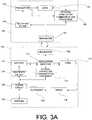
- FIG. 3Aillustrates a detailed block diagram of an exemplary internal stimulator 106 and internal controller 104.
- the internal stimulator 106 and internal controller 104may be implanted in the human body to provide medical treatment to human tissue. Power and control information may be transferred between the internal controller 104 and internal stimulator 106.
- the internal controller 104may include a battery 110, an oscillator and amplifier component 112, an internal controller communications processor 114, a feed component 116, a current sense component 118, a clip-boost component 120, a resonator component 122, a rectifier and filter component 124, a tuning circuit 126, and an antenna 128 for bi-directional telemetry with an external controller 102.
- the antenna 128 in the internal controller 104may be used for bi-directional communication with the external controller 102. Power and control information may be transmitted between the internal controller 104 and the external controller 102 through the antenna 128.
- the internal controller 104may also include a tuning circuit 126.
- the tuning circuitmay include capacitive and inductive elements to tune the antenna 128 to a desired operating frequency to provide efficient communication with the external controller 102.
- the battery component 110may include a rechargeable battery and battery control circuit.
- the battery component 110stores energy received from a primary power source.
- the primary sourcemay be part of or separate from the external controller 102 and provides energy to the battery component 110.
- the primary power sourcemay be a battery located in the external controller or other sources of energy.
- the battery control circuitmay be used to provide energy to the other components in the internal controller 104 via the connection to the oscillator/amplifier component 112.
- the battery control circuitmay also be used to charge the battery as described below. It is understood that the other components in the internal controller 104 may be directly or indirectly connected to the battery for energy transfer.
- the battery component 110may include a non-rechargeable or a rechargeable battery.
- energy in the rechargeable batterymay be replenished when the stored energy is below a certain desired capacity.
- the rechargeable batterymay be charged using indirect recharging methods, such as inductive coupling between the external controller 102 and the internal controller 104.
- the antenna 128may receive energy from the external controller 102.
- the energymay be rectified to single polarity and filtered to a direct current signal using the rectifier and filter component 124.
- the direct current signalmay be used by the recharging circuitry in the battery component 110 to charge the rechargeable battery. It is understood that systems utilizing a non-rechargeable battery will not require the battery to be charged.
- the other methods of recharging the batterymay be used, such as an optical link, laser, or highly directive radio-frequency beam.
- alternative sources of energymay be used to recharging the battery, such as the conversion of kinetic energy into electrical energy. This may be accomplished by converting movement into energy.
- the internal controller 104may be attached to the body may use body movements to spin a rotor that causes a generator to produce an alternating current. The energy in the alternating current may be stored in the battery component 110.
- a thermoelectric generatormay be used to recharge the battery by using heat energy, such as that extracted from heat gradients in the body or that dissipated by the internal controller 104. In this manner, a portion of heat energy which would have otherwise been dissipated to the surrounding tissue is recycled as electrical energy thereby improving the efficiency and safety of the system.
- the oscillator/amplifier component 112may include an oscillator, an amplifier, and connections to the battery component 110, the internal controller communications processor 114, and the feed component 116.
- the oscillator/amplifier 112may be a transistor operating in Class-E mode.
- the oscillator in the oscillator/amplifier component 112may be used to convert the direct current supplied from the battery component 110 into alternating current.
- the amplifier in the oscillator/amplifier component 112may be used to modify the alternating current to achieve the desired current and voltage.
- the oscillator/amplifier component 112outputs the alternating current to the feed component 116.
- the internal controller communications processor 114may include a modulation circuit and connections to the oscillator/amplifier component 112 and the feed component 116.
- the modulation circuit of the internal controller communications processor 114may be used to modulate the carrier signal with the appropriate power and control information intended for the internal stimulator 116.
- the modulationmay occur before the signal enters the oscillator/amplifier component 112 by varying the amplitude and/or frequency of the signal flowing into the oscillator/amplifier component 112.
- the modulationmay occur after the signal flows out of the oscillator/amplifier component 112 by varying the amplitude and/or frequency of the signal flowing into the feed component 116.
- the internal controller communications processor 114may also be used to facilitate communication between the internal controller 104 and the external controller 102.
- the external controller 102may transmit control information to the internal controller 104.
- One type of control informationmay be stimulation parameters for a one or more stimulation sets.
- the stimulation parametersmay include the identity of a particular electrode(s) to control, the pulse amplitude to apply at the selected electrode(s), and the pulse width and frequency of the stimulation that is to be applied, and the pulse pattern to apply at the selected electrode(s).
- control informationmay include other types of information needed to control the various components in the internal controller 104 and/or the internal stimulator 106.
- a usermay input the control information into the external controller 102 for transmission to the internal controller 104, and ultimately, to the internal stimulator 106.
- the external controller 102may store the control information in memory for subsequent transmission to the internal controller 104.
- the external controller 102may initiate a data transmission session. During the data transmission session, a modulated signal containing control information is transmitted from the external controller 102. Once the communication of data is complete, the internal controller 104 and/or external controller 102 will terminate the data transmission session.
- the antenna 128 in the internal controller 104may receive from the external controller 102 the modulated signal carrying control information.
- the internal controller communications processor 114may demodulate the received signal and extract the control information from the modulated signal.
- the internal controller communications processor 114may include a memory location or be coupled to a memory location to store the control information received from the external controller 102. In this manner, control information is transmitted from the external controller 102 to the internal controller 104 only on a periodic basis, such as when the control information stored in the internal controller communications processor 114 must be modified. It is understood that control information for a plurality of different stimulation sets may be stored in the memory location.
- the feed component 116may contain a feed circuit and connections to the oscillator/amplifier component 112, the sense component 118, and the resonator component 122.
- the feed component 116may be wirelessly coupled to the resonator 122, such as by inductive coupling, or may be connected to the resonator component 122 with a wire.
- the feed component 116receives instructions from the internal controller communications processor 114 and drives the resonator 122.
- the feed circuitis tunable such that the resonator component 122 produces a conjugate and optimal match to the oscillator/amplifier component 112 in the internal stimulator 106.
- the conjugate matchmay also be achieved by varying the coupling coefficient between the feed component 116 and the resonator component 122.
- the feed circuitmay be tuned using capacitive and inductive elements.
- the current sense component 118includes current sense circuitry and connections to the feed component 116 and the clip/boost component 120.
- the current sense circuitrysenses the current flowing through the feed component 116 and determines the value of the current.
- the current sense circuitryconveys the determined value of the current to the clip/boost component 120.
- the clip/boost component 120includes power clipping and boosting circuitry and connections to the oscillator and amplifier component 112 and the current sense component 118.
- the clip/boost component 120may be used to control the signal strength at the resonator component 122 such that it remains within a predetermined power range.
- the signal strengthis maintained within the predetermined power range by determining the amount of current driving the antenna and modifying the current via the connection to the oscillator and amplifier component 112.
- the clip/boost component 120may reduce the signal amplitude if the amplitude is higher than the predetermined power range and may boost the signal amplitude if the amplitude is lower than the predetermined power range.
- the resonator component 122includes a resonant structure, such as an antenna, and a tuning circuit.
- the resonant structureproduces electromagnetic fields that may be used to wirelessly transfer power and/or control information from the internal controller 104 to the internal stimulator 106.
- the resonant structuremay be used to convert the current received from the feed component 116 into electromagnetic fields to convey power and control information to the internal stimulator 106.
- the resonant component 122is preferably designed with a high quality factor and tuned to the same resonant frequency as the resonant component 130 to achieve efficient transfer of power.
- the resonator component 122may include tuning circuitry to tune the resonator component 122 to the operating frequency.
- the tuning circuitmay include capacitive and inductive elements.
- control informationmay be periodically transmitted from the internal controller 104 to the internal stimulator 106 and stored in memory at the internal stimulator 106.
- the control informationmay be the control information received from the external controller 102 and stored in memory or may be control information previously stored in memory, in a manner known to those of ordinary skill in the art.
- a modulated signal containing the control informationis generated by the internal controller 104, and preferably by the internal controller communications processor 114. The generated signal containing the control information is transmitted by the resonator 122.
- the internal controller 104 and/or internal stimulatormay terminate the data transmission session.
- the internal stimulator 106may include a resonator component 130, a rectifier and filter component 134, a voltage regulator 136, an internal stimulator communications processor 138 and a load component 140, as illustrated in FIG. 3A .
- the internal stimulator 106may also include a pickup component 132, as illustrated in FIG. 3B .
- the resonator component 130may include a resonant structure, such as an antenna and a tuning circuit.
- the resonant structurereceives an electromagnetic signal from the resonant structure in the internal controller 104 and converts the electromagnetic signal into electric currents. The current may be used to provide power to the internal stimulator 104. In this manner, power is transferred from the internal controller 104 to the internal stimulator 106 and the resulting current is supplied to the other components in the internal stimulator 106.
- the resonant component 130is preferably designed with a high quality factor and tuned to the same resonant frequency as the resonant component 122 to achieve efficient transfer of power from the internal controller 104 to the internal stimulator 106.
- the resonator component 130may include tuning circuitry to tune the resonator component 130 to the operating frequency.
- the tuning circuitmay include capacitive and inductive elements.
- the wireless power transfer between the internal controller 104 and the internal stimulator 106is achieved using a high-Q resonant inductive coupling scheme.
- the high-Q inductive coupling schemeis accomplished using electromagnetic coupling of two or more resonant components 122, 130 tuned to the same resonant frequency. The resonance may be achieved either via self-resonance of the antenna element or via discrete inductive and capacitive elements.
- the resonant components 122,130are tuned to resonate with each other.
- the high-Q resonant inductive coupling schemepermits relatively close to mid-distant placement of the resonant components 122, 130 such that their electromagnetic fields couple.
- the high-Q resonant coupling of the electromagnetic fieldspermits efficient energy transfer between the two resonant components.
- the resonator component 130may be coupled to a pickup component 132.
- the pickup component 132may be wirelessly coupled to the resonator 130, such as by inductive coupling, or may be connected to the resonator component 130 with a wire.
- the pickup component 132may include receiving circuitry and connections to the resonant component 130, the rectifier and filter component 134, and the internal stimulator communications processor 138.
- the pickup component 132may be used to receive current from the resonant component 130 and transfer the current to the other components in the internal stimulator 106.
- the pickup component 132may be tunable so that the resonator component 122 in the internal controller 104 produces a conjugate and optimal match to the pickup component 132. In this manner, power transfer between the internal controller 104 and the internal stimulator 106 is maximized.
- the resonator component 130may be directly connected to the internal stimulator communications processor 138 and the rectifier and filter component 134.
- the rectifier and filter component 134may include a rectifier circuit and filter circuitry and connections to the pickup component 132 and the voltage regulator 136. In systems that do not include the pickup component 132, the rectifier and filter component 134 may be connected directly to the resonator component 130, as illustrated in FIG. 3A .
- the rectifier circuitreceives alternating current from the resonator component 130 via the pickup component 132 and converts the received alternating current into a direct current.
- the filter circuitrymay include a low-pass filter to smooth the current. The resulting direct current may be supplied to other components in the internal stimulator 104, such as the load component 140.
- the rectifier circuitmay be a half-wave rectifier or a full-wave rectifier.
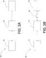
- FIG. 4Aillustrates a circuit schematic for one type of half-wave rectifier 142 that may be used.
- the half-wave rectifier 142includes a single diode 144 connected in series with a coil 146.
- FIG. 4Billustrates a circuit schematic for a non-center tapped full-wave rectifier 148 that may be used in the present system 100.
- the non-center tapped full-wave rectifier 148includes four diodes 150 arranged in a bridge-rectifier configuration.
- FIG. 4Cillustrates a circuit schematic for a center tapped full-wave rectifier 152 that may be used in the system 100.
- the center tapped full-wave rectifier 152includes two diodes 150 with a center-tapped coil 154.
- a half-wave rectifiermay be used for systems with a low voltage requirement and low coupling coefficients. Systems that require high voltage may use a full-wave rectifier or a voltage multiplier. In systems operating at higher frequencies, such as 2 MHz or greater, the diodes illustrated in FIGS. 4A-4C may be replaced with Schottky rectifiers.
- the voltage regulator component 136may include a voltage regulator and connections to the rectifier and filter component 134 and the load component 140.
- the voltage regulatorreceives the direct current from the rectifier and filter component 134 and uses the received current to generate one or more constant voltages. For example, one constant voltage may be supplied to the load component 140 and one constant voltage may be supplied to the internal stimulator communication processor 138.
- the value of the constant voltage(s) supplied to the load component 140 and the internal stimulator communications processor 138depend on the requirements of each of those components.
- the voltage regulatorprevents the load component 140 and internal stimulator communications processor 138 from being damaged due to any fluctuations in the rectified voltage outputted by the rectifier and filter component 134.
- the internal stimulator 106may also include a thermoelectric generator (not shown) used to capture heat energy, such as that extracted from heat gradients in the body.
- the thermoelectric generatoruses the captured heat to generate a voltage which may be used to supplement power received from the internal controller 104. In this manner, a lesser amount of power may be transferred from the internal controller 104 to the internal stimulator 106, while still providing the necessary power to the load 140.
- the internal stimulator communications processor 138may contain signal modulation and demodulation circuitry and connections to the load component 140 and the pickup component 132.
- the internal stimulator communications processor 138may be used to recover any control information received by the resonator component 130 during a data transmission session.
- the recovered control informationmay be stored in memory within the internal stimulator communications processor 138 or in memory coupled to the internal stimulator communications processor 138.
- the control informationmay include stimulation parameters for a one or more stimulation sets that are applied by the stimulation electrodes 158.
- the stimulation parametersmay include the identity of a particular electrode(s) to control, the pulse amplitude to apply at the selected electrode(s), and the pulse width and frequency of the stimulation that is to be applied, and the pulse pattern to apply at the selected electrode(s).
- the load component 140is connected to the voltage regulator component 136 and the internal stimulator communications processor 138 to perform a specific task, such as providing stimulation to tissue.
- the load component 140may include a stimulus driver 156 coupled to stimulating electrodes 158 to provide stimulation to tissue 160.
- the load component 140may also include a feedback circuit for detecting sensory information.
- the sensory informationmay include, for example, diagnostic information such as tissue resistance, electro-physiological actions such as neural and myocardial action potentials, and other electrical and non-electrical characteristics.
- the feedback circuitmay detect the sensory information and transmit the sensory information to the internal stimulator communications processor 138.
- the internal stimulator communications processor 138may store the sensory information in a memory location. The memory location may be in the internal stimulator communications processor 138 or a memory location coupled to the internal stimulator communications processor 138.
- the sensory informationmay be periodically transmitted from the internal stimulator 106 to the internal controller 104 stored in a memory location at the internal controller 104.
- either the internal stimulator 106 or internal controller 104may initiate a data transmission session.
- a modulated signal containing the control informationis generated by the internal stimulator 106, and preferably by the internal stimulator communications processor 138.
- the generated signal containing the sensory informationis transmitted by the resonator component 130.
- the internal controller 104may receive the signal via the resonator component 122 and demodulate the signal to recover any sensory information received during the data transmission session.
- the recovered control informationmay be stored in memory within the internal controller communications processor 114 or in memory coupled to the internal controller communications processor 114.
- the internal controller 104may transmit data, such as sensory information received from the internal stimulator 106, to the external controller 102.
- datasuch as sensory information received from the internal stimulator 106
- either the internal controller 104 or external controller 102may initiate a data transmission session.
- a modulated signal containing the sensory informationis generated by the internal controller 104, and preferably by the internal controller communications processor 114.
- the generated signal containing the sensory informationis transmitted by the antenna 128.
- the external controller 102detects the signal transmitted from the antenna 128 and demodulates the signal to extract the sensory information. Once the communication of sensory information is complete, the internal controller 104 and/or external controller 102 may terminate the data transmission session.
- modulation schemesmay be implemented to facilitate wireless communication of data, including control information and sensory information, between the internal controller 104 and the external controller 102 and also between internal controller 104 and the internal stimulator 102.
- modulation schemesincluding control information and sensory information, between the internal controller 104 and the external controller 102 and also between internal controller 104 and the internal stimulator 102.
- frequency-shift keying/frequency modulationFSK/FM
- PWMpulse width modulation
- AMamplitude modulation
- OLKOn Off Keying
- an OOK modulation schemeis used to facilitate communication of control information between the internal controller 104 and the internal stimulator 106.
- a fixed number of cycles at the operating frequency ⁇will denote a "1" or a "0" when the signal is ON or OFF, respectively.
- the basic operation of the OOK modulation schemewill now be described below.
- a continuous signal at ⁇is generated by the internal controller 104 which magnetically couples to the resonator component 130 in the internal stimulator 106 and subsequently the load component 140 for operation of the internal stimulator 106.
- a pre-set word patternis generated to indicate the beginning of communication of control information.
- a bit sequenceis generated at the internal controller 104.
- the bit sequenceidentifies a particular electrode to control, the pulse amplitude to apply at the selected electrode, and the pulse width and frequency of the stimulation that is to be applied.
- the bit sequenceis subsequently transmitted from the internal stimulator 104 to the internal stimulator 106 and decoded by an internal stimulator communications processor 138. Once the communication of control information is complete, the internal controller 104 will generate a signal at frequency ⁇ until further communication is required.
- FIG. 6illustrates a schematic of the tissue 160 that may be stimulated using the stimulating electrodes 158.
- the tissue 160may be any type of human tissue, such as, for example, connective tissue, dural tissue, visceral muscle tissue, skeletal muscle tissue, cardiac muscle tissue, neural tissue, epithelial tissue, bone tissue, cerebrospinal fluid, or any other type of human tissue known to those of ordinary skill in the art. Additionally, although the example provided herein discuss human tissue, the present system and method may also be used with other animal tissue known to those of ordinary skill in the art.
- the stimulated tissue 100inherently includes a resistance 159 and capacitance 161. The values of the resistance 162 and capacitance 164 may be determined based on the appropriate power and stimulation necessary to provide the appropriate medical treatment.
- the stimulating electrodes 158provide a stimulus to the stimulated tissue 160.
- the tissue 160 that is stimulatedmay be A-Beta neural fibers, which are responsible for gross touch, vibration, and proprioception functions.
- the maximum diameter of such fibersis generally 15 ⁇ m. It is preferable that the tissue fibers which are to be stimulated have a diameter of at least 10.7 ⁇ m, however, it is contemplated that any fibers having a diameter of less than 10.7 ⁇ m can be stimulated.
- the A-Beta neural fibersare located in the dorsal column in the spinal cord, approximately 0.20-0.25 mm below the pia mater.
- the tissue 110 that is to be stimulatedincludes up to approximately 65 fibers in the dorsal column, which innervates up to approximately 12 dermatomes. It is preferred that 4 to 5 fibers are specific to a targeted dermatome. It is also contemplated that the stimulation of only 1 fiber may achieve paresthesia.
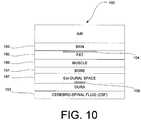
- FIG. 7Aillustrates an anatomical model of tissue 160 that may be stimulated by the stimulating electrodes 158.
- the stimulated tissue 160is neural and surrounding tissue of the spinal column 162 and is modeled as 3 concentric cylinders 164, 166, 168.
- the spinal column 162includes an outer insulating vertebral bone and epidural fat 164, a middle conductive cerebrospinal fluid 166, and a spinal cord 168.
- the transverse resistance of the outer insulating vertebral bone and epidural fat 164 and spinal cord 168 of the spinal column 162is greater than the longitudinal resistance of the outer insulating vertebral bone and epidural fat 164 and spinal cord 168 of the spinal column 162.
- the transverse resistance and the longitudinal resistanceare substantially greater than the resistance provided by the cerebrospinal fluid 166.
- tissue resistivity and normalized valuesare provided in the Table 1: Table 1: Approximate Tissue Resistivity (R) and Normalized Values (R norm ) Structure R( ⁇ .cm) R norm Spinal gray matter 435 7.4 Spinal white matter Transverse 1205 20.4 Longitudinal 167 2.8 Cerebrospinal fluid 59 1.0 Epidural fat 2500 42.4 Vertebral bone 2500 42.4
- the stimulating electrodes 158are positioned to electrically contact the middle conductive cerebrospinal fluid 166.
- the relatively low resistance of the cerebrospinal fluid 166 as compared to the transverse and longitudinal resistanceallows a greater percentage of current to flow through the cerebrospinal fluid 166 as compared to the other portions of the spinal cord. It is preferable that approximately 90% of the current discharged from the stimulating electrodes 158 flow through the cerebrospinal fluid 166 and 10% of the current flow through the outer insulating vertebral bone and epidural fat 164 and spinal cord 168 of the spinal column 162.
- the current discharged from the stimulating electrodes 158preferably stimulates five to six DC neurons, however it is understood that typically, only one of the neurons innervates the dermatome of interest.
- a current density mode numerical modelis illustrated in FIG. 7B . Based on the numerical model, it is understood that the current is substantially within the cerebrospinal fluid 134.
- the stimulating electrodes 158provide electrical stimulation to the tissue 160.
- the stimulus drivers 156, regulator component 136 and internal stimulator communications processor 138operate to provide a pulsed current to the stimulating electrodes 158.
- one objective of the electrical stimulation provided to the tissue 160is to relieve pain for the entire area in which a patient is experiencing pain.
- Another objectiveis to focus the electrical field created by the stimulation on the appropriate section of the dorsal column.
- the electric fieldis focused on the spinal cord midline; for unilateral pain the electric field is focused up to 1 mm lateral to the midline, and for segmental pain, the electric field is focused further than 1 mm lateral to midline so as to stimulate a specific dorsal root. It is also contemplated that other distances lateral to the midline may used to provide stimulation for unilateral or segmental pain. Another objective of the stimulation may be to stimulate the A-beta fibers specific to the dermatome where the patient is experiencing pain and to also overcome the paresthesia threshold but not the discomfort threshold.
- the stimulus parametersinclude at least a therapeutic range and pulse parameters.
- the pulse parametersmay include a current pulse width of 30-500 ⁇ s, a pulse frequency of 10-1200 Hz, a pulse current of 0.1-25 mA, and a tissue impedance of 1k ⁇ .
- Other values for the pulse width, pulse frequency, current pulse width, and tissue impedancemay be utilized without departing from the scope of the present teachings.
- other pulse parameterssuch as polarity (i.e., monophasic or biphasic), may be provided.
- the maximum level of power applied to a stimulation site having a tissue impedance equal to 1 k ⁇is 0.39 Watts.
- a single stimulation setmay be used to provide 0.39 Watts to the tissue.
- a stimulation set of eightmay be used to provide 0.39 Watts to the tissue.
- the tissue impedancemay be different and may affect the values of the amplitude, current pulse width, frequency. It is also understood that the number of stimulation sets and the desired power level applied to the tissue may be varied. These variations may also affect the values used for the amplitude, current pulse width, frequency. For example, in one embodiment, the tissue impedance may be 524 ⁇ . If the same values are used for the amplitude, current pulse width, frequency, and stimulation sets provided in tables 2 and 3, the power is reduced to 0.21 Watts.
- the stimulating electrodes 158apply stimulation to the tissue 160 according to the stimulus parameters.
- the stimulating electrodes 106may be percutaneous electrodes, paddle electrodes, or any other electrodes that may be used to provide stimulation to tissue 160.
- the stimulating electrodes 106may also be electrodes that provide stimulation using magnetically induced currents. It is understood that other types of electrodes known to those having ordinary skill in the art may also be used.
- percutaneous electrodestwo to eight electrodes arranged in series may be used. It is also contemplated that more than eight electrodes may be used.
- the percutaneous electrodesmay also be placed adjacent to one another for parallel stimulation.
- the percutaneous electrodesmay be implanted using a needle or any other methods known in the art.
- paddle electrodesWhen paddle electrodes are used, it is preferred to use between two and sixteen electrodes arranged in series or parallel. It is understood that more than sixteen electrodes may be used.
- the paddle electrodesmay be implanted via laminectomy, using a needle, or any other methods known to those of ordinary skill in the art.
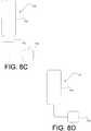
- FIG. 8Aillustrates one example of an internal stimulator 106 in the form of a paddle-type lead 169.
- the paddle-type lead 169may include an array of stimulus electrodes 158 encased in an electrode casing 170.
- the electrode casing 170may be formed of highly durable bio-compatible materials, such as silicone or PDMS.
- the paddle-type lead 169may also include a resonator component 130 that is integrated into the paddle-type lead 169.
- the pickup component 132may also be integrated in the paddle-type lead 169.
- Additional circuitry, such as the rectifier and filter component 134, the voltage regulator component 136, and the internal stimulator communications processor 138may be contained in a housing 172.
- FIG. 8Billustrates another example of an internal stimulator 106 in the form of a paddle-type lead 171.
- the paddle-type lead 171 illustrated in FIG. 8Bis similar to the paddle-type lead 169 illustrated in FIG. 8A .
- the paddle-type lead 171 illustrated in FIG. 8B leadmay include an array of stimulus electrodes 158 that encased in an electrode casing 170.
- the electrode casing 170may be formed of highly durable bio-compatible materials, such as silicone or PDMS.
- the resonator component 130, the pickup component 132, the rectifier and filter component 134, the voltage regulator component 136, and the internal stimulator communications processor 138may be contained in a housing 172.
- FIG. 8Cillustrates an example of an internal stimulator 106 in which the paddle-type lead 173 is displaced a short distance from a housing 175 that contains the resonant component 130 and/or the pickup component 132.
- the paddle-type lead illustrated in FIG. 8C leadmay include an array of stimulus electrodes 158 that encased in an electrode casing 170.
- the electrode casing 170may be formed of highly durable bio-compatible materials, such as silicone or PDMS.
- the rectifier and filter component 134, the voltage regulator component 136, and the internal stimulator communications processor 138may be contained in a housing 172 that is adjacent to the paddle-type lead 173.
- the resonator component 130 and the pickup component 132may be displaced a short distance from the paddle-type lead and connected to the circuitry with a lead wire.
- FIG. 8Dillustrates another example of an internal stimulator 106 in which the paddle-type lead 177 is displaced a short distance from a housing 175 that contains the resonant component 130, the pickup component 132, the voltage regulator component 136, and the internal stimulator communications processor 138.
- the paddle-type lead 177 illustrated in FIG. 8D leadmay include an array of stimulus electrodes 158 that encased in an electrode casing 170.
- the electrode casing 170may be formed of highly durable bio-compatible materials, such as silicone or PDMS.
- the rectifier and filter component 134, the voltage regulator component 136, and the internal stimulator communications processor 138, resonator component 130 and pickup component 132may be displaced in a housing 175 a short distance from the paddle-type lead 177 and connected to the paddle-type lead with a lead wire.
- FIGS. 9A-9Billustrate the location of the internal controller 104 and internal stimulator 106 used for spinal cord stimulation in the human body 179.
- FIG. 9Aillustrates a coronal cross-section
- FIG. 9Billustrates an enlarged sagittal cross-section of a portion of the posterior region 181 of a human body 179 showing the internal controller 104 and internal stimulator 106.
- the internal controller 104is placed under the skin 183, and looking into the coronal plane, may lie in either half of the body, the axis being the spinal column 185 (refer to FIG. 9A ).
- the internal stimulator 106may be in the epidural space 187, either as percutaneous leads, as a paddle-type lead (as illustrated in FIGS. 8A-8D ), or as any other type of stimulating mechanism, as described herein.
- the paddleIn case of paddle-type lead, the paddle may conform to the geometry of the dura, and may be fed by a lead.
- the lead (for paddles), leads (for percutaneous electrodes), and leads of any other type of stimulating mechanismmay originate at the resonator component 130.
- the resonator 130 at the internal stimulatorhave low loss, high inductance and be matched to the subsequent circuit elements in the internal stimulator 104, such as the rectifier and filter component 134, the voltage regulator 136, the internal stimulator communications processor 138 and the load component 140.
- the present system and methodmay be used to transfer power is in the near-field.
- the distance between the resonant component 122 in the internal controller 104 and the resonant controller 130 in the internal stimulatorbe within the near-field region at the operating frequency.
- the appropriate wavelength of the electromagnetic field ( ⁇ Effective ) used in the systemis based on the distance (D) between the two resonant components 122, 130 according to the following equation: D ⁇ ⁇ Effective 2 ⁇
- the amount of power harnessed at the resonant component 130is based, in part, on the frequency of operation.
- FIG. 10Aillustrates a simplified layered tissue model 180 from the posterior region 181 of the human body 179. It is noted that the tissue model illustrated in FIG. 10 is an approximation to characterize the medium and is not to scale. As noted above, it is preferred that the internal controller 104 be placed just under the skin 183, in the fat 185, and that the stimulating electrodes 158 of the internal stimulator 106 be placed in the epidural space 187. The tissue regions between internal controller 104 and the internal stimulator include a portion of the fat region 185, the muscle region 189, and the bone region 191.
- the frequency of operation in the present examplemay be approximately between 135 KHz and 150 KHz or, in the alternative, be between 2 MHz and 30 MHz. It is understood that frequency of operation may be between 150 KHz and 2 MHz or greater than 30 MHz.
- the resonator component 130may be designed to be housed in a package that is suitable for being implanted in a human body.
- a package designed to be implanted in a human bodyis illustrated in FIG. 11 .
- the package 192 designed to house the resonator component 130may have a volume of approximately 0.8-1cms by 0.8-1 cm by 0.3 cms.
- the package 192 for the resonant component 130may also include approximately a 1 mm boundary on each side.
- the total volume available to package the resonant component 130is 1-1.2 cms by 1-1.2 cms by 0.5 cms. It is understood that a greater volume may be used to house the resonator component 130 without departing from the teachings of the present example.
- the available volumebe utilized to maximize the quality factor of each of the resonant components 122, 130.
- the quality factor of each resonant component 122, 130is greater than 100.
- a quality factor of greater than 100may be achieved based on the configuration and materials used to design the resonant component.
- the configuration of the resonant components 122, 130may be a squircle, a square, circular, rectangular or triangular planar spiral; a square, circular, rectangular, or triangular planar figure-of-eight; a squircle, a square, circular, rectangular, or triangular solenoid figure-of-eight; or a squircle, square, circular, rectangular, or triangular multi-layer solenoid. It is also contemplated that the resonant antennas 122, 130 may also be configured as two or more orthogonal antenna in any of the configurations described above. Other configurations known to those of ordinary skill may also be utilized.
- FIG. 12A - FIG. 12Dillustrate examples of different resonant component configurations that may be designed to fit in the available volume.
- the resonant component structures illustrated in FIG. 12A - FIG. 12Dmay have conductors that are thin wire filaments but it is understood that wires may be of varying thicknesses, such as, for example between 1 ⁇ m and 3 mm. It is also understood that the cross-section could be one of a plurality of shapes known to those of ordinary skill in the art, such as, for example, circular, rectangular, or triangular.
- FIG. 12Aillustrates a resonant component in a solenoid configuration 195.
- FIG. 12Billustrates a resonant component in a conformal solenoid configuration 197.
- the resonant component in a conformal solenoid configurationmay take the form of a circular solenoid or a circular or rectangular spiral.
- FIG. 12Cillustrates a resonant component in a multi-layer solenoid configuration 199. Although only two layers are illustrated in FIG. 12C , it is understood that any number of layers may be used.
- FIG. 12Dillustrates a resonant component in a square spiral configuration 201. It is understood that other spiral configurations, such as a rectangular or square shape may be utilized.
- FIG. 12Eillustrates a resonant component having an orthogonally oriented coil configuration 203. In such a configuration, one or more coils are orthogonally oriented. The coils may take any of the shapes described in FIGS 12A-12D .
- the orthogonally oriented configurationmay be used to reduce the dependence of the induced voltage on the orientation of the resonator components 122, 130. It is understood that the resonant components described herein may be self-resonant or be resonant by the addition of capacitive and/or inductive elements.
- the cross-sectional shape of the wire that is used to form the resonant component 122, 130may be circular, square, rectangular, or triangular.
- the wirehas a relatively small diameter, or height relative to the width of the wire, and may be on the order of twice the skin-depth at the operating frequency.
- FIG. 13A - FIG. 13Fillustrate cross-sections of wires that may be used in the design of the resonant component 122, 130.
- FIG. 13Aillustrates a wire having a circular cross section 205.
- FIG. 13Billustrates a wire having a rectangular cross section in the form of a square 207.
- FIG. 13Cillustrates a wire having a thin rectangular cross section 209.
- FIG. 13Dillustrates a wire having an elliptical cross section 211.
- FIG. 13Eillustrates a cross section of a litz wire 213.
- FIG. 13Fillustrates a cross section of a copper tube 215.
- the wiremay be copper, gold, silver-coated copper, silver-coated gold, or any other conductor.
- a wire having a thin rectangular cross sectionit may be preferable to use a wire having a thin rectangular cross section, a wire having an elliptical cross section, a litz wire, or a copper tube for applications in which the frequency is greater than 100 kHz.
- the quality factor of the resonant component 122, 130is based, in part, on the number of layers and the metal thickness and metal strip width of the wire in each layer.
- Each layermay be a single strip of metal having a metal thickness and metal strip width.
- FIG. 14Aillustrates cross-section of a resonant component having a first layer 217 and a second layer 219.
- An insulating material 223separates the first layer 217 from the second layer 219.
- the first layer 217 and second layer 219are connected with vias 221 which traverse the insulating material 223.
- the metal thickness of the first layer 217is identified by line A-A and the metal strip width of the first layer 219 is identified by line B-B.
- the metal thickness of a layermay be approximately twice the skin-depth. Each layer in a turn will have substantially the same metal thickness and metal strip width. A higher quality factor may be achieved using multiple layers for a single turn of coil. If additional layers are added to a turn of the coil, the additional layers include insulating material and are electrically connected to the other layers in that turn using vias through the insulating material. It is understood that by varying the number of turns, the metal thickness, and metal strip width, a higher quality factor may be achieved.
- the resonant component 122, 130may be a single turn coil having multiple layers, as illustrated in FIG. 14B .
- the single turn coilincludes a single turn and may include a metal thickness of approximately 0.03 mm, a metal strip width of approximately 1.75 mm, and an outer radius of approximately 5 mm.
- the coilmay have between 10 and 60 layers; however it is understood that the coil may have less than 10 or more than 60 layers in order to achieve a high quality factor.
- the quality factor at 27 MHzis approximately 242.
- the quality factoris increased to approximately 400. It is also understood that metal strip width may be increased to achieve a higher quality factor.
- the resonant component 122, 130may be coil having multiple turns and multiple layers, as illustrated in FIG. 14C .
- the coilmay include two turns and may include a metal thickness of approximately 30 ⁇ m, a metal strip width of approximately 1.75 mm, and an outer coil radius of approximately 5 mm.
- the illustrated coilincludes two turns, it is understood that the coil may include more than two turns.
- the coilpreferably has between 10 and 60 layers; however it is understood that the coil may have less than 10 or more than 60 layers in order to achieve a higher quality factor. For example, for a ten layer two turn coil having a metal thickness of 30 ⁇ m and a metal strip width of 1.75 mm, the quality factor at 27 MHz is approximately 740. It is understood that metal strip width may be increased to achieve a higher quality factor.
- the designs shown in FIGS. 14B and 14Cmay be modified by using a thinner metal strip thickness, such as for example, approximately 50 ⁇ m.
- the metal thicknessmay be approximately 30 ⁇ m and the outer coil radius may be approximately 5 mm.
- the coilhas 15 layers, however it is understood that the coil may have more layers in order to achieve a high quality factor. It is also understood that the number of turns may be increased or decreased in order to achieve a high quality factor.
- the resonant component 122, 130be resonant.
- the resonant component 122, 130may be made resonant with the addition of a capacitor.
- the added capacitormay be a high quality factor capacitor.
- the rectifier and filter component 134, voltage regulator 136, internal stimulator communications processor 138, and load component 140comprise electronics and active and passive circuits that are powered by the inductively coupled link between the resonant component 122 and the resonant component 130, as described above.
- the resonant component 130be conjugate matched to the rectifier and filter component 134, voltage regulator 136, internal stimulator communications processor 138, and load component 140.
Landscapes
- Engineering & Computer Science (AREA)
- Power Engineering (AREA)
- Health & Medical Sciences (AREA)
- Physics & Mathematics (AREA)
- Computer Networks & Wireless Communication (AREA)
- Electromagnetism (AREA)
- Signal Processing (AREA)
- Manufacturing & Machinery (AREA)
- Veterinary Medicine (AREA)
- Biomedical Technology (AREA)
- Nuclear Medicine, Radiotherapy & Molecular Imaging (AREA)
- Radiology & Medical Imaging (AREA)
- Life Sciences & Earth Sciences (AREA)
- Animal Behavior & Ethology (AREA)
- General Health & Medical Sciences (AREA)
- Public Health (AREA)
- Microelectronics & Electronic Packaging (AREA)
- Acoustics & Sound (AREA)
- Neurology (AREA)
- Neurosurgery (AREA)
- Orthopedic Medicine & Surgery (AREA)
- Cardiology (AREA)
- Heart & Thoracic Surgery (AREA)
- Coils Or Transformers For Communication (AREA)
- Electrotherapy Devices (AREA)
- Near-Field Transmission Systems (AREA)
Description
- The present subject matter relates to a system and method for energy transfer between two or more devices, and more specifically, to a system and method for the transfer of power and/or data between two or more devices in near-field communications.
- In recent years, the use of wireless energy transfer or wireless power transmission has been used to transfer electrical energy from a power transmitter (such as a source) to a receiver without the use of interconnecting wires. Wireless energy transfer is useful in cases where instantaneous or continuous energy transfer is needed where interconnecting wires are inconvenient or hazardous. Typically, wireless energy transfer involves the use of antennas which are used to transmit and/or receive power and data using time-varying currents, such as alternating currents. Such systems are generally referred to as inductively coupled systems.
- The efficiency of energy transfer between two devices in an inductively coupled system is based on the quality factor of the antenna in transmitter (Q1), the quality factor of the antenna in the receiver (Q2), and the coupling coefficient between the two antennas (κ). The efficiency of the energy transfer varies according to the following relationship:

- The quality factor represents the rate of energy loss relative to the stored energy of the antenna. A higher quality factor indicates a lower rate of energy loss relative to the stored energy of the antenna. Conversely, a lower quality factor indicates a higher rate of energy loss relative to the stored energy of the antenna. The coupling coefficient expresses the degree of coupling that exists between two antennas. The value of the coupling coefficient may be based on the proximity of the antennas, the orientation of each antenna relative to the other antenna, and the environment in which the antennas are located. A higher coupling coefficient may be achieved by placing the antennas closer to one another, by orientating each antenna such that electromagnetic fields generated by the antenna are aligned, or removing environmental elements that reduce the strength of the generated electromagnetic fields.
- Although the quality factor may increase the efficiency of an inductively coupled system, the quality factor inversely affects the bandwidth that is available to transmit data. Specifically, the bandwidth available to transmit data (BW) is inversely proportional to the quality factor of an antenna and varies according to the following relationship:

- As a result, a higher quality factor reduces the available bandwidth for data transmission. Given the mathematical relationship between the bandwidth and quality factor, data-intensive systems that require significant bandwidth will require that the quality factors of the transmitting and receiving antennas be decreased. The low quality factor of the antennas in these systems requires a high coupling coefficient in order to increase the efficiency of energy transfer between the transmitter and the receiver in the system. However, often times, it may not be possible to increase the coupling coefficient due to the various environmental constraints.
- Recently, implantable tissue stimulation systems have been developed to provide electrical stimulation for the treatment and management of chronic intractable pain, heart arrhythmia, and other medical conditions in which stimulation may be beneficial. Generally, these systems include an implantable controller device and at least one stimulating electrode for providing electrical stimulation to tissue. The implantable controller device (such as an implantable pulse generator) controls the stimulation that is provided to the tissue. The implantable controller device may control the stimulation by providing continuous stimulation control signals to the stimulating electrodes that control the pulse amplitude, pulse width and frequency, and pulse pattern applied by the stimulating electrode. Wire leads originate from the implantable controller device and terminate in stimulating electrodes at the stimulation site. One disadvantage of current tissue stimulation systems is the formation of scar tissue around the lead wires leading to the breakage and/or migration of the lead wires due to stress and strain caused by body movement. An improvement over these existing systems would be to remove the wires and design a system in which the implantable controller device could wirelessly provide power and stimulation control signals to the stimulating electrodes.
- Currently available implantable tissue simulation systems also require high-data transfer rates because the implantable controller device controls the stimulation by providing continuous signals to the stimulating electrodes. As noted above, in wireless communications, data intensive systems require substantial bandwidth. In designing such systems, the quality factors of the transmitting and receiving antennas must be reduced in order to achieve the necessary bandwidth required for data transmission. Thus, in order to achieve high efficiency systems with a low quality factor; it is necessary to have a high coupling coefficient between the transmitter and the receiver in the system. However, it may not be possible to achieve a high coupling coefficient in certain environments.
- Thus, there currently exists a need for an improved system and method for energy transfer between two more or more devices in a system via high quality factor resonant inductive coupling.
EP 1 609 503 A1 describes an implantable medical device system advantageously utilizes low frequency, e.g., about 1 - 100 kHz, transcutaneous energy transfer (TET) for supplying power from an external control module to an implantable medical device, avoiding power dissipation through eddy currents in a metallic case of an implant and/or in human tissue, thereby enabling smaller implants using a metallic case such as titanium and/or allowing TET signals of greater strength, thereby allowing placement more deeply within a patient without excessive power transfer inefficiencies.- The teachings herein alleviate one or more of the above noted problems. One aspect of the present teaching is a system for energy transfer between a transmitting unit and a receiving unit as defined in claim 1. Further preferred embodiments are set forth in the dependent claims.
- Additional advantages and novel features will be set forth in part in the description which follows, arid in part will become apparent to those skilled in the art upon examination of the following and the accompanying drawings or may be learned by production or operation of the examples. The advantages of the present teachings may be realized and attained by practice or use of various aspects of the methodologies, instrumentalities and combinations set forth in the detailed examples discussed below.
- Yet another aspect of the present teachings is a method for providing electrical stimulation to human tissue in a system having a first implantable device having a first resonator having a first resonant frequency and a high quality factor and a second implantable device having a second resonator inductively coupled to the first resonator wherein the second resonator having a second resonant frequency and a high quality factor. The method may comprise the steps of detecting an electromagnetic field generated by the first resonator; generating an induced current, wherein the induced current is an alternating current; generating a stimulation current based on the induced current; and, applying the stimulation current to human tissue. The stimulation current may be generated based on at least one of a pulse amplitude, a pulse width and frequency, and a pulse pattern. The method may also include the steps of detecting a modulated time-varying signal generated by the first resonator, wherein the signal comprising at least one set of control information periodically; demodulating the time-varying signal to extract the control information; and storing the at least one set of control information in the memory location in the second implantable device. The method may also include the steps of detecting sensory information; and generating a modulated time-varying signal comprising at least a portion of the sensory information.
- Another aspect of the present teachings is a resonator for use in a system for energy transfer between a first device and a second device. The resonator may include a coil having an operating frequency, the coil having at least one turn wherein the at least one turn has a plurality of layers further wherein each layer in the plurality of layers is electrically connected to the other layers in the plurality of layers. Each layer may include an insulator for insulating the layer from the other layers. Each layer in the plurality of layers may be electrically connected to the other layers using at least one via. The lay may include a thickness substantially equal to twice the skin-depth at the operating frequency.
- Additional advantages and novel features will be set forth in part in the description which follows, and in part will become apparent to those skilled in the art upon examination of the following and the accompanying drawings or may be learned by production or operation of the examples. The advantages of the present teachings may be realized and attained by practice or use of various aspects of the methodologies, instrumentalities and combinations set forth in the detailed examples discussed below.
- The drawing figures depict one or more implementations in accord with the present teachings, by way of example only, not by way of limitation. In the figures, like reference numerals refer to the same or similar elements.
FIG. 1A illustrates an example of a high-level block diagram of a near-field energy network;FIG. 1B illustrates an example of a high-level block diagram of a near-field energy network;FIG. 2A illustrates an example of a high-level block diagram of a system for stimulating human tissue;FIG. 2B illustrates an example of a high-level block diagram of a system for stimulating human tissue;FIG. 3A illustrates an example of a block diagram for internal stimulator and an internal controller;FIG. 3B illustrates an example of a block diagram for internal stimulator and an internal controller;FIG. 4A illustrates an example of a circuit schematic for one a half-wave rectifier;FIG. 4B illustrates an example of a circuit schematic for a non-center tapped full-wave rectifier;FIG. 4C illustrates an example of a circuit schematic for a center tapped full-wave rectifier;FIG. 5 illustrates an example of a block diagram for a portion of the internal stimulator;FIG. 6 illustrates an example of a schematic of the tissue that may be stimulated using the stimulating electrodes;FIG. 7A illustrates an example of an anatomical model of the tissue that may be stimulated using the stimulating electrodes;FIG. 7B illustrates a current density mode numerical model;FIGS. 8A-8D illustrate examples of various internal stimulators;FIG. 9A illustrates a coronal cross-section of the human body;FIG. 9B illustrates an enlarged sagittal cross-section of a portion of the posterior region of a human body;FIG. 10 illustrates an example of a simplified layered tissue model from the posterior region of the human body;FIG. 11 is an illustration of an example of the total volume available to package a resonant component;FIGS. 12A-12D illustrate examples of different resonant component configurations that may be designed to fit in the available volume illustrated inFIG. 11 ;FIGS. 13A-13F illustrate examples of cross-sections of wires that may be used in the design of a resonant component;FIG. 14A illustrates a cross-section of one example of a resonant component; and,FIGS. 14B-14C illustrate examples of resonant component configurations.- In the following detailed description, numerous specific details are set forth by way of examples in order to provide a thorough understanding of the relevant teachings. However, it should be apparent to those skilled in the art that the present teachings may be practiced without such details. In other instances, well known methods, procedures, components, and/or circuitry have been described at a relatively high-level, without detail, in order to avoid unnecessarily obscuring aspects of the present teachings.
- The various technologies described herein generally relate to a system and method for energy transfer between two or more devices via high quality factor (Q) resonant inductive coupling, and more specifically, to a system and method for the transfer of power and/or data between two or more devices in near-field communications via high-Q resonant inductive coupling.
FIG. 1A illustrates a high-level block diagram of a near-field energy network 10. Thenetwork 10 includes a plurality of devices 11a-d (generally referred to as device 11). Each device 11 may include a transceiver. The transceiver may include a transmitting unit 12a-d and a receiving unit 14a-d for wireless communications. Although each transceiver may include a transmitting unit 12 and a receiving unit 14, it is understood that the transceiver may comprise only a transmitting unit 12 or only a receiving unit 14. Further, it is understood that the transmitting unit 12 and the receiving unit 14 in the transceiver may share certain or all circuit elements or may have separate and distinct circuit elements. Further, as will be described in greater detail herein, the transmitting unit 12 and/or receiving unit 14 may be coupled to aload 16. Theload 16 may comprise of components within the device 11, outside the device 11, or a combination of components within and outside the device 11.- Each transmitting unit 12 includes a transmitting antenna 13. The transmitting antenna 13 has a resonant frequency ωs and preferably has minimal resistive and radiative losses. The
load 16 may include driver circuitry to generate signals to drive the transmitting antenna 13. Based on the received signals, the transmitting antenna 13 may produce a near-field in all directions (omni-directional) or may produce a near-field targeted towards a specific direction (directional). The targeted near-field may be produced through shielding, such as by ferrite materials. Of course, it is understood to those skilled in the art that other materials may be used to provide targeted near-fields. - Each receiving unit 14 includes a receiving antenna 15. A single antenna may be used for both the receiving antenna 15 and the transmitting antenna 13 or a separate antenna may be used for the receiving antenna 15 and the transmitting antenna 13. Each antenna 13, 15 has a resonant frequency (referred to as ωa-ωd). If separate transmitting and receiving antenna are used, it is preferred that the resonant frequency of the receiving antenna 15 is equal to the resonant frequency of the transmitting antenna 13.
- When a receiving unit 14 of one device 11 (e.g., receiving unit 14b) is placed in the near-field of the transmitting unit 12 of another device 11 (e.g., transmitting unit 12a), an electromagnetic field generated by the transmitting unit 12a will interact with the receiving unit 14b. When the resonant frequency ωa of receiving unit 14a is the same as the resonant frequency ωs of transmitting unit 12a, the electromagnetic field generated by the transmitting unit 12a will induce an alternating current within receiving unit 14a. The induced alternating current may be used to power the
load 16b connected to receiving unit 14b or transmit data from the transmitting unit 12a to receiving unit 14b. The alternating current may also be used to charge a power storage device, such as a battery, in theload 16b. Any number of receiving units 14 having resonant frequencies equal to ωs may be added to the near field and draw energy from transmitting unit 12 if the resonance frequency of the transmitting antenna 13 is not significantly altered due to the loading effect on the receiving units 14. Preferably, the transmitting antenna 13 and receiving antenna 15 are designed to have high quality factors to achieve efficient energy transfer between devices 11. The transmitting antenna 13 and receiving antenna 15 may have quality factors greater than 100. The quality factors may also be greater than 350. Preferably, the quality factors are greater than 600. It is understood that traditional inductively coupled systems utilize antennas with a quality factor around 30. - In addition to transferring power, the energy transfer may be used to transfer data from a transmitting unit 12 in one device (e.g., transmitting unit 12a) to a receiving unit 14 in another device (e.g., receiving unit 14b). As will be described herein, the receiving units 14 may be designed to receive data, transmit data, or receive and transmit data. If the receiving unit 14 is designed to receive and transmit data, the receiving unit 14 may have a shared antenna 13 for receiving and transmitting, or separate dedicated antennas 13, 15 for transmitting and receiving data. The receiving units 14 may also be designed transfer data, transfer power, or transfer data and power. If the receiving unit 14 is designed to transfer power and data, each receiving unit 14 may use any combination of sending data, receiving data, sending power, and/or receiving power. It is also contemplated that each receiving unit 14 may use a shared antenna for data and power transfer, or each receiving unit 14 may have a separate dedicated antennas for power transfer and data transfer.
- When a receiving unit 14 (e.g., receiving unit 14b) is placed within the near-field of the transmitting unit 12 (e.g., transmitting unit 12a) and both the receiving unit 14b and the transmitting unit 12a resonate at the same frequency and have antennas having high quality factors, energy will efficiently transfer from the transmitting unit 12a to the receiving unit 14b. It is understood that if additional receiving units 14c-14d are placed in the near-field, the additional receiving units 14c-14d will also resonate at the same frequency and draw energy from transmitting unit 12a in the form of an induced alternating current. The receiving units 14a-14d may include a transducer which may use the induced alternating current to store energy in a power storage device, such as battery or capacitor. Alternatively, the transducer may use induced alternating current to directly power electronic components within the receiving unit 14.
- It is understood that it may not be possible to place all receiving units 14 within the near-field of the transmitting unit 12. As illustrated in
FIG. 1B , in order to deliver energy to receiving units 14 outside of the near-field (e.g., receiving unit 14e) one ormore repeaters 18 may be used. The one ormore repeaters 18 may contain anantenna 20 which is tuned to ωs. Each repeater may be a high quality antenna with a Q factor greater than 100. Therepeater 18 may draw energy from the transmitting unit 12 via theantenna 20 in the form of an induced current. The one ormore repeaters 18 may use the induced current to produce a second energy field using theantenna 20. Alternatively, the second energy field may be produced using a second antenna (not shown). The second energy field may be used to induce an alternating current in the receiving unit 14e. The receiving unit 14e may include a transducer which may use the induced alternating current to store energy in a power storage device, such as battery or capacitor. Alternatively, the transducer may use induced alternating current to power electronic components within the receiving unit 14e. It is understood that theantenna 20 or second antenna (not shown) may produce a near-field in all directions (omni-directional) or may produce a near-field targeted towards a specific direction (directional). - The
network 10 may also be designed to provide periodic data transfer. In a system designed for periodic data transfer, signals transmitted by each of the devices 11 may be modulated time-varying signals which carry data. One example of a data network layout includes one or more receiving units 14 placed within the near-field of a transmitting unit 12. Each of the receiving units 14 may be capable of communicating to the transmitting unit 12 and/or the other receiving units 14. It is understood that receiving units which may be out of near-field of the transmitting unit 14 may be reached using one ormore repeaters 18 in the manner described above. In another example, a receiving unit 14 may be placed far-field of the transmitting unit 14 and utilize the radiative field of the transmitting unit 14 for communication. Such far-field communication is achieved in a manner similar to far-field communication techniques known to those of ordinary skill in the art. - Each receiving unit 14 may have an electronic identification (ID) that is unique to that receiving unit 14 on the
network 10. The ID acts as an identifier for a particular receiving unit 14 on the network and allows a receiving unit 14 on the network to identify other receiving units 14 on thenetwork 10 for communication. To initiate a data-transfer session, a transmitting device would identify a receiving device with its ID and begin communications using an initiation instruction. The data transfer would occur using a specified modulation scheme. Security protocols may be used to ensure that the data transferred by and stored in the devices are secure and not accessible to unauthorized devices which are not present in the designednetwork 10. - Periodic data communication may occur between a transmitting unit 12 and one or more receiving units 14 or between a receiving unit 14 and one or more other receiving units 14. In transmitting unit-receiving unit communications, a transmitting unit 12 may identify a particular receiving unit 14 based on its ID and initiate a communication session. Alternative, a receiving unit 14 may identify a transmitting unit 12 based on its ID and initiate a communication session. The communication session may be terminated by either the transmitting unit 12 or the receiving unit 14.
- In receiving unit-receiving unit communications, two receiving units 14 may connect directly with each other in direct communication. Alternatively, two receiving units 14 may connect with each others using the transmitting unit 12 as an intermediary. In such cases, each receiving unit 14 may connect to the transmitting unit 12 and the transmitting unit 12 would receive information from one receiving unit 14 and transmit it to the other receiving unit 14. In another alternative, two receiving units 14 may communicate using one or
more repeaters 18 where the one ormore repeaters 18 may receive a signal from a receiving unit 14 and transmit it to another receiving unit 14. The one ormore repeaters 18 may be one or more stand-alone resonant antennae and may be independent of any circuitry. - The system and method illustrated in
FIG. 1A andFIG. 1B to efficiently transfer energy between two or more devices may be used in a variety of applications in order to operate household appliances such as vacuums, irons, televisions, computer peripheral devices; mobile devices; military applications such as surveillance equipment, night vision devices, sensor nodes and devices; transportation applications such as sensors designed to monitor automobile or train performance and safety; aerospace applications, such as control of flaps, rudders, or landing gear; space technology; naval applications such as applications to power unmanned watercraft; traffic control applications such as road imbedded sensors; industrial applications; robotic networks; and medical devices. - The system and method described to efficiently transfer energy between two or more devices may also be applied to a system and method for the artificial internal stimulation of human tissue. As will be described more fully herein, such a system generally comprises a first implantable device, a second implantable device, and one or more external devices which interact to provide stimulation to human tissue. The second implantable device stimulates human tissue with one or more multiple leads and receives power and communication wirelessly from the first implantable device. The first implantable device stores power, performs computations, and receives power and communications from the external device. The one or more external devices are external to the body and may be used to transmit power, data and/or perform computations. The first implantable device, the second implantable device, and one or more external device may include one or more antennas that enable wireless transmission and reception of power and communications using high-Q resonant inductive coupling.
- The system and method described herein may be used to provide electrical stimulation for the treatment and management of chronic intractable pain, heart arrhythmia and other medical conditions in which stimulation may be beneficial. For example, the system and method may be used as a neural stimulator, such as a spinal cord stimulator to provide stimulation to the spinal cord of a patient for the treatment of certain medical afflictions, including failed back surgery syndrome, complex regional pain syndrome and refractory pain due to ischemia. In addition, the system and method may be used as a deep brain stimulator to provide therapeutic benefits in the treatment of chronic pain, affective disorders, and neurological disorders, including depression, Parkinson's disease, essential tremor, Alzheimer's disease, obesity, and dystonia. The system and method may also be used as a peripheral nerve stimulator to provide pain relief or muscle control. In addition, the system and method may be used as a vagus nerve stimulator to control incontinence. The system and method may also be used as a cardiac stimulator to treat patients with irregular heart rhythms by controlling the pulse at which the heart beats. Such systems include pacemakers, implanted cardiac defibrillators, or a combination of such devices. It is also contemplated that the system and method may be used for the stimulation of other organs, muscles, or nerves, such as for example, as bowel stimulators and muscle stimulators.
FIG. 2A illustrates a high-level block diagram of asystem 100 for stimulating human tissue. The system may include anexternal controller 102, aninternal controller 104, and aninternal stimulator 106. Theexternal controller 102 transmits power and control information to theinternal controller 104 and/orinternal stimulator 106. In one example, based on the received information, theinternal controller 104 may transmit power and control information to theinternal stimulator 106. Based on the power and control information received from theinternal controller 104, theinternal stimulator 106 may directly or indirectly stimulate human tissue. Alternatively, theexternal controller 102 may transmit power and control information directly to theinternal stimulator 106.- Preferably, the electronic components of the
external controller 102,internal controller 104, andinternal stimulator 106 each will be encased in a polymer or non-magnetic metal housing, such as for example, titanium or niobium. The resonating structures of theexternal controller 102,internal controller 104, andinternal stimulator 106 may be encased in a bio-compatible polymer housing, such as for example silicone or PDMS. The housing for the electronic components and the housing of the resonating structures may directly or indirectly attached to one another. The external controller(s) 102 may be any of a variety of configurations, such as a portable unit that is suitable to be placed in a bag, pocket, or other user-wearable configuration such as a belt or bracelet. It is understood that the external controller(s) 102 does not have to interact with theinternal controller 104 at all times. - As shown in
FIG. 2B , thesystem 100 may also include one ormore repeaters 108 to relay power and control information between theinternal controller 104 and theinternal stimulator 106. The one ormore repeaters 108 may be used to increase the spatial range of thesystem 100 thereby allowing a greater distance between theinternal controller 104 and theinternal stimulator 106. Eachrepeater 108 may be an antenna with a Q factor greater than 100. FIG. 3A illustrates a detailed block diagram of an exemplaryinternal stimulator 106 andinternal controller 104. Theinternal stimulator 106 andinternal controller 104 may be implanted in the human body to provide medical treatment to human tissue. Power and control information may be transferred between theinternal controller 104 andinternal stimulator 106.- The
internal controller 104 may include abattery 110, an oscillator andamplifier component 112, an internalcontroller communications processor 114, afeed component 116, acurrent sense component 118, a clip-boost component 120, aresonator component 122, a rectifier andfilter component 124, atuning circuit 126, and anantenna 128 for bi-directional telemetry with anexternal controller 102. - The
antenna 128 in theinternal controller 104 may be used for bi-directional communication with theexternal controller 102. Power and control information may be transmitted between theinternal controller 104 and theexternal controller 102 through theantenna 128. Theinternal controller 104 may also include atuning circuit 126. The tuning circuit may include capacitive and inductive elements to tune theantenna 128 to a desired operating frequency to provide efficient communication with theexternal controller 102. - The
battery component 110 may include a rechargeable battery and battery control circuit. Thebattery component 110 stores energy received from a primary power source. The primary source may be part of or separate from theexternal controller 102 and provides energy to thebattery component 110. The primary power source may be a battery located in the external controller or other sources of energy. The battery control circuit may be used to provide energy to the other components in theinternal controller 104 via the connection to the oscillator/amplifier component 112. The battery control circuit may also be used to charge the battery as described below. It is understood that the other components in theinternal controller 104 may be directly or indirectly connected to the battery for energy transfer. - The
battery component 110 may include a non-rechargeable or a rechargeable battery. In systems using a rechargeable battery, energy in the rechargeable battery may be replenished when the stored energy is below a certain desired capacity. The rechargeable battery may be charged using indirect recharging methods, such as inductive coupling between theexternal controller 102 and theinternal controller 104. For example, theantenna 128 may receive energy from theexternal controller 102. The energy may be rectified to single polarity and filtered to a direct current signal using the rectifier andfilter component 124. The direct current signal may be used by the recharging circuitry in thebattery component 110 to charge the rechargeable battery. It is understood that systems utilizing a non-rechargeable battery will not require the battery to be charged. - It is also contemplated the other methods of recharging the battery may be used, such as an optical link, laser, or highly directive radio-frequency beam. It is also contemplated that alternative sources of energy may be used to recharging the battery, such as the conversion of kinetic energy into electrical energy. This may be accomplished by converting movement into energy. For instance, the
internal controller 104 may be attached to the body may use body movements to spin a rotor that causes a generator to produce an alternating current. The energy in the alternating current may be stored in thebattery component 110. In addition, a thermoelectric generator may be used to recharge the battery by using heat energy, such as that extracted from heat gradients in the body or that dissipated by theinternal controller 104. In this manner, a portion of heat energy which would have otherwise been dissipated to the surrounding tissue is recycled as electrical energy thereby improving the efficiency and safety of the system. - The oscillator/
amplifier component 112 may include an oscillator, an amplifier, and connections to thebattery component 110, the internalcontroller communications processor 114, and thefeed component 116. The oscillator/amplifier 112 may be a transistor operating in Class-E mode. The oscillator in the oscillator/amplifier component 112 may be used to convert the direct current supplied from thebattery component 110 into alternating current. The amplifier in the oscillator/amplifier component 112 may be used to modify the alternating current to achieve the desired current and voltage. The oscillator/amplifier component 112 outputs the alternating current to thefeed component 116. - The internal
controller communications processor 114 may include a modulation circuit and connections to the oscillator/amplifier component 112 and thefeed component 116. The modulation circuit of the internalcontroller communications processor 114 may be used to modulate the carrier signal with the appropriate power and control information intended for theinternal stimulator 116. The modulation may occur before the signal enters the oscillator/amplifier component 112 by varying the amplitude and/or frequency of the signal flowing into the oscillator/amplifier component 112. Alternatively, the modulation may occur after the signal flows out of the oscillator/amplifier component 112 by varying the amplitude and/or frequency of the signal flowing into thefeed component 116. - In one aspect of the present example, the internal
controller communications processor 114 may also be used to facilitate communication between theinternal controller 104 and theexternal controller 102. Theexternal controller 102 may transmit control information to theinternal controller 104. One type of control information may be stimulation parameters for a one or more stimulation sets. The stimulation parameters may include the identity of a particular electrode(s) to control, the pulse amplitude to apply at the selected electrode(s), and the pulse width and frequency of the stimulation that is to be applied, and the pulse pattern to apply at the selected electrode(s). Of course, it is understood that control information may include other types of information needed to control the various components in theinternal controller 104 and/or theinternal stimulator 106. A user may input the control information into theexternal controller 102 for transmission to theinternal controller 104, and ultimately, to theinternal stimulator 106. Alternatively, theexternal controller 102 may store the control information in memory for subsequent transmission to theinternal controller 104. When control information needs to be transmitted by theexternal controller 102, theexternal controller 102 may initiate a data transmission session. During the data transmission session, a modulated signal containing control information is transmitted from theexternal controller 102. Once the communication of data is complete, theinternal controller 104 and/orexternal controller 102 will terminate the data transmission session. - The
antenna 128 in theinternal controller 104 may receive from theexternal controller 102 the modulated signal carrying control information. The internalcontroller communications processor 114 may demodulate the received signal and extract the control information from the modulated signal. The internalcontroller communications processor 114 may include a memory location or be coupled to a memory location to store the control information received from theexternal controller 102. In this manner, control information is transmitted from theexternal controller 102 to theinternal controller 104 only on a periodic basis, such as when the control information stored in the internalcontroller communications processor 114 must be modified. It is understood that control information for a plurality of different stimulation sets may be stored in the memory location. - The
feed component 116 may contain a feed circuit and connections to the oscillator/amplifier component 112, thesense component 118, and theresonator component 122. Thefeed component 116 may be wirelessly coupled to theresonator 122, such as by inductive coupling, or may be connected to theresonator component 122 with a wire. Thefeed component 116 receives instructions from the internalcontroller communications processor 114 and drives theresonator 122. Preferably, the feed circuit is tunable such that theresonator component 122 produces a conjugate and optimal match to the oscillator/amplifier component 112 in theinternal stimulator 106. When thefeed component 116 is wirelessly coupled to theresonator component 122, the conjugate match may also be achieved by varying the coupling coefficient between thefeed component 116 and theresonator component 122. The feed circuit may be tuned using capacitive and inductive elements. - The
current sense component 118 includes current sense circuitry and connections to thefeed component 116 and the clip/boost component 120. The current sense circuitry senses the current flowing through thefeed component 116 and determines the value of the current. The current sense circuitry conveys the determined value of the current to the clip/boost component 120. - The clip/
boost component 120 includes power clipping and boosting circuitry and connections to the oscillator andamplifier component 112 and thecurrent sense component 118. The clip/boost component 120 may be used to control the signal strength at theresonator component 122 such that it remains within a predetermined power range. Preferably, the signal strength is maintained within the predetermined power range by determining the amount of current driving the antenna and modifying the current via the connection to the oscillator andamplifier component 112. The clip/boost component 120 may reduce the signal amplitude if the amplitude is higher than the predetermined power range and may boost the signal amplitude if the amplitude is lower than the predetermined power range. - The
resonator component 122 includes a resonant structure, such as an antenna, and a tuning circuit. The resonant structure produces electromagnetic fields that may be used to wirelessly transfer power and/or control information from theinternal controller 104 to theinternal stimulator 106. The resonant structure may be used to convert the current received from thefeed component 116 into electromagnetic fields to convey power and control information to theinternal stimulator 106. As will be described herein, theresonant component 122 is preferably designed with a high quality factor and tuned to the same resonant frequency as theresonant component 130 to achieve efficient transfer of power. Theresonator component 122 may include tuning circuitry to tune theresonator component 122 to the operating frequency. The tuning circuit may include capacitive and inductive elements. - In one aspect of the present example, control information may be periodically transmitted from the
internal controller 104 to theinternal stimulator 106 and stored in memory at theinternal stimulator 106. When control information needs to be transmitted from theinternal controller 104 to theinternal stimulator 106, either theinternal controller 104 orinternal stimulator 106 may initiate a data transmission session. The control information may be the control information received from theexternal controller 102 and stored in memory or may be control information previously stored in memory, in a manner known to those of ordinary skill in the art. During the data transmission session, a modulated signal containing the control information is generated by theinternal controller 104, and preferably by the internalcontroller communications processor 114. The generated signal containing the control information is transmitted by theresonator 122. Once the communication of data is complete, theinternal controller 104 and/or internal stimulator may terminate the data transmission session. - The
internal stimulator 106 may include aresonator component 130, a rectifier andfilter component 134, avoltage regulator 136, an internalstimulator communications processor 138 and aload component 140, as illustrated inFIG. 3A . Theinternal stimulator 106 may also include apickup component 132, as illustrated inFIG. 3B . - The
resonator component 130 may include a resonant structure, such as an antenna and a tuning circuit. The resonant structure receives an electromagnetic signal from the resonant structure in theinternal controller 104 and converts the electromagnetic signal into electric currents. The current may be used to provide power to theinternal stimulator 104. In this manner, power is transferred from theinternal controller 104 to theinternal stimulator 106 and the resulting current is supplied to the other components in theinternal stimulator 106. As will be described herein, theresonant component 130 is preferably designed with a high quality factor and tuned to the same resonant frequency as theresonant component 122 to achieve efficient transfer of power from theinternal controller 104 to theinternal stimulator 106. Theresonator component 130 may include tuning circuitry to tune theresonator component 130 to the operating frequency. The tuning circuit may include capacitive and inductive elements. - The wireless power transfer between the
internal controller 104 and theinternal stimulator 106 is achieved using a high-Q resonant inductive coupling scheme. The high-Q inductive coupling scheme is accomplished using electromagnetic coupling of two or moreresonant components resonant components - As illustrated in
FIG. 3B , theresonator component 130 may be coupled to apickup component 132. Thepickup component 132 may be wirelessly coupled to theresonator 130, such as by inductive coupling, or may be connected to theresonator component 130 with a wire. Thepickup component 132 may include receiving circuitry and connections to theresonant component 130, the rectifier andfilter component 134, and the internalstimulator communications processor 138. Thepickup component 132 may be used to receive current from theresonant component 130 and transfer the current to the other components in theinternal stimulator 106. Thepickup component 132 may be tunable so that theresonator component 122 in theinternal controller 104 produces a conjugate and optimal match to thepickup component 132. In this manner, power transfer between theinternal controller 104 and theinternal stimulator 106 is maximized. Alternatively, theresonator component 130 may be directly connected to the internalstimulator communications processor 138 and the rectifier andfilter component 134. - The rectifier and
filter component 134 may include a rectifier circuit and filter circuitry and connections to thepickup component 132 and thevoltage regulator 136. In systems that do not include thepickup component 132, the rectifier andfilter component 134 may be connected directly to theresonator component 130, as illustrated inFIG. 3A . The rectifier circuit receives alternating current from theresonator component 130 via thepickup component 132 and converts the received alternating current into a direct current. The filter circuitry may include a low-pass filter to smooth the current. The resulting direct current may be supplied to other components in theinternal stimulator 104, such as theload component 140. - The rectifier circuit may be a half-wave rectifier or a full-wave rectifier.
FIG. 4A illustrates a circuit schematic for one type of half-wave rectifier 142 that may be used. The half-wave rectifier 142 includes a single diode 144 connected in series with acoil 146.FIG. 4B illustrates a circuit schematic for a non-center tapped full-wave rectifier 148 that may be used in thepresent system 100. The non-center tapped full-wave rectifier 148 includes four diodes 150 arranged in a bridge-rectifier configuration.FIG. 4C illustrates a circuit schematic for a center tapped full-wave rectifier 152 that may be used in thesystem 100. The center tapped full-wave rectifier 152 includes two diodes 150 with a center-tapped coil 154. A half-wave rectifier may be used for systems with a low voltage requirement and low coupling coefficients. Systems that require high voltage may use a full-wave rectifier or a voltage multiplier. In systems operating at higher frequencies, such as 2 MHz or greater, the diodes illustrated inFIGS. 4A-4C may be replaced with Schottky rectifiers. - The
voltage regulator component 136 may include a voltage regulator and connections to the rectifier andfilter component 134 and theload component 140. The voltage regulator receives the direct current from the rectifier andfilter component 134 and uses the received current to generate one or more constant voltages. For example, one constant voltage may be supplied to theload component 140 and one constant voltage may be supplied to the internalstimulator communication processor 138. The value of the constant voltage(s) supplied to theload component 140 and the internalstimulator communications processor 138 depend on the requirements of each of those components. The voltage regulator prevents theload component 140 and internalstimulator communications processor 138 from being damaged due to any fluctuations in the rectified voltage outputted by the rectifier andfilter component 134. - The
internal stimulator 106 may also include a thermoelectric generator (not shown) used to capture heat energy, such as that extracted from heat gradients in the body. The thermoelectric generator uses the captured heat to generate a voltage which may be used to supplement power received from theinternal controller 104. In this manner, a lesser amount of power may be transferred from theinternal controller 104 to theinternal stimulator 106, while still providing the necessary power to theload 140. - The internal
stimulator communications processor 138 may contain signal modulation and demodulation circuitry and connections to theload component 140 and thepickup component 132. The internalstimulator communications processor 138 may be used to recover any control information received by theresonator component 130 during a data transmission session. The recovered control information may be stored in memory within the internalstimulator communications processor 138 or in memory coupled to the internalstimulator communications processor 138. The control information may include stimulation parameters for a one or more stimulation sets that are applied by thestimulation electrodes 158. The stimulation parameters may include the identity of a particular electrode(s) to control, the pulse amplitude to apply at the selected electrode(s), and the pulse width and frequency of the stimulation that is to be applied, and the pulse pattern to apply at the selected electrode(s). - The
load component 140 is connected to thevoltage regulator component 136 and the internalstimulator communications processor 138 to perform a specific task, such as providing stimulation to tissue. As shown inFIG. 5 , theload component 140 may include astimulus driver 156 coupled to stimulatingelectrodes 158 to provide stimulation totissue 160. Theload component 140 may also include a feedback circuit for detecting sensory information. The sensory information may include, for example, diagnostic information such as tissue resistance, electro-physiological actions such as neural and myocardial action potentials, and other electrical and non-electrical characteristics. The feedback circuit may detect the sensory information and transmit the sensory information to the internalstimulator communications processor 138. The internalstimulator communications processor 138 may store the sensory information in a memory location. The memory location may be in the internalstimulator communications processor 138 or a memory location coupled to the internalstimulator communications processor 138. - In one aspect of the present example, the sensory information may be periodically transmitted from the
internal stimulator 106 to theinternal controller 104 stored in a memory location at theinternal controller 104. When sensory information needs to be transmitted from theinternal stimulator 106 to theinternal controller 104, either theinternal stimulator 106 orinternal controller 104 may initiate a data transmission session. During the data transmission session, a modulated signal containing the control information is generated by theinternal stimulator 106, and preferably by the internalstimulator communications processor 138. The generated signal containing the sensory information is transmitted by theresonator component 130. Theinternal controller 104 may receive the signal via theresonator component 122 and demodulate the signal to recover any sensory information received during the data transmission session. The recovered control information may be stored in memory within the internalcontroller communications processor 114 or in memory coupled to the internalcontroller communications processor 114. Once the communication of the sensory information is complete, theinternal controller 104 and/or internal stimulator may terminate the data transmission session. - The
internal controller 104 may transmit data, such as sensory information received from theinternal stimulator 106, to theexternal controller 102. When sensory information needs to be transmitted to theexternal controller 102, either theinternal controller 104 orexternal controller 102 may initiate a data transmission session. During the data transmission session, a modulated signal containing the sensory information is generated by theinternal controller 104, and preferably by the internalcontroller communications processor 114. The generated signal containing the sensory information is transmitted by theantenna 128. Theexternal controller 102 detects the signal transmitted from theantenna 128 and demodulates the signal to extract the sensory information. Once the communication of sensory information is complete, theinternal controller 104 and/orexternal controller 102 may terminate the data transmission session. - It is contemplated that one of several types of modulation schemes may be implemented to facilitate wireless communication of data, including control information and sensory information, between the
internal controller 104 and theexternal controller 102 and also betweeninternal controller 104 and theinternal stimulator 102. For example, frequency-shift keying/frequency modulation (FSK/FM), pulse width modulation (PWM), amplitude modulation (AM) or On Off Keying (OOK) may be utilized. - In one example, an OOK modulation scheme is used to facilitate communication of control information between the
internal controller 104 and theinternal stimulator 106. When the OOK modulation scheme, a fixed number of cycles at the operating frequency ω will denote a "1" or a "0" when the signal is ON or OFF, respectively. The basic operation of the OOK modulation scheme will now be described below. Under normal operating conditions, a continuous signal at ω is generated by theinternal controller 104 which magnetically couples to theresonator component 130 in theinternal stimulator 106 and subsequently theload component 140 for operation of theinternal stimulator 106. At a predetermined time, a pre-set word pattern is generated to indicate the beginning of communication of control information. A bit sequence is generated at theinternal controller 104. The bit sequence identifies a particular electrode to control, the pulse amplitude to apply at the selected electrode, and the pulse width and frequency of the stimulation that is to be applied. The bit sequence is subsequently transmitted from theinternal stimulator 104 to theinternal stimulator 106 and decoded by an internalstimulator communications processor 138. Once the communication of control information is complete, theinternal controller 104 will generate a signal at frequency ω until further communication is required. FIG. 6 illustrates a schematic of thetissue 160 that may be stimulated using the stimulatingelectrodes 158. Thetissue 160 may be any type of human tissue, such as, for example, connective tissue, dural tissue, visceral muscle tissue, skeletal muscle tissue, cardiac muscle tissue, neural tissue, epithelial tissue, bone tissue, cerebrospinal fluid, or any other type of human tissue known to those of ordinary skill in the art. Additionally, although the example provided herein discuss human tissue, the present system and method may also be used with other animal tissue known to those of ordinary skill in the art. The stimulatedtissue 100 inherently includes aresistance 159 andcapacitance 161. The values of theresistance 162 andcapacitance 164 may be determined based on the appropriate power and stimulation necessary to provide the appropriate medical treatment. The stimulatingelectrodes 158 provide a stimulus to the stimulatedtissue 160.- In one example, the
tissue 160 that is stimulated may be A-Beta neural fibers, which are responsible for gross touch, vibration, and proprioception functions. The maximum diameter of such fibers is generally 15 µm. It is preferable that the tissue fibers which are to be stimulated have a diameter of at least 10.7 µm, however, it is contemplated that any fibers having a diameter of less than 10.7 µm can be stimulated. The A-Beta neural fibers are located in the dorsal column in the spinal cord, approximately 0.20-0.25 mm below the pia mater. Preferably, thetissue 110 that is to be stimulated includes up to approximately 65 fibers in the dorsal column, which innervates up to approximately 12 dermatomes. It is preferred that 4 to 5 fibers are specific to a targeted dermatome. It is also contemplated that the stimulation of only 1 fiber may achieve paresthesia. FIG. 7A illustrates an anatomical model oftissue 160 that may be stimulated by the stimulatingelectrodes 158. For the purposes of illustration, the stimulatedtissue 160 is neural and surrounding tissue of thespinal column 162 and is modeled as 3concentric cylinders spinal column 162 includes an outer insulating vertebral bone andepidural fat 164, a middle conductivecerebrospinal fluid 166, and aspinal cord 168. The transverse resistance of the outer insulating vertebral bone andepidural fat 164 andspinal cord 168 of thespinal column 162 is greater than the longitudinal resistance of the outer insulating vertebral bone andepidural fat 164 andspinal cord 168 of thespinal column 162. The transverse resistance and the longitudinal resistance are substantially greater than the resistance provided by thecerebrospinal fluid 166. One approximation of tissue resistivity and normalized values are provided in the Table 1:Table 1: Approximate Tissue Resistivity (R) and Normalized Values (Rnorm) Structure R(Ω.cm) Rnorm Spinal gray matter 435 7.4 Spinal white matter Transverse 1205 20.4 Longitudinal 167 2.8 Cerebrospinal fluid 59 1.0 Epidural fat 2500 42.4 Vertebral bone 2500 42.4 - Due to the nature of the resistances, it is preferred that the stimulating
electrodes 158 are positioned to electrically contact the middle conductivecerebrospinal fluid 166. The relatively low resistance of thecerebrospinal fluid 166 as compared to the transverse and longitudinal resistance allows a greater percentage of current to flow through thecerebrospinal fluid 166 as compared to the other portions of the spinal cord. It is preferable that approximately 90% of the current discharged from the stimulatingelectrodes 158 flow through thecerebrospinal fluid epidural fat 164 andspinal cord 168 of thespinal column 162. The current discharged from the stimulatingelectrodes 158 preferably stimulates five to six DC neurons, however it is understood that typically, only one of the neurons innervates the dermatome of interest. A current density mode numerical model is illustrated inFIG. 7B . Based on the numerical model, it is understood that the current is substantially within thecerebrospinal fluid 134. - As discussed above, the stimulating
electrodes 158 provide electrical stimulation to thetissue 160. To provide electrical stimulation to the tissue, thestimulus drivers 156,regulator component 136 and internalstimulator communications processor 138 operate to provide a pulsed current to the stimulatingelectrodes 158. In one aspect of the present example, one objective of the electrical stimulation provided to thetissue 160 is to relieve pain for the entire area in which a patient is experiencing pain. Another objective is to focus the electrical field created by the stimulation on the appropriate section of the dorsal column. Typically, for bilateral pain, the electric field is focused on the spinal cord midline; for unilateral pain the electric field is focused up to 1 mm lateral to the midline, and for segmental pain, the electric field is focused further than 1 mm lateral to midline so as to stimulate a specific dorsal root. It is also contemplated that other distances lateral to the midline may used to provide stimulation for unilateral or segmental pain. Another objective of the stimulation may be to stimulate the A-beta fibers specific to the dermatome where the patient is experiencing pain and to also overcome the paresthesia threshold but not the discomfort threshold. - Preferably the stimulus parameters include at least a therapeutic range and pulse parameters. The therapeutic range may be calculated according to the following equation:

- In one embodiment, the pulse parameters may include a current pulse width of 30-500 µs, a pulse frequency of 10-1200 Hz, a pulse current of 0.1-25 mA, and a tissue impedance of 1kΩ. Other values for the pulse width, pulse frequency, current pulse width, and tissue impedance may be utilized without departing from the scope of the present teachings. In addition, other pulse parameters, such as polarity (i.e., monophasic or biphasic), may be provided. In one example, the maximum level of power applied to a stimulation site having a tissue impedance equal to 1 kΩ is 0.39 Watts. The power (P) applied to the stimulation may be determined based on the current amplitude (A), tissue impedance (R) current pulse width (PW), pulse frequency (f), and number of stimulation sets (S) according to the following equation:

- In one example of the present embodiment, a single stimulation set may be used to provide 0.39 Watts to the tissue. In order to provide 0.39 Watts using a single stimulation set, the following parameters may be utilized:
Parameter Stimulation Set (S) = 1 Amplitude (A) 25.5 Ma Current Pulse Width (PW) 500 µs Frequency (f) 1200 Hz Tissue Impedance (R) 1000 Ω - In another example according to this embodiment, a stimulation set of eight may be used to provide 0.39 Watts to the tissue. In order to provide 0.39 Watts using a stimulation set of eight, the following parameters may be utilized:
Parameter Stimulation Set (S) = 8 Amplitude (A) 25.5 mA Current Pulse Width (PW) 500 µs Frequency (f) 150 Hz Tissue Impedance (R) 1000 Ω - It is contemplated that other values for the amplitude, current pulse width, frequency may be utilized without departing from the scope of the present teachings. It is also understood that the tissue impedance may be different and may affect the values of the amplitude, current pulse width, frequency. It is also understood that the number of stimulation sets and the desired power level applied to the tissue may be varied. These variations may also affect the values used for the amplitude, current pulse width, frequency. For example, in one embodiment, the tissue impedance may be 524 Ω. If the same values are used for the amplitude, current pulse width, frequency, and stimulation sets provided in tables 2 and 3, the power is reduced to 0.21 Watts.
- As previously described, the stimulating
electrodes 158 apply stimulation to thetissue 160 according to the stimulus parameters. The stimulatingelectrodes 106 may be percutaneous electrodes, paddle electrodes, or any other electrodes that may be used to provide stimulation totissue 160. The stimulatingelectrodes 106 may also be electrodes that provide stimulation using magnetically induced currents. It is understood that other types of electrodes known to those having ordinary skill in the art may also be used. For percutaneous electrodes, two to eight electrodes arranged in series may be used. It is also contemplated that more than eight electrodes may be used. The percutaneous electrodes may also be placed adjacent to one another for parallel stimulation. The percutaneous electrodes may be implanted using a needle or any other methods known in the art. When paddle electrodes are used, it is preferred to use between two and sixteen electrodes arranged in series or parallel. It is understood that more than sixteen electrodes may be used. The paddle electrodes may be implanted via laminectomy, using a needle, or any other methods known to those of ordinary skill in the art. FIG. 8A illustrates one example of aninternal stimulator 106 in the form of a paddle-type lead 169. The paddle-type lead 169 may include an array ofstimulus electrodes 158 encased in anelectrode casing 170. Theelectrode casing 170 may be formed of highly durable bio-compatible materials, such as silicone or PDMS. The paddle-type lead 169 may also include aresonator component 130 that is integrated into the paddle-type lead 169. In addition, thepickup component 132 may also be integrated in the paddle-type lead 169. Additional circuitry, such as the rectifier andfilter component 134, thevoltage regulator component 136, and the internalstimulator communications processor 138 may be contained in ahousing 172.FIG. 8B illustrates another example of aninternal stimulator 106 in the form of a paddle-type lead 171. The paddle-type lead 171 illustrated inFIG. 8B is similar to the paddle-type lead 169 illustrated inFIG. 8A . The paddle-type lead 171 illustrated inFIG. 8B lead may include an array ofstimulus electrodes 158 that encased in anelectrode casing 170. Theelectrode casing 170 may be formed of highly durable bio-compatible materials, such as silicone or PDMS. In the paddle-type lead 171 illustrated inFIG. 8B , theresonator component 130, thepickup component 132, the rectifier andfilter component 134, thevoltage regulator component 136, and the internalstimulator communications processor 138 may be contained in ahousing 172.FIG. 8C illustrates an example of aninternal stimulator 106 in which the paddle-type lead 173 is displaced a short distance from ahousing 175 that contains theresonant component 130 and/or thepickup component 132. The paddle-type lead illustrated inFIG. 8C lead may include an array ofstimulus electrodes 158 that encased in anelectrode casing 170. Theelectrode casing 170 may be formed of highly durable bio-compatible materials, such as silicone or PDMS. In the paddle-type lead 173 illustrated inFIG. 8C , the rectifier andfilter component 134, thevoltage regulator component 136, and the internalstimulator communications processor 138 may be contained in ahousing 172 that is adjacent to the paddle-type lead 173. Theresonator component 130 and thepickup component 132 may be displaced a short distance from the paddle-type lead and connected to the circuitry with a lead wire.FIG. 8D illustrates another example of aninternal stimulator 106 in which the paddle-type lead 177 is displaced a short distance from ahousing 175 that contains theresonant component 130, thepickup component 132, thevoltage regulator component 136, and the internalstimulator communications processor 138. The paddle-type lead 177 illustrated inFIG. 8D lead may include an array ofstimulus electrodes 158 that encased in anelectrode casing 170. Theelectrode casing 170 may be formed of highly durable bio-compatible materials, such as silicone or PDMS. In the paddle-type lead 177 illustrated inFIG. 8D , the rectifier andfilter component 134, thevoltage regulator component 136, and the internalstimulator communications processor 138,resonator component 130 andpickup component 132 may be displaced in a housing 175 a short distance from the paddle-type lead 177 and connected to the paddle-type lead with a lead wire.- As described above, the system and method described herein may be used as a spinal cord stimulator to provide stimulation to the spinal cord of a patient.
FIGS. 9A-9B illustrate the location of theinternal controller 104 andinternal stimulator 106 used for spinal cord stimulation in thehuman body 179.FIG. 9A illustrates a coronal cross-section andFIG. 9B illustrates an enlarged sagittal cross-section of a portion of theposterior region 181 of ahuman body 179 showing theinternal controller 104 andinternal stimulator 106. Preferably, theinternal controller 104 is placed under theskin 183, and looking into the coronal plane, may lie in either half of the body, the axis being the spinal column 185 (refer toFIG. 9A ). Theinternal stimulator 106 may be in theepidural space 187, either as percutaneous leads, as a paddle-type lead (as illustrated inFIGS. 8A-8D ), or as any other type of stimulating mechanism, as described herein. In case of paddle-type lead, the paddle may conform to the geometry of the dura, and may be fed by a lead. The lead (for paddles), leads (for percutaneous electrodes), and leads of any other type of stimulating mechanism may originate at theresonator component 130. - In order to efficiently harness power from the magnetic fields generated by the
resonator component 122 in theinternal controller 104, it is preferred that theresonator 130 at the internal stimulator have low loss, high inductance and be matched to the subsequent circuit elements in theinternal stimulator 104, such as the rectifier andfilter component 134, thevoltage regulator 136, the internalstimulator communications processor 138 and theload component 140. The voltage induced in theresonator component 130 may be approximated based on the resonant frequency (ω), the permeability of the medium (µ), the area of the loop of the Antenna (A), the magnetic field strength (H), and the number of turns of the loop (N) according to the following equation:
- If the impedance looking into the
resonator component 130 is considered to be ZA, the current induced in theresonator component 130 may be approximated based on the resonant frequency (ω), the permeability of the medium (µ), the area of the loop of the Antenna (A), the magnetic field strength (H), the number of turns of the loop (N), and the impedance (ZA) according to the following equation:
- As a result, the maximum power that may be harnessed at the
resonator component 130 may be approximated according to the following equation:
- As noted above, the present system and method may be used to transfer power is in the near-field. When transferring power in near-fields, it is preferred that the distance between the
resonant component 122 in theinternal controller 104 and theresonant controller 130 in the internal stimulator be within the near-field region at the operating frequency. The appropriate wavelength of the electromagnetic field (λEffective) used in the system is based on the distance (D) between the tworesonant components 
- From the equations described above, it is seen that the amount of power harnessed at the
resonant component 130 is based, in part, on the frequency of operation. - The frequency of operation may be chosen based on various factors, such as environmental conditions and maximum distance of efficient operation.
FIG. 10A illustrates a simplifiedlayered tissue model 180 from theposterior region 181 of thehuman body 179. It is noted that the tissue model illustrated inFIG. 10 is an approximation to characterize the medium and is not to scale. As noted above, it is preferred that theinternal controller 104 be placed just under theskin 183, in the fat 185, and that the stimulatingelectrodes 158 of theinternal stimulator 106 be placed in theepidural space 187. The tissue regions betweeninternal controller 104 and the internal stimulator include a portion of thefat region 185, themuscle region 189, and thebone region 191. These regions will affect the field distribution and the efficiency of the energy transfer between theresonant component 122 and theresonant component 130. In addition, the proximity of theconductive CSF region 193 will also affect the characteristics of the field distribution. Given these environmental conditions, it is preferred that the distance between theresonant component 122 and theresonant component 130 is less than 4.5 inches. The frequency of operation in the present example may be approximately between 135 KHz and 150 KHz or, in the alternative, be between 2 MHz and 30 MHz. It is understood that frequency of operation may be between 150 KHz and 2 MHz or greater than 30 MHz. - The
resonator component 130 may be designed to be housed in a package that is suitable for being implanted in a human body. One example of a package designed to be implanted in a human body is illustrated inFIG. 11 . As illustrated inFIG. 11 , the package 192 designed to house theresonator component 130 may have a volume of approximately 0.8-1cms by 0.8-1 cm by 0.3 cms. The package 192 for theresonant component 130 may also include approximately a 1 mm boundary on each side. Thus, in this example, the total volume available to package theresonant component 130 is 1-1.2 cms by 1-1.2 cms by 0.5 cms. It is understood that a greater volume may be used to house theresonator component 130 without departing from the teachings of the present example. - It is preferred that the available volume be utilized to maximize the quality factor of each of the
resonant components resonant component - The configuration of the
resonant components resonant antennas FIG. 12A - FIG. 12D illustrate examples of different resonant component configurations that may be designed to fit in the available volume. The resonant component structures illustrated inFIG. 12A - FIG. 12D may have conductors that are thin wire filaments but it is understood that wires may be of varying thicknesses, such as, for example between 1 µm and 3 mm. It is also understood that the cross-section could be one of a plurality of shapes known to those of ordinary skill in the art, such as, for example, circular, rectangular, or triangular.FIG. 12A illustrates a resonant component in asolenoid configuration 195.FIG. 12B illustrates a resonant component in aconformal solenoid configuration 197. The resonant component in a conformal solenoid configuration may take the form of a circular solenoid or a circular or rectangular spiral.FIG. 12C illustrates a resonant component in amulti-layer solenoid configuration 199. Although only two layers are illustrated inFIG. 12C , it is understood that any number of layers may be used.FIG. 12D illustrates a resonant component in a squarespiral configuration 201. It is understood that other spiral configurations, such as a rectangular or square shape may be utilized.FIG. 12E illustrates a resonant component having an orthogonally orientedcoil configuration 203. In such a configuration, one or more coils are orthogonally oriented. The coils may take any of the shapes described inFIGS 12A-12D . The orthogonally oriented configuration may be used to reduce the dependence of the induced voltage on the orientation of theresonator components - As described above, the cross-sectional shape of the wire that is used to form the
resonant component FIG. 13A - FIG. 13F illustrate cross-sections of wires that may be used in the design of theresonant component FIG. 13A illustrates a wire having acircular cross section 205.FIG. 13B illustrates a wire having a rectangular cross section in the form of a square 207.FIG. 13C illustrates a wire having a thinrectangular cross section 209.FIG. 13D illustrates a wire having anelliptical cross section 211.FIG. 13E illustrates a cross section of alitz wire 213.FIG. 13F illustrates a cross section of acopper tube 215. The wire may be copper, gold, silver-coated copper, silver-coated gold, or any other conductor. - It may be preferable to use a wire having a thin rectangular cross section, a wire having an elliptical cross section, a litz wire, or a copper tube for applications in which the frequency is greater than 100 kHz. For low volume application, it may be desirable to use a wire having a thin rectangular cross section, a wire having an elliptical cross section, a litz wire.
- The quality factor of the
resonant component FIG. 14A illustrates cross-section of a resonant component having afirst layer 217 and asecond layer 219. An insulating material 223 separates thefirst layer 217 from thesecond layer 219. Thefirst layer 217 andsecond layer 219 are connected withvias 221 which traverse the insulating material 223. The metal thickness of thefirst layer 217 is identified by line A-A and the metal strip width of thefirst layer 219 is identified by line B-B. In one example, the metal thickness of a layer may be approximately twice the skin-depth. Each layer in a turn will have substantially the same metal thickness and metal strip width. A higher quality factor may be achieved using multiple layers for a single turn of coil. If additional layers are added to a turn of the coil, the additional layers include insulating material and are electrically connected to the other layers in that turn using vias through the insulating material. It is understood that by varying the number of turns, the metal thickness, and metal strip width, a higher quality factor may be achieved. - In one example, the
resonant component FIG. 14B . The single turn coil includes a single turn and may include a metal thickness of approximately 0.03 mm, a metal strip width of approximately 1.75 mm, and an outer radius of approximately 5 mm. The coil may have between 10 and 60 layers; however it is understood that the coil may have less than 10 or more than 60 layers in order to achieve a high quality factor. For example, for a five layer single turn coil having a metal thickness of 30 µm and a metal strip width of 1.75 mm, the quality factor at 27 MHz is approximately 242. Increasing the number of layers from five to twenty and keeping a metal thickness of 30 µm and a metal strip width of 1.75 mm, the quality factor is increased to approximately 400. It is also understood that metal strip width may be increased to achieve a higher quality factor. - In another example, the
resonant component FIG. 14C . The coil may include two turns and may include a metal thickness of approximately 30 µm, a metal strip width of approximately 1.75 mm, and an outer coil radius of approximately 5 mm. Although the illustrated coil includes two turns, it is understood that the coil may include more than two turns. The coil preferably has between 10 and 60 layers; however it is understood that the coil may have less than 10 or more than 60 layers in order to achieve a higher quality factor. For example, for a ten layer two turn coil having a metal thickness of 30 µm and a metal strip width of 1.75 mm, the quality factor at 27 MHz is approximately 740. It is understood that metal strip width may be increased to achieve a higher quality factor. - It is also contemplated that other designs may be used for the
resonator components FIGS. 14B and 14C may be modified by using a thinner metal strip thickness, such as for example, approximately 50 µm. The metal thickness may be approximately 30 µm and the outer coil radius may be approximately 5 mm. Preferably, the coil has 15 layers, however it is understood that the coil may have more layers in order to achieve a high quality factor. It is also understood that the number of turns may be increased or decreased in order to achieve a high quality factor. - In order for the
resonant component resonant component resonant component filter component 134,voltage regulator 136, internalstimulator communications processor 138, andload component 140 comprise electronics and active and passive circuits that are powered by the inductively coupled link between theresonant component 122 and theresonant component 130, as described above. In order to achieve maximum power transfer, it is preferred that theresonant component 130 be conjugate matched to the rectifier andfilter component 134,voltage regulator 136, internalstimulator communications processor 138, andload component 140. - While the foregoing has described what are considered to be the best mode and/or other examples, it is understood that various modifications may be made therein and that the subject matter disclosed herein may be implemented in various forms and examples, and that the teachings may be applied in numerous applications, only some of which have been described herein.


Claims (9)
- A system for energy transfer between devices (11),characterised in that:a transmitting unit (12) having a transmitting antenna circuit comprising a first coil capable of exhibiting a first resonant frequency, the first coil having a plurality of first metal layers (217) and a first insulator (223) positioned between each of the first metal layers (217), each layer of the first coil having at least one turn, wherein at least two of the plurality of first metal layers (217) are electrically connected therebetween, and wherein the transmitting antenna circuit is capable of generating an electromagnetic field for wireless transfer of electrical power and a modulated time-varying signal for transfer of data; anda receiving unit (14) wirelessly coupled to the transmitting unit (12), the receiving unit (14) having a receiving antenna circuit comprising a second coil capable of exhibiting a second resonant frequency, the second coil having a plurality of second metal layers (219) and a second insulator (223) positioned between each of the second metal layers (219), each layer of the second coil having at least one turn, wherein at least two of the second metal layers are electrically connected therebetween, and wherein the receiving antenna circuit is capable of detecting the electromagnetic field generated by the transmitting unit (12) and generating an induced electric current, and further capable of detecting the modulated time-varying signal generated by the transmitting unit (12).
- The system of claim 1 wherein the transmitting antenna circuit has a quality factor greater than 100 and the receiving antenna circuit has a quality factor greater than 100.
- The system of claim 1 wherein the receiving unit (14) further includes a pickup antenna circuit (132) inductively coupled to the receiving antenna circuit.
- The system of claim 1 wherein the transmitting unit (12) includes a driver circuit inductively coupled to the transmitting circuit, wherein the driver circuit generates a signal to drive the transmitting antenna circuit.
- The system of claim 1 further including at least one repeater for detecting the electromagnetic field generated by the transmitting unit (12) and generating an induced electric current, wherein the at least one repeater includes a repeater antenna circuit to produce a second electromagnetic field based on the induced current.
- The system of claim 1 wherein the first resonator or the second resonator (130) has an operating frequency ranging from 135 kHz to 30 MHz.
- The system of claim 1 wherein an electrical load is connectable to the receiving unit (14), wherein the electrical load comprises a demodulation circuit for demodulating the time-varying signal received by the receiving unit (14).
- The system of claim 1 wherein at least one first via (221) electrically connects at least two of the plurality of first metal layers (217) of the first coil.
- The system of claim 1 wherein at least one second via (221) electrically connects at least two of the plurality of second metal layers (2199) of the second coil.
Priority Applications (2)
| Application Number | Priority Date | Filing Date | Title |
|---|---|---|---|
| EP19154162.2AEP3511730B1 (en) | 2009-03-09 | 2010-03-09 | System and method for wireless power transfer in implantable medical devices |
| EP23175839.2AEP4234001A3 (en) | 2009-03-09 | 2010-03-09 | System and method for wireless power transfer in implantable medical devices |
Applications Claiming Priority (2)
| Application Number | Priority Date | Filing Date | Title |
|---|---|---|---|
| US15868809P | 2009-03-09 | 2009-03-09 | |
| PCT/US2010/000714WO2010104569A1 (en) | 2009-03-09 | 2010-03-09 | System and method for wireless power transfer in implantable medical devices |
Related Child Applications (2)
| Application Number | Title | Priority Date | Filing Date |
|---|---|---|---|
| EP19154162.2ADivisionEP3511730B1 (en) | 2009-03-09 | 2010-03-09 | System and method for wireless power transfer in implantable medical devices |
| EP23175839.2ADivisionEP4234001A3 (en) | 2009-03-09 | 2010-03-09 | System and method for wireless power transfer in implantable medical devices |
Publications (3)
| Publication Number | Publication Date |
|---|---|
| EP2406655A1 EP2406655A1 (en) | 2012-01-18 |
| EP2406655A4 EP2406655A4 (en) | 2014-09-10 |
| EP2406655B1true EP2406655B1 (en) | 2019-01-30 |
Family
ID=42728632
Family Applications (3)
| Application Number | Title | Priority Date | Filing Date |
|---|---|---|---|
| EP10751119.8AActiveEP2406655B1 (en) | 2009-03-09 | 2010-03-09 | System and method for wireless power transfer in implantable medical devices |
| EP23175839.2APendingEP4234001A3 (en) | 2009-03-09 | 2010-03-09 | System and method for wireless power transfer in implantable medical devices |
| EP19154162.2AActiveEP3511730B1 (en) | 2009-03-09 | 2010-03-09 | System and method for wireless power transfer in implantable medical devices |
Family Applications After (2)
| Application Number | Title | Priority Date | Filing Date |
|---|---|---|---|
| EP23175839.2APendingEP4234001A3 (en) | 2009-03-09 | 2010-03-09 | System and method for wireless power transfer in implantable medical devices |
| EP19154162.2AActiveEP3511730B1 (en) | 2009-03-09 | 2010-03-09 | System and method for wireless power transfer in implantable medical devices |
Country Status (3)
| Country | Link |
|---|---|
| US (16) | US8855786B2 (en) |
| EP (3) | EP2406655B1 (en) |
| WO (1) | WO2010104569A1 (en) |
Families Citing this family (308)
| Publication number | Priority date | Publication date | Assignee | Title |
|---|---|---|---|---|
| US9596031B2 (en)* | 2005-03-01 | 2017-03-14 | Alexander Ivan Soto | System and method for a subscriber-powered network element |
| US8115448B2 (en) | 2007-06-01 | 2012-02-14 | Michael Sasha John | Systems and methods for wireless power |
| US9421388B2 (en) | 2007-06-01 | 2016-08-23 | Witricity Corporation | Power generation for implantable devices |
| US9318922B2 (en) | 2008-09-27 | 2016-04-19 | Witricity Corporation | Mechanically removable wireless power vehicle seat assembly |
| US9601266B2 (en) | 2008-09-27 | 2017-03-21 | Witricity Corporation | Multiple connected resonators with a single electronic circuit |
| US9160203B2 (en) | 2008-09-27 | 2015-10-13 | Witricity Corporation | Wireless powered television |
| US8957549B2 (en) | 2008-09-27 | 2015-02-17 | Witricity Corporation | Tunable wireless energy transfer for in-vehicle applications |
| US8947186B2 (en) | 2008-09-27 | 2015-02-03 | Witricity Corporation | Wireless energy transfer resonator thermal management |
| US8692412B2 (en) | 2008-09-27 | 2014-04-08 | Witricity Corporation | Temperature compensation in a wireless transfer system |
| US9577436B2 (en) | 2008-09-27 | 2017-02-21 | Witricity Corporation | Wireless energy transfer for implantable devices |
| US8907531B2 (en) | 2008-09-27 | 2014-12-09 | Witricity Corporation | Wireless energy transfer with variable size resonators for medical applications |
| US8946938B2 (en) | 2008-09-27 | 2015-02-03 | Witricity Corporation | Safety systems for wireless energy transfer in vehicle applications |
| US9744858B2 (en) | 2008-09-27 | 2017-08-29 | Witricity Corporation | System for wireless energy distribution in a vehicle |
| US8598743B2 (en) | 2008-09-27 | 2013-12-03 | Witricity Corporation | Resonator arrays for wireless energy transfer |
| US8669676B2 (en) | 2008-09-27 | 2014-03-11 | Witricity Corporation | Wireless energy transfer across variable distances using field shaping with magnetic materials to improve the coupling factor |
| US9105959B2 (en) | 2008-09-27 | 2015-08-11 | Witricity Corporation | Resonator enclosure |
| EP3179640A1 (en) | 2008-09-27 | 2017-06-14 | WiTricity Corporation | Wireless energy transfer systems |
| US9093853B2 (en) | 2008-09-27 | 2015-07-28 | Witricity Corporation | Flexible resonator attachment |
| US9544683B2 (en) | 2008-09-27 | 2017-01-10 | Witricity Corporation | Wirelessly powered audio devices |
| US8643326B2 (en) | 2008-09-27 | 2014-02-04 | Witricity Corporation | Tunable wireless energy transfer systems |
| US8901778B2 (en) | 2008-09-27 | 2014-12-02 | Witricity Corporation | Wireless energy transfer with variable size resonators for implanted medical devices |
| US8963488B2 (en) | 2008-09-27 | 2015-02-24 | Witricity Corporation | Position insensitive wireless charging |
| US9035499B2 (en) | 2008-09-27 | 2015-05-19 | Witricity Corporation | Wireless energy transfer for photovoltaic panels |
| US8482158B2 (en) | 2008-09-27 | 2013-07-09 | Witricity Corporation | Wireless energy transfer using variable size resonators and system monitoring |
| US9184595B2 (en) | 2008-09-27 | 2015-11-10 | Witricity Corporation | Wireless energy transfer in lossy environments |
| US8629578B2 (en) | 2008-09-27 | 2014-01-14 | Witricity Corporation | Wireless energy transfer systems |
| US8928276B2 (en) | 2008-09-27 | 2015-01-06 | Witricity Corporation | Integrated repeaters for cell phone applications |
| US9106203B2 (en) | 2008-09-27 | 2015-08-11 | Witricity Corporation | Secure wireless energy transfer in medical applications |
| US9515494B2 (en) | 2008-09-27 | 2016-12-06 | Witricity Corporation | Wireless power system including impedance matching network |
| US8933594B2 (en) | 2008-09-27 | 2015-01-13 | Witricity Corporation | Wireless energy transfer for vehicles |
| US8937408B2 (en) | 2008-09-27 | 2015-01-20 | Witricity Corporation | Wireless energy transfer for medical applications |
| US8723366B2 (en) | 2008-09-27 | 2014-05-13 | Witricity Corporation | Wireless energy transfer resonator enclosures |
| US8497601B2 (en) | 2008-09-27 | 2013-07-30 | Witricity Corporation | Wireless energy transfer converters |
| US8400017B2 (en) | 2008-09-27 | 2013-03-19 | Witricity Corporation | Wireless energy transfer for computer peripheral applications |
| US8922066B2 (en) | 2008-09-27 | 2014-12-30 | Witricity Corporation | Wireless energy transfer with multi resonator arrays for vehicle applications |
| US9065423B2 (en) | 2008-09-27 | 2015-06-23 | Witricity Corporation | Wireless energy distribution system |
| US8410636B2 (en) | 2008-09-27 | 2013-04-02 | Witricity Corporation | Low AC resistance conductor designs |
| US8912687B2 (en) | 2008-09-27 | 2014-12-16 | Witricity Corporation | Secure wireless energy transfer for vehicle applications |
| US9396867B2 (en) | 2008-09-27 | 2016-07-19 | Witricity Corporation | Integrated resonator-shield structures |
| US9601270B2 (en) | 2008-09-27 | 2017-03-21 | Witricity Corporation | Low AC resistance conductor designs |
| US8772973B2 (en) | 2008-09-27 | 2014-07-08 | Witricity Corporation | Integrated resonator-shield structures |
| US9601261B2 (en) | 2008-09-27 | 2017-03-21 | Witricity Corporation | Wireless energy transfer using repeater resonators |
| US8901779B2 (en) | 2008-09-27 | 2014-12-02 | Witricity Corporation | Wireless energy transfer with resonator arrays for medical applications |
| US9246336B2 (en) | 2008-09-27 | 2016-01-26 | Witricity Corporation | Resonator optimizations for wireless energy transfer |
| US8587153B2 (en) | 2008-09-27 | 2013-11-19 | Witricity Corporation | Wireless energy transfer using high Q resonators for lighting applications |
| US10854378B2 (en) | 2009-02-23 | 2020-12-01 | Triune Ip Llc | Wireless power transmittal |
| US9602167B2 (en)* | 2012-03-28 | 2017-03-21 | Triune Systems, LLC | Remote energy transfer system |
| US11476566B2 (en) | 2009-03-09 | 2022-10-18 | Nucurrent, Inc. | Multi-layer-multi-turn structure for high efficiency wireless communication |
| US9444213B2 (en) | 2009-03-09 | 2016-09-13 | Nucurrent, Inc. | Method for manufacture of multi-layer wire structure for high efficiency wireless communication |
| US9208942B2 (en)* | 2009-03-09 | 2015-12-08 | Nucurrent, Inc. | Multi-layer-multi-turn structure for high efficiency wireless communication |
| EP2406655B1 (en)* | 2009-03-09 | 2019-01-30 | NuCurrent, Inc. | System and method for wireless power transfer in implantable medical devices |
| US9232893B2 (en) | 2009-03-09 | 2016-01-12 | Nucurrent, Inc. | Method of operation of a multi-layer-multi-turn structure for high efficiency wireless communication |
| US9306358B2 (en) | 2009-03-09 | 2016-04-05 | Nucurrent, Inc. | Method for manufacture of multi-layer wire structure for high efficiency wireless communication |
| US9300046B2 (en) | 2009-03-09 | 2016-03-29 | Nucurrent, Inc. | Method for manufacture of multi-layer-multi-turn high efficiency inductors |
| US9439287B2 (en) | 2009-03-09 | 2016-09-06 | Nucurrent, Inc. | Multi-layer wire structure for high efficiency wireless communication |
| US20100280568A1 (en)* | 2009-04-30 | 2010-11-04 | Cherik Bulkes | Implantable High Efficiency Energy Transfer Module With Near-Field Inductive Coupling |
| US20120062040A1 (en)* | 2009-06-04 | 2012-03-15 | Shunichi Kaeriyama | Semiconductor device and signal transmission method |
| US8508422B2 (en)* | 2009-06-09 | 2013-08-13 | Broadcom Corporation | Method and system for converting RF power to DC power utilizing a leaky wave antenna |
| US8320856B2 (en)* | 2009-06-09 | 2012-11-27 | Broadcom Corporation | Method and system for a leaky wave antenna as a load on a power amplifier |
| US8295788B2 (en)* | 2009-06-09 | 2012-10-23 | Broadcom Corporation | Method and system for an N-phase transmitter utilizing a leaky wave antenna |
| US8588686B2 (en) | 2009-06-09 | 2013-11-19 | Broadcom Corporation | Method and system for remote power distribution and networking for passive devices |
| US9602168B2 (en) | 2010-08-31 | 2017-03-21 | Witricity Corporation | Communication in wireless energy transfer systems |
| US8723048B2 (en)* | 2010-11-09 | 2014-05-13 | Broadcom Corporation | Three-dimensional coiling via structure for impedance tuning of impedance discontinuity |
| US9444517B2 (en)* | 2010-12-01 | 2016-09-13 | Triune Systems, LLC | Coupled inductor power transfer system |
| CA2831062A1 (en) | 2011-01-28 | 2012-08-02 | Stimwave Technologies Incorporated | Neural stimulator system |
| US12115374B2 (en) | 2011-01-28 | 2024-10-15 | Curonix Llc | Microwave field stimulator |
| US8571669B2 (en) | 2011-02-24 | 2013-10-29 | Nano-Retina, Inc. | Retinal prosthesis with efficient processing circuits |
| KR101850527B1 (en) | 2011-03-25 | 2018-04-19 | 삼성전자주식회사 | Portable Device and Wireless Power Charging system |
| WO2012138782A1 (en)* | 2011-04-04 | 2012-10-11 | Stimwave Technologies Incorporated | Implantable lead |
| US9220897B2 (en) | 2011-04-04 | 2015-12-29 | Micron Devices Llc | Implantable lead |
| US8663202B2 (en)* | 2011-05-20 | 2014-03-04 | Advastim, Inc. | Wireless remote neurostimulator |
| CN103733477B (en)* | 2011-06-06 | 2016-11-16 | WiTricity公司 | Wireless energy transfer for implantable devices |
| NZ593764A (en)* | 2011-06-27 | 2013-12-20 | Auckland Uniservices Ltd | Load control for bi-directional inductive power transfer systems |
| JP5071574B1 (en)* | 2011-07-05 | 2012-11-14 | ソニー株式会社 | Sensing device, power receiving device, non-contact power transmission system, and sensing method |
| US9948145B2 (en) | 2011-07-08 | 2018-04-17 | Witricity Corporation | Wireless power transfer for a seat-vest-helmet system |
| US9675809B2 (en) | 2011-07-14 | 2017-06-13 | Cyberonics, Inc. | Circuit, system and method for far-field radiative powering of an implantable medical device |
| US9492678B2 (en)* | 2011-07-14 | 2016-11-15 | Cyberonics, Inc. | Far field radiative powering of implantable medical therapy delivery devices |
| US8989867B2 (en) | 2011-07-14 | 2015-03-24 | Cyberonics, Inc. | Implantable nerve wrap for nerve stimulation configured for far field radiative powering |
| CN104080509B (en) | 2011-07-29 | 2017-09-08 | 米克伦设备有限责任公司 | Remote control for power or polarity selection of neurostimulators |
| CN108110907B (en) | 2011-08-04 | 2022-08-02 | 韦特里西提公司 | Tunable wireless power supply architecture |
| WO2013025632A1 (en) | 2011-08-12 | 2013-02-21 | Stimwave Technologies Incorporated | Microwave field stimulator |
| CA2788895C (en)* | 2011-09-07 | 2020-08-18 | Solace Power Inc. | Wireless electric field power transmission system and method |
| EP2754222B1 (en) | 2011-09-09 | 2015-11-18 | Witricity Corporation | Foreign object detection in wireless energy transfer systems |
| US20130062966A1 (en) | 2011-09-12 | 2013-03-14 | Witricity Corporation | Reconfigurable control architectures and algorithms for electric vehicle wireless energy transfer systems |
| CA2848998A1 (en) | 2011-09-15 | 2013-03-21 | Stimwave Technologies Incorporated | Relay module for implant |
| US9570420B2 (en) | 2011-09-29 | 2017-02-14 | Broadcom Corporation | Wireless communicating among vertically arranged integrated circuits (ICs) in a semiconductor package |
| US9318257B2 (en) | 2011-10-18 | 2016-04-19 | Witricity Corporation | Wireless energy transfer for packaging |
| CA2853824A1 (en) | 2011-11-04 | 2013-05-10 | Witricity Corporation | Wireless energy transfer modeling tool |
| JP5853625B2 (en)* | 2011-11-16 | 2016-02-09 | 富士通株式会社 | Coil device manufacturing method |
| US20130215979A1 (en)* | 2012-01-04 | 2013-08-22 | The Board Of Trustees Of The Leland Stanford Junior University | Method and Apparatus for Efficient Communication with Implantable Devices |
| JP2015508987A (en) | 2012-01-26 | 2015-03-23 | ワイトリシティ コーポレーションWitricity Corporation | Wireless energy transmission with reduced field |
| US9522282B2 (en) | 2012-03-29 | 2016-12-20 | Cyberonics, Inc. | Powering multiple implantable medical therapy delivery devices using far field radiative powering at multiple frequencies |
| JP2013219723A (en)* | 2012-04-12 | 2013-10-24 | Hitachi Cable Ltd | Antenna device |
| US9343922B2 (en) | 2012-06-27 | 2016-05-17 | Witricity Corporation | Wireless energy transfer for rechargeable batteries |
| EP2877239B1 (en) | 2012-07-26 | 2023-06-21 | Nyxoah SA | Electrical contacts on a medical device patch |
| US9287607B2 (en) | 2012-07-31 | 2016-03-15 | Witricity Corporation | Resonator fine tuning |
| US20140159637A1 (en)* | 2012-08-19 | 2014-06-12 | EnergyBionics, LLC | Portable energy harvesting, storing, and charging device |
| US9595378B2 (en) | 2012-09-19 | 2017-03-14 | Witricity Corporation | Resonator enclosure |
| EP2909912B1 (en) | 2012-10-19 | 2022-08-10 | WiTricity Corporation | Foreign object detection in wireless energy transfer systems |
| US9376026B2 (en)* | 2012-10-19 | 2016-06-28 | Qualcomm Incorporated | System and method for inductance compensation in wireless power transfer |
| US9842684B2 (en) | 2012-11-16 | 2017-12-12 | Witricity Corporation | Systems and methods for wireless power system with improved performance and/or ease of use |
| US10369369B2 (en)* | 2012-12-05 | 2019-08-06 | Stimwave Technologies Incorporated | Devices and methods for connecting implantable devices to wireless energy |
| WO2014092492A1 (en)* | 2012-12-12 | 2014-06-19 | 엘에스전선 주식회사 | Antenna for wireless power, and dual mode antenna comprising same |
| US20140165927A1 (en)* | 2012-12-18 | 2014-06-19 | Gas Technology Institute | Pilotless, unplugged combustion control system |
| DE102013226228A1 (en)* | 2012-12-21 | 2014-06-26 | Robert Bosch Gmbh | Induktivladespulenvorrichtung |
| US9254393B2 (en) | 2012-12-26 | 2016-02-09 | Micron Devices Llc | Wearable antenna assembly |
| GB2551302B (en)* | 2013-01-08 | 2018-02-28 | Pulseteq Ltd | Radiofrequency coils |
| US9520638B2 (en) | 2013-01-15 | 2016-12-13 | Fitbit, Inc. | Hybrid radio frequency / inductive loop antenna |
| JP5743034B2 (en)* | 2013-02-19 | 2015-07-01 | 株式会社村田製作所 | Inductor bridge and electronics |
| EP2961035B1 (en)* | 2013-02-20 | 2019-05-08 | Nec Corporation | Power transmission system, transmission apparatus, receiving apparatus, and power transmission method |
| EP2775565A1 (en)* | 2013-03-06 | 2014-09-10 | NuCurrent, Inc. | Multi-layer wire structure for high efficiency wireless communication |
| JP6463594B2 (en)* | 2013-03-08 | 2019-02-06 | ニューカレント インコーポレイテッドNuCurrent, Inc. | High efficiency multi-layer wire structure for wireless communication |
| CN110137676B (en)* | 2013-03-08 | 2023-12-26 | 纽卡润特有限公司 | Multilayer lead structure for efficient wireless communication |
| CN104037493B (en)* | 2013-03-08 | 2019-07-05 | 纽卡润特有限公司 | Multilayer multi-turn structure for efficient wireless communication |
| JP2014175865A (en)* | 2013-03-08 | 2014-09-22 | Nucurrent Inc | Highly efficient multilayer multiwinding structure for radio communication |
| US9574954B2 (en) | 2013-03-12 | 2017-02-21 | Interlink Electronics, Inc. | Systems and methods for press force detectors |
| US9261418B2 (en)* | 2013-03-12 | 2016-02-16 | Interlink Electronics, Inc. | Systems and methods for common mode signal cancellation in press detectors |
| US9846091B2 (en) | 2013-03-12 | 2017-12-19 | Interlink Electronics, Inc. | Systems and methods for press force detectors |
| US9370417B2 (en) | 2013-03-14 | 2016-06-21 | Nano-Retina, Inc. | Foveated retinal prosthesis |
| WO2014193922A1 (en) | 2013-05-28 | 2014-12-04 | University Of Florida Research Foundation, Inc. | Dual function helix antenna |
| US20150001950A1 (en)* | 2013-07-01 | 2015-01-01 | City University Of Hong Kong | Apparatus for transferring electromagnetic energy |
| US9831026B2 (en)* | 2013-07-24 | 2017-11-28 | Globalfoundries Inc. | High efficiency on-chip 3D transformer structure |
| DE102013108732A1 (en)* | 2013-08-12 | 2015-02-12 | Wittenstein Ag | Device and method for wireless energy transmission |
| US9857821B2 (en) | 2013-08-14 | 2018-01-02 | Witricity Corporation | Wireless power transfer frequency adjustment |
| EP3903876B1 (en) | 2013-09-16 | 2024-10-23 | The Board of Trustees of the Leland Stanford Junior University | Multi-element coupler for generation of electromagnetic energy |
| US10510476B2 (en)* | 2013-09-27 | 2019-12-17 | Taiwan Semiconductor Manufacturing Company, Ltd. | Slow wave inductive structure and method of forming the same |
| US9799448B2 (en)* | 2013-10-03 | 2017-10-24 | Power Gold LLC | Inductor, transformer, and method |
| US9806144B2 (en) | 2013-11-13 | 2017-10-31 | Qualcomm Incorporated | Solenoid inductor in a substrate |
| US9511855B2 (en)* | 2014-01-22 | 2016-12-06 | Sikorsky Aircraft Corporation | Power and data transfer to hub sensors |
| KR101943082B1 (en)* | 2014-01-23 | 2019-04-18 | 한국전자통신연구원 | Wireless power transmission device, wireless power receiving device and wireless power transmission system |
| US9502754B2 (en)* | 2014-01-24 | 2016-11-22 | Medtronic, Inc. | Implantable medical devices having cofire ceramic modules and methods of fabricating the same |
| US9724525B2 (en)* | 2014-01-30 | 2017-08-08 | Cochlear Limited | Power and data transfer in hearing prostheses |
| US9780573B2 (en) | 2014-02-03 | 2017-10-03 | Witricity Corporation | Wirelessly charged battery system |
| US9952266B2 (en) | 2014-02-14 | 2018-04-24 | Witricity Corporation | Object detection for wireless energy transfer systems |
| US10004913B2 (en) | 2014-03-03 | 2018-06-26 | The Board Of Trustees Of The Leland Stanford Junior University | Methods and apparatus for power conversion and data transmission in implantable sensors, stimulators, and actuators |
| US9196964B2 (en) | 2014-03-05 | 2015-11-24 | Fitbit, Inc. | Hybrid piezoelectric device / radio frequency antenna |
| US9716861B1 (en) | 2014-03-07 | 2017-07-25 | Steelcase Inc. | Method and system for facilitating collaboration sessions |
| US10664772B1 (en) | 2014-03-07 | 2020-05-26 | Steelcase Inc. | Method and system for facilitating collaboration sessions |
| KR101599968B1 (en)* | 2014-03-25 | 2016-03-08 | 포항공과대학교 산학협력단 | Scanner for photoacoustic tomography and photoacoustic tomography thereof |
| US9999772B2 (en) | 2014-04-03 | 2018-06-19 | Pacesetter, Inc. | Systems and method for deep brain stimulation therapy |
| US10376624B2 (en) | 2014-04-15 | 2019-08-13 | Heartware, Inc. | Transcutaneous energy transfer systems |
| EP3131601B1 (en) | 2014-04-15 | 2018-07-25 | Heartware, Inc. | Improvements in transcutaneous energy transfer systems |
| US9892849B2 (en) | 2014-04-17 | 2018-02-13 | Witricity Corporation | Wireless power transfer systems with shield openings |
| US9842687B2 (en) | 2014-04-17 | 2017-12-12 | Witricity Corporation | Wireless power transfer systems with shaped magnetic components |
| US9330247B2 (en)* | 2014-04-18 | 2016-05-03 | The Boeing Company | Apparatus and method for managing multiple user accounts on a memory card |
| US9837860B2 (en) | 2014-05-05 | 2017-12-05 | Witricity Corporation | Wireless power transmission systems for elevators |
| JP2017518018A (en) | 2014-05-07 | 2017-06-29 | ワイトリシティ コーポレーションWitricity Corporation | Foreign object detection in wireless energy transmission systems |
| WO2015171213A1 (en)* | 2014-05-09 | 2015-11-12 | The Board Of Trustees Of The Leland Stanford Junior University | Autofocus wireless power transfer to implantable devices in freely moving animals |
| CN110665114B (en) | 2014-05-12 | 2022-12-06 | 斯蒂维科技公司 | Remote RF power system with small size transmit antenna |
| US20160336813A1 (en) | 2015-05-15 | 2016-11-17 | NeuSpera Medical Inc. | Midfield coupler |
| EP3294173B1 (en) | 2014-05-18 | 2020-07-15 | Neuspera Medical Inc. | Midfield coupler |
| TWI669072B (en) | 2014-05-21 | 2019-08-21 | 瑞士商菲利浦莫里斯製品股份有限公司 | Electrically heated aerosol-generating system and cartridge for use in such a system |
| US9955318B1 (en) | 2014-06-05 | 2018-04-24 | Steelcase Inc. | Space guidance and management system and method |
| US9766079B1 (en) | 2014-10-03 | 2017-09-19 | Steelcase Inc. | Method and system for locating resources and communicating within an enterprise |
| US9380682B2 (en) | 2014-06-05 | 2016-06-28 | Steelcase Inc. | Environment optimization for space based on presence and activities |
| US10614694B1 (en) | 2014-06-06 | 2020-04-07 | Steelcase Inc. | Powered furniture assembly |
| US11744376B2 (en) | 2014-06-06 | 2023-09-05 | Steelcase Inc. | Microclimate control systems and methods |
| US10433646B1 (en) | 2014-06-06 | 2019-10-08 | Steelcaase Inc. | Microclimate control systems and methods |
| US9570233B2 (en) | 2014-06-13 | 2017-02-14 | Globalfoundries Inc. | High-Q multipath parallel stacked inductor |
| US9865392B2 (en) | 2014-06-13 | 2018-01-09 | Globalfoundries Inc. | Solenoidal series stacked multipath inductor |
| US9954375B2 (en) | 2014-06-20 | 2018-04-24 | Witricity Corporation | Wireless power transfer systems for surfaces |
| SG11201610806QA (en) | 2014-06-26 | 2017-01-27 | Solace Power Inc | Wireless electric field power transmission system, transmitter and receiver therefor and method of wirelessly transferring power |
| CN107258046B (en) | 2014-07-08 | 2020-07-17 | 无线电力公司 | Resonator equalization in wireless power transfer systems |
| US10574091B2 (en) | 2014-07-08 | 2020-02-25 | Witricity Corporation | Enclosures for high power wireless power transfer systems |
| US10348941B2 (en)* | 2014-07-30 | 2019-07-09 | Karl Storz Endovision, Inc. | Durable flexible circuit assembly |
| EP3189581A4 (en) | 2014-09-05 | 2018-03-28 | Solace Power Inc. | Wireless electric field power transfer system, method, transmitter and receiver therefor |
| US9852388B1 (en) | 2014-10-03 | 2017-12-26 | Steelcase, Inc. | Method and system for locating resources and communicating within an enterprise |
| TWI572007B (en)* | 2014-10-06 | 2017-02-21 | 瑞昱半導體股份有限公司 | Integral inductor structure |
| EP3209945A1 (en)* | 2014-10-20 | 2017-08-30 | Numerical Design, Inc. | Microfluidic-based apparatus and method for vaporization of liquids |
| US9956404B2 (en) | 2014-11-19 | 2018-05-01 | Medtronic, Inc. | Electrical stimulation to inhibit bladder and/or bowel contraction |
| US20160205727A1 (en)* | 2014-11-26 | 2016-07-14 | Numerical Design, Inc. | Microfluidic-based apparatus and method vaporization of liquids using magnetic induction |
| US20160301482A1 (en)* | 2014-12-27 | 2016-10-13 | Intel Corporation | Sleeved garment equipped for human body communication |
| US9843217B2 (en) | 2015-01-05 | 2017-12-12 | Witricity Corporation | Wireless energy transfer for wearables |
| US10733371B1 (en) | 2015-06-02 | 2020-08-04 | Steelcase Inc. | Template based content preparation system for use with a plurality of space types |
| US9960629B2 (en) | 2015-08-07 | 2018-05-01 | Nucurrent, Inc. | Method of operating a single structure multi mode antenna for wireless power transmission using magnetic field coupling |
| US10636563B2 (en) | 2015-08-07 | 2020-04-28 | Nucurrent, Inc. | Method of fabricating a single structure multi mode antenna for wireless power transmission using magnetic field coupling |
| US11205848B2 (en) | 2015-08-07 | 2021-12-21 | Nucurrent, Inc. | Method of providing a single structure multi mode antenna having a unitary body construction for wireless power transmission using magnetic field coupling |
| US10063100B2 (en) | 2015-08-07 | 2018-08-28 | Nucurrent, Inc. | Electrical system incorporating a single structure multimode antenna for wireless power transmission using magnetic field coupling |
| US10658847B2 (en) | 2015-08-07 | 2020-05-19 | Nucurrent, Inc. | Method of providing a single structure multi mode antenna for wireless power transmission using magnetic field coupling |
| US9941729B2 (en) | 2015-08-07 | 2018-04-10 | Nucurrent, Inc. | Single layer multi mode antenna for wireless power transmission using magnetic field coupling |
| US9941590B2 (en) | 2015-08-07 | 2018-04-10 | Nucurrent, Inc. | Single structure multi mode antenna for wireless power transmission using magnetic field coupling having magnetic shielding |
| US9941743B2 (en) | 2015-08-07 | 2018-04-10 | Nucurrent, Inc. | Single structure multi mode antenna having a unitary body construction for wireless power transmission using magnetic field coupling |
| US9960628B2 (en) | 2015-08-07 | 2018-05-01 | Nucurrent, Inc. | Single structure multi mode antenna having a single layer structure with coils on opposing sides for wireless power transmission using magnetic field coupling |
| US9948129B2 (en) | 2015-08-07 | 2018-04-17 | Nucurrent, Inc. | Single structure multi mode antenna for wireless power transmission using magnetic field coupling having an internal switch circuit |
| CN108140464B (en)* | 2015-08-07 | 2020-07-03 | 纽卡润特有限公司 | Single-layer multi-mode antenna for wireless power transmission using magnetic field coupling |
| US10985465B2 (en) | 2015-08-19 | 2021-04-20 | Nucurrent, Inc. | Multi-mode wireless antenna configurations |
| WO2017028870A1 (en)* | 2015-08-20 | 2017-02-23 | Vkr Holding A/S | Evacuation head with ceramic heater for vig unit manufacture |
| US10211663B2 (en)* | 2015-08-21 | 2019-02-19 | Apple Inc. | 3D shaped inductive charging coil and method of making the same |
| WO2017035530A1 (en)* | 2015-08-27 | 2017-03-02 | The Trustees Of Columbia University In The City Of New York | Flexible complementary metal-oxide-semiconductor probes for chronic, large-scale neural stimulation and recording |
| US10248899B2 (en) | 2015-10-06 | 2019-04-02 | Witricity Corporation | RFID tag and transponder detection in wireless energy transfer systems |
| US9929721B2 (en) | 2015-10-14 | 2018-03-27 | Witricity Corporation | Phase and amplitude detection in wireless energy transfer systems |
| WO2017070227A1 (en) | 2015-10-19 | 2017-04-27 | Witricity Corporation | Foreign object detection in wireless energy transfer systems |
| WO2017070009A1 (en) | 2015-10-22 | 2017-04-27 | Witricity Corporation | Dynamic tuning in wireless energy transfer systems |
| EP3369183A4 (en) | 2015-10-27 | 2019-06-05 | Cochlear Limited | Inductance coil with varied geometry |
| US10692643B2 (en) | 2015-10-27 | 2020-06-23 | Cochlear Limited | Inductance coil path |
| US10075019B2 (en) | 2015-11-20 | 2018-09-11 | Witricity Corporation | Voltage source isolation in wireless power transfer systems |
| US11083896B2 (en) | 2015-12-18 | 2021-08-10 | Medtronic, Inc. | High duty cycle electrical stimulation therapy |
| CN105553059A (en)* | 2015-12-28 | 2016-05-04 | 武汉华星光电技术有限公司 | Wireless charging device and wearable equipment |
| ITUB20159600A1 (en)* | 2015-12-28 | 2017-06-28 | Velatech S R L | Thermal induction press for the welding of printed circuits and method implemented by this press |
| US10062505B1 (en)* | 2015-12-30 | 2018-08-28 | Hrl Laboratories, Llc | Laminated conductors |
| WO2017124082A1 (en) | 2016-01-15 | 2017-07-20 | Richard Lebaron | An implantable relay module |
| US10211677B2 (en)* | 2016-01-20 | 2019-02-19 | Mediatek Inc. | Wireless power transfer through metal objects |
| WO2017132208A1 (en)* | 2016-01-26 | 2017-08-03 | The General Hospital Corporation | Physiological monitoring apparatuses, systems and methods |
| JP6876363B2 (en)* | 2016-01-29 | 2021-05-26 | アクソニクス モジュレーション テクノロジーズ インコーポレイテッド | Methods and systems for frequency adjustment that optimize the charging of implantable neurostimulators |
| WO2017136491A1 (en) | 2016-02-02 | 2017-08-10 | Witricity Corporation | Controlling wireless power transfer systems |
| CN114123540B (en) | 2016-02-08 | 2024-08-20 | 韦特里西提公司 | Variable capacitance device and high-power wireless energy transmission system |
| US20170237292A1 (en)* | 2016-02-12 | 2017-08-17 | Qualcomm Incorporated | Reconfigurable multi-mode antenna for wireless power transfer |
| US11623082B2 (en)* | 2016-03-07 | 2023-04-11 | Cortigent, Inc. | Flexible circuit peripheral nerve stimulator with low profile hybrid assembly |
| CN109074945B (en)* | 2016-03-14 | 2022-02-18 | 鲲腾科技有限公司 | Self-demagnetizing structure, system and method |
| US10461812B2 (en) | 2016-04-01 | 2019-10-29 | Nan Jing Qiwei Technology Limited | Near-field communication (NFC) tags optimized for high performance NFC and wireless power reception with small antennas |
| US10666325B2 (en) | 2016-04-01 | 2020-05-26 | Nan Jing Qiwei Technology Limited | Near-field communication (NFC) system and method for high performance NFC and wireless power transfer with small antennas |
| US10153809B2 (en)* | 2016-04-01 | 2018-12-11 | Fusens Technology Limited | Near-field communication (NFC) reader optimized for high performance NFC and wireless power transfer with small antennas |
| US9921726B1 (en) | 2016-06-03 | 2018-03-20 | Steelcase Inc. | Smart workstation method and system |
| CN106158288B (en)* | 2016-06-22 | 2019-12-06 | 西北核技术研究所 | Copper-titanium composite Tesla transformer primary coil |
| US10525268B2 (en) | 2016-08-23 | 2020-01-07 | Medtronic, Inc. | Delivery of independent interleaved programs to produce higher-frequency electrical stimulation therapy |
| US20180062434A1 (en) | 2016-08-26 | 2018-03-01 | Nucurrent, Inc. | Wireless Connector Receiver Module Circuit |
| USD850424S1 (en) | 2016-12-14 | 2019-06-04 | AQ Corporation | Flexible PCB dual antenna module for use in smartphone |
| US10547112B2 (en) | 2016-09-02 | 2020-01-28 | AQ Corporation | Smartphone antenna in flexible PCB |
| CN206041774U (en)* | 2016-09-07 | 2017-03-22 | 京东方科技集团股份有限公司 | A kind of power generation device, power supply and sensor |
| US10569088B2 (en) | 2016-09-16 | 2020-02-25 | Medtronic, Inc. | Dorsal spinal column characterization with evoked potentials |
| EP3532152B1 (en) | 2016-10-28 | 2020-11-25 | Medtronic, Inc. | High frequency stimulation based on low frequency titration gauge |
| US20180123227A1 (en)* | 2016-10-31 | 2018-05-03 | Hoi Luen Electrical Manufacturer Company Limited | Power Transmitting Antenna and Method of Production |
| US11045650B2 (en) | 2016-12-06 | 2021-06-29 | Medtronic, Inc. | High frequency neurostimulation for pelvic symptom control |
| US10432031B2 (en) | 2016-12-09 | 2019-10-01 | Nucurrent, Inc. | Antenna having a substrate configured to facilitate through-metal energy transfer via near field magnetic coupling |
| EP4233999A3 (en) | 2016-12-12 | 2023-11-22 | The Regents of The University of California | Implantable and non-invasive stimulators for gastrointestinal therapeutics |
| US10085342B2 (en) | 2016-12-13 | 2018-09-25 | Intel Corporation | Microelectronic device having an air core inductor |
| US10264213B1 (en) | 2016-12-15 | 2019-04-16 | Steelcase Inc. | Content amplification system and method |
| US11665790B2 (en)* | 2016-12-22 | 2023-05-30 | Whirlpool Corporation | Induction burner element having a plurality of single piece frames |
| FR3061999B1 (en)* | 2017-01-19 | 2019-08-23 | Institut Vedecom | WIRELESS CHARGING PANEL, EQUIPPED ENERGY STORAGE UNIT AND CHARGEABLE POWER SUPPLY SYSTEM |
| US11502547B2 (en) | 2017-02-13 | 2022-11-15 | Nucurrent, Inc. | Wireless electrical energy transmission system with transmitting antenna having magnetic field shielding panes |
| CN110383404B (en)* | 2017-03-10 | 2022-05-17 | 三菱电机工程技术株式会社 | Resonance type coil for power transmission |
| US10593449B2 (en) | 2017-03-30 | 2020-03-17 | International Business Machines Corporation | Magnetic inductor with multiple magnetic layer thicknesses |
| US10607759B2 (en) | 2017-03-31 | 2020-03-31 | International Business Machines Corporation | Method of fabricating a laminated stack of magnetic inductor |
| US10597769B2 (en) | 2017-04-05 | 2020-03-24 | International Business Machines Corporation | Method of fabricating a magnetic stack arrangement of a laminated magnetic inductor |
| WO2018187734A1 (en) | 2017-04-07 | 2018-10-11 | Medtronic, Inc. | Complex variation of electrical stimulation therapy parameters |
| US10395811B2 (en)* | 2017-05-18 | 2019-08-27 | Simmonds Precision Products, Inc. | Inductive sensor tuning using a permeable paste mixture |
| US10361591B2 (en)* | 2017-05-19 | 2019-07-23 | Witricity Corporation | Inductive power transfer coils with parasitic resonators |
| US10347411B2 (en) | 2017-05-19 | 2019-07-09 | International Business Machines Corporation | Stress management scheme for fabricating thick magnetic films of an inductor yoke arrangement |
| US11283295B2 (en) | 2017-05-26 | 2022-03-22 | Nucurrent, Inc. | Device orientation independent wireless transmission system |
| US10686336B2 (en) | 2017-05-30 | 2020-06-16 | Wireless Advanced Vehicle Electrification, Inc. | Single feed multi-pad wireless charging |
| WO2019006376A1 (en) | 2017-06-29 | 2019-01-03 | Witricity Corporation | Protection and control of wireless power systems |
| DE102017213080A1 (en) | 2017-07-28 | 2019-01-31 | Robert Bosch Gmbh | Method for integrating an electrical circuit into a device and device |
| CN111201835A (en)* | 2017-08-15 | 2020-05-26 | 高知有限公司 | Six port power measurement |
| AU2018342093B2 (en) | 2017-09-26 | 2023-09-07 | Stryker Corporation | System and method for wirelessly charging a medical device battery |
| US10987515B2 (en) | 2017-10-10 | 2021-04-27 | Medtronic, Inc. | Management of electrical stimulation therapy |
| US10862988B2 (en) | 2017-12-18 | 2020-12-08 | The Chinese University Of Hong Kong | On-demand real-time sensor data distribution system |
| GB201721863D0 (en)* | 2017-12-24 | 2018-02-07 | Vivoplex Group Ltd | Monitoring system |
| US11462943B2 (en) | 2018-01-30 | 2022-10-04 | Wireless Advanced Vehicle Electrification, Llc | DC link charging of capacitor in a wireless power transfer pad |
| AU2019215179B2 (en) | 2018-02-01 | 2024-11-07 | Curonix Llc | Systems and methods to sense stimulation electrode tissue impedance |
| JP7344231B2 (en) | 2018-06-21 | 2023-09-13 | メドトロニック,インコーポレイテッド | Control of electrical stimulation therapy by ECAP |
| CN119951005A (en) | 2018-06-21 | 2025-05-09 | 美敦力公司 | ECAP-Based Control of Electrical Stimulation Therapy |
| ES2736074A1 (en)* | 2018-06-21 | 2019-12-23 | Bsh Electrodomesticos Espana Sa | Induction cooking device (Machine-translation by Google Translate, not legally binding) |
| US20200009393A1 (en)* | 2018-07-03 | 2020-01-09 | Advanced Bionics Ag | Antenna Wire Termination Assemblies for Use in Implantable Medical Devices |
| NL2021497B1 (en) | 2018-08-24 | 2020-02-27 | Salvia Bioelectronics Bv | An electrical stimulation device for body tissue |
| JP2020038865A (en)* | 2018-09-03 | 2020-03-12 | イビデン株式会社 | Coil substrate for motor, and method of manufacturing the same |
| US10951053B2 (en)* | 2018-09-10 | 2021-03-16 | Apple Inc. | Portable electronic device |
| ES2751695A1 (en)* | 2018-10-01 | 2020-04-01 | Bsh Electrodomesticos Espana Sa | Induction cooking appliance device (Machine-translation by Google Translate, not legally binding) |
| US20200144480A1 (en)* | 2018-11-01 | 2020-05-07 | Northeastern University | Implantable Devices Based on Magnetoelectric Antenna, Energy Harvesting and Communication |
| US12320769B2 (en) | 2018-11-19 | 2025-06-03 | The Regents Of The University Of California | Systems and methods for battery-less wirelessly powered dielectric sensors |
| US20220272843A1 (en)* | 2019-05-02 | 2022-08-25 | Nano Dimension Technologies Ltd. | Systems and methods of fabricating coils for coreless transformers and inductors |
| US12052533B2 (en) | 2019-07-08 | 2024-07-30 | The Regents Of The University Of California | Systems and methods for long-distance remote sensing with sub-wavelength resolution using a wirelessly-powered sensor tag array |
| US11380480B2 (en) | 2019-07-10 | 2022-07-05 | Lear Corporation | Strip induction coil for wireless charging of a vehicle battery |
| US11007887B2 (en) | 2019-07-11 | 2021-05-18 | Lear Corporation | Tubular induction coil for wireless charging of a vehicle battery |
| US11271430B2 (en) | 2019-07-19 | 2022-03-08 | Nucurrent, Inc. | Wireless power transfer system with extended wireless charging range |
| US11227712B2 (en) | 2019-07-19 | 2022-01-18 | Nucurrent, Inc. | Preemptive thermal mitigation for wireless power systems |
| US20210060849A1 (en)* | 2019-08-27 | 2021-03-04 | Io Tech Group Ltd. | Fabrication of conductive coils by additive manufacturing |
| WO2021055146A1 (en)* | 2019-09-18 | 2021-03-25 | The Regents Of The University Of California | Wirelessly powered stimulator |
| US11547855B2 (en) | 2019-10-25 | 2023-01-10 | Medtronic, Inc. | ECAP sensing for high frequency neurostimulation |
| US12357830B2 (en) | 2019-10-25 | 2025-07-15 | Medtronic, Inc. | Sub-threshold stimulation based on ECAP detection |
| US11931582B2 (en) | 2019-10-25 | 2024-03-19 | Medtronic, Inc. | Managing transient overstimulation based on ECAPs |
| US11303011B2 (en) | 2019-11-27 | 2022-04-12 | AQ Corporation | Smartphone antenna in flexible PCB |
| US11056922B1 (en) | 2020-01-03 | 2021-07-06 | Nucurrent, Inc. | Wireless power transfer system for simultaneous transfer to multiple devices |
| KR102804836B1 (en)* | 2020-02-04 | 2025-05-09 | 쓰리엠 이노베이티브 프로퍼티즈 캄파니 | A coil assembly and method of terminaitng a coil to a circuit board |
| CA3167113A1 (en)* | 2020-02-13 | 2021-08-19 | Thomas Reilly | Device for, and method of, neuromodulation with closed- loop micromagnetic hybrid waveforms to relieve pain |
| JP2023515580A (en) | 2020-02-28 | 2023-04-13 | ザ リージェンツ オブ ザ ユニバーシティ オブ カリフォルニア | Integrated Energy Recovery Transceiver and Transmitter with Dual Antenna Architecture for Microimplants and Electrochemical Sensors |
| US11907790B2 (en)* | 2020-03-06 | 2024-02-20 | Hutchinson Technology Incorporated | Component identification |
| US10812148B1 (en)* | 2020-03-06 | 2020-10-20 | Avid Indentification Systems, Inc. | Variable-Q antenna coil circuit for RFID applications |
| US12128235B2 (en) | 2020-03-06 | 2024-10-29 | Medtronic, Inc. | Controlling electrical stimulation based on a sensed stimulation signal |
| US12118178B1 (en) | 2020-04-08 | 2024-10-15 | Steelcase Inc. | Wayfinding services method and apparatus |
| US12097373B2 (en) | 2020-06-10 | 2024-09-24 | Medtronic, Inc. | Control policy settings for electrical stimulation therapy |
| US11857793B2 (en) | 2020-06-10 | 2024-01-02 | Medtronic, Inc. | Managing storage of sensed information |
| US11482888B2 (en)* | 2020-06-19 | 2022-10-25 | Medtronic, Inc. | Antenna for use with RF energy harvesting |
| CN116134697A (en) | 2020-06-28 | 2023-05-16 | 努卡任特股份有限公司 | Higher Power High Frequency Wireless Power Transfer System |
| WO2022020582A1 (en) | 2020-07-24 | 2022-01-27 | Nucurrent, Inc. | Systems for extending wireless power transmission charge volume utilizing repeater antennas |
| US11283303B2 (en) | 2020-07-24 | 2022-03-22 | Nucurrent, Inc. | Area-apportioned wireless power antenna for maximized charging volume |
| US11984739B1 (en) | 2020-07-31 | 2024-05-14 | Steelcase Inc. | Remote power systems, apparatus and methods |
| CN112019168A (en)* | 2020-08-21 | 2020-12-01 | 武汉大学 | Power amplifier based on slow wave microstrip line matching network |
| US11707626B2 (en) | 2020-09-02 | 2023-07-25 | Medtronic, Inc. | Analyzing ECAP signals |
| US11896828B2 (en) | 2020-10-30 | 2024-02-13 | Medtronic, Inc. | Implantable lead location using ECAP |
| EP4012944B1 (en)* | 2020-12-09 | 2023-11-22 | Stichting IMEC Nederland | Device and method for detecting antenna misalignment in a near field communication network |
| WO2022125570A1 (en)* | 2020-12-10 | 2022-06-16 | University Of Pittsburgh - Of The Commonwealth System Of Higher Education | Miniaturized radio-frequency transceiver in micro medical implant for dual-functional wireless power transfer and data communication |
| US12413105B2 (en)* | 2020-12-14 | 2025-09-09 | Drnc Holdings, Inc. | Methods and apparatus for load-based access control in resonance magnetic coupled networks |
| US11837884B2 (en) | 2020-12-17 | 2023-12-05 | Tennessee Technological University | Layered double-D coil for wireless power transfer systems |
| US11881716B2 (en) | 2020-12-22 | 2024-01-23 | Nucurrent, Inc. | Ruggedized communication for wireless power systems in multi-device environments |
| US11876386B2 (en) | 2020-12-22 | 2024-01-16 | Nucurrent, Inc. | Detection of foreign objects in large charging volume applications |
| WO2022140612A1 (en)* | 2020-12-23 | 2022-06-30 | Nucurrent, Inc. | Wireless power transmitters and associated base stations for transmitting power at extended separation distances |
| EP4285463A4 (en) | 2021-01-28 | 2024-12-04 | NuCurrent, Inc. | Wireless power transmission systems and methods for selectively signal damping for enhanced communications fidelity |
| US11695302B2 (en) | 2021-02-01 | 2023-07-04 | Nucurrent, Inc. | Segmented shielding for wide area wireless power transmitter |
| EP4285464A4 (en) | 2021-02-01 | 2025-01-01 | NuCurrent, Inc. | AUTOMATIC GAIN CONTROL FOR DEMODULATION OF COMMUNICATIONS IN WIRELESS POWER TRANSFER SYSTEMS |
| BR102021009151A2 (en)* | 2021-05-11 | 2022-11-16 | Ibbx Inovação Em Sistemas De Software E Hardware Ltda | SYSTEM AND METHOD FOR TRANSMISSION AND RECEPTION OF ELECTROMAGNETIC WAVE ENERGY IN NEAR-FIELD |
| CN113394920A (en)* | 2021-06-24 | 2021-09-14 | 上海卓荃电子科技有限公司 | Motor rotor temperature measurement system and intelligent temperature control type motor |
| CN114050046B (en)* | 2021-11-25 | 2024-01-30 | 福州大学 | Design method of wire gauge of wireless power transmission coil with double wire widths |
| US12003116B2 (en) | 2022-03-01 | 2024-06-04 | Nucurrent, Inc. | Wireless power transfer system for simultaneous transfer to multiple devices with cross talk and interference mitigation |
| US11831174B2 (en) | 2022-03-01 | 2023-11-28 | Nucurrent, Inc. | Cross talk and interference mitigation in dual wireless power transmitter |
| WO2023168129A2 (en)* | 2022-03-04 | 2023-09-07 | Trustees Of Dartmouth College | Multimodal mechanical sensing with deformable liquid metal transmission lines |
| CN116236691A (en)* | 2023-03-17 | 2023-06-09 | 上海杉翎医疗科技有限公司 | Implantable stimulation system, method, computer device and storage medium |
| WO2025128862A1 (en)* | 2023-12-12 | 2025-06-19 | Apparent Labs, LLC | Frequency-controlled heating element |
| CN118490985B (en)* | 2024-07-16 | 2024-11-01 | 杭州神络医疗科技有限公司 | Nerve stimulator and receiving coil |
Family Cites Families (46)
| Publication number | Priority date | Publication date | Assignee | Title |
|---|---|---|---|---|
| US2911605A (en) | 1956-10-02 | 1959-11-03 | Monroe Calculating Machine | Printed circuitry |
| US3484731A (en) | 1967-10-05 | 1969-12-16 | Edward L Rich | Printed circuit inductor |
| JPS55130198A (en) | 1979-03-30 | 1980-10-08 | Hitachi Ltd | Hybrid integrated circuit board for tuner |
| US4494100A (en)* | 1982-07-12 | 1985-01-15 | Motorola, Inc. | Planar inductors |
| US4959631A (en) | 1987-09-29 | 1990-09-25 | Kabushiki Kaisha Toshiba | Planar inductor |
| US4996165A (en) | 1989-04-21 | 1991-02-26 | Rockwell International Corporation | Self-aligned dielectric assisted planarization process |
| US5237165A (en) | 1991-04-05 | 1993-08-17 | Tingley Iii Loyal H | Multi-turn coil structures and methods of winding same |
| CN1122327C (en) | 1993-08-27 | 2003-09-24 | 株式会社村田制作所 | Thin-film multilayer electrode of high frequency electromagnetic field coupling |
| JP3360519B2 (en) | 1995-03-17 | 2002-12-24 | 株式会社豊田中央研究所 | Stacked magnetic field detector |
| US5604352A (en) | 1995-04-25 | 1997-02-18 | Raychem Corporation | Apparatus comprising voltage multiplication components |
| WO1997010607A1 (en) | 1995-09-14 | 1997-03-20 | Philips Electronics N.V. | Inductive device |
| US5713939A (en)* | 1996-09-16 | 1998-02-03 | Sulzer Intermedics Inc. | Data communication system for control of transcutaneous energy transmission to an implantable medical device |
| ATE434259T1 (en) | 1997-10-14 | 2009-07-15 | Patterning Technologies Ltd | METHOD OF MAKING AN ELECTRICAL CAPACITOR |
| JP2001044754A (en)* | 1999-07-26 | 2001-02-16 | Niigata Seimitsu Kk | LC oscillator |
| JP2001052928A (en) | 1999-08-17 | 2001-02-23 | Tif:Kk | Inductor element |
| US6809688B2 (en) | 2000-06-30 | 2004-10-26 | Sharp Kabushiki Kaisha | Radio communication device with integrated antenna, transmitter, and receiver |
| US7903043B2 (en)* | 2003-12-22 | 2011-03-08 | Cardiac Pacemakers, Inc. | Radio frequency antenna in a header of an implantable medical device |
| FI20012052A0 (en) | 2001-10-23 | 2001-10-23 | Mika Matti Sippola | A method for manufacturing a multilayer structure |
| DE10153171B4 (en)* | 2001-10-27 | 2004-09-16 | Atotech Deutschland Gmbh | Method and device for the electrolytic treatment of parts in continuous systems |
| US20030119677A1 (en) | 2001-10-31 | 2003-06-26 | Ma Qiyan | Tunable superconductor resonator |
| US6960968B2 (en)* | 2002-06-26 | 2005-11-01 | Koninklijke Philips Electronics N.V. | Planar resonator for wireless power transfer |
| TWI220770B (en) | 2003-06-11 | 2004-09-01 | Ind Tech Res Inst | Method for forming a conductive layer |
| FR2858463B1 (en) | 2003-07-28 | 2007-08-24 | Centre Nat Rech Scient | METHOD AND SYSTEM FOR MAKING THIN-FILM SUPERCONDUCTING INDUCTIVE COMPONENTS, AND DEVICES INCLUDING SUCH COMPONENTS |
| US7599743B2 (en) | 2004-06-24 | 2009-10-06 | Ethicon Endo-Surgery, Inc. | Low frequency transcutaneous energy transfer to implanted medical device |
| US7251466B2 (en)* | 2004-08-20 | 2007-07-31 | Xceive Corporation | Television receiver including an integrated band selection filter |
| US9820658B2 (en)* | 2006-06-30 | 2017-11-21 | Bao Q. Tran | Systems and methods for providing interoperability among healthcare devices |
| JP4941293B2 (en)* | 2005-03-23 | 2012-05-30 | 日本電気株式会社 | Resonator, printed circuit board, and method of measuring complex dielectric constant |
| US7786836B2 (en) | 2005-07-19 | 2010-08-31 | Lctank Llc | Fabrication of inductors in transformer based tank circuitry |
| US7279664B2 (en)* | 2005-07-26 | 2007-10-09 | Boston Scientific Scimed, Inc. | Resonator for medical device |
| JP4707056B2 (en) | 2005-08-31 | 2011-06-22 | 富士通株式会社 | Integrated electronic component and integrated electronic component manufacturing method |
| DE102005056602B4 (en) | 2005-11-28 | 2008-10-02 | Siemens Ag | Resonator for magnetic resonance applications |
| DE102006017438B4 (en) | 2006-04-13 | 2008-09-18 | Siemens Ag | Resonator for magnetic resonance applications |
| US9774086B2 (en)* | 2007-03-02 | 2017-09-26 | Qualcomm Incorporated | Wireless power apparatus and methods |
| US7629860B2 (en) | 2007-06-08 | 2009-12-08 | Stats Chippac, Ltd. | Miniaturized wide-band baluns for RF applications |
| US20090001930A1 (en)* | 2007-06-29 | 2009-01-01 | Nokia Corporation | Electronic apparatus and associated methods |
| JP4561796B2 (en)* | 2007-08-31 | 2010-10-13 | ソニー株式会社 | Power receiving device and power transmission system |
| US7973635B2 (en) | 2007-09-28 | 2011-07-05 | Access Business Group International Llc | Printed circuit board coil |
| US7713762B2 (en) | 2007-12-17 | 2010-05-11 | Hitachi Global Storage Technologies Netherlands, B.V. | Testing the quality of lift-off processes in wafer fabrication |
| US7956715B2 (en) | 2008-04-21 | 2011-06-07 | University Of Dayton | Thin film structures with negative inductance and methods for fabricating inductors comprising the same |
| WO2009142068A1 (en) | 2008-05-22 | 2009-11-26 | 株式会社村田製作所 | Wireless ic device and method for manufacturing the same |
| US9065423B2 (en)* | 2008-09-27 | 2015-06-23 | Witricity Corporation | Wireless energy distribution system |
| US8907531B2 (en) | 2008-09-27 | 2014-12-09 | Witricity Corporation | Wireless energy transfer with variable size resonators for medical applications |
| US8410636B2 (en) | 2008-09-27 | 2013-04-02 | Witricity Corporation | Low AC resistance conductor designs |
| US8056819B2 (en) | 2008-10-14 | 2011-11-15 | Hong Kong Applied Science And Technology Research Institute Co., Ltd. | Miniature and multi-band RF coil design |
| EP2406655B1 (en)* | 2009-03-09 | 2019-01-30 | NuCurrent, Inc. | System and method for wireless power transfer in implantable medical devices |
| KR101119267B1 (en) | 2010-04-13 | 2012-03-16 | 고려대학교 산학협력단 | Dielectric resonant antenna using matching substrate |
- 2010
- 2010-03-09EPEP10751119.8Apatent/EP2406655B1/enactiveActive
- 2010-03-09EPEP23175839.2Apatent/EP4234001A3/enactivePending
- 2010-03-09EPEP19154162.2Apatent/EP3511730B1/enactiveActive
- 2010-03-09USUS13/255,659patent/US8855786B2/enactiveActive
- 2010-03-09WOPCT/US2010/000714patent/WO2010104569A1/enactiveApplication Filing
- 2011
- 2011-09-15USUS13/233,735patent/US8898885B2/enactiveActive
- 2011-09-15USUS13/233,663patent/US8860545B2/enactiveActive
- 2011-09-15USUS13/233,686patent/US8567048B2/enactiveActive
- 2011-09-15USUS13/233,624patent/US8653927B2/enactiveActive
- 2013
- 2013-03-12USUS13/797,415patent/US8692641B2/enactiveActive
- 2013-03-12USUS13/797,629patent/US8823482B2/enactiveActive
- 2013-03-12USUS13/797,561patent/US8698590B2/enactiveActive
- 2013-03-12USUS13/797,593patent/US8803649B2/enactiveActive
- 2013-03-12USUS13/797,581patent/US8698591B2/enactiveActive
- 2013-03-12USUS13/797,611patent/US8823481B2/enactiveActive
- 2013-03-12USUS13/797,478patent/US8692642B2/enactiveActive
- 2013-03-12USUS13/797,437patent/US8610530B2/enactiveActive
- 2013-03-12USUS13/797,503patent/US8707546B2/enactiveActive
- 2013-03-12USUS13/797,534patent/US8710948B2/enactiveActive
- 2013-03-12USUS13/797,387patent/US8680960B2/enactiveActive
Non-Patent Citations (1)
| Title |
|---|
| None* |
Also Published As
Similar Documents
| Publication | Publication Date | Title |
|---|---|---|
| EP2406655B1 (en) | System and method for wireless power transfer in implantable medical devices | |
| Agarwal et al. | Wireless power transfer strategies for implantable bioelectronics | |
| US8428746B2 (en) | Moldable charger with shape-sensing means for an implantable pulse generator | |
| US10350420B2 (en) | External charger with customizable magnetic charging field | |
| US9399131B2 (en) | Moldable charger with support members for charging an implantable pulse generator | |
| US8494643B2 (en) | Systems and methods for implantable leadless nerve stimulation | |
| EP3586908B1 (en) | Implantable neural stimulator wireless lead | |
| US20100331918A1 (en) | Moldable charger with curable material for charging an implantable pulse generator | |
| US8494642B2 (en) | Systems and methods for implantable leadless spine stimulation | |
| EP2588192B1 (en) | Charging system for an implantable medical device employing magnetic and electric fields | |
| US20100331919A1 (en) | Moldable charger having hinged sections for charging an implantable pulse generator | |
| US11198006B1 (en) | Efficiency in wireless energy control for an implantable device | |
| US12102834B2 (en) | Wireless power receiver coil for neuromodulation device | |
| WO2018017346A1 (en) | External charger for an implantable medical device having a conductive layer printed or deposited on an inside housing surface | |
| US20170361110A1 (en) | Multi-Conductor Cable in an External Charger for an Implantable Medical Device | |
| EP4337307B1 (en) | 3d antenna structure for directional independent wireless power transfer for implantable medical devices | |
| US20170361112A1 (en) | External Charger for an Implantable Medical Device Having a Multi-Layer Magnetic Shield | |
| WO2025123077A1 (en) | An induction coil assembly | |
| RamRakhyani et al. | Wireless Applications: Dual Band Power and Data Telemetry | |
| RamRakhyani et al. | Wireless Applications: Dual Band Power and Data Telemetry | |
| NL2021497B1 (en) | An electrical stimulation device for body tissue |
Legal Events
| Date | Code | Title | Description |
|---|---|---|---|
| PUAI | Public reference made under article 153(3) epc to a published international application that has entered the european phase | Free format text:ORIGINAL CODE: 0009012 | |
| 17P | Request for examination filed | Effective date:20110915 | |
| AK | Designated contracting states | Kind code of ref document:A1 Designated state(s):AT BE BG CH CY CZ DE DK EE ES FI FR GB GR HR HU IE IS IT LI LT LU LV MC MK MT NL NO PL PT RO SE SI SK SM TR | |
| DAX | Request for extension of the european patent (deleted) | ||
| RAP1 | Party data changed (applicant data changed or rights of an application transferred) | Owner name:NUCURRENT, INC. | |
| A4 | Supplementary search report drawn up and despatched | Effective date:20140807 | |
| RIC1 | Information provided on ipc code assigned before grant | Ipc:H02J 17/00 20060101ALI20140801BHEP Ipc:G01S 3/80 20060101AFI20140801BHEP Ipc:A61N 1/36 20060101ALI20140801BHEP Ipc:A61N 1/375 20060101ALI20140801BHEP Ipc:A61N 1/05 20060101ALI20140801BHEP Ipc:A61N 1/372 20060101ALI20140801BHEP Ipc:A61N 1/378 20060101ALI20140801BHEP | |
| STAA | Information on the status of an ep patent application or granted ep patent | Free format text:STATUS: EXAMINATION IS IN PROGRESS | |
| 17Q | First examination report despatched | Effective date:20170324 | |
| REG | Reference to a national code | Ref country code:DE Ref legal event code:R079 Ref document number:602010056847 Country of ref document:DE Free format text:PREVIOUS MAIN CLASS: G01S0003800000 Ipc:H02J0007020000 | |
| RIC1 | Information provided on ipc code assigned before grant | Ipc:H05B 6/06 20060101ALI20180620BHEP Ipc:H02J 5/00 20160101ALI20180620BHEP Ipc:H02J 7/02 20060101AFI20180620BHEP Ipc:H03H 7/01 20060101ALI20180620BHEP Ipc:H01R 43/00 20060101ALI20180620BHEP Ipc:H01F 7/06 20060101ALI20180620BHEP Ipc:H01F 27/28 20060101ALI20180620BHEP Ipc:H05K 1/16 20060101ALI20180620BHEP Ipc:H05B 6/36 20060101ALI20180620BHEP Ipc:H02J 50/12 20160101ALI20180620BHEP Ipc:H05B 6/12 20060101ALI20180620BHEP Ipc:A61N 1/36 20060101ALI20180620BHEP Ipc:H01F 38/14 20060101ALI20180620BHEP Ipc:H04B 5/00 20060101ALI20180620BHEP Ipc:H01F 29/02 20060101ALI20180620BHEP Ipc:H01Q 1/38 20060101ALI20180620BHEP Ipc:H01Q 7/00 20060101ALI20180620BHEP Ipc:H01F 41/04 20060101ALI20180620BHEP Ipc:H02P 13/00 20060101ALI20180620BHEP Ipc:A61N 1/05 20060101ALI20180620BHEP | |
| RIC1 | Information provided on ipc code assigned before grant | Ipc:H05B 6/12 20060101ALI20180628BHEP Ipc:A61N 1/36 20060101ALI20180628BHEP Ipc:H01F 38/14 20060101ALI20180628BHEP Ipc:H01F 29/02 20060101ALI20180628BHEP Ipc:H01Q 7/00 20060101ALI20180628BHEP Ipc:H04B 5/00 20060101ALI20180628BHEP Ipc:A61N 1/05 20060101ALI20180628BHEP Ipc:H02P 13/00 20060101ALI20180628BHEP Ipc:H01F 41/04 20060101ALI20180628BHEP Ipc:H01F 27/28 20060101ALI20180628BHEP Ipc:H01R 43/00 20060101ALI20180628BHEP Ipc:H03H 7/01 20060101ALI20180628BHEP Ipc:H02J 7/02 20060101AFI20180628BHEP Ipc:H05B 6/36 20060101ALI20180628BHEP Ipc:H02J 50/12 20160101ALI20180628BHEP Ipc:H01F 7/06 20060101ALI20180628BHEP Ipc:H05K 1/16 20060101ALI20180628BHEP Ipc:H05B 6/06 20060101ALI20180628BHEP | |
| GRAP | Despatch of communication of intention to grant a patent | Free format text:ORIGINAL CODE: EPIDOSNIGR1 | |
| STAA | Information on the status of an ep patent application or granted ep patent | Free format text:STATUS: GRANT OF PATENT IS INTENDED | |
| INTG | Intention to grant announced | Effective date:20180803 | |
| GRAS | Grant fee paid | Free format text:ORIGINAL CODE: EPIDOSNIGR3 | |
| GRAA | (expected) grant | Free format text:ORIGINAL CODE: 0009210 | |
| STAA | Information on the status of an ep patent application or granted ep patent | Free format text:STATUS: THE PATENT HAS BEEN GRANTED | |
| AK | Designated contracting states | Kind code of ref document:B1 Designated state(s):AT BE BG CH CY CZ DE DK EE ES FI FR GB GR HR HU IE IS IT LI LT LU LV MC MK MT NL NO PL PT RO SE SI SK SM TR | |
| REG | Reference to a national code | Ref country code:GB Ref legal event code:FG4D | |
| REG | Reference to a national code | Ref country code:CH Ref legal event code:EP | |
| REG | Reference to a national code | Ref country code:AT Ref legal event code:REF Ref document number:1094022 Country of ref document:AT Kind code of ref document:T Effective date:20190215 | |
| REG | Reference to a national code | Ref country code:IE Ref legal event code:FG4D | |
| REG | Reference to a national code | Ref country code:DE Ref legal event code:R096 Ref document number:602010056847 Country of ref document:DE | |
| REG | Reference to a national code | Ref country code:LT Ref legal event code:MG4D | |
| REG | Reference to a national code | Ref country code:NL Ref legal event code:MP Effective date:20190130 | |
| PG25 | Lapsed in a contracting state [announced via postgrant information from national office to epo] | Ref country code:FI Free format text:LAPSE BECAUSE OF FAILURE TO SUBMIT A TRANSLATION OF THE DESCRIPTION OR TO PAY THE FEE WITHIN THE PRESCRIBED TIME-LIMIT Effective date:20190130 Ref country code:NO Free format text:LAPSE BECAUSE OF FAILURE TO SUBMIT A TRANSLATION OF THE DESCRIPTION OR TO PAY THE FEE WITHIN THE PRESCRIBED TIME-LIMIT Effective date:20190430 Ref country code:PL Free format text:LAPSE BECAUSE OF FAILURE TO SUBMIT A TRANSLATION OF THE DESCRIPTION OR TO PAY THE FEE WITHIN THE PRESCRIBED TIME-LIMIT Effective date:20190130 Ref country code:LT Free format text:LAPSE BECAUSE OF FAILURE TO SUBMIT A TRANSLATION OF THE DESCRIPTION OR TO PAY THE FEE WITHIN THE PRESCRIBED TIME-LIMIT Effective date:20190130 Ref country code:NL Free format text:LAPSE BECAUSE OF FAILURE TO SUBMIT A TRANSLATION OF THE DESCRIPTION OR TO PAY THE FEE WITHIN THE PRESCRIBED TIME-LIMIT Effective date:20190130 Ref country code:PT Free format text:LAPSE BECAUSE OF FAILURE TO SUBMIT A TRANSLATION OF THE DESCRIPTION OR TO PAY THE FEE WITHIN THE PRESCRIBED TIME-LIMIT Effective date:20190530 Ref country code:ES Free format text:LAPSE BECAUSE OF FAILURE TO SUBMIT A TRANSLATION OF THE DESCRIPTION OR TO PAY THE FEE WITHIN THE PRESCRIBED TIME-LIMIT Effective date:20190130 Ref country code:SE Free format text:LAPSE BECAUSE OF FAILURE TO SUBMIT A TRANSLATION OF THE DESCRIPTION OR TO PAY THE FEE WITHIN THE PRESCRIBED TIME-LIMIT Effective date:20190130 | |
| REG | Reference to a national code | Ref country code:AT Ref legal event code:MK05 Ref document number:1094022 Country of ref document:AT Kind code of ref document:T Effective date:20190130 | |
| PG25 | Lapsed in a contracting state [announced via postgrant information from national office to epo] | Ref country code:LV Free format text:LAPSE BECAUSE OF FAILURE TO SUBMIT A TRANSLATION OF THE DESCRIPTION OR TO PAY THE FEE WITHIN THE PRESCRIBED TIME-LIMIT Effective date:20190130 Ref country code:GR Free format text:LAPSE BECAUSE OF FAILURE TO SUBMIT A TRANSLATION OF THE DESCRIPTION OR TO PAY THE FEE WITHIN THE PRESCRIBED TIME-LIMIT Effective date:20190501 Ref country code:HR Free format text:LAPSE BECAUSE OF FAILURE TO SUBMIT A TRANSLATION OF THE DESCRIPTION OR TO PAY THE FEE WITHIN THE PRESCRIBED TIME-LIMIT Effective date:20190130 Ref country code:BG Free format text:LAPSE BECAUSE OF FAILURE TO SUBMIT A TRANSLATION OF THE DESCRIPTION OR TO PAY THE FEE WITHIN THE PRESCRIBED TIME-LIMIT Effective date:20190430 Ref country code:IS Free format text:LAPSE BECAUSE OF FAILURE TO SUBMIT A TRANSLATION OF THE DESCRIPTION OR TO PAY THE FEE WITHIN THE PRESCRIBED TIME-LIMIT Effective date:20190530 | |
| PG25 | Lapsed in a contracting state [announced via postgrant information from national office to epo] | Ref country code:DK Free format text:LAPSE BECAUSE OF FAILURE TO SUBMIT A TRANSLATION OF THE DESCRIPTION OR TO PAY THE FEE WITHIN THE PRESCRIBED TIME-LIMIT Effective date:20190130 Ref country code:SK Free format text:LAPSE BECAUSE OF FAILURE TO SUBMIT A TRANSLATION OF THE DESCRIPTION OR TO PAY THE FEE WITHIN THE PRESCRIBED TIME-LIMIT Effective date:20190130 Ref country code:MC Free format text:LAPSE BECAUSE OF FAILURE TO SUBMIT A TRANSLATION OF THE DESCRIPTION OR TO PAY THE FEE WITHIN THE PRESCRIBED TIME-LIMIT Effective date:20190130 Ref country code:CZ Free format text:LAPSE BECAUSE OF FAILURE TO SUBMIT A TRANSLATION OF THE DESCRIPTION OR TO PAY THE FEE WITHIN THE PRESCRIBED TIME-LIMIT Effective date:20190130 Ref country code:RO Free format text:LAPSE BECAUSE OF FAILURE TO SUBMIT A TRANSLATION OF THE DESCRIPTION OR TO PAY THE FEE WITHIN THE PRESCRIBED TIME-LIMIT Effective date:20190130 Ref country code:IT Free format text:LAPSE BECAUSE OF FAILURE TO SUBMIT A TRANSLATION OF THE DESCRIPTION OR TO PAY THE FEE WITHIN THE PRESCRIBED TIME-LIMIT Effective date:20190130 Ref country code:EE Free format text:LAPSE BECAUSE OF FAILURE TO SUBMIT A TRANSLATION OF THE DESCRIPTION OR TO PAY THE FEE WITHIN THE PRESCRIBED TIME-LIMIT Effective date:20190130 | |
| REG | Reference to a national code | Ref country code:CH Ref legal event code:PL Ref country code:DE Ref legal event code:R097 Ref document number:602010056847 Country of ref document:DE | |
| PG25 | Lapsed in a contracting state [announced via postgrant information from national office to epo] | Ref country code:SM Free format text:LAPSE BECAUSE OF FAILURE TO SUBMIT A TRANSLATION OF THE DESCRIPTION OR TO PAY THE FEE WITHIN THE PRESCRIBED TIME-LIMIT Effective date:20190130 Ref country code:LU Free format text:LAPSE BECAUSE OF NON-PAYMENT OF DUE FEES Effective date:20190309 | |
| PLBE | No opposition filed within time limit | Free format text:ORIGINAL CODE: 0009261 | |
| STAA | Information on the status of an ep patent application or granted ep patent | Free format text:STATUS: NO OPPOSITION FILED WITHIN TIME LIMIT | |
| REG | Reference to a national code | Ref country code:BE Ref legal event code:MM Effective date:20190331 | |
| PG25 | Lapsed in a contracting state [announced via postgrant information from national office to epo] | Ref country code:AT Free format text:LAPSE BECAUSE OF FAILURE TO SUBMIT A TRANSLATION OF THE DESCRIPTION OR TO PAY THE FEE WITHIN THE PRESCRIBED TIME-LIMIT Effective date:20190130 | |
| 26N | No opposition filed | Effective date:20191031 | |
| PG25 | Lapsed in a contracting state [announced via postgrant information from national office to epo] | Ref country code:LI Free format text:LAPSE BECAUSE OF NON-PAYMENT OF DUE FEES Effective date:20190331 Ref country code:IE Free format text:LAPSE BECAUSE OF NON-PAYMENT OF DUE FEES Effective date:20190309 Ref country code:CH Free format text:LAPSE BECAUSE OF NON-PAYMENT OF DUE FEES Effective date:20190331 | |
| PG25 | Lapsed in a contracting state [announced via postgrant information from national office to epo] | Ref country code:SI Free format text:LAPSE BECAUSE OF FAILURE TO SUBMIT A TRANSLATION OF THE DESCRIPTION OR TO PAY THE FEE WITHIN THE PRESCRIBED TIME-LIMIT Effective date:20190130 Ref country code:BE Free format text:LAPSE BECAUSE OF NON-PAYMENT OF DUE FEES Effective date:20190331 | |
| PG25 | Lapsed in a contracting state [announced via postgrant information from national office to epo] | Ref country code:TR Free format text:LAPSE BECAUSE OF FAILURE TO SUBMIT A TRANSLATION OF THE DESCRIPTION OR TO PAY THE FEE WITHIN THE PRESCRIBED TIME-LIMIT Effective date:20190130 | |
| PG25 | Lapsed in a contracting state [announced via postgrant information from national office to epo] | Ref country code:MT Free format text:LAPSE BECAUSE OF NON-PAYMENT OF DUE FEES Effective date:20190309 | |
| PG25 | Lapsed in a contracting state [announced via postgrant information from national office to epo] | Ref country code:CY Free format text:LAPSE BECAUSE OF FAILURE TO SUBMIT A TRANSLATION OF THE DESCRIPTION OR TO PAY THE FEE WITHIN THE PRESCRIBED TIME-LIMIT Effective date:20190130 | |
| PG25 | Lapsed in a contracting state [announced via postgrant information from national office to epo] | Ref country code:HU Free format text:LAPSE BECAUSE OF FAILURE TO SUBMIT A TRANSLATION OF THE DESCRIPTION OR TO PAY THE FEE WITHIN THE PRESCRIBED TIME-LIMIT; INVALID AB INITIO Effective date:20100309 | |
| PG25 | Lapsed in a contracting state [announced via postgrant information from national office to epo] | Ref country code:MK Free format text:LAPSE BECAUSE OF FAILURE TO SUBMIT A TRANSLATION OF THE DESCRIPTION OR TO PAY THE FEE WITHIN THE PRESCRIBED TIME-LIMIT Effective date:20190130 | |
| P01 | Opt-out of the competence of the unified patent court (upc) registered | Effective date:20230428 | |
| PGFP | Annual fee paid to national office [announced via postgrant information from national office to epo] | Ref country code:DE Payment date:20250319 Year of fee payment:16 | |
| PGFP | Annual fee paid to national office [announced via postgrant information from national office to epo] | Ref country code:FR Payment date:20250325 Year of fee payment:16 | |
| PGFP | Annual fee paid to national office [announced via postgrant information from national office to epo] | Ref country code:GB Payment date:20250321 Year of fee payment:16 |