EP2406560B1 - Systems and methods of powering a refrigeration unit of a hybrid vehicle - Google Patents
Systems and methods of powering a refrigeration unit of a hybrid vehicleDownload PDFInfo
- Publication number
- EP2406560B1 EP2406560B1EP10751362.4AEP10751362AEP2406560B1EP 2406560 B1EP2406560 B1EP 2406560B1EP 10751362 AEP10751362 AEP 10751362AEP 2406560 B1EP2406560 B1EP 2406560B1
- Authority
- EP
- European Patent Office
- Prior art keywords
- power
- voltage
- connection
- power source
- converter
- Prior art date
- Legal status (The legal status is an assumption and is not a legal conclusion. Google has not performed a legal analysis and makes no representation as to the accuracy of the status listed.)
- Active
Links
Images


Classifications
- F—MECHANICAL ENGINEERING; LIGHTING; HEATING; WEAPONS; BLASTING
- F25—REFRIGERATION OR COOLING; COMBINED HEATING AND REFRIGERATION SYSTEMS; HEAT PUMP SYSTEMS; MANUFACTURE OR STORAGE OF ICE; LIQUEFACTION SOLIDIFICATION OF GASES
- F25B—REFRIGERATION MACHINES, PLANTS OR SYSTEMS; COMBINED HEATING AND REFRIGERATION SYSTEMS; HEAT PUMP SYSTEMS
- F25B49/00—Arrangement or mounting of control or safety devices
- F25B49/02—Arrangement or mounting of control or safety devices for compression type machines, plants or systems
- F25B49/025—Motor control arrangements
- B—PERFORMING OPERATIONS; TRANSPORTING
- B60—VEHICLES IN GENERAL
- B60H—ARRANGEMENTS OF HEATING, COOLING, VENTILATING OR OTHER AIR-TREATING DEVICES SPECIALLY ADAPTED FOR PASSENGER OR GOODS SPACES OF VEHICLES
- B60H1/00—Heating, cooling or ventilating [HVAC] devices
- B60H1/00357—Air-conditioning arrangements specially adapted for particular vehicles
- B60H1/00385—Air-conditioning arrangements specially adapted for particular vehicles for vehicles having an electrical drive, e.g. hybrid or fuel cell
- B60H1/004—Air-conditioning arrangements specially adapted for particular vehicles for vehicles having an electrical drive, e.g. hybrid or fuel cell for vehicles having a combustion engine and electric drive means, e.g. hybrid electric vehicles
- B—PERFORMING OPERATIONS; TRANSPORTING
- B60—VEHICLES IN GENERAL
- B60H—ARRANGEMENTS OF HEATING, COOLING, VENTILATING OR OTHER AIR-TREATING DEVICES SPECIALLY ADAPTED FOR PASSENGER OR GOODS SPACES OF VEHICLES
- B60H1/00—Heating, cooling or ventilating [HVAC] devices
- B60H1/00421—Driving arrangements for parts of a vehicle air-conditioning
- B60H1/00428—Driving arrangements for parts of a vehicle air-conditioning electric
- F—MECHANICAL ENGINEERING; LIGHTING; HEATING; WEAPONS; BLASTING
- F25—REFRIGERATION OR COOLING; COMBINED HEATING AND REFRIGERATION SYSTEMS; HEAT PUMP SYSTEMS; MANUFACTURE OR STORAGE OF ICE; LIQUEFACTION SOLIDIFICATION OF GASES
- F25B—REFRIGERATION MACHINES, PLANTS OR SYSTEMS; COMBINED HEATING AND REFRIGERATION SYSTEMS; HEAT PUMP SYSTEMS
- F25B27/00—Machines, plants or systems, using particular sources of energy
- H—ELECTRICITY
- H02—GENERATION; CONVERSION OR DISTRIBUTION OF ELECTRIC POWER
- H02M—APPARATUS FOR CONVERSION BETWEEN AC AND AC, BETWEEN AC AND DC, OR BETWEEN DC AND DC, AND FOR USE WITH MAINS OR SIMILAR POWER SUPPLY SYSTEMS; CONVERSION OF DC OR AC INPUT POWER INTO SURGE OUTPUT POWER; CONTROL OR REGULATION THEREOF
- H02M1/00—Details of apparatus for conversion
- H02M1/10—Arrangements incorporating converting means for enabling loads to be operated at will from different kinds of power supplies, e.g. from AC or DC
- H—ELECTRICITY
- H02—GENERATION; CONVERSION OR DISTRIBUTION OF ELECTRIC POWER
- H02M—APPARATUS FOR CONVERSION BETWEEN AC AND AC, BETWEEN AC AND DC, OR BETWEEN DC AND DC, AND FOR USE WITH MAINS OR SIMILAR POWER SUPPLY SYSTEMS; CONVERSION OF DC OR AC INPUT POWER INTO SURGE OUTPUT POWER; CONTROL OR REGULATION THEREOF
- H02M1/00—Details of apparatus for conversion
- H02M1/12—Arrangements for reducing harmonics from AC input or output
- H02M1/126—Arrangements for reducing harmonics from AC input or output using passive filters
- H—ELECTRICITY
- H02—GENERATION; CONVERSION OR DISTRIBUTION OF ELECTRIC POWER
- H02M—APPARATUS FOR CONVERSION BETWEEN AC AND AC, BETWEEN AC AND DC, OR BETWEEN DC AND DC, AND FOR USE WITH MAINS OR SIMILAR POWER SUPPLY SYSTEMS; CONVERSION OF DC OR AC INPUT POWER INTO SURGE OUTPUT POWER; CONTROL OR REGULATION THEREOF
- H02M3/00—Conversion of DC power input into DC power output
- H02M3/02—Conversion of DC power input into DC power output without intermediate conversion into AC
- H02M3/04—Conversion of DC power input into DC power output without intermediate conversion into AC by static converters
- H02M3/10—Conversion of DC power input into DC power output without intermediate conversion into AC by static converters using discharge tubes with control electrode or semiconductor devices with control electrode
- H02M3/145—Conversion of DC power input into DC power output without intermediate conversion into AC by static converters using discharge tubes with control electrode or semiconductor devices with control electrode using devices of a triode or transistor type requiring continuous application of a control signal
- H02M3/155—Conversion of DC power input into DC power output without intermediate conversion into AC by static converters using discharge tubes with control electrode or semiconductor devices with control electrode using devices of a triode or transistor type requiring continuous application of a control signal using semiconductor devices only
- H02M3/156—Conversion of DC power input into DC power output without intermediate conversion into AC by static converters using discharge tubes with control electrode or semiconductor devices with control electrode using devices of a triode or transistor type requiring continuous application of a control signal using semiconductor devices only with automatic control of output voltage or current, e.g. switching regulators
- H02M3/158—Conversion of DC power input into DC power output without intermediate conversion into AC by static converters using discharge tubes with control electrode or semiconductor devices with control electrode using devices of a triode or transistor type requiring continuous application of a control signal using semiconductor devices only with automatic control of output voltage or current, e.g. switching regulators including plural semiconductor devices as final control devices for a single load
- H—ELECTRICITY
- H02—GENERATION; CONVERSION OR DISTRIBUTION OF ELECTRIC POWER
- H02M—APPARATUS FOR CONVERSION BETWEEN AC AND AC, BETWEEN AC AND DC, OR BETWEEN DC AND DC, AND FOR USE WITH MAINS OR SIMILAR POWER SUPPLY SYSTEMS; CONVERSION OF DC OR AC INPUT POWER INTO SURGE OUTPUT POWER; CONTROL OR REGULATION THEREOF
- H02M7/00—Conversion of AC power input into DC power output; Conversion of DC power input into AC power output
- H02M7/02—Conversion of AC power input into DC power output without possibility of reversal
- H02M7/04—Conversion of AC power input into DC power output without possibility of reversal by static converters
- H02M7/12—Conversion of AC power input into DC power output without possibility of reversal by static converters using discharge tubes with control electrode or semiconductor devices with control electrode
- H02M7/21—Conversion of AC power input into DC power output without possibility of reversal by static converters using discharge tubes with control electrode or semiconductor devices with control electrode using devices of a triode or transistor type requiring continuous application of a control signal
- H02M7/217—Conversion of AC power input into DC power output without possibility of reversal by static converters using discharge tubes with control electrode or semiconductor devices with control electrode using devices of a triode or transistor type requiring continuous application of a control signal using semiconductor devices only
- H02M7/219—Conversion of AC power input into DC power output without possibility of reversal by static converters using discharge tubes with control electrode or semiconductor devices with control electrode using devices of a triode or transistor type requiring continuous application of a control signal using semiconductor devices only in a bridge configuration
- F—MECHANICAL ENGINEERING; LIGHTING; HEATING; WEAPONS; BLASTING
- F25—REFRIGERATION OR COOLING; COMBINED HEATING AND REFRIGERATION SYSTEMS; HEAT PUMP SYSTEMS; MANUFACTURE OR STORAGE OF ICE; LIQUEFACTION SOLIDIFICATION OF GASES
- F25B—REFRIGERATION MACHINES, PLANTS OR SYSTEMS; COMBINED HEATING AND REFRIGERATION SYSTEMS; HEAT PUMP SYSTEMS
- F25B2600/00—Control issues
- F25B2600/02—Compressor control
- F25B2600/021—Inverters therefor
- F—MECHANICAL ENGINEERING; LIGHTING; HEATING; WEAPONS; BLASTING
- F25—REFRIGERATION OR COOLING; COMBINED HEATING AND REFRIGERATION SYSTEMS; HEAT PUMP SYSTEMS; MANUFACTURE OR STORAGE OF ICE; LIQUEFACTION SOLIDIFICATION OF GASES
- F25B—REFRIGERATION MACHINES, PLANTS OR SYSTEMS; COMBINED HEATING AND REFRIGERATION SYSTEMS; HEAT PUMP SYSTEMS
- F25B2600/00—Control issues
- F25B2600/21—Refrigerant outlet evaporator temperature
- Y—GENERAL TAGGING OF NEW TECHNOLOGICAL DEVELOPMENTS; GENERAL TAGGING OF CROSS-SECTIONAL TECHNOLOGIES SPANNING OVER SEVERAL SECTIONS OF THE IPC; TECHNICAL SUBJECTS COVERED BY FORMER USPC CROSS-REFERENCE ART COLLECTIONS [XRACs] AND DIGESTS
- Y02—TECHNOLOGIES OR APPLICATIONS FOR MITIGATION OR ADAPTATION AGAINST CLIMATE CHANGE
- Y02T—CLIMATE CHANGE MITIGATION TECHNOLOGIES RELATED TO TRANSPORTATION
- Y02T10/00—Road transport of goods or passengers
- Y02T10/80—Technologies aiming to reduce greenhouse gasses emissions common to all road transportation technologies
- Y02T10/88—Optimized components or subsystems, e.g. lighting, actively controlled glasses
Definitions
- Refrigeration unitstypically include an internal combustion engine which drives a compressor of the refrigeration unit via a belt.
- Some refrigeration unitsalso include means for plugging the unit into electrical mains (shore power) for powering the unit when the unit is not in transit.
- the shore powerpowers an electric motor which drives the compressor via a belt.
- EP1504227A1discloses an air conditioning system for use in an over-the-road or off road vehicle that allows operation during both engine on and engine off conditions.
- the inventionprovides a power system for powering a refrigeration unit of a hybrid vehicle.
- the power systemincludes a first connection, a second connection, a third connection, and a power converter.
- the first connectionis configured to receive power from a first power source. Where the first power source is a first high-voltage alternating current (AC) power source between 150 and 600 VAC.
- the second connectionis configured to receive power from a second power source. Where the second power source is a high-voltage direct current (DC) power source between 263 to 408 VDC volts.
- the third connectionis configured to receive power from a third power source. Where the third power source is a second high-voltage AC power source between 150 and 600 VAC.
- the power converteris configured to supply power to the refrigeration unit.
- the power systemcouples the first power source to the power converter when power is received at the first connection, couples the second power source to the power converter when power is received at the second connection but not the first connection, and couples the third power source to the power converter when power is not available from both the first and second connections.
- a switchis configured to allow only one of the first power source, the second power source, and the third power source to be coupled to the power converter at any one time.
- the power converterincludes an accumulation choke that includes a plurality of inductors, a PWM rectifier configured to convert the received power to a second DC power, and a frequency inverter that are connected in series. The switch connects one of the first power source and the second power source to the accumulator choke and connects the third power source to the PWM rectifier.
- the inventionprovides a method of powering a refrigeration unit according to claim 10.
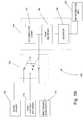
- Fig. 1Ashows a block diagram of a construction of a system 100, which is not according to the invention, for powering a refrigeration unit 105 using power from a belt driven alternator 110, from high-voltage batteries 115 of a hybrid vehicle, and from shore power 120.
- a switch 125selects which of the three power sources 110, 115, and 120 is used.
- the switch 125is a manual switch, where a user selects which power source 110, 115, and 120 to use.
- the switch 125is automatic, where a controller senses which power source(s) are providing sufficient power to operate the refrigeration unit 105 and selects the most appropriate power source to use.
- shore power 120is used whenever it is available, followed by power from the high-voltage batteries 115, and finally by power from the belt driven alternator 110.
- the controllermay control operation of an internal combustion engine used to drive the alternator, turning on the engine when there is insufficient power available from the shore power 120 or the high-voltage batteries 115, and turning off the engine when there is sufficient power available from either the shore power 120 or the high-voltage batteries 115, thus saving energy (i.e., fuel).
- the power available from the belt driven alternator 110is about 150 to 600 volts AC (VAC)
- the power available from the high-voltage batteries 115is about 263 to 408 volts DC (VDC)
- the power available from shore power 120is about 150 to 600 VAC.
- AC poweris assumed to be three-phase, however the invention contemplates the use of single-phase AC power as well.
- the power from one of the power sources 110, 115, and 120is applied a power converter 130 including an accumulation choke 135, a pulse-width-modulated (PWM) rectifier 140, and a frequency inverter 145.
- the accumulation choke 135is coupled to the PWM rectifier 140.
- the accumulation choke 135operates with the PWM rectifier 140 to convert/modify the power received from the belt driven alternator 110, the high-voltage batteries 115, or the share power 120 to a DC voltage having a maximum amplitude of about 750 VDC.
- the DC voltageis provided to the frequency inverter 145 which converts the DC voltage to a variable voltage of 0 to 525 VAC having a frequency of about 0 to 100 Hz, which is provided to the refrigeration unit 105.
- the DC power from the PWM rectifier 140is also used to supply a DC chopper for an electric heater.
- the DC chopperprovides DC power having a variable voltage of about 0 to 750 V DC.
- Fig. 1Bshows a block diagram of a construction according to the invention of a system 100' for powering a refrigeration unit 105 using power from a belt driven alternator 110, from high-voltage batteries 115 of a hybrid vehicle, and from shore power 120.
- a switch 125'selects which of the three power sources 110, 115, and 120 is used.
- the switch 125'has multiple throws such that when power from the belt driven alternator 110 is selected, the alternator 110 is connected directly to the PWM rectifier 140, bypassing the accumulation choke 135.
- the operation of the system 100'is the same as the operation of system 100 described above.
- the construction shown in Fig. 1Bcan be used when the inductance of the belt driven alternator 110 is great enough that the accumulation choke 135 is not necessary.
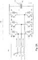
- Fig. 2Ashows a schematic diagram of a construction of the accumulation choke 135 and a full-controlled PWM rectifier 140'.
- the accumulation choke 135includes a plurality of inductors 150.
- the full-controlled PWM rectifier 140'includes six insulated gate bipolar transistors (IGBT) 155-160, each IGBT 155-160 having a diode 165-170 connected across its collector and emitter, and a capacitor 175.
- IGBTinsulated gate bipolar transistors
- Fig. 2Bshows a schematic diagram of a construction of the accumulation choke 135 and a half-controlled PWM rectifier 140".
- the accumulation choke 135includes a plurality of inductors 150.
- the half-controlled PWM rectifier 140"includes three insulated gate bipolar transistors (IGBT) 158-160, each IGBT 158-160 having a diode 168-170 connected across its collector and emitter, three diodes 155-157 connected in an upper branch of the half-controller PWM rectifier 140", and a capacitor 175.
- IGBTinsulated gate bipolar transistors
- Fig. 3Ashows a schematic representation of the accumulation choke 135 and a full-controlled PWM rectifier 140' for use with DC input power from the high-voltage batteries 115.
- the accumulation choke 135 and the full-controlled PWM rectifier 140'include all the same components as described above with respect to Fig. 2A ; however, the DC input voltage is applied to each inductor 150 and the upper IGBTs 155-157 are not used (i.e., they remain open).
- Fig. 3Bshows a schematic diagram of a construction of the accumulation choke 135 and a half-controlled PWM rectifier 140" for use with DC input power from the high-voltage batteries 115.
- the accumulation choke 135includes a plurality of inductors 150.
- the half-controlled PWM rectifier 140"includes three insulated gate bipolar transistors (IGBT) 158-160, each IGBT 158-160 having a diode 168-170 connected across its collector and emitter, three diodes 155-157 connected in an upper branch of the half-controller PWM rectifier 140", and a capacitor 175.
- IGBTinsulated gate bipolar transistors
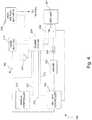
- Fig. 4shows a block diagram of a construction of a hybrid vehicle system 200 including a refrigeration unit 205.
- the system 200includes, among other things, a 12 VDC battery 210, a set of high-voltage batteries 215, a vehicle controller 220, a refrigeration unit controller 225, a refrigeration power system 230 including a connection to shore power 240, a refrigeration unit power switch 245, and a generator set including an internal combustion engine 250 driving an alternator 255.
- an internal combustion engine 250drives a compressor and fans of the refrigeration unit 205 directly by one or more belts.
- an electric motoris powered by the shore power 240 and drives a compressor and fans of the refrigeration unit 205 directly by one or more belts.
- a master switch 260enables the entire system 200.
- the power system 230receives power from the shore power connection 240 and the high-voltage batteries 215, and provides power, if available, from either the shore power connection 240 or the high-voltage batteries 215 to the refrigeration unit power switch 245.
- the vehicle controller 220provides an indication to the power system 230, via line 265, that power is available from the high-voltage batteries 215.
- the power system 230provides to the refrigeration unit controller 225, via line 270, an indication that power is available from either the shore power connection 240 or the high-voltage batteries 215, and is being provided to the refrigeration unit power switch 245.
- the refrigeration unit controller 225provides to the power unit 230, via line 275, an indication that the refrigeration unit 205 is on or off.
- the refrigeration unit controller 225controls the refrigeration unit power switch 245, switching between power provided by the power system 230 or, if power is not available from the power system 230, power provided by the belt driven alternator 255.
- the refrigeration unit controller 225turns on the internal combustion engine 250 which drives, via a belt, the alternator 255.
- the alternator 255then provides power to the refrigeration unit power switch 245, which is set, by the refrigeration unit controller 225, to provide the power from the alternator 255 to the refrigeration unit 205.
- there may be no alternator present in the system 200instead the internal combustion engine 250 drives a compressor and fans of the refrigeration unit 205 directly.
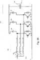
- Fig. 5shows a construction of a portion of the power system 230.
- the system 230includes an AC power connector 300 and a DC power connector 305.
- the AC connector 300includes three connections L1, L2, and L3 for connecting three-phase shore power (if available) to the system 230.
- the DC connector 305includes a positive 310 and a negative 315 connection for connecting to the high-voltage batteries 115.
- Each input line L1, L2, L3, 310, and 315is connected to the rest of the system 230 through a fuse FSUP1-FSUP5 sized appropriately for the voltage and current received on its respective input line L1, L2, L3, 310, and 315.
- Each input line L1, L2, L3, 310, and 315is also connected to the power converter 130 through a normally-open relay 320-326.
- the normally-open relays 320-322are closed to provide the AC shore power to the power converter 130, and when shore power is not available and DC power from the high-voltage batteries 115 is available, the normally-open relays 323-326 are closed to provide the DC power to the power converter 130.
- the AC normally-open relays 320-322are closed, the DC normally-open relays 323-326 are open, and when the DC normally-open relays 323-326 are closed, the AC normally-open relays 320-322 are open.
- an interlock modulemonitors relays 320-322 and 323-326 to ensure that only one of the relay groups 320-322 or 323-326 is closed at any time.
- the system 230also includes AC pre-charging circuits having normally-open relays 330 and 331 and resistors 332 and 333, and a DC pre-charging circuit including a normally-open relay 334 and resistor 335.
- the pre-charging circuitsare used when power is initially applied to the power system 230, and during a transition from AC power to DC power or from DC power to AC power. During a transition, the pre-charging circuits maintain power to the power converter 130, and allow the AC or DC power to be completely removed before the DC or AC power, being transitioned to, is connected.
- AC or DC poweris provided to the accumulation choke 135 and the PWM rectifier 140 of the power converter 130.
- the accumulation choke 135 and the PWM rectifier 140convert the AC or DC power to DC power having a maximum voltage of about 750 volts.
- the DC poweris the provided to the inverter 145 which converts the DC power to three-phase AC power having a variable voltage of 0 to 525 volts and frequency of about 0 to 100 Hz. In the construction shown in Fig. 4 , this AC power is then provided to the refrigeration unit 205 via the refrigeration unit power switch 245.
- the DC power from the PWM rectifier 140is also used to supply a DC chopper for an electric heater.
- the DC chopperprovides DC power having a variable voltage of about 0 to 750 V DC.
- Fig. 6shows a circuit 350 for controlling the application of AC or DC power to the power converter 130 for the system 230 shown in Fig. 5 .
- the circuit 350includes an AC delay 355 having a normally-closed switch 360 and a normally-open switch 365, a DC delay 370 having a normally-closed switch 375 and a normally-open switch 380, and a plurality of coils 390-396 for closing corresponding normally-open relays 320-326 shown in Fig. 5 .
- a switch 400selects either AC or DC power. In the construction shown, the switch 400 is a manual switch requiring an operator to select the AC or DC power.
- the switch 400is an automatic switch where AC power is automatically chosen if available, and if AC power is not available but DC power is available, DC power is automatically chosen. In examples which are not part of the invention, DC power is automatically chosen if available and AC power is chosen if available when DC power is not available. In some embodiments, if the switch 400 is off, and neither AC nor DC power is available, an internal combustion engine drives the refrigeration unit directly when the refrigeration unit is on.
- the switch 400When the switch 400 is put into the AC position, power is provided to the AC delay 355 and to the AC pre-charge coil 395.
- the power provided to the AC pre-charge coil 395closes the AC pre-charge normally-open relays 330-331 ( Fig. 5 ) applying AC power through resistors 332 and 333 to the power converter 130.
- the AC delay 355opens the AC normally-closed switch 360 and closes the AC normally-open switch 365.
- the AC normally-closed switch 360opens, power is removed from the AC pre-charge coil 395 and the AC pre-charge normally-open relays 330-331 open.
- the AC normally-open switch 365closes, power is applied to the AC coil 396 and the AC normally-open relays 320-322 close providing three-phase AC power to the power converter 130.
- the switch 400When the switch 400 is put into the DC position, power is provided to the DC delay 370 and to the DC pre-charge coil 391, and to DC negative coil 390.
- the power provided to the DC pre-charge coil 391closes the DC pre-charge normally-open relay 334 ( Fig. 5 ) applying DC power through resistor 335 to the power converter 130.
- the power provided to the DC negative coil 390closes the normally-open relay 326 connecting the negative connection 315 from the high-voltage batteries 215 to the power converter 130.
- a delay periode.g., five seconds
- the DC delay 370opens the DC normally-closed switch 375 and closes the DC normally-open switch 380.
- Fig. 7shows an alternative construction of a power converter 405 where multiple power converters 410-425 are employed for powering various devices such as a compressor motor 430, an electric heater 435, an evaporator fan 440, and a condenser fan 445.
- Figs. 8A and 8Bshow a schematic diagram of a construction of the power system 230 ( Fig. 4 ).
- system poweris turned on (switch 260 in Fig. 4 is closed)
- normally-open relay K7closes.
- shore poweris available, i.e., three-phase AC power is provided to L1, L2, L3, and a phase select module 450 receives power from normally-open relay K7 and the AC power lines L1, L2, L3.
- the phase select module 450then provides power to line 8EA.
- the power on line 8EAinitiates a five second delay timer 455 and simultaneously powers coil P.
- the power to coil Pcloses normally-open relays P1 and P2, and opens normally-closed relay P2.
- the five second delay timer 455provides power to output MPT which is provided to the refrigeration unit controller 225 to indicate that power is available from the power system 230 ( Fig. 4 ). If the refrigeration unit controller 225 indicates that the refrigeration unit 205 is on, normally-open relay K13 is closed providing power to coil MCA. The power to coil MCA causes normally-open relays MCA to close, supplying the AC shore power to the power converter 130, which in turn supplies power to a condenser motor 460 (providing normally-open relays K14 are closed).
- normally-closed relay P2is closed. If AC shore power is not available, normally-closed relay P2 is closed. If the vehicle controller 220 ( Fig. 4 ) indicates that vehicle power is available, the vehicle controller 220 provides power to a five second delay timer 465. After a five second delay, the timer 465 allows power to be applied to a coil T closing normally-open relay T1 and providing power to output MPT, which is provided to the refrigeration unit controller 225 to indicate that power is available from the power system 230 ( Fig. 4 ). If the refrigeration unit controller 225 indicates that the refrigeration unit 205 is on, normally-open relay K13 is closed, providing power to coil MCB.
- the power to coil MCBcauses normally-open relays MCB to close, supplying the DC power from the high-voltage batteries 215 to the power converter 130, which in turn supplies power to the condenser motor 460 (providing normally-open relays K14 are closed).
- the output MPT to the refrigeration unit controller 225is low and the refrigeration unit controller 225 starts the engine 250 which drives the refrigeration unit 205 directly.
- Figs. 9A , 9B , 9C , and 9Dshow a schematic diagram of an alternative construction of a power system 500.
- Fig. 10shows an alternate construction of a power system 505.
- the system 505includes a first AC power connector 510, a second AC power connector 515, and a DC power connector 520.
- the first AC connector 510includes three connections L1, L2, and L3 for connecting three-phase power from the belt driven alternator 255 to the system 505.
- the second AC connector 515includes three connections L1', L2', and L3' for connecting three-phase shore power (if available) to the system 505.
- the DC connector 520includes a positive connection 525 and a negative 530 connection for connecting to the high-voltage batteries 215 to the system 505.
- Each input line L1, L2, L3, L1', L2', L3', 525, and 530is connected to the rest of the system 505 through a fuse FSUP1-FSUP8 sized appropriately for the voltage and current received on its respective input line L1, L2, L3, L1', L2', L3', 525, and 530.
- Each input line L1, L2, L3, L1', L2', L3', 525, and 530is also connected to the power converter 130 through a normally-open relay 535-544.
- the normally-open relays 538-540are closed to provide the AC shore power to the power converter 130
- the normally-open relays 541-544are closed to provide the DC power to the power converter 130.
- the normally-open relays 535-537are closed to provide AC power from the alternator 255 to the power converter 130. Only one set of normally-open relays 535-537, 538-540, or 541-544 are closed at any time.
- the system 505also includes first AC pre-charging circuits having normally-open relays 550 and 551 and resistors 552 and 553, second AC pre-charging circuits having normally-open relays 555 and 556 and resistors 557 and 558, and a DC pre-charging circuit having a normally-open relay 560 and a resistor 561.
- the pre-charging circuitsare used when power is initially applied to the power system 505, and during a transition between one input power to another to maintain power to the power converter 130 during the transition, and allowing the power being transitioned from to be completely removed before the power being transitioned to is connected.
- AC or DC poweris provided to the accumulation choke 135 and the PWM rectifier 140 of the power converter 130 convert the AC or DC power to DC power having a maximum voltage of about 750 volts.
- the DC poweris then provided to the inverter 145, which converts the DC power to three-phase AC power having a voltage of 0 to 525 volts.
- this AC poweris then provided to the refrigeration unit 205 via the refrigeration unit power switch 245.
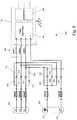
- Fig. 11shows a circuit 600 for controlling the application of the first AC power, the second AC power, or the DC power to the power converter 130 for the system 505 shown in Fig. 10 .
- the circuit 600includes a first AC delay 605 having a normally-closed switch 610 and a normally-open switch 615, a second AC delay 620 having a normally-closed switch 625 and a normally-open switch 630, a DC delay 635 having a normally-closed switch 640 and a normally-open switch 645, and a plurality of coils 650-658 for closing corresponding normally-open relays 534-544, 550-551, 555, 556, and 560 shown in Fig. 10 .
- a switch 660selects either the first AC power, the second AC power, or the DC power.
- the switch 660is a manual switch requiring an operator to select the power.
- the switch 660is an automatic switch where the second AC power (shore power) is automatically chosen if available, and if the first AC power is not available but DC power is available, the DC power is automatically chosen. If neither the second AC power nor the DC power is available, the switch automatically chooses the first AC power.
- the circuit 600operates similar to the operation of circuit 350 of Fig. 6 with the addition of a second AC power.
- a liquid cooling system of the hybrid vehicleis used to cool one or more components of the power system 230 (e.g., the power converter 130) and/or one or more components of the alternator 255 (e.g., the belt driven alternator 110).
- a liquid cooling system of the refrigeration unit 205is used to cool one or more components of the power system 230 and/or one or more components of the alternator 255.
- shore poweris provided to a charging circuit, in addition to the power system 230, for charging the high-voltage batteries 215.
- the refrigeration unit 205is operated exclusively using either DC power from the high-voltage batteries 215 or AC shore power 240.
- Fig. 12shows a schematic diagram of an alternative construction of a full-controlled PWM rectifier 700 incorporating a pre-charging circuit 705.
- the full-controlled PWM rectifier 700includes six insulated gate bipolar transistors (IGBT) 155-160, each IGBT 155-160 having a diode 165-170 connected across its collector and emitter, and operates the same as system 100 described above.
- the pre-charging circuit 705includes a capacitor 715, a resistor 720, a diode 725, and an IGBT 730.
- the pre-charging circuit 705operates to buffer a current surge encountered when switching from one power source to a second power source, and eliminates the need for the pre-charging and delay circuits described for the controllers above.
- the pre-charging circuit 705operates by opening the IGBT 730 prior to transitioning the power source. Applying the second power source and removing the first power source while the IGBT 730 is open. The IGBT 730 is held open until the capacitor 715 is fully charged forcing current to travel through the resistor 720. Once the capacitor 715 is fully charged, the IGBT 730 is closed.
- Systems according to the inventionare capable of being used in non-hybrid vehicles, receiving AC power from an alternator of the vehicle during operation of the vehicle and having a shore power connection for use when the vehicle is not operating.
- the inventionprovides a system and method for powering a refrigeration unit of a hybrid vehicle.
Landscapes
- Engineering & Computer Science (AREA)
- Power Engineering (AREA)
- Physics & Mathematics (AREA)
- Mechanical Engineering (AREA)
- Thermal Sciences (AREA)
- General Engineering & Computer Science (AREA)
- Chemical & Material Sciences (AREA)
- Combustion & Propulsion (AREA)
- Life Sciences & Earth Sciences (AREA)
- Sustainable Development (AREA)
- Sustainable Energy (AREA)
- Electric Propulsion And Braking For Vehicles (AREA)
Description
- Refrigeration units, e.g., for refrigerated trucks or rail cars, typically include an internal combustion engine which drives a compressor of the refrigeration unit via a belt. Some refrigeration units also include means for plugging the unit into electrical mains (shore power) for powering the unit when the unit is not in transit. The shore power powers an electric motor which drives the compressor via a belt.
EP1504227A1 discloses an air conditioning system for use in an over-the-road or off road vehicle that allows operation during both engine on and engine off conditions.- The invention is defined in the attached independent claims to which reference should now be made. Further, optional features may be found in the sub-claims appended thereto.
- According to
claim 1, the invention provides a power system for powering a refrigeration unit of a hybrid vehicle. The power system includes a first connection, a second connection, a third connection, and a power converter. The first connection is configured to receive power from a first power source. Where the first power source is a first high-voltage alternating current (AC) power source between 150 and 600 VAC. The second connection is configured to receive power from a second power source. Where the second power source is a high-voltage direct current (DC) power source between 263 to 408 VDC volts. The third connection is configured to receive power from a third power source. Where the third power source is a second high-voltage AC power source between 150 and 600 VAC. The power converter is configured to supply power to the refrigeration unit. The power system couples the first power source to the power converter when power is received at the first connection, couples the second power source to the power converter when power is received at the second connection but not the first connection, and couples the third power source to the power converter when power is not available from both the first and second connections. A switch is configured to allow only one of the first power source, the second power source, and the third power source to be coupled to the power converter at any one time. The power converter includes an accumulation choke that includes a plurality of inductors, a PWM rectifier configured to convert the received power to a second DC power, and a frequency inverter that are connected in series. The switch connects one of the first power source and the second power source to the accumulator choke and connects the third power source to the PWM rectifier. - In another embodiment, the invention provides a method of powering a refrigeration unit according to
claim 10. - Other aspects of the invention will become apparent by consideration of the detailed description and accompanying drawings.
Fig. 1A is a block diagram of a construction of a power system for a hybrid vehicle with a refrigeration unit that does not embody the invention.Fig. 1B is a block diagram of an alternative construction of a power system for a hybrid vehicle with a refrigeration unit.Fig. 2A is a schematic diagram of a construction of an accumulation choke and a full-control PWM rectifier for use with three-phase AC power.Fig. 2B is a schematic diagram of a construction of an accumulation choke and a half-control PWM rectifier for use with three-phase AC power.Fig. 3A is a schematic diagram of a construction of an accumulation choke and a full-control PWM rectifier for use with DC power.Fig. 3B is a schematic diagram of a construction of an accumulation choke and a half-control PWM rectifier for use with DC power.Fig. 4 is a block diagram of a construction of a system for powering a refrigeration unit of a hybrid vehicle.Fig. 5 is a schematic diagram of a construction of a circuit of a power system for using AC or DC power to generate three-phase AC power.Fig. 6 is a schematic diagram of a construction of a circuit for controlling the operation of the circuit ofFig. 5 .Fig. 7 is an alternative construction of a power system for powering multiple systems.Figs. 8A and8B are a schematic diagram of another construction of a power system.Figs. 9A ,9B ,9C , and9D are a schematic diagram of another construction of a power system.Fig. 10 is a block diagram of another construction of a system for powering a refrigeration unit of a hybrid vehicle.Fig. 11 is a schematic diagram of another construction of a circuit of a power system for using AC or DC power to generate three-phase AC power.Fig. 12 is a schematic diagram of a construction of a full-control PWM rectifier, incorporating a pre-charge circuit, for use with three-phase AC power.- Before any embodiments of the invention are explained in detail, it is to be understood that the invention is not limited in its application to the details of construction and the arrangement of components set forth in the following description or illustrated in the following drawings. The invention is capable of other embodiments and of being practiced or of being carried out in various ways. Also, it is to be understood that the phraseology and terminology used herein is for the purpose of description and should not be regarded as limiting. The use of "including," "comprising," or "having" and variations thereof herein is meant to encompass the items listed thereafter and equivalents thereof as well as additional items. Unless specified or limited otherwise, the terms "mounted," "connected," "supported," and "coupled" and variations thereof encompass direct and indirect mountings, connections, supports, and couplings. Further, "connected" and "coupled" are not restricted to physical or mechanical connections or couplings.
Fig. 1A shows a block diagram of a construction of asystem 100, which is not according to the invention, for powering arefrigeration unit 105 using power from a belt drivenalternator 110, from high-voltage batteries 115 of a hybrid vehicle, and fromshore power 120. Aswitch 125 selects which of the threepower sources switch 125 is a manual switch, where a user selects whichpower source switch 125 is automatic, where a controller senses which power source(s) are providing sufficient power to operate therefrigeration unit 105 and selects the most appropriate power source to use. For example, in some embodiments,shore power 120 is used whenever it is available, followed by power from the high-voltage batteries 115, and finally by power from the belt drivenalternator 110. In addition, the controller may control operation of an internal combustion engine used to drive the alternator, turning on the engine when there is insufficient power available from theshore power 120 or the high-voltage batteries 115, and turning off the engine when there is sufficient power available from either theshore power 120 or the high-voltage batteries 115, thus saving energy (i.e., fuel).- According to the invention, the power available from the belt driven
alternator 110 is about 150 to 600 volts AC (VAC), the power available from the high-voltage batteries 115 is about 263 to 408 volts DC (VDC), and the power available fromshore power 120 is about 150 to 600 VAC. In the construction shown, AC power is assumed to be three-phase, however the invention contemplates the use of single-phase AC power as well. - Depending on the position of the
switch 125, set either manually or automatically, the power from one of thepower sources power converter 130 including anaccumulation choke 135, a pulse-width-modulated (PWM)rectifier 140, and afrequency inverter 145. Theaccumulation choke 135 is coupled to thePWM rectifier 140. Theaccumulation choke 135 operates with thePWM rectifier 140 to convert/modify the power received from the belt drivenalternator 110, the high-voltage batteries 115, or theshare power 120 to a DC voltage having a maximum amplitude of about 750 VDC. The DC voltage is provided to thefrequency inverter 145 which converts the DC voltage to a variable voltage of 0 to 525 VAC having a frequency of about 0 to 100 Hz, which is provided to therefrigeration unit 105. In some constructions, the DC power from thePWM rectifier 140 is also used to supply a DC chopper for an electric heater. The DC chopper provides DC power having a variable voltage of about 0 to 750 V DC. Fig. 1B shows a block diagram of a construction according to the invention of a system 100' for powering arefrigeration unit 105 using power from a belt drivenalternator 110, from high-voltage batteries 115 of a hybrid vehicle, and fromshore power 120. Again a switch 125' selects which of the threepower sources alternator 110 is selected, thealternator 110 is connected directly to thePWM rectifier 140, bypassing theaccumulation choke 135. Except for thealternator 110 being connected directly to thePWM rectifier 140, the operation of the system 100' is the same as the operation ofsystem 100 described above. The construction shown inFig. 1B can be used when the inductance of the belt drivenalternator 110 is great enough that theaccumulation choke 135 is not necessary.Fig. 2A shows a schematic diagram of a construction of theaccumulation choke 135 and a full-controlled PWM rectifier 140'. Theaccumulation choke 135 includes a plurality ofinductors 150. The full-controlled PWM rectifier 140' includes six insulated gate bipolar transistors (IGBT) 155-160, each IGBT 155-160 having a diode 165-170 connected across its collector and emitter, and acapacitor 175.Fig. 2B shows a schematic diagram of a construction of theaccumulation choke 135 and a half-controlledPWM rectifier 140". Theaccumulation choke 135 includes a plurality ofinductors 150. The half-controlledPWM rectifier 140" includes three insulated gate bipolar transistors (IGBT) 158-160, each IGBT 158-160 having a diode 168-170 connected across its collector and emitter, three diodes 155-157 connected in an upper branch of the half-controller PWM rectifier 140", and acapacitor 175.Fig. 3A shows a schematic representation of theaccumulation choke 135 and a full-controlled PWM rectifier 140' for use with DC input power from the high-voltage batteries 115. Theaccumulation choke 135 and the full-controlled PWM rectifier 140' include all the same components as described above with respect toFig. 2A ; however, the DC input voltage is applied to eachinductor 150 and the upper IGBTs 155-157 are not used (i.e., they remain open).Fig. 3B shows a schematic diagram of a construction of theaccumulation choke 135 and a half-controlledPWM rectifier 140" for use with DC input power from the high-voltage batteries 115. Theaccumulation choke 135 includes a plurality ofinductors 150. The half-controlledPWM rectifier 140" includes three insulated gate bipolar transistors (IGBT) 158-160, each IGBT 158-160 having a diode 168-170 connected across its collector and emitter, three diodes 155-157 connected in an upper branch of the half-controller PWM rectifier 140", and acapacitor 175.Fig. 4 shows a block diagram of a construction of ahybrid vehicle system 200 including arefrigeration unit 205. Thesystem 200 includes, among other things, a 12VDC battery 210, a set of high-voltage batteries 215, avehicle controller 220, arefrigeration unit controller 225, arefrigeration power system 230 including a connection to shorepower 240, a refrigerationunit power switch 245, and a generator set including aninternal combustion engine 250 driving analternator 255. In some constructions, aninternal combustion engine 250 drives a compressor and fans of therefrigeration unit 205 directly by one or more belts. In some constructions, an electric motor is powered by theshore power 240 and drives a compressor and fans of therefrigeration unit 205 directly by one or more belts.- A
master switch 260 enables theentire system 200. Thepower system 230 receives power from theshore power connection 240 and the high-voltage batteries 215, and provides power, if available, from either theshore power connection 240 or the high-voltage batteries 215 to the refrigerationunit power switch 245. - The
vehicle controller 220 provides an indication to thepower system 230, vialine 265, that power is available from the high-voltage batteries 215. Thepower system 230 provides to therefrigeration unit controller 225, vialine 270, an indication that power is available from either theshore power connection 240 or the high-voltage batteries 215, and is being provided to the refrigerationunit power switch 245. Therefrigeration unit controller 225 provides to thepower unit 230, vialine 275, an indication that therefrigeration unit 205 is on or off. Therefrigeration unit controller 225 controls the refrigerationunit power switch 245, switching between power provided by thepower system 230 or, if power is not available from thepower system 230, power provided by the belt drivenalternator 255. If therefrigeration unit 205 is on, power is provided to therefrigeration unit 205 by thepower system 230 if power is available from either theshore power connection 240 or the high-voltage batteries 215. If power is not available from thepower system 230 and therefrigeration unit 205 is on, therefrigeration unit controller 225 turns on theinternal combustion engine 250 which drives, via a belt, thealternator 255. Thealternator 255 then provides power to the refrigerationunit power switch 245, which is set, by therefrigeration unit controller 225, to provide the power from thealternator 255 to therefrigeration unit 205. In alternative constructions, there may be no alternator present in thesystem 200, instead theinternal combustion engine 250 drives a compressor and fans of therefrigeration unit 205 directly. Fig. 5 shows a construction of a portion of thepower system 230. Thesystem 230 includes anAC power connector 300 and aDC power connector 305. TheAC connector 300 includes three connections L1, L2, and L3 for connecting three-phase shore power (if available) to thesystem 230. TheDC connector 305 includes a positive 310 and a negative 315 connection for connecting to the high-voltage batteries 115. Each input line L1, L2, L3, 310, and 315 is connected to the rest of thesystem 230 through a fuse FSUP1-FSUP5 sized appropriately for the voltage and current received on its respective input line L1, L2, L3, 310, and 315. Each input line L1, L2, L3, 310, and 315 is also connected to thepower converter 130 through a normally-open relay 320-326. As discussed below, when shore power is available, the.normally-open relays 320-322 are closed to provide the AC shore power to thepower converter 130, and when shore power is not available and DC power from the high-voltage batteries 115 is available, the normally-open relays 323-326 are closed to provide the DC power to thepower converter 130. When the AC normally-open relays 320-322 are closed, the DC normally-open relays 323-326 are open, and when the DC normally-open relays 323-326 are closed, the AC normally-open relays 320-322 are open. In some constructions, an interlock module monitors relays 320-322 and 323-326 to ensure that only one of the relay groups 320-322 or 323-326 is closed at any time.- The
system 230 also includes AC pre-charging circuits having normally-open relays resistors open relay 334 andresistor 335. The pre-charging circuits are used when power is initially applied to thepower system 230, and during a transition from AC power to DC power or from DC power to AC power. During a transition, the pre-charging circuits maintain power to thepower converter 130, and allow the AC or DC power to be completely removed before the DC or AC power, being transitioned to, is connected. - As discussed above with respect to
Figs. 1-3 , if available, AC or DC power is provided to theaccumulation choke 135 and thePWM rectifier 140 of thepower converter 130. Theaccumulation choke 135 and thePWM rectifier 140 convert the AC or DC power to DC power having a maximum voltage of about 750 volts. The DC power is the provided to theinverter 145 which converts the DC power to three-phase AC power having a variable voltage of 0 to 525 volts and frequency of about 0 to 100 Hz. In the construction shown inFig. 4 , this AC power is then provided to therefrigeration unit 205 via the refrigerationunit power switch 245. In some constructions, the DC power from thePWM rectifier 140 is also used to supply a DC chopper for an electric heater. The DC chopper provides DC power having a variable voltage of about0 to 750 V DC. Fig. 6 shows acircuit 350 for controlling the application of AC or DC power to thepower converter 130 for thesystem 230 shown inFig. 5 . Thecircuit 350 includes anAC delay 355 having a normally-closedswitch 360 and a normally-open switch 365, aDC delay 370 having a normally-closedswitch 375 and a normally-open switch 380, and a plurality of coils 390-396 for closing corresponding normally-open relays 320-326 shown inFig. 5 . Aswitch 400 selects either AC or DC power. In the construction shown, theswitch 400 is a manual switch requiring an operator to select the AC or DC power. In some embodiments, theswitch 400 is an automatic switch where AC power is automatically chosen if available, and if AC power is not available but DC power is available, DC power is automatically chosen. In examples which are not part of the invention, DC power is automatically chosen if available and AC power is chosen if available when DC power is not available. In some embodiments, if theswitch 400 is off, and neither AC nor DC power is available, an internal combustion engine drives the refrigeration unit directly when the refrigeration unit is on.- When the
switch 400 is put into the AC position, power is provided to theAC delay 355 and to the ACpre-charge coil 395. The power provided to the ACpre-charge coil 395 closes the AC pre-charge normally-open relays 330-331 (Fig. 5 ) applying AC power throughresistors power converter 130. After a delay period (e.g., five seconds), theAC delay 355 opens the AC normally-closedswitch 360 and closes the AC normally-open switch 365. When the AC normally-closedswitch 360 opens, power is removed from the ACpre-charge coil 395 and the AC pre-charge normally-open relays 330-331 open. When the AC normally-open switch 365 closes, power is applied to theAC coil 396 and the AC normally-open relays 320-322 close providing three-phase AC power to thepower converter 130. - When the
switch 400 is put into the DC position, power is provided to theDC delay 370 and to the DCpre-charge coil 391, and to DCnegative coil 390. The power provided to the DCpre-charge coil 391 closes the DC pre-charge normally-open relay 334 (Fig. 5 ) applying DC power throughresistor 335 to thepower converter 130. The power provided to the DCnegative coil 390 closes the normally-open relay 326 connecting thenegative connection 315 from the high-voltage batteries 215 to thepower converter 130. After a delay period (e.g., five seconds), theDC delay 370 opens the DC normally-closedswitch 375 and closes the DC normally-open switch 380. When the DC normally-closedswitch 375 opens, power is removed from the DCpre-charge coil 391 and the DC pre-charge normally-open relay 324 opens. When the DC normally-open switch 380 closes, power is applied to the DC coils 392-394 and the DC normally-open relays 323-325 close providing DC power to thepower converter 130. Fig. 7 shows an alternative construction of apower converter 405 where multiple power converters 410-425 are employed for powering various devices such as acompressor motor 430, anelectric heater 435, anevaporator fan 440, and acondenser fan 445.Figs. 8A and8B show a schematic diagram of a construction of the power system 230 (Fig. 4 ). When system power is turned on (switch 260 inFig. 4 is closed), normally-open relay K7 closes. If shore power is available, i.e., three-phase AC power is provided to L1, L2, L3, and a phaseselect module 450 receives power from normally-open relay K7 and the AC power lines L1, L2, L3. The phaseselect module 450 then provides power to line 8EA. The power on line 8EA initiates a fivesecond delay timer 455 and simultaneously powers coil P. The power to coil P closes normally-open relays P1 and P2, and opens normally-closed relay P2. After five seconds, the fivesecond delay timer 455 provides power to output MPT which is provided to therefrigeration unit controller 225 to indicate that power is available from the power system 230 (Fig. 4 ). If therefrigeration unit controller 225 indicates that therefrigeration unit 205 is on, normally-open relay K13 is closed providing power to coil MCA. The power to coil MCA causes normally-open relays MCA to close, supplying the AC shore power to thepower converter 130, which in turn supplies power to a condenser motor 460 (providing normally-open relays K14 are closed).- If AC shore power is not available, normally-closed relay P2 is closed. If the vehicle controller 220 (
Fig. 4 ) indicates that vehicle power is available, thevehicle controller 220 provides power to a fivesecond delay timer 465. After a five second delay, thetimer 465 allows power to be applied to a coil T closing normally-open relay T1 and providing power to output MPT, which is provided to therefrigeration unit controller 225 to indicate that power is available from the power system 230 (Fig. 4 ). If therefrigeration unit controller 225 indicates that therefrigeration unit 205 is on, normally-open relay K13 is closed, providing power to coil MCB. The power to coil MCB causes normally-open relays MCB to close, supplying the DC power from the high-voltage batteries 215 to thepower converter 130, which in turn supplies power to the condenser motor 460 (providing normally-open relays K14 are closed). - If neither AC shore power nor DC power from the high-
voltage batteries 215 is available, the output MPT to therefrigeration unit controller 225 is low and therefrigeration unit controller 225 starts theengine 250 which drives therefrigeration unit 205 directly. Figs. 9A ,9B ,9C , and9D show a schematic diagram of an alternative construction of apower system 500.Fig. 10 shows an alternate construction of apower system 505. Thesystem 505 includes a firstAC power connector 510, a secondAC power connector 515, and aDC power connector 520. Thefirst AC connector 510 includes three connections L1, L2, and L3 for connecting three-phase power from the belt drivenalternator 255 to thesystem 505. Thesecond AC connector 515 includes three connections L1', L2', and L3' for connecting three-phase shore power (if available) to thesystem 505. TheDC connector 520 includes apositive connection 525 and a negative 530 connection for connecting to the high-voltage batteries 215 to thesystem 505. Each input line L1, L2, L3, L1', L2', L3', 525, and 530 is connected to the rest of thesystem 505 through a fuse FSUP1-FSUP8 sized appropriately for the voltage and current received on its respective input line L1, L2, L3, L1', L2', L3', 525, and 530. Each input line L1, L2, L3, L1', L2', L3', 525, and 530 is also connected to thepower converter 130 through a normally-open relay 535-544. As discussed below, when shore power is available, the normally-open relays 538-540 are closed to provide the AC shore power to thepower converter 130, and when shore power is not available and DC power from the high-voltage batteries 215 is available, the normally-open relays 541-544 are closed to provide the DC power to thepower converter 130. When neither shore power nor DC power is available, the normally-open relays 535-537 are closed to provide AC power from thealternator 255 to thepower converter 130. Only one set of normally-open relays 535-537, 538-540, or 541-544 are closed at any time.- The
system 505 also includes first AC pre-charging circuits having normally-open relays resistors 552 and 553, second AC pre-charging circuits having normally-open relays resistors 557 and 558, and a DC pre-charging circuit having a normally-open relay 560 and aresistor 561. The pre-charging circuits are used when power is initially applied to thepower system 505, and during a transition between one input power to another to maintain power to thepower converter 130 during the transition, and allowing the power being transitioned from to be completely removed before the power being transitioned to is connected. - As discussed above with respect to
Figs. 1-3 , if available, AC or DC power is provided to theaccumulation choke 135 and thePWM rectifier 140 of thepower converter 130 convert the AC or DC power to DC power having a maximum voltage of about 750 volts. The DC power is then provided to theinverter 145, which converts the DC power to three-phase AC power having a voltage of 0 to 525 volts. In the construction shown inFig. 4 , this AC power is then provided to therefrigeration unit 205 via the refrigerationunit power switch 245. Fig. 11 shows acircuit 600 for controlling the application of the first AC power, the second AC power, or the DC power to thepower converter 130 for thesystem 505 shown inFig. 10 . Thecircuit 600 includes afirst AC delay 605 having a normally-closedswitch 610 and a normally-open switch 615, asecond AC delay 620 having a normally-closedswitch 625 and a normally-open switch 630, aDC delay 635 having a normally-closedswitch 640 and a normally-open switch 645, and a plurality of coils 650-658 for closing corresponding normally-open relays 534-544, 550-551, 555, 556, and 560 shown inFig. 10 . Aswitch 660 selects either the first AC power, the second AC power, or the DC power. In the construction shown, theswitch 660 is a manual switch requiring an operator to select the power. In some constructions, theswitch 660 is an automatic switch where the second AC power (shore power) is automatically chosen if available, and if the first AC power is not available but DC power is available, the DC power is automatically chosen. If neither the second AC power nor the DC power is available, the switch automatically chooses the first AC power. Thecircuit 600 operates similar to the operation ofcircuit 350 ofFig. 6 with the addition of a second AC power.- In some constructions, a liquid cooling system of the hybrid vehicle is used to cool one or more components of the power system 230 (e.g., the power converter 130) and/or one or more components of the alternator 255 (e.g., the belt driven alternator 110). In other constructions, a liquid cooling system of the
refrigeration unit 205 is used to cool one or more components of thepower system 230 and/or one or more components of thealternator 255. - In some constructions, shore power is provided to a charging circuit, in addition to the
power system 230, for charging the high-voltage batteries 215. In some constructions, therefrigeration unit 205 is operated exclusively using either DC power from the high-voltage batteries 215 orAC shore power 240. Fig. 12 shows a schematic diagram of an alternative construction of a full-controlledPWM rectifier 700 incorporating apre-charging circuit 705. The full-controlledPWM rectifier 700 includes six insulated gate bipolar transistors (IGBT) 155-160, each IGBT 155-160 having a diode 165-170 connected across its collector and emitter, and operates the same assystem 100 described above. Thepre-charging circuit 705 includes acapacitor 715, aresistor 720, adiode 725, and anIGBT 730. Thepre-charging circuit 705 operates to buffer a current surge encountered when switching from one power source to a second power source, and eliminates the need for the pre-charging and delay circuits described for the controllers above. Thepre-charging circuit 705 operates by opening theIGBT 730 prior to transitioning the power source. Applying the second power source and removing the first power source while theIGBT 730 is open. TheIGBT 730 is held open until thecapacitor 715 is fully charged forcing current to travel through theresistor 720. Once thecapacitor 715 is fully charged, theIGBT 730 is closed.- Systems according to the invention are capable of being used in non-hybrid vehicles, receiving AC power from an alternator of the vehicle during operation of the vehicle and having a shore power connection for use when the vehicle is not operating.
- Thus, the invention provides a system and method for powering a refrigeration unit of a hybrid vehicle.
Claims (12)
- A power system (100) for powering a refrigeration unit (105) of a hybrid vehicle, the power system comprising:a first connection configured to receive power from a first power source (120), the first power source (120) being a first high-voltage alternating current (AC) power source between 150 and 600 VAC;a second connection configured to receive power from a second power source (115), the second power source (115) being a high-voltage direct current (DC) power source between 263 to 408 VDC;a third connection configured to receive power from a third power source (110), the third power source (110) being a second high-voltage AC power source between 150 and 600 VAC; anda power converter (130) configured to supply power to the refrigeration unit (105);wherein the power system (100) couples the first power source (120) to the power converter (130) when power is received at the first connection, couples the second power source (115) to the power converter (130) when power is received at the second connection but not the first connection, and couples the third power source (110) to the power converter (130) when power is not available from both the first and second connections;a switch (125) configured to allow only one of the first power source (120), the second power source (115), and the third power source (110) to be coupled to the power converter (130) at any one time,the power system (100) beingcharacterized in that the power converter (130) includes an accumulation choke (135) that includes a plurality of inductors (150), a PWM rectifier (140) configured to convert the received power to a second DC power, and a frequency inverter (145) that are connected in series,wherein the switch (125) connects one of the first power source (120) and the second power source (115) to the accumulator choke (135) and connects the third power source (110) to the PWM rectifier (140).
- The system of claim 1, wherein the second DC power is between about 0 and 750 volts.
- The system of claim 1, wherein the inverter is a frequency inverter (145) configured to receive the second DC power from the PWM rectifier (140) and convert the second DC power to a third AC voltage, the third AC voltage supplied to the refrigeration unit (105).
- The system of claim 3, wherein the third AC voltage has a voltage of between about 0 and 525 volts and a frequency between about 0 and 100 Hz.
- The system of claim 1, comprising the second power source being a plurality of high-voltage batteries (115) and the first power source being a shore power source (120).
- The system of claim 1, comprising the third power source (110) being an alternator (110) driven by an engine (250) and providing a high-voltage AC power to the refrigeration unit (105).
- The system of claim 1, comprising the first high-voltage AC power source which includes a shore power (120).
- The system of claim 1, wherein the high-voltage DC power source includes a plurality of high-voltage batteries (115) used to power a hybrid vehicle.
- The system of claim 1, comprising the second high-voltage AC power source which includes a belt-driven alternator (110).
- The system of claim 1, comprising the first high-voltage AC power source which includes a shore power (120), the high-voltage DC power source which includes a plurality of high-voltage batteries (115) used to power a hybrid vehicle, and the second high-voltage AC power source which includes a belt-driven alternator (110).
- A method of powering a refrigeration unit (105) of a hybrid vehicle, the method comprising:receiving at a first connection a high-voltage AC power between 150 and 600 VAC from an electric mains (120);receiving at a second connection a high-voltage DC power between 263 to 408 VDC from a plurality of batteries (115) of a hybrid vehicle;receiving at a third connection another high-voltage AC power between 150 and 600 VAC from a belt driven alternator (110);connecting one of the first connection, the second connection, and the third connection to a power converter (130) based on a position of a switch (125), the connecting act coupling one of the high-voltage DC power and the high-voltage AC power to the power converter (130) thereby resulting in a coupled power;disconnecting the coupled power from the power converter (130) when the position of the switch (125) has changed;allowing only one of the first connection, the second connection, and the third connection to be coupled to the power converter (130) at any one time;directing the high-voltage AC power from the first connection first through a plurality of inductors (150) of an accumulation choke (135) of the power converter (130), then through a PWM rectifier (140) and then through a frequency inverter (145) when the switch (125) connects the first connection to the power converter (130);directing the high-voltage DC power from the second connection first through the plurality of inductors (150) of the accumulation choke (135), then through the PWM rectifier (140) and then through the frequency inverter (145) when the switch (125) connects the second connection to the power converter (130);directing the other high-voltage AC power from the third connection first through the PWM rectifier (140) of the power converter (130) and then through the frequency inverter (145) when the switch (125) connects the third connection to the power converter (130);converting the high-voltage power into a second high-voltage AC power when the high-voltage DC power is coupled to the power converter (130), converting the high-voltage AC power into the second high-voltage AC power when the high-voltage AC power is coupled to the power converter (130), and converting the other high-voltage AC power into the second high-voltage AC power when the other high-voltage AC power is coupled to the power converter (130); andproviding the second high-voltage AC power to the refrigeration unit (105).
- The method of claim 11, wherein the disconnecting act further comprises transitioning from one of the high-voltage AC power and the high-voltage DC power to the other of the high-voltage AC power and the high-voltage DC power by coupling both the high-voltage AC power and the high-voltage DC power to power converter (130) for a period of time; or further comprising recharging the plurality of batteries (115) using the high-voltage AC power.
Priority Applications (1)
| Application Number | Priority Date | Filing Date | Title |
|---|---|---|---|
| EP20167375.3AEP3734189A1 (en) | 2009-03-10 | 2010-03-10 | Systems and methods of powering a refrigeration unit of a hybrid vehicle |
Applications Claiming Priority (2)
| Application Number | Priority Date | Filing Date | Title |
|---|---|---|---|
| US15896409P | 2009-03-10 | 2009-03-10 | |
| PCT/US2010/026840WO2010104960A1 (en) | 2009-03-10 | 2010-03-10 | Systems and methods of powering a refrigeration unit of a hybrid vehicle |
Related Child Applications (1)
| Application Number | Title | Priority Date | Filing Date |
|---|---|---|---|
| EP20167375.3ADivisionEP3734189A1 (en) | 2009-03-10 | 2010-03-10 | Systems and methods of powering a refrigeration unit of a hybrid vehicle |
Publications (3)
| Publication Number | Publication Date |
|---|---|
| EP2406560A1 EP2406560A1 (en) | 2012-01-18 |
| EP2406560A4 EP2406560A4 (en) | 2015-04-29 |
| EP2406560B1true EP2406560B1 (en) | 2020-04-29 |
Family
ID=42728750
Family Applications (2)
| Application Number | Title | Priority Date | Filing Date |
|---|---|---|---|
| EP10751362.4AActiveEP2406560B1 (en) | 2009-03-10 | 2010-03-10 | Systems and methods of powering a refrigeration unit of a hybrid vehicle |
| EP20167375.3APendingEP3734189A1 (en) | 2009-03-10 | 2010-03-10 | Systems and methods of powering a refrigeration unit of a hybrid vehicle |
Family Applications After (1)
| Application Number | Title | Priority Date | Filing Date |
|---|---|---|---|
| EP20167375.3APendingEP3734189A1 (en) | 2009-03-10 | 2010-03-10 | Systems and methods of powering a refrigeration unit of a hybrid vehicle |
Country Status (4)
| Country | Link |
|---|---|
| US (2) | US9689598B2 (en) |
| EP (2) | EP2406560B1 (en) |
| CN (1) | CN102422101B (en) |
| WO (1) | WO2010104960A1 (en) |
Families Citing this family (36)
| Publication number | Priority date | Publication date | Assignee | Title |
|---|---|---|---|---|
| DE102010003509A1 (en)* | 2010-03-31 | 2011-10-06 | Zf Friedrichshafen Ag | Power supply device and unit |
| US20120101673A1 (en)* | 2010-10-26 | 2012-04-26 | Jeffrey Andrew Caddick | Hybrid Vehicle Control System For Cold Plate Refrigeration And Method Of The Same |
| CN103502751B (en)* | 2011-04-04 | 2016-06-15 | 开利公司 | Transport refrigeration system and operational approach |
| JP5673474B2 (en)* | 2011-09-27 | 2015-02-18 | 三菱自動車工業株式会社 | Power switching device |
| US8605472B2 (en)* | 2011-10-12 | 2013-12-10 | Thermo King Corporation | Buck-boost rectifier, refrigeration system including a buck-boost rectifier, and method of providing power to a refrigeration unit via a buck-boost rectifier |
| US8953296B2 (en)* | 2011-11-14 | 2015-02-10 | Rockwell Automation Technologies, Inc. | AC pre-charge circuit |
| WO2014058610A1 (en)* | 2012-10-08 | 2014-04-17 | Thermo King Corporation | Systems and methods for powering a transport refrigeration system |
| CN103779887B (en) | 2012-10-22 | 2018-11-30 | 创科户外产品技术有限公司 | Double source battery charger |
| CN105073494B (en)* | 2012-12-31 | 2017-04-12 | 冷王公司 | Transport refrigeration unit battery charging system and method of operating same |
| FR3002797B1 (en)* | 2013-03-01 | 2015-04-03 | Arnauld Deloge | AIR CONDITIONING INSTALLATION |
| WO2015100397A1 (en) | 2013-12-26 | 2015-07-02 | Thermo King Corporation | Method and system for configuring a transport refrigeration unit battery charger for use in a transport refrigeration system |
| KR102220911B1 (en)* | 2014-01-06 | 2021-02-25 | 엘지전자 주식회사 | Refrigerator and home appliance |
| CN103944411A (en)* | 2014-04-10 | 2014-07-23 | 重庆瑜欣平瑞电子有限公司 | Generator frequency converter |
| CN104038121B (en)* | 2014-05-26 | 2016-08-17 | 株洲变流技术国家工程研究中心有限公司 | Magneto alternator commutation system |
| US10300831B2 (en) | 2016-06-01 | 2019-05-28 | Cummins Inc. | Hybrid reefer systems |
| US10300766B2 (en) | 2016-06-30 | 2019-05-28 | Emerson Climate Technologies, Inc. | System and method of controlling passage of refrigerant through eutectic plates and an evaporator of a refrigeration system for a container of a vehicle |
| US10532632B2 (en) | 2016-06-30 | 2020-01-14 | Emerson Climate Technologies, Inc. | Startup control systems and methods for high ambient conditions |
| US10414241B2 (en) | 2016-06-30 | 2019-09-17 | Emerson Climate Technologies, Inc. | Systems and methods for capacity modulation through eutectic plates |
| US10562377B2 (en) | 2016-06-30 | 2020-02-18 | Emerson Climate Technologies, Inc. | Battery life prediction and monitoring |
| US10828963B2 (en) | 2016-06-30 | 2020-11-10 | Emerson Climate Technologies, Inc. | System and method of mode-based compressor speed control for refrigerated vehicle compartment |
| US10328771B2 (en) | 2016-06-30 | 2019-06-25 | Emerson Climated Technologies, Inc. | System and method of controlling an oil return cycle for a refrigerated container of a vehicle |
| US10315495B2 (en) | 2016-06-30 | 2019-06-11 | Emerson Climate Technologies, Inc. | System and method of controlling compressor, evaporator fan, and condenser fan speeds during a battery mode of a refrigeration system for a container of a vehicle |
| US10569620B2 (en) | 2016-06-30 | 2020-02-25 | Emerson Climate Technologies, Inc. | Startup control systems and methods to reduce flooded startup conditions |
| IT201700058521A1 (en)* | 2017-05-30 | 2018-11-30 | Denso Thermal Systems Spa | Condensing unit of a refrigeration system for vehicles used for the transport of perishable goods. |
| EP3634792B1 (en) | 2017-06-07 | 2024-10-23 | Carrier Corporation | Hybrid power conversion system for a refrigerated transport vehicle and method |
| CN107300670A (en)* | 2017-06-08 | 2017-10-27 | 北京新能源汽车股份有限公司 | Detection circuit of power relay of vehicle-mounted charger, vehicle-mounted charger and automobile |
| US10731907B2 (en)* | 2017-06-12 | 2020-08-04 | Lennox Industries, Inc. | Controlling systems with motor drives using pulse width modulation |
| SG11202002925TA (en)* | 2017-10-05 | 2020-04-29 | Carrier Corp | Multi power converter unit for a trailer refrigeration unit |
| CN111148952A (en) | 2017-10-06 | 2020-05-12 | 开利公司 | Transport refrigeration system with energy storage device |
| EP3540340B1 (en)* | 2018-03-14 | 2023-06-28 | Carrier Corporation | Load management for refrigerated truck unit |
| CN112334341B (en) | 2018-09-28 | 2025-02-28 | 开利公司 | Electrical architecture for powering transport refrigeration units |
| DE102020201902A1 (en) | 2020-02-17 | 2021-08-19 | Zf Friedrichshafen Ag | Power distribution unit for a utility vehicle and utility vehicle with this |
| EP3901542A1 (en) | 2020-04-22 | 2021-10-27 | Carrier Corporation | Voltage conversion system for transport refrigeration system |
| EP3904141B1 (en) | 2020-04-29 | 2025-08-06 | Carrier Corporation | Refrigeration apparatus with precooling for battery electric vehicles |
| USD1073892S1 (en) | 2021-01-26 | 2025-05-06 | Dometic Sweden Ab | Air conditioning housing |
| AU2022213822A1 (en)* | 2021-01-26 | 2023-07-13 | Dometic Sweden Ab | Air conditioning system for a vehicle |
Family Cites Families (47)
| Publication number | Priority date | Publication date | Assignee | Title |
|---|---|---|---|---|
| DE2715133C3 (en)* | 1977-04-05 | 1980-01-24 | Licentia Patent-Verwaltungs-Gmbh, 6000 Frankfurt | Modulation amplifier |
| US4853553A (en) | 1987-10-30 | 1989-08-01 | Hosie Alan P | Dual mode diesel electric power system for vehicles |
| JP2698657B2 (en)* | 1989-05-19 | 1998-01-19 | サンデン株式会社 | Vehicle refrigeration equipment |
| US5432695A (en) | 1993-09-17 | 1995-07-11 | The Center For Innovative Technology | Zero-voltage-switched, three-phase PWM rectifier inverter circuit |
| JP3260040B2 (en) | 1994-07-06 | 2002-02-25 | サンデン株式会社 | Control device for air conditioner for electric vehicle |
| US6186254B1 (en) | 1996-05-29 | 2001-02-13 | Xcelliss Fuel Cell Engines Inc. | Temperature regulating system for a fuel cell powered vehicle |
| US6013904A (en) | 1997-10-29 | 2000-01-11 | Contour Hardenting, Inc. | Induction hardening apparatus for a crankshaft |
| US6123000A (en) | 1998-09-04 | 2000-09-26 | Contour Hardeing, Inc. | Centering spindle for a machine tool including an isolation spacer |
| JP2000121202A (en) | 1998-10-12 | 2000-04-28 | Isuzu Motors Ltd | Refrigerated van |
| US6624533B1 (en) | 1999-08-04 | 2003-09-23 | Westerbeke Corporation | Controlling generator power |
| US20030034147A1 (en) | 2001-05-31 | 2003-02-20 | Houck Glenn M. | Apparatus which eliminates the need for idling by trucks |
| US6622505B2 (en) | 2001-06-08 | 2003-09-23 | Thermo King Corporation | Alternator/invertor refrigeration unit |
| US6543240B2 (en) | 2001-07-20 | 2003-04-08 | William W. Grafton | Combination airconditioning/heat system for emergency vehicle |
| US9694651B2 (en) | 2002-04-29 | 2017-07-04 | Bergstrom, Inc. | Vehicle air conditioning and heating system providing engine on and off operation |
| US6889762B2 (en)* | 2002-04-29 | 2005-05-10 | Bergstrom, Inc. | Vehicle air conditioning and heating system providing engine on and engine off operation |
| US7253584B2 (en) | 2002-09-12 | 2007-08-07 | General Motors Corporation | Isolated high voltage battery charger and integrated battery pack |
| US20040189099A1 (en) | 2003-03-28 | 2004-09-30 | Caterpillar Inc. | Shore power interface |
| US7614381B2 (en) | 2003-03-28 | 2009-11-10 | Caterpillar Inc. | Power system with an integrated lubrication circuit |
| US7151326B2 (en) | 2003-09-23 | 2006-12-19 | Idle Free Systems, L.L.C. | System and method for safely and efficiently capturing power currently produced by already available power supplies to power electrical devices in a truck while its engine is turned off |
| KR100619010B1 (en) | 2003-12-09 | 2006-08-31 | 삼성전자주식회사 | Step motor control device and method |
| US7057376B2 (en) | 2004-01-14 | 2006-06-06 | Vanner, Inc. | Power management system for vehicles |
| US6979913B2 (en) | 2004-02-20 | 2005-12-27 | Contour Hardening, Inc. | Vehicle mounted electrical generator system |
| US7287582B2 (en) | 2004-05-19 | 2007-10-30 | Eaton Corporation | Shore power system including a HVAC system |
| US7145788B2 (en) | 2004-07-27 | 2006-12-05 | Paccar Inc | Electrical power system for vehicles requiring electrical power while the vehicle engine is not in operation |
| US7408273B2 (en) | 2004-10-12 | 2008-08-05 | Slocum Kim M | Shore power access system |
| JP2006123658A (en) | 2004-10-27 | 2006-05-18 | Mitsubishi Fuso Truck & Bus Corp | Mounting structure of electronic equipment for vehicle |
| US7005829B2 (en) | 2005-03-01 | 2006-02-28 | York International Corp. | System for precharging a DC link in a variable speed drive |
| US7692401B2 (en)* | 2005-03-22 | 2010-04-06 | Ford Motor Company | High voltage battery pack cycler for a vehicle |
| US7266962B2 (en)* | 2005-05-17 | 2007-09-11 | Whirlpool Corporation | Battery supplemented refrigerator and method for using same |
| US20070023210A1 (en) | 2005-07-28 | 2007-02-01 | Caterpillar Inc. | Electrical system of a mobile machine |
| US7765824B2 (en) | 2006-02-01 | 2010-08-03 | Paccar Inc | Vehicle interior cooling system |
| US20080011007A1 (en) | 2006-03-10 | 2008-01-17 | International Truck Intellectual Property Company, Llc | Cold plate refrigeration system optimized for energy efficiency |
| US20070209378A1 (en) | 2006-03-10 | 2007-09-13 | Larson Gerald L | Vehicle integrated power and control strategy for cold plate refrigeration system |
| US7241146B1 (en) | 2006-03-15 | 2007-07-10 | Shurepower, Llc | Shore power wire harness |
| US20070221370A1 (en)* | 2006-03-21 | 2007-09-27 | Dometic Environmental Corporation | Power supply system for a vehicle climate control unit |
| US7498694B2 (en)* | 2006-04-12 | 2009-03-03 | 02Micro International Ltd. | Power management system with multiple power sources |
| US7377237B2 (en) | 2006-09-13 | 2008-05-27 | Cummins Power Generation Inc. | Cooling system for hybrid power system |
| US7531977B2 (en) | 2006-09-19 | 2009-05-12 | Ise Corporation | HVAC system and method for over the road motor coaches |
| US7880331B2 (en) | 2006-12-29 | 2011-02-01 | Cummins Power Generation Ip, Inc. | Management of an electric power generation and storage system |
| US8085002B2 (en) | 2006-12-29 | 2011-12-27 | Cummins Power Generation Ip, Inc. | Shore power transfer switch |
| CN101611273B (en)* | 2007-01-31 | 2011-11-16 | 开利公司 | Integral Multiple Power Conversion System for Transport Refrigeration Units |
| US20080271937A1 (en)* | 2007-05-01 | 2008-11-06 | Ford Global Technologies, Llc | System and method for powering a power consuming vehicle accessory during an off state of the vehicle |
| US7769505B2 (en) | 2007-05-03 | 2010-08-03 | Gm Global Technology Operations, Inc. | Method of operating a plug-in hybrid electric vehicle |
| US8986191B2 (en)* | 2007-06-28 | 2015-03-24 | Zhengping Zhang | Disposable device for vaginal cleaning and hygiene |
| US20090056354A1 (en)* | 2007-08-30 | 2009-03-05 | Scott Judson Davis | Refrigeration power system for a storage compartment in a vehicle |
| US7889524B2 (en) | 2007-10-19 | 2011-02-15 | Illinois Institute Of Technology | Integrated bi-directional converter for plug-in hybrid electric vehicles |
| CN102159411A (en)* | 2008-09-17 | 2011-08-17 | 开利公司 | Electric Transport Refrigeration Unit |
- 2010
- 2010-03-10CNCN201080020381.XApatent/CN102422101B/enactiveActive
- 2010-03-10EPEP10751362.4Apatent/EP2406560B1/enactiveActive
- 2010-03-10USUS12/721,325patent/US9689598B2/enactiveActive
- 2010-03-10EPEP20167375.3Apatent/EP3734189A1/enactivePending
- 2010-03-10WOPCT/US2010/026840patent/WO2010104960A1/enactiveApplication Filing
- 2017
- 2017-06-19USUS15/626,317patent/US10480840B2/enactiveActive
Non-Patent Citations (1)
| Title |
|---|
| None* |
Also Published As
| Publication number | Publication date |
|---|---|
| EP2406560A4 (en) | 2015-04-29 |
| EP2406560A1 (en) | 2012-01-18 |
| EP3734189A1 (en) | 2020-11-04 |
| CN102422101A (en) | 2012-04-18 |
| US9689598B2 (en) | 2017-06-27 |
| WO2010104960A1 (en) | 2010-09-16 |
| US20100229581A1 (en) | 2010-09-16 |
| US10480840B2 (en) | 2019-11-19 |
| CN102422101B (en) | 2014-02-26 |
| US20170292745A1 (en) | 2017-10-12 |
Similar Documents
| Publication | Publication Date | Title |
|---|---|---|
| EP2406560B1 (en) | Systems and methods of powering a refrigeration unit of a hybrid vehicle | |
| EP3647091B1 (en) | Reconfigurable utility power input with passive voltage booster | |
| EP3647089B1 (en) | Method and system for controlling a mild hybrid system that powers a transport climate system | |
| US11192451B2 (en) | Methods and systems for energy management of a transport climate control system | |
| CN110920394B (en) | Methods and systems for power and load management for transportation climate control systems | |
| US9610824B2 (en) | Power supply system for a vehicle climate control unit | |
| US5086266A (en) | Automobile ac generator system | |
| US20180222278A1 (en) | Refrigeration device and container refrigeration system | |
| CA2886166C (en) | Power management and environmental control system for vehicles | |
| US20080034773A1 (en) | System and method for automatic control of catering truck refrigeration | |
| KR101716456B1 (en) | Power feed system for refrigerator truck | |
| US12334835B2 (en) | Transport climate control system with a self-configuring matrix power converter | |
| US20050167090A1 (en) | Load management auxiliary power system | |
| JP2005098623A (en) | Refrigerator power supply | |
| JP2004225991A (en) | On-vehicle refrigeration unit | |
| JP2025132034A (en) | Voltage conversion device, refrigeration cycle system, and vehicle | |
| CA2514433A1 (en) | Load management auxiliary power system | |
| JP2010151425A (en) | Refrigerating device for trailer |
Legal Events
| Date | Code | Title | Description |
|---|---|---|---|
| PUAI | Public reference made under article 153(3) epc to a published international application that has entered the european phase | Free format text:ORIGINAL CODE: 0009012 | |
| 17P | Request for examination filed | Effective date:20110909 | |
| AK | Designated contracting states | Kind code of ref document:A1 Designated state(s):AT BE BG CH CY CZ DE DK EE ES FI FR GB GR HR HU IE IS IT LI LT LU LV MC MK MT NL NO PL PT RO SE SI SK SM TR | |
| DAX | Request for extension of the european patent (deleted) | ||
| RIC1 | Information provided on ipc code assigned before grant | Ipc:F25B 27/00 20060101AFI20141106BHEP Ipc:B60H 1/00 20060101ALI20141106BHEP Ipc:F25B 49/02 20060101ALI20141106BHEP | |
| RIC1 | Information provided on ipc code assigned before grant | Ipc:F25B 27/00 20060101AFI20150302BHEP Ipc:B60H 1/00 20060101ALI20150302BHEP Ipc:F25B 49/02 20060101ALI20150302BHEP | |
| RA4 | Supplementary search report drawn up and despatched (corrected) | Effective date:20150326 | |
| RIC1 | Information provided on ipc code assigned before grant | Ipc:F25B 49/02 20060101ALI20150320BHEP Ipc:F25B 27/00 20060101AFI20150320BHEP Ipc:B60H 1/00 20060101ALI20150320BHEP | |
| 17Q | First examination report despatched | Effective date:20160425 | |
| STAA | Information on the status of an ep patent application or granted ep patent | Free format text:STATUS: EXAMINATION IS IN PROGRESS | |
| REG | Reference to a national code | Ref country code:DE Ref legal event code:R079 Ref document number:602010064109 Country of ref document:DE Free format text:PREVIOUS MAIN CLASS: F25B0027000000 Ipc:B60H0001000000 | |
| GRAP | Despatch of communication of intention to grant a patent | Free format text:ORIGINAL CODE: EPIDOSNIGR1 | |
| STAA | Information on the status of an ep patent application or granted ep patent | Free format text:STATUS: GRANT OF PATENT IS INTENDED | |
| RIC1 | Information provided on ipc code assigned before grant | Ipc:H02M 1/12 20060101ALI20190404BHEP Ipc:H02M 1/10 20060101ALI20190404BHEP Ipc:H02M 7/219 20060101ALI20190404BHEP Ipc:H02M 3/158 20060101ALI20190404BHEP Ipc:F25B 49/02 20060101ALI20190404BHEP Ipc:B60H 1/00 20060101AFI20190404BHEP | |
| INTG | Intention to grant announced | Effective date:20190502 | |
| GRAJ | Information related to disapproval of communication of intention to grant by the applicant or resumption of examination proceedings by the epo deleted | Free format text:ORIGINAL CODE: EPIDOSDIGR1 | |
| STAA | Information on the status of an ep patent application or granted ep patent | Free format text:STATUS: EXAMINATION IS IN PROGRESS | |
| GRAP | Despatch of communication of intention to grant a patent | Free format text:ORIGINAL CODE: EPIDOSNIGR1 | |
| STAA | Information on the status of an ep patent application or granted ep patent | Free format text:STATUS: GRANT OF PATENT IS INTENDED | |
| INTG | Intention to grant announced | Effective date:20190927 | |
| GRAS | Grant fee paid | Free format text:ORIGINAL CODE: EPIDOSNIGR3 | |
| GRAA | (expected) grant | Free format text:ORIGINAL CODE: 0009210 | |
| STAA | Information on the status of an ep patent application or granted ep patent | Free format text:STATUS: THE PATENT HAS BEEN GRANTED | |
| AK | Designated contracting states | Kind code of ref document:B1 Designated state(s):AT BE BG CH CY CZ DE DK EE ES FI FR GB GR HR HU IE IS IT LI LT LU LV MC MK MT NL NO PL PT RO SE SI SK SM TR | |
| REG | Reference to a national code | Ref country code:GB Ref legal event code:FG4D | |
| REG | Reference to a national code | Ref country code:CH Ref legal event code:EP | |
| REG | Reference to a national code | Ref country code:DE Ref legal event code:R096 Ref document number:602010064109 Country of ref document:DE | |
| REG | Reference to a national code | Ref country code:AT Ref legal event code:REF Ref document number:1262763 Country of ref document:AT Kind code of ref document:T Effective date:20200515 | |
| REG | Reference to a national code | Ref country code:IE Ref legal event code:FG4D | |
| REG | Reference to a national code | Ref country code:NL Ref legal event code:MP Effective date:20200429 | |
| REG | Reference to a national code | Ref country code:LT Ref legal event code:MG4D | |
| PG25 | Lapsed in a contracting state [announced via postgrant information from national office to epo] | Ref country code:NO Free format text:LAPSE BECAUSE OF FAILURE TO SUBMIT A TRANSLATION OF THE DESCRIPTION OR TO PAY THE FEE WITHIN THE PRESCRIBED TIME-LIMIT Effective date:20200729 Ref country code:IS Free format text:LAPSE BECAUSE OF FAILURE TO SUBMIT A TRANSLATION OF THE DESCRIPTION OR TO PAY THE FEE WITHIN THE PRESCRIBED TIME-LIMIT Effective date:20200829 Ref country code:SE Free format text:LAPSE BECAUSE OF FAILURE TO SUBMIT A TRANSLATION OF THE DESCRIPTION OR TO PAY THE FEE WITHIN THE PRESCRIBED TIME-LIMIT Effective date:20200429 Ref country code:FI Free format text:LAPSE BECAUSE OF FAILURE TO SUBMIT A TRANSLATION OF THE DESCRIPTION OR TO PAY THE FEE WITHIN THE PRESCRIBED TIME-LIMIT Effective date:20200429 Ref country code:GR Free format text:LAPSE BECAUSE OF FAILURE TO SUBMIT A TRANSLATION OF THE DESCRIPTION OR TO PAY THE FEE WITHIN THE PRESCRIBED TIME-LIMIT Effective date:20200730 Ref country code:PT Free format text:LAPSE BECAUSE OF FAILURE TO SUBMIT A TRANSLATION OF THE DESCRIPTION OR TO PAY THE FEE WITHIN THE PRESCRIBED TIME-LIMIT Effective date:20200831 Ref country code:LT Free format text:LAPSE BECAUSE OF FAILURE TO SUBMIT A TRANSLATION OF THE DESCRIPTION OR TO PAY THE FEE WITHIN THE PRESCRIBED TIME-LIMIT Effective date:20200429 | |
| REG | Reference to a national code | Ref country code:AT Ref legal event code:MK05 Ref document number:1262763 Country of ref document:AT Kind code of ref document:T Effective date:20200429 | |
| PG25 | Lapsed in a contracting state [announced via postgrant information from national office to epo] | Ref country code:HR Free format text:LAPSE BECAUSE OF FAILURE TO SUBMIT A TRANSLATION OF THE DESCRIPTION OR TO PAY THE FEE WITHIN THE PRESCRIBED TIME-LIMIT Effective date:20200429 Ref country code:LV Free format text:LAPSE BECAUSE OF FAILURE TO SUBMIT A TRANSLATION OF THE DESCRIPTION OR TO PAY THE FEE WITHIN THE PRESCRIBED TIME-LIMIT Effective date:20200429 Ref country code:BG Free format text:LAPSE BECAUSE OF FAILURE TO SUBMIT A TRANSLATION OF THE DESCRIPTION OR TO PAY THE FEE WITHIN THE PRESCRIBED TIME-LIMIT Effective date:20200729 | |
| PG25 | Lapsed in a contracting state [announced via postgrant information from national office to epo] | Ref country code:NL Free format text:LAPSE BECAUSE OF FAILURE TO SUBMIT A TRANSLATION OF THE DESCRIPTION OR TO PAY THE FEE WITHIN THE PRESCRIBED TIME-LIMIT Effective date:20200429 | |
| REG | Reference to a national code | Ref country code:DE Ref legal event code:R082 Ref document number:602010064109 Country of ref document:DE Representative=s name:HL KEMPNER PATENTANWAELTE, SOLICITORS (ENGLAND, DE Ref country code:DE Ref legal event code:R082 Ref document number:602010064109 Country of ref document:DE Representative=s name:HL KEMPNER PARTG MBB, DE Ref country code:DE Ref legal event code:R082 Ref document number:602010064109 Country of ref document:DE Representative=s name:HL KEMPNER PATENTANWALT, RECHTSANWALT, SOLICIT, DE | |
| PG25 | Lapsed in a contracting state [announced via postgrant information from national office to epo] | Ref country code:ES Free format text:LAPSE BECAUSE OF FAILURE TO SUBMIT A TRANSLATION OF THE DESCRIPTION OR TO PAY THE FEE WITHIN THE PRESCRIBED TIME-LIMIT Effective date:20200429 Ref country code:DK Free format text:LAPSE BECAUSE OF FAILURE TO SUBMIT A TRANSLATION OF THE DESCRIPTION OR TO PAY THE FEE WITHIN THE PRESCRIBED TIME-LIMIT Effective date:20200429 Ref country code:AT Free format text:LAPSE BECAUSE OF FAILURE TO SUBMIT A TRANSLATION OF THE DESCRIPTION OR TO PAY THE FEE WITHIN THE PRESCRIBED TIME-LIMIT Effective date:20200429 Ref country code:EE Free format text:LAPSE BECAUSE OF FAILURE TO SUBMIT A TRANSLATION OF THE DESCRIPTION OR TO PAY THE FEE WITHIN THE PRESCRIBED TIME-LIMIT Effective date:20200429 Ref country code:SM Free format text:LAPSE BECAUSE OF FAILURE TO SUBMIT A TRANSLATION OF THE DESCRIPTION OR TO PAY THE FEE WITHIN THE PRESCRIBED TIME-LIMIT Effective date:20200429 Ref country code:IT Free format text:LAPSE BECAUSE OF FAILURE TO SUBMIT A TRANSLATION OF THE DESCRIPTION OR TO PAY THE FEE WITHIN THE PRESCRIBED TIME-LIMIT Effective date:20200429 Ref country code:RO Free format text:LAPSE BECAUSE OF FAILURE TO SUBMIT A TRANSLATION OF THE DESCRIPTION OR TO PAY THE FEE WITHIN THE PRESCRIBED TIME-LIMIT Effective date:20200429 Ref country code:CZ Free format text:LAPSE BECAUSE OF FAILURE TO SUBMIT A TRANSLATION OF THE DESCRIPTION OR TO PAY THE FEE WITHIN THE PRESCRIBED TIME-LIMIT Effective date:20200429 | |
| REG | Reference to a national code | Ref country code:DE Ref legal event code:R097 Ref document number:602010064109 Country of ref document:DE | |
| PG25 | Lapsed in a contracting state [announced via postgrant information from national office to epo] | Ref country code:SK Free format text:LAPSE BECAUSE OF FAILURE TO SUBMIT A TRANSLATION OF THE DESCRIPTION OR TO PAY THE FEE WITHIN THE PRESCRIBED TIME-LIMIT Effective date:20200429 Ref country code:PL Free format text:LAPSE BECAUSE OF FAILURE TO SUBMIT A TRANSLATION OF THE DESCRIPTION OR TO PAY THE FEE WITHIN THE PRESCRIBED TIME-LIMIT Effective date:20200429 | |
| PLBE | No opposition filed within time limit | Free format text:ORIGINAL CODE: 0009261 | |
| STAA | Information on the status of an ep patent application or granted ep patent | Free format text:STATUS: NO OPPOSITION FILED WITHIN TIME LIMIT | |
| 26N | No opposition filed | Effective date:20210201 | |
| PG25 | Lapsed in a contracting state [announced via postgrant information from national office to epo] | Ref country code:SI Free format text:LAPSE BECAUSE OF FAILURE TO SUBMIT A TRANSLATION OF THE DESCRIPTION OR TO PAY THE FEE WITHIN THE PRESCRIBED TIME-LIMIT Effective date:20200429 | |
| PG25 | Lapsed in a contracting state [announced via postgrant information from national office to epo] | Ref country code:MC Free format text:LAPSE BECAUSE OF FAILURE TO SUBMIT A TRANSLATION OF THE DESCRIPTION OR TO PAY THE FEE WITHIN THE PRESCRIBED TIME-LIMIT Effective date:20200429 | |
| REG | Reference to a national code | Ref country code:CH Ref legal event code:PL | |
| REG | Reference to a national code | Ref country code:BE Ref legal event code:MM Effective date:20210331 | |
| PG25 | Lapsed in a contracting state [announced via postgrant information from national office to epo] | Ref country code:CH Free format text:LAPSE BECAUSE OF NON-PAYMENT OF DUE FEES Effective date:20210331 Ref country code:LU Free format text:LAPSE BECAUSE OF NON-PAYMENT OF DUE FEES Effective date:20210310 Ref country code:LI Free format text:LAPSE BECAUSE OF NON-PAYMENT OF DUE FEES Effective date:20210331 Ref country code:IE Free format text:LAPSE BECAUSE OF NON-PAYMENT OF DUE FEES Effective date:20210310 | |
| PG25 | Lapsed in a contracting state [announced via postgrant information from national office to epo] | Ref country code:BE Free format text:LAPSE BECAUSE OF NON-PAYMENT OF DUE FEES Effective date:20210331 | |
| PG25 | Lapsed in a contracting state [announced via postgrant information from national office to epo] | Ref country code:HU Free format text:LAPSE BECAUSE OF FAILURE TO SUBMIT A TRANSLATION OF THE DESCRIPTION OR TO PAY THE FEE WITHIN THE PRESCRIBED TIME-LIMIT; INVALID AB INITIO Effective date:20100310 Ref country code:CY Free format text:LAPSE BECAUSE OF FAILURE TO SUBMIT A TRANSLATION OF THE DESCRIPTION OR TO PAY THE FEE WITHIN THE PRESCRIBED TIME-LIMIT Effective date:20200429 | |
| P01 | Opt-out of the competence of the unified patent court (upc) registered | Effective date:20230505 | |
| PG25 | Lapsed in a contracting state [announced via postgrant information from national office to epo] | Ref country code:MK Free format text:LAPSE BECAUSE OF FAILURE TO SUBMIT A TRANSLATION OF THE DESCRIPTION OR TO PAY THE FEE WITHIN THE PRESCRIBED TIME-LIMIT Effective date:20200429 | |
| PG25 | Lapsed in a contracting state [announced via postgrant information from national office to epo] | Ref country code:TR Free format text:LAPSE BECAUSE OF FAILURE TO SUBMIT A TRANSLATION OF THE DESCRIPTION OR TO PAY THE FEE WITHIN THE PRESCRIBED TIME-LIMIT Effective date:20200429 | |
| PG25 | Lapsed in a contracting state [announced via postgrant information from national office to epo] | Ref country code:MT Free format text:LAPSE BECAUSE OF FAILURE TO SUBMIT A TRANSLATION OF THE DESCRIPTION OR TO PAY THE FEE WITHIN THE PRESCRIBED TIME-LIMIT Effective date:20200429 | |
| PGFP | Annual fee paid to national office [announced via postgrant information from national office to epo] | Ref country code:DE Payment date:20250218 Year of fee payment:16 | |
| PGFP | Annual fee paid to national office [announced via postgrant information from national office to epo] | Ref country code:FR Payment date:20250219 Year of fee payment:16 | |
| PGFP | Annual fee paid to national office [announced via postgrant information from national office to epo] | Ref country code:GB Payment date:20250221 Year of fee payment:16 |