EP2406484B1 - Device for driving a pair of counter-rotating propellers by means of an epicyclic gear train - Google Patents
Device for driving a pair of counter-rotating propellers by means of an epicyclic gear trainDownload PDFInfo
- Publication number
- EP2406484B1 EP2406484B1EP10708757.9AEP10708757AEP2406484B1EP 2406484 B1EP2406484 B1EP 2406484B1EP 10708757 AEP10708757 AEP 10708757AEP 2406484 B1EP2406484 B1EP 2406484B1
- Authority
- EP
- European Patent Office
- Prior art keywords
- shaft
- sleeve
- turbine
- planet gear
- propellers
- Prior art date
- Legal status (The legal status is an assumption and is not a legal conclusion. Google has not performed a legal analysis and makes no representation as to the accuracy of the status listed.)
- Active
Links
- 230000005540biological transmissionEffects0.000claimsdescription4
- 230000003068static effectEffects0.000claimsdescription4
- 238000005452bendingMethods0.000claimsdescription2
- 230000006378damageEffects0.000description2
- 230000009977dual effectEffects0.000description1
- 239000000446fuelSubstances0.000description1
- 238000009434installationMethods0.000description1
- 230000007257malfunctionEffects0.000description1
- 230000003071parasitic effectEffects0.000description1
- 238000011144upstream manufacturingMethods0.000description1
Images

Classifications
- F—MECHANICAL ENGINEERING; LIGHTING; HEATING; WEAPONS; BLASTING
- F01—MACHINES OR ENGINES IN GENERAL; ENGINE PLANTS IN GENERAL; STEAM ENGINES
- F01D—NON-POSITIVE DISPLACEMENT MACHINES OR ENGINES, e.g. STEAM TURBINES
- F01D5/00—Blades; Blade-carrying members; Heating, heat-insulating, cooling or antivibration means on the blades or the members
- F01D5/02—Blade-carrying members, e.g. rotors
- F01D5/026—Shaft to shaft connections
- B—PERFORMING OPERATIONS; TRANSPORTING
- B64—AIRCRAFT; AVIATION; COSMONAUTICS
- B64D—EQUIPMENT FOR FITTING IN OR TO AIRCRAFT; FLIGHT SUITS; PARACHUTES; ARRANGEMENT OR MOUNTING OF POWER PLANTS OR PROPULSION TRANSMISSIONS IN AIRCRAFT
- B64D35/00—Transmitting power from power plants to propellers or rotors; Arrangements of transmissions
- B64D35/04—Transmitting power from power plants to propellers or rotors; Arrangements of transmissions characterised by the transmission driving a plurality of propellers or rotors
- B64D35/06—Transmitting power from power plants to propellers or rotors; Arrangements of transmissions characterised by the transmission driving a plurality of propellers or rotors the propellers or rotors being counter-rotating
- F—MECHANICAL ENGINEERING; LIGHTING; HEATING; WEAPONS; BLASTING
- F02—COMBUSTION ENGINES; HOT-GAS OR COMBUSTION-PRODUCT ENGINE PLANTS
- F02C—GAS-TURBINE PLANTS; AIR INTAKES FOR JET-PROPULSION PLANTS; CONTROLLING FUEL SUPPLY IN AIR-BREATHING JET-PROPULSION PLANTS
- F02C3/00—Gas-turbine plants characterised by the use of combustion products as the working fluid
- F02C3/04—Gas-turbine plants characterised by the use of combustion products as the working fluid having a turbine driving a compressor
- F02C3/06—Gas-turbine plants characterised by the use of combustion products as the working fluid having a turbine driving a compressor the compressor comprising only axial stages
- F02C3/067—Gas-turbine plants characterised by the use of combustion products as the working fluid having a turbine driving a compressor the compressor comprising only axial stages having counter-rotating rotors
- F—MECHANICAL ENGINEERING; LIGHTING; HEATING; WEAPONS; BLASTING
- F02—COMBUSTION ENGINES; HOT-GAS OR COMBUSTION-PRODUCT ENGINE PLANTS
- F02C—GAS-TURBINE PLANTS; AIR INTAKES FOR JET-PROPULSION PLANTS; CONTROLLING FUEL SUPPLY IN AIR-BREATHING JET-PROPULSION PLANTS
- F02C3/00—Gas-turbine plants characterised by the use of combustion products as the working fluid
- F02C3/04—Gas-turbine plants characterised by the use of combustion products as the working fluid having a turbine driving a compressor
- F02C3/10—Gas-turbine plants characterised by the use of combustion products as the working fluid having a turbine driving a compressor with another turbine driving an output shaft but not driving the compressor
- F—MECHANICAL ENGINEERING; LIGHTING; HEATING; WEAPONS; BLASTING
- F02—COMBUSTION ENGINES; HOT-GAS OR COMBUSTION-PRODUCT ENGINE PLANTS
- F02C—GAS-TURBINE PLANTS; AIR INTAKES FOR JET-PROPULSION PLANTS; CONTROLLING FUEL SUPPLY IN AIR-BREATHING JET-PROPULSION PLANTS
- F02C7/00—Features, components parts, details or accessories, not provided for in, or of interest apart form groups F02C1/00 - F02C6/00; Air intakes for jet-propulsion plants
- F02C7/36—Power transmission arrangements between the different shafts of the gas turbine plant, or between the gas-turbine plant and the power user
- F—MECHANICAL ENGINEERING; LIGHTING; HEATING; WEAPONS; BLASTING
- F02—COMBUSTION ENGINES; HOT-GAS OR COMBUSTION-PRODUCT ENGINE PLANTS
- F02K—JET-PROPULSION PLANTS
- F02K3/00—Plants including a gas turbine driving a compressor or a ducted fan
- F02K3/02—Plants including a gas turbine driving a compressor or a ducted fan in which part of the working fluid by-passes the turbine and combustion chamber
- F02K3/04—Plants including a gas turbine driving a compressor or a ducted fan in which part of the working fluid by-passes the turbine and combustion chamber the plant including ducted fans, i.e. fans with high volume, low pressure outputs, for augmenting the jet thrust, e.g. of double-flow type
- F02K3/072—Plants including a gas turbine driving a compressor or a ducted fan in which part of the working fluid by-passes the turbine and combustion chamber the plant including ducted fans, i.e. fans with high volume, low pressure outputs, for augmenting the jet thrust, e.g. of double-flow type with counter-rotating, e.g. fan rotors
- F—MECHANICAL ENGINEERING; LIGHTING; HEATING; WEAPONS; BLASTING
- F05—INDEXING SCHEMES RELATING TO ENGINES OR PUMPS IN VARIOUS SUBCLASSES OF CLASSES F01-F04
- F05D—INDEXING SCHEME FOR ASPECTS RELATING TO NON-POSITIVE-DISPLACEMENT MACHINES OR ENGINES, GAS-TURBINES OR JET-PROPULSION PLANTS
- F05D2240/00—Components
- F05D2240/60—Shafts
- F05D2240/62—Flexible
- F—MECHANICAL ENGINEERING; LIGHTING; HEATING; WEAPONS; BLASTING
- F05—INDEXING SCHEMES RELATING TO ENGINES OR PUMPS IN VARIOUS SUBCLASSES OF CLASSES F01-F04
- F05D—INDEXING SCHEME FOR ASPECTS RELATING TO NON-POSITIVE-DISPLACEMENT MACHINES OR ENGINES, GAS-TURBINES OR JET-PROPULSION PLANTS
- F05D2260/00—Function
- F05D2260/40—Transmission of power
- F05D2260/403—Transmission of power through the shape of the drive components
- F05D2260/4031—Transmission of power through the shape of the drive components as in toothed gearing
- F—MECHANICAL ENGINEERING; LIGHTING; HEATING; WEAPONS; BLASTING
- F05—INDEXING SCHEMES RELATING TO ENGINES OR PUMPS IN VARIOUS SUBCLASSES OF CLASSES F01-F04
- F05D—INDEXING SCHEME FOR ASPECTS RELATING TO NON-POSITIVE-DISPLACEMENT MACHINES OR ENGINES, GAS-TURBINES OR JET-PROPULSION PLANTS
- F05D2260/00—Function
- F05D2260/96—Preventing, counteracting or reducing vibration or noise
Definitions
- the subject of the inventionis a device for driving a pair of counter-rotating propellers by means of an epicyclic gear train according to claim 1.
- Transmission of power to the propellersmay include an epicyclic gear train.
- the power turbine(at low pressure) rotates a shaft rotating a sun gear (sun wheel) of the epicyclic gear train.
- the planet wheelitself drives satellite wheels, and a planet carrier connected to the shaft of one of the propellers.
- the epicyclic trainalso comprises an outer ring, internally toothing and meshing with the satellites, and connected to the shaft of the other propellers. A judicious choice of tooth ratios thus ensures the rotations of the propellers in the two opposite directions to the desired gear ratio.
- the epicyclic trainhas the advantage of being compact, but it is subjected to high forces that may damage the teeth.
- the main object of the inventionis to alleviate these forces by allowing it to transmit essentially the engine torque necessary for transmission, while reducing parasitic forces such as those resulting from misalignment of the gears. But the device must still withstand significant effort exerted on it in certain circumstances.
- the flexible sleeveis used, which tolerates variations in position of its axis according to the radial forces undergone by the planetary wheel. .
- the forces developed in the planetary gear traintherefore decrease.
- an abutment position of the sleeve against the shaftis reached when greater forces are exerted in the transmission. Excessive flexibility, which could cause malfunction of the device or destruction, firstly by breakage of the sleeve, is prevented, and the occasional high loads that are occasionally encountered are transmitted to the rigid and strong turbine shaft.
- the turbine shaftis long enough to provide a more stable support and that overhangs of the sleeve out of the turbine shaft are avoided when a stop is made.
- a distance between two support bearings of the turbine shaftis greater than a distance between one of the bearings and the sun wheel.
- the arrangement of the inventionmust be greater than that of the document EP-A-1,887,199 for the following reasons: the sleeve of the invention, longer than the flexible seal of this document, allows larger deflections and therefore greater flexibility and a better reduction of internal forces; support by the turbine shaft once the game has been consumed, however, provides a well-defined limit to deflection while protecting the sleeve against excessive deformation; and the arrangement of the sleeve in the turbine shaft makes it possible to place the epicyclic gear train at a short distance from the nearest support bearing of the shaft, which reduces the space requirement and the overhang, while the Prior document train is strongly advanced beyond the bearing to allow installation of the soft seal.
- the sleeveforms a semicircular elbow at a turbine connection end, or if it comprises a section provided with oblong recesses, oriented at an angle of 45 ° with respect to an axial direction of the sleeve, which locally weakens the sleeve in a manner that renders it more flexible in bending, but maintains its torsional strength so as to enable it to transmit the required torque.
- the recessed sectioncan be established, when the bend exists, at its junction at a main bearing of the sleeve.
- a greater reduction of the forcesis obtained in the epicyclic gear train if the shaft connected to the crown is more flexible than the shaft linked to the planet carrier.
- the assembly linked to the planet carrier, which is comparatively rigid,is then located between a planet wheel assembly and a comparatively flexible crown assembly which deform independently according to the respective forces they undergo.
- the engine of which the invention is partcomprises two propellers 1 and 2 arranged successively and rotating about the same axis X.
- the upstream propeller 1is mounted on a first hollow shaft 3 and the downstream propeller 2 on a second hollow shaft 4.
- the first hollow shaft 3is supported on a static housing 5 by a pair of bearings 6 and 7 beyond which it blooms into a conical sleeve 8 provided with folds 9, and leads to a ring gear 10 internally.
- the second hollow shaft 4is supported by the first hollow shaft 3 by means of two bearings 11 and 12 and opens into a second conical sleeve 13, contained in the first conical sleeve 8 and which is connected to a planet carrier 14.
- the planet carrier 14has planet gear wheels 15 distributed on a circle and which mesh externally with the ring gear 10 and, internally, with a sun wheel (or sun) 16.
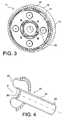
- the assemblyconstitutes an epicyclic gear train 17 of a conventional kind who is represented at the figure 3 .
- a low pressure turbine 18is located on the other side of the static casing 5. It comprises a third hollow shaft, which is a turbine shaft 19 used to support it by the static casing 5 by means of two bearings 20 and 21.
- the turbine shaft 19extends not far from the sun gear 16, from which it is however separated; the game between the planetary wheel 16 and the nearest bearing 21 is smaller than the distance between the two bearings 20 and 21.
- Itis a flexible sleeve 22 which serves to drive the sun gear 16 by connecting it to the rotor of the turbine 18.
- the flexible sleeve 22is connected to the turbine 18 by a bend 23 in a semicircle, not far from the connection to the turbine shaft 19.
- the bulk of the flexible sleeve 22is a substantially cylindrical surface 24 surrounded by the turbine shaft 19 by protruding at a third end 25 and serving as a support for the sun gear 16.
- the flexible sleeve 22is cut with oblong holes 26, represented at best on FIG. figure 4 and whose direction of extension is at an angle of 45 ° with respect to the axial direction X of the device, which corresponds to the axis of rotation of all the rotating parts (except the satellites 15).
- the sleeve 22is flexible due to a sufficiently small thickness, but it flexes especially to the section where it is notched.
- the turbine 18drives the sun gear 16 by the flexible sleeve 22, which induces rotations of the planet carrier 14 and the ring gear 10 and then the propellers 2 and 1, at predetermined speeds .
- the flexible sleeve 22has the ability to flex when radially unbalanced forces are imposed on the sun wheel 16.
- the first conical sleeve 8has the ability to flex at the location of the folds 9 when unbalanced efforts in the direction radial are exerted on the ring 10.
- the mounting of the planet carrier 14 to the propeller 2, by the second hollow shaft 4 and the second conical sleeve 13, on the other handis more rigid, which prevents excessive flexibility of the planetary gear train 17.
- the clearance 27 between the flexible sleeve 22 and the turbine shaft 19is weak at the location of the bearing 21 close to the planet wheel 16, which limits the deformations that can take the flexible sleeve 22 to reasonable values and in particular prevents it from breaking or the epicyclic train 17 becomes too loose.
- the flexible sleeve 22rotates at the same speed as the turbine shaft 19, no consequence is to be feared from the occurrence of this state of abutment which produces no friction.
Landscapes
- Engineering & Computer Science (AREA)
- Mechanical Engineering (AREA)
- General Engineering & Computer Science (AREA)
- Chemical & Material Sciences (AREA)
- Combustion & Propulsion (AREA)
- Aviation & Aerospace Engineering (AREA)
- Retarders (AREA)
Description
Translated fromFrenchLe sujet de l'invention est un dispositif d'entraînement d'une paire d'hélices contrarotatives à l'aide d'un train épicycloïdal selon la revendication 1.The subject of the invention is a device for driving a pair of counter-rotating propellers by means of an epicyclic gear train according to claim 1.
Les hélices contrarotatives sont déjà connues, et elles sont aussi envisagées pour certains aéronefs futurs afin de diminuer la consommation de carburant. La transmission de la puissance aux hélices peut comprendre un train épicycloïdal. La turbine de puissance (à basse pression) fait tourner un arbre mettant en rotation une roue planétaire (roue solaire) du train épicycloïdal. La roue planétaire entraîne elle-même des roues satellites, et un porte-satellites relié à l'arbre d'une des hélices. Le train épicycloïdal comprend encore une couronne extérieure, à denture interne et engrenant avec les satellites, et reliée à l'arbre de l'autre des hélices. Un choix judicieux des rapports de denture assure donc les rotations des hélices dans les deux sens opposés au rapport de vitesses voulu. Un tel agencement est décrit dans le document
Le train épicycloïdal a l'avantage d'être compact, mais il est soumis à des efforts élevés risquant d'endommager les dents. L'objet principal de l'invention est d'alléger ces efforts en lui permettant de transmettre essentiellement le couple moteur nécessaire à la transmission, tout en réduisant les efforts parasites tels que ceux qui proviennent de désalignements des roues dentées. Mais le dispositif doit tout de même résister à des efforts importants qui s'exercent sur lui dans certaines circonstances.The epicyclic train has the advantage of being compact, but it is subjected to high forces that may damage the teeth. The main object of the invention is to alleviate these forces by allowing it to transmit essentially the engine torque necessary for transmission, while reducing parasitic forces such as those resulting from misalignment of the gears. But the device must still withstand significant effort exerted on it in certain circumstances.
Cette double exigence est satisfaite avec l'invention qui, sous une forme générale, concerne un dispositif conforme à la revendication indépendante.This dual requirement is satisfied with the invention which, in a general form, relates to a device according to the independent claim.
Au lieu de soutenir la roue planétaire par l'arbre de turbine, affecté au support du rotor de la turbine sur le carter, on utilise le manchon souple, qui tolère des variations de position de son axe selon les efforts radiaux subis par la roue planétaire. Les efforts développés dans le train épicycloïdal diminuent donc. Toutefois, comme le jeu entre l'arbre de turbine fixe et le manchon souple est faible, une position de butée du manchon contre l'arbre est atteinte quand des forces plus importantes s'exercent dans la transmission. Une souplesse excessive, qui pourrait causer un mauvais fonctionnement du dispositif ou une destruction, en premier lieu par rupture du manchon, est empêchée, et les efforts importants qu'on peut rencontrer occasionnellement sont transmis à l'arbre de turbine rigide et résistant.Instead of supporting the sun wheel by the turbine shaft, assigned to the support of the rotor of the turbine on the housing, the flexible sleeve is used, which tolerates variations in position of its axis according to the radial forces undergone by the planetary wheel. . The forces developed in the planetary gear train therefore decrease. However, as the clearance between the turbine shaft fixed and the flexible sleeve is weak, an abutment position of the sleeve against the shaft is reached when greater forces are exerted in the transmission. Excessive flexibility, which could cause malfunction of the device or destruction, firstly by breakage of the sleeve, is prevented, and the occasional high loads that are occasionally encountered are transmitted to the rigid and strong turbine shaft.
Il est avantageux que l'arbre de turbine soit suffisamment long afin qu'il fournisse un support plus stable et que des porte-à-faux du manchon hors de l'arbre de turbine soient évités quand une butée est réalisée. Une distance entre deux roulements de support de l'arbre de turbine est donc supérieure à une distance présente entre un des roulements et la roue planétaire.It is advantageous that the turbine shaft is long enough to provide a more stable support and that overhangs of the sleeve out of the turbine shaft are avoided when a stop is made. A distance between two support bearings of the turbine shaft is greater than a distance between one of the bearings and the sun wheel.
L'agencement de l'invention doit être supérieur à celui du document
Une bonne souplesse du manchon est obtenue s'il forme un coude en demi-cercle à une extrémité de raccordement à la turbine, ou encore s'il comprend une section pourvue d'évidements oblongs, orientés avec un angle de 45° par rapport à une direction axiale du manchon, ce qui affaiblit localement le manchon d'une façon qui le rend plus souple en flexion, mais maintient sa résistance en torsion de manière à lui permettre de transmettre le couple requis. La section évidée peut être établie, quand le coude existe, à sa jonction à une portée principale du manchon.Good flexibility of the sleeve is obtained if it forms a semicircular elbow at a turbine connection end, or if it comprises a section provided with oblong recesses, oriented at an angle of 45 ° with respect to an axial direction of the sleeve, which locally weakens the sleeve in a manner that renders it more flexible in bending, but maintains its torsional strength so as to enable it to transmit the required torque. The recessed section can be established, when the bend exists, at its junction at a main bearing of the sleeve.
Une réduction plus grande des efforts est obtenue dans le train épicycloïdal si l'arbre lié à la couronne est plus souple que l'arbre lié au porte-satellites. L'ensemble lié au porte-satellites, comparativement rigide, est alors situé entre un ensemble de roue planétaire et un ensemble de couronne comparativement souples et qui se déforment indépendamment selon les efforts respectifs qu'ils subissent.A greater reduction of the forces is obtained in the epicyclic gear train if the shaft connected to the crown is more flexible than the shaft linked to the planet carrier. The assembly linked to the planet carrier, which is comparatively rigid, is then located between a planet wheel assembly and a comparatively flexible crown assembly which deform independently according to the respective forces they undergo.
L'invention sera maintenant décrite en liaison aux figures suivantes.
- la
figure 1 est une vue générale du dispositif selon l'invention ; - la
figure 2 illustre les alentours du train épicycloïdal; - la
figure 3 illustre le train épicycloïdal en vue de face ; - et la
figure 4 illustre une portion particulière du manchon souple.
- the
figure 1 is a general view of the device according to the invention; - the
figure 2 illustrates the surroundings of the epicyclic train; - the
figure 3 illustrates the epicyclic train in front view; - and the
figure 4 illustrates a particular portion of the flexible sleeve.
On se reporte aux
Une turbine à basse pression 18 est située de l'autre côté du carter statique 5. Elle comprend un troisième arbre creux, qui est un arbre de turbine 19 servant à la faire soutenir par le carter statique 5 à l'aide de deux roulements 20 et 21. L'arbre de turbine 19 s'étend non loin de la roue planétaire 16, dont il est cependant séparé; le jeu entre la roue planétaire 16 et le roulement 21 le plus proche est inférieur à la distance entre les deux roulements 20 et 21. C'est un manchon souple 22 qui sert à l'entraînement de la roue planétaire 16 en la reliant au rotor de la turbine 18. Le manchon souple 22 se raccorde à la turbine 18 par un coude 23 en demi-cercle, non loin du raccordement à l'arbre de turbine 19. L'essentiel du manchon souple 22 est une portée 24 essentiellement cylindrique entourée par l'arbre de turbine 19 en en dépassant à une troisième extrémité 25 et servant de support de la roue planétaire 16. A la jonction entre le coude 23 et la portée 24, le manchon souple 22 est entaillé de trous oblongs 26, représentés au mieux à la
Le fonctionnement du dispositif peut être décrit comme suit: la turbine 18 entraîne la roue planétaire 16 par le manchon souple 22, ce qui induit des rotations du porte-satellites 14 et de la couronne 10 puis des hélices 2 et 1, à des vitesses déterminées. Le manchon souple 22 a la faculté de fléchir quand des efforts déséquilibrés en direction radiale sont imposés sur la roue planétaire 16. De même, le premier manchon conique 8 a la faculté de fléchir à l'endroit des plis 9 quand des efforts déséquilibrés en direction radiale sont exercés sur la couronne 10. Le montage du porte-satellites 14 à l'hélice 2, par le deuxième arbre creux 4 et le deuxième manchon conique 13, est par contre plus rigide, ce qui empêche une souplesse excessive du train épicycloïdal 17. Et le jeu 27 entre le manchon souple 22 et l'arbre de turbine 19 est faible à l'endroit du roulement 21 proche de la roue planétaire 16, ce qui limite les déformations que peut prendre le manchon souple 22 à des valeurs raisonnables et empêche notamment qu'il ne se rompe ou que le train épicycloïdal 17 ne devienne trop lâche. Comme le manchon souple 22 tourne à la même vitesse que l'arbre de turbine 19, aucune conséquence n'est à redouter de l'occurrence de cet état de butée qui ne produit aucune friction.The operation of the device can be described as follows: the
Claims (5)
- Mechanism comprising a pair of contrarotating propellers (1, 2), a drive turbine (18), a shaft (19) connected to the turbine (18), a static casing (5) supporting the turbine (18) through the shaft (19) and two bearings (20, 21) in which the shaft extends and which support the shaft, a transmission comprising an epicyclic gear train (17) with a central planet gear (16) driven by the turbine, a planet pinion cage (14) driving one of the propellers (2) and fitted with satellite gears (15) engaging with the planet gear (16), and an outer ring engaging with the satellite gears (15) and driving the other propeller (1), a distance between one of the bearings (20, 21) and the planet gear (16) is less than a distance between the two bearings (20, 21),characterised in that it comprises a sleeve (22) connected to the turbine (18) and to the planet gear (16) to drive it, and the sleeve (22) comprises a surface (24) surrounded by the shaft (19), separated from it by a radial clearance (27) which limits deformations that can be applied to the sleeve at the location of the bearing (21) which is close to the planet gear (16), and the sleeve is more flexible in bending than the shaft, so as to deflect when unbalanced forces are imposed on the planet gear (16).
- Mechanism according to claim 1,characterised in that the sleeve (22) forms a semicircular bend (23) at one end of the connection to the turbine.
- Mechanism according to claim 1 or 2,characterised in that it comprises a section with oblong openings (26), oriented at an angle of 45° from an axial direction X of the sleeve (22).
- Mechanism according to claims 2 and 3,characterised in that the section is located at a junction of the bend (23), remote from the connection to the turbine, at the main, essentially cylindrical, contact surface (24) of the sleeve.
- Mechanism according to any one of claims 1 to 4,characterised in that a shaft (3, 8, 9) connecting the ring to said other propeller (1) is more flexible than a shaft (4, 13) connecting the planet pinion cage (14) to said one of the propellers (2).
Applications Claiming Priority (2)
| Application Number | Priority Date | Filing Date | Title |
|---|---|---|---|
| FR0951509AFR2943035B1 (en) | 2009-03-11 | 2009-03-11 | DEVICE FOR DRIVING A PAIRE OF CONTRAROTIVE PROPELLERS BY AN EPYCYCLOIDAL TRAIN |
| PCT/EP2010/052963WO2010102995A1 (en) | 2009-03-11 | 2010-03-09 | Device for driving a pair of counter-rotating propellers by means of an epicyclic gear train |
Publications (2)
| Publication Number | Publication Date |
|---|---|
| EP2406484A1 EP2406484A1 (en) | 2012-01-18 |
| EP2406484B1true EP2406484B1 (en) | 2013-07-24 |
Family
ID=40996477
Family Applications (1)
| Application Number | Title | Priority Date | Filing Date |
|---|---|---|---|
| EP10708757.9AActiveEP2406484B1 (en) | 2009-03-11 | 2010-03-09 | Device for driving a pair of counter-rotating propellers by means of an epicyclic gear train |
Country Status (9)
| Country | Link |
|---|---|
| US (1) | US8967950B2 (en) |
| EP (1) | EP2406484B1 (en) |
| JP (1) | JP5619786B2 (en) |
| CN (1) | CN102341588B (en) |
| BR (1) | BRPI1009788B1 (en) |
| CA (1) | CA2754175C (en) |
| FR (1) | FR2943035B1 (en) |
| RU (1) | RU2519531C2 (en) |
| WO (1) | WO2010102995A1 (en) |
Families Citing this family (21)
| Publication number | Priority date | Publication date | Assignee | Title |
|---|---|---|---|---|
| FR2977636B1 (en)* | 2011-07-06 | 2013-08-09 | Snecma | DEVICE FOR LUBRICATING A DOUBLE PROPELLER TURBOPROPULSOR INTERROBE BEARING BEARING |
| FR2979121B1 (en)* | 2011-08-18 | 2013-09-06 | Snecma | MECHANICAL TRANSMISSION DEVICE FOR THE ROTATION DRIVE OF THE CONTRAROTATIVE PROPELLERS OF A DOUBLE PROPELLER TURBOPROPULSOR. |
| US9182011B2 (en)* | 2012-10-01 | 2015-11-10 | United Technologies Corporation | Fan drive gear system flexible support features |
| US8951012B1 (en) | 2014-02-10 | 2015-02-10 | JVS Associates, Inc. | Contra-rotating axial fan transmission for evaporative and non-evaporative cooling and condensing equipment |
| WO2014113372A1 (en) | 2013-01-18 | 2014-07-24 | General Electric Company | Engine architecture with reverse rotation integral drive and vaneless turbine |
| FR3001498B1 (en) | 2013-01-30 | 2015-02-27 | Snecma | FIXED TURBOMACHINE RECEIVER PART COMPRISING A HOLDING ASSEMBLY IN SERVITUDE POSITION WITHIN A FIXED HOLLOW SHAFT |
| WO2014123804A2 (en) | 2013-02-09 | 2014-08-14 | Prime Datum Development Company, Llc | Direct-drive system for cooling system fans, exhaust blowers and pumps |
| FR3008155B1 (en)* | 2013-07-03 | 2016-10-07 | Snecma | MULTIPLE REDUCER TRANSMISSION BETWEEN A DRIVE SHAFT AND A PAIR OF COAXIAL PROPELLERS AT THIS TREE |
| FR3013766B1 (en)* | 2013-11-25 | 2017-11-10 | Snecma | TURBOMACHINE COMPRISING A SHAFT AND ASSOCIATED FOURREAU TUBE |
| WO2015094607A1 (en) | 2013-12-20 | 2015-06-25 | United Technologies Corporation | Geared turbofan with improved gear system maintainability |
| FR3016189B1 (en)* | 2014-01-07 | 2018-09-28 | Safran Aircraft Engines | EPICYCLOIDAL REDUCTION DEVICE FOR THE ROTATIONAL DRIVE OF BLADE ASSEMBLIES OF A REDUCING TURBOMACHINE |
| FR3024179B1 (en) | 2014-07-25 | 2016-08-26 | Snecma | PRESSURIZED AIR SUPPLY SYSTEM INSTALLED IN AN AIRCRAFT TURBOMACHINE HAVING SEALING MEANS |
| US10072571B2 (en)* | 2015-01-15 | 2018-09-11 | United Technologies Corporation | Gas turbine engine split torque fan drive gear system |
| FR3034465B1 (en) | 2015-04-03 | 2017-05-05 | Snecma | TURBOMOTEUR COMPRISING TWO DISTINCT VENTILATION FLOWS |
| GB201516570D0 (en) | 2015-09-18 | 2015-11-04 | Rolls Royce Plc | A Shafting Arrangement |
| US10094335B2 (en) | 2015-12-07 | 2018-10-09 | General Electric Company | Compliant shaft with a recursive configuration for turbine engines |
| CN106212406B (en)* | 2016-09-24 | 2022-12-02 | 威海奥美仿生医疗装备科技有限公司 | Reverse drive way inferior |
| EP3354847B1 (en)* | 2017-01-30 | 2023-03-08 | GE Avio S.r.l. | Flexible coupling shaft for turbine engine |
| EP3354882B1 (en)* | 2017-01-30 | 2021-03-17 | GE Avio S.r.l. | Method and system of connecting a turbine engine gearbox to engine core |
| EP3587774B1 (en)* | 2018-06-27 | 2025-05-07 | Rolls-Royce plc | Gas turbine |
| US12331683B2 (en) | 2023-09-29 | 2025-06-17 | Rtx Corporation | Bearing arrangement for turbine engine geartrain |
Family Cites Families (15)
| Publication number | Priority date | Publication date | Assignee | Title |
|---|---|---|---|---|
| US4817382A (en)* | 1985-12-31 | 1989-04-04 | The Boeing Company | Turboprop propulsion apparatus |
| JPS63183226A (en)* | 1987-01-26 | 1988-07-28 | Mitsubishi Heavy Ind Ltd | Double opposite rotating speed reduction gear |
| US4936748A (en)* | 1988-11-28 | 1990-06-26 | General Electric Company | Auxiliary power source in an unducted fan gas turbine engine |
| US5010729A (en) | 1989-01-03 | 1991-04-30 | General Electric Company | Geared counterrotating turbine/fan propulsion system |
| JPH0610603A (en)* | 1992-04-23 | 1994-01-18 | Praxair Technol Inc | Stress reducing type radial flow impeller blade |
| US5862706A (en)* | 1996-07-16 | 1999-01-26 | Mcdonnell Douglas Helicopter Company | Shaft deflection controller |
| DE19828562B4 (en)* | 1998-06-26 | 2005-09-08 | Mtu Aero Engines Gmbh | Engine with counter-rotating rotors |
| US7647779B2 (en)* | 2005-04-27 | 2010-01-19 | United Technologies Corporation | Compliant metal support for ceramic combustor liner in a gas turbine engine |
| RU2311554C2 (en)* | 2005-12-23 | 2007-11-27 | Открытое акционерное общество "Авиадвигатель" | Double-flow gas-turbine engine |
| US7591754B2 (en)* | 2006-03-22 | 2009-09-22 | United Technologies Corporation | Epicyclic gear train integral sun gear coupling design |
| US7926260B2 (en)* | 2006-07-05 | 2011-04-19 | United Technologies Corporation | Flexible shaft for gas turbine engine |
| US7694505B2 (en)* | 2006-07-31 | 2010-04-13 | General Electric Company | Gas turbine engine assembly and method of assembling same |
| FR2911930A1 (en)* | 2007-01-26 | 2008-08-01 | Snecma Sa | Turboprop for controlling pitch of blade, has groups of planet gearwheels, where one group is interposed between toothed rings of support and casing and other group is interposed between toothed rings of actuator annulus and control annulus |
| US7857519B2 (en)* | 2007-12-07 | 2010-12-28 | Pratt & Whitney Canada Corp. | Compact bearing support |
| FR2940247B1 (en) | 2008-12-19 | 2011-01-21 | Snecma | SYSTEM OF CONTRAROTATIVE PROPELLERS DRAWN BY AN EPICYCLOIDAL TRAIN PROVIDING A BALANCED TORQUE DISTRIBUTION BETWEEN THE TWO PROPELLERS |
- 2009
- 2009-03-11FRFR0951509Apatent/FR2943035B1/ennot_activeExpired - Fee Related
- 2010
- 2010-03-09USUS13/255,389patent/US8967950B2/enactiveActive
- 2010-03-09CACA2754175Apatent/CA2754175C/enactiveActive
- 2010-03-09JPJP2011553422Apatent/JP5619786B2/enactiveActive
- 2010-03-09RURU2011141090/06Apatent/RU2519531C2/enactive
- 2010-03-09WOPCT/EP2010/052963patent/WO2010102995A1/enactiveApplication Filing
- 2010-03-09BRBRPI1009788-0Apatent/BRPI1009788B1/enactiveIP Right Grant
- 2010-03-09EPEP10708757.9Apatent/EP2406484B1/enactiveActive
- 2010-03-09CNCN201080010196.2Apatent/CN102341588B/enactiveActive
Also Published As
| Publication number | Publication date |
|---|---|
| US8967950B2 (en) | 2015-03-03 |
| JP2012520410A (en) | 2012-09-06 |
| FR2943035B1 (en) | 2012-09-28 |
| RU2519531C2 (en) | 2014-06-10 |
| EP2406484A1 (en) | 2012-01-18 |
| CN102341588B (en) | 2014-07-23 |
| CA2754175A1 (en) | 2010-09-16 |
| CA2754175C (en) | 2016-12-20 |
| RU2011141090A (en) | 2013-04-20 |
| BRPI1009788B1 (en) | 2020-08-04 |
| WO2010102995A1 (en) | 2010-09-16 |
| JP5619786B2 (en) | 2014-11-05 |
| CN102341588A (en) | 2012-02-01 |
| BRPI1009788A2 (en) | 2016-03-08 |
| FR2943035A1 (en) | 2010-09-17 |
| US20120099988A1 (en) | 2012-04-26 |
Similar Documents
| Publication | Publication Date | Title |
|---|---|---|
| EP2406484B1 (en) | Device for driving a pair of counter-rotating propellers by means of an epicyclic gear train | |
| EP2521851B1 (en) | Contra-rotating propeller system for an aircraft turbine engine | |
| EP3102795B1 (en) | Turbine engine provided with a lubrication unit | |
| EP2396525B1 (en) | System of compact contra-rotating propellers | |
| EP3682139B1 (en) | Pivot for a sliding bearing | |
| EP3365544B1 (en) | Heat engine comprising a system for varying the compression ratio | |
| EP2619417B1 (en) | Sealing device | |
| FR3057850B1 (en) | MECHANICAL POWER TRANSMISSION SYSTEM, POWER TRANSMISSION BOX AND AIRCRAFT | |
| FR3124565A1 (en) | SATELLITE CARRIER FOR AN AIRCRAFT TURBOMACHINE SPEED REDUCER | |
| FR2994585A1 (en) | GEARBOX WITH REDUCED SIZE FOR AIRCRAFT TURBOMACHINE | |
| EP4348079B1 (en) | High power density radial reducer for turbofan | |
| FR2999237A1 (en) | GUIDANCE OF TURBOMACHINE TREES | |
| WO2023209291A1 (en) | Accessory gearbox and aircraft turbine engine comprising such a box | |
| EP4073356B1 (en) | Turbomachine having a contrarotating turbine for an aircraft | |
| EP0253034B1 (en) | Power transmission device between a motor means and a driven component | |
| FR2926866A1 (en) | DEVICE FOR REDUCING ROTATION SPEED BETWEEN TWO TREES. | |
| FR2583846A1 (en) | Device for transmitting movement between a motor means and a receiving member | |
| FR2727655A1 (en) | Electric or hydraulic epicyclic drive unit for electric vehicle | |
| EP3721118B1 (en) | Planetary gear train | |
| EP4208633B1 (en) | Assembly for an aircraft turbine engine, comprising means for the axial and radial retention of a fan | |
| EP3492763B1 (en) | Mechanical power transmission system, power transmission box and aircraft | |
| FR3002980A1 (en) | LUBRICATION GROUP FOR A TURBOMACHINE | |
| FR2942861A1 (en) | HELICOIDAL TOOTHING MOTION TRANSMISSION SYSTEM | |
| FR2599802A1 (en) | Anti-backlash reduction gear especially for the articulations of manipulating arms |
Legal Events
| Date | Code | Title | Description |
|---|---|---|---|
| PUAI | Public reference made under article 153(3) epc to a published international application that has entered the european phase | Free format text:ORIGINAL CODE: 0009012 | |
| 17P | Request for examination filed | Effective date:20110919 | |
| AK | Designated contracting states | Kind code of ref document:A1 Designated state(s):AT BE BG CH CY CZ DE DK EE ES FI FR GB GR HR HU IE IS IT LI LT LU LV MC MK MT NL NO PL PT RO SE SI SK SM TR | |
| DAX | Request for extension of the european patent (deleted) | ||
| 17Q | First examination report despatched | Effective date:20120821 | |
| REG | Reference to a national code | Ref country code:DE Ref legal event code:R079 Ref document number:602010008817 Country of ref document:DE Free format text:PREVIOUS MAIN CLASS: F02K0003072000 Ipc:B64D0035060000 | |
| GRAP | Despatch of communication of intention to grant a patent | Free format text:ORIGINAL CODE: EPIDOSNIGR1 | |
| RIC1 | Information provided on ipc code assigned before grant | Ipc:F02K 3/072 20060101ALI20130118BHEP Ipc:B64D 35/06 20060101AFI20130118BHEP Ipc:F01D 5/02 20060101ALI20130118BHEP Ipc:F02C 7/36 20060101ALI20130118BHEP Ipc:F02C 3/10 20060101ALI20130118BHEP Ipc:F02C 3/067 20060101ALI20130118BHEP | |
| GRAS | Grant fee paid | Free format text:ORIGINAL CODE: EPIDOSNIGR3 | |
| GRAA | (expected) grant | Free format text:ORIGINAL CODE: 0009210 | |
| AK | Designated contracting states | Kind code of ref document:B1 Designated state(s):AT BE BG CH CY CZ DE DK EE ES FI FR GB GR HR HU IE IS IT LI LT LU LV MC MK MT NL NO PL PT RO SE SI SK SM TR | |
| REG | Reference to a national code | Ref country code:GB Ref legal event code:FG4D Free format text:NOT ENGLISH | |
| REG | Reference to a national code | Ref country code:CH Ref legal event code:EP | |
| REG | Reference to a national code | Ref country code:AT Ref legal event code:REF Ref document number:623251 Country of ref document:AT Kind code of ref document:T Effective date:20130815 | |
| REG | Reference to a national code | Ref country code:IE Ref legal event code:FG4D Free format text:LANGUAGE OF EP DOCUMENT: FRENCH | |
| REG | Reference to a national code | Ref country code:DE Ref legal event code:R096 Ref document number:602010008817 Country of ref document:DE Effective date:20130919 | |
| REG | Reference to a national code | Ref country code:SE Ref legal event code:TRGR | |
| REG | Reference to a national code | Ref country code:AT Ref legal event code:MK05 Ref document number:623251 Country of ref document:AT Kind code of ref document:T Effective date:20130724 | |
| REG | Reference to a national code | Ref country code:NL Ref legal event code:VDEP Effective date:20130724 | |
| REG | Reference to a national code | Ref country code:LT Ref legal event code:MG4D | |
| PG25 | Lapsed in a contracting state [announced via postgrant information from national office to epo] | Ref country code:CY Free format text:LAPSE BECAUSE OF FAILURE TO SUBMIT A TRANSLATION OF THE DESCRIPTION OR TO PAY THE FEE WITHIN THE PRESCRIBED TIME-LIMIT Effective date:20130807 Ref country code:NO Free format text:LAPSE BECAUSE OF FAILURE TO SUBMIT A TRANSLATION OF THE DESCRIPTION OR TO PAY THE FEE WITHIN THE PRESCRIBED TIME-LIMIT Effective date:20131024 Ref country code:HR Free format text:LAPSE BECAUSE OF FAILURE TO SUBMIT A TRANSLATION OF THE DESCRIPTION OR TO PAY THE FEE WITHIN THE PRESCRIBED TIME-LIMIT Effective date:20130724 Ref country code:AT Free format text:LAPSE BECAUSE OF FAILURE TO SUBMIT A TRANSLATION OF THE DESCRIPTION OR TO PAY THE FEE WITHIN THE PRESCRIBED TIME-LIMIT Effective date:20130724 Ref country code:IS Free format text:LAPSE BECAUSE OF FAILURE TO SUBMIT A TRANSLATION OF THE DESCRIPTION OR TO PAY THE FEE WITHIN THE PRESCRIBED TIME-LIMIT Effective date:20131124 Ref country code:PT Free format text:LAPSE BECAUSE OF FAILURE TO SUBMIT A TRANSLATION OF THE DESCRIPTION OR TO PAY THE FEE WITHIN THE PRESCRIBED TIME-LIMIT Effective date:20131125 Ref country code:LT Free format text:LAPSE BECAUSE OF FAILURE TO SUBMIT A TRANSLATION OF THE DESCRIPTION OR TO PAY THE FEE WITHIN THE PRESCRIBED TIME-LIMIT Effective date:20130724 | |
| PG25 | Lapsed in a contracting state [announced via postgrant information from national office to epo] | Ref country code:GR Free format text:LAPSE BECAUSE OF FAILURE TO SUBMIT A TRANSLATION OF THE DESCRIPTION OR TO PAY THE FEE WITHIN THE PRESCRIBED TIME-LIMIT Effective date:20131025 Ref country code:PL Free format text:LAPSE BECAUSE OF FAILURE TO SUBMIT A TRANSLATION OF THE DESCRIPTION OR TO PAY THE FEE WITHIN THE PRESCRIBED TIME-LIMIT Effective date:20130724 Ref country code:LV Free format text:LAPSE BECAUSE OF FAILURE TO SUBMIT A TRANSLATION OF THE DESCRIPTION OR TO PAY THE FEE WITHIN THE PRESCRIBED TIME-LIMIT Effective date:20130724 Ref country code:NL Free format text:LAPSE BECAUSE OF FAILURE TO SUBMIT A TRANSLATION OF THE DESCRIPTION OR TO PAY THE FEE WITHIN THE PRESCRIBED TIME-LIMIT Effective date:20130724 Ref country code:SI Free format text:LAPSE BECAUSE OF FAILURE TO SUBMIT A TRANSLATION OF THE DESCRIPTION OR TO PAY THE FEE WITHIN THE PRESCRIBED TIME-LIMIT Effective date:20130724 Ref country code:FI Free format text:LAPSE BECAUSE OF FAILURE TO SUBMIT A TRANSLATION OF THE DESCRIPTION OR TO PAY THE FEE WITHIN THE PRESCRIBED TIME-LIMIT Effective date:20130724 | |
| PG25 | Lapsed in a contracting state [announced via postgrant information from national office to epo] | Ref country code:CY Free format text:LAPSE BECAUSE OF FAILURE TO SUBMIT A TRANSLATION OF THE DESCRIPTION OR TO PAY THE FEE WITHIN THE PRESCRIBED TIME-LIMIT Effective date:20130724 | |
| PG25 | Lapsed in a contracting state [announced via postgrant information from national office to epo] | Ref country code:DK Free format text:LAPSE BECAUSE OF FAILURE TO SUBMIT A TRANSLATION OF THE DESCRIPTION OR TO PAY THE FEE WITHIN THE PRESCRIBED TIME-LIMIT Effective date:20130724 Ref country code:EE Free format text:LAPSE BECAUSE OF FAILURE TO SUBMIT A TRANSLATION OF THE DESCRIPTION OR TO PAY THE FEE WITHIN THE PRESCRIBED TIME-LIMIT Effective date:20130724 Ref country code:CZ Free format text:LAPSE BECAUSE OF FAILURE TO SUBMIT A TRANSLATION OF THE DESCRIPTION OR TO PAY THE FEE WITHIN THE PRESCRIBED TIME-LIMIT Effective date:20130724 Ref country code:RO Free format text:LAPSE BECAUSE OF FAILURE TO SUBMIT A TRANSLATION OF THE DESCRIPTION OR TO PAY THE FEE WITHIN THE PRESCRIBED TIME-LIMIT Effective date:20130724 Ref country code:SK Free format text:LAPSE BECAUSE OF FAILURE TO SUBMIT A TRANSLATION OF THE DESCRIPTION OR TO PAY THE FEE WITHIN THE PRESCRIBED TIME-LIMIT Effective date:20130724 | |
| PG25 | Lapsed in a contracting state [announced via postgrant information from national office to epo] | Ref country code:ES Free format text:LAPSE BECAUSE OF FAILURE TO SUBMIT A TRANSLATION OF THE DESCRIPTION OR TO PAY THE FEE WITHIN THE PRESCRIBED TIME-LIMIT Effective date:20130724 | |
| PLBE | No opposition filed within time limit | Free format text:ORIGINAL CODE: 0009261 | |
| STAA | Information on the status of an ep patent application or granted ep patent | Free format text:STATUS: NO OPPOSITION FILED WITHIN TIME LIMIT | |
| 26N | No opposition filed | Effective date:20140425 | |
| REG | Reference to a national code | Ref country code:DE Ref legal event code:R097 Ref document number:602010008817 Country of ref document:DE Effective date:20140425 | |
| PG25 | Lapsed in a contracting state [announced via postgrant information from national office to epo] | Ref country code:LU Free format text:LAPSE BECAUSE OF FAILURE TO SUBMIT A TRANSLATION OF THE DESCRIPTION OR TO PAY THE FEE WITHIN THE PRESCRIBED TIME-LIMIT Effective date:20140309 | |
| REG | Reference to a national code | Ref country code:CH Ref legal event code:PL | |
| REG | Reference to a national code | Ref country code:IE Ref legal event code:MM4A | |
| PG25 | Lapsed in a contracting state [announced via postgrant information from national office to epo] | Ref country code:LI Free format text:LAPSE BECAUSE OF NON-PAYMENT OF DUE FEES Effective date:20140331 Ref country code:CH Free format text:LAPSE BECAUSE OF NON-PAYMENT OF DUE FEES Effective date:20140331 Ref country code:IE Free format text:LAPSE BECAUSE OF NON-PAYMENT OF DUE FEES Effective date:20140309 | |
| REG | Reference to a national code | Ref country code:FR Ref legal event code:PLFP Year of fee payment:7 | |
| PG25 | Lapsed in a contracting state [announced via postgrant information from national office to epo] | Ref country code:MT Free format text:LAPSE BECAUSE OF FAILURE TO SUBMIT A TRANSLATION OF THE DESCRIPTION OR TO PAY THE FEE WITHIN THE PRESCRIBED TIME-LIMIT Effective date:20130724 | |
| PG25 | Lapsed in a contracting state [announced via postgrant information from national office to epo] | Ref country code:SM Free format text:LAPSE BECAUSE OF FAILURE TO SUBMIT A TRANSLATION OF THE DESCRIPTION OR TO PAY THE FEE WITHIN THE PRESCRIBED TIME-LIMIT Effective date:20130724 | |
| PG25 | Lapsed in a contracting state [announced via postgrant information from national office to epo] | Ref country code:MC Free format text:LAPSE BECAUSE OF FAILURE TO SUBMIT A TRANSLATION OF THE DESCRIPTION OR TO PAY THE FEE WITHIN THE PRESCRIBED TIME-LIMIT Effective date:20130724 | |
| PG25 | Lapsed in a contracting state [announced via postgrant information from national office to epo] | Ref country code:BG Free format text:LAPSE BECAUSE OF FAILURE TO SUBMIT A TRANSLATION OF THE DESCRIPTION OR TO PAY THE FEE WITHIN THE PRESCRIBED TIME-LIMIT Effective date:20130724 | |
| PG25 | Lapsed in a contracting state [announced via postgrant information from national office to epo] | Ref country code:BE Free format text:LAPSE BECAUSE OF FAILURE TO SUBMIT A TRANSLATION OF THE DESCRIPTION OR TO PAY THE FEE WITHIN THE PRESCRIBED TIME-LIMIT Effective date:20140331 Ref country code:HU Free format text:LAPSE BECAUSE OF FAILURE TO SUBMIT A TRANSLATION OF THE DESCRIPTION OR TO PAY THE FEE WITHIN THE PRESCRIBED TIME-LIMIT; INVALID AB INITIO Effective date:20100309 Ref country code:TR Free format text:LAPSE BECAUSE OF FAILURE TO SUBMIT A TRANSLATION OF THE DESCRIPTION OR TO PAY THE FEE WITHIN THE PRESCRIBED TIME-LIMIT Effective date:20130724 | |
| REG | Reference to a national code | Ref country code:FR Ref legal event code:PLFP Year of fee payment:8 | |
| REG | Reference to a national code | Ref country code:FR Ref legal event code:PLFP Year of fee payment:9 | |
| PG25 | Lapsed in a contracting state [announced via postgrant information from national office to epo] | Ref country code:MK Free format text:LAPSE BECAUSE OF FAILURE TO SUBMIT A TRANSLATION OF THE DESCRIPTION OR TO PAY THE FEE WITHIN THE PRESCRIBED TIME-LIMIT Effective date:20130724 | |
| REG | Reference to a national code | Ref country code:FR Ref legal event code:CD Owner name:SAFRAN AIRCRAFT ENGINES, FR Effective date:20170719 | |
| PGFP | Annual fee paid to national office [announced via postgrant information from national office to epo] | Ref country code:SE Payment date:20240220 Year of fee payment:15 | |
| PGFP | Annual fee paid to national office [announced via postgrant information from national office to epo] | Ref country code:DE Payment date:20250218 Year of fee payment:16 | |
| PGFP | Annual fee paid to national office [announced via postgrant information from national office to epo] | Ref country code:FR Payment date:20250218 Year of fee payment:16 | |
| PGFP | Annual fee paid to national office [announced via postgrant information from national office to epo] | Ref country code:IT Payment date:20250218 Year of fee payment:16 Ref country code:GB Payment date:20250221 Year of fee payment:16 |