EP2405819B1 - Rotational intravascular ultrasound probe with an active spinning element - Google Patents
Rotational intravascular ultrasound probe with an active spinning elementDownload PDFInfo
- Publication number
- EP2405819B1 EP2405819B1EP10751228.7AEP10751228AEP2405819B1EP 2405819 B1EP2405819 B1EP 2405819B1EP 10751228 AEP10751228 AEP 10751228AEP 2405819 B1EP2405819 B1EP 2405819B1
- Authority
- EP
- European Patent Office
- Prior art keywords
- transducer
- spinning element
- connector
- interface module
- printed circuit
- Prior art date
- Legal status (The legal status is an assumption and is not a legal conclusion. Google has not performed a legal analysis and makes no representation as to the accuracy of the status listed.)
- Active
Links
- 238000009987spinningMethods0.000titleclaimsdescription96
- 239000000523sampleSubstances0.000titleclaimsdescription61
- 238000002608intravascular ultrasoundMethods0.000titleclaimsdescription50
- 230000003287optical effectEffects0.000claimsdescription17
- 238000004891communicationMethods0.000claimsdescription12
- 230000000295complement effectEffects0.000claimsdescription7
- 238000003780insertionMethods0.000claimsdescription5
- 230000037431insertionEffects0.000claimsdescription5
- 210000005166vasculatureAnatomy0.000claimsdescription4
- 238000005516engineering processMethods0.000description33
- 238000002604ultrasonographyMethods0.000description24
- 238000004804windingMethods0.000description20
- 239000008280bloodSubstances0.000description12
- 210000004369bloodAnatomy0.000description12
- 230000007246mechanismEffects0.000description9
- 238000012545processingMethods0.000description7
- 239000002033PVDF binderSubstances0.000description6
- 230000008901benefitEffects0.000description6
- 238000000034methodMethods0.000description6
- 229920002981polyvinylidene fluoridePolymers0.000description6
- 238000012546transferMethods0.000description6
- 238000003384imaging methodMethods0.000description5
- 230000013011matingEffects0.000description5
- 230000037361pathwayEffects0.000description5
- 239000012530fluidSubstances0.000description4
- 238000004519manufacturing processMethods0.000description4
- XUIMIQQOPSSXEZ-UHFFFAOYSA-NSiliconChemical compound[Si]XUIMIQQOPSSXEZ-UHFFFAOYSA-N0.000description3
- 230000005540biological transmissionEffects0.000description3
- 238000012512characterization methodMethods0.000description3
- 230000019491signal transductionEffects0.000description3
- 229910052710siliconInorganic materials0.000description3
- 239000010703siliconSubstances0.000description3
- 239000000758substrateSubstances0.000description3
- 239000013078crystalSubstances0.000description2
- 230000004069differentiationEffects0.000description2
- 238000002592echocardiographyMethods0.000description2
- 229920000642polymerPolymers0.000description2
- 230000009467reductionEffects0.000description2
- 239000004065semiconductorSubstances0.000description2
- 239000007787solidSubstances0.000description2
- 206010060965Arterial stenosisDiseases0.000description1
- 201000001320AtherosclerosisDiseases0.000description1
- 208000037260Atherosclerotic PlaqueDiseases0.000description1
- 239000004593EpoxySubstances0.000description1
- FAPWRFPIFSIZLT-UHFFFAOYSA-MSodium chlorideChemical compound[Na+].[Cl-]FAPWRFPIFSIZLT-UHFFFAOYSA-M0.000description1
- 208000007536ThrombosisDiseases0.000description1
- 230000002411adverseEffects0.000description1
- 238000004458analytical methodMethods0.000description1
- 210000003484anatomyAnatomy0.000description1
- 238000002583angiographyMethods0.000description1
- 238000003491arrayMethods0.000description1
- 210000004204blood vesselAnatomy0.000description1
- 239000000919ceramicSubstances0.000description1
- 239000002131composite materialSubstances0.000description1
- 230000008878couplingEffects0.000description1
- 238000010168coupling processMethods0.000description1
- 238000005859coupling reactionMethods0.000description1
- 230000007547defectEffects0.000description1
- 230000001419dependent effectEffects0.000description1
- 238000000151depositionMethods0.000description1
- 238000013461designMethods0.000description1
- 238000001514detection methodMethods0.000description1
- 238000003745diagnosisMethods0.000description1
- 238000002059diagnostic imagingMethods0.000description1
- 238000002405diagnostic procedureMethods0.000description1
- 230000000916dilatatory effectEffects0.000description1
- 201000010099diseaseDiseases0.000description1
- 208000037265diseases, disorders, signs and symptomsDiseases0.000description1
- 239000003814drugSubstances0.000description1
- 229940079593drugDrugs0.000description1
- 238000012377drug deliveryMethods0.000description1
- 230000009977dual effectEffects0.000description1
- 230000005284excitationEffects0.000description1
- 230000010365information processingEffects0.000description1
- 239000000314lubricantSubstances0.000description1
- 208000010125myocardial infarctionDiseases0.000description1
- 230000035515penetrationEffects0.000description1
- 230000002093peripheral effectEffects0.000description1
- 230000004044responseEffects0.000description1
- 239000011780sodium chlorideSubstances0.000description1
- 230000002123temporal effectEffects0.000description1
Images


Classifications
- A—HUMAN NECESSITIES
- A61—MEDICAL OR VETERINARY SCIENCE; HYGIENE
- A61B—DIAGNOSIS; SURGERY; IDENTIFICATION
- A61B8/00—Diagnosis using ultrasonic, sonic or infrasonic waves
- A61B8/12—Diagnosis using ultrasonic, sonic or infrasonic waves in body cavities or body tracts, e.g. by using catheters
- A—HUMAN NECESSITIES
- A61—MEDICAL OR VETERINARY SCIENCE; HYGIENE
- A61B—DIAGNOSIS; SURGERY; IDENTIFICATION
- A61B8/00—Diagnosis using ultrasonic, sonic or infrasonic waves
- A61B8/44—Constructional features of the ultrasonic, sonic or infrasonic diagnostic device
- A61B8/4444—Constructional features of the ultrasonic, sonic or infrasonic diagnostic device related to the probe
- A61B8/445—Details of catheter construction
- A—HUMAN NECESSITIES
- A61—MEDICAL OR VETERINARY SCIENCE; HYGIENE
- A61B—DIAGNOSIS; SURGERY; IDENTIFICATION
- A61B8/00—Diagnosis using ultrasonic, sonic or infrasonic waves
- A61B8/44—Constructional features of the ultrasonic, sonic or infrasonic diagnostic device
- A61B8/4444—Constructional features of the ultrasonic, sonic or infrasonic diagnostic device related to the probe
- A61B8/4461—Features of the scanning mechanism, e.g. for moving the transducer within the housing of the probe
- A—HUMAN NECESSITIES
- A61—MEDICAL OR VETERINARY SCIENCE; HYGIENE
- A61B—DIAGNOSIS; SURGERY; IDENTIFICATION
- A61B8/00—Diagnosis using ultrasonic, sonic or infrasonic waves
- A61B8/44—Constructional features of the ultrasonic, sonic or infrasonic diagnostic device
- A61B8/4483—Constructional features of the ultrasonic, sonic or infrasonic diagnostic device characterised by features of the ultrasound transducer
- A61B8/4488—Constructional features of the ultrasonic, sonic or infrasonic diagnostic device characterised by features of the ultrasound transducer the transducer being a phased array
- A—HUMAN NECESSITIES
- A61—MEDICAL OR VETERINARY SCIENCE; HYGIENE
- A61B—DIAGNOSIS; SURGERY; IDENTIFICATION
- A61B8/00—Diagnosis using ultrasonic, sonic or infrasonic waves
- A61B8/52—Devices using data or image processing specially adapted for diagnosis using ultrasonic, sonic or infrasonic waves
- A—HUMAN NECESSITIES
- A61—MEDICAL OR VETERINARY SCIENCE; HYGIENE
- A61B—DIAGNOSIS; SURGERY; IDENTIFICATION
- A61B8/00—Diagnosis using ultrasonic, sonic or infrasonic waves
- A61B8/54—Control of the diagnostic device
- A—HUMAN NECESSITIES
- A61—MEDICAL OR VETERINARY SCIENCE; HYGIENE
- A61B—DIAGNOSIS; SURGERY; IDENTIFICATION
- A61B8/00—Diagnosis using ultrasonic, sonic or infrasonic waves
- A61B8/56—Details of data transmission or power supply
- G—PHYSICS
- G10—MUSICAL INSTRUMENTS; ACOUSTICS
- G10K—SOUND-PRODUCING DEVICES; METHODS OR DEVICES FOR PROTECTING AGAINST, OR FOR DAMPING, NOISE OR OTHER ACOUSTIC WAVES IN GENERAL; ACOUSTICS NOT OTHERWISE PROVIDED FOR
- G10K11/00—Methods or devices for transmitting, conducting or directing sound in general; Methods or devices for protecting against, or for damping, noise or other acoustic waves in general
- G10K11/18—Methods or devices for transmitting, conducting or directing sound
- G10K11/26—Sound-focusing or directing, e.g. scanning
- G10K11/35—Sound-focusing or directing, e.g. scanning using mechanical steering of transducers or their beams
- G10K11/352—Sound-focusing or directing, e.g. scanning using mechanical steering of transducers or their beams by moving the transducer
- G10K11/355—Arcuate movement
- A—HUMAN NECESSITIES
- A61—MEDICAL OR VETERINARY SCIENCE; HYGIENE
- A61B—DIAGNOSIS; SURGERY; IDENTIFICATION
- A61B8/00—Diagnosis using ultrasonic, sonic or infrasonic waves
- A61B8/44—Constructional features of the ultrasonic, sonic or infrasonic diagnostic device
- A61B8/4444—Constructional features of the ultrasonic, sonic or infrasonic diagnostic device related to the probe
- A61B8/4472—Wireless probes
Definitions
- Intravascular Ultrasoundhas become an important interventional diagnostic procedure for imaging atherosclerosis and other vessel diseases and defects.
- an IVUS catheteris threaded over a guidewire into a blood vessel of interest, and images are acquired of the atherosclerotic plaque and surrounding area using ultrasonic echoes.
- This informationis much more descriptive than the traditional standard of angiography, which shows only a two-dimensional shadow of the vessel lumen.
- IVUSSome of the key applications of IVUS include: determining a correct diameter and length of a stent to choose for dilating an arterial stenosis, verifying that a post-stenting diameter and luminal cross-section area are adequate, verifying that a stent is well apposed against a vessel wall to minimize thrombosis and optimize drug delivery (in the case of a drug eluting stent) and identifying an exact location of side-branch vessels.
- new techniquessuch as virtual histology (RF signal-based tissue characterization) show promise of aiding identification of vulnerable plaque (i.e., plaque which is prone to rupture and lead to onset of a heart attack).
- IVUS cathetersThere are two types of IVUS catheters commonly in use: mechanical/rotational IVUS catheters and solid state catheters.
- a rotational IVUS cathetera single transducer consisting of a piezoelectric crystal is rotated at approximately 1800 revolutions per minute while the element is intermittently excited with an electrical pulse. This excitation causes the element to vibrate at a frequency dependent upon the particulars of the transducer design. Depending on the dimensions and characteristics of the transducer, this operating frequency is typically in the range of 8 to 50MHz. In general terms, a higher frequency of operation provides better resolution and a smaller catheter, but at the expense of reduced depth of penetration and increased echoes from the blood (making the image more difficult to interpret). A lower frequency of operation is more suitable for IVUS imaging in larger vessels or within the chambers of the heart.
- the rotational IVUS catheterhas a drive shaft disposed within the catheter body.
- the transduceris attached to the distal end of the drive shaft.
- the typical single element piezoelectric transducerrequires only two electrical leads, with this pair of leads serving two separate purposes: (1) delivering the intermittent electrical transmit pulses to the transducer, and (2) delivering the received electrical echo signals from the transducer to the receiver amplifier (during the intervals between transmit pulses).
- the IVUS catheteris removably coupled to an interface module, which controls the rotation of the drive shaft within the catheter body and contains the transmitter and receiver circuitry for the transducer. Because the transducer is on a rotating drive shaft and the transmitter and receiver circuitry is stationary, a device must be utilized to carry the transmit pulse and received echo across a rotating interface.
- a rotary transformerwhich comprises two halves, separated by a narrow air gap that permits electrical coupling between the primary and secondary windings of the transformer while allowing relative motion (rotation) between the two halves.
- the spinning elementtransducer, electrical leads, and driveshaft
- the stationary transmitter and receiver circuitry contained in the interface moduleare attached to the stationary portion of the rotary transformer.
- the other type of IVUS catheteris a solid state (or phased array) catheter.
- This catheterhas no rotating parts, but instead includes an array of transducer elements (for example 64 elements), arrayed in a cylinder around the circumference of the catheter body.
- the individual elementsare fired in a specific sequence under the control of several small integrated circuits mounted in the tip of the catheter, adjacent to the transducer array.
- the sequence of transmit pulses interspersed with receipt of the echo signalsprovides the ultrasound data required to reconstruct a complete cross-sectional image of the vessel, similar in nature to that provided by a rotational IVUS device.
- Advanced transducer technologiesalso offer the potential for improved beam characteristics, either by providing a focused transducer aperture (instead of the planar, unfocused aperture commonly used), or by implementing dynamically variable focus with an array of transducer elements (in place of the traditional single transducer element).
- Document US20060084875A1discloses systems and methods that allow for the application of a bias voltage to one or more transducers implemented within a medical ultrasound imaging system.
- Bias circuitryis placed within an imaging device and used to apply a DC bias to one or more transducers requiring a DC bias to operate.
- the one or more transducerscan be fabricated in a semiconductor manufacturing process and integrated with the bias circuitry on a common semiconductor substrate. Also provided is a method for operating the one or more transducers and bias circuitry using a communication channel having two signal lines.
- the present inventionprovides the enabling technology allowing advanced transducer technology to be introduced into a rotational IVUS catheter. This in turn will provide improved image quality and support advanced signal processing to facilitate more accurate diagnosis of the medical condition within the vessel. All of this can be achieved in a cost-effective way, possibly at a lower cost than the conventional technology.
- Embodiments of an intravascular ultrasound probeare disclosed herein.
- the probehas features for utilizing an advanced transducer technology on a rotating transducer shaft.
- the probeaccommodates the transmission of the multitude of signals across the boundary between the rotary and stationary components of the probe required to support an advanced transducer technology.
- These advanced transducer technologiesoffer the potential for increased bandwidth, improved beam profiles, better signal to noise ratio, reduced manufacturing costs, advanced tissue characterization algorithms, and other desirable features.
- the inclusion of electronic components on the spinning side of the probecan be highly advantageous in terms of preserving maximum signal to noise ratio and signal fidelity, along with other performance benefits.
- a rotational intravascular ultrasound probe for insertion into a vasculatureis described as claimed in claim 1.
- an interface module for a rotational intravascular ultrasound probe for insertion into a vasculatureis described as claimed in claim 7.
- an active spinning elementcan increase the number of signal paths available for the operation of the transducer so that advanced transducer technologies, such as PMUT (Piezoelectric Micromachined Ultrasonic Transducer) and CMUT (Capacitive Micromachined Ultrasonic Transducer), can be utilized with a rotational IVUS probe.
- an active spinning elementcan include active electronics on the rotary side of the probe.
- the probe 100comprises a catheter 101 having a catheter body 102 and a transducer shaft 104.
- the catheter body 102is flexible and has both a proximal end portion 106 and a distal end portion 108.
- the catheter body 102is a sheath surrounding the transducer shaft 104.
- the catheter body 102 in Fig. 1is illustrated as visually transparent such that the transducer shaft 104 disposed therein can be seen, although it will be appreciated that the catheter body 102 may or may not be visually transparent.
- the transducer shaft 104is flushed with a sterile fluid, such as saline, within the catheter body 102.
- a sterile fluidsuch as saline
- the fluidserves to eliminate the presence of air pockets around the transducer shaft 104 that adversely affect image quality.
- the fluidcan also act as a lubricant.
- the transducer shaft 104has a proximal end portion 110 disposed within the proximal end portion 106 of the catheter body 102 and a distal end portion 112 disposed within the distal end portion 108 of the catheter body 102.
- the distal end portion 108 of the catheter body 102 and the distal end portion 112 of the transducer shaft 104are inserted into a patient during the operation of the probe 100.
- the usable length of the probe 100(the portion that can be inserted into a patient) can be any suitable length and can be varied depending upon the application.
- the distal end portion 112 of the transducer shaft 104includes a transducer subassembly 118.
- the proximal end portion 106 of the catheter body 102 and the proximal end portion 110 of the transducer shaft 104are connected to an interface module 114 (sometimes referred to as a patient interface module or PIM).
- the proximal end portions 106, 110are fitted with a catheter hub 116 that is removably connected to the interface module 114.
- the rotation of the transducer shaft 104 within the catheter body 102is controlled by the interface module 114, which provides a plurality of user interface controls that can be manipulated by a user.
- the interface module 114also communicates with the transducer subassembly 118 by sending and receiving electrical signals to and from the transducer subassembly 118 via wires within the transducer shaft 104.
- the interface module 114can receive, analyze, and/or display information received through the transducer shaft 104. It will be appreciated that any suitable functionality, controls, information processing and analysis, and display can be incorporated into the interface module 114.
- the transducer shaft 104includes a transducer subassembly 118, a transducer housing 120, and a drive cable 122.
- the transducer subassembly 118is coupled to the transducer housing 120.
- the transducer housing 120is attached to the drive cable 122 at the distal end portion 112 of the transducer shaft 104.
- the drive cable 122is rotated within the catheter body 102 via the interface module 114 to rotate the transducer housing 120 and the transducer subassembly 118.
- the transducer subassembly 118can be of any suitable type, including but not limited to one or more advanced transducer technologies such as PMUT or CMUT.
- the transducer subassembly 118can include either a single transducer or an array.
- Fig. 2shows a rotational IVUS probe 200 utilizing a common spinning element 232.
- the probe 200has a catheter 201 with a catheter body 202 and a transducer shaft 204.
- the catheter hub 216is near the proximal end portion 206 of the catheter body 202 and the proximal end portion 210 of the transducer shaft 204.
- the catheter hub 216includes a stationary hub housing 224, a dog 226, a connector 228, and bearings 230.
- the dog 226mates with a spinning element 232 for alignment of the hub 216 with the interface module 214 and torque transmission to the transducer shaft 204.
- the dog 226rotates within the hub housing 224 utilizing the bearings 230.
- the connector 228 in this figureis coaxial. The connector 228 rotates with the spinning element 232, described further herein.
- the interior of the interface module 214includes a motor 236, a motor shaft 238, a printed circuit board (PCB) 240, the spinning element 232, and any other suitable components for the operation of the IVUS probe 200.
- the motor 236is connected to the motor shaft 238 to rotate the spinning element 232.
- the printed circuit board 240can have any suitable number and type of electronic components 242, including but not limited to the transmitter and the receiver for the transducer.
- the spinning element 232has a complimentary connector 244 for mating with the connector 228 on the catheter hub 216. As shown, the spinning element 232 is coupled to a rotary portion 248 of a rotary transformer 246. The rotary portion 248 of the transformer 246 passes the signals to and from a stationary portion 250 of the transformer 246. The stationary portion 250 of the transformer 246 is wired to the transmitter and receiver circuitry on the printed circuit board 240.
- the transformerincludes an insulating wire that is layered into an annular groove to form a two- or three-turn winding.
- Each of the rotary portion 250 and the stationary portion 248has a set of windings, such as 251 and 252 respectively. Transformer performance can be improved through both minimizing the gap between the stationary portion 250 and the rotary portion 248 of the transformer 246 and also by placing the windings 251, 252 as close as possible to each other.
- Advanced transducer technologiescan require more than the two conductive signal lines that a single piezoelectric transducer utilizes on a conventional rotational IVUS probe.
- certain advanced transducer technologiesalso require a power supply in order to operate.
- a suitable structuremay be needed to transmit ultrasound signals, power, and any other suitable signals across the boundary between the rotating and stationary mechanical components.
- the mode of transmissionmust also maintain reliable signal quality, without excess noise, sufficient for the interface module to form a reliable image of the target tissue from the sensitive ultrasound signals.
- any suitable signalscan be communicated across the boundary between the rotating and stationary mechanical components including, but not limited to, A-scan RF data, power transmit pulses, low amplitude receive signals, DC power and/or bias, AC power, and/or various control signals.
- the signal transfer across the boundary between the rotating and stationary mechanical componentscan have high frequency capability and broadband response.
- a rotational IVUS probe 300 having an interface module 314 and catheter 301 suitable for use with an advanced transducer technologyis represented.
- the probe 300has a catheter body 302, a transducer shaft 304, and a catheter hub 316.
- the catheter body 302has a proximal end 306 and the transducer shaft 304 has a proximal end 310.
- the catheter hub 316includes a stationary exterior housing 324, a dog 326, and a connector 328.
- the connector 328is represented with six conductive lines 354 shown in this embodiment. It will be appreciated, however, that any suitable number of conductive lines can be utilized.
- the interior of the interface module 314can include a motor 336, a motor shaft 338, a main printed circuit board (PCB) 340, a spinning element 332, and any other suitable components for the operation of the IVUS probe 300.
- the motor 336is connected to the motor shaft 338 to rotate the spinning element 332.
- the printed circuit board 340can have any suitable number and type of electronic components 342.
- the spinning element 332has a complimentary connector 344 for mating with the connector 328 on the catheter hub 316.
- the connector 344can have conductive lines, such as 355, that contact the conductive lines, such as 354, on the connector 328.
- the spinning element 332is coupled to a rotary portion 348 of a rotary transformer 346.
- the rotary portion 348 of the transformer 346passes the signals to and from a stationary portion 350 of the transformer 346.
- the stationary portion 350 of the transformer 346is electrically connected to the printed circuit board 340.
- the transformer 346has multiple sets of windings for transmitting multiple signals across the transformer 346.
- the rotary portion 348 and the stationary portion 350 of the transformer 346each have two sets of windings, such as windings 352, 353 on the stationary portion 350 and windings 351, 357 on the rotary portion 348, to transmit two signals across the transformer 346.
- any suitable number of windingsmay be used to transmit any suitable number of signals across the transformer 346.
- planar flex circuitscan be used in place of the windings in the transformer. The planar flex circuits can be placed very close to one another to enhance signal quality.
- the probe 300can benefit from the utilization of certain active electronic components and circuitry in order to facilitate and/or complement the operation of the transducer.
- active electronic components and circuitry on the spinning element 332more complex electrical communication can take place between the interface module 314 and the transducer.
- the number of signals that need to pass across the spinning element 332can, in some embodiments, be reduced.
- a printed circuit board 356can be coupled to the spinning element 332.
- the printed circuit board 356can have any suitable number of electronic components 358 coupled thereto. Any suitable number of printed circuit boards 356 having any suitable number and type of electronic components 358 can be utilized on the spinning element 332.
- the electronic components on the spinning element 332allow for signal processing to take place on the spinning side of the probe 300 before the signal is communicated across the rotary/stationary boundary.
- the spinning element 332can be fitted with contacts, such as slip ring contacts 360, 361, which are respectively engaged by stationary brushes 362, 363 within the interface module 314.
- Each of the slip rings 360, 361is coupled to a respective conductive line, such as 355, in the connector 344.
- the transducercan be powered by an AC power source.
- AC powercan be transmitted through a set of windings in the transformer 346.
- a power supply circuitsuch as a diode rectifier
- the rectifiercan be coupled to the printed circuit board 356 on the spinning element 332 as one of the electronic components 358.
- the DC powercan be used to power the transducer, as well as the other electronic components 358 included on printed circuit board 356.
- FIG. 4an embodiment of a rotational IVUS probe 400 having an interface module 414 and catheter 401 suitable for use with an advanced transducer technology is represented.
- the probe 400has a catheter body 402, a transducer shaft 404, and a catheter hub 416.
- the catheter body 402has a proximal end portion 406, and the transducer shaft 404 has a proximal end portion 410.
- the catheter hub 416includes a stationary exterior housing 424, a dog 426, and a connector 428.
- the connector 428is represented with four conductive lines 454 shown in this embodiment. It will be appreciated, however, that any suitable number of conductive lines can be utilized.
- the interior of the interface module 414can include a motor 436, a motor shaft 438, a main printed circuit board (PCB) 440, a spinning element 432, and any other suitable components for the operation of the IVUS probe 400.
- the motor 436is connected to the motor shaft 438 to rotate the spinning element 432.
- the printed circuit board 440can have any suitable number and type of electronic components 442.
- the spinning element 432has a complimentary connector 444 for mating with the connector 428 on the catheter hub 416.
- the connector 444can have conductive lines, such as 455, that contact the conductive lines, such as 454, on the connector 428.
- the spinning element 432is coupled to a rotary portion 448 of a rotary transformer 446.
- the rotary portion 448 of the transformer 446passes the signals to and from a stationary portion 450 of the transformer.
- the stationary portion 450 of the transformer 446is electrically connected to the printed circuit board 440.
- the rotary portion 448 and the stationary portion 450 of the transformer 446each have a set of windings 451, 452 to transmit a signal across the transformer 446. It will be appreciated that any suitable number of windings may be used to transmit any suitable number of signals across the transformer 446.
- the transformer 446can be used to transfer the ultrasound signal. It will also be appreciated that a planar flex circuit may be used in place of one or more of the sets of windings as previously described.
- the probe 400can benefit from the utilization of certain electronic components and circuitry in order to facilitate and/or complement the operation of the transducer.
- one or more printed circuit boards 456, 457can be coupled to the spinning element 432.
- the printed circuit boards 456, 457can have any suitable number of electronic components, such as 458 and 459, coupled thereto. It will be appreciated that any suitable number of printed circuit boards 456, 457 having any suitable number and type of electronic components 458, 459 can be utilized on the spinning element 432.
- Electronic components on the spinning element 432allow for signal processing to take place on the spinning side of the probe 400 before the signal is communicated across the rotary/stationary boundary.
- the generator mechanism 464includes a generator coil 466 and a plurality of stator magnets 468, 469.
- the generator coil 466can be attached to the spinning element 432 to rotate with the spinning element 432 and generate power.
- the power generatedis AC power, so a power supply circuit, such as a diode rectifier, can be used to convert the AC power into DC power.
- the rectifiercan be coupled to the printed circuit boards 456, 457 on the spinning element 432. After rectification, the DC power can be used to power the transducer as well as the other electronic components 458, 459 included on the printed circuit boards 456, 457. It will be appreciated that any suitable generator can be utilized to provide power to the transducer.
- FIG. 5Another embodiment of a rotational IVUS probe 500 having an interface module 514 and catheter 501 suitable for use with an advanced transducer technology is represented in Fig. 5 .
- the probehas a catheter body 502, a transducer shaft 504, and a catheter hub 516.
- the catheter body 502has a proximal end portion 506, and the transducer shaft 504 has a proximal end portion 510.
- the catheter hub 516includes a stationary exterior housing 524, a dog 526, and a connector 528.
- the connector 528is represented with four conductive lines 554 shown in this embodiment. It will be appreciated, however, that any suitable number of conductive lines can be utilized.
- the interior of the interface module 514can include a motor 536, a motor shaft 538, a main printed circuit board (PCB) 540, a spinning element 532, and any other suitable components for the operation of the IVUS probe 500.
- the motor 536is connected to the motor shaft 538 to rotate the spinning element 532.
- the printed circuit board 540can have any suitable number and type of electronic components 542.
- the spinning element 532has a complimentary connector 544 for mating with the connector on the catheter hub 516.
- the connector 544can have conductive lines, such as 555, that contact the conductive lines, such as 554, on the connector 528.
- the spinning element 532is coupled to a rotary portion 548 of a rotary transformer 546.
- the rotary portion 548 of the transformer 546passes the signals to and from the stationary portion 550 of the transformer 546.
- the stationary portion 550 of the transformer 546is electrically connected to the printed circuit board 540.
- the rotary portion 548 and the stationary portion 550 of the transformer 546each have one set of windings 551, 552 to transmit a signal across the transformer 546. It will be appreciated that any suitable number of windings 551, 552 may be used to transmit any suitable number of signals across the transformer 546.
- the transformer 546is used to transfer AC power. Once the power has passed across from the stationary portion 550 of the transformer 546 to the rotary portion 548 of the transformer 546, it can be passed to a power supply circuit, such as a diode rectifier, on the spinning element 532 that rectifies the AC power into DC power. The rectifier can be coupled to the printed circuit boards 556, 557 on the spinning element 532.
- the DC powercan be used to power the transducer as well as the other electronic components 558, 559 included on the printed circuit boards 556, 557. It will also be appreciated that a planar flex circuit may be used in place of one or more of the sets of windings as previously described.
- the probe 500can benefit from the utilization of certain electronic components and circuitry in order to facilitate and/or complement the operation of the transducer.
- one or more printed circuit boards 556, 557can be coupled to the spinning element 532.
- the printed circuit boards 556, 557can have any suitable number of electronic components, such as 558 and 559, coupled thereto. It will be appreciated that any suitable number of printed circuit boards 556, 557 having any suitable number and type of electronic components 558, 559 can be utilized on the spinning element 532.
- Electronic components 558, 559 on the spinning element 532allow for signal processing to take place on the spinning side of the probe 500 before the signal is communicated across the rotary/stationary boundary.
- an optical coupler 570is used to transmit the ultrasound signal. It will be appreciated that any suitable optical coupler may be used.
- the optical couplercan have a first end 572 and a second end 574.
- the first end 572can be stationary and receive optical signals from the second end 574, which can be coupled directly or indirectly to the spinning element 532.
- the ultrasound signalcan be transmitted to circuitry on the printed circuit board 540 or can be carried external to the interface module 514.
- the printed circuit boards 556, 557could include a high speed analog to digital converter (ADC) among electronic components 558, 559.
- ADCanalog to digital converter
- This ADCwould be used to digitize the ultrasound echo signal and convert the resultant digital data into a serial bit stream.
- This serial datawould then be provided to an optical transmitter, such as a laser diode circuit, also included on printed circuit boards 558, 559 to transmit the high-speed serial bit stream over the rotating optical coupler 570 to an optical receiver circuit included on printed circuit board 540 or located remotely from the interface module 514.
- an optical device 576may be provided that includes a stationary encoder wheel 578 and an optical detector 580.
- the optical detector 580can be attached to a printed circuit board 557 on the spinning element 532.
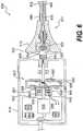
- FIG. 6Another embodiment of a rotational IVUS probe 600 having an interface module 614 and catheter 601 suitable for use with an advanced transducer technology is represented in Fig. 6 .
- the probe 600has a catheter body 602, a transducer shaft 604, and a catheter hub 616.
- the catheter body 602has a proximal end portion 606, and the transducer shaft 604 has a proximal end portion 610.
- the catheter hub 616includes a stationary exterior housing 624, a dog 626, and a connector 628.
- the connectoris represented with four conductive lines, such as 654, shown in this embodiment. It will be appreciated, however, that any suitable number of conductive lines 654 can be utilized.
- the interior of the interface module 614can include a motor 636, a motor shaft 638, a main printed circuit board (PCB) 640, a spinning element 632, and any other suitable components for the operation of the IVUS probe 600.
- the motor 636is connected to the motor shaft 638 to rotate the spinning element 632.
- the main printed circuit board 640can have any suitable number and type of electronic components 642 including but not limited to the transmitter and the receiver for the transducer.
- the spinning element 632has a complimentary connector 644 for mating with the connector 628 on the catheter hub 616.
- the connector 644can have conductive lines, such as 655, that contact the conductive lines, such as 654, on the connector 628.
- the spinning element 632is coupled to a rotary portion 648 of a rotary transformer 646.
- the rotary portion 648 of the transformer 646passes the signals to and from the stationary portion 650 of the transformer 646.
- the stationary portion 650 of the transformer 646is electrically connected to the printed circuit board 640.
- the rotary portion 648 and the stationary portion 650 of the transformer 646each have a set of windings 651, 652 to transmit a signal across the transformer 646. It will be appreciated that any suitable number of windings may be used to transmit any suitable number of signals across the transformer 646.
- the transformer 646is used to transfer AC power. Once the power has passed across from the stationary portion 650 of the transformer 646 to the rotary portion 648 of the transformer 646, it can be passed to a power supply circuit, such as a diode rectifier, on the spinning element 632 that rectifies the AC power into DC power. The rectifier can be coupled to printed circuit boards 656, 657 on the spinning element 632.
- the DC powercan be used to power the transducer as well as the other electronic components 658, 659 included on the printed circuit boards 656, 657. It will also be appreciated that a planar flex circuit may be used in place of one or more of the sets of windings as previously described.
- the probecan benefit from the utilization of certain electronic components and circuitry in order to facilitate and/or complement the operation of the transducer.
- one or more printed circuit boards 656, 657can be coupled to the spinning element 632.
- the printed circuit boards 656, 657can have any suitable number of electronic components, such as 658 and 659, coupled thereto. It will be appreciated that any suitable number of printed circuit boards 656, 657 having any suitable number and type of electronic components 658, 659 can be utilized on the spinning element 632.
- Electronic components 658, 659 on the spinning element 632allow for signal processing to take place on the spinning side of the probe 600 before the signal is communicated across the rotary/stationary boundary.
- a wireless communication mechanismis used to transmit the ultrasound signal.
- Any suitable wireless communication mechanismmay be used including, but not limited to, wireless mechanisms utilizing radio frequency or infrared.
- the wireless communication mechanismincludes transmitter and/or receiver components 682 and 684.
- the transmitter and/or receiver component 682can be attached to any suitable location such as the printed circuit board 657 on the spinning element 632.
- the transmitter and/or receiver component 684can likewise be placed in any suitable location including the main printed circuit board 640 in the interface module 614.
- signalscan be carried across the rotating and stationary mechanical components via any suitable mechanism including, but not limited to, a transformer, an optical coupler, a wireless communication mechanism, a generator, and/or brushes/contacts.
- a transformer, an optical coupler, and/or a wireless communication mechanismcan be utilized to carry signals such as an ultrasound signal.
- a transformer, a power generator, and/or brushes/contactscan be utilized to convey power to the transducer.
- the spinning elementcan have one or more printed circuit boards with a suitable number and type of active electronic components and circuitry, thus making the spinning element an active spinning element.
- electronic componentsthat can be utilized with the active spinning element include, but are not limited to, power supply circuits (such as a generator, rectifier, regulator, high voltage step-up converter, etc.), transmitters (including tripolar transmitters), time-gain-control (TGC) amplifiers, amplitude and/or phase detectors, ADC converters, optical transceivers, encoder circuits, wireless communication components, microcontrollers, and any other suitable components.
- the spinning elementcan include encoder and timing logic such that it can internally generate the transmit triggers, and thus, eliminate the need to communicate a timing signal across the spinning element. Through the embodiments described herein, excellent image quality is possible including wide bandwidth, frequency-agility, low ringdown, focused beam (including dynamically focused beam), and harmonic capability.
- a PMUT transducercan be formed by depositing a piezoelectric polymer (such as polyvinylidene fluoride - PVDF) onto a micromachined silicon substrate.
- the silicon substratecan include an amplifier and protection circuit to buffer the signal from the PVDF transducer. It can be important to include the amplifier immediately adjacent to the PVDF element because the capacitance of the electrical cables can dampen the signal from the high impedance PVDF transducer.
- the amplifiertypically requires DC power, transmit input(s), and amplifier output connections.
- the PVDF transducercan be a focused transducer to provide excellent resolution.
- having an active spinning elementpermits the utilization of an advanced transducer technology on a rotational IVUS probe.
- having an active spinning elementcan facilitate certain advanced operations of the probe.
- the enhanced bandwidth of the probe utilizing the active spinnerpermits the probe to obtain information at a plurality of different frequencies.
- the probecan be utilized to obtain ultrasound information taken at two diverse frequencies, such as 20 MHz and 40 MHz. It will be appreciated that any suitable frequency and any suitable quantity of frequencies may be used.
- lower frequency informationfacilitates a tissue versus blood classification scheme due to the strong frequency dependence of the backscatter coefficient of the blood.
- Higher frequency informationgenerally provides better resolution at the expense of poor differentiation between blood speckle and tissue, which can make it difficult to identify the lumen border.
- an algorithmcan be utilized to interleave and display the two data sets to obtain frequency-diverse information that is closely aligned in time and space. In result, a high resolution ultrasound image can be produced with clear differentiation between blood and tissue and accurate delineation of vessel borders.
- the typical 512 A-lines that compose a single frame of an imagecan be interspersed into alternating high and low frequency A-lines.
- a 20MHz imagecan show the blood as black and the tissue as gray
- the 40MHz imagecan show the blood and tissue as gray and barely, if at all, distinguishable from one another. It can be recognized through a provided algorithm that black in 20MHz and gray at 40 MHz is blood, gray at both frequencies is tissue, and black at both frequencies is clear fluid.
- the broadband capability of advanced transducer technologies, such as PMUT, facilitated by the active spinning element,can allow for closely interleaved A-lines of two or more different center frequencies, possibly including pulse-inversion A-line pairs to generate harmonic as well as fundamental information, which is then combined to provide a robust classification scheme for tissue versus blood.
- the dual frequency blood classification schemecan be further enhanced by other blood speckle reduction algorithms such as motion algorithms (such as ChromaFlo, Q-Flow, etc.), temporal algorithms, harmonic signal processing, etc. It will be appreciated that any suitable algorithm can be used.
- motion algorithmssuch as ChromaFlo, Q-Flow, etc.
- temporal algorithmssuch as ChromaFlo, Q-Flow, etc.
- harmonic signal processingetc. It will be appreciated that any suitable algorithm can be used.
- intravascular ultrasoundother types of ultrasound catheters can be made using the teachings provided herein.
- suitable types of cathetersinclude non-intravascular intraluminal ultrasound catheters, intracardiac echo catheters, laparoscopic, and interstitial catheters.
- the probemay be used in any suitable anatomy, including, but not limited to, coronary, carotid, neuro, peripheral, or venous.
Landscapes
- Health & Medical Sciences (AREA)
- Life Sciences & Earth Sciences (AREA)
- Engineering & Computer Science (AREA)
- Physics & Mathematics (AREA)
- Medical Informatics (AREA)
- Animal Behavior & Ethology (AREA)
- Radiology & Medical Imaging (AREA)
- Nuclear Medicine, Radiotherapy & Molecular Imaging (AREA)
- Biomedical Technology (AREA)
- Heart & Thoracic Surgery (AREA)
- Biophysics (AREA)
- Molecular Biology (AREA)
- Surgery (AREA)
- Pathology (AREA)
- General Health & Medical Sciences (AREA)
- Public Health (AREA)
- Veterinary Medicine (AREA)
- Gynecology & Obstetrics (AREA)
- Computer Networks & Wireless Communication (AREA)
- Acoustics & Sound (AREA)
- Multimedia (AREA)
- Computer Vision & Pattern Recognition (AREA)
- Ultra Sonic Daignosis Equipment (AREA)
Description
- Intravascular Ultrasound (IVUS) has become an important interventional diagnostic procedure for imaging atherosclerosis and other vessel diseases and defects. In the procedure, an IVUS catheter is threaded over a guidewire into a blood vessel of interest, and images are acquired of the atherosclerotic plaque and surrounding area using ultrasonic echoes. This information is much more descriptive than the traditional standard of angiography, which shows only a two-dimensional shadow of the vessel lumen. Some of the key applications of IVUS include: determining a correct diameter and length of a stent to choose for dilating an arterial stenosis, verifying that a post-stenting diameter and luminal cross-section area are adequate, verifying that a stent is well apposed against a vessel wall to minimize thrombosis and optimize drug delivery (in the case of a drug eluting stent) and identifying an exact location of side-branch vessels. In addition, new techniques such as virtual histology (RF signal-based tissue characterization) show promise of aiding identification of vulnerable plaque (i.e., plaque which is prone to rupture and lead to onset of a heart attack).
- There are two types of IVUS catheters commonly in use: mechanical/rotational IVUS catheters and solid state catheters. In a rotational IVUS catheter, a single transducer consisting of a piezoelectric crystal is rotated at approximately 1800 revolutions per minute while the element is intermittently excited with an electrical pulse. This excitation causes the element to vibrate at a frequency dependent upon the particulars of the transducer design. Depending on the dimensions and characteristics of the transducer, this operating frequency is typically in the range of 8 to 50MHz. In general terms, a higher frequency of operation provides better resolution and a smaller catheter, but at the expense of reduced depth of penetration and increased echoes from the blood (making the image more difficult to interpret). A lower frequency of operation is more suitable for IVUS imaging in larger vessels or within the chambers of the heart.
- The rotational IVUS catheter has a drive shaft disposed within the catheter body. The transducer is attached to the distal end of the drive shaft. The typical single element piezoelectric transducer requires only two electrical leads, with this pair of leads serving two separate purposes: (1) delivering the intermittent electrical transmit pulses to the transducer, and (2) delivering the received electrical echo signals from the transducer to the receiver amplifier (during the intervals between transmit pulses). The IVUS catheter is removably coupled to an interface module, which controls the rotation of the drive shaft within the catheter body and contains the transmitter and receiver circuitry for the transducer. Because the transducer is on a rotating drive shaft and the transmitter and receiver circuitry is stationary, a device must be utilized to carry the transmit pulse and received echo across a rotating interface. This can be accomplished via a rotary transformer, which comprises two halves, separated by a narrow air gap that permits electrical coupling between the primary and secondary windings of the transformer while allowing relative motion (rotation) between the two halves. The spinning element (transducer, electrical leads, and driveshaft) is attached to the spinning portion of the rotary transformer, while the stationary transmitter and receiver circuitry contained in the interface module are attached to the stationary portion of the rotary transformer.
- The other type of IVUS catheter is a solid state (or phased array) catheter. This catheter has no rotating parts, but instead includes an array of transducer elements (for example 64 elements), arrayed in a cylinder around the circumference of the catheter body. The individual elements are fired in a specific sequence under the control of several small integrated circuits mounted in the tip of the catheter, adjacent to the transducer array. The sequence of transmit pulses interspersed with receipt of the echo signals provides the ultrasound data required to reconstruct a complete cross-sectional image of the vessel, similar in nature to that provided by a rotational IVUS device.
- Currently, most IVUS systems rely on conventional piezoelectric transducers, built from piezoelectric ceramic (commonly referred to as the crystal) and covered by one or more matching layers (typically thin layers of epoxy composites or polymers). Two advanced transducer technologies that have shown promise for replacing conventional piezoelectric devices are the PMUT (Piezoelectric Micromachined Ultrasonic Transducer) and CMUT (Capacitive Micromachined Ultrasonic Transducer). PMUT and CMUT transducers may provide improved image quality over that provided by the conventional piezoelectric transducer, but these technologies have not been adopted for rotational IVUS applications due to the larger number of electrical leads they require, among other factors.
- There are many potential advantages of these advanced transducer technologies, some of which are enumerated here. Both PMUT and CMUT technologies promise reduced manufacturing costs by virtue of the fact that these transducers are built using wafer fabrication techniques to mass produce thousands of devices on a single silicon wafer. This is an important factor for a disposable medical device such as an IVUS catheter. These advanced transducer technologies provide broad bandwidth (> 100%) in many cases compared to the 30-50% bandwidth available from the typical piezoelectric transducer. This broader bandwidth translates into improved depth resolution in the IVUS image, and it may also facilitate multi-frequency operation or harmonic imaging, either of which can help to improve image quality and/or enable improved algorithms for tissue characterization, blood speckle reduction, and border detection. Advanced transducer technologies also offer the potential for improved beam characteristics, either by providing a focused transducer aperture (instead of the planar, unfocused aperture commonly used), or by implementing dynamically variable focus with an array of transducer elements (in place of the traditional single transducer element).
- Document
US20060084875A1 discloses systems and methods that allow for the application of a bias voltage to one or more transducers implemented within a medical ultrasound imaging system. Bias circuitry is placed within an imaging device and used to apply a DC bias to one or more transducers requiring a DC bias to operate. The one or more transducers can be fabricated in a semiconductor manufacturing process and integrated with the bias circuitry on a common semiconductor substrate. Also provided is a method for operating the one or more transducers and bias circuitry using a communication channel having two signal lines. - The present invention provides the enabling technology allowing advanced transducer technology to be introduced into a rotational IVUS catheter. This in turn will provide improved image quality and support advanced signal processing to facilitate more accurate diagnosis of the medical condition within the vessel. All of this can be achieved in a cost-effective way, possibly at a lower cost than the conventional technology.
- Embodiments of an intravascular ultrasound probe are disclosed herein. The probe has features for utilizing an advanced transducer technology on a rotating transducer shaft. In particular, the probe accommodates the transmission of the multitude of signals across the boundary between the rotary and stationary components of the probe required to support an advanced transducer technology. These advanced transducer technologies offer the potential for increased bandwidth, improved beam profiles, better signal to noise ratio, reduced manufacturing costs, advanced tissue characterization algorithms, and other desirable features. Furthermore, the inclusion of electronic components on the spinning side of the probe can be highly advantageous in terms of preserving maximum signal to noise ratio and signal fidelity, along with other performance benefits.
- In a disclosed embodiment, a rotational intravascular ultrasound probe for insertion into a vasculature is described as claimed in claim 1.
- In yet another disclosed embodiment, an interface module for a rotational intravascular ultrasound probe for insertion into a vasculature is described as claimed in claim 7.
Fig. 1 is a simplified fragmentary diagrammatic view of a rotational IVUS probe;Fig. 2 is a simplified fragmentary diagrammatic view of an interface module and catheter for the rotational IVUS probe ofFig. 1 incorporating basic ultrasound transducer technology;Fig. 3 is a simplified fragmentary diagrammatic view of an embodiment of an interface module and catheter for the rotational IVUS probe ofFig. 1 incorporating an advanced ultrasound transducer technology;Fig. 4 is a simplified fragmentary diagrammatic view of another embodiment of an interface module and catheter for the rotational IVUS probe ofFig. 1 incorporating an advanced ultrasound transducer technology;Fig. 5 is a simplified fragmentary diagrammatic view of another embodiment of an interface module and catheter for the rotational IVUS probe ofFig. 1 incorporating an advanced ultrasound transducer technology; andFig. 6 is a simplified fragmentary diagrammatic view of another embodiment of an interface module and catheter for the rotational IVUS probe ofFig. 1 incorporating an advanced ultrasound transducer technology.- Turning to the figures, representative illustrations of rotational intravascular ultrasound (IVUS) probes, some of which include active spinning elements, are shown therein. An active spinning element can increase the number of signal paths available for the operation of the transducer so that advanced transducer technologies, such as PMUT (Piezoelectric Micromachined Ultrasonic Transducer) and CMUT (Capacitive Micromachined Ultrasonic Transducer), can be utilized with a rotational IVUS probe. In addition, an active spinning element can include active electronics on the rotary side of the probe.
- Referring specifically to
Fig. 1 , a rotationalintravascular ultrasound probe 100 for insertion into a patient for diagnostic imaging is shown. Theprobe 100 comprises acatheter 101 having acatheter body 102 and atransducer shaft 104. Thecatheter body 102 is flexible and has both aproximal end portion 106 and adistal end portion 108. Thecatheter body 102 is a sheath surrounding thetransducer shaft 104. For explanatory purposes, thecatheter body 102 inFig. 1 is illustrated as visually transparent such that thetransducer shaft 104 disposed therein can be seen, although it will be appreciated that thecatheter body 102 may or may not be visually transparent. Thetransducer shaft 104 is flushed with a sterile fluid, such as saline, within thecatheter body 102. The fluid serves to eliminate the presence of air pockets around thetransducer shaft 104 that adversely affect image quality. The fluid can also act as a lubricant. Thetransducer shaft 104 has aproximal end portion 110 disposed within theproximal end portion 106 of thecatheter body 102 and adistal end portion 112 disposed within thedistal end portion 108 of thecatheter body 102. - The
distal end portion 108 of thecatheter body 102 and thedistal end portion 112 of thetransducer shaft 104 are inserted into a patient during the operation of theprobe 100. The usable length of the probe 100 (the portion that can be inserted into a patient) can be any suitable length and can be varied depending upon the application. Thedistal end portion 112 of thetransducer shaft 104 includes atransducer subassembly 118. - The
proximal end portion 106 of thecatheter body 102 and theproximal end portion 110 of thetransducer shaft 104 are connected to an interface module 114 (sometimes referred to as a patient interface module or PIM). Theproximal end portions catheter hub 116 that is removably connected to theinterface module 114. - The rotation of the
transducer shaft 104 within thecatheter body 102 is controlled by theinterface module 114, which provides a plurality of user interface controls that can be manipulated by a user. Theinterface module 114 also communicates with thetransducer subassembly 118 by sending and receiving electrical signals to and from thetransducer subassembly 118 via wires within thetransducer shaft 104. Theinterface module 114 can receive, analyze, and/or display information received through thetransducer shaft 104. It will be appreciated that any suitable functionality, controls, information processing and analysis, and display can be incorporated into theinterface module 114. - The
transducer shaft 104 includes atransducer subassembly 118, atransducer housing 120, and adrive cable 122. Thetransducer subassembly 118 is coupled to thetransducer housing 120. Thetransducer housing 120 is attached to thedrive cable 122 at thedistal end portion 112 of thetransducer shaft 104. Thedrive cable 122 is rotated within thecatheter body 102 via theinterface module 114 to rotate thetransducer housing 120 and thetransducer subassembly 118. Thetransducer subassembly 118 can be of any suitable type, including but not limited to one or more advanced transducer technologies such as PMUT or CMUT. Thetransducer subassembly 118 can include either a single transducer or an array. Fig. 2 shows arotational IVUS probe 200 utilizing acommon spinning element 232. Theprobe 200 has acatheter 201 with acatheter body 202 and atransducer shaft 204. As shown, thecatheter hub 216 is near theproximal end portion 206 of thecatheter body 202 and theproximal end portion 210 of thetransducer shaft 204. Thecatheter hub 216 includes astationary hub housing 224, adog 226, aconnector 228, andbearings 230. Thedog 226 mates with aspinning element 232 for alignment of thehub 216 with theinterface module 214 and torque transmission to thetransducer shaft 204. Thedog 226 rotates within thehub housing 224 utilizing thebearings 230. Theconnector 228 in this figure is coaxial. Theconnector 228 rotates with thespinning element 232, described further herein.- As shown, the interior of the
interface module 214 includes amotor 236, amotor shaft 238, a printed circuit board (PCB) 240, thespinning element 232, and any other suitable components for the operation of theIVUS probe 200. Themotor 236 is connected to themotor shaft 238 to rotate thespinning element 232. The printedcircuit board 240 can have any suitable number and type ofelectronic components 242, including but not limited to the transmitter and the receiver for the transducer. - The
spinning element 232 has acomplimentary connector 244 for mating with theconnector 228 on thecatheter hub 216. As shown, thespinning element 232 is coupled to a rotary portion 248 of arotary transformer 246. The rotary portion 248 of thetransformer 246 passes the signals to and from a stationary portion 250 of thetransformer 246. The stationary portion 250 of thetransformer 246 is wired to the transmitter and receiver circuitry on the printedcircuit board 240. - The transformer includes an insulating wire that is layered into an annular groove to form a two- or three-turn winding. Each of the rotary portion 250 and the stationary portion 248 has a set of windings, such as 251 and 252 respectively. Transformer performance can be improved through both minimizing the gap between the stationary portion 250 and the rotary portion 248 of the
transformer 246 and also by placing thewindings - Advanced transducer technologies can require more than the two conductive signal lines that a single piezoelectric transducer utilizes on a conventional rotational IVUS probe. For example, in addition to signal pathways for ultrasound information communicated with the transducer, certain advanced transducer technologies also require a power supply in order to operate. In order to pass the necessary multiple of signals between the advanced transducer technology and the interface module, a suitable structure may be needed to transmit ultrasound signals, power, and any other suitable signals across the boundary between the rotating and stationary mechanical components. Particularly for ultrasound signals, the mode of transmission must also maintain reliable signal quality, without excess noise, sufficient for the interface module to form a reliable image of the target tissue from the sensitive ultrasound signals. It will be appreciated that any suitable signals can be communicated across the boundary between the rotating and stationary mechanical components including, but not limited to, A-scan RF data, power transmit pulses, low amplitude receive signals, DC power and/or bias, AC power, and/or various control signals. The signal transfer across the boundary between the rotating and stationary mechanical components can have high frequency capability and broadband response.
- Multiple signal transfer pathways are presented herein for communicating signals across the boundary of the rotating and stationary parts. Each of these pathways are explained in further detail herein, and for purposes of discussion and explanation, certain pathways may be shown in combination with one another. It will be appreciated, however, that any of these pathways may be utilized in any suitable combination with one another to permit any suitable number of total signal pathways. Furthermore, as will be explained in further detail below, certain signal transfer pathways can be more conducive to transmitting either power or other signals, such as ultrasound signals.
- Referring to
Fig. 3 , an embodiment of arotational IVUS probe 300 having aninterface module 314 andcatheter 301 suitable for use with an advanced transducer technology is represented. As shown, theprobe 300 has acatheter body 302, atransducer shaft 304, and acatheter hub 316. Thecatheter body 302 has aproximal end 306 and thetransducer shaft 304 has aproximal end 310. Thecatheter hub 316 includes a stationaryexterior housing 324, adog 326, and aconnector 328. Theconnector 328 is represented with sixconductive lines 354 shown in this embodiment. It will be appreciated, however, that any suitable number of conductive lines can be utilized. - As shown, the interior of the
interface module 314 can include amotor 336, amotor shaft 338, a main printed circuit board (PCB) 340, aspinning element 332, and any other suitable components for the operation of theIVUS probe 300. Themotor 336 is connected to themotor shaft 338 to rotate thespinning element 332. The printedcircuit board 340 can have any suitable number and type ofelectronic components 342. - The
spinning element 332 has acomplimentary connector 344 for mating with theconnector 328 on thecatheter hub 316. Theconnector 344 can have conductive lines, such as 355, that contact the conductive lines, such as 354, on theconnector 328. As shown, thespinning element 332 is coupled to a rotary portion 348 of arotary transformer 346. The rotary portion 348 of thetransformer 346 passes the signals to and from a stationary portion 350 of thetransformer 346. The stationary portion 350 of thetransformer 346 is electrically connected to the printedcircuit board 340. - In this embodiment, the
transformer 346 has multiple sets of windings for transmitting multiple signals across thetransformer 346. Specifically, as shown, the rotary portion 348 and the stationary portion 350 of thetransformer 346 each have two sets of windings, such aswindings windings transformer 346. In this way, more signal pathways are available for aprobe 300 utilizing an advanced transducer technology. It will be appreciated that any suitable number of windings may be used to transmit any suitable number of signals across thetransformer 346. In alternative embodiments, planar flex circuits can be used in place of the windings in the transformer. The planar flex circuits can be placed very close to one another to enhance signal quality. - Another consideration for advanced transducer technologies is that the
probe 300 can benefit from the utilization of certain active electronic components and circuitry in order to facilitate and/or complement the operation of the transducer. Through active electronic components and circuitry on thespinning element 332, more complex electrical communication can take place between theinterface module 314 and the transducer. Furthermore, by handling certain signal processing functions on thespinning element 332, the number of signals that need to pass across thespinning element 332 can, in some embodiments, be reduced. - As shown, a printed
circuit board 356 can be coupled to thespinning element 332. The printedcircuit board 356 can have any suitable number ofelectronic components 358 coupled thereto. Any suitable number of printedcircuit boards 356 having any suitable number and type ofelectronic components 358 can be utilized on thespinning element 332. The electronic components on thespinning element 332 allow for signal processing to take place on the spinning side of theprobe 300 before the signal is communicated across the rotary/stationary boundary. - Typically, advanced transducer technologies require a DC power source. To provide DC power to the transducer, the
spinning element 332 can be fitted with contacts, such asslip ring contacts stationary brushes interface module 314. Each of the slip rings 360, 361 is coupled to a respective conductive line, such as 355, in theconnector 344. - In other embodiments, the transducer can be powered by an AC power source. For example, instead of using brushes and contacts, AC power can be transmitted through a set of windings in the
transformer 346. Once the power has passed across from the stationary portion 350 of thetransformer 346 to the rotary portion 348 of thetransformer 346, it can be passed to a power supply circuit, such as a diode rectifier, on thespinning element 332 that rectifies the AC power into DC power. The rectifier can be coupled to the printedcircuit board 356 on thespinning element 332 as one of theelectronic components 358. After the AC power is converted to DC power, the DC power can be used to power the transducer, as well as the otherelectronic components 358 included on printedcircuit board 356. - Turning to
Fig. 4 , an embodiment of arotational IVUS probe 400 having aninterface module 414 andcatheter 401 suitable for use with an advanced transducer technology is represented. As shown, theprobe 400 has acatheter body 402, atransducer shaft 404, and acatheter hub 416. Thecatheter body 402 has aproximal end portion 406, and thetransducer shaft 404 has aproximal end portion 410. Thecatheter hub 416 includes a stationaryexterior housing 424, adog 426, and aconnector 428. Theconnector 428 is represented with four conductive lines 454 shown in this embodiment. It will be appreciated, however, that any suitable number of conductive lines can be utilized. - As shown, the interior of the
interface module 414 can include amotor 436, amotor shaft 438, a main printed circuit board (PCB) 440, aspinning element 432, and any other suitable components for the operation of theIVUS probe 400. Themotor 436 is connected to themotor shaft 438 to rotate thespinning element 432. The printedcircuit board 440 can have any suitable number and type ofelectronic components 442. - The
spinning element 432 has acomplimentary connector 444 for mating with theconnector 428 on thecatheter hub 416. Theconnector 444 can have conductive lines, such as 455, that contact the conductive lines, such as 454, on theconnector 428. As shown, thespinning element 432 is coupled to arotary portion 448 of arotary transformer 446. Therotary portion 448 of thetransformer 446 passes the signals to and from astationary portion 450 of the transformer. Thestationary portion 450 of thetransformer 446 is electrically connected to the printedcircuit board 440. - As shown, the
rotary portion 448 and thestationary portion 450 of thetransformer 446 each have a set ofwindings transformer 446. It will be appreciated that any suitable number of windings may be used to transmit any suitable number of signals across thetransformer 446. In this embodiment, thetransformer 446 can be used to transfer the ultrasound signal. It will also be appreciated that a planar flex circuit may be used in place of one or more of the sets of windings as previously described. - The
probe 400 can benefit from the utilization of certain electronic components and circuitry in order to facilitate and/or complement the operation of the transducer. As shown, one or more printedcircuit boards spinning element 432. The printedcircuit boards circuit boards electronic components spinning element 432. Electronic components on thespinning element 432 allow for signal processing to take place on the spinning side of theprobe 400 before the signal is communicated across the rotary/stationary boundary. - According to the invention, power is provided to the transducer using a
generator mechanism 464 to generate power locally. As illustrated in the figure, thegenerator mechanism 464 includes agenerator coil 466 and a plurality ofstator magnets generator coil 466 can be attached to thespinning element 432 to rotate with thespinning element 432 and generate power. The power generated is AC power, so a power supply circuit, such as a diode rectifier, can be used to convert the AC power into DC power. The rectifier can be coupled to the printedcircuit boards spinning element 432. After rectification, the DC power can be used to power the transducer as well as the otherelectronic components circuit boards - Another embodiment of a
rotational IVUS probe 500 having aninterface module 514 andcatheter 501 suitable for use with an advanced transducer technology is represented inFig. 5 . As shown, the probe has acatheter body 502, atransducer shaft 504, and acatheter hub 516. Thecatheter body 502 has aproximal end portion 506, and thetransducer shaft 504 has aproximal end portion 510. Thecatheter hub 516 includes a stationaryexterior housing 524, adog 526, and aconnector 528. Theconnector 528 is represented with fourconductive lines 554 shown in this embodiment. It will be appreciated, however, that any suitable number of conductive lines can be utilized. - As shown, the interior of the
interface module 514 can include amotor 536, amotor shaft 538, a main printed circuit board (PCB) 540, aspinning element 532, and any other suitable components for the operation of theIVUS probe 500. Themotor 536 is connected to themotor shaft 538 to rotate thespinning element 532. The printedcircuit board 540 can have any suitable number and type ofelectronic components 542. - The
spinning element 532 has a complimentary connector 544 for mating with the connector on thecatheter hub 516. The connector 544 can have conductive lines, such as 555, that contact the conductive lines, such as 554, on theconnector 528. As shown, thespinning element 532 is coupled to arotary portion 548 of arotary transformer 546. Therotary portion 548 of thetransformer 546 passes the signals to and from thestationary portion 550 of thetransformer 546. Thestationary portion 550 of thetransformer 546 is electrically connected to the printedcircuit board 540. - As shown, the
rotary portion 548 and thestationary portion 550 of thetransformer 546 each have one set ofwindings transformer 546. It will be appreciated that any suitable number ofwindings transformer 546. In this embodiment, thetransformer 546 is used to transfer AC power. Once the power has passed across from thestationary portion 550 of thetransformer 546 to therotary portion 548 of thetransformer 546, it can be passed to a power supply circuit, such as a diode rectifier, on thespinning element 532 that rectifies the AC power into DC power. The rectifier can be coupled to the printedcircuit boards spinning element 532. After the AC power is converted to DC power, the DC power can be used to power the transducer as well as the otherelectronic components circuit boards - As previously mentioned, the
probe 500 can benefit from the utilization of certain electronic components and circuitry in order to facilitate and/or complement the operation of the transducer. As shown, one or more printedcircuit boards spinning element 532. The printedcircuit boards circuit boards electronic components spinning element 532.Electronic components spinning element 532 allow for signal processing to take place on the spinning side of theprobe 500 before the signal is communicated across the rotary/stationary boundary. - In this embodiment, an
optical coupler 570 is used to transmit the ultrasound signal. It will be appreciated that any suitable optical coupler may be used. The optical coupler can have afirst end 572 and asecond end 574. Thefirst end 572 can be stationary and receive optical signals from thesecond end 574, which can be coupled directly or indirectly to thespinning element 532. The ultrasound signal can be transmitted to circuitry on the printedcircuit board 540 or can be carried external to theinterface module 514. - One illustrative example of how the ultrasound signal could be communicated over this optical path is that the printed
circuit boards electronic components circuit boards optical coupler 570 to an optical receiver circuit included on printedcircuit board 540 or located remotely from theinterface module 514. - As shown, a structure may be provided that can provide feedback as to the angular position of the transducer. For example, an
optical device 576 may be provided that includes astationary encoder wheel 578 and anoptical detector 580. Theoptical detector 580 can be attached to a printedcircuit board 557 on thespinning element 532. - Another embodiment of a
rotational IVUS probe 600 having aninterface module 614 andcatheter 601 suitable for use with an advanced transducer technology is represented inFig. 6 . As shown, theprobe 600 has acatheter body 602, atransducer shaft 604, and acatheter hub 616. Thecatheter body 602 has aproximal end portion 606, and thetransducer shaft 604 has aproximal end portion 610. Thecatheter hub 616 includes a stationaryexterior housing 624, adog 626, and aconnector 628. The connector is represented with four conductive lines, such as 654, shown in this embodiment. It will be appreciated, however, that any suitable number ofconductive lines 654 can be utilized. - As shown, the interior of the
interface module 614 can include amotor 636, amotor shaft 638, a main printed circuit board (PCB) 640, aspinning element 632, and any other suitable components for the operation of theIVUS probe 600. Themotor 636 is connected to themotor shaft 638 to rotate thespinning element 632. The main printedcircuit board 640 can have any suitable number and type ofelectronic components 642 including but not limited to the transmitter and the receiver for the transducer. - The
spinning element 632 has acomplimentary connector 644 for mating with theconnector 628 on thecatheter hub 616. Theconnector 644 can have conductive lines, such as 655, that contact the conductive lines, such as 654, on theconnector 628. As shown, thespinning element 632 is coupled to arotary portion 648 of arotary transformer 646. Therotary portion 648 of thetransformer 646 passes the signals to and from thestationary portion 650 of thetransformer 646. Thestationary portion 650 of thetransformer 646 is electrically connected to the printedcircuit board 640. - As shown, the
rotary portion 648 and thestationary portion 650 of thetransformer 646 each have a set ofwindings transformer 646. It will be appreciated that any suitable number of windings may be used to transmit any suitable number of signals across thetransformer 646. In this embodiment, thetransformer 646 is used to transfer AC power. Once the power has passed across from thestationary portion 650 of thetransformer 646 to therotary portion 648 of thetransformer 646, it can be passed to a power supply circuit, such as a diode rectifier, on thespinning element 632 that rectifies the AC power into DC power. The rectifier can be coupled to printedcircuit boards spinning element 632. After the AC power is converted to DC power, the DC power can be used to power the transducer as well as the otherelectronic components circuit boards - As previously mentioned, the probe can benefit from the utilization of certain electronic components and circuitry in order to facilitate and/or complement the operation of the transducer. As shown, one or more printed
circuit boards spinning element 632. The printedcircuit boards circuit boards electronic components spinning element 632.Electronic components spinning element 632 allow for signal processing to take place on the spinning side of theprobe 600 before the signal is communicated across the rotary/stationary boundary. - In this embodiment, a wireless communication mechanism is used to transmit the ultrasound signal. Any suitable wireless communication mechanism may be used including, but not limited to, wireless mechanisms utilizing radio frequency or infrared. As shown, the wireless communication mechanism includes transmitter and/or
receiver components receiver component 682 can be attached to any suitable location such as the printedcircuit board 657 on thespinning element 632. The transmitter and/orreceiver component 684 can likewise be placed in any suitable location including the main printedcircuit board 640 in theinterface module 614. - Therefore, it will be appreciated that signals can be carried across the rotating and stationary mechanical components via any suitable mechanism including, but not limited to, a transformer, an optical coupler, a wireless communication mechanism, a generator, and/or brushes/contacts. In certain embodiments, a transformer, an optical coupler, and/or a wireless communication mechanism can be utilized to carry signals such as an ultrasound signal. In certain embodiments, a transformer, a power generator, and/or brushes/contacts can be utilized to convey power to the transducer.
- Furthermore, the spinning element can have one or more printed circuit boards with a suitable number and type of active electronic components and circuitry, thus making the spinning element an active spinning element. Examples of electronic components that can be utilized with the active spinning element include, but are not limited to, power supply circuits (such as a generator, rectifier, regulator, high voltage step-up converter, etc.), transmitters (including tripolar transmitters), time-gain-control (TGC) amplifiers, amplitude and/or phase detectors, ADC converters, optical transceivers, encoder circuits, wireless communication components, microcontrollers, and any other suitable components. In addition, the spinning element can include encoder and timing logic such that it can internally generate the transmit triggers, and thus, eliminate the need to communicate a timing signal across the spinning element. Through the embodiments described herein, excellent image quality is possible including wide bandwidth, frequency-agility, low ringdown, focused beam (including dynamically focused beam), and harmonic capability.
- As mentioned, any suitable advanced transducer technology may be used, including but not limited to PMUT and CMUT transducers, either as single transducers or arrays. As an example, a PMUT transducer can be formed by depositing a piezoelectric polymer (such as polyvinylidene fluoride - PVDF) onto a micromachined silicon substrate. The silicon substrate can include an amplifier and protection circuit to buffer the signal from the PVDF transducer. It can be important to include the amplifier immediately adjacent to the PVDF element because the capacitance of the electrical cables can dampen the signal from the high impedance PVDF transducer. The amplifier typically requires DC power, transmit input(s), and amplifier output connections. The PVDF transducer can be a focused transducer to provide excellent resolution.
- As mentioned above, having an active spinning element, such as is described herein, permits the utilization of an advanced transducer technology on a rotational IVUS probe. In addition, having an active spinning element can facilitate certain advanced operations of the probe. The enhanced bandwidth of the probe utilizing the active spinner permits the probe to obtain information at a plurality of different frequencies. By way of example and not limitation, the probe can be utilized to obtain ultrasound information taken at two diverse frequencies, such as 20 MHz and 40 MHz. It will be appreciated that any suitable frequency and any suitable quantity of frequencies may be used.
- Generally, lower frequency information facilitates a tissue versus blood classification scheme due to the strong frequency dependence of the backscatter coefficient of the blood. Higher frequency information generally provides better resolution at the expense of poor differentiation between blood speckle and tissue, which can make it difficult to identify the lumen border. Thus, if information is obtained at a lower frequency and a higher frequency, then an algorithm can be utilized to interleave and display the two data sets to obtain frequency-diverse information that is closely aligned in time and space. In result, a high resolution ultrasound image can be produced with clear differentiation between blood and tissue and accurate delineation of vessel borders.
- The typical 512 A-lines that compose a single frame of an image can be interspersed into alternating high and low frequency A-lines. As an example, a 20MHz image can show the blood as black and the tissue as gray, while the 40MHz image can show the blood and tissue as gray and barely, if at all, distinguishable from one another. It can be recognized through a provided algorithm that black in 20MHz and gray at 40 MHz is blood, gray at both frequencies is tissue, and black at both frequencies is clear fluid. The broadband capability of advanced transducer technologies, such as PMUT, facilitated by the active spinning element, can allow for closely interleaved A-lines of two or more different center frequencies, possibly including pulse-inversion A-line pairs to generate harmonic as well as fundamental information, which is then combined to provide a robust classification scheme for tissue versus blood.
- The dual frequency blood classification scheme can be further enhanced by other blood speckle reduction algorithms such as motion algorithms (such as ChromaFlo, Q-Flow, etc.), temporal algorithms, harmonic signal processing, etc. It will be appreciated that any suitable algorithm can be used.
- Besides intravascular ultrasound, other types of ultrasound catheters can be made using the teachings provided herein. By way of example and not limitation, other suitable types of catheters include non-intravascular intraluminal ultrasound catheters, intracardiac echo catheters, laparoscopic, and interstitial catheters. In addition, the probe may be used in any suitable anatomy, including, but not limited to, coronary, carotid, neuro, peripheral, or venous.
- Recitation of ranges of values herein are merely intended to serve as a shorthand method of referring individually to each separate value falling within the range, unless otherwise indicated herein, and each separate value is incorporated into the specification as if it were individually recited herein.
- It will be appreciated that like reference numbers and/or like shown features in the figures can represent like features. It will be appreciated that discussions of like reference numbers and/or like shown features in any embodiment may be applicable to any other embodiment.
- Illustrative embodiments of a rotational IVUS probe incorporating an advanced ultrasound transducer technology are described herein. Variations of the disclosed embodiments will be apparent to those of ordinary skill in the art in view of the foregoing illustrative examples. Those skilled in the relevant art will employ such variations as appropriate. The invention is therefore not intended to be limited to the examples described herein, but rather defined by the appended claims.
Claims (12)
- A rotational intravascular ultrasound probe (100, 200, 300, 400, 500, 600) for insertion into a vasculature, the probe comprising:an elongate catheter (101, 201, 301, 401, 501, 601) having a flexible body (102, 202, 302, 402, 502, 602), an elongate transducer shaft (104, 204, 304, 404, 504, 604) disposed within the flexible body, the transducer shaft having a drive cable (122) and a PMUT or CMUT transducer coupled to the drive cable at a distal end portion of the transducer shaft, and proximal connector (228, 328, 428, 528, 628) at or adjacent a proximal end portion of the flexible body; andan interface module (114, 214, 314, 414, 514, 614) configured to interface with the proximal connector of the elongate catheter;
characterised in that the interface module includes:a spinning element (132, 232, 332, 432, 532, 632) comprising a connector (244, 344, 444, 544, 644) configured to be fixedly coupled to the proximal connector on the proximal portion of the transducer shaft, the spinning element having an electronic component coupled thereto such that when the spinning element is fixedly coupled to the proximal portion of the transducer shaft the electronic component is in electrical contact with the transducer;a stationary element (250, 350, 450, 550, 650) positioned adjacent to and spaced from the spinning element, wherein the stationary element is configured to pass signals to the spinning element and receive signals from the spinning element; anda motor coupled (236, 336, 436, 536, 636) to the spinning element for rotating the spinning element and the transducer shaft when the spinning element is fixedly coupled to the proximal portion of the transducer shaft; andwherein the spinning element includes a generator (464) for generating power for the transducer. - The rotational intravascular ultrasound probe of claim 1, wherein the spinning element has a printed circuit board (356, 456, 457, 556, 557, 656, 657), and the electronic component is attached to the printed circuit board.
- The rotational intravascular ultrasound probe of claim 1 wherein the electronic component is selected from the group consisting of a transmitter, a time-gain-control amplifier, an amplitude detector, a phase detector, an analog to digital converter, an optical transceiver, an encoder circuit, a wireless communication component, and a microcontroller.
- The rotational intravascular ultrasound probe of claim 1 further comprising a rotary transformer (246, 346, 446, 546, 646).
- The rotational intravascular ultrasound probe of claim 1 further comprising a printed circuit board having an algorithm stored thereon for interleaving data obtained at different frequencies from the transducer.
- The rotational intravascular ultrasound probe of claim 1 further comprising at least three conductive lines (354, 355, 454, 455, 554, 555, 654, 655) electrically connecting the spinning element to the transducer.
- An interface module (114, 214, 314, 414, 514, 614) for a rotational intravascular ultrasound probe (100, 200, 300, 400, 500, 600) for insertion into a vasculature, the interface module comprising:
a connector for attachment to a proximal portion of a catheter having a transducer shaft (104, 204, 304, 404, 504, 604) with a PMUT or CMUT transducer, the connector (244, 344, 444, 544, 644) configured to fixedly engage with a complementary connector (228, 328, 428, 528, 628) on the proximal portion of the transducer shaft such that the connector is in electrical communication with the transducer;
characterised in that the interface module includes:a spinning element (132, 232, 332, 432, 532, 632) fixedly coupled to the connector, the spinning element having an electronic component coupled thereto that is in electrical contact with the connector such that when the connector is fixedly engaged with the complementary connector on the transducer shaft the electronic component is in electrical communication with the transducer;a stationary element (250, 350, 450, 550, 650) positioned adjacent to and spaced from the spinning element, wherein the stationary element is configured to pass signals to the spinning element and receive signals from the spinning element; anda motor (236, 336, 436, 536, 636) coupled to the spinning element for rotating the spinning element and the connector such that, when the connector is fixedly engaged with the complementary connector on the transducer shaft, the transducer shaft rotates with the spinning element and the connector; andwherein the spinning element includes a generator (464) for generating power for the transducer. - The interface module (114, 214, 314, 414, 514, 614) of claim 7, wherein the spinning element has a printed circuit board (356, 456, 457, 556, 557, 656, 657), and the electronic component is attached to the printed circuit board, or wherein the spinning element is attached to an optical coupler, or wherein the spinning element includes a slip ring contact for a brush.
- The interface module of claim 7 wherein the electronic component is selected from the group consisting of a transmitter, a time-gain-control amplifier, an amplitude detector a phase detector, an analog to digital converter, an optical transceiver, an encoder circuit, a wireless communication component, and a microcontroller.
- The interface module of claim 7 further comprising a rotary transformer (246, 346, 446, 546, 646).
- The interface module of claim 7 further comprising a printed circuit board having an algorithm stored thereon for interleaving data obtained at different frequencies from the transducer.
- The interface module of claim 7, wherein the connector includes at least three conductive lines (354, 355, 454, 455, 554, 555, 654, 655) electrically connected to the spinning element.
Applications Claiming Priority (2)
| Application Number | Priority Date | Filing Date | Title |
|---|---|---|---|
| US12/402,278US8403856B2 (en) | 2009-03-11 | 2009-03-11 | Rotational intravascular ultrasound probe with an active spinning element |
| PCT/US2010/026491WO2010104775A2 (en) | 2009-03-11 | 2010-03-08 | Rotational intravascular ultrasound probe with an active spinning element |
Publications (3)
| Publication Number | Publication Date |
|---|---|
| EP2405819A2 EP2405819A2 (en) | 2012-01-18 |
| EP2405819A4 EP2405819A4 (en) | 2013-03-20 |
| EP2405819B1true EP2405819B1 (en) | 2019-05-08 |
Family
ID=42729032
Family Applications (1)
| Application Number | Title | Priority Date | Filing Date |
|---|---|---|---|
| EP10751228.7AActiveEP2405819B1 (en) | 2009-03-11 | 2010-03-08 | Rotational intravascular ultrasound probe with an active spinning element |
Country Status (4)
| Country | Link |
|---|---|
| US (4) | US8403856B2 (en) |
| EP (1) | EP2405819B1 (en) |
| JP (2) | JP2012520127A (en) |
| WO (1) | WO2010104775A2 (en) |
Families Citing this family (116)
| Publication number | Priority date | Publication date | Assignee | Title |
|---|---|---|---|---|
| US9867530B2 (en) | 2006-08-14 | 2018-01-16 | Volcano Corporation | Telescopic side port catheter device with imaging system and method for accessing side branch occlusions |
| EP2178442B1 (en) | 2007-07-12 | 2017-09-06 | Volcano Corporation | Catheter for in vivo imaging |
| WO2009009802A1 (en) | 2007-07-12 | 2009-01-15 | Volcano Corporation | Oct-ivus catheter for concurrent luminal imaging |
| US9596993B2 (en) | 2007-07-12 | 2017-03-21 | Volcano Corporation | Automatic calibration systems and methods of use |
| JP5666873B2 (en)* | 2010-10-13 | 2015-02-12 | 富士フイルム株式会社 | Ultrasonic diagnostic equipment |
| US8702594B2 (en)* | 2010-10-21 | 2014-04-22 | Avram Allan Edidin | Imaging system having a quick connect coupling interface |
| US11141063B2 (en)* | 2010-12-23 | 2021-10-12 | Philips Image Guided Therapy Corporation | Integrated system architectures and methods of use |
| US11040140B2 (en) | 2010-12-31 | 2021-06-22 | Philips Image Guided Therapy Corporation | Deep vein thrombosis therapeutic methods |
| US9360630B2 (en) | 2011-08-31 | 2016-06-07 | Volcano Corporation | Optical-electrical rotary joint and methods of use |
| WO2013142425A1 (en)* | 2012-03-19 | 2013-09-26 | Volcano Corporation | Rotary transformer and associated devices, systems, and methods for rotational intravascular ultrasound |
| EP2846699A4 (en)* | 2012-05-11 | 2016-01-27 | Volcano Corp | Circuit architectures and electrical interfaces for rotational intravascular ultrasound (ivus) devices |
| CA2873391A1 (en)* | 2012-05-11 | 2013-11-14 | Volcano Corporation | Device and system for imaging and blood flow velocity measurement |
| US9717475B2 (en) | 2012-05-11 | 2017-08-01 | Volcano Corporation | Ultrasound catheter for imaging and blood flow measurement |
| US9351687B2 (en)* | 2012-06-28 | 2016-05-31 | Volcano Corporation | Intravascular devices, systems, and methods |
| US9286673B2 (en) | 2012-10-05 | 2016-03-15 | Volcano Corporation | Systems for correcting distortions in a medical image and methods of use thereof |
| US20140100454A1 (en) | 2012-10-05 | 2014-04-10 | Volcano Corporation | Methods and systems for establishing parameters for three-dimensional imaging |
| US10070827B2 (en) | 2012-10-05 | 2018-09-11 | Volcano Corporation | Automatic image playback |
| US11272845B2 (en) | 2012-10-05 | 2022-03-15 | Philips Image Guided Therapy Corporation | System and method for instant and automatic border detection |
| US9858668B2 (en) | 2012-10-05 | 2018-01-02 | Volcano Corporation | Guidewire artifact removal in images |
| US9367965B2 (en) | 2012-10-05 | 2016-06-14 | Volcano Corporation | Systems and methods for generating images of tissue |
| CA2887421A1 (en) | 2012-10-05 | 2014-04-10 | David Welford | Systems and methods for amplifying light |
| US9324141B2 (en) | 2012-10-05 | 2016-04-26 | Volcano Corporation | Removal of A-scan streaking artifact |
| US9292918B2 (en) | 2012-10-05 | 2016-03-22 | Volcano Corporation | Methods and systems for transforming luminal images |
| US10568586B2 (en) | 2012-10-05 | 2020-02-25 | Volcano Corporation | Systems for indicating parameters in an imaging data set and methods of use |
| US9307926B2 (en) | 2012-10-05 | 2016-04-12 | Volcano Corporation | Automatic stent detection |
| WO2014059315A1 (en) | 2012-10-12 | 2014-04-17 | Muffin Incorporated | Reciprocating internal ultrasound transducer assembly |
| CN104883983B (en) | 2012-10-12 | 2018-06-29 | 玛芬股份有限公司 | Mechanical scanning ultrasonic transducer with micro motor |
| US9649092B2 (en) | 2012-10-12 | 2017-05-16 | Muffin Incorporated | Devices and methods for three-dimensional internal ultrasound usage |
| JP6382202B2 (en) | 2012-10-12 | 2018-08-29 | マフィン・インコーポレイテッドMuffin Incorporated | Medical device with ultrasonic transducer |
| AU2013331627B2 (en)* | 2012-10-16 | 2018-01-18 | Muffin Incorporated | Internal transducer assembly with slip ring |
| US9840734B2 (en) | 2012-10-22 | 2017-12-12 | Raindance Technologies, Inc. | Methods for analyzing DNA |
| EP2919658B1 (en) | 2012-11-19 | 2024-03-20 | Lightlab Imaging, Inc. | Interface devices, systems and methods for multimodal probes |
| US10448922B2 (en) | 2012-12-13 | 2019-10-22 | Volcano Corporation | Rotational catheter with extended catheter body drive shaft support |
| EP2931132B1 (en) | 2012-12-13 | 2023-07-05 | Philips Image Guided Therapy Corporation | System for targeted cannulation |
| WO2014093465A1 (en)* | 2012-12-13 | 2014-06-19 | Volcano Corporation | Rotational sensing catheter with self-supporting drive shaft section |
| EP2934310A4 (en) | 2012-12-20 | 2016-10-12 | Nathaniel J Kemp | Optical coherence tomography system that is reconfigurable between different imaging modes |
| WO2014113188A2 (en)* | 2012-12-20 | 2014-07-24 | Jeremy Stigall | Locating intravascular images |
| US11406498B2 (en) | 2012-12-20 | 2022-08-09 | Philips Image Guided Therapy Corporation | Implant delivery system and implants |
| US10939826B2 (en) | 2012-12-20 | 2021-03-09 | Philips Image Guided Therapy Corporation | Aspirating and removing biological material |
| EP2934311B1 (en) | 2012-12-20 | 2020-04-15 | Volcano Corporation | Smooth transition catheters |
| US10942022B2 (en) | 2012-12-20 | 2021-03-09 | Philips Image Guided Therapy Corporation | Manual calibration of imaging system |
| CA2894716A1 (en)* | 2012-12-21 | 2014-06-26 | Lisa Fong | Rotational imaging apparatus with monolithic shaft |
| US10413317B2 (en) | 2012-12-21 | 2019-09-17 | Volcano Corporation | System and method for catheter steering and operation |
| US10332228B2 (en) | 2012-12-21 | 2019-06-25 | Volcano Corporation | System and method for graphical processing of medical data |
| JP2016502883A (en)* | 2012-12-21 | 2016-02-01 | ジョセフ ファロン, | Rotating imaging device |
| US9612105B2 (en) | 2012-12-21 | 2017-04-04 | Volcano Corporation | Polarization sensitive optical coherence tomography system |
| EP2936241B1 (en) | 2012-12-21 | 2020-10-21 | Nathaniel J. Kemp | Power-efficient optical buffering using a polarisation-maintaining active optical switch |
| JP2016501625A (en)* | 2012-12-21 | 2016-01-21 | ジェローム マイ, | Ultrasound imaging with variable line density |
| EP2934323A4 (en) | 2012-12-21 | 2016-08-17 | Andrew Hancock | SYSTEM AND METHOD FOR MULTIPLE PROCESSING OF IMAGE SIGNALS |
| US9486143B2 (en) | 2012-12-21 | 2016-11-08 | Volcano Corporation | Intravascular forward imaging device |
| CA2895769A1 (en) | 2012-12-21 | 2014-06-26 | Douglas Meyer | Rotational ultrasound imaging catheter with extended catheter body telescope |
| JP2016507892A (en) | 2012-12-21 | 2016-03-10 | デイビッド ウェルフォード, | System and method for narrowing the wavelength emission of light |
| EP2934333B1 (en)* | 2012-12-21 | 2019-05-15 | Volcano Corporation | Method for multi-frequency imaging using high-bandwidth transducer outputs |
| US10058284B2 (en) | 2012-12-21 | 2018-08-28 | Volcano Corporation | Simultaneous imaging, monitoring, and therapy |
| EP2938263B1 (en)* | 2012-12-27 | 2019-05-15 | Volcano Corporation | Fire control system for rotational ivus |
| CA2896510A1 (en)* | 2012-12-28 | 2014-07-03 | Volcano Corporation | Intravascular ultrasound catheter for minimizing image distortion |
| US20140257107A1 (en)* | 2012-12-28 | 2014-09-11 | Volcano Corporation | Transducer Assembly for an Imaging Device |
| CA2896718A1 (en) | 2012-12-28 | 2014-07-03 | Volcano Corporation | Intravascular ultrasound imaging apparatus, interface architecture, and method of manufacturing |
| US20140184023A1 (en)* | 2012-12-31 | 2014-07-03 | Volcano Corporation | Layout and Method of Singulating Miniature Ultrasonic Transducers |
| EP2938266A4 (en)* | 2012-12-31 | 2016-08-31 | Volcano Corp | Stepped banded connector for intravascular ultrasound devices |
| JP6591895B2 (en)* | 2013-01-08 | 2019-10-16 | ボルケーノ コーポレイション | Acoustic tomography method |
| US10226597B2 (en) | 2013-03-07 | 2019-03-12 | Volcano Corporation | Guidewire with centering mechanism |
| WO2014138555A1 (en) | 2013-03-07 | 2014-09-12 | Bernhard Sturm | Multimodal segmentation in intravascular images |
| EP2967391A4 (en) | 2013-03-12 | 2016-11-02 | Donna Collins | SYSTEMS AND METHODS FOR DIAGNOSING CORONARY MICROVASCULAR DISEASE |
| US20140276923A1 (en) | 2013-03-12 | 2014-09-18 | Volcano Corporation | Vibrating catheter and methods of use |
| US11026591B2 (en) | 2013-03-13 | 2021-06-08 | Philips Image Guided Therapy Corporation | Intravascular pressure sensor calibration |
| US9301687B2 (en) | 2013-03-13 | 2016-04-05 | Volcano Corporation | System and method for OCT depth calibration |
| WO2014159819A1 (en)* | 2013-03-13 | 2014-10-02 | Jinhyoung Park | System and methods for producing an image from a rotational intravascular ultrasound device |
| US10219887B2 (en) | 2013-03-14 | 2019-03-05 | Volcano Corporation | Filters with echogenic characteristics |
| US10292677B2 (en) | 2013-03-14 | 2019-05-21 | Volcano Corporation | Endoluminal filter having enhanced echogenic properties |
| US12343198B2 (en) | 2013-03-14 | 2025-07-01 | Philips Image Guided Therapy Corporation | Delivery catheter having imaging capabilities |
| US20160030151A1 (en) | 2013-03-14 | 2016-02-04 | Volcano Corporation | Filters with echogenic characteristics |
| WO2014150376A1 (en) | 2013-03-15 | 2014-09-25 | Muffin Incorporated | Internal ultrasound assembly fluid seal |
| US9502023B2 (en) | 2013-03-15 | 2016-11-22 | Fujifilm Sonosite, Inc. | Acoustic lens for micromachined ultrasound transducers |
| WO2014150373A1 (en) | 2013-03-15 | 2014-09-25 | Muffin Incorporated | Internal ultrasound assembly with port for fluid injection |
| WO2015073357A1 (en)* | 2013-11-13 | 2015-05-21 | Volcano Corporation | Visually optimized intravascular imaging and associated devices, systems, and methods |
| CN105899142B (en) | 2014-01-10 | 2020-04-10 | 火山公司 | Detecting endoleaks associated with aneurysm repair |
| KR20150090636A (en)* | 2014-01-29 | 2015-08-06 | 삼성메디슨 주식회사 | Ultrasonci probe and ultrasonic diagnostic apparatus including the same |
| US20150282784A1 (en)* | 2014-04-03 | 2015-10-08 | Analogic Corporation | Ultrasound (US) Imaging Probe With Rotating Transducer Array |
| CN103892871B (en)* | 2014-04-17 | 2015-11-25 | 深圳大学 | A kind of machinery rotating type intravascular ultrasound probes |
| EP3145414B1 (en) | 2014-05-20 | 2021-10-13 | Koninklijke Philips N.V. | Intravascular devices having drive cables with radiopaque markers |
| US20150359510A1 (en)* | 2014-06-17 | 2015-12-17 | Koninklijke Philips N.V. | Design and method for intravascular catheter |
| WO2016034977A1 (en)* | 2014-09-04 | 2016-03-10 | Koninklijke Philips N.V. | Intravascular ultrasound imaging system with slip ring interface and associated devices, systems, and methods |
| US10869592B2 (en) | 2015-02-23 | 2020-12-22 | Uroviu Corp. | Handheld surgical endoscope |
| EP3307176B1 (en) | 2015-06-12 | 2018-12-12 | Koninklijke Philips N.V. | Interconnects for intravascular ultrasound (ivus) devices |
| US20170000456A1 (en)* | 2015-07-01 | 2017-01-05 | Edan Instruments, Inc. | Apparatus and method for semi-automatic ultrasound transducer connector lock |
| WO2017027781A1 (en) | 2015-08-12 | 2017-02-16 | Muffin Incorporated | Device for three-dimensional, internal ultrasound with rotating transducer and rotating reflector |
| US11317892B2 (en) | 2015-08-12 | 2022-05-03 | Muffin Incorporated | Over-the-wire ultrasound system with torque-cable driven rotary transducer |
| EP3347735B1 (en)* | 2015-09-10 | 2021-06-02 | Koninklijke Philips N.V. | An ultrasound system with wide depth and detailed viewing |
| US10874830B2 (en) | 2015-10-05 | 2020-12-29 | Autonomix Medical, Inc. | Smart torquer and methods of using the same |
| US12295646B2 (en) | 2015-10-05 | 2025-05-13 | Autonomix Medical, Inc. | Smart torquer and methods of using the same |
| US11684248B2 (en) | 2017-09-25 | 2023-06-27 | Micronvision Corp. | Endoscopy/stereo colposcopy medical instrument |
| US11832797B2 (en) | 2016-09-25 | 2023-12-05 | Micronvision Corp. | Endoscopic fluorescence imaging |
| EP3537984B1 (en)* | 2016-11-11 | 2024-01-10 | Koninklijke Philips N.V. | A wireless intraluminal imaging device and associated devices, systems, and methods |
| US11596726B2 (en)* | 2016-12-17 | 2023-03-07 | C.R. Bard, Inc. | Ultrasound devices for removing clots from catheters and related methods |
| CN110771044A (en) | 2017-06-20 | 2020-02-07 | 蝴蝶网络有限公司 | Conversion of analog signals to digital signals in ultrasound devices |
| TW201905487A (en) | 2017-06-20 | 2019-02-01 | 美商蝴蝶網路公司 | Amplifier with built-in time gain compensation for ultrasonic applications |
| CA3064584A1 (en) | 2017-06-20 | 2018-12-27 | Butterfly Network, Inc. | Single-ended trans-impedance amplifier (tia) for ultrasound device |
| WO2018236778A1 (en)* | 2017-06-20 | 2018-12-27 | Butterfly Network, Inc. | MULTI-STAGE TRANSMITTED AMPLIFIER (TIA) FOR AN ULTRASONIC DEVICE |
| US11819360B2 (en) | 2017-08-15 | 2023-11-21 | Koninklijke Philips N.V. | Intraluminal rotational ultrasound for diagnostic imaging and therapy |
| US11980342B2 (en) | 2020-11-12 | 2024-05-14 | Micronvision Corp. | Minimally invasive endoscope |
| US12268358B2 (en) | 2019-12-05 | 2025-04-08 | Uroviu Corp. | Portable endoscope with side-mountable disposable portion |
| US11771304B1 (en) | 2020-11-12 | 2023-10-03 | Micronvision Corp. | Minimally invasive endoscope |
| EP3697314B1 (en)* | 2017-10-19 | 2021-04-21 | Koninklijke Philips N.V. | Wireless digital patient interface module using wireless charging |
| US20210196242A1 (en) | 2017-10-19 | 2021-07-01 | Koninklijke Philips N.V. | Digital rotational patient interface module |
| JP7292289B2 (en)* | 2018-02-08 | 2023-06-16 | コーニンクレッカ フィリップス エヌ ヴェ | Wireless operation for transesophageal echocardiography |
| US20210030394A1 (en)* | 2018-02-08 | 2021-02-04 | Koninklijke Philips N.V. | Devices, systems, and methods for transesophageal echocardiography |
| AU2019389001B2 (en) | 2018-11-28 | 2025-08-14 | Histosonics, Inc. | Histotripsy systems and methods |
| EP4003138A4 (en) | 2019-07-25 | 2023-08-30 | Uroviu Corp. | DISPOSABLE ENDOSCOPY NEEDLE WITH INTEGRATED GRIPPER |
| WO2021058317A1 (en) | 2019-09-23 | 2021-04-01 | Koninklijke Philips N.V. | Co-registration of intravascular and extravascular imaging for extravascular image with intravascular tissue morphology |
| CN110693530B (en)* | 2019-10-28 | 2025-07-01 | 深圳开立生物医疗科技股份有限公司 | Ultrasonic diagnostic equipment and IVUS probe connector thereof |
| US11813485B2 (en) | 2020-01-28 | 2023-11-14 | The Regents Of The University Of Michigan | Systems and methods for histotripsy immunosensitization |
| US11672590B2 (en) | 2020-07-02 | 2023-06-13 | Covidien Lp | Slip-ring contact assembly for electrosurgical instruments |
| JP2023540482A (en) | 2020-08-27 | 2023-09-25 | ザ リージェンツ オブ ザ ユニバーシティー オブ ミシガン | Ultrasonic transducer with transmitting and receiving functions for histotripsy |
| EP4608504A1 (en) | 2022-10-28 | 2025-09-03 | Histosonics, Inc. | Histotripsy systems and methods |
| US12324702B2 (en)* | 2022-11-06 | 2025-06-10 | Boston Scientific Scimed, Inc. | Ultrasonic catheter |
Citations (2)
| Publication number | Priority date | Publication date | Assignee | Title |
|---|---|---|---|---|
| US5372138A (en)* | 1988-03-21 | 1994-12-13 | Boston Scientific Corporation | Acousting imaging catheters and the like |
| US20060084875A1 (en)* | 2004-10-14 | 2006-04-20 | Scimed Life Systems, Inc. | Integrated bias circuitry for ultrasound imaging devices |
Family Cites Families (44)
| Publication number | Priority date | Publication date | Assignee | Title |
|---|---|---|---|---|
| US4803992A (en)* | 1980-10-28 | 1989-02-14 | Lemelson Jerome H | Electro-optical instruments and methods for producing same |
| US4763663A (en)* | 1983-08-11 | 1988-08-16 | Vitacomm, Ltd. | Esophageal stethoscope and vital signs monitor system |
| US4674515A (en)* | 1984-10-26 | 1987-06-23 | Olympus Optical Co., Ltd. | Ultrasonic endoscope |
| JPS61103436A (en)* | 1984-10-26 | 1986-05-21 | オリンパス光学工業株式会社 | Ultrasonic endoscope apparatus |
| JPH0653120B2 (en)* | 1985-05-10 | 1994-07-20 | オリンパス光学工業株式会社 | Ultrasonic diagnostic equipment |
| JP2758199B2 (en) | 1989-03-31 | 1998-05-28 | 株式会社東芝 | Ultrasonic probe |
| US5176140A (en) | 1989-08-14 | 1993-01-05 | Olympus Optical Co., Ltd. | Ultrasonic probe |
| US5209235A (en)* | 1991-09-13 | 1993-05-11 | Cardiovascular Imaging Systems, Inc. | Ultrasonic imaging catheter assembly and method for identification of the same |
| US5313950A (en)* | 1992-02-25 | 1994-05-24 | Fujitsu Limited | Ultrasonic probe |
| US5271402A (en) | 1992-06-02 | 1993-12-21 | Hewlett-Packard Company | Turbine drive mechanism for steering ultrasound signals |
| US5361768A (en) | 1992-06-30 | 1994-11-08 | Cardiovascular Imaging Systems, Inc. | Automated longitudinal position translator for ultrasonic imaging probes, and methods of using same |
| JP3248344B2 (en)* | 1994-04-07 | 2002-01-21 | 富士写真光機株式会社 | Insertable ultrasonic diagnostic equipment |
| US5810009A (en) | 1994-09-27 | 1998-09-22 | Kabushiki Kaisha Toshiba | Ultrasonic probe, ultrasonic probe device having the ultrasonic probe, and method of manufacturing the ultrasonic probe |
| JPH08191835A (en) | 1995-01-19 | 1996-07-30 | Toshiba Corp | Ultrasonic probe |
| US5738100A (en) | 1995-06-30 | 1998-04-14 | Terumo Kabushiki Kaisha | Ultrasonic imaging catheter |
| US5810733A (en) | 1996-05-07 | 1998-09-22 | Acuson Corporation | Encapsulated ultrasound transducer probe assembly |
| US5827313A (en)* | 1996-09-27 | 1998-10-27 | Boston Scientific Corporation | Device for controlled longitudinal movement of an operative element within a catheter sheath and method |
| US5846205A (en) | 1997-01-31 | 1998-12-08 | Acuson Corporation | Catheter-mounted, phased-array ultrasound transducer with improved imaging |
| JPH1189843A (en) | 1997-09-22 | 1999-04-06 | Fuji Photo Optical Co Ltd | Ultrasonograph to be inserted in manner of via-endoscope |
| JP3525700B2 (en) | 1997-09-24 | 2004-05-10 | 富士写真光機株式会社 | Ultrasonic probe |
| US6017312A (en)* | 1998-02-03 | 2000-01-25 | Boston Scientific Corporation | Multi-channel rotary transformer |
| US5989191A (en)* | 1998-06-19 | 1999-11-23 | Hewlettt-Packard Company | Using doppler techniques to measure non-uniform rotation of an ultrasound transducer |
| JP3635454B2 (en) | 1999-03-23 | 2005-04-06 | 日本光電工業株式会社 | Rotator for ultrasonic probe |
| US6413222B1 (en)* | 2000-04-13 | 2002-07-02 | Boston Scientific Corporation | Catheter drive shaft clutch |
| JP2001327502A (en) | 2000-05-23 | 2001-11-27 | Olympus Optical Co Ltd | Ultrasonic endoscope and ultrasonic endoscope device |
| US6709397B2 (en) | 2001-10-16 | 2004-03-23 | Envisioneering, L.L.C. | Scanning probe |
| JP2003142323A (en)* | 2001-11-01 | 2003-05-16 | Sanken Electric Co Ltd | Sheet coil and sheet transformer |
| JP2003164450A (en) | 2001-11-26 | 2003-06-10 | Ge Medical Systems Global Technology Co Llc | Ultrasonic probe |
| US7396332B2 (en) | 2002-06-10 | 2008-07-08 | Scimed Life Systems, Inc. | Transducer with multiple resonant frequencies for an imaging catheter |
| US6676606B2 (en)* | 2002-06-11 | 2004-01-13 | Koninklijke Philips Electronics N.V. | Ultrasonic diagnostic micro-vascular imaging |
| US6709396B2 (en) | 2002-07-17 | 2004-03-23 | Vermon | Ultrasound array transducer for catheter use |
| ATE465572T1 (en)* | 2004-03-22 | 2010-05-15 | Nokia Corp | SECURE DATA TRANSFER |
| US7064463B2 (en)* | 2004-07-20 | 2006-06-20 | Wavecrest Laboratories Llc | Dynamoelectric machine with embedded heat exchanger |
| TWI268149B (en) | 2004-12-29 | 2006-12-11 | Ind Tech Res Inst | Intravascular ultrasound probing device |
| US20060173350A1 (en)* | 2005-01-11 | 2006-08-03 | Scimed Life Systems, Inc. | Systems and methods for three dimensional imaging with an orientation adjustable array |
| US8257302B2 (en)* | 2005-05-10 | 2012-09-04 | Corindus, Inc. | User interface for remote control catheterization |
| US20070167821A1 (en)* | 2005-11-30 | 2007-07-19 | Warren Lee | Rotatable transducer array for volumetric ultrasound |
| US20070167825A1 (en)* | 2005-11-30 | 2007-07-19 | Warren Lee | Apparatus for catheter tips, including mechanically scanning ultrasound probe catheter tip |
| US20070178767A1 (en)* | 2006-01-30 | 2007-08-02 | Harshman E S | Electrical connector |
| US7935060B2 (en) | 2006-11-08 | 2011-05-03 | Lightlab Imaging, Inc. | Opto-acoustic imaging devices and methods |
| US8257267B2 (en)* | 2007-01-09 | 2012-09-04 | Boston Scientific Scimed, Inc. | Self-aligning IVUS catheter rotational core connector |
| CN107126182B (en)* | 2007-01-19 | 2020-06-16 | 桑尼布鲁克健康科学中心 | Scanning mechanism for imaging probe |
| US8378771B2 (en)* | 2007-12-20 | 2013-02-19 | Boston Scientific Scimed, Inc. | Rotary transformer |
| US8323203B2 (en)* | 2008-02-28 | 2012-12-04 | Boston Scientific Scimed, Inc. | Imaging catheter |
- 2009
- 2009-03-11USUS12/402,278patent/US8403856B2/enactiveActive
- 2010
- 2010-03-08JPJP2011554100Apatent/JP2012520127A/enactivePending
- 2010-03-08EPEP10751228.7Apatent/EP2405819B1/enactiveActive
- 2010-03-08WOPCT/US2010/026491patent/WO2010104775A2/enactiveApplication Filing
- 2013
- 2013-03-25USUS13/849,945patent/US8961425B2/enactiveActive
- 2015
- 2015-02-23USUS14/628,945patent/US10383596B2/enactiveActive
- 2015-12-28JPJP2015257470Apatent/JP6085664B2/enactiveActive
- 2019
- 2019-08-08USUS16/535,676patent/US11576649B2/enactiveActive
Patent Citations (2)
| Publication number | Priority date | Publication date | Assignee | Title |
|---|---|---|---|---|
| US5372138A (en)* | 1988-03-21 | 1994-12-13 | Boston Scientific Corporation | Acousting imaging catheters and the like |
| US20060084875A1 (en)* | 2004-10-14 | 2006-04-20 | Scimed Life Systems, Inc. | Integrated bias circuitry for ultrasound imaging devices |
Also Published As
| Publication number | Publication date |
|---|---|
| EP2405819A2 (en) | 2012-01-18 |
| JP6085664B2 (en) | 2017-02-22 |
| WO2010104775A3 (en) | 2011-01-13 |
| US20190357879A1 (en) | 2019-11-28 |
| US20150182188A1 (en) | 2015-07-02 |
| JP2012520127A (en) | 2012-09-06 |
| JP2016073723A (en) | 2016-05-12 |
| US11576649B2 (en) | 2023-02-14 |
| US8961425B2 (en) | 2015-02-24 |
| EP2405819A4 (en) | 2013-03-20 |
| US20100234736A1 (en) | 2010-09-16 |
| US20130218020A1 (en) | 2013-08-22 |
| US10383596B2 (en) | 2019-08-20 |
| WO2010104775A2 (en) | 2010-09-16 |
| US8403856B2 (en) | 2013-03-26 |
Similar Documents
| Publication | Publication Date | Title |
|---|---|---|
| US11576649B2 (en) | Rotational intravascular ultrasound probe with an active spinning element | |
| US12144678B2 (en) | Catheter with integrated controller for imaging and pressure sensing | |
| US20230263507A1 (en) | Wireless intraluminal imaging device and associated devices, systems, and methods | |
| US8864674B2 (en) | Circuit architectures and electrical interfaces for rotational intravascular ultrasound (IVUS) devices | |
| US20210059642A1 (en) | Intravascular ultrasound device with impedance matching structure | |
| US9022934B2 (en) | Rotary transformer and associated devices, systems, and methods for rotational intravascular ultrasound | |
| US10646200B2 (en) | Intravascular ultrasound imaging system with slip ring interface and associated devices, systems, and methods | |
| CA2319574C (en) | Multi-channel rotary transformer |
Legal Events
| Date | Code | Title | Description |
|---|---|---|---|
| PUAI | Public reference made under article 153(3) epc to a published international application that has entered the european phase | Free format text:ORIGINAL CODE: 0009012 | |
| 17P | Request for examination filed | Effective date:20111004 | |
| AK | Designated contracting states | Kind code of ref document:A2 Designated state(s):AT BE BG CH CY CZ DE DK EE ES FI FR GB GR HR HU IE IS IT LI LT LU LV MC MK MT NL NO PL PT RO SE SI SK SM TR | |
| DAX | Request for extension of the european patent (deleted) | ||
| A4 | Supplementary search report drawn up and despatched | Effective date:20130218 | |
| RIC1 | Information provided on ipc code assigned before grant | Ipc:G01N 29/24 20060101ALI20130212BHEP Ipc:A61B 8/12 20060101AFI20130212BHEP | |
| 17Q | First examination report despatched | Effective date:20160929 | |
| STAA | Information on the status of an ep patent application or granted ep patent | Free format text:STATUS: EXAMINATION IS IN PROGRESS | |
| GRAP | Despatch of communication of intention to grant a patent | Free format text:ORIGINAL CODE: EPIDOSNIGR1 | |
| STAA | Information on the status of an ep patent application or granted ep patent | Free format text:STATUS: GRANT OF PATENT IS INTENDED | |
| INTG | Intention to grant announced | Effective date:20181017 | |
| RAP1 | Party data changed (applicant data changed or rights of an application transferred) | Owner name:VOLCANO CORPORATION | |
| GRAS | Grant fee paid | Free format text:ORIGINAL CODE: EPIDOSNIGR3 | |
| GRAA | (expected) grant | Free format text:ORIGINAL CODE: 0009210 | |
| STAA | Information on the status of an ep patent application or granted ep patent | Free format text:STATUS: THE PATENT HAS BEEN GRANTED | |
| AK | Designated contracting states | Kind code of ref document:B1 Designated state(s):AT BE BG CH CY CZ DE DK EE ES FI FR GB GR HR HU IE IS IT LI LT LU LV MC MK MT NL NO PL PT RO SE SI SK SM TR | |
| REG | Reference to a national code | Ref country code:GB Ref legal event code:FG4D | |
| REG | Reference to a national code | Ref country code:CH Ref legal event code:EP Ref country code:AT Ref legal event code:REF Ref document number:1128932 Country of ref document:AT Kind code of ref document:T Effective date:20190515 | |
| REG | Reference to a national code | Ref country code:DE Ref legal event code:R096 Ref document number:602010058747 Country of ref document:DE | |
| REG | Reference to a national code | Ref country code:IE Ref legal event code:FG4D | |
| REG | Reference to a national code | Ref country code:NL Ref legal event code:MP Effective date:20190508 | |
| REG | Reference to a national code | Ref country code:LT Ref legal event code:MG4D | |
| PG25 | Lapsed in a contracting state [announced via postgrant information from national office to epo] | Ref country code:NO Free format text:LAPSE BECAUSE OF FAILURE TO SUBMIT A TRANSLATION OF THE DESCRIPTION OR TO PAY THE FEE WITHIN THE PRESCRIBED TIME-LIMIT Effective date:20190808 Ref country code:ES Free format text:LAPSE BECAUSE OF FAILURE TO SUBMIT A TRANSLATION OF THE DESCRIPTION OR TO PAY THE FEE WITHIN THE PRESCRIBED TIME-LIMIT Effective date:20190508 Ref country code:LT Free format text:LAPSE BECAUSE OF FAILURE TO SUBMIT A TRANSLATION OF THE DESCRIPTION OR TO PAY THE FEE WITHIN THE PRESCRIBED TIME-LIMIT Effective date:20190508 Ref country code:SE Free format text:LAPSE BECAUSE OF FAILURE TO SUBMIT A TRANSLATION OF THE DESCRIPTION OR TO PAY THE FEE WITHIN THE PRESCRIBED TIME-LIMIT Effective date:20190508 Ref country code:NL Free format text:LAPSE BECAUSE OF FAILURE TO SUBMIT A TRANSLATION OF THE DESCRIPTION OR TO PAY THE FEE WITHIN THE PRESCRIBED TIME-LIMIT Effective date:20190508 Ref country code:HR Free format text:LAPSE BECAUSE OF FAILURE TO SUBMIT A TRANSLATION OF THE DESCRIPTION OR TO PAY THE FEE WITHIN THE PRESCRIBED TIME-LIMIT Effective date:20190508 Ref country code:PT Free format text:LAPSE BECAUSE OF FAILURE TO SUBMIT A TRANSLATION OF THE DESCRIPTION OR TO PAY THE FEE WITHIN THE PRESCRIBED TIME-LIMIT Effective date:20190908 Ref country code:FI Free format text:LAPSE BECAUSE OF FAILURE TO SUBMIT A TRANSLATION OF THE DESCRIPTION OR TO PAY THE FEE WITHIN THE PRESCRIBED TIME-LIMIT Effective date:20190508 | |
| PG25 | Lapsed in a contracting state [announced via postgrant information from national office to epo] | Ref country code:LV Free format text:LAPSE BECAUSE OF FAILURE TO SUBMIT A TRANSLATION OF THE DESCRIPTION OR TO PAY THE FEE WITHIN THE PRESCRIBED TIME-LIMIT Effective date:20190508 Ref country code:GR Free format text:LAPSE BECAUSE OF FAILURE TO SUBMIT A TRANSLATION OF THE DESCRIPTION OR TO PAY THE FEE WITHIN THE PRESCRIBED TIME-LIMIT Effective date:20190809 Ref country code:BG Free format text:LAPSE BECAUSE OF FAILURE TO SUBMIT A TRANSLATION OF THE DESCRIPTION OR TO PAY THE FEE WITHIN THE PRESCRIBED TIME-LIMIT Effective date:20190808 | |
| REG | Reference to a national code | Ref country code:AT Ref legal event code:MK05 Ref document number:1128932 Country of ref document:AT Kind code of ref document:T Effective date:20190508 | |
| PG25 | Lapsed in a contracting state [announced via postgrant information from national office to epo] | Ref country code:CZ Free format text:LAPSE BECAUSE OF FAILURE TO SUBMIT A TRANSLATION OF THE DESCRIPTION OR TO PAY THE FEE WITHIN THE PRESCRIBED TIME-LIMIT Effective date:20190508 Ref country code:RO Free format text:LAPSE BECAUSE OF FAILURE TO SUBMIT A TRANSLATION OF THE DESCRIPTION OR TO PAY THE FEE WITHIN THE PRESCRIBED TIME-LIMIT Effective date:20190508 Ref country code:SK Free format text:LAPSE BECAUSE OF FAILURE TO SUBMIT A TRANSLATION OF THE DESCRIPTION OR TO PAY THE FEE WITHIN THE PRESCRIBED TIME-LIMIT Effective date:20190508 Ref country code:DK Free format text:LAPSE BECAUSE OF FAILURE TO SUBMIT A TRANSLATION OF THE DESCRIPTION OR TO PAY THE FEE WITHIN THE PRESCRIBED TIME-LIMIT Effective date:20190508 Ref country code:EE Free format text:LAPSE BECAUSE OF FAILURE TO SUBMIT A TRANSLATION OF THE DESCRIPTION OR TO PAY THE FEE WITHIN THE PRESCRIBED TIME-LIMIT Effective date:20190508 Ref country code:AT Free format text:LAPSE BECAUSE OF FAILURE TO SUBMIT A TRANSLATION OF THE DESCRIPTION OR TO PAY THE FEE WITHIN THE PRESCRIBED TIME-LIMIT Effective date:20190508 | |
| REG | Reference to a national code | Ref country code:DE Ref legal event code:R097 Ref document number:602010058747 Country of ref document:DE | |
| PG25 | Lapsed in a contracting state [announced via postgrant information from national office to epo] | Ref country code:IT Free format text:LAPSE BECAUSE OF FAILURE TO SUBMIT A TRANSLATION OF THE DESCRIPTION OR TO PAY THE FEE WITHIN THE PRESCRIBED TIME-LIMIT Effective date:20190508 Ref country code:SM Free format text:LAPSE BECAUSE OF FAILURE TO SUBMIT A TRANSLATION OF THE DESCRIPTION OR TO PAY THE FEE WITHIN THE PRESCRIBED TIME-LIMIT Effective date:20190508 | |
| PLBE | No opposition filed within time limit | Free format text:ORIGINAL CODE: 0009261 | |
| STAA | Information on the status of an ep patent application or granted ep patent | Free format text:STATUS: NO OPPOSITION FILED WITHIN TIME LIMIT | |
| PG25 | Lapsed in a contracting state [announced via postgrant information from national office to epo] | Ref country code:TR Free format text:LAPSE BECAUSE OF FAILURE TO SUBMIT A TRANSLATION OF THE DESCRIPTION OR TO PAY THE FEE WITHIN THE PRESCRIBED TIME-LIMIT Effective date:20190508 | |
| 26N | No opposition filed | Effective date:20200211 | |
| PG25 | Lapsed in a contracting state [announced via postgrant information from national office to epo] | Ref country code:PL Free format text:LAPSE BECAUSE OF FAILURE TO SUBMIT A TRANSLATION OF THE DESCRIPTION OR TO PAY THE FEE WITHIN THE PRESCRIBED TIME-LIMIT Effective date:20190508 | |
| PG25 | Lapsed in a contracting state [announced via postgrant information from national office to epo] | Ref country code:SI Free format text:LAPSE BECAUSE OF FAILURE TO SUBMIT A TRANSLATION OF THE DESCRIPTION OR TO PAY THE FEE WITHIN THE PRESCRIBED TIME-LIMIT Effective date:20190508 | |
| PG25 | Lapsed in a contracting state [announced via postgrant information from national office to epo] | Ref country code:MC Free format text:LAPSE BECAUSE OF FAILURE TO SUBMIT A TRANSLATION OF THE DESCRIPTION OR TO PAY THE FEE WITHIN THE PRESCRIBED TIME-LIMIT Effective date:20190508 | |
| REG | Reference to a national code | Ref country code:CH Ref legal event code:PL | |
| REG | Reference to a national code | Ref country code:BE Ref legal event code:MM Effective date:20200331 | |
| PG25 | Lapsed in a contracting state [announced via postgrant information from national office to epo] | Ref country code:LU Free format text:LAPSE BECAUSE OF NON-PAYMENT OF DUE FEES Effective date:20200308 | |
| PG25 | Lapsed in a contracting state [announced via postgrant information from national office to epo] | Ref country code:FR Free format text:LAPSE BECAUSE OF NON-PAYMENT OF DUE FEES Effective date:20200331 Ref country code:IE Free format text:LAPSE BECAUSE OF NON-PAYMENT OF DUE FEES Effective date:20200308 Ref country code:LI Free format text:LAPSE BECAUSE OF NON-PAYMENT OF DUE FEES Effective date:20200331 Ref country code:CH Free format text:LAPSE BECAUSE OF NON-PAYMENT OF DUE FEES Effective date:20200331 | |
| PG25 | Lapsed in a contracting state [announced via postgrant information from national office to epo] | Ref country code:BE Free format text:LAPSE BECAUSE OF NON-PAYMENT OF DUE FEES Effective date:20200331 | |
| PG25 | Lapsed in a contracting state [announced via postgrant information from national office to epo] | Ref country code:MT Free format text:LAPSE BECAUSE OF FAILURE TO SUBMIT A TRANSLATION OF THE DESCRIPTION OR TO PAY THE FEE WITHIN THE PRESCRIBED TIME-LIMIT Effective date:20190508 Ref country code:CY Free format text:LAPSE BECAUSE OF FAILURE TO SUBMIT A TRANSLATION OF THE DESCRIPTION OR TO PAY THE FEE WITHIN THE PRESCRIBED TIME-LIMIT Effective date:20190508 | |
| PG25 | Lapsed in a contracting state [announced via postgrant information from national office to epo] | Ref country code:MK Free format text:LAPSE BECAUSE OF FAILURE TO SUBMIT A TRANSLATION OF THE DESCRIPTION OR TO PAY THE FEE WITHIN THE PRESCRIBED TIME-LIMIT Effective date:20190508 Ref country code:IS Free format text:LAPSE BECAUSE OF FAILURE TO SUBMIT A TRANSLATION OF THE DESCRIPTION OR TO PAY THE FEE WITHIN THE PRESCRIBED TIME-LIMIT Effective date:20190908 | |
| REG | Reference to a national code | Ref country code:DE Ref legal event code:R081 Ref document number:602010058747 Country of ref document:DE Owner name:PHILIPS IMAGE GUIDED THERAPY CORP., SAN DIEGO, US Free format text:FORMER OWNER: VOLCANO CORP., SAN DIEGO, CALIF., US | |
| PGFP | Annual fee paid to national office [announced via postgrant information from national office to epo] | Ref country code:GB Payment date:20240319 Year of fee payment:15 | |
| PGFP | Annual fee paid to national office [announced via postgrant information from national office to epo] | Ref country code:DE Payment date:20250327 Year of fee payment:16 |