EP2405817B1 - System for image guided navigation - Google Patents
System for image guided navigationDownload PDFInfo
- Publication number
- EP2405817B1 EP2405817B1EP10726679.3AEP10726679AEP2405817B1EP 2405817 B1EP2405817 B1EP 2405817B1EP 10726679 AEP10726679 AEP 10726679AEP 2405817 B1EP2405817 B1EP 2405817B1
- Authority
- EP
- European Patent Office
- Prior art keywords
- tracking
- tracking device
- operable
- navigation
- patient
- Prior art date
- Legal status (The legal status is an assumption and is not a legal conclusion. Google has not performed a legal analysis and makes no representation as to the accuracy of the status listed.)
- Active
Links
Images


Classifications
- A—HUMAN NECESSITIES
- A61—MEDICAL OR VETERINARY SCIENCE; HYGIENE
- A61B—DIAGNOSIS; SURGERY; IDENTIFICATION
- A61B5/00—Measuring for diagnostic purposes; Identification of persons
- A61B5/06—Devices, other than using radiation, for detecting or locating foreign bodies ; Determining position of diagnostic devices within or on the body of the patient
- A—HUMAN NECESSITIES
- A61—MEDICAL OR VETERINARY SCIENCE; HYGIENE
- A61B—DIAGNOSIS; SURGERY; IDENTIFICATION
- A61B34/00—Computer-aided surgery; Manipulators or robots specially adapted for use in surgery
- A61B34/20—Surgical navigation systems; Devices for tracking or guiding surgical instruments, e.g. for frameless stereotaxis
- A—HUMAN NECESSITIES
- A61—MEDICAL OR VETERINARY SCIENCE; HYGIENE
- A61B—DIAGNOSIS; SURGERY; IDENTIFICATION
- A61B5/00—Measuring for diagnostic purposes; Identification of persons
- A61B5/06—Devices, other than using radiation, for detecting or locating foreign bodies ; Determining position of diagnostic devices within or on the body of the patient
- A61B5/061—Determining position of a probe within the body employing means separate from the probe, e.g. sensing internal probe position employing impedance electrodes on the surface of the body
- A61B5/064—Determining position of a probe within the body employing means separate from the probe, e.g. sensing internal probe position employing impedance electrodes on the surface of the body using markers
- A—HUMAN NECESSITIES
- A61—MEDICAL OR VETERINARY SCIENCE; HYGIENE
- A61B—DIAGNOSIS; SURGERY; IDENTIFICATION
- A61B5/00—Measuring for diagnostic purposes; Identification of persons
- A61B5/103—Measuring devices for testing the shape, pattern, colour, size or movement of the body or parts thereof, for diagnostic purposes
- A61B5/11—Measuring movement of the entire body or parts thereof, e.g. head or hand tremor or mobility of a limb
- A61B5/1126—Measuring movement of the entire body or parts thereof, e.g. head or hand tremor or mobility of a limb using a particular sensing technique
- A61B5/1127—Measuring movement of the entire body or parts thereof, e.g. head or hand tremor or mobility of a limb using a particular sensing technique using markers
- A—HUMAN NECESSITIES
- A61—MEDICAL OR VETERINARY SCIENCE; HYGIENE
- A61B—DIAGNOSIS; SURGERY; IDENTIFICATION
- A61B6/00—Apparatus or devices for radiation diagnosis; Apparatus or devices for radiation diagnosis combined with radiation therapy equipment
- A61B6/42—Arrangements for detecting radiation specially adapted for radiation diagnosis
- A61B6/4208—Arrangements for detecting radiation specially adapted for radiation diagnosis characterised by using a particular type of detector
- A61B6/4233—Arrangements for detecting radiation specially adapted for radiation diagnosis characterised by using a particular type of detector using matrix detectors
- A—HUMAN NECESSITIES
- A61—MEDICAL OR VETERINARY SCIENCE; HYGIENE
- A61B—DIAGNOSIS; SURGERY; IDENTIFICATION
- A61B6/00—Apparatus or devices for radiation diagnosis; Apparatus or devices for radiation diagnosis combined with radiation therapy equipment
- A61B6/44—Constructional features of apparatus for radiation diagnosis
- A61B6/4405—Constructional features of apparatus for radiation diagnosis the apparatus being movable or portable, e.g. handheld or mounted on a trolley
- A—HUMAN NECESSITIES
- A61—MEDICAL OR VETERINARY SCIENCE; HYGIENE
- A61B—DIAGNOSIS; SURGERY; IDENTIFICATION
- A61B6/00—Apparatus or devices for radiation diagnosis; Apparatus or devices for radiation diagnosis combined with radiation therapy equipment
- A61B6/44—Constructional features of apparatus for radiation diagnosis
- A61B6/4429—Constructional features of apparatus for radiation diagnosis related to the mounting of source units and detector units
- A61B6/4435—Constructional features of apparatus for radiation diagnosis related to the mounting of source units and detector units the source unit and the detector unit being coupled by a rigid structure
- A61B6/4441—Constructional features of apparatus for radiation diagnosis related to the mounting of source units and detector units the source unit and the detector unit being coupled by a rigid structure the rigid structure being a C-arm or U-arm
- A—HUMAN NECESSITIES
- A61—MEDICAL OR VETERINARY SCIENCE; HYGIENE
- A61B—DIAGNOSIS; SURGERY; IDENTIFICATION
- A61B6/00—Apparatus or devices for radiation diagnosis; Apparatus or devices for radiation diagnosis combined with radiation therapy equipment
- A61B6/46—Arrangements for interfacing with the operator or the patient
- A61B6/461—Displaying means of special interest
- A61B6/466—Displaying means of special interest adapted to display 3D data
- A—HUMAN NECESSITIES
- A61—MEDICAL OR VETERINARY SCIENCE; HYGIENE
- A61B—DIAGNOSIS; SURGERY; IDENTIFICATION
- A61B6/00—Apparatus or devices for radiation diagnosis; Apparatus or devices for radiation diagnosis combined with radiation therapy equipment
- A61B6/54—Control of apparatus or devices for radiation diagnosis
- A61B6/547—Control of apparatus or devices for radiation diagnosis involving tracking of position of the device or parts of the device
- A—HUMAN NECESSITIES
- A61—MEDICAL OR VETERINARY SCIENCE; HYGIENE
- A61B—DIAGNOSIS; SURGERY; IDENTIFICATION
- A61B34/00—Computer-aided surgery; Manipulators or robots specially adapted for use in surgery
- A61B34/20—Surgical navigation systems; Devices for tracking or guiding surgical instruments, e.g. for frameless stereotaxis
- A61B2034/2046—Tracking techniques
- A61B2034/2051—Electromagnetic tracking systems
- A—HUMAN NECESSITIES
- A61—MEDICAL OR VETERINARY SCIENCE; HYGIENE
- A61B—DIAGNOSIS; SURGERY; IDENTIFICATION
- A61B34/00—Computer-aided surgery; Manipulators or robots specially adapted for use in surgery
- A61B34/20—Surgical navigation systems; Devices for tracking or guiding surgical instruments, e.g. for frameless stereotaxis
- A61B2034/2046—Tracking techniques
- A61B2034/2055—Optical tracking systems
- A—HUMAN NECESSITIES
- A61—MEDICAL OR VETERINARY SCIENCE; HYGIENE
- A61B—DIAGNOSIS; SURGERY; IDENTIFICATION
- A61B90/00—Instruments, implements or accessories specially adapted for surgery or diagnosis and not covered by any of the groups A61B1/00 - A61B50/00, e.g. for luxation treatment or for protecting wound edges
- A61B90/36—Image-producing devices or illumination devices not otherwise provided for
- A61B90/37—Surgical systems with images on a monitor during operation
- A61B2090/376—Surgical systems with images on a monitor during operation using X-rays, e.g. fluoroscopy
- A61B2090/3762—Surgical systems with images on a monitor during operation using X-rays, e.g. fluoroscopy using computed tomography systems [CT]
- A—HUMAN NECESSITIES
- A61—MEDICAL OR VETERINARY SCIENCE; HYGIENE
- A61B—DIAGNOSIS; SURGERY; IDENTIFICATION
- A61B5/00—Measuring for diagnostic purposes; Identification of persons
- A61B5/06—Devices, other than using radiation, for detecting or locating foreign bodies ; Determining position of diagnostic devices within or on the body of the patient
- A61B5/061—Determining position of a probe within the body employing means separate from the probe, e.g. sensing internal probe position employing impedance electrodes on the surface of the body
- A61B5/062—Determining position of a probe within the body employing means separate from the probe, e.g. sensing internal probe position employing impedance electrodes on the surface of the body using magnetic field
- A—HUMAN NECESSITIES
- A61—MEDICAL OR VETERINARY SCIENCE; HYGIENE
- A61B—DIAGNOSIS; SURGERY; IDENTIFICATION
- A61B5/00—Measuring for diagnostic purposes; Identification of persons
- A61B5/45—For evaluating or diagnosing the musculoskeletal system or teeth
- A61B5/4504—Bones
- A—HUMAN NECESSITIES
- A61—MEDICAL OR VETERINARY SCIENCE; HYGIENE
- A61B—DIAGNOSIS; SURGERY; IDENTIFICATION
- A61B6/00—Apparatus or devices for radiation diagnosis; Apparatus or devices for radiation diagnosis combined with radiation therapy equipment
- A61B6/04—Positioning of patients; Tiltable beds or the like
- A61B6/0407—Supports, e.g. tables or beds, for the body or parts of the body
- A61B6/0421—Supports, e.g. tables or beds, for the body or parts of the body with immobilising means
Definitions
- the present disclosurerelates generally to navigated surgery, and more specifically, to a method and apparatus for performing a surgical procedure with the use of more than one surgical navigation modality.
- Image guided procedurescan utilize image data obtained prior to or during a medical procedure to assist a user, such as a surgeon, in performing and navigating a procedure. Such procedures can be referred to as navigated, guided, or computer assisted surgery procedures.
- CTcomputed tomography
- MRImagnetic resonance imaging
- fluoroscopic imagingsuch as with a C-arm device
- PETpositron emission tomography
- USultrasound
- navigation systemsmay require a dynamic reference frame to track the position of the patient should patient movement occur during the navigated procedure.
- the dynamic reference framecan be affixed to the patient.
- the dynamic reference framecan move with the patient to maintain a registration between image space and patient space.
- Document US2007/066887discloses a method and apparatus for positioning a reference frame according to the preamble of claim 1.
- An instrumentcan be tracked during an operative procedure.
- the instrumentcan be illustrated as an icon or representation superimposed on acquired image data to identify the position of the instrument relative to patient space.
- the instrumentmay include a tracking device.
- the tracking devicecan include a trackable portion, such as an electromagnetic coil or an optical detection member, which may be detected by a suitable tracking system.
- the tracking devicemay consist entirely of the trackable portion or may include a mount or fixture for the trackable portion.
- the tracking devicecan also include more than one tracking device all associated with each other and connected to a separate member.
- a dynamic reference frame (DRF)can be used by the tracking system to maintain a registration or localization of the patient space to the image space.
- the DRFcan also include any appropriate tracking device that is fixed to a portion of the patient that allows the tracking system to determine whether the patient has moved and to where. Tracking patient movement can allow registration to image space to be maintained.
- the tracking systemcan also track the imaging device that acquires the image data. In so doing, registration of the image space to patient space can occur without user intervention.
- the tracking systemcan determine both the position of the patient and the position of the imaging device during image data acquisition.
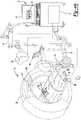
- FIG. 1is a diagram illustrating an overview of a navigation system 10 that can be used for various procedures.
- the navigation system 10can be used to track the location of an implant, such as a spinal implant or orthopedic implant, relative to a patient 14. Also, the navigation system 10 can track the position and orientation of an instrument 90, such as a biopsy needle or resection instrument. It should further be noted that the navigation system 10 may be used to navigate any type of instrument, implant, or delivery system, including: guide wires, arthroscopic systems, orthopedic implants, spinal implants, deep brain stimulation (DBS) probes, etc. Moreover, the instruments may be used to navigate or map any region of the body. The navigation system 10 and the various instruments may be used in any appropriate procedure, such as one that is generally minimally invasive or an open procedure.
- an implantsuch as a spinal implant or orthopedic implant
- an instrument 90such as a biopsy needle or resection instrument.
- the navigation system 10may be used to navigate any type of instrument, implant, or delivery system, including: guide wires, arthroscopic
- the navigation system 10includes an imaging device 12 that is used to acquire pre-, intra-, or post-operative or real-time image data of a subject, such as a patient 14. It will be understood, however, that any appropriate subject can be imaged and any appropriate procedure may be performed relative to the subject.
- the imaging device 12comprises an O-arm® imaging device sold by Medtronic Navigation, Inc. having a place of business in Louisville, Colorado, USA.
- the imaging device 12may have a generally annular gantry housing 20 and an image capturing portion 22.
- the image capturing portion 22may include an x-ray source or emission portion 26 and an x-ray receiving or image receiving portion 28 located generally or as practically possible 180 degrees from each other and mounted on a rotor (not illustrated) relative to a track or rail 29.
- the image capturing portion 22can be operable to rotate 360 degrees during image acquisition.
- the image capturing portion 22may rotate around a central point or axis, allowing image data of the patient 14 to be acquired from multiple directions or in multiple planes.
- the imaging device 12can include those disclosed in U.S. Pat. Nos. 7,188,998 ; 7,108,421 ; 7,106,825 ; 7,001,045 ; and 6,940,941 .
- the imaging device 12can utilize flat plate technology having a 1,720 by 1,024 pixel viewing area.
- the position of the image capturing portion 22can be precisely known relative to any other portion of the imaging device 12.
- the precise knowledge of the position of the image capturing portion 22can be used in conjunction with a tracking system to determine the position of the image capturing portion 22 and the image data relative to the tracked subject, such as the patient 14.
- the imaging device 12can be tracked with a tracking device 37.
- the tracking device 37can include or consist only of a trackable portion. Due to inclusion of the tracking device 37 on the imaging device 12 within the navigation system 10 and/or the determinable precise location of the image capturing portion 22 that acquires the image data of the patient 14, the image data defining an image space acquired of the patient 14 can be inherently or automatically registered relative to a patient space of the patient 14 in the navigation system 10. It will be understood, however, that image data can be acquired of any subject (e.g. a patient, a workpiece, etc.) which would define subject space. Registration allows for a translation between patient space and image space.
- the tracking device 37can include an optical tracking device.
- the optical tracking devicecan emit or reflect optical energy, such as infrared, ultraviolet, visible, etc.
- the optical energycan be received by an optical localizer 94, discussed herein, and the position of the tracking device 37 and the imaging device 12 can be determined with the navigation system 10.
- An optical tracking system, associated with the tracking device 37 and the optical localizer 94can be generally unaffected or no disturbance is introduced into the tracking system due to large metal objects.
- Other tracking systemshowever, such as an EM tracking system, can be used to track the imaging device 12. Even if the imaging device 12 may interfere or distort EM fields used with the EM tracking system, the distortions can be accounted for or shielded with the EM tracking system.
- Exemplary shielding systemsinclude those in U.S.
- the patient 14can also be tracked or fixed within the navigation system 10 to allow for registration. As discussed further herein, registration of the image space to the patient space or subject space allows for navigation of the instrument 90 with the image data. When navigating the instrument 90, a position of the instrument 90 can be illustrated relative to image data acquired of the patient 14 on a display device 74.
- Various tracking systemssuch as one including an electromagnetic (EM) localizer 84 or an optical localizer 94 can be used to track the instrument 90.
- EMelectromagnetic
- More than one tracking systemcan be used to track the instrument 90 in the navigation system 10. According to various embodiments, this can occur if both of the tracking systems, e.g., the EM localizer 84 and the optical localizer 94, include an identical frame of reference or are correlated.
- the frame of referencecan include a reference frame, such as a dynamic reference frame, connected to the patient 14. It will be understood, however, that the reference frame can be attached to any appropriate portion, such as the imaging device 12.
- the reference framecan be maintained or used to correlate the two tracking systems at a selected point, such as with one or more reference points. The use of one or more tracking systems, and specifically the use of two tracking systems within the single navigation system 10, is discussed in further detail herein.
- the imaging device 12can further include a door section 30 in the housing 20.
- the door section 30can be movable to create a lateral access or passage 31 for receiving the patient 14, as illustrated in Fig. 1A .
- the circular housing 20can be generally fixedly connected to a support housing or cart 34 associated with or including a processing unit 36.
- the imaging device 12provides an accurate and robust imaging device to capture image data of the patient 14.
- the imaging device 12includes the housing 20, rail 29, and other portions that remain substantially static, at least relative to one another.
- the cart 34can include a base 40 having a plurality of wheels 42.
- the wheels 42can be movable between a transporting position (phantom) and an operating position (solid).
- the imaging device 12provides a substantially large or stable base substantially ensures a fixed position over time, even with slight vibrations.
- the structure of the imaging device 12 as a whole and specifically the relationship between the circular housing 20 and the cart 34can provide a rigid and stable structure in the operating position. In this way, there exists substantially no flexing, bowing or other dynamic movement of the imaging device 12 relative to the patient 14 in the operating position as may exist with other imaging devices. As a result, the imaging device 12 or portions thereof may not move subsequent to image acquisition or once the location of the patient 14 is determined that may alter the determined location of the acquired image data.
- the imaging device 12can be any appropriate imaging device and can include a system to determine its position relative to a subject, such as the patient.
- Other exemplary fluoroscopesinclude bi-plane fluoroscopic systems, ceiling fluoroscopic systems, cath-lab fluoroscopic systems, fixed C-arm fluoroscopic systems, isocentric C-arm fluoroscopic systems, 3D fluoroscopic systems, etc.
- An imaging device controller 50that may control the imaging device 12 can receive the image data generated at the image capturing portion 22 and store the images for later use.
- the controller 50can also control the rotation of the image capturing portion 22 of the imaging device 12.
- the controller 50can also instruct the door 30 to move during initial positioning relative to the patient 14. It will be understood that the controller 50 need not be integral with the processing unit or processing portion 36 and may include a second and separate processor, such as that in a portable computer.
- the patient 14can be fixed onto an operating table 54.
- the table 54can be a Axis Jackson® operating table sold by OSI, a subsidiary of Mizuho Ikakogyo Co., Ltd., having a place of business in Tokyo, Japan or Mizuho Orthopedic Systems, Inc having a place of business in California, USA.
- the table 54can include a generally horizontal patient accepting portion 56 and a plurality of straps 58.
- the straps 58can be secured around the patient 14 to fix the patient 14 relative to the table 54.
- Various apparatusesmay be used to position the patient 14 in a static position on the operating table 54. Examples of such patient positioning devices are set forth in commonly assigned U.S. Pat. App. No. 10/405,068 entitled "An Integrated Electromagnetic Navigation And Patient Positioning Device", filed April 1, 2003. Other known apparatuses may include a Mayfield® clamp.
- the table 54can include a stand 62 having a lower platform 64 and a vertical support 66.
- the vertical support 66can be disposed between the patient accepting portion 56 and the lower platform 64.
- the lower platform 64can include a plurality of wheels 70.
- the wheels 70can be movable between a transporting position phantom and an operating position solid.
- the lower platform 64may also include a plurality of feet 71.
- the feet 71may be formed of resilient material suitable to securely engage and resist movement relative to the floor 44 when the wheels 70 are in the operating position.
- the wheels 70can be moved to the operating position. In the operating position, the feet 71 can engage the floor 44 and render the table 54 static with respect to the floor 44. It is appreciated that the feet 71 can be configured differently or be eliminated entirely. Further, other arrangements may be provided for locating the table 54 in a static position. Because the straps 58 can secure the patient 14 in a static position relative to the patient receiving portion 56, and the table 54 can be fixed relative to the floor 44, the patient 14 can be fixed relative to the floor 44.
- the table 54can be integral with the imaging device 12 and hence at a known location relative to the imaging device 12 or fixed at a known location relative to the imaging device 12.
- the position of the patient 14 relative to the imaging devicecan be determined by the navigation system 10.
- the tracking device 37can be used to track and locate at least a portion of the imaging device 12, for example the housing 20.
- the patient 14can be tracked with a tracking device, such as one used as a dynamic reference frame, as discussed further herein. Accordingly, the position of the patient 14 relative to the imaging device 12 can be determined. Further, the location of the imaging portion 22 can be determined relative to the housing 20 due to its precise position on the rail 29 within the housing 20, substantially inflexible rotor, etc.
- the imaging device 12can include an accuracy of within about 10 microns, for example, if the imaging device 12 is an O-Arm® imaging device sold by Medtronic Navigation, Inc. having a place of business in Louisville, Colorado.
- the O-arm® or appropriate imaging devicecan know its position and be repositioned to the same position within about 10 microns. This allows for a substantially precise placement of the imaging device and precise determination of the position of the imaging device 12. Precise positioning of the imaging portion 22 is further described in U.S. Patent Nos. 7,188,998 ; 7,108,421 ; 7,106,825 ; 7,001,045 ; and 6,940,941
- the imaging device 12generates and/or emits x-rays from the x-ray source 26 that propagate through the patient 14 and are received by the x-ray imaging receiving portion 28.
- the image capturing portion 22generates image data representing the intensities of the received x-rays.
- the image capturing portion 22can include an image intensifier that first converts the x-rays to visible light and a camera (e.g. a charge couple device) that converts the visible light into digital image data.
- the image capturing portion 22may also be a digital device that converts x-rays directly to digital image data for forming images, thus potentially avoiding distortion introduced by first converting to visible light.
- Two dimensional and/or three dimensional fluoroscopic image data that may be taken by the imaging device 12can be captured and stored in the imaging device controller 50.
- Multiple image data taken by the imaging device 12may also be captured and assembled to provide a larger view or image of a whole region of a patient 14, as opposed to being directed to only a portion of a region of the patient 14.
- multiple image data of the patient's 14 spinemay be appended together to provide a full view or complete set of image data of the spine.
- the image datacan then be forwarded from the image device controller 50 to a navigation computer and/or processor 72 that can be a part of a controller or work station 73 having the display 74 and a user interface 76. It will also be understood that the image data is not necessarily first retained in the controller 50, but may also be directly transmitted to the work station 73.
- the work station 73can provide facilities for displaying the image data as an image 77 on the display 74, saving, digitally manipulating, or printing a hard copy image of the received image data.
- the user interface 76which may be a keyboard, mouse, touch pen, touch screen or other suitable device, allows a user 81 to provide inputs to control the imaging device 12, via the image device controller 50, or adjust the display settings of the display 74.
- the work station 73may also direct the image device controller 50 to adjust the image capturing portion 22 of the imaging device 12 to obtain various two-dimensional images along different planes in order to generate representative two-dimensional and three-dimensional image data.
- radiation sensorscan sense the presence of radiation, which is forwarded to the image device controller 50, to identify whether or not the imaging device 12 is actively imaging (e.g. acquiring image data). This information can also be transmitted to a coil array controller 80, if an electromagnetic tracking system is employed, as further discussed herein.
- the navigation processor 72, tracking processor, or any appropriate portioncan identify when image data is being acquired to determine a location of the imaging device 12 at the time of imaging.
- the user 81may manually indicate when the imaging device 12 is actively imaging or this function can be built into the x-ray source 26, x-ray image receiving portion 28, or the image device controller 50.
- the navigation system 10can further include a tracking system such as an electromagnetic (EM) navigation tracking system.
- the EM tracking systemcan include the electromagnetic (EM) localizer 84, which can include a transmitter coil array.
- the EM tracking systemcan also include an EM controller 88 and the instrument 90.
- the EM controller 88can control the EM localizer 84 (such as powering the coils and controlling the coils) and interface with the instrument 90 or other tracked members or tracking devices.
- the localizer or transmitter coil array 84can be attached directly to the image device 12, attached to the OR table 54, or any other appropriate location.
- the instrument 90may be any appropriate instrument, for example, the instrument 90 may be used for preparing a portion of the patient 14, such as a biopsy needle, or positioning an implant.
- the EM tracking systemmay include the STEALTHSTATION® AXIEMTM Navigation System, sold by Medtronic Navigation, Inc. having a place of business in Louisville, Colorado; or it can be any EM tracking system described in U.S. Patent Application Serial No. 10/941,782, filed Sept. 15, 2004 , and entitled "METHOD AND APPARATUS FOR SURGICAL NAVIGATION". It will be understood that the tracking system may also be or include any appropriate tracking system, including a STEALTHSTATION® TRIA®, TREON®, and/or S7TM Navigation System having an optical localizer, similar to the optical localizer 94, sold by Medtronic Navigation, Inc. having a place of business in Louisville, Colorado. Other tracking systems include an acoustic, radiation, radar, etc. tracking or navigation systems.
- tracking systemor parts of the tracking system may be incorporated into the imaging device 12, including the work station 73, radiation sensors, localizers, 84, 94, etc. Incorporating the tracking system can provide an integrated imaging and tracking system.
- the transmitter coil array 84can include a plurality of coils and each can be generate selected electromagnetic fields in a navigation space of the subject, such as the patient 14.
- the subject space or patient spaceis the physical space occupied by or near the subject or patient.
- the navigation fieldcan at least partially overlap the subject or patient space. Discussion herein of patient space will be understood to be a specific example of subject space.
- Representative electromagnetic systemsare set forth in U.S. Patent No. 5,913,820 , entitled “Position Location System," issued June 22, 1999 and U.S. Patent No. 5,592,939 , entitled “Method and System for Navigating a Catheter Probe," issued January 14, 1997.
- the EM controller 88can drive each coil in the EM localizer 84 in a time division multiplex or a frequency division multiplex manner.
- each coilmay be driven separately at a distinct time or all of the coils may be driven simultaneously with each being driven by a different frequency.
- electromagnetic fieldscan be generated which define the navigation space.
- the electromagnetic fields generated in the patient spacecan induce currents in an EM tracking device 110 positioned on or in the instrument 90. These induced signals from the EM tracking device 110 can be transmitted to the EM controller 88 and/or the processor 72.
- the EM controller 88may provide all the necessary electrical isolation for the navigation system 10. Alternatively, the electrical isolation may also be provided in a separate device.
- the EM controller 88can also include amplifiers, filters and buffers to directly interface with the EM tracking device 110.
- the instrument 90may employ a wireless communications channel, such as that disclosed in U.S. Patent No. 6,474,341 , entitled "Surgical Communication Power System," issued November 5, 2002, as opposed to being coupled directly to EM controller 88.
- the tracking device 110can generate a field sensed by the EM localizer 84 to track the tracking device 110.
- the EM tracking device 110can consist entirely of a trackable portion, such as one or more coils.
- the tracking device 110may also include a mount or structure for holding the trackable portion in a selected location.
- the tracking device 110can include a coil (i.e. the trackable portion) and a mount to fix the trackable portion to the instrument 90.
- a tracking device according to various embodimentscan consist only of a trackable portion, such as a coil, a reflective member, or a light emitting member, and a mount to hold the trackable portion in a selected location.
- the instrument 90can be equipped with at least one, and generally multiple, of the tracking devices 110.
- the instrumentcan also include more than one type or modality of tracking device, such as the EM tracking device 110 and an optical tracking device 110'.
- the instrument 90can be a biopsy needle, handle or inserter that interconnects with an attachment and may assist in placing an implant.
- the instrument 90can include a graspable or manipulable portion at a proximal end and the tracking devices 110, 110' may be fixed near the manipulable portion of the instrument 90.
- the EM tracking device 110can be replaced by or used in conjunction with any appropriate tracking device, such as an optical tracking device 110', acoustic device, or a radar device.
- the optical tracking systemcan include that discussed above, such as the STEALTHSTATION® TREON® Tracking System sold by Medtronic Navigation, Inc.
- the optical localizer 94can include one or more cameras operable to receive an optical signal from the optical tracking device 110'.
- the optical signalcan be one actively emitted by the optical tracking device 110', such as with an L.E.D. emitter, or one reflected from reflector portions of the optical tracking device 110'.
- the emitted energycan be from a light, such as a visible or infrared light, associated or connected to the optical localizer 94.
- the field of view of the optical localizercan define the navigation space of the optical localizer 94.
- the navigation 10 systemmay be a hybrid system that includes components from various tracking systems.
- the patient space and the image spacecan be registered by identifying matching points or fiducial points in the patient space and respective points in the image space. If both of the tracking systems are registered to the image data or at least correlated to one another, either of the two tracking systems can be used to navigate a procedure.
- the imaging device 12, such as the O-arm® imaging device sold by Medtronic, Inc.can be used to generate image data at a precise and known position. This can allow image data that is automatically or inherently registered to the patient 14 upon acquisition of the image data.
- the EM localizer 84can be used to track the position of the instrument 90 including the EM tracking device 110.
- the EM tracking device 110can also be used as a DRF.
- the two tracking systems, using either the EM localizer 84 and/or the optical localizer 94,can be correlated based upon the determination or knowledge of one or more reference points in the navigation spaces of both of the tracking systems. Thus, even if only one tracking system is used to track the imaging device 12 to allow for inherent registration with that tracking system, a correlation to a second tracking system can allow the second tracking system to navigate an instrument with the image data.
- the navigation system 10can include the optical localizer 94 which can be used to track a location of the tracking device 37 associated with the imaging device 12 and an optical tracking device 120 usable as a dynamic reference frame (DRF).
- the optical tracking device 120can be interconnected with a base 122 that is further connected to the patient 14. It will be understood that the optical tracking device 120 can be used as any appropriate portion and a DRF is discussed simply as an example of an appropriate optical tracking device portion.
- the optical tracking device 120can be tracked with the optical localizer 94.
- the optical localizer 94is associated with the navigation processor 72 that is operable to determine the position of the optical tracking device 120.
- the optical localizer 94is operable to determine a position of the optical tracking device 37 associated with the imaging device 12. Also, because the patient 14 can be positioned relative to the imaging device in a selected manner, the image acquisition portion 22 allows the position of the image data acquired of the patient 14 to be known substantially precisely relative to a point on the housing 20, patient 14, cart 34, or other physical portion of the imaging device 12.
- the tracking device 37 associated with the imaging device 12enables the navigation processor 72 to substantially know the position of the imaging device 12 in the navigation space. Also, the precise knowledge or determination of an imaging portion of the imaging device can be used by the navigation processor 72 to know the position of the imaging device 12 during image acquisition.
- the navigation spaceis that space in which a localizer, such as the optical localizer 94, the electromagnetic localizer 84, or any appropriate tracking localizer, can be used to track a tracking device. It will be understood, that each localizer has a navigation space that can overlap, completely or partially, or be completely separate. As discussed herein, however, the navigation spaces can be correlated. When correlated, all points in each navigation space can be determined relative to one another.
- the optical localizer 94is able to track the tracking device 37 a position of where the image data acquired with the imaging device 12 can be substantially precisely determined in the navigation space.
- the determination of the position of the image data in the navigation spacecan be used for registration of the patient space to the image space. In other words, because the patient space and the imaging device 12 can both be moved in the navigation space the two can be automatically registered.
- Knowing or determining the position of the imaging device 12 in the navigation space when the image data is acquiredallows for substantially automatic or inherent registration of the patient space and the image space, because the patient 14 can be tracked with the tracking device 120 in the same navigation space as the imaging device 12.
- registration of image space to patient spaceallows for the generation of a translation map between the patient space and the image space.
- registrationcan occur by determining points that are substantially identical in the image space and the patient space.
- the identical pointscan include anatomical fiducial points or implanted fiducial points.
- the registration of the image space to the patient spaceis substantially automatic or inherent once the tracking device 120 is associated with the patient 14 and positioned within the navigation space.
- the tracking device 120 associated with the patient 14can be used to identify points in patient space, such as the attachment point of the tracking device 120 to the patient 14.
- a processorsuch as the one included in the navigation system, or the user can identify points in the image data identical or related to the points identified with the tracking device 120. Thus, registration can occur.
- tracking devicecan be associated with the patient during imaging.
- multiple tracking devicescan be placed at multiple locations on the patient 14. If selected, the location of each of the multiple tracking devices can be determined with the navigation system 10. This can allow multiple portions of the patient 14 to be tracked during image acquisition.
- the tracking device associated with the patient 14also need not be the optical tracking device 120.
- the tracking device used during image acquisitioncan be any appropriate tracking device, such as an EM tracking device, including the EM tracking device 130 discussed herein.
- the imaging device 12, as discussed above,can also be tracked with an EM tracking device. Accordingly, the EM localizer 84 can be used to track an EM tracking device on the patient 14 and on the imaging device 12 during image acquisition.
- the tracking device 120can include fiducial points that can be imaged with the imaging device 12.
- the tracking devicewhich is tracked with the tracking system, is at a known position to the fiducial points.
- the fiducial pointscan also be identified in the image data. Again, this allows registration.
- image data of one or more selected vertebra of the patient 14can be imaged.
- the optical tracking device 120can be interconnected with the base or connecting portion 122 of the vertebra that is imaged. Once the optical tracking device 120 is tracked or localized with the localizer 94, the image space can be substantially registered relative to the patient space by knowing the position of the imaging device 12, with the tracking device 37, and the position of the patient 14, with the optical tracking device 120. As is generally understood in the art, once the translation map is generated between the image data and the patient space any point in the patient space can be illustrated with the display device 74 and relative to the image data 77.
- the navigation system 10allows the physical position of a member, such as the instrument 90, to be illustrated relative to the image data due to registration of the image space and patient space.
- the image spacebeing the space defined by the image data and the patient or subject space being the physical space defined by and relative to the patient.
- the navigation systemincludes one or more tracking systems to track the instrument 90 and/or other physical members in the patient space.
- the tracking systemcan use alternative or multiple tracking systems.
- the electromagnetic localizer 84can also be used to track a tracking device, such as the electromagnetic (EM) tracking device 130 which can be used as a DRF.
- EMelectromagnetic
- the EM tracking device 130can be connected to the base 122 that remains connected to the patient 14.
- the optical tracking device 120can first be removed.
- both the EM tracking device 130 and the optical tracking devicecan be connected to the same base 122 for tracking the patient 14.
- a selected point relative to the base 122can be determined using both the optical tracking device 120 and the EM tracking device 130.
- a central axis of the base 122 and a point 154( FIG. 5 ) that is about 5 cm from the point of the connection of the base 122 with the patient 14 can be determined using both the optical tracking device 120 and EM tracking device 130.
- Using either of the optical tracking device 120 or the EM tracking device 130 to determine the single point 154allows for an association or correlation between the navigation space defined by the optical localizer 94 and the navigation space defined by the EM localizer 84. Once the optical and the EM tracking systems are correlated, any appropriate tracking device can be used to track the instrument 90 relative to the patient 14, regardless of the type of tracking device associated with the instrument 90.
- correlation of the two tracking systemscan be performed by identifying the single point 154 in the navigation spaces of both the EM tracking system and the optical tracking system. It will be understood, the navigation spaces of the EM and optical tracking systems can overlap or be completely separate, but the position of the single point 154 can be determined relative to the patient space and be determined in the image space to allow for correlation between the two tracking systems.
- the determination of the single point 154 in both of the navigation spacescan be done by tracking or determining a location of both the optical tracking device 120 and the EM tracking device 130. Once the single point 154 is identified in both of the navigation spaces, the remaining points in both the navigation spaces can be correlated relative to the patient space within the image data. It will be further understood, the single reference point 154 can include multiple reference points and is one or more points within a navigation space that can be identified as identical to or at a known position relative to a point in another navigation space.
- any appropriate tracking systemcan be used, such as a radar or acoustic tracking system, and the illustration of the optical tracking localizer 94 and an EM tracking localizer 84 is simply exemplary.
- both of the tracking systemscan be used substantially simultaneously for tracking one or more portions, such as the patient 14 and the instrument 90.
- the localizerscan be positioned in any appropriate location.
- the EM localizercan be associated or connected to the housing 20. Additionally, as illustrated specifically in Fig. 4B , once at least one of the tracking systems is registered to the patient space, the imaging device 12 need not be present.
- the optical localizer 94can be used to track the imaging device 12 during acquisition of the image data, once the image data is acquired with the imaging device 12, while being tracked with a selected tracking system, the imaging device 12 can be removed.
- the correlation with a second tracking systemcan occur by using a second tracking device, as discussed herein.
- the tracking systemscan be used to track any appropriate instrument relative to any appropriate system, such as tracking an instrument relative to a mechanical system (e.g. aerospace systems, automobile systems, etc.)
- more than one systemsuch as both of the optical and the EM tracking systems, can be used to track a single or multiple tracking devices substantially simultaneously.
- the tracking systemincluding the navigation processor 72, can be provided to determine and calculate the appropriate location of one or more tracking devices relative to the image data 77. Examples of appropriate navigation systems include STEALTHSTATION® AXIEMTM, or TRIA® Plus, both sold by Medtronic Navigation, Inc.
- the single base or mount 122can be connected to the patient 14 to allow for interconnection of the selected optical tracking device 120 or the EM tracking device 130 with the patient 14.
- the mount 122can be mounted to a portion or projection of a vertebra 140.
- the mount 122can include a clamp or set screw 142 that can pass through or compress a portion of the mount 122 with the vertebra 140.
- the mount 122can include a receiving portion or mounting portion 144 that engages an optical mounting portion 146 or an EM mounting portion 148.
- the receiving or mounting portion of the mount 122can calibrated position/orientation specific configuration relative to the respective mounting portions of the optical and EM trackable portions 146, 148.
- Calibrationcan include determining an orientation of the optical and EM trackable portions 146, 148 or a keyed interconnection between the mounting portion of the mount 122 and the optical and EM trackable portions 146, 148. This can allow the tracking devices 120, 130 to be positioned relative to the mount 122 in a substantially repeatable and known position.
- the optical tracking device 120can include one or more reflective or actively emitting optical portions 150 that can be sensed with the optical localizer 94. If the optical portions 150 are reflective, the optical localizer or any appropriate portion can emit an energy, such as infrared or visible light energy, to be reflected and sensed by the optical localizer 94.
- the EM tracking device 130can include an electromagnetic coil that can sense or generate an electromagnetic field. The transmission of information regarding the sensed field can be sent wirelessly or via a wire 152 to the navigation processor 72 through the navigation probe interface 88.
- a position of the reference point 154can be determined using either and/or both of the tracking systems and the tracking devices 120, 130.
- the tracking point or reference point 154can be any appropriate point relative to the mount 122 and is illustrated as within the mount 122 simply as an example.
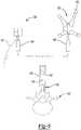
- the mount 122can be interconnected with a portion of the patient 14, such as the vertebra 140.
- the mount 122can include a compression portion or a set screw 142.
- the mount 122can include a mounting portion or a mounting receiving portion 144.
- the mounting portion 144can connect to a post 160.
- the post 160can incorporate or have mounted thereon an EM tracking device 162. If the EM tracking device 162 transmits a signal via a wire 164 it can also be interconnected with the post 160.
- the EM tracking device 162can work similarly to the EM tracking device 130 in sensing or emitting a field.
- the post 160when interconnected with the mounting bracket 122, can further connect directly with an optical tracking device 170.
- the optical tracking device 170can include an engageable region or area.
- the engageable region or areacan include a passage or depression 172 to connect with the post 160.
- a set pin or spring loaded pin 174can pass through a portion of the optical tracking device 170 to hold the optical tracking device 170 relative to the post 160.
- the two tracking devicesincluding the respective optical and EM tracking portions, can cooperate to allow tracking of a single portion with both tracking devices.
- both of the EM tracking devices 162 and the optical tracking device 170can be connected with the mount 122 substantially simultaneously.
- a single reference point 154can be determined with both of the EM tracking device 162 and the optical tracking device 170.
- the optical tracking device 170can then be easily removed from the post 160 by use of the set pin 174 at a selected time.
- the reference point 154can be tracked or located in both of the respective tracking systems.
- either of the respective tracking systems, optical or electromagneticcan both determine the position of the reference point 154 and the optical tracking device 170 can be removed from the post 160 and the EM tracking device 162 can continue to be tracked or be used as a DRF.
- the mount 122as discussed above, can be interconnected with a vertebra 140.
- a tracking device or assembly 180can be interconnected with the mount 122 by connecting with a receiving or mounting portion 144.
- the tracking assembly 180can include a tracking plate or member 182 onto which can be assembled or into which can be incorporated one or more EM tracking devices 184 and one or more optical tracking portions 186a-c.
- the EM tracking device 184can generate or sense an electromagnetic field.
- the EM tracking device 184can transmit information via a wire 188 if selected.
- the optical tracking devices 186a-186ccan emit appropriate optical energy or reflect optical energy to be tracked with a localizing device 94.
- the tracking member 182can be substantially rigid or formable in a substantially known and fixable manner.
- the tracking member 182can be provided in multiple pieces or fold along a folding or moveable joint 190, but be fixed in a selected position relative to the mount 122. When fixed, the tracking member 182 can be used with the trackable portions to determine the location with the reference point 154 relative to the mount 122.
- both of the EM tracking device 184 and the optical tracking portions 186a-186care connected to the tracking member 182, both the EM and the optical tracking systems can be used to track or determine the reference point 154 substantially simultaneously. Because both of the optical tracking portions 186a-186c and the EM tracking device 184 are fixedly positioned relative to the member 182 and to each other, determining the reference point 154 or providing a dynamic reference frame individually within both of the EM and the optical tracking systems can occur. This allows for both the optical and the EM tracking systems to be correlated to one another due to the determination of a reference point with both the tracking systems.
- the reference pointcan be a single point determined with the EM tracking device 184 and the optical tracking portions 186a-c. Again, it will be understood, that the tracking assembly 180 can be both a DRF and used to track any appropriate instrument relative to the patient 14.
- a tracking assembly 180'can be provided that is substantially similar to the tracking assembly 180 illustrated in Fig. 7 .
- the tracking assembly 180'can include one or more EM tracking devices 184' and one or more optical tracking portions 186a-c'. Again, the EM tracking device 184' can transmit information via a wire 188'.
- the tracking assembly 180'can be interconnected with an instrument such as the instrument 90, discussed above, or an instrument or pointer probe 190.
- the probe 190can be used with the tracking assembly 180' in both the EM and optical tracking systems to track any appropriate portion of the instrument 190, such as a tip 192.
- Tracking the tip 192 of the instrument or probe 190can allow for a determination of a point of the tip 192 within either of the tracking systems, including the optical or EM tracking system. This can allow for the determination of a reference point, such as the reference point 154, in both the EM and optical tracking systems.
- a reference pointsuch as the reference point 154
- the user 81can touch a point or multiple points in the patient space and also determine or identify the similar points in the image space to register the patient space to the image space.
- the registrationcan be done in both of the tracking systems, including the EM and optical tracking systems, substantially simultaneously. Accordingly, the single act of determining points or determining fiducials in the patient space can be used to correlate the two tracking systems during the registration. Because both of the fiducial or registration points are identified with both of the tracking systems, both of the tracking systems can be registered to the image space and be correlated to one another due to the identification of the same fiducial points.
- the tracking assemblies 180 or 180'can be used to identify or track an instrument substantially continuously during a procedure with either or both tracking systems. Because the tracking members 182, 182' include both the EM tracking devices 184, 184' and the optical tracking portions 186a-c, 186a-c', both of the tracking systems can be used to track the instrument to which the tracking members 182, 182' are connected.
- optical tracking portions 186a-186ccan be provided in any shape, number, or position as selected. Providing three, four, or any appropriate number of the optical tracking portions, according to various embodiments, is merely exemplary.
- an optical tracking device 200can be positioned relative to an EM tracking device 202, and both can be used to correlate both an EM and an optical tracking systems.
- the optical localizer 94 and the electromagnetic localizer 84can be used, substantially simultaneously or serially, to track or determine the position of the respective tracking devices 200, 202.
- the optical tracking device 200can be connected to any appropriate portion of an anatomy, such as a first vertebra 204.
- the EM tracking devicecan be connected to any other appropriate portion of the anatomy, such as the same vertebra 204 or a second or different vertebra 206. Between the two vertebrae 204, 206 can be an intervertebral disc 208.
- Various tissues or portions, such as fusion implantscan also be used to hold the first vertebra 204 and the second vertebra 206 at a substantially fixed position relative to one another.
- a reference point on the two vertebrae 204, 206can be determined using both of the tracking devices 200, 202. It will be understood, however, that the reference point can be positioned at any point relative to the patient 14 and in the vertebrae 204, 206 is merely exemplary. For example, however, a first reference point 210 can be determined within the first vertebra 204 and a second reference point 212 can be determined within the second vertebra 206.
- the imaging device 12can be used to acquire image data of the patient 14 and it can include image data of the first vertebra 204 and the second vertebra 206. In the image data, the position of the first vertebra 204 and the second vertebra 206 can be identified.
- the reference points 210, 212can also be identified relative to the imaged vertebrae in the image data. Accordingly, determining the position of the reference points 210, 212 with the respective tracking devices 200, 202 can be used to correlate the two tracking systems because measurements can be made using the image data to precisely determine the position of the two reference points measured or determined with the two tracking devices.
- a method of correlating at least two tracking systemsis illustrated in a flowchart 300.
- the methodcan start in start block 302.
- a tracking devicecan be attached to the imaging device in block 304. It will be understood, however, that the imaging device may inherently include or already have attached thereto a tracking device.
- the imaging device 12can be tracked in a first navigation space in block 306.
- the tracking device 37can be attached to the imaging device 12 to track the position of the imaging device 12 in the first navigation space.
- a subjectsuch as the patient 14, can also be tracked in the first navigation space in block 308.
- the tracking device 120can be attached to the patient 14 to track the patient 14 in the first navigation space, which can be defined with an optical tracking system. Therefore, both the imaging device 12 and the patient 14 can be tracked in the same navigation space defined by the first tracking system, which may include the optical localizer 94.
- Image datacan be acquired in block 310 while tracking both the imaging device in block 306 and the subject in block 308.
- the position of the image acquisition portion of the imaging devicecan be determined relative to the subject in block 312.
- the imaging device 12can include the O-Arm® Imaging System sold by Medtronic, Inc., which can allow for a substantially precise determination of a position of the image acquisition portion.
- tracking the imaging device 12 in the first navigation space and tracking the subject in the first navigation spacecan allow for a determination of a position of the image acquisition portion relative to the subject, such as the patient 14.
- determining a position of the image acquisition portion 22 relative to the gantry housing 20 of the imaging device 12can be performed.
- the tracking device 37can be attached to the gantry housing 20.
- the position of the gantry housing 20is known in the navigation space and the position of the image acquisition portion 22 is known relative to the gantry housing 20.
- the image acquisition portion 22can be known in the first navigation space.
- Determining the position of the image acquisition portioncan allow for a determination of the position of the image data in block 314. That determination can allow or determine a position of the image data relative to the subject.
- the position of the image data relative to the subjectcan be determined by fixing the subject relative to at least a portion of the imaging device or the image acquisition portion. Alternatively, or in addition thereto, determining the position of the image data can be based upon the determined position of the image acquisition portion relative to the subject in block 312.
- a registrationcan be determined in block 316.
- the registrationis between the image data defining the image space and the subject defining the subject space.
- the registrationcan be inherent or substantially automatic based upon the tracked position of the imaging device and the subject.
- identifying multiple points or fiducial points in the image data or subject spacecan be used to register the image space and the subject space.
- the registrationcan be performed substantially automatically, such as with the navigation processor 72.
- registrationcan be between the image data and one or a first tracking system.
- the subjectis tracked in the first navigation space and the imaging device can be tracking in the first navigation space.
- the image data and the subject spacecan be registered with the first navigation space.
- this registrationcan be used to correlate a second navigation space to the image space to allow a registration of the image data and the second tracking system or second navigation space.
- first and second tracking systemscan operate in substantially different manners or modalities, such as the first tracking system being an optical tracking system and the second tracking system being an electromagnetic tracking system.
- the correlationcan occur by identifying a reference point in both the first and the second navigation spaces. Determining a first reference point with a first tracking device in the first tracking system and in the first navigation space can occur in block 318. Determining a second reference point with a second tracking device and in a second navigation space can occur in block 320. Correlation of the first reference point and the second reference point can occur in block 322.
- the correlationcan include determining that the first reference point and the second reference point are the same points in subject space or can include a plurality of identical points in subject space. Alternatively, as discussed above, the correlation of the first reference point and the second reference point can be two points that are not the same point in the subject space, but can be substantially precisely located relative to one another in the subject space, such as using the registered image data.
- the first navigation space and the second navigation spacecan be correlated in block 324.
- the correlation of the first and second navigation spacescan occur by determining a translation map between the first and second navigation spaces based upon the correlated first and second reference points or any appropriate number of reference points.
- registration between the image space and the subject spacecan be determined by registering or correlating identical points in the image space and the patient space.
- Spatial calculationscan be made based upon the reference points in the first and second navigation spaces to correlate all of the points in the first and second navigation spaces.
- the first and second navigation spacescan be entirely separate, overlap partially, or overlap completely. Therefore, the first and second reference points can be at a single physical location in subject space but at different locations within the first and second navigation spaces.
- a registration with the second tracking system and the second navigation space to the image datacan occur in block 326. This can be determined because the first navigation space or the first tracking system has been registered to the image data. Once the correlation between the first and second navigation space has been made, that correlation can be used to determine a registration between the image data and the second tracking system. Accordingly, an instrument can be navigated using the second tracking system with the registered image data in block 328. A navigated procedure can then be performed in block 330, such as a spinal fusion, spinal implant, biopsy procedure, neurological procedure, orthopedic procedure, or any appropriate procedure. The method can then end in block 332.
- an imaging devicecan be used to acquire image data of a subject, such as a patient or any appropriate physical system or assembly, and more than one tracking system can be used to track an instrument relative to the subject.
- the two tracking systemscan be registered to the image data after registering a single one of the tracking systems relative to the image data based upon correlating the first and second tracking systems.
- the correlation of the first and second tracking systemscan occur by identifying reference points of the first and second navigation spaces to correlate the first and second navigation spaces of the first and second tracking system.
- the imaging system 12which can be provided as the O-arm® imaging system, sold by Medtronic, Inc. and can provide a selected image data of the patient 14.
- the image acquisition portion of the O-arm® imaging systemcan allow for a substantially precise positioning of the image acquisition portion relative to the patient 14. This can allow the position of the image acquisition portion to be precisely identified relative to the tracking device 37 without positioning the tracking device 37 on the image acquisition portion directly.
- the second tracking systemsuch as the EM tracking system including the EM localizer 84, can be used after correlating the navigation space of the EM tracking system with a navigation space of the optical tracking system as discussed above.
- processors or controllerscan mean one or more individual physical processor cores, computers, etc.
- all of the various processor portionscan be one or more computer programs executed by a single processor chip or core. The executed instructions and results can be saved in a memory system until called.
- the processorsmay include separated and distinct physical portions or may be executed by a single physical processor.
- the optical localizer 94 operating in an optical modalitymay be unaffected by large metal objects, such as the imaging device 12.
- the EM localizer 84may allow tracking of instruments without line of site to the instrument to be tracked. Accordingly, different tracking systems with different modalities can provide different advantages or properties. Also, two tracking systems, even if they are using the same modality, can be provided with different resolution, features, or spatial positions. Thus, allowing a correlation between two tracking systems, whether or not two different tracking modalities are used, can be selected.
- the position of the tracking device that is associated with the patient 14can be calibrated.
- the optical tracking device 120can be associated with the mount 122 and later the second EM tracking device 130 can be associated with the same mount 122.
- the two tracking devicescan be calibrated relative to the location of the mount or their location relative to the patient 14.
- Calibrationcan include a known specific orientation, such as with a keyed connection, of the respective tracking devices 120, 130 with the mount 122.
- the mount 122such as the receiving portion 144, can include a specific configuration, such as a flat or polygonal configuration, that mates in only a single configuration with the respective mounting portions 146, 148 of the tracking devices 120, 130.
- the tracking devices 120, 130can interact or mate with the mount 122 in only a single configuration and orientation. Accordingly, the tracked portions of both of the tracking devices 120, 130 is known relative to the mount 122.
- the location or position of either or both of the tracking devices 120, 130can be determined with a calibration measurement.
- calibration of the location of the tracking devicescan include inputting a specific location and orientation of the tracking devices 120, 130 into the navigation system 10.
- a tracked instrumentsuch as the tracked instruments 190, can be used to determine the position and/or orientation of the tracking device 120, 130 when connected or mounted in the mount 122. Accordingly, the navigation system 10 can determine the position of the tracking device 120, 130 without a requirement for predetermined position and/or orientation of the tracking device 120, 130 with the mount 122.
- Calibration of the tracking device 120, 130 with the mount 122can also include communication between the tracking device 120, 130 and the mount 122.
- a position systemcan determine an orientation of the tracking device 120, 130 with the mount 122.
- the positioning systemcan include the mounting portion 144 having contacts on a surface of the mounting portion 144.
- the mounting portions 146, 148 of the tracking devices 120, 130can include respective contacting portions to contact or complete a circuit between one or more of the contact portions within the mounting portion 144.
- the orientation of the tracking device 120, 130 relative to the mount 122can be determined. This can allow a position or orientation of the tracking device 120, 130 to be determined.
- a position of the tracking device 120, 130can be determined relative to the mounting device 122 in any appropriate manner.
- the positioncan be determined via a physical connection of the tracking device 120, 130 and the mount 122.
- the physical connectioncan include a keyed connection or position determining system.
- the position of the tracking device 120, 130can be determined with a separate selected tracking instrument. Regardless of the method to calibrate or determine the location of the respective tracking devices 120, 130, or any appropriate tracking device relative to the mount or the patient 122, 14, respectively, the position of more than one tracking device relative to the mount 122 or the patient 14 can be determined.
Landscapes
- Health & Medical Sciences (AREA)
- Life Sciences & Earth Sciences (AREA)
- Engineering & Computer Science (AREA)
- Medical Informatics (AREA)
- Surgery (AREA)
- Public Health (AREA)
- Biomedical Technology (AREA)
- Heart & Thoracic Surgery (AREA)
- Molecular Biology (AREA)
- Physics & Mathematics (AREA)
- Animal Behavior & Ethology (AREA)
- General Health & Medical Sciences (AREA)
- Veterinary Medicine (AREA)
- Pathology (AREA)
- Biophysics (AREA)
- Nuclear Medicine, Radiotherapy & Molecular Imaging (AREA)
- High Energy & Nuclear Physics (AREA)
- Optics & Photonics (AREA)
- Radiology & Medical Imaging (AREA)
- Human Computer Interaction (AREA)
- Mathematical Physics (AREA)
- Physiology (AREA)
- Dentistry (AREA)
- Oral & Maxillofacial Surgery (AREA)
- Robotics (AREA)
- Magnetic Resonance Imaging Apparatus (AREA)
- Apparatus For Radiation Diagnosis (AREA)
- Image Analysis (AREA)
Description
- The present disclosure relates generally to navigated surgery, and more specifically, to a method and apparatus for performing a surgical procedure with the use of more than one surgical navigation modality.
- Image guided procedures, such as surgical procedures, can utilize image data obtained prior to or during a medical procedure to assist a user, such as a surgeon, in performing and navigating a procedure. Such procedures can be referred to as navigated, guided, or computer assisted surgery procedures. Recent advances in imaging technology, especially in imaging technologies that produce high-detailed, two, three, and four dimensional image data (e.g. computed tomography (CT), magnetic resonance imaging (MRI), fluoroscopic imaging (such as with a C-arm device), positron emission tomography (PET), and ultrasound (US) imaging) has increased the interest in navigated surgical procedures.
- In one example, navigation systems may require a dynamic reference frame to track the position of the patient should patient movement occur during the navigated procedure. The dynamic reference frame can be affixed to the patient. The dynamic reference frame can move with the patient to maintain a registration between image space and patient space. Document
US2007/066887 discloses a method and apparatus for positioning a reference frame according to the preamble ofclaim 1. - The present invention is defined in the appended set of claims. An instrument can be tracked during an operative procedure. The instrument can be illustrated as an icon or representation superimposed on acquired image data to identify the position of the instrument relative to patient space. To allow for navigation, the instrument may include a tracking device. The tracking device can include a trackable portion, such as an electromagnetic coil or an optical detection member, which may be detected by a suitable tracking system. The tracking device may consist entirely of the trackable portion or may include a mount or fixture for the trackable portion. The tracking device can also include more than one tracking device all associated with each other and connected to a separate member. Also, a dynamic reference frame (DRF) can be used by the tracking system to maintain a registration or localization of the patient space to the image space. The DRF can also include any appropriate tracking device that is fixed to a portion of the patient that allows the tracking system to determine whether the patient has moved and to where. Tracking patient movement can allow registration to image space to be maintained.
- The tracking system can also track the imaging device that acquires the image data. In so doing, registration of the image space to patient space can occur without user intervention. The tracking system can determine both the position of the patient and the position of the imaging device during image data acquisition.
- The present teachings will become more fully understood from the detailed description and the accompanying drawings, wherein:
FIG. 1 is a diagram of a navigation system according to various embodiments including an imaging device and tracking system;FIG. 1A diagrammatically illustrates the imaging system operable to open and move a subject within an annular opening;FIG. 2 is a lateral view of the subject positioned relative to the navigation system ofFIG. 1 ;FIG. 3 is a perspective view of the navigation system ofFIG. 1 ;FIG. 4A is a diagrammatic view of a first tracking system operable to track a subject and an imaging device;FIG. 4B is a diagrammatic view of a second tracking system operable to track the subject with or without the first tracking system ofFIG. 4A ;FIGS. 5-9 are diagrammatic environmental views of two tracking devices operable in two tracking modalities to track a subject according to various embodiments that may be distinct or combinable; andFIG. 10 is a flowchart illustrating a method of performing a navigated procedure with more than one tracking system.- The following description of various embodiments is merely exemplary in nature and is in no way intended to limit the teachings, its application, or uses. By way of example, the following description is directed toward a spinal surgical procedure. It is appreciated, however, that the following may be used for other image guided surgeries such as other orthopedic procedures, cardiac procedures, neurological procedures, or any other surgical or medical procedure.
FIG. 1 is a diagram illustrating an overview of anavigation system 10 that can be used for various procedures. Thenavigation system 10 can be used to track the location of an implant, such as a spinal implant or orthopedic implant, relative to apatient 14. Also, thenavigation system 10 can track the position and orientation of aninstrument 90, such as a biopsy needle or resection instrument. It should further be noted that thenavigation system 10 may be used to navigate any type of instrument, implant, or delivery system, including: guide wires, arthroscopic systems, orthopedic implants, spinal implants, deep brain stimulation (DBS) probes, etc. Moreover, the instruments may be used to navigate or map any region of the body. Thenavigation system 10 and the various instruments may be used in any appropriate procedure, such as one that is generally minimally invasive or an open procedure.- The
navigation system 10 includes animaging device 12 that is used to acquire pre-, intra-, or post-operative or real-time image data of a subject, such as apatient 14. It will be understood, however, that any appropriate subject can be imaged and any appropriate procedure may be performed relative to the subject. In the example shown, theimaging device 12 comprises an O-arm® imaging device sold by Medtronic Navigation, Inc. having a place of business in Louisville, Colorado, USA. Theimaging device 12 may have a generally annulargantry housing 20 and animage capturing portion 22. Theimage capturing portion 22 may include an x-ray source oremission portion 26 and an x-ray receiving orimage receiving portion 28 located generally or as practically possible 180 degrees from each other and mounted on a rotor (not illustrated) relative to a track orrail 29. Theimage capturing portion 22 can be operable to rotate 360 degrees during image acquisition. Theimage capturing portion 22 may rotate around a central point or axis, allowing image data of thepatient 14 to be acquired from multiple directions or in multiple planes. Theimaging device 12 can include those disclosed inU.S. Pat. Nos. 7,188,998 ;7,108,421 ;7,106,825 ;7,001,045 ; and6,940,941 . In one example, theimaging device 12 can utilize flat plate technology having a 1,720 by 1,024 pixel viewing area. - The position of the
image capturing portion 22 can be precisely known relative to any other portion of theimaging device 12. In addition, as discussed herein, the precise knowledge of the position of theimage capturing portion 22 can be used in conjunction with a tracking system to determine the position of theimage capturing portion 22 and the image data relative to the tracked subject, such as thepatient 14. - The
imaging device 12 can be tracked with atracking device 37. Thetracking device 37 can include or consist only of a trackable portion. Due to inclusion of thetracking device 37 on theimaging device 12 within thenavigation system 10 and/or the determinable precise location of theimage capturing portion 22 that acquires the image data of thepatient 14, the image data defining an image space acquired of thepatient 14 can be inherently or automatically registered relative to a patient space of thepatient 14 in thenavigation system 10. It will be understood, however, that image data can be acquired of any subject (e.g. a patient, a workpiece, etc.) which would define subject space. Registration allows for a translation between patient space and image space. - The
tracking device 37 can include an optical tracking device. The optical tracking device can emit or reflect optical energy, such as infrared, ultraviolet, visible, etc. The optical energy can be received by anoptical localizer 94, discussed herein, and the position of thetracking device 37 and theimaging device 12 can be determined with thenavigation system 10. An optical tracking system, associated with thetracking device 37 and theoptical localizer 94, can be generally unaffected or no disturbance is introduced into the tracking system due to large metal objects. Other tracking systems, however, such as an EM tracking system, can be used to track theimaging device 12. Even if theimaging device 12 may interfere or distort EM fields used with the EM tracking system, the distortions can be accounted for or shielded with the EM tracking system. Exemplary shielding systems include those inU.S. Pat. App. No. 10/252,258, filed on September 23, 2002 U.S. Pat. App. Pub. No. 2003/0117135 andU.S. Pat. No. 6,747,539, issued on June 8, 2004 ; distortion compensation systems can include those disclosed inU.S. Pat. App. No. 10/649,214, filed on January 9, 2004 U.S. Pat. App. Pub. No. 2004/011 6803 . - The patient 14 can also be tracked or fixed within the
navigation system 10 to allow for registration. As discussed further herein, registration of the image space to the patient space or subject space allows for navigation of theinstrument 90 with the image data. When navigating theinstrument 90, a position of theinstrument 90 can be illustrated relative to image data acquired of the patient 14 on adisplay device 74. Various tracking systems, such as one including an electromagnetic (EM)localizer 84 or anoptical localizer 94 can be used to track theinstrument 90. - More than one tracking system can be used to track the
instrument 90 in thenavigation system 10. According to various embodiments, this can occur if both of the tracking systems, e.g., theEM localizer 84 and theoptical localizer 94, include an identical frame of reference or are correlated. The frame of reference can include a reference frame, such as a dynamic reference frame, connected to thepatient 14. It will be understood, however, that the reference frame can be attached to any appropriate portion, such as theimaging device 12. The reference frame can be maintained or used to correlate the two tracking systems at a selected point, such as with one or more reference points. The use of one or more tracking systems, and specifically the use of two tracking systems within thesingle navigation system 10, is discussed in further detail herein. - The
imaging device 12 can further include adoor section 30 in thehousing 20. Thedoor section 30 can be movable to create a lateral access orpassage 31 for receiving thepatient 14, as illustrated inFig. 1A . Thecircular housing 20 can be generally fixedly connected to a support housing orcart 34 associated with or including aprocessing unit 36. Theimaging device 12 provides an accurate and robust imaging device to capture image data of thepatient 14. In this regard, unlike C-arms that can flex, theimaging device 12 includes thehousing 20,rail 29, and other portions that remain substantially static, at least relative to one another. - The
cart 34 can include a base 40 having a plurality ofwheels 42. Thewheels 42 can be movable between a transporting position (phantom) and an operating position (solid). Thus, theimaging device 12 provides a substantially large or stable base substantially ensures a fixed position over time, even with slight vibrations. The structure of theimaging device 12 as a whole and specifically the relationship between thecircular housing 20 and thecart 34 can provide a rigid and stable structure in the operating position. In this way, there exists substantially no flexing, bowing or other dynamic movement of theimaging device 12 relative to the patient 14 in the operating position as may exist with other imaging devices. As a result, theimaging device 12 or portions thereof may not move subsequent to image acquisition or once the location of thepatient 14 is determined that may alter the determined location of the acquired image data. - It is appreciated, however, that an imaging device other than a fluoroscopic C-arm may be used. The
imaging device 12 can be any appropriate imaging device and can include a system to determine its position relative to a subject, such as the patient. Other exemplary fluoroscopes include bi-plane fluoroscopic systems, ceiling fluoroscopic systems, cath-lab fluoroscopic systems, fixed C-arm fluoroscopic systems, isocentric C-arm fluoroscopic systems, 3D fluoroscopic systems, etc. - An
imaging device controller 50 that may control theimaging device 12 can receive the image data generated at theimage capturing portion 22 and store the images for later use. Thecontroller 50 can also control the rotation of theimage capturing portion 22 of theimaging device 12. Thecontroller 50 can also instruct thedoor 30 to move during initial positioning relative to thepatient 14. It will be understood that thecontroller 50 need not be integral with the processing unit or processingportion 36 and may include a second and separate processor, such as that in a portable computer. - The patient 14 can be fixed onto an operating table 54. According to one example, the table 54 can be a Axis Jackson® operating table sold by OSI, a subsidiary of Mizuho Ikakogyo Co., Ltd., having a place of business in Tokyo, Japan or Mizuho Orthopedic Systems, Inc having a place of business in California, USA. The table 54 can include a generally horizontal
patient accepting portion 56 and a plurality ofstraps 58. Thestraps 58 can be secured around thepatient 14 to fix the patient 14 relative to the table 54. Various apparatuses may be used to position the patient 14 in a static position on the operating table 54. Examples of such patient positioning devices are set forth in commonly assignedU.S. Pat. App. No. 10/405,068 - The table 54 can include a
stand 62 having alower platform 64 and avertical support 66. Thevertical support 66 can be disposed between thepatient accepting portion 56 and thelower platform 64. Thelower platform 64 can include a plurality ofwheels 70. Thewheels 70 can be movable between a transporting position phantom and an operating position solid. - The
lower platform 64 may also include a plurality offeet 71. Thefeet 71 may be formed of resilient material suitable to securely engage and resist movement relative to thefloor 44 when thewheels 70 are in the operating position. As can be appreciated, once the table 54 has been suitably placed in theoperating room 45, thewheels 70 can be moved to the operating position. In the operating position, thefeet 71 can engage thefloor 44 and render the table 54 static with respect to thefloor 44. It is appreciated that thefeet 71 can be configured differently or be eliminated entirely. Further, other arrangements may be provided for locating the table 54 in a static position. Because thestraps 58 can secure the patient 14 in a static position relative to thepatient receiving portion 56, and the table 54 can be fixed relative to thefloor 44, the patient 14 can be fixed relative to thefloor 44. The table 54 can be integral with theimaging device 12 and hence at a known location relative to theimaging device 12 or fixed at a known location relative to theimaging device 12. - Also, the position of the patient 14 relative to the imaging device can be determined by the
navigation system 10. Thetracking device 37 can be used to track and locate at least a portion of theimaging device 12, for example thehousing 20. The patient 14 can be tracked with a tracking device, such as one used as a dynamic reference frame, as discussed further herein. Accordingly, the position of the patient 14 relative to theimaging device 12 can be determined. Further, the location of theimaging portion 22 can be determined relative to thehousing 20 due to its precise position on therail 29 within thehousing 20, substantially inflexible rotor, etc. Theimaging device 12 can include an accuracy of within about 10 microns, for example, if theimaging device 12 is an O-Arm® imaging device sold by Medtronic Navigation, Inc. having a place of business in Louisville, Colorado. The O-arm® or appropriate imaging device can know its position and be repositioned to the same position within about 10 microns. This allows for a substantially precise placement of the imaging device and precise determination of the position of theimaging device 12. Precise positioning of theimaging portion 22 is further described inU.S. Patent Nos. 7,188,998 ;7,108,421 ;7,106,825 ;7,001,045 ; and6,940,941 - In operation, the
imaging device 12 generates and/or emits x-rays from thex-ray source 26 that propagate through thepatient 14 and are received by the x-rayimaging receiving portion 28. Theimage capturing portion 22 generates image data representing the intensities of the received x-rays. Typically, theimage capturing portion 22 can include an image intensifier that first converts the x-rays to visible light and a camera (e.g. a charge couple device) that converts the visible light into digital image data. Theimage capturing portion 22 may also be a digital device that converts x-rays directly to digital image data for forming images, thus potentially avoiding distortion introduced by first converting to visible light. - Two dimensional and/or three dimensional fluoroscopic image data that may be taken by the
imaging device 12 can be captured and stored in theimaging device controller 50. Multiple image data taken by theimaging device 12 may also be captured and assembled to provide a larger view or image of a whole region of apatient 14, as opposed to being directed to only a portion of a region of thepatient 14. For example, multiple image data of the patient's 14 spine may be appended together to provide a full view or complete set of image data of the spine. - The image data can then be forwarded from the
image device controller 50 to a navigation computer and/orprocessor 72 that can be a part of a controller orwork station 73 having thedisplay 74 and auser interface 76. It will also be understood that the image data is not necessarily first retained in thecontroller 50, but may also be directly transmitted to thework station 73. Thework station 73 can provide facilities for displaying the image data as animage 77 on thedisplay 74, saving, digitally manipulating, or printing a hard copy image of the received image data. Theuser interface 76, which may be a keyboard, mouse, touch pen, touch screen or other suitable device, allows auser 81 to provide inputs to control theimaging device 12, via theimage device controller 50, or adjust the display settings of thedisplay 74. Thework station 73 may also direct theimage device controller 50 to adjust theimage capturing portion 22 of theimaging device 12 to obtain various two-dimensional images along different planes in order to generate representative two-dimensional and three-dimensional image data. - When the
x-ray source 26 generates the x-rays that propagate to the x-rayimage receiving portion 28, radiation sensors (not specifically shown) can sense the presence of radiation, which is forwarded to theimage device controller 50, to identify whether or not theimaging device 12 is actively imaging (e.g. acquiring image data). This information can also be transmitted to acoil array controller 80, if an electromagnetic tracking system is employed, as further discussed herein. Thenavigation processor 72, tracking processor, or any appropriate portion can identify when image data is being acquired to determine a location of theimaging device 12 at the time of imaging. Alternatively, theuser 81 may manually indicate when theimaging device 12 is actively imaging or this function can be built into thex-ray source 26, x-rayimage receiving portion 28, or theimage device controller 50. - With continuing reference to
FIG. 1 , thenavigation system 10 can further include a tracking system such as an electromagnetic (EM) navigation tracking system. The EM tracking system can include the electromagnetic (EM)localizer 84, which can include a transmitter coil array. The EM tracking system can also include anEM controller 88 and theinstrument 90. TheEM controller 88 can control the EM localizer 84 (such as powering the coils and controlling the coils) and interface with theinstrument 90 or other tracked members or tracking devices. The localizer ortransmitter coil array 84 can be attached directly to theimage device 12, attached to the OR table 54, or any other appropriate location. Theinstrument 90 may be any appropriate instrument, for example, theinstrument 90 may be used for preparing a portion of thepatient 14, such as a biopsy needle, or positioning an implant. The EM tracking system may include the STEALTHSTATION® AXIEM™ Navigation System, sold by Medtronic Navigation, Inc. having a place of business in Louisville, Colorado; or it can be any EM tracking system described inU.S. Patent Application Serial No. 10/941,782, filed Sept. 15, 2004 optical localizer 94, sold by Medtronic Navigation, Inc. having a place of business in Louisville, Colorado. Other tracking systems include an acoustic, radiation, radar, etc. tracking or navigation systems. - It is further noted that the entire tracking system or parts of the tracking system may be incorporated into the
imaging device 12, including thework station 73, radiation sensors, localizers, 84, 94, etc. Incorporating the tracking system can provide an integrated imaging and tracking system. - The operation of the EM tracking system is generally known and not repeated here in detail. Briefly, however, the
transmitter coil array 84 can include a plurality of coils and each can be generate selected electromagnetic fields in a navigation space of the subject, such as thepatient 14. The subject space or patient space is the physical space occupied by or near the subject or patient. The navigation field can at least partially overlap the subject or patient space. Discussion herein of patient space will be understood to be a specific example of subject space. Representative electromagnetic systems are set forth inU.S. Patent No. 5,913,820 , entitled "Position Location System," issued June 22, 1999 andU.S. Patent No. 5,592,939 , entitled "Method and System for Navigating a Catheter Probe," issued January 14, 1997. - The
EM controller 88 can drive each coil in theEM localizer 84 in a time division multiplex or a frequency division multiplex manner. In this regard, each coil may be driven separately at a distinct time or all of the coils may be driven simultaneously with each being driven by a different frequency. Upon driving the coils in theEM localizer 84 with theEM controller 88, electromagnetic fields can be generated which define the navigation space. - The electromagnetic fields generated in the patient space can induce currents in an
EM tracking device 110 positioned on or in theinstrument 90. These induced signals from theEM tracking device 110 can be transmitted to theEM controller 88 and/or theprocessor 72. TheEM controller 88 may provide all the necessary electrical isolation for thenavigation system 10. Alternatively, the electrical isolation may also be provided in a separate device. TheEM controller 88 can also include amplifiers, filters and buffers to directly interface with theEM tracking device 110. Alternatively, theinstrument 90 may employ a wireless communications channel, such as that disclosed inU.S. Patent No. 6,474,341 , entitled "Surgical Communication Power System," issued November 5, 2002, as opposed to being coupled directly toEM controller 88. Also, thetracking device 110 can generate a field sensed by theEM localizer 84 to track thetracking device 110. - The
EM tracking device 110 can consist entirely of a trackable portion, such as one or more coils. Thetracking device 110, however, may also include a mount or structure for holding the trackable portion in a selected location. For example, thetracking device 110 can include a coil (i.e. the trackable portion) and a mount to fix the trackable portion to theinstrument 90. Likewise, a tracking device according to various embodiments can consist only of a trackable portion, such as a coil, a reflective member, or a light emitting member, and a mount to hold the trackable portion in a selected location. - Various portions of the
navigation system 10, such as theinstrument 90, and others as will be described in detail below, can be equipped with at least one, and generally multiple, of thetracking devices 110. The instrument can also include more than one type or modality of tracking device, such as theEM tracking device 110 and anoptical tracking device 110'. Theinstrument 90 can be a biopsy needle, handle or inserter that interconnects with an attachment and may assist in placing an implant. Theinstrument 90 can include a graspable or manipulable portion at a proximal end and thetracking devices instrument 90. - The
EM tracking device 110 can be replaced by or used in conjunction with any appropriate tracking device, such as anoptical tracking device 110', acoustic device, or a radar device. The optical tracking system can include that discussed above, such as the STEALTHSTATION® TREON® Tracking System sold by Medtronic Navigation, Inc. Generally, theoptical localizer 94 can include one or more cameras operable to receive an optical signal from theoptical tracking device 110'. The optical signal can be one actively emitted by theoptical tracking device 110', such as with an L.E.D. emitter, or one reflected from reflector portions of theoptical tracking device 110'. If the optical signals are a reflected signal, the emitted energy can be from a light, such as a visible or infrared light, associated or connected to theoptical localizer 94. The field of view of the optical localizer can define the navigation space of theoptical localizer 94. - Additional representative or alternative localization and tracking system is set forth in
U.S. Patent No. 5,983,126 , entitled "Catheter Location System and Method," issued November 9, 1999. Thenavigation 10 system may be a hybrid system that includes components from various tracking systems. - As discussed above, the patient space and the image space can be registered by identifying matching points or fiducial points in the patient space and respective points in the image space. If both of the tracking systems are registered to the image data or at least correlated to one another, either of the two tracking systems can be used to navigate a procedure. The
imaging device 12, such as the O-arm® imaging device sold by Medtronic, Inc. can be used to generate image data at a precise and known position. This can allow image data that is automatically or inherently registered to the patient 14 upon acquisition of the image data. - If during a portion of the procedure, the
instrument 90 is selected to be tracked with anEM tracking device 110, theEM localizer 84 can be used to track the position of theinstrument 90 including theEM tracking device 110. TheEM tracking device 110 can also be used as a DRF. The two tracking systems, using either theEM localizer 84 and/or theoptical localizer 94, can be correlated based upon the determination or knowledge of one or more reference points in the navigation spaces of both of the tracking systems. Thus, even if only one tracking system is used to track theimaging device 12 to allow for inherent registration with that tracking system, a correlation to a second tracking system can allow the second tracking system to navigate an instrument with the image data. - According to various embodiments, with reference to
Figs. 4A and4B , thenavigation system 10 can include theoptical localizer 94 which can be used to track a location of thetracking device 37 associated with theimaging device 12 and anoptical tracking device 120 usable as a dynamic reference frame (DRF). Theoptical tracking device 120 can be interconnected with a base 122 that is further connected to thepatient 14. It will be understood that theoptical tracking device 120 can be used as any appropriate portion and a DRF is discussed simply as an example of an appropriate optical tracking device portion. - In any case, the
optical tracking device 120 can be tracked with theoptical localizer 94. Theoptical localizer 94 is associated with thenavigation processor 72 that is operable to determine the position of theoptical tracking device 120. In addition, theoptical localizer 94 is operable to determine a position of theoptical tracking device 37 associated with theimaging device 12. Also, because the patient 14 can be positioned relative to the imaging device in a selected manner, theimage acquisition portion 22 allows the position of the image data acquired of the patient 14 to be known substantially precisely relative to a point on thehousing 20,patient 14,cart 34, or other physical portion of theimaging device 12. - The
tracking device 37 associated with theimaging device 12 enables thenavigation processor 72 to substantially know the position of theimaging device 12 in the navigation space. Also, the precise knowledge or determination of an imaging portion of the imaging device can be used by thenavigation processor 72 to know the position of theimaging device 12 during image acquisition. The navigation space is that space in which a localizer, such as theoptical localizer 94, theelectromagnetic localizer 84, or any appropriate tracking localizer, can be used to track a tracking device. It will be understood, that each localizer has a navigation space that can overlap, completely or partially, or be completely separate. As discussed herein, however, the navigation spaces can be correlated. When correlated, all points in each navigation space can be determined relative to one another. - Because the
optical localizer 94 is able to track the tracking device 37 a position of where the image data acquired with theimaging device 12 can be substantially precisely determined in the navigation space. The determination of the position of the image data in the navigation space can be used for registration of the patient space to the image space. In other words, because the patient space and theimaging device 12 can both be moved in the navigation space the two can be automatically registered. - Knowing or determining the position of the
imaging device 12 in the navigation space when the image data is acquired allows for substantially automatic or inherent registration of the patient space and the image space, because the patient 14 can be tracked with thetracking device 120 in the same navigation space as theimaging device 12. As is generally understood, registration of image space to patient space allows for the generation of a translation map between the patient space and the image space. According to various embodiments, registration can occur by determining points that are substantially identical in the image space and the patient space. The identical points can include anatomical fiducial points or implanted fiducial points. - Because the position of the
imaging device 12 is known due to tracking of the imaging device via thetracking device 37, the registration of the image space to the patient space is substantially automatic or inherent once thetracking device 120 is associated with thepatient 14 and positioned within the navigation space. Thetracking device 120 associated with the patient 14 can be used to identify points in patient space, such as the attachment point of thetracking device 120 to thepatient 14. A processor, such as the one included in the navigation system, or the user can identify points in the image data identical or related to the points identified with thetracking device 120. Thus, registration can occur. - It will be understood, however, that more than a single tracking device can be associated with the patient during imaging. Further, multiple tracking devices can be placed at multiple locations on the
patient 14. If selected, the location of each of the multiple tracking devices can be determined with thenavigation system 10. This can allow multiple portions of the patient 14 to be tracked during image acquisition. - The tracking device associated with the patient 14 also need not be the
optical tracking device 120. The tracking device used during image acquisition can be any appropriate tracking device, such as an EM tracking device, including theEM tracking device 130 discussed herein. Theimaging device 12, as discussed above, can also be tracked with an EM tracking device. Accordingly, theEM localizer 84 can be used to track an EM tracking device on thepatient 14 and on theimaging device 12 during image acquisition. - In addition, the
tracking device 120 can include fiducial points that can be imaged with theimaging device 12. Thus, the tracking device, which is tracked with the tracking system, is at a known position to the fiducial points. The fiducial points can also be identified in the image data. Again, this allows registration. - As illustrated in
Fig. 4A , image data of one or more selected vertebra of the patient 14 can be imaged. Theoptical tracking device 120 can be interconnected with the base or connectingportion 122 of the vertebra that is imaged. Once theoptical tracking device 120 is tracked or localized with thelocalizer 94, the image space can be substantially registered relative to the patient space by knowing the position of theimaging device 12, with thetracking device 37, and the position of thepatient 14, with theoptical tracking device 120. As is generally understood in the art, once the translation map is generated between the image data and the patient space any point in the patient space can be illustrated with thedisplay device 74 and relative to theimage data 77. - As discussed above, the
navigation system 10 allows the physical position of a member, such as theinstrument 90, to be illustrated relative to the image data due to registration of the image space and patient space. The image space being the space defined by the image data and the patient or subject space being the physical space defined by and relative to the patient. The navigation system includes one or more tracking systems to track theinstrument 90 and/or other physical members in the patient space. - As discussed in greater detail herein, the tracking system can use alternative or multiple tracking systems. As illustrated in
Figs. 4A and4B , theelectromagnetic localizer 84 can also be used to track a tracking device, such as the electromagnetic (EM)tracking device 130 which can be used as a DRF. It will be understood that theEM localizer 84 can be provided in any appropriate size, such as about 15 cm across the front face and the illustrated dimensions are for clarity of the present disclosure. TheEM tracking device 130 can be connected to the base 122 that remains connected to thepatient 14. To enable theEM tracking device 130 to be connected to thebase 122, theoptical tracking device 120 can first be removed. Thus, both theEM tracking device 130 and the optical tracking device can be connected to thesame base 122 for tracking thepatient 14. - A selected point relative to the base 122 can be determined using both the
optical tracking device 120 and theEM tracking device 130. For example, a central axis of thebase 122 and a point 154 (FIG. 5 ) that is about 5 cm from the point of the connection of the base 122 with the patient 14 can be determined using both theoptical tracking device 120 andEM tracking device 130. Using either of theoptical tracking device 120 or theEM tracking device 130 to determine thesingle point 154 allows for an association or correlation between the navigation space defined by theoptical localizer 94 and the navigation space defined by theEM localizer 84. Once the optical and the EM tracking systems are correlated, any appropriate tracking device can be used to track theinstrument 90 relative to thepatient 14, regardless of the type of tracking device associated with theinstrument 90. - In further detail, correlation of the two tracking systems, such as the optical tracking system and the EM tracking system can be performed by identifying the
single point 154 in the navigation spaces of both the EM tracking system and the optical tracking system. It will be understood, the navigation spaces of the EM and optical tracking systems can overlap or be completely separate, but the position of thesingle point 154 can be determined relative to the patient space and be determined in the image space to allow for correlation between the two tracking systems. - The determination of the
single point 154 in both of the navigation spaces can be done by tracking or determining a location of both theoptical tracking device 120 and theEM tracking device 130. Once thesingle point 154 is identified in both of the navigation spaces, the remaining points in both the navigation spaces can be correlated relative to the patient space within the image data. It will be further understood, thesingle reference point 154 can include multiple reference points and is one or more points within a navigation space that can be identified as identical to or at a known position relative to a point in another navigation space. - It will be further understood that any appropriate tracking system can be used, such as a radar or acoustic tracking system, and the illustration of the
optical tracking localizer 94 and anEM tracking localizer 84 is simply exemplary. In addition, it will be understood, as further discussed herein, that both of the tracking systems can be used substantially simultaneously for tracking one or more portions, such as thepatient 14 and theinstrument 90. In addition, the localizers can be positioned in any appropriate location. For example, the EM localizer can be associated or connected to thehousing 20. Additionally, as illustrated specifically inFig. 4B , once at least one of the tracking systems is registered to the patient space, theimaging device 12 need not be present. Though theoptical localizer 94 can be used to track theimaging device 12 during acquisition of the image data, once the image data is acquired with theimaging device 12, while being tracked with a selected tracking system, theimaging device 12 can be removed. The correlation with a second tracking system can occur by using a second tracking device, as discussed herein. - It will be further understood that the tracking systems can be used to track any appropriate instrument relative to any appropriate system, such as tracking an instrument relative to a mechanical system (e.g. aerospace systems, automobile systems, etc.) In addition more than one system, such as both of the optical and the EM tracking systems, can be used to track a single or multiple tracking devices substantially simultaneously. As understood by one skilled in the art, the tracking system, including the
navigation processor 72, can be provided to determine and calculate the appropriate location of one or more tracking devices relative to theimage data 77. Examples of appropriate navigation systems include STEALTHSTATION® AXIEM™, or TRIA® Plus, both sold by Medtronic Navigation, Inc. - As illustrated in
Figs. 4A and4B , the single base or mount 122, or appropriate mounting portion, can be connected to the patient 14 to allow for interconnection of the selectedoptical tracking device 120 or theEM tracking device 130 with thepatient 14. As specifically illustrated inFig. 5 , themount 122 can be mounted to a portion or projection of avertebra 140. Themount 122 can include a clamp or setscrew 142 that can pass through or compress a portion of themount 122 with thevertebra 140. Themount 122 can include a receiving portion or mountingportion 144 that engages an optical mountingportion 146 or anEM mounting portion 148. The receiving or mounting portion of themount 122 can calibrated position/orientation specific configuration relative to the respective mounting portions of the optical and EMtrackable portions trackable portions mount 122 and the optical and EMtrackable portions tracking devices mount 122 in a substantially repeatable and known position. - As is understood by one skilled in the art, the
optical tracking device 120 can include one or more reflective or actively emittingoptical portions 150 that can be sensed with theoptical localizer 94. If theoptical portions 150 are reflective, the optical localizer or any appropriate portion can emit an energy, such as infrared or visible light energy, to be reflected and sensed by theoptical localizer 94. TheEM tracking device 130 can include an electromagnetic coil that can sense or generate an electromagnetic field. The transmission of information regarding the sensed field can be sent wirelessly or via awire 152 to thenavigation processor 72 through thenavigation probe interface 88. - Because each of the
tracking devices mount 122 in a substantially known and precise manner, a position of thereference point 154 can be determined using either and/or both of the tracking systems and thetracking devices reference point 154 can be any appropriate point relative to themount 122 and is illustrated as within themount 122 simply as an example. - With reference to
Fig. 6 , themount 122, or any appropriate mounting bracket, can be interconnected with a portion of thepatient 14, such as thevertebra 140. Themount 122, as discussed above, can include a compression portion or aset screw 142. Themount 122 can include a mounting portion or amounting receiving portion 144. The mountingportion 144 can connect to apost 160. Thepost 160 can incorporate or have mounted thereon anEM tracking device 162. If theEM tracking device 162 transmits a signal via awire 164 it can also be interconnected with thepost 160. TheEM tracking device 162 can work similarly to theEM tracking device 130 in sensing or emitting a field. - The
post 160, however, when interconnected with the mountingbracket 122, can further connect directly with anoptical tracking device 170. Theoptical tracking device 170 can include an engageable region or area. The engageable region or area can include a passage ordepression 172 to connect with thepost 160. A set pin or spring loadedpin 174 can pass through a portion of theoptical tracking device 170 to hold theoptical tracking device 170 relative to thepost 160. When theoptical tracking device 170 is held relative to theEM tracking device 130 the two tracking devices, including the respective optical and EM tracking portions, can cooperate to allow tracking of a single portion with both tracking devices. - In this way, both of the
EM tracking devices 162 and theoptical tracking device 170 can be connected with themount 122 substantially simultaneously. Again, asingle reference point 154 can be determined with both of theEM tracking device 162 and theoptical tracking device 170. Theoptical tracking device 170 can then be easily removed from thepost 160 by use of theset pin 174 at a selected time. Nevertheless, when both of theEM tracking device 162 and theoptical tracking device 170 are connected together and to themount 122, thereference point 154 can be tracked or located in both of the respective tracking systems. Also, either of the respective tracking systems, optical or electromagnetic, can both determine the position of thereference point 154 and theoptical tracking device 170 can be removed from thepost 160 and theEM tracking device 162 can continue to be tracked or be used as a DRF. - With reference to
Fig. 7 , themount 122 as discussed above, can be interconnected with avertebra 140. A tracking device orassembly 180 can be interconnected with themount 122 by connecting with a receiving or mountingportion 144. The trackingassembly 180 can include a tracking plate ormember 182 onto which can be assembled or into which can be incorporated one or moreEM tracking devices 184 and one or moreoptical tracking portions 186a-c. - As discussed above, the
EM tracking device 184 can generate or sense an electromagnetic field. TheEM tracking device 184 can transmit information via awire 188 if selected. Theoptical tracking devices 186a-186c can emit appropriate optical energy or reflect optical energy to be tracked with a localizingdevice 94. - The tracking
member 182 can be substantially rigid or formable in a substantially known and fixable manner. For example, the trackingmember 182 can be provided in multiple pieces or fold along a folding or moveable joint 190, but be fixed in a selected position relative to themount 122. When fixed, the trackingmember 182 can be used with the trackable portions to determine the location with thereference point 154 relative to themount 122. - Because both of the
EM tracking device 184 and theoptical tracking portions 186a-186c are connected to the trackingmember 182, both the EM and the optical tracking systems can be used to track or determine thereference point 154 substantially simultaneously. Because both of theoptical tracking portions 186a-186c and theEM tracking device 184 are fixedly positioned relative to themember 182 and to each other, determining thereference point 154 or providing a dynamic reference frame individually within both of the EM and the optical tracking systems can occur. This allows for both the optical and the EM tracking systems to be correlated to one another due to the determination of a reference point with both the tracking systems. The reference point can be a single point determined with theEM tracking device 184 and theoptical tracking portions 186a-c. Again, it will be understood, that the trackingassembly 180 can be both a DRF and used to track any appropriate instrument relative to thepatient 14. - With reference to
Fig. 8 , a tracking assembly 180' can be provided that is substantially similar to the trackingassembly 180 illustrated inFig. 7 . The tracking assembly 180' can include one or more EM tracking devices 184' and one or moreoptical tracking portions 186a-c'. Again, the EM tracking device 184' can transmit information via a wire 188'. - The tracking assembly 180', however, can be interconnected with an instrument such as the
instrument 90, discussed above, or an instrument orpointer probe 190. Theprobe 190 can be used with the tracking assembly 180' in both the EM and optical tracking systems to track any appropriate portion of theinstrument 190, such as atip 192. - Tracking the
tip 192 of the instrument or probe 190 can allow for a determination of a point of thetip 192 within either of the tracking systems, including the optical or EM tracking system. This can allow for the determination of a reference point, such as thereference point 154, in both the EM and optical tracking systems. For example, to register the patient space and the image space, theuser 81 can touch a point or multiple points in the patient space and also determine or identify the similar points in the image space to register the patient space to the image space. - Because the
instrument 190 is tracked with both the EM and the optical tracking systems, the registration can be done in both of the tracking systems, including the EM and optical tracking systems, substantially simultaneously. Accordingly, the single act of determining points or determining fiducials in the patient space can be used to correlate the two tracking systems during the registration. Because both of the fiducial or registration points are identified with both of the tracking systems, both of the tracking systems can be registered to the image space and be correlated to one another due to the identification of the same fiducial points. - In addition, the
tracking assemblies 180 or 180' can be used to identify or track an instrument substantially continuously during a procedure with either or both tracking systems. Because the trackingmembers 182, 182' include both theEM tracking devices 184, 184' and theoptical tracking portions 186a-c, 186a-c', both of the tracking systems can be used to track the instrument to which thetracking members 182, 182' are connected. - It will be further understood that the
optical tracking portions 186a-186c can be provided in any shape, number, or position as selected. Providing three, four, or any appropriate number of the optical tracking portions, according to various embodiments, is merely exemplary. - With reference to
Fig. 9 , according to various embodiments, anoptical tracking device 200 can be positioned relative to anEM tracking device 202, and both can be used to correlate both an EM and an optical tracking systems. Theoptical localizer 94 and theelectromagnetic localizer 84 can be used, substantially simultaneously or serially, to track or determine the position of therespective tracking devices optical tracking device 200 can be connected to any appropriate portion of an anatomy, such as afirst vertebra 204. The EM tracking device can be connected to any other appropriate portion of the anatomy, such as thesame vertebra 204 or a second ordifferent vertebra 206. Between the twovertebrae intervertebral disc 208. Various tissues or portions, such as fusion implants, can also be used to hold thefirst vertebra 204 and thesecond vertebra 206 at a substantially fixed position relative to one another. - A reference point on the two
vertebrae tracking devices patient 14 and in thevertebrae first reference point 210 can be determined within thefirst vertebra 204 and asecond reference point 212 can be determined within thesecond vertebra 206. As discussed above, theimaging device 12 can be used to acquire image data of thepatient 14 and it can include image data of thefirst vertebra 204 and thesecond vertebra 206. In the image data, the position of thefirst vertebra 204 and thesecond vertebra 206 can be identified. Thereference points reference points respective tracking devices - With reference to
Fig. 10 , a method of correlating at least two tracking systems is illustrated in aflowchart 300. The method can start instart block 302. After starting the procedure, a tracking device can be attached to the imaging device inblock 304. It will be understood, however, that the imaging device may inherently include or already have attached thereto a tracking device. - The
imaging device 12 can be tracked in a first navigation space inblock 306. As discussed above, thetracking device 37 can be attached to theimaging device 12 to track the position of theimaging device 12 in the first navigation space. A subject, such as thepatient 14, can also be tracked in the first navigation space inblock 308. For example, as illustrated above, thetracking device 120 can be attached to the patient 14 to track the patient 14 in the first navigation space, which can be defined with an optical tracking system. Therefore, both theimaging device 12 and the patient 14 can be tracked in the same navigation space defined by the first tracking system, which may include theoptical localizer 94. - Image data can be acquired in
block 310 while tracking both the imaging device inblock 306 and the subject inblock 308. The position of the image acquisition portion of the imaging device can be determined relative to the subject in block 312. As discussed above, theimaging device 12 can include the O-Arm® Imaging System sold by Medtronic, Inc., which can allow for a substantially precise determination of a position of the image acquisition portion. In addition, tracking theimaging device 12 in the first navigation space and tracking the subject in the first navigation space can allow for a determination of a position of the image acquisition portion relative to the subject, such as thepatient 14. - In further explanation, determining a position of the
image acquisition portion 22 relative to thegantry housing 20 of theimaging device 12 can be performed. Thetracking device 37 can be attached to thegantry housing 20. Thus, the position of thegantry housing 20 is known in the navigation space and the position of theimage acquisition portion 22 is known relative to thegantry housing 20. Thus, theimage acquisition portion 22 can be known in the first navigation space. - Determining the position of the image acquisition portion can allow for a determination of the position of the image data in
block 314. That determination can allow or determine a position of the image data relative to the subject. The position of the image data relative to the subject can be determined by fixing the subject relative to at least a portion of the imaging device or the image acquisition portion. Alternatively, or in addition thereto, determining the position of the image data can be based upon the determined position of the image acquisition portion relative to the subject in block 312. - Once the image data has been acquired while tracking the imaging device and the subject in
blocks block 316. As discussed above, the registration is between the image data defining the image space and the subject defining the subject space. The registration can be inherent or substantially automatic based upon the tracked position of the imaging device and the subject. As is understood by one skilled in the art, identifying multiple points or fiducial points in the image data or subject space, can be used to register the image space and the subject space. However, because the position of the image data is known relative to the position of the subject via tracking in the first navigation space identifying, physically or manually identifying discreet points is not necessary as the positions of the two are known for registration. The registration can be performed substantially automatically, such as with thenavigation processor 72. - According to various embodiments, registration can be between the image data and one or a first tracking system. According, the subject is tracked in the first navigation space and the imaging device can be tracking in the first navigation space. Thus, the image data and the subject space can be registered with the first navigation space. As discussed herein, this registration can be used to correlate a second navigation space to the image space to allow a registration of the image data and the second tracking system or second navigation space.
- With the registered image data and the subject space, navigation can occur relative to the image data using the first tracking device. If a second tracking system including a second navigation space is selected to be used, then a correlation between the two tracking systems can occur. The correlation can generally include the method portions identified in blocks 318-324. It will be understood that the first and second tracking systems can operate in substantially different manners or modalities, such as the first tracking system being an optical tracking system and the second tracking system being an electromagnetic tracking system.
- The correlation can occur by identifying a reference point in both the first and the second navigation spaces. Determining a first reference point with a first tracking device in the first tracking system and in the first navigation space can occur in
block 318. Determining a second reference point with a second tracking device and in a second navigation space can occur inblock 320. Correlation of the first reference point and the second reference point can occur inblock 322. The correlation can include determining that the first reference point and the second reference point are the same points in subject space or can include a plurality of identical points in subject space. Alternatively, as discussed above, the correlation of the first reference point and the second reference point can be two points that are not the same point in the subject space, but can be substantially precisely located relative to one another in the subject space, such as using the registered image data. - Once a correlation of one or more reference points has been made in
block 322, the first navigation space and the second navigation space can be correlated inblock 324. The correlation of the first and second navigation spaces can occur by determining a translation map between the first and second navigation spaces based upon the correlated first and second reference points or any appropriate number of reference points. As one skilled in the art will understand, registration between the image space and the subject space can be determined by registering or correlating identical points in the image space and the patient space. Thus, when the first and second navigation spaces have been correlated a translation map can be generated between the first ad second navigation spaces. Spatial calculations can be made based upon the reference points in the first and second navigation spaces to correlate all of the points in the first and second navigation spaces. Again, the first and second navigation spaces can be entirely separate, overlap partially, or overlap completely. Therefore, the first and second reference points can be at a single physical location in subject space but at different locations within the first and second navigation spaces. - Once the correlation between the first and second navigation spaces has occurred, a registration with the second tracking system and the second navigation space to the image data can occur in
block 326. This can be determined because the first navigation space or the first tracking system has been registered to the image data. Once the correlation between the first and second navigation space has been made, that correlation can be used to determine a registration between the image data and the second tracking system. Accordingly, an instrument can be navigated using the second tracking system with the registered image data inblock 328. A navigated procedure can then be performed inblock 330, such as a spinal fusion, spinal implant, biopsy procedure, neurological procedure, orthopedic procedure, or any appropriate procedure. The method can then end inblock 332. - According to the method outlined in
flowchart 300, an imaging device can be used to acquire image data of a subject, such as a patient or any appropriate physical system or assembly, and more than one tracking system can be used to track an instrument relative to the subject. The two tracking systems can be registered to the image data after registering a single one of the tracking systems relative to the image data based upon correlating the first and second tracking systems. The correlation of the first and second tracking systems can occur by identifying reference points of the first and second navigation spaces to correlate the first and second navigation spaces of the first and second tracking system. - As discussed above, the
imaging system 12 which can be provided as the O-arm® imaging system, sold by Medtronic, Inc. and can provide a selected image data of thepatient 14. The image acquisition portion of the O-arm® imaging system can allow for a substantially precise positioning of the image acquisition portion relative to thepatient 14. This can allow the position of the image acquisition portion to be precisely identified relative to thetracking device 37 without positioning thetracking device 37 on the image acquisition portion directly. Further, the second tracking system, such as the EM tracking system including theEM localizer 84, can be used after correlating the navigation space of the EM tracking system with a navigation space of the optical tracking system as discussed above. - The discussion herein of various processors or controllers, such as the
navigation processor 72, can mean one or more individual physical processor cores, computers, etc. In addition, all of the various processor portions can be one or more computer programs executed by a single processor chip or core. The executed instructions and results can be saved in a memory system until called. Thus, the processors may include separated and distinct physical portions or may be executed by a single physical processor. - Using one or more tracking systems, whether or not different tracking modalities as used, can be provided for various purposes. For example, the
optical localizer 94 operating in an optical modality may be unaffected by large metal objects, such as theimaging device 12. TheEM localizer 84 may allow tracking of instruments without line of site to the instrument to be tracked. Accordingly, different tracking systems with different modalities can provide different advantages or properties. Also, two tracking systems, even if they are using the same modality, can be provided with different resolution, features, or spatial positions. Thus, allowing a correlation between two tracking systems, whether or not two different tracking modalities are used, can be selected. - As discussed above, the position of the tracking device that is associated with the patient 14 can be calibrated. As discussed herein, the
optical tracking device 120 can be associated with themount 122 and later the secondEM tracking device 130 can be associated with thesame mount 122. The two tracking devices can be calibrated relative to the location of the mount or their location relative to thepatient 14. - Calibration can include a known specific orientation, such as with a keyed connection, of the
respective tracking devices mount 122. For example, themount 122, such as the receivingportion 144, can include a specific configuration, such as a flat or polygonal configuration, that mates in only a single configuration with the respective mountingportions tracking devices tracking devices mount 122 in only a single configuration and orientation. Accordingly, the tracked portions of both of thetracking devices mount 122. - Alternatively, or in addition to a keyed or specific mounting configuration, the location or position of either or both of the
tracking devices tracking devices navigation system 10. Alternatively, or in addition thereto, a tracked instrument, such as the trackedinstruments 190, can be used to determine the position and/or orientation of thetracking device mount 122. Accordingly, thenavigation system 10 can determine the position of thetracking device tracking device mount 122. - Calibration of the
tracking device mount 122 can also include communication between thetracking device mount 122. For example, a position system can determine an orientation of thetracking device mount 122. The positioning system can include the mountingportion 144 having contacts on a surface of the mountingportion 144. The mountingportions tracking devices portion 144. By determining the contact portion connected, such as through the completion of the circuit, the orientation of thetracking device mount 122 can be determined. This can allow a position or orientation of thetracking device - Accordingly, a position of the
tracking device device 122 in any appropriate manner. The position can be determined via a physical connection of thetracking device mount 122. The physical connection can include a keyed connection or position determining system. Alternatively, or in addition thereto, the position of thetracking device respective tracking devices patient mount 122 or the patient 14 can be determined. - The foregoing description of the embodiments has been provided for purposes of illustration and description. It is not intended to be exhaustive or to limit the invention. Individual elements or features of a particular embodiment are generally not limited to that particular embodiment, but, where applicable, are interchangeable and can be used in a selected embodiment, even if not specifically shown or described. The same may also be varied in many ways. Such variations are not to be regarded as a departure from the invention, and all such modifications are intended to be included within the scope of the invention.
Claims (10)
- A surgical navigation system, comprising:an imaging system operable to acquire image data;a first tracking device (37) associated with the imaging system, the imaging system including,a rail system (29) surrounding a central axis;a rotor operable to move on the rail system (29) around the central axis;an emission portion and an imaging portion mounted on the rotor 180° from one another and operable to move with the rotor around the central axis;an annular gantry housing (20) surrounding the rail, the rotor, the imaging portion, and the emission portion and also surrounding the central axis; anda mobile cart (34) mounted to the gantry housing (20);a second tracking device and a third tracking device associated with a subject operable to be imaged with the imaging system;a first tracking system operable in a first manner to track at least the first tracking device (37) and the second tracking device in a first navigation space, includinga first localizer; anda first tracking determining portion;a second tracking system operable in a second manner to track the third tracking device in a second navigation space, includinga second localizer; anda second tracking determining portion; anda navigation system operable to execute instructions to determine a location of the first tracking device (37), the second tracking device, the third tracking device, or all of the first tracking device (37), the second tracking device, and the third tracking device in the first and second navigation spaces and wherein the gantry housing (20) is operable to be positioned relative to the mobile cart (34) in at least one of the vertical position, a horizontal position and a rotational position, said surgical navigation system beingcharacterized in thatthe navigation system is operable to correlate the first navigation space of the first tracking system and the second navigation space of the second tracking system by the tracking of the second tracking device with the first tracking system and tracking the third tracking device with the second tracking system to determine the location of a reference point in both the first and second navigation spaces;andin that the first tracking device (37) is mounted on the gantry housing (20).
- The surgical navigation system of Claim 1, wherein the first tracking device (37) is an optical tracking device operable to be localized with the first localizer which is an optical localizer;
wherein tracking the first tracking device (37) with the optical localizer is unencumbered by the imaging system. - The surgical navigation system of Claim 1, further comprising:a moveable gantry housing portion;wherein the moveable gantry housing portion is operable to move relative to the remaining annular gantry housing (20) to provide a passage to a central area of the annular gantry housing (20) through the annular gantry housing (20) and operable to allow a subject to pass through the passage to the central passage in the annular gantry housing (20),wherein the subject is operable to be tracked relative to the annular gantry housing (20) to allow for an inherent registration of image data acquired with the imaging system based at least in part on the first tracking device (37) mounted on the annular gantry housing (20);wherein the second tracking device and the third tracking device are operable to be positioned within an overlapping portion of the first navigation space and the second navigation space concurrent with or after the acquisition and registration of the image data with a subject space.
- The surgical navigation system of Claim 1, further comprising:a single mounting structure operable to be connected to a patient at a selected location;wherein at least two of both of the second tracking device and the third tracking device are operable to be separately connected to the single mounting structure while maintaining the single mounting structure connected to the patient.
- The surgical navigation system of Claim 1, wherein the first tracking system operating in the first manner is an optical tracking system and the first and the second tracking devices are operable to be tracked by only the first tracking system;
wherein the second tracking system operating in the second manner is an electromagnetic tracking system and the third tracking device is operable to be tracked only by the second tracking system. - The surgical navigation system of Claim 1, further comprising:a single mounting structure operable to be connected to a patient at a selected location;wherein the third tracking device is operable to be connected directly to the single mounting structure in a fixed manner;wherein the second tracking device is operably mounted to the third tracking device in a fixed manner when the third tracking device is fixed to the single mounting structure;wherein a position of the second tracking device and the third tracking device is operable to be tracked when both are connected together and the second tracking device is connected to the single mounting structure with the respective first tracking system or second tracking system.
- The surgical navigation system of Claim 1, further comprising:a single tracking member;wherein the second tracking device and the third tracking device are mounted on the single tracking member;wherein the single tracking member holds fixed relative to one another the second tracking device and the third tracking device;wherein the first tracking system and the second tracking system are operable to track the respective second tracking device and the third tracking device when both are fixed to the single tracking member.
- The surgical navigation system of Claim 1, further comprising:a single tracking member to which the second tracking device and the third tracking device are fixedly connected;an instrument operable to be fixedly connected to the single tracking member;wherein a position of a selected portion of the instrument is operable to be tracked with either or both of the first tracking system and second tracking system when the single tracking member is connected to the instrument.
- The surgical navigation system of Claim 1, wherein the second tracking device is fixedly associated to a first position of a patient;
wherein the third tracking device is operable to be fixed to a second position of the patient;
wherein the first position and the second position of the patient are known relative to one another in a first navigation space and a second navigation space. - The surgical navigation system of Claim 1, wherein the reference point in both the first navigation space and second navigation space can be identified relative to a patient by positioning the second tracking device and third tracking device at a selected fixed location relative to the patient via a single mounting structure.
Applications Claiming Priority (2)
| Application Number | Priority Date | Filing Date | Title |
|---|---|---|---|
| US12/400,273US9737235B2 (en) | 2009-03-09 | 2009-03-09 | System and method for image-guided navigation |
| PCT/US2010/026312WO2010104754A2 (en) | 2009-03-09 | 2010-03-05 | System and method for image guided navigation |
Publications (2)
| Publication Number | Publication Date |
|---|---|
| EP2405817A2 EP2405817A2 (en) | 2012-01-18 |
| EP2405817B1true EP2405817B1 (en) | 2018-11-21 |
Family
ID=42678843
Family Applications (1)
| Application Number | Title | Priority Date | Filing Date |
|---|---|---|---|
| EP10726679.3AActiveEP2405817B1 (en) | 2009-03-09 | 2010-03-05 | System for image guided navigation |
Country Status (3)
| Country | Link |
|---|---|
| US (1) | US9737235B2 (en) |
| EP (1) | EP2405817B1 (en) |
| WO (1) | WO2010104754A2 (en) |
Families Citing this family (243)
| Publication number | Priority date | Publication date | Assignee | Title |
|---|---|---|---|---|
| US8219178B2 (en) | 2007-02-16 | 2012-07-10 | Catholic Healthcare West | Method and system for performing invasive medical procedures using a surgical robot |
| US10653497B2 (en) | 2006-02-16 | 2020-05-19 | Globus Medical, Inc. | Surgical tool systems and methods |
| US10357184B2 (en) | 2012-06-21 | 2019-07-23 | Globus Medical, Inc. | Surgical tool systems and method |
| US10893912B2 (en) | 2006-02-16 | 2021-01-19 | Globus Medical Inc. | Surgical tool systems and methods |
| DE102009004448B4 (en)* | 2009-01-13 | 2012-05-24 | Siemens Aktiengesellschaft | Coil position detection |
| US9226689B2 (en) | 2009-03-10 | 2016-01-05 | Medtronic Xomed, Inc. | Flexible circuit sheet |
| US8504139B2 (en) | 2009-03-10 | 2013-08-06 | Medtronic Xomed, Inc. | Navigating a surgical instrument |
| US9226688B2 (en) | 2009-03-10 | 2016-01-05 | Medtronic Xomed, Inc. | Flexible circuit assemblies |
| KR101478264B1 (en) | 2010-04-30 | 2014-12-31 | 메드트로닉 좀드 인코퍼레이티드 | Navigated malleable surgical instrument |
| US8842893B2 (en) | 2010-04-30 | 2014-09-23 | Medtronic Navigation, Inc. | Method and apparatus for image-based navigation |
| US10492868B2 (en) | 2011-01-28 | 2019-12-03 | Medtronic Navigation, Inc. | Method and apparatus for image-based navigation |
| US9974501B2 (en) | 2011-01-28 | 2018-05-22 | Medtronic Navigation, Inc. | Method and apparatus for image-based navigation |
| US10617374B2 (en) | 2011-01-28 | 2020-04-14 | Medtronic Navigation, Inc. | Method and apparatus for image-based navigation |
| US9308050B2 (en) | 2011-04-01 | 2016-04-12 | Ecole Polytechnique Federale De Lausanne (Epfl) | Robotic system and method for spinal and other surgeries |
| US9138204B2 (en) | 2011-04-29 | 2015-09-22 | Medtronic Navigation, Inc. | Method and apparatus for calibrating and re-aligning an ultrasound image plane to a navigation tracker |
| US8811662B2 (en) | 2011-04-29 | 2014-08-19 | Medtronic Navigation, Inc. | Method and apparatus for calibrating and re-aligning an ultrasound image plane to a navigation tracker |
| US9265468B2 (en)* | 2011-05-11 | 2016-02-23 | Broncus Medical, Inc. | Fluoroscopy-based surgical device tracking method |
| US9020229B2 (en)* | 2011-05-13 | 2015-04-28 | Broncus Medical, Inc. | Surgical assistance planning method using lung motion analysis |
| US8971495B2 (en)* | 2011-06-02 | 2015-03-03 | Medtronic Navigation, Inc. | Method and apparatus for power control in an image-based navigation system |
| US10849574B2 (en) | 2011-06-22 | 2020-12-01 | Medtronic Navigation, Inc. | Interventional imaging |
| US11911117B2 (en) | 2011-06-27 | 2024-02-27 | Board Of Regents Of The University Of Nebraska | On-board tool tracking system and methods of computer assisted surgery |
| CN103764061B (en) | 2011-06-27 | 2017-03-08 | 内布拉斯加大学评议会 | On Tool Tracking System and Computer Assisted Surgery Method |
| US9498231B2 (en) | 2011-06-27 | 2016-11-22 | Board Of Regents Of The University Of Nebraska | On-board tool tracking system and methods of computer assisted surgery |
| US9974615B2 (en) | 2011-09-28 | 2018-05-22 | Brainlab Ag | Determining a position of a medical device to be localized |
| US9008414B2 (en) | 2011-10-04 | 2015-04-14 | Medtronic Navigation, Inc. | Method and apparatus for assisted trajectory planning |
| US9750486B2 (en) | 2011-10-25 | 2017-09-05 | Medtronic Navigation, Inc. | Trackable biopsy needle |
| US10624710B2 (en) | 2012-06-21 | 2020-04-21 | Globus Medical, Inc. | System and method for measuring depth of instrumentation |
| US11974822B2 (en) | 2012-06-21 | 2024-05-07 | Globus Medical Inc. | Method for a surveillance marker in robotic-assisted surgery |
| US10646280B2 (en) | 2012-06-21 | 2020-05-12 | Globus Medical, Inc. | System and method for surgical tool insertion using multiaxis force and moment feedback |
| US10842461B2 (en) | 2012-06-21 | 2020-11-24 | Globus Medical, Inc. | Systems and methods of checking registrations for surgical systems |
| US11395706B2 (en) | 2012-06-21 | 2022-07-26 | Globus Medical Inc. | Surgical robot platform |
| US11298196B2 (en) | 2012-06-21 | 2022-04-12 | Globus Medical Inc. | Surgical robotic automation with tracking markers and controlled tool advancement |
| US11786324B2 (en) | 2012-06-21 | 2023-10-17 | Globus Medical, Inc. | Surgical robotic automation with tracking markers |
| US11116576B2 (en) | 2012-06-21 | 2021-09-14 | Globus Medical Inc. | Dynamic reference arrays and methods of use |
| US11864745B2 (en) | 2012-06-21 | 2024-01-09 | Globus Medical, Inc. | Surgical robotic system with retractor |
| EP2863827B1 (en) | 2012-06-21 | 2022-11-16 | Globus Medical, Inc. | Surgical robot platform |
| US11317971B2 (en) | 2012-06-21 | 2022-05-03 | Globus Medical, Inc. | Systems and methods related to robotic guidance in surgery |
| US12329593B2 (en) | 2012-06-21 | 2025-06-17 | Globus Medical, Inc. | Surgical robotic automation with tracking markers |
| US11896446B2 (en) | 2012-06-21 | 2024-02-13 | Globus Medical, Inc | Surgical robotic automation with tracking markers |
| US20150032164A1 (en) | 2012-06-21 | 2015-01-29 | Globus Medical, Inc. | Methods for Performing Invasive Medical Procedures Using a Surgical Robot |
| US12310683B2 (en) | 2012-06-21 | 2025-05-27 | Globus Medical, Inc. | Surgical tool systems and method |
| US11607149B2 (en) | 2012-06-21 | 2023-03-21 | Globus Medical Inc. | Surgical tool systems and method |
| US11045267B2 (en) | 2012-06-21 | 2021-06-29 | Globus Medical, Inc. | Surgical robotic automation with tracking markers |
| US10758315B2 (en) | 2012-06-21 | 2020-09-01 | Globus Medical Inc. | Method and system for improving 2D-3D registration convergence |
| US12220120B2 (en) | 2012-06-21 | 2025-02-11 | Globus Medical, Inc. | Surgical robotic system with retractor |
| US10799298B2 (en) | 2012-06-21 | 2020-10-13 | Globus Medical Inc. | Robotic fluoroscopic navigation |
| US11793570B2 (en) | 2012-06-21 | 2023-10-24 | Globus Medical Inc. | Surgical robotic automation with tracking markers |
| US11399900B2 (en) | 2012-06-21 | 2022-08-02 | Globus Medical, Inc. | Robotic systems providing co-registration using natural fiducials and related methods |
| US10231791B2 (en) | 2012-06-21 | 2019-03-19 | Globus Medical, Inc. | Infrared signal based position recognition system for use with a robot-assisted surgery |
| US12004905B2 (en) | 2012-06-21 | 2024-06-11 | Globus Medical, Inc. | Medical imaging systems using robotic actuators and related methods |
| US11864839B2 (en) | 2012-06-21 | 2024-01-09 | Globus Medical Inc. | Methods of adjusting a virtual implant and related surgical navigation systems |
| US11857266B2 (en) | 2012-06-21 | 2024-01-02 | Globus Medical, Inc. | System for a surveillance marker in robotic-assisted surgery |
| US12262954B2 (en) | 2012-06-21 | 2025-04-01 | Globus Medical, Inc. | Surgical robotic automation with tracking markers |
| US11253327B2 (en) | 2012-06-21 | 2022-02-22 | Globus Medical, Inc. | Systems and methods for automatically changing an end-effector on a surgical robot |
| US10350013B2 (en) | 2012-06-21 | 2019-07-16 | Globus Medical, Inc. | Surgical tool systems and methods |
| US11963755B2 (en) | 2012-06-21 | 2024-04-23 | Globus Medical Inc. | Apparatus for recording probe movement |
| US10874466B2 (en) | 2012-06-21 | 2020-12-29 | Globus Medical, Inc. | System and method for surgical tool insertion using multiaxis force and moment feedback |
| US10136954B2 (en) | 2012-06-21 | 2018-11-27 | Globus Medical, Inc. | Surgical tool systems and method |
| US11589771B2 (en) | 2012-06-21 | 2023-02-28 | Globus Medical Inc. | Method for recording probe movement and determining an extent of matter removed |
| US11857149B2 (en) | 2012-06-21 | 2024-01-02 | Globus Medical, Inc. | Surgical robotic systems with target trajectory deviation monitoring and related methods |
| CA2910261C (en) | 2012-07-03 | 2020-09-15 | 7D Surgical Inc. | Attachments for tracking handheld implements |
| ITRM20130009A1 (en)* | 2013-01-07 | 2014-07-08 | Univ Roma La Sapienza | "MULTIPLE SPATIAL TRACKING SYSTEM, OPTICAL UNIT, TO BE USED IN NEUROSURGERY AND TRANSCRANIAL MAGNETIC STIMULATION GUIDED BY RADIOLOGICAL IMAGES" |
| US10105149B2 (en) | 2013-03-15 | 2018-10-23 | Board Of Regents Of The University Of Nebraska | On-board tool tracking system and methods of computer assisted surgery |
| US10278729B2 (en) | 2013-04-26 | 2019-05-07 | Medtronic Xomed, Inc. | Medical device and its construction |
| JP6352057B2 (en)* | 2013-05-31 | 2018-07-04 | キヤノンメディカルシステムズ株式会社 | X-ray diagnostic equipment |
| DE102013214067A1 (en)* | 2013-07-17 | 2015-01-22 | Fiagon Gmbh | Device and method for connecting a medical instrument to a position detection system |
| WO2015007333A1 (en)* | 2013-07-19 | 2015-01-22 | Brainlab Ag | Wrong level surgery prevention |
| US9875544B2 (en) | 2013-08-09 | 2018-01-23 | Broncus Medical Inc. | Registration of fluoroscopic images of the chest and corresponding 3D image data based on the ribs and spine |
| US9283048B2 (en) | 2013-10-04 | 2016-03-15 | KB Medical SA | Apparatus and systems for precise guidance of surgical tools |
| DE102013222230A1 (en) | 2013-10-31 | 2015-04-30 | Fiagon Gmbh | Surgical instrument |
| JP6490691B2 (en)* | 2013-12-02 | 2019-03-27 | ザ ボード オブ トラスティーズ オブ ザ レランド スタンフォード ジュニア ユニバーシティー | Determination of coordinate transformation between optical motion tracking system and magnetic resonance imaging scanner |
| US9241771B2 (en) | 2014-01-15 | 2016-01-26 | KB Medical SA | Notched apparatus for guidance of an insertable instrument along an axis during spinal surgery |
| WO2015121311A1 (en) | 2014-02-11 | 2015-08-20 | KB Medical SA | Sterile handle for controlling a robotic surgical system from a sterile field |
| US20150278623A1 (en)* | 2014-03-27 | 2015-10-01 | Blue Belt Technologies, Inc. | Systems and methods for preventing wrong-level spinal surgery |
| EP3134022B1 (en) | 2014-04-24 | 2018-01-10 | KB Medical SA | Surgical instrument holder for use with a robotic surgical system |
| CN106999248B (en) | 2014-06-19 | 2021-04-06 | Kb医疗公司 | Systems and methods for performing minimally invasive surgery |
| US10357257B2 (en) | 2014-07-14 | 2019-07-23 | KB Medical SA | Anti-skid surgical instrument for use in preparing holes in bone tissue |
| US10765438B2 (en) | 2014-07-14 | 2020-09-08 | KB Medical SA | Anti-skid surgical instrument for use in preparing holes in bone tissue |
| EP3226781B1 (en) | 2014-12-02 | 2018-08-01 | KB Medical SA | Robot assisted volume removal during surgery |
| US10013808B2 (en) | 2015-02-03 | 2018-07-03 | Globus Medical, Inc. | Surgeon head-mounted display apparatuses |
| WO2016131903A1 (en) | 2015-02-18 | 2016-08-25 | KB Medical SA | Systems and methods for performing minimally invasive spinal surgery with a robotic surgical system using a percutaneous technique |
| US20160278864A1 (en) | 2015-03-19 | 2016-09-29 | Medtronic Navigation, Inc. | Apparatus And Method For Instrument And Gesture Based Image Guided Surgery |
| US10058394B2 (en) | 2015-07-31 | 2018-08-28 | Globus Medical, Inc. | Robot arm and methods of use |
| US10646298B2 (en) | 2015-07-31 | 2020-05-12 | Globus Medical, Inc. | Robot arm and methods of use |
| US10080615B2 (en) | 2015-08-12 | 2018-09-25 | Globus Medical, Inc. | Devices and methods for temporary mounting of parts to bone |
| JP6894431B2 (en) | 2015-08-31 | 2021-06-30 | ケービー メディカル エスアー | Robotic surgical system and method |
| US10034716B2 (en) | 2015-09-14 | 2018-07-31 | Globus Medical, Inc. | Surgical robotic systems and methods thereof |
| US9771092B2 (en) | 2015-10-13 | 2017-09-26 | Globus Medical, Inc. | Stabilizer wheel assembly and methods of use |
| KR20170047813A (en)* | 2015-10-23 | 2017-05-08 | 삼성전자주식회사 | Computed tomography apparatus |
| US10842453B2 (en) | 2016-02-03 | 2020-11-24 | Globus Medical, Inc. | Portable medical imaging system |
| US10117632B2 (en) | 2016-02-03 | 2018-11-06 | Globus Medical, Inc. | Portable medical imaging system with beam scanning collimator |
| US11058378B2 (en) | 2016-02-03 | 2021-07-13 | Globus Medical, Inc. | Portable medical imaging system |
| US11883217B2 (en) | 2016-02-03 | 2024-01-30 | Globus Medical, Inc. | Portable medical imaging system and method |
| US10448910B2 (en) | 2016-02-03 | 2019-10-22 | Globus Medical, Inc. | Portable medical imaging system |
| US10866119B2 (en) | 2016-03-14 | 2020-12-15 | Globus Medical, Inc. | Metal detector for detecting insertion of a surgical device into a hollow tube |
| FR3048872B1 (en) | 2016-03-21 | 2018-04-13 | Medtech Sa | AUTOMATED TRACING METHOD AND DEVICE FOR A SURGICAL ROBOT |
| EP3241518B1 (en) | 2016-04-11 | 2024-10-23 | Globus Medical, Inc | Surgical tool systems |
| US11172821B2 (en) | 2016-04-28 | 2021-11-16 | Medtronic Navigation, Inc. | Navigation and local thermometry |
| US10191615B2 (en) | 2016-04-28 | 2019-01-29 | Medtronic Navigation, Inc. | Method and apparatus for image-based navigation |
| US10709508B2 (en) | 2016-07-28 | 2020-07-14 | Medtronics Ps Medical, Inc. | Tracked powered drill assembly |
| US11839433B2 (en)* | 2016-09-22 | 2023-12-12 | Medtronic Navigation, Inc. | System for guided procedures |
| AU2017340607B2 (en) | 2016-10-05 | 2022-10-27 | Nuvasive, Inc. | Surgical navigation system and related methods |
| US11039893B2 (en) | 2016-10-21 | 2021-06-22 | Globus Medical, Inc. | Robotic surgical systems |
| JP7583513B2 (en) | 2017-01-18 | 2024-11-14 | ケービー メディカル エスアー | Universal instrument guide for robotic surgical systems, surgical instrument system |
| EP3351202B1 (en) | 2017-01-18 | 2021-09-08 | KB Medical SA | Universal instrument guide for robotic surgical systems |
| JP7233841B2 (en) | 2017-01-18 | 2023-03-07 | ケービー メディカル エスアー | Robotic Navigation for Robotic Surgical Systems |
| US11842030B2 (en) | 2017-01-31 | 2023-12-12 | Medtronic Navigation, Inc. | Method and apparatus for image-based navigation |
| US11071594B2 (en) | 2017-03-16 | 2021-07-27 | KB Medical SA | Robotic navigation of robotic surgical systems |
| US20180289432A1 (en) | 2017-04-05 | 2018-10-11 | Kb Medical, Sa | Robotic surgical systems for preparing holes in bone tissue and methods of their use |
| US11135015B2 (en) | 2017-07-21 | 2021-10-05 | Globus Medical, Inc. | Robot surgical platform |
| US11399784B2 (en) | 2017-09-29 | 2022-08-02 | Medtronic Navigation, Inc. | System and method for mobile imaging |
| EP3492032B1 (en) | 2017-11-09 | 2023-01-04 | Globus Medical, Inc. | Surgical robotic systems for bending surgical rods |
| US11357548B2 (en) | 2017-11-09 | 2022-06-14 | Globus Medical, Inc. | Robotic rod benders and related mechanical and motor housings |
| US11794338B2 (en) | 2017-11-09 | 2023-10-24 | Globus Medical Inc. | Robotic rod benders and related mechanical and motor housings |
| US11134862B2 (en) | 2017-11-10 | 2021-10-05 | Globus Medical, Inc. | Methods of selecting surgical implants and related devices |
| US20190175059A1 (en) | 2017-12-07 | 2019-06-13 | Medtronic Xomed, Inc. | System and Method for Assisting Visualization During a Procedure |
| US20190254753A1 (en) | 2018-02-19 | 2019-08-22 | Globus Medical, Inc. | Augmented reality navigation systems for use with robotic surgical systems and methods of their use |
| US10573023B2 (en) | 2018-04-09 | 2020-02-25 | Globus Medical, Inc. | Predictive visualization of medical imaging scanner component movement |
| US11337742B2 (en) | 2018-11-05 | 2022-05-24 | Globus Medical Inc | Compliant orthopedic driver |
| US11278360B2 (en) | 2018-11-16 | 2022-03-22 | Globus Medical, Inc. | End-effectors for surgical robotic systems having sealed optical components |
| US11602402B2 (en) | 2018-12-04 | 2023-03-14 | Globus Medical, Inc. | Drill guide fixtures, cranial insertion fixtures, and related methods and robotic systems |
| US11744655B2 (en) | 2018-12-04 | 2023-09-05 | Globus Medical, Inc. | Drill guide fixtures, cranial insertion fixtures, and related methods and robotic systems |
| US11135025B2 (en)* | 2019-01-10 | 2021-10-05 | Medtronic Navigation, Inc. | System and method for registration between coordinate systems and navigation |
| US11918297B2 (en) | 2019-01-10 | 2024-03-05 | Mazor Robotics Ltd. | System and method for registration between coordinate systems and navigation |
| US11426242B2 (en) | 2019-01-30 | 2022-08-30 | Medtronic Navigation, Inc. | System and method for registration between coordinate systems and navigation of selected members |
| US11911110B2 (en)* | 2019-01-30 | 2024-02-27 | Medtronic Navigation, Inc. | System and method for registration between coordinate systems and navigation of selected members |
| US11918313B2 (en) | 2019-03-15 | 2024-03-05 | Globus Medical Inc. | Active end effectors for surgical robots |
| US11382549B2 (en) | 2019-03-22 | 2022-07-12 | Globus Medical, Inc. | System for neuronavigation registration and robotic trajectory guidance, and related methods and devices |
| US11317978B2 (en) | 2019-03-22 | 2022-05-03 | Globus Medical, Inc. | System for neuronavigation registration and robotic trajectory guidance, robotic surgery, and related methods and devices |
| US20200297357A1 (en) | 2019-03-22 | 2020-09-24 | Globus Medical, Inc. | System for neuronavigation registration and robotic trajectory guidance, robotic surgery, and related methods and devices |
| US11419616B2 (en) | 2019-03-22 | 2022-08-23 | Globus Medical, Inc. | System for neuronavigation registration and robotic trajectory guidance, robotic surgery, and related methods and devices |
| US11806084B2 (en) | 2019-03-22 | 2023-11-07 | Globus Medical, Inc. | System for neuronavigation registration and robotic trajectory guidance, and related methods and devices |
| US11571265B2 (en) | 2019-03-22 | 2023-02-07 | Globus Medical Inc. | System for neuronavigation registration and robotic trajectory guidance, robotic surgery, and related methods and devices |
| EP3719749A1 (en) | 2019-04-03 | 2020-10-07 | Fiagon AG Medical Technologies | Registration method and setup |
| US11045179B2 (en) | 2019-05-20 | 2021-06-29 | Global Medical Inc | Robot-mounted retractor system |
| US11628023B2 (en) | 2019-07-10 | 2023-04-18 | Globus Medical, Inc. | Robotic navigational system for interbody implants |
| US11612440B2 (en) | 2019-09-05 | 2023-03-28 | Nuvasive, Inc. | Surgical instrument tracking devices and related methods |
| US11571171B2 (en) | 2019-09-24 | 2023-02-07 | Globus Medical, Inc. | Compound curve cable chain |
| US12396692B2 (en) | 2019-09-24 | 2025-08-26 | Globus Medical, Inc. | Compound curve cable chain |
| US11426178B2 (en) | 2019-09-27 | 2022-08-30 | Globus Medical Inc. | Systems and methods for navigating a pin guide driver |
| US11864857B2 (en) | 2019-09-27 | 2024-01-09 | Globus Medical, Inc. | Surgical robot with passive end effector |
| US12329391B2 (en) | 2019-09-27 | 2025-06-17 | Globus Medical, Inc. | Systems and methods for robot-assisted knee arthroplasty surgery |
| US11890066B2 (en) | 2019-09-30 | 2024-02-06 | Globus Medical, Inc | Surgical robot with passive end effector |
| US12408929B2 (en) | 2019-09-27 | 2025-09-09 | Globus Medical, Inc. | Systems and methods for navigating a pin guide driver |
| US11510684B2 (en) | 2019-10-14 | 2022-11-29 | Globus Medical, Inc. | Rotary motion passive end effector for surgical robots in orthopedic surgeries |
| US11576685B2 (en) | 2019-10-25 | 2023-02-14 | Medtronic Ps Medical, Inc. | Drill guide assembly and method |
| US12220176B2 (en) | 2019-12-10 | 2025-02-11 | Globus Medical, Inc. | Extended reality instrument interaction zone for navigated robotic |
| US11992373B2 (en) | 2019-12-10 | 2024-05-28 | Globus Medical, Inc | Augmented reality headset with varied opacity for navigated robotic surgery |
| US12133772B2 (en) | 2019-12-10 | 2024-11-05 | Globus Medical, Inc. | Augmented reality headset for navigated robotic surgery |
| US12064189B2 (en) | 2019-12-13 | 2024-08-20 | Globus Medical, Inc. | Navigated instrument for use in robotic guided surgery |
| US11464581B2 (en) | 2020-01-28 | 2022-10-11 | Globus Medical, Inc. | Pose measurement chaining for extended reality surgical navigation in visible and near infrared spectrums |
| US11382699B2 (en) | 2020-02-10 | 2022-07-12 | Globus Medical Inc. | Extended reality visualization of optical tool tracking volume for computer assisted navigation in surgery |
| US12414752B2 (en) | 2020-02-17 | 2025-09-16 | Globus Medical, Inc. | System and method of determining optimal 3-dimensional position and orientation of imaging device for imaging patient bones |
| US11207150B2 (en) | 2020-02-19 | 2021-12-28 | Globus Medical, Inc. | Displaying a virtual model of a planned instrument attachment to ensure correct selection of physical instrument attachment |
| US11571261B2 (en) | 2020-04-22 | 2023-02-07 | Medtronic Navigation, Inc. | System and method for navigation |
| US20210330390A1 (en) | 2020-04-22 | 2021-10-28 | Medtronic Navigation, Inc. | System and method for navigation |
| US11857267B2 (en) | 2020-04-22 | 2024-01-02 | Medtronic Navigation, Inc. | System and method for navigation |
| US11253216B2 (en) | 2020-04-28 | 2022-02-22 | Globus Medical Inc. | Fixtures for fluoroscopic imaging systems and related navigation systems and methods |
| US11510750B2 (en) | 2020-05-08 | 2022-11-29 | Globus Medical, Inc. | Leveraging two-dimensional digital imaging and communication in medicine imagery in three-dimensional extended reality applications |
| US11382700B2 (en) | 2020-05-08 | 2022-07-12 | Globus Medical Inc. | Extended reality headset tool tracking and control |
| US11153555B1 (en) | 2020-05-08 | 2021-10-19 | Globus Medical Inc. | Extended reality headset camera system for computer assisted navigation in surgery |
| US12070276B2 (en) | 2020-06-09 | 2024-08-27 | Globus Medical Inc. | Surgical object tracking in visible light via fiducial seeding and synthetic image registration |
| US11317973B2 (en) | 2020-06-09 | 2022-05-03 | Globus Medical, Inc. | Camera tracking bar for computer assisted navigation during surgery |
| US11382713B2 (en) | 2020-06-16 | 2022-07-12 | Globus Medical, Inc. | Navigated surgical system with eye to XR headset display calibration |
| US11877807B2 (en) | 2020-07-10 | 2024-01-23 | Globus Medical, Inc | Instruments for navigated orthopedic surgeries |
| US11793588B2 (en) | 2020-07-23 | 2023-10-24 | Globus Medical, Inc. | Sterile draping of robotic arms |
| US11737831B2 (en) | 2020-09-02 | 2023-08-29 | Globus Medical Inc. | Surgical object tracking template generation for computer assisted navigation during surgical procedure |
| US11813094B2 (en) | 2020-09-14 | 2023-11-14 | Medtronic Navigation, Inc. | System and method for imaging |
| US12076172B2 (en) | 2020-09-14 | 2024-09-03 | Medtronic Navigation, Inc. | System and method for imaging |
| US12023187B2 (en) | 2020-09-14 | 2024-07-02 | Medtronic Navigation, Inc. | System and method for imaging |
| EP4210581B1 (en) | 2020-09-14 | 2025-07-02 | Medtronic Navigation, Inc. | System and method for imaging |
| US12109075B2 (en) | 2020-09-15 | 2024-10-08 | Mazor Robotics Ltd. | Systems and methods for generating a corrected image |
| US11523785B2 (en) | 2020-09-24 | 2022-12-13 | Globus Medical, Inc. | Increased cone beam computed tomography volume length without requiring stitching or longitudinal C-arm movement |
| EP3981333B1 (en) | 2020-10-07 | 2024-12-04 | Ecential Robotics | X-ray imaging system |
| US11911112B2 (en) | 2020-10-27 | 2024-02-27 | Globus Medical, Inc. | Robotic navigational system |
| US12076091B2 (en) | 2020-10-27 | 2024-09-03 | Globus Medical, Inc. | Robotic navigational system |
| US11941814B2 (en) | 2020-11-04 | 2024-03-26 | Globus Medical Inc. | Auto segmentation using 2-D images taken during 3-D imaging spin |
| US11717350B2 (en) | 2020-11-24 | 2023-08-08 | Globus Medical Inc. | Methods for robotic assistance and navigation in spinal surgery and related systems |
| US12245772B2 (en) | 2020-12-23 | 2025-03-11 | Medtronic Navigation, Inc. | System and method to control operation of a drill |
| US12239327B2 (en) | 2020-12-23 | 2025-03-04 | Medtronic Navigation, Inc. | Powered drill assembly |
| EP4267029A1 (en) | 2020-12-23 | 2023-11-01 | Medtronic Navigation, Inc. | Powered drill assembly |
| US12161433B2 (en) | 2021-01-08 | 2024-12-10 | Globus Medical, Inc. | System and method for ligament balancing with robotic assistance |
| US11769261B2 (en) | 2021-03-18 | 2023-09-26 | Medtronic Navigation, Inc. | Imaging system |
| US11922645B2 (en) | 2021-03-18 | 2024-03-05 | Medtronic Navigation, Inc. | Imaging system |
| US20220313374A1 (en) | 2021-04-06 | 2022-10-06 | Medtronic Navigation, Inc. | Powered Drill Assembly |
| US20220313340A1 (en) | 2021-04-06 | 2022-10-06 | Medtronic Navigation, Inc. | Energizable instrument assembly |
| US12150728B2 (en) | 2021-04-14 | 2024-11-26 | Globus Medical, Inc. | End effector for a surgical robot |
| US12178523B2 (en) | 2021-04-19 | 2024-12-31 | Globus Medical, Inc. | Computer assisted surgical navigation system for spine procedures |
| US11857273B2 (en) | 2021-07-06 | 2024-01-02 | Globus Medical, Inc. | Ultrasonic robotic surgical navigation |
| US11439444B1 (en) | 2021-07-22 | 2022-09-13 | Globus Medical, Inc. | Screw tower and rod reduction tool |
| US20240307129A1 (en)* | 2021-08-04 | 2024-09-19 | University Of Florida Research Foundation, Incorporated | Neurosurgical navigation system reference array apparatus |
| US11742959B2 (en) | 2021-08-25 | 2023-08-29 | Medtronic, Inc. | System and method for wireless communications |
| US12213745B2 (en) | 2021-09-16 | 2025-02-04 | Globus Medical, Inc. | Extended reality systems for visualizing and controlling operating room equipment |
| US12238087B2 (en) | 2021-10-04 | 2025-02-25 | Globus Medical, Inc. | Validating credential keys based on combinations of credential value strings and input order strings |
| US12184636B2 (en) | 2021-10-04 | 2024-12-31 | Globus Medical, Inc. | Validating credential keys based on combinations of credential value strings and input order strings |
| US20230368330A1 (en) | 2021-10-20 | 2023-11-16 | Globus Medical, Inc. | Interpolation of medical images |
| US20230165639A1 (en) | 2021-12-01 | 2023-06-01 | Globus Medical, Inc. | Extended reality systems with three-dimensional visualizations of medical image scan slices |
| US11911115B2 (en) | 2021-12-20 | 2024-02-27 | Globus Medical Inc. | Flat panel registration fixture and method of using same |
| EP4201364A1 (en) | 2021-12-23 | 2023-06-28 | Ecential Robotics | Method for indicating an incision trajectory by a laser of an intraoperative imaging system |
| US12097060B2 (en) | 2022-02-01 | 2024-09-24 | Medtronic Navigation, Inc. | Long axis imaging system and method |
| US12103480B2 (en) | 2022-03-18 | 2024-10-01 | Globus Medical Inc. | Omni-wheel cable pusher |
| US12048493B2 (en) | 2022-03-31 | 2024-07-30 | Globus Medical, Inc. | Camera tracking system identifying phantom markers during computer assisted surgery navigation |
| US12394086B2 (en) | 2022-05-10 | 2025-08-19 | Globus Medical, Inc. | Accuracy check and automatic calibration of tracked instruments |
| US12268360B2 (en) | 2022-05-16 | 2025-04-08 | Medtronic Navigation, Inc. | Manual hexapod locking mechanism |
| US12161427B2 (en) | 2022-06-08 | 2024-12-10 | Globus Medical, Inc. | Surgical navigation system with flat panel registration fixture |
| US20240020840A1 (en) | 2022-07-15 | 2024-01-18 | Globus Medical, Inc. | REGISTRATION OF 3D and 2D IMAGES FOR SURGICAL NAVIGATION AND ROBOTIC GUIDANCE WITHOUT USING RADIOPAQUE FIDUCIALS IN THE IMAGES |
| US12226169B2 (en) | 2022-07-15 | 2025-02-18 | Globus Medical, Inc. | Registration of 3D and 2D images for surgical navigation and robotic guidance without using radiopaque fiducials in the images |
| US20240065661A1 (en) | 2022-08-31 | 2024-02-29 | Mazor Robotics Ltd. | System and method for imaging |
| US20240071025A1 (en) | 2022-08-31 | 2024-02-29 | Mazor Robotics Ltd. | System and method for imaging |
| US12318150B2 (en) | 2022-10-11 | 2025-06-03 | Globus Medical Inc. | Camera tracking system for computer assisted surgery navigation |
| US20240138915A1 (en) | 2022-10-27 | 2024-05-02 | Medtronic Navigation, Inc. | Method And Apparatus For Planning Placement Of An Implant |
| US20240138914A1 (en) | 2022-10-27 | 2024-05-02 | Medtronic Navigation, Inc. | Method and apparatus for planning placement of an implant |
| WO2024089503A1 (en) | 2022-10-28 | 2024-05-02 | Medtronic, Inc. | System and method for illustrating a pose of an object |
| WO2024089504A1 (en) | 2022-10-28 | 2024-05-02 | Medtronic, Inc. | System operable to determine a pose of an instrument |
| WO2024089502A1 (en) | 2022-10-28 | 2024-05-02 | Medtronic, Inc. | System and method for illustrating a pose of an object |
| US20240197404A1 (en) | 2022-12-15 | 2024-06-20 | Medtronic Navigation, Inc. | Method and Apparatus for Imaging a Subject |
| WO2024157104A1 (en) | 2023-01-26 | 2024-08-02 | Medtronic, Inc. | Tissue property localization for therapy delivery |
| US20240277415A1 (en) | 2023-02-21 | 2024-08-22 | Mazor Robotics Ltd. | System and method for moving a guide system |
| US20240277412A1 (en) | 2023-02-22 | 2024-08-22 | Medicrea International | System and method for validating a procedure |
| US20240307131A1 (en)* | 2023-03-15 | 2024-09-19 | Mazor Robotics Ltd. | Systems And Methods For An Image Guided Procedure |
| WO2024209477A1 (en) | 2023-04-06 | 2024-10-10 | Mazor Robotics Ltd. | System and method for determining a probability of registering images |
| WO2024214033A1 (en) | 2023-04-13 | 2024-10-17 | Medtronic Navigation, Inc. | Ultrasound depth calibration for improving navigational accuracy |
| WO2024214057A1 (en) | 2023-04-13 | 2024-10-17 | Medtronic Navigation, Inc. | System and method for illustrating a pose of an object |
| WO2024215791A1 (en) | 2023-04-13 | 2024-10-17 | Medtronic, Inc. | System and method for positioning a member relative to a subject |
| WO2024215790A1 (en) | 2023-04-13 | 2024-10-17 | Medtronic, Inc. | System and method for positioning a member relative to a subject |
| WO2024215866A1 (en) | 2023-04-14 | 2024-10-17 | Medtronic Navigation, Inc. | System and method for imaging and registration for navigation |
| WO2024224351A2 (en) | 2023-04-27 | 2024-10-31 | Medtronic Navigation, Inc. | System and method for reducing tool vibration at a variable stiffness end effector of a surgical system |
| WO2024224350A1 (en) | 2023-04-27 | 2024-10-31 | Medtronic Navigation, Inc. | System for reducing tool vibration at a variable stiffness end effector of a surgical system |
| WO2024226957A1 (en)* | 2023-04-28 | 2024-10-31 | Medtronic Navigation, Inc. | Method and system for positioning an imaging system |
| WO2024257036A1 (en) | 2023-06-16 | 2024-12-19 | Medtronic Navigation, Inc. | System and method for navigation |
| WO2025022368A1 (en) | 2023-07-27 | 2025-01-30 | Medtronic Navigation, Inc. | System and method for navigation |
| WO2025037234A1 (en) | 2023-08-15 | 2025-02-20 | Medtronic Navigation, Inc. | System and method for mobile imaging |
| WO2025046576A1 (en) | 2023-08-31 | 2025-03-06 | Mazor Robotics Ltd. | System and method for navigation |
| WO2025088433A1 (en) | 2023-10-26 | 2025-05-01 | Medtronic Navigation, Inc. | System and method for navigation |
| WO2025088551A1 (en) | 2023-10-27 | 2025-05-01 | Medtronic Navigation, Inc. | System and method for navigation |
| WO2025088575A1 (en) | 2023-10-27 | 2025-05-01 | Medtronic Navigation, Inc. | System and method for navigation |
| WO2025114870A1 (en) | 2023-11-30 | 2025-06-05 | Medtronic Navigation, Inc. | System for navigation |
| WO2025158388A1 (en) | 2024-01-25 | 2025-07-31 | Medtronic Navigation, Inc. | System and method for determining a status of a tracking device |
| WO2025158394A1 (en) | 2024-01-26 | 2025-07-31 | Medtronic Navigation, Inc. | System and method for imaging |
| WO2025158335A1 (en) | 2024-01-26 | 2025-07-31 | Medtronic Navigation, Inc. | Configurable reference frame device and method of using the same |
| WO2025191487A1 (en) | 2024-03-12 | 2025-09-18 | Medtronic Navigation, Inc. | System for tracking of an instrument |
| WO2025196750A1 (en) | 2024-03-18 | 2025-09-25 | Mazor Robotics Ltd. | System and method to image data |
| WO2025203020A1 (en) | 2024-03-26 | 2025-10-02 | Mazor Robotics Ltd. | System and method to generate image visualization |
Citations (5)
| Publication number | Priority date | Publication date | Assignee | Title |
|---|---|---|---|---|
| US6235038B1 (en)* | 1999-10-28 | 2001-05-22 | Medtronic Surgical Navigation Technologies | System for translation of electromagnetic and optical localization systems |
| WO2003081220A2 (en)* | 2002-03-19 | 2003-10-02 | Breakaway Imaging, Llc | Computer tomograph with a detector following the movement of a pivotable x-ray source |
| WO2007014470A2 (en)* | 2005-08-01 | 2007-02-08 | Resonant Medical Inc. | System and method for detecting drifts in calibrated tracking systems |
| US20070066887A1 (en)* | 2005-09-21 | 2007-03-22 | Mire David A | Method and apparatus for positioning a reference frame |
| DE102007019827A1 (en)* | 2007-04-26 | 2008-11-06 | Siemens Ag | System and method for determining the position of an instrument |
Family Cites Families (25)
| Publication number | Priority date | Publication date | Assignee | Title |
|---|---|---|---|---|
| US6405072B1 (en) | 1991-01-28 | 2002-06-11 | Sherwood Services Ag | Apparatus and method for determining a location of an anatomical target with reference to a medical apparatus |
| AU675077B2 (en)* | 1992-08-14 | 1997-01-23 | British Telecommunications Public Limited Company | Position location system |
| US5592939A (en)* | 1995-06-14 | 1997-01-14 | Martinelli; Michael A. | Method and system for navigating a catheter probe |
| US6285902B1 (en)* | 1999-02-10 | 2001-09-04 | Surgical Insights, Inc. | Computer assisted targeting device for use in orthopaedic surgery |
| US6474341B1 (en)* | 1999-10-28 | 2002-11-05 | Surgical Navigation Technologies, Inc. | Surgical communication and power system |
| US6747539B1 (en)* | 1999-10-28 | 2004-06-08 | Michael A. Martinelli | Patient-shielding and coil system |
| US6493573B1 (en)* | 1999-10-28 | 2002-12-10 | Winchester Development Associates | Method and system for navigating a catheter probe in the presence of field-influencing objects |
| US8644907B2 (en)* | 1999-10-28 | 2014-02-04 | Medtronic Navigaton, Inc. | Method and apparatus for surgical navigation |
| US8239001B2 (en)* | 2003-10-17 | 2012-08-07 | Medtronic Navigation, Inc. | Method and apparatus for surgical navigation |
| US7366562B2 (en)* | 2003-10-17 | 2008-04-29 | Medtronic Navigation, Inc. | Method and apparatus for surgical navigation |
| US6636757B1 (en)* | 2001-06-04 | 2003-10-21 | Surgical Navigation Technologies, Inc. | Method and apparatus for electromagnetic navigation of a surgical probe near a metal object |
| ATE376389T1 (en)* | 2002-02-15 | 2007-11-15 | Breakaway Imaging Llc | GANTRY RING WITH REMOVABLE SEGMENT FOR MULTI-DIMENSIONAL X-RAY IMAGING |
| US7188998B2 (en)* | 2002-03-13 | 2007-03-13 | Breakaway Imaging, Llc | Systems and methods for quasi-simultaneous multi-planar x-ray imaging |
| US6990368B2 (en)* | 2002-04-04 | 2006-01-24 | Surgical Navigation Technologies, Inc. | Method and apparatus for virtual digital subtraction angiography |
| AU2003245439A1 (en)* | 2002-06-11 | 2003-12-22 | Breakaway Imaging, Llc | Cantilevered gantry apparatus for x-ray imaging |
| US7107091B2 (en)* | 2002-07-25 | 2006-09-12 | Orthosoft Inc. | Multiple bone tracking |
| US7106825B2 (en)* | 2002-08-21 | 2006-09-12 | Breakaway Imaging, Llc | Apparatus and method for reconstruction of volumetric images in a divergent scanning computed tomography system |
| US7359746B2 (en)* | 2002-09-09 | 2008-04-15 | Z-Kat, Inc. | Image guided interventional method and apparatus |
| US6856828B2 (en)* | 2002-10-04 | 2005-02-15 | Orthosoft Inc. | CAS bone reference and less invasive installation method thereof |
| US20040199072A1 (en)* | 2003-04-01 | 2004-10-07 | Stacy Sprouse | Integrated electromagnetic navigation and patient positioning device |
| US7840253B2 (en)* | 2003-10-17 | 2010-11-23 | Medtronic Navigation, Inc. | Method and apparatus for surgical navigation |
| US7567834B2 (en)* | 2004-05-03 | 2009-07-28 | Medtronic Navigation, Inc. | Method and apparatus for implantation between two vertebral bodies |
| US7671887B2 (en) | 2006-11-20 | 2010-03-02 | General Electric Company | System and method of navigating a medical instrument |
| US20080300478A1 (en)* | 2007-05-30 | 2008-12-04 | General Electric Company | System and method for displaying real-time state of imaged anatomy during a surgical procedure |
| EP2103270B1 (en)* | 2008-03-18 | 2012-06-27 | BrainLAB AG | System for navigation-supported shoulder operations for positioning navigated treatment devices relative to a bone |
- 2009
- 2009-03-09USUS12/400,273patent/US9737235B2/enactiveActive
- 2010
- 2010-03-05EPEP10726679.3Apatent/EP2405817B1/enactiveActive
- 2010-03-05WOPCT/US2010/026312patent/WO2010104754A2/enactiveApplication Filing
Patent Citations (6)
| Publication number | Priority date | Publication date | Assignee | Title |
|---|---|---|---|---|
| US6235038B1 (en)* | 1999-10-28 | 2001-05-22 | Medtronic Surgical Navigation Technologies | System for translation of electromagnetic and optical localization systems |
| WO2003081220A2 (en)* | 2002-03-19 | 2003-10-02 | Breakaway Imaging, Llc | Computer tomograph with a detector following the movement of a pivotable x-ray source |
| WO2007014470A2 (en)* | 2005-08-01 | 2007-02-08 | Resonant Medical Inc. | System and method for detecting drifts in calibrated tracking systems |
| US20070066887A1 (en)* | 2005-09-21 | 2007-03-22 | Mire David A | Method and apparatus for positioning a reference frame |
| DE102007019827A1 (en)* | 2007-04-26 | 2008-11-06 | Siemens Ag | System and method for determining the position of an instrument |
| US20080275334A1 (en)* | 2007-04-26 | 2008-11-06 | Siemens Aktiengesellschaft | System and method for determining the position of an instrument |
Also Published As
| Publication number | Publication date |
|---|---|
| EP2405817A2 (en) | 2012-01-18 |
| US20100228117A1 (en) | 2010-09-09 |
| US9737235B2 (en) | 2017-08-22 |
| WO2010104754A3 (en) | 2011-06-03 |
| WO2010104754A2 (en) | 2010-09-16 |
Similar Documents
| Publication | Publication Date | Title |
|---|---|---|
| EP2405817B1 (en) | System for image guided navigation | |
| EP2429439B1 (en) | System for automatic registration between an image and a subject | |
| US20240225473A1 (en) | Method And Apparatus For Moving A Reference Device | |
| EP2629670B1 (en) | System and method for automatic registration between an image and a subject | |
| US7097357B2 (en) | Method and system for improved correction of registration error in a fluoroscopic image | |
| US8737708B2 (en) | System and method for automatic registration between an image and a subject | |
| US8682413B2 (en) | Systems and methods for automated tracker-driven image selection | |
| EP3908220A2 (en) | System and method for registration between coordinate systems and navigation | |
| EP2676627B1 (en) | System and method for automatic registration between an image and a subject | |
| US7621169B2 (en) | Systems and methods for integrating a navigation field replaceable unit into a fluoroscopy system | |
| US20040199072A1 (en) | Integrated electromagnetic navigation and patient positioning device | |
| US20080112604A1 (en) | Systems and methods for inferred patient annotation | |
| EP3908221B1 (en) | Method for registration between coordinate systems and navigation | |
| US20080119712A1 (en) | Systems and Methods for Automated Image Registration | |
| GB2426656A (en) | Medical imaging with region of interest tracking using imaging device movement | |
| US20050288574A1 (en) | Wireless (disposable) fiducial based registration and EM distoration based surface registration | |
| WO2011158113A1 (en) | A device for magnetic localization and tracking | |
| EP4142636B1 (en) | System for a navigated procedure | |
| US20240307131A1 (en) | Systems And Methods For An Image Guided Procedure |
Legal Events
| Date | Code | Title | Description |
|---|---|---|---|
| PUAI | Public reference made under article 153(3) epc to a published international application that has entered the european phase | Free format text:ORIGINAL CODE: 0009012 | |
| 17P | Request for examination filed | Effective date:20110909 | |
| AK | Designated contracting states | Kind code of ref document:A2 Designated state(s):AT BE BG CH CY CZ DE DK EE ES FI FR GB GR HR HU IE IS IT LI LT LU LV MC MK MT NL NO PL PT RO SE SI SK SM TR | |
| DAX | Request for extension of the european patent (deleted) | ||
| 17Q | First examination report despatched | Effective date:20141009 | |
| STAA | Information on the status of an ep patent application or granted ep patent | Free format text:STATUS: EXAMINATION IS IN PROGRESS | |
| RIC1 | Information provided on ipc code assigned before grant | Ipc:A61B 6/00 20060101AFI20180320BHEP | |
| GRAP | Despatch of communication of intention to grant a patent | Free format text:ORIGINAL CODE: EPIDOSNIGR1 | |
| STAA | Information on the status of an ep patent application or granted ep patent | Free format text:STATUS: GRANT OF PATENT IS INTENDED | |
| INTG | Intention to grant announced | Effective date:20180504 | |
| GRAJ | Information related to disapproval of communication of intention to grant by the applicant or resumption of examination proceedings by the epo deleted | Free format text:ORIGINAL CODE: EPIDOSDIGR1 | |
| STAA | Information on the status of an ep patent application or granted ep patent | Free format text:STATUS: EXAMINATION IS IN PROGRESS | |
| GRAS | Grant fee paid | Free format text:ORIGINAL CODE: EPIDOSNIGR3 | |
| STAA | Information on the status of an ep patent application or granted ep patent | Free format text:STATUS: GRANT OF PATENT IS INTENDED | |
| GRAP | Despatch of communication of intention to grant a patent | Free format text:ORIGINAL CODE: EPIDOSNIGR1 | |
| INTC | Intention to grant announced (deleted) | ||
| GRAA | (expected) grant | Free format text:ORIGINAL CODE: 0009210 | |
| STAA | Information on the status of an ep patent application or granted ep patent | Free format text:STATUS: THE PATENT HAS BEEN GRANTED | |
| INTG | Intention to grant announced | Effective date:20181008 | |
| AK | Designated contracting states | Kind code of ref document:B1 Designated state(s):AT BE BG CH CY CZ DE DK EE ES FI FR GB GR HR HU IE IS IT LI LT LU LV MC MK MT NL NO PL PT RO SE SI SK SM TR | |
| REG | Reference to a national code | Ref country code:CH Ref legal event code:EP | |
| REG | Reference to a national code | Ref country code:IE Ref legal event code:FG4D | |
| REG | Reference to a national code | Ref country code:DE Ref legal event code:R096 Ref document number:602010055253 Country of ref document:DE | |
| REG | Reference to a national code | Ref country code:AT Ref legal event code:REF Ref document number:1066572 Country of ref document:AT Kind code of ref document:T Effective date:20181215 | |
| REG | Reference to a national code | Ref country code:NL Ref legal event code:FP | |
| REG | Reference to a national code | Ref country code:AT Ref legal event code:MK05 Ref document number:1066572 Country of ref document:AT Kind code of ref document:T Effective date:20181121 | |
| PG25 | Lapsed in a contracting state [announced via postgrant information from national office to epo] | Ref country code:AT Free format text:LAPSE BECAUSE OF FAILURE TO SUBMIT A TRANSLATION OF THE DESCRIPTION OR TO PAY THE FEE WITHIN THE PRESCRIBED TIME-LIMIT Effective date:20181121 Ref country code:HR Free format text:LAPSE BECAUSE OF FAILURE TO SUBMIT A TRANSLATION OF THE DESCRIPTION OR TO PAY THE FEE WITHIN THE PRESCRIBED TIME-LIMIT Effective date:20181121 Ref country code:BG Free format text:LAPSE BECAUSE OF FAILURE TO SUBMIT A TRANSLATION OF THE DESCRIPTION OR TO PAY THE FEE WITHIN THE PRESCRIBED TIME-LIMIT Effective date:20190221 Ref country code:LT Free format text:LAPSE BECAUSE OF FAILURE TO SUBMIT A TRANSLATION OF THE DESCRIPTION OR TO PAY THE FEE WITHIN THE PRESCRIBED TIME-LIMIT Effective date:20181121 Ref country code:ES Free format text:LAPSE BECAUSE OF FAILURE TO SUBMIT A TRANSLATION OF THE DESCRIPTION OR TO PAY THE FEE WITHIN THE PRESCRIBED TIME-LIMIT Effective date:20181121 Ref country code:IS Free format text:LAPSE BECAUSE OF FAILURE TO SUBMIT A TRANSLATION OF THE DESCRIPTION OR TO PAY THE FEE WITHIN THE PRESCRIBED TIME-LIMIT Effective date:20190321 Ref country code:NO Free format text:LAPSE BECAUSE OF FAILURE TO SUBMIT A TRANSLATION OF THE DESCRIPTION OR TO PAY THE FEE WITHIN THE PRESCRIBED TIME-LIMIT Effective date:20190221 Ref country code:FI Free format text:LAPSE BECAUSE OF FAILURE TO SUBMIT A TRANSLATION OF THE DESCRIPTION OR TO PAY THE FEE WITHIN THE PRESCRIBED TIME-LIMIT Effective date:20181121 Ref country code:LV Free format text:LAPSE BECAUSE OF FAILURE TO SUBMIT A TRANSLATION OF THE DESCRIPTION OR TO PAY THE FEE WITHIN THE PRESCRIBED TIME-LIMIT Effective date:20181121 | |
| PG25 | Lapsed in a contracting state [announced via postgrant information from national office to epo] | Ref country code:SE Free format text:LAPSE BECAUSE OF FAILURE TO SUBMIT A TRANSLATION OF THE DESCRIPTION OR TO PAY THE FEE WITHIN THE PRESCRIBED TIME-LIMIT Effective date:20181121 Ref country code:PT Free format text:LAPSE BECAUSE OF FAILURE TO SUBMIT A TRANSLATION OF THE DESCRIPTION OR TO PAY THE FEE WITHIN THE PRESCRIBED TIME-LIMIT Effective date:20190321 Ref country code:GR Free format text:LAPSE BECAUSE OF FAILURE TO SUBMIT A TRANSLATION OF THE DESCRIPTION OR TO PAY THE FEE WITHIN THE PRESCRIBED TIME-LIMIT Effective date:20190222 | |
| PG25 | Lapsed in a contracting state [announced via postgrant information from national office to epo] | Ref country code:PL Free format text:LAPSE BECAUSE OF FAILURE TO SUBMIT A TRANSLATION OF THE DESCRIPTION OR TO PAY THE FEE WITHIN THE PRESCRIBED TIME-LIMIT Effective date:20181121 Ref country code:DK Free format text:LAPSE BECAUSE OF FAILURE TO SUBMIT A TRANSLATION OF THE DESCRIPTION OR TO PAY THE FEE WITHIN THE PRESCRIBED TIME-LIMIT Effective date:20181121 Ref country code:CZ Free format text:LAPSE BECAUSE OF FAILURE TO SUBMIT A TRANSLATION OF THE DESCRIPTION OR TO PAY THE FEE WITHIN THE PRESCRIBED TIME-LIMIT Effective date:20181121 Ref country code:IT Free format text:LAPSE BECAUSE OF FAILURE TO SUBMIT A TRANSLATION OF THE DESCRIPTION OR TO PAY THE FEE WITHIN THE PRESCRIBED TIME-LIMIT Effective date:20181121 | |
| REG | Reference to a national code | Ref country code:DE Ref legal event code:R097 Ref document number:602010055253 Country of ref document:DE | |
| PG25 | Lapsed in a contracting state [announced via postgrant information from national office to epo] | Ref country code:RO Free format text:LAPSE BECAUSE OF FAILURE TO SUBMIT A TRANSLATION OF THE DESCRIPTION OR TO PAY THE FEE WITHIN THE PRESCRIBED TIME-LIMIT Effective date:20181121 Ref country code:SM Free format text:LAPSE BECAUSE OF FAILURE TO SUBMIT A TRANSLATION OF THE DESCRIPTION OR TO PAY THE FEE WITHIN THE PRESCRIBED TIME-LIMIT Effective date:20181121 Ref country code:EE Free format text:LAPSE BECAUSE OF FAILURE TO SUBMIT A TRANSLATION OF THE DESCRIPTION OR TO PAY THE FEE WITHIN THE PRESCRIBED TIME-LIMIT Effective date:20181121 Ref country code:SK Free format text:LAPSE BECAUSE OF FAILURE TO SUBMIT A TRANSLATION OF THE DESCRIPTION OR TO PAY THE FEE WITHIN THE PRESCRIBED TIME-LIMIT Effective date:20181121 | |
| PLBE | No opposition filed within time limit | Free format text:ORIGINAL CODE: 0009261 | |
| STAA | Information on the status of an ep patent application or granted ep patent | Free format text:STATUS: NO OPPOSITION FILED WITHIN TIME LIMIT | |
| 26N | No opposition filed | Effective date:20190822 | |
| PG25 | Lapsed in a contracting state [announced via postgrant information from national office to epo] | Ref country code:MC Free format text:LAPSE BECAUSE OF FAILURE TO SUBMIT A TRANSLATION OF THE DESCRIPTION OR TO PAY THE FEE WITHIN THE PRESCRIBED TIME-LIMIT Effective date:20181121 Ref country code:SI Free format text:LAPSE BECAUSE OF FAILURE TO SUBMIT A TRANSLATION OF THE DESCRIPTION OR TO PAY THE FEE WITHIN THE PRESCRIBED TIME-LIMIT Effective date:20181121 | |
| REG | Reference to a national code | Ref country code:CH Ref legal event code:PL | |
| GBPC | Gb: european patent ceased through non-payment of renewal fee | Effective date:20190305 | |
| PG25 | Lapsed in a contracting state [announced via postgrant information from national office to epo] | Ref country code:LU Free format text:LAPSE BECAUSE OF NON-PAYMENT OF DUE FEES Effective date:20190305 | |
| REG | Reference to a national code | Ref country code:BE Ref legal event code:MM Effective date:20190331 | |
| PG25 | Lapsed in a contracting state [announced via postgrant information from national office to epo] | Ref country code:IE Free format text:LAPSE BECAUSE OF NON-PAYMENT OF DUE FEES Effective date:20190305 Ref country code:GB Free format text:LAPSE BECAUSE OF NON-PAYMENT OF DUE FEES Effective date:20190305 Ref country code:CH Free format text:LAPSE BECAUSE OF NON-PAYMENT OF DUE FEES Effective date:20190331 Ref country code:LI Free format text:LAPSE BECAUSE OF NON-PAYMENT OF DUE FEES Effective date:20190331 | |
| PG25 | Lapsed in a contracting state [announced via postgrant information from national office to epo] | Ref country code:BE Free format text:LAPSE BECAUSE OF NON-PAYMENT OF DUE FEES Effective date:20190331 | |
| PG25 | Lapsed in a contracting state [announced via postgrant information from national office to epo] | Ref country code:TR Free format text:LAPSE BECAUSE OF FAILURE TO SUBMIT A TRANSLATION OF THE DESCRIPTION OR TO PAY THE FEE WITHIN THE PRESCRIBED TIME-LIMIT Effective date:20181121 | |
| PG25 | Lapsed in a contracting state [announced via postgrant information from national office to epo] | Ref country code:MT Free format text:LAPSE BECAUSE OF NON-PAYMENT OF DUE FEES Effective date:20190305 | |
| PG25 | Lapsed in a contracting state [announced via postgrant information from national office to epo] | Ref country code:CY Free format text:LAPSE BECAUSE OF FAILURE TO SUBMIT A TRANSLATION OF THE DESCRIPTION OR TO PAY THE FEE WITHIN THE PRESCRIBED TIME-LIMIT Effective date:20181121 | |
| PG25 | Lapsed in a contracting state [announced via postgrant information from national office to epo] | Ref country code:HU Free format text:LAPSE BECAUSE OF FAILURE TO SUBMIT A TRANSLATION OF THE DESCRIPTION OR TO PAY THE FEE WITHIN THE PRESCRIBED TIME-LIMIT; INVALID AB INITIO Effective date:20100305 | |
| PGFP | Annual fee paid to national office [announced via postgrant information from national office to epo] | Ref country code:NL Payment date:20220217 Year of fee payment:13 | |
| PG25 | Lapsed in a contracting state [announced via postgrant information from national office to epo] | Ref country code:MK Free format text:LAPSE BECAUSE OF FAILURE TO SUBMIT A TRANSLATION OF THE DESCRIPTION OR TO PAY THE FEE WITHIN THE PRESCRIBED TIME-LIMIT Effective date:20181121 | |
| REG | Reference to a national code | Ref country code:NL Ref legal event code:MM Effective date:20230401 | |
| PG25 | Lapsed in a contracting state [announced via postgrant information from national office to epo] | Ref country code:NL Free format text:LAPSE BECAUSE OF NON-PAYMENT OF DUE FEES Effective date:20230401 | |
| PGFP | Annual fee paid to national office [announced via postgrant information from national office to epo] | Ref country code:DE Payment date:20250218 Year of fee payment:16 | |
| PGFP | Annual fee paid to national office [announced via postgrant information from national office to epo] | Ref country code:FR Payment date:20250218 Year of fee payment:16 |