EP2405456B1 - Key assembly for a mobile device - Google Patents
Key assembly for a mobile deviceDownload PDFInfo
- Publication number
- EP2405456B1 EP2405456B1EP10168743.2AEP10168743AEP2405456B1EP 2405456 B1EP2405456 B1EP 2405456B1EP 10168743 AEP10168743 AEP 10168743AEP 2405456 B1EP2405456 B1EP 2405456B1
- Authority
- EP
- European Patent Office
- Prior art keywords
- key
- contact portion
- external contact
- keys
- pair
- Prior art date
- Legal status (The legal status is an assumption and is not a legal conclusion. Google has not performed a legal analysis and makes no representation as to the accuracy of the status listed.)
- Active
Links
Images


Classifications
- H—ELECTRICITY
- H01—ELECTRIC ELEMENTS
- H01H—ELECTRIC SWITCHES; RELAYS; SELECTORS; EMERGENCY PROTECTIVE DEVICES
- H01H13/00—Switches having rectilinearly-movable operating part or parts adapted for pushing or pulling in one direction only, e.g. push-button switch
- H01H13/70—Switches having rectilinearly-movable operating part or parts adapted for pushing or pulling in one direction only, e.g. push-button switch having a plurality of operating members associated with different sets of contacts, e.g. keyboard
- H01H13/702—Switches having rectilinearly-movable operating part or parts adapted for pushing or pulling in one direction only, e.g. push-button switch having a plurality of operating members associated with different sets of contacts, e.g. keyboard with contacts carried by or formed from layers in a multilayer structure, e.g. membrane switches
- H01H13/705—Switches having rectilinearly-movable operating part or parts adapted for pushing or pulling in one direction only, e.g. push-button switch having a plurality of operating members associated with different sets of contacts, e.g. keyboard with contacts carried by or formed from layers in a multilayer structure, e.g. membrane switches characterised by construction, mounting or arrangement of operating parts, e.g. push-buttons or keys
- H—ELECTRICITY
- H01—ELECTRIC ELEMENTS
- H01H—ELECTRIC SWITCHES; RELAYS; SELECTORS; EMERGENCY PROTECTIVE DEVICES
- H01H2215/00—Tactile feedback
- H01H2215/004—Collapsible dome or bubble
- H—ELECTRICITY
- H01—ELECTRIC ELEMENTS
- H01H—ELECTRIC SWITCHES; RELAYS; SELECTORS; EMERGENCY PROTECTIVE DEVICES
- H01H2217/00—Facilitation of operation; Human engineering
- H01H2217/024—Profile on actuator
- H—ELECTRICITY
- H01—ELECTRIC ELEMENTS
- H01H—ELECTRIC SWITCHES; RELAYS; SELECTORS; EMERGENCY PROTECTIVE DEVICES
- H01H2221/00—Actuators
- H01H2221/008—Actuators other then push button
- H01H2221/016—Lever; Rocker
- H—ELECTRICITY
- H01—ELECTRIC ELEMENTS
- H01H—ELECTRIC SWITCHES; RELAYS; SELECTORS; EMERGENCY PROTECTIVE DEVICES
- H01H2221/00—Actuators
- H01H2221/008—Actuators other then push button
- H01H2221/018—Tumbler
- H—ELECTRICITY
- H01—ELECTRIC ELEMENTS
- H01H—ELECTRIC SWITCHES; RELAYS; SELECTORS; EMERGENCY PROTECTIVE DEVICES
- H01H2225/00—Switch site location
- H01H2225/01—Different switch sites under one actuator in same plane
- H—ELECTRICITY
- H01—ELECTRIC ELEMENTS
- H01H—ELECTRIC SWITCHES; RELAYS; SELECTORS; EMERGENCY PROTECTIVE DEVICES
- H01H2233/00—Key modules
- H01H2233/05—Actuator part on body
- H01H2233/052—Locating pins
Definitions
- the present disclosurerelates generally to input devices, and more particularly to key assemblies for handheld electronic devices, and more particularly to a key assembly for handheld electronic devices having a plurality of double keys.
- Keypad and keyboard designs in handheld electronic devicesoften attempt to balance several design constraints, which may include the ability to provide illuminated keys, a visual separation between keys, a tactile separation between keys, tactile feedback to device users in response to a key press, and provision of such features within a relatively thin device profile.
- dome switchesrather than mechanical "hard closing" switches to provide a thinner device profile.
- the use of dome switchesmay result in keys which are wobbly and unstable, and more prone to damage.
- WO 2009146758relates to a mobile communication device, with a casing and a keypad comprising a plurality of keys and a plurality of rotatable key elements comprising a protrusion.
- Each key elementis adapted to depress a first key in a first direction, when rotated in a first rotating direction, and depress a second key in said first direction, when rotated in a second rotating direction.
- Each key elementis adapted to be rotated in said first rotating direction upon application of a force onto the protrusion in a second direction.
- Each key elementis adapted to be rotated in said second rotating direction upon application of a force onto the protrusion in a third direction.
- the second and third directionis opposite to each other, and the first direction is perpendicular to said second and said third direction
- a key assembly for an electronic devicecomprises at least one pair of switches and a deflection web disposed adjacent the at least one pair of switches.
- the deflection webincludes at least one pair of actuators.
- the key assemblyfurther comprises at least one key supported by the at least one pair of actuators opposite the at least one pair of switches.
- the at least one keyincludes a body having a first external contact portion that is movable to move a first actuator of the at least one pair of actuators to thereby actuate a first switch of the at least one pair of switches.
- the body of the at least one keyfurther includes a second external contact portion that is movable to move a second actuator of the at least one pair of actuators to thereby actuate a second switch of the at least one pair of switches.
- the body of the at least one keypivots about the first external contact portion when the second external contact portion moves to thereby actuate the second switch.
- the body of the at least one keyalso pivots about the second external contact portion when the first external contact portion moves to thereby actuate the first switch.
- the first external contact portionincludes at least one of a text character and a functional character and the second external contact portion includes at least one of a text character and a functional character.
- the key assemblyfurther comprises a deflection web support engaging the deflection web and disposed between the deflection web and the at least one pair of switches.
- the deflection web supportincludes at least one leg disposed between the first actuator and the second actuator.
- the key assemblyfurther comprises a plurality of keys including the at least one key.
- the plurality of keysdefines three rows, and each of the three rows defines a full row of a keypad layout.
- the plurality of keysdefines the three rows and five columns.
- the key assemblyfurther comprises another plurality of keys defining one row and three columns.
- the another plurality of keysincludes a space key.
- the keypad layoutis one of a QWERTY-type keypad layout, a QWERTZ-type keypad layout, an AZERTY-type keypad layout, and a DVORAK-type keypad layout.
- the first external contact portionincludes a first post, and the first post contacts the first actuator.
- the second external contact portionincludes a second post, and the second post contacts the second actuator.
- the key assemblyfurther comprises a deflection web support engaging the deflection web and disposed between the deflection web and the at least one pair of switches.
- the deflection web supportincludes at least one leg disposed between the at least one pair of actuators.
- the first external contact portionincludes a concave contact surface
- the second external contact portionincludes a concave contact surface
- a key assembly for an electronic devicecomprises a base and a plurality of switches supported by the base.
- the key assemblyfurther includes a plurality of keys including a first set of double keys.
- Each of the double keysis movably supported by the base and includes a body having a first external contact portion that is movable to actuate a first switch of the plurality of switches.
- the body of each double keyfurther includes a second external contact portion that is movable to actuate a second switch of the plurality of switches.
- the body of each double keypivots about the first external contact portion when the second external contact portion moves toward and actuates the second switch, and the body of each double key pivots about the second external contact portion when the first external contact portion moves toward and actuates the first switch.
- the key assemblyfurther includes a deflection web disposed between the plurality of keys and the plurality of switches. The deflection web includes a plurality of pairs of actuators, and each pair of actuators supports one of the double keys.
- each first external contact portionincludes at least one of a text character and a functional character and each second external contact portion includes at least one of a text character and a functional character.
- the double keysare arranged in five columns with three rows.
- the first external contact portion of each double keyis movable toward the plurality of switches to move a first actuator of one of the pairs of actuators and thereby actuate the first switch.
- the second external contact portion of each double keyis movable toward the plurality of switches to move a second actuator of the one of the pairs of actuators and thereby actuate the second switch.
- a key assembly for an electronic devicecomprises a base supporting a plurality of switches and a plurality of keys supported by the base.
- the plurality of keysincludes a first set of double keys arranged in five columns with three rows and a second set of keys arranged in three columns with one row.
- the second set of keysincludes double keys and a space key.
- Each of the double keysis movably supported by the base and includes a body having a first external contact portion that is movable to actuate a first switch of the plurality of switches.
- the body of each double keyfurther includes a second external contact portion that is movable to actuate a second switch of the plurality of switches.
- the body of each double keypivots about the first external contact portion when the second external contact portion moves toward and actuates the second switch.
- the body of each double keyalso pivots about the second external contact portion when the first external contact portion moves toward and actuates the first switch.
- the key assemblyfurther comprises a deflection web disposed between the plurality of keys and the plurality of switches.
- the deflection webincludes a plurality of pairs of actuators, and each pair of actuators supports one of the double keys.
- the first external contact portion of each double keyis movable toward the plurality of switches to move a first actuator of one of the pairs of actuators and thereby actuate the first switch
- the second external contact portion of each double keyis movable toward the plurality of switches to move a second actuator of the one of the pairs of actuators and thereby actuate the second switch.
- the key assemblyfurther comprises a deflection web support disposed between the deflection web and the plurality of switches.
- the deflection web supportincludes a plurality of legs, and each of the plurality of legs is disposed between adjacent actuators of the deflection web.
- each first external contact portionincludes at least one of a text character and a functional character and each second external contact portion includes at least one of a text character and a functional character.
- the teachings of the present disclosurerelate generally to portable electronic devices, e.g., mobile communication devices such as pagers, cellular phones, global positioning system (GPS) navigation devices and other satellite navigation devices, smart phones, wireless organizers, wireless personal digital assistants (PDA), and tablet computers.
- the portable electronic devicescould be devices without wireless communication capabilities such as PDAs, electronic gaming devices, digital photograph albums or picture frames, digital cameras, or digital video recorders. These examples are intended to be non-limiting. It is also possible that the teachings of the present disclosure could be applied to electronic devices other than handheld electronic devices, e.g., notebook computers.
- the key assembly 102includes a plurality of keys 404-421 (see Fig. 4 ), and at least some of the keys include two or more text characters (e . g ., letters, numbers, punctuation, and symbols) and/or functional characters (e.g., shift, enter, delete, 'SYM', and 'ALT').
- the structure of the keys 404-421provides pleasing tactile feedback when the keys are depressed. This aspect of the device 100 is described in further detail in the following paragraphs.
- each double key 404-419 and 421includes a body having two external contact portions 526 (see Fig. 5 ), and each external contact portion 526 includes a text character or a functional character.
- a first text characteris input or a first function is performed when a first external contact portion of the key is pressed and a second text character is input or a second function is performed when a second external contact portion of the key is pressed.
- some of the external contact portions 526further include a second text or functional character that may be input by first entering an alternate mode, such as by pressing the 'ALT' portion of the key 414, the shift portion of one of the keys 419 and 421, the 'SYM' portion of the key 421, or the like.
- a second text or functional characterthat may be input by first entering an alternate mode, such as by pressing the 'ALT' portion of the key 414, the shift portion of one of the keys 419 and 421, the 'SYM' portion of the key 421, or the like.
- a first set of the keys 404-418are arranged in five columns with three rows, and each row defines a full row of a QWERTY-type keypad.
- other keypad layoutsmay alternatively be used, such as a DVORAK-type keypad, an alphabetic-type keypad, a QWERTZ-type keypad, an AZERTY-type keypad, or the like.
- a second set of the keys 419-421are arranged in three columns with one row below the first set of keys 404-418.
- the keys 419-421provide shift and symbol functions in addition to space and zero keys.
- the space key 420need not be a double key.
- each of the double keys 404-419 and 421has a structure as follows.
- Each key 404-419 and 421comprises a rigid plastic, such as polycarbonate.
- at least some of the external contact portions 526are transparent or include a window for permitting light generated within the mobile device 100 ( e.g., by LEDs on the base 524) to travel through and thereby illuminate the keys.
- the external contact portions 526each have a curved and concave contact surface 528 ( Fig. 5 ) that comfortably accommodates a user's finger.
- these contact surfaces 528may face opposite directions ( e . g ., key 411).
- the contact surfaces 528may face the same direction, or some of the contact surfaces 528 may face opposite directions and others of the contact surfaces 528 may face the same direction to provide tactile indicators for specific keys.
- the double keys in the center columni . e ., keys 406, 411, and 416) have contact: surfaces 528 that face opposite directions.
- keys 404, 405, 409, 410, 414, and 415)have contact surfaces 528 that face the center column of double keys ( i . e ., towards the right), and the last two columns ( i . e ., keys 407, 408, 412, 413, 417, and 418) have contact surfaces 528 that face the center column of the double keys ( i . e ., toward the left).
- This arrangementprovides an appropriate fit for a user's left and right thumb when typing on the left and right sides, respectively, of the key assembly 102.
- each of the double keys 404-419 and 421further includes two posts 530 that extend in a direction generally opposite the contact surfaces 528.
- a first post 530is disposed opposite a first contact surface 528a
- a second post 530is disposed opposite a second contact surface 528b.
- the double key 411includes the first external contact portion 526a having a first post 530a disposed opposite the first contact surface 528a and the second external contact portion 526b having a second post 530b disposed opposite the second contact surface 528b.
- the deflection web 532includes a plurality of actuators 534 integrally joined to web connectors 536.
- the web connectors 536connect the actuators 534 to provide stability and hold the actuators 534 in place within the key assembly 102.
- the web connectors 536join all of the actuators 534. It will be appreciated, however, that in other embodiments, subsets of the actuators 534 may be joined to different subsets of web connectors 536.
- the actuators 534 and the web connectors 536are formed of a flexible material, such as silicone rubber, in order to accommodate motion of the keys 404-421 when they are pressed.
- a flexible materialsuch as silicone rubber
- the deflection web 532 or a portion thereofis comprised of a clear material which permits light transmission.
- the deflection web 532may thus act as a light guide, permitting light generated on one side of the actuators 534 ( e . g ., by LEDs on the base 524) to travel toward and thereby illuminate the keys 404-421.
- pairs of the actuators 534each support one of the double keys 404-419 and 421. That is, a first actuator of each pair of actuators supports and is moved by the first external contact portion of one of the double keys, and a second actuator of each pair of actuators supports and is moved by the second external contact portion of one of the double keys.
- a first actuator 534asupports and is moved by the first external contact portion 526a of the double key 411
- a second actuator 534bsupports and is moved by the second external contact portion 526b of the double key 411.
- Contact with multiple actuators 534provides better support for the double keys 404-419 and 421 compared to common "single keys". As such, the double keys 404-419 and 421 are relatively stable and are less likely to become separated from the deflection web 532, e.g., if the key assembly 102 is struck by another object.
- each double key 404-419 and 421pivots about the first external contact portion (e.g., the first external contact portion 526a of key 411) when the second external contact portion (e.g., the second external contact portion 526b of key 411) is pressed and moves toward the base 524.
- the body of each double key 404-419 and 421pivots about the second external contact portion when the first external contact portion is pressed and moves toward the base 524.
- the keysdo not deform and, as such, only provide a small resistance force. Such a small resistance force, together with the key motion described above, provides pleasing tactile feedback.
- the key assembly 102further includes a deflection web support 538 disposed between the deflection web 532 and the base 524.
- the deflection web support 538includes a plurality of support legs 540 that are spaced apart such that the actuators 534 extend between adjacent legs 540. As such, the deflection web support 538 permits an actuator 534 to move toward the base 524 when the corresponding external contact portion 526 is pressed; however, the deflection web support 538 also prevents the other actuators 534 from moving when the same external contact portion 526 is pressed.
- the deflection web support 538comprises a rigid plastic, such as a polycarbonate.
- the support 538may also act as a light guide for internal light transmitted to the keys 404-421, and as such, may comprise a transparent or translucent rigid plastic.
- the base 524also supports a dome sheet 542 having a plurality of dome switches 544. Pairs of the dome switches 544 each correspond to:one of the double keys 404-419 and 421, and each of the dome switches 544 corresponds to one of the external contact portions 526 of a key 404-421.
- an external contact portion 526may be pressed to move the corresponding actuator 534 toward the base 524 and thereby actuate the corresponding dome switch 544.
- the first external contact portion 526a of the double key 411may be pressed to move the corresponding actuator 534a toward the base 524 and thereby actuate a first dome switch 544a.
- the second external contact portion 526b of the double key 411may be pressed to move the corresponding actuator 534b toward the base 524 and thereby actuate a second dome switch 544b.
- each dome switch 544comprises a polyethylene terephthalate (PET) film which overlays a collapsible metal dome having a nickel plating over a gold plating on a flexible printed circuit board.
- PETpolyethylene terephthalate
- the dome of the corresponding dome switchcollapses thereby connecting conductive platings on an adjacent printed circuit board and completing a connection therebetween.
- Such an actioninputs a signal corresponding to the external contact portion's text or functional character to the mobile device 100.
- the double keysare more stable than common "single keys" because each double key has multiple features in contact with the components there below (e.g ., the deflection web). These features essentially provide a greater width over which each double key is supported compared to common "single keys". Furthermore, the double keys are less likely to become separated from the device, e.g., if the key assembly is struck by another object.
- the mobile device 100includes a processing device. 760, a communications subsystem 762, a short-range communications subsystem 764, input/output devices 766, 768, 770, 772, 774, 776, memory devices 778, 780, and various other device subsystems 782.
- the mobile device 100is preferably a two-way communication device having voice and data communication capabilities.
- the device 100preferably has the capability to communicate with other computer systems via the Internet.
- the processing device 760controls the overall operation of the mobile device 100.
- Operating system software executed by the processing device 760is preferable stored in a persistent store, such as a flash memory 778, but may also be stored in other types of memory devices, such as a read only memory (ROM) or similar storage element.
- system software, specific device applications, or parts thereofmay be temporarily loaded into a volatile store, such as a random access memory (RAM) 780.
- Communication signals received by the mobile device 100may also be stored to RAM 780.
- the processing device 760in addition to its operating system functions, enables execution of software applications 778a-778 n on the device 100.
- a predetermined set of applications that control basic device operations, such as data and voice communications 778a, 778bmay be installed on the device 100 during manufacture.
- a personal information manager (PIM) applicationmay be installed during manufacture.
- the PIMis preferably capable of organizing and managing data items, such as e-mail, calendar events, voice mails, appointments, and task items.
- the PIM applicationis also preferably capable of sending and receiving data items via a wireless network 784.
- the PIM data itemsare seamlessly integrated, synchronized and updated via the wireless network 784 with the device user's corresponding data items stored or associated with a host computer system.
- the communication subsystem 762includes a receiver 786, a transmitter 788 and one or more antennas 790, 792.
- the communication subsystem 762also includes a processing module, such as a digital signal processor (DSP) 794, and local oscillators (LOs) 796.
- DSPdigital signal processor
- LOslocal oscillators
- a mobile device 100may include a communication subsystem 762 designed to operate with the MobitexTM DataTACTM or General Packet Radio Service (GPRS) mobile data communication networks and also designed to operated with any of a variety of voice communication networks, such as AMPS, TDMA, CDMA, PCS, GSM, etc. Other types of data and voice networks, both separate and integrated, may also be utilized with the mobile device 100.
- GPRSGeneral Packet Radio Service
- Network access requirementsvary depending upon the type of communication system. For example, in the Mobitex and DataTAC networks, mobile devices are registered on the network using a unique personal identification number or PIN associated with each device. In GPRS networks, however, network access is associated with a subscriber or user of a device. A GPRS device therefore requires a subscriber identity module, commonly referred to as a SIM card, in order to operate on a GPRS, network.
- SIM cardsubscriber identity module
- the mobile device 100may send and receive communication signals over the communication network 784.
- Signals received by the antenna 790 from the communication network 784are routed to the receiver 786, which provides for signal amplification, frequency down conversion, filtering, channel selection, etc., and may also provide analog to digital conversion. Analog-to-digital conversion of the received signal allows the DSP to perform more complex communication functions, such as demodulation and decoding.
- signals to be transmitted to the network 784are processed (e.g ., modulated and encoded) by the DSP 794 and are then provided to the transmitter 788 for digital to analog conversion, frequency up conversion, filtering, amplification and transmission to the communication network 784 (or networks) via the antenna 792.
- signals to be transmitted to the network 784are processed (e.g ., modulated and encoded) by the DSP 794 and are then provided to the transmitter 788 for digital to analog conversion, frequency up conversion, filtering, amplification and transmission to the communication network 784 (or networks) via the antenna 792.
- the DSP 794provides for receiver 786 and transmitter 788 control.
- gains applied to communication signals in the receiver 786 and transmitter 788may be adaptively controlled through automatic gain control algorithms implemented in the DSP 794.
- a received signalsuch as a text message or web page download
- the communication subsystem 762input to the processing device 760.
- the received signalis then further processed by the processing device 760 for output to a display 766, or alternatively to some other auxiliary I/O device 768.
- a device usermay also compose data items, such as e-mail messages, using the key assembly 102 and/or some other auxiliary I/O device 768, such as a touchpad, a rocker switch, a thumb-wheel, or the like.
- the composed data itemsmay then be transmitted over the communication network 784 via the communication subsystem 762.
- a voice communication modeIn a voice communication mode, overall operation of the device is substantially similar to the data communication mode, except that received signals are output to a speaker 774, and signals for transmission are generated by a microphone 776.
- Alternative voice or audio I/O subsystemssuch as a voice message recording subsystem, may also be implemented on the device 100.
- the display 766may also be utilized in voice communication mode, for example to display the identity of a calling party, the duration of a voice call, or other voice call related information.
- the short-range communications subsystem 764enables communication between the mobile device 100 and other proximate systems or devices, which need not necessarily be similar devices.
- the short-range communications subsystem 764may include an infrared device and associated circuits and components, or a BluetoothTM communication module to provide for communication with similarly-enabled systems and devices.
Landscapes
- Input From Keyboards Or The Like (AREA)
- Telephone Set Structure (AREA)
Description
- The present disclosure relates generally to input devices, and more particularly to key assemblies for handheld electronic devices, and more particularly to a key assembly for handheld electronic devices having a plurality of double keys.
- Keypad and keyboard designs in handheld electronic devices often attempt to balance several design constraints, which may include the ability to provide illuminated keys, a visual separation between keys, a tactile separation between keys, tactile feedback to device users in response to a key press, and provision of such features within a relatively thin device profile.
- Modern keypad and keyboard designs often utilize dome switches rather than mechanical "hard closing" switches to provide a thinner device profile. Depending on the keypad or keyboard design which is used, the use of dome switches may result in keys which are wobbly and unstable, and more prone to damage.
- International patent application no.
WO 2009146758 relates to a mobile communication device, with a casing and a keypad comprising a plurality of keys and a plurality of rotatable key elements comprising a protrusion. Each key element is adapted to depress a first key in a first direction, when rotated in a first rotating direction, and depress a second key in said first direction, when rotated in a second rotating direction. Each key element is adapted to be rotated in said first rotating direction upon application of a force onto the protrusion in a second direction. Each key element is adapted to be rotated in said second rotating direction upon application of a force onto the protrusion in a third direction. The second and third direction is opposite to each other, and the first direction is perpendicular to said second and said third direction Fig. 1 is a front perspective view of an electronic device having a key assembly including a plurality of double keys;Fig. 2 is a partial perspective view of the electronic device and the key assembly ofFig. 1 ;Fig. 3 is a front view of the electronic device and the key assembly ofFig. 1 ;Fig. 4 is a front view of the key assembly ofFig. 1 ;Fig. 5 is a cross-sectional view of the key assembly as viewed along line 5-5 inFig. 3 ;Fig. 6 is a cross-sectional view of the key assembly as viewed along line 5-5 inFig. 3 with one of the keys being actuated; andFig. 7 is a block diagram of the electronic device ofFig. 1 .- According to some embodiments, a key assembly for an electronic device comprises at least one pair of switches and a deflection web disposed adjacent the at least one pair of switches. The deflection web includes at least one pair of actuators. The key assembly further comprises at least one key supported by the at least one pair of actuators opposite the at least one pair of switches. The at least one key includes a body having a first external contact portion that is movable to move a first actuator of the at least one pair of actuators to thereby actuate a first switch of the at least one pair of switches. The body of the at least one key further includes a second external contact portion that is movable to move a second actuator of the at least one pair of actuators to thereby actuate a second switch of the at least one pair of switches. The body of the at least one key pivots about the first external contact portion when the second external contact portion moves to thereby actuate the second switch. The body of the at least one key also pivots about the second external contact portion when the first external contact portion moves to thereby actuate the first switch.
- In some embodiments, the first external contact portion includes at least one of a text character and a functional character and the second external contact portion includes at least one of a text character and a functional character.
- In some embodiments, the key assembly further comprises a deflection web support engaging the deflection web and disposed between the deflection web and the at least one pair of switches.
- In some embodiments, the deflection web support includes at least one leg disposed between the first actuator and the second actuator.
- In some embodiments, the key assembly further comprises a plurality of keys including the at least one key. The plurality of keys defines three rows, and each of the three rows defines a full row of a keypad layout.
- In some embodiments, the plurality of keys defines the three rows and five columns.
- In some embodiments, the key assembly further comprises another plurality of keys defining one row and three columns.
- In some embodiments, the another plurality of keys includes a space key.
- In some embodiments, the keypad layout is one of a QWERTY-type keypad layout, a QWERTZ-type keypad layout, an AZERTY-type keypad layout, and a DVORAK-type keypad layout.
- In some embodiments, the first external contact portion includes a first post, and the first post contacts the first actuator. The second external contact portion includes a second post, and the second post contacts the second actuator.
- In some embodiments, the key assembly further comprises a deflection web support engaging the deflection web and disposed between the deflection web and the at least one pair of switches.
- In some embodiments, the deflection web support includes at least one leg disposed between the at least one pair of actuators.
- In some embodiments, the first external contact portion includes a concave contact surface, and the second external contact portion includes a concave contact surface.
- According to some embodiments, a key assembly for an electronic device comprises a base and a plurality of switches supported by the base. The key assembly further includes a plurality of keys including a first set of double keys. Each of the double keys is movably supported by the base and includes a body having a first external contact portion that is movable to actuate a first switch of the plurality of switches. The body of each double key further includes a second external contact portion that is movable to actuate a second switch of the plurality of switches. The body of each double key pivots about the first external contact portion when the second external contact portion moves toward and actuates the second switch, and the body of each double key pivots about the second external contact portion when the first external contact portion moves toward and actuates the first switch. The key assembly further includes a deflection web disposed between the plurality of keys and the plurality of switches. The deflection web includes a plurality of pairs of actuators, and each pair of actuators supports one of the double keys.
- In some embodiments, each first external contact portion includes at least one of a text character and a functional character and each second external contact portion includes at least one of a text character and a functional character.
- In some embodiments, the double keys are arranged in five columns with three rows.
- In some embodiments, the first external contact portion of each double key is movable toward the plurality of switches to move a first actuator of one of the pairs of actuators and thereby actuate the first switch. The second external contact portion of each double key is movable toward the plurality of switches to move a second actuator of the one of the pairs of actuators and thereby actuate the second switch.
- According to some embodiments, a key assembly for an electronic device comprises a base supporting a plurality of switches and a plurality of keys supported by the base. The plurality of keys includes a first set of double keys arranged in five columns with three rows and a second set of keys arranged in three columns with one row. The second set of keys includes double keys and a space key. Each of the double keys is movably supported by the base and includes a body having a first external contact portion that is movable to actuate a first switch of the plurality of switches. The body of each double key further includes a second external contact portion that is movable to actuate a second switch of the plurality of switches. The body of each double key pivots about the first external contact portion when the second external contact portion moves toward and actuates the second switch. The body of each double key also pivots about the second external contact portion when the first external contact portion moves toward and actuates the first switch.
- In some embodiments, the key assembly further comprises a deflection web disposed between the plurality of keys and the plurality of switches.
- In some embodiments, the deflection web includes a plurality of pairs of actuators, and each pair of actuators supports one of the double keys.
- In some embodiments, the first external contact portion of each double key is movable toward the plurality of switches to move a first actuator of one of the pairs of actuators and thereby actuate the first switch, and the second external contact portion of each double key is movable toward the plurality of switches to move a second actuator of the one of the pairs of actuators and thereby actuate the second switch.
- In some embodiments, the key assembly further comprises a deflection web support disposed between the deflection web and the plurality of switches. The deflection web support includes a plurality of legs, and each of the plurality of legs is disposed between adjacent actuators of the deflection web.
- In some embodiments, each first external contact portion includes at least one of a text character and a functional character and each second external contact portion includes at least one of a text character and a functional character.
- The teachings of the present disclosure relate generally to portable electronic devices, e.g., mobile communication devices such as pagers, cellular phones, global positioning system (GPS) navigation devices and other satellite navigation devices, smart phones, wireless organizers, wireless personal digital assistants (PDA), and tablet computers. The portable electronic devices could be devices without wireless communication capabilities such as PDAs, electronic gaming devices, digital photograph albums or picture frames, digital cameras, or digital video recorders. These examples are intended to be non-limiting. It is also possible that the teachings of the present disclosure could be applied to electronic devices other than handheld electronic devices, e.g., notebook computers.
- Referring now to
Figs. 1-6 , anelectronic device 100 including akey assembly 102 in accordance with one embodiment of the present disclosure is illustrated. Thekey assembly 102 includes a plurality of keys 404-421 (seeFig. 4 ), and at least some of the keys include two or more text characters (e.g., letters, numbers, punctuation, and symbols) and/or functional characters (e.g., shift, enter, delete, 'SYM', and 'ALT'). In addition, the structure of the keys 404-421 provides pleasing tactile feedback when the keys are depressed. This aspect of thedevice 100 is described in further detail in the following paragraphs. - The keys 404-419 and 421 are movably supported relative to a base 524 (see
Fig. 5 ) and are referred to herein as "double keys". The double keys 404-419 and 421 include components that are commonly associated with two separate keys. That is, each double key 404-419 and 421 includes a body having two external contact portions 526 (seeFig. 5 ), and eachexternal contact portion 526 includes a text character or a functional character. As described in further detail below, for each key 404-419 and 421 a first text character is input or a first function is performed when a first external contact portion of the key is pressed and a second text character is input or a second function is performed when a second external contact portion of the key is pressed. For example and referring specifically toFigs. 5 and6 , if a firstexternal contact portion 526a of the key 411 is pressed, the text character "G" is input. If a secondexternal contact portion 526b of the key 411 is pressed, the text character "H" is input. - In some embodiments, some of the
external contact portions 526 further include a second text or functional character that may be input by first entering an alternate mode, such as by pressing the 'ALT' portion of the key 414, the shift portion of one of thekeys Figs. 5 and6 , if the firstexternal contact portion 526a of the key 411 is pressed after pressing the 'ALT' portion of the key 414, the backslash text character is input. If the secondexternal contact portion 526b of the key 411 is pressed after pressing the 'ALT' portion of the key 414, the colon text character is input. - In general, a first set of the keys 404-418 are arranged in five columns with three rows, and each row defines a full row of a QWERTY-type keypad. However, other keypad layouts may alternatively be used, such as a DVORAK-type keypad, an alphabetic-type keypad, a QWERTZ-type keypad, an AZERTY-type keypad, or the like. A second set of the keys 419-421 are arranged in three columns with one row below the first set of keys 404-418. In some embodiments, the keys 419-421 provide shift and symbol functions in addition to space and zero keys. The
space key 420 need not be a double key. - In some embodiments, each of the double keys 404-419 and 421 has a structure as follows. Each key 404-419 and 421 comprises a rigid plastic, such as polycarbonate. Furthermore, in some embodiments, at least some of the
external contact portions 526 are transparent or include a window for permitting light generated within the mobile device 100 (e.g., by LEDs on the base 524) to travel through and thereby illuminate the keys. - The
external contact portions 526 each have a curved and concave contact surface 528 (Fig. 5 ) that comfortably accommodates a user's finger. In some embodiments, these contact surfaces 528 may face opposite directions (e.g., key 411). In other embodiments, the contact surfaces 528 may face the same direction, or some of the contact surfaces 528 may face opposite directions and others of the contact surfaces 528 may face the same direction to provide tactile indicators for specific keys. For example, in the embodiment shown in the figures, the double keys in the center column (i.e.,keys keys contact surfaces 528 that face the center column of double keys (i.e., towards the right), and the last two columns (i.e.,keys contact surfaces 528 that face the center column of the double keys (i.e., toward the left). This arrangement provides an appropriate fit for a user's left and right thumb when typing on the left and right sides, respectively, of thekey assembly 102. - In any case, each of the double keys 404-419 and 421 further includes two
posts 530 that extend in a direction generally opposite the contact surfaces 528. Afirst post 530 is disposed opposite a first contact surface 528a, and asecond post 530 is disposed opposite asecond contact surface 528b. For example, thedouble key 411 includes the firstexternal contact portion 526a having a first post 530a disposed opposite the first contact surface 528a and the secondexternal contact portion 526b having asecond post 530b disposed opposite thesecond contact surface 528b. - The
posts 530 of the keys 404-421 engage a deflection web 532 (seeFig. 5 ) disposed between the keys and thebase 524. Thedeflection web 532 includes a plurality ofactuators 534 integrally joined toweb connectors 536. Theweb connectors 536 connect theactuators 534 to provide stability and hold theactuators 534 in place within thekey assembly 102. In the embodiment shown in the figures, theweb connectors 536 join all of theactuators 534. It will be appreciated, however, that in other embodiments, subsets of theactuators 534 may be joined to different subsets ofweb connectors 536. - The
actuators 534 and theweb connectors 536 are formed of a flexible material, such as silicone rubber, in order to accommodate motion of the keys 404-421 when they are pressed. However, it will be appreciated that in other embodiments other materials may be used. For example, in some embodiments, thedeflection web 532 or a portion thereof is comprised of a clear material which permits light transmission. Thedeflection web 532 may thus act as a light guide, permitting light generated on one side of the actuators 534 (e.g., by LEDs on the base 524) to travel toward and thereby illuminate the keys 404-421. - Referring specifically to
Fig. 5 , pairs of theactuators 534 each support one of the double keys 404-419 and 421. That is, a first actuator of each pair of actuators supports and is moved by the first external contact portion of one of the double keys, and a second actuator of each pair of actuators supports and is moved by the second external contact portion of one of the double keys. For example, afirst actuator 534a supports and is moved by the firstexternal contact portion 526a of thedouble key 411, and a second actuator 534b supports and is moved by the secondexternal contact portion 526b of thedouble key 411. Contact withmultiple actuators 534 provides better support for the double keys 404-419 and 421 compared to common "single keys". As such, the double keys 404-419 and 421 are relatively stable and are less likely to become separated from thedeflection web 532,e.g., if thekey assembly 102 is struck by another object. - Furthermore, a pair of the
actuators 534 supporting a double key as described above, together with the absence of any additional pivot structures or supports directly contacting the double keys, permits the double keys to move as follows and as shown inFig. 6 . The body of each double key 404-419 and 421 pivots about the first external contact portion (e.g., the firstexternal contact portion 526a of key 411) when the second external contact portion (e.g., the secondexternal contact portion 526b of key 411) is pressed and moves toward thebase 524. Similarly, the body of each double key 404-419 and 421 pivots about the second external contact portion when the first external contact portion is pressed and moves toward thebase 524. In both cases, the keys do not deform and, as such, only provide a small resistance force. Such a small resistance force, together with the key motion described above, provides pleasing tactile feedback. - In some embodiments, the
key assembly 102 further includes a deflection web support 538 disposed between thedeflection web 532 and thebase 524. The deflection web support 538 includes a plurality ofsupport legs 540 that are spaced apart such that theactuators 534 extend betweenadjacent legs 540. As such, the deflection web support 538 permits anactuator 534 to move toward the base 524 when the correspondingexternal contact portion 526 is pressed; however, the deflection web support 538 also prevents theother actuators 534 from moving when the sameexternal contact portion 526 is pressed. - The deflection web support 538 comprises a rigid plastic, such as a polycarbonate. The support 538 may also act as a light guide for internal light transmitted to the keys 404-421, and as such, may comprise a transparent or translucent rigid plastic.
- Still referring specifically to
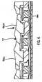
Figs. 5 and6 , thebase 524 also supports adome sheet 542 having a plurality of dome switches 544. Pairs of the dome switches 544 each correspond to:one of the double keys 404-419 and 421, and each of the dome switches 544 corresponds to one of theexternal contact portions 526 of a key 404-421. As such, anexternal contact portion 526 may be pressed to move thecorresponding actuator 534 toward thebase 524 and thereby actuate thecorresponding dome switch 544. For example, the firstexternal contact portion 526a of thedouble key 411 may be pressed to move the correspondingactuator 534a toward thebase 524 and thereby actuate a first dome switch 544a. The secondexternal contact portion 526b of thedouble key 411 may be pressed to move the corresponding actuator 534b toward thebase 524 and thereby actuate a second dome switch 544b. - In some embodiments, each
dome switch 544 comprises a polyethylene terephthalate (PET) film which overlays a collapsible metal dome having a nickel plating over a gold plating on a flexible printed circuit board. When anexternal contact portion 526 is pressed, the dome of the corresponding dome switch collapses thereby connecting conductive platings on an adjacent printed circuit board and completing a connection therebetween. Such an action inputs a signal corresponding to the external contact portion's text or functional character to themobile device 100. - From the above description, it should be appreciated that the double keys are more stable than common "single keys" because each double key has multiple features in contact with the components there below (e.g., the deflection web). These features essentially provide a greater width over which each double key is supported compared to common "single keys". Furthermore, the double keys are less likely to become separated from the device,e.g., if the key assembly is struck by another object.
- Referring now to
Fig. 7 , a block diagram of an exemplarymobile device 100 includingkey assembly 102 is illustrated. Themobile device 100 includes a processing device. 760, acommunications subsystem 762, a short-range communications subsystem 764, input/output devices memory devices other device subsystems 782. Themobile device 100 is preferably a two-way communication device having voice and data communication capabilities. In addition, thedevice 100 preferably has the capability to communicate with other computer systems via the Internet. - The
processing device 760 controls the overall operation of themobile device 100. Operating system software executed by theprocessing device 760 is preferable stored in a persistent store, such as aflash memory 778, but may also be stored in other types of memory devices, such as a read only memory (ROM) or similar storage element. In addition, system software, specific device applications, or parts thereof, may be temporarily loaded into a volatile store, such as a random access memory (RAM) 780. Communication signals received by themobile device 100 may also be stored toRAM 780. - The
processing device 760, in addition to its operating system functions, enables execution ofsoftware applications 778a-778n on thedevice 100. A predetermined set of applications that control basic device operations, such as data andvoice communications device 100 during manufacture. In addition, a personal information manager (PIM) application may be installed during manufacture. The PIM is preferably capable of organizing and managing data items, such as e-mail, calendar events, voice mails, appointments, and task items. The PIM application is also preferably capable of sending and receiving data items via awireless network 784. Preferably, the PIM data items are seamlessly integrated, synchronized and updated via thewireless network 784 with the device user's corresponding data items stored or associated with a host computer system. An example system and method for accomplishing these steps is disclosed in "System And Method For Pushing Information From A Host System To A Mobile Device Having A Shared Electronic Address",U.S. Pat. No. 6,219;694 , which is owned by the assignee of the present application, and which is incorporated herein by reference. - Communication functions, including data and voice communications, are performed through the
communication subsystem 762, and possibly through the short-range communications subsystem 764. Thecommunication subsystem 762 includes areceiver 786, atransmitter 788 and one ormore antennas communication subsystem 762 also includes a processing module, such as a digital signal processor (DSP) 794, and local oscillators (LOs) 796. The specific design and implementation of thecommunication subsystem 762 is dependent upon the communication network in which themobile device 100 is intended to operate. For example, amobile device 100 may include acommunication subsystem 762 designed to operate with the Mobitex™ DataTAC™ or General Packet Radio Service (GPRS) mobile data communication networks and also designed to operated with any of a variety of voice communication networks, such as AMPS, TDMA, CDMA, PCS, GSM, etc. Other types of data and voice networks, both separate and integrated, may also be utilized with themobile device 100. - Network access requirements vary depending upon the type of communication system. For example, in the Mobitex and DataTAC networks, mobile devices are registered on the network using a unique personal identification number or PIN associated with each device. In GPRS networks, however, network access is associated with a subscriber or user of a device. A GPRS device therefore requires a subscriber identity module, commonly referred to as a SIM card, in order to operate on a GPRS, network.
- When required network registration or activation procedures have been completed, the
mobile device 100 may send and receive communication signals over thecommunication network 784. Signals received by theantenna 790 from thecommunication network 784 are routed to thereceiver 786, which provides for signal amplification, frequency down conversion, filtering, channel selection,etc., and may also provide analog to digital conversion. Analog-to-digital conversion of the received signal allows the DSP to perform more complex communication functions, such as demodulation and decoding. In a similar manner, signals to be transmitted to thenetwork 784 are processed (e.g., modulated and encoded) by theDSP 794 and are then provided to thetransmitter 788 for digital to analog conversion, frequency up conversion, filtering, amplification and transmission to the communication network 784 (or networks) via theantenna 792. - In addition to processing communication signals, the
DSP 794 provides forreceiver 786 andtransmitter 788 control. For example, gains applied to communication signals in thereceiver 786 andtransmitter 788 may be adaptively controlled through automatic gain control algorithms implemented in theDSP 794. - In a data communication mode, a received signal, such as a text message or web page download, is processed by the
communication subsystem 762 and input to theprocessing device 760. The received signal is then further processed by theprocessing device 760 for output to adisplay 766, or alternatively to some other auxiliary I/O device 768. A device user may also compose data items, such as e-mail messages, using thekey assembly 102 and/or some other auxiliary I/O device 768, such as a touchpad, a rocker switch, a thumb-wheel, or the like. The composed data items may then be transmitted over thecommunication network 784 via thecommunication subsystem 762. - In a voice communication mode, overall operation of the device is substantially similar to the data communication mode, except that received signals are output to a
speaker 774, and signals for transmission are generated by amicrophone 776. Alternative voice or audio I/O subsystems, such as a voice message recording subsystem, may also be implemented on thedevice 100. In addition, thedisplay 766 may also be utilized in voice communication mode, for example to display the identity of a calling party, the duration of a voice call, or other voice call related information. - The short-
range communications subsystem 764 enables communication between themobile device 100 and other proximate systems or devices, which need not necessarily be similar devices. For example, the short-range communications subsystem 764 may include an infrared device and associated circuits and components, or a Bluetooth™ communication module to provide for communication with similarly-enabled systems and devices.
Claims (10)
- A key assembly (102) for an electronic device, the key assembly (102) comprising:at least one pair of switches (544a, 544b);a deflection web (532) disposed adjacent the at least one pair of switches (544a, 544b), the deflection web (532) including at least one pair of actuators (534a, 534b) and a web connector (536) connecting the at least one pair of actuators (534a, 534b);at least one key (411) supported by the at least one pair of actuators (534a, 534b) opposite the at least one pair of switches (544a, 544b), the at least one key (411) including a body having:a first external contact portion (526a) being movable to move a first actuator (534a) of the at least one pair of actuators (534a, 534b) to thereby actuate a first switch (544a) of the at least one pair of switches (544a, 544b);a second external contact portion (526b) being movable to move a second actuator (534b) of the at least one pair of actuators (534a, 534b) to thereby actuate a second switch (544b) of the at least one pair of switches (544a, 544b);a deflection web support (538) engaging the deflection web (532) and disposed between the deflection web (532) and the at least one pair of switches (544a, 544b); andwherein the body of the at least one key (411) pivots about the first external contact portion (526a) when the second external contact portion (526b) moves to thereby actuate the second switch (544b), and the body of the at least one key (411) pivots about the second external contact portion (526b) when the first external contact portion (526a) moves to thereby actuate the first switch (544a).
- The key assembly of claim 1, wherein the first external contact portion (526a) includes at least one of a text character and a functional character and the second external contact portion (526b) includes at least one of a text character and a functional character.
- The key assembly of claim 1, wherein the deflection web support (538) includes at least one leg (540) disposed between the first actuator (534a) and the second actuator (534b).
- The key assembly of claim 1, further comprising a plurality of keys (404-418) including the at least one key (411), the plurality of keys (404-418) defining three rows, and each of the three rows defining a full row of a keypad layout.
- The key assembly of claim 4, wherein the plurality of keys (404-418) defines the three rows and five columns.
- The key assembly of claim 5, further comprising another plurality of keys (419-421) defining one row and three columns.
- The key assembly of claim 6, wherein the another plurality of keys (419-421) includes a space key (420).
- The key assembly of claim 4, wherein the keypad layout is one of a QWERTY-type keypad layout, a QWERTZ-type keypad layout, an AZERTY-type keypad layout, and a DVORAK-type keypad layout.
- The key assembly of claim 1, wherein the first external contact portion (526a) includes a first post (530a), the first post (530a) contacting the first actuator (534a), and the second external contact portion (526b) includes a second post (530b), the second post (530b) contacting the second actuator (534b).
- The key assembly of claim 1, wherein the first external contact portion (526a) includes a concave contact surface (528a), and the second external contact portion (526b) includes a concave contact surface (528b).
Priority Applications (2)
| Application Number | Priority Date | Filing Date | Title |
|---|---|---|---|
| EP10168743.2AEP2405456B1 (en) | 2010-07-07 | 2010-07-07 | Key assembly for a mobile device |
| CA2745535ACA2745535C (en) | 2010-07-07 | 2011-07-06 | Key assembly for a mobile device |
Applications Claiming Priority (1)
| Application Number | Priority Date | Filing Date | Title |
|---|---|---|---|
| EP10168743.2AEP2405456B1 (en) | 2010-07-07 | 2010-07-07 | Key assembly for a mobile device |
Publications (2)
| Publication Number | Publication Date |
|---|---|
| EP2405456A1 EP2405456A1 (en) | 2012-01-11 |
| EP2405456B1true EP2405456B1 (en) | 2016-10-19 |
Family
ID=43088370
Family Applications (1)
| Application Number | Title | Priority Date | Filing Date |
|---|---|---|---|
| EP10168743.2AActiveEP2405456B1 (en) | 2010-07-07 | 2010-07-07 | Key assembly for a mobile device |
Country Status (2)
| Country | Link |
|---|---|
| EP (1) | EP2405456B1 (en) |
| CA (1) | CA2745535C (en) |
Families Citing this family (1)
| Publication number | Priority date | Publication date | Assignee | Title |
|---|---|---|---|---|
| FR2999785B1 (en)* | 2012-12-17 | 2014-11-28 | Delphi Tech Inc | CONTROL BUTTON |
Family Cites Families (5)
| Publication number | Priority date | Publication date | Assignee | Title |
|---|---|---|---|---|
| US6219694B1 (en) | 1998-05-29 | 2001-04-17 | Research In Motion Limited | System and method for pushing information from a host system to a mobile data communication device having a shared electronic address |
| KR20010054653A (en)* | 1999-12-07 | 2001-07-02 | 오길록 | Telephone keypad with the dual-switch button |
| US20020109614A1 (en)* | 2000-12-22 | 2002-08-15 | Ericsson Inc. | Multi-function key |
| ATE418788T1 (en)* | 2005-02-23 | 2009-01-15 | Research In Motion Ltd | ELECTRONIC HANDHELD DEVICE AND KEYBOARD WITH IMPROVED OPERABILITY AND REDUCED DIMENSIONS AND THEREOF METHOD |
| US8125355B2 (en)* | 2008-06-05 | 2012-02-28 | Sony Ericsson Mobile Communications Ab | Qwerty-keyboard for mobile communication devices |
- 2010
- 2010-07-07EPEP10168743.2Apatent/EP2405456B1/enactiveActive
- 2011
- 2011-07-06CACA2745535Apatent/CA2745535C/enactiveActive
Also Published As
| Publication number | Publication date |
|---|---|
| CA2745535C (en) | 2016-02-16 |
| EP2405456A1 (en) | 2012-01-11 |
| CA2745535A1 (en) | 2012-01-07 |
Similar Documents
| Publication | Publication Date | Title |
|---|---|---|
| EP2302654B1 (en) | A key assembly for an electronic device having one-piece keycaps and multi-touch preventing supports | |
| US8346295B2 (en) | Dual-mode keypad for a mobile device | |
| US8362371B2 (en) | Key assembly for an electronic device having one-piece keycaps and multi-touch preventing supports | |
| EP2367094A1 (en) | Touch sensitive keypad with tactile feedback | |
| US7096036B2 (en) | Dual-mode keypad for a mobile device | |
| US7733330B2 (en) | Mobile device keyboard having three-direction keys | |
| US7286116B2 (en) | Keyboard module | |
| US8492666B2 (en) | Key assembly for a mobile device | |
| US7485816B2 (en) | Switch configuration | |
| US7459646B1 (en) | Keypad assembly and portable electronic device with same | |
| EP1585153A1 (en) | Switch configuration for use with a keyboard | |
| EP2405456B1 (en) | Key assembly for a mobile device | |
| US20020109614A1 (en) | Multi-function key | |
| US8723066B2 (en) | Dome switch device | |
| CA2716036C (en) | A key assembly for an electronic device having a multi-character keycap | |
| CA2738526C (en) | A key assembly for an electronic device having one-piece keycaps and multi-touch preventing supports | |
| US20090289899A1 (en) | Keypad module for character input, electronic devices utilizing the same, and method thereof | |
| EP1679862B1 (en) | Dual-mode keypad for a mobile device | |
| EP2487880B1 (en) | Electronic mobile device having a keypad assembly with a film overlay | |
| US20120208590A1 (en) | Electronic mobile device having a keypad assembly with a film overlay | |
| HK1093128B (en) | Dual-mode keypad for a mobile device | |
| HK1082838B (en) | Switch configuration for use with a keyboard | |
| HK1100710A (en) | Mobile device keyboard having three-direction keys |
Legal Events
| Date | Code | Title | Description |
|---|---|---|---|
| 17P | Request for examination filed | Effective date:20100707 | |
| AK | Designated contracting states | Kind code of ref document:A1 Designated state(s):AL AT BE BG CH CY CZ DE DK EE ES FI FR GB GR HR HU IE IS IT LI LT LU LV MC MK MT NL NO PL PT RO SE SI SK SM TR | |
| AX | Request for extension of the european patent | Extension state:BA ME RS | |
| PUAI | Public reference made under article 153(3) epc to a published international application that has entered the european phase | Free format text:ORIGINAL CODE: 0009012 | |
| RAP1 | Party data changed (applicant data changed or rights of an application transferred) | Owner name:BLACKBERRY LIMITED | |
| RAP1 | Party data changed (applicant data changed or rights of an application transferred) | Owner name:BLACKBERRY LIMITED | |
| GRAP | Despatch of communication of intention to grant a patent | Free format text:ORIGINAL CODE: EPIDOSNIGR1 | |
| RIC1 | Information provided on ipc code assigned before grant | Ipc:H01H 13/705 20060101AFI20160405BHEP | |
| INTG | Intention to grant announced | Effective date:20160428 | |
| GRAS | Grant fee paid | Free format text:ORIGINAL CODE: EPIDOSNIGR3 | |
| GRAA | (expected) grant | Free format text:ORIGINAL CODE: 0009210 | |
| AK | Designated contracting states | Kind code of ref document:B1 Designated state(s):AL AT BE BG CH CY CZ DE DK EE ES FI FR GB GR HR HU IE IS IT LI LT LU LV MC MK MT NL NO PL PT RO SE SI SK SM TR | |
| REG | Reference to a national code | Ref country code:GB Ref legal event code:FG4D | |
| REG | Reference to a national code | Ref country code:CH Ref legal event code:EP | |
| REG | Reference to a national code | Ref country code:AT Ref legal event code:REF Ref document number:838963 Country of ref document:AT Kind code of ref document:T Effective date:20161115 | |
| REG | Reference to a national code | Ref country code:IE Ref legal event code:FG4D | |
| REG | Reference to a national code | Ref country code:DE Ref legal event code:R096 Ref document number:602010037270 Country of ref document:DE | |
| REG | Reference to a national code | Ref country code:NL Ref legal event code:FP | |
| REG | Reference to a national code | Ref country code:LT Ref legal event code:MG4D | |
| PG25 | Lapsed in a contracting state [announced via postgrant information from national office to epo] | Ref country code:LV Free format text:LAPSE BECAUSE OF FAILURE TO SUBMIT A TRANSLATION OF THE DESCRIPTION OR TO PAY THE FEE WITHIN THE PRESCRIBED TIME-LIMIT Effective date:20161019 | |
| REG | Reference to a national code | Ref country code:AT Ref legal event code:MK05 Ref document number:838963 Country of ref document:AT Kind code of ref document:T Effective date:20161019 | |
| PG25 | Lapsed in a contracting state [announced via postgrant information from national office to epo] | Ref country code:SE Free format text:LAPSE BECAUSE OF FAILURE TO SUBMIT A TRANSLATION OF THE DESCRIPTION OR TO PAY THE FEE WITHIN THE PRESCRIBED TIME-LIMIT Effective date:20161019 Ref country code:GR Free format text:LAPSE BECAUSE OF FAILURE TO SUBMIT A TRANSLATION OF THE DESCRIPTION OR TO PAY THE FEE WITHIN THE PRESCRIBED TIME-LIMIT Effective date:20170120 Ref country code:LT Free format text:LAPSE BECAUSE OF FAILURE TO SUBMIT A TRANSLATION OF THE DESCRIPTION OR TO PAY THE FEE WITHIN THE PRESCRIBED TIME-LIMIT Effective date:20161019 Ref country code:NO Free format text:LAPSE BECAUSE OF FAILURE TO SUBMIT A TRANSLATION OF THE DESCRIPTION OR TO PAY THE FEE WITHIN THE PRESCRIBED TIME-LIMIT Effective date:20170119 | |
| PG25 | Lapsed in a contracting state [announced via postgrant information from national office to epo] | Ref country code:PL Free format text:LAPSE BECAUSE OF FAILURE TO SUBMIT A TRANSLATION OF THE DESCRIPTION OR TO PAY THE FEE WITHIN THE PRESCRIBED TIME-LIMIT Effective date:20161019 Ref country code:BE Free format text:LAPSE BECAUSE OF FAILURE TO SUBMIT A TRANSLATION OF THE DESCRIPTION OR TO PAY THE FEE WITHIN THE PRESCRIBED TIME-LIMIT Effective date:20161019 Ref country code:HR Free format text:LAPSE BECAUSE OF FAILURE TO SUBMIT A TRANSLATION OF THE DESCRIPTION OR TO PAY THE FEE WITHIN THE PRESCRIBED TIME-LIMIT Effective date:20161019 Ref country code:PT Free format text:LAPSE BECAUSE OF FAILURE TO SUBMIT A TRANSLATION OF THE DESCRIPTION OR TO PAY THE FEE WITHIN THE PRESCRIBED TIME-LIMIT Effective date:20170220 Ref country code:AT Free format text:LAPSE BECAUSE OF FAILURE TO SUBMIT A TRANSLATION OF THE DESCRIPTION OR TO PAY THE FEE WITHIN THE PRESCRIBED TIME-LIMIT Effective date:20161019 Ref country code:ES Free format text:LAPSE BECAUSE OF FAILURE TO SUBMIT A TRANSLATION OF THE DESCRIPTION OR TO PAY THE FEE WITHIN THE PRESCRIBED TIME-LIMIT Effective date:20161019 Ref country code:IS Free format text:LAPSE BECAUSE OF FAILURE TO SUBMIT A TRANSLATION OF THE DESCRIPTION OR TO PAY THE FEE WITHIN THE PRESCRIBED TIME-LIMIT Effective date:20170219 Ref country code:FI Free format text:LAPSE BECAUSE OF FAILURE TO SUBMIT A TRANSLATION OF THE DESCRIPTION OR TO PAY THE FEE WITHIN THE PRESCRIBED TIME-LIMIT Effective date:20161019 | |
| REG | Reference to a national code | Ref country code:DE Ref legal event code:R097 Ref document number:602010037270 Country of ref document:DE | |
| REG | Reference to a national code | Ref country code:FR Ref legal event code:PLFP Year of fee payment:8 | |
| PG25 | Lapsed in a contracting state [announced via postgrant information from national office to epo] | Ref country code:SK Free format text:LAPSE BECAUSE OF FAILURE TO SUBMIT A TRANSLATION OF THE DESCRIPTION OR TO PAY THE FEE WITHIN THE PRESCRIBED TIME-LIMIT Effective date:20161019 Ref country code:RO Free format text:LAPSE BECAUSE OF FAILURE TO SUBMIT A TRANSLATION OF THE DESCRIPTION OR TO PAY THE FEE WITHIN THE PRESCRIBED TIME-LIMIT Effective date:20161019 Ref country code:CZ Free format text:LAPSE BECAUSE OF FAILURE TO SUBMIT A TRANSLATION OF THE DESCRIPTION OR TO PAY THE FEE WITHIN THE PRESCRIBED TIME-LIMIT Effective date:20161019 Ref country code:DK Free format text:LAPSE BECAUSE OF FAILURE TO SUBMIT A TRANSLATION OF THE DESCRIPTION OR TO PAY THE FEE WITHIN THE PRESCRIBED TIME-LIMIT Effective date:20161019 Ref country code:EE Free format text:LAPSE BECAUSE OF FAILURE TO SUBMIT A TRANSLATION OF THE DESCRIPTION OR TO PAY THE FEE WITHIN THE PRESCRIBED TIME-LIMIT Effective date:20161019 | |
| PLBE | No opposition filed within time limit | Free format text:ORIGINAL CODE: 0009261 | |
| STAA | Information on the status of an ep patent application or granted ep patent | Free format text:STATUS: NO OPPOSITION FILED WITHIN TIME LIMIT | |
| PG25 | Lapsed in a contracting state [announced via postgrant information from national office to epo] | Ref country code:IT Free format text:LAPSE BECAUSE OF FAILURE TO SUBMIT A TRANSLATION OF THE DESCRIPTION OR TO PAY THE FEE WITHIN THE PRESCRIBED TIME-LIMIT Effective date:20161019 Ref country code:SM Free format text:LAPSE BECAUSE OF FAILURE TO SUBMIT A TRANSLATION OF THE DESCRIPTION OR TO PAY THE FEE WITHIN THE PRESCRIBED TIME-LIMIT Effective date:20161019 Ref country code:BG Free format text:LAPSE BECAUSE OF FAILURE TO SUBMIT A TRANSLATION OF THE DESCRIPTION OR TO PAY THE FEE WITHIN THE PRESCRIBED TIME-LIMIT Effective date:20170119 | |
| 26N | No opposition filed | Effective date:20170720 | |
| PG25 | Lapsed in a contracting state [announced via postgrant information from national office to epo] | Ref country code:SI Free format text:LAPSE BECAUSE OF FAILURE TO SUBMIT A TRANSLATION OF THE DESCRIPTION OR TO PAY THE FEE WITHIN THE PRESCRIBED TIME-LIMIT Effective date:20161019 | |
| REG | Reference to a national code | Ref country code:CH Ref legal event code:PL | |
| REG | Reference to a national code | Ref country code:IE Ref legal event code:MM4A | |
| PG25 | Lapsed in a contracting state [announced via postgrant information from national office to epo] | Ref country code:LI Free format text:LAPSE BECAUSE OF NON-PAYMENT OF DUE FEES Effective date:20170731 Ref country code:IE Free format text:LAPSE BECAUSE OF NON-PAYMENT OF DUE FEES Effective date:20170707 Ref country code:CH Free format text:LAPSE BECAUSE OF NON-PAYMENT OF DUE FEES Effective date:20170731 | |
| PG25 | Lapsed in a contracting state [announced via postgrant information from national office to epo] | Ref country code:LU Free format text:LAPSE BECAUSE OF NON-PAYMENT OF DUE FEES Effective date:20170707 | |
| REG | Reference to a national code | Ref country code:FR Ref legal event code:PLFP Year of fee payment:9 | |
| PG25 | Lapsed in a contracting state [announced via postgrant information from national office to epo] | Ref country code:MT Free format text:LAPSE BECAUSE OF NON-PAYMENT OF DUE FEES Effective date:20170707 | |
| PG25 | Lapsed in a contracting state [announced via postgrant information from national office to epo] | Ref country code:MC Free format text:LAPSE BECAUSE OF FAILURE TO SUBMIT A TRANSLATION OF THE DESCRIPTION OR TO PAY THE FEE WITHIN THE PRESCRIBED TIME-LIMIT Effective date:20161019 Ref country code:HU Free format text:LAPSE BECAUSE OF FAILURE TO SUBMIT A TRANSLATION OF THE DESCRIPTION OR TO PAY THE FEE WITHIN THE PRESCRIBED TIME-LIMIT; INVALID AB INITIO Effective date:20100707 | |
| PG25 | Lapsed in a contracting state [announced via postgrant information from national office to epo] | Ref country code:CY Free format text:LAPSE BECAUSE OF NON-PAYMENT OF DUE FEES Effective date:20161019 | |
| PG25 | Lapsed in a contracting state [announced via postgrant information from national office to epo] | Ref country code:MK Free format text:LAPSE BECAUSE OF FAILURE TO SUBMIT A TRANSLATION OF THE DESCRIPTION OR TO PAY THE FEE WITHIN THE PRESCRIBED TIME-LIMIT Effective date:20161019 | |
| PG25 | Lapsed in a contracting state [announced via postgrant information from national office to epo] | Ref country code:TR Free format text:LAPSE BECAUSE OF FAILURE TO SUBMIT A TRANSLATION OF THE DESCRIPTION OR TO PAY THE FEE WITHIN THE PRESCRIBED TIME-LIMIT Effective date:20161019 | |
| PG25 | Lapsed in a contracting state [announced via postgrant information from national office to epo] | Ref country code:AL Free format text:LAPSE BECAUSE OF FAILURE TO SUBMIT A TRANSLATION OF THE DESCRIPTION OR TO PAY THE FEE WITHIN THE PRESCRIBED TIME-LIMIT Effective date:20161019 | |
| REG | Reference to a national code | Ref country code:DE Ref legal event code:R082 Ref document number:602010037270 Country of ref document:DE Ref country code:DE Ref legal event code:R081 Ref document number:602010037270 Country of ref document:DE Owner name:MALIKIE INNOVATIONS LTD., IE Free format text:FORMER OWNER: BLACKBERRY LIMITED, WATERLOO, ONTARIO, CA | |
| PGFP | Annual fee paid to national office [announced via postgrant information from national office to epo] | Ref country code:DE Payment date:20240730 Year of fee payment:15 | |
| PGFP | Annual fee paid to national office [announced via postgrant information from national office to epo] | Ref country code:GB Payment date:20240724 Year of fee payment:15 | |
| PGFP | Annual fee paid to national office [announced via postgrant information from national office to epo] | Ref country code:FR Payment date:20240725 Year of fee payment:15 | |
| PGFP | Annual fee paid to national office [announced via postgrant information from national office to epo] | Ref country code:NL Payment date:20250724 Year of fee payment:16 |