EP2405439B1 - Magnetic device with optimized heat confinement - Google Patents
Magnetic device with optimized heat confinementDownload PDFInfo
- Publication number
- EP2405439B1 EP2405439B1EP10290375AEP10290375AEP2405439B1EP 2405439 B1EP2405439 B1EP 2405439B1EP 10290375 AEP10290375 AEP 10290375AEP 10290375 AEP10290375 AEP 10290375AEP 2405439 B1EP2405439 B1EP 2405439B1
- Authority
- EP
- European Patent Office
- Prior art keywords
- magnetic
- tunnel junction
- magnetic tunnel
- insulating layer
- thermal insulating
- Prior art date
- Legal status (The legal status is an assumption and is not a legal conclusion. Google has not performed a legal analysis and makes no representation as to the accuracy of the status listed.)
- Active
Links
- 230000005291magnetic effectEffects0.000titleclaimsdescription204
- 230000004888barrier functionEffects0.000claimsdescription64
- 238000010438heat treatmentMethods0.000claimsdescription24
- 239000000463materialSubstances0.000claimsdescription18
- 230000005415magnetizationEffects0.000claimsdescription17
- 238000003860storageMethods0.000description18
- 238000009826distributionMethods0.000description9
- VYPSYNLAJGMNEJ-UHFFFAOYSA-NSilicium dioxideChemical compoundO=[Si]=OVYPSYNLAJGMNEJ-UHFFFAOYSA-N0.000description8
- 238000004519manufacturing processMethods0.000description8
- 230000005290antiferromagnetic effectEffects0.000description7
- 239000011810insulating materialSubstances0.000description7
- 230000000903blocking effectEffects0.000description6
- 229910045601alloyInorganic materials0.000description5
- 239000000956alloySubstances0.000description5
- 238000005381potential energyMethods0.000description5
- MCMNRKCIXSYSNV-UHFFFAOYSA-NZirconium dioxideChemical compoundO=[Zr]=OMCMNRKCIXSYSNV-UHFFFAOYSA-N0.000description4
- 239000000377silicon dioxideSubstances0.000description4
- 229910052681coesiteInorganic materials0.000description3
- 229910052906cristobaliteInorganic materials0.000description3
- 230000006870functionEffects0.000description3
- 230000017525heat dissipationEffects0.000description3
- 229910052742ironInorganic materials0.000description3
- CPLXHLVBOLITMK-UHFFFAOYSA-Nmagnesium oxideInorganic materials[Mg]=OCPLXHLVBOLITMK-UHFFFAOYSA-N0.000description3
- 229910052682stishoviteInorganic materials0.000description3
- 229910052905tridymiteInorganic materials0.000description3
- -1BiTeChemical compound0.000description2
- 229910003321CoFeInorganic materials0.000description2
- BOTDANWDWHJENH-UHFFFAOYSA-NTetraethyl orthosilicateChemical compoundCCO[Si](OCC)(OCC)OCCBOTDANWDWHJENH-UHFFFAOYSA-N0.000description2
- 238000004364calculation methodMethods0.000description2
- 230000000694effectsEffects0.000description2
- 230000005294ferromagnetic effectEffects0.000description2
- 239000000395magnesium oxideSubstances0.000description2
- 229910052748manganeseInorganic materials0.000description2
- 229910052759nickelInorganic materials0.000description2
- 229920003209poly(hydridosilsesquioxane)Polymers0.000description2
- 235000012239silicon dioxideNutrition0.000description2
- 238000004088simulationMethods0.000description2
- 230000005418spin waveEffects0.000description2
- OKTJSMMVPCPJKN-UHFFFAOYSA-NCarbonChemical compound[C]OKTJSMMVPCPJKN-UHFFFAOYSA-N0.000description1
- 229910015136FeMnInorganic materials0.000description1
- PXGOKWXKJXAPGV-UHFFFAOYSA-NFluorineChemical compoundFFPXGOKWXKJXAPGV-UHFFFAOYSA-N0.000description1
- 229910000618GeSbTeInorganic materials0.000description1
- 229910005900GeTeInorganic materials0.000description1
- 229910019041PtMnInorganic materials0.000description1
- 229910018321SbTeInorganic materials0.000description1
- 229910004541SiNInorganic materials0.000description1
- PNEYBMLMFCGWSK-UHFFFAOYSA-Naluminium oxideInorganic materials[O-2].[O-2].[O-2].[Al+3].[Al+3]PNEYBMLMFCGWSK-UHFFFAOYSA-N0.000description1
- 229910052797bismuthInorganic materials0.000description1
- JCXGWMGPZLAOME-UHFFFAOYSA-Nbismuth atomChemical compound[Bi]JCXGWMGPZLAOME-UHFFFAOYSA-N0.000description1
- 229910052799carbonInorganic materials0.000description1
- 238000001816coolingMethods0.000description1
- 239000003989dielectric materialSubstances0.000description1
- 239000003302ferromagnetic materialSubstances0.000description1
- 229910052731fluorineInorganic materials0.000description1
- 239000011737fluorineSubstances0.000description1
- 230000002401inhibitory effectEffects0.000description1
- 229910052741iridiumInorganic materials0.000description1
- AXZKOIWUVFPNLO-UHFFFAOYSA-Nmagnesium;oxygen(2-)Chemical compound[O-2].[Mg+2]AXZKOIWUVFPNLO-UHFFFAOYSA-N0.000description1
- 239000000696magnetic materialSubstances0.000description1
- 238000000034methodMethods0.000description1
- 125000002496methyl groupChemical group[H]C([H])([H])*0.000description1
- 229910052714telluriumInorganic materials0.000description1
- PORWMNRCUJJQNO-UHFFFAOYSA-Ntellurium atomChemical compound[Te]PORWMNRCUJJQNO-UHFFFAOYSA-N0.000description1
- RUDFQVOCFDJEEF-UHFFFAOYSA-Nyttrium(III) oxideInorganic materials[O-2].[O-2].[O-2].[Y+3].[Y+3]RUDFQVOCFDJEEF-UHFFFAOYSA-N0.000description1
Images


Classifications
- G—PHYSICS
- G11—INFORMATION STORAGE
- G11C—STATIC STORES
- G11C11/00—Digital stores characterised by the use of particular electric or magnetic storage elements; Storage elements therefor
- G11C11/02—Digital stores characterised by the use of particular electric or magnetic storage elements; Storage elements therefor using magnetic elements
- G11C11/16—Digital stores characterised by the use of particular electric or magnetic storage elements; Storage elements therefor using magnetic elements using elements in which the storage effect is based on magnetic spin effect
- B—PERFORMING OPERATIONS; TRANSPORTING
- B82—NANOTECHNOLOGY
- B82Y—SPECIFIC USES OR APPLICATIONS OF NANOSTRUCTURES; MEASUREMENT OR ANALYSIS OF NANOSTRUCTURES; MANUFACTURE OR TREATMENT OF NANOSTRUCTURES
- B82Y25/00—Nanomagnetism, e.g. magnetoimpedance, anisotropic magnetoresistance, giant magnetoresistance or tunneling magnetoresistance
- G—PHYSICS
- G11—INFORMATION STORAGE
- G11C—STATIC STORES
- G11C11/00—Digital stores characterised by the use of particular electric or magnetic storage elements; Storage elements therefor
- G11C11/02—Digital stores characterised by the use of particular electric or magnetic storage elements; Storage elements therefor using magnetic elements
- G11C11/16—Digital stores characterised by the use of particular electric or magnetic storage elements; Storage elements therefor using magnetic elements using elements in which the storage effect is based on magnetic spin effect
- G11C11/165—Auxiliary circuits
- G11C11/1675—Writing or programming circuits or methods
- H—ELECTRICITY
- H01—ELECTRIC ELEMENTS
- H01F—MAGNETS; INDUCTANCES; TRANSFORMERS; SELECTION OF MATERIALS FOR THEIR MAGNETIC PROPERTIES
- H01F10/00—Thin magnetic films, e.g. of one-domain structure
- H01F10/32—Spin-exchange-coupled multilayers, e.g. nanostructured superlattices
- H01F10/324—Exchange coupling of magnetic film pairs via a very thin non-magnetic spacer, e.g. by exchange with conduction electrons of the spacer
- H01F10/3254—Exchange coupling of magnetic film pairs via a very thin non-magnetic spacer, e.g. by exchange with conduction electrons of the spacer the spacer being semiconducting or insulating, e.g. for spin tunnel junction [STJ]
Definitions
- the present disclosureconcerns a magnetic element comprising a magnetic tunnel junction that can be written by using a thermally assisted switching write operation and a magnetic memory device comprising a plurality of the magnetic element.
- the magnetic element 1comprises a magnetic tunnel junction 2 formed from a tunnel barrier 22 being disposed between a first magnetic layer, or reference layer 21, and a second magnetic layer, or storage layer 23.
- the magnetic element 1further comprises an upper current line 4 connected at the upper end of the magnetic tunnel junction 2, and a strap portion 7 extending laterally and substantially parallel to the first and second magnetic layers 21, 23 and connecting the bottom end of the magnetic tunnel junction 2 to a select transistor 3.
- the configuration strap portion 7is advantageous for disposing a bottom current line 5 which uses will be discussed below.
- the reference layer 21can be formed from a Fe, Co or Ni based alloy and have a first magnetization that having a fixed magnetization direction.
- the first magnetizationcan be fixed in any conventional manner, such as by using a high coercivity (or large switching magnetic field) material.
- the direction of the first magnetizationcan be fixed by being exchange-coupled to an antiferromagnetic reference layer (not shown) pinning the first magnetization at a low threshold temperature, below the reference blocking temperature T BR of the antiferromagnetic reference layer.
- the tunnel barrier 22is a thin layer, typically in the nanometer range and is formed, for example, from any suitable insulating material, such as alumina or magnesium oxide.
- the tunnel barrier 22has typically a resistance-area product smaller than 50 ⁇ ⁇ m 2 .
- the storage layer 23can have a second magnetization which direction can be freely adjusted when the magnetic tunnel junction 2 is heated at a high threshold temperature.
- the storage layer 23can be a layer of ferromagnetic material typically including Fe, Co, Ni or their alloys.
- the storage layer 23can be exchange-coupled with an adjacent antiferromagnetic storage layer (not shown) pinning the storage layer 23 at a temperature below a storage blocking temperature T BS of the antiferromagnetic storage layer, where T BS is preferably smaller than the storage blocking temperature T BR .
- the antiferromagnetic storage layercan be made of an alloy of Fe and Mn, such as FeMn, or Ir and Mn, for example, an alloy containing 20% of Ir and 80% of Mn.
- the storage blocking temperature T BScan be typically comprised between 150°C and 250°.
- the magnetic tunnel junction 2is heated at the high threshold temperature, above T BS but below T BR , by applying a heating current 31 to the magnetic tunnel junction 2.
- the heating current 31can be applied via the current line 4, when the select transistor 3 is in the passing mode.
- the direction of the second magnetizationcan be adjusted by by passing a spin polarized electric current or a current induced magnetic switching (CIMS) in the magnetic tunnel junction 2, or by using an external magnetic field 52 as shown in Fig. 1 . In the latter case, the external magnetic field 52 can be generated by a passing a field current 51 in the bottom current line 5.
- CIMScurrent induced magnetic switching
- the second magnetizationcan be oriented such as to be substantial parallel or antiparallel (as in the example of Fig. 1 ) with the first magnetization direction.
- the second magnetizationis then frozen in its switched direction by inhibiting the heating current 31, cooling the magnetic tunnel junction 2 at a low threshold temperature, below T BS .
- the resistance of the magnetic tunnel junction 2can be measured by passing a sense current (not shown) through it.
- the measured resistancevaries depending on the relative directions of the first and second magnetizations. A high resistance is measured when the first magnetization is oriented substantially antiparallel with the second magnetization and a small resistance is measure when the first and second magnetizations are oriented substantially parallel.
- Passing the heating current 31 for heating the magnetic tunnel junction 20 to the predetermined high temperature thresholdrequires applying a voltage V heat , having a possibly high value, between the reference and storage layers 1, 4.
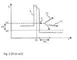
- the potential energy Eis plotted against a distance X along the magnetic tunnel junction 2, representing the potential energy function 8 of the electrons in the magnetic tunnel junction 2 subjected to a potential V heat , generated when the heating current 31 is passed in the magnetic tunnel junction 2.
- the reference and storage layers 21, 23are located on each side of the tunnel barrier 22, placed at X0.
- the reference and storage layers 21, 23behave like an electron-emitting layer having an upper Fermi level Efs, and an electron-receiving layer having a lower Fermi level Efi, respectively.
- Efs-EfieV, e being the elementary charge of the electron.
- Efs-EfieV, e being the elementary charge of the electron.
- Inelastic relaxationtakes place over a characteristic length, or inelastic mean free path, ⁇ in , which length is typically about a few nanometers in the magnetic materials usually used in typical magnetic tunnel junctions.
- Heat production by the electrons passing through the tunnel barrier 22, or tunnel current (not shown)is thus maximal in a zone with a thickness of a few nanometers, located in the receiving layer and adjacent to the tunnel barrier 22. Since the potential V heat used for heating the magnetic tunnel junction 2 at the high temperature threshold can be high, such heat production can damage the magnetic tunnel junction 2.
- Fig. 3illustrates the magnetic element 1 according to European Patent Application No. 1,671,330 , where the magnetic tunnel junction 2 further comprises an upper thermal barrier 14 placed between the current line 4 and the reference layer 21, and a bottom thermal barrier 15, between the storage layer 23 and the strap portion 7.
- a bottom electrode 16is represented, connected to the strap portion 7 through a bottom via 17.
- the select transistor 3, not represented in Fig. 3can be connected to the bottom electrode 16 or directly to the bottom via 17.
- the upper and bottom thermal barrier 14, 15advantageously reduce heat losses at both upper and bottom ends of the magnetic tunnel junction 2, when the heating current 31 is passed. Consequently, a more efficient heating of the magnetic tunnel junction 20 is achieved and the heating current 31, or potential V heat , needed for heating the magnetic tunnel junction 20 can be lowered.
- thermal barriers 14, 15are connected in series with the tunnel barrier 22, their electrical conductivity must be high enough compared to that of the tunnel barrier 22 to ensure that the electrical current flows uniquely through the magnetic tunnel junction 2.
- the electrical conductivity of the thermal barriers 14, 15is higher by a factor ten compared with that of the tunnel barrier 22. This limits the possibility of using material with very low thermal conductivity for the thermal barriers 14, 15.
- thermal barriersare made from an alloy containing Bismuth (Bi) and Tellurium (Te), such as BiTe, which exhibits an electric conductivity of about 1.75 m ⁇ -cm and a thermal conductivity of about 1.5 W m -1 °C -1 .
- the present disclosureconcerns a magnetic element which overcomes at least some limitations of the prior art.
- a magnetic element to be written using a thermally-assisted switching write operationcan comprise a magnetic tunnel junction formed from a tunnel barrier being disposed between first and second magnetic layers, said second magnetic layer having a second magnetization which direction can be adjusted during a write operation when the magnetic tunnel junction is heated at a high threshold temperature; an upper current line connected at the upper end of the magnetic tunnel junction; and a strap portion extending laterally and connected to the bottom end of the magnetic tunnel junction; wherein the magnetic device can further comprise a bottom thermal insulating layer extending substantially parallel to the strap portion and arranged such that the strap portion is between the magnetic tunnel junction and the bottom thermal insulating layer, for lowering heat losses in the magnetic tunnel junction during the write operation as compared to with the magnetic tunnel junction without the bottom thermal insulating layer.
- the magnetic elementcan further comprise an upper thermal insulating layer arranged at the upper end of the magnetic tunnel junction, between the upper current line and the magnetic tunnel junction.
- the magnetic elementcan further comprise a lateral thermal insulating layer, laterally embedding at least a portion of the magnetic tunnel junction.
- said at least a portion of the magnetic tunnel junctioncan comprise the bottom magnetic layer, the upper magnetic layer, the tunnel barrier, or a combination of any of them.
- said at least a portion of the magnetic tunnel junctioncan comprise the whole magnetic tunnel junction.
- the thermal insulating layercan have a thermal conductivity lower than 1.0Wm -1 °C -1 .
- the thermal insulating layercan be made from a low-K material.
- the magnetic tunnel junctioncan further comprise an upper thermal barrier between the upper current line and the magnetic tunnel junction, and a bottom thermal barrier between the magnetic tunnel junction and the strap portion.
- the longitudinal thermal barrierscan have an electrical resistance lower than the electrical resistance of the tunnel barrier by a factor of at least ten.
- the magnetic tunnel junctioncan comprise an electrically insulating liner layer embedding the magnetic tunnel junction.
- the magnetic elementcan further comprise a select transistor connected at the lower end of the magnetic tunnel junction via the strap portion and that can be activated to apply a heating current to said magnetic tunnel junction via the upper current line, for heating magnetic tunnel junction at the high threshold temperature.
- the present disclosurealso pertains to a magnetic memory device comprising a plurality of the magnetic element where one or a plurality of the current line being coupled to said plurality of the magnetic element via their magnetic tunnel junction, and comprising one or a plurality of control current lines coupled to the magnetic elements via their select transistor.
- the magnetic element disclosed hereinallows for reducing heat losses more effectively compared to conventional magnetic elements using a thermal barrier between the upper current line and the magnetic tunnel junction and/or between the strap portion and the magnetic tunnel junction.
- the thermal insulating layercan be easily integrated into the manufacturing process of the magnetic element, without increasing the complexity of the manufacturing process.
- the magnetic element and memory device of the inventioncan then be used with a smaller heating current than the one used in conventional magnetic element and memory device, thus reducing power consumption and improving the endurance of the magnetic element.
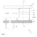
- a magnetic element 1is represented in Fig. 4 according to an embodiment.
- the magnetic element 1comprises a magnetic tunnel junction 2 formed from a tunnel barrier 22 being disposed between first and second magnetic layers 21, 23.
- the second magnetic layer 23has a second magnetization which direction can be adjusted during a write operation when the magnetic tunnel junction 2 is heated at a high threshold temperature.
- the magnetic element 1also comprises an upper current line 4 connected at the upper end of the magnetic tunnel junction 2, and a metallic strap portion 7 extending laterally substantially parallel to the first and second magnetic layers 21, 23 and connecting the bottom end of the magnetic tunnel junction 2 to a bottom electrode 16 though a bottom via 17.
- the memory cell 1further comprises a bottom thermal insulating layer 28 extending below the strap portion 7 and substantially parallel to it.
- the strap portion 7is between the magnetic tunnel junction 2 and the bottom thermal insulating layer 28, the latter contacting the strap portion 7 along its bottom surface 7'.
- the magnetic tunnel junction 2can be laterally embedded in a conventional insulating material 27 such as SiO 2 or TEOS.
- the strap portion 7is in electrical contact with the bottom electrode through the metallic via 17, and the bottom thermal insulating layer 28 is therefore not placed in the electrical path of the magnetic tunnel junction 2.
- the bottom thermal insulating layer 28is not connected in series with the tunnel barrier 22, it can be made of a material having an electric conductivity that is much lower than the one typically used for the thermal barriers 14, 15.
- the bottom thermal insulating layer 28can have an electrical conductivity that is below 10 -14 S/cm.
- the bottom thermal insulating layer 28is made from a low-K material having a thermal conductivity below 1.0 W m -1 °C -1 and that can be integrated into the manufacturing process of the magnetic element 1.
- the bottom thermal insulating layer 28can be made of a material which offers low thermal conductivity such as porous SiO2, SiN, or zirconia (yttria stabilized ZrO 2 ) having a thermal conductivity, at 20°C, of about 0.025 W m -1 °C -1 .
- the low thermal conductivity materialcan also be a GST like material offering low thermal conductivity in its amorphous high resistive state.
- GST like materialmay consist of a chalcogenide compound material, such as GeSbTe, SbTe, GeTe or AglnSbTe.
- the bottom thermal insulating layer 28is made from a low-K material comprising fluorine or carbon doped silicon dioxide, hydrogenated silicon oxycarbide (SiCOH) having a thermal conductivity of approximately 0.21 W m -1 °C -1 , porous SiCOH, porous methyl silsesquioxane (MSQ), porous hydrogen silsesquioxane (HSQ), spin-on organic polymeric dielectrics, or a combination of any of them.
- the expression "low k”preferably means any material having a dielectric constant less than approximately 3.9.
- the bottom thermal insulating layer 28having a lower thermal conductivity than the one the thermal barrier 14, 15, possibly up to about sixty times lower depending on the material used for the bottom thermal insulating layer 28, it allows for reducing heat dissipation in the magnetic tunnel junction 2 more effectively than in conventional magnetic elements using the thermal barrier 14, 15. Moreover, due to its placement, the bottom thermal insulating layer 28 can effectively block the heat dissipated from the metallic strap portion 7 that acts like a large heat dissipating area due to its high thermal conductivity and its relatively large size compared to the size of the magnetic tunnel junction 2. The bottom thermal insulating layer 28 can be easily integrated into the manufacturing process of the magnetic element 1, without increasing the complexity of the manufacturing process.
- the magnetic element 1further comprises an upper thermal insulating layer 32, arranged at the upper end of the magnetic tunnel junction 2, between the upper current line 4 and the magnetic tunnel junction 2, and extending substantially parallel to strap portion 7.
- an upper via 18connects the upper current line 4 to the magnetic tunnel junction 2 and the upper thermal insulating layer 32 is not in the electrical path of the magnetic tunnel junction 2.
- the upper thermal insulating layer 32further reduces heat dissipation from the magnetic tunnel junction 2.
- the magnetic element 1can comprise the upper thermal insulating layer 32 alone, without the bottom thermal insulating layer 28. During the TAS write operation, the bottom thermal insulating layer 28, and possibly upper thermal insulating layer 32, will reduce dissipation of the heat produced by the heating current 31 in the magnetic tunnel junction 2.
- the magnetic tunnel junction 2further comprises the bottom and/or upper thermal barrier 14, 15 described above, at the bottom and upper end of the magnetic tunnel junction 2.
- the magnetic element 1further comprises a lateral thermal insulating layer 30, laterally embedding at least a portion of the magnetic tunnel junction 2.
- a lateral thermal insulating layer 30can be made from the same material as the one used of the bottom and/or upper thermal insulating layer 28, 32, for example a low-K material.
- the lateral thermal insulating layer 30can realized by the bottom and/or upper thermal insulating layer 28, 32 extending upwards and/or downwards, along the magnetic tunnel junction 2. Examples of Figs. 4 and 5 show the magnetic element 1 where the conventional insulating material 27 has been replaced by the lateral thermal insulating layer 30, the latter embeds the whole magnetic tunnel junction 2.
- the portion of the magnetic tunnel junction 2 embedded by the lateral thermal insulating layer 30can comprise the bottom magnetic layer 23, the upper magnetic layer 21, the tunnel barrier 22, the bottom and upper thermal barrier 14, 15 if present, or a combination of any of them.
- the rest of the magnetic tunnel junction 2can be laterally embedded in the conventional insulating material 27, such as SiO 2 or TEOS.
- the magnetic tunnel junction 2is surrounded by a thin liner.
- the lineris typically made of a material having a etch rate that is lower than the one of the magnetic tunnel junction 2.
- the lineris a thin layer extending along the magnetic tunnel junction 2, and disposed between the magnetic tunnel junction 2 and the lateral thermal insulating barrier 30 and/or the conventional insulating material 27.
- the use of the linercan be advantageous during the fabrication process, especially when the magnetic tunnel junction 2 is etched in more than one step. For example, the liner can protect a first etched portion of the magnetic tunnel junction 2 when a second portion is being etched.
- the lateral thermal insulating barrier 30can further confine the heat produced by the heating current 31 between the sidewalls of the magnetic tunnel junction 2, resulting in further reducing heat dissipation. Moreover, since the electrical conductivity of the lateral thermal insulating layer 30 can be as low or lower that the electrical conductivity of the tunnel barrier 3, the lateral thermal insulating barrier 30 can reduce the electrical capacitance between the first, second layers 21, 23 and the tunnel barrier 22.
- Figs. 6 and 7compare the temperature distribution simulated for the magnetic element 1 comprising the bottom thermal insulating barrier 28 (plain curves in Fig. 6 and 7 ) and without it (dashed curves in Fig. 6 and 7 ). Calculations were performed assuming the magnetic tunnel junction 2 having a diameter of 0.2 ⁇ m in which the heating current 31 is passed as a current pulse of 20ns, the temperature distribution being shown at the end of the 20ns current pulse. More particularly, in Fig. 6 the calculations were performed assuming the magnetic tunnel junction 2 comprising:
- the magnetic tunnel junction 2further comprises the bottom and upper thermal barrier 15, 14 having a thermal conductivity of 1.45 W m -1 °C -1 , respectively located in zone Z3 and Z6.
- Temperature distribution simulated with the bottom thermal insulating barrier 28 located in zone 21shows temperatures within the magnetic tunnel junction 2 (zones 24 and Z5) being about 10 to 20% higher compared to simulated temperatures without the bottom thermal insulating barrier 28 (dashed curve).
- the zones Z1 to Z7correspond to a distance in nm along an axis A-A' shown in Fig. 4 , with zone numbers increasing from A' to A.
- the thermal conductivity of the bottom thermal insulating barrier 28was assumed to be 0.1 W m -1 °C -1 .
- the magnetic tunnel junction 2comprises the upper magnetic layer 23 located in zone Z3, the tunnel barrier 22 at the interface Z3/Z4, the upper magnetic layer 21 in zone Z4, the upper thermal barrier 14 in zone Z5, and the upper current line 4 located in zone Z6.
- temperature distribution simulated with the bottom thermal insulating barrier 28 located in zone Z1shows temperatures within the magnetic tunnel junction 2 (zones Z3 and Z4) being about 40% higher compared to simulated temperatures without the bottom thermal insulating barrier 28 (dashed curve).
- the thermal conductivity of bottom thermal insulating barrier 28was also assumed to be 0.1 W m -1 °C -1 . Simulated temperature distributions in Fig.
- a magnetic memory device(not represented) can comprise a plurality of the memory elements 1 arranged in rows and columns. Each memory element 1 can comprise the select transistor 3 electrically coupled to the magnetic tunnel junction 2.
- the magnetic memory devicecan further comprise one or a plurality of the upper current lines 4 that connect the magnetic elements 1 along a row, and one or a plurality of control current line coupled to the magnetic elements 1 along a column via the gate of their select transistor 3.
Landscapes
- Engineering & Computer Science (AREA)
- Chemical & Material Sciences (AREA)
- Crystallography & Structural Chemistry (AREA)
- Nanotechnology (AREA)
- Computer Hardware Design (AREA)
- Power Engineering (AREA)
- Mram Or Spin Memory Techniques (AREA)
- Hall/Mr Elements (AREA)
- Semiconductor Memories (AREA)
Description
- The present disclosure concerns a magnetic element comprising a magnetic tunnel junction that can be written by using a thermally assisted switching write operation and a magnetic memory device comprising a plurality of the magnetic element.
- A magnetic element adapted to perform a thermally-assisted switching (TAS) read and write operation and comprising a magnetic tunnel junction is described in United States Patent No.
6,950,335 . As shown inFig. 1 , themagnetic element 1 comprises amagnetic tunnel junction 2 formed from atunnel barrier 22 being disposed between a first magnetic layer, orreference layer 21, and a second magnetic layer, orstorage layer 23. Themagnetic element 1 further comprises an uppercurrent line 4 connected at the upper end of themagnetic tunnel junction 2, and astrap portion 7 extending laterally and substantially parallel to the first and secondmagnetic layers magnetic tunnel junction 2 to aselect transistor 3. Theconfiguration strap portion 7 is advantageous for disposing a bottom current line 5 which uses will be discussed below. - The
reference layer 21 can be formed from a Fe, Co or Ni based alloy and have a first magnetization that having a fixed magnetization direction. The first magnetization can be fixed in any conventional manner, such as by using a high coercivity (or large switching magnetic field) material. For example, the direction of the first magnetization can be fixed by being exchange-coupled to an antiferromagnetic reference layer (not shown) pinning the first magnetization at a low threshold temperature, below the reference blocking temperature TBR of the antiferromagnetic reference layer. - Preferably, the
tunnel barrier 22 is a thin layer, typically in the nanometer range and is formed, for example, from any suitable insulating material, such as alumina or magnesium oxide. Thetunnel barrier 22 has typically a resistance-area product smaller than 50 Ω µm2. - The
storage layer 23 can have a second magnetization which direction can be freely adjusted when themagnetic tunnel junction 2 is heated at a high threshold temperature. Thestorage layer 23 can be a layer of ferromagnetic material typically including Fe, Co, Ni or their alloys. Thestorage layer 23 can be exchange-coupled with an adjacent antiferromagnetic storage layer (not shown) pinning thestorage layer 23 at a temperature below a storage blocking temperature TBS of the antiferromagnetic storage layer, where TBS is preferably smaller than the storage blocking temperature TBR. The antiferromagnetic storage layer can be made of an alloy of Fe and Mn, such as FeMn, or Ir and Mn, for example, an alloy containing 20% of Ir and 80% of Mn. The storage blocking temperature TBS can be typically comprised between 150°C and 250°. During the TAS write operation, themagnetic tunnel junction 2 is heated at the high threshold temperature, above TBS but below TBR, by applying aheating current 31 to themagnetic tunnel junction 2. Theheating current 31 can be applied via thecurrent line 4, when theselect transistor 3 is in the passing mode. Once themagnetic tunnel junction 2 is heated at the high threshold temperature, the direction of the second magnetization can be adjusted by by passing a spin polarized electric current or a current induced magnetic switching (CIMS) in themagnetic tunnel junction 2, or by using an externalmagnetic field 52 as shown inFig. 1 . In the latter case, the externalmagnetic field 52 can be generated by a passing afield current 51 in the bottom current line 5. The position of the bottom current line 5 in the vicinity of thestorage layer 23 allows for minimizing thefield current 51 used. During writing, the second magnetization can be oriented such as to be substantial parallel or antiparallel (as in the example ofFig. 1 ) with the first magnetization direction. The second magnetization is then frozen in its switched direction by inhibiting theheating current 31, cooling themagnetic tunnel junction 2 at a low threshold temperature, below TBS. - During the read operation, the resistance of the
magnetic tunnel junction 2 can be measured by passing a sense current (not shown) through it. The measured resistance varies depending on the relative directions of the first and second magnetizations. A high resistance is measured when the first magnetization is oriented substantially antiparallel with the second magnetization and a small resistance is measure when the first and second magnetizations are oriented substantially parallel. - Passing the
heating current 31 for heating themagnetic tunnel junction 20 to the predetermined high temperature threshold, requires applying a voltage Vheat, having a possibly high value, between the reference andstorage layers - In
Fig. 2 , the potential energy E is plotted against a distance X along themagnetic tunnel junction 2, representing thepotential energy function 8 of the electrons in themagnetic tunnel junction 2 subjected to a potential Vheat, generated when theheating current 31 is passed in themagnetic tunnel junction 2. InFig. 2 , the reference andstorage layers tunnel barrier 22, placed at X0. For negative values of theheating current 31, the reference andstorage layers arrow 9, an electron emitted by the emitting layer passes through thetunnel barrier 22, by tunnel effect, without dissipating energy. When inelastic relaxation of the electron from a higher energy Efs to a lower energy Efi takes place, the electron dissipates the energy eV in the electron-receiving layer, for example by creation ofphonons 10 and/ormagnons 11, which increases the temperature of the electron-receiving layer. Inelastic relaxation takes place over a characteristic length, or inelastic mean free path, λin, which length is typically about a few nanometers in the magnetic materials usually used in typical magnetic tunnel junctions. Heat production by the electrons passing through thetunnel barrier 22, or tunnel current (not shown), is thus maximal in a zone with a thickness of a few nanometers, located in the receiving layer and adjacent to thetunnel barrier 22. Since the potential Vheat used for heating themagnetic tunnel junction 2 at the high temperature threshold can be high, such heat production can damage themagnetic tunnel junction 2. - It can be advantageous to thermally insulate the
magnetic tunnel junction 2 such that during the TAS write operation, themagnetic tunnel junction 2 is heated efficiently with a reducedheating current 31, thus minimizing the electric power necessary for performing the write operation. Fig. 3 illustrates themagnetic element 1 according to European Patent Application No.1,671,330 , where themagnetic tunnel junction 2 further comprises an upperthermal barrier 14 placed between thecurrent line 4 and thereference layer 21, and a bottomthermal barrier 15, between thestorage layer 23 and thestrap portion 7. InFig. 3 , abottom electrode 16 is represented, connected to thestrap portion 7 through a bottom via 17. Theselect transistor 3, not represented inFig. 3 , can be connected to thebottom electrode 16 or directly to the bottom via 17. During the TAS write operation, the upper and bottomthermal barrier magnetic tunnel junction 2, when theheating current 31 is passed. Consequently, a more efficient heating of themagnetic tunnel junction 20 is achieved and theheating current 31, or potential Vheat, needed for heating themagnetic tunnel junction 20 can be lowered.- Since the
thermal barriers tunnel barrier 22, their electrical conductivity must be high enough compared to that of thetunnel barrier 22 to ensure that the electrical current flows uniquely through themagnetic tunnel junction 2. Preferably, the electrical conductivity of thethermal barriers tunnel barrier 22. This limits the possibility of using material with very low thermal conductivity for thethermal barriers - The present disclosure concerns a magnetic element which overcomes at least some limitations of the prior art.
- According to the embodiments, a magnetic element to be written using a thermally-assisted switching write operation can comprise a magnetic tunnel junction formed from a tunnel barrier being disposed between first and second magnetic layers, said second magnetic layer having a second magnetization which direction can be adjusted during a write operation when the magnetic tunnel junction is heated at a high threshold temperature; an upper current line connected at the upper end of the magnetic tunnel junction; and a strap portion extending laterally and connected to the bottom end of the magnetic tunnel junction; wherein the magnetic device can further comprise a bottom thermal insulating layer extending substantially parallel to the strap portion and arranged such that the strap portion is between the magnetic tunnel junction and the bottom thermal insulating layer, for lowering heat losses in the magnetic tunnel junction during the write operation as compared to with the magnetic tunnel junction without the bottom thermal insulating layer.
- In an embodiment, the magnetic element can further comprise an upper thermal insulating layer arranged at the upper end of the magnetic tunnel junction, between the upper current line and the magnetic tunnel junction.
- In another embodiment, the magnetic element can further comprise a lateral thermal insulating layer, laterally embedding at least a portion of the magnetic tunnel junction.
- In yet another embodiment, said at least a portion of the magnetic tunnel junction can comprise the bottom magnetic layer, the upper magnetic layer, the tunnel barrier, or a combination of any of them.
- In yet another embodiment, said at least a portion of the magnetic tunnel junction can comprise the whole magnetic tunnel junction.
- In yet another embodiment, the thermal insulating layer can have a thermal conductivity lower than 1.0Wm-1 °C-1.
- In yet another embodiment, the thermal insulating layer can be made from a low-K material.
- In yet another embodiment, the magnetic tunnel junction can further comprise an upper thermal barrier between the upper current line and the magnetic tunnel junction, and a bottom thermal barrier between the magnetic tunnel junction and the strap portion.
- In yet another embodiment, the longitudinal thermal barriers can have an electrical resistance lower than the electrical resistance of the tunnel barrier by a factor of at least ten.
- In yet another embodiment, the magnetic tunnel junction can comprise an electrically insulating liner layer embedding the magnetic tunnel junction.
- In yet another embodiment, the magnetic element can further comprise a select transistor connected at the lower end of the magnetic tunnel junction via the strap portion and that can be activated to apply a heating current to said magnetic tunnel junction via the upper current line, for heating magnetic tunnel junction at the high threshold temperature.
- The present disclosure also pertains to a magnetic memory device comprising a plurality of the magnetic element where one or a plurality of the current line being coupled to said plurality of the magnetic element via their magnetic tunnel junction, and comprising one or a plurality of control current lines coupled to the magnetic elements via their select transistor.
- The magnetic element disclosed herein allows for reducing heat losses more effectively compared to conventional magnetic elements using a thermal barrier between the upper current line and the magnetic tunnel junction and/or between the strap portion and the magnetic tunnel junction. The thermal insulating layer can be easily integrated into the manufacturing process of the magnetic element, without increasing the complexity of the manufacturing process. The magnetic element and memory device of the invention can then be used with a smaller heating current than the one used in conventional magnetic element and memory device, thus reducing power consumption and improving the endurance of the magnetic element.
- The disclosure will be better understood with the aid of the description of an embodiment given by way of example and illustrated by the figures, in which:
Fig. 1 shows a conventional magnetic element comprising a magnetic tunnel junction and adapted for performing a thermally-assisted switching write operation;Fig. 2 represents the potential energy function of the electrons in the magnetic tunnel junction ofFig. 1 subjected to a potential;Fig. 3 illustrates another conventional magnetic element where the magnetic tunnel junction contains a first and a second longitudinal thermal barrier;Fig. 4 represents the magnetic element, according to an embodiment;Fig. 5 shows the magnetic element according to another embodiment;Fig. 6 represents simulated temperature distribution in the magnetic tunnel junction of the magnetic element according to an embodiment; andFig. 7 represents simulated temperature distribution in the magnetic tunnel junction of the magnetic element according to another embodiment.- A
magnetic element 1 is represented inFig. 4 according to an embodiment. As described above, themagnetic element 1 comprises amagnetic tunnel junction 2 formed from atunnel barrier 22 being disposed between first and secondmagnetic layers magnetic layer 23 has a second magnetization which direction can be adjusted during a write operation when themagnetic tunnel junction 2 is heated at a high threshold temperature. Themagnetic element 1 also comprises an uppercurrent line 4 connected at the upper end of themagnetic tunnel junction 2, and ametallic strap portion 7 extending laterally substantially parallel to the first and secondmagnetic layers magnetic tunnel junction 2 to abottom electrode 16 though a bottom via 17. In the embodiment ofFig. 4 , thememory cell 1 further comprises a bottom thermal insulatinglayer 28 extending below thestrap portion 7 and substantially parallel to it. In this configuration, thestrap portion 7 is between themagnetic tunnel junction 2 and the bottom thermal insulatinglayer 28, the latter contacting thestrap portion 7 along its bottom surface 7'. Themagnetic tunnel junction 2 can be laterally embedded in a conventional insulating material 27 such as SiO2 or TEOS. - As shown in
Fig. 4 , thestrap portion 7 is in electrical contact with the bottom electrode through the metallic via 17, and the bottom thermal insulatinglayer 28 is therefore not placed in the electrical path of themagnetic tunnel junction 2. Since the bottom thermal insulatinglayer 28 is not connected in series with thetunnel barrier 22, it can be made of a material having an electric conductivity that is much lower than the one typically used for thethermal barriers layer 28 can have an electrical conductivity that is below 10-14 S/cm. Preferably, the bottom thermal insulatinglayer 28 is made from a low-K material having a thermal conductivity below 1.0 W m-1 °C-1 and that can be integrated into the manufacturing process of themagnetic element 1. For example, the bottom thermal insulatinglayer 28 can be made of a material which offers low thermal conductivity such as porous SiO2, SiN, or zirconia (yttria stabilized ZrO2) having a thermal conductivity, at 20°C, of about 0.025 W m-1 °C-1. The low thermal conductivity material can also be a GST like material offering low thermal conductivity in its amorphous high resistive state. GST like material may consist of a chalcogenide compound material, such as GeSbTe, SbTe, GeTe or AglnSbTe. - In an preferred embodiment, the bottom thermal insulating
layer 28 is made from a low-K material comprising fluorine or carbon doped silicon dioxide, hydrogenated silicon oxycarbide (SiCOH) having a thermal conductivity of approximately 0.21 W m-1 °C-1, porous SiCOH, porous methyl silsesquioxane (MSQ), porous hydrogen silsesquioxane (HSQ), spin-on organic polymeric dielectrics, or a combination of any of them. Here, the expression "low k" preferably means any material having a dielectric constant less than approximately 3.9. - The bottom thermal insulating
layer 28 having a lower thermal conductivity than the one thethermal barrier layer 28, it allows for reducing heat dissipation in themagnetic tunnel junction 2 more effectively than in conventional magnetic elements using thethermal barrier layer 28 can effectively block the heat dissipated from themetallic strap portion 7 that acts like a large heat dissipating area due to its high thermal conductivity and its relatively large size compared to the size of themagnetic tunnel junction 2. The bottom thermal insulatinglayer 28 can be easily integrated into the manufacturing process of themagnetic element 1, without increasing the complexity of the manufacturing process. - In another embodiment shown in
Fig. 5 , themagnetic element 1 further comprises an upper thermal insulatinglayer 32, arranged at the upper end of themagnetic tunnel junction 2, between the uppercurrent line 4 and themagnetic tunnel junction 2, and extending substantially parallel tostrap portion 7. In this configuration, an upper via 18 connects the uppercurrent line 4 to themagnetic tunnel junction 2 and the upper thermal insulatinglayer 32 is not in the electrical path of themagnetic tunnel junction 2. The upper thermal insulatinglayer 32 further reduces heat dissipation from themagnetic tunnel junction 2. Alternatively, themagnetic element 1 can comprise the upper thermal insulatinglayer 32 alone, without the bottom thermal insulatinglayer 28. During the TAS write operation, the bottom thermal insulatinglayer 28, and possibly upper thermal insulatinglayer 32, will reduce dissipation of the heat produced by the heating current 31 in themagnetic tunnel junction 2. - In yet another embodiment not represented, the
magnetic tunnel junction 2 further comprises the bottom and/or upperthermal barrier magnetic tunnel junction 2. - In yet another embodiment, the
magnetic element 1 further comprises a lateral thermal insulating layer 30, laterally embedding at least a portion of themagnetic tunnel junction 2. This can be achieved, for example, by replacing the conventional insulating material 27 by a material having a thermal conductivity below 1.0 W m-1 °C-1. The lateral thermal insulating layer 30 can be made from the same material as the one used of the bottom and/or upper thermal insulatinglayer layer magnetic tunnel junction 2. Examples ofFigs. 4 and5 show themagnetic element 1 where the conventional insulating material 27 has been replaced by the lateral thermal insulating layer 30, the latter embeds the wholemagnetic tunnel junction 2. - In a variant of the embodiment, the portion of the
magnetic tunnel junction 2 embedded by the lateral thermal insulating layer 30 can comprise the bottommagnetic layer 23, the uppermagnetic layer 21, thetunnel barrier 22, the bottom and upperthermal barrier magnetic tunnel junction 2 can be laterally embedded in the conventional insulating material 27, such as SiO2 or TEOS. - In yet another embodiment not represented, the
magnetic tunnel junction 2 is surrounded by a thin liner. The liner is typically made of a material having a etch rate that is lower than the one of themagnetic tunnel junction 2. In this configuration, the liner is a thin layer extending along themagnetic tunnel junction 2, and disposed between themagnetic tunnel junction 2 and the lateral thermal insulating barrier 30 and/or the conventional insulating material 27. The use of the liner can be advantageous during the fabrication process, especially when themagnetic tunnel junction 2 is etched in more than one step. For example, the liner can protect a first etched portion of themagnetic tunnel junction 2 when a second portion is being etched. - The lateral thermal insulating barrier 30 can further confine the heat produced by the heating current 31 between the sidewalls of the
magnetic tunnel junction 2, resulting in further reducing heat dissipation. Moreover, since the electrical conductivity of the lateral thermal insulating layer 30 can be as low or lower that the electrical conductivity of thetunnel barrier 3, the lateral thermal insulating barrier 30 can reduce the electrical capacitance between the first,second layers tunnel barrier 22. Figs. 6 and7 compare the temperature distribution simulated for themagnetic element 1 comprising the bottom thermal insulating barrier 28 (plain curves inFig. 6 and7 ) and without it (dashed curves inFig. 6 and7 ). Calculations were performed assuming themagnetic tunnel junction 2 having a diameter of 0.2 µm in which the heating current 31 is passed as a current pulse of 20ns, the temperature distribution being shown at the end of the 20ns current pulse. More particularly, inFig. 6 the calculations were performed assuming themagnetic tunnel junction 2 comprising:- the
strap portion 7 located in zone marked Z2,; - the upper
magnetic layer 23, located in zone Z4 and comprising a 5 nm thick ferromagnetic layer of CoFe and a 5 nm thick antiferromagnetic layer of IrMn; - the
tunnel barrier 22 located at the interface Z4/Z5, made of MgO and having a thickness of 1 nm; - the upper
magnetic layer 21, located in zone Z5 and comprising a 20 nm thick antiferromagnetic reference layer made of PtMn and a 5 nm thick ferromagnetic reference layer made of CoFe; and - the upper
current line 4 located in zone Z7. - In
Fig. 6 , themagnetic tunnel junction 2 further comprises the bottom and upperthermal barrier barrier 28 located in zone 21 (plain curve) shows temperatures within the magnetic tunnel junction 2 (zones 24 and Z5) being about 10 to 20% higher compared to simulated temperatures without the bottom thermal insulating barrier 28 (dashed curve). Here the zones Z1 to Z7 correspond to a distance in nm along an axis A-A' shown inFig. 4 , with zone numbers increasing from A' to A. In the simulations, the thermal conductivity of the bottom thermal insulatingbarrier 28 was assumed to be 0.1 W m-1 °C-1. - In
Fig. 7 , simulations were performed without the bottomthermal barrier 15. In this figure, themagnetic tunnel junction 2 comprises the uppermagnetic layer 23 located in zone Z3, thetunnel barrier 22 at the interface Z3/Z4, the uppermagnetic layer 21 in zone Z4, the upperthermal barrier 14 in zone Z5, and the uppercurrent line 4 located in zone Z6. Here, temperature distribution simulated with the bottom thermal insulatingbarrier 28 located in zone Z1 (plain curve) shows temperatures within the magnetic tunnel junction 2 (zones Z3 and Z4) being about 40% higher compared to simulated temperatures without the bottom thermal insulating barrier 28 (dashed curve). The thermal conductivity of bottom thermal insulatingbarrier 28 was also assumed to be 0.1 W m-1°C-1. Simulated temperature distributions inFig. 7 thus suggest that better heat confinement within themagnetic tunnel junction 2 can be obtained with the bottom thermal insulatingbarrier 28 than with thethermal barrier barrier 28, themagnetic element 1 can be written with a lower heating current 31, thus with lower power consumption. - A magnetic memory device (not represented) can comprise a plurality of the
memory elements 1 arranged in rows and columns. Eachmemory element 1 can comprise theselect transistor 3 electrically coupled to themagnetic tunnel junction 2. The magnetic memory device can further comprise one or a plurality of the uppercurrent lines 4 that connect themagnetic elements 1 along a row, and one or a plurality of control current line coupled to themagnetic elements 1 along a column via the gate of theirselect transistor 3. - 1
- magnetic element
- 2
- magnetic tunnel junction
- 21
- upper magnetic layer, reference layer
- 22
- tunnel barrier
- 23
- bottom magnetic layer, storage layer
- 3
- select transistor
- 31
- heating current
- 4
- upper current line
- 5
- bottom current line
- 51
- field current
- 52
- magnetic field
- 7
- strap portion
- 7'
- bottom surface of the strap portion
- 8
- potential energy function
- 9
- electron crossing the tunnel barrier by tunnel effect
- 10
- phonons
- 11
- magnons
- 14
- upper thermal barrier
- 15
- bottom thermal barrier
- 16
- bottom electrode
- 17
- bottom via
- 18
- upper via
- 27
- conventional insulating material
- 28
- bottom thermal insulating layer
- 30
- lateral thermal insulating layer
- 32
- upper thermal insulating layer
- 40
- simulated temperature distribution without thermal insulating layer
- 41
- simulated temperature distribution with the lateral thermal insulating barrier
- E
- potential energy
- Efi
- Fermi inferior level
- Efs
- Fermi superior level
- eV
- potential difference between the two Fermi levels
- TBR
- reference blocking temperature
- TBS
- storage blocking temperature
- Vheat
- voltage for passing the heating current
- X
- distance
- X0
- longitudinal coordinate
- λin
- inelastic mean free path
Claims (12)
- A magnetic element (1) to be written using a thermally-assisted switching write operation, comprising a magnetic tunnel junction (2) formed from a tunnel barrier (22) being disposed between first and second magnetic layers (21, 23), said second magnetic layer having a second magnetization which direction can be adjusted during the write operation when the magnetic tunnel junction (2) is heated at a high threshold temperature; an upper current line (4) connected at the upper end of the magnetic tunnel junction (2); and a strap portion (7) extending laterally and connected to the bottom end of the magnetic tunnel junction (2);
characterized in that the magnetic device (1) further comprises a bottom thermal insulating layer (28) extending substantially parallel to the strap portion (7) and arranged such that the strap portion (7) is between the magnetic tunnel junction (2) and the bottom thermal insulating layer (28), for lowering heat losses in the magnetic tunnel junction (2) during the write operation as compared to with the magnetic tunnel junction (2) without the bottom thermal insulating layer (28). - The magnetic element (1) according to claim 1,
further comprising an upper thermal insulating layer (32) arranged at the upper end of the magnetic tunnel junction (2), between the upper current line (4) and the magnetic tunnel junction (2). - The magnetic element (1) according to claim 1,
further comprising a lateral thermal insulating layer (30), laterally embedding at least a portion of the magnetic tunnel junction (2). - The magnetic element (1) according to claim 3,
said at least a portion of the magnetic tunnel junction (2) comprises the bottom magnetic layer (23), the upper magnetic layer (21), the tunnel barrier (22), or a combination of any of them. - The magnetic element (1) according to claim 3,
said at least a portion of the magnetic tunnel junction (2) comprises the whole magnetic tunnel junction (2). - The magnetic element (1) according to any of the claims from 1 to 5, wherein
the thermal insulating layer (28, 20, 32) has a thermal conductivity lower than 1.0Wm-1 °C-1. - The magnetic element (1) according to any of the claims from 1 to 6, wherein
the thermal insulating layer (28, 20, 32) is made from a low-K material. - The magnetic element (1) according to any of the claims from 1 to 7, wherein
the magnetic tunnel junction (2) further comprises an upper thermal barrier (14) between the upper current line (4) and the magnetic tunnel junction (2), and a bottom thermal barrier (15) between the magnetic tunnel junction (2) and the strap portion (7). - The magnetic element (1) according to claim 8, wherein
the longitudinal thermal barriers (15, 14) have an electrical resistance lower than the electrical resistance of the tunnel barrier (22) by a factor of at least ten. - The magnetic element (1) according to any of the claims from 1 to 9,
further comprising an electrically insulating liner layer embedding the magnetic tunnel junction (2). - The magnetic element (1) according to any of the claims from 1 to 10,
further comprising a select transistor (3) connected at the lower end of the magnetic tunnel junction (2) via the strap portion (7) and that can be activated to apply a heating current (31) to said magnetic tunnel junction (2) via the upper current line (4), for heating magnetic tunnel junction (2) at the high threshold temperature. - A magnetic memory device comprising a plurality of the magnetic element (1)characterized by claim 11, and further comprising one or a plurality of the current line (4) coupled to said plurality of the magnetic element (1) via their magnetic tunnel junction (2), and one or a plurality of control current lines coupled to the magnetic elements (1) via their select transistor (3).
Priority Applications (4)
| Application Number | Priority Date | Filing Date | Title |
|---|---|---|---|
| EP10290375AEP2405439B1 (en) | 2010-07-07 | 2010-07-07 | Magnetic device with optimized heat confinement |
| US13/154,912US8411500B2 (en) | 2010-07-07 | 2011-06-07 | Magnetic device with optimized heat confinement |
| JP2011149682AJP2012019214A (en) | 2010-07-07 | 2011-07-06 | Heat-confinement optimized magnetic device |
| RU2011127847/08ARU2553410C2 (en) | 2010-07-07 | 2011-07-06 | Magnetic device with optimised heat confinement |
Applications Claiming Priority (1)
| Application Number | Priority Date | Filing Date | Title |
|---|---|---|---|
| EP10290375AEP2405439B1 (en) | 2010-07-07 | 2010-07-07 | Magnetic device with optimized heat confinement |
Publications (2)
| Publication Number | Publication Date |
|---|---|
| EP2405439A1 EP2405439A1 (en) | 2012-01-11 |
| EP2405439B1true EP2405439B1 (en) | 2013-01-23 |
Family
ID=43413572
Family Applications (1)
| Application Number | Title | Priority Date | Filing Date |
|---|---|---|---|
| EP10290375AActiveEP2405439B1 (en) | 2010-07-07 | 2010-07-07 | Magnetic device with optimized heat confinement |
Country Status (4)
| Country | Link |
|---|---|
| US (1) | US8411500B2 (en) |
| EP (1) | EP2405439B1 (en) |
| JP (1) | JP2012019214A (en) |
| RU (1) | RU2553410C2 (en) |
Families Citing this family (429)
| Publication number | Priority date | Publication date | Assignee | Title |
|---|---|---|---|---|
| US9060770B2 (en) | 2003-05-20 | 2015-06-23 | Ethicon Endo-Surgery, Inc. | Robotically-driven surgical instrument with E-beam driver |
| US20070084897A1 (en) | 2003-05-20 | 2007-04-19 | Shelton Frederick E Iv | Articulating surgical stapling instrument incorporating a two-piece e-beam firing mechanism |
| US11998198B2 (en) | 2004-07-28 | 2024-06-04 | Cilag Gmbh International | Surgical stapling instrument incorporating a two-piece E-beam firing mechanism |
| US11890012B2 (en) | 2004-07-28 | 2024-02-06 | Cilag Gmbh International | Staple cartridge comprising cartridge body and attached support |
| US8215531B2 (en) | 2004-07-28 | 2012-07-10 | Ethicon Endo-Surgery, Inc. | Surgical stapling instrument having a medical substance dispenser |
| US9072535B2 (en) | 2011-05-27 | 2015-07-07 | Ethicon Endo-Surgery, Inc. | Surgical stapling instruments with rotatable staple deployment arrangements |
| US11484312B2 (en) | 2005-08-31 | 2022-11-01 | Cilag Gmbh International | Staple cartridge comprising a staple driver arrangement |
| US7934630B2 (en) | 2005-08-31 | 2011-05-03 | Ethicon Endo-Surgery, Inc. | Staple cartridges for forming staples having differing formed staple heights |
| US10159482B2 (en) | 2005-08-31 | 2018-12-25 | Ethicon Llc | Fastener cartridge assembly comprising a fixed anvil and different staple heights |
| US9237891B2 (en) | 2005-08-31 | 2016-01-19 | Ethicon Endo-Surgery, Inc. | Robotically-controlled surgical stapling devices that produce formed staples having different lengths |
| US7669746B2 (en) | 2005-08-31 | 2010-03-02 | Ethicon Endo-Surgery, Inc. | Staple cartridges for forming staples having differing formed staple heights |
| US11246590B2 (en) | 2005-08-31 | 2022-02-15 | Cilag Gmbh International | Staple cartridge including staple drivers having different unfired heights |
| US20070106317A1 (en) | 2005-11-09 | 2007-05-10 | Shelton Frederick E Iv | Hydraulically and electrically actuated articulation joints for surgical instruments |
| US11793518B2 (en) | 2006-01-31 | 2023-10-24 | Cilag Gmbh International | Powered surgical instruments with firing system lockout arrangements |
| US20120292367A1 (en) | 2006-01-31 | 2012-11-22 | Ethicon Endo-Surgery, Inc. | Robotically-controlled end effector |
| US7845537B2 (en) | 2006-01-31 | 2010-12-07 | Ethicon Endo-Surgery, Inc. | Surgical instrument having recording capabilities |
| US20110024477A1 (en) | 2009-02-06 | 2011-02-03 | Hall Steven G | Driven Surgical Stapler Improvements |
| US8708213B2 (en) | 2006-01-31 | 2014-04-29 | Ethicon Endo-Surgery, Inc. | Surgical instrument having a feedback system |
| US7753904B2 (en) | 2006-01-31 | 2010-07-13 | Ethicon Endo-Surgery, Inc. | Endoscopic surgical instrument with a handle that can articulate with respect to the shaft |
| US11278279B2 (en) | 2006-01-31 | 2022-03-22 | Cilag Gmbh International | Surgical instrument assembly |
| US8820603B2 (en) | 2006-01-31 | 2014-09-02 | Ethicon Endo-Surgery, Inc. | Accessing data stored in a memory of a surgical instrument |
| US11224427B2 (en) | 2006-01-31 | 2022-01-18 | Cilag Gmbh International | Surgical stapling system including a console and retraction assembly |
| US20110295295A1 (en) | 2006-01-31 | 2011-12-01 | Ethicon Endo-Surgery, Inc. | Robotically-controlled surgical instrument having recording capabilities |
| US8186555B2 (en) | 2006-01-31 | 2012-05-29 | Ethicon Endo-Surgery, Inc. | Motor-driven surgical cutting and fastening instrument with mechanical closure system |
| US8992422B2 (en) | 2006-03-23 | 2015-03-31 | Ethicon Endo-Surgery, Inc. | Robotically-controlled endoscopic accessory channel |
| US8322455B2 (en) | 2006-06-27 | 2012-12-04 | Ethicon Endo-Surgery, Inc. | Manually driven surgical cutting and fastening instrument |
| US10568652B2 (en) | 2006-09-29 | 2020-02-25 | Ethicon Llc | Surgical staples having attached drivers of different heights and stapling instruments for deploying the same |
| US7506791B2 (en) | 2006-09-29 | 2009-03-24 | Ethicon Endo-Surgery, Inc. | Surgical stapling instrument with mechanical mechanism for limiting maximum tissue compression |
| US11980366B2 (en) | 2006-10-03 | 2024-05-14 | Cilag Gmbh International | Surgical instrument |
| US11291441B2 (en) | 2007-01-10 | 2022-04-05 | Cilag Gmbh International | Surgical instrument with wireless communication between control unit and remote sensor |
| US8652120B2 (en) | 2007-01-10 | 2014-02-18 | Ethicon Endo-Surgery, Inc. | Surgical instrument with wireless communication between control unit and sensor transponders |
| US8684253B2 (en) | 2007-01-10 | 2014-04-01 | Ethicon Endo-Surgery, Inc. | Surgical instrument with wireless communication between a control unit of a robotic system and remote sensor |
| US8632535B2 (en) | 2007-01-10 | 2014-01-21 | Ethicon Endo-Surgery, Inc. | Interlock and surgical instrument including same |
| US20080169333A1 (en) | 2007-01-11 | 2008-07-17 | Shelton Frederick E | Surgical stapler end effector with tapered distal end |
| US11039836B2 (en) | 2007-01-11 | 2021-06-22 | Cilag Gmbh International | Staple cartridge for use with a surgical stapling instrument |
| US7673782B2 (en) | 2007-03-15 | 2010-03-09 | Ethicon Endo-Surgery, Inc. | Surgical stapling instrument having a releasable buttress material |
| US8893946B2 (en) | 2007-03-28 | 2014-11-25 | Ethicon Endo-Surgery, Inc. | Laparoscopic tissue thickness and clamp load measuring devices |
| US8931682B2 (en) | 2007-06-04 | 2015-01-13 | Ethicon Endo-Surgery, Inc. | Robotically-controlled shaft based rotary drive systems for surgical instruments |
| US11564682B2 (en) | 2007-06-04 | 2023-01-31 | Cilag Gmbh International | Surgical stapler device |
| US7753245B2 (en) | 2007-06-22 | 2010-07-13 | Ethicon Endo-Surgery, Inc. | Surgical stapling instruments |
| US11849941B2 (en) | 2007-06-29 | 2023-12-26 | Cilag Gmbh International | Staple cartridge having staple cavities extending at a transverse angle relative to a longitudinal cartridge axis |
| US8758391B2 (en) | 2008-02-14 | 2014-06-24 | Ethicon Endo-Surgery, Inc. | Interchangeable tools for surgical instruments |
| US8636736B2 (en) | 2008-02-14 | 2014-01-28 | Ethicon Endo-Surgery, Inc. | Motorized surgical cutting and fastening instrument |
| JP5410110B2 (en) | 2008-02-14 | 2014-02-05 | エシコン・エンド−サージェリィ・インコーポレイテッド | Surgical cutting / fixing instrument with RF electrode |
| US11986183B2 (en) | 2008-02-14 | 2024-05-21 | Cilag Gmbh International | Surgical cutting and fastening instrument comprising a plurality of sensors to measure an electrical parameter |
| US7819298B2 (en) | 2008-02-14 | 2010-10-26 | Ethicon Endo-Surgery, Inc. | Surgical stapling apparatus with control features operable with one hand |
| US9179912B2 (en) | 2008-02-14 | 2015-11-10 | Ethicon Endo-Surgery, Inc. | Robotically-controlled motorized surgical cutting and fastening instrument |
| US7866527B2 (en) | 2008-02-14 | 2011-01-11 | Ethicon Endo-Surgery, Inc. | Surgical stapling apparatus with interlockable firing system |
| US8573465B2 (en) | 2008-02-14 | 2013-11-05 | Ethicon Endo-Surgery, Inc. | Robotically-controlled surgical end effector system with rotary actuated closure systems |
| US9585657B2 (en) | 2008-02-15 | 2017-03-07 | Ethicon Endo-Surgery, Llc | Actuator for releasing a layer of material from a surgical end effector |
| US11272927B2 (en) | 2008-02-15 | 2022-03-15 | Cilag Gmbh International | Layer arrangements for surgical staple cartridges |
| US11648005B2 (en) | 2008-09-23 | 2023-05-16 | Cilag Gmbh International | Robotically-controlled motorized surgical instrument with an end effector |
| US9005230B2 (en) | 2008-09-23 | 2015-04-14 | Ethicon Endo-Surgery, Inc. | Motorized surgical instrument |
| US9386983B2 (en) | 2008-09-23 | 2016-07-12 | Ethicon Endo-Surgery, Llc | Robotically-controlled motorized surgical instrument |
| US8210411B2 (en) | 2008-09-23 | 2012-07-03 | Ethicon Endo-Surgery, Inc. | Motor-driven surgical cutting instrument |
| US8608045B2 (en) | 2008-10-10 | 2013-12-17 | Ethicon Endo-Sugery, Inc. | Powered surgical cutting and stapling apparatus with manually retractable firing system |
| US8517239B2 (en) | 2009-02-05 | 2013-08-27 | Ethicon Endo-Surgery, Inc. | Surgical stapling instrument comprising a magnetic element driver |
| RU2525225C2 (en) | 2009-02-06 | 2014-08-10 | Этикон Эндо-Серджери, Инк. | Improvement of drive surgical suturing instrument |
| US8444036B2 (en) | 2009-02-06 | 2013-05-21 | Ethicon Endo-Surgery, Inc. | Motor driven surgical fastener device with mechanisms for adjusting a tissue gap within the end effector |
| US8851354B2 (en) | 2009-12-24 | 2014-10-07 | Ethicon Endo-Surgery, Inc. | Surgical cutting instrument that analyzes tissue thickness |
| US8220688B2 (en) | 2009-12-24 | 2012-07-17 | Ethicon Endo-Surgery, Inc. | Motor-driven surgical cutting instrument with electric actuator directional control assembly |
| US8783543B2 (en) | 2010-07-30 | 2014-07-22 | Ethicon Endo-Surgery, Inc. | Tissue acquisition arrangements and methods for surgical stapling devices |
| US9016542B2 (en) | 2010-09-30 | 2015-04-28 | Ethicon Endo-Surgery, Inc. | Staple cartridge comprising compressible distortion resistant components |
| US9232941B2 (en) | 2010-09-30 | 2016-01-12 | Ethicon Endo-Surgery, Inc. | Tissue thickness compensator comprising a reservoir |
| US9364233B2 (en) | 2010-09-30 | 2016-06-14 | Ethicon Endo-Surgery, Llc | Tissue thickness compensators for circular surgical staplers |
| US10945731B2 (en) | 2010-09-30 | 2021-03-16 | Ethicon Llc | Tissue thickness compensator comprising controlled release and expansion |
| US11812965B2 (en) | 2010-09-30 | 2023-11-14 | Cilag Gmbh International | Layer of material for a surgical end effector |
| US12213666B2 (en) | 2010-09-30 | 2025-02-04 | Cilag Gmbh International | Tissue thickness compensator comprising layers |
| US9629814B2 (en) | 2010-09-30 | 2017-04-25 | Ethicon Endo-Surgery, Llc | Tissue thickness compensator configured to redistribute compressive forces |
| US11925354B2 (en) | 2010-09-30 | 2024-03-12 | Cilag Gmbh International | Staple cartridge comprising staples positioned within a compressible portion thereof |
| US9351730B2 (en) | 2011-04-29 | 2016-05-31 | Ethicon Endo-Surgery, Llc | Tissue thickness compensator comprising channels |
| US9788834B2 (en) | 2010-09-30 | 2017-10-17 | Ethicon Llc | Layer comprising deployable attachment members |
| US11298125B2 (en) | 2010-09-30 | 2022-04-12 | Cilag Gmbh International | Tissue stapler having a thickness compensator |
| US9386988B2 (en) | 2010-09-30 | 2016-07-12 | Ethicon End-Surgery, LLC | Retainer assembly including a tissue thickness compensator |
| US8695866B2 (en) | 2010-10-01 | 2014-04-15 | Ethicon Endo-Surgery, Inc. | Surgical instrument having a power control circuit |
| AU2012250197B2 (en) | 2011-04-29 | 2017-08-10 | Ethicon Endo-Surgery, Inc. | Staple cartridge comprising staples positioned within a compressible portion thereof |
| US11207064B2 (en) | 2011-05-27 | 2021-12-28 | Cilag Gmbh International | Automated end effector component reloading system for use with a robotic system |
| US8611141B2 (en)* | 2011-09-21 | 2013-12-17 | Crocus Technology Inc. | Magnetic random access memory devices including heating straps |
| US8611140B2 (en) | 2011-09-21 | 2013-12-17 | Crocus Technology Inc. | Magnetic random access memory devices including shared heating straps |
| US9044230B2 (en) | 2012-02-13 | 2015-06-02 | Ethicon Endo-Surgery, Inc. | Surgical cutting and fastening instrument with apparatus for determining cartridge and firing motion status |
| MX358135B (en) | 2012-03-28 | 2018-08-06 | Ethicon Endo Surgery Inc | Tissue thickness compensator comprising a plurality of layers. |
| JP6224070B2 (en) | 2012-03-28 | 2017-11-01 | エシコン・エンド−サージェリィ・インコーポレイテッドEthicon Endo−Surgery,Inc. | Retainer assembly including tissue thickness compensator |
| BR112014024098B1 (en) | 2012-03-28 | 2021-05-25 | Ethicon Endo-Surgery, Inc. | staple cartridge |
| EP2672487B1 (en) | 2012-06-08 | 2015-08-05 | Crocus Technology S.A. | Method for writing to a Random Access Memory (MRAM) Cell with improved MRAM Cell Lifespan |
| US9101358B2 (en) | 2012-06-15 | 2015-08-11 | Ethicon Endo-Surgery, Inc. | Articulatable surgical instrument comprising a firing drive |
| US9282974B2 (en) | 2012-06-28 | 2016-03-15 | Ethicon Endo-Surgery, Llc | Empty clip cartridge lockout |
| US20140001231A1 (en) | 2012-06-28 | 2014-01-02 | Ethicon Endo-Surgery, Inc. | Firing system lockout arrangements for surgical instruments |
| US9408606B2 (en) | 2012-06-28 | 2016-08-09 | Ethicon Endo-Surgery, Llc | Robotically powered surgical device with manually-actuatable reversing system |
| US11278284B2 (en) | 2012-06-28 | 2022-03-22 | Cilag Gmbh International | Rotary drive arrangements for surgical instruments |
| US9289256B2 (en) | 2012-06-28 | 2016-03-22 | Ethicon Endo-Surgery, Llc | Surgical end effectors having angled tissue-contacting surfaces |
| US12383267B2 (en) | 2012-06-28 | 2025-08-12 | Cilag Gmbh International | Robotically powered surgical device with manually-actuatable reversing system |
| US20140005718A1 (en) | 2012-06-28 | 2014-01-02 | Ethicon Endo-Surgery, Inc. | Multi-functional powered surgical device with external dissection features |
| BR112014032776B1 (en) | 2012-06-28 | 2021-09-08 | Ethicon Endo-Surgery, Inc | SURGICAL INSTRUMENT SYSTEM AND SURGICAL KIT FOR USE WITH A SURGICAL INSTRUMENT SYSTEM |
| JP6290201B2 (en) | 2012-06-28 | 2018-03-07 | エシコン・エンド−サージェリィ・インコーポレイテッドEthicon Endo−Surgery,Inc. | Lockout for empty clip cartridge |
| US8750012B1 (en)* | 2013-01-04 | 2014-06-10 | International Business Machines Corporation | Racetrack memory with low-power write |
| BR112015021082B1 (en) | 2013-03-01 | 2022-05-10 | Ethicon Endo-Surgery, Inc | surgical instrument |
| RU2672520C2 (en) | 2013-03-01 | 2018-11-15 | Этикон Эндо-Серджери, Инк. | Hingedly turnable surgical instruments with conducting ways for signal transfer |
| US9808244B2 (en) | 2013-03-14 | 2017-11-07 | Ethicon Llc | Sensor arrangements for absolute positioning system for surgical instruments |
| US9629629B2 (en) | 2013-03-14 | 2017-04-25 | Ethicon Endo-Surgey, LLC | Control systems for surgical instruments |
| BR112015026109B1 (en) | 2013-04-16 | 2022-02-22 | Ethicon Endo-Surgery, Inc | surgical instrument |
| US9826976B2 (en) | 2013-04-16 | 2017-11-28 | Ethicon Llc | Motor driven surgical instruments with lockable dual drive shafts |
| US9068882B2 (en)* | 2013-06-11 | 2015-06-30 | International Business Machines Corporation | Low power thermal imager |
| US9775609B2 (en) | 2013-08-23 | 2017-10-03 | Ethicon Llc | Tamper proof circuit for surgical instrument battery pack |
| MX369362B (en) | 2013-08-23 | 2019-11-06 | Ethicon Endo Surgery Llc | Firing member retraction devices for powered surgical instruments. |
| US9962161B2 (en) | 2014-02-12 | 2018-05-08 | Ethicon Llc | Deliverable surgical instrument |
| JP6462004B2 (en) | 2014-02-24 | 2019-01-30 | エシコン エルエルシー | Fastening system with launcher lockout |
| US10004497B2 (en) | 2014-03-26 | 2018-06-26 | Ethicon Llc | Interface systems for use with surgical instruments |
| US12232723B2 (en) | 2014-03-26 | 2025-02-25 | Cilag Gmbh International | Systems and methods for controlling a segmented circuit |
| US20150272580A1 (en) | 2014-03-26 | 2015-10-01 | Ethicon Endo-Surgery, Inc. | Verification of number of battery exchanges/procedure count |
| BR112016021943B1 (en) | 2014-03-26 | 2022-06-14 | Ethicon Endo-Surgery, Llc | SURGICAL INSTRUMENT FOR USE BY AN OPERATOR IN A SURGICAL PROCEDURE |
| US10013049B2 (en) | 2014-03-26 | 2018-07-03 | Ethicon Llc | Power management through sleep options of segmented circuit and wake up control |
| CN106456159B (en) | 2014-04-16 | 2019-03-08 | 伊西康内外科有限责任公司 | Fastener Cartridge Assembly and Nail Retainer Cover Arrangement |
| US10470768B2 (en) | 2014-04-16 | 2019-11-12 | Ethicon Llc | Fastener cartridge including a layer attached thereto |
| BR112016023825B1 (en) | 2014-04-16 | 2022-08-02 | Ethicon Endo-Surgery, Llc | STAPLE CARTRIDGE FOR USE WITH A SURGICAL STAPLER AND STAPLE CARTRIDGE FOR USE WITH A SURGICAL INSTRUMENT |
| CN106456176B (en) | 2014-04-16 | 2019-06-28 | 伊西康内外科有限责任公司 | Fastener Cartridge Including Extensions With Different Configurations |
| US10327764B2 (en) | 2014-09-26 | 2019-06-25 | Ethicon Llc | Method for creating a flexible staple line |
| US20150297225A1 (en) | 2014-04-16 | 2015-10-22 | Ethicon Endo-Surgery, Inc. | Fastener cartridges including extensions having different configurations |
| EP2942780B1 (en)* | 2014-05-09 | 2019-10-30 | Crocus Technology S.A. | Multi-bit MRAM cell and method for writing and reading to such MRAM cell |
| BR112017004361B1 (en) | 2014-09-05 | 2023-04-11 | Ethicon Llc | ELECTRONIC SYSTEM FOR A SURGICAL INSTRUMENT |
| US10135242B2 (en) | 2014-09-05 | 2018-11-20 | Ethicon Llc | Smart cartridge wake up operation and data retention |
| US11311294B2 (en) | 2014-09-05 | 2022-04-26 | Cilag Gmbh International | Powered medical device including measurement of closure state of jaws |
| US10105142B2 (en) | 2014-09-18 | 2018-10-23 | Ethicon Llc | Surgical stapler with plurality of cutting elements |
| US11523821B2 (en) | 2014-09-26 | 2022-12-13 | Cilag Gmbh International | Method for creating a flexible staple line |
| CN107427300B (en) | 2014-09-26 | 2020-12-04 | 伊西康有限责任公司 | Surgical suture buttresses and auxiliary materials |
| US10076325B2 (en) | 2014-10-13 | 2018-09-18 | Ethicon Llc | Surgical stapling apparatus comprising a tissue stop |
| US9924944B2 (en) | 2014-10-16 | 2018-03-27 | Ethicon Llc | Staple cartridge comprising an adjunct material |
| US11141153B2 (en) | 2014-10-29 | 2021-10-12 | Cilag Gmbh International | Staple cartridges comprising driver arrangements |
| US10517594B2 (en) | 2014-10-29 | 2019-12-31 | Ethicon Llc | Cartridge assemblies for surgical staplers |
| US9844376B2 (en) | 2014-11-06 | 2017-12-19 | Ethicon Llc | Staple cartridge comprising a releasable adjunct material |
| US10736636B2 (en) | 2014-12-10 | 2020-08-11 | Ethicon Llc | Articulatable surgical instrument system |
| US9844375B2 (en) | 2014-12-18 | 2017-12-19 | Ethicon Llc | Drive arrangements for articulatable surgical instruments |
| US9844374B2 (en) | 2014-12-18 | 2017-12-19 | Ethicon Llc | Surgical instrument systems comprising an articulatable end effector and means for adjusting the firing stroke of a firing member |
| MX389118B (en) | 2014-12-18 | 2025-03-20 | Ethicon Llc | SURGICAL INSTRUMENT WITH AN ANVIL THAT CAN BE SELECTIVELY MOVED ON A DISCRETE, NON-MOBILE AXIS RELATIVE TO A STAPLE CARTRIDGE. |
| US10085748B2 (en) | 2014-12-18 | 2018-10-02 | Ethicon Llc | Locking arrangements for detachable shaft assemblies with articulatable surgical end effectors |
| US9987000B2 (en) | 2014-12-18 | 2018-06-05 | Ethicon Llc | Surgical instrument assembly comprising a flexible articulation system |
| US9943309B2 (en) | 2014-12-18 | 2018-04-17 | Ethicon Llc | Surgical instruments with articulatable end effectors and movable firing beam support arrangements |
| US10188385B2 (en) | 2014-12-18 | 2019-01-29 | Ethicon Llc | Surgical instrument system comprising lockable systems |
| US10159483B2 (en) | 2015-02-27 | 2018-12-25 | Ethicon Llc | Surgical apparatus configured to track an end-of-life parameter |
| US10180463B2 (en) | 2015-02-27 | 2019-01-15 | Ethicon Llc | Surgical apparatus configured to assess whether a performance parameter of the surgical apparatus is within an acceptable performance band |
| US11154301B2 (en) | 2015-02-27 | 2021-10-26 | Cilag Gmbh International | Modular stapling assembly |
| US10245033B2 (en) | 2015-03-06 | 2019-04-02 | Ethicon Llc | Surgical instrument comprising a lockable battery housing |
| US9901342B2 (en) | 2015-03-06 | 2018-02-27 | Ethicon Endo-Surgery, Llc | Signal and power communication system positioned on a rotatable shaft |
| US10441279B2 (en) | 2015-03-06 | 2019-10-15 | Ethicon Llc | Multiple level thresholds to modify operation of powered surgical instruments |
| US10687806B2 (en) | 2015-03-06 | 2020-06-23 | Ethicon Llc | Adaptive tissue compression techniques to adjust closure rates for multiple tissue types |
| US10617412B2 (en) | 2015-03-06 | 2020-04-14 | Ethicon Llc | System for detecting the mis-insertion of a staple cartridge into a surgical stapler |
| JP2020121162A (en) | 2015-03-06 | 2020-08-13 | エシコン エルエルシーEthicon LLC | Time dependent evaluation of sensor data to determine stability element, creep element and viscoelastic element of measurement |
| US9808246B2 (en) | 2015-03-06 | 2017-11-07 | Ethicon Endo-Surgery, Llc | Method of operating a powered surgical instrument |
| US9924961B2 (en) | 2015-03-06 | 2018-03-27 | Ethicon Endo-Surgery, Llc | Interactive feedback system for powered surgical instruments |
| US9993248B2 (en) | 2015-03-06 | 2018-06-12 | Ethicon Endo-Surgery, Llc | Smart sensors with local signal processing |
| US10548504B2 (en) | 2015-03-06 | 2020-02-04 | Ethicon Llc | Overlaid multi sensor radio frequency (RF) electrode system to measure tissue compression |
| US10433844B2 (en) | 2015-03-31 | 2019-10-08 | Ethicon Llc | Surgical instrument with selectively disengageable threaded drive systems |
| US10835249B2 (en) | 2015-08-17 | 2020-11-17 | Ethicon Llc | Implantable layers for a surgical instrument |
| US10105139B2 (en) | 2015-09-23 | 2018-10-23 | Ethicon Llc | Surgical stapler having downstream current-based motor control |
| US10363036B2 (en) | 2015-09-23 | 2019-07-30 | Ethicon Llc | Surgical stapler having force-based motor control |
| US10238386B2 (en) | 2015-09-23 | 2019-03-26 | Ethicon Llc | Surgical stapler having motor control based on an electrical parameter related to a motor current |
| US10327769B2 (en) | 2015-09-23 | 2019-06-25 | Ethicon Llc | Surgical stapler having motor control based on a drive system component |
| US10299878B2 (en) | 2015-09-25 | 2019-05-28 | Ethicon Llc | Implantable adjunct systems for determining adjunct skew |
| US10478188B2 (en) | 2015-09-30 | 2019-11-19 | Ethicon Llc | Implantable layer comprising a constricted configuration |
| US10433846B2 (en) | 2015-09-30 | 2019-10-08 | Ethicon Llc | Compressible adjunct with crossing spacer fibers |
| US10980539B2 (en) | 2015-09-30 | 2021-04-20 | Ethicon Llc | Implantable adjunct comprising bonded layers |
| US11890015B2 (en) | 2015-09-30 | 2024-02-06 | Cilag Gmbh International | Compressible adjunct with crossing spacer fibers |
| US10368865B2 (en) | 2015-12-30 | 2019-08-06 | Ethicon Llc | Mechanisms for compensating for drivetrain failure in powered surgical instruments |
| US10265068B2 (en) | 2015-12-30 | 2019-04-23 | Ethicon Llc | Surgical instruments with separable motors and motor control circuits |
| US10292704B2 (en) | 2015-12-30 | 2019-05-21 | Ethicon Llc | Mechanisms for compensating for battery pack failure in powered surgical instruments |
| US10413291B2 (en) | 2016-02-09 | 2019-09-17 | Ethicon Llc | Surgical instrument articulation mechanism with slotted secondary constraint |
| US11213293B2 (en) | 2016-02-09 | 2022-01-04 | Cilag Gmbh International | Articulatable surgical instruments with single articulation link arrangements |
| BR112018016098B1 (en) | 2016-02-09 | 2023-02-23 | Ethicon Llc | SURGICAL INSTRUMENT |
| US11224426B2 (en) | 2016-02-12 | 2022-01-18 | Cilag Gmbh International | Mechanisms for compensating for drivetrain failure in powered surgical instruments |
| US10448948B2 (en) | 2016-02-12 | 2019-10-22 | Ethicon Llc | Mechanisms for compensating for drivetrain failure in powered surgical instruments |
| US10258331B2 (en) | 2016-02-12 | 2019-04-16 | Ethicon Llc | Mechanisms for compensating for drivetrain failure in powered surgical instruments |
| US10413297B2 (en) | 2016-04-01 | 2019-09-17 | Ethicon Llc | Surgical stapling system configured to apply annular rows of staples having different heights |
| US10617413B2 (en) | 2016-04-01 | 2020-04-14 | Ethicon Llc | Closure system arrangements for surgical cutting and stapling devices with separate and distinct firing shafts |
| US10492783B2 (en) | 2016-04-15 | 2019-12-03 | Ethicon, Llc | Surgical instrument with improved stop/start control during a firing motion |
| US11607239B2 (en) | 2016-04-15 | 2023-03-21 | Cilag Gmbh International | Systems and methods for controlling a surgical stapling and cutting instrument |
| US10828028B2 (en) | 2016-04-15 | 2020-11-10 | Ethicon Llc | Surgical instrument with multiple program responses during a firing motion |
| US10426467B2 (en) | 2016-04-15 | 2019-10-01 | Ethicon Llc | Surgical instrument with detection sensors |
| US11179150B2 (en) | 2016-04-15 | 2021-11-23 | Cilag Gmbh International | Systems and methods for controlling a surgical stapling and cutting instrument |
| US10456137B2 (en) | 2016-04-15 | 2019-10-29 | Ethicon Llc | Staple formation detection mechanisms |
| US10335145B2 (en) | 2016-04-15 | 2019-07-02 | Ethicon Llc | Modular surgical instrument with configurable operating mode |
| US10357247B2 (en) | 2016-04-15 | 2019-07-23 | Ethicon Llc | Surgical instrument with multiple program responses during a firing motion |
| US10405859B2 (en) | 2016-04-15 | 2019-09-10 | Ethicon Llc | Surgical instrument with adjustable stop/start control during a firing motion |
| US10363037B2 (en) | 2016-04-18 | 2019-07-30 | Ethicon Llc | Surgical instrument system comprising a magnetic lockout |
| US20170296173A1 (en) | 2016-04-18 | 2017-10-19 | Ethicon Endo-Surgery, Llc | Method for operating a surgical instrument |
| US11317917B2 (en) | 2016-04-18 | 2022-05-03 | Cilag Gmbh International | Surgical stapling system comprising a lockable firing assembly |
| US10500000B2 (en) | 2016-08-16 | 2019-12-10 | Ethicon Llc | Surgical tool with manual control of end effector jaws |
| MX2019007295A (en) | 2016-12-21 | 2019-10-15 | Ethicon Llc | Surgical instrument system comprising an end effector lockout and a firing assembly lockout. |
| US10980536B2 (en) | 2016-12-21 | 2021-04-20 | Ethicon Llc | No-cartridge and spent cartridge lockout arrangements for surgical staplers |
| JP7010956B2 (en) | 2016-12-21 | 2022-01-26 | エシコン エルエルシー | How to staple tissue |
| US10695055B2 (en) | 2016-12-21 | 2020-06-30 | Ethicon Llc | Firing assembly comprising a lockout |
| US10568625B2 (en) | 2016-12-21 | 2020-02-25 | Ethicon Llc | Staple cartridges and arrangements of staples and staple cavities therein |
| US10898186B2 (en) | 2016-12-21 | 2021-01-26 | Ethicon Llc | Staple forming pocket arrangements comprising primary sidewalls and pocket sidewalls |
| US20180168615A1 (en) | 2016-12-21 | 2018-06-21 | Ethicon Endo-Surgery, Llc | Method of deforming staples from two different types of staple cartridges with the same surgical stapling instrument |
| US10758229B2 (en) | 2016-12-21 | 2020-09-01 | Ethicon Llc | Surgical instrument comprising improved jaw control |
| US10426471B2 (en) | 2016-12-21 | 2019-10-01 | Ethicon Llc | Surgical instrument with multiple failure response modes |
| US10582928B2 (en) | 2016-12-21 | 2020-03-10 | Ethicon Llc | Articulation lock arrangements for locking an end effector in an articulated position in response to actuation of a jaw closure system |
| US11134942B2 (en) | 2016-12-21 | 2021-10-05 | Cilag Gmbh International | Surgical stapling instruments and staple-forming anvils |
| JP6983893B2 (en) | 2016-12-21 | 2021-12-17 | エシコン エルエルシーEthicon LLC | Lockout configuration for surgical end effectors and replaceable tool assemblies |
| JP7010957B2 (en) | 2016-12-21 | 2022-01-26 | エシコン エルエルシー | Shaft assembly with lockout |
| US20180168625A1 (en) | 2016-12-21 | 2018-06-21 | Ethicon Endo-Surgery, Llc | Surgical stapling instruments with smart staple cartridges |
| US11419606B2 (en) | 2016-12-21 | 2022-08-23 | Cilag Gmbh International | Shaft assembly comprising a clutch configured to adapt the output of a rotary firing member to two different systems |
| US10485543B2 (en) | 2016-12-21 | 2019-11-26 | Ethicon Llc | Anvil having a knife slot width |
| JP2020501815A (en) | 2016-12-21 | 2020-01-23 | エシコン エルエルシーEthicon LLC | Surgical stapling system |
| US10813638B2 (en) | 2016-12-21 | 2020-10-27 | Ethicon Llc | Surgical end effectors with expandable tissue stop arrangements |
| CN110087565A (en) | 2016-12-21 | 2019-08-02 | 爱惜康有限责任公司 | Surgical stapling system |
| US10542982B2 (en) | 2016-12-21 | 2020-01-28 | Ethicon Llc | Shaft assembly comprising first and second articulation lockouts |
| US11090048B2 (en) | 2016-12-21 | 2021-08-17 | Cilag Gmbh International | Method for resetting a fuse of a surgical instrument shaft |
| US10973516B2 (en) | 2016-12-21 | 2021-04-13 | Ethicon Llc | Surgical end effectors and adaptable firing members therefor |
| US11653914B2 (en) | 2017-06-20 | 2023-05-23 | Cilag Gmbh International | Systems and methods for controlling motor velocity of a surgical stapling and cutting instrument according to articulation angle of end effector |
| US10646220B2 (en) | 2017-06-20 | 2020-05-12 | Ethicon Llc | Systems and methods for controlling displacement member velocity for a surgical instrument |
| US10327767B2 (en) | 2017-06-20 | 2019-06-25 | Ethicon Llc | Control of motor velocity of a surgical stapling and cutting instrument based on angle of articulation |
| US10888321B2 (en) | 2017-06-20 | 2021-01-12 | Ethicon Llc | Systems and methods for controlling velocity of a displacement member of a surgical stapling and cutting instrument |
| US10624633B2 (en) | 2017-06-20 | 2020-04-21 | Ethicon Llc | Systems and methods for controlling motor velocity of a surgical stapling and cutting instrument |
| US10368864B2 (en) | 2017-06-20 | 2019-08-06 | Ethicon Llc | Systems and methods for controlling displaying motor velocity for a surgical instrument |
| US10307170B2 (en) | 2017-06-20 | 2019-06-04 | Ethicon Llc | Method for closed loop control of motor velocity of a surgical stapling and cutting instrument |
| US10779820B2 (en) | 2017-06-20 | 2020-09-22 | Ethicon Llc | Systems and methods for controlling motor speed according to user input for a surgical instrument |
| US10881399B2 (en) | 2017-06-20 | 2021-01-05 | Ethicon Llc | Techniques for adaptive control of motor velocity of a surgical stapling and cutting instrument |
| USD879809S1 (en) | 2017-06-20 | 2020-03-31 | Ethicon Llc | Display panel with changeable graphical user interface |
| US10813639B2 (en) | 2017-06-20 | 2020-10-27 | Ethicon Llc | Closed loop feedback control of motor velocity of a surgical stapling and cutting instrument based on system conditions |
| US11090046B2 (en) | 2017-06-20 | 2021-08-17 | Cilag Gmbh International | Systems and methods for controlling displacement member motion of a surgical stapling and cutting instrument |
| US11071554B2 (en) | 2017-06-20 | 2021-07-27 | Cilag Gmbh International | Closed loop feedback control of motor velocity of a surgical stapling and cutting instrument based on magnitude of velocity error measurements |
| US10881396B2 (en) | 2017-06-20 | 2021-01-05 | Ethicon Llc | Surgical instrument with variable duration trigger arrangement |
| US11517325B2 (en) | 2017-06-20 | 2022-12-06 | Cilag Gmbh International | Closed loop feedback control of motor velocity of a surgical stapling and cutting instrument based on measured displacement distance traveled over a specified time interval |
| US10980537B2 (en) | 2017-06-20 | 2021-04-20 | Ethicon Llc | Closed loop feedback control of motor velocity of a surgical stapling and cutting instrument based on measured time over a specified number of shaft rotations |
| US11382638B2 (en) | 2017-06-20 | 2022-07-12 | Cilag Gmbh International | Closed loop feedback control of motor velocity of a surgical stapling and cutting instrument based on measured time over a specified displacement distance |
| US10390841B2 (en) | 2017-06-20 | 2019-08-27 | Ethicon Llc | Control of motor velocity of a surgical stapling and cutting instrument based on angle of articulation |
| USD890784S1 (en) | 2017-06-20 | 2020-07-21 | Ethicon Llc | Display panel with changeable graphical user interface |
| USD879808S1 (en) | 2017-06-20 | 2020-03-31 | Ethicon Llc | Display panel with graphical user interface |
| US11090049B2 (en) | 2017-06-27 | 2021-08-17 | Cilag Gmbh International | Staple forming pocket arrangements |
| US11266405B2 (en) | 2017-06-27 | 2022-03-08 | Cilag Gmbh International | Surgical anvil manufacturing methods |
| US10772629B2 (en) | 2017-06-27 | 2020-09-15 | Ethicon Llc | Surgical anvil arrangements |
| US10993716B2 (en) | 2017-06-27 | 2021-05-04 | Ethicon Llc | Surgical anvil arrangements |
| US11324503B2 (en) | 2017-06-27 | 2022-05-10 | Cilag Gmbh International | Surgical firing member arrangements |
| US10856869B2 (en) | 2017-06-27 | 2020-12-08 | Ethicon Llc | Surgical anvil arrangements |
| US11246592B2 (en) | 2017-06-28 | 2022-02-15 | Cilag Gmbh International | Surgical instrument comprising an articulation system lockable to a frame |
| US11259805B2 (en) | 2017-06-28 | 2022-03-01 | Cilag Gmbh International | Surgical instrument comprising firing member supports |
| US10758232B2 (en) | 2017-06-28 | 2020-09-01 | Ethicon Llc | Surgical instrument with positive jaw opening features |
| US10716614B2 (en) | 2017-06-28 | 2020-07-21 | Ethicon Llc | Surgical shaft assemblies with slip ring assemblies with increased contact pressure |
| USD906355S1 (en) | 2017-06-28 | 2020-12-29 | Ethicon Llc | Display screen or portion thereof with a graphical user interface for a surgical instrument |
| US11564686B2 (en) | 2017-06-28 | 2023-01-31 | Cilag Gmbh International | Surgical shaft assemblies with flexible interfaces |
| USD869655S1 (en) | 2017-06-28 | 2019-12-10 | Ethicon Llc | Surgical fastener cartridge |
| US10903685B2 (en) | 2017-06-28 | 2021-01-26 | Ethicon Llc | Surgical shaft assemblies with slip ring assemblies forming capacitive channels |
| US10211586B2 (en) | 2017-06-28 | 2019-02-19 | Ethicon Llc | Surgical shaft assemblies with watertight housings |
| USD851762S1 (en) | 2017-06-28 | 2019-06-18 | Ethicon Llc | Anvil |
| USD854151S1 (en) | 2017-06-28 | 2019-07-16 | Ethicon Llc | Surgical instrument shaft |
| US10765427B2 (en) | 2017-06-28 | 2020-09-08 | Ethicon Llc | Method for articulating a surgical instrument |
| EP3420947B1 (en) | 2017-06-28 | 2022-05-25 | Cilag GmbH International | Surgical instrument comprising selectively actuatable rotatable couplers |
| US11484310B2 (en) | 2017-06-28 | 2022-11-01 | Cilag Gmbh International | Surgical instrument comprising a shaft including a closure tube profile |
| US10398434B2 (en) | 2017-06-29 | 2019-09-03 | Ethicon Llc | Closed loop velocity control of closure member for robotic surgical instrument |
| US10258418B2 (en) | 2017-06-29 | 2019-04-16 | Ethicon Llc | System for controlling articulation forces |
| US10898183B2 (en) | 2017-06-29 | 2021-01-26 | Ethicon Llc | Robotic surgical instrument with closed loop feedback techniques for advancement of closure member during firing |
| US11007022B2 (en) | 2017-06-29 | 2021-05-18 | Ethicon Llc | Closed loop velocity control techniques based on sensed tissue parameters for robotic surgical instrument |
| US10932772B2 (en) | 2017-06-29 | 2021-03-02 | Ethicon Llc | Methods for closed loop velocity control for robotic surgical instrument |
| US11304695B2 (en) | 2017-08-03 | 2022-04-19 | Cilag Gmbh International | Surgical system shaft interconnection |
| US11944300B2 (en) | 2017-08-03 | 2024-04-02 | Cilag Gmbh International | Method for operating a surgical system bailout |
| US11471155B2 (en) | 2017-08-03 | 2022-10-18 | Cilag Gmbh International | Surgical system bailout |
| US11974742B2 (en) | 2017-08-03 | 2024-05-07 | Cilag Gmbh International | Surgical system comprising an articulation bailout |
| USD907647S1 (en) | 2017-09-29 | 2021-01-12 | Ethicon Llc | Display screen or portion thereof with animated graphical user interface |
| US11399829B2 (en) | 2017-09-29 | 2022-08-02 | Cilag Gmbh International | Systems and methods of initiating a power shutdown mode for a surgical instrument |
| USD907648S1 (en) | 2017-09-29 | 2021-01-12 | Ethicon Llc | Display screen or portion thereof with animated graphical user interface |
| US10729501B2 (en) | 2017-09-29 | 2020-08-04 | Ethicon Llc | Systems and methods for language selection of a surgical instrument |
| US10796471B2 (en) | 2017-09-29 | 2020-10-06 | Ethicon Llc | Systems and methods of displaying a knife position for a surgical instrument |
| USD917500S1 (en) | 2017-09-29 | 2021-04-27 | Ethicon Llc | Display screen or portion thereof with graphical user interface |
| US10743872B2 (en) | 2017-09-29 | 2020-08-18 | Ethicon Llc | System and methods for controlling a display of a surgical instrument |
| US10765429B2 (en) | 2017-09-29 | 2020-09-08 | Ethicon Llc | Systems and methods for providing alerts according to the operational state of a surgical instrument |
| US11134944B2 (en) | 2017-10-30 | 2021-10-05 | Cilag Gmbh International | Surgical stapler knife motion controls |
| US11090075B2 (en) | 2017-10-30 | 2021-08-17 | Cilag Gmbh International | Articulation features for surgical end effector |
| US10842490B2 (en) | 2017-10-31 | 2020-11-24 | Ethicon Llc | Cartridge body design with force reduction based on firing completion |
| US10779903B2 (en) | 2017-10-31 | 2020-09-22 | Ethicon Llc | Positive shaft rotation lock activated by jaw closure |
| US11006955B2 (en) | 2017-12-15 | 2021-05-18 | Ethicon Llc | End effectors with positive jaw opening features for use with adapters for electromechanical surgical instruments |
| US11033267B2 (en) | 2017-12-15 | 2021-06-15 | Ethicon Llc | Systems and methods of controlling a clamping member firing rate of a surgical instrument |
| US10966718B2 (en) | 2017-12-15 | 2021-04-06 | Ethicon Llc | Dynamic clamping assemblies with improved wear characteristics for use in connection with electromechanical surgical instruments |
| US11197670B2 (en) | 2017-12-15 | 2021-12-14 | Cilag Gmbh International | Surgical end effectors with pivotal jaws configured to touch at their respective distal ends when fully closed |
| US10779825B2 (en) | 2017-12-15 | 2020-09-22 | Ethicon Llc | Adapters with end effector position sensing and control arrangements for use in connection with electromechanical surgical instruments |
| US10743874B2 (en) | 2017-12-15 | 2020-08-18 | Ethicon Llc | Sealed adapters for use with electromechanical surgical instruments |
| US10828033B2 (en) | 2017-12-15 | 2020-11-10 | Ethicon Llc | Handheld electromechanical surgical instruments with improved motor control arrangements for positioning components of an adapter coupled thereto |
| US10687813B2 (en) | 2017-12-15 | 2020-06-23 | Ethicon Llc | Adapters with firing stroke sensing arrangements for use in connection with electromechanical surgical instruments |
| US10743875B2 (en) | 2017-12-15 | 2020-08-18 | Ethicon Llc | Surgical end effectors with jaw stiffener arrangements configured to permit monitoring of firing member |
| US10869666B2 (en) | 2017-12-15 | 2020-12-22 | Ethicon Llc | Adapters with control systems for controlling multiple motors of an electromechanical surgical instrument |
| US10779826B2 (en) | 2017-12-15 | 2020-09-22 | Ethicon Llc | Methods of operating surgical end effectors |
| US11071543B2 (en) | 2017-12-15 | 2021-07-27 | Cilag Gmbh International | Surgical end effectors with clamping assemblies configured to increase jaw aperture ranges |
| USD910847S1 (en) | 2017-12-19 | 2021-02-16 | Ethicon Llc | Surgical instrument assembly |
| US10729509B2 (en) | 2017-12-19 | 2020-08-04 | Ethicon Llc | Surgical instrument comprising closure and firing locking mechanism |
| US10835330B2 (en) | 2017-12-19 | 2020-11-17 | Ethicon Llc | Method for determining the position of a rotatable jaw of a surgical instrument attachment assembly |
| US11045270B2 (en) | 2017-12-19 | 2021-06-29 | Cilag Gmbh International | Robotic attachment comprising exterior drive actuator |
| US10716565B2 (en) | 2017-12-19 | 2020-07-21 | Ethicon Llc | Surgical instruments with dual articulation drivers |
| US11020112B2 (en) | 2017-12-19 | 2021-06-01 | Ethicon Llc | Surgical tools configured for interchangeable use with different controller interfaces |
| US11311290B2 (en) | 2017-12-21 | 2022-04-26 | Cilag Gmbh International | Surgical instrument comprising an end effector dampener |
| US11129680B2 (en) | 2017-12-21 | 2021-09-28 | Cilag Gmbh International | Surgical instrument comprising a projector |
| US11076853B2 (en) | 2017-12-21 | 2021-08-03 | Cilag Gmbh International | Systems and methods of displaying a knife position during transection for a surgical instrument |
| US12336705B2 (en) | 2017-12-21 | 2025-06-24 | Cilag Gmbh International | Continuous use self-propelled stapling instrument |
| US11179151B2 (en) | 2017-12-21 | 2021-11-23 | Cilag Gmbh International | Surgical instrument comprising a display |
| US10912559B2 (en) | 2018-08-20 | 2021-02-09 | Ethicon Llc | Reinforced deformable anvil tip for surgical stapler anvil |
| US11324501B2 (en) | 2018-08-20 | 2022-05-10 | Cilag Gmbh International | Surgical stapling devices with improved closure members |
| US20200054321A1 (en) | 2018-08-20 | 2020-02-20 | Ethicon Llc | Surgical instruments with progressive jaw closure arrangements |
| US10856870B2 (en) | 2018-08-20 | 2020-12-08 | Ethicon Llc | Switching arrangements for motor powered articulatable surgical instruments |
| US10842492B2 (en) | 2018-08-20 | 2020-11-24 | Ethicon Llc | Powered articulatable surgical instruments with clutching and locking arrangements for linking an articulation drive system to a firing drive system |
| US11207065B2 (en) | 2018-08-20 | 2021-12-28 | Cilag Gmbh International | Method for fabricating surgical stapler anvils |
| US11039834B2 (en) | 2018-08-20 | 2021-06-22 | Cilag Gmbh International | Surgical stapler anvils with staple directing protrusions and tissue stability features |
| US11291440B2 (en) | 2018-08-20 | 2022-04-05 | Cilag Gmbh International | Method for operating a powered articulatable surgical instrument |
| US11045192B2 (en) | 2018-08-20 | 2021-06-29 | Cilag Gmbh International | Fabricating techniques for surgical stapler anvils |
| US11083458B2 (en) | 2018-08-20 | 2021-08-10 | Cilag Gmbh International | Powered surgical instruments with clutching arrangements to convert linear drive motions to rotary drive motions |
| US11253256B2 (en) | 2018-08-20 | 2022-02-22 | Cilag Gmbh International | Articulatable motor powered surgical instruments with dedicated articulation motor arrangements |
| USD914878S1 (en) | 2018-08-20 | 2021-03-30 | Ethicon Llc | Surgical instrument anvil |
| US10779821B2 (en) | 2018-08-20 | 2020-09-22 | Ethicon Llc | Surgical stapler anvils with tissue stop features configured to avoid tissue pinch |
| US11147551B2 (en) | 2019-03-25 | 2021-10-19 | Cilag Gmbh International | Firing drive arrangements for surgical systems |
| US11172929B2 (en) | 2019-03-25 | 2021-11-16 | Cilag Gmbh International | Articulation drive arrangements for surgical systems |
| US11696761B2 (en) | 2019-03-25 | 2023-07-11 | Cilag Gmbh International | Firing drive arrangements for surgical systems |
| US11147553B2 (en) | 2019-03-25 | 2021-10-19 | Cilag Gmbh International | Firing drive arrangements for surgical systems |
| KR102152267B1 (en)* | 2019-04-25 | 2020-09-04 | 재단법인대구경북과학기술원 | Force sensor |
| US11648009B2 (en) | 2019-04-30 | 2023-05-16 | Cilag Gmbh International | Rotatable jaw tip for a surgical instrument |
| US11253254B2 (en) | 2019-04-30 | 2022-02-22 | Cilag Gmbh International | Shaft rotation actuator on a surgical instrument |
| US11452528B2 (en) | 2019-04-30 | 2022-09-27 | Cilag Gmbh International | Articulation actuators for a surgical instrument |
| US11426251B2 (en) | 2019-04-30 | 2022-08-30 | Cilag Gmbh International | Articulation directional lights on a surgical instrument |
| US11471157B2 (en) | 2019-04-30 | 2022-10-18 | Cilag Gmbh International | Articulation control mapping for a surgical instrument |
| US11432816B2 (en) | 2019-04-30 | 2022-09-06 | Cilag Gmbh International | Articulation pin for a surgical instrument |
| US11903581B2 (en) | 2019-04-30 | 2024-02-20 | Cilag Gmbh International | Methods for stapling tissue using a surgical instrument |
| US11004489B2 (en)* | 2019-06-19 | 2021-05-11 | Western Digital Technologies, Inc. | Perpendicular spin transfer torque MRAM memory cell with in-stack thermal barriers |
| US11224497B2 (en) | 2019-06-28 | 2022-01-18 | Cilag Gmbh International | Surgical systems with multiple RFID tags |
| US11553971B2 (en) | 2019-06-28 | 2023-01-17 | Cilag Gmbh International | Surgical RFID assemblies for display and communication |
| US11298132B2 (en) | 2019-06-28 | 2022-04-12 | Cilag GmbH Inlernational | Staple cartridge including a honeycomb extension |
| US11627959B2 (en) | 2019-06-28 | 2023-04-18 | Cilag Gmbh International | Surgical instruments including manual and powered system lockouts |
| US11523822B2 (en) | 2019-06-28 | 2022-12-13 | Cilag Gmbh International | Battery pack including a circuit interrupter |
| US11376098B2 (en) | 2019-06-28 | 2022-07-05 | Cilag Gmbh International | Surgical instrument system comprising an RFID system |
| US11291451B2 (en) | 2019-06-28 | 2022-04-05 | Cilag Gmbh International | Surgical instrument with battery compatibility verification functionality |
| US11399837B2 (en) | 2019-06-28 | 2022-08-02 | Cilag Gmbh International | Mechanisms for motor control adjustments of a motorized surgical instrument |
| US11771419B2 (en) | 2019-06-28 | 2023-10-03 | Cilag Gmbh International | Packaging for a replaceable component of a surgical stapling system |
| US11660163B2 (en) | 2019-06-28 | 2023-05-30 | Cilag Gmbh International | Surgical system with RFID tags for updating motor assembly parameters |
| US11497492B2 (en) | 2019-06-28 | 2022-11-15 | Cilag Gmbh International | Surgical instrument including an articulation lock |
| US11426167B2 (en) | 2019-06-28 | 2022-08-30 | Cilag Gmbh International | Mechanisms for proper anvil attachment surgical stapling head assembly |
| US11259803B2 (en) | 2019-06-28 | 2022-03-01 | Cilag Gmbh International | Surgical stapling system having an information encryption protocol |
| US11638587B2 (en) | 2019-06-28 | 2023-05-02 | Cilag Gmbh International | RFID identification systems for surgical instruments |
| US11684434B2 (en) | 2019-06-28 | 2023-06-27 | Cilag Gmbh International | Surgical RFID assemblies for instrument operational setting control |
| US11241235B2 (en) | 2019-06-28 | 2022-02-08 | Cilag Gmbh International | Method of using multiple RFID chips with a surgical assembly |
| US11219455B2 (en) | 2019-06-28 | 2022-01-11 | Cilag Gmbh International | Surgical instrument including a lockout key |
| US11051807B2 (en) | 2019-06-28 | 2021-07-06 | Cilag Gmbh International | Packaging assembly including a particulate trap |
| US11298127B2 (en) | 2019-06-28 | 2022-04-12 | Cilag GmbH Interational | Surgical stapling system having a lockout mechanism for an incompatible cartridge |
| US12004740B2 (en) | 2019-06-28 | 2024-06-11 | Cilag Gmbh International | Surgical stapling system having an information decryption protocol |
| US11246678B2 (en) | 2019-06-28 | 2022-02-15 | Cilag Gmbh International | Surgical stapling system having a frangible RFID tag |
| US11478241B2 (en) | 2019-06-28 | 2022-10-25 | Cilag Gmbh International | Staple cartridge including projections |
| US11464601B2 (en) | 2019-06-28 | 2022-10-11 | Cilag Gmbh International | Surgical instrument comprising an RFID system for tracking a movable component |
| US11304696B2 (en) | 2019-12-19 | 2022-04-19 | Cilag Gmbh International | Surgical instrument comprising a powered articulation system |
| US11464512B2 (en) | 2019-12-19 | 2022-10-11 | Cilag Gmbh International | Staple cartridge comprising a curved deck surface |
| US11607219B2 (en) | 2019-12-19 | 2023-03-21 | Cilag Gmbh International | Staple cartridge comprising a detachable tissue cutting knife |
| US11911032B2 (en) | 2019-12-19 | 2024-02-27 | Cilag Gmbh International | Staple cartridge comprising a seating cam |
| US11234698B2 (en) | 2019-12-19 | 2022-02-01 | Cilag Gmbh International | Stapling system comprising a clamp lockout and a firing lockout |
| US11576672B2 (en) | 2019-12-19 | 2023-02-14 | Cilag Gmbh International | Surgical instrument comprising a closure system including a closure member and an opening member driven by a drive screw |
| US11529139B2 (en) | 2019-12-19 | 2022-12-20 | Cilag Gmbh International | Motor driven surgical instrument |
| US11931033B2 (en) | 2019-12-19 | 2024-03-19 | Cilag Gmbh International | Staple cartridge comprising a latch lockout |
| US11529137B2 (en) | 2019-12-19 | 2022-12-20 | Cilag Gmbh International | Staple cartridge comprising driver retention members |
| US11446029B2 (en) | 2019-12-19 | 2022-09-20 | Cilag Gmbh International | Staple cartridge comprising projections extending from a curved deck surface |
| US11701111B2 (en) | 2019-12-19 | 2023-07-18 | Cilag Gmbh International | Method for operating a surgical stapling instrument |
| US12035913B2 (en) | 2019-12-19 | 2024-07-16 | Cilag Gmbh International | Staple cartridge comprising a deployable knife |
| US11844520B2 (en) | 2019-12-19 | 2023-12-19 | Cilag Gmbh International | Staple cartridge comprising driver retention members |
| US11291447B2 (en) | 2019-12-19 | 2022-04-05 | Cilag Gmbh International | Stapling instrument comprising independent jaw closing and staple firing systems |
| US11504122B2 (en) | 2019-12-19 | 2022-11-22 | Cilag Gmbh International | Surgical instrument comprising a nested firing member |
| US11559304B2 (en) | 2019-12-19 | 2023-01-24 | Cilag Gmbh International | Surgical instrument comprising a rapid closure mechanism |
| RU2723233C1 (en)* | 2019-12-26 | 2020-06-09 | Общество С Ограниченной Ответственностью "Крокус Наноэлектроника" (Ооо "Крокус Наноэлектроника") | Method of forming a fixed distribution of induced magnetic field in a magnetic structure formed in an integrated circuit, and an integrated circuit comprising a magnetic structure |
| USD967421S1 (en) | 2020-06-02 | 2022-10-18 | Cilag Gmbh International | Staple cartridge |
| USD975278S1 (en) | 2020-06-02 | 2023-01-10 | Cilag Gmbh International | Staple cartridge |
| USD966512S1 (en) | 2020-06-02 | 2022-10-11 | Cilag Gmbh International | Staple cartridge |
| USD976401S1 (en) | 2020-06-02 | 2023-01-24 | Cilag Gmbh International | Staple cartridge |
| USD974560S1 (en) | 2020-06-02 | 2023-01-03 | Cilag Gmbh International | Staple cartridge |
| USD975851S1 (en) | 2020-06-02 | 2023-01-17 | Cilag Gmbh International | Staple cartridge |
| USD975850S1 (en) | 2020-06-02 | 2023-01-17 | Cilag Gmbh International | Staple cartridge |
| US11871925B2 (en) | 2020-07-28 | 2024-01-16 | Cilag Gmbh International | Surgical instruments with dual spherical articulation joint arrangements |
| US11534259B2 (en) | 2020-10-29 | 2022-12-27 | Cilag Gmbh International | Surgical instrument comprising an articulation indicator |
| US11896217B2 (en) | 2020-10-29 | 2024-02-13 | Cilag Gmbh International | Surgical instrument comprising an articulation lock |
| US11617577B2 (en) | 2020-10-29 | 2023-04-04 | Cilag Gmbh International | Surgical instrument comprising a sensor configured to sense whether an articulation drive of the surgical instrument is actuatable |
| US11931025B2 (en) | 2020-10-29 | 2024-03-19 | Cilag Gmbh International | Surgical instrument comprising a releasable closure drive lock |
| USD980425S1 (en) | 2020-10-29 | 2023-03-07 | Cilag Gmbh International | Surgical instrument assembly |
| US11844518B2 (en) | 2020-10-29 | 2023-12-19 | Cilag Gmbh International | Method for operating a surgical instrument |
| US12053175B2 (en) | 2020-10-29 | 2024-08-06 | Cilag Gmbh International | Surgical instrument comprising a stowed closure actuator stop |
| US11779330B2 (en) | 2020-10-29 | 2023-10-10 | Cilag Gmbh International | Surgical instrument comprising a jaw alignment system |
| USD1013170S1 (en) | 2020-10-29 | 2024-01-30 | Cilag Gmbh International | Surgical instrument assembly |
| US11452526B2 (en) | 2020-10-29 | 2022-09-27 | Cilag Gmbh International | Surgical instrument comprising a staged voltage regulation start-up system |
| US11517390B2 (en) | 2020-10-29 | 2022-12-06 | Cilag Gmbh International | Surgical instrument comprising a limited travel switch |
| US11717289B2 (en) | 2020-10-29 | 2023-08-08 | Cilag Gmbh International | Surgical instrument comprising an indicator which indicates that an articulation drive is actuatable |
| US11849943B2 (en) | 2020-12-02 | 2023-12-26 | Cilag Gmbh International | Surgical instrument with cartridge release mechanisms |
| US11653920B2 (en) | 2020-12-02 | 2023-05-23 | Cilag Gmbh International | Powered surgical instruments with communication interfaces through sterile barrier |
| US11653915B2 (en) | 2020-12-02 | 2023-05-23 | Cilag Gmbh International | Surgical instruments with sled location detection and adjustment features |
| US11944296B2 (en) | 2020-12-02 | 2024-04-02 | Cilag Gmbh International | Powered surgical instruments with external connectors |
| US11737751B2 (en) | 2020-12-02 | 2023-08-29 | Cilag Gmbh International | Devices and methods of managing energy dissipated within sterile barriers of surgical instrument housings |
| US11744581B2 (en) | 2020-12-02 | 2023-09-05 | Cilag Gmbh International | Powered surgical instruments with multi-phase tissue treatment |
| US11678882B2 (en) | 2020-12-02 | 2023-06-20 | Cilag Gmbh International | Surgical instruments with interactive features to remedy incidental sled movements |
| US11890010B2 (en) | 2020-12-02 | 2024-02-06 | Cllag GmbH International | Dual-sided reinforced reload for surgical instruments |
| US11627960B2 (en) | 2020-12-02 | 2023-04-18 | Cilag Gmbh International | Powered surgical instruments with smart reload with separately attachable exteriorly mounted wiring connections |
| US11793514B2 (en) | 2021-02-26 | 2023-10-24 | Cilag Gmbh International | Staple cartridge comprising sensor array which may be embedded in cartridge body |
| US12324580B2 (en) | 2021-02-26 | 2025-06-10 | Cilag Gmbh International | Method of powering and communicating with a staple cartridge |
| US11723657B2 (en) | 2021-02-26 | 2023-08-15 | Cilag Gmbh International | Adjustable communication based on available bandwidth and power capacity |
| US11950777B2 (en) | 2021-02-26 | 2024-04-09 | Cilag Gmbh International | Staple cartridge comprising an information access control system |
| US11925349B2 (en) | 2021-02-26 | 2024-03-12 | Cilag Gmbh International | Adjustment to transfer parameters to improve available power |
| US11980362B2 (en) | 2021-02-26 | 2024-05-14 | Cilag Gmbh International | Surgical instrument system comprising a power transfer coil |
| US11749877B2 (en) | 2021-02-26 | 2023-09-05 | Cilag Gmbh International | Stapling instrument comprising a signal antenna |
| US12108951B2 (en) | 2021-02-26 | 2024-10-08 | Cilag Gmbh International | Staple cartridge comprising a sensing array and a temperature control system |
| US11812964B2 (en) | 2021-02-26 | 2023-11-14 | Cilag Gmbh International | Staple cartridge comprising a power management circuit |
| US11730473B2 (en) | 2021-02-26 | 2023-08-22 | Cilag Gmbh International | Monitoring of manufacturing life-cycle |
| US11751869B2 (en) | 2021-02-26 | 2023-09-12 | Cilag Gmbh International | Monitoring of multiple sensors over time to detect moving characteristics of tissue |
| US11744583B2 (en) | 2021-02-26 | 2023-09-05 | Cilag Gmbh International | Distal communication array to tune frequency of RF systems |
| US11696757B2 (en) | 2021-02-26 | 2023-07-11 | Cilag Gmbh International | Monitoring of internal systems to detect and track cartridge motion status |
| US11701113B2 (en) | 2021-02-26 | 2023-07-18 | Cilag Gmbh International | Stapling instrument comprising a separate power antenna and a data transfer antenna |
| US11950779B2 (en) | 2021-02-26 | 2024-04-09 | Cilag Gmbh International | Method of powering and communicating with a staple cartridge |
| US11826012B2 (en) | 2021-03-22 | 2023-11-28 | Cilag Gmbh International | Stapling instrument comprising a pulsed motor-driven firing rack |
| US11759202B2 (en) | 2021-03-22 | 2023-09-19 | Cilag Gmbh International | Staple cartridge comprising an implantable layer |
| US11826042B2 (en) | 2021-03-22 | 2023-11-28 | Cilag Gmbh International | Surgical instrument comprising a firing drive including a selectable leverage mechanism |
| US11737749B2 (en) | 2021-03-22 | 2023-08-29 | Cilag Gmbh International | Surgical stapling instrument comprising a retraction system |
| US11717291B2 (en) | 2021-03-22 | 2023-08-08 | Cilag Gmbh International | Staple cartridge comprising staples configured to apply different tissue compression |
| US11723658B2 (en) | 2021-03-22 | 2023-08-15 | Cilag Gmbh International | Staple cartridge comprising a firing lockout |
| US11806011B2 (en) | 2021-03-22 | 2023-11-07 | Cilag Gmbh International | Stapling instrument comprising tissue compression systems |
| US11903582B2 (en) | 2021-03-24 | 2024-02-20 | Cilag Gmbh International | Leveraging surfaces for cartridge installation |
| US11849945B2 (en) | 2021-03-24 | 2023-12-26 | Cilag Gmbh International | Rotary-driven surgical stapling assembly comprising eccentrically driven firing member |
| US11849944B2 (en) | 2021-03-24 | 2023-12-26 | Cilag Gmbh International | Drivers for fastener cartridge assemblies having rotary drive screws |
| US11786243B2 (en) | 2021-03-24 | 2023-10-17 | Cilag Gmbh International | Firing members having flexible portions for adapting to a load during a surgical firing stroke |
| US11896218B2 (en) | 2021-03-24 | 2024-02-13 | Cilag Gmbh International | Method of using a powered stapling device |
| US11793516B2 (en) | 2021-03-24 | 2023-10-24 | Cilag Gmbh International | Surgical staple cartridge comprising longitudinal support beam |
| US11786239B2 (en) | 2021-03-24 | 2023-10-17 | Cilag Gmbh International | Surgical instrument articulation joint arrangements comprising multiple moving linkage features |
| US11896219B2 (en) | 2021-03-24 | 2024-02-13 | Cilag Gmbh International | Mating features between drivers and underside of a cartridge deck |
| US11857183B2 (en) | 2021-03-24 | 2024-01-02 | Cilag Gmbh International | Stapling assembly components having metal substrates and plastic bodies |
| US12102323B2 (en) | 2021-03-24 | 2024-10-01 | Cilag Gmbh International | Rotary-driven surgical stapling assembly comprising a floatable component |
| US11832816B2 (en) | 2021-03-24 | 2023-12-05 | Cilag Gmbh International | Surgical stapling assembly comprising nonplanar staples and planar staples |
| US11744603B2 (en) | 2021-03-24 | 2023-09-05 | Cilag Gmbh International | Multi-axis pivot joints for surgical instruments and methods for manufacturing same |
| US11944336B2 (en) | 2021-03-24 | 2024-04-02 | Cilag Gmbh International | Joint arrangements for multi-planar alignment and support of operational drive shafts in articulatable surgical instruments |
| US11826047B2 (en) | 2021-05-28 | 2023-11-28 | Cilag Gmbh International | Stapling instrument comprising jaw mounts |
| US12239317B2 (en) | 2021-10-18 | 2025-03-04 | Cilag Gmbh International | Anvil comprising an arrangement of forming pockets proximal to tissue stop |
| US11980363B2 (en) | 2021-10-18 | 2024-05-14 | Cilag Gmbh International | Row-to-row staple array variations |
| US11957337B2 (en) | 2021-10-18 | 2024-04-16 | Cilag Gmbh International | Surgical stapling assembly with offset ramped drive surfaces |
| US11877745B2 (en) | 2021-10-18 | 2024-01-23 | Cilag Gmbh International | Surgical stapling assembly having longitudinally-repeating staple leg clusters |
| US12432790B2 (en) | 2021-10-28 | 2025-09-30 | Cilag Gmbh International | Method and device for transmitting UART communications over a security short range wireless communication |
| US12089841B2 (en) | 2021-10-28 | 2024-09-17 | Cilag CmbH International | Staple cartridge identification systems |
| US11937816B2 (en) | 2021-10-28 | 2024-03-26 | Cilag Gmbh International | Electrical lead arrangements for surgical instruments |
Family Cites Families (13)
| Publication number | Priority date | Publication date | Assignee | Title |
|---|---|---|---|---|
| AU6121100A (en)* | 1999-06-18 | 2001-01-09 | Nve Corporation | Magnetic memory coincident thermal pulse data storage |
| FR2832542B1 (en) | 2001-11-16 | 2005-05-06 | Commissariat Energie Atomique | MAGNETIC DEVICE WITH MAGNETIC TUNNEL JUNCTION, MEMORY AND METHODS OF WRITING AND READING USING THE DEVICE |
| US7372722B2 (en)* | 2003-09-29 | 2008-05-13 | Samsung Electronics Co., Ltd. | Methods of operating magnetic random access memory devices including heat-generating structures |
| FR2860910B1 (en) | 2003-10-10 | 2006-02-10 | Commissariat Energie Atomique | MAGNETIC TUNNEL JUNCTION DEVICE AND METHOD OF WRITING / READING SUCH A DEVICE |
| US6937506B2 (en)* | 2004-01-08 | 2005-08-30 | Hewlett-Packard Development Company, L.P. | Magnetic memory device |
| US7397074B2 (en)* | 2005-01-12 | 2008-07-08 | Samsung Electronics Co., Ltd. | RF field heated diodes for providing thermally assisted switching to magnetic memory elements |
| US7486545B2 (en)* | 2005-11-01 | 2009-02-03 | Magic Technologies, Inc. | Thermally assisted integrated MRAM design and process for its manufacture |
| US8351249B2 (en)* | 2006-04-11 | 2013-01-08 | Nec Corporation | Magnetic random access memory |
| FR2914482B1 (en)* | 2007-03-29 | 2009-05-29 | Commissariat Energie Atomique | MAGNETIC MEMORY WITH MAGNETIC TUNNEL JUNCTION |
| RU2367057C2 (en)* | 2007-10-31 | 2009-09-10 | Государственное образовательное учреждение высшего профессионального образования "Московский Инженерно-Физический Институт (государственный университет)" | Method of forming structures of magnetic tunnel barriers for magnetoresistive random access magnetic memory and structure of magnetic tunnel barrier for magnetoresistive random access magnetic memory (versions) |
| EP2232495B1 (en)* | 2007-12-13 | 2013-01-23 | Crocus Technology | Magnetic memory with a thermally assisted writing procedure |
| EP2109111B1 (en)* | 2008-04-07 | 2011-12-21 | Crocus Technology S.A. | System and method for writing data to magnetoresistive random access memory cells |
| JP5432762B2 (en)* | 2009-02-19 | 2014-03-05 | クロッカス・テクノロジー・ソシエテ・アノニム | Storage element of active strap type magnetic random access memory |
- 2010
- 2010-07-07EPEP10290375Apatent/EP2405439B1/enactiveActive
- 2011
- 2011-06-07USUS13/154,912patent/US8411500B2/enactiveActive
- 2011-07-06RURU2011127847/08Apatent/RU2553410C2/enactive
- 2011-07-06JPJP2011149682Apatent/JP2012019214A/enactivePending
Also Published As
| Publication number | Publication date |
|---|---|
| US20120008383A1 (en) | 2012-01-12 |
| JP2012019214A (en) | 2012-01-26 |
| RU2553410C2 (en) | 2015-06-10 |
| RU2011127847A (en) | 2013-01-20 |
| EP2405439A1 (en) | 2012-01-11 |
| US8411500B2 (en) | 2013-04-02 |
Similar Documents
| Publication | Publication Date | Title |
|---|---|---|
| EP2405439B1 (en) | Magnetic device with optimized heat confinement | |
| KR101981374B1 (en) | Bottom pinned sot-mram bit structure and method of fabrication | |
| US20050078510A1 (en) | Magnetic random access memory devices including heat generating layers and related methods | |
| US6963098B2 (en) | Thermally operated switch control memory cell | |
| EP2447948B1 (en) | Thermally assisted magnetic random access memory element with improved endurance | |
| US6930369B2 (en) | Thin film device and a method of providing thermal assistance therein | |
| TWI569264B (en) | Magnetic random access memory devices including heating straps | |
| US8871531B2 (en) | Parallel shunt paths in thermally assisted magnetic memory cells | |
| CN1864229B (en) | Magnetic tunnel junction device and writing/reading method for said device | |
| EP1743383A2 (en) | Magnetoresistive memory soi cell | |
| TW201320067A (en) | Magnetic random access memory devices including shared heating straps | |
| US20070165449A1 (en) | Nano-contacted magnetic memory device | |
| JP4572102B2 (en) | Heated MRAM cell to facilitate state switching | |
| JP4091328B2 (en) | Magnetic storage | |
| JP2005123611A (en) | Thermally-assisted magnetic memory structure | |
| EP2672487B1 (en) | Method for writing to a Random Access Memory (MRAM) Cell with improved MRAM Cell Lifespan | |
| WO2016050982A1 (en) | Method for writing in a magnetic device | |
| EP2760025B1 (en) | TAS-MRAM element with low writing temperature | |
| US11004489B2 (en) | Perpendicular spin transfer torque MRAM memory cell with in-stack thermal barriers | |
| US9530958B2 (en) | Magnetoresistive element | |
| JP2005123628A (en) | Magnetic memory device | |
| Deak et al. | Effect of resistance-area-product and thermal environment on writing of magneto-thermal MRAM | |
| WO2020142440A1 (en) | Methods of forming perpendicular magnetic tunnel junction memory cells having vertical channels |
Legal Events
| Date | Code | Title | Description |
|---|---|---|---|
| AK | Designated contracting states | Kind code of ref document:A1 Designated state(s):AL AT BE BG CH CY CZ DE DK EE ES FI FR GB GR HR HU IE IS IT LI LT LU LV MC MK MT NL NO PL PT RO SE SI SK SM TR | |
| AX | Request for extension of the european patent | Extension state:BA ME RS | |
| PUAI | Public reference made under article 153(3) epc to a published international application that has entered the european phase | Free format text:ORIGINAL CODE: 0009012 | |
| RIN1 | Information on inventor provided before grant (corrected) | Inventor name:REID, JASON Inventor name:MACKAY, KENNETH Inventor name:GAPIHAN, ERWAN | |
| 17P | Request for examination filed | Effective date:20120618 | |
| GRAP | Despatch of communication of intention to grant a patent | Free format text:ORIGINAL CODE: EPIDOSNIGR1 | |
| GRAS | Grant fee paid | Free format text:ORIGINAL CODE: EPIDOSNIGR3 | |
| GRAA | (expected) grant | Free format text:ORIGINAL CODE: 0009210 | |
| AK | Designated contracting states | Kind code of ref document:B1 Designated state(s):AL AT BE BG CH CY CZ DE DK EE ES FI FR GB GR HR HU IE IS IT LI LT LU LV MC MK MT NL NO PL PT RO SE SI SK SM TR | |
| REG | Reference to a national code | Ref country code:GB Ref legal event code:FG4D | |
| REG | Reference to a national code | Ref country code:CH Ref legal event code:EP | |
| REG | Reference to a national code | Ref country code:AT Ref legal event code:REF Ref document number:595339 Country of ref document:AT Kind code of ref document:T Effective date:20130215 Ref country code:CH Ref legal event code:EP | |
| REG | Reference to a national code | Ref country code:IE Ref legal event code:FG4D | |
| REG | Reference to a national code | Ref country code:DE Ref legal event code:R096 Ref document number:602010004818 Country of ref document:DE Effective date:20130321 | |
| REG | Reference to a national code | Ref country code:NL Ref legal event code:T3 | |
| REG | Reference to a national code | Ref country code:AT Ref legal event code:MK05 Ref document number:595339 Country of ref document:AT Kind code of ref document:T Effective date:20130123 | |
| REG | Reference to a national code | Ref country code:LT Ref legal event code:MG4D | |
| PG25 | Lapsed in a contracting state [announced via postgrant information from national office to epo] | Ref country code:IS Free format text:LAPSE BECAUSE OF FAILURE TO SUBMIT A TRANSLATION OF THE DESCRIPTION OR TO PAY THE FEE WITHIN THE PRESCRIBED TIME-LIMIT Effective date:20130523 Ref country code:BG Free format text:LAPSE BECAUSE OF FAILURE TO SUBMIT A TRANSLATION OF THE DESCRIPTION OR TO PAY THE FEE WITHIN THE PRESCRIBED TIME-LIMIT Effective date:20130423 Ref country code:SE Free format text:LAPSE BECAUSE OF FAILURE TO SUBMIT A TRANSLATION OF THE DESCRIPTION OR TO PAY THE FEE WITHIN THE PRESCRIBED TIME-LIMIT Effective date:20130123 Ref country code:ES Free format text:LAPSE BECAUSE OF FAILURE TO SUBMIT A TRANSLATION OF THE DESCRIPTION OR TO PAY THE FEE WITHIN THE PRESCRIBED TIME-LIMIT Effective date:20130504 Ref country code:BE Free format text:LAPSE BECAUSE OF FAILURE TO SUBMIT A TRANSLATION OF THE DESCRIPTION OR TO PAY THE FEE WITHIN THE PRESCRIBED TIME-LIMIT Effective date:20130123 Ref country code:AT Free format text:LAPSE BECAUSE OF FAILURE TO SUBMIT A TRANSLATION OF THE DESCRIPTION OR TO PAY THE FEE WITHIN THE PRESCRIBED TIME-LIMIT Effective date:20130123 Ref country code:LT Free format text:LAPSE BECAUSE OF FAILURE TO SUBMIT A TRANSLATION OF THE DESCRIPTION OR TO PAY THE FEE WITHIN THE PRESCRIBED TIME-LIMIT Effective date:20130123 Ref country code:NO Free format text:LAPSE BECAUSE OF FAILURE TO SUBMIT A TRANSLATION OF THE DESCRIPTION OR TO PAY THE FEE WITHIN THE PRESCRIBED TIME-LIMIT Effective date:20130423 | |
| PG25 | Lapsed in a contracting state [announced via postgrant information from national office to epo] | Ref country code:FI Free format text:LAPSE BECAUSE OF FAILURE TO SUBMIT A TRANSLATION OF THE DESCRIPTION OR TO PAY THE FEE WITHIN THE PRESCRIBED TIME-LIMIT Effective date:20130123 Ref country code:PL Free format text:LAPSE BECAUSE OF FAILURE TO SUBMIT A TRANSLATION OF THE DESCRIPTION OR TO PAY THE FEE WITHIN THE PRESCRIBED TIME-LIMIT Effective date:20130123 Ref country code:SI Free format text:LAPSE BECAUSE OF FAILURE TO SUBMIT A TRANSLATION OF THE DESCRIPTION OR TO PAY THE FEE WITHIN THE PRESCRIBED TIME-LIMIT Effective date:20130123 Ref country code:GR Free format text:LAPSE BECAUSE OF FAILURE TO SUBMIT A TRANSLATION OF THE DESCRIPTION OR TO PAY THE FEE WITHIN THE PRESCRIBED TIME-LIMIT Effective date:20130424 Ref country code:PT Free format text:LAPSE BECAUSE OF FAILURE TO SUBMIT A TRANSLATION OF THE DESCRIPTION OR TO PAY THE FEE WITHIN THE PRESCRIBED TIME-LIMIT Effective date:20130523 Ref country code:LV Free format text:LAPSE BECAUSE OF FAILURE TO SUBMIT A TRANSLATION OF THE DESCRIPTION OR TO PAY THE FEE WITHIN THE PRESCRIBED TIME-LIMIT Effective date:20130123 | |
| PG25 | Lapsed in a contracting state [announced via postgrant information from national office to epo] | Ref country code:HR Free format text:LAPSE BECAUSE OF FAILURE TO SUBMIT A TRANSLATION OF THE DESCRIPTION OR TO PAY THE FEE WITHIN THE PRESCRIBED TIME-LIMIT Effective date:20130123 | |
| PG25 | Lapsed in a contracting state [announced via postgrant information from national office to epo] | Ref country code:DK Free format text:LAPSE BECAUSE OF FAILURE TO SUBMIT A TRANSLATION OF THE DESCRIPTION OR TO PAY THE FEE WITHIN THE PRESCRIBED TIME-LIMIT Effective date:20130123 Ref country code:RO Free format text:LAPSE BECAUSE OF FAILURE TO SUBMIT A TRANSLATION OF THE DESCRIPTION OR TO PAY THE FEE WITHIN THE PRESCRIBED TIME-LIMIT Effective date:20130123 Ref country code:SK Free format text:LAPSE BECAUSE OF FAILURE TO SUBMIT A TRANSLATION OF THE DESCRIPTION OR TO PAY THE FEE WITHIN THE PRESCRIBED TIME-LIMIT Effective date:20130123 Ref country code:EE Free format text:LAPSE BECAUSE OF FAILURE TO SUBMIT A TRANSLATION OF THE DESCRIPTION OR TO PAY THE FEE WITHIN THE PRESCRIBED TIME-LIMIT Effective date:20130123 Ref country code:CZ Free format text:LAPSE BECAUSE OF FAILURE TO SUBMIT A TRANSLATION OF THE DESCRIPTION OR TO PAY THE FEE WITHIN THE PRESCRIBED TIME-LIMIT Effective date:20130123 | |
| PG25 | Lapsed in a contracting state [announced via postgrant information from national office to epo] | Ref country code:CY Free format text:LAPSE BECAUSE OF FAILURE TO SUBMIT A TRANSLATION OF THE DESCRIPTION OR TO PAY THE FEE WITHIN THE PRESCRIBED TIME-LIMIT Effective date:20130123 | |
| PLBE | No opposition filed within time limit | Free format text:ORIGINAL CODE: 0009261 | |
| STAA | Information on the status of an ep patent application or granted ep patent | Free format text:STATUS: NO OPPOSITION FILED WITHIN TIME LIMIT | |
| PG25 | Lapsed in a contracting state [announced via postgrant information from national office to epo] | Ref country code:IT Free format text:LAPSE BECAUSE OF FAILURE TO SUBMIT A TRANSLATION OF THE DESCRIPTION OR TO PAY THE FEE WITHIN THE PRESCRIBED TIME-LIMIT Effective date:20130123 | |
| 26N | No opposition filed | Effective date:20131024 | |
| REG | Reference to a national code | Ref country code:DE Ref legal event code:R097 Ref document number:602010004818 Country of ref document:DE Effective date:20131024 | |
| PG25 | Lapsed in a contracting state [announced via postgrant information from national office to epo] | Ref country code:MC Free format text:LAPSE BECAUSE OF FAILURE TO SUBMIT A TRANSLATION OF THE DESCRIPTION OR TO PAY THE FEE WITHIN THE PRESCRIBED TIME-LIMIT Effective date:20130123 | |
| REG | Reference to a national code | Ref country code:IE Ref legal event code:MM4A | |
| PG25 | Lapsed in a contracting state [announced via postgrant information from national office to epo] | Ref country code:IE Free format text:LAPSE BECAUSE OF NON-PAYMENT OF DUE FEES Effective date:20130707 | |
| REG | Reference to a national code | Ref country code:CH Ref legal event code:PL | |
| PG25 | Lapsed in a contracting state [announced via postgrant information from national office to epo] | Ref country code:LI Free format text:LAPSE BECAUSE OF NON-PAYMENT OF DUE FEES Effective date:20140731 Ref country code:CH Free format text:LAPSE BECAUSE OF NON-PAYMENT OF DUE FEES Effective date:20140731 | |
| PG25 | Lapsed in a contracting state [announced via postgrant information from national office to epo] | Ref country code:SM Free format text:LAPSE BECAUSE OF FAILURE TO SUBMIT A TRANSLATION OF THE DESCRIPTION OR TO PAY THE FEE WITHIN THE PRESCRIBED TIME-LIMIT Effective date:20130123 | |
| REG | Reference to a national code | Ref country code:FR Ref legal event code:PLFP Year of fee payment:6 | |
| PG25 | Lapsed in a contracting state [announced via postgrant information from national office to epo] | Ref country code:MT Free format text:LAPSE BECAUSE OF FAILURE TO SUBMIT A TRANSLATION OF THE DESCRIPTION OR TO PAY THE FEE WITHIN THE PRESCRIBED TIME-LIMIT Effective date:20130123 Ref country code:TR Free format text:LAPSE BECAUSE OF FAILURE TO SUBMIT A TRANSLATION OF THE DESCRIPTION OR TO PAY THE FEE WITHIN THE PRESCRIBED TIME-LIMIT Effective date:20130123 | |
| PG25 | Lapsed in a contracting state [announced via postgrant information from national office to epo] | Ref country code:HU Free format text:LAPSE BECAUSE OF FAILURE TO SUBMIT A TRANSLATION OF THE DESCRIPTION OR TO PAY THE FEE WITHIN THE PRESCRIBED TIME-LIMIT; INVALID AB INITIO Effective date:20100707 Ref country code:LU Free format text:LAPSE BECAUSE OF NON-PAYMENT OF DUE FEES Effective date:20130707 Ref country code:MK Free format text:LAPSE BECAUSE OF FAILURE TO SUBMIT A TRANSLATION OF THE DESCRIPTION OR TO PAY THE FEE WITHIN THE PRESCRIBED TIME-LIMIT Effective date:20130123 | |
| REG | Reference to a national code | Ref country code:FR Ref legal event code:GC Effective date:20151118 | |
| REG | Reference to a national code | Ref country code:FR Ref legal event code:PLFP Year of fee payment:7 | |
| PGFP | Annual fee paid to national office [announced via postgrant information from national office to epo] | Ref country code:NL Payment date:20160720 Year of fee payment:7 | |
| REG | Reference to a national code | Ref country code:FR Ref legal event code:PLFP Year of fee payment:8 | |
| REG | Reference to a national code | Ref country code:NL Ref legal event code:MM Effective date:20170801 | |
| PG25 | Lapsed in a contracting state [announced via postgrant information from national office to epo] | Ref country code:NL Free format text:LAPSE BECAUSE OF NON-PAYMENT OF DUE FEES Effective date:20170801 | |
| REG | Reference to a national code | Ref country code:FR Ref legal event code:PLFP Year of fee payment:9 | |
| PG25 | Lapsed in a contracting state [announced via postgrant information from national office to epo] | Ref country code:AL Free format text:LAPSE BECAUSE OF FAILURE TO SUBMIT A TRANSLATION OF THE DESCRIPTION OR TO PAY THE FEE WITHIN THE PRESCRIBED TIME-LIMIT Effective date:20130123 | |
| REG | Reference to a national code | Ref country code:DE Ref legal event code:R082 Ref document number:602010004818 Country of ref document:DE Representative=s name:BECK & ROESSIG EUROPEAN PATENT ATTORNEYS, DE Ref country code:DE Ref legal event code:R082 Ref document number:602010004818 Country of ref document:DE Representative=s name:BECK & ROESSIG - EUROPEAN PATENT ATTORNEYS, DE | |
| P01 | Opt-out of the competence of the unified patent court (upc) registered | Effective date:20230620 | |
| REG | Reference to a national code | Ref country code:DE Ref legal event code:R081 Ref document number:602010004818 Country of ref document:DE Owner name:CROCUS TECHNOLOGY SA, FR Free format text:FORMER OWNER: CROCUS TECHNOLOGY S.A., GRENOBLE, FR Ref country code:DE Ref legal event code:R081 Ref document number:602010004818 Country of ref document:DE Owner name:ALLEGRO MICRO SYSTEMS LLC, MANCHESTER, US Free format text:FORMER OWNER: CROCUS TECHNOLOGY S.A., GRENOBLE, FR Ref country code:DE Ref legal event code:R081 Ref document number:602010004818 Country of ref document:DE Owner name:ALLEGRO MICRO SYSTEMS LLC, WILMINGTON, US Free format text:FORMER OWNER: CROCUS TECHNOLOGY S.A., GRENOBLE, FR | |
| REG | Reference to a national code | Ref country code:DE Ref legal event code:R081 Ref document number:602010004818 Country of ref document:DE Owner name:ALLEGRO MICRO SYSTEMS LLC, MANCHESTER, US Free format text:FORMER OWNER: CROCUS TECHNOLOGY SA, GRENOBLE, FR Ref country code:DE Ref legal event code:R081 Ref document number:602010004818 Country of ref document:DE Owner name:ALLEGRO MICRO SYSTEMS LLC, WILMINGTON, US Free format text:FORMER OWNER: CROCUS TECHNOLOGY SA, GRENOBLE, FR | |
| REG | Reference to a national code | Ref country code:DE Ref legal event code:R081 Ref document number:602010004818 Country of ref document:DE Owner name:ALLEGRO MICRO SYSTEMS LLC, MANCHESTER, US Free format text:FORMER OWNER: ALLEGRO MICRO SYSTEMS LLC, WILMINGTON, DE, US | |
| REG | Reference to a national code | Ref country code:GB Ref legal event code:732E Free format text:REGISTERED BETWEEN 20240229 AND 20240306 | |
| PGFP | Annual fee paid to national office [announced via postgrant information from national office to epo] | Ref country code:GB Payment date:20240516 Year of fee payment:15 | |
| PGFP | Annual fee paid to national office [announced via postgrant information from national office to epo] | Ref country code:FR Payment date:20240509 Year of fee payment:15 | |
| PGFP | Annual fee paid to national office [announced via postgrant information from national office to epo] | Ref country code:DE Payment date:20240514 Year of fee payment:15 |