EP2404154B1 - Particle characterization - Google Patents
Particle characterizationDownload PDFInfo
- Publication number
- EP2404154B1 EP2404154B1EP10707345.4AEP10707345AEP2404154B1EP 2404154 B1EP2404154 B1EP 2404154B1EP 10707345 AEP10707345 AEP 10707345AEP 2404154 B1EP2404154 B1EP 2404154B1
- Authority
- EP
- European Patent Office
- Prior art keywords
- light
- liquid sample
- instrument
- scattered
- droplet
- Prior art date
- Legal status (The legal status is an assumption and is not a legal conclusion. Google has not performed a legal analysis and makes no representation as to the accuracy of the status listed.)
- Active
Links
- 238000011192particle characterizationMethods0.000titledescription3
- 239000007788liquidSubstances0.000claimsdescription27
- 230000003287optical effectEffects0.000claimsdescription22
- 239000002245particleSubstances0.000claimsdescription16
- 238000002296dynamic light scatteringMethods0.000claimsdescription15
- 238000005259measurementMethods0.000claimsdescription14
- 238000000034methodMethods0.000claimsdescription13
- 238000001514detection methodMethods0.000claimsdescription12
- 230000001427coherent effectEffects0.000claimsdescription9
- 238000005286illuminationMethods0.000claimsdescription8
- 230000036962time dependentEffects0.000claims1
- 239000000523sampleSubstances0.000description36
- 238000010586diagramMethods0.000description7
- 238000001370static light scatteringMethods0.000description6
- 238000004458analytical methodMethods0.000description3
- 239000011521glassSubstances0.000description3
- 230000007246mechanismEffects0.000description3
- 230000003068static effectEffects0.000description3
- 238000009792diffusion processMethods0.000description2
- 239000002105nanoparticleSubstances0.000description2
- 102000004169proteins and genesHuman genes0.000description2
- 108090000623proteins and genesProteins0.000description2
- 238000000149argon plasma sinteringMethods0.000description1
- 239000012472biological sampleSubstances0.000description1
- 238000004140cleaningMethods0.000description1
- 239000012141concentrateSubstances0.000description1
- 239000000356contaminantSubstances0.000description1
- 238000005314correlation functionMethods0.000description1
- 239000002270dispersing agentSubstances0.000description1
- 238000005516engineering processMethods0.000description1
- 238000002474experimental methodMethods0.000description1
- 239000000463materialSubstances0.000description1
- 230000005499meniscusEffects0.000description1
- 238000005086pumpingMethods0.000description1
- 230000000717retained effectEffects0.000description1
- 239000000126substanceSubstances0.000description1
Images


Classifications
- G—PHYSICS
- G01—MEASURING; TESTING
- G01N—INVESTIGATING OR ANALYSING MATERIALS BY DETERMINING THEIR CHEMICAL OR PHYSICAL PROPERTIES
- G01N15/00—Investigating characteristics of particles; Investigating permeability, pore-volume or surface-area of porous materials
- G01N15/02—Investigating particle size or size distribution
- G01N15/0205—Investigating particle size or size distribution by optical means
- G—PHYSICS
- G01—MEASURING; TESTING
- G01N—INVESTIGATING OR ANALYSING MATERIALS BY DETERMINING THEIR CHEMICAL OR PHYSICAL PROPERTIES
- G01N21/00—Investigating or analysing materials by the use of optical means, i.e. using sub-millimetre waves, infrared, visible or ultraviolet light
- G01N21/17—Systems in which incident light is modified in accordance with the properties of the material investigated
- G01N21/47—Scattering, i.e. diffuse reflection
- G01N21/49—Scattering, i.e. diffuse reflection within a body or fluid
- G01N21/51—Scattering, i.e. diffuse reflection within a body or fluid inside a container, e.g. in an ampoule
- G—PHYSICS
- G01—MEASURING; TESTING
- G01N—INVESTIGATING OR ANALYSING MATERIALS BY DETERMINING THEIR CHEMICAL OR PHYSICAL PROPERTIES
- G01N21/00—Investigating or analysing materials by the use of optical means, i.e. using sub-millimetre waves, infrared, visible or ultraviolet light
- G01N21/01—Arrangements or apparatus for facilitating the optical investigation
- G01N21/03—Cuvette constructions
- G01N2021/0346—Capillary cells; Microcells
- G01N2021/035—Supports for sample drops
- G—PHYSICS
- G01—MEASURING; TESTING
- G01N—INVESTIGATING OR ANALYSING MATERIALS BY DETERMINING THEIR CHEMICAL OR PHYSICAL PROPERTIES
- G01N21/00—Investigating or analysing materials by the use of optical means, i.e. using sub-millimetre waves, infrared, visible or ultraviolet light
- G01N21/17—Systems in which incident light is modified in accordance with the properties of the material investigated
- G01N21/47—Scattering, i.e. diffuse reflection
- G01N2021/4704—Angular selective
- G01N2021/4707—Forward scatter; Low angle scatter
- G—PHYSICS
- G01—MEASURING; TESTING
- G01N—INVESTIGATING OR ANALYSING MATERIALS BY DETERMINING THEIR CHEMICAL OR PHYSICAL PROPERTIES
- G01N21/00—Investigating or analysing materials by the use of optical means, i.e. using sub-millimetre waves, infrared, visible or ultraviolet light
- G01N21/17—Systems in which incident light is modified in accordance with the properties of the material investigated
- G01N21/47—Scattering, i.e. diffuse reflection
- G01N2021/4704—Angular selective
- G01N2021/4709—Backscatter
- G—PHYSICS
- G01—MEASURING; TESTING
- G01N—INVESTIGATING OR ANALYSING MATERIALS BY DETERMINING THEIR CHEMICAL OR PHYSICAL PROPERTIES
- G01N21/00—Investigating or analysing materials by the use of optical means, i.e. using sub-millimetre waves, infrared, visible or ultraviolet light
- G01N21/17—Systems in which incident light is modified in accordance with the properties of the material investigated
- G01N21/47—Scattering, i.e. diffuse reflection
- G01N2021/4704—Angular selective
- G01N2021/4726—Detecting scatter at 90°
Definitions
- This inventionrelates to methods and apparatus for detecting characteristics of particles suspended in a liquid sample droplet through the use of Dynamic Light Scattering (DLS) measurements.
- DLSDynamic Light Scattering
- SLS and DLS measurementsare typically performed using cuvettes with high-quality optical surfaces, which can be glass, in order to reduce scattering from static surfaces. These can be relatively expensive, and they can use a relatively large amount of sample material. It is also difficult to clean off residue from some types of samples, such as proteins.
- US 2007/0224087discloses an apparatus and method for airborne chemical and biological sample collection and detection, in which a gas-liquid interface is formed in a gap of a detection chamber and analysis of contaminants is carried out on light reflected or scattered from the meniscus of a drop to an optical sensor within the detection chamber.
- US 2006/0110818discloses an aerosol-into-liquid collector for collecting gas-borne particles from a large volume of gas into a small volume of liquid, in which a linear quadrupole concentrates particles flowing in a gas to combine with a small volume of collection liquid used as an input to an instrument for identifying analytes in the particles.
- an illustrative embodiment of a particle characteristics measuring instrumentcan perform trapped droplet sample presentation for dynamic light scattering instruments in forward, side and backscatter.
- Static light scattering instrumentsare examples not forming part of the present invention.
- S/DLS measurementscan require very small sample volumes to reduce costs. Further, S/DLS measurements require very high optical quality surfaces in order to reduce scattering from static surfaces, precluding the use of low optical quality disposable plastic cells. Further still, proteins, for example, are often very difficult to clean from glass cuvettes that are typically quite deep and prevent the entry of mechanical cleaning devices, such as brushes.
- a sample droplet 10is placed on a lower optical surface 12 -- see Fig. 1(a) .
- the incident light beam 16 and detected light beam 18intersect within the droplet, with the droplet in contact only with the lower surface.
- the upper optical surface 14is moved down until it makes contact with the sample - Fig. 1 (b,c,d).
- the sample dropletwicks onto the upper surface, whilst remaining attached to the lower surface.
- the sampleis trapped by surface tension.
- the upper surfaceis then drawn up to create a sample bridge within which the incident and detection beams can intersect.
- the distance between the optical surfaceswould typically be of the order of 1-2mm.
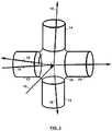
- the position of the crossover (intersection of incident and detected light beams) within the trapped dropletcan be set via separate optics: i.e. independently of the position of the optical surfaces, e.g. in backscatter via NIBS technology (described in US Pat. No. 6,016,195 ) - see Fig. 3 for example.
- the samplemay also be trapped between more than two surfaces e.g. see Fig. 2 (12, 14, 22, 24), and opposing surfaces may be non-parallel - Fig. 1(d) .
- the surfaces exposed to the samplemay be any shape deemed convenient and/or necessary for efficient trapping of the sample via surface tension and/or optical deviation and focusing of the incident and detected beams.
- Fig. 1(b)the light enters the droplet 10 through one of the optical surfaces at some appropriate, well-defined angle and is detected in either forward 18F or backscatter 18B (again at some appropriate angle) through the optical surfaces or at a higher angle (typically, but not exclusively, 90 degrees to the input beam 18S) through the droplet side.
- the beamenters through the side of the droplet and is detected through either or both of upper and lower optical surfaces or through the droplet side.
- all optical beams (incident and detected)should have a well defined angle with respect to each other and should be pseudo-monochromatic, with centre wavelength, ⁇ .
- the ISO standard for DLS(ISO 22412) states that the reported size should be +/-2% of the validated value of a standard sample.
- ⁇is the angle between the incident and detected beams.
- nis the refractive index of the dispersant in which the particles are dispersed.
- k Bis the Boltzmann constant and T is the temperature.
- ⁇ to ⁇ 2% for DLSThe requirements of SLS are a subset of ⁇ +/- 1.5% and ⁇ +/- 2%.
- Fig. 3One embodiment of the scheme is shown in Fig. 3 .
- the entire apparatus 30can fit inside the cuvette holder of a Zetasizer Nano particle characterization instrument underneath the thermal cap in order to provide degree of thermal control appropriate to S/DLS.
- the Zetasizer Nano particle characterization instrumentis available from Malvern Instruments of Malvern, UK, and is discussed in more detail in US application nos. 61/206,688 and 61/195,647 .
- the samplecan be re-pipetted for further use and any material left on the optical surfaces removed with easy access.
- Another approach not forming part of the present inventioninvolves a semi disposable sample presentation scheme for the measurement of dynamic and static light scattering for size and molecular weight determination in forward, side and backscatter.
- This schemecan allow for presentation of very small sample volumes to D/SLS instruments in an easy to use and semi-disposable format.
- a length of capillary 40is held in place (as required by the optical geometry of the instrument) and the tube filled from either end by attached tube or a pipette.
- the sampleis retained by one of three mechanisms. In the first instance, the capillary is small enough to trap the sample by surface tension with the other end of the capillary left open to atmosphere - Fig. 5(a) - for example. In the second instance, the top of the capillary is sealed by some means - Fig. 5(b) and Fig.
- the capillaryforms part of a flow circuit - Fig. 5(d) for example.
- the incident light beammay enter the sample through any side face of the capillary - Fig. 6 .
- One or more detection beamsmay also exit the cell through any or all of the side faces of the capillary.
- the capillary 40is held in place by a carrier 42 - Fig. 7 , which is then located into the instrument.
- the dimensions of the carriermatch those of a standard cuvette, such that it enables use in an instrument in which standard cuvettes are used. Typical dimensions of such a carrier are shown in Fig. 8 .
- a device for cutting the capillary to length whilst fitting into the carrieris also proposed, an example of which is shown in Fig. 7(b) .
- the sampleis pippetted into the bottom of the capillary as shown in Fig. 5 - the large hole in the base of the carrier - Fig. 7 - is included for this purpose. Once the measurement is complete the sample may then be repippetted out of the capillary for further analysis.
- capillarybecomes dirty in use it may be cheaply disposed of and a new one fitted for further measurements.
- Capillaries of 0.5mm internal dimensions and smallerare readily available thereby allowing convenient, semi-disposable measurement volumes of 10's to 100's of nanolitres for the first time.
- a piston 50 or other pumping mechanismmay be provided to draw a precise amount of a liquid sample into a capillary tube, hold it (if necessary), and then expel it (if necessary).
- the use of a pistoncan allow even a very small drop to be positioned precisely within a capillary tube in the path of an incident beam.
- the pistonmay be advanced by a screw, a motor, or another suitable mechanism.
Landscapes
- Chemical & Material Sciences (AREA)
- General Health & Medical Sciences (AREA)
- Life Sciences & Earth Sciences (AREA)
- Health & Medical Sciences (AREA)
- Analytical Chemistry (AREA)
- Biochemistry (AREA)
- Physics & Mathematics (AREA)
- General Physics & Mathematics (AREA)
- Immunology (AREA)
- Pathology (AREA)
- Dispersion Chemistry (AREA)
- Optical Measuring Cells (AREA)
- Investigating Or Analysing Materials By Optical Means (AREA)
Description
- This invention relates to methods and apparatus for detecting characteristics of particles suspended in a liquid sample droplet through the use of Dynamic Light Scattering (DLS) measurements.
- SLS and DLS measurements are typically performed using cuvettes with high-quality optical surfaces, which can be glass, in order to reduce scattering from static surfaces. These can be relatively expensive, and they can use a relatively large amount of sample material. It is also difficult to clean off residue from some types of samples, such as proteins.
US 2007/0224087 discloses an apparatus and method for airborne chemical and biological sample collection and detection, in which a gas-liquid interface is formed in a gap of a detection chamber and analysis of contaminants is carried out on light reflected or scattered from the meniscus of a drop to an optical sensor within the detection chamber.US 2006/0110818 discloses an aerosol-into-liquid collector for collecting gas-borne particles from a large volume of gas into a small volume of liquid, in which a linear quadrupole concentrates particles flowing in a gas to combine with a small volume of collection liquid used as an input to an instrument for identifying analytes in the particles.- This means that these both documents disclose a method of measuring characteristics of particles in a liquid sample droplet, comprising:supporting the liquid sample droplet by surface tension;illuminating the supported liquid sample droplet along an illumination axis with a spatially coherent light beam so as to cause the coherent light to be scattered across a scattering zone;detecting at least a portion of the scattered light along a first predetermined scattering detection axis after it is scattered by the particles in the supported liquid sample droplet, wherein the illumination axis and the detection axis are oriented at an angle with respect to each other that allows light scattered at that angle across the scattering zone to be detected.
US 2008/285032 discloses a dynamic light scattering experiment.- According to the invention there is provided a method of and apparatus for measuring the size of particles suspended in a liquid sample droplet, as defined by the appended claims.
Fig. 1 is a series of diagrams illustrating the use of optical components to trap sample droplets in various static and dynamic light scattering measurement configurations with one or two-face optical layouts;Fig. 2 is diagram illustrating the use of optical components to trap a sample droplet in a dynamic light scattering measurement configuration with a multiple-face optical layout;Fig. 3A is an isometric projection of a holder for use with light scattering measurement configurations such as those shown inFig. 1 ;Fig. 3B is a cross-sectional view of the holder ofFig. 3A that uses NIBS to position crossover of an incident beam;Fig. 3C is a cutaway view of the holder ofFig. 3A ;Fig. 4 is a three-view drawing of the holder showing illustrative overall dimensions to fit in commonly found cuvette holders;Fig. 5A is a diagram showing a sample trapped by surface tension within a capillary;Fig. 5B is a diagram of a sample trapped by atmospheric pressure via a pinched top;Fig. 5C is a diagram of a sample trapped by atmospheric pressure via a sealed top;Fig. 5D is a diagram of a sample trapped within a capillary as part of a flow path;Fig. 6 is a cross-sectional diagram showing an optical geometry for a capillary tube;Fig. 7A is an illustrative implementation of a capillary carrier including a slot at the top to trap and seal a flexible tube (attached to the top end of the capillary) for atmospheric trapping of sample as show inFig. 5B ;Fig. 7B is an illustrative implementation of a capillary carrier including a capillary cutter 44; andFig. 8 is three-view drawing of the capillary carrier ofFig. 7A holder showing illustrative overall dimensions to fit in commonly found cuvette holders.- Referring to
Fig. 1 , an illustrative embodiment of a particle characteristics measuring instrument can perform trapped droplet sample presentation for dynamic light scattering instruments in forward, side and backscatter. Static light scattering instruments are examples not forming part of the present invention. - S/DLS measurements can require very small sample volumes to reduce costs. Further, S/DLS measurements require very high optical quality surfaces in order to reduce scattering from static surfaces, precluding the use of low optical quality disposable plastic cells. Further still, proteins, for example, are often very difficult to clean from glass cuvettes that are typically quite deep and prevent the entry of mechanical cleaning devices, such as brushes.
- In instruments according to the invention, however, a
sample droplet 10 is placed on a loweroptical surface 12 -- seeFig. 1(a) . In one embodiment, theincident light beam 16 and detectedlight beam 18 intersect within the droplet, with the droplet in contact only with the lower surface. In another embodiment the upperoptical surface 14 is moved down until it makes contact with the sample -Fig. 1 (b,c,d). The sample droplet wicks onto the upper surface, whilst remaining attached to the lower surface. The sample is trapped by surface tension. The upper surface is then drawn up to create a sample bridge within which the incident and detection beams can intersect. The distance between the optical surfaces would typically be of the order of 1-2mm. The position of the crossover (intersection of incident and detected light beams) within the trapped droplet can be set via separate optics: i.e. independently of the position of the optical surfaces, e.g. in backscatter via NIBS technology (described inUS Pat. No. 6,016,195 ) - seeFig. 3 for example. The sample may also be trapped between more than two surfaces e.g. seeFig. 2 (12, 14, 22, 24), and opposing surfaces may be non-parallel -Fig. 1(d) . The surfaces exposed to the sample may be any shape deemed convenient and/or necessary for efficient trapping of the sample via surface tension and/or optical deviation and focusing of the incident and detected beams. - In
Fig. 1(b) , the light enters thedroplet 10 through one of the optical surfaces at some appropriate, well-defined angle and is detected in either forward 18F orbackscatter 18B (again at some appropriate angle) through the optical surfaces or at a higher angle (typically, but not exclusively, 90 degrees to theinput beam 18S) through the droplet side. InFig. 1(c) the beam enters through the side of the droplet and is detected through either or both of upper and lower optical surfaces or through the droplet side. In all proposed cases,Fig. 1(a)-(d) , all optical beams (incident and detected) should have a well defined angle with respect to each other and should be pseudo-monochromatic, with centre wavelength, λ. The ISO standard for DLS (ISO 22412) states that the reported size should be +/-2% of the validated value of a standard sample. The Cumulants analysis is the standard basic reduction and it equates the measured quantity, g1, the correlation function, to the fit,


- In which θ is the angle between the incident and detected beams. n, is the refractive index of the dispersant in which the particles are dispersed. The particle radius, r, is then related to the diffusion coefficient via the Stokes-Einstein relation

- Where, kB is the Boltzmann constant and T is the temperature. Via Eq.(2), q2 should be defined to < 2% to meet the ISO standard and thence θ to within

- One embodiment of the scheme is shown in
Fig. 3 . Theentire apparatus 30 can fit inside the cuvette holder of a Zetasizer Nano particle characterization instrument underneath the thermal cap in order to provide degree of thermal control appropriate to S/DLS. The Zetasizer Nano particle characterization instrument is available from Malvern Instruments of Malvern, UK, and is discussed in more detail inUS application nos. 61/206,688 61/195,647 - Once measured the sample can be re-pipetted for further use and any material left on the optical surfaces removed with easy access.
- Another approach not forming part of the present invention involves a semi disposable sample presentation scheme for the measurement of dynamic and static light scattering for size and molecular weight determination in forward, side and backscatter. This scheme can allow for presentation of very small sample volumes to D/SLS instruments in an easy to use and semi-disposable format.
- Good optical quality glass or plastic capillary tubing is available relatively cheaply now and the following scheme is proposed -
Fig. 5 . A length ofcapillary 40 is held in place (as required by the optical geometry of the instrument) and the tube filled from either end by attached tube or a pipette. The sample is retained by one of three mechanisms. In the first instance, the capillary is small enough to trap the sample by surface tension with the other end of the capillary left open to atmosphere -Fig. 5(a) - for example. In the second instance, the top of the capillary is sealed by some means -Fig. 5(b) and Fig. 5(c) for example - so that the sample is trapped within the capillary by atmospheric pressure at the capillary bottom (sample end inFig. 5 ). In the third instance, the capillary forms part of a flow circuit -Fig. 5(d) for example. - The incident light beam may enter the sample through any side face of the capillary -
Fig. 6 . One or more detection beams may also exit the cell through any or all of the side faces of the capillary. - The capillary 40 is held in place by a carrier 42 -
Fig. 7 , which is then located into the instrument. The dimensions of the carrier match those of a standard cuvette, such that it enables use in an instrument in which standard cuvettes are used. Typical dimensions of such a carrier are shown inFig. 8 . A device for cutting the capillary to length whilst fitting into the carrier is also proposed, an example of which is shown inFig. 7(b) . Once in place the sample is pippetted into the bottom of the capillary as shown inFig. 5 - the large hole in the base of the carrier -Fig. 7 - is included for this purpose. Once the measurement is complete the sample may then be repippetted out of the capillary for further analysis. - If the capillary becomes dirty in use it may be cheaply disposed of and a new one fitted for further measurements. Capillaries of 0.5mm internal dimensions and smaller are readily available thereby allowing convenient, semi-disposable measurement volumes of 10's to 100's of nanolitres for the first time.
- Referring to
Fig. 9 , apiston 50 or other pumping mechanism may be provided to draw a precise amount of a liquid sample into a capillary tube, hold it (if necessary), and then expel it (if necessary). The use of a piston can allow even a very small drop to be positioned precisely within a capillary tube in the path of an incident beam. The piston may be advanced by a screw, a motor, or another suitable mechanism.


Claims (16)
- A method of measuring characteristics of particles suspended in a liquid sample droplet (10), comprising:supporting the liquid sample droplet (10) by surface tension;illuminating the supported liquid sample droplet (10) along an illumination axis (16) with a spatially coherent light beam so as to cause the coherent light to be scattered across a scattering zone;detecting at least a portion of the scattered light along a first predetermined scattering detection axis (18) after it is scattered by the particles in the supported liquid sample droplet (10), wherein the illumination axis (16) and the detection axis (18) are oriented at an angle with respect to each other that allows light scattered at that angle across the scattering zone to be detected; andderiving a dynamic light scattering measurement for a predetermined angular resolution from results of the step of detecting to derive the characteristics of the particles suspended in the liquid sample droplet (10).
- The method of claim 1 wherein the liquid sample droplet (10) is supported in a gap defined by two wicking surfaces.
- The method of claim 1 wherein the step of detecting or illuminating is performed through a supporting surface of the liquid sample droplet.
- The method of any preceding claim including further steps of detecting along further detection axes (18B, 18F, 18S) that are oriented at further angles with respect to the illumination axis (16).
- The method of claim 1 wherein the step of supporting includes supporting the liquid sample droplet (10) on a sample carrier, and wherein the method further includes the step of positioning the sample carrier for performing a measurement by placing the sample carrier inside a holder with dimensions to fit in cuvette holders for holding a cuvette; wherein the step of detecting detects backscattered light.
- The method of claim 5, wherein the sample carrier comprises a reflector, and illuminating the supported liquid sample droplet comprises using the reflector to direct a horizontal incident light beam to illuminate the supported liquid sample droplet in a vertical direction.
- The method of claim 6, wherein the sample carrier comprises an aperture, and illuminating the supported liquid sample droplet comprises illuminating the reflector through the aperture.
- The method of any of claims 1 to 4 wherein the step of detecting detects: i) backscattered light; and/or ii) time-averaged or time-dependent scattered light for a sample.
- An instrument for measuring characteristics of particles suspended in a liquid sample droplet (10), comprising:one or more wicking surfaces for receiving and supporting a liquid sample droplet;a spatially coherent light source having an illumination axis (16) directed proximate the one or more wicking surfaces so as to cause coherent light from the source to be scattered across a scattering zone;at least one spatially coherent scattered light detector positioned to receive light scattered by the particles in the liquid sample along a first predetermined scattering detection axis (18) that is oriented at an angle with respect to the illumination axis of the light source when the liquid sample (10) is trapped by the one or more wicking surfaces, wherein the angle between the predetermined scattering detection axis and the illumination axis (16) allows the detector to detect coherent light scattered at that angle across the scattering zone,wherein the instrument is configured to derive a dynamic light scattering measurement for a predetermined angular resolution from the detected light to derive the characteristics of the particles suspended in the liquid sample droplet (10).
- The instrument of claim 9 wherein the one or more wicking surfaces are each part of one or more transparent optical parts, the spatially coherent light source being positioned to direct light through a first wicking surface of the one or more wicking surfaces and the light detector being positioned to receive scattered light through the first wicking surface.
- The instrument of claims 9 or 10 wherein the detector is positioned to receive backscattered light from the sample.
- The instrument of claim 11 further including a supporting body positioned to hold the one or more wicking surface in place, the supporting body being part of a removable sample carrier (30) that can be removed from the instrument.
- The instrument of claim 12, wherein the instrument further comprises a holder for holding a cuvette, and the sample carrier is configured to fit inside the holder, the holder having dimensions to fit in cuvette holders for holding a cuvette.
- The instrument of claim 12 or 13, wherein the sample carrier comprises a reflector operable to direct a horizontal incident light beam (16) in a vertical direction to illuminate the sample droplet on one of the one or more wicking surfaces, the supporting body (30) holding the reflector in place.
- The instrument of claim 14, wherein the sample carrier comprises an aperture for the horizontal incident light beam (16) to pass through in order to the reach the reflector.
- The instrument of any of claims 9 to 11 wherein a gap defined by a first and second of the one or more wicking surfaces is sized to hold an aqueous sample between the first wicking surface and the second wicking surface by surface tension.
Applications Claiming Priority (2)
| Application Number | Priority Date | Filing Date | Title |
|---|---|---|---|
| US20913909P | 2009-03-04 | 2009-03-04 | |
| PCT/GB2010/050383WO2010100502A1 (en) | 2009-03-04 | 2010-03-04 | Particle characterization |
Publications (2)
| Publication Number | Publication Date |
|---|---|
| EP2404154A1 EP2404154A1 (en) | 2012-01-11 |
| EP2404154B1true EP2404154B1 (en) | 2020-11-11 |
Family
ID=42174646
Family Applications (1)
| Application Number | Title | Priority Date | Filing Date |
|---|---|---|---|
| EP10707345.4AActiveEP2404154B1 (en) | 2009-03-04 | 2010-03-04 | Particle characterization |
Country Status (4)
| Country | Link |
|---|---|
| EP (1) | EP2404154B1 (en) |
| JP (2) | JP2012519839A (en) |
| CN (1) | CN102341690B (en) |
| WO (1) | WO2010100502A1 (en) |
Families Citing this family (7)
| Publication number | Priority date | Publication date | Assignee | Title |
|---|---|---|---|---|
| GB2480596A (en)* | 2010-01-29 | 2011-11-30 | Kenneth John Cunningham | Disposable light scattering cuvette for liquid sample held by surface tension |
| WO2012045846A1 (en)* | 2010-10-08 | 2012-04-12 | Hecus X-Ray Systems Gmbh | Apparatus and method for supporting a liquid sample for measuring scattering of electromagnetic radiation |
| JP6592765B2 (en)* | 2015-04-30 | 2019-10-23 | トライボテックス株式会社 | Particle counter |
| CA2995732A1 (en) | 2015-09-16 | 2017-03-23 | Thermo Electron Scientific Instruments Llc | Image analysis system and method |
| CN108431582A (en)* | 2015-12-28 | 2018-08-21 | Kbf企划株式会社 | Method and device for measuring gel particles |
| EP3309536A1 (en) | 2016-10-11 | 2018-04-18 | Malvern Panalytical Limited | Particle characterisation instrument |
| GB2572707A (en)* | 2016-12-14 | 2019-10-09 | Horiba Ltd | Particle physical-property measurement device |
Citations (3)
| Publication number | Priority date | Publication date | Assignee | Title |
|---|---|---|---|---|
| US20060110818A1 (en)* | 2004-11-19 | 2006-05-25 | Government Of The United States, As Represented By The Secretary, United States Army | Aerosol into liquid collector for depositing particles from a large volume of gas into a small volume of liquid |
| JP2008116314A (en)* | 2006-11-02 | 2008-05-22 | Seikoh Giken Co Ltd | Device for measuring trace quantity liquid |
| US20080285032A1 (en)* | 2006-08-04 | 2008-11-20 | Shimadzu Corporation | Light scattering detector |
Family Cites Families (17)
| Publication number | Priority date | Publication date | Assignee | Title |
|---|---|---|---|---|
| JPS5973753A (en)* | 1982-10-21 | 1984-04-26 | Toshiba Corp | Ultra-trace spectrophotometer |
| DE3344387A1 (en)* | 1983-12-08 | 1985-06-20 | Hoechst Ag, 6230 Frankfurt | PHOTOMETER HEAD FOR SMALL MEASURING VOLUME |
| JPH0448245A (en)* | 1990-06-15 | 1992-02-18 | Canon Inc | particle measuring device |
| JPH05340885A (en)* | 1992-06-08 | 1993-12-24 | Matsushita Electric Ind Co Ltd | Particle inspection method |
| JP2910596B2 (en)* | 1994-12-27 | 1999-06-23 | 株式会社島津製作所 | Particle size distribution analyzer |
| DE19725211C1 (en) | 1997-06-15 | 1998-06-04 | Alv Laser Vertriebsgesellschaf | Optical fibre detector for liquid suspension concentration measurement |
| KR19990011927A (en)* | 1997-07-25 | 1999-02-18 | 윤종용 | Optical particle concentration meter and measuring method thereof |
| JP3475097B2 (en)* | 1998-11-06 | 2003-12-08 | 株式会社堀場製作所 | Particle size distribution measuring device |
| EP1210579B1 (en)* | 1999-08-20 | 2008-06-04 | NanoDrop Technologies, LLC | Liquid photometer using surface tension to contain sample |
| JP4002173B2 (en)* | 2002-12-13 | 2007-10-31 | 株式会社栃木ニコン | Terahertz spectrometer |
| US20070224087A1 (en)* | 2004-07-08 | 2007-09-27 | Zhong Ding | Airborne material collection and detection method and apparatus |
| US7375815B2 (en)* | 2004-10-12 | 2008-05-20 | Agilent Technologies, Inc. | Optical devices, systems and method for producing a collimated light path |
| US20060109468A1 (en)* | 2004-11-24 | 2006-05-25 | Evans Richard W | Devices, methods, and systems for measuring an optical property of a sample |
| WO2006086459A2 (en)* | 2005-02-11 | 2006-08-17 | Nanodrop Technologies, Inc. | Fluorescence measurement method utilizing surface tension apparatus |
| JP2007170984A (en)* | 2005-12-22 | 2007-07-05 | Shimadzu Corp | Sample cell and spectrophotometer using the sample cell |
| US8681340B2 (en)* | 2006-05-12 | 2014-03-25 | Norman McMillan | Microvolume analysis system |
| EP2071317B1 (en)* | 2006-10-06 | 2020-05-20 | Shimadzu Corporation | Spectrophotometer |
- 2010
- 2010-03-04WOPCT/GB2010/050383patent/WO2010100502A1/enactiveApplication Filing
- 2010-03-04CNCN2010800107028Apatent/CN102341690B/enactiveActive
- 2010-03-04JPJP2011552527Apatent/JP2012519839A/ennot_activeCeased
- 2010-03-04EPEP10707345.4Apatent/EP2404154B1/enactiveActive
- 2014
- 2014-07-07JPJP2014139417Apatent/JP5945568B2/enactiveActive
Patent Citations (3)
| Publication number | Priority date | Publication date | Assignee | Title |
|---|---|---|---|---|
| US20060110818A1 (en)* | 2004-11-19 | 2006-05-25 | Government Of The United States, As Represented By The Secretary, United States Army | Aerosol into liquid collector for depositing particles from a large volume of gas into a small volume of liquid |
| US20080285032A1 (en)* | 2006-08-04 | 2008-11-20 | Shimadzu Corporation | Light scattering detector |
| JP2008116314A (en)* | 2006-11-02 | 2008-05-22 | Seikoh Giken Co Ltd | Device for measuring trace quantity liquid |
Non-Patent Citations (2)
| Title |
|---|
| ANONYMOUS: "Dynamic light scattering - Wikipedia", 28 November 2016 (2016-11-28), XP055340001, Retrieved from the Internet <URL:https://en.wikipedia.org/wiki/Dynamic_light_scattering> [retrieved on 20170127]* |
| ANONYMOUS: "Static light scattering - Wikipedia", 17 September 2016 (2016-09-17), XP055340000, Retrieved from the Internet <URL:https://en.wikipedia.org/wiki/Static_light_scattering> [retrieved on 20170127]* |
Also Published As
| Publication number | Publication date |
|---|---|
| CN102341690A (en) | 2012-02-01 |
| CN102341690B (en) | 2013-10-09 |
| JP2012519839A (en) | 2012-08-30 |
| EP2404154A1 (en) | 2012-01-11 |
| JP5945568B2 (en) | 2016-07-05 |
| WO2010100502A1 (en) | 2010-09-10 |
| JP2014186039A (en) | 2014-10-02 |
Similar Documents
| Publication | Publication Date | Title |
|---|---|---|
| EP2404154B1 (en) | Particle characterization | |
| US8675197B2 (en) | Particle characterization | |
| US8947662B1 (en) | Methods and apparatus for biomedical agent multi-dimension measuring and analysis | |
| JP5726064B2 (en) | Optical inspection method for cuvettes, inserts, adapters and small amounts of liquid | |
| CN113477149B (en) | Microfluidic devices and methods of making and using the same | |
| EP2948756B1 (en) | Optical measuring apparatus and method for the analysis of samples contained in liquid drops | |
| JP2014503195A5 (en) | ||
| EP3347694B1 (en) | Cuvette assembly for optical microscopy of nanoparticles in liquids | |
| US9347869B2 (en) | Multiwell plate lid for improved optical measurements | |
| US8634076B2 (en) | Multi-sample scattering measurements | |
| AU2013407022B2 (en) | Method and apparatus for online analysis by laser-induced spectroscopy | |
| WO1994022000A1 (en) | Measuring chamber for flow cytometer | |
| EP0409293A2 (en) | Optical coupling gel for flow cytometry apparatuses and the like | |
| US9417176B2 (en) | Method and apparatus for detecting and registering properties of samples | |
| RU2764676C1 (en) | Apparatus with a microfluid chip for measuring the optical strength and imaging cells using the microfluid chip configuration and dynamics | |
| US11131632B2 (en) | Measuring device with injector and spray deflector | |
| JP2012519839A5 (en) | ||
| JP6747455B2 (en) | Detection method, detection system, and detection device | |
| US9164047B2 (en) | Apparatus and method for supporting a liquid sample for measuring scattering of electromagnetic radiation | |
| EP2404157B1 (en) | Method for measuring particle size by dynamic or static light scattering measurement | |
| WO2015178124A1 (en) | Particle analysis device | |
| JP2001514755A (en) | Spectrophotometric cuvette | |
| JP2007003417A (en) | Optical measuring device | |
| Lodder et al. | A disposable liquid microcell for near-infrared reflectance analysis | |
| EP1950553B1 (en) | Liquid photometer using surface tension to contain sample |
Legal Events
| Date | Code | Title | Description |
|---|---|---|---|
| PUAI | Public reference made under article 153(3) epc to a published international application that has entered the european phase | Free format text:ORIGINAL CODE: 0009012 | |
| 17P | Request for examination filed | Effective date:20110915 | |
| AK | Designated contracting states | Kind code of ref document:A1 Designated state(s):AT BE BG CH CY CZ DE DK EE ES FI FR GB GR HR HU IE IS IT LI LT LU LV MC MK MT NL NO PL PT RO SE SI SK SM TR | |
| DAX | Request for extension of the european patent (deleted) | ||
| STAA | Information on the status of an ep patent application or granted ep patent | Free format text:STATUS: EXAMINATION IS IN PROGRESS | |
| 17Q | First examination report despatched | Effective date:20170206 | |
| RAP1 | Party data changed (applicant data changed or rights of an application transferred) | Owner name:MALVERN PANALYTICAL LIMITED | |
| GRAP | Despatch of communication of intention to grant a patent | Free format text:ORIGINAL CODE: EPIDOSNIGR1 | |
| STAA | Information on the status of an ep patent application or granted ep patent | Free format text:STATUS: GRANT OF PATENT IS INTENDED | |
| RIC1 | Information provided on ipc code assigned before grant | Ipc:G01N 21/47 20060101ALI20200630BHEP Ipc:G01N 15/02 20060101AFI20200630BHEP Ipc:G01N 21/51 20060101ALI20200630BHEP Ipc:G01N 21/03 20060101ALI20200630BHEP | |
| INTG | Intention to grant announced | Effective date:20200729 | |
| GRAS | Grant fee paid | Free format text:ORIGINAL CODE: EPIDOSNIGR3 | |
| GRAA | (expected) grant | Free format text:ORIGINAL CODE: 0009210 | |
| STAA | Information on the status of an ep patent application or granted ep patent | Free format text:STATUS: THE PATENT HAS BEEN GRANTED | |
| AK | Designated contracting states | Kind code of ref document:B1 Designated state(s):AT BE BG CH CY CZ DE DK EE ES FI FR GB GR HR HU IE IS IT LI LT LU LV MC MK MT NL NO PL PT RO SE SI SK SM TR | |
| REG | Reference to a national code | Ref country code:GB Ref legal event code:FG4D | |
| REG | Reference to a national code | Ref country code:CH Ref legal event code:EP | |
| REG | Reference to a national code | Ref country code:AT Ref legal event code:REF Ref document number:1333954 Country of ref document:AT Kind code of ref document:T Effective date:20201115 | |
| REG | Reference to a national code | Ref country code:DE Ref legal event code:R096 Ref document number:602010065882 Country of ref document:DE | |
| REG | Reference to a national code | Ref country code:IE Ref legal event code:FG4D | |
| REG | Reference to a national code | Ref country code:NL Ref legal event code:MP Effective date:20201111 | |
| REG | Reference to a national code | Ref country code:AT Ref legal event code:MK05 Ref document number:1333954 Country of ref document:AT Kind code of ref document:T Effective date:20201111 | |
| PG25 | Lapsed in a contracting state [announced via postgrant information from national office to epo] | Ref country code:GR Free format text:LAPSE BECAUSE OF FAILURE TO SUBMIT A TRANSLATION OF THE DESCRIPTION OR TO PAY THE FEE WITHIN THE PRESCRIBED TIME-LIMIT Effective date:20210212 Ref country code:FI Free format text:LAPSE BECAUSE OF FAILURE TO SUBMIT A TRANSLATION OF THE DESCRIPTION OR TO PAY THE FEE WITHIN THE PRESCRIBED TIME-LIMIT Effective date:20201111 Ref country code:NO Free format text:LAPSE BECAUSE OF FAILURE TO SUBMIT A TRANSLATION OF THE DESCRIPTION OR TO PAY THE FEE WITHIN THE PRESCRIBED TIME-LIMIT Effective date:20210211 Ref country code:PT Free format text:LAPSE BECAUSE OF FAILURE TO SUBMIT A TRANSLATION OF THE DESCRIPTION OR TO PAY THE FEE WITHIN THE PRESCRIBED TIME-LIMIT Effective date:20210311 | |
| PG25 | Lapsed in a contracting state [announced via postgrant information from national office to epo] | Ref country code:PL Free format text:LAPSE BECAUSE OF FAILURE TO SUBMIT A TRANSLATION OF THE DESCRIPTION OR TO PAY THE FEE WITHIN THE PRESCRIBED TIME-LIMIT Effective date:20201111 Ref country code:SE Free format text:LAPSE BECAUSE OF FAILURE TO SUBMIT A TRANSLATION OF THE DESCRIPTION OR TO PAY THE FEE WITHIN THE PRESCRIBED TIME-LIMIT Effective date:20201111 Ref country code:LV Free format text:LAPSE BECAUSE OF FAILURE TO SUBMIT A TRANSLATION OF THE DESCRIPTION OR TO PAY THE FEE WITHIN THE PRESCRIBED TIME-LIMIT Effective date:20201111 Ref country code:IS Free format text:LAPSE BECAUSE OF FAILURE TO SUBMIT A TRANSLATION OF THE DESCRIPTION OR TO PAY THE FEE WITHIN THE PRESCRIBED TIME-LIMIT Effective date:20210311 Ref country code:AT Free format text:LAPSE BECAUSE OF FAILURE TO SUBMIT A TRANSLATION OF THE DESCRIPTION OR TO PAY THE FEE WITHIN THE PRESCRIBED TIME-LIMIT Effective date:20201111 Ref country code:BG Free format text:LAPSE BECAUSE OF FAILURE TO SUBMIT A TRANSLATION OF THE DESCRIPTION OR TO PAY THE FEE WITHIN THE PRESCRIBED TIME-LIMIT Effective date:20210211 | |
| REG | Reference to a national code | Ref country code:LT Ref legal event code:MG9D | |
| PG25 | Lapsed in a contracting state [announced via postgrant information from national office to epo] | Ref country code:HR Free format text:LAPSE BECAUSE OF FAILURE TO SUBMIT A TRANSLATION OF THE DESCRIPTION OR TO PAY THE FEE WITHIN THE PRESCRIBED TIME-LIMIT Effective date:20201111 | |
| PG25 | Lapsed in a contracting state [announced via postgrant information from national office to epo] | Ref country code:EE Free format text:LAPSE BECAUSE OF FAILURE TO SUBMIT A TRANSLATION OF THE DESCRIPTION OR TO PAY THE FEE WITHIN THE PRESCRIBED TIME-LIMIT Effective date:20201111 Ref country code:CZ Free format text:LAPSE BECAUSE OF FAILURE TO SUBMIT A TRANSLATION OF THE DESCRIPTION OR TO PAY THE FEE WITHIN THE PRESCRIBED TIME-LIMIT Effective date:20201111 Ref country code:SK Free format text:LAPSE BECAUSE OF FAILURE TO SUBMIT A TRANSLATION OF THE DESCRIPTION OR TO PAY THE FEE WITHIN THE PRESCRIBED TIME-LIMIT Effective date:20201111 Ref country code:RO Free format text:LAPSE BECAUSE OF FAILURE TO SUBMIT A TRANSLATION OF THE DESCRIPTION OR TO PAY THE FEE WITHIN THE PRESCRIBED TIME-LIMIT Effective date:20201111 Ref country code:SM Free format text:LAPSE BECAUSE OF FAILURE TO SUBMIT A TRANSLATION OF THE DESCRIPTION OR TO PAY THE FEE WITHIN THE PRESCRIBED TIME-LIMIT Effective date:20201111 Ref country code:LT Free format text:LAPSE BECAUSE OF FAILURE TO SUBMIT A TRANSLATION OF THE DESCRIPTION OR TO PAY THE FEE WITHIN THE PRESCRIBED TIME-LIMIT Effective date:20201111 | |
| REG | Reference to a national code | Ref country code:DE Ref legal event code:R097 Ref document number:602010065882 Country of ref document:DE | |
| PG25 | Lapsed in a contracting state [announced via postgrant information from national office to epo] | Ref country code:DK Free format text:LAPSE BECAUSE OF FAILURE TO SUBMIT A TRANSLATION OF THE DESCRIPTION OR TO PAY THE FEE WITHIN THE PRESCRIBED TIME-LIMIT Effective date:20201111 | |
| PLBE | No opposition filed within time limit | Free format text:ORIGINAL CODE: 0009261 | |
| STAA | Information on the status of an ep patent application or granted ep patent | Free format text:STATUS: NO OPPOSITION FILED WITHIN TIME LIMIT | |
| 26N | No opposition filed | Effective date:20210812 | |
| PG25 | Lapsed in a contracting state [announced via postgrant information from national office to epo] | Ref country code:IT Free format text:LAPSE BECAUSE OF FAILURE TO SUBMIT A TRANSLATION OF THE DESCRIPTION OR TO PAY THE FEE WITHIN THE PRESCRIBED TIME-LIMIT Effective date:20201111 Ref country code:MC Free format text:LAPSE BECAUSE OF FAILURE TO SUBMIT A TRANSLATION OF THE DESCRIPTION OR TO PAY THE FEE WITHIN THE PRESCRIBED TIME-LIMIT Effective date:20201111 Ref country code:NL Free format text:LAPSE BECAUSE OF FAILURE TO SUBMIT A TRANSLATION OF THE DESCRIPTION OR TO PAY THE FEE WITHIN THE PRESCRIBED TIME-LIMIT Effective date:20201111 | |
| REG | Reference to a national code | Ref country code:CH Ref legal event code:PL | |
| PG25 | Lapsed in a contracting state [announced via postgrant information from national office to epo] | Ref country code:ES Free format text:LAPSE BECAUSE OF FAILURE TO SUBMIT A TRANSLATION OF THE DESCRIPTION OR TO PAY THE FEE WITHIN THE PRESCRIBED TIME-LIMIT Effective date:20201111 Ref country code:SI Free format text:LAPSE BECAUSE OF FAILURE TO SUBMIT A TRANSLATION OF THE DESCRIPTION OR TO PAY THE FEE WITHIN THE PRESCRIBED TIME-LIMIT Effective date:20201111 | |
| REG | Reference to a national code | Ref country code:BE Ref legal event code:MM Effective date:20210331 | |
| PG25 | Lapsed in a contracting state [announced via postgrant information from national office to epo] | Ref country code:LI Free format text:LAPSE BECAUSE OF NON-PAYMENT OF DUE FEES Effective date:20210331 Ref country code:LU Free format text:LAPSE BECAUSE OF NON-PAYMENT OF DUE FEES Effective date:20210304 Ref country code:CH Free format text:LAPSE BECAUSE OF NON-PAYMENT OF DUE FEES Effective date:20210331 Ref country code:IE Free format text:LAPSE BECAUSE OF NON-PAYMENT OF DUE FEES Effective date:20210304 | |
| PG25 | Lapsed in a contracting state [announced via postgrant information from national office to epo] | Ref country code:IS Free format text:LAPSE BECAUSE OF FAILURE TO SUBMIT A TRANSLATION OF THE DESCRIPTION OR TO PAY THE FEE WITHIN THE PRESCRIBED TIME-LIMIT Effective date:20210311 | |
| PG25 | Lapsed in a contracting state [announced via postgrant information from national office to epo] | Ref country code:BE Free format text:LAPSE BECAUSE OF NON-PAYMENT OF DUE FEES Effective date:20210331 | |
| PG25 | Lapsed in a contracting state [announced via postgrant information from national office to epo] | Ref country code:HU Free format text:LAPSE BECAUSE OF FAILURE TO SUBMIT A TRANSLATION OF THE DESCRIPTION OR TO PAY THE FEE WITHIN THE PRESCRIBED TIME-LIMIT; INVALID AB INITIO Effective date:20100304 Ref country code:CY Free format text:LAPSE BECAUSE OF FAILURE TO SUBMIT A TRANSLATION OF THE DESCRIPTION OR TO PAY THE FEE WITHIN THE PRESCRIBED TIME-LIMIT Effective date:20201111 | |
| P01 | Opt-out of the competence of the unified patent court (upc) registered | Effective date:20230727 | |
| PG25 | Lapsed in a contracting state [announced via postgrant information from national office to epo] | Ref country code:MK Free format text:LAPSE BECAUSE OF FAILURE TO SUBMIT A TRANSLATION OF THE DESCRIPTION OR TO PAY THE FEE WITHIN THE PRESCRIBED TIME-LIMIT Effective date:20201111 | |
| PG25 | Lapsed in a contracting state [announced via postgrant information from national office to epo] | Ref country code:TR Free format text:LAPSE BECAUSE OF FAILURE TO SUBMIT A TRANSLATION OF THE DESCRIPTION OR TO PAY THE FEE WITHIN THE PRESCRIBED TIME-LIMIT Effective date:20201111 | |
| PG25 | Lapsed in a contracting state [announced via postgrant information from national office to epo] | Ref country code:MT Free format text:LAPSE BECAUSE OF FAILURE TO SUBMIT A TRANSLATION OF THE DESCRIPTION OR TO PAY THE FEE WITHIN THE PRESCRIBED TIME-LIMIT Effective date:20201111 | |
| PGFP | Annual fee paid to national office [announced via postgrant information from national office to epo] | Ref country code:DE Payment date:20250218 Year of fee payment:16 | |
| PGFP | Annual fee paid to national office [announced via postgrant information from national office to epo] | Ref country code:FR Payment date:20250218 Year of fee payment:16 | |
| PGFP | Annual fee paid to national office [announced via postgrant information from national office to epo] | Ref country code:GB Payment date:20250221 Year of fee payment:16 |